US9316390B2 - Lighting system for drilling rig - Google Patents
Lighting system for drilling rigDownload PDFInfo
- Publication number
- US9316390B2 US9316390B2US14/093,097US201314093097AUS9316390B2US 9316390 B2US9316390 B2US 9316390B2US 201314093097 AUS201314093097 AUS 201314093097AUS 9316390 B2US9316390 B2US 9316390B2
- Authority
- US
- United States
- Prior art keywords
- light
- frame
- support posts
- lighting system
- crown
- Prior art date
- Legal status (The legal status is an assumption and is not a legal conclusion. Google has not performed a legal analysis and makes no representation as to the accuracy of the status listed.)
- Active - Reinstated, expires
Links
- 238000005553drillingMethods0.000titleclaimsabstractdescription48
- 239000012530fluidSubstances0.000description9
- 238000009844basic oxygen steelmakingMethods0.000description3
- 238000005520cutting processMethods0.000description2
- VNWKTOKETHGBQD-UHFFFAOYSA-NmethaneChemical compoundCVNWKTOKETHGBQD-UHFFFAOYSA-N0.000description2
- 239000007787solidSubstances0.000description2
- 229910000831SteelInorganic materials0.000description1
- 230000007812deficiencyEffects0.000description1
- 239000007789gasSubstances0.000description1
- 229910052500inorganic mineralInorganic materials0.000description1
- 238000007689inspectionMethods0.000description1
- 230000007774longtermEffects0.000description1
- 239000002184metalSubstances0.000description1
- 239000011707mineralSubstances0.000description1
- 239000003345natural gasSubstances0.000description1
- 239000011435rockSubstances0.000description1
- 238000005070samplingMethods0.000description1
- 239000010959steelSubstances0.000description1
- 230000009897systematic effectEffects0.000description1
Images


Classifications
- F—MECHANICAL ENGINEERING; LIGHTING; HEATING; WEAPONS; BLASTING
- F21—LIGHTING
- F21V—FUNCTIONAL FEATURES OR DETAILS OF LIGHTING DEVICES OR SYSTEMS THEREOF; STRUCTURAL COMBINATIONS OF LIGHTING DEVICES WITH OTHER ARTICLES, NOT OTHERWISE PROVIDED FOR
- F21V21/00—Supporting, suspending, or attaching arrangements for lighting devices; Hand grips
- F21V21/02—Wall, ceiling, or floor bases; Fixing pendants or arms to the bases
- F21V21/025—Elongated bases having a U-shaped cross section
- F—MECHANICAL ENGINEERING; LIGHTING; HEATING; WEAPONS; BLASTING
- F21—LIGHTING
- F21V—FUNCTIONAL FEATURES OR DETAILS OF LIGHTING DEVICES OR SYSTEMS THEREOF; STRUCTURAL COMBINATIONS OF LIGHTING DEVICES WITH OTHER ARTICLES, NOT OTHERWISE PROVIDED FOR
- F21V33/00—Structural combinations of lighting devices with other articles, not otherwise provided for
- F—MECHANICAL ENGINEERING; LIGHTING; HEATING; WEAPONS; BLASTING
- F21—LIGHTING
- F21S—NON-PORTABLE LIGHTING DEVICES; SYSTEMS THEREOF; VEHICLE LIGHTING DEVICES SPECIALLY ADAPTED FOR VEHICLE EXTERIORS
- F21S8/00—Lighting devices intended for fixed installation
- F21S8/08—Lighting devices intended for fixed installation with a standard
- F21S8/085—Lighting devices intended for fixed installation with a standard of high-built type, e.g. street light
- F21S8/088—Lighting devices intended for fixed installation with a standard of high-built type, e.g. street light with lighting device mounted on top of the standard, e.g. for pedestrian zones
- E—FIXED CONSTRUCTIONS
- E21—EARTH OR ROCK DRILLING; MINING
- E21B—EARTH OR ROCK DRILLING; OBTAINING OIL, GAS, WATER, SOLUBLE OR MELTABLE MATERIALS OR A SLURRY OF MINERALS FROM WELLS
- E21B15/00—Supports for the drilling machine, e.g. derricks or masts
- F—MECHANICAL ENGINEERING; LIGHTING; HEATING; WEAPONS; BLASTING
- F21—LIGHTING
- F21V—FUNCTIONAL FEATURES OR DETAILS OF LIGHTING DEVICES OR SYSTEMS THEREOF; STRUCTURAL COMBINATIONS OF LIGHTING DEVICES WITH OTHER ARTICLES, NOT OTHERWISE PROVIDED FOR
- F21V21/00—Supporting, suspending, or attaching arrangements for lighting devices; Hand grips
- F21V21/10—Pendants, arms, or standards; Fixing lighting devices to pendants, arms, or standards
- F21V21/116—Fixing lighting devices to arms or standards
- F—MECHANICAL ENGINEERING; LIGHTING; HEATING; WEAPONS; BLASTING
- F21—LIGHTING
- F21V—FUNCTIONAL FEATURES OR DETAILS OF LIGHTING DEVICES OR SYSTEMS THEREOF; STRUCTURAL COMBINATIONS OF LIGHTING DEVICES WITH OTHER ARTICLES, NOT OTHERWISE PROVIDED FOR
- F21V21/00—Supporting, suspending, or attaching arrangements for lighting devices; Hand grips
- F21V21/14—Adjustable mountings
- F21V21/22—Adjustable mountings telescopic
- F—MECHANICAL ENGINEERING; LIGHTING; HEATING; WEAPONS; BLASTING
- F21—LIGHTING
- F21S—NON-PORTABLE LIGHTING DEVICES; SYSTEMS THEREOF; VEHICLE LIGHTING DEVICES SPECIALLY ADAPTED FOR VEHICLE EXTERIORS
- F21S8/00—Lighting devices intended for fixed installation
- F21S8/08—Lighting devices intended for fixed installation with a standard
- F21S8/085—Lighting devices intended for fixed installation with a standard of high-built type, e.g. street light
- F—MECHANICAL ENGINEERING; LIGHTING; HEATING; WEAPONS; BLASTING
- F21—LIGHTING
- F21W—INDEXING SCHEME ASSOCIATED WITH SUBCLASSES F21K, F21L, F21S and F21V, RELATING TO USES OR APPLICATIONS OF LIGHTING DEVICES OR SYSTEMS
- F21W2131/00—Use or application of lighting devices or systems not provided for in codes F21W2102/00-F21W2121/00
- F21W2131/10—Outdoor lighting
- F21W2131/1005—Outdoor lighting of working places, building sites or the like
- F—MECHANICAL ENGINEERING; LIGHTING; HEATING; WEAPONS; BLASTING
- F21—LIGHTING
- F21W—INDEXING SCHEME ASSOCIATED WITH SUBCLASSES F21K, F21L, F21S and F21V, RELATING TO USES OR APPLICATIONS OF LIGHTING DEVICES OR SYSTEMS
- F21W2131/00—Use or application of lighting devices or systems not provided for in codes F21W2102/00-F21W2121/00
- F21W2131/40—Lighting for industrial, commercial, recreational or military use
- F21W2131/402—Lighting for industrial, commercial, recreational or military use for working places
- F—MECHANICAL ENGINEERING; LIGHTING; HEATING; WEAPONS; BLASTING
- F21—LIGHTING
- F21W—INDEXING SCHEME ASSOCIATED WITH SUBCLASSES F21K, F21L, F21S and F21V, RELATING TO USES OR APPLICATIONS OF LIGHTING DEVICES OR SYSTEMS
- F21W2131/00—Use or application of lighting devices or systems not provided for in codes F21W2102/00-F21W2121/00
- F21W2131/40—Lighting for industrial, commercial, recreational or military use
- F21W2131/403—Lighting for industrial, commercial, recreational or military use for machines
Definitions
- the present inventionrelates generally to the field of drilling apparatuses, such as oil drilling rig arrangements, and in particular to a lighting system for use in an oil drilling rig.
- Drilling rigsare used to form wellbores for the purpose of extracting oil, natural gas or other fluids from subsurface deposits. Drilling rigs can also be used for sampling subsurface mineral deposits, testing rock or ground fluid properties and for installing subsurface utilities, instrumentations, tunnels or wells.
- drilling rigsmay be mobile equipment transportable by truck, rail, trailers, or similar, rigs may also be semi-permanent and permanent fixtures as in the case for oil drilling of large wells. Marine-based structures are also widely known. Generally, the term drilling rig refers to an arrangement of equipment that is used to penetrate the subsurface of the earth's crust.
- a conventional drilling rig 30is illustrated in FIG. 7 , where the drilling rig 30 includes a derrick 14 , which provides a support structure for a majority of the equipment used to raise and lower drillstring 25 into and out of a wellbore.
- the drillstring 25may be an assembled collection of drillpipe, drill collars, or any other assembled collection of assorted tools and equipment connected together and run into the wellbore to facilitate the drilling of a well.
- the drillstring 25may be raised and lowered into an dout of the wellbore by the draw-works 7 , which includes a spool powered by a motor or other power source 5 .
- a drill line 12which may be a thick, stranded metal cable, is run through a travelling block 11 .
- the crown block 13remains stationary while travelling block 11 moves vertically with the drillstring 25 .
- the combination of the crown block 13 and the travelling block 11provides a significant mechanical advantage for lifting the drillstring 25 .
- a swivel 18may be attached to the travelling block 11 to allow rotation of the drillstring 25 without twisting the travelling block 11
- the drilling rig 30further includes a rotary table 20 mounted in a rig floor 21 , which is used to rotate the drillstring 25 along with a kelly drive 19 .
- Kelly drive 19attached at an upper end to the swivel 18 and at a lower end to the drillstring 25 , is inserted through the rotary table 20 to rotate the drillstring 25 (drillstring rotation shown by arrow “R”).
- Kelly drive 19may be square, hexagonal, or any other polygonal-shaped tubing and is able to move freely vertically while the rotary table 20 rotates it.
- drilling rig 30may include a top drive (not shown) in place of kelly drive 19 and rotary table 20 .
- blowout preventersmay be located below the rig floor 21 and installed atop a wellhead 27 to prevent fluids and gases from escaping from the wellbore.
- An annular BOP 23 and one or more ram BOPs 24are shown and are commonly understood in the art.
- drilling fluidmay be circulated through the system to carry cuttings away from the bottom of the wellbore as drilling progresses.
- Drilling fluidmay be stored in mud tanks 1 before being drawn through suction line 3 by mud pumps 4 .
- Drilling fluid(drilling fluid route is indicated by arrows “F”) is then pumped from mud pumps 4 through a hose 6 , up a stand pipe 8 , through a flexible hose 9 , and down into the wellbore.
- Drilling fluid returning from the wellboreis routed through a flow line 28 to shakers 2 , which are used to separate drill cuttings from the drilling fluid before it is pumped back down the wellbore.
- Drilling operationstypically occur during daylight hours and visibility in and around the drilling rig has historically only been required when manual work is being done, inspection and calibration, for example. There is a desire to increase productivity by providing visibility during hours of low daylight, and this has thus far been accomplished by providing mobile lighting arrangements on vehicles proximate the drilling rig, or otherwise manually adding impromptu lighting arrangements.
- a lighting system for a drilling rigincluding a lighting frame attached to a crown of the drilling rig, wherein the lighting frame includes an adjustable frame portion attached to the crown of the drilling rig and a light bearing frame portion supported by the adjustable frame portion; at least one light support post attached to the light bearing frame portion for holding a lighting fixture; and,
- At least one lighting fixtureattached to each the light support post.
- the adjustable frame portionincludes at least four support posts for rigidly fixing the adjustable frame portion to the crown, and further includes, between at least two adjacent support posts, a first tubular load bearing member connected to one of the adjacent support posts; a second tubular load bearing member connected to the other of the adjacent support posts; an extendable frame member extending between and into each of the first and second tubular members; and means for fixing each of the first and second tubular members with respect to the extendable frame member; such that the first and second tubular load bearing members are moveable with respect to the extendable frame member to thereby adjust a distance between adjacent support posts.
- the means for fixingcomprises a pin extending through the respective tubular load bearing member and the extendable frame member.
- the at least two adjacent support postscomprises all of the at least four support posts; wherein the at least four support posts are arranged to form a generally rectangular shape.
- the light bearing frame portioncomprises an outer structural frame consisting of a plurality of connected beams forming a perimeter around which the at least one light fixture is attached.
- the light bearing frame portionfurther includes at least two cross-braces connecting a first side of the outer structural frame to a second side of the outer structural frame; the first and second sides being generally parallel to each other; at least one support brace connecting the at least two cross-braces to each other; and a locating brace connecting one of the at least one support brace to a third side of the outer structural frame; the third side being generally perpendicular to the first and second sizes.
- a second locating braceconnecting a second of the at least one support brace to a fourth size of the outer structural frame; the fourth side being generally perpendicular to the first and second sizes.
- At least one of the extendable frame memberscomprise a recess at a midpoint thereof sized and otherwise dimensioned to receive a main body portion of the locating brace, such that the recess restricts movement of the locating brace in a direction parallel to the extendable frame member.
- At the at least of the extendable frame memberscomprises two of the extendable frame members positioned parallel to each other.
- the light bearing portionfurther comprises a plurality of light holding platforms spaced around a perimeter of the outer structural frame; the light holding platforms each comprising a first portion for attaching to the outer structural frame and a second portion for holding the light support posts.
- each of the light support postsare adapted to hold at least two light fixtures.
- the at least two light fixturesare spaced vertically from each other.
- the corner support postsare rigidly affixed to the crown by a bracket positioned proximate a bottom end of each the corner support posts; the bracket being attachable to a body of the crown, proximate a base of the crown.
- a framefor holding at least one light fixture in a drilling rig arrangement; the frame including an adjustable frame portion, a light bearing frame portion supported by the adjustable frame portion, at least one light support post attached to the light bearing frame portion for holding a lighting fixture, and at least one lighting fixture attached to each the light support post.
- the adjustable frame portionincludes at least four support posts for rigidly fixing the adjustable frame portion to the crown, and further includes, between at least two adjacent support posts: a first tubular load bearing member connected to one of the adjacent support posts; a second tubular load bearing member connected to the other of the adjacent support posts; an extendable frame member extending between and into each of the first and second tubular members; and means for fixing each of the first and second tubular members with respect to the extendable frame member; such that the first and second tubular load bearing members are moveable with respect to the extendable frame member to thereby adjust a distance between adjacent support posts.
- the means for fixingcomprises a pin extending through the respective tubular load bearing member and the extendable frame member.
- the at least two adjacent support postscomprises all of the at least four support posts; wherein the at least four support posts are arranged to form a generally rectangular shape.
- the light bearing frame portioncomprises an outer structural frame consisting of a plurality of connected beams forming a perimeter around which the at least one light fixture is attached.
- the light bearing frame portionfurther includes at least two cross-braces connecting a first side of the outer structural frame to a second side of the outer structural frame; the first and second sides being generally parallel to each other; at least one support brace connecting the at least two cross-braces to each other; and, a locating brace connecting one of the at least one support brace to a third side of the outer structural frame; the third side being generally perpendicular to the first and second sizes.
- a second locating braceconnecting a second of the at least one support brace to a fourth size of the outer structural frame; the fourth side being generally perpendicular to the first and second sizes.
- At least one of the extendable frame memberscomprise a recess at a midpoint thereof sized and otherwise dimensioned to receive a main body portion of the locating brace, such that the recess restricts movement of the locating brace in a direction parallel to the extendable frame member.
- At the at least of the extendable frame memberscomprises two of the extendable frame members positioned parallel to each other.
- the light bearing portionfurther comprises a plurality of light holding platforms spaced around a perimeter of the outer structural frame; said light holding platforms each comprising a first portion for attaching to said outer structural frame and a second portion for holding said light support posts.
- FIG. 1is a perspective view of a lighting system mounted on a drilling rig according one embodiment of the invention.
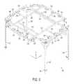
- FIG. 2is a front view of the embodiment of FIG. 1 .
- FIG. 3is a side view of the embodiment of FIG. 1 .
- FIG. 4is a top view of the embodiment of FIG. 1 .
- FIG. 5is a detail perspective view of an example of how the lighting system may be connected to the drilling rig.
- FIG. 6is a perspective view of an exemplary lighting frame according to an embodiment of the invention.
- FIG. 7is a prior art drawing depicting a general drilling rig.
- Crown 100includes a base 105 and an outer frame structure 110 including vertical 115 and horizontal 110 frame members arranged to extend from the base 105 such that the base 105 provides an internal floor to the crown 100 .
- Various drilling rig functional elementsare illustrated, as previously described with respect to FIG. 7 , but these are not described herein in additional detail.
- the inventionis not limited to particular types of drilling rig functional elements and may be used in various drilling rig applications.
- the crown 100 as herein illustrated and describedis an exemplary crown intended to show those features and elements interacting with the lighting system 200 .
- the lighting system in combination with other crown arrangements as are known in the artare equally contemplated by the invention.
- Lighting system 200generally includes a lighting frame 205 (shown in FIG. 6 , and described in more detail herein below), a plurality of light support posts 210 arranged around a perimeter of the lighting frame and extending vertically such that one or more light fixtures 215 , 215 a and 215 b may be connected to each light support post 210 .
- the plurality of light fixtures 215 arranged and separated vertically from each other by their positioning on the light support posts 210permits for light to be directed in a predetermined region proximate the crown 100 and at a predetermined region encompassing a ground area surrounding the drill rig. That is, one group of lights may be directed towards particular equipment on the drilling rig, while another group may be directed to an area surrounding the drilling rig to provide maximum lighting for personnel working in or around the drilling rig.
- an exemplary lighting frame 205includes four corner support posts 220 extending from the base of the crown, or from a position proximate the base of the crown.
- the corner support posts 220prop up, or otherwise raise above the base of the crown an adjustable frame portion 225 .
- the adjustable frame portion 225supports a light bearing frame portion 230 , which will be described in further detail below.
- Adjustable frame portion 225is provided such that the lighting system can be employed on crowns of various sizes.
- Providing the adjustable frame portion 225 in a manner independent of the light bearing frame portion 230permits adjustment of the lighting frame 205 to fit various sized crowns without having to adjust the attachment of the individual lights 215 or adjust the number of lights 215 being attached to the fixture. In this manner, the lighting system can be readily retrofitted to an existing crown for long term use, or moved from one crown to another where short term use is required.
- the adjustable frame portion 225includes along each of its outer portions, a pair of load bearing members 235 rigidly connected to respective corner support posts 220 .
- Each pair of load bearing members 235has positioned therebetween an extendable frame member 240 .
- Each of the load bearing members 235are tubular, such as tubular steel, and are positioned and otherwise arranged such that the extendable frame member 240 extends into the tubular portion of each pair of load bearing members 235 .
- a pin or other protruding element 247is arranged on the load bearing members 235 and is adapted to extend through a hole in the extendable frame member 240 to thereby fix the positioning of the load bearing members 235 with respect to the extendable frame member.
- the load bearing members 235are slidable along the extendable frame member 240 to a desired point, where they can be locked in place by extending the pin 247 through the hole in the extendable frame member 240 , and though a rear portion of the load bearing member 235 to lock the load bearing member 235 with respect to the extendable frame member 240 .
- the frame 205includes four pairs of the load bearing members 235 described above, adjustable about four respective extendable frame members 240 .
- Extendable frame members 240 a and 240 b located on the longer sides of the frame 205include a recess 275 proximate a midpoint thereof, the purpose of which will be described further below.
- a similar recessmay be provided in each of the extendable frame members 240 .
- the light bearing frame portion 230is positioned atop the load bearing members 235 which provide support for the light bearing frame portion 230 .
- the light bearing frame portion 230includes an outer structural frame 243 consisting of a plurality of tubular or solid beams 250 forming a perimeter around which the series of lights are to be mounted.
- the bearing frame portion 243further includes cross-braces 245 holding the structure together, where such cross-braces 245 are preferably perpendicular to a side of the lighting system having a longer length, for example perpendicular to the y axis shown in FIG. 6 .
- Connecting the pair of cross-braces 245are one, and preferably two support braces 260 .
- the support braces 260are positioned internally to the outer structural frame 230 and each have at a midpoint thereof a locating brace 265 connecting the support brace 260 to one member 270 of said outer structural frame 230 .
- a recess 275is provided in the extendable frame members 240 a and 240 b , into which the locating braces 265 are positioned.
- Fixing braces 280connect the outer structural frame members 245 to the extendable frame members 240 along the shorter side of the frame, that is along the x axis of FIG. 6 .
- the adjustable frame portion 225can be installed in a crown of varying sizes while the light bearing frame portion 230 is held centered upon the lighting frame, resulting in it being centered with respect to the crown on which it is placed.
- various addition means for fixing the light bearing portionare also contemplated, including clamps, screws or additional locating pins.
- the light holding platforms 285are preferably welded, or otherwise attached, to the beams 250 .
- the light holding platforms 285generally comprise a portion attaching them to the beams 250 and a portion adapted to hold the light support posts 210 , onto which each of the lights 215 are mounted.
- the portion adapted to hold the light support posts 210includes a recess or hole 290 into which the light support posts 210 can be friction-fit, clamped, screwed into, or otherwise attached. It is also contemplated that the light support posts 210 can be welded into the recess or hole 290 .
- Light support posts 210preferably comprise a vertically extending post onto which a variety of styles of light fixtures 215 may be mounted. As discussed earlier, in a preferred embodiment two light fixtures may be mounted on each light support post 215 , spaced vertically from each other, thus allowing light to be directed to a plurality of key positions around the drilling rig.
- brackets 300may be provided proximate a bottom portion of each corner support post 220 .
- the brackets 300may be adapted to be connected to corresponding brackets (not shown) on the crown 100 or alternatively, to be attached directly to a portion of the crown itself.
- boltsmay fix the brackets 300 directly into a portion of the crown.
Landscapes
- Engineering & Computer Science (AREA)
- General Engineering & Computer Science (AREA)
- Geology (AREA)
- Life Sciences & Earth Sciences (AREA)
- Mining & Mineral Resources (AREA)
- General Life Sciences & Earth Sciences (AREA)
- Fluid Mechanics (AREA)
- Environmental & Geological Engineering (AREA)
- Physics & Mathematics (AREA)
- Geochemistry & Mineralogy (AREA)
- Mechanical Engineering (AREA)
- Non-Portable Lighting Devices Or Systems Thereof (AREA)
- Fastening Of Light Sources Or Lamp Holders (AREA)
- Earth Drilling (AREA)
- Machine Tool Units (AREA)
- Lighting Device Outwards From Vehicle And Optical Signal (AREA)
Abstract
Description
Claims (12)
Priority Applications (8)
| Application Number | Priority Date | Filing Date | Title |
|---|---|---|---|
| US14/093,097US9316390B2 (en) | 2013-11-29 | 2013-11-29 | Lighting system for drilling rig |
| CN201480064226.6ACN105829635B (en) | 2013-11-29 | 2014-07-17 | The lighting system of drilling machine |
| RU2016125743ARU2652514C2 (en) | 2013-11-29 | 2014-07-17 | Lighting system for drilling rig |
| US15/100,140US10125935B2 (en) | 2013-11-29 | 2014-07-17 | Lighting systems for drilling rig |
| MX2016005056AMX2016005056A (en) | 2013-11-29 | 2014-07-17 | Lighting system for drilling rig. |
| PCT/CA2014/050681WO2015077871A1 (en) | 2013-11-29 | 2014-07-17 | Lighting system for drilling rig |
| CA2928251ACA2928251C (en) | 2013-11-29 | 2014-07-17 | Lighting system for drilling rig |
| US14/632,592US10145544B2 (en) | 2013-11-29 | 2015-02-26 | Attachable lighting system for drilling rig |
Applications Claiming Priority (1)
| Application Number | Priority Date | Filing Date | Title |
|---|---|---|---|
| US14/093,097US9316390B2 (en) | 2013-11-29 | 2013-11-29 | Lighting system for drilling rig |
Related Child Applications (2)
| Application Number | Title | Priority Date | Filing Date |
|---|---|---|---|
| US15/100,140ContinuationUS10125935B2 (en) | 2013-11-29 | 2014-07-17 | Lighting systems for drilling rig |
| US14/632,592Continuation-In-PartUS10145544B2 (en) | 2013-11-29 | 2015-02-26 | Attachable lighting system for drilling rig |
Publications (2)
| Publication Number | Publication Date |
|---|---|
| US20150153036A1 US20150153036A1 (en) | 2015-06-04 |
| US9316390B2true US9316390B2 (en) | 2016-04-19 |
Family
ID=53198139
Family Applications (2)
| Application Number | Title | Priority Date | Filing Date |
|---|---|---|---|
| US14/093,097Active - Reinstated2034-05-31US9316390B2 (en) | 2013-11-29 | 2013-11-29 | Lighting system for drilling rig |
| US15/100,140Active2034-06-02US10125935B2 (en) | 2013-11-29 | 2014-07-17 | Lighting systems for drilling rig |
Family Applications After (1)
| Application Number | Title | Priority Date | Filing Date |
|---|---|---|---|
| US15/100,140Active2034-06-02US10125935B2 (en) | 2013-11-29 | 2014-07-17 | Lighting systems for drilling rig |
Country Status (6)
| Country | Link |
|---|---|
| US (2) | US9316390B2 (en) |
| CN (1) | CN105829635B (en) |
| CA (1) | CA2928251C (en) |
| MX (1) | MX2016005056A (en) |
| RU (1) | RU2652514C2 (en) |
| WO (1) | WO2015077871A1 (en) |
Cited By (8)
| Publication number | Priority date | Publication date | Assignee | Title |
|---|---|---|---|---|
| US20150184840A1 (en)* | 2013-11-29 | 2015-07-02 | Apollo Energy Services Corp. | Attachable lighting system for drilling rig |
| WO2017017565A1 (en)* | 2015-07-24 | 2017-02-02 | Apollo Energy Services Corp. | Attachable lighting system |
| US20190242218A1 (en)* | 2016-07-25 | 2019-08-08 | Apollo Energy Services Corp. | Attachable lighting system for drilling rig |
| US10473282B2 (en) | 2018-03-15 | 2019-11-12 | JCA Rentals, LLC | Elevated structure-mounted lighting system |
| US10711961B2 (en) | 2018-03-15 | 2020-07-14 | C&M Oilfield Rentals, Llc | Elevated structure-mounted lighting system |
| RU199442U1 (en)* | 2019-06-04 | 2020-09-01 | Акционерное общество "Омский электромеханический завод" | SPOTLIGHT MAST |
| US10976016B2 (en) | 2018-03-15 | 2021-04-13 | C&M Oilfield Rentals, Llc | Elevated structure-mounted lighting system |
| US11111761B1 (en) | 2016-08-31 | 2021-09-07 | Apollo Energy Services Corp. | Drilling rig with attached lighting system and method |
Families Citing this family (2)
| Publication number | Priority date | Publication date | Assignee | Title |
|---|---|---|---|---|
| US10473310B2 (en)* | 2017-01-04 | 2019-11-12 | Location Illuminator Technologies, LLC | Method and apparatus for illumination of drilling rigs and surrounding locations |
| US11408603B2 (en)* | 2018-04-04 | 2022-08-09 | Cleantek Industries Inc. | Lightweight led lighting systems for permanent and semi-permanent mounting on elevated structures having integrated support and thermal transfer features |
Citations (10)
| Publication number | Priority date | Publication date | Assignee | Title |
|---|---|---|---|---|
| US3827197A (en)* | 1971-10-15 | 1974-08-06 | Eclairage Tech | Masts for supporting projectors |
| US4450507A (en)* | 1982-09-15 | 1984-05-22 | Mycro-Group Company | Composite photometric method |
| US5272609A (en)* | 1992-08-21 | 1993-12-21 | Century Mfg. And Eqpt., Inc. | Portable lighting unit |
| US5432691A (en)* | 1992-11-18 | 1995-07-11 | Vari-Lite, Inc. | Automated truss module with deployment mechanism |
| US5551199A (en)* | 1993-11-08 | 1996-09-03 | Hayes; Jerry R. | Box truss for lights |
| US6607285B2 (en) | 2002-01-18 | 2003-08-19 | Genie Industries, Inc. | Light adjustment apparatus |
| US20050083690A1 (en)* | 2003-10-16 | 2005-04-21 | Farsight Llc | Horizontally and vertically adjustable lighting system and method |
| US20080266859A1 (en)* | 2007-04-26 | 2008-10-30 | Palmisano Lester J | Easy-Glide Offshore Ready Light Tower System |
| WO2012130787A2 (en)* | 2011-03-25 | 2012-10-04 | Nli Engineering As | Derrick apparatus |
| CN203215413U (en) | 2013-03-06 | 2013-09-25 | 中国石油集团渤海石油装备制造有限公司石油机械厂 | Novel lighting lamp support of petroleum drilling machine well site |
Family Cites Families (2)
| Publication number | Priority date | Publication date | Assignee | Title |
|---|---|---|---|---|
| WO2009081382A1 (en)* | 2007-12-22 | 2009-07-02 | Philips Solid-State Lighting Solutions Inc. | Led-based luminaires for large-scale architectural illumination |
| RU121125U1 (en)* | 2012-04-26 | 2012-10-20 | Федеральное Государственное унитарное предприятие Азовский научно-исследовательский институт рыбного хозяйства | UNDERWATER LIGHTING DEVICE FOR RECULTIVATION OF DEEP-WATER BIOCENOSIS |
- 2013
- 2013-11-29USUS14/093,097patent/US9316390B2/enactiveActive - Reinstated
- 2014
- 2014-07-17USUS15/100,140patent/US10125935B2/enactiveActive
- 2014-07-17MXMX2016005056Apatent/MX2016005056A/enunknown
- 2014-07-17WOPCT/CA2014/050681patent/WO2015077871A1/enactiveApplication Filing
- 2014-07-17RURU2016125743Apatent/RU2652514C2/ennot_activeIP Right Cessation
- 2014-07-17CNCN201480064226.6Apatent/CN105829635B/ennot_activeExpired - Fee Related
- 2014-07-17CACA2928251Apatent/CA2928251C/enactiveActive
Patent Citations (11)
| Publication number | Priority date | Publication date | Assignee | Title |
|---|---|---|---|---|
| US3827197A (en)* | 1971-10-15 | 1974-08-06 | Eclairage Tech | Masts for supporting projectors |
| US4450507A (en)* | 1982-09-15 | 1984-05-22 | Mycro-Group Company | Composite photometric method |
| US5272609A (en)* | 1992-08-21 | 1993-12-21 | Century Mfg. And Eqpt., Inc. | Portable lighting unit |
| US5432691A (en)* | 1992-11-18 | 1995-07-11 | Vari-Lite, Inc. | Automated truss module with deployment mechanism |
| US5551199A (en)* | 1993-11-08 | 1996-09-03 | Hayes; Jerry R. | Box truss for lights |
| US6607285B2 (en) | 2002-01-18 | 2003-08-19 | Genie Industries, Inc. | Light adjustment apparatus |
| US20050083690A1 (en)* | 2003-10-16 | 2005-04-21 | Farsight Llc | Horizontally and vertically adjustable lighting system and method |
| US20080266859A1 (en)* | 2007-04-26 | 2008-10-30 | Palmisano Lester J | Easy-Glide Offshore Ready Light Tower System |
| US7988343B2 (en) | 2007-04-26 | 2011-08-02 | Palmisano Jr Lester J | Easy-glide offshore ready light tower system |
| WO2012130787A2 (en)* | 2011-03-25 | 2012-10-04 | Nli Engineering As | Derrick apparatus |
| CN203215413U (en) | 2013-03-06 | 2013-09-25 | 中国石油集团渤海石油装备制造有限公司石油机械厂 | Novel lighting lamp support of petroleum drilling machine well site |
Cited By (15)
| Publication number | Priority date | Publication date | Assignee | Title |
|---|---|---|---|---|
| US20150184840A1 (en)* | 2013-11-29 | 2015-07-02 | Apollo Energy Services Corp. | Attachable lighting system for drilling rig |
| US10145544B2 (en)* | 2013-11-29 | 2018-12-04 | Apollo Energy Services Corp. | Attachable lighting system for drilling rig |
| WO2017017565A1 (en)* | 2015-07-24 | 2017-02-02 | Apollo Energy Services Corp. | Attachable lighting system |
| US20190242218A1 (en)* | 2016-07-25 | 2019-08-08 | Apollo Energy Services Corp. | Attachable lighting system for drilling rig |
| US11846161B2 (en) | 2016-08-31 | 2023-12-19 | Apollo Lighting Solutions Inc. | Drilling rig with attached lighting system and method |
| US11555379B2 (en) | 2016-08-31 | 2023-01-17 | Apollo Lighting Solutions Inc. | Drilling rig with attached lighting system and method |
| US11391121B2 (en) | 2016-08-31 | 2022-07-19 | Apollo Energy Services Corp. | Drilling rig with attached lighting system and method |
| US11111761B1 (en) | 2016-08-31 | 2021-09-07 | Apollo Energy Services Corp. | Drilling rig with attached lighting system and method |
| US10976016B2 (en) | 2018-03-15 | 2021-04-13 | C&M Oilfield Rentals, Llc | Elevated structure-mounted lighting system |
| US10900626B2 (en) | 2018-03-15 | 2021-01-26 | C&M Oilfield Rentals, Llc | Elevated structure-mounted lighting system |
| US10883684B1 (en) | 2018-03-15 | 2021-01-05 | C&M Oilfield Rentals, Llc | Elevated structure-mounted lighting system |
| US10711961B2 (en) | 2018-03-15 | 2020-07-14 | C&M Oilfield Rentals, Llc | Elevated structure-mounted lighting system |
| US11725790B2 (en) | 2018-03-15 | 2023-08-15 | C&M Oilfield Rentals, L.L.C. | Elevated structure-mounted lighting system |
| US10473282B2 (en) | 2018-03-15 | 2019-11-12 | JCA Rentals, LLC | Elevated structure-mounted lighting system |
| RU199442U1 (en)* | 2019-06-04 | 2020-09-01 | Акционерное общество "Омский электромеханический завод" | SPOTLIGHT MAST |
Also Published As
| Publication number | Publication date |
|---|---|
| CA2928251C (en) | 2018-04-24 |
| RU2016125743A (en) | 2018-01-09 |
| CN105829635A (en) | 2016-08-03 |
| US20170023195A1 (en) | 2017-01-26 |
| US20150153036A1 (en) | 2015-06-04 |
| CN105829635B (en) | 2018-06-08 |
| WO2015077871A1 (en) | 2015-06-04 |
| RU2652514C2 (en) | 2018-04-26 |
| CA2928251A1 (en) | 2015-06-04 |
| US10125935B2 (en) | 2018-11-13 |
| MX2016005056A (en) | 2016-12-15 |
Similar Documents
| Publication | Publication Date | Title |
|---|---|---|
| US9316390B2 (en) | Lighting system for drilling rig | |
| US10145544B2 (en) | Attachable lighting system for drilling rig | |
| US11846161B2 (en) | Drilling rig with attached lighting system and method | |
| US8959874B2 (en) | Portable drilling rig apparatus and assembly method | |
| US8555564B2 (en) | Drilling rig assembly method and apparatus | |
| US9091125B2 (en) | Collapsible substructure for a mobile drilling rig | |
| US7527100B2 (en) | Method and apparatus for cutting and removal of pipe from wells | |
| CA2824963C (en) | Method and apparatus for drilling auxiliary holes | |
| US20070251700A1 (en) | Tubular running system | |
| US20190242218A1 (en) | Attachable lighting system for drilling rig | |
| US9217297B2 (en) | Method and support apparatus for supporting down hole rotary tools | |
| ES2967358T3 (en) | Rod rotation apparatus | |
| US11867000B1 (en) | Swivel stand apparatus and associated equipment |
Legal Events
| Date | Code | Title | Description |
|---|---|---|---|
| AS | Assignment | Owner name:AITHRA PROJECTS INCT, CANADA Free format text:ASSIGNMENT OF ASSIGNORS INTEREST;ASSIGNORS:DUPUIS, DARCY;GOWANLOCK, MATTHEW;SIGNING DATES FROM 20140815 TO 20140825;REEL/FRAME:034025/0769 Owner name:APOLLO ENERGY SERVICES CORP., CANADA Free format text:ASSIGNMENT OF ASSIGNORS INTEREST;ASSIGNOR:AITHRA PROJECTS INC;REEL/FRAME:034025/0842 Effective date:20141023 | |
| STCF | Information on status: patent grant | Free format text:PATENTED CASE | |
| FEPP | Fee payment procedure | Free format text:MAINTENANCE FEE REMINDER MAILED (ORIGINAL EVENT CODE: REM.); ENTITY STATUS OF PATENT OWNER: SMALL ENTITY | |
| LAPS | Lapse for failure to pay maintenance fees | Free format text:PATENT EXPIRED FOR FAILURE TO PAY MAINTENANCE FEES (ORIGINAL EVENT CODE: EXP.); ENTITY STATUS OF PATENT OWNER: SMALL ENTITY | |
| PRDP | Patent reinstated due to the acceptance of a late maintenance fee | Effective date:20210129 | |
| FEPP | Fee payment procedure | Free format text:PETITION RELATED TO MAINTENANCE FEES GRANTED (ORIGINAL EVENT CODE: PMFG); ENTITY STATUS OF PATENT OWNER: SMALL ENTITY Free format text:SURCHARGE, PETITION TO ACCEPT PYMT AFTER EXP, UNINTENTIONAL. (ORIGINAL EVENT CODE: M2558); ENTITY STATUS OF PATENT OWNER: SMALL ENTITY Free format text:PETITION RELATED TO MAINTENANCE FEES FILED (ORIGINAL EVENT CODE: PMFP); ENTITY STATUS OF PATENT OWNER: SMALL ENTITY | |
| MAFP | Maintenance fee payment | Free format text:PAYMENT OF MAINTENANCE FEE, 4TH YR, SMALL ENTITY (ORIGINAL EVENT CODE: M2551); ENTITY STATUS OF PATENT OWNER: SMALL ENTITY Year of fee payment:4 | |
| STCF | Information on status: patent grant | Free format text:PATENTED CASE | |
| MAFP | Maintenance fee payment | Free format text:PAYMENT OF MAINTENANCE FEE, 8TH YR, SMALL ENTITY (ORIGINAL EVENT CODE: M2552); ENTITY STATUS OF PATENT OWNER: SMALL ENTITY Year of fee payment:8 |