US9316346B2 - Support system - Google Patents
Support systemDownload PDFInfo
- Publication number
- US9316346B2 US9316346B2US13/024,685US201113024685AUS9316346B2US 9316346 B2US9316346 B2US 9316346B2US 201113024685 AUS201113024685 AUS 201113024685AUS 9316346 B2US9316346 B2US 9316346B2
- Authority
- US
- United States
- Prior art keywords
- support arm
- proximal
- hoop
- mount
- spring
- Prior art date
- Legal status (The legal status is an assumption and is not a legal conclusion. Google has not performed a legal analysis and makes no representation as to the accuracy of the status listed.)
- Active, expires
Links
- 230000008878couplingEffects0.000claimsabstractdescription17
- 238000010168coupling processMethods0.000claimsabstractdescription17
- 238000005859coupling reactionMethods0.000claimsabstractdescription17
- 230000033001locomotionEffects0.000claimsdescription60
- 230000005540biological transmissionEffects0.000claimsdescription26
- 230000006835compressionEffects0.000claimsdescription19
- 238000007906compressionMethods0.000claimsdescription19
- 230000005484gravityEffects0.000claimsdescription4
- 230000007246mechanismEffects0.000abstractdescription17
- 230000000007visual effectEffects0.000abstractdescription2
- 238000000465mouldingMethods0.000description11
- 238000009434installationMethods0.000description9
- 239000003550markerSubstances0.000description5
- 238000005266castingMethods0.000description3
- 239000004033plasticSubstances0.000description2
- 229920003023plasticPolymers0.000description2
- 238000000926separation methodMethods0.000description2
- 229910000831SteelInorganic materials0.000description1
- 230000009471actionEffects0.000description1
- 239000004973liquid crystal related substanceSubstances0.000description1
- 238000004519manufacturing processMethods0.000description1
- 238000005058metal castingMethods0.000description1
- 238000000034methodMethods0.000description1
- 230000008569processEffects0.000description1
- 230000009467reductionEffects0.000description1
- 239000010959steelSubstances0.000description1
Images


Classifications
- F—MECHANICAL ENGINEERING; LIGHTING; HEATING; WEAPONS; BLASTING
- F16—ENGINEERING ELEMENTS AND UNITS; GENERAL MEASURES FOR PRODUCING AND MAINTAINING EFFECTIVE FUNCTIONING OF MACHINES OR INSTALLATIONS; THERMAL INSULATION IN GENERAL
- F16M—FRAMES, CASINGS OR BEDS OF ENGINES, MACHINES OR APPARATUS, NOT SPECIFIC TO ENGINES, MACHINES OR APPARATUS PROVIDED FOR ELSEWHERE; STANDS; SUPPORTS
- F16M13/00—Other supports for positioning apparatus or articles; Means for steadying hand-held apparatus or articles
- F16M13/02—Other supports for positioning apparatus or articles; Means for steadying hand-held apparatus or articles for supporting on, or attaching to, an object, e.g. tree, gate, window-frame, cycle
- F—MECHANICAL ENGINEERING; LIGHTING; HEATING; WEAPONS; BLASTING
- F16—ENGINEERING ELEMENTS AND UNITS; GENERAL MEASURES FOR PRODUCING AND MAINTAINING EFFECTIVE FUNCTIONING OF MACHINES OR INSTALLATIONS; THERMAL INSULATION IN GENERAL
- F16M—FRAMES, CASINGS OR BEDS OF ENGINES, MACHINES OR APPARATUS, NOT SPECIFIC TO ENGINES, MACHINES OR APPARATUS PROVIDED FOR ELSEWHERE; STANDS; SUPPORTS
- F16M11/00—Stands or trestles as supports for apparatus or articles placed thereon ; Stands for scientific apparatus such as gravitational force meters
- F16M11/02—Heads
- F16M11/04—Means for attachment of apparatus; Means allowing adjustment of the apparatus relatively to the stand
- F16M11/06—Means for attachment of apparatus; Means allowing adjustment of the apparatus relatively to the stand allowing pivoting
- F16M11/12—Means for attachment of apparatus; Means allowing adjustment of the apparatus relatively to the stand allowing pivoting in more than one direction
- F16M11/126—Means for attachment of apparatus; Means allowing adjustment of the apparatus relatively to the stand allowing pivoting in more than one direction for tilting and panning
- F—MECHANICAL ENGINEERING; LIGHTING; HEATING; WEAPONS; BLASTING
- F16—ENGINEERING ELEMENTS AND UNITS; GENERAL MEASURES FOR PRODUCING AND MAINTAINING EFFECTIVE FUNCTIONING OF MACHINES OR INSTALLATIONS; THERMAL INSULATION IN GENERAL
- F16M—FRAMES, CASINGS OR BEDS OF ENGINES, MACHINES OR APPARATUS, NOT SPECIFIC TO ENGINES, MACHINES OR APPARATUS PROVIDED FOR ELSEWHERE; STANDS; SUPPORTS
- F16M11/00—Stands or trestles as supports for apparatus or articles placed thereon ; Stands for scientific apparatus such as gravitational force meters
- F16M11/20—Undercarriages with or without wheels
- F16M11/2007—Undercarriages with or without wheels comprising means allowing pivoting adjustment
- F16M11/2035—Undercarriages with or without wheels comprising means allowing pivoting adjustment in more than one direction
- F16M11/2064—Undercarriages with or without wheels comprising means allowing pivoting adjustment in more than one direction for tilting and panning
- F—MECHANICAL ENGINEERING; LIGHTING; HEATING; WEAPONS; BLASTING
- F16—ENGINEERING ELEMENTS AND UNITS; GENERAL MEASURES FOR PRODUCING AND MAINTAINING EFFECTIVE FUNCTIONING OF MACHINES OR INSTALLATIONS; THERMAL INSULATION IN GENERAL
- F16M—FRAMES, CASINGS OR BEDS OF ENGINES, MACHINES OR APPARATUS, NOT SPECIFIC TO ENGINES, MACHINES OR APPARATUS PROVIDED FOR ELSEWHERE; STANDS; SUPPORTS
- F16M13/00—Other supports for positioning apparatus or articles; Means for steadying hand-held apparatus or articles
- F16M13/02—Other supports for positioning apparatus or articles; Means for steadying hand-held apparatus or articles for supporting on, or attaching to, an object, e.g. tree, gate, window-frame, cycle
- F16M13/022—Other supports for positioning apparatus or articles; Means for steadying hand-held apparatus or articles for supporting on, or attaching to, an object, e.g. tree, gate, window-frame, cycle repositionable
- H—ELECTRICITY
- H05—ELECTRIC TECHNIQUES NOT OTHERWISE PROVIDED FOR
- H05K—PRINTED CIRCUITS; CASINGS OR CONSTRUCTIONAL DETAILS OF ELECTRIC APPARATUS; MANUFACTURE OF ASSEMBLAGES OF ELECTRICAL COMPONENTS
- H05K5/00—Casings, cabinets or drawers for electric apparatus
- H05K5/02—Details
- H05K5/0204—Mounting supporting structures on the outside of casings
- F—MECHANICAL ENGINEERING; LIGHTING; HEATING; WEAPONS; BLASTING
- F16—ENGINEERING ELEMENTS AND UNITS; GENERAL MEASURES FOR PRODUCING AND MAINTAINING EFFECTIVE FUNCTIONING OF MACHINES OR INSTALLATIONS; THERMAL INSULATION IN GENERAL
- F16M—FRAMES, CASINGS OR BEDS OF ENGINES, MACHINES OR APPARATUS, NOT SPECIFIC TO ENGINES, MACHINES OR APPARATUS PROVIDED FOR ELSEWHERE; STANDS; SUPPORTS
- F16M2200/00—Details of stands or supports
- F16M2200/02—Locking means
- F16M2200/021—Locking means for rotational movement
- F16M2200/022—Locking means for rotational movement by friction
- F—MECHANICAL ENGINEERING; LIGHTING; HEATING; WEAPONS; BLASTING
- F16—ENGINEERING ELEMENTS AND UNITS; GENERAL MEASURES FOR PRODUCING AND MAINTAINING EFFECTIVE FUNCTIONING OF MACHINES OR INSTALLATIONS; THERMAL INSULATION IN GENERAL
- F16M—FRAMES, CASINGS OR BEDS OF ENGINES, MACHINES OR APPARATUS, NOT SPECIFIC TO ENGINES, MACHINES OR APPARATUS PROVIDED FOR ELSEWHERE; STANDS; SUPPORTS
- F16M2200/00—Details of stands or supports
- F16M2200/04—Balancing means
- F16M2200/041—Balancing means for balancing rotational movement of the head
- F—MECHANICAL ENGINEERING; LIGHTING; HEATING; WEAPONS; BLASTING
- F16—ENGINEERING ELEMENTS AND UNITS; GENERAL MEASURES FOR PRODUCING AND MAINTAINING EFFECTIVE FUNCTIONING OF MACHINES OR INSTALLATIONS; THERMAL INSULATION IN GENERAL
- F16M—FRAMES, CASINGS OR BEDS OF ENGINES, MACHINES OR APPARATUS, NOT SPECIFIC TO ENGINES, MACHINES OR APPARATUS PROVIDED FOR ELSEWHERE; STANDS; SUPPORTS
- F16M2200/00—Details of stands or supports
- F16M2200/04—Balancing means
- F16M2200/044—Balancing means for balancing rotational movement of the undercarriage
- F—MECHANICAL ENGINEERING; LIGHTING; HEATING; WEAPONS; BLASTING
- F16—ENGINEERING ELEMENTS AND UNITS; GENERAL MEASURES FOR PRODUCING AND MAINTAINING EFFECTIVE FUNCTIONING OF MACHINES OR INSTALLATIONS; THERMAL INSULATION IN GENERAL
- F16M—FRAMES, CASINGS OR BEDS OF ENGINES, MACHINES OR APPARATUS, NOT SPECIFIC TO ENGINES, MACHINES OR APPARATUS PROVIDED FOR ELSEWHERE; STANDS; SUPPORTS
- F16M2200/00—Details of stands or supports
- F16M2200/06—Arms
- F16M2200/065—Arms with a special structure, e.g. reinforced or adapted for space reduction
Definitions
- the present inventionis concerned with a support system.
- Particular embodiments of the inventionare concerned with a moveable support arm for a monitor or display device.
- Modern screen-based display devicesare typically flat-screen monitors such as liquid crystal display (LCD) or plasma screen displays. Such devices can be mounted on elevated support devices such as a support arm which can then be secured to a surface such that the flat-screen monitor is held above or in front of the surface.
- LCDliquid crystal display
- plasma screen displaysSuch devices can be mounted on elevated support devices such as a support arm which can then be secured to a surface such that the flat-screen monitor is held above or in front of the surface.
- known arrangementssuch as those disclosed in GB 2 438 581 and U.S. Pat. No. 7,438,269 have a second pivoting mechanism entirely separate from the first.
- the second pivotis a separate vertical rod-like element defining a vertical axis. This second pivot is distinct and separated from the pivot of the arcuate connector.
- Support systems for monitorscomprising an articulated arm arrangement for raising and lowering a monitor are known with tiltable mount or bracket mechanisms which keep the monitor in the same plane as the arm moves up and down.
- the known arrangementssuch as those disclosed in US 2004/0245419 have a four bar linkage or parallelogram arrangement in which there is a second link or arm below (or above) and parallel to the main support arm and pivotally coupled to the tiltable mount or bracket on which a monitor is mounted.
- the second link or armis pivotally coupled to the mount or bracket below (or above) the pivot between the main support arm and the mount, and also pivotally coupled to the base or support element to which the other end of the main support arm is pivotally coupled at a point below (or above) the pivot between the main support arm and the base or support element.
- the main support arm and the second link armare parallel to each other and the linkage (which can be considered to be a line drawn between) the pairs of pivots on each of the base element and mount are also parallel to each other.
- This parallelogram four-bar linkagemeans that as the support arm is moved up and down the linkage between the two pivots on the tilt mount remains in the same plane parallel to the linkage between the two pivots on the base element.
- a disadvantage of the known four-bar parallelogram linkage arrangementsis the need to provide a second link parallel to and separate from the support arm. Such arrangements therefore must have a second visible (and therefore unsightly) link or arm parallel to the main support arm.
- Such parallelogram arrangementshave a large deep casing which can house the main support arm, the second parallel link and the space therebetween. This is bulky and therefore also unsightly.
- the installation technicianmanually adjusts the position of an end of the spring using trial and error until the torque provided by the weight of the monitor is balanced by the torque from the spring and the monitor can be moved easily and yet remains in position when positioned at a particular elevation by an operator.
- the process of such manual installationis particularly cumbersome and time consuming when a large number of monitors and support arms are being installed as is often the case when, for example, an office is being fitted out with a number of identical monitors and support arms.
- one embodiment of a support systemprovides a single simple mechanism which allows adjustment about two orthogonal pivots. This mechanism is easier and cheaper to make than the know arrangements and is aesthetically more pleasing.
- a support systemeliminates the need for a second parallel link separated from the first and a vertical separation between the two parallel links. This second aspect therefore allows for a more compact and aesthetically pleasing support arm which keeps its load mount in the same plane as the support arm moves up and down.
- a support systemprovides alternative arrangements for varying the torque applied to oppose the variations in torque resulting as the support arm is pivoted about a horizontal axis.
- One embodiment of the third aspectprovides a mechanism which allows the variations in torque provided by the support arm as its pivots and which opposes the weight of a load on the support arm to better match the variations in torque provided by the weight as the support arm pivots.
- the inventors of the subject applicationare the first to realize that taking the step of moving the proximal force transmission link pivot away from its usual position on the line through the proximal support arm pivot and substantially orthogonal to the longitudinal axis of the support arm when this is at the mid-point of its range of movement about the proximal support arm pivot allows one to better match the shape of the graphs of variation in supporting torque and load weight torque with support arm movement to each other and hence better support a load on the support arm.
- the inventorsare the first to appreciate that the counter-intuitive step of moving away from the essentially symmetrical proximal support arm pivot and proximal force transmission pivot arrangement of the prior art actually allows one to produce a more symmetrical variation in supporting torque to better match load weight torque.
- a mechanismreduces undesirable variations in the dimensions, and hence compression or expansion, of the spring. This reduction in the undesirable variations means that the forces produced by the spring as the support arm moves better match the torque required to support a load weight on the distal end of the support arm.
- the inventors of the invention described in this applicationalso have appreciated that it possible to significantly reduce the time taken to install a number of identical monitors and support arm arrangements by providing a mechanism for copying or carrying over the adjustment necessary for a first installation to other further installations without the need for further time consuming trial and error based manual adjustment.
- Embodiments of this support armallow an installation operative to note what adjustment was necessary for a particular support arm and monitor combination and then carry over that noted level of adjustment to further installations of the same pair of support arm and monitor type.
- the balancing mechanismis a resilient member acting against a movable biasing surface and the adjustment mechanism adjusts the position of the biasing surface and thereby alters the force exerted by the resilient member against the biasing surface, and the indicator arrangement indicates the position of the biasing surface.
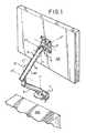
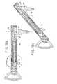
- FIG. 1is a perspective view of a first embodiment of the support device
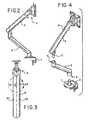
- FIG. 2is a side view of the support device of FIG. 1 ;
- FIG. 3is a top view of the support device of FIG. 1 ;
- FIG. 4is a partially exploded view of the support device of FIGS. 1 to 3 ;
- FIG. 5is an exploded view of the upper arm of the support device of FIGS. 1 to 4 ;
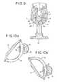
- FIG. 6is a perspective view of the mounting and movement head of the device of FIGS. 1 to 5 ;
- FIG. 7is a partially exploded view of portions of the mounting and movement head of FIG. 6 ;
- FIG. 8is an exploded view of the upper end of the upper arm and the mounting and movement head of FIGS. 1 to 6 ;
- FIG. 9is a cross-sectional view of aspects of the mounting and movement head along section IX-IX in FIG. 2 ;
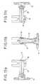
- FIGS. 10 a and 10 bare cross-sectional views along part of section X-X in FIG. 3 illustrating adjustment of the mounting and movement head in a first plane;
- FIGS. 11 a to 11 care top views of the mounting and movement head illustrating adjustment of the mounting and movement head in a second plane orthogonal to the plane of the section of FIGS. 10 a and 10 b;
- FIGS. 12 a to 12 care cross-sectional views along part of section X-X of FIG. 3 which illustrate the invention in its second aspect as the upper support arm pivots;
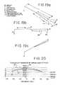
- FIGS. 13 and 14illustrate the variation in torque created about the pivot on the bottom end of the upper arm of FIGS. 1 to 13 by the weight of, for example, a monitor mounted at its upper end, as the support arm pivots about that pivot at its bottom end;
- FIGS. 15 to 17illustrate how the torque of FIGS. 13 and 14 is opposed in known support device arrangements
- FIGS. 18 a to 18 care cross-sectional views similar to those of FIGS. 12 a to 12 c illustrating the invention in its third aspect;
- FIGS. 19 and 20illustrate how the torque created at the pivot by the weight of a load o on the lower end of the upper support arm is opposed in the arrangement of FIGS. 1 to 12, and 18 ;
- FIGS. 21 a and 21 billustrate a detail at the bottom end of the upper support arm in an alternative embodiment of the invention
- FIGS. 22 a to 22 care cross-sectional views along section XXI-XXI in FIG. 21 a illustrating the invention in its fourth aspect;
- FIG. 23is an enlarged, partial cross-sectional view of a support arm taken along line 23 of FIG. 18 b;
- FIG. 24is an enlarged, partial top view of a support arm taken along line 24 of Figure;
- FIG. 25is an enlarged, top view of an alternative embodiment of an indicator window arrangement.
- FIG. 26is an enlarged, top view of another alternative embodiment of an indicator window arrangement.
- FIG. 27is an enlarged, top view of another alternative embodiment of an indicator window arrangement.
- FIG. 28is an enlarged, top view of another alternative embodiment of an indicator window arrangement.
- a support device 1includes a base element, including a table securing element 2 and a lower arm 3 , an upper arm 4 , a monitor mounting head and pivot 5 , and a monitor plate 6 , or device mounting element, for securing to the back of a monitor 201 to be supported.
- the table securing element 2has a screw or clamp arrangement for removably securing the element 2 to a table or other surface 203 and an upstanding pin 7 received within a corresponding hole 8 in the end of the lower arm 3 such that the lower arm 3 can rotate about a vertical Y′ axis (see FIG. 1 ) relative to the table securing element 2 .
- the lower arm 3then has a hole or female coupling 9 at its upper end to receive a pin or male coupling 10 at the bottom end of the upper arm 4 .
- the upper arm 4can rotate about a vertical axis Y′′ (see FIG. 1 ) relative to the lower arm 3 by virtue of this pin and hole engagement.
- the lower arm 3can rotate relative to the table securing element 2 about a vertical axis Y′
- the upper arm 4can rotate relative to the lower arm 3 about a vertical axis Y′′ and a horizontal axis X′′
- the mounting head 5can rotate relative to the distal end of the upper support arm 4 about two orthogonal axes (one substantially horizontal axis X′′′ and the other substantially vertical axis Y′′′).
- the monitor supporting head 5can also rotate about a horizontal axis Z′′′ orthogonal to the X′′′ and Y′′′ axes.
- the mounting head 5comprises a movement joint hoop 11 with a fixing portion 12 for slidable engagement with the monitor supporting plate 6 , and a hoop portion 13 of substantially circular cross-section.
- a motion joint 14 with an internal circular bearing surface 15 corresponding to the circumference of the hoop 13is positioned on the hoop 13 and can move along the hoop and rotate around the hoop.
- the motion joint 14is a two-part plastics moulding. The plastics moulding is held between two projecting portions 16 at the distal end of the upper support arm 4 .
- Slotted screws 17in combination with the portions 16 defining a distal support arm pivot, apply pressure to the outside of each side of the moulding via rectangular nuts and Belleville washers 18 so that the motion joint is frictionally engaged on the hoop.
- the projecting arms 16can rotate relative to the motion joint 14 such that the support arm can rotate about horizontal axis X′′′. Projecting portions 60 on the inside of the upper arm projections 16 engage a track 61 on the motion joint 14 to allow this relative rotation about axis X′′′.
- the support device 1includes movement joint hoop 11 , distal front link pivot pin 19 , proximal front link pivot pin 42 , motion joint moulding left half 20 , motion joint adjustment screws 17 , Belleville washers 18 , front link 21 , thin hex nut 22 , mid joint button screws 23 , upper arm casting left half 24 , spring slider moulding left half 25 , friction pad 26 , anti-finger trap moulding 27 , power link 28 , mid joint pivot pin 29 , force adjustment screw 30 , mid joint 31 , steel washer 32 , spring slider moulding right half 34 , compression spring 35 , head screw 36 , upper arm casting right half 37 , rectangular nuts 38 , motion joint moulding right half 39 , spring nut plate 40 and cable management clip 41 .
- the motion joint 14can move relative to the hoop 13 .
- movement of the motion joint along the hoopwe will usually refer to movement of the motion joint along the hoop.
- This expressionrefers to relative movement in a direction along the curvature of the hoop and includes movement of the motion joint with the hoop remaining still, movement of the hoop with the motion joint remaining still and movement of both the motion joint and hoop.
- the hoop 13lies on the circumference of a circle whose centre lies at or near the centre of gravity of the monitor or other element being supported on the mounting head. This reduces the magnitude of the frictional force which the bearing surfaces 15 of the motion joint must apply to the hoop in order to hold its position on the hoop.
- the motion joint 14can also rotate relative to the hoop 13 and a combination of the movement along and about the hoop means that the, for example, monitor 201 on the mounting head 5 , can be rotated about orthogonal X′′′ and Y′′′ axes.
- rotation of the motion joint about the hoopThis expression refers to relative rotation about a curved axis running down the middle of the hoop and includes rotation of the motion joint with the hoop remaining still, rotation of the hoop with the motion joint remaining still and rotation of both the motion joint and hoop.
- the mount fixing portion 12is held in a turntable like portion of the monitor supporting plate 6 such that the monitor supporting plate 6 can rotate relative to the mount fixing portion 12 about axis Z′′′ (see FIG. 1 ).
- the upper support arm 4is a two-part metal casting whose two halves 24 , 37 are held together by a screw and nut coupling 36 , 22 towards the distal end of the upper support arm and a pair of proximal mid-joint button screws 23 which each pass through a pair of holes in the upper end of the mid joint 31 and engage opposite ends of the mid joint pivot pin 29 , which defines a proximal support arm pivot, so that the upper support arm 4 can pivot about that mid joint pivot pin 29 and hence about horizontal axis X′′ (see FIG. 1 ).
- the distal end of each half of the upper support end casingforms one half 16 of a U-shaped motion joint fixing portion so that together the two halves of the casting capture the motion joint 14 as described above (see FIGS.
- An upper support arm front link 21 or distal slider linkis mounted at its distal end on the distal front link pivot 19 held between the two halves 20 , 39 of the motion joint 14 and at its proximal end on a proximal front link pivot pin 42 pivotally mounted on the distal end of a sliding carriageway or spring slider 43 supported within the upper arm casing.
- the spring slider 43or slider element, is a two-part moulding 25 , 34 and the proximal front link pivot pin 42 is held between the distal ends of the two halves to support the front link 21 .
- the spring slider 43has a compression spring 35 (not shown in FIGS. 12 a to 12 c ) inside it which engages at its distal end with a spring nut plate 40 , which defines a moveable spring surface, mounted on the distal end of a force adjusting screw 30 .
- the force adjustment screwis set to define a particular separation between the spring nut plate 40 and the proximal end of the spring slider 43 . This defines the length of the space for the compression spring 35 and hence determines the force supplied by the spring 35 , or force generating member.
- the force adjusting screw 30can adjust the position of the spring nut plate 40 within the spring slider moulding and thereby increase or decrease the length of the compression spring and hence, respectively, decrease or increase the force that spring will apply to the spring slider and spring nut plate, and hence to the rear power link 28 , otherwise referred to as a proximal slide link or a force transmission link, pivotally connected to the proximal end of the spring slider 43 against which the proximal end of the spring 35 acts.
- the two casing halves 24 , 37each have indents 50 which, when the upper arm is assembled, together define an indicator window 51 into which a lens is fitted.
- the spring nut plate 40When assembled (see FIGS. 23-26 ) the spring nut plate 40 is visible through the indicator window 51 , and functions as a marker.
- the indicator windowincludes markings 153 , or indicia, positioned adjacent the marker, for example on the lens. Alternatively, the markings may be positioned on the casing adjacent the window.
- the visible spring nut plate 40acts as a marker and combines with the indicia 153 provide an indication of the position of the spring nut plate, and hence the spring force applied by the spring 35 .
- the spring nut plate 40alone, as viewed through the window 51 , may provide the requisite indicia, by noting the relative position of the marker in the window (see, e.g., FIG. 26 ).
- the position of the spring nut plate 40provides a measure of the length of the spring 35 and hence of the biasing and the spring force provided by the spring.
- the indiciamay take the form of alpha-numeric characters, such as numbers or letters (see, e.g., FIG. 24 ), or various symbols, such as dots or lines (see, e.g., FIG. 25 ), such that the installer can note the relative position of the marker to the indicia.
- the position of the spring nut plate 40is adjusted by the force adjusting screw 30 , and moves in the window 51 , until the torque produced by the weight of the display device or monitor matches the torque provided by the spring 35 at all orientations of the display device.
- the display device or monitorshould feel like it is floating at all orientations.
- the best orientation for adjustmentis as shown in FIG. 22 b ; the back of the monitor is at 90° to the upper support arm which is itself at 90° to the lower support arm. This position allows for easier and more precise adjustment.
- An installationoperative places the monitor and support arm in the position shown in FIGS. 22 a - c and then adjusts the force adjustment screw 30 using a screwdriver or Allen (or hex) key 54 by trial and error until the torques are balanced and the monitor floats in all monitor height positions.
- the operativethen reads off the indication setting of the first installed arm by noting the position of the spring nut plate 40 in the indicator window relative to the markings.
- the read and noted indicator settingscan then be used as the initial setting for further similar installations. Further trial and error may be necessary to fine tune any such further installations.
- the rear power link 28is arranged between the proximal end of the spring slider 43 and the mid-joint 31 so as to transmit the force from the compression spring 35 to the mid-joint 31 .
- the rear power link 28is connected to the spring slider 43 at the rear power link's distal end by a distal rear link pivot pin 44 , defining a distal force transmission link pivot, held between the two moulding halves 25 , 34 of the spring slider 43 and is connected to the mid-joint 31 by a proximal rear link pivot pin 45 , defining a proximal force transmission link pivot, held between two upstanding portions 46 of the U-shaped mid-joint 31 .
- the rear power link proximal pivot 45is located on the mid-joint below the upper arm pivot point 29 and at a position forward or distal from the vertical axis passing through that support arm pivot point 29 .
- the combination of the support arm outer casing 47 pivotally coupled at its proximal end to the mid-joint 31 and at its distal end to the motion joint 14 , combined with the internal slider 43 coupled at its distal end via the front link 21 and at its proximal end via the rear power link 28means that a monitor supported on the mounting head remains in substantially the same plane as the upper support arm 4 pivots about the mid-joint 31 in the manner shown in FIGS. 12 a , 12 b and 12 c.
- the rear power link 28pushes the slider 43 in the support arm casing 47 towards the motion joint 14 . This then causes the front link 21 to push its pivot point on the motion joint forward.
- the upper support arm 4in order to raise and/or lower a monitor (not shown) fixed to the mounting head 14 relative to the lower arm 3 and hence the table surface on which the support device 1 is mounted, the upper support arm 4 can be rotated from its highest position (see FIG. 12 a ), approximately 45 degrees above the horizontal down to its lowest position (see FIG. 11 c ), approximately 45 degrees below the horizontal.
- the spring 35 inside the support arm 4acts on the mid-joint 31 via the rear link 28 to produce a torque which counter-acts the torque produced by the weight of the monitor.
- the maximum distance and hence torqueis when the arm is horizontal (see FIGS. 12 b and 13 b ) and at its minimum when in its uppermost (see FIGS. 12 a and 13 a ) and lowermost (see FIGS. 12 c and 13 c ) positions.
- the distance of the monitor from its centre of gravity to the mid-joint pivot Pis at its greatest when the upper support arm is horizontal ( FIG. 13 b ) and lowest when the monitor is in either its uppermost ( FIG. 13 a ) or lowermost ( FIG. 13 c ) positions.
- the torque at the mid joint pivot 29 (P in FIGS. 13 and 14 ) created by the monitor weightis at a maximum when the arm angle to the horizontal is 0° and at a minimum at the ends of its range of movement which are +45° and ⁇ 45° in the illustrated example.
- the graph of FIG. 14is an illustration of the magnitude of the torque at P (i.e. pivot point 29 ) created by a monitor weight which assumes a monitor weight of 40N, an arm length of 265 mm and a range of movement of +/ ⁇ 45° from the horizontal.
- the known arrangementsfor opposing the torque created at the pivot point 29 by the load at the distal end of the support arm use a spring force G created by either a mechanical spring or gas spring inside the upper support arm 4 .
- This spring force Gis transmitted via a rear power link 151 of length f which acts through proximal rear link pivot point 152 at a distance d vertically below the main support arm pivot point P (or 29 ).
- the torque T at P generated by the spring force Gis the product of the force S in the rear link 151 and the distance d. Force S is equal to the component of spring force G along the direction of the rear power link.
- the variation in Tis as shown in FIG. 15 by the constant force line 65 .
- the torque Tvaries as the support arm pivots because the component of the spring force G along the direction of the rear power link 151 varies as this pivots relative to the upper support and the direction of the spring force G.
- the torque created by the constant spring force in the known arrangement of FIG. 14does not vary in the same way as the torque created by the weight of the load W (line 66 in graph).
- the peak weight opposing torque 62i.e.
- the torque produced by the spring force Gis not at the same position as the peak torque created by the load weight. Furthermore, if the spring force is created by a mechanical spring such as a compression spring, the differences are even greater (see FIG. 16 wherein the variation in torque from a compression spring is line 67 )). This is because the magnitude of the spring force G varies as the spring is compressed to varying degrees as the upper support arm rotates.
- the torque produced by the weight of the monitor(see FIGS. 18 and 19 ) is opposed by a torque which is the product of the spring force created by the compression spring 35 in the rear power link 28 and the perpendicular distance e between the line of that force and the proximal power link pivot 45 .
- the proximal rear power link pivot pin 44 of the described embodiment of the inventionis located forward (or distal) from the axis W (see FIG. 18 b ) through the mid-joint pivot 29 which is orthogonal to the longitudinal axis of the upper support arm at the mid point of range of movement of the upper support arm; i.e. the proximal rear link pivot 44 is forward of a vertical axis through the mid-joint pivot 29 when the upper support arm can move between +/ ⁇ 45° to the horizontal.
- proximal pivot 45 for the rear link at a position forward or distal from the verticalwas through the proximal support arm pivot 29 (i.e. forward or distal from an axis through the pivot 29 and orthogonal to the support arm longitudinal axis at the mid-point of the range of movement of the support arm about axis X′′ (i.e. position shown in FIG. 12 b ) means that the perpendicular distance d varies in a manner which is closer to the variation in the torque caused by the weight of the monitor than is the case in the known arrangements which have the rear link pivot point in line with a vertical line through the proximal support arm pivot (where the mid-point of the range of movement is the horizontal).
- the mid-point of the range of movement of the support arm about axis X′′is the horizontal so that the relevant axis through the pivot 29 is vertical.
- the relevant axis through the proximal pivot support arm 29might not be vertical.
- FIGS. 18 a to 18 cas the support arm 4 rotates from its uppermost position (see FIG. 18 a ), through the mid-position (see FIG. 18 b ) down to its lowermost position ( 18 c ), the rear power link 28 progressively compresses the spring 35 by pushing it against the fixed spring nut plate 40 . This means that the force provided by the spring 35 progressively increases as the support arm 4 is lowered in a manner similar to that discussed above in connection with FIG. 17 .
- the increasing spring force which results as the spring 35 is compressed as illustrated in FIGS. 18 a to 18 c as the support arm moves from its uppermost (see FIG. 22 a ) to is lowermost (see FIG. 22 c ) position and progressively compresses the spring 35 furtheris modified or controlled by modifying or controlling the degree of compression of the spring inside the support arm 4 so as to optimise or improve the spring load relative to the variations in the torque created by the monitor weight as the support arm moves through its range of movement about the horizontal axis X′′.
- the force adjusting screw 30is held by a screw holding element 52 rather than then end of the support arm casing as in the embodiment of FIGS. 1 to 12 and 18 .
- This screw holding element 52is connected to the mid-joint 31 by a spring adjustment link 53 , or compensation link, which is itself connected at its ends to the mid joint and screw holding element by pivot pins 54 , defining compensation link distal and proximal pivots.
Landscapes
- Engineering & Computer Science (AREA)
- General Engineering & Computer Science (AREA)
- Mechanical Engineering (AREA)
- Microelectronics & Electronic Packaging (AREA)
- Devices For Indicating Variable Information By Combining Individual Elements (AREA)
- Manipulator (AREA)
Abstract
Description
The present invention is concerned with a support system. Particular embodiments of the invention are concerned with a moveable support arm for a monitor or display device.
Modern screen-based display devices are typically flat-screen monitors such as liquid crystal display (LCD) or plasma screen displays. Such devices can be mounted on elevated support devices such as a support arm which can then be secured to a surface such that the flat-screen monitor is held above or in front of the surface.
Support systems for monitors are known which allow for movement in three dimensions of the head, mount or bracket on which the monitor is mounted. This is so as to allow for a full range of adjustment of the monitor.GB 2 438 581 and U.S. Pat. No. 7,438,269 both disclose mounts or brackets including an arcuate connection which allows a monitor to be pivoted about a substantially horizontal virtual pivot axis. In U.S. Pat. No. 7,438,269, the virtual pivot axis passes through the centre of gravity of a monitor or display so as to reduce the forces necessary to hold the mount in place at a selected position on the arcuate connection.
In order to allow for adjustment about a substantially vertical axis (or an axis orthogonal to the axis of the arcuate connection), known arrangements such as those disclosed inGB 2 438 581 and U.S. Pat. No. 7,438,269 have a second pivoting mechanism entirely separate from the first. The second pivot is a separate vertical rod-like element defining a vertical axis. This second pivot is distinct and separated from the pivot of the arcuate connector.
These prior art arrangements require two separate and distinct pivot arrangements. They are therefore relatively complicated and expensive to build, have two pivots (and therefore more moving parts) which can fail and are relatively unsightly.
Support systems for monitors comprising an articulated arm arrangement for raising and lowering a monitor are known with tiltable mount or bracket mechanisms which keep the monitor in the same plane as the arm moves up and down. The known arrangements such as those disclosed in US 2004/0245419 have a four bar linkage or parallelogram arrangement in which there is a second link or arm below (or above) and parallel to the main support arm and pivotally coupled to the tiltable mount or bracket on which a monitor is mounted. The second link or arm is pivotally coupled to the mount or bracket below (or above) the pivot between the main support arm and the mount, and also pivotally coupled to the base or support element to which the other end of the main support arm is pivotally coupled at a point below (or above) the pivot between the main support arm and the base or support element. The main support arm and the second link arm are parallel to each other and the linkage (which can be considered to be a line drawn between) the pairs of pivots on each of the base element and mount are also parallel to each other.
This parallelogram four-bar linkage means that as the support arm is moved up and down the linkage between the two pivots on the tilt mount remains in the same plane parallel to the linkage between the two pivots on the base element.
A disadvantage of the known four-bar parallelogram linkage arrangements is the need to provide a second link parallel to and separate from the support arm. Such arrangements therefore must have a second visible (and therefore unsightly) link or arm parallel to the main support arm. Alternatively, such parallelogram arrangements have a large deep casing which can house the main support arm, the second parallel link and the space therebetween. This is bulky and therefore also unsightly.
Another problem with articulated support arms for loads such as monitors or display devices which move up and down as they pivot about a horizontal axis, is the varying torque created by the constant weight of the monitor applied about the horizontal axis. As the arm moves up and down the distance from the load at the end of the support arm to the other end of the support arm and the pivot between the support arm and its base varies.
In order to oppose this varying torque it is known (see, for example, US 2004/0245419) to provide a compression spring which provides a variable force to create a torque to oppose and match the torque created by the weight of the load. The spring is subject to a cam arrangement which controls the degree of compression of the spring and hence the force it applies. Cam arrangements of the type disclosed in US 2004/0245419 are relatively complex and hence expensive to make.
Another problem with arrangements in which a biased mechanical spring, gas spring or other biasing element provides the force necessary to balance the weight of the monitor is the need to set up or adjust the spring or biasing element when a monitor is placed on it so that the torque provided by the spring closely hatches the torque provided by the weight of the monitor. This is done by a manual adjustment of the spring position of a surface against which the spring rests for a compression or expansion spring, and for a gas spring (which provides a constant force) by adjustment of the orientation and position of the end of the gas spring relative to the monitor mount, monitor and principal longitudinal axis of the support arm (i.e. the geometry of the lines of application of the various forces/torques is adjusted to achieve balance).
The installation technician manually adjusts the position of an end of the spring using trial and error until the torque provided by the weight of the monitor is balanced by the torque from the spring and the monitor can be moved easily and yet remains in position when positioned at a particular elevation by an operator. The process of such manual installation is particularly cumbersome and time consuming when a large number of monitors and support arms are being installed as is often the case when, for example, an office is being fitted out with a number of identical monitors and support arms.
In a first aspect, one embodiment of a support system provides a single simple mechanism which allows adjustment about two orthogonal pivots. This mechanism is easier and cheaper to make than the know arrangements and is aesthetically more pleasing.
In a second aspect, a support system eliminates the need for a second parallel link separated from the first and a vertical separation between the two parallel links. This second aspect therefore allows for a more compact and aesthetically pleasing support arm which keeps its load mount in the same plane as the support arm moves up and down.
In third and fourth aspects, a support system provides alternative arrangements for varying the torque applied to oppose the variations in torque resulting as the support arm is pivoted about a horizontal axis. One embodiment of the third aspect provides a mechanism which allows the variations in torque provided by the support arm as its pivots and which opposes the weight of a load on the support arm to better match the variations in torque provided by the weight as the support arm pivots. The inventors of the subject application are the first to realize that taking the step of moving the proximal force transmission link pivot away from its usual position on the line through the proximal support arm pivot and substantially orthogonal to the longitudinal axis of the support arm when this is at the mid-point of its range of movement about the proximal support arm pivot allows one to better match the shape of the graphs of variation in supporting torque and load weight torque with support arm movement to each other and hence better support a load on the support arm. The inventors are the first to appreciate that the counter-intuitive step of moving away from the essentially symmetrical proximal support arm pivot and proximal force transmission pivot arrangement of the prior art actually allows one to produce a more symmetrical variation in supporting torque to better match load weight torque.
In a fourth aspect, a mechanism reduces undesirable variations in the dimensions, and hence compression or expansion, of the spring. This reduction in the undesirable variations means that the forces produced by the spring as the support arm moves better match the torque required to support a load weight on the distal end of the support arm.
The inventors of the invention described in this application also have appreciated that it possible to significantly reduce the time taken to install a number of identical monitors and support arm arrangements by providing a mechanism for copying or carrying over the adjustment necessary for a first installation to other further installations without the need for further time consuming trial and error based manual adjustment.
In another aspect, one embodiment of a support arm for supporting a load such as a display device includes a balancing mechanism providing a force or torque to balance the weight of a display device on or near a first end of the support arm, an adjustment mechanism to adjust the magnitude of the force or torque provided by the balancing mechanism, and an indicator arrangement on the support arm for providing a visual indication of the magnitude of force or torque provided by the balancing mechanism.
Embodiments of this support arm allow an installation operative to note what adjustment was necessary for a particular support arm and monitor combination and then carry over that noted level of adjustment to further installations of the same pair of support arm and monitor type.
In one embodiment, the balancing mechanism is a resilient member acting against a movable biasing surface and the adjustment mechanism adjusts the position of the biasing surface and thereby alters the force exerted by the resilient member against the biasing surface, and the indicator arrangement indicates the position of the biasing surface. Such an arrangement is easy to construct and operate.
Preferred embodiments of the present invention will now be described, by way of non-limiting example only, with reference to the attached figures. The figures are only for the purposes of explaining and illustrating preferred embodiments of the invention and are not to be construed as limiting the claims. The skilled man will readily and easily envisage alternative embodiments of the invention in its various aspects.
Referring toFIGS. 1 to 3 , asupport device 1 includes a base element, including atable securing element 2 and alower arm 3, anupper arm 4, a monitor mounting head andpivot 5, and a monitor plate6, or device mounting element, for securing to the back of amonitor 201 to be supported. Thetable securing element 2 has a screw or clamp arrangement for removably securing theelement 2 to a table orother surface 203 and an upstanding pin7 received within a corresponding hole8 in the end of thelower arm 3 such that thelower arm 3 can rotate about a vertical Y′ axis (seeFIG. 1 ) relative to thetable securing element 2. Thelower arm 3 then has a hole or female coupling9 at its upper end to receive a pin ormale coupling 10 at the bottom end of theupper arm 4. Theupper arm 4 can rotate about a vertical axis Y″ (seeFIG. 1 ) relative to thelower arm 3 by virtue of this pin and hole engagement.
Referring toFIG. 1 , thelower arm 3 can rotate relative to thetable securing element 2 about a vertical axis Y′, theupper arm 4 can rotate relative to thelower arm 3 about a vertical axis Y″ and a horizontal axis X″, and (as discussed in more detail below) the mountinghead 5 can rotate relative to the distal end of theupper support arm 4 about two orthogonal axes (one substantially horizontal axis X′″ and the other substantially vertical axis Y′″). Themonitor supporting head 5 can also rotate about a horizontal axis Z′″ orthogonal to the X′″ and Y′″ axes.
Referring toFIGS. 5 to 8 , the mountinghead 5 comprises a movement joint hoop11 with a fixingportion 12 for slidable engagement with the monitor supporting plate6, and ahoop portion 13 of substantially circular cross-section. A motion joint14 with an internalcircular bearing surface 15 corresponding to the circumference of thehoop 13 is positioned on thehoop 13 and can move along the hoop and rotate around the hoop. The motion joint14 is a two-part plastics moulding. The plastics moulding is held between two projectingportions 16 at the distal end of theupper support arm 4. Slotted screws17, in combination with theportions 16 defining a distal support arm pivot, apply pressure to the outside of each side of the moulding via rectangular nuts andBelleville washers 18 so that the motion joint is frictionally engaged on the hoop.
The projectingarms 16 can rotate relative to the motion joint14 such that the support arm can rotate about horizontal axis X′″. Projectingportions 60 on the inside of theupper arm projections 16 engage atrack 61 on the motion joint14 to allow this relative rotation about axis X′″.
Referring toFIG. 5 , thesupport device 1 includes movement joint hoop11, distal frontlink pivot pin 19, proximal frontlink pivot pin 42, motion joint moulding lefthalf 20, motion joint adjustment screws17,Belleville washers 18,front link 21,thin hex nut 22, mid joint button screws23, upper arm casting lefthalf 24, spring slider moulding lefthalf 25, friction pad26,anti-finger trap moulding 27,power link 28, midjoint pivot pin 29,force adjustment screw 30, mid joint31,steel washer 32, spring slider moulding righthalf 34,compression spring 35,head screw 36, upper arm castingright half 37,rectangular nuts 38, motion joint mouldingright half 39,spring nut plate 40 andcable management clip 41.
As illustrated inFIGS. 10aand 10b , the motion joint14 can move relative to thehoop 13. In this application we will usually refer to movement of the motion joint along the hoop. This expression refers to relative movement in a direction along the curvature of the hoop and includes movement of the motion joint with the hoop remaining still, movement of the hoop with the motion joint remaining still and movement of both the motion joint and hoop.
In a particularly preferred embodiment of the invention, thehoop 13 lies on the circumference of a circle whose centre lies at or near the centre of gravity of the monitor or other element being supported on the mounting head. This reduces the magnitude of the frictional force which the bearing surfaces15 of the motion joint must apply to the hoop in order to hold its position on the hoop. As illustrated inFIGS. 11ato 11c , the motion joint14 can also rotate relative to thehoop 13 and a combination of the movement along and about the hoop means that the, for example, monitor201 on the mountinghead 5, can be rotated about orthogonal X′″ and Y′″ axes. In this application we usually refer to rotation of the motion joint about the hoop. This expression refers to relative rotation about a curved axis running down the middle of the hoop and includes rotation of the motion joint with the hoop remaining still, rotation of the hoop with the motion joint remaining still and rotation of both the motion joint and hoop.
Themount fixing portion 12 is held in a turntable like portion of the monitor supporting plate6 such that the monitor supporting plate6 can rotate relative to themount fixing portion 12 about axis Z′″ (seeFIG. 1 ).
Theupper support arm 4 is a two-part metal casting whose twohalves nut coupling joint pivot pin 29, which defines a proximal support arm pivot, so that theupper support arm 4 can pivot about that midjoint pivot pin 29 and hence about horizontal axis X″ (seeFIG. 1 ). The distal end of each half of the upper support end casing forms onehalf 16 of a U-shaped motion joint fixing portion so that together the two halves of the casting capture the motion joint14 as described above (seeFIGS. 8 and 9 ). An upper supportarm front link 21 or distal slider link, is mounted at its distal end on the distalfront link pivot 19 held between the twohalves link pivot pin 42 pivotally mounted on the distal end of a sliding carriageway orspring slider 43 supported within the upper arm casing. Thespring slider 43, or slider element, is a two-part moulding link pivot pin 42 is held between the distal ends of the two halves to support thefront link 21.
Thespring slider 43 has a compression spring35 (not shown inFIGS. 12ato 12c ) inside it which engages at its distal end with aspring nut plate 40, which defines a moveable spring surface, mounted on the distal end of aforce adjusting screw 30. At initial set up or final manufacture of thesupport device 1, the force adjustment screw is set to define a particular separation between thespring nut plate 40 and the proximal end of thespring slider 43. This defines the length of the space for thecompression spring 35 and hence determines the force supplied by thespring 35, or force generating member. Theforce adjusting screw 30, otherwise referred to as a rod or spring surface support element, can adjust the position of thespring nut plate 40 within the spring slider moulding and thereby increase or decrease the length of the compression spring and hence, respectively, decrease or increase the force that spring will apply to the spring slider and spring nut plate, and hence to therear power link 28, otherwise referred to as a proximal slide link or a force transmission link, pivotally connected to the proximal end of thespring slider 43 against which the proximal end of thespring 35 acts.
Referring toFIGS. 1, 3 and 5 , the twocasing halves indicator window 51 into which a lens is fitted. When assembled (seeFIGS. 23-26 ) thespring nut plate 40 is visible through theindicator window 51, and functions as a marker. As shown in the embodiment ofFIGS. 24 and 25 , the indicator window includesmarkings 153, or indicia, positioned adjacent the marker, for example on the lens. Alternatively, the markings may be positioned on the casing adjacent the window. The visiblespring nut plate 40 acts as a marker and combines with theindicia 153 provide an indication of the position of the spring nut plate, and hence the spring force applied by thespring 35. As shown inFIG. 26 , thespring nut plate 40 alone, as viewed through thewindow 51, may provide the requisite indicia, by noting the relative position of the marker in the window (see, e.g.,FIG. 26 ). In all embodiments, the position of thespring nut plate 40 provides a measure of the length of thespring 35 and hence of the biasing and the spring force provided by the spring. The indicia may take the form of alpha-numeric characters, such as numbers or letters (see, e.g.,FIG. 24 ), or various symbols, such as dots or lines (see, e.g.,FIG. 25 ), such that the installer can note the relative position of the marker to the indicia.
As shown inFIGS. 22a-c , the position of thespring nut plate 40 is adjusted by theforce adjusting screw 30, and moves in thewindow 51, until the torque produced by the weight of the display device or monitor matches the torque provided by thespring 35 at all orientations of the display device. The display device or monitor should feel like it is floating at all orientations.
The best orientation for adjustment is as shown inFIG. 22b ; the back of the monitor is at 90° to the upper support arm which is itself at 90° to the lower support arm. This position allows for easier and more precise adjustment.
An installation operative places the monitor and support arm in the position shown inFIGS. 22a-c and then adjusts theforce adjustment screw 30 using a screwdriver or Allen (or hex)key 54 by trial and error until the torques are balanced and the monitor floats in all monitor height positions. The operative then reads off the indication setting of the first installed arm by noting the position of thespring nut plate 40 in the indicator window relative to the markings. The read and noted indicator settings can then be used as the initial setting for further similar installations. Further trial and error may be necessary to fine tune any such further installations.
Referring toFIGS. 12a-c , therear power link 28 is arranged between the proximal end of thespring slider 43 and the mid-joint31 so as to transmit the force from thecompression spring 35 to the mid-joint31. Therear power link 28 is connected to thespring slider 43 at the rear power link's distal end by a distal rearlink pivot pin 44, defining a distal force transmission link pivot, held between the twomoulding halves spring slider 43 and is connected to the mid-joint31 by a proximal rearlink pivot pin 45, defining a proximal force transmission link pivot, held between twoupstanding portions 46 of theU-shaped mid-joint 31. The rear power linkproximal pivot 45 is located on the mid-joint below the upperarm pivot point 29 and at a position forward or distal from the vertical axis passing through that supportarm pivot point 29.
As will be discussed in more detail below, the combination of the support armouter casing 47 pivotally coupled at its proximal end to the mid-joint31 and at its distal end to the motion joint14, combined with theinternal slider 43 coupled at its distal end via thefront link 21 and at its proximal end via therear power link 28 means that a monitor supported on the mounting head remains in substantially the same plane as theupper support arm 4 pivots about the mid-joint31 in the manner shown inFIGS. 12a, 12b and12c.
Referring toFIGS. 12ato 12c , as the upper support arm pivots about the mid-joint pivot pin in direction A from, for example, the position shown inFIG. 12a to the position shown inFIG. 12b (or, for example, the position shown inFIG. 12b to the position inFIG. 12c ), therear power link 28 pushes theslider 43 in thesupport arm casing 47 towards the motion joint14. This then causes thefront link 21 to push its pivot point on the motion joint forward. As the distal frontlink pivot pin 19 is located on the motion joint14 at a point below the pivot or axis of rotation X′″ between the motion joint14 and the support armouter casing 47, this causes the motion joint14 to rotate in direction B relative to thesupport arm casing 47 and thereby reduce or prevent tilting of the monitor relative to its original plane. If there were no movement of the motion joint in direction B relative to the support casing, a monitor held on the mounting head would tilt in direction C as the support arm was rotated in direction A.
As shown in, for example,FIGS. 1, 12 a,12band12c, in order to raise and/or lower a monitor (not shown) fixed to the mountinghead 14 relative to thelower arm 3 and hence the table surface on which thesupport device 1 is mounted, theupper support arm 4 can be rotated from its highest position (seeFIG. 12a ), approximately 45 degrees above the horizontal down to its lowest position (seeFIG. 11c ), approximately 45 degrees below the horizontal. Thespring 35 inside thesupport arm 4 acts on the mid-joint31 via therear link 28 to produce a torque which counter-acts the torque produced by the weight of the monitor. The maximum distance and hence torque is when the arm is horizontal (seeFIGS. 12band 13b ) and at its minimum when in its uppermost (seeFIGS. 12aand 13a ) and lowermost (seeFIGS. 12cand 13c ) positions.
As can be seen fromFIG. 13 , the distance of the monitor from its centre of gravity to the mid-joint pivot P, is at its greatest when the upper support arm is horizontal (FIG. 13b ) and lowest when the monitor is in either its uppermost (FIG. 13a ) or lowermost (FIG. 13c ) positions.
This means that (as shown inFIG. 14 ) the torque at the mid joint pivot29 (P inFIGS. 13 and 14 ) created by the monitor weight is at a maximum when the arm angle to the horizontal is 0° and at a minimum at the ends of its range of movement which are +45° and −45° in the illustrated example. The graph ofFIG. 14 is an illustration of the magnitude of the torque at P (i.e. pivot point29) created by a monitor weight which assumes a monitor weight of 40N, an arm length of 265 mm and a range of movement of +/−45° from the horizontal.
The known arrangements (seeFIG. 15 ) for opposing the torque created at thepivot point 29 by the load at the distal end of the support arm use a spring force G created by either a mechanical spring or gas spring inside theupper support arm 4. This spring force G is transmitted via arear power link 151 of length f which acts through proximal rear link pivot point152 at a distance d vertically below the main support arm pivot point P (or29). The torque T at P generated by the spring force G is the product of the force S in therear link 151 and the distance d. Force S is equal to the component of spring force G along the direction of the rear power link.
Referring toFIG. 16 , if the spring force G is constant and the range of movement of the support arm is +/−45° from the horizontal, then the variation in T is as shown inFIG. 15 by theconstant force line 65. The torque T varies as the support arm pivots because the component of the spring force G along the direction of therear power link 151 varies as this pivots relative to the upper support and the direction of the spring force G. As can be seen inFIG. 16 , the torque created by the constant spring force in the known arrangement ofFIG. 14 does not vary in the same way as the torque created by the weight of the load W (line 66 in graph). In particular, the peak weight opposing torque62 (i.e. the torque produced by the spring force G) is not at the same position as the peak torque created by the load weight. Furthermore, if the spring force is created by a mechanical spring such as a compression spring, the differences are even greater (seeFIG. 16 wherein the variation in torque from a compression spring is line67)). This is because the magnitude of the spring force G varies as the spring is compressed to varying degrees as the upper support arm rotates.
In the embodiment of the invention shown inFIGS. 1 to 11 and 17 , the torque produced by the weight of the monitor (seeFIGS. 18 and 19 ) is opposed by a torque which is the product of the spring force created by thecompression spring 35 in therear power link 28 and the perpendicular distance e between the line of that force and the proximalpower link pivot 45.
As shown inFIGS. 18ato 18c , the proximal rear powerlink pivot pin 44 of the described embodiment of the invention is located forward (or distal) from the axis W (seeFIG. 18b ) through themid-joint pivot 29 which is orthogonal to the longitudinal axis of the upper support arm at the mid point of range of movement of the upper support arm; i.e. the proximalrear link pivot 44 is forward of a vertical axis through themid-joint pivot 29 when the upper support arm can move between +/−45° to the horizontal.
As illustrated inFIGS. 19 and 20 where line68 illustrates the variation in torque created about thepivot pin 29 by thecompression spring 35 acting via therear power link 28, this position of the proximal rear powerlink pivot pin 4 moves the peak torque aboutmid-joint pivot 29 created by thespring 35 acting through therear power link 28. Careful selection of the geometry and/or dimensions of the element (and their relative geometry and dimensions) making up the proximal end of the upper support arm4 (including therear link 28; pivots29,44,45), the spring properties and the load weight allow one to move the position of peak opposing torque64 (seeFIG. 20 ) to a position closer to the position of the peak load weight torque ofline 66.
The placing of theproximal pivot 45 for the rear link at a position forward or distal from the vertical was through the proximal support arm pivot29 (i.e. forward or distal from an axis through thepivot 29 and orthogonal to the support arm longitudinal axis at the mid-point of the range of movement of the support arm about axis X″ (i.e. position shown inFIG. 12b ) means that the perpendicular distance d varies in a manner which is closer to the variation in the torque caused by the weight of the monitor than is the case in the known arrangements which have the rear link pivot point in line with a vertical line through the proximal support arm pivot (where the mid-point of the range of movement is the horizontal). In the described embodiment, the mid-point of the range of movement of the support arm about axis X″ is the horizontal so that the relevant axis through thepivot 29 is vertical. However, in alternative embodiments with a different range of movement, the relevant axis through the proximalpivot support arm 29 might not be vertical.
Referring toFIGS. 18ato 18c , as thesupport arm 4 rotates from its uppermost position (seeFIG. 18a ), through the mid-position (seeFIG. 18b ) down to its lowermost position (18c), therear power link 28 progressively compresses thespring 35 by pushing it against the fixedspring nut plate 40. This means that the force provided by thespring 35 progressively increases as thesupport arm 4 is lowered in a manner similar to that discussed above in connection withFIG. 17 .
In an alternative embodiment of the invention illustrated inFIGS. 21a, 21band 22ato 22c , the increasing spring force which results as thespring 35 is compressed as illustrated inFIGS. 18ato 18c as the support arm moves from its uppermost (seeFIG. 22a ) to is lowermost (seeFIG. 22c ) position and progressively compresses thespring 35 further, is modified or controlled by modifying or controlling the degree of compression of the spring inside thesupport arm 4 so as to optimise or improve the spring load relative to the variations in the torque created by the monitor weight as the support arm moves through its range of movement about the horizontal axis X″.
In the alternative embodiment ofFIGS. 21 and 22 , theforce adjusting screw 30 is held by ascrew holding element 52 rather than then end of the support arm casing as in the embodiment ofFIGS. 1 to 12 and 18 . Thisscrew holding element 52 is connected to the mid-joint31 by aspring adjustment link 53, or compensation link, which is itself connected at its ends to the mid joint and screw holding element bypivot pins 54, defining compensation link distal and proximal pivots.
As theupper support arm 4 moves from its uppermost position (FIG. 22a ) through the horizontal position (FIG. 22b ) and onto its lowermost position (FIG. 22c ), the pivoting action in direction E causes the spring link to pivot in direction F. This pivoting of the spring adjustment link544 then moves theforce adjustment screw 30 towards the distal end of the support arm in direction G and hence moves thespring nut plate 40 away from the proximal end of thespring 35. This movement therefore reduces the degree of compression of thespring 35 and hence the spring force as the support arm is rotated from its uppermost to its lowermost position.
Although the present invention has been described with reference to preferred embodiments, those skilled in the art will recognize that changes may be made in form and detail without departing form the spirit and scope of the invention. As such, it is intended that the foregoing detailed description be regarded as illustrative rather than limiting and that is the appended claims, including all equivalents thereof, which are intended to define the scope of the invention.
Claims (20)
1. A mounting system for pivotally mounting the display to a support arm, the mounting system comprising:
a device mounting element for supporting a display;
a hoop element defined by a portion of the circumference of a circle and having opposite end portions coupled to the device mounting element;
a support arm mount coupled to and slidable along a length of the hoop element wherein the support arm mount is rotatable about a first axis of the hoop element as the support arm slides relative to the hoop element, and wherein the support arm mount is rotatably mounted to the hoop element, wherein the support arm mount is rotatable relative to the hoop element about a second axis perpendicular to the first axis, wherein the second axis extends through the hoop element at a location where the support arm mount and the hoop element are coupled, and wherein a surface of the hoop element has a same shape as a bearing surface of the support arm mount, and wherein the support arm mount has an internal passage therethrough, a surface of the internal passage defining the bearing surface of the support arm mount; and
wherein the support arm has a first end pivotally connected to the support arm mount and a second end pivotally connected to a base element, wherein the base element comprises a lower arm assembly coupled to the support arm, the lower arm assembly comprising a furniture securing element.
2. The mounting system ofclaim 1 wherein the first and second axes correspond to generally horizontal and vertical axes respectively.
3. The mounting system ofclaim 1 wherein the support arm mount comprises two halves cooperating to define the internal passage for the hoop element.
4. The mounting system ofclaim 3 wherein the two halves are releasably connected to each other, the two halves releasable from an engaged configuration wherein the two halves are connected to a disengaged configuration wherein the two halves are separated.
5. A mounting system for pivotally mounting the display to a support arm, the mounting system comprising:
a device mounting element for supporting a display;
a hoop element defined by a portion of the circumference of a circle and having opposite end portions coupled to the device mounting element, wherein the circle, of which the hoop element forms a portion of the circumference, has its centre at or near the centre of gravity of a display device mounted on the mounting system;
a support arm mount coupled to and slidable along a length of the hoop element wherein the support arm mount is rotatable about a first axis of the hoop element as the support arm slides relative to the hoop element, and wherein the support arm mount is rotatably mounted to the hoop element, wherein the support arm mount is rotatable relative to the hoop element about a second axis perpendicular to the first axis, wherein the second axis extends through the hoop element at a location where the support arm mount and the hoop element are coupled; and
wherein the support arm has a first end pivotally connected to the support arm mount and a second end pivotally connected to a base element, wherein the base element comprises a lower arm assembly coupled to the support arm, the lower arm assembly comprising a furniture securing element.
6. A mounting system for pivotally mounting the display to a support arm, the mounting system comprising:
a device mounting element for supporting a display;
a hoop element defined by a portion of the circumference of a circle and having opposite end portions coupled to the device mounting element, wherein the hoop element has a substantially circular cross-section;
a support arm mount coupled to and slidable along a length of the hoop element wherein the support arm mount is rotatable about a first axis of the hoop element as the support arm slides relative to the hoop element, and wherein the support arm mount is rotatably mounted to the hoop element, wherein the support arm mount is rotatable relative to the hoop element about a second axis perpendicular to the first axis, wherein the second axis extends through the hoop element at a location where the support arm mount and the hoop element are coupled; and
wherein the support arm has a first end pivotally connected to the support arm mount and a second end pivotally connected to a base element wherein the base element comprises a lower arm assembly coupled to the support arm, the lower arm assembly comprising a furniture securing element.
7. A mounting system for pivotally mounting the display to a support arm, the mounting system comprising:
a device mounting element for supporting a display;
a hoop element defined by a portion of the circumference of a circle; and
a support arm mount coupled to and slidable along a length of the hoop element wherein the support arm mount is rotatable about a first axis of the hoop element as the support arm slides relative to the hoop element, and wherein the support arm mount is rotatably mounted to the hoop element, wherein the support arm mount is rotatable relative to the hoop element about a second axis perpendicular to the first axis, wherein the second axis extends through the hoop element at a location where the support arm mount and the hoop element are coupled;
wherein the support arm is pivotally connected to the support arm mount, and wherein the support arm comprises:
a proximal support arm pivot coupling a proximal portion of the support arm to a base element;
a distal support arm pivot coupling a distal portion of the support arm to the support arm mount;
a slider element moveable parallel to the longitudinal axis of the support arm;
a proximal slider link between and pivotally connected to a proximal portion of the slider element and the base element, the proximal slider link including a proximal pivot coupling the proximal slider link to the base element;
a distal slider link between and pivotally connected to a distal portion of the slider element and the support arm mount, the distal slider link including a distal pivot coupling the distal slider link to the support arm mount, wherein the proximal pivot and the distal pivot are both respectively positioned either above or below the proximal and distal support arm pivots.
8. A mounting system according toclaim 7 wherein the slider element is disposed within the support arm.
9. A mounting system according toclaim 7 wherein the slider element is disposed adjacent the support arm.
10. A mounting system according toclaim 7 wherein the proximal pivot and the distal pivot are both respectively positioned below the proximal and distal support arm pivots.
11. A mounting system for pivotally mounting a display to a support arm, the mounting system comprising:
a device mounting element for supporting the display;
a hoop element defined by a portion of the circumference of a circle; and
a support arm mount coupled to and slidable along a length of the hoop element wherein the support arm mount is rotatable about a first axis of the hoop element as the support arm slides relative to the hoop element, and wherein the support arm mount is rotatably mounted to the hoop element, wherein the support arm mount is rotatable relative to the hoop element about a second axis perpendicular to the first axis, wherein the second axis extends through the hoop element at a location where the support arm mount and the hoop element are coupled;
wherein the support arm is pivotally connected to the support arm mount, and wherein the support arm includes:
a proximal support arm pivot coupling a proximal portion of the support arm to a base element;
a force transmission member link for providing a torque about the proximal support arm pivot to oppose the torque about the proximal support arm pivot arising from the display on the device mounting element,
a slider element within the support arm;
a force generating member within the slider element and acting against a proximal end of the slider element;
wherein the force transmission member link is between, and pivotally connected to the slider element and base element at, respectively, distal and proximal portions of the force transmission member link, the force transmission member link including:
a proximal force transmission link pivot coupling the proximal portion of the force transmission member link to the base element and a distal force transmission link pivot coupling the distal portion of the force transmission member link to the slider element at a position between the proximal and distal portions of the support arm,
and wherein the proximal force transmission link pivot is positioned forwardly of a line through the proximal support arm pivot and substantially orthogonal to the longitudinal axis of the support arm when the support arm is at the mid-point of its range of movement about the proximal support arm pivot in a direction towards the distal end of the support arm.
12. A mounting system according toclaim 11 wherein the longitudinal axis of the support arm is substantially horizontal at the mid-point of the range of movement of the support arm.
13. A mounting system according toclaim 11 wherein the force generating member comprises a spring for applying a force to the distal end of the force transmission link.
14. A mounting system according toclaim 13 wherein the spring is a compression spring.
15. A mounting system for pivotally mounting a display to a support arm, the mounting system comprising:
a device mounting element for supporting the display;
a hoop element defined by a portion of the circumference of a circle; and
a support arm mount coupled to and slidable along a length of the hoop element wherein the support arm mount is rotatable about a first axis of the hoop element as the support arm slides relative to the hoop element, and wherein the support arm mount is rotatably mounted to the hoop element, wherein the support arm mount is rotatable relative to the hoop element about a second axis perpendicular to the first axis, wherein the second axis extends through the hoop element at a location where the support arm mount and the hoop element are coupled;
wherein the support arm is pivotally connected to the support arm mount, and wherein the support arm includes:
a proximal support arm pivot coupling a proximal portion of the support arm to a base element;
a spring inside the support arm for providing a force to at least partially support the weight of the display on the device mounting element, a first end of the spring acting upon a force transmission member through a slider element to create a torque about the proximal support arm pivot to oppose the torque created by the weight of the display on the device mounting element, a second end of the spring being supported on or by a moveable spring surface, the spring surface moving relative to the support arm as the support arm pivots about the proximal support arm pivot.
16. A mounting system according toclaim 15 wherein the spring is a compression spring.
17. A mounting system according toclaim 16 including a spring surface support element connected at a distal end to the moveable spring surface and pivotally connected at a proximal end to a compensation link.
18. A mounting system according toclaim 17 wherein the spring surface support element is a rod extending through the compression spring and the moveable spring surface is a plate connected to the distal end or a distal portion of the rod.
19. A mounting system for pivotally mounting a display to a support arm, the mounting system comprising:
a device mounting element for supporting the display;
a hoop element defined by a portion of the circumference of a circle; and
a support arm mount slidable along a length of the hoop element, and wherein the support arm mount is rotatably mounted to the hoop element;
the support arm pivotally connected to the support arm mount, the support arm comprising:
a proximal support arm pivot coupling a proximal portion of the support arm to a base element;
a spring inside the support arm for providing a force to at least partially support the weight of the display on the device mounting element, a first end of the spring acting through a slider element upon a force transmission member to create a torque about the proximal support arm pivot to oppose the torque created by the weight of the display on the device mounting element, a second end of the spring being supported on or by a moveable spring surface, the moveable spring surface moving relative to the support arm as the support arm pivots about the proximal support arm pivot; and
wherein the force transmission member comprises a force transmission member link between, and pivotally connected to, the slider element and base element at, respectively distal and proximal portions of the force transmission member link, a proximal force transmission link pivot coupling the proximal portion of the force transmission member link to the base element and a distal force transmission link pivot coupling the distal portion of the force transmission member link to the slider element between the proximal portion and a distal portion of the support arm, and, further comprising a spring adjustment or compensation link coupling the base element to a rod extending through the spring within the support arm.
20. A mounting system for pivotally mounting a display to a support arm, the mounting system comprising:
a device mounting element for supporting the display;
a hoop element defined by a portion of the circumference of a circle; and
a support arm mount slidable along a length of the hoop element, and wherein the support arm mount is rotatably mounted to the hoop element;
the support arm pivotally connected to the support arm mount, the support arm comprising:
a proximal support arm pivot coupling a proximal portion of the support arm to a base element;
a spring inside the support arm for providing a force to at least partially support the weight of the display on the device mounting element, a first end of the spring acting through a slider element upon a force transmission member to create a torque about the proximal support arm pivot to oppose the torque created by the weight of the display on the device mounting element, a second end of the spring being supported on or by a moveable spring surface, the moveable spring surface moving relative to the support arm as the support arm pivots about the proximal support arm pivot, wherein the spring is a compression spring, and further comprising a spring surface support element connected at a distal end to the moveable spring surface and pivotally connected at a proximal end to a compensation link, wherein the proximal end of the spring surface support element extends past the proximal support arm pivot so that a proximal portion of the spring surface support element is located on a side of the proximal support arm pivot opposite the force transmission link and the compensation link is pivotally connected to the base element.
Priority Applications (12)
| Application Number | Priority Date | Filing Date | Title |
|---|---|---|---|
| EP11731461.7AEP2580515B1 (en) | 2010-06-09 | 2011-06-09 | Support system |
| US13/702,180US9074721B2 (en) | 2010-06-09 | 2011-06-09 | Support system |
| CN201610529754.5ACN106051392A (en) | 2010-06-09 | 2011-06-09 | Support system |
| CN201180028130.0ACN103003614B (en) | 2010-06-09 | 2011-06-09 | Support system |
| EP18165142.3AEP3364094B1 (en) | 2010-06-09 | 2011-06-09 | Support system |
| JP2013513745AJP6181555B2 (en) | 2010-06-09 | 2011-06-09 | Support system |
| AU2011263538AAU2011263538B2 (en) | 2010-06-09 | 2011-06-09 | Support system |
| PCT/GB2011/000874WO2011154703A2 (en) | 2010-06-09 | 2011-06-09 | Support system |
| US14/792,318US9572269B2 (en) | 2010-06-09 | 2015-07-06 | Support system |
| US15/060,177US10767809B2 (en) | 2010-06-09 | 2016-03-03 | Support system |
| AU2016216566AAU2016216566B2 (en) | 2010-06-09 | 2016-08-16 | Support system |
| US29/693,502USD1005984S1 (en) | 2010-08-11 | 2019-06-03 | Indicator window for a display support |
Applications Claiming Priority (12)
| Application Number | Priority Date | Filing Date | Title |
|---|---|---|---|
| GB1009680.8AGB2481047A (en) | 2010-06-09 | 2010-06-09 | A mounting system for pivotally mounting a flat screen display |
| GBGB1009680.8 | 2010-06-09 | ||
| EM001742438-0002 | 2010-08-11 | ||
| EM001742438-0003 | 2010-08-11 | ||
| EM17424380004 | 2010-08-11 | ||
| EM001742438-0001 | 2010-08-11 | ||
| EM001742438-0005 | 2010-08-11 | ||
| EM17424380002 | 2010-08-11 | ||
| EM17424380001 | 2010-08-11 | ||
| EM17424380003 | 2010-08-11 | ||
| EM001742438-0004 | 2010-08-11 | ||
| EM17424380005 | 2010-08-11 |
Related Child Applications (3)
| Application Number | Title | Priority Date | Filing Date |
|---|---|---|---|
| PCT/GB2011/000874Continuation-In-PartWO2011154703A2 (en) | 2010-06-09 | 2011-06-09 | Support system |
| US13/702,180Continuation-In-PartUS9074721B2 (en) | 2010-06-09 | 2011-06-09 | Support system |
| US15/060,177ContinuationUS10767809B2 (en) | 2010-06-09 | 2016-03-03 | Support system |
Publications (2)
| Publication Number | Publication Date |
|---|---|
| US20110303805A1 US20110303805A1 (en) | 2011-12-15 |
| US9316346B2true US9316346B2 (en) | 2016-04-19 |
Family
ID=45095455
Family Applications (2)
| Application Number | Title | Priority Date | Filing Date |
|---|---|---|---|
| US13/024,685Active2032-11-21US9316346B2 (en) | 2010-06-09 | 2011-02-10 | Support system |
| US15/060,177Active2032-08-31US10767809B2 (en) | 2010-06-09 | 2016-03-03 | Support system |
Family Applications After (1)
| Application Number | Title | Priority Date | Filing Date |
|---|---|---|---|
| US15/060,177Active2032-08-31US10767809B2 (en) | 2010-06-09 | 2016-03-03 | Support system |
Country Status (1)
| Country | Link |
|---|---|
| US (2) | US9316346B2 (en) |
Cited By (44)
| Publication number | Priority date | Publication date | Assignee | Title |
|---|---|---|---|---|
| US20150068799A1 (en)* | 2013-09-11 | 2015-03-12 | Hon Hai Prec Ind Co Ltd | Support for display |
| US20150090055A1 (en)* | 2013-09-30 | 2015-04-02 | GOJO Industries, Inc., | Universal mounting assembly for sensing device |
| US20160340041A1 (en)* | 2015-05-22 | 2016-11-24 | Dassault Aviation | Retractable support for a screen and interior layout assembly of an aircraft cabin comprising such a support |
| US20160356415A1 (en)* | 2015-06-03 | 2016-12-08 | Dgm Enterprises Llc | Vibration resistant equipment mount |
| USD785074S1 (en)* | 2014-12-15 | 2017-04-25 | Gopro, Inc. | Camera mountable arm |
| USD799483S1 (en)* | 2015-11-06 | 2017-10-10 | Samsung Electronics Co., Ltd. | Monitor |
| USD806780S1 (en)* | 2016-01-11 | 2018-01-02 | Oclu Limited | Floatable selfie stick for portable camera |
| USD822671S1 (en)* | 2014-12-03 | 2018-07-10 | Eastern Global Corporation | Monitor arm |
| US10122127B2 (en)* | 2016-02-29 | 2018-11-06 | Masterbrand Cabinets, Inc. | Compact drawer outlet |
| USD834030S1 (en)* | 2016-03-04 | 2018-11-20 | Southco, Inc. | Articulating arm |
| US10208891B2 (en)* | 2016-05-25 | 2019-02-19 | Myerchin Enterprises, Inc. | Multi-arm display anti-toppling mechanism |
| US20190154192A1 (en)* | 2017-11-23 | 2019-05-23 | Syncmold Enterprise Corp. | Rotating module |
| US10309578B2 (en)* | 2016-12-30 | 2019-06-04 | Syncmold Enterprise Corp. | Quick release pivot module and supporting device |
| US10344911B2 (en) | 2016-09-20 | 2019-07-09 | Colebrook Bosson Saunders (Products) Limited | Tilt mechanism |
| US20200012314A1 (en)* | 2018-01-25 | 2020-01-09 | Shun Chang | Portable stand for electronic device |
| US10610010B2 (en)* | 2017-09-18 | 2020-04-07 | Fellowes, Inc. | Multi-positional articulating platform system |
| USD883298S1 (en)* | 2018-04-18 | 2020-05-05 | Ckd Corporation | Supporting device |
| US20200246110A1 (en)* | 2019-01-31 | 2020-08-06 | American Sterilizer Company | Load balancing arm for medical device support system |
| US10801660B1 (en)* | 2019-04-14 | 2020-10-13 | C.D. Great Furniture Co., Ltd. | Support frame |
| USD931866S1 (en)* | 2021-02-25 | 2021-09-28 | ShenZhen Neewer Technology Co., Ltd | Desktop stand |
| US11147378B2 (en)* | 2020-01-17 | 2021-10-19 | Xuan Pei | Display mounting apparatus |
| USD939502S1 (en)* | 2019-08-21 | 2021-12-28 | Lg Electronics Inc. | Monitor |
| US11304512B2 (en)* | 2019-06-17 | 2022-04-19 | Syncmold Enterprise Corp. | Transfer sleeve |
| USD949157S1 (en)* | 2019-08-21 | 2022-04-19 | Lg Electronics Inc. | Stand for monitor |
| USD949158S1 (en)* | 2019-08-21 | 2022-04-19 | Lg Electronics Inc. | Stand for monitor |
| USD949156S1 (en)* | 2019-09-06 | 2022-04-19 | Lg Electronics Inc. | Stand for monitor |
| US20220133033A1 (en)* | 2020-11-03 | 2022-05-05 | Joseph Bressingham | Portable workstation |
| US11378227B2 (en)* | 2019-06-23 | 2022-07-05 | Stronkin Electronics Co., Ltd | Display screen support holder |
| WO2022238712A1 (en) | 2021-05-12 | 2022-11-17 | Colebrook Bosson & Saunders (Products) Limited | Tilt head for high load display support system |
| US20230010833A1 (en)* | 2021-07-12 | 2023-01-12 | Shanghai Linghai Commerce Center | Multifunctional apparatus to support and lift a computing device |
| USD982065S1 (en) | 2020-06-30 | 2023-03-28 | Gopro, Inc. | Camera mount |
| USD989085S1 (en)* | 2021-01-21 | 2023-06-13 | Zhiwei Xu | Computer LCD monitor stand |
| USD989164S1 (en) | 2017-06-13 | 2023-06-13 | Gopro, Inc. | Camera mount |
| USD990546S1 (en) | 2015-05-05 | 2023-06-27 | Gopro, Inc. | Camera mount |
| USD991940S1 (en)* | 2018-03-30 | 2023-07-11 | Humanscale Corporation | Monitor arm |
| US11717261B2 (en) | 2017-05-15 | 2023-08-08 | Shenzhen Mindray Bio-Medical Electronics Co., Ltd. | Floating mechanism and ultrasonic diagnostic apparatus |
| USD1045882S1 (en)* | 2022-06-23 | 2024-10-08 | Lg Electronics Inc. | Stand for display screen |
| US12123546B2 (en) | 2021-10-18 | 2024-10-22 | American Sterilizer Company | Load balancing arm for medical device support system |
| USD1050122S1 (en)* | 2021-11-23 | 2024-11-05 | Lg Electronics Inc. | Data processing monitor |
| US12140269B2 (en) | 2022-12-29 | 2024-11-12 | Bestqi Innovation Technology (Shenzhen) Co., Ltd. | Vertical-tilt mechanism for display mount with eccentric gear |
| US12146606B2 (en) | 2022-12-29 | 2024-11-19 | Bestqi Innovation Technology (Shenzhen) Co., Ltd. | Spring-balanced vertical-tilt mechanism for display mount |
| USD1060365S1 (en)* | 2022-06-30 | 2025-02-04 | Lg Electronics Inc. | Stand for display screen |
| USD1060368S1 (en)* | 2022-06-30 | 2025-02-04 | Lg Electronics Inc. | Stand for display screen |
| TWI882404B (en)* | 2023-08-04 | 2025-05-01 | 青輔實業股份有限公司 | Cantilever bracket and connecting device thereof |
Families Citing this family (55)
| Publication number | Priority date | Publication date | Assignee | Title |
|---|---|---|---|---|
| SE532789C2 (en)* | 2007-11-14 | 2010-04-13 | Cgm Ab | Table with synchronized displays |
| CN102062284A (en)* | 2009-11-13 | 2011-05-18 | 鸿富锦精密工业(深圳)有限公司 | Fixing bracket |
| US9074721B2 (en) | 2010-06-09 | 2015-07-07 | Alex Lau | Support system |
| CN102620130A (en)* | 2012-02-20 | 2012-08-01 | 罗成一 | Display support with load bearing adjusting function |
| KR101673133B1 (en)* | 2012-07-11 | 2016-11-09 | 알피니언메디칼시스템 주식회사 | Joint mechanism having 5 degrees of freedom provided with lock devices |
| US9449591B2 (en) | 2012-10-25 | 2016-09-20 | Domash Design Source LLC | Visual and/or acoustic privacy features |
| US8845016B2 (en)* | 2012-10-25 | 2014-09-30 | Domash Design Source LLC | Visual and/or acoustic privacy features |
| US9930434B2 (en) | 2012-10-25 | 2018-03-27 | Domash Design Source LLC | Visual and/or acoustic privacy features |
| CN103712038B (en)* | 2013-12-10 | 2015-08-19 | 福建中澳科技有限公司 | Display register positioning device |
| KR101528873B1 (en)* | 2013-12-31 | 2015-06-16 | (주)에이스 힌지텍 | Articulation type supporter |
| US9119909B1 (en)* | 2014-02-17 | 2015-09-01 | Brian P. DiVito | IV holder |
| US9888766B2 (en)* | 2014-09-23 | 2018-02-13 | Kelly International Corp. | Lifting mechanism with support function |
| US9804652B2 (en)* | 2015-09-01 | 2017-10-31 | Humanscale Corporation | Computer docking station |
| US10901475B2 (en) | 2015-09-01 | 2021-01-26 | Humanscale Corporation | Computer docking station |
| USD807373S1 (en)* | 2016-03-17 | 2018-01-09 | Dell Products L.P. | Monitor floating arm |
| EP3275394B1 (en)* | 2016-07-26 | 2019-03-27 | Ondal Medical Systems GmbH | Supporting arm system |
| AU2018200538A1 (en)* | 2017-01-24 | 2018-08-09 | Clint Brian McNamara | Docking Station or Device |
| AU2018214429A1 (en)* | 2017-02-03 | 2019-09-26 | Charlwood Design Pty Ltd | Modular support system and method of supporting one or more components |
| CN107036536B (en)* | 2017-06-01 | 2020-02-04 | 中国航发湖南动力机械研究所 | Supporting frame |
| US20180356032A1 (en)* | 2017-06-09 | 2018-12-13 | Ramona Bernhardt CRIDER | Mount |
| CN107115594B (en)* | 2017-06-12 | 2023-10-17 | 加加林生物制药重庆有限公司 | Connecting support arm and connecting system |
| GB201712757D0 (en)* | 2017-08-09 | 2017-09-20 | Timeguard Ltd | Variable-angle brackets |
| CN109424829B (en)* | 2017-08-31 | 2022-04-26 | 深圳迈瑞生物医疗电子股份有限公司 | Display device supporting device and ultrasonic diagnostic apparatus equipped with the same |
| CN107631142B (en)* | 2017-09-09 | 2024-04-16 | 浙江居优智能科技有限公司 | Display rotating support frame |
| GB2569362B (en)* | 2017-12-15 | 2022-04-06 | Sydehealth Ltd | A dental display system |
| USD847823S1 (en)* | 2018-03-30 | 2019-05-07 | Humanscale Corporation | Monitor arm |
| USD849013S1 (en)* | 2018-03-30 | 2019-05-21 | Humanscale Corporation | Monitor arm |
| USD907050S1 (en) | 2018-04-25 | 2021-01-05 | Humanscale Corporation | Monitor support |
| US10323791B1 (en)* | 2018-06-06 | 2019-06-18 | C. D. Great Furniture Co., Ltd. | Displacement structure for a support frame |
| USD879792S1 (en) | 2018-10-29 | 2020-03-31 | Humanscale Corporation | Monitor support |
| USD879793S1 (en) | 2018-10-29 | 2020-03-31 | Humanscale Corporation | Monitor support |
| USD935458S1 (en)* | 2018-12-10 | 2021-11-09 | Colebrook Bosson & Saunders (Products) Limited | Support structure |
| CN111566401B (en) | 2018-12-10 | 2024-01-30 | 科尔布鲁克博松及桑德斯(产品)有限公司 | Monitor support structure |
| CN111374699B (en)* | 2018-12-29 | 2025-03-04 | 深圳迈瑞生物医疗电子股份有限公司 | Floating support device, floating loaded object and ultrasonic equipment |
| GB2580417B (en) | 2019-01-11 | 2025-01-29 | Arrow Group Global Ltd | Display device support arm |
| CN109595438B (en)* | 2019-01-28 | 2024-09-24 | 西安中科华宇数字技术有限公司 | Intelligent support for display and control method thereof |
| CN109990173B (en)* | 2019-03-12 | 2023-11-17 | 浙江建设职业技术学院 | Load balancing device for campus intelligent community management and installation method thereof |
| US11415201B2 (en)* | 2019-05-31 | 2022-08-16 | Apple Inc. | Display lift arm |
| USD939516S1 (en)* | 2020-01-22 | 2021-12-28 | Ningbo Ergovida Health Technology Ltd. | Monitor arm |
| USD949873S1 (en)* | 2020-03-23 | 2022-04-26 | Ningbo Ergovida Health Technology Ltd. | Monitor arm |
| USD948522S1 (en)* | 2020-04-03 | 2022-04-12 | Ningbo Ergovida Health Technology Ltd. | Monitor arm |
| CN111963852B (en)* | 2020-07-06 | 2022-01-21 | 河北汉光重工有限责任公司 | Position adjusting mechanism with limiting protection and timely hovering functions |
| CN114110360A (en)* | 2020-08-31 | 2022-03-01 | 明基智能科技(上海)有限公司 | Cantilever arm |
| US11543073B2 (en) | 2021-03-10 | 2023-01-03 | Ningbo Tuotuo River Design Company | Monitor arm with decorative lighting |
| USD936071S1 (en)* | 2021-03-10 | 2021-11-16 | Ningbo Tuotuo River Design Company | Monitor arm with decorative lighting |
| US11468748B1 (en)* | 2021-07-12 | 2022-10-11 | Toshiba Global Commerce Solutions Holdings Corporation | Stand including dynamic counterweight for auto-balancing of an electronic point-of-sale terminal display |
| USD1000450S1 (en)* | 2021-08-03 | 2023-10-03 | Ningbo Tuotuo River Design Company | Monitor arm |
| USD1013699S1 (en)* | 2021-08-20 | 2024-02-06 | Ningbo Kaisheng Metal Manufacturing Co., Ltd. | Computer LCD monitor stand |
| CN114110371B (en)* | 2021-11-25 | 2022-11-01 | 深圳市德航智能技术有限公司 | Industrial tablet personal computer |
| CN114321635A (en)* | 2021-12-31 | 2022-04-12 | 联想(北京)有限公司 | Supporting device and electronic equipment |
| CN114636079A (en)* | 2022-03-18 | 2022-06-17 | 东莞市擎易五金科技有限公司 | A smoothly adjustable display stand |
| CN114607902B (en)* | 2022-04-02 | 2023-05-26 | 兴义民族师范学院 | Computer vision recognition device |
| GB2622845B (en) | 2022-09-29 | 2025-01-01 | Arrow Group Global Ltd | Display device support arm having improved stability, adjustment mobility and modularity |
| USD1051134S1 (en) | 2022-12-29 | 2024-11-12 | Bestqi Innovation Technology (Shenzhen) Co., Ltd. | Electronic display mount |
| CN116412329A (en)* | 2023-05-19 | 2023-07-11 | 上海网映文化传播股份有限公司 | New multifunctional mechanical rotary lift table |
Citations (323)
| Publication number | Priority date | Publication date | Assignee | Title |
|---|---|---|---|---|
| US406534A (en)* | 1889-07-09 | Adjustable support for mirrors or similar objects | ||
| US1078577A (en) | 1909-07-01 | 1913-11-11 | Farnham Fox | Telephone-bracket. |
| US1389700A (en)* | 1920-07-23 | 1921-09-06 | Rodow Abraham | Book-support |
| US1719190A (en)* | 1924-12-15 | 1929-07-02 | Chester N Morgan | Reading rest |
| US1863163A (en)* | 1931-04-14 | 1932-06-14 | Rosario Dallura | Bottle support |
| US2562979A (en) | 1947-07-25 | 1951-08-07 | Clinton R Yingling | Slidable lamp support |
| US2986366A (en) | 1959-06-18 | 1961-05-30 | George T Wesson | Support for television cabinets and the like |
| US3199824A (en) | 1964-04-09 | 1965-08-10 | Matthew F Chapps | Mounting bracket |
| US3291432A (en) | 1965-01-22 | 1966-12-13 | Joseph A Lucasey | Mounting arrangement for television receivers and the like |
| US3311340A (en) | 1965-07-23 | 1967-03-28 | Luxo Lamp Corp | Equipoise mechanism particularly for supporting lamps and small television sets |
| US3358957A (en) | 1965-05-26 | 1967-12-19 | Wells Television Inc | Bedstead television support |
| US3462112A (en) | 1967-08-04 | 1969-08-19 | Warwick Electronics Inc | Connector assembly for pivotally mounted display tube |
| US3559942A (en) | 1968-02-29 | 1971-02-02 | Joseph A Lucasey | Article mounting means |
| US3574340A (en)* | 1969-02-27 | 1971-04-13 | Kenneth A Busche | Television receiver adjustable tilt suspension |
| US3662981A (en) | 1969-10-24 | 1972-05-16 | Dazor Mfg Corp | Articulated carrying frame |
| US3774873A (en) | 1971-11-24 | 1973-11-27 | Jacobsen As J | Equipoised arm assembly |
| US3784135A (en) | 1972-03-07 | 1974-01-08 | Eastman Kodak Co | Elevation mechanism |
| US3813491A (en) | 1972-09-21 | 1974-05-28 | L Pennar | Means for moving a television screen |
| US3856251A (en) | 1972-10-24 | 1974-12-24 | Nouveau Prod Corp | Self-compensating extensible beam |
| US3889910A (en) | 1973-03-08 | 1975-06-17 | Ratus W Walters | Floor stand support and bracing system |
| US3950086A (en) | 1975-01-22 | 1976-04-13 | Herbert Schulman | Dental light reflector and visual-audio analgesic assembly |
| US3981340A (en) | 1975-03-26 | 1976-09-21 | Gte Sylvania Incorporated | Cover |
| US4025017A (en) | 1975-10-14 | 1977-05-24 | Electronic Sheetmetal Craftsmen Of Florida, Inc. | Wall mounted lift for a television receiver or the like |
| US4082244A (en)* | 1976-11-01 | 1978-04-04 | Groff Leroy K | Counterbalancing supporting device |
| US4160536A (en) | 1976-10-27 | 1979-07-10 | Jac. Jacobsen A/S | Counterbalanced arm |
| US4226390A (en) | 1977-11-07 | 1980-10-07 | Medishield Corporation Limited | Mounting device |
| US4298893A (en) | 1980-08-29 | 1981-11-03 | Holmes James H | T.V. Energized by exercise cycle |
| US4310136A (en) | 1979-11-13 | 1982-01-12 | Quick-Set, Incorporated | Backlash-free swivel and tilt mounting |
| US4366741A (en) | 1980-09-08 | 1983-01-04 | Musitronic, Inc. | Method and apparatus for displaying musical notations |
| US4438458A (en) | 1981-02-16 | 1984-03-20 | Siemens Aktiengesellschaft | Data display device |
| US4437638A (en) | 1980-04-15 | 1984-03-20 | Siemens Aktiengesellschaft | Arrangement for fastening a monitor to a text station |
| US4447031A (en) | 1981-04-13 | 1984-05-08 | Positioning Devices, Inc. | Spring counterbalanced support arm system |
| USD275284S (en) | 1981-06-08 | 1984-08-28 | Bell & Howell Company | Terminal |
| US4487389A (en) | 1982-11-17 | 1984-12-11 | Ziegler Donald H | Wall mounted device for supporting articles |
| US4516751A (en) | 1982-09-17 | 1985-05-14 | Charles Westbrook | Wall bracket system |
| US4546708A (en) | 1983-08-01 | 1985-10-15 | Wilburth Daniel N | Desk top organizer |
| USD281502S (en) | 1982-09-30 | 1985-11-26 | General Electric Company | Videoconferencing console with multiple video transmitting and receiving devices |
| US4562987A (en) | 1984-05-14 | 1986-01-07 | Global Equipment Company | Computer terminal support with five degrees of freedom |
| US4565343A (en) | 1983-08-18 | 1986-01-21 | Burroughs Corporation | Terminal elevating mechanism |
| US4566663A (en) | 1984-03-29 | 1986-01-28 | David Duane Barchus | Overhead pivotal mounting assembly for television set |
| US4570892A (en)* | 1984-12-11 | 1986-02-18 | Zenith Electronics Corporation | Tiltable rotating display monitor mount |
| US4616218A (en) | 1983-01-03 | 1986-10-07 | International Business Machines Corporation | Adjustable CRT display |
| US4620808A (en) | 1984-04-09 | 1986-11-04 | Protype Corporation | Display typewriter |
| US4638969A (en) | 1984-12-24 | 1987-01-27 | Milliken Research Corporation | Video display arrangement |
| US4669694A (en) | 1985-12-23 | 1987-06-02 | American Telephone And Telegraph Company, At&T Bell Laboratories | Tilt adjusting mechanism |
| US4682749A (en) | 1984-10-11 | 1987-07-28 | Straeter Fritz | Adjustable copyholder with articulated arms |
| US4687167A (en) | 1985-10-23 | 1987-08-18 | Skalka Gerald P | Multi-position computer support |
| US4691886A (en) | 1985-04-18 | 1987-09-08 | Texas Instruments Incorporated | Adjustable display stand |
| US4703909A (en) | 1982-10-04 | 1987-11-03 | Wang Laboratories, Inc. | Ergonomic equipment arm |
| US4708312A (en)* | 1985-10-23 | 1987-11-24 | Ncr Corporation | Extensible height-adjustable swivel arm for supporting a display or the like |
| US4725106A (en) | 1985-12-05 | 1988-02-16 | The United States Of America As Represented By The Administrator Of The National Aeronautics And Space Administration | Reconfigurable work station for a video display unit and keyboard |
| US4729533A (en) | 1986-04-19 | 1988-03-08 | International Business Machines Corporation | Support apparatus |
| US4735467A (en) | 1986-05-23 | 1988-04-05 | Westinghouse Electric Corp. | Stow away flat screen mechanism |
| US4762378A (en) | 1986-03-17 | 1988-08-09 | Sanyo Electric Co., Ltd. | Display apparatus |
| US4768744A (en) | 1986-08-27 | 1988-09-06 | Richard Leeds | Apparatus for supporting a load in a dynamically balanced condition |
| US4779922A (en) | 1986-11-25 | 1988-10-25 | Cooper Lloyd G B | Work station system |
| US4783036A (en) | 1987-04-16 | 1988-11-08 | Anthro Corporation | Adjustable support |
| US4817903A (en) | 1986-01-29 | 1989-04-04 | Wella Aktiengesellschaft | Arrangement for carrying horizontally and vertically adjustable data processing devices |
| US4834329A (en) | 1987-05-29 | 1989-05-30 | Michael Delapp | Monitor support for a terminal |
| US4836486A (en) | 1987-04-16 | 1989-06-06 | Anthro Corporation | Adjustable support |
| US4844387A (en) | 1986-12-31 | 1989-07-04 | Hunt Holdings, Inc. | Monitor arm apparatus |
| US4852500A (en) | 1987-03-18 | 1989-08-01 | Herman Miller, Inc. | Integrated computer implement work area |
| US4863140A (en) | 1988-08-15 | 1989-09-05 | Microvision, Inc. | Load-bearing unit for use in sets |
| US4915450A (en) | 1986-11-25 | 1990-04-10 | Cooper Lloyd G B | Work station system |
| US4944481A (en) | 1988-06-30 | 1990-07-31 | Next, Inc. | Balanced monitor stand |
| US4953822A (en)* | 1987-05-26 | 1990-09-04 | Eldon Industries, Inc. | Adjustable arm structures |
| US4964606A (en) | 1989-10-26 | 1990-10-23 | Ncr Corporation | Overhead mount for a CRT |
| US4986501A (en) | 1988-03-11 | 1991-01-22 | Knurr-Mechanik Fur Die Elektronik Aktiengesellschaft | Equipment carrier |
| US4989813A (en) | 1989-11-29 | 1991-02-05 | Samsung Electron Devices Co., Ltd. | Supporting base for controlling height, swivel and inclination of display means |
| US4993676A (en) | 1990-01-16 | 1991-02-19 | Fitts William E | Apparatus for supporting a television set from a ceiling |
| US5000608A (en) | 1989-12-05 | 1991-03-19 | Schmidt Theodore E | Adjustable mechanism |
| US5007608A (en) | 1989-08-28 | 1991-04-16 | Kim Manufacturing Company | Television wall bracket |
| US5039044A (en) | 1988-10-20 | 1991-08-13 | Sher Joseph M | Vertically adjustable holder |
| US5064161A (en) | 1991-01-10 | 1991-11-12 | Anderson Timothy W | Universal ceiling mount assembly for television monitor |
| US5086476A (en) | 1985-11-04 | 1992-02-04 | Cell Analysis Systems, Inc. | Method and apparatus for determining a proliferation index of a cell sample |
| US5088676A (en) | 1988-06-30 | 1992-02-18 | Ncr Corporation | Compact height adjustable base for a display |
| US5092552A (en) | 1982-10-04 | 1992-03-03 | Wang Laboratories, Inc. | Ergonomic equipment arm |
| US5108063A (en) | 1990-11-01 | 1992-04-28 | Hill-Rom Company, Inc. | Hospital room computer mounting arm |
| US5122941A (en) | 1990-09-24 | 1992-06-16 | Biomechanics Corporation Of America | Video terminal accessory |
| US5125610A (en) | 1989-03-31 | 1992-06-30 | Telemecanique | Portable information processing device with adjustable screen |
| US5127617A (en) | 1991-05-30 | 1992-07-07 | Peerless Industries, Inc. | Swivel mounting assembly for television and the like |
| US5139223A (en) | 1991-04-09 | 1992-08-18 | Marty Sedighzadeh | Wall/ceiling support for television monitor |
| US5165644A (en) | 1991-07-25 | 1992-11-24 | Thomas Allen | Mounting apparatus for a video display |
| US5177616A (en) | 1991-12-02 | 1993-01-05 | Matsushita Avionics Systems | Stowable video display assembly |
| US5179447A (en) | 1991-04-16 | 1993-01-12 | Hughes-Avicom International, Inc. | Personal video player and monitor assembly for airline passenger seat console |
| US5187641A (en) | 1991-10-24 | 1993-02-16 | Critikon, Inc. | Patient monitoring unit and care station |
| US5195709A (en) | 1989-03-10 | 1993-03-23 | Koito Industries, Ltd. | Television receiver supporting structure of arm rest |
| USD337333S (en) | 1991-09-18 | 1993-07-13 | The Cellular Connection Ltd. | Extension mount for cellular phone |
| USD340235S (en) | 1991-02-21 | 1993-10-12 | Sony Trans Com, Inc. | Monitor pop-up display unit for a seat in the passenger compartment of an aircraft |
| CZ1666U1 (en) | 1993-11-10 | 1994-03-21 | Karol Ing. Gogola | Adjustable arm with turning joint and adapter |
| US5340072A (en) | 1993-02-02 | 1994-08-23 | A-Dec, Inc. | Linkage assembly for mechanical arm |
| US5348260A (en) | 1993-02-08 | 1994-09-20 | Hughes Aircraft Company | Movable supporting arm |
| US5374104A (en) | 1992-05-21 | 1994-12-20 | Weber Aircraft, Inc. | Armrest with video deployment system |
| US5501420A (en) | 1994-06-17 | 1996-03-26 | Weber-Knapp Company | Counterbalance mechanism |
| US5537290A (en) | 1991-07-19 | 1996-07-16 | Teknion Furniture Systems (A Partnership Of Teknion Holdings Inc. And Birchgrove Investments Inc. | Work station with adjustable flat electronic display screen |
| US5646818A (en) | 1993-08-19 | 1997-07-08 | Siemens Aktiengesellschaft | Electronic appliance with lateral support for display unit and keyboard |
| US5667179A (en) | 1994-09-30 | 1997-09-16 | Rosen; John B. | Ratcheting articulable monitor support and presentation device |
| US5673170A (en) | 1993-07-16 | 1997-09-30 | Dell U.S.A., L.P. | Secondary display system for computer |
| US5687939A (en) | 1996-04-26 | 1997-11-18 | Moscovitch; Jerry | Dual display system |
| US5791609A (en)* | 1996-04-12 | 1998-08-11 | Trimble Navigation Limited | Range pole data collector holder |
| US5805415A (en) | 1996-10-03 | 1998-09-08 | Hewlett-Packard Company | Detachable flat panel computer display and support |
| US5826846A (en) | 1996-06-28 | 1998-10-27 | Hill-Rom, Inc. | Monitor arm with constant counterbalance |
| US5842672A (en) | 1996-06-07 | 1998-12-01 | Ergotron, Inc. | Mounting system for flat panel display, keyboard and stand |
| US5884880A (en) | 1997-07-07 | 1999-03-23 | Dci International | Flex arm linkage assembly |
| US5904328A (en) | 1997-06-23 | 1999-05-18 | Stb Systems, Inc. | Articulating computer monitor |
| US5975472A (en) | 1998-11-19 | 1999-11-02 | Hung; Chin-Jui | Video display support having angle adjustment |
| US6012693A (en) | 1998-02-19 | 2000-01-11 | Ergotron, Inc. | Multi-function display mounting system |
| US6061104A (en) | 1998-07-22 | 2000-05-09 | Silicon Graphics, Inc. | Flat panel display and stand with vertical adjustment and tilt adjustment |
| US6062148A (en) | 1997-08-01 | 2000-05-16 | Steelcase Development Inc. | Height adjustable support for computer equipment and the like |
| US6126128A (en) | 1998-11-20 | 2000-10-03 | Lucent Technologies Inc. | Adjustable mounting bracket |
| US6134103A (en) | 1998-10-30 | 2000-10-17 | Ghanma; Tony | Flat panel display with adjustable height for a portable computer |
| DE10013445A1 (en) | 1999-04-14 | 2000-10-19 | Merten Gmbh & Co Kg | Remote control instrument for electric appliance, includes switch panel mounted on base, which is formed in such way, that it is diagonally adjustable in opposed directions |
| US6164612A (en) | 1997-11-19 | 2000-12-26 | Wella Aktiengesellschaft | Support with a compression spring arranged in a tubular arm |
| USD435852S1 (en) | 1999-11-01 | 2001-01-02 | Innovative Office Products, Inc. | Extension arm |
| US6173933B1 (en) | 1998-12-09 | 2001-01-16 | Garmin Corporation | Multi-position articulating mounting apparatus for an electronic device |
| US6179263B1 (en) | 1997-10-14 | 2001-01-30 | Rosen Products Llc | Stowable support apparatus |
| US6186459B1 (en) | 1998-11-12 | 2001-02-13 | His-Kuang Ma | Angle/direction adjustable display device |
| US6189842B1 (en) | 1999-06-21 | 2001-02-20 | Palo Alto Design Group | Tilt and swivel adjustment of flat panel display having detents for landscape and portrait positions and kickout for preventing contact between flat panel display and base |
| US6216989B1 (en) | 1995-03-22 | 2001-04-17 | Canon Kabushiki Kaisha | Support structure and display apparatus equipped with the support structure |
| US6261023B1 (en) | 1997-11-19 | 2001-07-17 | Wella Aktiengesellschaft | Articulated element for a support |
| GB2366083A (en) | 2000-07-17 | 2002-02-27 | Agilent Technologies Inc | Flat panel display rack mount |
| US6394403B1 (en) | 2000-10-26 | 2002-05-28 | Ray Hung | Supporting device for a liquid crystal display |
| US6398172B1 (en) | 1997-11-19 | 2002-06-04 | Wella Aktiengesellschaft | Support for a load, especially an electric light, with a standardized vertically adjustable spring-loaded arm |
| US6418010B1 (en) | 2000-08-11 | 2002-07-09 | Gateway, Inc. | Convertible flat panel display hanging support |
| US6431511B1 (en) | 2001-02-05 | 2002-08-13 | The United States Of America As Represented By The Secretary Of The Army | Multiple position display mount for a computer or the like |
| US6476884B1 (en) | 2001-11-02 | 2002-11-05 | Yu-Hsuan Shao | Support structure for liquid crystal display screen |
| US20020162921A1 (en) | 2001-05-01 | 2002-11-07 | Vito Rotondi | Telescope support stand system |
| US6478275B1 (en) | 2001-08-31 | 2002-11-12 | Min Hwa Huang | Support device for monitor, displayer or other object |
| US6481688B1 (en) | 1992-11-30 | 2002-11-19 | Hill-Rom Services, Inc. | Hospital bed communication and control device |
| US6484994B2 (en) | 2000-11-08 | 2002-11-26 | Fujitsu Limited | Support device of a display |
| US6517040B1 (en) | 2001-12-20 | 2003-02-11 | Mitac International Corp. | Support unit for a display device |
| US6543734B2 (en) | 2000-12-01 | 2003-04-08 | Acer Inc. | Flat panel display apparatus and mounting apparatus therein |
| US20030075653A1 (en) | 2001-10-19 | 2003-04-24 | Chin-Chu Li | Liquid crystal display support |
| US6554238B1 (en) | 1999-11-18 | 2003-04-29 | Claiteal Pty. Limited | Support arm for visual display unit |
| US6575419B1 (en) | 2002-03-12 | 2003-06-10 | Sun Microsystems, Inc. | Universal support system for displays |
| US6585201B1 (en) | 2002-03-08 | 2003-07-01 | Gregory Reed | Detachable universal display mount |
| USD477606S1 (en) | 2002-04-24 | 2003-07-22 | Ergotron, Inc. | Support for flat panel monitor display unit |
| US6604722B1 (en) | 2002-06-10 | 2003-08-12 | Seng-Ling Tan | Display support |
| US6655645B1 (en) | 2002-12-31 | 2003-12-02 | Shin Zu Shing Co., Ltd. | Automatically adjusting support for an LCD monitor |
| US6672553B1 (en) | 2002-08-26 | 2004-01-06 | Chin-Chih Lin | Suspension arm |
| US6676098B2 (en) | 2002-04-18 | 2004-01-13 | Quanta Computer, Inc. | Plane display with a foldable support |
| US20040011932A1 (en) | 2002-06-07 | 2004-01-22 | Simon Duff | Stand for flat panel display |
| US20040011938A1 (en) | 2002-04-24 | 2004-01-22 | Innovative Office Products, Inc. | Multiple electronic device reorienting support |
| US6688572B2 (en) | 2002-04-18 | 2004-02-10 | Quanta Computer, Inc. | Plane display with foldable support |
| US6695270B1 (en) | 2002-08-15 | 2004-02-24 | Ole Falk Smed | Flat panel display system |
| US6712321B1 (en) | 2003-05-21 | 2004-03-30 | Compal Electronics, Inc. | Adjustable supporting device for a display panel |
| US6766994B2 (en) | 2002-04-05 | 2004-07-27 | 3M Innovative Properties Company | Stabilized flat panel touch monitor |
| US6769657B1 (en) | 2003-04-09 | 2004-08-03 | Min Hwa Huang | Support device for monitor, display or objects |
| USD494183S1 (en) | 2003-07-14 | 2004-08-10 | Colebrook Bosson Saunders Products Limited | Monitor support arm |
| US6796541B2 (en) | 2002-08-29 | 2004-09-28 | Shin Zu Shing Co., Ltd. | Support for an LCD monitor |
| US6796537B1 (en) | 2004-01-13 | 2004-09-28 | Pei-Ching Lin | Lifting base for a LCD monitor |
| US20040188578A1 (en) | 2001-09-14 | 2004-09-30 | Turner Jonathan D | Support arm for a surgical theater system |
| US20040189890A1 (en) | 2003-03-27 | 2004-09-30 | Benq Corporation | Liquid crystal display |
| US20040195471A1 (en) | 2003-01-09 | 2004-10-07 | Sachen Richard John | Dual flat panel monitor stand |
| EP1471300A2 (en) | 2003-03-31 | 2004-10-27 | Vogel's Holding B.V. | Device suitable for supporting a component |
| US20040245419A1 (en) | 2003-01-17 | 2004-12-09 | Sweere Harry C. | Support arm |
| US20040262474A1 (en) | 2003-04-22 | 2004-12-30 | Boks Michael J. | Flat screen monitor support system |
| US20050001122A1 (en) | 2003-07-03 | 2005-01-06 | E-Lead Electronics Co., Ltd. | Adjustable support apparatus for monitor in the car |
| US20050035252A1 (en) | 2003-08-13 | 2005-02-17 | E-Lead Electronic Co., Ltd. | Structure for an adjustable support of monitor |
| US6857610B1 (en) | 2001-12-10 | 2005-02-22 | John P. Conner | Position adjustable load support mechanism |
| US6863252B2 (en) | 2000-03-30 | 2005-03-08 | Peter Thomas Bosson | Display device support system |
| US6874743B2 (en) | 2001-12-13 | 2005-04-05 | Murakami Corporation | Direction regulator of display |
| US6892650B2 (en) | 2001-06-22 | 2005-05-17 | Steelcase Development Corporation | Movable display support system |
| US6896230B2 (en) | 2002-12-30 | 2005-05-24 | Sava Cvek | Equipoise arm assembly |
| US6905101B1 (en) | 2002-06-11 | 2005-06-14 | Chief Manufacturing Inc. | Adjustable, self-balancing flat panel display mounting system |
| US6912120B2 (en) | 2002-06-07 | 2005-06-28 | Samsung Electronics Co., Ltd. | Tilting and shielding apparatus of monitor |
| US6947211B2 (en) | 2001-11-13 | 2005-09-20 | Leica Microsystems (Schweiz) Ag | Surgical microscope |
| US20050205734A1 (en) | 2004-03-19 | 2005-09-22 | Chia-Ming Wang | Self-locking support arm |
| US6961234B2 (en) | 2003-09-04 | 2005-11-01 | Kabushiki Kaisha Toshiba | Display support mechanism |
| US6962312B2 (en) | 2004-01-06 | 2005-11-08 | Amtran Technology Co., Ltd. | Display apparatus with adjustable supporting device |
| US20050252336A1 (en) | 2002-05-23 | 2005-11-17 | Coral S.P.A. | Device for balancing an arm pivoting about an axis of rotation, for example, an arm supporting a work station all-purpose fume or gas exhaust conduit |
| US6987666B2 (en) | 2003-03-26 | 2006-01-17 | Dell Products L.P. | Flat panel monitor stand |
| US20060060735A1 (en) | 2004-09-23 | 2006-03-23 | Oddsen Odd N Jr | Tilter apparatus having bias assembly |
| USD518063S1 (en) | 2005-02-14 | 2006-03-28 | Steelcase Development Corporation | Support arm for a display |
| US7028961B1 (en) | 2003-05-30 | 2006-04-18 | Csav, Inc. | Self-balancing adjustable flat panel mounting system |
| US20060084913A1 (en) | 2004-07-06 | 2006-04-20 | Jui-Chung Lo | Safety syringe with needle orienting mechanism |
| USD520017S1 (en) | 2003-04-18 | 2006-05-02 | Vogel's Holding B.V. | Support for flat screens |
| USD522010S1 (en) | 2005-02-14 | 2006-05-30 | Steelcase Development Corporation | Support arm for a display |
| USD522009S1 (en) | 2005-02-14 | 2006-05-30 | Hoolin Research Company Limited | Bracing frame |
| US7061754B2 (en) | 2002-06-13 | 2006-06-13 | Gerald Moscovitch | LCD system having integrated CPU |
| US20060157627A1 (en) | 2005-01-19 | 2006-07-20 | Ray Hung | Portable support arm |
| US20060175499A1 (en) | 2002-07-16 | 2006-08-10 | Oliver Price | Support for electrical display device |
| US20060187625A1 (en) | 2005-02-22 | 2006-08-24 | Samsung Electronics Co., Ltd. | Monitor apparatus |
| US7104511B2 (en) | 2004-09-22 | 2006-09-12 | Hewlett-Packard Development Company, L.P. | Adjustable support for multimedia display device |
| USD529033S1 (en) | 2005-04-11 | 2006-09-26 | Chin-Jui Hung | Extension mount for a flat panel monitor |
| US7114688B2 (en) | 2001-03-12 | 2006-10-03 | Id-Industrie + Design | Support device for a liquid crystal flat screen |
| US20060219849A1 (en) | 2005-04-04 | 2006-10-05 | Fulfil Tech. Co., Ltd. | Height-adjustable support for a display device |
| US20060226326A1 (en) | 2004-10-19 | 2006-10-12 | Saeb Asamarai | Display mounting system and method |
| US7124989B1 (en) | 2003-09-17 | 2006-10-24 | Ktv Usa, Inc. | Latch system for video monitor |
| US20060238967A1 (en) | 2005-03-29 | 2006-10-26 | Xybix Systems, Inc. | Apparatus for mounting a plurality of monitors having adjustable distance to a viewer |
| US20060266903A1 (en) | 2005-05-31 | 2006-11-30 | Innovative Office Products, Inc. | Tapered mini arm having an anti-loosening mechanism |
| US7145767B2 (en) | 2002-11-14 | 2006-12-05 | Hewlett-Packard Development Company, L.P. | Support |
| US7143478B2 (en) | 2003-10-13 | 2006-12-05 | Hewlett-Packard Development Company, L.P. | Computer display device and method of operation |
| US20060274487A1 (en) | 2005-06-03 | 2006-12-07 | Innolux Display Corp. | Flat panel display with pivot mechanism |
| DE202006010262U1 (en) | 2006-06-28 | 2006-12-07 | Maus, Roland | Suspension system for flat screen displays and projection walls has upper part fixed to wall with opening for connecting part with sufficient play that when pivoting circular movement of rotation axis does not cause jamming |
| US7150440B2 (en) | 2004-12-23 | 2006-12-19 | Coretronic Corporation | Adjustable support frame for a display screen |
| US7152836B2 (en) | 2003-01-09 | 2006-12-26 | Csav, Inc. | Adjustable tilt mount |
| US20060291151A1 (en) | 2005-06-27 | 2006-12-28 | Ching-Hui Chen | Display device with a supporter |
| US7178774B2 (en) | 2003-12-12 | 2007-02-20 | Lg Electronics Inc. | Mount apparatus for image displaying device |
| USD537323S1 (en) | 2005-06-10 | 2007-02-27 | Humanscale Corporation | Device support arm |
| US7198237B2 (en) | 2004-05-06 | 2007-04-03 | Lg Electronics Inc. | Stand assembly for monitor |
| US7207537B2 (en) | 2004-04-19 | 2007-04-24 | Chin-Jui Hung | Support apparatus for suspending a display |
| US7215538B1 (en) | 2005-10-18 | 2007-05-08 | Shaofen Chen | Portable computer with multi-sectioned arms to support display position adjustment and multiple configurations |
| US20070102596A1 (en) | 2005-11-08 | 2007-05-10 | Roger Sung | Tension adjusting device of support assembly for liquid crystal display |
| US7227598B2 (en) | 2003-08-21 | 2007-06-05 | Benq Corporation | Liquid crystal display and adjustable support thereof |
| US20070125914A1 (en) | 2005-12-06 | 2007-06-07 | Hannspree, Inc. | Display with multiple adjustable positions and angles |
| USD544489S1 (en) | 2005-05-31 | 2007-06-12 | Innovative Office Products, Inc. | Angled mini arm |
| US7233344B2 (en) | 2005-08-19 | 2007-06-19 | General Instrument Corporation | Videophone housing assembly having a foldable display support |
| US20070139870A1 (en) | 2005-12-19 | 2007-06-21 | Christina Lin | Monitor display carrier |
| US7243892B2 (en) | 2003-01-09 | 2007-07-17 | Csav, Inc. | Articulated mount |
| US7246780B2 (en) | 2002-05-01 | 2007-07-24 | Innovative Office Products, Inc. | Stackable multiple support arm for electronic devices |
| US20070181755A1 (en) | 2006-01-12 | 2007-08-09 | Oh Sung I | Stand system for adjusting viewing angle of monitor |
| US7261266B2 (en) | 2005-03-31 | 2007-08-28 | Satterfield Johnny A | Deployable video arm |
| US7264212B2 (en) | 2005-05-20 | 2007-09-04 | Chin-Jui Hung | Monitor-holding device |
| US20070205340A1 (en) | 2006-03-06 | 2007-09-06 | Samsung Electronics Co., Ltd. | Supporting device for display units |
| US7267312B2 (en) | 2003-10-17 | 2007-09-11 | Samsung Electronics Co., Ltd. | Display apparatus |
| USD553135S1 (en) | 2006-08-31 | 2007-10-16 | Omnimount Systems, Inc. | Cantilevered workspace mount for flat panel displays |
| US7289315B2 (en) | 2001-11-08 | 2007-10-30 | Apple Inc. | Computer controlled display device |
| US20070262215A1 (en) | 2006-05-12 | 2007-11-15 | Seng-Ling Tan | Flat panel mount |
| USD556205S1 (en) | 2006-01-04 | 2007-11-27 | Csav, Inc. | Support arm for flat panel electronic display |
| GB2438581A (en) | 2006-05-31 | 2007-12-05 | Colebrook Bosson Saunders Prod | Adjustable support bracket for a flat-screen monitor |
| US7316377B2 (en) | 2006-01-24 | 2008-01-08 | Ole Falk Smed | Flat panel monitor mount with low profile ball and socket swivel and tilter mount |
| US20080023599A1 (en) | 2006-07-25 | 2008-01-31 | Benq Corporation | Video display |
| US20080029669A1 (en) | 2006-08-01 | 2008-02-07 | Rbw Industries, Inc. | Flat Screen TV Bracket For A Vehicle |
| US20080029661A1 (en) | 2006-07-19 | 2008-02-07 | Hoolin Research Company Limited | Monitor support structure |
| USD562114S1 (en) | 2007-01-19 | 2008-02-19 | Po-Sen Chiu | Sustain frame |
| USD563399S1 (en) | 2006-01-04 | 2008-03-04 | Csav, Inc. | Table mount for flat panel electronic display |
| US7338022B2 (en) | 2006-08-04 | 2008-03-04 | Chin-Jui Hung | Support apparatus for suspending a monitor |
| EP1895225A1 (en) | 2006-08-31 | 2008-03-05 | Vogel's Holding B.V. | Device comprising a holder, a guide located within said holder and an element which is movable with respect to said guide |
| US20080054133A1 (en) | 2006-09-04 | 2008-03-06 | Yuan-Hsiang Huang | Supporting arm for a monitor screen |
| US7345870B2 (en) | 2004-01-09 | 2008-03-18 | Samsung Electronics Co., Ltd. | Display and display mounting apparatus |
| USD566531S1 (en) | 2007-06-12 | 2008-04-15 | Reza Massoumi | Mount |
| US7361046B2 (en) | 2005-07-01 | 2008-04-22 | Hewlett-Packard Development Company, L.P. | Display assembly |
| US7364127B2 (en) | 2005-06-07 | 2008-04-29 | Ming-Hua Huang | Support arm for a monitor |
| US20080100996A1 (en) | 2006-10-13 | 2008-05-01 | Ceramate Technical Co., Ltd. | Shrinkable & adjustable multi-functional TV |
| USD568135S1 (en) | 2005-09-09 | 2008-05-06 | Csav, Inc. | Table clamp for electronic display mount |
| USD568325S1 (en) | 2006-08-31 | 2008-05-06 | Omnimount Systems, Inc. | Cantilevered desktop mount for flat panel displays |
| US20080116318A1 (en) | 2006-11-22 | 2008-05-22 | B/E Aerospace, Inc. | Galley controller panel unit |
| US7380760B2 (en) | 2003-05-30 | 2008-06-03 | Csav, Inc. | Self-balancing adjustable mounting system with friction adjustment |
| US7384019B2 (en) | 2004-08-17 | 2008-06-10 | Lg Electronics Inc. | Flat panel display |
| USD570853S1 (en) | 2006-09-15 | 2008-06-10 | Innovative Office Products, Inc. | Boom extension arm |
| US20080156953A1 (en) | 2006-10-23 | 2008-07-03 | Oh Sung I | Mounting System Adapted To Extend and Retract To Pivot A Monitor |
| US7396233B2 (en) | 2005-12-14 | 2008-07-08 | Qisda Corporation | Display |
| US20080164395A1 (en) | 2007-01-08 | 2008-07-10 | Chih-Ching Chang | Support frame structure for electronic device |
| US7399033B2 (en) | 2006-05-22 | 2008-07-15 | Rader Electronics Co., Ltd. | Vehicle video display device on armrest |
| US7404535B2 (en) | 2005-03-18 | 2008-07-29 | Elexa Consumer Products, Inc. | Video monitor unit |
| WO2008092457A1 (en) | 2007-02-02 | 2008-08-07 | Bang & Olufsen A/S | Support for multimedia units |
| US7410138B2 (en) | 2003-03-14 | 2008-08-12 | Tgr Intellectual Properties, Llc | Display adjustably positionable about swivel and pivot axes |
| US7413152B1 (en) | 2007-02-06 | 2008-08-19 | Kernan Technology Co., Ltd. | Carrier device for monitor |
| WO2008098378A1 (en) | 2007-02-15 | 2008-08-21 | Lovro Gotovac | Stand apparatus |
| US7424994B2 (en) | 2003-08-06 | 2008-09-16 | Samsung Electronics Co., Ltd. | Monitor and a monitor supporting apparatus |
| US7424991B2 (en) | 2002-09-27 | 2008-09-16 | Samsung Electronics Co., Ltd. | Display apparatus |
| GB2447623A (en) | 2007-03-22 | 2008-09-24 | Colebrook Bosson Saunders Prod | Flat screen monitor support |
| USD577731S1 (en) | 2006-09-15 | 2008-09-30 | Innovative Office Products, Inc. | Boom extension arm |
| US7434774B1 (en) | 2004-05-14 | 2008-10-14 | Engineered Network Systems, Inc. | Monitor mounting apparatus |
| US7441981B2 (en)* | 2005-04-15 | 2008-10-28 | Crain Enterprises, Inc. | Coupler for a mount system |
| US7448584B2 (en) | 2006-07-10 | 2008-11-11 | Hoolin Research Company Limited | Wall mounting monitor bracket |
| US7460186B2 (en) | 2004-04-28 | 2008-12-02 | Mitsubishi Denki Kabushiki Kaisha | On-vehicle display device |
| US7467773B2 (en) | 2004-12-14 | 2008-12-23 | Funai Electric Co., Ltd. | Support structure for liquid crystal television receiver and support structure for display device |
| US20090008518A1 (en) | 2007-07-04 | 2009-01-08 | Hszu-Mei Shen | Monitor with adjustable screen in highness and inclination |
| USD584734S1 (en) | 2007-11-30 | 2009-01-13 | Eastern Global Corporation | LCD holder |
| US7487943B1 (en) | 2006-01-05 | 2009-02-10 | Peerless Industries, Inc. | Dual arm mounting system with vertical adjustment feature |
| US7490796B2 (en) | 2004-08-12 | 2009-02-17 | Lg Electronics Inc. | Mount for image display apparatus |
| US7494104B2 (en) | 2005-08-04 | 2009-02-24 | Lg Electronics Inc. | Stand of display device |
| US20090050760A1 (en) | 2004-07-30 | 2009-02-26 | Atdec Pty Limited | Adjustable mounting for flat panel displays |
| US7497408B2 (en) | 2003-04-09 | 2009-03-03 | Samsung Electronics Co., Ltd. | Monitor apparatus |
| US7503538B2 (en) | 2005-09-15 | 2009-03-17 | Hannspree, Inc. | Flat panel display with angle adjuster |
| US7510241B2 (en) | 2006-06-20 | 2009-03-31 | Lear Corporation | Pop-up display |
| US7510154B2 (en) | 2005-11-17 | 2009-03-31 | Innovative Office Products, Inc. | Cabinet mount arm |
| US7510155B2 (en) | 2007-07-02 | 2009-03-31 | Shian-Nung Huang | Single spring supporting device |
| US20090084913A1 (en) | 2007-04-30 | 2009-04-02 | Bogdan Grabania | Automated mounting arm for electronic display |
| US7513469B1 (en) | 2006-01-05 | 2009-04-07 | Peerless Industries, Inc. | Mounting system with vertical adjustment feature |
| US7515402B2 (en) | 2005-01-14 | 2009-04-07 | Qisda Corporation | Liquid crystal display and support thereof |
| US20090090831A1 (en) | 2003-07-11 | 2009-04-09 | Henning Gerald W | Flat panel monitor support arm |
| US7516924B2 (en) | 2005-03-28 | 2009-04-14 | Compview Corporation | Articulated boom for positioning video and medical equipment in hospital operating rooms |
| US7516925B2 (en) | 2006-03-03 | 2009-04-14 | Funai Electric Co., Ltd. | Display support mechanism |
| US7520480B2 (en) | 2005-07-29 | 2009-04-21 | Lg Electronics Inc. | Stand for flat-panel display |
| US7529083B2 (en) | 2004-05-21 | 2009-05-05 | Samsung Electronics Co., Ltd | Supporting apparatus and monitor apparatus with the same |
| US7537189B2 (en) | 2005-07-08 | 2009-05-26 | Lg Electronics Inc. | Supporting apparatus for display device |
| US20090146024A1 (en) | 2007-12-07 | 2009-06-11 | Hong Fu Jin Precision Industry (Shenzhen) Co., Ltd. | Support stand for flat-panel display monitor and elevating support used for support stand |
| US20090166501A1 (en) | 2007-12-28 | 2009-07-02 | Hong Fu Jin Precision Industry (Shenzhen) Co., Ltd. | Support stand for flat-panel display monitor |
| USD596188S1 (en) | 2007-03-19 | 2009-07-14 | Colebrok Bosson Sanders Products Limited | Monitor support apparatus |
| US7573711B2 (en) | 2002-11-11 | 2009-08-11 | Samsung Electronics Co., Ltd. | Monitor having a moving member counterbalancing weight of display |
| US7575265B2 (en) | 2005-06-16 | 2009-08-18 | Vitito Christopher J | Vehicle entertainment system with rotation control mechanism |
| US7578490B2 (en) | 2006-02-17 | 2009-08-25 | Lg Electronics Inc. | Stand of display device |
| USD598917S1 (en) | 2007-12-19 | 2009-08-25 | Swiss Medical Technology, Gmbh | Display monitor with support arm |
| US20090212184A1 (en) | 2005-01-20 | 2009-08-27 | Hensley Kim & Edgington, LLC | Articulated Mounting Systems And Bearings For Joints Thereof |
| US20090224122A1 (en) | 2008-03-10 | 2009-09-10 | Liao Chin-Hui | Universal support for connecting to a base of a vehicle seat |
| US7593219B2 (en) | 2007-04-26 | 2009-09-22 | Hewlett-Packard Development Company, L.P. | Display support system and method |
| US7593218B2 (en) | 2007-02-13 | 2009-09-22 | Samsung Electronics Co., Ltd. | Supporting device for display apparatus and display apparatus having the same |
| US7600728B2 (en) | 2005-04-28 | 2009-10-13 | Bretford Manufacturing, Inc. | Universal mounting system for a flat panel display |
| US7607620B2 (en) | 2002-09-03 | 2009-10-27 | Bloomberg Finance L.P. | Support for one or more flat panel displays |
| TWM368005U (en) | 2009-06-25 | 2009-11-01 | Chen Source Inc | Swing arm structure for support rack |
| US7623342B2 (en) | 2006-08-16 | 2009-11-24 | Bloomberg Finance L.P. | Support structure for two or more flat panel display devices |
| US7621500B2 (en) | 2004-04-09 | 2009-11-24 | Murakami Corporation | Display holding device |
| US7628361B2 (en) | 2007-12-20 | 2009-12-08 | Hong Fu Jin Precision Industry (Shenzhen) Co., Ltd. | Adjustable support mechanism for display devices |
| US7630193B2 (en) | 2005-09-09 | 2009-12-08 | Microsoft Corporation | Multiple position computer display arm |
| US20090308990A1 (en) | 2008-06-11 | 2009-12-17 | Ching-Hui Yen | Bracket with a horizontal displacement compensation capacity |
| US7636133B1 (en) | 2008-09-16 | 2009-12-22 | Shin Zu Shing Co., Ltd. | Flat panel display support |
| US7643276B2 (en) | 2005-09-22 | 2010-01-05 | Samsung Electronics Co., Ltd | Display apparatus |
| US20100001563A1 (en) | 2006-01-03 | 2010-01-07 | Ema Innovation Llc. | Computer display viewing support |
| US7644898B2 (en) | 2005-03-28 | 2010-01-12 | Compview Medical, Llc | Medical boom with articulated arms and a base with preconfigured removable modular racks used for storing electronic and utility equipment |
| US7645870B2 (en) | 2002-11-14 | 2010-01-12 | Dharmacon, Inc. | siRNA targeting proteasome 26S subunit, non-ATPase, 10 (Gankyrin or PSMD10) |
| US7648112B2 (en) | 2007-09-10 | 2010-01-19 | Andrew H. Lew | Flat panel display mounting device |
| US7661642B2 (en) | 2007-10-11 | 2010-02-16 | Clo Systems | Motorized mount to pivot a monitor |
| US7661643B2 (en) | 2008-02-04 | 2010-02-16 | Clo Systems | Swivel mount system for a monitor |
| US7663699B2 (en) | 2005-11-17 | 2010-02-16 | Sony Corporation | Television unit |
| US7669808B2 (en) | 2003-05-13 | 2010-03-02 | Tpo Displays Corp. | Display module exhibition station |
| US7694927B2 (en) | 2007-07-24 | 2010-04-13 | Kelly International Corp. | Screen suspension connecting means |
| US20100214469A1 (en) | 2009-02-26 | 2010-08-26 | Keith Brent Duncan | System, components, and methods for viewing documents and objects using a webcam |
| USD631052S1 (en) | 2010-05-10 | 2011-01-18 | Modernsolid Industrial Co., Ltd. | Supporting arm for a screen |
| USRE42581E1 (en) | 1993-12-14 | 2011-08-02 | National Products, Inc. | Universally positionable mounting device |
| USD645868S1 (en) | 2010-06-09 | 2011-09-27 | Colebrook Bosson Saunders (Products) Limited | Display support |
| USD654503S1 (en) | 2011-06-08 | 2012-02-21 | Knoll, Inc. | Support arm |
| USD660845S1 (en) | 2011-04-13 | 2012-05-29 | GCX Corporation | Wall mounted extension arm |
| USD668256S1 (en) | 2010-02-03 | 2012-10-02 | Salvatore Matteo | Convertible workstation |
| US20120267497A1 (en) | 2010-06-09 | 2012-10-25 | Innovative Office Products, Inc. | Articulating monitor arm with cable and spring |
| USD670554S1 (en) | 2011-09-13 | 2012-11-13 | Innovative Office Products, Inc. | Articulating arm |
| US20120292463A1 (en) | 2011-05-20 | 2012-11-22 | Salih Maurice Burns | Apparatus for holding a portable electronic device |
| US8366060B2 (en) | 2010-06-24 | 2013-02-05 | Modernsolid Industrial Co., Ltd. | Supporting arm assembly for a display |
| US20130314890A1 (en)* | 2010-11-30 | 2013-11-28 | Milestone Av Technologies Llc | Electronic display mount with extreme tilt feature |
| US8708298B2 (en) | 2011-07-27 | 2014-04-29 | Syncmold Enterprise Corp. | Supporting apparatus |
| US8827227B2 (en) | 2008-04-17 | 2014-09-09 | Mitsubishi Electric Corporation | Display device turning base |
Family Cites Families (7)
| Publication number | Priority date | Publication date | Assignee | Title |
|---|---|---|---|---|
| US906874A (en)* | 1907-03-20 | 1908-12-15 | Fox Borden Mfg Company | Telephone-holder. |
| US5503012A (en)* | 1995-05-16 | 1996-04-02 | Rabizadeh; Masoud | Tire pressure monitoring device |
| US7703473B1 (en)* | 2003-01-24 | 2010-04-27 | Hurco Technologies, Inc. | Valve tester suspension assembly |
| US7464909B2 (en)* | 2004-11-12 | 2008-12-16 | Chin-Chu Li | Supporting shelf |
| US20060231710A1 (en)* | 2005-04-19 | 2006-10-19 | Yuan-Hsiang Huang | Flat display holder arm |
| US20110260017A1 (en)* | 2010-04-23 | 2011-10-27 | Humanscale Corporation | Adjustable Support Arm |
| TWM438098U (en)* | 2012-04-30 | 2012-09-21 | ming-xian Huang | Supporting apparatus |
- 2011
- 2011-02-10USUS13/024,685patent/US9316346B2/enactiveActive
- 2016
- 2016-03-03USUS15/060,177patent/US10767809B2/enactiveActive
Patent Citations (352)
| Publication number | Priority date | Publication date | Assignee | Title |
|---|---|---|---|---|
| US406534A (en)* | 1889-07-09 | Adjustable support for mirrors or similar objects | ||
| US1078577A (en) | 1909-07-01 | 1913-11-11 | Farnham Fox | Telephone-bracket. |
| US1389700A (en)* | 1920-07-23 | 1921-09-06 | Rodow Abraham | Book-support |
| US1719190A (en)* | 1924-12-15 | 1929-07-02 | Chester N Morgan | Reading rest |
| US1863163A (en)* | 1931-04-14 | 1932-06-14 | Rosario Dallura | Bottle support |
| US2562979A (en) | 1947-07-25 | 1951-08-07 | Clinton R Yingling | Slidable lamp support |
| US2986366A (en) | 1959-06-18 | 1961-05-30 | George T Wesson | Support for television cabinets and the like |
| US3199824A (en) | 1964-04-09 | 1965-08-10 | Matthew F Chapps | Mounting bracket |
| US3291432A (en) | 1965-01-22 | 1966-12-13 | Joseph A Lucasey | Mounting arrangement for television receivers and the like |
| US3358957A (en) | 1965-05-26 | 1967-12-19 | Wells Television Inc | Bedstead television support |
| US3311340A (en) | 1965-07-23 | 1967-03-28 | Luxo Lamp Corp | Equipoise mechanism particularly for supporting lamps and small television sets |
| US3462112A (en) | 1967-08-04 | 1969-08-19 | Warwick Electronics Inc | Connector assembly for pivotally mounted display tube |
| US3559942A (en) | 1968-02-29 | 1971-02-02 | Joseph A Lucasey | Article mounting means |
| US3574340A (en)* | 1969-02-27 | 1971-04-13 | Kenneth A Busche | Television receiver adjustable tilt suspension |
| US3662981A (en) | 1969-10-24 | 1972-05-16 | Dazor Mfg Corp | Articulated carrying frame |
| US3774873A (en) | 1971-11-24 | 1973-11-27 | Jacobsen As J | Equipoised arm assembly |
| US3784135A (en) | 1972-03-07 | 1974-01-08 | Eastman Kodak Co | Elevation mechanism |
| US3813491A (en) | 1972-09-21 | 1974-05-28 | L Pennar | Means for moving a television screen |
| US3856251A (en) | 1972-10-24 | 1974-12-24 | Nouveau Prod Corp | Self-compensating extensible beam |
| US3889910A (en) | 1973-03-08 | 1975-06-17 | Ratus W Walters | Floor stand support and bracing system |
| US3950086A (en) | 1975-01-22 | 1976-04-13 | Herbert Schulman | Dental light reflector and visual-audio analgesic assembly |
| US3981340A (en) | 1975-03-26 | 1976-09-21 | Gte Sylvania Incorporated | Cover |
| US4025017A (en) | 1975-10-14 | 1977-05-24 | Electronic Sheetmetal Craftsmen Of Florida, Inc. | Wall mounted lift for a television receiver or the like |
| US4160536A (en) | 1976-10-27 | 1979-07-10 | Jac. Jacobsen A/S | Counterbalanced arm |
| US4082244A (en)* | 1976-11-01 | 1978-04-04 | Groff Leroy K | Counterbalancing supporting device |
| US4226390A (en) | 1977-11-07 | 1980-10-07 | Medishield Corporation Limited | Mounting device |
| US4310136A (en) | 1979-11-13 | 1982-01-12 | Quick-Set, Incorporated | Backlash-free swivel and tilt mounting |
| US4437638A (en) | 1980-04-15 | 1984-03-20 | Siemens Aktiengesellschaft | Arrangement for fastening a monitor to a text station |
| US4298893A (en) | 1980-08-29 | 1981-11-03 | Holmes James H | T.V. Energized by exercise cycle |
| US4366741A (en) | 1980-09-08 | 1983-01-04 | Musitronic, Inc. | Method and apparatus for displaying musical notations |
| US4438458A (en) | 1981-02-16 | 1984-03-20 | Siemens Aktiengesellschaft | Data display device |
| US4447031A (en) | 1981-04-13 | 1984-05-08 | Positioning Devices, Inc. | Spring counterbalanced support arm system |
| USD275284S (en) | 1981-06-08 | 1984-08-28 | Bell & Howell Company | Terminal |
| US4516751A (en) | 1982-09-17 | 1985-05-14 | Charles Westbrook | Wall bracket system |
| USD281502S (en) | 1982-09-30 | 1985-11-26 | General Electric Company | Videoconferencing console with multiple video transmitting and receiving devices |
| US4703909A (en) | 1982-10-04 | 1987-11-03 | Wang Laboratories, Inc. | Ergonomic equipment arm |
| US5092552A (en) | 1982-10-04 | 1992-03-03 | Wang Laboratories, Inc. | Ergonomic equipment arm |
| US4487389A (en) | 1982-11-17 | 1984-12-11 | Ziegler Donald H | Wall mounted device for supporting articles |
| US4616218A (en) | 1983-01-03 | 1986-10-07 | International Business Machines Corporation | Adjustable CRT display |
| US4546708A (en) | 1983-08-01 | 1985-10-15 | Wilburth Daniel N | Desk top organizer |
| US4565343A (en) | 1983-08-18 | 1986-01-21 | Burroughs Corporation | Terminal elevating mechanism |
| US4566663A (en) | 1984-03-29 | 1986-01-28 | David Duane Barchus | Overhead pivotal mounting assembly for television set |
| US4620808A (en) | 1984-04-09 | 1986-11-04 | Protype Corporation | Display typewriter |
| US4562987A (en) | 1984-05-14 | 1986-01-07 | Global Equipment Company | Computer terminal support with five degrees of freedom |
| US4682749A (en) | 1984-10-11 | 1987-07-28 | Straeter Fritz | Adjustable copyholder with articulated arms |
| US4570892A (en)* | 1984-12-11 | 1986-02-18 | Zenith Electronics Corporation | Tiltable rotating display monitor mount |
| US4638969A (en) | 1984-12-24 | 1987-01-27 | Milliken Research Corporation | Video display arrangement |
| US4691886A (en) | 1985-04-18 | 1987-09-08 | Texas Instruments Incorporated | Adjustable display stand |
| US4687167A (en) | 1985-10-23 | 1987-08-18 | Skalka Gerald P | Multi-position computer support |
| US4708312A (en)* | 1985-10-23 | 1987-11-24 | Ncr Corporation | Extensible height-adjustable swivel arm for supporting a display or the like |
| US5086476A (en) | 1985-11-04 | 1992-02-04 | Cell Analysis Systems, Inc. | Method and apparatus for determining a proliferation index of a cell sample |
| US4725106A (en) | 1985-12-05 | 1988-02-16 | The United States Of America As Represented By The Administrator Of The National Aeronautics And Space Administration | Reconfigurable work station for a video display unit and keyboard |
| US4669694A (en) | 1985-12-23 | 1987-06-02 | American Telephone And Telegraph Company, At&T Bell Laboratories | Tilt adjusting mechanism |
| US4817903A (en) | 1986-01-29 | 1989-04-04 | Wella Aktiengesellschaft | Arrangement for carrying horizontally and vertically adjustable data processing devices |
| US4762378A (en) | 1986-03-17 | 1988-08-09 | Sanyo Electric Co., Ltd. | Display apparatus |
| US4729533A (en) | 1986-04-19 | 1988-03-08 | International Business Machines Corporation | Support apparatus |
| US4735467A (en) | 1986-05-23 | 1988-04-05 | Westinghouse Electric Corp. | Stow away flat screen mechanism |
| US4768744A (en) | 1986-08-27 | 1988-09-06 | Richard Leeds | Apparatus for supporting a load in a dynamically balanced condition |
| US4779922A (en) | 1986-11-25 | 1988-10-25 | Cooper Lloyd G B | Work station system |
| US4880270A (en) | 1986-11-25 | 1989-11-14 | Cooper Lloyd G B | Work station system |
| US4915450A (en) | 1986-11-25 | 1990-04-10 | Cooper Lloyd G B | Work station system |
| US4844387A (en) | 1986-12-31 | 1989-07-04 | Hunt Holdings, Inc. | Monitor arm apparatus |
| US4852500A (en) | 1987-03-18 | 1989-08-01 | Herman Miller, Inc. | Integrated computer implement work area |
| US4783036A (en) | 1987-04-16 | 1988-11-08 | Anthro Corporation | Adjustable support |
| US4836486A (en) | 1987-04-16 | 1989-06-06 | Anthro Corporation | Adjustable support |
| US4953822A (en)* | 1987-05-26 | 1990-09-04 | Eldon Industries, Inc. | Adjustable arm structures |
| US4834329A (en) | 1987-05-29 | 1989-05-30 | Michael Delapp | Monitor support for a terminal |
| US4986501A (en) | 1988-03-11 | 1991-01-22 | Knurr-Mechanik Fur Die Elektronik Aktiengesellschaft | Equipment carrier |
| US4944481A (en) | 1988-06-30 | 1990-07-31 | Next, Inc. | Balanced monitor stand |
| US5088676A (en) | 1988-06-30 | 1992-02-18 | Ncr Corporation | Compact height adjustable base for a display |
| US4863140A (en) | 1988-08-15 | 1989-09-05 | Microvision, Inc. | Load-bearing unit for use in sets |
| US5039044A (en) | 1988-10-20 | 1991-08-13 | Sher Joseph M | Vertically adjustable holder |
| US5195709A (en) | 1989-03-10 | 1993-03-23 | Koito Industries, Ltd. | Television receiver supporting structure of arm rest |
| US5125610A (en) | 1989-03-31 | 1992-06-30 | Telemecanique | Portable information processing device with adjustable screen |
| US5007608A (en) | 1989-08-28 | 1991-04-16 | Kim Manufacturing Company | Television wall bracket |
| US4964606A (en) | 1989-10-26 | 1990-10-23 | Ncr Corporation | Overhead mount for a CRT |
| US4989813A (en) | 1989-11-29 | 1991-02-05 | Samsung Electron Devices Co., Ltd. | Supporting base for controlling height, swivel and inclination of display means |
| US5000608A (en) | 1989-12-05 | 1991-03-19 | Schmidt Theodore E | Adjustable mechanism |
| US4993676A (en) | 1990-01-16 | 1991-02-19 | Fitts William E | Apparatus for supporting a television set from a ceiling |
| US5122941A (en) | 1990-09-24 | 1992-06-16 | Biomechanics Corporation Of America | Video terminal accessory |
| US5108063A (en) | 1990-11-01 | 1992-04-28 | Hill-Rom Company, Inc. | Hospital room computer mounting arm |
| US5064161A (en) | 1991-01-10 | 1991-11-12 | Anderson Timothy W | Universal ceiling mount assembly for television monitor |
| USD340235S (en) | 1991-02-21 | 1993-10-12 | Sony Trans Com, Inc. | Monitor pop-up display unit for a seat in the passenger compartment of an aircraft |
| US5139223A (en) | 1991-04-09 | 1992-08-18 | Marty Sedighzadeh | Wall/ceiling support for television monitor |
| US5179447A (en) | 1991-04-16 | 1993-01-12 | Hughes-Avicom International, Inc. | Personal video player and monitor assembly for airline passenger seat console |
| US5127617A (en) | 1991-05-30 | 1992-07-07 | Peerless Industries, Inc. | Swivel mounting assembly for television and the like |
| US5537290A (en) | 1991-07-19 | 1996-07-16 | Teknion Furniture Systems (A Partnership Of Teknion Holdings Inc. And Birchgrove Investments Inc. | Work station with adjustable flat electronic display screen |
| US5165644A (en) | 1991-07-25 | 1992-11-24 | Thomas Allen | Mounting apparatus for a video display |
| USD337333S (en) | 1991-09-18 | 1993-07-13 | The Cellular Connection Ltd. | Extension mount for cellular phone |
| US5187641A (en) | 1991-10-24 | 1993-02-16 | Critikon, Inc. | Patient monitoring unit and care station |
| US5177616A (en) | 1991-12-02 | 1993-01-05 | Matsushita Avionics Systems | Stowable video display assembly |
| US5374104A (en) | 1992-05-21 | 1994-12-20 | Weber Aircraft, Inc. | Armrest with video deployment system |
| US6481688B1 (en) | 1992-11-30 | 2002-11-19 | Hill-Rom Services, Inc. | Hospital bed communication and control device |
| US5340072A (en) | 1993-02-02 | 1994-08-23 | A-Dec, Inc. | Linkage assembly for mechanical arm |
| US5348260A (en) | 1993-02-08 | 1994-09-20 | Hughes Aircraft Company | Movable supporting arm |
| US5673170A (en) | 1993-07-16 | 1997-09-30 | Dell U.S.A., L.P. | Secondary display system for computer |
| US5646818A (en) | 1993-08-19 | 1997-07-08 | Siemens Aktiengesellschaft | Electronic appliance with lateral support for display unit and keyboard |
| CZ1666U1 (en) | 1993-11-10 | 1994-03-21 | Karol Ing. Gogola | Adjustable arm with turning joint and adapter |
| USRE42581E1 (en) | 1993-12-14 | 2011-08-02 | National Products, Inc. | Universally positionable mounting device |
| US5501420A (en) | 1994-06-17 | 1996-03-26 | Weber-Knapp Company | Counterbalance mechanism |
| US5667179A (en) | 1994-09-30 | 1997-09-16 | Rosen; John B. | Ratcheting articulable monitor support and presentation device |
| US6216989B1 (en) | 1995-03-22 | 2001-04-17 | Canon Kabushiki Kaisha | Support structure and display apparatus equipped with the support structure |
| US5791609A (en)* | 1996-04-12 | 1998-08-11 | Trimble Navigation Limited | Range pole data collector holder |
| US5687939A (en) | 1996-04-26 | 1997-11-18 | Moscovitch; Jerry | Dual display system |
| USRE36978E (en) | 1996-04-26 | 2000-12-05 | Moscovitch; Jerry | Dual display system |
| US5842672A (en) | 1996-06-07 | 1998-12-01 | Ergotron, Inc. | Mounting system for flat panel display, keyboard and stand |
| US5992809A (en) | 1996-06-07 | 1999-11-30 | Ergotron, Inc. | Mounting system for flat panel display, keyboard, and stand |
| US6419196B1 (en) | 1996-06-07 | 2002-07-16 | Ergotron, Inc. | Pivot assembly and support system |
| US6015120A (en) | 1996-06-07 | 2000-01-18 | Ergotron, Inc. | Desktop flat panel display support system |
| US5826846A (en) | 1996-06-28 | 1998-10-27 | Hill-Rom, Inc. | Monitor arm with constant counterbalance |
| US5805415A (en) | 1996-10-03 | 1998-09-08 | Hewlett-Packard Company | Detachable flat panel computer display and support |
| US5904328A (en) | 1997-06-23 | 1999-05-18 | Stb Systems, Inc. | Articulating computer monitor |
| US5884880A (en) | 1997-07-07 | 1999-03-23 | Dci International | Flex arm linkage assembly |
| US6062148A (en) | 1997-08-01 | 2000-05-16 | Steelcase Development Inc. | Height adjustable support for computer equipment and the like |
| US6179263B1 (en) | 1997-10-14 | 2001-01-30 | Rosen Products Llc | Stowable support apparatus |
| US6164612A (en) | 1997-11-19 | 2000-12-26 | Wella Aktiengesellschaft | Support with a compression spring arranged in a tubular arm |
| US6398172B1 (en) | 1997-11-19 | 2002-06-04 | Wella Aktiengesellschaft | Support for a load, especially an electric light, with a standardized vertically adjustable spring-loaded arm |
| US6261023B1 (en) | 1997-11-19 | 2001-07-17 | Wella Aktiengesellschaft | Articulated element for a support |
| US6012693A (en) | 1998-02-19 | 2000-01-11 | Ergotron, Inc. | Multi-function display mounting system |
| US6061104A (en) | 1998-07-22 | 2000-05-09 | Silicon Graphics, Inc. | Flat panel display and stand with vertical adjustment and tilt adjustment |
| US6134103A (en) | 1998-10-30 | 2000-10-17 | Ghanma; Tony | Flat panel display with adjustable height for a portable computer |
| US6186459B1 (en) | 1998-11-12 | 2001-02-13 | His-Kuang Ma | Angle/direction adjustable display device |
| US6464185B1 (en) | 1998-11-16 | 2002-10-15 | Garmin Corporation | Multi-position articulating mounting apparatus for an electronic device |
| US5975472A (en) | 1998-11-19 | 1999-11-02 | Hung; Chin-Jui | Video display support having angle adjustment |
| US6126128A (en) | 1998-11-20 | 2000-10-03 | Lucent Technologies Inc. | Adjustable mounting bracket |
| US6173933B1 (en) | 1998-12-09 | 2001-01-16 | Garmin Corporation | Multi-position articulating mounting apparatus for an electronic device |
| DE10013445A1 (en) | 1999-04-14 | 2000-10-19 | Merten Gmbh & Co Kg | Remote control instrument for electric appliance, includes switch panel mounted on base, which is formed in such way, that it is diagonally adjustable in opposed directions |
| US6189842B1 (en) | 1999-06-21 | 2001-02-20 | Palo Alto Design Group | Tilt and swivel adjustment of flat panel display having detents for landscape and portrait positions and kickout for preventing contact between flat panel display and base |
| USD435852S1 (en) | 1999-11-01 | 2001-01-02 | Innovative Office Products, Inc. | Extension arm |
| US6554238B1 (en) | 1999-11-18 | 2003-04-29 | Claiteal Pty. Limited | Support arm for visual display unit |
| US6863252B2 (en) | 2000-03-30 | 2005-03-08 | Peter Thomas Bosson | Display device support system |
| GB2366083A (en) | 2000-07-17 | 2002-02-27 | Agilent Technologies Inc | Flat panel display rack mount |
| US6418010B1 (en) | 2000-08-11 | 2002-07-09 | Gateway, Inc. | Convertible flat panel display hanging support |
| US6394403B1 (en) | 2000-10-26 | 2002-05-28 | Ray Hung | Supporting device for a liquid crystal display |
| US6484994B2 (en) | 2000-11-08 | 2002-11-26 | Fujitsu Limited | Support device of a display |
| US6543734B2 (en) | 2000-12-01 | 2003-04-08 | Acer Inc. | Flat panel display apparatus and mounting apparatus therein |
| US6431511B1 (en) | 2001-02-05 | 2002-08-13 | The United States Of America As Represented By The Secretary Of The Army | Multiple position display mount for a computer or the like |
| US7114688B2 (en) | 2001-03-12 | 2006-10-03 | Id-Industrie + Design | Support device for a liquid crystal flat screen |
| US20020162921A1 (en) | 2001-05-01 | 2002-11-07 | Vito Rotondi | Telescope support stand system |
| US6892650B2 (en) | 2001-06-22 | 2005-05-17 | Steelcase Development Corporation | Movable display support system |
| US6478275B1 (en) | 2001-08-31 | 2002-11-12 | Min Hwa Huang | Support device for monitor, displayer or other object |
| US20040188578A1 (en) | 2001-09-14 | 2004-09-30 | Turner Jonathan D | Support arm for a surgical theater system |
| US20030075653A1 (en) | 2001-10-19 | 2003-04-24 | Chin-Chu Li | Liquid crystal display support |
| US6476884B1 (en) | 2001-11-02 | 2002-11-05 | Yu-Hsuan Shao | Support structure for liquid crystal display screen |
| US7289315B2 (en) | 2001-11-08 | 2007-10-30 | Apple Inc. | Computer controlled display device |
| US6947211B2 (en) | 2001-11-13 | 2005-09-20 | Leica Microsystems (Schweiz) Ag | Surgical microscope |
| US6857610B1 (en) | 2001-12-10 | 2005-02-22 | John P. Conner | Position adjustable load support mechanism |
| US6874743B2 (en) | 2001-12-13 | 2005-04-05 | Murakami Corporation | Direction regulator of display |
| US6517040B1 (en) | 2001-12-20 | 2003-02-11 | Mitac International Corp. | Support unit for a display device |
| US6585201B1 (en) | 2002-03-08 | 2003-07-01 | Gregory Reed | Detachable universal display mount |
| US6575419B1 (en) | 2002-03-12 | 2003-06-10 | Sun Microsystems, Inc. | Universal support system for displays |
| US6766994B2 (en) | 2002-04-05 | 2004-07-27 | 3M Innovative Properties Company | Stabilized flat panel touch monitor |
| US6676098B2 (en) | 2002-04-18 | 2004-01-13 | Quanta Computer, Inc. | Plane display with a foldable support |
| US6688572B2 (en) | 2002-04-18 | 2004-02-10 | Quanta Computer, Inc. | Plane display with foldable support |
| US20040011938A1 (en) | 2002-04-24 | 2004-01-22 | Innovative Office Products, Inc. | Multiple electronic device reorienting support |
| US7331551B2 (en) | 2002-04-24 | 2008-02-19 | Innovative Office Products, Inc. | Multiple electronic device reorienting support |
| USD477606S1 (en) | 2002-04-24 | 2003-07-22 | Ergotron, Inc. | Support for flat panel monitor display unit |
| US7246780B2 (en) | 2002-05-01 | 2007-07-24 | Innovative Office Products, Inc. | Stackable multiple support arm for electronic devices |
| US20050252336A1 (en) | 2002-05-23 | 2005-11-17 | Coral S.P.A. | Device for balancing an arm pivoting about an axis of rotation, for example, an arm supporting a work station all-purpose fume or gas exhaust conduit |
| US6912120B2 (en) | 2002-06-07 | 2005-06-28 | Samsung Electronics Co., Ltd. | Tilting and shielding apparatus of monitor |
| US20040011932A1 (en) | 2002-06-07 | 2004-01-22 | Simon Duff | Stand for flat panel display |
| US6604722B1 (en) | 2002-06-10 | 2003-08-12 | Seng-Ling Tan | Display support |
| US20070181762A1 (en) | 2002-06-11 | 2007-08-09 | Jay Dittmer | Adjustable self-balancing flat panel display mounting system |
| US20090020673A1 (en) | 2002-06-11 | 2009-01-22 | Jay Dittmer | Adjustable, self-balancing flat panel display mounting system |
| US7395996B2 (en) | 2002-06-11 | 2008-07-08 | Csav, Inc. | Adjustable, self-balancing flat panel display mounting system |
| US6905101B1 (en) | 2002-06-11 | 2005-06-14 | Chief Manufacturing Inc. | Adjustable, self-balancing flat panel display mounting system |
| US7061754B2 (en) | 2002-06-13 | 2006-06-13 | Gerald Moscovitch | LCD system having integrated CPU |
| US20060175499A1 (en) | 2002-07-16 | 2006-08-10 | Oliver Price | Support for electrical display device |
| US7703733B2 (en) | 2002-07-16 | 2010-04-27 | Colebrook Bosson Saunders Products Ltd | Support for electrical display device |
| US6758454B2 (en) | 2002-08-15 | 2004-07-06 | Ole Falk Smed | Flat panel display system |
| US6695270B1 (en) | 2002-08-15 | 2004-02-24 | Ole Falk Smed | Flat panel display system |
| US6672553B1 (en) | 2002-08-26 | 2004-01-06 | Chin-Chih Lin | Suspension arm |
| US6796541B2 (en) | 2002-08-29 | 2004-09-28 | Shin Zu Shing Co., Ltd. | Support for an LCD monitor |
| US7607620B2 (en) | 2002-09-03 | 2009-10-27 | Bloomberg Finance L.P. | Support for one or more flat panel displays |
| US7424991B2 (en) | 2002-09-27 | 2008-09-16 | Samsung Electronics Co., Ltd. | Display apparatus |
| US7573711B2 (en) | 2002-11-11 | 2009-08-11 | Samsung Electronics Co., Ltd. | Monitor having a moving member counterbalancing weight of display |
| US7145767B2 (en) | 2002-11-14 | 2006-12-05 | Hewlett-Packard Development Company, L.P. | Support |
| US7645870B2 (en) | 2002-11-14 | 2010-01-12 | Dharmacon, Inc. | siRNA targeting proteasome 26S subunit, non-ATPase, 10 (Gankyrin or PSMD10) |
| US6896230B2 (en) | 2002-12-30 | 2005-05-24 | Sava Cvek | Equipoise arm assembly |
| US6655645B1 (en) | 2002-12-31 | 2003-12-02 | Shin Zu Shing Co., Ltd. | Automatically adjusting support for an LCD monitor |
| US7152836B2 (en) | 2003-01-09 | 2006-12-26 | Csav, Inc. | Adjustable tilt mount |
| US7243892B2 (en) | 2003-01-09 | 2007-07-17 | Csav, Inc. | Articulated mount |
| US20070194196A1 (en) | 2003-01-09 | 2007-08-23 | Csav, Inc. | Adjustable tilt mount |
| US7438269B2 (en) | 2003-01-09 | 2008-10-21 | Csav, Inc. | Adjustable tilt mount |
| US20040195471A1 (en) | 2003-01-09 | 2004-10-07 | Sachen Richard John | Dual flat panel monitor stand |
| US7252277B2 (en) | 2003-01-17 | 2007-08-07 | Ergotron, Inc. | Support arm |
| US20040245419A1 (en) | 2003-01-17 | 2004-12-09 | Sweere Harry C. | Support arm |
| US7410138B2 (en) | 2003-03-14 | 2008-08-12 | Tgr Intellectual Properties, Llc | Display adjustably positionable about swivel and pivot axes |
| US6987666B2 (en) | 2003-03-26 | 2006-01-17 | Dell Products L.P. | Flat panel monitor stand |
| US20040189890A1 (en) | 2003-03-27 | 2004-09-30 | Benq Corporation | Liquid crystal display |
| US7258311B2 (en) | 2003-03-27 | 2007-08-21 | Benq Corporation | Liquid crystal display |
| EP1471300A2 (en) | 2003-03-31 | 2004-10-27 | Vogel's Holding B.V. | Device suitable for supporting a component |
| EP1471300A3 (en) | 2003-03-31 | 2005-04-13 | Vogel's Holding B.V. | Device suitable for supporting a component |
| US7497408B2 (en) | 2003-04-09 | 2009-03-03 | Samsung Electronics Co., Ltd. | Monitor apparatus |
| US6769657B1 (en) | 2003-04-09 | 2004-08-03 | Min Hwa Huang | Support device for monitor, display or objects |
| USD520017S1 (en) | 2003-04-18 | 2006-05-02 | Vogel's Holding B.V. | Support for flat screens |
| US20040262474A1 (en) | 2003-04-22 | 2004-12-30 | Boks Michael J. | Flat screen monitor support system |
| US7669808B2 (en) | 2003-05-13 | 2010-03-02 | Tpo Displays Corp. | Display module exhibition station |
| US6712321B1 (en) | 2003-05-21 | 2004-03-30 | Compal Electronics, Inc. | Adjustable supporting device for a display panel |
| US7380760B2 (en) | 2003-05-30 | 2008-06-03 | Csav, Inc. | Self-balancing adjustable mounting system with friction adjustment |
| US7387286B2 (en) | 2003-05-30 | 2008-06-17 | Csav, Inc. | Self-balancing adjustable flat panel mounting system |
| US7028961B1 (en) | 2003-05-30 | 2006-04-18 | Csav, Inc. | Self-balancing adjustable flat panel mounting system |
| US20060186295A1 (en) | 2003-05-30 | 2006-08-24 | Chief Manufacturing Inc. | Self-balancing adjustable flat panel mounting system |
| US20050001122A1 (en) | 2003-07-03 | 2005-01-06 | E-Lead Electronics Co., Ltd. | Adjustable support apparatus for monitor in the car |
| US20090090831A1 (en) | 2003-07-11 | 2009-04-09 | Henning Gerald W | Flat panel monitor support arm |
| USD494183S1 (en) | 2003-07-14 | 2004-08-10 | Colebrook Bosson Saunders Products Limited | Monitor support arm |
| US7424994B2 (en) | 2003-08-06 | 2008-09-16 | Samsung Electronics Co., Ltd. | Monitor and a monitor supporting apparatus |
| US20050035252A1 (en) | 2003-08-13 | 2005-02-17 | E-Lead Electronic Co., Ltd. | Structure for an adjustable support of monitor |
| US7198240B2 (en) | 2003-08-13 | 2007-04-03 | E-Lead Electronic Co., Ltd. | Structure for an adjustable support of monitor |
| US7227598B2 (en) | 2003-08-21 | 2007-06-05 | Benq Corporation | Liquid crystal display and adjustable support thereof |
| US6961234B2 (en) | 2003-09-04 | 2005-11-01 | Kabushiki Kaisha Toshiba | Display support mechanism |
| US7124989B1 (en) | 2003-09-17 | 2006-10-24 | Ktv Usa, Inc. | Latch system for video monitor |
| US7143478B2 (en) | 2003-10-13 | 2006-12-05 | Hewlett-Packard Development Company, L.P. | Computer display device and method of operation |
| US7267312B2 (en) | 2003-10-17 | 2007-09-11 | Samsung Electronics Co., Ltd. | Display apparatus |
| US7178774B2 (en) | 2003-12-12 | 2007-02-20 | Lg Electronics Inc. | Mount apparatus for image displaying device |
| US6962312B2 (en) | 2004-01-06 | 2005-11-08 | Amtran Technology Co., Ltd. | Display apparatus with adjustable supporting device |
| US7345870B2 (en) | 2004-01-09 | 2008-03-18 | Samsung Electronics Co., Ltd. | Display and display mounting apparatus |
| US6796537B1 (en) | 2004-01-13 | 2004-09-28 | Pei-Ching Lin | Lifting base for a LCD monitor |
| US20050205734A1 (en) | 2004-03-19 | 2005-09-22 | Chia-Ming Wang | Self-locking support arm |
| US7621500B2 (en) | 2004-04-09 | 2009-11-24 | Murakami Corporation | Display holding device |
| US7207537B2 (en) | 2004-04-19 | 2007-04-24 | Chin-Jui Hung | Support apparatus for suspending a display |
| US7460186B2 (en) | 2004-04-28 | 2008-12-02 | Mitsubishi Denki Kabushiki Kaisha | On-vehicle display device |
| US7198237B2 (en) | 2004-05-06 | 2007-04-03 | Lg Electronics Inc. | Stand assembly for monitor |
| US7651058B2 (en) | 2004-05-06 | 2010-01-26 | Lg Electronics Inc. | Stand assembly for monitor |
| US7434774B1 (en) | 2004-05-14 | 2008-10-14 | Engineered Network Systems, Inc. | Monitor mounting apparatus |
| US7529083B2 (en) | 2004-05-21 | 2009-05-05 | Samsung Electronics Co., Ltd | Supporting apparatus and monitor apparatus with the same |
| US20060084913A1 (en) | 2004-07-06 | 2006-04-20 | Jui-Chung Lo | Safety syringe with needle orienting mechanism |
| US20090050760A1 (en) | 2004-07-30 | 2009-02-26 | Atdec Pty Limited | Adjustable mounting for flat panel displays |
| US7490796B2 (en) | 2004-08-12 | 2009-02-17 | Lg Electronics Inc. | Mount for image display apparatus |
| US7384019B2 (en) | 2004-08-17 | 2008-06-10 | Lg Electronics Inc. | Flat panel display |
| US7104511B2 (en) | 2004-09-22 | 2006-09-12 | Hewlett-Packard Development Company, L.P. | Adjustable support for multimedia display device |
| US20060060735A1 (en) | 2004-09-23 | 2006-03-23 | Oddsen Odd N Jr | Tilter apparatus having bias assembly |
| US7604210B2 (en) | 2004-09-23 | 2009-10-20 | Innovative Office Products, Inc. | Tilter apparatus having bias assembly |
| US20060226326A1 (en) | 2004-10-19 | 2006-10-12 | Saeb Asamarai | Display mounting system and method |
| US7467773B2 (en) | 2004-12-14 | 2008-12-23 | Funai Electric Co., Ltd. | Support structure for liquid crystal television receiver and support structure for display device |
| US7150440B2 (en) | 2004-12-23 | 2006-12-19 | Coretronic Corporation | Adjustable support frame for a display screen |
| US7515402B2 (en) | 2005-01-14 | 2009-04-07 | Qisda Corporation | Liquid crystal display and support thereof |
| US20060157627A1 (en) | 2005-01-19 | 2006-07-20 | Ray Hung | Portable support arm |
| US20090212184A1 (en) | 2005-01-20 | 2009-08-27 | Hensley Kim & Edgington, LLC | Articulated Mounting Systems And Bearings For Joints Thereof |
| USD522010S1 (en) | 2005-02-14 | 2006-05-30 | Steelcase Development Corporation | Support arm for a display |
| USD518063S1 (en) | 2005-02-14 | 2006-03-28 | Steelcase Development Corporation | Support arm for a display |
| USD522009S1 (en) | 2005-02-14 | 2006-05-30 | Hoolin Research Company Limited | Bracing frame |
| US20060187625A1 (en) | 2005-02-22 | 2006-08-24 | Samsung Electronics Co., Ltd. | Monitor apparatus |
| US7404535B2 (en) | 2005-03-18 | 2008-07-29 | Elexa Consumer Products, Inc. | Video monitor unit |
| US7644898B2 (en) | 2005-03-28 | 2010-01-12 | Compview Medical, Llc | Medical boom with articulated arms and a base with preconfigured removable modular racks used for storing electronic and utility equipment |
| US7516924B2 (en) | 2005-03-28 | 2009-04-14 | Compview Corporation | Articulated boom for positioning video and medical equipment in hospital operating rooms |
| US20060238967A1 (en) | 2005-03-29 | 2006-10-26 | Xybix Systems, Inc. | Apparatus for mounting a plurality of monitors having adjustable distance to a viewer |
| US7261266B2 (en) | 2005-03-31 | 2007-08-28 | Satterfield Johnny A | Deployable video arm |
| US20060219849A1 (en) | 2005-04-04 | 2006-10-05 | Fulfil Tech. Co., Ltd. | Height-adjustable support for a display device |
| USD529033S1 (en) | 2005-04-11 | 2006-09-26 | Chin-Jui Hung | Extension mount for a flat panel monitor |
| US7441981B2 (en)* | 2005-04-15 | 2008-10-28 | Crain Enterprises, Inc. | Coupler for a mount system |
| US7600728B2 (en) | 2005-04-28 | 2009-10-13 | Bretford Manufacturing, Inc. | Universal mounting system for a flat panel display |
| US7264212B2 (en) | 2005-05-20 | 2007-09-04 | Chin-Jui Hung | Monitor-holding device |
| USD544489S1 (en) | 2005-05-31 | 2007-06-12 | Innovative Office Products, Inc. | Angled mini arm |
| US20060266903A1 (en) | 2005-05-31 | 2006-11-30 | Innovative Office Products, Inc. | Tapered mini arm having an anti-loosening mechanism |
| US20060274487A1 (en) | 2005-06-03 | 2006-12-07 | Innolux Display Corp. | Flat panel display with pivot mechanism |
| US7364127B2 (en) | 2005-06-07 | 2008-04-29 | Ming-Hua Huang | Support arm for a monitor |
| USD537323S1 (en) | 2005-06-10 | 2007-02-27 | Humanscale Corporation | Device support arm |
| US7575265B2 (en) | 2005-06-16 | 2009-08-18 | Vitito Christopher J | Vehicle entertainment system with rotation control mechanism |
| US20060291151A1 (en) | 2005-06-27 | 2006-12-28 | Ching-Hui Chen | Display device with a supporter |
| US7361046B2 (en) | 2005-07-01 | 2008-04-22 | Hewlett-Packard Development Company, L.P. | Display assembly |
| US7537189B2 (en) | 2005-07-08 | 2009-05-26 | Lg Electronics Inc. | Supporting apparatus for display device |
| US7520480B2 (en) | 2005-07-29 | 2009-04-21 | Lg Electronics Inc. | Stand for flat-panel display |
| US7494104B2 (en) | 2005-08-04 | 2009-02-24 | Lg Electronics Inc. | Stand of display device |
| US7233344B2 (en) | 2005-08-19 | 2007-06-19 | General Instrument Corporation | Videophone housing assembly having a foldable display support |
| USD568135S1 (en) | 2005-09-09 | 2008-05-06 | Csav, Inc. | Table clamp for electronic display mount |
| US7630193B2 (en) | 2005-09-09 | 2009-12-08 | Microsoft Corporation | Multiple position computer display arm |
| US7503538B2 (en) | 2005-09-15 | 2009-03-17 | Hannspree, Inc. | Flat panel display with angle adjuster |
| US7643276B2 (en) | 2005-09-22 | 2010-01-05 | Samsung Electronics Co., Ltd | Display apparatus |
| US7215538B1 (en) | 2005-10-18 | 2007-05-08 | Shaofen Chen | Portable computer with multi-sectioned arms to support display position adjustment and multiple configurations |
| US20070102596A1 (en) | 2005-11-08 | 2007-05-10 | Roger Sung | Tension adjusting device of support assembly for liquid crystal display |
| US7663699B2 (en) | 2005-11-17 | 2010-02-16 | Sony Corporation | Television unit |
| US7510154B2 (en) | 2005-11-17 | 2009-03-31 | Innovative Office Products, Inc. | Cabinet mount arm |
| US7564682B2 (en) | 2005-12-06 | 2009-07-21 | Hannspree, Inc. | Display with multiple adjustable positions and angles |
| US20070125914A1 (en) | 2005-12-06 | 2007-06-07 | Hannspree, Inc. | Display with multiple adjustable positions and angles |
| US7396233B2 (en) | 2005-12-14 | 2008-07-08 | Qisda Corporation | Display |
| US20070139870A1 (en) | 2005-12-19 | 2007-06-21 | Christina Lin | Monitor display carrier |
| US20100001563A1 (en) | 2006-01-03 | 2010-01-07 | Ema Innovation Llc. | Computer display viewing support |
| USD563399S1 (en) | 2006-01-04 | 2008-03-04 | Csav, Inc. | Table mount for flat panel electronic display |
| USD556205S1 (en) | 2006-01-04 | 2007-11-27 | Csav, Inc. | Support arm for flat panel electronic display |
| US7513469B1 (en) | 2006-01-05 | 2009-04-07 | Peerless Industries, Inc. | Mounting system with vertical adjustment feature |
| US7487943B1 (en) | 2006-01-05 | 2009-02-10 | Peerless Industries, Inc. | Dual arm mounting system with vertical adjustment feature |
| US20070181755A1 (en) | 2006-01-12 | 2007-08-09 | Oh Sung I | Stand system for adjusting viewing angle of monitor |
| US7316377B2 (en) | 2006-01-24 | 2008-01-08 | Ole Falk Smed | Flat panel monitor mount with low profile ball and socket swivel and tilter mount |
| US7578490B2 (en) | 2006-02-17 | 2009-08-25 | Lg Electronics Inc. | Stand of display device |
| US7516925B2 (en) | 2006-03-03 | 2009-04-14 | Funai Electric Co., Ltd. | Display support mechanism |
| US20070205340A1 (en) | 2006-03-06 | 2007-09-06 | Samsung Electronics Co., Ltd. | Supporting device for display units |
| US20070262215A1 (en) | 2006-05-12 | 2007-11-15 | Seng-Ling Tan | Flat panel mount |
| US7399033B2 (en) | 2006-05-22 | 2008-07-15 | Rader Electronics Co., Ltd. | Vehicle video display device on armrest |
| GB2438581A (en) | 2006-05-31 | 2007-12-05 | Colebrook Bosson Saunders Prod | Adjustable support bracket for a flat-screen monitor |
| WO2007137905A1 (en) | 2006-05-31 | 2007-12-06 | Colebrook Bosson Saunders Products Limited | Flat-screen monitor support |
| US7510241B2 (en) | 2006-06-20 | 2009-03-31 | Lear Corporation | Pop-up display |
| DE202006010262U1 (en) | 2006-06-28 | 2006-12-07 | Maus, Roland | Suspension system for flat screen displays and projection walls has upper part fixed to wall with opening for connecting part with sufficient play that when pivoting circular movement of rotation axis does not cause jamming |
| US7448584B2 (en) | 2006-07-10 | 2008-11-11 | Hoolin Research Company Limited | Wall mounting monitor bracket |
| US7395995B2 (en) | 2006-07-19 | 2008-07-08 | Hoolin Research Company Limited | Monitor support structure |
| US20080029661A1 (en) | 2006-07-19 | 2008-02-07 | Hoolin Research Company Limited | Monitor support structure |
| US20080023599A1 (en) | 2006-07-25 | 2008-01-31 | Benq Corporation | Video display |
| US20080029669A1 (en) | 2006-08-01 | 2008-02-07 | Rbw Industries, Inc. | Flat Screen TV Bracket For A Vehicle |
| US7338022B2 (en) | 2006-08-04 | 2008-03-04 | Chin-Jui Hung | Support apparatus for suspending a monitor |
| US7623342B2 (en) | 2006-08-16 | 2009-11-24 | Bloomberg Finance L.P. | Support structure for two or more flat panel display devices |
| USD568325S1 (en) | 2006-08-31 | 2008-05-06 | Omnimount Systems, Inc. | Cantilevered desktop mount for flat panel displays |
| USD553135S1 (en) | 2006-08-31 | 2007-10-16 | Omnimount Systems, Inc. | Cantilevered workspace mount for flat panel displays |
| EP1895225A1 (en) | 2006-08-31 | 2008-03-05 | Vogel's Holding B.V. | Device comprising a holder, a guide located within said holder and an element which is movable with respect to said guide |
| US20080054133A1 (en) | 2006-09-04 | 2008-03-06 | Yuan-Hsiang Huang | Supporting arm for a monitor screen |
| USD577731S1 (en) | 2006-09-15 | 2008-09-30 | Innovative Office Products, Inc. | Boom extension arm |
| USD570853S1 (en) | 2006-09-15 | 2008-06-10 | Innovative Office Products, Inc. | Boom extension arm |
| US20080100996A1 (en) | 2006-10-13 | 2008-05-01 | Ceramate Technical Co., Ltd. | Shrinkable & adjustable multi-functional TV |
| US20080156953A1 (en) | 2006-10-23 | 2008-07-03 | Oh Sung I | Mounting System Adapted To Extend and Retract To Pivot A Monitor |
| US20080116318A1 (en) | 2006-11-22 | 2008-05-22 | B/E Aerospace, Inc. | Galley controller panel unit |
| US20080164395A1 (en) | 2007-01-08 | 2008-07-10 | Chih-Ching Chang | Support frame structure for electronic device |
| USD562114S1 (en) | 2007-01-19 | 2008-02-19 | Po-Sen Chiu | Sustain frame |
| WO2008092457A1 (en) | 2007-02-02 | 2008-08-07 | Bang & Olufsen A/S | Support for multimedia units |
| US7413152B1 (en) | 2007-02-06 | 2008-08-19 | Kernan Technology Co., Ltd. | Carrier device for monitor |
| US7593218B2 (en) | 2007-02-13 | 2009-09-22 | Samsung Electronics Co., Ltd. | Supporting device for display apparatus and display apparatus having the same |
| WO2008098378A1 (en) | 2007-02-15 | 2008-08-21 | Lovro Gotovac | Stand apparatus |
| USD596188S1 (en) | 2007-03-19 | 2009-07-14 | Colebrok Bosson Sanders Products Limited | Monitor support apparatus |
| US20100148020A1 (en) | 2007-03-22 | 2010-06-17 | Colebrook Bosson Saunders Products Ltd. | Flat-screen monitor support |
| US8066232B2 (en) | 2007-03-22 | 2011-11-29 | Colebrook Bosson Saunders Products Ltd. | Flat-screen monitor support |
| GB2447623A (en) | 2007-03-22 | 2008-09-24 | Colebrook Bosson Saunders Prod | Flat screen monitor support |
| US7593219B2 (en) | 2007-04-26 | 2009-09-22 | Hewlett-Packard Development Company, L.P. | Display support system and method |
| US20090084913A1 (en) | 2007-04-30 | 2009-04-02 | Bogdan Grabania | Automated mounting arm for electronic display |
| USD566531S1 (en) | 2007-06-12 | 2008-04-15 | Reza Massoumi | Mount |
| US7510155B2 (en) | 2007-07-02 | 2009-03-31 | Shian-Nung Huang | Single spring supporting device |
| US20090008518A1 (en) | 2007-07-04 | 2009-01-08 | Hszu-Mei Shen | Monitor with adjustable screen in highness and inclination |
| US7694927B2 (en) | 2007-07-24 | 2010-04-13 | Kelly International Corp. | Screen suspension connecting means |
| US7648112B2 (en) | 2007-09-10 | 2010-01-19 | Andrew H. Lew | Flat panel display mounting device |
| US7661642B2 (en) | 2007-10-11 | 2010-02-16 | Clo Systems | Motorized mount to pivot a monitor |
| USD584734S1 (en) | 2007-11-30 | 2009-01-13 | Eastern Global Corporation | LCD holder |
| US20090146024A1 (en) | 2007-12-07 | 2009-06-11 | Hong Fu Jin Precision Industry (Shenzhen) Co., Ltd. | Support stand for flat-panel display monitor and elevating support used for support stand |
| USD598917S1 (en) | 2007-12-19 | 2009-08-25 | Swiss Medical Technology, Gmbh | Display monitor with support arm |
| US7628361B2 (en) | 2007-12-20 | 2009-12-08 | Hong Fu Jin Precision Industry (Shenzhen) Co., Ltd. | Adjustable support mechanism for display devices |
| US20090166501A1 (en) | 2007-12-28 | 2009-07-02 | Hong Fu Jin Precision Industry (Shenzhen) Co., Ltd. | Support stand for flat-panel display monitor |
| US7661643B2 (en) | 2008-02-04 | 2010-02-16 | Clo Systems | Swivel mount system for a monitor |
| US20090224122A1 (en) | 2008-03-10 | 2009-09-10 | Liao Chin-Hui | Universal support for connecting to a base of a vehicle seat |
| US8827227B2 (en) | 2008-04-17 | 2014-09-09 | Mitsubishi Electric Corporation | Display device turning base |
| US20090308990A1 (en) | 2008-06-11 | 2009-12-17 | Ching-Hui Yen | Bracket with a horizontal displacement compensation capacity |
| US7636133B1 (en) | 2008-09-16 | 2009-12-22 | Shin Zu Shing Co., Ltd. | Flat panel display support |
| US20100214469A1 (en) | 2009-02-26 | 2010-08-26 | Keith Brent Duncan | System, components, and methods for viewing documents and objects using a webcam |
| TWM368005U (en) | 2009-06-25 | 2009-11-01 | Chen Source Inc | Swing arm structure for support rack |
| US20100327129A1 (en) | 2009-06-25 | 2010-12-30 | Hong-Jen Chen | Support stand |
| USD668256S1 (en) | 2010-02-03 | 2012-10-02 | Salvatore Matteo | Convertible workstation |
| USD631052S1 (en) | 2010-05-10 | 2011-01-18 | Modernsolid Industrial Co., Ltd. | Supporting arm for a screen |
| USD645868S1 (en) | 2010-06-09 | 2011-09-27 | Colebrook Bosson Saunders (Products) Limited | Display support |
| US20120267497A1 (en) | 2010-06-09 | 2012-10-25 | Innovative Office Products, Inc. | Articulating monitor arm with cable and spring |
| US8366060B2 (en) | 2010-06-24 | 2013-02-05 | Modernsolid Industrial Co., Ltd. | Supporting arm assembly for a display |
| US20130314890A1 (en)* | 2010-11-30 | 2013-11-28 | Milestone Av Technologies Llc | Electronic display mount with extreme tilt feature |
| USD660845S1 (en) | 2011-04-13 | 2012-05-29 | GCX Corporation | Wall mounted extension arm |
| US20120292463A1 (en) | 2011-05-20 | 2012-11-22 | Salih Maurice Burns | Apparatus for holding a portable electronic device |
| USD654503S1 (en) | 2011-06-08 | 2012-02-21 | Knoll, Inc. | Support arm |
| US8708298B2 (en) | 2011-07-27 | 2014-04-29 | Syncmold Enterprise Corp. | Supporting apparatus |
| USD670554S1 (en) | 2011-09-13 | 2012-11-13 | Innovative Office Products, Inc. | Articulating arm |
| USD675905S1 (en) | 2011-09-13 | 2013-02-12 | Innovative Office Products, Inc. | Articulating arm |
Non-Patent Citations (33)
| Title |
|---|
| Colebrookbossonsaunders line drawing and pricing sheet entitled "Daisyone arms on 500 mm post," dated May 17, 2010, 1 page. |
| Colebrookbossonsaunders line drawing and pricing sheet entitled "Gissele gas lift arms on 200mm post with Back to back bracket," dated May 17, 2010, 1 page. |
| Colebrookbossonsaunders line drawing and pricing sheet entitled "Two sets of Rodney arm," dated May 17, 2010, 1 page. |
| Colebrookbossonsaunders line drawing and pricing sheet entitled "Two sets of Whshbone arm on 400mm post," dated May 17, 2010, 1 page. |
| Colebrookbossonsaunders line drawing and pricing sheet entitled "Wishbone arms mounted to 1000mm toolbar on 400mm posts," dated May 17, 2010, 1 page. |
| Colebrookbossonsaunders line drawing and pricing sheet entitled "Wishbone arms on 400 mm post with Back to back bracket," dated May 17, 2010, 1 page. |
| Colebrookbossonsaunders line drawing and pricing sheet entitled "Wishbone Plus on 500mm post with SP1320 dual monitor mount," dated May 17, 2010, 1 page. |
| Colebrookbossonsaunders line drawing and pricing sheet entitled "Wishbone Rotation arms on 400 mm post with Back to back bracket," dated May 17, 2010, 1 page. |
| Colebrookbossonsaunders line drawing and pricing sheet entitled "Zorro arms on 300mm post with Back to back bracket," dated May 17, 2010, 1 page. |
| DPG, Cygnus Gas Lift Arm (Silver) up to 10kg, 1 page. |
| Ergotron, 33-310-060 Neo Flex� LCD Stand, 2 pages. |
| Ergotron, 33-310-060 Neo Flex® LCD Stand, 2 pages. |
| Ergotron, 45-174-300 Neo Flex� LCD Arm, 2 pages. |
| Ergotron, 45-174-300 Neo Flex® LCD Arm, 2 pages. |
| Ergotron, 45-214-026 MX Desk Mount LCD Arm, 2 pages. |
| Ergotron, 45-241-026 LX Desk Mount LCD Arm, 3 pages. |
| Hafele UK Ltd., Heavy Duty Spring/Long Arm, 2 pages. |
| Humanscale, M2 Articulating Monitor Arm, 1 page. |
| Humanscale, M4 Articulating Monitor Arm, 1 page. |
| Humanscale, M7 Articulating Monitor Arm, 1 page. |
| Innovative Office Products, 7Flex� LCD Arm (24''), 1 page. |
| Innovative Office Products, 7Flex® LCD Arm (24″), 1 page. |
| Innovative Office Products, EVO� LCD Arm 5545, 1 page. |
| Innovative Office Products, EVO® LCD Arm 5545, 1 page. |
| International Preliminary Report on Patentability for International Application No. PCT/GB2011/000874, dated Dec. 10, 2012, 15 pages. |
| International Search Report for International Application No. PCT/GB2011/000874, dated Dec. 15, 2011, 4 pages. |
| Notice of Abandonment from U.S. Appl. No. 11/270,026, dated May 30, 2008, 2 pages. |
| Office Action from U.S. Appl. No. 11/270,026, dated Nov. 16, 2007, 10 pages. |
| Office Action issued in U.S. Appl. No. 13/702,180, mailed Sep. 30, 2014, 10 pages. |
| Partial International Search Report for International Application No. PCT/GB2011/000874, dated Oct. 31, 2011, 2 pages. |
| Search Report for Great Britain Application No. 1009680.8, dated Feb. 17, 2011, 3 pages. |
| Search Report for Great Britain Application No. 1009680.8, dated Sep. 15, 2010, 1 page. |
| Written Opinion of the International Searching Authority for International Application No. PCT/GB2011/000874, dated Dec. 15, 2011, 14 pages. |
Cited By (65)
| Publication number | Priority date | Publication date | Assignee | Title |
|---|---|---|---|---|
| US9500313B2 (en)* | 2013-09-11 | 2016-11-22 | Shenzhen Treasure City Technology Co., Ltd. | Support for display |
| US20150068799A1 (en)* | 2013-09-11 | 2015-03-12 | Hon Hai Prec Ind Co Ltd | Support for display |
| US20150090055A1 (en)* | 2013-09-30 | 2015-04-02 | GOJO Industries, Inc., | Universal mounting assembly for sensing device |
| USD822671S1 (en)* | 2014-12-03 | 2018-07-10 | Eastern Global Corporation | Monitor arm |
| USD785074S1 (en)* | 2014-12-15 | 2017-04-25 | Gopro, Inc. | Camera mountable arm |
| USD1016894S1 (en) | 2015-05-05 | 2024-03-05 | Gopro, Inc. | Camera mount |
| USD990546S1 (en) | 2015-05-05 | 2023-06-27 | Gopro, Inc. | Camera mount |
| US20160340041A1 (en)* | 2015-05-22 | 2016-11-24 | Dassault Aviation | Retractable support for a screen and interior layout assembly of an aircraft cabin comprising such a support |
| US10343778B2 (en)* | 2015-05-22 | 2019-07-09 | Dassault Aviation | Retractable support for a screen and interior layout assembly of an aircraft cabin comprising such a support |
| US9933109B2 (en)* | 2015-06-03 | 2018-04-03 | Dgm Enterprises Llc | Vibration resistant equipment mount |
| US20160356415A1 (en)* | 2015-06-03 | 2016-12-08 | Dgm Enterprises Llc | Vibration resistant equipment mount |
| USD799483S1 (en)* | 2015-11-06 | 2017-10-10 | Samsung Electronics Co., Ltd. | Monitor |
| USD806780S1 (en)* | 2016-01-11 | 2018-01-02 | Oclu Limited | Floatable selfie stick for portable camera |
| US10122127B2 (en)* | 2016-02-29 | 2018-11-06 | Masterbrand Cabinets, Inc. | Compact drawer outlet |
| USD834031S1 (en) | 2016-03-04 | 2018-11-20 | Southco, Inc. | Rear knuckle of articulating arm |
| USD842306S1 (en)* | 2016-03-04 | 2019-03-05 | Southco, Inc. | Articulating arm |
| USD842863S1 (en) | 2016-03-04 | 2019-03-12 | Southco, Inc. | Locking loop receptacle of articulating arm |
| USD843379S1 (en) | 2016-03-04 | 2019-03-19 | Southco, Inc. | Articulating arm |
| USD843380S1 (en) | 2016-03-04 | 2019-03-19 | Southco, Inc. | Articulating arm |
| USD845963S1 (en) | 2016-03-04 | 2019-04-16 | Southco, Inc. | Articulating arm |
| USD834585S1 (en) | 2016-03-04 | 2018-11-27 | Southco, Inc. | Locking loop of articulating arm |
| USD834032S1 (en) | 2016-03-04 | 2018-11-20 | Southco, Inc. | Top knuckle of articulating arm |
| USD834030S1 (en)* | 2016-03-04 | 2018-11-20 | Southco, Inc. | Articulating arm |
| US10208891B2 (en)* | 2016-05-25 | 2019-02-19 | Myerchin Enterprises, Inc. | Multi-arm display anti-toppling mechanism |
| US10344911B2 (en) | 2016-09-20 | 2019-07-09 | Colebrook Bosson Saunders (Products) Limited | Tilt mechanism |
| US10309578B2 (en)* | 2016-12-30 | 2019-06-04 | Syncmold Enterprise Corp. | Quick release pivot module and supporting device |
| US11717261B2 (en) | 2017-05-15 | 2023-08-08 | Shenzhen Mindray Bio-Medical Electronics Co., Ltd. | Floating mechanism and ultrasonic diagnostic apparatus |
| USD989164S1 (en) | 2017-06-13 | 2023-06-13 | Gopro, Inc. | Camera mount |
| US10610010B2 (en)* | 2017-09-18 | 2020-04-07 | Fellowes, Inc. | Multi-positional articulating platform system |
| US11071378B2 (en) | 2017-09-18 | 2021-07-27 | Fellowes, Inc. | Multi-positional articulating platform system |
| US10794530B2 (en)* | 2017-11-23 | 2020-10-06 | Syncmold Enterprise Corp. | Rotating module |
| US20190154192A1 (en)* | 2017-11-23 | 2019-05-23 | Syncmold Enterprise Corp. | Rotating module |
| US20200012314A1 (en)* | 2018-01-25 | 2020-01-09 | Shun Chang | Portable stand for electronic device |
| USD1091558S1 (en) | 2018-03-30 | 2025-09-02 | Humanscale Corporation | Mount head and monitor arm including the same |
| USD991940S1 (en)* | 2018-03-30 | 2023-07-11 | Humanscale Corporation | Monitor arm |
| USD1055076S1 (en) | 2018-03-30 | 2024-12-24 | Humanscale Corporation | Mount head and monitor arm including a mount head |
| USD883298S1 (en)* | 2018-04-18 | 2020-05-05 | Ckd Corporation | Supporting device |
| US11666412B2 (en)* | 2019-01-31 | 2023-06-06 | American Sterilizer Company | Load balancing arm for medical device support system |
| US20200246110A1 (en)* | 2019-01-31 | 2020-08-06 | American Sterilizer Company | Load balancing arm for medical device support system |
| US10801660B1 (en)* | 2019-04-14 | 2020-10-13 | C.D. Great Furniture Co., Ltd. | Support frame |
| US11304512B2 (en)* | 2019-06-17 | 2022-04-19 | Syncmold Enterprise Corp. | Transfer sleeve |
| US11378227B2 (en)* | 2019-06-23 | 2022-07-05 | Stronkin Electronics Co., Ltd | Display screen support holder |
| USD949158S1 (en)* | 2019-08-21 | 2022-04-19 | Lg Electronics Inc. | Stand for monitor |
| USD949157S1 (en)* | 2019-08-21 | 2022-04-19 | Lg Electronics Inc. | Stand for monitor |
| USD939502S1 (en)* | 2019-08-21 | 2021-12-28 | Lg Electronics Inc. | Monitor |
| USD949156S1 (en)* | 2019-09-06 | 2022-04-19 | Lg Electronics Inc. | Stand for monitor |
| US11147378B2 (en)* | 2020-01-17 | 2021-10-19 | Xuan Pei | Display mounting apparatus |
| USD982065S1 (en) | 2020-06-30 | 2023-03-28 | Gopro, Inc. | Camera mount |
| US11953808B2 (en) | 2020-06-30 | 2024-04-09 | Gopro, Inc. | Mounting systems for image capture devices |
| USD1077034S1 (en) | 2020-06-30 | 2025-05-27 | Gopro, Inc. | Camera mount |
| US20220133033A1 (en)* | 2020-11-03 | 2022-05-05 | Joseph Bressingham | Portable workstation |
| USD989085S1 (en)* | 2021-01-21 | 2023-06-13 | Zhiwei Xu | Computer LCD monitor stand |
| USD931866S1 (en)* | 2021-02-25 | 2021-09-28 | ShenZhen Neewer Technology Co., Ltd | Desktop stand |
| WO2022238712A1 (en) | 2021-05-12 | 2022-11-17 | Colebrook Bosson & Saunders (Products) Limited | Tilt head for high load display support system |
| WO2022238711A1 (en) | 2021-05-12 | 2022-11-17 | Colebrook Bosson & Saunders (Products) Limited | High load display support system |
| US11846385B2 (en)* | 2021-07-12 | 2023-12-19 | Shanghai Linghai Commerce Center | Multifunctional apparatus to support and lift a computing device |
| US20230010833A1 (en)* | 2021-07-12 | 2023-01-12 | Shanghai Linghai Commerce Center | Multifunctional apparatus to support and lift a computing device |
| US12123546B2 (en) | 2021-10-18 | 2024-10-22 | American Sterilizer Company | Load balancing arm for medical device support system |
| USD1050122S1 (en)* | 2021-11-23 | 2024-11-05 | Lg Electronics Inc. | Data processing monitor |
| USD1045882S1 (en)* | 2022-06-23 | 2024-10-08 | Lg Electronics Inc. | Stand for display screen |
| USD1060368S1 (en)* | 2022-06-30 | 2025-02-04 | Lg Electronics Inc. | Stand for display screen |
| USD1060365S1 (en)* | 2022-06-30 | 2025-02-04 | Lg Electronics Inc. | Stand for display screen |
| US12146606B2 (en) | 2022-12-29 | 2024-11-19 | Bestqi Innovation Technology (Shenzhen) Co., Ltd. | Spring-balanced vertical-tilt mechanism for display mount |
| US12140269B2 (en) | 2022-12-29 | 2024-11-12 | Bestqi Innovation Technology (Shenzhen) Co., Ltd. | Vertical-tilt mechanism for display mount with eccentric gear |
| TWI882404B (en)* | 2023-08-04 | 2025-05-01 | 青輔實業股份有限公司 | Cantilever bracket and connecting device thereof |
Also Published As
| Publication number | Publication date |
|---|---|
| US10767809B2 (en) | 2020-09-08 |
| US20110303805A1 (en) | 2011-12-15 |
| US20160186923A1 (en) | 2016-06-30 |
Similar Documents
| Publication | Publication Date | Title |
|---|---|---|
| US9316346B2 (en) | Support system | |
| US9572269B2 (en) | Support system | |
| EP2580515B1 (en) | Support system | |
| US9027894B2 (en) | Support apparatus for display devices and other objects | |
| US8693172B2 (en) | Flat panel display mount | |
| US4611777A (en) | Computer terminal stand | |
| US20160073772A1 (en) | Bifocal display positioning apparatus and method | |
| US20060022102A1 (en) | Self-balancing adjustable mounting system with friction adjustment | |
| US11846385B2 (en) | Multifunctional apparatus to support and lift a computing device | |
| EP2380346A1 (en) | Display mount with adjustable position tilt axis | |
| US11828406B2 (en) | High load display support system | |
| US20240143023A1 (en) | Support structure for display | |
| US20080164386A1 (en) | Positioning Mechanism and Mount Apparatus Including the Same |
Legal Events
| Date | Code | Title | Description |
|---|---|---|---|
| AS | Assignment | Owner name:COLEBROOK BOSSON SAUNDERS (PRODUCTS) LIMITED, UNIT Free format text:ASSIGNMENT OF ASSIGNORS INTEREST;ASSIGNORS:LAU, ALEX;WILLS, ANDREW;REEL/FRAME:026150/0864 Effective date:20110419 | |
| FEPP | Fee payment procedure | Free format text:PAYOR NUMBER ASSIGNED (ORIGINAL EVENT CODE: ASPN); ENTITY STATUS OF PATENT OWNER: LARGE ENTITY | |
| STCF | Information on status: patent grant | Free format text:PATENTED CASE | |
| MAFP | Maintenance fee payment | Free format text:PAYMENT OF MAINTENANCE FEE, 4TH YEAR, LARGE ENTITY (ORIGINAL EVENT CODE: M1551); ENTITY STATUS OF PATENT OWNER: LARGE ENTITY Year of fee payment:4 | |
| MAFP | Maintenance fee payment | Free format text:PAYMENT OF MAINTENANCE FEE, 8TH YEAR, LARGE ENTITY (ORIGINAL EVENT CODE: M1552); ENTITY STATUS OF PATENT OWNER: LARGE ENTITY Year of fee payment:8 |