US9316115B2 - Turboengine wash system - Google Patents
Turboengine wash systemDownload PDFInfo
- Publication number
- US9316115B2 US9316115B2US12/578,268US57826809AUS9316115B2US 9316115 B2US9316115 B2US 9316115B2US 57826809 AUS57826809 AUS 57826809AUS 9316115 B2US9316115 B2US 9316115B2
- Authority
- US
- United States
- Prior art keywords
- engine
- nozzles
- wash medium
- wash
- air
- Prior art date
- Legal status (The legal status is an assumption and is not a legal conclusion. Google has not performed a legal analysis and makes no representation as to the accuracy of the status listed.)
- Active, expires
Links
Images


Classifications
- F—MECHANICAL ENGINEERING; LIGHTING; HEATING; WEAPONS; BLASTING
- F01—MACHINES OR ENGINES IN GENERAL; ENGINE PLANTS IN GENERAL; STEAM ENGINES
- F01D—NON-POSITIVE DISPLACEMENT MACHINES OR ENGINES, e.g. STEAM TURBINES
- F01D25/00—Component parts, details, or accessories, not provided for in, or of interest apart from, other groups
- F01D25/002—Cleaning of turbomachines
- B—PERFORMING OPERATIONS; TRANSPORTING
- B05—SPRAYING OR ATOMISING IN GENERAL; APPLYING FLUENT MATERIALS TO SURFACES, IN GENERAL
- B05B—SPRAYING APPARATUS; ATOMISING APPARATUS; NOZZLES
- B05B7/00—Spraying apparatus for discharge of liquids or other fluent materials from two or more sources, e.g. of liquid and air, of powder and gas
- B05B7/0093—At least a part of the apparatus, e.g. a container, being provided with means, e.g. wheels or casters for allowing its displacement relative to the ground
- B—PERFORMING OPERATIONS; TRANSPORTING
- B05—SPRAYING OR ATOMISING IN GENERAL; APPLYING FLUENT MATERIALS TO SURFACES, IN GENERAL
- B05B—SPRAYING APPARATUS; ATOMISING APPARATUS; NOZZLES
- B05B7/00—Spraying apparatus for discharge of liquids or other fluent materials from two or more sources, e.g. of liquid and air, of powder and gas
- B05B7/16—Spraying apparatus for discharge of liquids or other fluent materials from two or more sources, e.g. of liquid and air, of powder and gas incorporating means for heating or cooling the material to be sprayed
- B05B7/166—Spraying apparatus for discharge of liquids or other fluent materials from two or more sources, e.g. of liquid and air, of powder and gas incorporating means for heating or cooling the material to be sprayed the material to be sprayed being heated in a container
- B—PERFORMING OPERATIONS; TRANSPORTING
- B05—SPRAYING OR ATOMISING IN GENERAL; APPLYING FLUENT MATERIALS TO SURFACES, IN GENERAL
- B05B—SPRAYING APPARATUS; ATOMISING APPARATUS; NOZZLES
- B05B7/00—Spraying apparatus for discharge of liquids or other fluent materials from two or more sources, e.g. of liquid and air, of powder and gas
- B05B7/24—Spraying apparatus for discharge of liquids or other fluent materials from two or more sources, e.g. of liquid and air, of powder and gas with means, e.g. a container, for supplying liquid or other fluent material to a discharge device
- B05B7/26—Apparatus in which liquids or other fluent materials from different sources are brought together before entering the discharge device
- B—PERFORMING OPERATIONS; TRANSPORTING
- B08—CLEANING
- B08B—CLEANING IN GENERAL; PREVENTION OF FOULING IN GENERAL
- B08B3/00—Cleaning by methods involving the use or presence of liquid or steam
- B08B3/003—Cleaning involving contact with foam
- B—PERFORMING OPERATIONS; TRANSPORTING
- B08—CLEANING
- B08B—CLEANING IN GENERAL; PREVENTION OF FOULING IN GENERAL
- B08B3/00—Cleaning by methods involving the use or presence of liquid or steam
- B08B3/02—Cleaning by the force of jets or sprays
- B—PERFORMING OPERATIONS; TRANSPORTING
- B08—CLEANING
- B08B—CLEANING IN GENERAL; PREVENTION OF FOULING IN GENERAL
- B08B3/00—Cleaning by methods involving the use or presence of liquid or steam
- B08B3/02—Cleaning by the force of jets or sprays
- B08B3/026—Cleaning by making use of hand-held spray guns; Fluid preparations therefor
- B—PERFORMING OPERATIONS; TRANSPORTING
- B08—CLEANING
- B08B—CLEANING IN GENERAL; PREVENTION OF FOULING IN GENERAL
- B08B3/00—Cleaning by methods involving the use or presence of liquid or steam
- B08B3/04—Cleaning involving contact with liquid
- B08B3/08—Cleaning involving contact with liquid the liquid having chemical or dissolving effect
- B—PERFORMING OPERATIONS; TRANSPORTING
- B08—CLEANING
- B08B—CLEANING IN GENERAL; PREVENTION OF FOULING IN GENERAL
- B08B3/00—Cleaning by methods involving the use or presence of liquid or steam
- B08B3/04—Cleaning involving contact with liquid
- B08B3/10—Cleaning involving contact with liquid with additional treatment of the liquid or of the object being cleaned, e.g. by heat, by electricity or by vibration
- B—PERFORMING OPERATIONS; TRANSPORTING
- B08—CLEANING
- B08B—CLEANING IN GENERAL; PREVENTION OF FOULING IN GENERAL
- B08B9/00—Cleaning hollow articles by methods or apparatus specially adapted thereto
- B—PERFORMING OPERATIONS; TRANSPORTING
- B08—CLEANING
- B08B—CLEANING IN GENERAL; PREVENTION OF FOULING IN GENERAL
- B08B9/00—Cleaning hollow articles by methods or apparatus specially adapted thereto
- B08B9/08—Cleaning containers, e.g. tanks
- B08B9/093—Cleaning containers, e.g. tanks by the force of jets or sprays
- B—PERFORMING OPERATIONS; TRANSPORTING
- B60—VEHICLES IN GENERAL
- B60S—SERVICING, CLEANING, REPAIRING, SUPPORTING, LIFTING, OR MANOEUVRING OF VEHICLES, NOT OTHERWISE PROVIDED FOR
- B60S3/00—Vehicle cleaning apparatus not integral with vehicles
- B60S3/04—Vehicle cleaning apparatus not integral with vehicles for exteriors of land vehicles
- B60S3/044—Hand-held cleaning arrangements with liquid or gas distributing means
- B—PERFORMING OPERATIONS; TRANSPORTING
- B64—AIRCRAFT; AVIATION; COSMONAUTICS
- B64F—GROUND OR AIRCRAFT-CARRIER-DECK INSTALLATIONS SPECIALLY ADAPTED FOR USE IN CONNECTION WITH AIRCRAFT; DESIGNING, MANUFACTURING, ASSEMBLING, CLEANING, MAINTAINING OR REPAIRING AIRCRAFT, NOT OTHERWISE PROVIDED FOR; HANDLING, TRANSPORTING, TESTING OR INSPECTING AIRCRAFT COMPONENTS, NOT OTHERWISE PROVIDED FOR
- B64F5/00—Designing, manufacturing, assembling, cleaning, maintaining or repairing aircraft, not otherwise provided for; Handling, transporting, testing or inspecting aircraft components, not otherwise provided for
- E—FIXED CONSTRUCTIONS
- E03—WATER SUPPLY; SEWERAGE
- E03B—INSTALLATIONS OR METHODS FOR OBTAINING, COLLECTING, OR DISTRIBUTING WATER
- E03B1/00—Methods or layout of installations for water supply
- E03B1/04—Methods or layout of installations for water supply for domestic or like local supply
- E03B1/041—Greywater supply systems
- E03B1/042—Details thereof, e.g. valves or pumps
- F—MECHANICAL ENGINEERING; LIGHTING; HEATING; WEAPONS; BLASTING
- F02—COMBUSTION ENGINES; HOT-GAS OR COMBUSTION-PRODUCT ENGINE PLANTS
- F02C—GAS-TURBINE PLANTS; AIR INTAKES FOR JET-PROPULSION PLANTS; CONTROLLING FUEL SUPPLY IN AIR-BREATHING JET-PROPULSION PLANTS
- F02C7/00—Features, components parts, details or accessories, not provided for in, or of interest apart form groups F02C1/00 - F02C6/00; Air intakes for jet-propulsion plants
- F—MECHANICAL ENGINEERING; LIGHTING; HEATING; WEAPONS; BLASTING
- F05—INDEXING SCHEMES RELATING TO ENGINES OR PUMPS IN VARIOUS SUBCLASSES OF CLASSES F01-F04
- F05D—INDEXING SCHEME FOR ASPECTS RELATING TO NON-POSITIVE-DISPLACEMENT MACHINES OR ENGINES, GAS-TURBINES OR JET-PROPULSION PLANTS
- F05D2220/00—Application
- F05D2220/30—Application in turbines
- F05D2220/32—Application in turbines in gas turbines
- F05D2220/323—Application in turbines in gas turbines for aircraft propulsion, e.g. jet engines
Definitions
- This inventiongenerally relates to a system for cleaning gas turbine engines, and more specifically, to methods and apparatuses for cleaning on-wing turbofan engines found on aircraft that includes, among other things, a trailer-mounted, automated low-pressure water delivery system, additive and detergent injection system, nozzle and manifold technology, and active waste water effluent collector system.
- a gas turbineis comprised of a compressor section for compressing ambient air, a combustor section for mixing and burning fuel and the compressed air, and a turbine section driven by the expanding combustion gases for powering the compressor and turning an output shaft for ancillary devices or power generation or for providing thrust for propelling an aircraft.
- ancillary devicesmay be a large turbofan used to provide additional thrust for the aircraft.
- Modern gas turbine enginesrequire very large quantities of atmospheric air. Entrained in the air is particulate matter of various sizes and made up of many different substances, such as aerosolized salts, volatile organic compounds, smog particulate, dust, agricultural debris, pollen, hydrocarbons, insects, de-icing chemicals, and the like.
- Stationary gas turbinessuch as those used in power generation utilize air filtering mechanisms to remove the majority of the particulates. Even with this filtering, however, very small contaminants and foreign matter dissolved in the air humidity still remain in the airflow. Gas turbines on aircraft do not have any filtering system on the airflow—so all of the particulate matter enters the turbine.
- the fouling on the turbofan and compressor blades of the turbinecauses a loss in the aerodynamic properties of these components.
- the air streamis deflected by the increased roughness of the blade surfaces, and the boundary layer of the air stream is thickened resulting in a negative vortex at the trailing edge of the blade.
- the deflection and vortexresults in a loss of air mass flow through the engine thereby reducing engine performance.
- Secondary effects of this foulinginclude reduced compressor pressure gain, which leads to the engine operating at a reduced pressure ratio, and a reduction in the compressor isentropic efficiency.
- the loss in performance caused by foulingcauses a rise in the temperature at which the engine operates. This is most critical in aircraft engines since they operate at temperatures very close to the limit of what the engine material can withstand.
- the temperatureis measured after combustion and is designated as the Exhaust Gas Temperature (EGT).
- EGTExhaust Gas Temperature
- the difference between the actual EGT and the safe operating limit established by the engine manufactureris the EGT Operating Margin.
- EGT Operating MarginAs fouling takes place over time, the EGT rises to a point closer to the upper limit of the EGT Operating Margin. When the EGT is too close to the EGT Operating Margin, the engine must be removed from service and overhauled. In stationary power generation applications, the increase in engine operating temperature reduces the serviceable life of the gas turbine due to early component failure.
- fouling of the engineis harmful for the environment.
- Increased fuel burnincreases emissions of gases known to cause global warming such as carbon dioxide.
- Each additional pound of fuel burnedresults in the emission of approximately 3.4 pounds of carbon dioxide.
- Increased combustion temperatures due to foulingalso results in increased nitrogen oxides (NOx) known to cause smog.
- NOxnitrogen oxides
- fouling in the combustor and other post-compressor areashas negative effects on the engine.
- Debris in the air stream carried into the rear section of the engineincreases the amount of ash and soot in the combustor, reducing its effectiveness and leading to potential corrosion of components.
- Gas turbinesboth in aircraft and stationary applications, can have many different designs but the above-described problem of airborne contaminants fouling the engine is common to all of them. There is a difference, however, in the types of fouling that occurs in the different sections of the engine.
- Most modern aircrafthave a turbofan engine that is designed to provide thrust.
- the engineis comprised of a core fuel-burning gas turbine that drives a bypass fan.
- the fanis located upstream of the compressor and may be as large as 120 inches or more in diameter.
- the air being ingested into the enginefirst comes into contact with this bypass fan, and a portion of the airflow (known commonly as the “bypass ratio”) is then forced under very high velocity around the core of the engine and out through the rear of the engine producing most of the thrust utilized to propel the aircraft.
- a core engine compressorDownstream of the bypass fan is the core engine compressor.
- a core engine compressoris a component of all gas turbines (unlike the bypass fan which is only found on aircraft engines). The purpose of the compressor is to compress the air to high pressure ratios for maximum combustion efficiency. Compressing the air takes place: in a series of rows of decreasing size rotating blades and stationary vanes. The compression of the air leads to high pressure ratios and concurrent high temperatures that may exceed 900 degrees Fahrenheit. Most of the large particles of potential contaminants trapped in the airflow, as stated above, have either been filtered out through the use of filtering media or, in the case of turboaircraft, been centrifuged within the bypass fan area.
- Typical fouling in the compressor section of gas turbinesis salt, hydrocarbons, chemical residue, and other fine matter. This fouling is different than that generally found on the bypass blades and as such needs a different cleaning methodology.
- the compressor cleaningis accomplished by reversing the process whereby the fouling was created in the first place. This process reversal is to re-entrain the particulate and fouling matter in a liquid medium which is then carried through the compressor and gas path and out the engine exhaust.
- pressurizationis achieved by the use of an integrally mounted air compressor driven by an internal combustion engine.
- the water pressure achievedis insufficient to atomize the washing liquid into a spray fine enough to get complete gas path penetration without having the liquid subjected to the centrifugal forces of the rotating components.
- a high pressure device described in U.S. Pat. No. 5,868,860 to Peter Asplunddescribes a wash system improvement that sought to improve on the existing low pressure systems by utilizing a high pressure electrically powered pump. This system specifies delivering the wash fluid at a pressure in excess of 50 bar (725 psi) in order to more finely atomize the wash fluid. The problem with this system is that the pressures utilized by this system are such that damage to the engine components may occur.
- U.S. Pat. No. 4,196,020 to Hornak, et al.discloses a typical engine wash spray apparatus that is releasably connected to the leading edge of a gas turbine engine for dispersing a cleaning or rinsing fluid to the air intake area of the engine and on into the engine's internal air flow path.
- the apparatusincludes a manifold having a plurality of spray nozzles symmetrically disposed about the air intake of a combustion turbine engine. Water is sprayed under pressure from these nozzles into the inlet of the compressor during operation. The inlet air is used to carry the atomized water mist through the turbine.
- McDermottA similar system is disclosed by McDermott in U.S. Pat. No. 5,011,540.
- the McDermott patentdiscloses a manifold having a plurality of nozzles for mounting in front of the air intake of a combustion turbine.
- McDermottproposes that a cleaning solution be injected into the air intake as a cloud dispersed in the less turbulent air found at the periphery of the intake.
- McDermottasserts that dispersal in the less turbulent air improved cleaning.
- the nozzles being used on the manifoldeach deliver the cleaning fluid at the same flowrate and spray droplet size. This fails to account for the different types of fouling occurring on the different components of the engine, and water flowrate and spray droplet size needed to address these differences.
- Testmandescribes an engine wash recovery system that is temporarily installed on an aircraft turbine engine to recover wash liquids and contaminants washed from the engine during engine cleaning operations.
- the apparatusbasically comprises a collector, an engine exhaust duct, and a container.
- the collectoris formed of a flexible, liquid-proof material which is removably secured beneath the engine housing of the aircraft, to capture wash liquids which spill from the housing.
- the ductis removably connected to the engine exhaust, to capture spray which has passed through the engine as the engine is turned over at a relatively low rpm to flush the fluid through the engine.
- Both the collector and the ductare connected to a container for recovering all liquids emanating from the engine and its housing during the wash process.
- the collectormay include a forward extension to capture liquids which back up out of the engine intake or inlet, and a rearward extension which extends back to the exhaust.
- the present inventionrelates to a system for cleaning gas turbine engines, and more specifically, to methods and apparatuses for cleaning on-wing turbofan engines found on aircraft that includes, among other things, a trailer-mounted, automated low-pressure water delivery system, additive and detergent injection system, nozzle and manifold technology, and active waste water effluent collector system.
- the inventionincludes means for pressurizing an aqueous wash medium, means for incorporating additives and/or detergents into the wash medium, and one or more nozzles for delivering the wash medium into the engine. More specifically, the pressurization may be accomplished with an automated, low-pressure water delivery system operating from about 200 psi to about 725 psi, the additives and/or detergents are injected into the wash medium before or after pressurization, and the nozzles have unique characteristics as to droplet size, flowrate, and dispersion spray pattern.
- the inventioncan also include means for actively, through suction of the engine exhaust airflow, collecting the aqueous wash medium after the medium transverses the engine.
- the inventioncan include means for purging the wash medium from the engine cleaning apparatus, means for controlling the engine cleaning apparatus, and a portable power generator that can power the engine cleaning apparatus.
- the inventionincludes the steps of pressurizing an aqueous wash medium with an automated, low-pressure water delivery system operating from about 200 psi to about 725 psi, incorporating additives and/or detergents into the wash medium before or after pressurization, and delivering the wash medium into the engine with one or more nozzles, wherein the nozzles are arranged on a manifold array with each nozzle having unique characteristics as to droplet size, flowrate, and dispersion spray pattern.
- This complete self-contained system for the washing of gas turbine engineshas the advantage of allowing for the exactly delivery of cleaning solution dispersion and effluent collection in an automated format to exactly conform to the requirements of each engine being cleaned.
- Prior systemsonly address one area of the cleaning process.
- Prior systemsare manually operated devices that cannot easily be regulated for the different requirements of different engines and applications.
- Prior systemsdo not deliver cleaning medium at the proper temperature as required.
- Prior systemsdo not have exact additive injection systems or variable dispersion processes at the nozzle manifold.
- Prior systemsdo not have an air purge system to flush the wash solution from the lines and nozzles to prevent line corrosion and contamination of the wash solution.
- prior systemsdo not have an active effluent collection system to insure environmental safety through the complete collection of the hazardous waste effluent.
- FIG. 1is an isometric view of some of the components of the present invention mounted inside a trailer;
- FIG. 2is a top view of the inside of the trailer
- FIG. 3is a side view of the inside of the trailer
- FIGS. 4, 5, and 6are several views of the manifold and nozzle technology
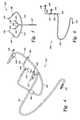
- FIG. 7is an isometric view of the wash water collection system
- FIG. 8is a side view of the wash water collection system, with partial cross-section
- FIG. 9is an isometric view of the trailer and the wash water collection system in association with the aircraft wing and engine;
- FIG. 11is an isometric view of the wash water collection system with a chute extension for an elevated or tail mounted aircraft engine
- FIG. 12is a schematic of the plumbing, piping, and instrumentation of the present invention from the clean water tank to the nozzle manifold, along with the air purge system;
- FIG. 13is a schematic of the plumbing, piping, and instrumentation of the present invention from the wash water collection system to the grey water tank.
- the present inventionrelates to methods and apparatuses for cleaning gas turbine engines. More specifically, the invention relates to methods and apparatuses for cleaning on-wing turbofan engines found on aircraft that includes, among other things, a trailer-mounted, automated low-pressure water delivery system, additive and detergent injection system, nozzle and manifold technology, and active waste water effluent collector system.
- the water wash systemincludes a trailer 10 , a clean water tank 20 , a grey water tank 30 , a wash pump 40 , one or more additive/detergent tanks 50 , a waste water effluent collector 60 , a power generation system 70 , an air compressor/purge system 120 , and a mechanic's point-of-use supply cabinet 150 .
- the trailer 10is a street-legal, enclosed, steel-framed trailer such as those made available from Pace American of Middlebury, Ind., one of the largest manufacturers of enclosed cargo and auto trailers in the world.
- the trailercan range in size from about 4′ wide ⁇ 6′ long to about 8.5′ wide ⁇ 53′ in length, and can be enclosed, partially enclosed, or not enclosed at all.
- the trailercan include factory-installed options and accessories such as air conditioning units, living quarters, awnings, heaters, winches, TVs and sound systems, refrigerators, and other such items.
- the trailer 10is about 20 feet in length and includes a trailer hitch 12 , one or more access or side doors 14 , modular tires 16 , and ramp door 18 .
- the separate componentscan be mounted on separate trailers (or grouped in different configurations and then mounted on different trailers) to allow for user versatility.
- one or more of the componentscan be skid mounted.
- the components of the present inventioncould be mounted inside a tractor trailer rig. The use of a trailer is only necessary when the invention is to be portable. In those applications where portability is not required, a permanent fixed platform may be utilized.
- the clean water tank 20is a square, 316 stainless steel IBC tank capable of holding from about 50 to about 300 gallons of water, preferably 250 gallons. If desired, the tank may be of welded steel construction with its internal surfaces treated, as for example by tinning, to resist corrosion. As is known in the art, there are many available shapes for stainless steel tanks or totes including round, elliptical, conical, cylindrical, cone-topped, truncated, and square. In addition, single and double wall tanks, stackable tanks, and tanks made of different materials (such as aluminum or plastic) are also available and can be used in the present invention. The tank can also be outfitted with emergency vents, pumps, meters, and level indicators. To prevent jostling of liquids, the tank may be baffled.
- the clean water tank 20has a closable filler aperture 23 near its roof whereby a supply of water may be filled into said tank.
- the tankis also provided with one or more drain plugs with sloped bottoms to allow for virtually complete drainage of the transported liquid.
- the clean water tank 20may include banded or immersion heaters or panels (and sufficient tank insulation) to keep the water at proper operating temperatures, preferably from about 150 to about 200 degrees Fahrenheit, most preferably 180 degrees Fahrenheit, or as otherwise required by the appropriate Aircraft Maintenance Manual or turbine engine manufacturer.
- the clean water tank 20is filled with ultra pure water with less than 0.1 parts per million Total Dissolved Solids (TDS) and near 18 MegaOhm resistivity
- the grey water tank 30is also a square, 316 stainless steel IBC tank capable of holding from about 50 to about 300 gallons of water, preferably 250 gallons. It has the same characteristics of the clean water tank, with a closable filler aperture 33 , one or more drain plugs, and baffles to prevent jostling of liquids.
- the grey water tank 30is designed to hold the waste water effluent directed from the effluent collector 60 described below. In fact, the collector 60 may have a sump dewatering pump at its lower trough.
- the wash pump 40is a stainless steel axial piston pump such as those manufactured by Danfoss. This pump is specifically designed for high-purity water applications and is a stainless steel, high efficiency axial piston pump with high recirculating capability.
- the pumpis designed to deliver from about 1 to about 50 gallons per minute of wash water at a pressure of from about 200 to about 725 psi.
- the pump's operating parametersmay be adjusted by a variable-frequency drive attached to the pump's electric motor.
- a variable-frequency driveis an electronic controller that adjusts the speed of the electric motor by modulating the power being delivered.
- Variable-frequency drivesprovide continuous control, matching motor speed to the specific demands of the work being performed.
- Variable-frequency drivesenable pumps to accommodate fluctuating demand, running pumps at lower speeds and drawing less energy while still meeting pumping needs.
- One or more additive/detergent tanks 50can be in fluid communication with the clean water tank. These tanks are preferably 10-50 gallon stainless steel square tanks or totes with large fill openings and output ports for piping.
- the typical detergents, freeze depressants, corrosion inhibitors, and other additives used in this processcan be obtained from manufacturers such as ZOK International Group. Preferably, these chemicals are non-flammable, environmentally friendly, and biodegradable.
- the wash water and engine effluentis collected for treatment with a waste water effluent collector 60 .
- the waste water effluent collector 60is a mobile device that is placed under and behind the aircraft engine 160 . The device captures the contaminated wash water as it exits the engine and separates the waste wash water from the air flow of the engine. The contaminated wash water is collected in a collection base pan 61 and pumped to the grey water tank 30 for later processing.
- a power generation system 70to power the various components discussed above.
- a power sourcewill be provided on the trailer 10 to run, among other things, (a) the heater for the clean water tank, (b) the water pump for the spraying steps, (c) the air purge system, (d) the active fan for the air mist eliminator, (e) the additive injector pumps, (f) the automation panel and related electronics, (g) the effluent collector bilge pump, and (h) the external lighting for night-time or low-light level operations.
- a suitable power generation systemcan include a 480 volt, 3 phase, 60 Hertz diesel engine-driven generator unit from such suppliers as Caterpillar, Hyundai, or Kubota.
- the power generation systemmay be a different voltage, phase and frequency.
- FIG. 3is a side view of the inside of the trailer 10 .
- the trailer 10is about 20 feet in length, 6 feet in width, and includes a trailer hitch 12 , one or more roll-up access or side doors 14 , modular tires 16 , and ramp door 18 .
- trailer 10can include one or more awnings 11 (for protection from sun and rain) and one or more exterior lights 13 , such as 500 watt quartz lights, for night-time or low-level light conditions.
- one or more storage cabinets, compartments, or shelvescan be integrated into the trailer side walls or otherwise provided, for the storage of a variety of equipment or tools used in the present invention.
- this side viewshows one or more automation panels 92 for controlling and monitoring the operation of the system—for example, the trailer can incorporate, among other automation panels and devices, a system control panel, a power generator control panel, a data logging panel, an alarm panel, and an electrical panel; all of which can be stand-alone or incorporated into one CPU-driven device.
- FIGS. 4-6include several views of the manifold and nozzle technology; specifically, FIG. 4 is a perspective view, FIG. 5 is a front view, and FIG. 6 is a side view of the manifold and nozzle technology used in the present invention.
- the piping from the clean water tank 20 and chemical injection tanks 50has connected thereto a length of flexible hose 167 (as shown in FIG. 9 ) for delivering the washing liquid from the trailer 10 to the aircraft for use in washing the blades of the turbine engine.
- the hose 167is releasably connected to a manifold device 100 with stainless steel connectors 105 such as those manufactured by Parker or Swagelok attached to the main manifold inlet pipe 107 .
- the manifold devicemay have a single spray nozzle or a plurality of spray nozzles, each with its own specific spray dispersion pattern, flowrate, and droplet size symmetrically disposed about the air intake of the combustion turbine engine. More specifically, for illustration purposes, the manifold 100 has four arms 101 , 102 , 103 , and 104 , radiating from the main manifold inlet pipe 107 , with each arm having a flow meter 106 and nozzle 108 . Water is sprayed under pressure from these nozzles onto the bypass turbofan blades and into the inlet of the compressor during operation.
- the liquidis dispersed so as to directly impinge upon the pressure and suction side of the bypass blades.
- the pressure for injecting the liquid through the spray nozzles 108is from about 200 to about 725 psi, preferably 700 psi, with a delivery quantity of from about 1 to about 50 gallons per minute of wash water, with the exact flow rate to be determined by the requirements and specifications of the turbine manufacturer or Aircraft Maintenance Manual.
- the nozzle orificesare fixed at sizes ranging from 0.05 mm to 1.3 mm.
- the number of nozzles and radial displacement of each nozzle employedcan be varied to provide the desired volume of liquid for the engine and the wash solution droplet size and spray pattern for the engine component the nozzle is targeting.
- the manifold and nozzle apparatusis releasably connected to the leading edge of the gas turbine engine for dispersing the cleaning or rinsing fluid to the air intake area of the engine and on into the engine's internal air flow path.
- FIGS. 7 and 8are an isometric and side view, with partial cross-section, of the wash water collection system.
- the collector 60includes a commercially available air mist eliminator 62 manufactured by companies such as Koch Industries mounted in front of and ducted to a large capacity outdoor-rated electrically powered fan 64 , a flexible trough 66 mounted on a roller device 68 to channel spillage and engine drain runoff, a collection base pan 61 , and a marine grade bilge pump 63 mounted on the collection base pan with necessary piping and connections to the grey water holding tank 30 in the system trailer 10 . All the components of the collector are mounted on a wheeled frame 65 with pull handle 67 .
- the arrows in FIG. 8show the direction of engine 160 exhaust air flow through the air mist eliminator 62 .
- FIG. 9is an isometric view of the trailer 10 and the wash water collection system 60 in association with the aircraft wing 166 and engine 160 .
- the clean wash wateris delivered from the trailer 10 through connector 15 to hose 167 which is connected to the nozzle manifold 100 at connector 105 .
- the hose 167is a commercial grade, high-pressure hydraulic hose of from about 3 ⁇ 8 inch to about 7 ⁇ 8 inch diameter with a burst strength of about 2000 psi, which can be from about 25 to about 75 feet in length to reach from the trailer 10 to the aircraft engine 160 .
- the wash fluidis expelled through nozzles 108 through the aircraft engine 160 and the resultant effluent is captured by the waste waster collection system 60 .
- the effluent thus capturedis collected and pumped via the marine grade bilge pump 63 through hose 130 to connector 17 on trailer 10 and piped to the grey water holding tank 30 .
- Electrical power to the waste water collection system 60is provided by electrical power cabling 169 extending from power connector 19 on trailer 10 to an electrical receptor box 168 .
- FIG. 10is a side view of the wash water collection system 60 in association with a low mounted aircraft engine 160 .
- the collector 60actively assists the effluent mist by having the fan 64 suction the mist through the mist eliminator 62 where the water droplets are removed by direct impaction to the components of the eliminator 62 .
- the water dropletsare separated from the air flow in the eliminator 62 and drop to a collection base pan 61 mounted on the frame 65 of the collector 60 .
- the now dry air flowcontinues through the fan 64 and is expelled into the atmosphere.
- FIG. 11is an isometric view of the wash water collection system with a chute extension for an elevated or tail mounted aircraft engine.
- the air mist eliminator 62has a diameter just slightly larger than the rear exhaust of the turboengine 160 ; for engines mounted higher than the mist eliminator 62 , a flexible, liquid-impervious connector duct 170 is attached to the mist eliminator 62 and is positioned behind the engine 160 exhaust.
- the flexible duct 170is supported in the air by two or more adjustable support poles 172 removably mounted on the cart frame 65 of the wash water collection system 60 by insertion into one or more stanchions 174 .
- the flexible duct frame 176is slightly larger than the exhaust section of the engine 160 and can be of any geometric shape.
- the poles 172which are terminated on the duct frame 176 with mounted pole brackets 178 , can be height adjusted by various means described in existing art.
- FIG. 12is a schematic of the plumbing, piping, and instrumentation of the present invention associated with the clean water tank 20 and the air purge system, with the components inside the outer rectangle being found inside the trailer 10 .
- the clean water tank 20has a closable filler aperture 23 near its roof whereby a supply of wash water may be filled into the tank.
- the preferred wash wateris ultra pure water with less than 0.1 parts per million Total Dissolved Solids (TDS) and near 18 Megaohm resistivity.
- the use of ultra pure waternecessitates the use of high-purity water pipe, fittings, and valves.
- the ultra pure wateris added to the clean water tank 20 no more than about four hours before the washing process takes place.
- a resistivity meter or conductivity probe 25can be used to monitor the purity of the wash water.
- the clean water tank 20may include banded or immersion heaters or panels 27 (and sufficient tank insulation) to keep the water at proper operating temperatures.
- FIG. 12shows one or more additive/detergent tanks 50 in fluid communication with the clean water tank 20 .
- the additive or detergent or other chemical of interestcan be stored in its own storage tank 50 mounted to the trailer 10 , ready to be mixed with the wash water from the clean tank 20 , by means of a valve or flow meter 52 and chemical injection pump 54 that may be controlled by a variable frequency drive (VFD) and a programmable logic controller.
- VFDvariable frequency drive
- Each additive/detergent tank 50will have its own pump 54 , such as a Webtrol booster pump from Weber Industries.
- the additive or detergent useddepends upon the amount and type of fouling found in the engines, the operating environment of use, and the degree of cleaning required.
- one or more cleaning solutions or detergentscan be added to the wash water to assist in the efficacy and efficiency of the cleaning process.
- Any conventional cleaning solution appropriate for removal of the specific contaminants in the compressor section, typically oils, greases, dust, and entrapped particulatesmay be employed.
- Those skilled in the artare adept at selecting, preparing, and producing such solutions in the desired consistency.
- water alonecan be used only when certain environmental conditions are met.
- freeze depressant additivescan be mixed with the water to lower its freezing point.
- additivescan be injected into the engine to facilitate reducing a rate of formation of particulate matter within the gas turbine engine. More specifically, an anti-static liquid that coats compressor blades within the gas turbine engine to facilitate suppressing static charges from developing within the compressor blades can be employed.
- the clean water tank 20 and additive/detergent tanks 50are in fluid communication with the wash pump 40 .
- the pump 40has a pressure control valve 42 and a variable-frequency drive controller 44 attached to the pump's electric motor to adjust the pump's operating parameters.
- the piping from the pump 40 to the nozzlesincludes a strainer 110 , temperature indicator 112 , and flow meter 52 .
- strainersare placed in-line with process piping to remove large solid contaminants from the flow.
- FIG. 13is a schematic of the plumbing, piping, and instrumentation of the present invention associated with the grey water tank, with the components inside the outer rectangle being found inside the trailer 10 .
- the waste water effluent collector 60which has a marine grade bilge (sump) dewatering pump 62 , is in fluid communication with the gray tank 30 by means of a return hose 130 and associated valves 132 .
- sump pumpsare used in applications where excess water must be pumped away from a particular area. They generally sit in a basin or sump that collects this excess water, hence the name basin sump pump, or simply sump pump.
- the grey water tank 30can be emptied by means of a transfer pump 140 through connector drain 31 .
- the grey water effluentis then available for disposal or further processing in an environmentally safe manner.
- the procedures for washing enginesare specified by the turbine manufacturers or the Aircraft Maintenance Manual.
- the cleaning compositionis applied to the deposits on the turbofan blades and internal engine components by spraying into the engine from about 30 seconds to about 5 minutes, preferably three one minute intervals.
- the enginemay be turned by hand (windmilled) or run using the starter motor alone during application to further promote uniform distribution of the cleaning composition within the engine.
- the cleaning compositionis allowed to soak into the deposits for about 2 to 5 minutes, which allows surface reactions to occur.
- about 3 to 5 such application and soak stepsare cyclically repeated to assure adequate dislodging of the deposits from the engine components.
- the method of application and number of application and soak stepswill vary depending on the engine type, severity of deposit accumulation, and resistance to removal.
- the procedures for on-line and off-line washing of the turbine compressor outlined by the turbine manufacturersare followed.
- Rinsingmay be required to remove both the cleaning composition and loosened deposits from the engine.
- a rinse solutionmay be applied in a similar cyclic application and soak pattern. Using water as the preferred rinsing agent, a 30 second application, while windmilling, followed by soaking for 11 ⁇ 2 minutes and then repeating for about 3 to 8 cycles will provide adequate rinsing. As will be understood by those skilled in the art, any rinsing means which sufficiently removes residual cleaning composition and loosened deposits from the engine may be used.
- the present inventionwill use a feed-back automation system with electronic controllers to adjust the pressure, flow rate, temperature, and duration of the water wash system.
- the wash procedure needed for each engine type and for specific applicationswill be specified in a proprietary computer program running on the system.
- the operatorwill input the necessary information and the system will begin operation according to the required parameters. Of course, manual override and emergency stop procedures will be allowed.
- sampling of the resulting effluent liquidmay be periodically conducted during the cleaning operation for analysis of suspected contaminants.
- the cleaning operationcan be modified.
- the constituent contaminants, the degree of contamination, the selected solvents, the concentration thereof, and the operating temperatureall affect the cleaning time and efficacy.
Landscapes
- Engineering & Computer Science (AREA)
- Mechanical Engineering (AREA)
- Chemical & Material Sciences (AREA)
- General Engineering & Computer Science (AREA)
- Chemical Kinetics & Catalysis (AREA)
- General Chemical & Material Sciences (AREA)
- Combustion & Propulsion (AREA)
- Water Supply & Treatment (AREA)
- Health & Medical Sciences (AREA)
- Public Health (AREA)
- Life Sciences & Earth Sciences (AREA)
- Hydrology & Water Resources (AREA)
- Manufacturing & Machinery (AREA)
- Aviation & Aerospace Engineering (AREA)
- Transportation (AREA)
- Cleaning By Liquid Or Steam (AREA)
- Structures Of Non-Positive Displacement Pumps (AREA)
- Separation Of Particles Using Liquids (AREA)
- Measurement Of Velocity Or Position Using Acoustic Or Ultrasonic Waves (AREA)
- Vehicle Cleaning, Maintenance, Repair, Refitting, And Outriggers (AREA)
- Filtration Of Liquid (AREA)
- Exhaust Gas After Treatment (AREA)
Abstract
Description
Claims (12)
Priority Applications (1)
| Application Number | Priority Date | Filing Date | Title |
|---|---|---|---|
| US12/578,268US9316115B2 (en) | 2004-06-14 | 2009-10-13 | Turboengine wash system |
Applications Claiming Priority (4)
| Application Number | Priority Date | Filing Date | Title |
|---|---|---|---|
| US10/536,002US7297260B2 (en) | 2004-06-14 | 2004-06-14 | System and devices for collecting and treating waste water from engine washing |
| PCT/SE2004/000922WO2005121509A1 (en) | 2004-06-14 | 2004-06-14 | System and devices for collecting and treating waste water from engine washing |
| US11/644,784US8628627B2 (en) | 2004-06-14 | 2006-12-22 | Turboengine water wash system |
| US12/578,268US9316115B2 (en) | 2004-06-14 | 2009-10-13 | Turboengine wash system |
Related Parent Applications (1)
| Application Number | Title | Priority Date | Filing Date |
|---|---|---|---|
| US11/644,784DivisionUS8628627B2 (en) | 2004-06-14 | 2006-12-22 | Turboengine water wash system |
Publications (2)
| Publication Number | Publication Date |
|---|---|
| US20100031977A1 US20100031977A1 (en) | 2010-02-11 |
| US9316115B2true US9316115B2 (en) | 2016-04-19 |
Family
ID=35276280
Family Applications (9)
| Application Number | Title | Priority Date | Filing Date |
|---|---|---|---|
| US10/536,002Expired - LifetimeUS7297260B2 (en) | 2004-06-14 | 2004-06-14 | System and devices for collecting and treating waste water from engine washing |
| US11/629,509Expired - Fee RelatedUS8479754B2 (en) | 2004-06-14 | 2005-06-08 | System for washing an aero gas turbine engine |
| US11/644,784Active2027-05-16US8628627B2 (en) | 2004-06-14 | 2006-12-22 | Turboengine water wash system |
| US11/877,173AbandonedUS20080216873A1 (en) | 2004-06-14 | 2007-10-23 | System and devices for collecting and treating waste water from engine washing |
| US12/578,268Active2025-12-08US9316115B2 (en) | 2004-06-14 | 2009-10-13 | Turboengine wash system |
| US13/887,575Active2027-10-05US10041372B2 (en) | 2004-06-14 | 2013-05-06 | System for washing an aero gas turbine engine |
| US14/096,528Expired - Fee RelatedUS9376932B2 (en) | 2004-06-14 | 2013-12-04 | Turboengine water wash system |
| US14/562,114Expired - Fee RelatedUS9657589B2 (en) | 2004-06-14 | 2014-12-05 | System for washing an aero gas turbine engine |
| US15/152,082Expired - Fee RelatedUS9708928B2 (en) | 2004-06-14 | 2016-05-11 | Turboengine water wash system |
Family Applications Before (4)
| Application Number | Title | Priority Date | Filing Date |
|---|---|---|---|
| US10/536,002Expired - LifetimeUS7297260B2 (en) | 2004-06-14 | 2004-06-14 | System and devices for collecting and treating waste water from engine washing |
| US11/629,509Expired - Fee RelatedUS8479754B2 (en) | 2004-06-14 | 2005-06-08 | System for washing an aero gas turbine engine |
| US11/644,784Active2027-05-16US8628627B2 (en) | 2004-06-14 | 2006-12-22 | Turboengine water wash system |
| US11/877,173AbandonedUS20080216873A1 (en) | 2004-06-14 | 2007-10-23 | System and devices for collecting and treating waste water from engine washing |
Family Applications After (4)
| Application Number | Title | Priority Date | Filing Date |
|---|---|---|---|
| US13/887,575Active2027-10-05US10041372B2 (en) | 2004-06-14 | 2013-05-06 | System for washing an aero gas turbine engine |
| US14/096,528Expired - Fee RelatedUS9376932B2 (en) | 2004-06-14 | 2013-12-04 | Turboengine water wash system |
| US14/562,114Expired - Fee RelatedUS9657589B2 (en) | 2004-06-14 | 2014-12-05 | System for washing an aero gas turbine engine |
| US15/152,082Expired - Fee RelatedUS9708928B2 (en) | 2004-06-14 | 2016-05-11 | Turboengine water wash system |
Country Status (20)
| Country | Link |
|---|---|
| US (9) | US7297260B2 (en) |
| EP (5) | EP2196394B1 (en) |
| JP (5) | JP4249243B2 (en) |
| KR (2) | KR101214321B1 (en) |
| CN (3) | CN1788143B (en) |
| AR (1) | AR049106A1 (en) |
| AT (2) | ATE462870T1 (en) |
| AU (4) | AU2004320619B2 (en) |
| BR (2) | BRPI0418904A (en) |
| CA (3) | CA2506174C (en) |
| DE (5) | DE202004021368U1 (en) |
| DK (3) | DK2196394T3 (en) |
| ES (3) | ES2343409T3 (en) |
| MX (3) | MX344139B (en) |
| MY (1) | MY139149A (en) |
| NO (3) | NO20052431L (en) |
| PL (1) | PL1756399T3 (en) |
| RU (2) | RU2412086C2 (en) |
| TW (2) | TWI419744B (en) |
| WO (2) | WO2005121509A1 (en) |
Cited By (4)
| Publication number | Priority date | Publication date | Assignee | Title |
|---|---|---|---|---|
| US20150354403A1 (en)* | 2014-06-05 | 2015-12-10 | General Electric Company | Off-line wash systems and methods for a gas turbine engine |
| US20160349762A1 (en)* | 2015-05-29 | 2016-12-01 | Pratt & Whitney Canada Corp. | Method and kit for preserving a fuel system of an aircraft engine |
| US10731508B2 (en) | 2017-03-07 | 2020-08-04 | General Electric Company | Method for cleaning components of a turbine engine |
| US20200248583A1 (en)* | 2015-12-11 | 2020-08-06 | General Electric Company | Meta-stable detergent based foam cleaning system and method for gas turbine engines |
Families Citing this family (205)
| Publication number | Priority date | Publication date | Assignee | Title |
|---|---|---|---|---|
| US8246753B2 (en) | 2002-05-13 | 2012-08-21 | Aero Jet Wash Llc | Gaspath cleaning system |
| US8974662B2 (en)* | 2002-10-30 | 2015-03-10 | William J Gannon | Filtration of a pumped hydrocarbon containing liquid |
| CN1788143B (en) | 2004-06-14 | 2011-07-06 | 燃气涡轮效率股份有限公司 | System and apparatus for collecting and treating wastewater from engine cleaning |
| US9790808B2 (en)* | 2005-04-04 | 2017-10-17 | Ecoservices, Llc | Mobile on-wing engine washing and water reclamation system |
| JP4611914B2 (en)* | 2006-02-28 | 2011-01-12 | トーカロ株式会社 | Compressor blade, method for manufacturing the same, and gas turbine for thermal power generation |
| US7597012B2 (en)* | 2006-06-15 | 2009-10-06 | Hitachi Global Storage Technologies Netherlands B.V. | System and method for using a spray/liquid particle count (LPC) to measure particulate contamination |
| GB0614874D0 (en) | 2006-07-27 | 2006-09-06 | Rolls Royce Plc | Aeroengine washing system and method |
| GB0617043D0 (en)* | 2006-08-30 | 2006-10-11 | Rolls Royce Plc | Aeroengine washing system and method |
| US7703272B2 (en)* | 2006-09-11 | 2010-04-27 | Gas Turbine Efficiency Sweden Ab | System and method for augmenting turbine power output |
| US7571735B2 (en)* | 2006-09-29 | 2009-08-11 | Gas Turbine Efficiency Sweden Ab | Nozzle for online and offline washing of gas turbine compressors |
| US8685176B2 (en)* | 2006-10-16 | 2014-04-01 | Ecoservices, Llc | System and method for optimized gas turbine compressor cleaning and performance measurement |
| US7849878B2 (en)* | 2006-10-16 | 2010-12-14 | Gas Turbine Efficiency Sweden Ab | Gas turbine compressor water wash control of drain water purge and sensing of rinse and wash completion |
| US8197609B2 (en)* | 2006-11-28 | 2012-06-12 | Pratt & Whitney Line Maintenance Services, Inc. | Automated detection and control system and method for high pressure water wash application and collection applied to aero compressor washing |
| US8524010B2 (en) | 2007-03-07 | 2013-09-03 | Ecoservices, Llc | Transportable integrated wash unit |
| EP1970133A1 (en)* | 2007-03-16 | 2008-09-17 | Lufthansa Technik AG | Device and method for cleaning the core engine of a turbojet engine |
| EP2052792A3 (en)* | 2007-10-09 | 2011-06-22 | Gas Turbine Efficiency Sweden AB | Drain valve, washing system and sensing of rinse and wash completion |
| US8277647B2 (en)* | 2007-12-19 | 2012-10-02 | United Technologies Corporation | Effluent collection unit for engine washing |
| US8069582B2 (en)* | 2007-12-27 | 2011-12-06 | Daewoo Electronics Corporation | Dryer |
| DE102008014607A1 (en) | 2008-03-17 | 2010-02-25 | Lufthansa Technik Ag | Device for collecting washing liquid from a jet engine wash |
| JP4959612B2 (en)* | 2008-03-18 | 2012-06-27 | 株式会社日立製作所 | Intake air cooling system for gas turbine |
| DE102008021746A1 (en) | 2008-04-30 | 2009-11-19 | Lufthansa Technik Ag | Method and device for cleaning a jet engine |
| US7445677B1 (en) | 2008-05-21 | 2008-11-04 | Gas Turbine Efficiency Sweden Ab | Method and apparatus for washing objects |
| US20090288691A1 (en)* | 2008-05-23 | 2009-11-26 | Hunt Gene C | Solar panel cleaning system |
| DE112009001811T5 (en)* | 2008-07-25 | 2011-06-09 | United Technologies Corporation, East Hartford | Method for identifying CO2 reduction and obtaining carbon credits |
| DE102008047493B4 (en)* | 2008-09-17 | 2016-09-22 | MTU Aero Engines AG | Method for cleaning an engine |
| US20100102835A1 (en)* | 2008-10-27 | 2010-04-29 | General Electric Company | Method and system for detecting a corrosive deposit in a compressor |
| US20110083705A1 (en)* | 2008-11-06 | 2011-04-14 | Stone Roy L | Engine wash system |
| EP2344729A2 (en)* | 2008-11-06 | 2011-07-20 | General Electric Company | Gas turbine engine wash system and method |
| US8245952B2 (en)* | 2009-02-20 | 2012-08-21 | Pratt & Whitney Canada Corp. | Compressor wash nozzle integrated in an inlet case strut |
| US9080460B2 (en)* | 2009-03-30 | 2015-07-14 | Ecoservices, Llc | Turbine cleaning system |
| US20100242994A1 (en)* | 2009-03-30 | 2010-09-30 | Gas Turbine Efficiency Sweden Ab | Device and method for collecting waste water from turbine engine washing |
| US9016293B2 (en)* | 2009-08-21 | 2015-04-28 | Gas Turbine Efficiency Sweden Ab | Staged compressor water wash system |
| RU2422656C1 (en)* | 2009-12-24 | 2011-06-27 | Открытое Акционерное Общество "Российские Железные Дороги" | Cleaning method of flow section of turbine of supercharging turbo-compressor of locomotive internal combustion engine from scale |
| US20110186096A1 (en) | 2010-02-02 | 2011-08-04 | Gas Turbine Efficiency Sweden Ab | Aircraft maintenance unit |
| US9399946B2 (en)* | 2010-05-28 | 2016-07-26 | Donald W. Owens | Hydrogen supplemental system for on-demand hydrogen generation for internal combustion engines |
| US9574492B2 (en) | 2010-03-15 | 2017-02-21 | HNO Green Fuels, Inc. | Portable hydrogen supplemental system and method for lowering particulate matter and other emissions in diesel engines at idle |
| US9138788B2 (en) | 2010-03-23 | 2015-09-22 | Ecoservices, Llc | Device and method having a duct for collecting waste water from turbine engine washing |
| US8206478B2 (en)* | 2010-04-12 | 2012-06-26 | Pratt & Whitney Line Maintenance Services, Inc. | Portable and modular separator/collector device |
| DE102010045869A1 (en) | 2010-08-03 | 2012-02-23 | Mtu Aero Engines Gmbh | Cleaning a turbo machine stage |
| KR101110193B1 (en) | 2011-02-24 | 2012-02-15 | 주식회사 진우에스엠씨 | Mobile Aircraft Engine Washer |
| RU2476713C2 (en)* | 2011-02-25 | 2013-02-27 | Новиков Василий Васильевич | Method of cleaning liquid-propellant rocket engine combustion chamber inner surface |
| DE102011015252A1 (en) | 2011-03-28 | 2012-10-04 | Lufthansa Technik Ag | Cleaning lance and method for cleaning engines |
| US8786848B2 (en)* | 2011-05-05 | 2014-07-22 | Siemens Energy, Inc. | Inspection system for a combustor of a turbine engine |
| FR2975669B1 (en)* | 2011-05-24 | 2013-07-05 | Airbus Operations Sas | METHOD FOR POINTING A PLURALITY OF PREDETERMINAL LOCATIONS WITHIN A STRUCTURE, AND CORRESPONDING SCORING SYSTEM |
| GB201113083D0 (en)* | 2011-07-29 | 2011-09-14 | Formatex Offshore S A L | A method for in-situ cleaning of compressor blades in a gas turbine engine on aircraft and compositions |
| US20130087175A1 (en)* | 2011-10-05 | 2013-04-11 | Petter Investments, Inc. d/b/a Riveer Co | Aircraft Washing System |
| US9206703B2 (en) | 2011-11-01 | 2015-12-08 | Aero Jet Wash Llc | Jet engine cleaning system |
| ITFI20110269A1 (en)* | 2011-12-12 | 2013-06-13 | Nuovo Pignone Spa | "TURNING GEAR FOR GAS TURBINE ARRANGEMENTS" |
| US20130186435A1 (en)* | 2012-01-23 | 2013-07-25 | General Electric Companh | Gas Turbine Compressor Water Wash System |
| CH706151A1 (en)* | 2012-02-29 | 2013-08-30 | Alstom Technology Ltd | A method of operating a gas turbine and gas turbine power plant with feeding sauerstoffreduziertem gas, particularly gas. |
| JP5106695B1 (en)* | 2012-04-02 | 2012-12-26 | 修 小川 | Internal cleaning agent for diesel engine and cleaning system using the same |
| US8998567B2 (en)* | 2012-06-08 | 2015-04-07 | General Electric Company | Method, system and apparatus for enhanced off line compressor and turbine cleaning |
| US9821352B2 (en)* | 2012-06-27 | 2017-11-21 | Ecoservices, Llc | Engine wash apparatus and method |
| US9631511B2 (en)* | 2012-06-27 | 2017-04-25 | Ecoservices, Llc | Engine wash apparatus and method |
| US9138782B2 (en)* | 2012-07-31 | 2015-09-22 | Ecoservices, Llc | Engine wash apparatus and method-collector |
| US9023155B2 (en)* | 2012-07-31 | 2015-05-05 | Ecoservices, Llc | Engine wash apparatus and method—manifold |
| USD706175S1 (en) | 2012-10-17 | 2014-06-03 | II David R. Graham | Secondary containment platform |
| RU2516989C1 (en)* | 2012-10-25 | 2014-05-27 | Федеральное государственное бюджетное образовательное учреждение высшего профессионального образования "Ивановский государственный энергетический университет имени В.И. Ленина" (ИГЭУ) | Method to control valve of periodical blowdown of drum boiler and device for its realisation |
| US10119381B2 (en) | 2012-11-16 | 2018-11-06 | U.S. Well Services, LLC | System for reducing vibrations in a pressure pumping fleet |
| US10020711B2 (en) | 2012-11-16 | 2018-07-10 | U.S. Well Services, LLC | System for fueling electric powered hydraulic fracturing equipment with multiple fuel sources |
| DE102013002636A1 (en) | 2013-02-18 | 2014-08-21 | Jürgen von der Ohe | Device for jet cleaning of unit, particularly of gas turbine jet engines of airplane, has jet nozzle with introduction stop, which limits depth of insertion of jet nozzle into opening, where twist element is arranged to introduction stop |
| DE102013002635A1 (en) | 2013-02-18 | 2014-08-21 | Jürgen von der Ohe | Method for cold jet cleaning of turbine components and e.g. gas turbine engine, of aircraft in airport, involves mixing solid body particles comprising water ice particles into pressure medium of gas and/or water in order to form core jet |
| WO2014124755A1 (en) | 2013-02-18 | 2014-08-21 | Jürgen Von Der Ohe | Method and device for cold jet cleaning |
| US9267393B2 (en)* | 2013-03-04 | 2016-02-23 | General Electric Company | Dry ice cleaning apparatus for gas turbine compressor |
| US9234441B2 (en)* | 2013-03-11 | 2016-01-12 | Pratt & Whitney Canada Corp. | Method of immobilizing low pressure spool and locking tool therefore |
| US9212565B2 (en) | 2013-03-13 | 2015-12-15 | Ecoservices, Llc | Rear mounted wash manifold retention system |
| US9500098B2 (en) | 2013-03-13 | 2016-11-22 | Ecoservices, Llc | Rear mounted wash manifold and process |
| CN105074137B (en)* | 2013-03-15 | 2017-05-10 | 生态服务股份有限公司 | engine washout collector |
| US8951358B2 (en)* | 2013-03-15 | 2015-02-10 | Honeywell International Inc. | Cleaning compositions and methods |
| JP6180145B2 (en)* | 2013-03-26 | 2017-08-16 | 三菱日立パワーシステムズ株式会社 | Intake air cooling system |
| CN103277148A (en)* | 2013-06-05 | 2013-09-04 | 中国南方航空工业(集团)有限公司 | Flushing device and cleaning method of turbine engine |
| US9359959B2 (en)* | 2013-07-31 | 2016-06-07 | General Electric Company | Anti-icing system for a gas turbine |
| US20150075271A1 (en)* | 2013-09-18 | 2015-03-19 | Tire Profiles, Inc | Modular tire tread analyzing station |
| US11643946B2 (en) | 2013-10-02 | 2023-05-09 | Aerocore Technologies Llc | Cleaning method for jet engine |
| CA2963071C (en)* | 2013-10-02 | 2022-09-27 | Aerocore Technologies Llc | Cleaning method for jet engine |
| AU2014374334B2 (en) | 2013-10-10 | 2019-05-16 | Ecoservices, Llc | Radial passage engine wash manifold |
| ITCO20130056A1 (en)* | 2013-11-04 | 2015-05-05 | Nuovo Pignone Srl | INTEGRATED WASHING SYSTEM FOR MOTOR WITH GAS TURBINE. |
| US9452848B2 (en) | 2013-11-07 | 2016-09-27 | Rochem Aviation, Inc. | Method and apparatus for cleaning jet engines |
| US9470105B2 (en)* | 2013-11-21 | 2016-10-18 | General Electric Company | Automated water wash system for a gas turbine engine |
| DE102013224639A1 (en) | 2013-11-29 | 2015-06-03 | Lufthansa Technik Ag | Method and device for cleaning a jet engine |
| DE102013224635A1 (en) | 2013-11-29 | 2015-06-03 | Lufthansa Technik Ag | Method and device for cleaning a jet engine |
| WO2015081998A1 (en)* | 2013-12-04 | 2015-06-11 | Kaercher Futuretech Gmbh | Device system for military and/or humanitarian operations, in particular a mobile decontamination system |
| US20150159506A1 (en)* | 2013-12-06 | 2015-06-11 | General Electric Company | Gas turbine peracetic acid solution inter-rinse |
| US9435260B2 (en) | 2013-12-06 | 2016-09-06 | Bha Altair, Llc | Method and system for testing filter element performance |
| US20150159505A1 (en)* | 2013-12-06 | 2015-06-11 | General Electric Company | Gas turbine organic acid based inter-rinse |
| ITMI20132042A1 (en) | 2013-12-06 | 2015-06-07 | Nuovo Pignone Srl | METHODS FOR WASHING MOTORS WITH GAS TURBINES AND GAS TURBINE ENGINES |
| US9926517B2 (en) | 2013-12-09 | 2018-03-27 | General Electric Company | Cleaning solution and methods of cleaning a turbine engine |
| US9932854B1 (en) | 2013-12-09 | 2018-04-03 | General Electric Company | Methods of cleaning a hot gas flowpath component of a turbine engine |
| FR3014944B1 (en)* | 2013-12-16 | 2016-01-22 | Snecma | DEVICE FOR CLEANING A TURBOMACHINE MODULE |
| US9644350B2 (en)* | 2014-01-23 | 2017-05-09 | Jack Y. Khalifeh | System for recycling grey water |
| US9790834B2 (en) | 2014-03-20 | 2017-10-17 | General Electric Company | Method of monitoring for combustion anomalies in a gas turbomachine and a gas turbomachine including a combustion anomaly detection system |
| DE102014206084A1 (en)* | 2014-03-31 | 2015-10-01 | Lufthansa Technik Ag | Apparatus and method for engine cleaning |
| US20150354462A1 (en)* | 2014-06-05 | 2015-12-10 | General Electric Company | Off-line wash systems and methods for a gas turbine engine |
| US9874108B2 (en) | 2014-07-08 | 2018-01-23 | Rolls-Royce Corporation | Cleaning system for a turbofan gas turbine engine |
| US9657590B2 (en) | 2014-08-04 | 2017-05-23 | Rolls-Royce Corporation | Aircraft engine cleaning system |
| US9821349B2 (en) | 2014-09-10 | 2017-11-21 | Rolls-Royce Corporation | Wands for gas turbine engine cleaning |
| US9644484B2 (en)* | 2014-09-12 | 2017-05-09 | General Electric Company | System and method for providing a film treatment to a surface using inlet bleed heat manifold |
| US20160076456A1 (en)* | 2014-09-12 | 2016-03-17 | General Electric Company | System and method for providing a wash treatment to a surface |
| US9835048B2 (en) | 2014-12-03 | 2017-12-05 | Rolls-Royce Corporation | Turbine engine fleet wash management system |
| US10125782B2 (en) | 2014-12-17 | 2018-11-13 | Envaerospace Inc. | Conditioning method of gas turbine engine components for increasing fuel efficiency |
| US20160186602A1 (en)* | 2014-12-31 | 2016-06-30 | Aerocore Technologies Llc | Nozzle for foam washing of jet engine |
| US9791351B2 (en) | 2015-02-06 | 2017-10-17 | General Electric Company | Gas turbine combustion profile monitoring |
| DE102015209994A1 (en) | 2015-05-29 | 2016-12-15 | Lufthansa Technik Ag | Method and device for cleaning a jet engine |
| CA2907256C (en)* | 2015-10-05 | 2023-08-15 | Katch Kan Holdings Ltd. | Washing apparatus |
| BR102016021259B1 (en) | 2015-10-05 | 2022-06-14 | General Electric Company | METHOD AND SOLUTIONS FOR CLEANING A TURBINE ENGINE AND REAGENT COMPOSITION |
| CN105134301B (en)* | 2015-10-08 | 2017-08-25 | 新兴铸管股份有限公司 | A kind of turbine for installing boiling rotor and stator blade cleaning device additional |
| US10018113B2 (en) | 2015-11-11 | 2018-07-10 | General Electric Company | Ultrasonic cleaning system and method |
| US12078110B2 (en) | 2015-11-20 | 2024-09-03 | Us Well Services, Llc | System for gas compression on electric hydraulic fracturing fleets |
| CN105537173B (en)* | 2015-12-10 | 2017-07-14 | 成都发动机(集团)有限公司 | A kind of fixture for being used to clean the complicated cavity of part |
| US20170204739A1 (en) | 2016-01-20 | 2017-07-20 | General Electric Company | System and Method for Cleaning a Gas Turbine Engine and Related Wash Stand |
| US20170239692A1 (en)* | 2016-02-19 | 2017-08-24 | General Electric Company | Auxiliary Cleaning System for Gas Turbine Engines |
| CN105962853B (en)* | 2016-05-17 | 2018-02-27 | 庄巍 | Indoor building dust removal clearance integration manipulator |
| BE1024315B1 (en)* | 2016-06-28 | 2018-01-30 | Safran Aero Boosters Sa | Propulsion system for aircraft |
| CN109661505B (en)* | 2016-06-29 | 2021-10-22 | 通用电气公司 | Method for wastewater-based condition assessment |
| WO2018017752A1 (en)* | 2016-07-21 | 2018-01-25 | Siemens Healthcare Diagnostics Inc. | Basin and high speed air solution |
| CN106345752B (en)* | 2016-08-22 | 2018-08-07 | 沧州致胜机器人科技有限公司 | A kind of double four-rotor helicopter photovoltaic laser wiping board systems |
| RU2639938C1 (en)* | 2016-09-12 | 2017-12-25 | Открытое акционерное общество "Концерн Кизлярский электромеханический завод (КЭМЗ)" | Method for washing and preserving gas-air path of aircraft engine and device for its implementation |
| EP3504011B1 (en)* | 2016-09-30 | 2024-10-30 | General Electric Company | Water wash system and method for washing a gas turbine engine |
| CN106283473B (en)* | 2016-09-30 | 2018-09-28 | 何平 | A kind of washing machine people |
| EP3507465A4 (en)* | 2016-10-04 | 2020-05-06 | General Electric Company | Collection system for a gas turbine engine wash assembly |
| KR101893377B1 (en)* | 2016-10-10 | 2018-08-30 | 주식회사 굿에어 | Improved Apparatus for Cleaning Air-Conditioner Embedded in Ceiling |
| US10245686B2 (en) | 2016-11-03 | 2019-04-02 | Envaerospace Inc. | Conditioning method of gas turbine engine components for aerodynamic noise reduction |
| US11313246B2 (en)* | 2016-11-30 | 2022-04-26 | General Electric Company | Gas turbine engine wash system |
| CN106679981B (en)* | 2016-12-07 | 2018-10-26 | 中国民航大学 | A kind of aircraft engine cleans simulated experiment platform in the wing |
| CN106742045B (en)* | 2016-12-07 | 2019-04-12 | 中国民航大学 | A kind of aero-engine cleans spraying system in the wing |
| RU2656801C1 (en)* | 2016-12-12 | 2018-06-06 | Закрытое акционерное общество "Турботект Санкт-Петербург" | External flushing system of gas air-cooling unit |
| US10810805B2 (en)* | 2017-02-24 | 2020-10-20 | Moc Products Company, Inc. | Method for cleaning engine deposits |
| US11174751B2 (en) | 2017-02-27 | 2021-11-16 | General Electric Company | Methods and system for cleaning gas turbine engine |
| CN106944393B (en)* | 2017-03-23 | 2019-07-12 | 华南理工大学 | A kind of high undersea hydrostatic pressures water is removed contamination spray head 3 D locating device |
| US10227891B2 (en)* | 2017-03-29 | 2019-03-12 | General Electric Company | Gas turbine engine wash system |
| US11053813B2 (en) | 2017-04-18 | 2021-07-06 | General Electric Company | Turbine component cleaning system and method having detergent recovery and regeneration |
| US20180313225A1 (en) | 2017-04-26 | 2018-11-01 | General Electric Company | Methods of cleaning a component within a turbine engine |
| CN106926256B (en)* | 2017-05-09 | 2018-05-25 | 国网湖南省电力公司带电作业中心 | A kind of transmission system living water washing, deicing implement and its application process |
| CN107132487A (en)* | 2017-06-22 | 2017-09-05 | 广州中国科学院工业技术研究院 | Secondary cell thermal runaway propagates test system |
| CN107442482B (en)* | 2017-08-01 | 2020-05-26 | 春秋航空技术发展江苏有限公司 | Aero-engine cleaning support and cleaning method of aero-engine |
| CN107499531B (en)* | 2017-08-01 | 2019-06-21 | 春秋航空技术发展江苏有限公司 | A kind of aero-engine is in wing cleaning machine |
| CN107497743B (en)* | 2017-08-07 | 2020-06-05 | 江苏江海润液设备有限公司 | Control method for gas turbine cleaning system |
| SG10201707125YA (en)* | 2017-08-31 | 2019-03-28 | United Technologies Corp | Directional water jet cleaning of engine blades |
| JP6950419B2 (en)* | 2017-09-29 | 2021-10-13 | 栗田工業株式会社 | Fin tube cleaning jig and cleaning method |
| CN107476831A (en)* | 2017-09-30 | 2017-12-15 | 中国航发沈阳发动机研究所 | Aircraft engine support case with cleaning function |
| US11028727B2 (en) | 2017-10-06 | 2021-06-08 | General Electric Company | Foaming nozzle of a cleaning system for turbine engines |
| US10871082B2 (en) | 2018-01-02 | 2020-12-22 | General Electric Company | In situ foam generation within a turbine engine |
| US20190210698A1 (en)* | 2018-01-11 | 2019-07-11 | Paul K. Sunden | Foot sprayer attached to watercraft |
| CN108248842B (en)* | 2018-01-25 | 2021-06-04 | 汕头市创新科技电子有限公司 | High-altitude ultrasonic dust removal cleaning machine system |
| US11371385B2 (en) | 2018-04-19 | 2022-06-28 | General Electric Company | Machine foam cleaning system with integrated sensing |
| DE102018110802B3 (en) | 2018-05-04 | 2019-10-10 | Lufthansa Technik Ag | Device for positioning a washing system for jet engines in the engine intake |
| US10815783B2 (en) | 2018-05-24 | 2020-10-27 | General Electric Company | In situ engine component repair |
| PL3578118T3 (en) | 2018-06-05 | 2022-11-21 | Erbe Elektromedizin Gmbh | Surgical instrument |
| US10935460B2 (en)* | 2018-07-17 | 2021-03-02 | General Electric Company | Ultrasonic tank for a turbomachine |
| DE102018119092A1 (en)* | 2018-08-06 | 2020-02-06 | Lufthansa Technik Ag | Device and method for cleaning the core engine of a jet engine |
| DE102018119094A1 (en)* | 2018-08-06 | 2020-02-06 | Lufthansa Technik Ag | Device, method and arrangement for cleaning the core engine of a jet engine |
| US12005480B1 (en)* | 2018-09-19 | 2024-06-11 | Innovative Surface Prep Rentals, Llc | Environmentally safe ultra-high pressure surface cleaning system |
| WO2020081313A1 (en) | 2018-10-09 | 2020-04-23 | U.S. Well Services, LLC | Electric powered hydraulic fracturing pump system with single electric powered multi-plunger pump fracturing trailers, filtration units, and slide out platform |
| US12194620B2 (en) | 2018-10-15 | 2025-01-14 | Oliver Crisipin Robotics Limited | Selectively flexible extension tool |
| US11707819B2 (en) | 2018-10-15 | 2023-07-25 | General Electric Company | Selectively flexible extension tool |
| RU186515U1 (en)* | 2018-10-22 | 2019-01-22 | Общество с ограниченной ответственностью "Искра-Нефтегаз Компрессор" | RINSING RACK FOR CENTRIFUGAL COMPRESSOR FLOWING WASHING DEVICE |
| US10939849B2 (en)* | 2018-10-31 | 2021-03-09 | Monitored Therapeutics, Inc | Low flow spirometer turbine |
| US10799016B2 (en)* | 2018-11-06 | 2020-10-13 | Thomas DePascale | Auto-adjusting vehicle pressure washer |
| RU2702782C1 (en)* | 2018-11-16 | 2019-10-11 | Публичное акционерное общество "ОДК-Уфимское моторостроительное производственное объединение" (ПАО "ОДК-УМПО") | Gas turbine engine |
| KR102139266B1 (en)* | 2018-11-20 | 2020-07-29 | 두산중공업 주식회사 | Gas turbine |
| CN109513672A (en)* | 2018-11-28 | 2019-03-26 | 江苏中盈玻璃科技有限公司 | A kind of cleaning device of mould for glass bottle |
| EP3667031A1 (en)* | 2018-12-14 | 2020-06-17 | ABB Turbo Systems AG | Gas turbine with a cleaning device having particular injectors |
| US11702955B2 (en) | 2019-01-14 | 2023-07-18 | General Electric Company | Component repair system and method |
| CN110053785A (en)* | 2019-04-18 | 2019-07-26 | 中国民航大学 | A kind of cleaning of aircraft engine fan blade and spray equipment |
| US11728709B2 (en) | 2019-05-13 | 2023-08-15 | U.S. Well Services, LLC | Encoderless vector control for VFD in hydraulic fracturing applications |
| WO2021022048A1 (en) | 2019-08-01 | 2021-02-04 | U.S. Well Services, LLC | High capacity power storage system for electric hydraulic fracturing |
| CN110496238B (en)* | 2019-08-28 | 2020-12-15 | 台州市立医院 | A hospital indoor disinfection and cleaning vehicle |
| US12405187B2 (en) | 2019-10-04 | 2025-09-02 | General Electric Company | Insertion apparatus for use with rotary machines |
| GB201914723D0 (en)* | 2019-10-11 | 2019-11-27 | Rolls Royce Plc | Cleaning system and a method of cleaning |
| US11446596B2 (en)* | 2019-10-15 | 2022-09-20 | Honeywell International Inc. | Self refreshing particle separator |
| US12031501B2 (en) | 2019-11-27 | 2024-07-09 | General Electric Company | Cooling system for an engine assembly |
| CN111012256B (en)* | 2019-12-31 | 2021-12-24 | 北京石头世纪科技股份有限公司 | Robot and obstacle detection method |
| US11752622B2 (en) | 2020-01-23 | 2023-09-12 | General Electric Company | Extension tool having a plurality of links |
| US11692650B2 (en) | 2020-01-23 | 2023-07-04 | General Electric Company | Selectively flexible extension tool |
| US11613003B2 (en) | 2020-01-24 | 2023-03-28 | General Electric Company | Line assembly for an extension tool having a plurality of links |
| US11371437B2 (en) | 2020-03-10 | 2022-06-28 | Oliver Crispin Robotics Limited | Insertion tool |
| DE102020206205A1 (en) | 2020-05-18 | 2021-11-18 | MTU Aero Engines AG | Device and method for cleaning an aircraft engine |
| US12091981B2 (en) | 2020-06-11 | 2024-09-17 | General Electric Company | Insertion tool and method |
| US11555413B2 (en) | 2020-09-22 | 2023-01-17 | General Electric Company | System and method for treating an installed and assembled gas turbine engine |
| US11371425B2 (en) | 2020-09-22 | 2022-06-28 | General Electric Company | System and method for cleaning deposit from a component of an assembled, on-wing gas turbine engine |
| US12208925B2 (en) | 2020-10-29 | 2025-01-28 | General Electric Company | Systems and methods of servicing equipment |
| US11938907B2 (en) | 2020-10-29 | 2024-03-26 | Oliver Crispin Robotics Limited | Systems and methods of servicing equipment |
| US11685051B2 (en) | 2020-10-29 | 2023-06-27 | General Electric Company | Systems and methods of servicing equipment |
| US11935290B2 (en) | 2020-10-29 | 2024-03-19 | Oliver Crispin Robotics Limited | Systems and methods of servicing equipment |
| US11915531B2 (en) | 2020-10-29 | 2024-02-27 | General Electric Company | Systems and methods of servicing equipment |
| US11992952B2 (en)* | 2020-10-29 | 2024-05-28 | General Electric Company | Systems and methods of servicing equipment |
| US12139109B2 (en) | 2020-10-29 | 2024-11-12 | General Electric Company | Systems and methods of servicing equipment |
| US11874653B2 (en) | 2020-10-29 | 2024-01-16 | Oliver Crispin Robotics Limited | Systems and methods of servicing equipment |
| US12416800B2 (en) | 2021-01-08 | 2025-09-16 | General Electric Company | Insertion tool |
| CN112845312A (en)* | 2021-01-08 | 2021-05-28 | 抚州元文科技发展有限公司 | Cleaning machine |
| CN113042456A (en)* | 2021-03-23 | 2021-06-29 | 朱爱群 | Medical instrument cleaning equipment capable of treating wastewater |
| US11654547B2 (en) | 2021-03-31 | 2023-05-23 | General Electric Company | Extension tool |
| CN113233524A (en)* | 2021-04-26 | 2021-08-10 | 乌海市中科生态环境技术中心 | Movable sewage purification equipment |
| JP7484815B2 (en)* | 2021-05-31 | 2024-05-16 | 株式会社デンソー | Electric aircraft control device |
| CN114178232A (en)* | 2021-12-02 | 2022-03-15 | 春秋航空技术发展江苏有限公司 | Waste water collecting device for cleaning liquid of turbine engine |
| CN113895651B (en)* | 2021-12-10 | 2022-02-25 | 中国飞机强度研究所 | Method for cooling and discharging high-temperature tail gas of airplane APU (auxiliary Power Unit) in ultralow-temperature environment in laboratory |
| CN114483666B (en)* | 2021-12-31 | 2023-08-22 | 成都航利装备科技有限公司 | Cleaning method for airflow channel of turbofan engine |
| CN114802806B (en)* | 2022-04-27 | 2025-03-07 | 江西中发天信航空发动机科技有限公司 | An experimental method and device for matching inlet boundary layer flow with aviation turbojet engine inlet |
| CN115156153B (en)* | 2022-07-14 | 2023-08-15 | 苏州新佑诚家居科技有限公司 | A wind-electric field coordinated control spray cleaning device for aeroengine blades and its working method |
| FR3144112A1 (en) | 2022-12-22 | 2024-06-28 | Safran Aircraft Engines | Improved process for washing a gas turbine engine |
| US20250122833A1 (en)* | 2023-10-17 | 2025-04-17 | Ge Infrastructure Technology Llc | Airless sprint & water wash system |
| CN117225797B (en)* | 2023-11-14 | 2024-05-28 | 太仓点石航空动力有限公司 | Cleaning system of aeroengine |
| GB202318387D0 (en)* | 2023-12-01 | 2024-01-17 | Rolls Royce Plc | Method for reducing damge to components of gas turbine engines |
| DE102024107903A1 (en) | 2024-03-20 | 2025-09-25 | Lufthansa Technik Aktiengesellschaft | Device, arrangement and method for cleaning a jet engine |
| CN118577578B (en)* | 2024-08-06 | 2024-10-15 | 哈尔滨工业大学(威海) | Rotating water jet composite underwater laser cleaning and additive repair device and method |
Citations (127)
| Publication number | Priority date | Publication date | Assignee | Title |
|---|---|---|---|---|
| US1834534A (en) | 1929-06-13 | 1931-12-01 | American Air Filter Co | Plate for air filters |
| US1926924A (en) | 1928-04-30 | 1933-09-12 | American Air Filter Co | Sinuous air filter and medium |
| US2760597A (en) | 1953-08-19 | 1956-08-28 | Air Maze Corp | Filter panel with zig-zag corrugations |
| US2804903A (en) | 1956-10-11 | 1957-09-03 | George A Davies | Protective cover for a jet engine |
| US2862222A (en) | 1953-12-15 | 1958-12-02 | Jesse S Cockrell | Motor vehicle laundry |
| US2878892A (en) | 1954-09-22 | 1959-03-24 | Ozonair Engineering Company Lt | Self-cleaning filters |
| US2922173A (en) | 1956-07-03 | 1960-01-26 | Chain Belt Co | Purification and reclamation of liquid used in vehicle washing |
| US3219188A (en) | 1962-03-08 | 1965-11-23 | Hirs Gene | Traveling screen filter |
| US3263341A (en) | 1964-02-28 | 1966-08-02 | Russell B Allen | Car wash system |
| US3335916A (en) | 1964-02-29 | 1967-08-15 | A T Juniper Ltd | Apparatus for use in the washing of compressor blades of gas turbine engines |
| US3384239A (en) | 1965-12-07 | 1968-05-21 | Martin J. Berardi | Purification and recirculation of liquid |
| US3481544A (en) | 1968-02-01 | 1969-12-02 | Otto V Jackson | Mobile cleaning unit |
| US3502215A (en) | 1967-11-27 | 1970-03-24 | Robo Wash Inc | Water reclamation apparatus |
| US3527030A (en) | 1967-09-19 | 1970-09-08 | Ernest C Hungate | Eliminator structure |
| US3533395A (en) | 1968-08-12 | 1970-10-13 | Stanray Corp | Aircraft deicer system and apparatus |
| US3550778A (en) | 1969-04-21 | 1970-12-29 | Gussie Kesselman | Waste water reclamation system |
| US3564820A (en) | 1969-04-02 | 1971-02-23 | Henry O Nelson | Gaseous flow separator |
| US3601832A (en) | 1969-09-10 | 1971-08-31 | Vernon H Cook | Aircraft-washing apparatus |
| US3612075A (en) | 1969-01-14 | 1971-10-12 | Vernon H Cook | Aircraft deicing apparatus |
| US3616623A (en) | 1970-01-19 | 1971-11-02 | Laurance S Reid | Mist eliminator |
| US3623668A (en) | 1968-03-04 | 1971-11-30 | Gen Electric | Wash manifold |
| US3646980A (en) | 1970-06-15 | 1972-03-07 | Peterson Products Of San Mateo | Jet engine cowl cover |
| US3766719A (en) | 1971-11-26 | 1973-10-23 | United Aircraft Corp | Particle and moisture separator for engine inlet |
| US3774625A (en) | 1972-02-09 | 1973-11-27 | Ultra Dynamics Corp | Carwash water reclaim system |
| US3835498A (en) | 1972-07-14 | 1974-09-17 | L Arato | Craft washing plant |
| US3911938A (en) | 1973-11-28 | 1975-10-14 | Allen Group | Fully automatic vehicle wash water reclaim system |
| US3923658A (en) | 1973-12-12 | 1975-12-02 | Burdon Eng Ltd E B | Vehicle washing plant |
| US3938972A (en) | 1972-09-08 | 1976-02-17 | Mitsui Shipbuilding And Engineering Co., Ltd. | Impingement separator for gas-liquid mixtures |
| US4029114A (en) | 1976-04-26 | 1977-06-14 | The Allen Group Inc. | Back filter automatic vehicle wash water reclaim system |
| DE2701823A1 (en) | 1976-01-29 | 1977-08-04 | Laszlo Arato | Programmed washing unit for aircraft - .HAS SPRAY NOZZLES MOUNTED ON VEHICLE WITH POSITIONS CONTROLLED DEPENDENT ON LASER SENSORS |
| US4059123A (en) | 1976-10-18 | 1977-11-22 | Avco Corporation | Cleaning and preservation unit for turbine engine |
| US4065322A (en) | 1976-02-23 | 1977-12-27 | General Electric Company | Contamination removal method |
| US4158449A (en) | 1976-12-07 | 1979-06-19 | Pall Corporation | Inlet air cleaner assembly for turbine engines |
| US4168232A (en) | 1977-12-08 | 1979-09-18 | Allen Mark K | Method and apparatus for recycling water in a car wash |
| US4191348A (en) | 1977-11-10 | 1980-03-04 | Holwerda-Huizenga Co. | Deicing system |
| US4196020A (en) | 1978-11-15 | 1980-04-01 | Avco Corporation | Removable wash spray apparatus for gas turbine engine |
| US4225188A (en) | 1978-10-12 | 1980-09-30 | Dresser Industries, Inc. | Apparatus for removing and collecting moisture from a moisture-laden air flow |
| US4234323A (en) | 1978-09-29 | 1980-11-18 | United Technologies Corporation | Collector for water separator |
| GB2074048A (en) | 1980-02-29 | 1981-10-28 | Secr Defence | Spray cleaning apparatus |
| US4300918A (en) | 1978-05-08 | 1981-11-17 | Parmatic Filter Corporation | Method for removing moisture particles |
| US4378755A (en) | 1977-01-12 | 1983-04-05 | Magnusson Ulla M | De-icing and cleaning system for aircrafts |
| US4439241A (en)* | 1982-03-01 | 1984-03-27 | United Technologies Corporation | Cleaning process for internal passages of superalloy airfoils |
| US4462192A (en) | 1982-06-01 | 1984-07-31 | American Standard, Inc. | Seal assembly |
| US4530707A (en) | 1978-11-22 | 1985-07-23 | Ovard John C | Apparatus for removing droplets entrained in a gas stream |
| US4543108A (en) | 1983-08-24 | 1985-09-24 | Dieter Wurz | Mist eliminator for eliminating droplets from a gaseous flow |
| US4557740A (en) | 1984-09-10 | 1985-12-10 | Allis-Chalmers Corporation | Weather louver |
| US4652368A (en) | 1984-08-29 | 1987-03-24 | N/S Corporation | Water filtration system |
| US4684379A (en) | 1985-11-07 | 1987-08-04 | Thermo Kinetics Industries, Inc. | Air cleaner assembly |
| US4713120A (en) | 1986-02-13 | 1987-12-15 | United Technologies Corporation | Method for cleaning a gas turbine engine |
| EP0262097A2 (en) | 1986-09-05 | 1988-03-30 | CECCATO S.p.A. | Automatic washing system particularly for aircraft and related parts |
| USH535H (en) | 1987-10-21 | 1988-10-04 | The United States Of America As Represented By The Secretary Of The Air Force | Compact device for continuous removal of water from an airstream-cascade screen |
| US4802901A (en) | 1986-08-14 | 1989-02-07 | Dieter Wurz | Liquid separator |
| US4834912A (en) | 1986-02-13 | 1989-05-30 | United Technologies Corporation | Composition for cleaning a gas turbine engine |
| US4975101A (en) | 1988-06-23 | 1990-12-04 | Shell International Research Maatschappij B.V. | Device for separating liquid droplets from a gas stream |
| JPH03501360A (en) | 1988-07-08 | 1991-03-28 | ザ・ダウ・ケミカル・カンパニー | Method for purifying gas turbine inlet air |
| US5011540A (en) | 1986-12-24 | 1991-04-30 | Mcdermott Peter | Method and apparatus for cleaning a gas turbine engine |
| US5018355A (en) | 1989-08-28 | 1991-05-28 | Foster Charles D | Method and apparatus for periodic chemical cleanings of turbines |
| US5090588A (en) | 1990-07-31 | 1992-02-25 | Portable Containment, Inc. | Portable containment for chemicals |
| US5093012A (en) | 1990-09-04 | 1992-03-03 | Dennis Bundy | Water reclamation system and method |
| US5114098A (en) | 1990-05-11 | 1992-05-19 | Texaco Inc. | Aircraft engine protective cover |
| US5137555A (en) | 1988-12-22 | 1992-08-11 | Peerless Manufacturing Company | Frontal drain for a marine mist extractor |
| US5160430A (en) | 1991-09-25 | 1992-11-03 | Brite-O-Matic Manufacturing, Inc. | Car wash system using reverse osmosis concentrate for initial rinsing and permeate for final rinsing |
| US5193976A (en) | 1990-02-14 | 1993-03-16 | Turbotect Ag | Injection device for the on-line wet cleaning of compressors |
| US5268011A (en) | 1991-06-11 | 1993-12-07 | Dieter Wurz | Mist eliminator |
| US5269823A (en) | 1992-04-29 | 1993-12-14 | Dieter Wurz | Mist eliminator |
| US5273395A (en) | 1986-12-24 | 1993-12-28 | Rochem Technical Services Holding Ag | Apparatus for cleaning a gas turbine engine |
| US5318254A (en) | 1991-06-28 | 1994-06-07 | Conceptual Solutions, Inc. | Aircraft maintenance robot |
| US5330579A (en) | 1990-02-26 | 1994-07-19 | Eze Products, Inc. | Apparatus and method for spent solvent collection |
| US5354014A (en) | 1993-04-27 | 1994-10-11 | Schwing America, Inc. | System for de-icing airplanes |
| EP0628477A1 (en) | 1993-06-11 | 1994-12-14 | Spar Aerospace Limited | Robot arm and method of its use |
| US5374352A (en) | 1993-04-02 | 1994-12-20 | Pattee; Harley J. | Universal recycled wash water system |
| DE9420362U1 (en) | 1994-12-20 | 1995-03-30 | Hanrath, Rita, 52525 Heinsberg | Detergent catcher for compressor cleaning of aircraft engines |
| US5458299A (en) | 1993-11-17 | 1995-10-17 | Collins; Kenneth | Aircraft deicing apparatus |
| US5462655A (en) | 1993-09-20 | 1995-10-31 | Ladd; Michael | Vehicle containment mat with vacuum recovery and recycle means |
| US5464459A (en) | 1994-06-06 | 1995-11-07 | Koch Engineering Company, Inc. | Chevron type mist eliminator and system |
| US5498329A (en) | 1994-09-12 | 1996-03-12 | Interclean Equipment, Inc. | Vehicle wash apparatus using reclaimed water |
| US5507306A (en) | 1993-12-23 | 1996-04-16 | Howmet Corporation | Cleaning apparatus and method for cleaning internal airfoil cooling passages |
| US5556535A (en) | 1993-11-03 | 1996-09-17 | Micro Tec B.V. | Filtration system for recycling water used in a car wash |
| WO1996040453A1 (en) | 1995-06-07 | 1996-12-19 | Gas Turbine Efficiency Ab | A method of washing objects, such as turbine compressors |
| US5669982A (en) | 1992-07-06 | 1997-09-23 | Latimer; Douglas | Method for collecting wash water or other fluids applied to articles |
| US5725611A (en) | 1994-04-19 | 1998-03-10 | Betzdearborn Inc. | Methods for reducing fouling deposit formation in jet engines |
| US5899217A (en) | 1998-02-10 | 1999-05-04 | Testman, Jr.; Frank L. | Engine wash recovery system |
| JPH11137938A (en) | 1997-11-07 | 1999-05-25 | Kyushu Electric Power Co Inc | Performance deterioration preventing device for gas turbine |
| US5972062A (en) | 1994-12-10 | 1999-10-26 | Zimmermann; Max | Device for separating liquid droplets from a gaseous flow and/or for material and heat exchange |
| US6017377A (en) | 1997-02-03 | 2000-01-25 | Brown; Keith R | Spray paint booth filter |
| US6021792A (en) | 1997-09-11 | 2000-02-08 | Petter; Matthew J. | Modular cleaning facility |
| JP2000136702A (en) | 1998-11-04 | 2000-05-16 | Atox Co Ltd | Turbine rotor automatic blast device |
| US6073637A (en)* | 1998-01-30 | 2000-06-13 | Speciality Chemical Holdings Limited | Cleaning method and apparatus |
| JP2000161081A (en) | 1998-11-25 | 2000-06-13 | Toshiba Corp | Intake device for thermal power plant |
| US6080225A (en) | 1995-06-19 | 2000-06-27 | Foerster; Malte E. C. | Process and device for separating liquid drops from a gas stream |
| US6155277A (en) | 1999-03-30 | 2000-12-05 | Ocean Construction Supplies Limited | On-site concrete truck wash-out apparatus |
| US6310022B1 (en) | 1999-11-30 | 2001-10-30 | Biogenesis Enterprises, Inc. | Chemical cleaning solution for gas turbine blades |
| US20010039794A1 (en)* | 1998-07-24 | 2001-11-15 | Rocklin Mark Stephen | Methods for operating gas turbine engines |
| US20020001255A1 (en) | 2000-04-05 | 2002-01-03 | Flood Jeffrey D. | Portable concrete plant |
| KR100331311B1 (en) | 1998-05-13 | 2002-05-09 | 윤종용 | Apparatus for cleaning carrier for liquid printer |
| EP1205640A2 (en) | 2000-11-01 | 2002-05-15 | General Electric Company | Combined system for cooling by water injection and washing of a gas turbine compressor |
| US6394108B1 (en) | 1999-06-29 | 2002-05-28 | John Jeffrey Butler | Inside out gas turbine cleaning method |
| US6402885B2 (en) | 1996-01-24 | 2002-06-11 | Applied Materials, Inc. | Magnetically enhanced inductively coupled plasma reactor with magnetically confined plasma |
| US20020088480A1 (en) | 2001-01-05 | 2002-07-11 | General Electric Company | Misted air cleaning system and related method |
| US20020092423A1 (en) | 2000-09-05 | 2002-07-18 | Gillingham Gary R. | Methods for filtering air for a gas turbine system |
| US6470668B2 (en) | 1998-07-24 | 2002-10-29 | General Electric Company | Methods and apparatus for water injection in a turbine engine |
| US6478033B1 (en) | 2000-05-26 | 2002-11-12 | Hydrochem Industrial Services, Inc. | Methods for foam cleaning combustion turbines |
| US6491048B1 (en) | 2000-05-26 | 2002-12-10 | Hydrochem Industrial Services, Inc. | Manifold for use in cleaning combustion turbines |
| US6503334B2 (en) | 2001-03-14 | 2003-01-07 | Hydrochem Industrial Services, Inc. | Forced mist cleaning of combustion turbines |
| US6565758B1 (en) | 2000-03-21 | 2003-05-20 | The Centech Group, Inc. | Systems and methods for dispensing, collecting and processing wash fluid |
| US6630198B2 (en) | 2001-01-19 | 2003-10-07 | General Electric Co. | Methods and apparatus for washing gas turbine engines |
| US20030209256A1 (en) | 2002-05-13 | 2003-11-13 | Shahin Tadayon | Jet wet suit cover system for gaspath cleaning |
| US6675437B1 (en) | 1999-12-15 | 2004-01-13 | Shawn L. York | Portable high-temperature, high-pressure washing plant |
| WO2004055334A1 (en) | 2002-12-13 | 2004-07-01 | Gas Turbine Efficiency Ab | A method for cleaning a stationary gas turbine unit during operation |
| WO2005028119A1 (en) | 2003-09-25 | 2005-03-31 | Gas Turbine Efficiency Ab | Nozzle and method for washing gas turbine compressors |
| US6883527B2 (en) | 2002-07-24 | 2005-04-26 | General Electric Company | Method for robotically cleaning compressor blading of a turbine |
| US6932093B2 (en) | 2003-02-24 | 2005-08-23 | General Electric Company | Methods and apparatus for washing gas turbine engine combustors |
| WO2005077554A1 (en)* | 2004-02-16 | 2005-08-25 | Gas Turbine Efficiency Ab | Method and apparatus for cleaning a turbofan gas turbine engine |
| US20050199271A1 (en) | 2004-03-12 | 2005-09-15 | John Watt | Mobile flushing unit and process |
| US6964699B1 (en) | 2002-06-05 | 2005-11-15 | The United States Of America As Represented By The Secretary Of The Navy | Rocket motor exhaust scrubber |
| CA2506174A1 (en)* | 2004-06-14 | 2005-12-14 | Gas Turbine Efficiency Ab | System and devices for collecting and treating waste water from engine washing |
| US20060060233A1 (en) | 2004-09-17 | 2006-03-23 | Ness Lakdawala | Method and a washing system for washing turbines |
| US20060060218A1 (en) | 2004-09-17 | 2006-03-23 | Ness Lakdawala | Method and a washing system for washing |
| US7018965B2 (en) | 2003-09-03 | 2006-03-28 | General Electric Company | Aqueous compositions for cleaning gas turbine compressor blades |
| US7065955B2 (en) | 2003-06-18 | 2006-06-27 | General Electric Company | Methods and apparatus for injecting cleaning fluids into combustors |
| US20060219269A1 (en)* | 2005-04-04 | 2006-10-05 | United Technologies Corporation | Mobile on-wing engine washing and water reclamation system |
| US7150431B2 (en) | 2004-01-14 | 2006-12-19 | Mjd Innovations, L.L.C. | Electrical generator fluid-flow-coolant filtration |
| US20070048127A1 (en) | 2005-08-29 | 2007-03-01 | United Technologies Corporation | Access port for dirt removal for gas turbine engine |
| US7185663B2 (en) | 2002-07-24 | 2007-03-06 | Koch Kenneth W | Methods and compositions for on-line gas turbine cleaning |
| US20070059159A1 (en) | 2005-09-13 | 2007-03-15 | Gas Turbine Efficiency Ab | System and method for augmenting power output from a gas turbine engine |
| US20080178909A1 (en) | 2006-11-28 | 2008-07-31 | Alvestig Per G | Automated detection and control system and method for high pressure water wash application and collection applied to aero compressor washing |
| US20090050183A1 (en) | 2007-08-22 | 2009-02-26 | Rice Robert M | Integrated wash unit for a turbine engine |
Family Cites Families (89)
| Publication number | Priority date | Publication date | Assignee | Title |
|---|---|---|---|---|
| DE341262C (en) | ||||
| US11540A (en)* | 1854-08-15 | Improved process for printing long-napped fabrics | ||
| US2735464A (en)* | 1956-02-21 | kerven | ||
| US1890156A (en) | 1929-07-24 | 1932-12-06 | Konig Wenzel | Shower rose |
| US2041826A (en)* | 1933-08-16 | 1936-05-26 | Garnier Fernand | Apparatus for increasing draft in furnaces and for purifying flue gases |
| US2385393A (en)* | 1941-03-13 | 1945-09-25 | Florus E Wilson | Crankcase flusher |
| CH341262A (en)* | 1955-06-14 | 1959-09-30 | Svenska Turbinfab Ab | Device for cleaning compressors |
| US3074822A (en)* | 1960-04-22 | 1963-01-22 | Dudley Develbiss C | Method for cleaning gas turbines |
| US3081953A (en)* | 1961-02-17 | 1963-03-19 | Bammann Heinrich | Spray head for high-pressure fluids |
| US3168247A (en)* | 1962-09-24 | 1965-02-02 | Schild Helmuth Fred | Pressure washing devices |
| US3308840A (en)* | 1964-07-28 | 1967-03-14 | Archie L Kelley | Engine oil pan and cleaning attachment |
| US3439372A (en)* | 1967-07-10 | 1969-04-22 | Rucker Co | Airplane washing device |
| US3630777A (en)* | 1968-09-24 | 1971-12-28 | Kanegafuchi Spinning Co Ltd | An improved method of cleaning equipment for supplying liquid |
| US3572030A (en) | 1968-12-26 | 1971-03-23 | James D Cuff | Rotary engine assembly |
| US3897263A (en)* | 1973-11-02 | 1975-07-29 | Oliver Thurston Davis | Apparatus for washing and disinfecting trailer or van interiors |
| US3940608A (en)* | 1974-02-04 | 1976-02-24 | Mechanical Technology Incorporated | Fiber optic displacement measuring apparatus |
| JPS54111097A (en)* | 1978-02-21 | 1979-08-31 | Toshiba Corp | Reactore core spray device |
| DE2813236A1 (en)* | 1978-03-28 | 1979-10-11 | Rittershaus & Blecher Gmbh | FILTER PRESS WITH A SPRAY DEVICE |
| GB2040092B (en)* | 1978-11-20 | 1983-01-06 | Reino Int Corp | Automatic alarm system for car backing |
| US4241744A (en)* | 1979-07-02 | 1980-12-30 | Jordan Nathaniel Sr | Cleaning system for tanks |
| US4546459A (en)* | 1982-12-02 | 1985-10-08 | Magnavox Government And Industrial Electronics Company | Method and apparatus for a phased array transducer |
| US4595419A (en)* | 1982-12-27 | 1986-06-17 | Proto-Power Corporation | Ultrasonic decontamination robot |
| JPS6028848A (en)* | 1983-07-26 | 1985-02-14 | Soichi Yamaguchi | Sprayer for preventing dust in natom method |
| US4511488A (en) | 1983-12-05 | 1985-04-16 | Penetone Corporation | D-Limonene based aqueous cleaning compositions |
| US4642192A (en) | 1984-04-30 | 1987-02-10 | Heskett Don E | Method of treating fluids |
| DE3538539A1 (en)* | 1985-10-30 | 1987-05-07 | Joachim Dipl Ing Meier | Movable device for cleaning roadways in particular |
| US4646875A (en)* | 1985-12-30 | 1987-03-03 | Paxton-Mitchell Company | Articulated boom structure |
| US4877043A (en)* | 1987-03-20 | 1989-10-31 | Maurice Carmichael | Internal combustion engine scrubber |
| JPH0634836Y2 (en)* | 1988-01-11 | 1994-09-14 | 三井造船株式会社 | Coanda fluid ejector |
| US4983224A (en) | 1988-10-28 | 1991-01-08 | Rd Chemical Company | Cleaning compositions and methods for removing soldering flux |
| SU1755965A1 (en) | 1989-08-07 | 1992-08-23 | Киевский Институт Инженеров Гражданской Авиации Им.60-Летия Ссср | Method of washing flow-through section of gas-turbine engine |
| DE4029027C2 (en)* | 1989-09-20 | 1999-08-26 | Putzmeister Ag | Device for water jet processing of surfaces with a jet nozzle and an articulated jet nozzle holder |
| US5060887A (en)* | 1989-12-06 | 1991-10-29 | Kean Charles J | Apparatus for deicing an aircraft |
| US5045217A (en)* | 1990-01-26 | 1991-09-03 | Ronan Charles B | Apparatus for cleaning an oil spill off of a beach |
| US5018544A (en)* | 1990-03-06 | 1991-05-28 | Ohmstede Mechanical Services, Inc. | Apparatus for cleaning heat exchanger tube bundles |
| US5188293A (en)* | 1990-04-25 | 1993-02-23 | P.D.Q. Manufacturing Inc. | Fluid applicating and vehicle washing apparatus |
| DK169166B1 (en) | 1990-05-14 | 1994-09-05 | Roulunds Fabriker As | Mat of a liquid-tight, flexible material |
| US5112516A (en) | 1991-01-11 | 1992-05-12 | William D. Sheldon, III | High temperature flashpoint, stable cleaning composition |
| DE4102797C1 (en)* | 1991-01-31 | 1992-05-27 | Mbb Foerder- Und Hebesysteme Gmbh, 2870 Delmenhorst, De | |
| WO1992014557A1 (en) | 1991-02-13 | 1992-09-03 | Sermatech, Inc. | Method and apparatus for injecting a surfactant-based cleaning fluid into an operating gas turbine |
| RU1776846C (en) | 1991-06-10 | 1992-11-23 | Государственный научно-исследовательский институт гражданской авиации | Method of washing gas-air path in gas-turbine engine |
| US5281354A (en) | 1991-10-24 | 1994-01-25 | Amway Corporation | Liquid cleanser composition |
| US5319893A (en)* | 1992-01-28 | 1994-06-14 | Hockett Wayne B | Recovery system |
| US5310022A (en) | 1992-03-20 | 1994-05-10 | Otis Elevator Company | Mechanical overspeed safety device |
| JPH0658172A (en)* | 1992-08-03 | 1994-03-01 | Kobe Steel Ltd | Gas turbine compressor washing device |
| CN1085176A (en) | 1992-10-05 | 1994-04-13 | 成都东方微电子技术应用研究所 | Ground cleaning and testing vehicle for plane hydraulic system |
| JP2584397B2 (en) | 1992-12-04 | 1997-02-26 | 川崎重工業株式会社 | How to create cleaning data for aircraft cleaning units |
| JP2611108B2 (en) | 1993-01-20 | 1997-05-21 | 川崎重工業株式会社 | Control method of aircraft cleaning device |
| CA2120537A1 (en)* | 1993-04-12 | 1994-10-13 | Thomas B. Stanford, Jr. | Megasonic cleaning system using compressed, condensed gases |
| US5518553A (en)* | 1993-04-27 | 1996-05-21 | Moulder; Jeffrey E. | Storage tank cleaning and stripping apparatus and method |
| US5354384A (en)* | 1993-04-30 | 1994-10-11 | Hughes Aircraft Company | Method for cleaning surface by heating and a stream of snow |
| US5306351A (en) | 1993-05-21 | 1994-04-26 | Anderson William J | Waste oil removal composition and method |
| US5401325A (en) | 1993-07-29 | 1995-03-28 | Drew Chemical Corporation | Process for removing carbon deposits using microemulsion cleaners |
| US5376298A (en) | 1993-07-29 | 1994-12-27 | The Procter & Gamble Company | Hard surface detergent compositions |
| DE4428734A1 (en)* | 1993-08-13 | 1995-02-23 | Fraunhofer Ges Forschung | Method of treating an object, in particular an aeroplane |
| JPH08299930A (en)* | 1995-05-09 | 1996-11-19 | Tokyo Isuzu Jidosha Kk | Underground washing device |
| CA2222896C (en) | 1995-06-02 | 2007-07-31 | Ashland Inc. | Stable microemulsion cleaners having low volatile organic content |
| US5597001A (en)* | 1995-06-12 | 1997-01-28 | Royce Industries, L.C. | Portable equipment wash station with retractable flooring system |
| DE19528857C1 (en)* | 1995-08-05 | 1996-10-17 | Wolfgang Hoermann | Slatted-curtain cleaning equipment |
| US5663135A (en) | 1995-08-10 | 1997-09-02 | Corpex Technologies, Inc. | Terpene-based cleaning composition |
| KR19980017193A (en) | 1996-08-30 | 1998-06-05 | 이영리 | The antibacterial water purifier and the metal ion water produced in this water purifier |
| US6134734A (en)* | 1997-01-21 | 2000-10-24 | Marrero; Lou | Aircraft maintenance apparatus and method of maintaining aircraft |
| US6120614A (en)* | 1997-11-14 | 2000-09-19 | Ez Environmental Solutions Corporation | Method and apparatus for pressure washing |
| GB2333695B (en)* | 1998-02-03 | 2001-10-24 | Dennis Roy Yarnold | Cleaning |
| US6062486A (en)* | 1998-07-20 | 2000-05-16 | Hill; Frank | High volume and low pressure water cleaning system |
| US6263889B1 (en)* | 1998-11-02 | 2001-07-24 | Robert A. Flynn | Engine lubrication cleaning system |
| US6820430B1 (en)* | 1999-07-12 | 2004-11-23 | Bruce A. Tassone | Method and apparatus for providing evaporative cooling and power augmentation in gas turbines |
| US6250588B1 (en)* | 1999-07-27 | 2001-06-26 | The United States Of America As Represented By The Secretary Of The Air Force | Forced air de-icing and washing system attached to the distal end of a boom |
| GB2352730B (en) | 1999-07-29 | 2003-04-30 | Ivar Rivenaes Ltd | Metal cleaning composition |
| US6367489B1 (en)* | 2000-03-16 | 2002-04-09 | Soichiro Yamamoto | Brake washer |
| US6964669B1 (en) | 2000-04-12 | 2005-11-15 | Ams Research Corporation | Linear delivery system for deployment of a detachable balloon at a target site in vivo |
| CA2314542A1 (en)* | 2000-07-05 | 2002-01-05 | Christian Mathieu | Mobile washing and wastewater recovery unit |
| US6675548B2 (en)* | 2000-08-31 | 2004-01-13 | Dyk Incorporated | Method and apparatus for texturizing tank walls |
| GB2392918A (en) | 2001-01-11 | 2004-03-17 | Pro Power Technologies Ltd | Internal combustion engine cleaning compositions |
| US6655396B2 (en)* | 2001-02-23 | 2003-12-02 | Art Krenzel | Closed loop pressure washer system with hydro-dynamic continuous flush washing assembly |
| US20020179123A1 (en)* | 2001-05-31 | 2002-12-05 | Charles Toward | Fluidized cleaning and scarification apparatus and method |
| CA2356066A1 (en)* | 2001-08-28 | 2003-02-28 | John M. Goston | Arrangements for the de-icing and anti-icing of aircraft |
| US7521083B2 (en)* | 2001-12-06 | 2009-04-21 | Pp Energy Aps | Method and apparatus for treatment of a rotor blade on a windmill |
| FR2837123B1 (en)* | 2002-03-15 | 2005-03-11 | Aero Strip | METHOD FOR REMOVING SURFACES OF METAL OR COMPOSITE MATERIAL COATED WITH A COATING AND SYSTEM FOR IMPLEMENTING THE PROCESS FOR REMOVING TRANSPORT MACHINES |
| JP3846629B2 (en)* | 2002-07-19 | 2006-11-15 | 株式会社日立プラントテクノロジー | Vehicle underfloor cleaning device |
| DE10256193A1 (en)* | 2002-12-02 | 2004-06-09 | Alstom Technology Ltd | Method for controlling the liquid injection into an inflow channel of an engine or machine |
| SE524657C2 (en) | 2003-01-10 | 2004-09-14 | Bengt-Olov Eriksson | Blokeringsanordning |
| CN2597335Y (en) | 2003-01-17 | 2004-01-07 | 深圳市达航科技有限公司 | Filter for aircraft clear water car |
| US8076271B2 (en) | 2004-06-09 | 2011-12-13 | Halliburton Energy Services, Inc. | Aqueous tackifier and methods of controlling particulates |
| GB2405639A (en) | 2003-09-08 | 2005-03-09 | R Mc Power Recovery Ltd | Metal cleaning compositions |
| US6938405B2 (en)* | 2003-11-13 | 2005-09-06 | General Electric Company | Spray nozzle grid configuration for gas turbine inlet misting system |
| US7934467B2 (en)* | 2004-02-02 | 2011-05-03 | John Stephen Morton | Cost effective automated preparation and coating methodology for large surfaces |
| US7445166B2 (en)* | 2004-05-07 | 2008-11-04 | Jeffrey Marc Williams | Adjustable solid-flow nozzle and method |
| US7445254B2 (en)* | 2005-04-29 | 2008-11-04 | Truth Hardware Corporation | Dual dead bolt latch |
- 2004
- 2004-06-14CNCN2004800012889Apatent/CN1788143B/ennot_activeExpired - Fee Related
- 2004-06-14DKDK10153454.3Tpatent/DK2196394T3/enactive
- 2004-06-14EPEP10153454Apatent/EP2196394B1/ennot_activeExpired - Lifetime
- 2004-06-14ESES04736825Tpatent/ES2343409T3/ennot_activeExpired - Lifetime
- 2004-06-14EPEP04736825Apatent/EP1756399B1/ennot_activeExpired - Lifetime
- 2004-06-14JPJP2007510647Apatent/JP4249243B2/ennot_activeExpired - Fee Related
- 2004-06-14DKDK04736825.3Tpatent/DK1756399T3/enactive
- 2004-06-14CACA2506174Apatent/CA2506174C/ennot_activeExpired - Fee Related
- 2004-06-14PLPL04736825Tpatent/PL1756399T3/enunknown
- 2004-06-14DEDE202004021368Upatent/DE202004021368U1/ennot_activeExpired - Lifetime
- 2004-06-14AUAU2004320619Apatent/AU2004320619B2/ennot_activeCeased
- 2004-06-14USUS10/536,002patent/US7297260B2/ennot_activeExpired - Lifetime
- 2004-06-14WOPCT/SE2004/000922patent/WO2005121509A1/enactiveApplication Filing
- 2004-06-14DEDE602004026362Tpatent/DE602004026362D1/ennot_activeExpired - Lifetime
- 2004-06-14MXMX2010001917Apatent/MX344139B/enunknown
- 2004-06-14MXMXPA06014149Apatent/MXPA06014149A/enactiveIP Right Grant
- 2004-06-14BRBRPI0418904-3Apatent/BRPI0418904A/ennot_activeApplication Discontinuation
- 2004-06-14KRKR1020117009410Apatent/KR101214321B1/ennot_activeExpired - Fee Related
- 2004-06-14ATAT04736825Tpatent/ATE462870T1/enactive
- 2005
- 2005-05-13MYMYPI20052167Apatent/MY139149A/enunknown
- 2005-05-19ARARP050102060Apatent/AR049106A1/enactiveIP Right Grant
- 2005-05-20TWTW099107498Apatent/TWI419744B/ennot_activeIP Right Cessation
- 2005-05-20TWTW094116530Apatent/TWI328474B/ennot_activeIP Right Cessation
- 2005-05-20NONO20052431Apatent/NO20052431L/enunknown
- 2005-06-08RURU2007101311/11Apatent/RU2412086C2/ennot_activeIP Right Cessation
- 2005-06-08DKDK07024134.4Tpatent/DK1897806T3/enactive
- 2005-06-08DEDE202005021369Upatent/DE202005021369U1/ennot_activeExpired - Lifetime
- 2005-06-08JPJP2007515936Apatent/JP4785842B2/ennot_activeExpired - Fee Related
- 2005-06-08BRBRPI0512030-6Apatent/BRPI0512030A/ennot_activeIP Right Cessation
- 2005-06-08ESES05753939Tpatent/ES2297725T3/ennot_activeExpired - Lifetime
- 2005-06-08ESES07024134.4Tpatent/ES2454740T3/ennot_activeExpired - Lifetime
- 2005-06-08AUAU2005251945Apatent/AU2005251945A1/ennot_activeAbandoned
- 2005-06-08DEDE602005003944Tpatent/DE602005003944T2/ennot_activeExpired - Lifetime
- 2005-06-08EPEP10169653Apatent/EP2263809A3/ennot_activeWithdrawn
- 2005-06-08ATAT05753939Tpatent/ATE381482T1/ennot_activeIP Right Cessation
- 2005-06-08KRKR1020077000860Apatent/KR101152056B1/ennot_activeExpired - Fee Related
- 2005-06-08MXMXPA06014006Apatent/MXPA06014006A/enactiveIP Right Grant
- 2005-06-08USUS11/629,509patent/US8479754B2/ennot_activeExpired - Fee Related
- 2005-06-08WOPCT/EP2005/052643patent/WO2005120953A1/enactiveApplication Filing
- 2005-06-08CNCN201010273154.XApatent/CN101972749B/ennot_activeExpired - Fee Related
- 2005-06-08CNCNA2005800195371Apatent/CN1976843A/enactivePending
- 2005-06-08RURU2010136741/11Apatent/RU2554188C2/ennot_activeIP Right Cessation
- 2005-06-08DEDE202005021819Upatent/DE202005021819U1/ennot_activeExpired - Lifetime
- 2005-06-08CACA2570243Apatent/CA2570243C/ennot_activeExpired - Fee Related
- 2005-06-08CACA2714809Apatent/CA2714809C/ennot_activeExpired - Fee Related
- 2005-06-08EPEP07024134.4Apatent/EP1897806B1/ennot_activeExpired - Lifetime
- 2005-06-08EPEP05753939Apatent/EP1755952B1/ennot_activeExpired - Lifetime
- 2006
- 2006-12-22USUS11/644,784patent/US8628627B2/enactiveActive
- 2007
- 2007-01-15NONO20070239Apatent/NO329501B1/ennot_activeIP Right Cessation
- 2007-10-23USUS11/877,173patent/US20080216873A1/ennot_activeAbandoned
- 2009
- 2009-10-13USUS12/578,268patent/US9316115B2/enactiveActive
- 2010
- 2010-07-27NONO20101068Apatent/NO20101068L/enunknown
- 2010-07-30AUAU2010206085Apatent/AU2010206085A1/ennot_activeAbandoned
- 2010-09-14JPJP2010205931Apatent/JP2011007196A/enactivePending
- 2011
- 2011-03-08AUAU2011201020Apatent/AU2011201020B2/ennot_activeCeased
- 2011-05-17JPJP2011110337Apatent/JP5183768B2/ennot_activeExpired - Fee Related
- 2012
- 2012-04-27JPJP2012102912Apatent/JP5280563B2/ennot_activeExpired - Fee Related
- 2013
- 2013-05-06USUS13/887,575patent/US10041372B2/enactiveActive
- 2013-12-04USUS14/096,528patent/US9376932B2/ennot_activeExpired - Fee Related
- 2014
- 2014-12-05USUS14/562,114patent/US9657589B2/ennot_activeExpired - Fee Related
- 2016
- 2016-05-11USUS15/152,082patent/US9708928B2/ennot_activeExpired - Fee Related
Patent Citations (146)
| Publication number | Priority date | Publication date | Assignee | Title |
|---|---|---|---|---|
| US1926924A (en) | 1928-04-30 | 1933-09-12 | American Air Filter Co | Sinuous air filter and medium |
| US1834534A (en) | 1929-06-13 | 1931-12-01 | American Air Filter Co | Plate for air filters |
| US2760597A (en) | 1953-08-19 | 1956-08-28 | Air Maze Corp | Filter panel with zig-zag corrugations |
| US2862222A (en) | 1953-12-15 | 1958-12-02 | Jesse S Cockrell | Motor vehicle laundry |
| US2878892A (en) | 1954-09-22 | 1959-03-24 | Ozonair Engineering Company Lt | Self-cleaning filters |
| US2922173A (en) | 1956-07-03 | 1960-01-26 | Chain Belt Co | Purification and reclamation of liquid used in vehicle washing |
| US2804903A (en) | 1956-10-11 | 1957-09-03 | George A Davies | Protective cover for a jet engine |
| US3219188A (en) | 1962-03-08 | 1965-11-23 | Hirs Gene | Traveling screen filter |
| US3263341A (en) | 1964-02-28 | 1966-08-02 | Russell B Allen | Car wash system |
| US3335916A (en) | 1964-02-29 | 1967-08-15 | A T Juniper Ltd | Apparatus for use in the washing of compressor blades of gas turbine engines |
| US3384239A (en) | 1965-12-07 | 1968-05-21 | Martin J. Berardi | Purification and recirculation of liquid |
| US3527030A (en) | 1967-09-19 | 1970-09-08 | Ernest C Hungate | Eliminator structure |
| US3502215A (en) | 1967-11-27 | 1970-03-24 | Robo Wash Inc | Water reclamation apparatus |
| US3481544A (en) | 1968-02-01 | 1969-12-02 | Otto V Jackson | Mobile cleaning unit |
| US3623668A (en) | 1968-03-04 | 1971-11-30 | Gen Electric | Wash manifold |
| US3533395A (en) | 1968-08-12 | 1970-10-13 | Stanray Corp | Aircraft deicer system and apparatus |
| US3612075A (en) | 1969-01-14 | 1971-10-12 | Vernon H Cook | Aircraft deicing apparatus |
| US3564820A (en) | 1969-04-02 | 1971-02-23 | Henry O Nelson | Gaseous flow separator |
| US3550778A (en) | 1969-04-21 | 1970-12-29 | Gussie Kesselman | Waste water reclamation system |
| US3601832A (en) | 1969-09-10 | 1971-08-31 | Vernon H Cook | Aircraft-washing apparatus |
| US3616623A (en) | 1970-01-19 | 1971-11-02 | Laurance S Reid | Mist eliminator |
| US3646980A (en) | 1970-06-15 | 1972-03-07 | Peterson Products Of San Mateo | Jet engine cowl cover |
| US3766719A (en) | 1971-11-26 | 1973-10-23 | United Aircraft Corp | Particle and moisture separator for engine inlet |
| US3774625A (en) | 1972-02-09 | 1973-11-27 | Ultra Dynamics Corp | Carwash water reclaim system |
| US3835498A (en) | 1972-07-14 | 1974-09-17 | L Arato | Craft washing plant |
| US3938972A (en) | 1972-09-08 | 1976-02-17 | Mitsui Shipbuilding And Engineering Co., Ltd. | Impingement separator for gas-liquid mixtures |
| US3911938A (en) | 1973-11-28 | 1975-10-14 | Allen Group | Fully automatic vehicle wash water reclaim system |
| US3923658A (en) | 1973-12-12 | 1975-12-02 | Burdon Eng Ltd E B | Vehicle washing plant |
| DE2701823A1 (en) | 1976-01-29 | 1977-08-04 | Laszlo Arato | Programmed washing unit for aircraft - .HAS SPRAY NOZZLES MOUNTED ON VEHICLE WITH POSITIONS CONTROLLED DEPENDENT ON LASER SENSORS |
| US4065322A (en) | 1976-02-23 | 1977-12-27 | General Electric Company | Contamination removal method |
| US4029114A (en) | 1976-04-26 | 1977-06-14 | The Allen Group Inc. | Back filter automatic vehicle wash water reclaim system |
| US4059123A (en) | 1976-10-18 | 1977-11-22 | Avco Corporation | Cleaning and preservation unit for turbine engine |
| US4158449A (en) | 1976-12-07 | 1979-06-19 | Pall Corporation | Inlet air cleaner assembly for turbine engines |
| US4378755A (en) | 1977-01-12 | 1983-04-05 | Magnusson Ulla M | De-icing and cleaning system for aircrafts |
| US4191348A (en) | 1977-11-10 | 1980-03-04 | Holwerda-Huizenga Co. | Deicing system |
| US4168232A (en) | 1977-12-08 | 1979-09-18 | Allen Mark K | Method and apparatus for recycling water in a car wash |
| US4300918A (en) | 1978-05-08 | 1981-11-17 | Parmatic Filter Corporation | Method for removing moisture particles |
| US4234323A (en) | 1978-09-29 | 1980-11-18 | United Technologies Corporation | Collector for water separator |
| US4225188A (en) | 1978-10-12 | 1980-09-30 | Dresser Industries, Inc. | Apparatus for removing and collecting moisture from a moisture-laden air flow |
| US4196020A (en) | 1978-11-15 | 1980-04-01 | Avco Corporation | Removable wash spray apparatus for gas turbine engine |
| US4530707A (en) | 1978-11-22 | 1985-07-23 | Ovard John C | Apparatus for removing droplets entrained in a gas stream |
| GB2074048A (en) | 1980-02-29 | 1981-10-28 | Secr Defence | Spray cleaning apparatus |
| US4439241A (en)* | 1982-03-01 | 1984-03-27 | United Technologies Corporation | Cleaning process for internal passages of superalloy airfoils |
| US4462192A (en) | 1982-06-01 | 1984-07-31 | American Standard, Inc. | Seal assembly |
| US4543108A (en) | 1983-08-24 | 1985-09-24 | Dieter Wurz | Mist eliminator for eliminating droplets from a gaseous flow |
| US4652368A (en) | 1984-08-29 | 1987-03-24 | N/S Corporation | Water filtration system |
| US4557740A (en) | 1984-09-10 | 1985-12-10 | Allis-Chalmers Corporation | Weather louver |
| US4684379A (en) | 1985-11-07 | 1987-08-04 | Thermo Kinetics Industries, Inc. | Air cleaner assembly |
| US4713120A (en) | 1986-02-13 | 1987-12-15 | United Technologies Corporation | Method for cleaning a gas turbine engine |
| US4834912A (en) | 1986-02-13 | 1989-05-30 | United Technologies Corporation | Composition for cleaning a gas turbine engine |
| US4802901A (en) | 1986-08-14 | 1989-02-07 | Dieter Wurz | Liquid separator |
| EP0262097A2 (en) | 1986-09-05 | 1988-03-30 | CECCATO S.p.A. | Automatic washing system particularly for aircraft and related parts |
| US5011540A (en) | 1986-12-24 | 1991-04-30 | Mcdermott Peter | Method and apparatus for cleaning a gas turbine engine |
| US5273395A (en) | 1986-12-24 | 1993-12-28 | Rochem Technical Services Holding Ag | Apparatus for cleaning a gas turbine engine |
| USH535H (en) | 1987-10-21 | 1988-10-04 | The United States Of America As Represented By The Secretary Of The Air Force | Compact device for continuous removal of water from an airstream-cascade screen |
| US4975101A (en) | 1988-06-23 | 1990-12-04 | Shell International Research Maatschappij B.V. | Device for separating liquid droplets from a gas stream |
| JPH03501360A (en) | 1988-07-08 | 1991-03-28 | ザ・ダウ・ケミカル・カンパニー | Method for purifying gas turbine inlet air |
| US5137555A (en) | 1988-12-22 | 1992-08-11 | Peerless Manufacturing Company | Frontal drain for a marine mist extractor |
| US5018355A (en) | 1989-08-28 | 1991-05-28 | Foster Charles D | Method and apparatus for periodic chemical cleanings of turbines |
| US5193976A (en) | 1990-02-14 | 1993-03-16 | Turbotect Ag | Injection device for the on-line wet cleaning of compressors |
| US5330579A (en) | 1990-02-26 | 1994-07-19 | Eze Products, Inc. | Apparatus and method for spent solvent collection |
| US5114098A (en) | 1990-05-11 | 1992-05-19 | Texaco Inc. | Aircraft engine protective cover |
| US5090588A (en) | 1990-07-31 | 1992-02-25 | Portable Containment, Inc. | Portable containment for chemicals |
| US5093012A (en) | 1990-09-04 | 1992-03-03 | Dennis Bundy | Water reclamation system and method |
| US5268011A (en) | 1991-06-11 | 1993-12-07 | Dieter Wurz | Mist eliminator |
| US5318254A (en) | 1991-06-28 | 1994-06-07 | Conceptual Solutions, Inc. | Aircraft maintenance robot |
| US5490646A (en) | 1991-06-28 | 1996-02-13 | Conceptual Solutions, Inc. | Aircraft maintenance robot |
| US5160430A (en) | 1991-09-25 | 1992-11-03 | Brite-O-Matic Manufacturing, Inc. | Car wash system using reverse osmosis concentrate for initial rinsing and permeate for final rinsing |
| US5269823A (en) | 1992-04-29 | 1993-12-14 | Dieter Wurz | Mist eliminator |
| US5669982A (en) | 1992-07-06 | 1997-09-23 | Latimer; Douglas | Method for collecting wash water or other fluids applied to articles |
| US5374352A (en) | 1993-04-02 | 1994-12-20 | Pattee; Harley J. | Universal recycled wash water system |
| US5354014A (en) | 1993-04-27 | 1994-10-11 | Schwing America, Inc. | System for de-icing airplanes |
| EP0628477A1 (en) | 1993-06-11 | 1994-12-14 | Spar Aerospace Limited | Robot arm and method of its use |
| US5462655A (en) | 1993-09-20 | 1995-10-31 | Ladd; Michael | Vehicle containment mat with vacuum recovery and recycle means |
| US5556535A (en) | 1993-11-03 | 1996-09-17 | Micro Tec B.V. | Filtration system for recycling water used in a car wash |
| US5458299A (en) | 1993-11-17 | 1995-10-17 | Collins; Kenneth | Aircraft deicing apparatus |
| US5507306A (en) | 1993-12-23 | 1996-04-16 | Howmet Corporation | Cleaning apparatus and method for cleaning internal airfoil cooling passages |
| US5618353A (en) | 1993-12-23 | 1997-04-08 | Howmet Corporation | Cleaning, method for cleaning internal airfoil cooling passages |
| US5725611A (en) | 1994-04-19 | 1998-03-10 | Betzdearborn Inc. | Methods for reducing fouling deposit formation in jet engines |
| US5464459A (en) | 1994-06-06 | 1995-11-07 | Koch Engineering Company, Inc. | Chevron type mist eliminator and system |
| US5498329A (en) | 1994-09-12 | 1996-03-12 | Interclean Equipment, Inc. | Vehicle wash apparatus using reclaimed water |
| US5972062A (en) | 1994-12-10 | 1999-10-26 | Zimmermann; Max | Device for separating liquid droplets from a gaseous flow and/or for material and heat exchange |
| DE9420362U1 (en) | 1994-12-20 | 1995-03-30 | Hanrath, Rita, 52525 Heinsberg | Detergent catcher for compressor cleaning of aircraft engines |
| EP0830220A1 (en) | 1995-06-07 | 1998-03-25 | Gas Turbine Efficiency AB | A method of washing objects, such as turbine compressors |
| US5868860A (en) | 1995-06-07 | 1999-02-09 | Gas Turbine Efficiency Ab | Method of washing objects, such as turbine compressors |
| JPH11507583A (en) | 1995-06-07 | 1999-07-06 | ガス タービン エフィシエンシー アクティエボラーグ | How to clean objects such as turbine compressors |
| WO1996040453A1 (en) | 1995-06-07 | 1996-12-19 | Gas Turbine Efficiency Ab | A method of washing objects, such as turbine compressors |
| US6080225A (en) | 1995-06-19 | 2000-06-27 | Foerster; Malte E. C. | Process and device for separating liquid drops from a gas stream |
| US6402885B2 (en) | 1996-01-24 | 2002-06-11 | Applied Materials, Inc. | Magnetically enhanced inductively coupled plasma reactor with magnetically confined plasma |
| US6017377A (en) | 1997-02-03 | 2000-01-25 | Brown; Keith R | Spray paint booth filter |
| US6021792A (en) | 1997-09-11 | 2000-02-08 | Petter; Matthew J. | Modular cleaning facility |
| US6164298A (en) | 1997-09-11 | 2000-12-26 | Petter; Matthew J. | Modular cleaning facility |
| JPH11137938A (en) | 1997-11-07 | 1999-05-25 | Kyushu Electric Power Co Inc | Performance deterioration preventing device for gas turbine |
| US6073637A (en)* | 1998-01-30 | 2000-06-13 | Speciality Chemical Holdings Limited | Cleaning method and apparatus |
| US5899217A (en) | 1998-02-10 | 1999-05-04 | Testman, Jr.; Frank L. | Engine wash recovery system |
| KR100331311B1 (en) | 1998-05-13 | 2002-05-09 | 윤종용 | Apparatus for cleaning carrier for liquid printer |
| US6470668B2 (en) | 1998-07-24 | 2002-10-29 | General Electric Company | Methods and apparatus for water injection in a turbine engine |
| US20010039794A1 (en)* | 1998-07-24 | 2001-11-15 | Rocklin Mark Stephen | Methods for operating gas turbine engines |
| US6484508B2 (en) | 1998-07-24 | 2002-11-26 | General Electric Company | Methods for operating gas turbine engines |
| JP2000136702A (en) | 1998-11-04 | 2000-05-16 | Atox Co Ltd | Turbine rotor automatic blast device |
| JP2000161081A (en) | 1998-11-25 | 2000-06-13 | Toshiba Corp | Intake device for thermal power plant |
| US6155277A (en) | 1999-03-30 | 2000-12-05 | Ocean Construction Supplies Limited | On-site concrete truck wash-out apparatus |
| US6394108B1 (en) | 1999-06-29 | 2002-05-28 | John Jeffrey Butler | Inside out gas turbine cleaning method |
| US6310022B1 (en) | 1999-11-30 | 2001-10-30 | Biogenesis Enterprises, Inc. | Chemical cleaning solution for gas turbine blades |
| US6675437B1 (en) | 1999-12-15 | 2004-01-13 | Shawn L. York | Portable high-temperature, high-pressure washing plant |
| US6565758B1 (en) | 2000-03-21 | 2003-05-20 | The Centech Group, Inc. | Systems and methods for dispensing, collecting and processing wash fluid |
| US20020001255A1 (en) | 2000-04-05 | 2002-01-03 | Flood Jeffrey D. | Portable concrete plant |
| US6478033B1 (en) | 2000-05-26 | 2002-11-12 | Hydrochem Industrial Services, Inc. | Methods for foam cleaning combustion turbines |
| US6491048B1 (en) | 2000-05-26 | 2002-12-10 | Hydrochem Industrial Services, Inc. | Manifold for use in cleaning combustion turbines |
| US20020092423A1 (en) | 2000-09-05 | 2002-07-18 | Gillingham Gary R. | Methods for filtering air for a gas turbine system |
| US6553768B1 (en)* | 2000-11-01 | 2003-04-29 | General Electric Company | Combined water-wash and wet-compression system for a gas turbine compressor and related method |
| EP1205640A2 (en) | 2000-11-01 | 2002-05-15 | General Electric Company | Combined system for cooling by water injection and washing of a gas turbine compressor |
| US20020088480A1 (en) | 2001-01-05 | 2002-07-11 | General Electric Company | Misted air cleaning system and related method |
| US6630198B2 (en) | 2001-01-19 | 2003-10-07 | General Electric Co. | Methods and apparatus for washing gas turbine engines |
| US6503334B2 (en) | 2001-03-14 | 2003-01-07 | Hydrochem Industrial Services, Inc. | Forced mist cleaning of combustion turbines |
| US20030209256A1 (en) | 2002-05-13 | 2003-11-13 | Shahin Tadayon | Jet wet suit cover system for gaspath cleaning |
| US6964699B1 (en) | 2002-06-05 | 2005-11-15 | The United States Of America As Represented By The Secretary Of The Navy | Rocket motor exhaust scrubber |
| US7185663B2 (en) | 2002-07-24 | 2007-03-06 | Koch Kenneth W | Methods and compositions for on-line gas turbine cleaning |
| US6883527B2 (en) | 2002-07-24 | 2005-04-26 | General Electric Company | Method for robotically cleaning compressor blading of a turbine |
| WO2004055334A1 (en) | 2002-12-13 | 2004-07-01 | Gas Turbine Efficiency Ab | A method for cleaning a stationary gas turbine unit during operation |
| US20060243308A1 (en) | 2002-12-13 | 2006-11-02 | Peter Asplund | Method for cleaning a stationary gas turbine unit during operation |
| US6932093B2 (en) | 2003-02-24 | 2005-08-23 | General Electric Company | Methods and apparatus for washing gas turbine engine combustors |
| US7065955B2 (en) | 2003-06-18 | 2006-06-27 | General Electric Company | Methods and apparatus for injecting cleaning fluids into combustors |
| US7018965B2 (en) | 2003-09-03 | 2006-03-28 | General Electric Company | Aqueous compositions for cleaning gas turbine compressor blades |
| US20070000528A1 (en) | 2003-09-25 | 2007-01-04 | Gas Turbine Efficiency Ab | Nozzle and method for washing gas turbine compressors |
| WO2005028119A1 (en) | 2003-09-25 | 2005-03-31 | Gas Turbine Efficiency Ab | Nozzle and method for washing gas turbine compressors |
| US7150431B2 (en) | 2004-01-14 | 2006-12-19 | Mjd Innovations, L.L.C. | Electrical generator fluid-flow-coolant filtration |
| WO2005077554A1 (en)* | 2004-02-16 | 2005-08-25 | Gas Turbine Efficiency Ab | Method and apparatus for cleaning a turbofan gas turbine engine |
| US20060048796A1 (en) | 2004-02-16 | 2006-03-09 | Peter Asplund | Method and apparatus for cleaning a turbofan gas turbine engine |
| US20050199270A1 (en)* | 2004-03-12 | 2005-09-15 | John Watt | Mobile flushing unit and process |
| US7198052B2 (en) | 2004-03-12 | 2007-04-03 | General Electric Company | Mobile flushing unit and process |
| US20050199271A1 (en) | 2004-03-12 | 2005-09-15 | John Watt | Mobile flushing unit and process |
| US20060081521A1 (en) | 2004-06-14 | 2006-04-20 | Carl-Johan Hjerpe | System and devices for collecting and treating waste water from engine washing |
| US20080040872A1 (en) | 2004-06-14 | 2008-02-21 | Carl-Johan Hjerpe | System for Washing an Aero Gas Turbine Engine |
| CA2506174A1 (en)* | 2004-06-14 | 2005-12-14 | Gas Turbine Efficiency Ab | System and devices for collecting and treating waste water from engine washing |
| WO2005120953A1 (en) | 2004-06-14 | 2005-12-22 | Gas Turbine Efficiency Ab | System for washing an aero gas turbine engine |
| WO2005121509A1 (en) | 2004-06-14 | 2005-12-22 | Gas Turbine Efficiency Ab | System and devices for collecting and treating waste water from engine washing |
| US20080216873A1 (en) | 2004-06-14 | 2008-09-11 | Gas Turbine Efficiency Ab | System and devices for collecting and treating waste water from engine washing |
| US7297260B2 (en) | 2004-06-14 | 2007-11-20 | Gas Turbine Efficiency Ab | System and devices for collecting and treating waste water from engine washing |
| US20060060233A1 (en) | 2004-09-17 | 2006-03-23 | Ness Lakdawala | Method and a washing system for washing turbines |
| US20060060218A1 (en) | 2004-09-17 | 2006-03-23 | Ness Lakdawala | Method and a washing system for washing |
| US20060219269A1 (en)* | 2005-04-04 | 2006-10-05 | United Technologies Corporation | Mobile on-wing engine washing and water reclamation system |
| US20070048127A1 (en) | 2005-08-29 | 2007-03-01 | United Technologies Corporation | Access port for dirt removal for gas turbine engine |
| US20070059159A1 (en) | 2005-09-13 | 2007-03-15 | Gas Turbine Efficiency Ab | System and method for augmenting power output from a gas turbine engine |
| US20080178909A1 (en) | 2006-11-28 | 2008-07-31 | Alvestig Per G | Automated detection and control system and method for high pressure water wash application and collection applied to aero compressor washing |
| US20090050183A1 (en) | 2007-08-22 | 2009-02-26 | Rice Robert M | Integrated wash unit for a turbine engine |
Non-Patent Citations (2)
| Title |
|---|
| "Engine Washing." Aviation Today. Oct. 1, 2006. .* |
| "Engine Washing." Aviation Today. Oct. 1, 2006. <http://www.aviationtoday.com/am/categories/bga/Engine-Washing-5248.html>.* |
Cited By (7)
| Publication number | Priority date | Publication date | Assignee | Title |
|---|---|---|---|---|
| US20150354403A1 (en)* | 2014-06-05 | 2015-12-10 | General Electric Company | Off-line wash systems and methods for a gas turbine engine |
| US20160349762A1 (en)* | 2015-05-29 | 2016-12-01 | Pratt & Whitney Canada Corp. | Method and kit for preserving a fuel system of an aircraft engine |
| US10287909B2 (en)* | 2015-05-29 | 2019-05-14 | Pratt & Whitney Canada Corp. | Method and kit for preserving a fuel system of an aircraft engine |
| US20200248583A1 (en)* | 2015-12-11 | 2020-08-06 | General Electric Company | Meta-stable detergent based foam cleaning system and method for gas turbine engines |
| US11415019B2 (en) | 2015-12-11 | 2022-08-16 | General Electric Company | Meta-stable detergent based foam cleaning system and method for gas turbine engines |
| US11591928B2 (en)* | 2015-12-11 | 2023-02-28 | General Electric Company | Meta-stable detergent based foam cleaning system and method for gas turbine engines |
| US10731508B2 (en) | 2017-03-07 | 2020-08-04 | General Electric Company | Method for cleaning components of a turbine engine |
Also Published As
Similar Documents
| Publication | Publication Date | Title |
|---|---|---|
| US9708928B2 (en) | Turboengine water wash system | |
| US9744566B2 (en) | Device and method having a duct for collecting waste water from turbine engine washing | |
| US9790808B2 (en) | Mobile on-wing engine washing and water reclamation system | |
| KR20130082487A (en) | Device and method for collecting waste water from turbine engine washing | |
| CN102151667B (en) | Method for cleaning engine and collecting waste liquid | |
| CA2763088C (en) | System and devices for collecting and treating waste water from engine washing | |
| AU2012258473B2 (en) | System and devices for collecting and treating waste water from engine washing | |
| HK1092854B (en) | System and devices for collecting and treating waste water from engine washing | |
| HK1159552B (en) | Method of washing an engine and collecting waste liquid |
Legal Events
| Date | Code | Title | Description |
|---|---|---|---|
| AS | Assignment | Owner name:PRATT & WHITNEY LINE MAINTENANCE SERVICES, INC., C Free format text:ASSIGNMENT OF ASSIGNORS INTEREST;ASSIGNORS:GAS TURBINE EFFICIENCY AB;GAS TURBINE EFFICIENCY SWEDEN AS;REEL/FRAME:025859/0110 Effective date:20110111 | |
| AS | Assignment | Owner name:ECOSERVICES, LLC, CONNECTICUT Free format text:ASSIGNMENT OF ASSIGNORS INTEREST;ASSIGNOR:PRATT & WHITNEY LINE MAINTENANCE SERVICES, INC.;REEL/FRAME:030238/0298 Effective date:20130311 | |
| AS | Assignment | Owner name:GAS TURBINE EFFICIENCY SWEDEN AB, SWEDEN Free format text:ASSIGNMENT OF ASSIGNORS INTEREST;ASSIGNOR:SALES, HUBERT E., JR.;REEL/FRAME:037118/0690 Effective date:20090131 | |
| STCF | Information on status: patent grant | Free format text:PATENTED CASE | |
| AS | Assignment | Owner name:PRATT & WHITNEY LINE MAINTENANCE SERVICES, INC., C Free format text:CORRECTIVE ASSIGNMENT TO CORRECT THE THE NAME OF THE 2ND ASSIGNOR PREVIOUSLY RECORDED AT REEL: 025859 FRAME: 0110. ASSIGNOR(S) HEREBY CONFIRMS THE ASSIGNMENT;ASSIGNORS:GAS TURBINE EFFICIENCY AB;GAS TURBINE EFFICIENCY SWEDEN AB;REEL/FRAME:044167/0036 Effective date:20110118 | |
| FEPP | Fee payment procedure | Free format text:ENTITY STATUS SET TO UNDISCOUNTED (ORIGINAL EVENT CODE: BIG.) | |
| MAFP | Maintenance fee payment | Free format text:PAYMENT OF MAINTENANCE FEE, 4TH YEAR, LARGE ENTITY (ORIGINAL EVENT CODE: M1551); ENTITY STATUS OF PATENT OWNER: LARGE ENTITY Year of fee payment:4 | |
| MAFP | Maintenance fee payment | Free format text:PAYMENT OF MAINTENANCE FEE, 8TH YEAR, LARGE ENTITY (ORIGINAL EVENT CODE: M1552); ENTITY STATUS OF PATENT OWNER: LARGE ENTITY Year of fee payment:8 |