US9316053B2 - Methods and systems for drilling boreholes - Google Patents
Methods and systems for drilling boreholesDownload PDFInfo
- Publication number
- US9316053B2 US9316053B2US13/524,623US201213524623AUS9316053B2US 9316053 B2US9316053 B2US 9316053B2US 201213524623 AUS201213524623 AUS 201213524623AUS 9316053 B2US9316053 B2US 9316053B2
- Authority
- US
- United States
- Prior art keywords
- drill
- routine
- borehole
- computer
- phase
- Prior art date
- Legal status (The legal status is an assumption and is not a legal conclusion. Google has not performed a legal analysis and makes no representation as to the accuracy of the status listed.)
- Active, expires
Links
Images


Classifications
- E—FIXED CONSTRUCTIONS
- E21—EARTH OR ROCK DRILLING; MINING
- E21B—EARTH OR ROCK DRILLING; OBTAINING OIL, GAS, WATER, SOLUBLE OR MELTABLE MATERIALS OR A SLURRY OF MINERALS FROM WELLS
- E21B7/00—Special methods or apparatus for drilling
- E—FIXED CONSTRUCTIONS
- E21—EARTH OR ROCK DRILLING; MINING
- E21B—EARTH OR ROCK DRILLING; OBTAINING OIL, GAS, WATER, SOLUBLE OR MELTABLE MATERIALS OR A SLURRY OF MINERALS FROM WELLS
- E21B44/00—Automatic control systems specially adapted for drilling operations, i.e. self-operating systems which function to carry out or modify a drilling operation without intervention of a human operator, e.g. computer-controlled drilling systems; Systems specially adapted for monitoring a plurality of drilling variables or conditions
- E21B44/02—Automatic control of the tool feed
- E21B44/04—Automatic control of the tool feed in response to the torque of the drive ; Measuring drilling torque
Definitions
- This inventionrelates to methods and systems for drilling boreholes in general and more specifically to methods and systems for drilling blastholes of the type commonly used in mining and quarrying operations.
- boreholesare typically filled with an explosive that, when detonated, ruptures or fragments the surrounding rock. Thereafter, the fragmented material can be removed and processed in a manner consistent with the particular operation.
- blastholesWhen used for this purpose, then, such boreholes are commonly referred to as “blastholes,” although the terms may be used interchangeably.
- a number of factors influence the effectiveness of the blastincluding the nature of the geologic structure (i.e., rock), the size and spacing of the blastholes, the burden (i.e., distance to the free face of the geologic structure), the type, amount, and placement of the explosive, as well as the order in which the blastholes are detonated.
- the size, spacing, and depth of the blastholesrepresent the primary means of controlling the degree of rupture or fragmentation of the geologic structure, and considerable effort goes into developing a blasthole specification that will produce the desired result. Because the actual results of the blasting operation are highly correlated with the degree to which the actual blastholes conform to the desired blasthole specification, it is important to ensure that the actual blastholes conform as closely as possible to the desired specification.
- blastholesthat truly conform to the desired specification.
- a typical blasting operationinvolves the formation several tens, if not hundreds, of blastholes, each of which must be drilled in proper location (i.e., to form the desired blasthole pattern) and to the proper depth.
- a relatively high hole compliance ratei.e., the percentage of blastholes that comply with the desired specification
- the large number of blastholes involved in a typical operationmeans that a significant number of blastholes nevertheless may fail to comply with the specification.
- a system for drilling a boreholeincludes a computer-readable medium containing program instructions.
- the program instructionsWhen the program instructions are executed by one or more processors of a computer system operatively associated with a drill rig, the program instructions cause the one or more processors to carry out the steps of: initiating a drilling phase; monitoring a drill parameter during the drilling phase, the monitored drill parameter comprising at least one of drill rotational speed, drill torque or number of drill retractions; determining whether the monitored drill parameter is within a predetermined specification for the monitored drill parameter; choosing a drilling phase defect mitigation routine based on the monitored drill parameter when the monitored drill parameter is outside the predetermined specification; implementing the drilling phase defect mitigation routine; and resuming the drilling phase.
- a computer-readable mediummay include program instructions for drilling a borehole that, when executed by one or more processors of a computer system operatively associated with a drill rig, cause the one or more processors to carry out the steps of: monitoring a drill parameter during a drilling phase and a retraction phase; using the monitored drill parameter to draw a conclusion about a borehole characteristic; choosing a defect mitigation routine based on the borehole characteristic; and implementing the defect mitigation routine.
- FIG. 1is a side view in elevation of a blasthole drill rig embodying the systems and methods of the present invention
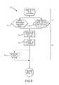
- FIG. 2is a schematic representation of a blasthole drilling system according to one embodiment of the present invention.
- FIG. 3is a flow chart of one embodiment of a method for drilling blastholes
- FIG. 4is a schematic representation of drilling phase mitigation routines
- FIG. 5is a schematic representation of retraction phase mitigation routines
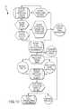
- FIG. 6is a flow chart of a collaring routine
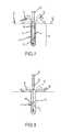
- FIG. 7is a pictorial representation of a borehole during a first phase of the collaring routine
- FIG. 8is a pictorial representation of a borehole during a second phase of the collaring routine
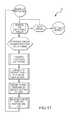
- FIG. 9is a flow chart of an air pressure protection routine
- FIG. 10is a flow chart of a rotary stall protection routine
- FIG. 11is a pictorial representation of a borehole showing moderate and heavy fracture zones
- FIG. 12is a flow chart of an end-of-hole spin-out routine
- FIG. 13is a flow chart of an end-of-hole water control routine
- FIG. 14is a flow chart of an end-of-hole measurement routine
- FIG. 15is a flow chart of a drill bit hang-up protection routine
- FIG. 16is a pictorial representation of a borehole showing a blockage area around the drill.
- FIG. 17is a flow chart of a torque monitoring routine.
- blastholes 14of the type commonly used in mining and quarrying operations.
- the various blastholes 14are then filled with an explosive material (not shown).
- the subsequent detonation of the explosive materialruptures or fragments the geologic structure 15 , which may then be collected and processed in a manner consistent with the intended application (e.g., mining or quarrying, as the case may be).
- the system 10 of the present inventionincreases the quality of boreholes 12 , i.e., the percentage of boreholes 12 that comply with the desired borehole specification.
- the present inventionnot only increases initial hole quality, i.e., immediately after the boreholes 12 are drilled, but also long-term hole quality, i.e., the percentage of boreholes 12 that remain in compliance after they have been formed. That is, boreholes 12 that are formed in accordance with the teachings of the present invention are less subject to cave-ins and other post-drilling events that would otherwise make compliant boreholes 12 non-compliant.
- the present inventionincreases both initial and long-term borehole quality by monitoring one or more drill parameters while the boreholes 12 are being formed or drilled.
- the monitored drill parameter(s)is compared with a predetermined specification for the parameter(s). If the monitored drill parameter is outside the specification, the present invention selects and implements one or more defect mitigation routines to ensure that the borehole 12 is drilled to the desired specification. Significantly, the defect mitigation routine(s) also helps to ensure that the borehole 12 remains compliant even after it has been drilled.
- the system 10uses the monitored drill parameter to draw a conclusion about one or more borehole characteristics. The system then chooses the mitigation routine that will most effectively mitigate or compensate for the particular borehole characteristic. Consequently, the present invention allows for a significant increase in the number of boreholes 12 that are compliant with the particular borehole specification, both on an initial and long-term basis.
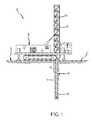
- the system 10may comprise a drill rig 16 having a mast or derrick 18 configured to support a drill string 20 having a drill bit 32 provided on the end thereof.
- Drill rig 16may also be provided with various systems for operating the drill string 20 to form boreholes 12 (e.g., blastholes 14 ).
- drill rig 16may also comprise a drill motor system 22 , a drill hoist system 24 , an air injection system 26 , and a water injection system 28 , as best seen in FIG. 2 .
- the system 10 of the present inventionmay also comprise a control system 30 that is operatively associated with the drill rig 16 , as well as the various systems thereof, e.g., motor system 22 , hoist system 24 , air injection system 26 , and water injection system 28 .
- control system 30monitors various drill parameters generated or produced by the various drill systems and controls them as necessary to form the blasthole 14 . In doing so, control system 30 may also implement the various hole defect mitigation routines 40 and 42 ( FIGS. 4 and 5 ) in order to improve blasthole quality.
- drill motor system 22is connected to the drill string 20 and may be operated by control system 30 to provide a rotational force or torque to rotate the drill bit 32 provided on the end of the drill string 20 .
- Control system 30may operate drill motor system 22 so that the drill bit 32 rotates in either the clockwise or counterclockwise directions.
- Drill motor system 22may also be provided with various sensors and transducers (not shown) to allow the control system 30 to monitor or sense the rotational force or torque applied to the drill bit 32 , as well as the rotational speed and direction of rotation of the drill bit 32 .
- Drill hoist system 24is also connected to the drill string 20 and may be operated by control system 30 to raise and lower drill bit 32 . As was the case for the drill motor system 22 , the drill hoist system 24 may also be provided with various sensors and transducers (not shown) to allow the control system 30 to monitor or sense the hoisting forces applied to the drill string 20 as well as the vertical position or depth of the drill bit 32 .
- the air injection system 26 of drill rig 16is operatively connected to drill string 20 and may be operated by control system 30 to provide high pressure air to the drill string 20 .
- the high pressure air from air injection system 26is directed through a suitable conduit (not shown) provided in drill string 20 and ultimately exits the drill string 20 , typically though one or more openings (not shown) provided in drill bit 32 .
- the high pressure air from air injection system 26is primarily used to assist in the bailing or removal from the borehole 12 of cuttings 34 dislodged by the rotating drill bit 32 .
- the system and method of the present inventionmay use the high pressure air for other purposes as well.
- the air injection system 26may be provided with various sensors and transducers (not shown) to allow the control system 30 to monitor or sense various drill parameters relating to the function and operation of the air injection system 26 .
- the water injection system 28 of drill rig 16is also operatively connected to the drill string 20 .
- Control system 30may operate the water injection system 28 to provide a drilling fluid, such as water, to the drill bit 32 . More specifically, pressurized water from the water injection system 28 is directed through a suitable conduit or passageway (not shown) provided in drill string 20 , whereupon it ultimately exits the drill string 20 , typically through one or more openings (not shown) provided in drill bit 32 .
- the water (or other drilling fluid) from water injection system 28is primarily used to assist in the removal of cuttings 34 from borehole 12 . However, the system and method of the present invention may also use the water injection system 28 for other purposes as well, as will be described in greater detail herein.
- the water injection system 28may also be provided with various sensors and transducers (not shown) to allow the control system 30 to monitor or sense various drill parameters relating to the function and operation of the water injection system 28 .
- control system 30is operatively connected to various systems and devices of drill rig 16 and receives information (e.g., drill parameters) from the various systems and devices of drill rig 16 in the manner described herein.
- control system 30also stores program steps for program control in computer-readable medium 31 , and (e.g., through processor 33 ) processes data, chooses or selects one or more hole defect mitigation routines (e.g., 40 and 42 ), and implements those routines by the appropriate control of the various systems and devices of drill rig 16 .
- control system 30may be programmed with instructions embedded in computer-readable medium 31 to implement a method 36 for drilling the boreholes 12 in accordance with the teachings provided herein.
- the control system 30monitors one or more drill parameters associated with the operation of drill rig 16 and the various systems thereof.
- the particular drill parameters that are monitored by control system 30may differ depending on whether the drill rig 16 is being operated in a drilling phase (i.e., in which the drill bit 32 is being advanced or driven into the geologic structure 15 to form borehole 12 ) or in a retraction phase (i.e., in which the drill bit 32 is being withdrawn from borehole 12 ).
- the particular defect mitigation routine or routines that may be implemented by control system 30may differ depending on whether the drill rig 14 is being operated in the drilling phase or the retraction phase.
- control system 30may select and implement one or more drilling phase defect mitigation routines 40 , as best seen in FIG. 4 .
- control system 30may select and implement one or more retraction phase defect mitigation routines 42 when the drill rig 16 is being operated in the retraction phase. See FIG. 5 .
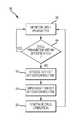
- control system 30if the various drill parameters monitored by the control system 30 are within specifications for the various drill parameters, as determined during step 44 , then control system 30 takes no further action, other than to continue to operate the drill rig 16 to form blasthole 14 . That is, control system 30 will simply continue to monitor the various drill parameters at step 38 as the drilling operation proceeds. If, however, control system 30 determines that one or more of the drill parameters are not in accordance with the specified drill parameters, then control system 30 proceeds to step 46 , wherein control system 30 chooses or selects a defect mitigation routine, e.g., either a drilling phase defect mitigation routine 40 or a retraction phase defect mitigation routine 42 , as the case may be.
- a defect mitigation routinee.g., either a drilling phase defect mitigation routine 40 or a retraction phase defect mitigation routine 42 , as the case may be.
- control system 30will then implement the particular defect mitigation routine at step 48 .
- Control system 30implements the particular defect mitigation routine by operating the various systems of drill rig 14 in accordance with the teachings provided herein. After the particular defect mitigation routine has been implemented, the control system 30 will continue to operate the drill rig 16 in accordance with the particular phase (e.g., the drilling phase or the retraction phase) at step 50 .
- the particular phasee.g., the drilling phase or the retraction phase
- the system 10may be operated as follows to cause the drill rig 16 to drill a borehole 12 , such as a blasthole 14 , in a geologic structure 15 (i.e., the ground).
- a geologic structure 15i.e., the ground.
- the control system 30may initiate the drilling phase of operation.
- the control system 30operates the drill motor 22 , drill hoist 24 , air injection system 26 , and water injection system 28 to begin rotating and driving the drill bit 32 into the ground or geologic formation 15 .
- the control system 30monitors (i.e., at step 38 ) the various drill parameters that are generated or produced by the various systems comprising drill rig 16 .
- certain drill parametersare indicative of certain issues during drilling that, if properly managed, can mitigate or lessen the possible adverse effects such issues may have on borehole quality.
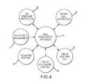
- the control system 30may monitor drill parameters such as air pressure, drill rotational speed, drill torque, drill depth, and the number of times the drill has been retracted during the drilling phase. The control system 30 compares these various drill parameters with predetermined specifications for the respective parameters. If one or more of the drill parameters is outside the predetermined specification, the control system 30 chooses and implements one or more drilling phase defect mitigation routines 40 , as best seen in FIG. 4 .
- the various drilling phase defect mitigation routines 40comprise an air pressure protection routine 52 , a rotary stall protection routine 54 , an end-of-hole spin-out routine 56 , an end-of-hole measurement routine 57 , and an end-of-hole water control routine 58 .
- the drilling phase defect mitigation routines 40may also comprise a collaring routine 60 .
- the collaring routine 60is automatically performed at the start of each borehole 12 . That is, in one embodiment, the selection and implementation of the collaring routine 60 is not dependent on whether or not any drill parameter is within the predetermined specification.
- the collaring routine 60creates a high quality collar 62 (e.g., the first 1-3 meters of the borehole 12 ).
- the air pressure protection routine 52detects a failing borehole 12 by monitoring the air pressure at the drill bit 32 . If the air pressure exceeds the predetermined specification, then the drill bit 32 is retracted to clear the obstruction in the borehole 12 .
- the rotary stall protection routine 54is useful in detecting fractures or broken-up ground being engaged by the drill bit 32 . That is, when the drill bit 32 encounters broken or unstable ground, the bit 32 will typically stall out (i.e., cease to rotate). The rotary stall protection routine 54 detects these stalls and retracts the drill bit 32 to allow it to rotate again.
- the end-of-hole spin-out routine 56monitors the number of times the bit 32 needs to be retracted from the borehole 12 during the drilling phase and uses that number as a basis for determining how long to spend at the bottom of the borehole 12 clearing out any cuttings 34 before retracting the bit 32 from the borehole 12 .
- the end-of-hole measurement routine 57may be used to confirm that the borehole 12 will drilled to the prescribed depth.
- the end-of-hole water control routine 58deactivates the water injection system 28 to allow the dry cuttings 34 being created without water injection to build up a coating on the inside of the borehole 12 . The coating helps to reduce the amount of cuttings 34 that can fall back into the borehole 12 as the drill bit 32 is subsequently retracted.
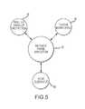
- the control system 30may also utilize a variety of retraction phase mitigation routines 42 ( FIG. 5 ) during the retraction phase of drilling, i.e., when the drill bit 32 is being retracted from the borehole 12 .
- the retraction phase mitigation routines 42comprise a drill bit hang-up protection routine 64 , a torque monitoring routine 66 , and a hole clean-out routine 68 . See FIG. 5 .
- the control system 30selects or chooses from among the various retraction phase defect mitigation routines 42 based on one or more monitored drill parameters consisting of drill rotational speed, drill torque, hoist speed, and number of drill retractions.
- the control system 30monitors the hoist speed as well as the rotation speed and torque applied to drill bit 32 . If these drill parameters are out of specification, the control system 30 will implement the drill bit hang-up protection routine 64 to free the bit and implement the hole clean-out routine 68 .
- the torque monitoring routine 66detects bad spots in the borehole 12 by monitoring the torque applied to the rotating drill bit 32 as the bit 32 is withdrawn from the borehole 12 . If the torque exceeds or is outside the predetermined torque parameter, the control system 30 will implement the hole clean-out routine 68 .
- the hole clean-out routine 68involves re-lowering the drill bit 32 to the bottom of the borehole 12 , where the spin-out routine 56 is applied. The bit 32 will then be retracted once again.
- a significant advantage of the present inventionis that may be used to produce high quality boreholes 12 , i.e., boreholes 12 that are compliant with the desired borehole specification. Moreover, not only is initial hole quality increased, i.e., the percentage of boreholes that are compliant with the desired specification immediately after formation, but long-term hole quality is increased as well. That is, the various defect mitigation routines help to minimize the likelihood that post-drilling events, such as cave-ins, will cause otherwise compliant blastholes 14 to become non-compliant before they can be filled with explosives.
- the present inventionis able to implement the various defect mitigation routines 40 and 42 on an as-needed basis. That is, the various defect mitigation routines are not automatically implemented on every borehole 12 .
- the selective implementation of the various defect mitigation routines 40 and 42allows the boreholes 12 to be formed as rapidly as possible, while still allowing for the formation of high quality boreholes 12 .
- the various hole defect mitigation routines 40 and 42are only implemented when they are needed, e.g., due to defects in the geologic structure 15 . They are not implemented in areas where the geologic structure 15 will allow the formation of high quality boreholes without the need to implement any defect mitigation routines.
- Yet another advantage of the present inventionis that it selects and applies different hole defect mitigation routines depending on the type of defects that are encountered during drilling.
- the present inventionis thus able to apply the defect mitigation routine that is most appropriate for addressing the particular defects in the geologic structure 15 that are encountered when drilling each particular borehole 12 .
- the present inventionmaximizes both initial and long-term borehole quality.
- the quality of the hole collar 12will always be uniformly high.
- the present inventionmay also be used in other applications besides mining and quarrying operations. Indeed, the present invention could be used in any application wherein it would be desirable to form boreholes of consistent quality or otherwise compensate for variations in the geologic structure in which the boreholes are formed. Consequently, the present invention should not be regarded as limited to the particular devices, systems, and applications shown and described herein.
- the system 10 for forming boreholes 12is shown and described herein as may be used to drill or form a plurality of boreholes 12 of the type used in open-pit mining operations.
- the various boreholes 12are filled with an explosive material that, when detonated, ruptures or fractures the geologic structure 15 .
- the fractured materialmay then be removed and processed to recover the valuable mineral content.
- the drill rig 16 that is used to form the blastholes 14comprises a mast or derrick 18 that is configured to support the drill string 20 that is used to drill or form the blastholes 14 .
- Drill rig 16may also comprise various other systems, such as a drill motor system 22 , a drill hoist system 24 , an air injection system 26 , and a water injection system 28 , required to operate the drill string 20 to form the blastholes 14 .
- a control system 30operatively connected to drill rig 16 and the various systems comprising drill rig 16 monitors drill parameters and controls the various systems in the manner described herein.
- Drill rig 16will also comprise a number of additional systems and devices, such as one or more power plants, electrical systems, hydraulic systems, pneumatic systems, etc. (not shown), that may be required or desired for the operation of the particular drill rig 16 .
- additional systems and devicesare well known in the art and are not required to understand or implement the present invention, such additional systems and devices that may be utilized in any particular drill rig 16 will not be described in further detail herein.
- drill motor system 22is operatively connected to drill string 20 and provides the rotational force or torque required to rotate drill bit 32 mounted on the end of drill string 20 .
- drill motor system 22will comprise an electrically- or hydraulically-powered system that is reversible so that the drill bit 32 can be rotated in either the clockwise or counterclockwise direction.
- the drill motor system 22is capable of automatic or semi-automatic operation, and will usually be provided with various sensors and transducers (not shown) suitable for sensing and producing output signals or data relating to various aspects and operational states of the drill motor system 22 .
- drill motor system 22is provided with sensors or transducers suitable for allowing the control system 30 to monitor the torque applied to drill bit 32 , as well as the rotational speed and rotational direction of drill bit 32 .
- sensors or transducerssuitable for providing the required drill parameter data to control system 30 . If not, suitable sensors or transducers would need to be provided.
- drill motors for drill rigsare well-known in the art, and because a more detailed description of such drill motor systems 22 is not required to understand or practice the invention, the particular drill motor system 22 that may be utilized in conjunction with the present invention will not be described in further detail herein.
- Drill rig 16may also be provided with a drill hoist system 24 that is also operatively associated with the drill string 20 and control system 30 , as best seen in FIG. 2 .
- the drill hoist system 24applies axial or hoisting forces to the drill string 20 to raise and lower the drill bit 32 .
- the drill hoist system 24may be electrically or hydraulically powered and may be configured to apply axial forces to the drill string 20 in both directions, i.e., to provide both “pull-up” (i.e., retraction) and “pull-down” (i.e., extension) forces to the drill bit 32 .
- the drill hoist system 24is also capable of automatic or semi-automatic operation and may be provided with various sensors and transducers (not shown) suitable for sensing and producing signals relating to various aspects and operational states of the drill hoist system 24 .
- the control system 30monitors hoisting forces (e.g., both pull-up and pull-down forces) applied to drill string 20 , as well as the vertical position or depth of the drill bit 32 . Consequently, the drill hoist system 24 should be capable of providing such information to the control system 30 . If not, suitable sensors or transducers would need to be provided.
- the air injection system 26 of drill rig 16is operatively connected to the drill string 20 and provides high-pressure air to the drill string 20 .
- the high-pressure air from air injection system 26is directed through a suitable conduit (not shown) provided in the drill string 20 , and ultimately exits through one or more openings provided in the drill bit 32 .
- the control system 30 of the present inventionis operatively connected to the air injection system 26 so that it can control the operation thereof.
- control system 30also monitors the air pressure provided to the drill string 20 .
- the air injection system provided on a typical drill rigwill be capable of providing air pressure data to the control system 30 . If not, such systems could be readily provided by persons having ordinary skill in the art after having become familiar with the teachings provided herein.
- Drill rig 16may also be provided with a water injection system 28 suitable for providing water (or other suitable drilling fluid) to the drill bit 32 . Similar to the air injection system 26 , pressurized water from the water injection system may be directed through a suitable conduit (not shown) provided in the drill string 20 before ultimately exiting through one or more openings provided in the drill bit 32 .
- Control system 30is operatively connected to the water injection system 28 and controls the function and operation thereof.
- control system 30does not monitor any parameters of the water injection system 28 other than its operational state (e.g., whether the system is “on” or “off”), although provisions could be made to allow the control system 30 to monitor other parameters (e.g., water pressure and flow rate) of the water injection system 28 , if desired.
- control system 30In addition to being connected to the various systems of drill rig 16 so that control system 30 can monitor various drill parameters and control the function and operation of the various systems, control system 30 also stores program steps for program control in computer-readable medium 31 , and (e.g., through processor 33 ), processes data, and selects and implements the various hole defect mitigation routines described herein. Accordingly, control system 30 may comprise any of a wide variety of systems and devices suitable for performing these functions, as would become apparent to persons having ordinary skill in the art after having become familiar with the teachings provided herein. Consequently, the present invention should not be regarded as limited to a control system 30 comprising any particular device or system.
- control system 30may comprise a general purpose programmable computer, such as a personal computer (e.g., processor 33 ), that is programmed with instructions embedded in computer-readable medium 31 to implement the various processes and steps described herein and that can interface with the particular systems provided on drill rig 16 .
- a general purpose programmable computersuch as a personal computer (e.g., processor 33 )
- processor 33e.g., a central processing unit
- control system 30may comprise a general purpose programmable computer, such as a personal computer (e.g., processor 33 )
- a general purpose programmable computersuch as a personal computer (e.g., processor 33 )
- processor 33e.g., a personal computer
- the particular programmable computer system that may comprise control system 30will not be described in further detail herein.
- the control system 30may be programmed to implement a method 36 for drilling the boreholes 12 .
- the control system 30monitors the drill parameters associated with the drill rig 16 .
- Control system 30may do this via a suitable data interface (not shown) provided between control system 30 and the various sensors or transducers associated with the various systems of drill rig 16 . If the various drill parameters monitored by the control system 30 are within the specifications for the various drill parameters, as determined during step 44 , the control system 30 will take no further action, other than to continue to operate the various systems of drill rig 16 as required to form the blast hole 14 . The control system 30 will continue to monitor the various drill parameters at step 38 .
- control system 30determines that one or more of the drill parameters being monitored is not in accordance with the specified parameter, then control system 30 will proceed to step 46 , wherein the control system 30 chooses or selects a defect mitigation routine.
- control system 30will depend on the particular drill parameter that is not within specification, as well as on whether the control system is operating the drill rig 16 in the drilling phase or the retraction phase. If the control system 30 is operating the drill rig 16 in the drilling phase, control system 30 will choose or select from among the various drilling phase defect mitigation routines 40 illustrated in FIG. 4 . On the other hand, if the control system 30 is operating the drill rig 16 in the retraction phase, control system 30 will choose or select from among the various retraction phase defect mitigation routines 42 illustrated in FIG. 5 .
- control system 30will then implement the particular defect mitigation routine at step 48 .
- the control system 30implements the selected defect mitigation routine by operating the various systems of drill rig 16 in the manner described below. After the defect mitigation routine has been implemented, the control system 30 will continue to operate the drill rig 16 at step 50 until the borehole 12 is completed.
- the drilling phase defect mitigation routines 40comprise an air pressure protection routine 52 , a rotary stall protection routine 54 , an end-of-hole spin-out routine 56 , and end-of-hole measurement routine 57 , an end-of-hole water control routine 58 , and a collaring routine 60 . See FIG. 4 .
- the collaring routine 60is performed automatically for every borehole 12 . That is, the selection of the collaring routine is not based on whether any particular drill parameter being monitored is outside specification. Accordingly, the collaring routine 60 will be described first, followed by the other drill phase defect mitigation routines 52 , 54 , 56 , 57 , and 58 .
- the collaring routine 60involves the formation of the collar 62 of the borehole 12 .
- the collar 62is regarded as the first 1-3 meters (about 2-10 feet) of the borehole 12 .
- the collaring phaseis perhaps the most important phase in blasthole formation. If the hole collar 62 is not properly prepared, both the hole quality and drill rig production will be adversely affected.
- a number of factors or conditionscan adversely affect the quality of the borehole 12 .
- steep piles 70 of cuttings 34 deposited on the surface 72 adjacent the borehole 12can result in back-filling of the borehole 12 after completion.
- Excessive friction between the drill string 20 and the wall 74 of borehole 12can result in wall failure, crooked boreholes, and poor borehole quality overall.
- the borehole 12may also be plugged if the collar 62 is too narrow, particularly near the top of the borehole 12 .
- the productivity of the drill rig 16also can be adversely affected if the hole collar 62 is not properly prepared.
- back-filling or even complete plugging of the borehole 12means that the drill rig 16 will need to clear the borehole 12 of obstructions, often more than once.
- Crooked boreholes 12will typically create excessive friction between the drill string 20 and the borehole wall 74 , resulting in the inefficient delivery of power to the drill bit 32 .
- crooked boreholes 12 and excessive frictioncan damage the drill rig 16 over time, resulting in increased maintenance costs and poor drill rig performance.
- the collaring routine 60involves a two-phase process to form a high quality hole collar 62 .
- the first phase 76 of the collaring routine 60advances the drill bit 32 to a predetermined depth (i.e., a set depth which represents the maximum collaring depth) at step 78 .
- a predetermined depthi.e., a set depth which represents the maximum collaring depth
- maximum collaring depthmay be selected to be in a range of about 1-3 meters (about 2-10 feet), although other depths may be used.
- collaring routine 60may advance the drill bit 32 to a depth that is determined to consist of competent rock, at step 80 .
- Competent rockmay be determined if the drill penetration rate falls below a predetermined level for a predetermined period of time.
- This alternative step 80may also be referred to herein as “dynamically determined collaring depth,” in that the depth of the collar 62 is not fixed, but rather is based on the particular characteristics of the geologic structure 15 in which the borehole 12 is being drilled.
- operating the collaring routine 60 in conjunction with this second optioni.e., step 80 ) may be advantageous in certain circumstances.
- first phase 76 of collaring routine 60cuttings 34 will typically build-up in a steep pile 70 on the surface 72 , as best seen in FIG. 7 .
- collar plugs 82it is common for collar plugs 82 to form in borehole 12 at a distance of about half a meter (e.g., about 1 foot) below the surface 72 . Both of these conditions are detrimental to hole quality as broken material that would normally lay clear of the borehole 12 has a tendency to fall back into the borehole 12 .
- the second phase 84 of collaring routine 60may be used to remedy these problems.
- the second phase 84 of collaring routine 60involves the retraction of drill bit 32 to location above the ground or surface 72 , at step 86 .
- the control system 30activates the water injection system 28 . This causes mud to build up on the borehole wall 74 , thus stabilizing it.
- the control system 30continues to activate the water injection system 28 during the retraction process until the drill bit 32 is above the surface 72 . At this point, the control system 30 deactivates the water injection system 28 to terminate the flow of water.
- control system 30activates the air injection system 26 ( FIG. 2 ) to clear the ground of cuttings (i.e., at step 88 ).
- High pressure air, represented by arrows 89 , exiting holes (not shown) provided in the drill bit 32will be sufficient to blow the existing and normally steep pile 70 of cuttings 34 created in the first phase 76 away from the opening of borehole 12 .
- step 88creates a more spread out, shallow cuttings pile 90 that is sufficiently small or spread out to allow future cuttings 34 to pile up in such a way so as to greatly reduce the amount of cuttings 34 apt to fall back into the borehole 12 .
- implementation of the two-phase collaring routine 60results in a far more reliable borehole 12 that is less prone to failure due to back-filling after the drill rig 16 has left the site.
- any collar plug 82FIG. 7 ) that may have formed is cleared from the wall 74 of the borehole 12 thereby allowing future cuttings 34 to clear the hole at a high rate of speed, further ensuring that the cuttings 34 will land far enough away from the opening of borehole 12 to prevent hole failure due to backfilling.
- control system 30may operate the drill hoist 24 to lift the drill bit 32 above the surface 72 by at least about 15 cm (about 6 inches) before rotating the drill bit 32 and starting the borehole 12 .
- This lifting off of the ground and spinning of the drill bit 32 at the beginning of the collaring routine 60causes any large rocks that may be on or slightly below the surface 72 to be pushed out of the way.
- the collaring routine 60ensures that nothing will be in the way of the drill bit 32 that could cause it to be “kicked” sideways, thereby starting the borehole 12 in a crooked manner. If the borehole 12 is not straight when started, it will adversely affect the entire drilling process. In addition, crooked holes may also result in excessive friction between the drill string 20 and the wall 74 of borehole 12 , resulting in possible wall failures, short boreholes, and poor hole quality.
- the first phase 76 of the collaring routine 60may involve alternative option (e.g., step 80 ) for determining the depth of the hole collar 62 .
- Step 80basically allows the depth of the collar 62 to be dynamically determined based on the particular conditions of the geologic structure 15 where the borehole 12 is being drilled, rather than merely drilling to a set depth.
- step 80may be used to ensure that an adequate depth of the borehole 12 is collared (i.e., the collar 62 is of adequate length) without the loss of productivity that would otherwise result from the “over-collaring” of borehole 12 .
- the present inventiondetermines competent ground by monitoring the drilling rate, or rate of penetration, over a selected time period. Competent rock or ground is determined if the drill penetration rate falls below a predetermined level for a predetermined period of time. By way of example, in one embodiment, once the rate of penetration drops below about 1 meter per minute (about 2 feet per minute) for a period of about 30 seconds, competent ground is determined to have been reached. The control system 30 will then proceed to the second phase 84 of collaring operation 60 already described.
- the second phase 84 of collaring routine 60may also be provided with an optional step 87 that involves returning the bit 32 to the bottom of hole collar 62 after performing step 88 (i.e., clearing the ground of cuttings).
- optional step 87may be advantageous in any of a wide variety of circumstances and will help to improve hole quality.
- certain geologic conditionsmay result in a false or erroneous determination of competent rock (e.g., as may be determined during step 80 ) at the bottom of the hole collar 62 .
- competent rocke.g., as may be determined during step 80
- the presence of a large rock or other such material located at or near the bottom of the hole collar 62may result in the deflection of the drill bit 32 upon initiation of the normal drilling sequence, i.e., following the collaring routine 60 .
- Such “down collar” deflection of the drill string 20may cause the resulting borehole 12 to deviate from its intended path, even though the collar 62 was otherwise properly aligned.
- optional step 87will tend to minimize deflection and bowing of the drill string 20 as the drill bit 32 is lowered to the bottom of the collar 62 (i.e., in preparation for the normal drilling sequence).
- a reduction in bowing and deflection of the drill string 20will help to ensure that the drill string 20 and drill bit 32 will be properly oriented and aligned within collar 62 when the normal drilling sequence is initiated.
- the reduction or elimination of such bowing and deflection of the drill string 20will also tend to extend the life of the drill string 20 and preserve the integrity of the drill string pipe joints.
- the optional step 87involves lowering the drill string 20 into the hole collar 62 at reduced rotary and hoist speeds compared to those that would otherwise be used at the start of the normal drilling operation.
- the system 30will continue to lower the drill string 20 into the hole collar 62 at the reduced rates until the drill bit 32 has been lowered to the previously determined collaring depth (e.g., as determined by either step 78 or step 80 , as the case may be).
- the control system 30will then perform step 80 to confirm that competent ground was in fact reached during the formation of the original hole collar 62 .
- step 80 as a part of step 87will be performed for the first time if the collar 62 was originally drilled to a set depth, i.e., by performing step 78 .
- the performance of step 80 as a part of step 87will be the second time step 80 is performed during the collaring routine 60 .
- step 87will be complete, and the system 30 will then proceed with the normal drilling operation, i.e., without retracting drill string 20 from the hole collar 62 .
- competent groundwas not reached, e.g., if the original determination of competent ground was in error, the control system 30 will continue to operate drill 20 in accordance with step 80 until competent ground is determined. Thereafter, the normal drilling process will be initiated.
- step 87involves lowering the drill string 20 into the hole collar 62 at reduced rotary and hoist speeds. These reduced speeds minimize the likelihood that the drill bit 32 or drill string 20 will damage the wall of the hole collar 62 as the drill bit 32 is lowered to the bottom of the hole collar 62 .
- the drill speedis reduced to a value that is in a range of about 30% to about 50% of the normal drill speed for the particular material involved. Alternatively, other reduced drill speeds could also be used.
- the reduced hoist speed during optional step 87is about 3 m/min (about 10 ft/minute), although other reduced hoist speeds could also be used.
- the pull-down force of the drill hoist system 24may be selected so that it is substantially identical to the pull-down force applied to drill string 20 during the collaring routine 60 , although lower pull-down forces could also be used.
- control system 30may initiate normal drilling operations in order to drill the borehole 12 to the desired depth. During the normal drilling operation, control system 30 will continue to monitor the various drilling parameters and implement the various drilling phase defect mitigation routines 40 illustrated in FIG. 4 .
- One of those defect mitigation routines 40is the air pressure protection routine 52 .
- the air pressure protection routine 52serves two primary purposes: To provide plugged bit detection and prevention and to provide collapsed hole detection and protection. Both purposes are relevant to hole quality. Plugged bit protection ensures that proper air flow is being provided to the bottom of the borehole 12 to ensure adequate bailing of drill cuttings 34 . Without this protective functionality, a plugged drill bit 34 would result in inadequate bailing of drill cuttings 34 , causing them to remain in the borehole 12 rather than being bailed out of the borehole 12 . In addition, improper bailing velocities can cause erosion of the borehole walls 74 , which can lead to wall failure and shallow boreholes 12 .
- the drill parameter that will cause the control system to select and implement the air pressure protection routine 52is the air pressure supplied to the drill string 20 . If the air pressure is normal, the control system 30 simply continues the normal drilling operation and continues to monitor the air pressure. If the air pressure exceeds the maximum amount, as determined by comparing the monitored air pressure with the predetermined value for air pressure, the control system 30 will follow the various procedures and decision paths set forth in FIG. 9 . Basically, the procedures and decision paths involve control of the water injection system 28 as well as the retraction of the drill bit 32 and the resumption of the drilling operation. If the various procedures and decisions paths are unable to clear the plugged drill bit 32 , the system will provide a plugged bit indication to the system operator and will stop the drilling process.
- the rotary stall protection routine 54detects and mitigates problems likely to arise from various sub-surface fractures 92 that may be contained in the geologic structure 15 that are being penetrated by drill string 20 .
- Sub-surface fracturing of the rock or geologic structure 15tends to be very detrimental to borehole quality in that, as the drill bit 32 penetrates the fractured area 92 , the drilling process causes the fractured area 92 to further break apart or loosen at the wall 74 of the borehole 12 .
- the loosened or broken materialhas the potential for falling into the borehole 12 after the drill rig 16 has left the borehole 12 upon completion of the drilling process. This situation must be mitigated in order to ensure quality boreholes 12 that will stand up over a period of time.
- the rotary stall protection routine 54detects these fractured areas 92 due to the probability of bit stalling when penetrating the fracture areas 92 . More specifically, as the broken or fractured area 92 is penetrated by drill bit 32 , the loose rock breaks apart in large pieces that often become wedged between the drill string 20 and borehole wall 74 . This wedging of broken material causes the drill string to stop rotating and thereby “stalls” the drill motor system 22 .
- the control system 30detects this stalled condition by monitoring the torque applied to drill bit 32 as well as its rotational speed. If the torque suddenly increases or spikes and the rotational speed suddenly drops, then control system 30 determines that the drill motor system 22 is stalling, as best seen in FIG. 10 .
- control system 30determines that the stalled condition has persisted for longer than some predetermined time, 1.5 seconds, for example, then the control system 30 will implement the rotary stall protection routine 54 . More specifically, control system 30 will operate drill hoist system 24 to retract the drill bit 32 to re-enable the rotation of drill bit 32 . If the rotational speed of the drill bit 32 does not recover within some period of time, for example within 3 seconds, the control system 30 will operate drill hoist system 24 to alternately apply pull-down and pull-up forces to the drill string 20 in an attempt to free drill bit 32 and allow it to rotate again.
- some predetermined time1.5 seconds
- control system 30will operate the hoist system 24 to slowly lower the bit 32 back to the bottom of the borehole 12 . Thereafter, control system 30 will reduce the pull-down force to avoid further stalling of the drill bit 32 . In addition, the control system 30 will increase the rotational speed of drill bit 32 to further assist in the grinding up of the broken particles from the fractured areas 92 .
- the reduction of pull-down force and increase in rotational speedis maintained until the drill rig 16 meets the following conditions (i.e., indicating that the drill bit 32 has passed the fractured area 92 ): There are no torque spikes for at least 15 seconds; and the rate of penetration has stopped changing (e.g., the penetration rate change over a time period of about 1 second is less than about 6 cm per minute (about 0.2 feet per minute)). Alternatively, other values for these parameters could be used. Once these conditions are met, the control system 30 increases the pull-down force to normal values. Control system 30 continues to monitor the drill parameters to ensure that the bit 32 is not going to stall again. In summary, then, by slowly penetrating the fractured areas 92 , further damage to the wall 74 of borehole 12 is avoided and a quality borehole 12 is further insured.
- the end-of-hole spin-out routine 56is illustrated in FIG. 12 .
- the control system 30will spin the drill bit 32 just above the bottom of the hole and allow all the cuttings 34 that have been created to be bailed from or exit the borehole 12 .
- the time required at the bottom of the borehole 12is variable and is determined by how much trouble the system 10 has encountered during the drilling phase. Basically, the monitored drill parameters will allow the control system to determine whether the particular borehole 12 is a “good” or a “bad” borehole, more precisely, whether the geologic structure 15 is stable or unstable.
- a good boreholeis defined as a borehole 12 that required the control system 30 to retract the drill bit 32 less than two (2) times during the drilling phase. If the control system 30 determines the borehole 12 to be good, then the end of the hole spin-out time will be 30 seconds, which will be sufficient in most instances to allow all cuttings 34 to be bailed from the borehole 12 .
- control system 30determines the borehole 12 to be bad, then control system calculates the spin-out time by multiplying by 30 seconds the number of times the bit 32 had to retracted. For example, if the bit 32 had to be retracted two times, then the spin-out time is determined or calculated to be sixty (60) seconds. Similarly, if the bit 32 had to be retracted three times, then the spin-out time is calculated to be ninety (90) seconds. In the embodiment shown and described herein, the maximum spin-out time is limited to two (2) minutes. Alternatively, of course, other maximum time limits could be set, as would become apparent to persons having ordinary skill in the art after having become familiar with the teachings provided herein.
- the end-of-hole spin-out routine 56also may be selected and implemented during the retraction phase of the drilling process. That is, if control system 30 detects a problem while retracting the bit, control system 30 will re-set the hole spin-out time. Control system 30 will then re-lower drill bit 32 to the bottom of the borehole 12 and perform again the end-of-hole spin-out routine 56 . If multiple passes are required to penetrate the hole, the end-of-hole spin-out time is accumulated accordingly.
- the end-of-hole water control routine 58is illustrated in FIG. 13 .
- the control system 30disables the water injection system 28 to allow dry cuttings 34 to attach to the wet walls 74 of the borehole 12 .
- the control system 30disables the water injection system 28 (i.e., turns off the flow of water) when the drill bit 32 is about 1 meter (about 3 feet) from the bottom of borehole 12 .
- other distancescould be used, as would become apparent to persons having ordinary skill in the art after having become familiar with the teachings provided herein.
- Implementing the end-of-hole water control routine 58causes a coating to be formed on the borehole wall 74 that helps to stabilize the borehole wall 74 . This coating significantly reduces the likelihood that loose rock will fall from the borehole wall 74 , further reducing the possibility of hole failure. Put another way, implementation of the end-of-hole water control routine 58 further mitigates any sub surface fractures that might transverse the borehole 12 .
- the control system 30may proceed directly to the retraction phase, as will be described below. Alternatively, however, the control system 30 may optionally perform an end-of-hole measurement routine 57 ( FIG. 4 ) before entering the retraction phase.
- the control system 30may choose or implement end-of-hole measurement routine 57 when the monitored drill depth meets a predetermined specification for drill depth (i.e., the prescribed depth).
- the end-of-hole measurement routine 57may be performed at some point during the retraction phase, as will also be described in greater detail below.
- the end-of-hole measurement routine 57may be used to determine the “as-drilled” depth of the borehole 12 . Ideally, step 57 will confirm that the borehole 12 was, in fact, drilled to the prescribed depth. However, there may be circumstances where the as-drilled depth of the borehole 12 will vary from the prescribed depth. If so, step 57 will detect this variance. The control system 30 may then resume the drilling process until the borehole 12 reaches the prescribed depth, as determined by monitoring the drill depth parameter. Step 57 can then be repeated until it is confirmed that the borehole 12 has been successfully drilled to the prescribed depth.
- the end-of-hole measurement routine 57involves a partial retraction of the drill string 20 from the borehole 12 .
- This partial retractionallows any loose or unstable material that would otherwise fall to the bottom of the borehole 12 (e.g., during the retraction phase) to fall to the bottom early, thereby allowing for a more accurate determination of borehole depth than would otherwise be the case if the system simply monitored the drill depth parameter during the drilling phase.
- the drill string 20is lowered (i.e., re-lowered) in borehole 12 .
- the control system 30monitors various drill parameters and compares them with corresponding set points. If the drill parameters fall outside the corresponding set points for a predetermined period of time, the control system will determine that the drill bit 32 has reached an “on ground position.”
- the “on ground position”is that position deemed to correspond to the bottom of the borehole 12 . For example, if the borehole 12 was free of cave-ins (i.e., if no material fell to the bottom of the borehole 12 while the drill string was in the partially retracted position), then the “on ground position” will be substantially equal to the prescribed borehole depth.
- Step 57may be repeated until the “on ground position” of the borehole is within the allowable depth variation.
- the drilling parameters measured during the process 57are the hoist speed, the pull-down force, and the drill torque. If all of these values fall outside the corresponding set points for the predetermined period of time, then the location at which this occurred is determined to be the “on ground position.” Alternatively, in another embodiment, the “on ground position” determination may be made at that location where at least one of the drilling parameters fell outside the corresponding set point for the predetermined period of time.
- the retraction distance, predetermined period time, the set points for the various drill parameters, and the allowable depth variation used in process 57may be selected during commissioning of the drilling system 10 . Consequently, the values may vary depending on a wide variety of factors, as would become apparent to persons having ordinary skill in the art after having become familiar with the teachings provided herein. Consequently, the present invention should not be regarded as limited to any particular values for these parameters.
- the drill string retraction distanceis selected to be about 25% of the prescribed borehole depth. Generally speaking, such a retraction distance will be sufficient to allow loose or unstable material to fall to the bottom of the borehole 12 . Alternatively, however, other retraction distances may be used, depending on the particular soil conditions or on other factors.
- the retraction distanceneed not comprise some percentage of prescribed borehole depth, but could instead comprise some fixed distance, such as 3 meters (about 10 feet).
- retraction of the drill string 20 by some fixed distancemay be less than desirable in certain circumstances. For example, if the prescribed borehole depth is only about 7.6 m (about 25 feet), then a partial retraction of the drill string 20 by the fixed distance of 3 m (about 10 feet), would be nearly 50% of the prescribed borehole depth, a greater retraction than is typically necessary. Conversely, if the prescribed borehole depth is about 15.2 m (about 50 feet), then a partial retraction of 3 m (about 10 feet), may not be sufficient to allow any loose or unstable material to fall to the bottom of the borehole.
- the set points for the various drill parametersalso may be determined during commissioning of the drill system 10 , thus may vary to some degree depending on the particular application and soil conditions. Consequently, the present invention should not be regarded as limited to any particular set points for the various parameters.
- the set point for hoist speedis selected to be about 6 m/min (about 20 ft/min)
- the set point for pull-down forceis selected to be about 89 kN (about 20,000 lbs).
- the rotational torque set pointis selected to be about 40% of maximum torque.
- the predetermined time periodmay be selected to be one (1) second, although other time periods could also be used.
- the hole depth variationmay be selected to be about 0.6 m (about 2 feet), although other values may be used, again depending on any of a wide variety of factors.
- the system 30determines that the drill bit 32 is “on ground position”. The system 30 then compares the “on ground position” depth with the prescribed borehole depth. If the difference exceeds 0.6 m (about 2 feet), then the system 30 will resume the drilling operation. If, on the other hand, the “on ground position” is within 0.6 m (about 2 feet) of the prescribed borehole depth, then the borehole 12 is deemed to have been drilled to the desired depth. The control system 30 may then proceed to the retraction phase.
- the retraction phaseis that phase of the drilling process during which the drill bit 32 is retracted from the bottom of the borehole 12 after reaching the desired depth.
- the retraction phaseis complete when the drill bit 32 is fully retracted from borehole 12 and the drill rig 16 ready to move to the next hole location.
- the retraction phase defect mitigation routines 42include a drill bit hang-up protection routine 64 , a torque monitoring routine 66 , and a hole clean-out routine 68 .
- the control system 30chooses and implements one or more of the various retraction phase defect mitigation routines 42 based on one or more monitored drill parameters of drill rotational speed, drill torque, hoist speed, and the number of drill retractions that were performed during the drilling phase.
- control system 30when retracting the rotation drill string 20 from the borehole 12 , control system 30 monitors the hoist speed (i.e., the speed at which the drill bit 32 is being retracted from borehole 12 ). Control system 30 also monitors the torque applied to the drill bit 32 as well as its rotation speed. Control system 30 compares these monitored drill parameters with predetermined specifications for these respective parameters during the retraction phase. If the bit retraction rate and rotational speed decline with a corresponding increase in torque, it is likely that material 98 has fallen from borehole wall 74 and is interfering with the rotating drill bit 32 , as illustrated in FIG. 16 . Once the drill bit 32 has been jammed or hung-up by material 98 , control system 32 implements or performs the various steps illustrated in FIG. 15 to mitigate the condition.
- the hoist speedi.e., the speed at which the drill bit 32 is being retracted from borehole 12 .
- Control system 30also monitors the torque applied to the drill bit 32 as well as its rotation speed. Control system 30 compares
- control system 30Upon concluding that the drill bit 32 has been hung-up or jammed by material 98 , the control system 30 first tries to free the drill bit 32 from the obstruction (i.e., material 98 ) encountered during retraction. More specifically, the control system 30 operates the drill motor system 22 ( FIG. 2 ) to apply maximum torque to the drill bit 32 in an attempt to cause the drill bit 32 to free itself from material 98 . Control system 30 also operates the drill hoist system 24 to reverse the hoist force applied to the drill string 20 . That is, control system 30 will stop applying a pull-up force to the drill string 20 and will instead apply a pull-down force to the drill string 20 . In one embodiment, control system 30 applies the pull-down force for a period of 3-5 seconds in an attempt to cause the drill bit 32 to be freed from the blockage.
- the obstructioni.e., material 98
- control system 30operates the drill hoist system 24 to alternately apply pull-up and pull-down forces to drill string 20 .
- the pull-up and pull-down forcesmay each be applied for a time period or cycle ranging from about 3 seconds to about 5 seconds, although other cycle times may also be used.
- control system 30activates the water injection system 28 in an attempt to use water to free the obstruction.
- the number of pull-up/pull-down cycles and the amount of water appliedmay vary depending on the particular application, as would become apparent to persons having ordinary skill in the art after having become familiar with the teachings provided herein. Consequently, the present invention should not be regarded as limited to any particular number of pull-up/pull-down cycles or any particular water flow.
- control system 30activates the water injection system 28 to provide 100% water flow if the drill bit 32 has not been freed after 5 pull-up/pull-down cycles.
- control system 30will terminate the retraction process. Control system 30 may then alert a system operator that it was not successful in freeing the drill bit 32 .
- control system 30operates drill hoist system 23 to hoist up the bit 32 at a greatly reduced rate of speed.
- Control system 30also operates drill motor system 22 to increase the bit rotation speed to maximum. This is done in an attempt to slowly bring the drill bit 32 above the blockage that exists. This slow retraction, combined with the high bit rotation speed allows the drill bit 32 to gradually break up the material 98 that has caused the blockage in borehole 12 .
- the reduced rate of speedis about 0.3 m per minute (about 1 foot per minute).
- the rotation rateis about 90 revolutions per minute (rpm), which is about 90% of maximum rpm in this example.
- rpmrevolutions per minute
- other reduced hoisting speeds and bit rotation ratesmay be used as well.
- control system 30may return to a normal retraction speed until the bit 32 has cleared the borehole 12 . Thereafter, control system 30 may implement the hole clean-out routine 68 .
- control system 30implements torque monitoring routine 66 during the retraction phase.
- control system 30monitors the torque applied by the drill motor system 22 as the drill bit 32 is being retracted from borehole 12 . If the torque varies by more than a predetermined amount within a predetermined time, then control system 30 will implement clean-out routine 68 ( FIG. 5 ).
- the variation in rotational torqueindicates that the drill bit 32 has contacted something that is sticking out from the drill wall 34 sufficiently far to cause interference with the drill bit 32 . Once contact is made sufficient to cause a variation in torque, it is assumed that the drill bit 32 has dislodged the obstruction and caused it, and possibly additional material, to fall to the bottom of the blast hole resulting in a shortened hole and thereby poor hole quality.
- torque variations as low as about 3 percent to about 7 percent that occur within about 500 milliseconds or lessare indicative of problems that are likely to adversely affect hole quality.
- the rotational torque monitoring routine 66will continue to trigger hole clean out routines 68 until no torque variations occur during the retraction phase.
- control system 30may terminate the retraction phase if more than a predetermined number of attempts have been made that would indicate that the borehole 12 is not possible to drill.
- the hole clean-out routine 68performs a “re-drill” of the borehole 12 from start to finish.
- the control system 30implements the hole clean-out routine 68 under the following conditions:
- the hole clean-out routine 68incorporates all processes, including the monitoring and implementation of the various hole defect mitigation routines 40 , used during the normal drilling phase. If any of the above conditions are triggered again during the re-drilling of the hole, the entire clean out process will be re-started after the current clean out process is completed. This will continue for some predetermined number of clean out attempts. Thereafter, the control system 30 will stop trying to clean the hole and will mark the borehole 12 as a possibly bad hole that will need to be checked, if desired.
- the predetermined number of clean-out attemptsis selected to be seven (7) and is user-adjustable. That is, the number may be varied by a user depending on a number of factors, such as, for example, the importance of forming a substantially defect-free borehole compared to the number of holes desired to be drilled within a given time frame.
- the end-of-hole measurement routine 57may be implemented at any point in the retraction phase, if desired. For example, if the hole was determined to be “bad” during the retraction phase, e.g., during the performance of the hole clean-out routine 68 , then the control system 30 may elect to again perform the end-of-hole measurement routine 57 to confirm that the borehole 12 remains at the prescribed depth.
- the performance of the end-of-hole measurement routine 57 at the conclusion of the hole clean-out routine 68may be substantially identical to the performance of routine 57 at the conclusion of the drilling phase already described above.
- the system 10may be operated as follows to cause the drill rig 16 to drill a borehole 12 , such as a blasthole 14 , in a geologic structure 15 (i.e., the ground).
- the system 10may be operated in a fully automatic mode wherein the system 10 automatically positions the drill rig 16 over the selected hole location and proceeds to automatically drill the borehole 12 in accordance with the teachings provided herein.
- the control system 30may initiate the drilling phase of operation.
- the control system 30operates the drill motor 22 , drill hoist 24 , air injection system 26 , and water injection system 28 to begin rotating and advancing the drill bit 32 into the ground or geologic formation 15 .
- the control system 30monitors (i.e., at step 38 ) the various drill parameters that are generated or produced by the various systems comprising drill rig 16 .
- the drill parameters monitored by control system 30include air pressure, drill rotational speed, drill torque, drill depth, and the number of times the drill has been retracted during the drilling phase.
- the control system 30compares these various drill parameters with predetermined specifications for the respective parameters. If one or more of the drill parameters is outside of the predetermined specification, the control system 30 chooses and implements one or more drilling phase defect mitigation routines 40 , as best seen in FIG. 4 .
- the control system 30will automatically implement the collaring routine 60 at the start of each borehole 12 . That is, in one embodiment, the selection and implementation of the collaring routine 60 is not dependent on whether any drill parameter is within the predetermined specification.
- the collaring routine 60creates a high quality collar 62 . Thus, automatically implementing the collaring routine 60 on every borehole 12 helps to ensure that each hole collar 62 will be of a high quality.
- control system 30will simply drill each borehole 12 in accordance with a developed drilling phase methods. That is, control system 30 may well drill a number of holes wherein none of the various drilling phase defect mitigation routines (with the exception of the collaring routine 60 ) will need to be implemented. On the other hand, and depending on which drill parameters are outside of specification, control system 30 may choose and implement one, several, or all of the drilling phase mitigation routines 40 on a single borehole 12 .
- control system 30will then operate the drill rig 16 in the retraction phase, i.e., withdraw the drill string 20 from the borehole 12 .
- Control system 30monitors various drill parameters during the retraction phase. Again, if none of the various parameters exceed or are outside the predetermined specifications for those parameters, then the drill string 20 is simply withdrawn from the borehole 12 . The drill rig 16 may then be moved or trammed to the location for the next borehole. On the other hand, if one or more of the drill parameters being monitored during the retraction phase exceed or are otherwise outside the corresponding predetermined specification, then control system 30 may implement one or more of the retraction phase defect mitigation routines 42 in the manner described herein.
Landscapes
- Life Sciences & Earth Sciences (AREA)
- Engineering & Computer Science (AREA)
- Geology (AREA)
- Mining & Mineral Resources (AREA)
- Physics & Mathematics (AREA)
- Environmental & Geological Engineering (AREA)
- Fluid Mechanics (AREA)
- General Life Sciences & Earth Sciences (AREA)
- Geochemistry & Mineralogy (AREA)
- Earth Drilling (AREA)
Abstract
Description
- The
drill bit 32 needed to be retracted more than twice during the drilling phase as a result of the implementation of the airpressure protection routine 52 or the rotarystall protection routine 54; - The implementation of the drill bit hang
protection routine 64; or - A rotational spike occurred (e.g., during the implementation of the torque monitoring routine66).
- The
Claims (34)
Priority Applications (1)
| Application Number | Priority Date | Filing Date | Title |
|---|---|---|---|
| US13/524,623US9316053B2 (en) | 2009-11-11 | 2012-06-15 | Methods and systems for drilling boreholes |
Applications Claiming Priority (3)
| Application Number | Priority Date | Filing Date | Title |
|---|---|---|---|
| US12/616,399US20110108323A1 (en) | 2009-11-11 | 2009-11-11 | Methods and systems for drilling boreholes |
| US12/940,577US8261855B2 (en) | 2009-11-11 | 2010-11-05 | Methods and systems for drilling boreholes |
| US13/524,623US9316053B2 (en) | 2009-11-11 | 2012-06-15 | Methods and systems for drilling boreholes |
Related Parent Applications (1)
| Application Number | Title | Priority Date | Filing Date |
|---|---|---|---|
| US12/940,577DivisionUS8261855B2 (en) | 2009-11-11 | 2010-11-05 | Methods and systems for drilling boreholes |
Publications (2)
| Publication Number | Publication Date |
|---|---|
| US20120253518A1 US20120253518A1 (en) | 2012-10-04 |
| US9316053B2true US9316053B2 (en) | 2016-04-19 |
Family
ID=43973310
Family Applications (7)
| Application Number | Title | Priority Date | Filing Date |
|---|---|---|---|
| US12/940,577ActiveUS8261855B2 (en) | 2009-11-11 | 2010-11-05 | Methods and systems for drilling boreholes |
| US13/524,631ActiveUS8261856B1 (en) | 2009-11-11 | 2012-06-15 | Methods and systems for drilling boreholes |
| US13/524,623Active2032-06-19US9316053B2 (en) | 2009-11-11 | 2012-06-15 | Methods and systems for drilling boreholes |
| US13/524,608ActiveUS8567523B2 (en) | 2009-11-11 | 2012-06-15 | Methods and systems for drilling boreholes |
| US14/045,553ActiveUS9194183B2 (en) | 2009-11-11 | 2013-10-03 | Methods and systems for drilling boreholes |
| US14/926,802Active2030-08-26US9995128B2 (en) | 2009-11-11 | 2015-10-29 | Methods and systems for drilling boreholes |
| US15/988,287ActiveUS10494868B2 (en) | 2009-11-11 | 2018-05-24 | Methods and systems for drilling boreholes |
Family Applications Before (2)
| Application Number | Title | Priority Date | Filing Date |
|---|---|---|---|
| US12/940,577ActiveUS8261855B2 (en) | 2009-11-11 | 2010-11-05 | Methods and systems for drilling boreholes |
| US13/524,631ActiveUS8261856B1 (en) | 2009-11-11 | 2012-06-15 | Methods and systems for drilling boreholes |
Family Applications After (4)
| Application Number | Title | Priority Date | Filing Date |
|---|---|---|---|
| US13/524,608ActiveUS8567523B2 (en) | 2009-11-11 | 2012-06-15 | Methods and systems for drilling boreholes |
| US14/045,553ActiveUS9194183B2 (en) | 2009-11-11 | 2013-10-03 | Methods and systems for drilling boreholes |
| US14/926,802Active2030-08-26US9995128B2 (en) | 2009-11-11 | 2015-10-29 | Methods and systems for drilling boreholes |
| US15/988,287ActiveUS10494868B2 (en) | 2009-11-11 | 2018-05-24 | Methods and systems for drilling boreholes |
Country Status (5)
| Country | Link |
|---|---|
| US (7) | US8261855B2 (en) |
| AU (1) | AU2010319730C1 (en) |
| BR (4) | BR122013028904B1 (en) |
| CL (1) | CL2012001220A1 (en) |
| WO (1) | WO2011059912A1 (en) |
Cited By (2)
| Publication number | Priority date | Publication date | Assignee | Title |
|---|---|---|---|---|
| US10062044B2 (en)* | 2014-04-12 | 2018-08-28 | Schlumberger Technology Corporation | Method and system for prioritizing and allocating well operating tasks |
| US11821272B2 (en) | 2020-03-02 | 2023-11-21 | Pason Systems Corp. | Detecting a mud motor stall |
Families Citing this family (30)
| Publication number | Priority date | Publication date | Assignee | Title |
|---|---|---|---|---|
| US8261855B2 (en) | 2009-11-11 | 2012-09-11 | Flanders Electric, Ltd. | Methods and systems for drilling boreholes |
| US9678508B2 (en) | 2009-11-16 | 2017-06-13 | Flanders Electric Motor Service, Inc. | Systems and methods for controlling positions and orientations of autonomous vehicles |
| PE20110521A1 (en) | 2009-12-02 | 2011-07-19 | Tech Resources Pty Ltd | A SYSTEM AND METHOD FOR THE AUTONOMOUS DRILLING OF HOLES IN THE GROUND |
| CL2013000281A1 (en)* | 2012-01-30 | 2014-08-18 | Harnischfeger Tech Inc | Monitoring methods of a mining machine that includes determining if the machine is operating in a first state, detecting a transition from the first state to a second operating state, generating messages that indicate parameters of machine operation in both states; mining machine monitor for the control of mining machines; a procedure for monitoring a mining drill; mining machine monitor for the monitoring of a mine drilling drill |
| CA2833730A1 (en) | 2012-11-19 | 2014-05-19 | Key Energy Services, Llc | Mechanized and automated well service rig system |
| CA2900101C (en) | 2014-08-13 | 2023-01-03 | Harnischfeger Technologies, Inc. | Automatic dust suppression system and method |
| AU2015350241B2 (en)* | 2014-11-17 | 2021-05-20 | Context Biopharma Inc. | Onapristone extended-release compositions and methods |
| US9890835B2 (en) | 2015-04-24 | 2018-02-13 | Allison Transmission, Inc. | Multi-speed transmission |
| CA2978272C (en) | 2015-05-08 | 2020-07-14 | Halliburton Energy Services, Inc. | Apparatus and method of alleviating spiraling in boreholes |
| AU2015398956A1 (en)* | 2015-06-17 | 2017-12-21 | Sandvik Mining And Construction Oy | Arrangement for controlling collaring drilling |
| SE542284C2 (en) | 2015-10-01 | 2020-04-07 | Epiroc Rock Drills Ab | Method and system for assigning tasks to mining and/or construction machines |
| US10428638B2 (en)* | 2016-12-06 | 2019-10-01 | Epiroc Drilling Solutions, Llc | System and method for controlling a drilling machine |
| US11333013B2 (en)* | 2016-12-28 | 2022-05-17 | Halliburton Energy Services, Inc. | Segmentation of time-frequency signatures for automated pipe defect discrimination |
| CN108625771B (en)* | 2017-03-20 | 2020-06-23 | 中国海洋石油集团有限公司 | Water curtain drilling hole optimal setting method based on dynamic judgment of water-rich characteristics of surrounding rock |
| US11162359B2 (en)* | 2017-06-27 | 2021-11-02 | Reflex Instruments Asia Pacific Pty Ltd | Method and system for acquiring geological data from a bore hole |
| US10605077B2 (en)* | 2018-05-14 | 2020-03-31 | Alfred T Aird | Drill stem module for downhole analysis |
| EP3698931A1 (en)* | 2019-02-20 | 2020-08-26 | Hilti Aktiengesellschaft | Drilling device with display and method and system for determining and displaying a quality level for hole cleaning |
| US11466556B2 (en) | 2019-05-17 | 2022-10-11 | Helmerich & Payne, Inc. | Stall detection and recovery for mud motors |
| AU2020205242B2 (en)* | 2019-07-19 | 2025-09-25 | Caterpillar Global Mining Equipment Llc | Collar control system for mobile drilling machines |
| US11401795B2 (en)* | 2019-07-19 | 2022-08-02 | Caterpillar Global Mining Equipment Llc | Collar control system for mobile drilling machines |
| US11591897B2 (en) | 2019-07-20 | 2023-02-28 | Caterpillar Global Mining Equipment Llc | Anti-jam control system for mobile drilling machines |
| US10808379B1 (en)* | 2019-08-28 | 2020-10-20 | Cciip Llc | Roadway access hole drill and a method of microtrenching using the drill to open an access hole in the roadway |
| US11713677B2 (en)* | 2019-11-19 | 2023-08-01 | Peck Tech Consulting Ltd. | Systems, apparatuses, and methods for determining rock mass properties based on blasthole drill performance data including compensated blastability index (CBI) |
| US11480014B2 (en)* | 2019-12-13 | 2022-10-25 | Caterpillar Global Mining Equipment Llc | Automatic force adjustment control system for mobile drilling machines |
| CN112465330B (en)* | 2020-11-23 | 2022-04-22 | 中煤科工集团重庆研究院有限公司 | Failure evaluation method for underground coal mine gas extraction drill hole |
| CA3196190A1 (en) | 2020-11-27 | 2022-06-02 | Gustav Mortzell | Arrangement of controlling drilling parameters during extraction of a drill string |
| US11199062B1 (en) | 2020-12-15 | 2021-12-14 | Caterpillar Global Mining Equipment Llc | Systems, methods, and apparatuses for identifying groundwater during rock drill cutting |
| WO2023035058A1 (en)* | 2021-09-09 | 2023-03-16 | Redpath Canada Limited | Drill cuttings measurement box and system for controlling pilot hole drilling |
| US12104483B2 (en) | 2023-01-18 | 2024-10-01 | Caterpillar Global Mining Equipment Llc | Automatic deck wrench engagement for drilling machines |
| CN116411964B (en)* | 2023-05-26 | 2024-01-02 | 中国矿业大学 | Hydraulic fracturing cutting cooperative device suitable for hard rock and use method |
Citations (104)
| Publication number | Priority date | Publication date | Assignee | Title |
|---|---|---|---|---|
| US2310001A (en) | 1940-03-27 | 1943-02-02 | Sullivan Machinery Co | Apparatus for cleaning holes |
| US3381761A (en) | 1964-10-14 | 1968-05-07 | Atlas Copco Ab | Automatic rock drilling means |
| US3525404A (en) | 1968-02-23 | 1970-08-25 | Hughes Tool Co | Rotary drilling rig with direct power drive and simplified controls |
| US3561542A (en) | 1969-03-20 | 1971-02-09 | Gardner Denver Co | Control system for rock drills |
| US3613805A (en) | 1969-09-03 | 1971-10-19 | Bucyrus Erie Co | Automatic control for rotary drill |
| US3666025A (en) | 1969-03-20 | 1972-05-30 | Gardner Denver Co | Collaring timing control system for rock drills |
| US3669197A (en) | 1969-03-20 | 1972-06-13 | Gardner Denver Co | Control system for rock drills |
| US3670826A (en) | 1970-09-11 | 1972-06-20 | Gardner Denver Co | Control system for drills |
| US3730285A (en) | 1971-10-08 | 1973-05-01 | Gardner Denver Co | Rock drill bit guide and mast stabilizer |
| US3870111A (en) | 1973-09-10 | 1975-03-11 | Reserve Mining Co | Feed rate control for jet piercer |
| GB1437442A (en) | 1973-07-19 | 1976-05-26 | Rock Fall Co Ltd | Flushing system for a drilling machine |
| US4074771A (en) | 1976-03-25 | 1978-02-21 | Joy Manufacturing Company | Rock drill |
| US4165789A (en) | 1978-06-29 | 1979-08-28 | United States Steel Corporation | Drilling optimization searching and control apparatus |
| US4182588A (en) | 1976-10-07 | 1980-01-08 | Burkart Robert C | Positive feed drill |
| US4334580A (en) | 1980-03-24 | 1982-06-15 | Geo Vann, Inc. | Continuous borehole formed horizontally through a hydrocarbon producing formation |
| US4354233A (en)* | 1972-05-03 | 1982-10-12 | Zhukovsky Alexei A | Rotary drill automatic control system |
| US4369848A (en) | 1978-05-11 | 1983-01-25 | Oy Tampella Ab | Control system for a rock drill |
| US4434861A (en) | 1981-01-07 | 1984-03-06 | Howeth David Franklin | Dust conveying and collecting system and method |
| US4466487A (en)* | 1982-02-01 | 1984-08-21 | Exxon Production Research Co. | Method and apparatus for preventing vertical movement of subsea downhole tool string |
| AU2396284A (en) | 1983-02-04 | 1984-12-06 | Oy Tampella Ab | Feed control on rock drilling machine |
| US4503918A (en) | 1982-06-22 | 1985-03-12 | Institut Cerac S.A. | Rock drilling apparatus |
| US4793421A (en) | 1986-04-08 | 1988-12-27 | Becor Western Inc. | Programmed automatic drill control |
| US4794534A (en) | 1985-08-08 | 1988-12-27 | Amoco Corporation | Method of drilling a well utilizing predictive simulation with real time data |
| US4809791A (en) | 1988-02-08 | 1989-03-07 | The University Of Southwestern Louisiana | Removal of rock cuttings while drilling utilizing an automatically adjustable shaker system |
| US4852399A (en) | 1988-07-13 | 1989-08-01 | Anadrill, Inc. | Method for determining drilling conditions while drilling |
| US5048620A (en) | 1989-08-07 | 1991-09-17 | Maher Kevin P | Method for air rotary drilling of test wells |
| US5125460A (en) | 1987-06-12 | 1992-06-30 | Behrens Robert N | Pneumatically actuated horizontal drilling apparatus having a plurality of drills |
| US5348106A (en) | 1991-01-03 | 1994-09-20 | Tamrock Oy | Method of drilling a hole in a rock |
| US5358058A (en) | 1993-09-27 | 1994-10-25 | Reedrill, Inc. | Drill automation control system |
| US5445229A (en) | 1994-09-12 | 1995-08-29 | Delima; Robert L. | Method and apparatus for drilling, cracking, and withdrawing earth cores |
| US5449047A (en) | 1994-09-07 | 1995-09-12 | Ingersoll-Rand Company | Automatic control of drilling system |
| US5474142A (en) | 1993-04-19 | 1995-12-12 | Bowden; Bobbie J. | Automatic drilling system |
| US5540292A (en) | 1978-06-12 | 1996-07-30 | Behrens; Robert N. | Pneumatically actuated horizontal drilling apparatus having a plurality of drills |
| US5592438A (en)* | 1991-06-14 | 1997-01-07 | Baker Hughes Incorporated | Method and apparatus for communicating data in a wellbore and for detecting the influx of gas |
| US5622232A (en)* | 1994-07-01 | 1997-04-22 | Harnischfeger Corporation | Blasthole drill with drill-through pipe rack |
| US5680906A (en)* | 1994-12-08 | 1997-10-28 | Noranda, Inc. | Method for real time location of deep boreholes while drilling |
| US5844133A (en) | 1996-08-21 | 1998-12-01 | Furukawa Co., Ltd. | Drilling control apparatus of rock drill |
| US5853052A (en)* | 1996-09-10 | 1998-12-29 | Inco Limited | Hydraulic drive for rotation of a rock drill |
| US5913371A (en) | 1997-03-05 | 1999-06-22 | Terra Ag Fuer Tiefbautechnik | Apparatus for controlling the feed drive of a boring mechanism for making earth bores |
| US6021377A (en) | 1995-10-23 | 2000-02-01 | Baker Hughes Incorporated | Drilling system utilizing downhole dysfunctions for determining corrective actions and simulating drilling conditions |
| US6152246A (en) | 1998-12-02 | 2000-11-28 | Noble Drilling Services, Inc. | Method of and system for monitoring drilling parameters |
| US6209661B1 (en) | 1996-11-27 | 2001-04-03 | Sandvik Tamrock Oy | Method and arrangement for controlling feed in rock drilling |
| US6216800B1 (en) | 1998-11-24 | 2001-04-17 | J. H. Fletcher & Co., Inc. | In-situ drilling system with dust collection and overload control |
| US6253860B1 (en) | 1996-06-25 | 2001-07-03 | Sandvik Tamrock Oy | Method and arrangement for controlling rock drilling |
| US20010050186A1 (en) | 1998-11-24 | 2001-12-13 | Wilson Henry E. | Enhanced computer control of in-situ drilling system |
| US20020074165A1 (en) | 2000-09-22 | 2002-06-20 | Chack Fan Lee | Drilling process monitor |
| US6439322B2 (en) | 1998-06-17 | 2002-08-27 | Beck, Iii August H. | Downhole hammer-type core barrel and method of using same |
| US20030056983A1 (en) | 1999-09-24 | 2003-03-27 | Vermeer Manufacturing Company | Underground drilling device and method employing down-hole radar |
| US6662110B1 (en) | 2003-01-14 | 2003-12-09 | Schlumberger Technology Corporation | Drilling rig closed loop controls |
| US20040040746A1 (en) | 2002-08-27 | 2004-03-04 | Michael Niedermayr | Automated method and system for recognizing well control events |
| US6866106B2 (en) | 1995-12-08 | 2005-03-15 | University Of Queensland | Fluid drilling system with flexible drill string and retro jets |
| US6868920B2 (en) | 2002-12-31 | 2005-03-22 | Schlumberger Technology Corporation | Methods and systems for averting or mitigating undesirable drilling events |
| US6938702B2 (en) | 2001-12-07 | 2005-09-06 | Sandvik Inteleectual Property Ab | Method and equipment for controlling operation of rock drilling apparatus |
| US20050193811A1 (en) | 2004-03-03 | 2005-09-08 | Halliburton Energy Services, Inc. | Method and system for detecting conditions inside a wellbore |
| US20050279532A1 (en) | 2004-06-22 | 2005-12-22 | Baker Hughes Incorporated | Drilling wellbores with optimal physical drill string conditions |
| US7048077B2 (en) | 2004-09-26 | 2006-05-23 | P.V. Tool, Inc. | Drilling machine with pneumatic control |
| US7090037B2 (en) | 2001-01-10 | 2006-08-15 | Shell Oil Company | Device for anchoring a drill string in a borehole |
| US20060272861A1 (en) | 2002-04-19 | 2006-12-07 | Hutchinson Mark W | Method for improving drilling depth measurements |
| US20070003382A1 (en) | 2005-06-03 | 2007-01-04 | J.H. Fletcher & Co., Inc. | Automated, low profile drilling/bolting module with automated stab jack |
| US20070007039A1 (en) | 2002-11-05 | 2007-01-11 | Sandvik Tamrock Oy | Arrangement for controlling rock drilling |
| US7198117B2 (en) | 2002-02-22 | 2007-04-03 | Sandvik Tamrock Oy | Method and arrangement for controlling percussion rock drilling |
| US20070102196A1 (en)* | 2005-11-04 | 2007-05-10 | Grey Bassinger | Downhole percussion tool |
| US7228899B2 (en) | 2003-02-14 | 2007-06-12 | Key Energy Services, Inc. | Warning device and method to prevent clutch burning |
| US7243735B2 (en) | 2005-01-26 | 2007-07-17 | Varco I/P, Inc. | Wellbore operations monitoring and control systems and methods |
| US20070185696A1 (en) | 2006-02-06 | 2007-08-09 | Smith International, Inc. | Method of real-time drilling simulation |
| US20070242565A1 (en) | 2005-11-21 | 2007-10-18 | Hall David R | Downhole Pressure Pulse Activated by Jack Element |
| WO2007138170A1 (en) | 2006-06-01 | 2007-12-06 | Sandvik Mining And Construction Oy | Rock drilling rig and method of controlling thereof |
| US20080000688A1 (en) | 2006-07-03 | 2008-01-03 | Mcloughlin Stephen John | Adaptive apparatus, system and method for communicating with a downhole device |
| US20080060851A1 (en) | 2006-09-08 | 2008-03-13 | Fudo Tetra Corporation | Drilling head, method of soil improvement work and apparatus thereof |
| US7350593B1 (en) | 2006-11-07 | 2008-04-01 | Schramm, Inc. | Electronically controlled earth drilling rig |
| US7422076B2 (en) | 2003-12-23 | 2008-09-09 | Varco I/P, Inc. | Autoreaming systems and methods |
| US20080271923A1 (en) | 2007-05-03 | 2008-11-06 | David John Kusko | Flow hydraulic amplification for a pulsing, fracturing, and drilling (PFD) device |
| WO2009002306A1 (en) | 2007-06-26 | 2008-12-31 | Atlas Copco Rock Drills Ab | Method and device for controlling a rock drill rig |
| WO2009029269A2 (en) | 2007-08-27 | 2009-03-05 | Vermeer Manufacturing Company | Devices and methods for dynamic boring procedure reconfiguration |
| US20090090555A1 (en) | 2006-12-07 | 2009-04-09 | Nabors Global Holdings, Ltd. | Automated directional drilling apparatus and methods |
| US20090132458A1 (en) | 2007-10-30 | 2009-05-21 | Bp North America Inc. | Intelligent Drilling Advisor |
| US20090126994A1 (en) | 2007-11-15 | 2009-05-21 | Tibbitts Gordon A | Method And System For Controlling Force In A Down-Hole Drilling Operation |
| US20090173540A1 (en) | 2008-01-03 | 2009-07-09 | Philip Wayne Mock | Anti-stall tool for downhole drilling assemblies |
| US7604070B2 (en) | 2004-09-24 | 2009-10-20 | Sandvik Mining And Construction Oy | Arrangement for controlling percussive rock drilling |
| US20090266608A1 (en) | 2008-04-26 | 2009-10-29 | Schlumberger Technology Corporation | Torsional resonance prevention |
| US20100044104A1 (en) | 2008-08-20 | 2010-02-25 | Zediker Mark S | Apparatus for Advancing a Wellbore Using High Power Laser Energy |
| AU2009300240A1 (en) | 2008-10-03 | 2010-04-08 | Halliburton Energy Services, Inc. | Method and system for predicting performance of a drilling system |
| US7694752B2 (en) | 2003-07-08 | 2010-04-13 | British Nuclear Fuels Plc | Dry drilling |
| WO2010042050A1 (en) | 2008-10-10 | 2010-04-15 | Atlas Copco Rock Drills Ab | A method and an arrangement for controlling a rock drill |
| US7717190B2 (en) | 2004-07-02 | 2010-05-18 | Sandvik Mining And Construction Oy | Method for controlling percussion device, software production, and percussion device |
| US7721816B1 (en) | 2003-07-08 | 2010-05-25 | J.H. Fletcher & Co. | Drilling/bolting machine having a manual operator input device with enable switch and related methods |
| US7762352B2 (en) | 2004-12-10 | 2010-07-27 | Atlas Copco Rock Drills Ab | Arrangement and method for controlling drilling parameters |
| US7762346B2 (en) | 2004-06-09 | 2010-07-27 | Atlas Copco Rock Drills Ab | Method and system for collaring |
| US7828083B2 (en) | 2006-04-21 | 2010-11-09 | Sandvik Mining And Construction Oy | Method of controlling operation of rock drilling rig, and rock drilling rig |
| US20110077924A1 (en)* | 2008-06-17 | 2011-03-31 | Mehmet Deniz Ertas | Methods and systems for mitigating drilling vibrations |
| US20110108324A1 (en) | 2009-11-11 | 2011-05-12 | Flanders Electric, Ltd. | Methods and systems for drilling boreholes |
| US20110108323A1 (en)* | 2009-11-11 | 2011-05-12 | Flanders Electric, Ltd. | Methods and systems for drilling boreholes |
| US7954558B2 (en) | 2007-10-16 | 2011-06-07 | Vermeer Manufacturing Company | Devices and methods for power control in horizontal directional drilling |
| US20110214920A1 (en)* | 2009-08-13 | 2011-09-08 | Vail Iii William Banning | Universal drilling and completion system |
| US20110220410A1 (en)* | 2008-10-14 | 2011-09-15 | Schlumberger Technology Corporation | System and method for online automation |
| US8136612B2 (en) | 2007-05-03 | 2012-03-20 | Vermeer Corporation | Constant-mode auto-drill with pressure derivative control |
| AU2009222482B2 (en) | 2008-09-30 | 2012-03-22 | Percision Energy Service, Inc. | Downhole drilling vibration analysis |
| US20120097449A1 (en) | 2009-06-26 | 2012-04-26 | Jarno Viitaniemi | Method And Apparatus For Controlling Rock Drilling |
| US20120118637A1 (en) | 2009-08-07 | 2012-05-17 | Jingbo Wang | Drilling Advisory Systems And Methods Utilizing Objective Functions |
| US20120130693A1 (en)* | 2009-08-07 | 2012-05-24 | Mehmet Deniz Ertas | Methods to Estimate Downhole Drilling Vibration Amplitude From Surface Measurement |
| US8210283B1 (en) | 2011-12-22 | 2012-07-03 | Hunt Energy Enterprises, L.L.C. | System and method for surface steerable drilling |
| US20120186873A1 (en) | 2009-10-05 | 2012-07-26 | Halliburton Energy Services, Inc. | Well drilling method utilizing real time response to ahead of bit measurements |
| US20120222900A1 (en)* | 2009-05-27 | 2012-09-06 | Halliburton Energy Services, Inc | Vibration detection in a drill string based on multi-positioned sensors |
| US9068432B2 (en)* | 2012-03-02 | 2015-06-30 | Schlumberger Technology Corporation | Automated survey acceptance in dynamic phase machine automation system |
Family Cites Families (3)
| Publication number | Priority date | Publication date | Assignee | Title |
|---|---|---|---|---|
| ZA932779B (en)* | 1993-04-21 | 1994-10-12 | Jarmo Uolevi Leppaenen | Control system for percussion drill |
| SE9502961D0 (en) | 1995-08-28 | 1995-08-28 | Atlas Copco Rocktech Ab | Drilling method and apparatus |
| CA2165936C (en)* | 1995-12-21 | 2000-09-26 | Bert Stahl | Method and apparatus for controlling diamond drill feed |
- 2010
- 2010-11-05USUS12/940,577patent/US8261855B2/enactiveActive
- 2010-11-08BRBR122013028904-6Apatent/BR122013028904B1/enactiveIP Right Grant
- 2010-11-08BRBR122013028913-5Apatent/BR122013028913B1/enactiveIP Right Grant
- 2010-11-08BRBR122013028906-2Apatent/BR122013028906B1/enactiveIP Right Grant
- 2010-11-08WOPCT/US2010/055808patent/WO2011059912A1/enactiveApplication Filing
- 2010-11-08AUAU2010319730Apatent/AU2010319730C1/enactiveActive
- 2010-11-08BRBR112012011271-6Apatent/BR112012011271B1/enactiveIP Right Grant
- 2012
- 2012-05-10CLCL2012001220Apatent/CL2012001220A1/enunknown
- 2012-06-15USUS13/524,631patent/US8261856B1/enactiveActive
- 2012-06-15USUS13/524,623patent/US9316053B2/enactiveActive
- 2012-06-15USUS13/524,608patent/US8567523B2/enactiveActive
- 2013
- 2013-10-03USUS14/045,553patent/US9194183B2/enactiveActive
- 2015
- 2015-10-29USUS14/926,802patent/US9995128B2/enactiveActive
- 2018
- 2018-05-24USUS15/988,287patent/US10494868B2/enactiveActive
Patent Citations (115)
| Publication number | Priority date | Publication date | Assignee | Title |
|---|---|---|---|---|
| US2310001A (en) | 1940-03-27 | 1943-02-02 | Sullivan Machinery Co | Apparatus for cleaning holes |
| US3381761A (en) | 1964-10-14 | 1968-05-07 | Atlas Copco Ab | Automatic rock drilling means |
| US3525404A (en) | 1968-02-23 | 1970-08-25 | Hughes Tool Co | Rotary drilling rig with direct power drive and simplified controls |
| US3561542A (en) | 1969-03-20 | 1971-02-09 | Gardner Denver Co | Control system for rock drills |
| US3666025A (en) | 1969-03-20 | 1972-05-30 | Gardner Denver Co | Collaring timing control system for rock drills |
| US3669197A (en) | 1969-03-20 | 1972-06-13 | Gardner Denver Co | Control system for rock drills |
| US3613805A (en) | 1969-09-03 | 1971-10-19 | Bucyrus Erie Co | Automatic control for rotary drill |
| US3670826A (en) | 1970-09-11 | 1972-06-20 | Gardner Denver Co | Control system for drills |
| US3730285A (en) | 1971-10-08 | 1973-05-01 | Gardner Denver Co | Rock drill bit guide and mast stabilizer |
| US4354233A (en)* | 1972-05-03 | 1982-10-12 | Zhukovsky Alexei A | Rotary drill automatic control system |
| GB1437442A (en) | 1973-07-19 | 1976-05-26 | Rock Fall Co Ltd | Flushing system for a drilling machine |
| US3870111A (en) | 1973-09-10 | 1975-03-11 | Reserve Mining Co | Feed rate control for jet piercer |
| US4074771A (en) | 1976-03-25 | 1978-02-21 | Joy Manufacturing Company | Rock drill |
| US4182588A (en) | 1976-10-07 | 1980-01-08 | Burkart Robert C | Positive feed drill |
| US4369848A (en) | 1978-05-11 | 1983-01-25 | Oy Tampella Ab | Control system for a rock drill |
| US5540292A (en) | 1978-06-12 | 1996-07-30 | Behrens; Robert N. | Pneumatically actuated horizontal drilling apparatus having a plurality of drills |
| US4165789A (en) | 1978-06-29 | 1979-08-28 | United States Steel Corporation | Drilling optimization searching and control apparatus |
| US4334580A (en) | 1980-03-24 | 1982-06-15 | Geo Vann, Inc. | Continuous borehole formed horizontally through a hydrocarbon producing formation |
| US4434861A (en) | 1981-01-07 | 1984-03-06 | Howeth David Franklin | Dust conveying and collecting system and method |
| US4466487A (en)* | 1982-02-01 | 1984-08-21 | Exxon Production Research Co. | Method and apparatus for preventing vertical movement of subsea downhole tool string |
| US4503918A (en) | 1982-06-22 | 1985-03-12 | Institut Cerac S.A. | Rock drilling apparatus |
| AU2396284A (en) | 1983-02-04 | 1984-12-06 | Oy Tampella Ab | Feed control on rock drilling machine |
| US4794534A (en) | 1985-08-08 | 1988-12-27 | Amoco Corporation | Method of drilling a well utilizing predictive simulation with real time data |
| US4793421A (en) | 1986-04-08 | 1988-12-27 | Becor Western Inc. | Programmed automatic drill control |
| US5125460A (en) | 1987-06-12 | 1992-06-30 | Behrens Robert N | Pneumatically actuated horizontal drilling apparatus having a plurality of drills |
| US4809791A (en) | 1988-02-08 | 1989-03-07 | The University Of Southwestern Louisiana | Removal of rock cuttings while drilling utilizing an automatically adjustable shaker system |
| US4852399A (en) | 1988-07-13 | 1989-08-01 | Anadrill, Inc. | Method for determining drilling conditions while drilling |
| US5048620A (en) | 1989-08-07 | 1991-09-17 | Maher Kevin P | Method for air rotary drilling of test wells |
| US5348106A (en) | 1991-01-03 | 1994-09-20 | Tamrock Oy | Method of drilling a hole in a rock |
| US5592438A (en)* | 1991-06-14 | 1997-01-07 | Baker Hughes Incorporated | Method and apparatus for communicating data in a wellbore and for detecting the influx of gas |
| US5474142A (en) | 1993-04-19 | 1995-12-12 | Bowden; Bobbie J. | Automatic drilling system |
| US5465798A (en) | 1993-09-27 | 1995-11-14 | Reedrill, Inc. | Drill automation control system |
| US5358058A (en) | 1993-09-27 | 1994-10-25 | Reedrill, Inc. | Drill automation control system |
| US5622232A (en)* | 1994-07-01 | 1997-04-22 | Harnischfeger Corporation | Blasthole drill with drill-through pipe rack |
| US5449047A (en) | 1994-09-07 | 1995-09-12 | Ingersoll-Rand Company | Automatic control of drilling system |
| US5445229A (en) | 1994-09-12 | 1995-08-29 | Delima; Robert L. | Method and apparatus for drilling, cracking, and withdrawing earth cores |
| US5680906A (en)* | 1994-12-08 | 1997-10-28 | Noranda, Inc. | Method for real time location of deep boreholes while drilling |
| US6021377A (en) | 1995-10-23 | 2000-02-01 | Baker Hughes Incorporated | Drilling system utilizing downhole dysfunctions for determining corrective actions and simulating drilling conditions |
| US6866106B2 (en) | 1995-12-08 | 2005-03-15 | University Of Queensland | Fluid drilling system with flexible drill string and retro jets |
| US6253860B1 (en) | 1996-06-25 | 2001-07-03 | Sandvik Tamrock Oy | Method and arrangement for controlling rock drilling |
| US5844133A (en) | 1996-08-21 | 1998-12-01 | Furukawa Co., Ltd. | Drilling control apparatus of rock drill |
| US5853052A (en)* | 1996-09-10 | 1998-12-29 | Inco Limited | Hydraulic drive for rotation of a rock drill |
| US6209661B1 (en) | 1996-11-27 | 2001-04-03 | Sandvik Tamrock Oy | Method and arrangement for controlling feed in rock drilling |
| US5913371A (en) | 1997-03-05 | 1999-06-22 | Terra Ag Fuer Tiefbautechnik | Apparatus for controlling the feed drive of a boring mechanism for making earth bores |
| US6439322B2 (en) | 1998-06-17 | 2002-08-27 | Beck, Iii August H. | Downhole hammer-type core barrel and method of using same |
| US6216800B1 (en) | 1998-11-24 | 2001-04-17 | J. H. Fletcher & Co., Inc. | In-situ drilling system with dust collection and overload control |
| US6637522B2 (en) | 1998-11-24 | 2003-10-28 | J. H. Fletcher & Co., Inc. | Enhanced computer control of in-situ drilling system |
| US20010050186A1 (en) | 1998-11-24 | 2001-12-13 | Wilson Henry E. | Enhanced computer control of in-situ drilling system |
| US6152246A (en) | 1998-12-02 | 2000-11-28 | Noble Drilling Services, Inc. | Method of and system for monitoring drilling parameters |
| US20030056983A1 (en) | 1999-09-24 | 2003-03-27 | Vermeer Manufacturing Company | Underground drilling device and method employing down-hole radar |
| US20020074165A1 (en) | 2000-09-22 | 2002-06-20 | Chack Fan Lee | Drilling process monitor |
| US7090037B2 (en) | 2001-01-10 | 2006-08-15 | Shell Oil Company | Device for anchoring a drill string in a borehole |
| US6938702B2 (en) | 2001-12-07 | 2005-09-06 | Sandvik Inteleectual Property Ab | Method and equipment for controlling operation of rock drilling apparatus |
| US7198117B2 (en) | 2002-02-22 | 2007-04-03 | Sandvik Tamrock Oy | Method and arrangement for controlling percussion rock drilling |
| US20060272861A1 (en) | 2002-04-19 | 2006-12-07 | Hutchinson Mark W | Method for improving drilling depth measurements |
| US20040040746A1 (en) | 2002-08-27 | 2004-03-04 | Michael Niedermayr | Automated method and system for recognizing well control events |
| US20070007039A1 (en) | 2002-11-05 | 2007-01-11 | Sandvik Tamrock Oy | Arrangement for controlling rock drilling |
| US6868920B2 (en) | 2002-12-31 | 2005-03-22 | Schlumberger Technology Corporation | Methods and systems for averting or mitigating undesirable drilling events |
| US6662110B1 (en) | 2003-01-14 | 2003-12-09 | Schlumberger Technology Corporation | Drilling rig closed loop controls |
| US7228899B2 (en) | 2003-02-14 | 2007-06-12 | Key Energy Services, Inc. | Warning device and method to prevent clutch burning |
| US7721816B1 (en) | 2003-07-08 | 2010-05-25 | J.H. Fletcher & Co. | Drilling/bolting machine having a manual operator input device with enable switch and related methods |
| US7694752B2 (en) | 2003-07-08 | 2010-04-13 | British Nuclear Fuels Plc | Dry drilling |
| US7422076B2 (en) | 2003-12-23 | 2008-09-09 | Varco I/P, Inc. | Autoreaming systems and methods |
| US20050193811A1 (en) | 2004-03-03 | 2005-09-08 | Halliburton Energy Services, Inc. | Method and system for detecting conditions inside a wellbore |
| US7762346B2 (en) | 2004-06-09 | 2010-07-27 | Atlas Copco Rock Drills Ab | Method and system for collaring |
| US20050279532A1 (en) | 2004-06-22 | 2005-12-22 | Baker Hughes Incorporated | Drilling wellbores with optimal physical drill string conditions |
| US7717190B2 (en) | 2004-07-02 | 2010-05-18 | Sandvik Mining And Construction Oy | Method for controlling percussion device, software production, and percussion device |
| US7604070B2 (en) | 2004-09-24 | 2009-10-20 | Sandvik Mining And Construction Oy | Arrangement for controlling percussive rock drilling |
| US7048077B2 (en) | 2004-09-26 | 2006-05-23 | P.V. Tool, Inc. | Drilling machine with pneumatic control |
| US7762352B2 (en) | 2004-12-10 | 2010-07-27 | Atlas Copco Rock Drills Ab | Arrangement and method for controlling drilling parameters |
| US7243735B2 (en) | 2005-01-26 | 2007-07-17 | Varco I/P, Inc. | Wellbore operations monitoring and control systems and methods |
| US20070003382A1 (en) | 2005-06-03 | 2007-01-04 | J.H. Fletcher & Co., Inc. | Automated, low profile drilling/bolting module with automated stab jack |
| US20070102196A1 (en)* | 2005-11-04 | 2007-05-10 | Grey Bassinger | Downhole percussion tool |
| US7464772B2 (en) | 2005-11-21 | 2008-12-16 | Hall David R | Downhole pressure pulse activated by jack element |
| US20070242565A1 (en) | 2005-11-21 | 2007-10-18 | Hall David R | Downhole Pressure Pulse Activated by Jack Element |
| US20070185696A1 (en) | 2006-02-06 | 2007-08-09 | Smith International, Inc. | Method of real-time drilling simulation |
| US7828083B2 (en) | 2006-04-21 | 2010-11-09 | Sandvik Mining And Construction Oy | Method of controlling operation of rock drilling rig, and rock drilling rig |
| WO2007138170A1 (en) | 2006-06-01 | 2007-12-06 | Sandvik Mining And Construction Oy | Rock drilling rig and method of controlling thereof |
| US20080000688A1 (en) | 2006-07-03 | 2008-01-03 | Mcloughlin Stephen John | Adaptive apparatus, system and method for communicating with a downhole device |
| US20080060851A1 (en) | 2006-09-08 | 2008-03-13 | Fudo Tetra Corporation | Drilling head, method of soil improvement work and apparatus thereof |
| US7651301B2 (en) | 2006-09-08 | 2010-01-26 | Fudo Tetra Corporation | Drilling head, method of soil improvement work and apparatus thereof |
| US7350593B1 (en) | 2006-11-07 | 2008-04-01 | Schramm, Inc. | Electronically controlled earth drilling rig |
| US20090090555A1 (en) | 2006-12-07 | 2009-04-09 | Nabors Global Holdings, Ltd. | Automated directional drilling apparatus and methods |
| US8136612B2 (en) | 2007-05-03 | 2012-03-20 | Vermeer Corporation | Constant-mode auto-drill with pressure derivative control |
| US20080271923A1 (en) | 2007-05-03 | 2008-11-06 | David John Kusko | Flow hydraulic amplification for a pulsing, fracturing, and drilling (PFD) device |
| WO2009002306A1 (en) | 2007-06-26 | 2008-12-31 | Atlas Copco Rock Drills Ab | Method and device for controlling a rock drill rig |
| WO2009029269A2 (en) | 2007-08-27 | 2009-03-05 | Vermeer Manufacturing Company | Devices and methods for dynamic boring procedure reconfiguration |
| US7954558B2 (en) | 2007-10-16 | 2011-06-07 | Vermeer Manufacturing Company | Devices and methods for power control in horizontal directional drilling |
| US20090132458A1 (en) | 2007-10-30 | 2009-05-21 | Bp North America Inc. | Intelligent Drilling Advisor |
| US20090126994A1 (en) | 2007-11-15 | 2009-05-21 | Tibbitts Gordon A | Method And System For Controlling Force In A Down-Hole Drilling Operation |
| US20090173540A1 (en) | 2008-01-03 | 2009-07-09 | Philip Wayne Mock | Anti-stall tool for downhole drilling assemblies |
| US8146680B2 (en) | 2008-01-03 | 2012-04-03 | Wwt International, Inc. | Anti-stall tool for downhole drilling assemblies |
| US20090266608A1 (en) | 2008-04-26 | 2009-10-29 | Schlumberger Technology Corporation | Torsional resonance prevention |
| US20110077924A1 (en)* | 2008-06-17 | 2011-03-31 | Mehmet Deniz Ertas | Methods and systems for mitigating drilling vibrations |
| US8589136B2 (en)* | 2008-06-17 | 2013-11-19 | Exxonmobil Upstream Research Company | Methods and systems for mitigating drilling vibrations |
| US20100044104A1 (en) | 2008-08-20 | 2010-02-25 | Zediker Mark S | Apparatus for Advancing a Wellbore Using High Power Laser Energy |
| AU2009222482B2 (en) | 2008-09-30 | 2012-03-22 | Percision Energy Service, Inc. | Downhole drilling vibration analysis |
| AU2009300240A1 (en) | 2008-10-03 | 2010-04-08 | Halliburton Energy Services, Inc. | Method and system for predicting performance of a drilling system |
| WO2010042050A1 (en) | 2008-10-10 | 2010-04-15 | Atlas Copco Rock Drills Ab | A method and an arrangement for controlling a rock drill |
| US20110220410A1 (en)* | 2008-10-14 | 2011-09-15 | Schlumberger Technology Corporation | System and method for online automation |
| US20120222900A1 (en)* | 2009-05-27 | 2012-09-06 | Halliburton Energy Services, Inc | Vibration detection in a drill string based on multi-positioned sensors |
| US20120097449A1 (en) | 2009-06-26 | 2012-04-26 | Jarno Viitaniemi | Method And Apparatus For Controlling Rock Drilling |
| US20120118637A1 (en) | 2009-08-07 | 2012-05-17 | Jingbo Wang | Drilling Advisory Systems And Methods Utilizing Objective Functions |
| US20120130693A1 (en)* | 2009-08-07 | 2012-05-24 | Mehmet Deniz Ertas | Methods to Estimate Downhole Drilling Vibration Amplitude From Surface Measurement |
| US20110214920A1 (en)* | 2009-08-13 | 2011-09-08 | Vail Iii William Banning | Universal drilling and completion system |
| US20120186873A1 (en) | 2009-10-05 | 2012-07-26 | Halliburton Energy Services, Inc. | Well drilling method utilizing real time response to ahead of bit measurements |
| US20110108323A1 (en)* | 2009-11-11 | 2011-05-12 | Flanders Electric, Ltd. | Methods and systems for drilling boreholes |
| US8261855B2 (en)* | 2009-11-11 | 2012-09-11 | Flanders Electric, Ltd. | Methods and systems for drilling boreholes |
| US8261856B1 (en)* | 2009-11-11 | 2012-09-11 | Flanders Electric, Ltd. | Methods and systems for drilling boreholes |
| US20120253519A1 (en) | 2009-11-11 | 2012-10-04 | Flanders Electric, Ltd. | Methods and systems for drilling boreholes |
| US20120253518A1 (en) | 2009-11-11 | 2012-10-04 | Flanders Electric, Ltd. | Methods and systems for drilling boreholes |
| US20120255775A1 (en) | 2009-11-11 | 2012-10-11 | Flanders Electric, Ltd. | Methods and systems for drilling boreholes |
| US20110108324A1 (en) | 2009-11-11 | 2011-05-12 | Flanders Electric, Ltd. | Methods and systems for drilling boreholes |
| US8210283B1 (en) | 2011-12-22 | 2012-07-03 | Hunt Energy Enterprises, L.L.C. | System and method for surface steerable drilling |
| US9068432B2 (en)* | 2012-03-02 | 2015-06-30 | Schlumberger Technology Corporation | Automated survey acceptance in dynamic phase machine automation system |
Non-Patent Citations (20)
| Title |
|---|
| "Blasthole Drilling in Open Pit Mining," First edition, Published 2009, pp. 25-30 and 170-175, Atlas Copco AB, SE-105 23, Stockholm, Sweden. www.atlascopco.com/blastholedrills. |
| "Military Well Drilling Field Manual," Part Two. Well Drilling, Chapter 5, "Well Drilling Methods," Stored on the Internet Archive Wayback Machine on Apr. 2, 2009, 42 pages, http://www.globalsecurity.org/military/library/policy/army/fm/5-484/CH5.htm. |
| "Motor Operations Manual," Fourth Edition (4.3), Published 2005, 132 pages, Cavo Drilling Motors, 2450 Black Gold Ct., Houston, TX 77073, USA. |
| "Operator Training Manual-SKSS-15-Blast-hole Drill Rig," Published Mar. 2004, 130 pages, Reedrill Australia Limited. |
| "Power Performance Drill Upgrades-TorqReg/Digital Drives Upgrade-ARDVARC (Advanced Rotary Drill Vector Automated Radio Control," Nov. 20, 2008, 43 pages, Flanders ElectricPresentation at the Western Mining Electrical Association Conference, Denver, CO, U.S.A. |
| "ROC F9C System Description, PMI NR: 9853 1121 01b," Manual, Published 2008, 102 pages, Atlas Copco Rock Drills AB, SE-105 23, Stockholm, Sweden. |
| "Rotary Blasthole Drilling Air Practices Handbook," Published 2004, 36 pages, Atlas Copco BHMT Inc., P.O. Box 531226, Grand Prairie, Texas, USA 75053-12226. |
| "Surface Drilling," Manual, 4th Edition, Published 2008, pp. 3-12, 51-54, and 79-80, Atlas Copco AB, SE-105 23, Stockholm Sweden, www.surfacedrilling.com. |
| Australian Drilling Manual, Third Edition, ISBN 0 949279 20 X, Published 1992, 56 pages, Australian Drilling Industry Training Committee Limited. |
| Fiscor, Steve, "Fully Automated Blasthole Drilling Becomes a Reality," Dec. 10, 2009, 7 pages, Engineering and Mining Journal&MJ News. |
| Glass, B. et al., "DAME: Planetary-Prototype Drilling Automation," Presented at 2007 NASA Science Technology Conference (NSTC2007), Jun. 19-21, 2007, 8 pages, University of Maryland University College, U.S.A., Published online at: http://esto.nasa.gov/conferences/nstc2007/papers/Glass-Brian-C2P1-NSTC-07-0102.pdf. |
| Grad, Paul S., "Running with Robotics, Step by Step, Rio Tinto's concept of highly autonomous mining is Materializing in Western Australia's Pilbara iron ore district," Published Feb. 26, 2010, 5 pages, World of Mining Professionals (WOMP), The Mining E-Journal Published in Association with Engineering and Mining Journal (E&MJ), 2010, vol. 1-February. |
| International Search Report dated Jan. 10, 2011 for PCT Application No. PCT/US2010/055808, 3 pages. |
| Lyons, Wiliam C., "Air and Gas Drilling Manual: Applications for Oil and Gas Recovery Wells and Geothermal Fluids," Published Jan. 15, 2009, pp. 206-207, http://books.google.com.au. |
| Non-Final Office Action dated Feb. 14, 2012 for U.S. Appl. No. 12/940,577, 13 pages. |
| Non-Final Office Action dated Jul. 15, 2011 for U.S. Appl. No. 12/616,399, 7 pages. |
| Non-Final Office Action dated Jul. 15, 2011 for U.S. Appl. No. 12/940,577, 13 pages. |
| Statement of Grounds and Particulars, In the Matter of Australian Patent Application No. 2010319730, Flanders Electric Motor Service, Inc. and Opposition thereto by Christopher John Carter, dated Jun. 11, 2015, amended Jun. 23, 2015, 14 pages. |
| Written Opinion of the International Searching Authority dated Jan. 10, 2011 for PCT Application No. PCT/US2010/055808, 7 pages. |
| Zink, Jr., Clarence R., Manager-Field Engineering, Baker Hughes Mining tools, Inc., Grand Prairie, Texas, "Bottom Hole Annular Pressure: A Theoretical Problem with Real Effects," Published Feb. 8-11, 1998, 24th Annual Conference on Explosives and Blasting Technique and 14th Annual Symposium on Explosives and Blasting Research, New Orleans, Louisiana, 18 pages, International Society of Explosive Engineers. |
Cited By (2)
| Publication number | Priority date | Publication date | Assignee | Title |
|---|---|---|---|---|
| US10062044B2 (en)* | 2014-04-12 | 2018-08-28 | Schlumberger Technology Corporation | Method and system for prioritizing and allocating well operating tasks |
| US11821272B2 (en) | 2020-03-02 | 2023-11-21 | Pason Systems Corp. | Detecting a mud motor stall |
Also Published As
| Publication number | Publication date |
|---|---|
| CL2012001220A1 (en) | 2013-05-10 |
| US8261855B2 (en) | 2012-09-11 |
| BR122013028906B1 (en) | 2022-04-19 |
| BR122013028904A2 (en) | 2020-12-08 |
| US8261856B1 (en) | 2012-09-11 |
| US9995128B2 (en) | 2018-06-12 |
| US20160053602A1 (en) | 2016-02-25 |
| BR122013028904B1 (en) | 2022-04-19 |
| AU2010319730B2 (en) | 2014-11-13 |
| AU2010319730C1 (en) | 2016-07-14 |
| US20180266235A1 (en) | 2018-09-20 |
| US10494868B2 (en) | 2019-12-03 |
| US20120255775A1 (en) | 2012-10-11 |
| US20120253519A1 (en) | 2012-10-04 |
| BR112012011271A2 (en) | 2020-11-24 |
| BR122013028913A2 (en) | 2020-12-08 |
| BR112012011271B1 (en) | 2022-03-15 |
| US8567523B2 (en) | 2013-10-29 |
| US20110108324A1 (en) | 2011-05-12 |
| US20140027181A1 (en) | 2014-01-30 |
| US20120253518A1 (en) | 2012-10-04 |
| BR122013028906A2 (en) | 2020-12-08 |
| BR122013028913B1 (en) | 2022-04-19 |
| AU2010319730A1 (en) | 2012-05-31 |
| US9194183B2 (en) | 2015-11-24 |
| WO2011059912A1 (en) | 2011-05-19 |
Similar Documents
| Publication | Publication Date | Title |
|---|---|---|
| US10494868B2 (en) | Methods and systems for drilling boreholes | |
| US20110108323A1 (en) | Methods and systems for drilling boreholes | |
| RU2502866C2 (en) | Hydraulic fracturing method of underground formations during their drilling | |
| US7828083B2 (en) | Method of controlling operation of rock drilling rig, and rock drilling rig | |
| NO20161076A1 (en) | A method for energy efficient and fast rotary drilling in inhomogeneous and/or hard rock formations | |
| US8919441B2 (en) | Method of intersecting a first well bore by a second well bore | |
| AU2019206072B2 (en) | Methods and systems for drilling boreholes | |
| US12326081B2 (en) | Tagging assembly including a sacrificial stop component | |
| RU2703013C1 (en) | Method for drilling of process equipment elements in well | |
| CN117627657A (en) | Construction method for large-diameter shaft well reversing drill in soft rock area | |
| BR112022025882B1 (en) | APPARATUS FOR DETERMINING A LOCATION OF AN INTERNAL COLUMN IN AN EXTERNAL COLUMN OF A DOWNHOLE SYSTEM |
Legal Events
| Date | Code | Title | Description |
|---|---|---|---|
| AS | Assignment | Owner name:FLANDERS ELECTRIC, LTD., INDIANA Free format text:ASSIGNMENT OF ASSIGNORS INTEREST;ASSIGNORS:STACY, EDWARD CURTIS, II;GARCIA, ANTONIO;REEL/FRAME:028394/0540 Effective date:20110502 | |
| AS | Assignment | Owner name:FLANDERS ELECTRIC MOTOR SERVICE, INC., INDIANA Free format text:ASSIGNMENT OF ASSIGNORS INTEREST;ASSIGNOR:FLANDERS ELECTRIC, LTD.;REEL/FRAME:029676/0258 Effective date:20130118 | |
| AS | Assignment | Owner name:U.S. BANK NATIONAL ASSOCIATION, GEORGIA Free format text:SECURITY INTEREST;ASSIGNOR:FLANDERS ELECTRIC MOTOR SERVICE, INC.;REEL/FRAME:034572/0346 Effective date:20141222 | |
| STCF | Information on status: patent grant | Free format text:PATENTED CASE | |
| FEPP | Fee payment procedure | Free format text:MAINTENANCE FEE REMINDER MAILED (ORIGINAL EVENT CODE: REM.); ENTITY STATUS OF PATENT OWNER: LARGE ENTITY | |
| FEPP | Fee payment procedure | Free format text:SURCHARGE FOR LATE PAYMENT, LARGE ENTITY (ORIGINAL EVENT CODE: M1554); ENTITY STATUS OF PATENT OWNER: LARGE ENTITY | |
| MAFP | Maintenance fee payment | Free format text:PAYMENT OF MAINTENANCE FEE, 4TH YEAR, LARGE ENTITY (ORIGINAL EVENT CODE: M1551); ENTITY STATUS OF PATENT OWNER: LARGE ENTITY Year of fee payment:4 | |
| AS | Assignment | Owner name:FLANDERS ELECTRIC MOTOR SERVICE, INC., INDIANA Free format text:RELEASE BY SECURED PARTY;ASSIGNOR:U.S. BANK NATIONAL ASSOCIATION;REEL/FRAME:055301/0290 Effective date:20170928 | |
| AS | Assignment | Owner name:REGIONS BANK, AS ADMINISTRATIVE AGENT, GEORGIA Free format text:SECURITY INTEREST;ASSIGNOR:FLANDERS ELECTRIC MOTOR SERVICE, LLC;REEL/FRAME:055520/0136 Effective date:20210301 | |
| AS | Assignment | Owner name:FLANDERS ELECTRIC MOTOR SERVICE, LLC, INDIANA Free format text:ASSIGNMENT OF ASSIGNORS INTEREST;ASSIGNOR:FLANDERS ELECTRIC MOTOR SERVICE, INC.;REEL/FRAME:056077/0307 Effective date:20210301 | |
| MAFP | Maintenance fee payment | Free format text:PAYMENT OF MAINTENANCE FEE, 8TH YEAR, LARGE ENTITY (ORIGINAL EVENT CODE: M1552); ENTITY STATUS OF PATENT OWNER: LARGE ENTITY Year of fee payment:8 | |
| AS | Assignment | Owner name:REGIONS BANK, AS ADMINISTRATIVE AGENT, GEORGIA Free format text:SECURITY INTEREST;ASSIGNOR:FLANDERS ELECTRIC MOTOR SERVICE, LLC;REEL/FRAME:066469/0198 Effective date:20240213 | |
| AS | Assignment | Owner name:GREAT ROCK CAPITAL PARTNERS MANAGEMENT, LLC, CONNECTICUT Free format text:SECURITY INTEREST;ASSIGNOR:FLANDERS ELECTRIC MOTOR SERVICE, LLC;REEL/FRAME:072073/0724 Effective date:20250819 |