US9314301B2 - Applicator and tissue interface module for dermatological device - Google Patents
Applicator and tissue interface module for dermatological deviceDownload PDFInfo
- Publication number
- US9314301B2 US9314301B2US13/563,656US201213563656AUS9314301B2US 9314301 B2US9314301 B2US 9314301B2US 201213563656 AUS201213563656 AUS 201213563656AUS 9314301 B2US9314301 B2US 9314301B2
- Authority
- US
- United States
- Prior art keywords
- applicator
- tissue
- interface module
- chamber
- tissue interface
- Prior art date
- Legal status (The legal status is an assumption and is not a legal conclusion. Google has not performed a legal analysis and makes no representation as to the accuracy of the status listed.)
- Active, expires
Links
Images


Classifications
- A—HUMAN NECESSITIES
- A61—MEDICAL OR VETERINARY SCIENCE; HYGIENE
- A61B—DIAGNOSIS; SURGERY; IDENTIFICATION
- A61B18/00—Surgical instruments, devices or methods for transferring non-mechanical forms of energy to or from the body
- A61B18/18—Surgical instruments, devices or methods for transferring non-mechanical forms of energy to or from the body by applying electromagnetic radiation, e.g. microwaves
- A61B18/1815—Surgical instruments, devices or methods for transferring non-mechanical forms of energy to or from the body by applying electromagnetic radiation, e.g. microwaves using microwaves
- A—HUMAN NECESSITIES
- A61—MEDICAL OR VETERINARY SCIENCE; HYGIENE
- A61N—ELECTROTHERAPY; MAGNETOTHERAPY; RADIATION THERAPY; ULTRASOUND THERAPY
- A61N5/00—Radiation therapy
- A61N5/02—Radiation therapy using microwaves
- A61N5/04—Radiators for near-field treatment
- A—HUMAN NECESSITIES
- A61—MEDICAL OR VETERINARY SCIENCE; HYGIENE
- A61B—DIAGNOSIS; SURGERY; IDENTIFICATION
- A61B17/00—Surgical instruments, devices or methods
- A61B2017/00681—Aspects not otherwise provided for
- A—HUMAN NECESSITIES
- A61—MEDICAL OR VETERINARY SCIENCE; HYGIENE
- A61B—DIAGNOSIS; SURGERY; IDENTIFICATION
- A61B18/00—Surgical instruments, devices or methods for transferring non-mechanical forms of energy to or from the body
- A61B2018/00005—Cooling or heating of the probe or tissue immediately surrounding the probe
- A61B2018/00011—Cooling or heating of the probe or tissue immediately surrounding the probe with fluids
- A61B2018/00023—Cooling or heating of the probe or tissue immediately surrounding the probe with fluids closed, i.e. without wound contact by the fluid
- A—HUMAN NECESSITIES
- A61—MEDICAL OR VETERINARY SCIENCE; HYGIENE
- A61B—DIAGNOSIS; SURGERY; IDENTIFICATION
- A61B18/00—Surgical instruments, devices or methods for transferring non-mechanical forms of energy to or from the body
- A61B2018/00053—Mechanical features of the instrument of device
- A61B2018/00273—Anchoring means for temporary attachment of a device to tissue
- A61B2018/00291—Anchoring means for temporary attachment of a device to tissue using suction
- A—HUMAN NECESSITIES
- A61—MEDICAL OR VETERINARY SCIENCE; HYGIENE
- A61B—DIAGNOSIS; SURGERY; IDENTIFICATION
- A61B18/00—Surgical instruments, devices or methods for transferring non-mechanical forms of energy to or from the body
- A61B2018/00315—Surgical instruments, devices or methods for transferring non-mechanical forms of energy to or from the body for treatment of particular body parts
- A61B2018/00452—Skin
- A—HUMAN NECESSITIES
- A61—MEDICAL OR VETERINARY SCIENCE; HYGIENE
- A61B—DIAGNOSIS; SURGERY; IDENTIFICATION
- A61B18/00—Surgical instruments, devices or methods for transferring non-mechanical forms of energy to or from the body
- A61B2018/00636—Sensing and controlling the application of energy
- A61B2018/00773—Sensed parameters
- A61B2018/00791—Temperature
- A61B2018/00821—Temperature measured by a thermocouple
Definitions
- This disclosurerelates generally to application of energy to tissue. More specifically, this disclosure relates to application of energy to tissue to treat conditions of the skin, epidermis, dermis and hypodermis.
- Hyperhidrosis or excessive sweatingis a common disorder which can result in excessive underarm, facial, or foot sweating. Excessive sweating may cause physical side-effects, including dehydration and infections, as well as emotional side-effects such as embarrassment. Many forms of treatment of hyperhidrosis are currently known, including medications, antiperspirants, botulinum toxins, and ablation therapy.
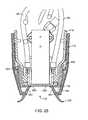
- FIG. 1illustrates a physician holding an applicator and a patient positioned to receive treatment.
- FIG. 2shows a perspective view of a tissue interface module attached to an applicator.
- FIG. 3illustrates a perspective view of a tissue interface module detached from an applicator.
- FIG. 4shows an end view of a multifunction connector.
- FIG. 5illustrates an end view of a tissue interface module.
- FIG. 6is a top view of a tissue interface module.
- FIG. 7shows a top perspective view of a tissue interface module.
- FIG. 8illustrates a top perspective view of an embodiment of a tissue interface module.
- FIG. 9shows an exploded top perspective view of a tissue interface module.
- FIG. 10is an exploded top perspective view of an embodiment of a tissue interface module.
- FIG. 11shows a side cutaway view of a tissue interface module.
- FIG. 12illustrates a side cutaway perspective view of a tissue interface module.
- FIG. 13is a perspective end view of an inner insert assembly from a tissue interface module.
- FIG. 14is an exploded perspective side view of the inner insert assembly of FIG. 13 .
- FIG. 15shows an end view of an applicator without a tissue interface module attached.
- FIG. 16illustrates a cutaway view of a section of an applicator and a portion of tissue interface module.
- FIG. 17Ais a side cutaway view of a portion of an applicator and a portion of tissue interface module with a magnet in a first position
- FIG. 17Bis a side cutaway view of a portion of an applicator and a portion of tissue interface module with a magnet in a second position.
- FIG. 18illustrates a side cutaway view of a section of an applicator and a tissue interface module as tissue is pulled into a tissue acquisition chamber by applied vacuum.
- FIG. 19shows a side cutaway view of a section of an applicator and a tissue interface module showing an air path with vacuum applied.
- FIG. 20is a side cutaway perspective view of an applicator and a tissue interface module showing some of the internal components of the applicator, including vacuum conduits.
- FIG. 21illustrates a side cutaway perspective view of an applicator showing some of the internal components of the applicator.
- FIG. 22shows a side cutaway perspective view of an applicator with a tissue interface module attached to the applicator and showing a portion of magnetic drive components.
- FIG. 23shows a side cutaway view of a tissue interface module.
- FIG. 24illustrates a side cutaway perspective view of a tissue interface module.
- FIG. 25illustrates an end cutaway view of a section of an applicator and a portion of a tissue interface module.
- FIG. 26is a side cutaway view of a portion of the applicator and a portion of a tissue interface module.
- FIG. 27illustrates a side cutaway view of a section of an applicator and a tissue interface module as tissue is pulled into a tissue acquisition chamber by applied vacuum.
- FIG. 28shows a side cutaway view of a section of an applicator and a tissue interface module showing air paths with vacuum applied.
- FIG. 29shows a side cutaway view of a tissue interface module of another embodiment of the invention.
- FIG. 30shows a side cutaway view of a section of an applicator and a tissue interface module.
- FIG. 31is a side cutaway view of a portion of an applicator and a portion of a tissue interface module.
- FIG. 32shows a side cutaway view of a section of an applicator and a tissue interface module showing an air path with vacuum applied.
- FIG. 1illustrates a Physician treating a patient with energy delivery system 110 (which may be referred to herein as system 110 ).
- Energy delivery system 110may include a console 112 , applicator 114 and tissue interface module 116 .
- Console 112may be referred to herein as generator 112 .
- Applicator 114may be referred to herein as hand piece or handpiece 114 .
- Tissue interface module 116may also be referred to as consumable 116 , disposable 116 , tissue interface 116 , applicator tissue interface 116 , module 116 or bioTip 116 .
- Console 112may include a display 164 , power cord 108 , holster 120 and foot pedal switch 132 .
- Display 164may be used to show a graphical user interface to guide the physician through treatment steps, such graphical user interface may include, for example, a color map of treatment temperatures, a placement count indicator and a placement positioning arrow.
- Applicator 114may include cable assembly 134 and multifunction connector 136 .
- Energy delivery system 110may be configured to deliver energy to tissue, including skin tissue.
- energy delivery system 110is configured to deliver microwave energy to the skin of the patient to treat a condition of the skin, such as, for example, hyperhidrosis, excessive sweating, bromhidrosis, cellulite, fat, wrinkles, acne, unwanted hair or other dermatological conditions.
- applicator 114When system 110 is assembled, applicator 114 may be connected to console 112 via multifunction connector 136 .
- Console 112may be configured to generate energy (e.g., microwave energy) at a frequency of, for example, approximately 5.8 gigahertz.
- Console 112may be configured to generate energy (e.g., microwave energy) at a frequency of, for example, between approximately 5.3 gigahertz and 6.3 gigahertz or between approximately 5.0 gigahertz and 6.5 gigahertz.
- applicator 114may be connected to console 112 with, for example, a microwave cable, a tensile cord, a USB cable, coolant tubing and vacuum tubing.
- Applicator 114may also be connected to a tissue interface module 116 .
- a foot pedal switch 132may be connected to console 112 to control one or more of the functions of console 112 , including the transmission of energy to applicator 114 or, alternatively, switches or buttons on applicator 114 may be used to control console 112 .
- console 112may also include a vacuum source, a cooling fluid source, (e.g., a chiller), a cooling fluid pump, an amplifier, a microwave generator, and control circuitry. These features of console 112 are internal to the console and are used to generate vacuum pressure, cooling fluid and microwave energy which may be transmitted through multifunction connector 136 and cable assembly 134 to applicator 114 .
- a cooling fluid sourcee.g., a chiller
- cooling fluid pumpe.g., a cooling fluid pump
- amplifiere.g., a microwave generator
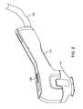
- FIG. 2shows a perspective view of applicator 114 with tissue interface module 116 attached to a distal end of applicator 114 .
- Cable assembly 134is shown extending from a proximal portion of applicator 114 .
- Applicator switch 130may be disposed on a surface of applicator 114 and may be used to control the application of treatment energy from applicator 114 .
- Applicator 114may also include main control circuitry adapted to control LED indicators, an antenna switch, and applicator switch 130 . In some embodiments, the main control circuitry may be designed to receive signals indicative of the direct or reflected power measured at each antenna in applicator 114 .
- FIG. 3shows a perspective view of applicator 114 with tissue interface module 116 detached from applicator 114 . Removal of tissue interface module 116 reveals electrical contacts 119 , which are configured to engage electrical contacts 160 (electrical contacts 160 may be formed by conductive traces on a suitable substrate) and printed circuit board 162 . Electrical contacts 160 and traces on printed circuit board 162 may be positioned on one or both sides of tissue interface module 116 . Electrical contacts 160 and associated circuitry may be used to, for example, detect the presence of tissue interface module 116 as it is being positioned on applicator 114 or to detect proper alignment of tissue interface module 116 when tissue interface module 116 is properly attached to applicator 114 .
- a security chipmay also be included on printed circuit board 162 , along with electrostatic discharge (ESD) protection such as, for example, an ESD diode.
- An integrated circuit 163(see FIGS. 8-10 ) may also be included to, for example, assist in detecting the presence and/or proper alignment of tissue interface module 116 .
- printed circuit board 162 and integrated circuit 163may be used to detect re-use of a previously used tissue interface module 116 . Such information may be used to, for example, notify the user that a new tissue interface module should be used or prevent the re-use of a previously used tissue interface module, which may be contaminated with, for example, biological fluids from a previous patient.
- Applicator 114may further include applicator switch 130 .
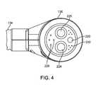
- FIG. 3also shows an end view of a multifunction connector 136 disposed at the proximal end of cable assembly 134 for attachment of applicator 114 to console 112 of FIG. 1 .
- FIG. 4shows an end view of multifunction connector 136 and cable assembly 134 .
- multifunction connector 136includes cooling fluid connector 224 , cooling fluid return connector 225 , microwave connector 220 , electronic connectors 222 and vacuum connectors 226 .
- Multifunction connector 136 and cable assembly 134provide a functional connection between console 112 and applicator 114 (see, for example FIG. 1 ), allowing applicator 114 to receive microwave energy, data, electrical energy, cooling fluid, and vacuum for treatment procedures and to transmit data back to console 112 .
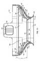
- FIG. 5illustrates an end view of tissue interface module 116 as viewed from the side of tissue interface module 116 that contacts tissue.
- Tissue interface module 116may include a tissue acquisition chamber 142 having a tissue interface surface 200 , a bio-barrier 152 , vacuum notches 214 , and skirt 206 .
- tissue interface surface 200may be, for example, a distal surface of bio-barrier 152 .
- skirt 206may not be used or may be modified to facilitate the acquisition of tissue.
- Tissue acquisition chamber 142may be sized to facilitate tissue acquisition in the treatment region of the patient.
- Tissue acquisition chamber 142may be sized to prevent elements of tissue interface module 116 from interfering with energy radiated from applicator 114 .
- tissue acquisition chamber 142may be sized to be approximately 1.54 inches long by 0.7 inches wide, having a depth of approximately 0.255 inches to 0.295 inches.
- Tissue acquisition chamber 142may be sized and configured such that the walls of tissue acquisition chamber 142 are outside of the outer edge of antenna array 124 (see, for example FIG. 21 ).
- Tissue acquisition chamber 142may include corners having a radius of approximately 0.1875 inches at a distal end thereof.
- Tissue acquisition chamber 142may include corners having a radius of approximately 0.29 inches at a distal end thereof. In some embodiments, these measurements may vary by, for example, up to plus or minus twenty percent.
- Tissue acquisition chamber 142is used to properly position tissue in tissue interface module 116 and to properly position such tissue adjacent the distal end of applicator 114 .
- Skirt 206may be made from, for example, a compliant medical grade plastic (e.g., a thermal plastic elastomer) such as, for example, urethane, or alternatively silicone, natural or synthetic rubber, elastomeric material, urethane foam with silicone, compliant plastic or a rubber seal coating.
- a suitable skirt 206may have a height of between 0.15′′ and 0.40′′ and more specifically, approximately 0.25′′ above tissue acquisition chamber 142 when skirt 206 is not compressed.
- skirt 206may have a durometer (hardness) of approximately 60 on the Shore A scale, or between 40 and 60, or between 20 and 80 on the Shore A scale.
- skirt 206may include inner walls having an average angle of approximately 53 degrees when not compressed.
- skirt 206may include inner walls having an average angle of approximately 49 degrees when not compressed. In some embodiments, these measurements may vary by, for example, up to plus or minus twenty percent. In some embodiments, skirt 206 may be clear or see-through to assist the physician in properly positioning applicator 114 with the tissue to be treated, by, for example, aligning skirt 206 with temporary markings on the patient's skin.
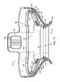
- FIG. 6is a top view of tissue interface module 116 from the proximal (non-treatment/applicator interface) side of tissue interface module 116 which is configured to attach to an applicator 114 , such as, for example, the applicator illustrated in FIGS. 1-3 .
- tissue interface module 116includes bio-barrier 152 , applicator chamber 118 , attachment mechanism 126 , vacuum channels 138 , attachment supports 127 , and gasket 158 .
- Gasket 158may be referred to as a consumable gasket 158 .
- Attachment mechanism 126may be, for example a magnet, a ferromagnetic plate or other ferromagnetic element and may be referred to as a latch plate or consumable latch plate.
- Vacuum channels 138may be positioned at a proximal end of a tissue chamber vacuum path.
- Applicator chamber 118is adapted to receive and connect to a distal end of applicator 114 .
- applicator 114may include, for example, a microwave antenna, a cooling element or cooling plate, and at least one vacuum inlet.
- Gasket 158may provide a substantially air tight (e.g., hermetic) seal against applicator 114 when a distal end of applicator 114 is positioned in applicator chamber 118 .
- gasket 158may allow a limited amount of air to pass, provided that such leaks do not adversely affect the vacuum balance described herein or otherwise adversely affect the function of the tissue interface module.
- a proximal end of gasket 158may form a sealing member.
- Gasket 158may have a hardness durometer of, for example, between 20 A and 80 A. Gasket 158 may also have a thickness of approximately 1/16th of an inch in some embodiments. In some embodiments, these measurements may vary by, for example, up to plus or minus twenty percent.
- the opening formed by gasket 158 at the proximal end of applicator chamber 118may act as a vacuum interface 504 (which may also be referred to as a vacuum outlet, vacuum outlet opening, vacuum channel or vacuum channel opening) when tissue interface module 116 is positioned on applicator 114 , air is channeled to flow out from applicator chamber 118 and into vacuum inlets 174 on applicator 114 .
- a vacuum interface 504which may also be referred to as a vacuum outlet, vacuum outlet opening, vacuum channel or vacuum channel opening
- Positioning vacuum interface 504 at a proximal end of tissue interface module 116 , in applicator chamber 118 ,may be particularly beneficial as it helps to maintain the pressure in applicator chamber 118 (P app ) at a pressure less than the pressure in the tissue acquisition chamber 142 (P tiss ), which helps to ensure that bio-barrier 152 will maintain its position against cooling plate 128 .
- This positionmay be maintained even in the presence of leaks, such as, for example, leaks at the interface between gasket engagement surface 500 and sealing surface 121 .
- This arrangementmay be particularly important in preventing the formation of bubbles, voids or deformities in the interface between bio-barrier 152 and applicator tissue treatment surface 502 (which may be, for example, the distal surface of cooling plate 128 ) thus protecting the patients skin from damage resulting from such bubbles, voids or deformities.
- Attachment mechanisms 126may be positioned on proximal side of tissue interface module 116 , such as, for example in applicator chamber 118 and be adapted to facilitate the attachment of module 116 to applicator 114 .
- attachment mechanism 126may include mechanical elements on applicator 114 and tissue interface module 116 .
- attachment mechanisms 126may include a metal or ferromagnetic plate configured to cooperate with a magnet or magnets on applicator 114 .
- attachment mechanisms 126form a completed magnetic circuit with elements of applicator 114 , including, for example, magnet 186 and magnetic extenders 179 (see, for example, FIGS. 17A and 17B ).
- Magnet 186 in cooperation with magnetic extenders 179may form at least a portion of a magnetic clamp adapted to engage and hold tissue interface module 116 in position during treatment of a patient.
- Magnet 186may be, for example, a diametrically magnetized neodymium cylindrical magnet.
- Attachment mechanism 126may be, for example, stainless steel plates, ferromagnetic plates, iron plates or steel plates. In some embodiments, attachment mechanisms 126 may be, for example, plates approximately 0.5 inches in width and 1.05 inches in length, with a thickness of approximately 0.63 inches. The size of these plates may, without substantial impact to performance, vary in other embodiments by, for example, plus or minus 20%.
- attachment mechanisms 126may rest upon attachment supports 127 , which keep attachment mechanisms 126 elevated above and prevent attachment mechanisms 126 from restricting the flow of air through vacuum channels 138 and a filter 154 (see, for example, FIG. 9 ).
- attachment supports 127are adapted to keep attachment mechanisms 126 raised approximately 0.010 inches (or, in some embodiments 0.080 inches) above filter(s) 154 , optimizing air flow through vacuum channels 138 without substantially increasing the size of tissue interface module 116 . In some embodiments, these measurements may vary by, for example, up to plus or minus twenty percent.
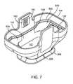
- FIG. 7is a top perspective view of tissue interface module 116 , also showing the proximal (non-treatment) side of tissue interface module 116 .
- FIG. 7shows applicator chamber 118 , which is adapted to receive and properly position applicator 114 with respect to bio-barrier 152 when tissue interface module is 116 attached to applicator 114 .
- applicator chamber 118is adapted to receive a distal end of applicator 114 , including, for example, a microwave antenna, a cooling element or cooling plate, and a vacuum inlet.
- Gasket 158may provide a seal between tissue interface module 116 and applicator 114 when tissue interface module 116 is attached to applicator 114 .
- Gasket 158may be held in place by attachment mechanisms 126 .
- Gasket 158may, in some embodiments, form at least a portion of vacuum interface 504 .
- Gasket 158may, in some embodiments, surround vacuum interface 504 .
- a gasket engagement surface 500which, in one embodiment of the invention may be located at a proximal end of gasket 158 , may be positioned such that gasket engagement surface 500 contacts sealing surface 121 on applicator 114 as tissue interface module 116 is attached to applicator 114 .
- Tissue interface module 116may be further designed to engage applicator 114 in a manner which causes gasket engagement surface 500 to deflect as it contacts sealing surface 121 .
- tissue interface module 116may further include electrical contacts 160 and printed circuit board 162 configured to, for example, detect the presence of tissue interface module 116 and/or proper alignment of tissue interface module 116 with applicator 114 .
- skirt 206which is configured to facilitate the engagement of tissue, and alignment marker 208 disposed on skirt 206 for aligning tissue interface module 116 with specific portions of the tissue to be treated.
- stamps or markingsincluding, for example, temporary tattoos may be used to mark patient tissue to appropriately place applicator 114 during treatment.
- Such stampsmay be sized to overlay an area to be treated, (e.g., an axilla).
- an axillaWhen used on an axilla, a physician may need to select different stamp sizes for different axilla sizes.
- Stampsare used to mark a number of different treatment points on a patient, including, for example, anesthesia injection sites. Physicians may use the marks created on the patients skin to properly place applicator 114 before and during treatment, using, for example alignment marker 208 on skirt 206 .
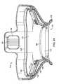
- FIG. 8is a top perspective view of an embodiment of a tissue interface module 116 .
- printed circuit board 162 , electrical contacts 160 , and integrated circuit 163are positioned on the same side(s) of tissue interface module 116 as attachment mechanism 126 .
- skirt 206 , alignment marker 208 , bio-barrier 152 , gasket 158 , and applicator chamber 118may also be seen in this alternative embodiment.
- FIG. 8also illustrates attachment mechanism 126 , gasket engagement surface 500 and vacuum interface 504 .
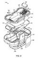
- FIG. 9is an exploded top perspective view of the tissue interface module 116 of FIGS. 5-7 .
- the tissue interface module 116may include an outer shell 193 and an inner insert 192 and may, in some embodiments also include a reflector 166 .
- Inner insert 192may include, for example, bio-barrier 152 , filters 154 , attachment mechanisms 126 , gasket 158 , vacuum channels 138 , attachment supports 127 and applicator chamber 118 .
- Outer shell 193may include, for example, electrical contacts 160 , printed circuit board 162 , integrated circuit 163 , insulating cover 168 , alignment marker 208 and skirt 206 .
- one or more filters 154may be positioned on either or both sides of bio-barrier 152 .
- Membranes or filters suitable for use as filters 154may include membranes which are permeable to air but substantially impermeable to biological fluids.
- Membranes or filters suitable for use as filters 154may include membranes which provide sufficient resistance to the flow of air to ensure a pressure differential between a first and a second side of filters 154 as air flows through filters 154 .
- filters 154allow air or gas but not fluid or tissue to pass (see, e.g., FIG. 5 ).
- a vacuum in applicator chamber 118pulls air through filters 154 , creating a vacuum in tissue acquisition chamber 142 to pull tissue positioned adjacent tissue acquisition chamber 142 into tissue acquisition chamber 142 and position that tissue against bio-barrier 152 and tissue interface surface 200 .
- tissue interface module 116pulls tissue into tissue interface module 116 and positions that tissue for treatment by applicator 114 .
- reflector 166may optionally be positioned between inner insert 192 and outer shell 193 , or integrated into inner insert 192 , outer shell 193 , or both.
- Reflector 166may include an electrically conductive mesh with openings of a predetermined size.
- reflector 166is configured to isolate stray electromagnetic fields and reflect stray electromagnetic energy back into applicator 114 .
- reflector 166is positioned so as to be electrically isolated from applicator 114 and electrically isolated from tissue positioned in tissue acquisition chamber 142 .
- Reflector 166may be sized and configured to surround at least a portion of and preferably most or all of tissue interface surface 200 when tissue interface module 116 is positioned on applicator 114 .
- Reflector 166may be sized and configured to surround at least a portion of and preferably most or all of distal surface of cooling plate 128 .
- reflector 166may include a metallic mesh material of wire having a diameter of approximately 0.008 inches with wires arranged in a mesh of approximately 30 by 30 wires per inch.
- reflector 166may include a metallic mesh having wires arranged in a mesh of approximately 100 by 100 exch. In some embodiments, these measurements may vary by, for example, up to plus or minus twenty percent.
- FIG. 10is an exploded top perspective view of tissue interface module 116 of FIG. 8 .
- tissue interface module 116may include an outer shell 193 and an inner insert 192 .
- Inner insert 192may include bio-barrier 152 , filter(s) 154 , attachment mechanisms 126 , gasket 158 , vacuum channels 138 , attachment supports 127 , applicator chamber 118 , electrical contacts 160 , printed circuit board 162 , integrated circuit 163 , tab member 146 , and latch openings 147 .
- Outer shell 193may include alignment marker 208 and skirt 206 .
- Reflector 166may optionally be positioned between inner insert 192 and outer shell 193 , or integrated into inner insert 192 , outer shell 193 , or both. The embodiments described herein are particularly advantageous because of the improvements they provide in manufacturability, quality, cost and manufacturing time.
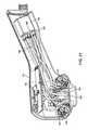
- FIG. 11illustrates a side cutaway view of a tissue interface module 116
- FIG. 12shows a side cutaway perspective view of tissue interface module 116
- the tissue interface module illustrated in FIGS. 11 and 12may include many of the features described herein, including tissue acquisition chamber 142 , bio-barrier 152 , filters 154 , applicator chamber 118 , electrical contacts 160 , printed circuit board 162 , attachment mechanism 126 , gasket 158 , gasket engagement surface 500 , inner insert 192 , outer shell 193 , reflector 166 , skirt 206 , acquisition chamber opening 143 , vacuum notches 214 (not shown in FIG. 12 ) and tissue interface surface 200 (not shown in FIG. 12 ).
- Attachment mechanisms 126include engagement surface 125 , which is configured to engage with cooperative elements on applicator 114 of FIGS. 2 and 3 (e.g., via magnetic attachment).
- engagement surface 125may form an angle X with a plane formed by bio-barrier 152 .
- Angle Xmay also be measured as the angle between engagement surface 125 and a plane through or parallel to applicator treatment surface 502 when tissue interface module 116 is positioned on applicator 114 (see, for example, the position of applicator treatment surface 502 FIG. 17A )
- tissue interface module 116may further include fluid traps 156 integrated into tissue interface module 116 .
- Fluid trap 156may also be referred to as a vacuum trap, vacuum reservoir or integrated fluid trap). Fluid traps 156 may be configured to, for example, trap contaminants such as tissue, bodily fluids or lubricants before such contaminants reach filter 154 .
- tissue interface module 116may include at least one expandable aperture 170 (also referred to as a variable flow restrictor or expandable channel) between tissue acquisition chamber 142 and fluid traps 156 .
- Fluid traps 156may be configured to, for example, collect blood, sweat, and any other bodily fluids or tissue that may collect within tissue interface module 116 during treatment. Fluid traps 156 may further collect liquids or jells, such as, for example, K-Y jelly, used to facilitate acquisition of tissue. By collecting bodily fluids or tissues in fluid traps 156 , tissue interface module 116 keeps filters 154 clear from obstructions that would otherwise interfere with the flow of air through such filters and might interfere with treatment or render treatment impossible. Thus, filters 154 are disposed between, and communicating with, both applicator chamber 118 and tissue acquisition chamber 142 . As described above, filters 154 may include openings configured to permit air or gas to pass but prevent liquid from passing through filters 154 . In one embodiment, applicator chamber 118 is able to communicate with tissue acquisition chamber 142 via filters 154 and vacuum channels 138 . Tissue interface module 116 may further include vacuum interface 504 .
- Expandable aperture 170may be included at a proximal end of tissue acquisition chamber 142 , and expandable aperture 170 may include, for example, a gap at top of tissue acquisition chamber 142 between a bio-barrier 152 and an interior rim of tissue acquisition chamber 142 . Vacuum notches 214 may be included in tissue acquisition chamber 142 proximal to the gap to enhance vacuum acquisition.
- one wall(such as, for example, the wall formed by bio-barrier 152 ) of expandable aperture 170 may be flexible to increase in size and increase airflow when vacuum is applied.
- a tissue treatment surface 200 of applicator 114may act to restrict the width of the aperture as it expands.
- a suitable expandable aperture 170may be sized to allow air to pass into a vacuum path while preventing tissue from blocking such vacuum path.
- FIG. 13illustrates a perspective end view of inner insert 192 , showing tissue interface surface 200 , bio-barrier 152 , filters 154 , and gasket 158 .
- This view of inner insert 192shows the portions of filters 154 which interface with and help form fluid traps 156 (see, e.g., FIGS. 11-12 ).
- tissue interface module 116positioned on applicator 114 and tissue positioned adjacent acquisition chamber opening 143
- all airflow exchange between applicator chamber 118 and tissue acquisition chamber 142flows through the interior of tissue interface module 116 .
- filters 154may be positioned on applicator 114 and tissue positioned adjacent acquisition chamber opening 143 .
- Maximizing the surface area of filters 154may increase vacuum performance and provide redundancy in case one of filters 154 becomes clogged with, for example, biological tissue, lubricants or bodily fluids.
- filters 154may occupy approximately the same surface area as bio-barrier 152 .
- a functional portion of bio-barrier 152may occupy approximately 60% (in some embodiments 50-70%), of the functional surface area of bio-barrier 152 , and a functional portion of filters 154 may occupy the remaining 30-50% of the total bio-barrier functional surface area.
- the functional areamay be the area of bio-barrier 152 which comes into contact with the distal side of cooling plate 128 .
- the functional areamay be the area of filter 154 through which air travels as air is pulled from tissue acquisition chamber 142 into applicator chamber 118 .
- a combined bio-barrier, including bio-barrier 152 and filters 154may include a functional area which is approximately fifty to seventy percent composed of bio-barrier 152 and approximately thirty to fifty percent composed of filters 154 .
- FIG. 14is an exploded perspective side view of inner insert 192 , revealing vacuum channels 138 and attachment supports 127 behind filters 154 .
- vacuum channels 138allow for airflow under attachment mechanisms 126 (see, e.g., FIG. 6 ) and through filters 154 , to allow for vacuum communication between applicator chamber 118 (see, e.g., FIG. 6 ) and tissue acquisition chamber 142 (see, e.g., FIG. 5 ) of tissue interface module 116 (see, e.g., FIG. 2 ).
- Inner insert 192further includes bio-barrier 152 and gasket 158 .
- FIG. 15shows an end view of applicator 114 without tissue interface module 116 (see, e.g., FIG. 2 ) attached.
- Applicator 114may include electrical contacts 119 for electrical coupling with electrical contacts 160 and printed circuit board 162 (see, e.g., FIG. 7 ) of tissue interface module 116 .
- Applicator 114may further include cooling plate 128 , applicator vacuum inlets 174 , applicator tissue treatment surface 502 , aesthetic features 175 and applicator engagement surface 178 .
- Applicator engagement surfaces 178are configured to engage attachment mechanisms 126 of tissue interface module 116 .
- Applicator engagement surface 178may include a first applicator engagement surface 178 A positioned at a distal end of a first magnetic extender 179 (see FIG. 17A ) and a second applicator engagement surface 178 B positioned at a distal end of a second magnetic extender 179 .
- Applicator vacuum inlets 174are coupled to a vacuum source in console 112 .
- tissue interface module 116is attached to applicator 114 (see e.g., FIG. 15 )
- applicator vacuum inlets 174are configured be positioned in applicator chamber 118 (see, e.g., FIG.
- Cooling plate 128 of applicator 114may include an alumina or other metal frame surrounding the back side of cooling plate 128 to add structural strength to cooling plate 128 , a plurality (e.g., four) of threaded rods may be bonded to the alumina frame to cooling plate 128 to a waveguide holder (not shown).
- cooling plate 128may comprise a ceramic material having approximately 94 to 99 percent alumina and 1 to 6 percent other material.
- Cooling plate 128may further include one or more thermocouple traces (of, for example, copper and constantan). These thermocouples may be arranged to detect a temperature of cooling plate 128 , a temperature of the surface of the tissue to be treated or a temperature of the interface.
- Such tracesmay be routed in side by side pairs to, for example, reduce the effect of noise on the output of such thermocouples. Such traces may be aligned to be perpendicular to the e-field emitted from the applicator to prevent the thermocouple traces from disrupting the e-field.
- FIG. 16shows a side cutaway view of a section of applicator 114 and a portion of tissue interface module 116 , including gasket 158 , attached to applicator 114 .
- the side angleshows how skirt 206 and tissue interface surface 200 form at least a portion of tissue acquisition chamber 142 .
- a portion of a vacuum flow path according to an embodimentmay also be seen in FIG. 16 , including, for example, tissue acquisition chamber 142 , expandable aperture 170 , and fluid trap 156 .
- a vacuum path according to an embodimentmay further include vacuum interface 504 .
- coolant conduits 185 of applicator 114which supply cooling fluid to cool applicator cooling plate 128 .
- Coolant conduits 185may include antimicrobial fittings and tubing using, for example, natural silver ion implanted antimicrobial tubing manufactured by Eldon James such as, for example FlexeleneTM. Such fittings and tubing may provide protection against microbial colonization (e.g., bacteria, mildew, mold and fungi). The tubing for conduits 185 may also be adapted to provide protection against microbial colonization without impacting, reducing or modifying the microwave characteristics (e.g., loss characteristics) of cooling fluid passing through such antimicrobial fittings and tubing.
- microbial colonizatione.g., bacteria, mildew, mold and fungi
- the tubing for conduits 185may also be adapted to provide protection against microbial colonization without impacting, reducing or modifying the microwave characteristics (e.g., loss characteristics) of cooling fluid passing through such antimicrobial fittings and tubing.
- FIGS. 17A-17Bare side cutaway views of a portion of applicator 114 and a portion of tissue interface module 116 attached to applicator 114 .
- applicator 114includes magnet 186 which may be rotatable or otherwise movable and may be configured to complete a magnetic circuit between magnetic extenders 179 and attachment mechanism 126 to attach tissue interface module 116 to applicator 114 .
- Applicator 114further includes antenna array 124 . Completing the magnetic circuit between magnetic extenders 179 and attachment mechanism 126 magnetically couples attachment mechanism 126 on tissue interface module 116 to magnetic extenders 179 on applicator 114 .
- Magnet 186may be coupled to a rotation mechanism such as a direct current gear motor or an RC servomotor, so as to rotate magnet 186 within magnetic extenders 179 between a position which results in an incomplete magnetic circuit and a position which results in a completed magnetic circuit.
- a rotation mechanismsuch as a direct current gear motor or an RC servomotor
- FIG. 17Athe “N” and “S” poles of magnet 186 are shown in the vertical position, resulting in an incomplete magnetic circuit by not completing the magnetic circuit with magnetic extenders 179 and attachment mechanism 126 .
- the magnetic circuitis incomplete, there is little or no magnetic attraction between attachment mechanism 126 and magnetic extenders 179 , facilitating removal of tissue interface module 116 from applicator 114 .
- FIG. 17Athe “N” and “S” poles of magnet 186 are shown in the vertical position, resulting in an incomplete magnetic circuit by not completing the magnetic circuit with magnetic extenders 179 and attachment mechanism 126 .
- a stopmay be implemented using a hall-effect position sensor or a hard stop.
- magnet 186may be positioned to partially complete the magnetic circuit prior to or as tissue interface module 116 is attached to applicator 114 to facilitate proper seating of tissue interface module 116 . Once tissue interface module 116 is properly seated on applicator 114 , magnet 186 may be positioned to fully close the magnetic circuit, holding tissue interface module 116 in place.
- tissue interface module 116includes gasket 158 , expandable aperture 170 , fluid trap 156 , tissue interface surface 200 , skirt 206 , tissue acquisition chamber 142 , bio-barrier 152 , filter 154 , outer shell 193 , reflector 166 , and attachment mechanisms 126 .
- a sealing surface 121(which may also be referred to as a gasket contact surface) of applicator 114 may be angled to receive gasket 158 from tissue interface module 116 .
- placing sealing surface 121 at an anglecauses gasket 158 to bend when tissue interface module 116 is attached to applicator 114 , improving the sealing characteristics by maximizing the contact surface between gasket 158 and sealing surface 121 and reducing the force required to attach the tissue interface module 116 to the applicator 114 .
- cooling plate 128is illustrated in FIG. 1 .
- applicator 114includes magnetic extenders 179 , magnet 186 , sealing surface 121 and cooling plate 128 .
- Tissue interface module 116includes gasket 158 , expandable aperture 170 , fluid trap 156 , skirt 206 , tissue acquisition chamber 142 , bio-barrier 152 , filter 154 , outer shell 193 , reflector 166 , attachment mechanism 126 and tissue interface surface 200 . Also illustrated is vacuum interface 504 .
- Tissue(including epidermis 410 , dermis 412 , dermal-hypodermal interface 414 , hypodermis 416 and muscle 418 ) is shown positioned partially within tissue acquisition chamber 142 .
- tissue acquisition chamber 142As tissue is pulled into tissue acquisition chamber 142 it moves towards tissue interface surface 200 and bio-barrier 152 . Pulling tissue into tissue acquisition chamber 142 may also provide a benefit of moving structures in the dermis and hypodermis away from deeper structures such as, for example, muscles and nerves.
- Vacuum pressure applied by applicator 114 to applicator chamber 118 of tissue interface module 116may be adapted to localize and stabilize tissue located in tissue acquisition chamber 142 .
- the vacuum pressureis also adapted to hold tissue positioned in tissue acquisition chamber 142 against tissue interface surface 200 and bio-barrier 152 .
- vacuum in tissue acquisition chamber 142pulls bio-barrier 152 into contact with cooling plate 128 , so as to ensure the efficient transfer of cooling energy to the epidermis 410 and underlying tissue during application of microwave energy.
- the vacuumis configured to have a flow rate of approximately 13.7 Standard Fluid Liters Per Minute during tissue acquisition which flow rate may, in some embodiments, vary by up to plus or minus twenty percent.
- the vertical distance 90 from gasket engagement surface 500(which in one embodiment may be the top of gasket 158 ) to a first connection point 590 on engagement surface 125 of FIGS. 11-12 of the uppermost portion of attachment mechanism 126 is approximately 0.15′′.
- the vertical distance 92 from gasket engagement surface 500 to a second connection point 592 on engagement surface 125 of the portion of attachment mechanism 126 that intersects the inside of the left magnetic extender 179is approximately 0.22′′.
- the vertical distance 94 from gasket engagement surface 500 to a third connection point 594 on engagement surface 125 of the portion of attachment mechanism 126 that intersects the inside of the right magnetic extender 179is approximately 0.27′′.
- the vertical distance 96 from gasket engagement surface 500 to a fourth connection point 596 on at the lower portion of engagement surface 125 of attachment mechanism 126is approximately 0.34′′. In some embodiments these measurements may vary by, for example, up to ⁇ 0.01′′. In some embodiments, these measurements may vary by ⁇ 0.05′′.
- the angle of engagement surface 125 of attachment mechanism 126may be identical or substantially identical (in one embodiment, within, for example, five degrees) to the angle of applicator engagement surface 178 at a distal end of magnetic extenders 179 to provide a flush fit between the extenders and the attachment mechanism 126 when the tissue interface module 116 is attached to the applicator 114 .
- the angle of applicator engagement surfaces 178may be arranged to be parallel or substantially parallel (in one embodiment within, for example, up to five degrees of parallel) to engagement surfaces 125 of attachment mechanism 126 to provide a flush fit between the extenders and the attachment mechanism 126 when tissue interface module 116 is attached to the applicator 114 .
- engagement surface 125may be sized and arranged to maximize the portion of engagement surface 125 contacted by applicator engagement surface 178 .
- a first portion of engagement surface 125is arranged to contact a first applicator engagement surface 178 A and a second portion of engagement surface 125 may be sized and arranged to contact a second applicator engagement surface 178 B.
- engagement surface 125may be sized and arranged to form a ferromagnetic bridge between applicator engagement surface 178 A and 178 B when tissue interface module 116 is positioned on applicator 114 . In one embodiment of the invention engagement surface 125 may be sized and arranged to form a closed magnetic circuit with applicator engagement surface 178 A and 178 B when tissue interface module 116 is positioned on applicator 114 .
- expandable aperture 170may be configured to expand when vacuum is applied by an applicator 114 to applicator chamber 118 and to tissue acquisition chamber 142 with tissue interface module 116 attached to applicator 114 .
- the application of vacuum to tissue interface module 116 at vacuum interface 504pulls bio-barrier 152 inwards towards cooling plate 128 of applicator 114 , which increases the size of expandable aperture 170 .
- FIGS. 17A and 17Billustrate embodiments of the invention wherein bio-barrier 152 is in its un-flexed state and expandable aperture 170 is at its minimum width. In FIG.
- expandable aperture 170has been opened to its maximum width by the application of vacuum pressure to applicator chamber 118 , which pulls bio-barrier 152 against applicator tissue treatment surface 502 (see, e.g., FIG. 15 ), which, in one embodiment may be cooling plate 128 .
- applicator tissue treatment surface 502see, e.g., FIG. 15
- FIG. 15which, in one embodiment may be cooling plate 128 .
- tissueis pulled into and air is pulled out of tissue acquisition chamber 142 a small vacuum pressure differential is maintained by the drop in pressure across filter 154 resulting from air flowing through filter 154 such that the pressure in applicator chamber 118 is less than the pressure in tissue acquisition chamber 142 .
- This pressure differentialmay be used to, for example, maintain the position of bio-barrier 152 against cooling plate 128 during the acquisition of tissue.
- This pressure differentialmay further be used to ensure that bio-barrier 152 is positioned against cooling plate 128 prior to tissue contacting tissue interface surface 200 . This pressure differential may further be used to ensure that bio-barrier 152 is positioned against cooling plate 128 without bubbles, voids or deformities. This pressure differential may further be used to ensure that tissue being pulled into tissue acquisition chamber 142 does not move or deform bio-barrier 152 . Once the air is removed from tissue acquisition chamber 142 and replaced by tissue, air will no longer flow through filter 154 into applicator chamber 118 and the pressure in the two chambers will be balanced or substantially balanced (e.g., having a pressure differential of less than approximately 4 pounds per square inch).
- tissue pressing against tissue interface surface 200may be used to maintain position of bio-barrier 152 against cooling plate 128 , preventing, for example, the formation of voids, bubbles or deformities which could result in hot spots.
- applicator 114may be positioned in applicator chamber 118 in a manner wherein cooling plate 128 , or some other feature of tissue interface module 116 , contacts bio-barrier 152 prior to the application of vacuum, preventing expandable aperture 170 from opening when vacuum is applied.
- FIG. 19is a side cutaway view of applicator 114 and tissue interface module 116 of FIGS. 17-18 showing air paths A and B through tissue interface module 116 with vacuum applied.
- Vacuummay be applied by applicator 114 directly to applicator chamber 118 (through, for example, vacuum interface 504 ) of tissue interface module 116 to create vacuum within applicator chamber 118 , as well as within tissue acquisition chamber 142 .
- a first vacuum flow path Aextends from tissue acquisition chamber 142 , through expandable aperture 170 , into fluid trap 156 , through filter(s) 154 , through vacuum channels 138 and into applicator chamber 118 and into applicator 114 .
- Second vacuum flow path Bshows vacuum being pulled directly from applicator chamber 118 .
- tissue positioned at acquisition chamber opening 143may be pulled into tissue acquisition chamber 142 , as shown in FIG. 18 .
- Tissue, lubricants or bodily fluids, such as blood or sweatmay collect in fluid trap 156 and those not captured in fluid trap 156 may be stopped by filter 154 . Since filters 154 are permeable to air or gas but not to liquid, vacuum may be pulled through filters 154 without contaminating applicator chamber 118 or the surface of applicator 114 .
- the vacuum air paths A and Bmay be used to equalize or substantially equalize pressure (in some embodiments equalize to, for example, within four pounds per square inch) on both sides of filter 154 (i.e., the pressure in tissue acquisition chamber 142 and applicator chamber 118 ).
- the resistance to airflowis higher in vacuum path A than in vacuum path B, ensuring that, as long as air is flowing in vacuum path A, the air pressure in applicator chamber 118 will be lower than the air pressure in tissue acquisition chamber 142 .
- filter 154provides resistance to the flow of air in vacuum path A, ensuring that, as long as air is flowing in vacuum path A, the air pressure in applicator chamber 118 will be lower than the air pressure in tissue acquisition chamber 142 .
- the vacuum flow pathis completely internal to tissue interface module 116 and applicator 114 , originating in applicator 114 itself, and pulling vacuum from applicator chamber 118 , through filters 154 , through fluid traps 156 , through expandable aperture 170 , and finally through tissue acquisition chamber 142 to engage tissue in tissue acquisition chamber 142 .
- the vacuum flow pathhooks up directly from applicator chamber 118 of tissue interface module 116 to vacuum inlets 174 of applicator 114 , without requiring an external attachment from tissue interface module 116 to applicator 114 or to a separate vacuum source.
- the vacuum pathmay include at least one portion having a gap width of approximately 0.036 inches.
- the minimum gap width at any point along vacuum path Amay be approximately 0.036 inches. In one embodiment, the smallest dimension in a cross section of the airflow pathway along vacuum path A will be approximately 0.036 inches. In some embodiments, these measurements may vary by, for example, up to plus or minus twenty percent. In one embodiment of the invention, the smallest cross section in vacuum path A will be the cross section formed on a first side by expandable aperture 170 .
- tissue interface module 116When using tissue interface module 116 vacuum may be achieved and maintained when tissue interface module 116 is attached to applicator 114 , forming a seal between tissue interface module 116 and applicator 114 , and tissue is engaged by tissue acquisition chamber 142 (as shown in FIG. 18 ) forming a seal between the engaged tissue and skirt 206 .
- Tissue interface module 116may include one or more vacuum balance pathways designed therein.
- One vacuum balance pathmay include tissue acquisition chamber 142 , fluid trap 156 and at least one filter 154 adapted to allow air to pass without allowing other fluids to pass.
- An expandable aperture 170 forming an entrance to fluid trap 156may also be included and may be flexible to allow the entrance to fluid trap 156 to open, creating a wider gap when vacuum is applied.
- a reflector 166may further be included in the vacuum path as, for example, a portion of fluid trap 156 .
- tissue interface module 116when using tissue interface module 116 , and particularly as tissue is pulled into tissue acquisition chamber 142 , a balance or approximate balance between air pressure in applicator chamber 118 and tissue acquisition chamber 142 may be maintained.
- the air pressure in applicator chamber 118may be, for at least a period of time, at a pressure below the air pressure in tissue acquisition chamber 142 .
- tissue interface module 116when using tissue interface module 116 , and particularly as tissue is pulled into tissue acquisition chamber 142 , a balance may be maintained wherein air pressure in applicator chamber 118 is slightly lower than an air pressure in tissue acquisition chamber 142 .
- An applicator chamber 118may be designed and configured to allow applicator 114 , when inserted into applicator chamber 118 to form an airtight seal around applicator chamber 118 (e.g., with a gasket 158 ) and to position a distal end of applicator 114 (e.g., cooling plate 128 application surface) within a predetermined distance (e.g., approximately 0.026 inches) of bio-barrier 152 .
- a first balance path(e.g., Path B in FIG. 19 ) may be created by the direct interconnection between applicator 114 and applicator chamber 118 such that air pulled from applicator chamber 118 travels directly into applicator 114 through vacuum inlets 174 .
- a second balance path(e.g., Path A in FIG. 19 ) may be created by the indirect interconnection between applicator 114 and tissue acquisition chamber 142 , wherein air from tissue acquisition chamber 142 must pass through at least filter 154 before being pulled into applicator 114 through vacuum inlets 174 .
- First and second balance pathsmay combine in applicator chamber 118 .
- air being evacuated from tissue acquisition chamber 142 , through filter 154may flow past one or more magnetic plates forming attach mechanism 126 .
- applicator 114may further include antenna array 124 , magnetic extenders 179 , and tissue interface surface 200 .
- tissue interface module 116may further include engagement surface 125 , outer shell 193 , skirt 206 and gasket engagement surface 500 .
- FIG. 20shows a side cutaway view of a portion of the distal end of applicator 114 , showing some of the internal components of applicator 114 , including applicator logic circuits 181 , microwave feed cables 182 , coolant conduits 185 , vacuum conduits 184 , antenna array 124 , sealing surface 121 and magnetic drive 187 .
- Magnetic drive 187may include, for example, DC motors to position magnets 186 (e.g., by rotating magnets 186 ) and hall-effect sensors to sense the position of magnets 186 .
- FIG. 20also includes a cutaway view of tissue interface module 116 , including applicator chamber 118 , bio-barrier 152 , vacuum interface 504 , filter 154 and tissue acquisition chamber 142 . As shown, applicator chamber 118 of tissue interface module 116 is adapted and configured to receive the distal end of applicator 114 , positioning antenna array 124 , cooling plate 128 and vacuum inlets 174 in applicator chamber 118
- FIG. 21is a side cutaway perspective view of applicator 114 showing some of the internal components of applicator 114 , including applicator logic circuits 181 , microwave feed cables 182 , coolant conduits 185 , vacuum conduits 184 , antenna array 124 , microwave switch 180 and magnetic drive 187 .
- FIG. 22is a side cutaway perspective view of applicator 114 with tissue interface module 116 attached showing a portion of magnetic drive components, including magnetic drive 187 .
- Magnetic drive 187may be used to open a magnetic circuit by, for example, positioning magnet 186 in the position illustrated in FIG. 17A with respect to extenders 179 .
- Magnetic drive 187may be used to complete a magnetic circuit by, for example, positioning magnet 186 in the position illustrated in FIG. 17B with respect to extenders 179 .
- tissue interface module 116may be magnetically attached to applicator 114 .
- engagement surface 125forms an Angle X (see FIG. 11 ) of approximately 22.5 degrees from horizontal (e.g., from a plane through bio-barrier 152 when bio-barrier 152 is un-flexed) so as to couple to mating attachment points on applicator 114 , such as, for example, applicator engagement surfaces 178 at a distal end of magnetic extenders 179 .
- engagement surface 125forms an Angle X of between approximately 17.5 degrees and 27.5 degrees, or alternatively, an Angle X of between approximately 12.5 degrees and 32.5 degrees.
- Angle X of engagement surface 125may vary, up to and including 45 degrees or more, depending upon the angle chosen for the mating engagement surfaces on applicator 114 .
- applicator engagement surfaces 178 on applicator 114are designed to be parallel to engagement surface 125 when tissue interface module 116 is properly positioned on applicator 114 .
- Creating an engagement surface 125 which conforms to the mating surface (e.g., applicator engagement surface 178 ) on applicator 114may be important to ensure the maximum surface area of contact between engagement surface 125 and mating surfaces on applicator 114 . Ensuring maximum surface area contact may, for example, maximize the magnetic force applied to hold tissue interface module 116 in place and prevent tissue interface module 116 from shifting or falling off of applicator 114 during treatment.
- Applicator engagement surface 178may extend a predetermined distance from the outer surface of applicator 114 to ensure proper contact between applicator engagement surfaces 178 and engagement surface 125 and proper positioning of gasket engagement surface 500 of gasket 158 against sealing surface 121 . Maximizing the magnetic force will also provide optimum compression of gasket 158 when it is positioned against the outer surface of applicator 114 , preventing vacuum leaks which could cause tissue in tissue acquisition chamber 142 to shift or move during treatment or cause such tissue to lose contact with bio-barrier 152 and/or tissue interface surface 200 or to lose functional contact with applicator tissue treatment surface 502 and/or cooling plate 128 .
- Engagement surface 125may further be arranged to be parallel to or substantially parallel (within e.g., 10 degrees), for example, surfaces at a distal end of magnetic extenders 179 on applicator 114 .
- Engagement surface 125may further be arranged such that engagement surfaces 125 contact substantially all (e.g., eighty percent or more) of a distal end surface of magnetic extenders 179 on applicator 114 .
- Engagement surface 125may further be arranged to maximize the magnetic force exerted on attachment mechanism 126 by magnet 186 when magnet 186 is arranged to exert force on attachment mechanism 126 through magnetic extenders 179 .
- Engagement surface 125may be positioned to extend from applicator engagement surface 178 A to applicator engagement surface 178 B, thus closing the gap between applicator engagement surface 178 A and applicator engagement surface 178 B and creating a closed magnetic circuit.
- Bio-barrier 152(which may also be referred to as a first bio-barrier, a membrane or first membrane) may be configured and/or made of a material which is substantially impermeable to both liquids (e.g., bodily fluids such as blood or sweat) and may also be impermeable to gases (e.g., air).
- substantially impermeablemay mean that a barrier is, for example, permeable enough to permit some fluid and/or air to pass but not permeable enough to effect the functionality of the barrier or of tissue interface module 116 .
- substantially impermeablemay mean that a barrier is, for example, permeable enough to permit some fluid and/or air to pass but not permeable enough to allow biological fluids, such as blood or sweat, to pass.
- bio-barrier 152may be constructed of impermeable materials, such as, for example, polyurethane film and may have a thickness of for example, 0.0005 inches or 0.00085 inches. In some embodiments, bio-barrier 152 may have a thickness of between approximately 0.00075 inches and 0.001 inches.
- Bio-barrier 152is further designed to be sufficiently flexible to conform to applicator tissue treatment surface 502 (which may also be referred to as a tissue surface, treatment surface or distal surface of a cooling plate), where applicator tissue treatment surface 502 is located at a distal end of applicator 114 (see, for example, FIG. 15 ) without creating bubbles, voids or deformities.
- bio-barrier 152 and filter 154(which may also be referred to as a second bio-barrier, a permeable bio-barrier or a semi-permeable bio-barrier) may work together to comprise a multifunctional bio-barrier.
- filter 154may comprise a first filter and a second filter. In embodiments of the invention, filter 154 may comprise a first filter and a second filter wherein the first and second filters are positioned on opposite sides of bio-barrier 152 . In embodiments of the invention a multifunction bio-barrier, comprising, for example, a first impermeable membrane and a second air-permeable membrane, may be used to balance vacuum pressure in an applicator chamber 118 with vacuum pressure in a tissue acquisition chamber 142 when air is drawn, by, for example, the attachment of vacuum ports to applicator chamber 118 .
- a multifunction bio-barriercomprising, for example, a first impermeable membrane and a second air-permeable membrane, may be used in a vacuum pathway between applicator chamber 118 and a tissue acquisition chamber 142 such that establishing a vacuum in applicator chamber 118 pulls air from tissue acquisition chamber 142 through the multifunction bio-barrier while preventing biological fluids from passing from tissue acquisition chamber 142 into applicator chamber 118 , preventing contamination of the distal end of the applicator 114 .
- Bio-barrier 152may be designed to have specific microwave and thermal characteristics.
- bio-barrier 152may be designed to have a loss tangent (tan( ⁇ )) of 0.1 or less, and more particularly, a loss tangent of approximately 0.0004.
- Bio-barrier 152may have a loss tangent (tan( ⁇ )) of less than one.
- bio-barrier 152may be made from a material having a lost tangent of one or less.
- bio-barrier 152may be designed to have an electrical conductivity suitable for use a in a microwave system, such as having an electrical conductivity ( ⁇ ) of between 0.0 and 0.2 siemens/meter.
- bio-barrier 152may be designed to have an electrical conductivity which is less than or equal to the transmission frequency in hertz (e.g., 5.8 GHz) multiplied by the real part of the permittivity of bio-barrier 152 .
- Bio-barrier 152may also be designed to have a thermal conductivity and be made from a material suitable for use in a microwave system, such as having a thermal conductivity of at least approximately 0.1 watts per meter Kelvin (0.1 W/mK), and desirably 0.1 to 0.6 W/mK, and most desirably 0.25 to 0.45 W/mK.
- bio-barrier 152may be designed to have a heat transfer coefficient which makes it suitable for efficiently removing heat from tissue adjacent to bio-barrier 152 , such as having a heat transfer coefficient of approximately 7874 W/m 2 K. In some embodiments, these measurements may vary by, for example, up to plus or minus twenty percent.
- bio-barrier 152may be designed to conform to applicator tissue treatment surface 502 , particularly when a vacuum is applied to applicator chamber 118 .
- bio-barrier 152may be configured to deflect at least 0.010 inches with a vacuum of, for example, approximately ⁇ 20 inches of mercury applied to applicator chamber 118 without tearing or deforming. In some embodiments, these measurements may vary by, for example, up to plus or minus twenty percent.
- Bio-barrier 152may be designed to deflect or stretch to cover applicator tissue treatment surface 502 without forming bubbles, voids or deformities as such bubbles, voids or deformities may perturb microwave energy passing through bio-barrier 152 .
- Such perturbationsmay, in certain circumstances, result in potential hot spots adjacent tissue interface surface 200 and/or between bio-barrier 152 and applicator tissue treatment surface 502 (see, for example, FIG. 15 ).
- a distal surface of tissue cooling plate 128forms at least a portion of applicator tissue treatment surface 502 of applicator 114 .
- Such bubbles, voids or deformitiesmay provide pockets of insulation (e.g., air) between the skin surface and cooling plate 128 , preventing cooling plate 128 from properly cooling the surface of the skin as energy is applied through bio-barrier 152 .
- tissue interface module 116When tissue interface module 116 is placed against tissue, such as, for example, the skin, skirt 206 may engage the tissue and form a sealed enclosure, wherein the enclosure includes the tissue, tissue acquisition chamber 142 , skirt 206 , and bio-barrier 152 . With tissue interface module 116 positioned on applicator 114 , vacuum may then be applied by pulling air through vacuum inlets 174 (also referred to as vacuum ports or vacuum inlet openings) at a distal end of applicator 114 (see, for example, FIG. 15 ) to pull tissue into tissue acquisition chamber 142 and up against tissue interface surface 200 , which, in some embodiments, may comprise a distal surface of bio-barrier 152 .
- vacuum inlets 174also referred to as vacuum ports or vacuum inlet openings
- tissue interface module 116may include, for example, four vacuum notches 214 . However, in other embodiments, more or fewer vacuum notches 214 may be included around bio-barrier 152 . Increasing the number of vacuum notches 214 and positioning the vacuum notches around a perimeter of bio-barrier 152 may improve vacuum performance in the tissue acquisition chamber 142 and provide vacuum redundancy in the event that one or more of vacuum notches 214 becomes clogged with blood, tissue, or other bodily fluids during treatment.
- filters 154may be made from hydrophobic material. In other embodiments, filters 154 may have a pore size which allows for passage of gas or air with a hydrophobicity that prevents the passage of liquids such as blood and sweat. In some embodiments, filters 154 may have a physical size and be made from a material having a pore size such that the overall opening facilitates the equalization of pressure across such filter 154 within approximately 0.25 seconds (with a range of between approximately 0.1 and 3 seconds) as tissue is drawn into tissue acquisition chamber 142 .
- filters 154may have a physical size and be made from a material having a pore size which restricts the flow of air sufficiently to create a pressure differential between the air pressure in applicator chamber 118 and the air pressure in tissue acquisition chamber 142 during the time when air is flowing through filter 154 .
- filters 154may act as air restrictors, restricting, but not eliminating the free flow of air between applicator chamber 118 and tissue acquisition chamber 142 .
- filters 154may be positioned such that air pressure in tissue acquisition chamber 142 is greater than air pressure in applicator chamber 118 during periods when air is being drawn from tissue acquisition chamber 142 through applicator chamber 118 , facilitating the positioning of a bio-barrier 152 against applicator tissue treatment surface 502 of applicator 114 . In some embodiments, filters 154 may be positioned such that a vacuum in tissue acquisition chamber 142 is less than a vacuum in applicator chamber 118 during periods when air is drawn from tissue acquisition chamber 142 and applicator chamber 118 , facilitating the positioning of a bio-barrier 152 against applicator tissue treatment surface 502 of applicator 114 .
- filters 154may have a flow rate of a predetermined value when vacuum is applied. In one embodiment, filters 154 may have pore sizes of approximately 0.45 um and a flow area of approximately 1.86 square inches. In some embodiments, these measurements may vary by, for example, up to plus or minus twenty percent. Filter 154 may be, for example, PTFE on a polyester backing, polyethylene film, nylon or other material meeting the criteria set forth above.
- tissue interface modules illustrated in FIGS. 23 to 32may include many of the features described herein with respect to prior described embodiments, including tissue interface module 116 , applicator 114 , vacuum channels 138 , tissue acquisition chamber 142 , filters 154 , applicator chamber 118 , electrical contacts 160 , printed circuit board 162 , attachment mechanism 126 , engagement surfaces 125 , gasket 158 , gasket engagement surface 500 , inner insert 192 , outer shell 193 , reflector 166 , fluid trap 156 , skirt 206 , acquisition chamber opening 143 and vacuum interface 504 but omit the flexible bio-barrier 152 shown in earlier embodiments.
- tissue interface module 116tissue interface module 116 , applicator 114 , vacuum channels 138 , tissue acquisition chamber 142 , filters 154 , applicator chamber 118 , electrical contacts 160 , printed circuit board 162 , attachment mechanism 126 , engagement surfaces 125 , gasket 158 , gasket engagement surface 500 , inner insert 192 , outer
- tissue acquisition chamber 142 and fluid trap 156may further include an intermediate gasket 600 (which may also be referred to as an intermediate sealing member) and one or more air passages 602 extending between tissue acquisition chamber 142 and fluid trap 156 .
- Embodiments of applicators illustrated in FIGS. 23 to 32may include many of the features described herein with respect to prior described embodiments, including cooling plate 128 , applicator vacuum inlets 174 , coolant conduits 185 , tissue interface surface 200 , magnetic extenders 179 , magnet 186 , sealing surface 121 and vacuum conduits 184 .
- Tissue interface surface 200may, in some embodiments of the invention comprise at least a portion of applicator tissue treatment surface 502 .
- applicator vacuum inlets 174are configured to be positioned in applicator chamber 118 (see, e.g., FIGS. 28 and 32 ) and to evacuate air from applicator chamber 118 through, for example, vacuum interface 504 , creating a vacuum in applicator chamber 118 .
- embodiments of the tissue interface modules illustrated in FIGS. 23-32provide a seal (see for example, intermediate gasket 600 ) between tissue interface module 116 and applicator 114 , thereby separating applicator chamber 118 from tissue acquisition chamber 142 .
- This sealprevents air from flowing directly from tissue acquisition chamber 142 to applicator chamber 118 , facilitating the flow of air through filter 154 and air passages 602 along air flow path A in FIGS. 28 and 32 when a vacuum is applied to applicator chamber 118 , through, for example, vacuum interface 504 .
- air extracted from applicator chamber 118will flow along path B as illustrated in FIGS. 28 and 32 .
- tissue acquisition chamber 142when the skirt 206 of tissue interface module 116 is placed against a patient's skin surface, the vacuum created in tissue acquisition chamber 142 in response to movement of air along these flow paths A and B will draw the patient's skin and underlying tissue (including epidermis 410 , dermis 412 , dermal-hypodermal interface 414 , hypodermis 416 and muscle 418 ) into tissue acquisition chamber 142 toward the applicator cooling plate 128 .
- filters 154may, in some embodiments be used to ensure that the air pressure in tissue acquisition chamber 142 is higher than the air pressure in applicator chamber 118 until the patient's tissue ceases moving into tissue acquisition chamber 142 , at which point the air pressures in the two chambers will equalize.
- tissue interface moduleillustrated in, for example, FIGS. 23 through 28
- intermediate sealin the form of, for example, intermediate gasket 600 may be positioned such that, when attached to applicator 114 gasket 600 forms an air tight or substantially air tight seal against a surface of cooling plate 128 .
- intermediate sealin the form of, for example, intermediate gasket 600 may be positioned such that, when attached to applicator 114 gasket 600 is adapted to form an air tight or substantially air tight seal against an outer surface of applicator 114 .
- air passages 602may be positioned outside of tissue acquisition chamber 142 to reduce or eliminate the potential for air passages 602 to be blocked by tissue in tissue acquisition chamber 142 .
- Some embodiments, such as, for example, those in FIG. 29may also include vacuum notches 214 to facilitate the flow of air from tissue acquisition chamber 142 around the distal end of applicator 114 (when tissue interface module 116 is positioned on applicator 114 ) and into air passages 602 .
- engagement surface 125may form an Angle Y between engagement surface 125 and a plane passing through gasket 600 .
- engagement surface 125may form an Angle Z between engagement surface 125 and a plane passing through gasket 600 .
- Angles Y and Zmay be measured between engagement surface 125 and a plane running through or parallel to the distal surface of cooling plate 128 when tissue interface module 116 is positioned on applicator 114 .
- Angles Y and Zmay be approximately 22.5 degrees.
- Angles Y and Zmay be between approximately 17.5 degrees and 27.5 degrees, or alternatively, between approximately 12.5 degrees and 32.5 degrees. In other embodiments, Angles Y and Z may vary, up to and including 45 degrees or more, depending upon the angle chosen for the mating engagement surfaces on applicator 114 .
- tissue interface module 116when a vacuum is applied to vacuum interface 504 at the proximal end of the tissue interface module 116 .
- tissue interface module 116With tissue interface module 116 positioned on applicator 114 and tissue engaged, as, for example, in FIG. 27 , air trapped in tissue acquisition chamber 142 may flow, through the air passage A, including air passages 602 , fluid trap 156 , through filter 154 and vacuum channels 138 , under attachment mechanism 126 , through applicator chamber 118 to vacuum interface 504 and into vacuum inlet 174 in applicator 114 .
- air passage Aincluding air passages 602 , fluid trap 156 , through filter 154 and vacuum channels 138 , under attachment mechanism 126 , through applicator chamber 118 to vacuum interface 504 and into vacuum inlet 174 in applicator 114 .
- airmay be prevented from bypassing filter 152 by the intermediate sealing member 600 .
- airmay be prevented from bypassing filter 152 by bio-barrier 152 .
- Air in applicator chamber 118flows along path B through vacuum interface 504 and into vacuum inlet 174 .
- tissue interface moduleWith the tissue interface module positioned on the applicator and no tissue engaged, air entering the tissue acquisition chamber flows into the tissue chamber, through the expandable aperture, into the vacuum trap, through the filter, under the engagement plate, through the applicator chamber to the vacuum interface and into the applicator. With the tissue interface module positioned on the applicator, and no tissue engaged, air in the applicator chamber flows through the applicator chamber to the vacuum interface and into the applicator.
- tissue acquisition chamberWith the distal end of the tissue interface module positioned against tissue, sealing the end of the tissue chamber from outside air, air in the tissue acquisition chamber is evacuated from the tissue acquisition chamber by flowing through the expandable channel, into the vacuum trap, through the filter, under the engagement plate, through the applicator chamber to the vacuum interface and into the applicator, creating a vacuum in the tissue acquisition chamber.
- the vacuum created in the tissue acquisition chamberpulls tissue into the tissue acquisition chamber, filling the tissue acquisition chamber.
- air in the applicator chamberflows through the applicator chamber to the vacuum interface and into the applicator, creating a vacuum in the applicator chamber.
- tissue engaged at the distal end of the tissue interface moduleair evacuated from the tissue acquisition chamber must pass through a first vacuum path which includes the tissue acquisition chamber, the expandable aperture, the vacuum trap, the filter, a space under the engagement plate, the applicator chamber and the vacuum interface.
- air evacuated from the applicator chambermust pass through a second vacuum path which includes the applicator chamber and the vacuum interface.
- Air passing through the vacuum interfacetravels two pathways. Air in the applicator chamber flows through a first, direct pathway from the applicator chamber to the vacuum interface. Air in the tissue acquisition chamber travels a second, indirect, pathway which passes through the filter.
- the second, indirect pathwaymay further include one or more of: an expandable aperture; a vacuum trap, an applicator chamber and a vacuum interface.
- the engagement and proper positioning of tissueis facilitated by positioning tissue at a distal end of a tissue acquisition chamber, forming a seal, pulling air from the tissue chamber though a pathway which includes in some embodiments a multifunction bio-barrier, the bio-barrier being composed of at least two parts.
- the first part of the bio-barriermay be substantially impermeable to air and fluids.
- the second part of the bio-barriermay be permeable to air but substantially impermeable to fluids.
- the first part of the multifunction bio-barriermay be a flexible bio-barrier which performs one or more of the following functions: preventing air from passing from the tissue acquisition chamber into the applicator chamber; preventing fluids from passing from the tissue acquisition chamber into the applicator chamber; diverting air being removed from the tissue chamber into a path which includes the second part of the multifunction bio-barrier; forming a substantially deformity free (e.g., no bubbles, voids or other deformities) seal against the distal end (e.g., cooling plate) of the applicator; forming at least one wall of an expandable aperture between the tissue acquisition chamber and the applicator chamber; and providing a pathway for energy and cooling to pass into tissue engaged in the tissue acquisition chamber.
- a substantially deformity freee.g., no bubbles, voids or other deformities
- the second part of the multi-function bio-barriermay be one or more hydrophobic filters which performs one or more of the following functions: providing a pathway for air leaving the tissue acquisition chamber to enter the applicator chamber; preventing fluids (e.g., bodily fluids or lubricants) from passing from the tissue acquisition chamber into the applicator chamber; restricting the flow of air between the tissue acquisition chamber and the applicator chamber; ensuring that, at least while air is flowing from the tissue acquisition chamber to the applicator chamber, the air pressure in the tissue acquisition chamber is lower than the air pressure in the applicator chamber.
- fluidse.g., bodily fluids or lubricants
- the presence of a vacuum imbalance with a higher pressure in the tissue acquisition chamber than in the applicator chamberforces the flexible bio-barrier against the distal end of the applicator and maintains the position of the flexible bio-barrier against the distal end of the applicator as tissue is drawn into the tissue acquisition chamber.
- the vacuum imbalancefurther assures that the flexible bio-barrier will sit against the distal end of the applicator without bubbles etc. until tissue fills the tissue acquisition chamber. Once the tissue acquisition chamber is filled, the presence of the tissue maintains the bio-barrier against the distal end of the applicator.
- establishing and maintaining a substantially discontinuity-free (e.g., bubble-free) interface between the flexible bio-barrier and the distal end of the applicatoris important for a number of reasons. It reduces the chances of a burn resulting from an air pocket. It enhances the transfer of cold energy from the cooling plate to the tissue. It eliminates the insulating effect of air trapped between the flexible bio-barrier and the cooling plate. It enhances the coupling of microwave energy from the applicator to the tissue. It reduces or eliminates discontinuities which might perturb the microwaves being radiated into the skin.
- the tissue interface modulefacilitates the efficient transfer of energy between the applicator and the tissue by ensuring that the flexible bio-barrier is pulled against the distal end of the applicator in a manner which minimizes discontinuities (e.g., bubbles) which could form between the distal end of the applicator and the flexible bio-barrier.
- discontinuitiese.g., bubbles
- the elimination of discontinuitiesis important because such discontinuities could: prevent the efficient cooling of the skin by insulating the skin under the discontinuity from the cooling plate; result in the creation of “hot spots” which might cause patient burns; change the “load” characteristics of the skin/cooling plate interface at the frequency of interest, thus reducing the efficiency of energy transfer and, potentially, the effectiveness of the treatment.
- the series of stepsmay include one or more of the following: positioning a tissue interface module at a distal end of an applicator; attaching the tissue interface module to the applicator by closing a magnetic circuit, channeling magnetic flux through an engagement mechanism on the tissue interface module; positioning the tissue interface module so that the distal end of the tissue interface module is in contact with tissue such as, for example, skin; evacuating air from an applicator chamber at a proximal end of the tissue interface module; evacuating air from a tissue acquisition chamber through the applicator chamber; creating a pressure differential such that the air pressure in the applicator chamber is, during the tissue acquisition period (the period during which tissue is being pulled into the acquisition chamber), lower than the air pressure in the tissue acquisition chamber; pulling air through a filter as the air passes from the tissue acquisition chamber into the applicator chamber; pulling a flexible bio-barrier against a distal side of a cooling plate positioned at the distal end of the applicator;
- the energy transmission path in the applicatormay include: an antenna; at least one field spreader; a fluid channel; and a cooling plate.
- the energy transmission path in the tissue interface modulemay include: a vacuum interface, an applicator chamber; a flexible bio-barrier and a tissue acquisition chamber. In this embodiment, the energy is radiated through the center of the vacuum interface.
- Applicatorengages by placing engagement plates positioned in the applicator chamber against parallel surfaces at the end of magnetic extenders on the applicator such that magnetic the engagement plates close a magnetic circuit which includes a magnet, two magnetic extenders and the engagement plates.
- the engagement platesare positioned at an angle of 22.5 degrees to ensure that they will be parallel to and contact the ends of the magnetic extenders, creating the closed magnetic circuit.
- the magnetmay be positioned to enable magnetic flux to flow through the closed magnetic circuit exerting a magnetic force which holds the tissue interface module in place.
- the magnetmay be positioned to generate a first magnetic force until the tissue interface module is properly seated, at which time, the magnet is moved in a manner which results in the application of a second magnetic force, wherein the second magnetic force is greater than the first magnetic force.
- the flux density in the magnetic circuitmay be set at a first level until the tissue interface module is properly positioned and may be increased once the tissue interface module is properly positioned.
- Removal of the tissue interface modulemay be accomplished by reducing the magnetic force exerted on the tissue interface module. Removal of the tissue interface module may be accomplished by reducing the magnetic flux density through the magnetic circuit formed when the tissue interface module is attached to the applicator.
- Airmay be evacuated from the applicator chamber when the applicator and/or system detects the presence of a tissue interface module.
- a vacuummay be used to initially position and hold the tissue interface module prior to activation of the magnetic circuit.
- tissue interface modulefor use with an applicator in a microwave-based tissue modification system.
- the tissue interface modulehas an applicator chamber on a proximal side of the tissue interface module and a tissue acquisition chamber on a distal side of the tissue interface module.
- the applicator chambermay include: an opening adapted to receive the applicator; an attachment mechanism positioned in the applicator chamber and adapted to attach the tissue interface module to the applicator; a sealing member positioned at a proximal side of the applicator chamber; and a vacuum interface positioned at a proximal side of the applicator chamber and adapted to receive a vacuum inlet positioned on a distal end of the applicator.
- the tissue acquisition chambermay include a tissue acquisition opening on a distal side of the tissue interface module.
- the systemmay also include a flexible bio-barrier positioned between, and in fluid communication with, the applicator chamber and the tissue acquisition chamber, the flexible bio-barrier being substantially impermeable to air or fluids; an airflow pathway within the tissue interface module, the airflow pathway connecting the applicator chamber and the tissue acquisition chamber; and a filter disposed in the airflow pathway connecting the applicator chamber and the tissue acquisition chamber, the filter being permeable to air and substantially impermeable to fluids.
- the tissue interface modulemay also include a variable flow restrictor between, and in communication with, the tissue acquisition chamber and the filter.
- the variable flow restrictormay be positioned in the airflow pathway.
- the variable flow restrictormay be a flexible element adapted to expand a flow opening in the airflow pathway in response to a pressure difference between the tissue acquisition chamber and the filter.
- the sealing memberforms at least a portion of the vacuum interface and is adapted to provide a substantially air tight seal against a sealing surface on the applicator when the tissue interface module is attached to the applicator with the attachment mechanism.
- tissue interface modulefor use with an applicator in a microwave-based tissue modification system.
- the tissue interface modulehas an applicator chamber on a proximal side of the tissue interface module and a tissue acquisition chamber on a distal side of the tissue interface module.
- the applicator chambermay include: an opening adapted to receive an applicator; at least one attachment plate positioned in the applicator chamber, the attachment plate adapted to magnetically attach to elements of a magnetic circuit positioned on a distal end of the applicator; a sealing member positioned at a proximal side of the applicator chamber; a vacuum interface positioned at a proximal side of the applicator chamber and adapted to connect to a vacuum source.
- the tissue acquisition chambermay include a tissue acquisition opening on a distal side of the tissue interface module.
- the tissue interface modulemay also have a flexible bio-barrier positioned between, and in fluid communication with, the applicator chamber and the tissue acquisition chamber, the flexible bio-barrier being substantially impermeable to air or fluids; an airflow pathway within the tissue interface module, the airflow pathway connecting the applicator chamber and the tissue acquisition chamber; and a filter disposed in the airflow pathway connecting the applicator chamber and the tissue acquisition chamber, the filter being permeable to air and substantially impermeable to fluids.
- the attachment platehas a magnetic element adapted to form a magnetic circuit with magnetic elements in the applicator.
- the attachment platemay be, e.g., a ferromagnetic plate.
- the tissue interface modulehas a tissue interface module engagement surface adapted to engage with a corresponding applicator engagement surface on the applicator, the tissue interface module engagement surface being disposed at an angle of approximately 17.5 degrees to 27.5 degrees, such as approximately 22.5 degrees, with respect to the flexible bio-barrier.
- the attachment mechanismincludes a ferromagnetic plate and the tissue interface module engagement surface includes a surface of the ferromagnetic plate.
- tissue interface modulefor use with an applicator in a microwave-based tissue modification system.
- the tissue interface modulehas an applicator chamber on a proximal side of the tissue interface module and a tissue acquisition chamber on a distal side of the tissue interface module.
- the applicator chambermay include: an opening adapted to receive an applicator; an attachment mechanism positioned in the applicator chamber and adapted to attach the tissue interface module to the applicator; a sealing member positioned at a proximal side of the applicator chamber; and a vacuum interface positioned at the proximal side of the applicator chamber and adapted to connect to a vacuum source.
- the tissue acquisition chambermay have a tissue acquisition opening on a distal side of the tissue interface module.
- the tissue interface modulemay also have a flexible bio-barrier positioned between, and in fluid communication with, the applicator chamber and the tissue acquisition chamber, the flexible bio-barrier being substantially impermeable to air or fluids and may also be substantially transparent to microwave energy; a vacuum pathway within the tissue interface module, the vacuum pathway including an exit opening at a proximal end of the tissue acquisition chamber; and a filter disposed between the exit opening and the vacuum interface, the filter being permeable to air and substantially impermeable to fluids.
- the vacuum pathwayextends from the distal end of the tissue acquisition chamber to the vacuum interface.
- the tissue interface modulemay also include a second filter disposed between, and communicating with, the applicator chamber and the tissue acquisition chamber, the second filter being permeable to air and substantially impermeable to fluids.
- the filter and the second filterare positioned on opposing sides of the bio-barrier.
- the functional surface area of the bio-barriermay also be approximately the same as the functional surface area of the filter and the second filter combined.
- Still another aspect of the inventionprovides a tissue interface module having an applicator chamber on a proximal side and a tissue acquisition chamber on a distal side; a bio-barrier positioned between, and in fluid communication with, the applicator chamber and the tissue acquisition chamber, the bio-barrier being substantially impermeable, flexible, and microwave transparent; a vacuum path extending from a distal end of the tissue acquisition chamber to a proximal end of the applicator chamber and including a filter, a vacuum trap and an expandable aperture; the vacuum path being adapted to facilitate the flow of air from the tissue acquisition chamber, through the expandable aperture, through the vacuum trap, through the filter and into the applicator chamber when the applicator chamber is attached to a vacuum source.
- the tissue interface modulealso includes: an outer shell; an inner insert positioned in the outer shell to form a body of the tissue interface module; a gasket positioned on the inner insert and (i) providing a vacuum seal between the inner insert and the outer shell on a distal side of the gasket, (ii) being shaped to provide a vacuum seal to an applicator on a proximal side of the gasket, and (iii) forming a portion of the vacuum trap.
- the tissue interface modulemay also include a reflector (i) reflecting at least a portion of any microwave energy entering the applicator chamber; (ii) electrically isolated from an applicator positioned in the applicator chamber; (iii) positioned between the outer shell and the inner insert; and (iv) having a distal end surrounding at least a portion of the tissue acquisition chamber.
- a reflector(i) reflecting at least a portion of any microwave energy entering the applicator chamber; (ii) electrically isolated from an applicator positioned in the applicator chamber; (iii) positioned between the outer shell and the inner insert; and (iv) having a distal end surrounding at least a portion of the tissue acquisition chamber.
- the tissue interface modulealso has a latch plate positioned in the applicator chamber on the inner insert and including an attachment surface forming a predetermined angle with the bio-barrier when the bio-barrier is in a first position.
- the predetermined anglemay be between 17.5 degrees and 27.5 degrees, such as approximately 22.5 degrees.
- Yet another aspect of the inventionprovides a method of treating a patient including the following steps: attaching a tissue interface module to an applicator, wherein the distal end of the applicator is positioned in an applicator chamber of the tissue interface module; placing a distal opening of a tissue acquisition chamber of the tissue interface module against a tissue surface; pulling a portion of the patient's skin into the tissue acquisition chamber by creating a vacuum in the tissue acquisition chamber, the vacuum being created by drawing air from the tissue acquisition chamber to a vacuum source in the applicator through a vacuum path including the applicator chamber and a filter between the applicator chamber and the tissue acquisition chamber; and applying microwave energy to tissue positioned in the tissue acquisition chamber.
- the methodalso includes the step of cooling tissue in the tissue acquisition chamber during the application of microwave energy.
- airis pulled from the tissue acquisition chamber, through the filter, into the applicator chamber and into a vacuum interface positioned on the distal end of the applicator.
- the applicator chamber and the tissue acquisition chamberare separated by, and in fluid communication with, a flexible bio-barrier.
- the step of applying microwave energycan include the step of applying such energy through the flexible bio-barrier, and the step of pulling a portion of the patient's skin into the tissue acquisition chamber pulls the flexible bio-barrier against a distal end of the applicator.
- the methodincludes the step of varying a size of an opening between the tissue acquisition chamber and the filter during the step of creating a vacuum, such as by pulling the flexible bio-barrier against the distal end of the applicator.
- Yet another aspect of the inventionprovides a method of treating a patient including the following steps: attaching a tissue interface module to an applicator, wherein the distal end of the applicator is positioned in an applicator chamber of the tissue interface module; placing a distal opening of a tissue acquisition chamber of the tissue interface module against a tissue surface; pulling a portion of the patient's skin into the tissue acquisition chamber by reducing the air pressure in the applicator chamber below the air pressure in the tissue acquisition chamber; and applying microwave energy to tissue positioned in the tissue acquisition chamber.
- the methodalso includes the step of drawing air from the tissue acquisition chamber to a vacuum source in the applicator through a vacuum path including the applicator chamber and a filter between the applicator chamber and the tissue acquisition chamber.
- air pressure in the applicator chamberis maintained at a pressure below the air pressure in the tissue acquisition chamber for at least as long as air continues to pass through the filter.
- Some embodimentsalso add the step of cooling tissue adjacent the bio-barrier during the application of microwave energy.
- the applicator chamber and the tissue acquisition chamberare separated by, and in fluid communication with, a flexible bio-barrier.
- the step of applying microwave energymay include the step of applying such energy through the flexible bio-barrier, and the step of pulling a portion of the patient's skin into the tissue acquisition chamber may pull the flexible bio-barrier against a distal end of the applicator.
- the step of reducing the air pressure in the applicator chamberincludes the step of drawing air from the applicator chamber through a vacuum inlet at a proximal end of the applicator chamber via a vacuum interface at a distal end of the applicator.
- Another aspect of the inventionprovides a method of treating a patient including the steps of: magnetically coupling a tissue interface module to an applicator, wherein the distal end of the applicator is positioned in an applicator chamber of the tissue interface module; placing a distal opening of a tissue acquisition chamber of the tissue interface module against a tissue surface; pulling a portion of the patient's skin into the tissue acquisition chamber by creating a vacuum in the tissue acquisition chamber, the vacuum being created by drawing air from the tissue acquisition chamber to a vacuum source in the applicator through a vacuum path that includes the applicator chamber and a filter between the applicator chamber and the tissue acquisition chamber; and applying microwave energy to tissue positioned in the tissue acquisition chamber.
- the step of magnetically couplingincludes the steps of: sensing the presence of the tissue interface module in the proximity of the distal end of the applicator; evacuating air from the applicator chamber to position the tissue interface module on the applicator; and energizing a magnetic circuit to engage the tissue interface module to the applicator.
- the tissue interface modulemay have at least one engagement plate, and the applicator may include a magnetic circuit with at least two magnetic extenders arranged at a distal end of the applicator.
- the step of positioning the tissue interface modulemay include the steps of placing the engagement plate in the proximity of the magnetic extenders and activating a magnetic circuit.
- the step of placing the engagement plate in the proximity of the magnetic extendersincludes the step of placing an engagement surface of the engagement plate in contact with the magnetic extenders such that the engagement plate forms at least a portion of a magnetic circuit with the magnetic extenders.
- the step of activating the magnetic circuitincludes the step of increasing the magnetic force applied to the engagement surface.
- a bio-barrierseparates the applicator chamber from the tissue acquisition chamber, the tissue interface module engagement surface being disposed at an angle of approximately 22.5 degrees with respect to the flexible bio-barrier.
- Yet another aspect of the inventionprovides a method of treating tissue of a patient, the method including the following steps: mating a tissue interface module to an applicator to place the distal end of a microwave antenna, a cooling plate, and a vacuum inlet within an applicator chamber of the tissue interface module; actuating a magnet to complete a magnetic circuit between an attachment mechanism of the tissue interface module and the applicator; placing a distal opening of a tissue acquisition chamber of the tissue interface module against a tissue surface; drawing a vacuum from a vacuum source in the applicator through the applicator chamber, a filter between the applicator chamber and the tissue acquisition chamber; and applying microwave energy to the patient's tissue.
- Still another aspect of the inventionprovides a method of pulling air through a consumable medical device, the method including the steps of: creating a vacuum in an applicator chamber of said consumable medical device, the applicator chamber being separated from a tissue acquisition chamber by a bio-barrier, the bio-barrier being flexible and impermeable to bodily fluids and air; pulling air into the applicator chamber from a vacuum trap through a filter, the filter being permeable to air but substantially impermeable to bodily fluids; pulling air into the vacuum trap through an expandable aperture, wherein the expandable aperture (i) substantially surrounds the tissue acquisition chamber, (ii) is formed at least in part by the bio-barrier, (iii) opens upon the application of vacuum to the applicator chamber, which pulls said bio-barrier into the applicator chamber and against a cooling plate; creating a vacuum in said tissue acquisition chamber; and pulling tissue positioned outside said tissue acquisition chamber into said tissue acquisition chamber using said vacuum created in said tissue acquisition chamber.
- the tissue interface modulemay include an applicator chamber adapted to receive the applicator; a vacuum interface adapted to connect the applicator chamber with a vacuum source; a tissue acquisition chamber with an opening adapted to be applied to a patient's tissue; an airflow path between the tissue acquisition chamber and the vacuum interface; and a flow restrictor (such as, e.g., an air filter) disposed in the airflow path such that air pressure in the tissue acquisition chamber is greater than air pressure in the applicator chamber when air is moving from the applicator chamber through the vacuum interface to a vacuum source.
- a flow restrictorsuch as, e.g., an air filter
- the tissue interface modulealso includes a flexible bio-barrier positioned between, and in fluid communication with, the applicator chamber and the tissue acquisition chamber, with the flexible bio-barrier being substantially impermeable to air or fluids.
- the tissue interface modulemay also include an expandable aperture disposed in the airflow path, the expandable aperture formed at least in part by the flexible bio-barrier. The expandable aperture may be disposed in a portion of the airflow path between the tissue acquisition chamber and the flow restrictor.
- Yet another aspect of the inventionprovides a method of treating a patient including the following steps: placing a distal end of an applicator into an applicator chamber of a tissue interface module; placing a distal opening of a tissue acquisition chamber of the tissue interface module against a skin surface of the patient; applying vacuum from a vacuum source to the applicator chamber; applying vacuum to the tissue acquisition chamber from the applicator chamber through a flow restrictor so that the air pressure in the tissue acquisition chamber is higher than the air pressure in the applicator chamber while air is flowing out of the tissue interface module through the vacuum interface; and applying microwave energy from the applicator to the skin surface.
- the applicator chamber and the tissue acquisition chamberare separated by, and in fluid communication with, a flexible bio-barrier, and the method further includes the step of moving the flexible bio-barrier against a distal end of the applicator.
- the flexible bio-barriermay also form part of an aperture between the tissue acquisition chamber and the applicator chamber, and the step of moving the flexible bio-barrier may include the step of expanding the aperture.
- the flow restrictorincludes a filter disposed in an airflow path between the tissue acquisition chamber and the applicator chamber.
- the methodmay also include the step of pulling a portion of the skin surface into the tissue acquisition chamber prior to the step of applying microwave energy.
- Still another aspect of the inventionprovides a method of treating a patient including the following steps: placing a distal end of an applicator into an applicator chamber of a tissue interface module; placing a distal opening of a tissue acquisition chamber of the tissue interface module against a skin surface of the patient; reducing air pressure in the applicator chamber at a first rate; reducing air pressure in the tissue acquisition chamber at a second rate slower than the first rate so that the air pressure in the tissue acquisition chamber is higher than the air pressure in the applicator chamber; and applying microwave energy from the applicator to the skin surface.
- the applicator chamber and the tissue acquisition chamberare separated by, and in fluid communication with, a flexible bio-barrier, and the method further includes the step of moving the flexible bio-barrier against a distal end of the applicator.
- the flexible bio-barriermay also form part of an aperture between the tissue acquisition chamber and the applicator chamber, and the step of moving the flexible bio-barrier may include the step of expanding the aperture.
- the flow restrictorincludes a filter disposed in an airflow path between the tissue acquisition chamber and the applicator chamber.
- the methodmay also include the step of pulling a portion of the skin surface into the tissue acquisition chamber prior to the step of applying microwave energy.
- tissue interface modulefor use with an applicator in a microwave-based tissue modification system, the tissue interface module having an applicator chamber on a proximal side of the tissue interface module, the applicator chamber having an opening adapted to receive the applicator; an attachment mechanism positioned in the applicator chamber and adapted to attach the tissue interface module to the applicator; a proximal sealing member positioned at a proximal side of the applicator chamber and adapted to provide a first seal between the tissue interface module and the applicator when the tissue interface module is attached to the applicator; a vacuum interface positioned at a proximal side of the applicator chamber; a tissue acquisition chamber including a tissue acquisition opening on a distal side of the tissue interface module; a central opening between the applicator chamber and the tissue acquisition chamber; an intermediate sealing member surrounding the central opening and adapted to provide a second seal between the tissue interface module and the applicator and to prevent fluid flow through the central opening; an airflow pathway within the tissue
- the vacuum interfaceis adapted to receive a vacuum inlet positioned on a distal end of the applicator.
- the proximal sealing membermay optionally form at least a portion of the vacuum interface.
- the second sealincludes a seal between the tissue interface module and a cooling plate positioned at a distal end of the applicator.
- the tissue interface modulemay also include a distal sealing member positioned at the tissue acquisition opening.
- the tissue interface modulemay include: an applicator chamber on a proximal side of the tissue interface module, the applicator chamber having an opening adapted to receive an applicator; at least one attachment plate positioned in the applicator chamber, the attachment plate positioned to engage with elements of a magnetic circuit positioned on a distal end of the applicator; a proximal sealing member positioned at a proximal side of the applicator chamber and adapted to provide a first seal between the tissue interface module and the applicator when the tissue interface module is attached to the applicator; a vacuum interface positioned at a proximal side of the applicator chamber and adapted to connect to a vacuum source; a tissue acquisition chamber including a tissue acquisition opening on a distal side of the tissue interface module; a central opening between the applicator chamber and the tissue acquisition chamber; an intermediate sealing member surrounding at least a portion of the central opening and
- the attachment plateincludes a magnetic element (such as, e.g., a ferromagnetic plate) adapted to form a magnetic circuit with magnetic elements in the applicator.
- a magnetic elementsuch as, e.g., a ferromagnetic plate
- the tissue interface modulehas a tissue interface module engagement surface adapted to engage with a corresponding applicator engagement surface on the applicator, the tissue interface module engagement surface being disposed at an angle of approximately 22.5 degrees with respect to a plane containing the intermediate sealing member.
- the attachment plate mechanismincludes a ferromagnetic plate and the tissue interface module engagement surface includes a surface of the ferromagnetic plate.
- the tissue interfacehas a tissue interface module engagement surface adapted to engage with a corresponding applicator engagement surface on the applicator, the tissue interface module engagement surface being disposed at an angle of between approximately 17.5 degrees and approximately 27.5 degrees with respect to a plane containing the intermediate sealing member.
- tissue interface modulefor use with an applicator in a microwave-based tissue modification system
- the tissue interface moduleincluding: an applicator chamber on a proximal side of the tissue interface module, the applicator chamber having an opening adapted to receive an applicator; an attachment mechanism positioned in the applicator chamber and adapted to attach the tissue interface module to the applicator; a proximal sealing member positioned at a proximal side of the applicator chamber and adapted to provide a first seal between the tissue interface module and the applicator when the tissue interface module is attached to the applicator; a vacuum interface positioned at a proximal side of the applicator chamber; a tissue acquisition chamber on a distal side of the tissue interface module, the tissue acquisition chamber having a tissue acquisition opening on a distal side of the tissue interface module and a central opening between the applicator chamber and the tissue acquisition chamber; an intermediate sealing member surrounding at least a portion of the central opening and adapted to provide a second seal between the tissue
- tissue interface modulehaving: an applicator chamber positioned on a proximal side of said tissue interface module; a tissue acquisition chamber positioned on a distal side of said tissue interface module; a central opening; an intermediate sealing member surrounding at least a portion of the central opening and adapted to provide a seal between the tissue interface module and the applicator and to prevent fluid flow through the central opening; a vacuum path extending from a proximal side of the intermediate sealing member to a distal side of the intermediate sealing member, the vacuum path including a filter and a vacuum trap; wherein the vacuum path is adapted to facilitate the flow of air from the tissue acquisition chamber, through the vacuum trap, through the filter and into the applicator chamber when the applicator chamber is attached to the applicator vacuum port when fluid flow through the central opening is prevented.
- Yet another aspect of the inventionprovides a method of treating a patient including the following steps: positioning a distal end of an applicator in an applicator chamber of a tissue interface module; sealing a central opening between the applicator chamber and a tissue acquisition chamber of the tissue interface module against the distal end of the applicator; applying a vacuum to the applicator chamber; placing a distal opening of a tissue acquisition chamber of the tissue interface module against a tissue surface; pulling a portion of the patient's tissue into the tissue acquisition chamber by creating a vacuum in the tissue acquisition chamber, the vacuum being created by drawing air from the tissue acquisition chamber to a vacuum source in the applicator through a vacuum path comprising the applicator chamber and a filter between the applicator chamber and the tissue acquisition chamber; and applying microwave energy to tissue positioned in the tissue acquisition chamber.
- the methodalso includes the step of cooling the tissue in the acquisition chamber.
- the methodmay also include the step of sealing the applicator chamber against the applicator at a vacuum interface.
- the methodincludes the step of magnetically attaching the tissue interface module to the applicator such as, e.g., by forming a magnetic circuit between elements of the applicator and the tissue interface module.
- tissue interface modulefor use with an applicator in a microwave-based tissue modification system
- the tissue interface moduleincluding: an attachment mechanism on a proximal side of the tissue interface module adapted to attach to an applicator; an applicator chamber adapted to receive a microwave antenna, a cooling element, and a vacuum port of the applicator, the applicator chamber comprising a bio-barrier on a distal side; a tissue acquisition chamber having a tissue acquisition opening on a distal side of the tissue interface module; and a filter disposed between, and communicating with, the applicator chamber and the tissue acquisition chamber, the filter having openings configured to permit air to pass and to prevent liquid from passing.
- the tissue interface modulealso has a variable flow restrictor between, and in communication with, the tissue acquisition chamber and the filter.
- the variable flow restrictormay have a flexible element adapted to expand a flow opening between the tissue acquisition chamber and the filter in response to a pressure difference between the tissue acquisition chamber and the filter.
- the attachment mechanismhas a magnetic element (such as, e.g., a ferromagnetic plate) adapted to magnetically attach to a corresponding element in the applicator.
- the tissue interface modulemay also have a tissue interface module engagement surface adapted to engage with a corresponding applicator engagement surface on the applicator, the tissue interface module engagement surface being disposed at an angle of approximately 12.5 degrees to 32.5 degrees, or approximately 17.5 degrees to 27.5 degrees, or approximately 22.5 degrees, with respect to the bio-barrier.
- the tissue interface modulealso has a vacuum flow path from the tissue acquisition chamber, through the filter, into the applicator chamber. In some embodiments, the tissue interface module has a vacuum flow path from the tissue acquisition chamber, through the filter, through the applicator chamber, into the vacuum port of the applicator.
- the tissue interface modulemay also have a second filter disposed between, and communicating with, the applicator chamber and the tissue acquisition chamber, the second filter having openings configured to permit air to pass and to prevent liquid from passing.
- the filter and the second filterare positioned on opposing sides of the bio-barrier.
- the bio-barriermay have approximately the same surface area as the filter and the second filter combined.
- Another aspect of the inventionprovides a method of treating tissue of a patient including the following steps: attaching a tissue interface module to an applicator to place a microwave antenna, a cooling plate, and a vacuum port within an applicator chamber of the tissue interface module; placing a distal opening of a tissue acquisition chamber of the tissue interface module against a tissue surface; drawing a vacuum from a vacuum source in the applicator through the applicator chamber, a filter between the applicator chamber and the tissue acquisition chamber; and applying microwave energy to the patient's tissue.
- Some embodimentsadd the step of varying a size of an opening between the tissue acquisition chamber and the filter during the step of drawing a vacuum, such as by moving a flexible member to change the size of the opening.
- the attaching stepincludes the step of magnetically coupling the tissue interface module to the applicator.
- the applicator chamberhas a bio-barrier on a distal side
- the attaching stepincludes the step of engaging a magnetic tissue interface module engagement surface with a corresponding applicator engagement surface on the applicator, the tissue interface module engagement surface being disposed at an angle of approximately 17.5 degrees to 27.5 degrees with respect to the bio-barrier.
- Still another aspect of the inventionprovides a microwave-based tissue modification system having: a microwave applicator with a microwave antenna, a cooling element, and a vacuum port; and a tissue interface module with: an attachment mechanism on a proximal side of the tissue interface module adapted to attach to the microwave applicator; an applicator chamber adapted to connect to the microwave antenna, the cooling element, and the vacuum port of the microwave applicator, the applicator chamber having a bio-barrier on a distal side; a tissue acquisition chamber having a tissue acquisition opening on a distal side of the tissue interface module; and a filter disposed between, and communicating with, the applicator chamber and the tissue acquisition chamber, the filter having openings configured to permit air to pass and to prevent liquid from passing.
- the tissue modification systemalso has a variable flow restrictor between, and in communication with, the tissue acquisition chamber and the filter.
- the attachment mechanismincludes a magnetic element adapted to magnetically attach to a corresponding element in the applicator.
- the tissue modification systemmay also include a tissue interface module engagement surface adapted to engage with a corresponding applicator engagement surface on the microwave applicator, the tissue interface module engagement surface being disposed at an angle of approximately 17.5 degrees to 27.5 degrees with respect to the bio-barrier.
- the tissue modification systemhas a vacuum flow path from the tissue acquisition chamber, through the filter, through the applicator chamber, into the vacuum port of the microwave applicator.
- the tissue interface modulemay also have a second filter disposed between, and communicating with, the applicator chamber and the tissue acquisition chamber, the second filter having openings configured to permit air to pass and to prevent liquid from passing.
- the filter and the second filterare positioned on opposing sides of the bio-barrier.
- tissue interface modulefor use with an applicator in a microwave-based tissue modification system, the tissue interface module having: an attachment mechanism on a proximal side of the tissue interface module adapted to attach to an applicator, the attachment mechanism including an engagement surface that forms an angle of approximately 17.5 degrees to 27.5 degrees from horizontal; an applicator chamber adapted to connect to a microwave antenna, a cooling element, and a vacuum port of the applicator, the applicator chamber comprising a bio-barrier on a distal side, wherein the bio-barrier is configured to prevent air and liquid from passing; a tissue acquisition chamber having a tissue acquisition opening defined by a skirt on a distal side of the tissue interface module; and a filter disposed between, and communicating with, the applicator chamber and the tissue acquisition chamber, the filter having openings configured to permit air to pass and to prevent liquid from passing.
- the tissue interface modulehas a vacuum flow path from the tissue acquisition chamber, through the filter, through the applicator chamber, into the vacuum port of the microwave applicator.
- the tissue interface modulemay also include a second filter disposed between, and communicating with, the applicator chamber and the tissue acquisition chamber, the second filter having openings configured to permit air to pass and to prevent liquid from passing.
- the filter and the second filterare positioned on opposing sides of the bio-barrier.
- the tissue interface modulealso has a fluid trap disposed between the tissue acquisition chamber and the filter, the fluid trap configured to capture tissue and liquid.
- a consumable medical devicehaving: an applicator chamber positioned on a proximal side of said consumable; a tissue chamber positioned on a distal side of said consumable medical device; a first bio-barrier positioned between the applicator chamber and the tissue chamber, the first bio-barrier being: substantially impermeable, flexible and microwave transparent; a vacuum path extending from a distal end of the applicator chamber to a proximal end of the tissue chamber and including a second bio-barrier, a vacuum trap, and an expandable aperture, the vacuum path being adapted to facilitate the flow of air from the tissue chamber, through the expandable aperture, through the vacuum trap, through the second bio-barrier and into the applicator chamber.
- the consumablealso includes a shell; an insert positioned in the shell to form a body of said consumable; a gasket positioned on the insert, providing a vacuum seal between the insert and the shell on a distal side of the gasket, being shaped to provide a vacuum seal to an applicator on a proximal side of the gasket and forming a portion of the vacuum trap.
- the consumablealso includes a reflector reflecting at least a portion of any microwave energy entering the applicator chamber, the reflector being electrically isolated from an applicator positioned in said applicator chamber, being positioned between the shell and the insert, and having a distal end surrounding at least a portion of the tissue chamber.
- the consumablealso has a latch plate positioned in the applicator chamber on said insert, forming a predetermined angle with the first bio-barrier when the first bio-barrier is in a first position.
- Still another aspect of the inventionprovides a method of transmitting energy to a patient for the purpose of reducing sweat, the method including the steps of: transmitting the energy through an applicator having: an antenna; a field spreader, a fluid channel, and a cooling plate; and transmitting the energy through a consumable having: an applicator chamber; a flexible bio-barrier; and a tissue chamber.
- Yet another aspect of the inventionprovides a consumable including a flexible bio-barrier and a cooling plate configured to cooperate to form expandable channel connecting a tissue chamber to an applicator chamber, the consumable including a vacuum path wherein air from a the tissue chamber passes through: the expandable channel; a fluid trap; a second bio-barrier; vacuum channels separating second bio-barrier from an attachment mechanism (such as, e.g., a magnetic plate); and an applicator chamber.
- an attachment mechanismsuch as, e.g., a magnetic plate
- Another aspect of the inventionprovides a multifunctional connector adapted to connect an applicator to a microwave generator console through a cable assembly, the connector having: a cooling fluid connector; a cooling fluid return connector; a microwave connector; electronic connectors; and vacuum connectors.
Landscapes
- Health & Medical Sciences (AREA)
- Life Sciences & Earth Sciences (AREA)
- Biomedical Technology (AREA)
- Engineering & Computer Science (AREA)
- Surgery (AREA)
- Veterinary Medicine (AREA)
- Animal Behavior & Ethology (AREA)
- Nuclear Medicine, Radiotherapy & Molecular Imaging (AREA)
- Public Health (AREA)
- General Health & Medical Sciences (AREA)
- Heart & Thoracic Surgery (AREA)
- Molecular Biology (AREA)
- Medical Informatics (AREA)
- Otolaryngology (AREA)
- Electromagnetism (AREA)
- Physics & Mathematics (AREA)
- Pathology (AREA)
- Radiology & Medical Imaging (AREA)
- Radiation-Therapy Devices (AREA)
- Surgical Instruments (AREA)
Abstract
Description
Claims (19)
Priority Applications (6)
| Application Number | Priority Date | Filing Date | Title |
|---|---|---|---|
| US13/563,656US9314301B2 (en) | 2011-08-01 | 2012-07-31 | Applicator and tissue interface module for dermatological device |
| US13/677,648US8535302B2 (en) | 2011-08-01 | 2012-11-15 | Applicator and tissue interface module for dermatological device |
| US13/677,633US8469951B2 (en) | 2011-08-01 | 2012-11-15 | Applicator and tissue interface module for dermatological device |
| US14/017,070US9028477B2 (en) | 2011-08-01 | 2013-09-03 | Applicator and tissue interface module for dermatological device |
| US15/090,273US10321954B2 (en) | 2011-08-01 | 2016-04-04 | Applicator and tissue interface module for dermatological device |
| US16/444,831US11123136B2 (en) | 2011-08-01 | 2019-06-18 | Applicator and tissue interface module for dermatological device |
Applications Claiming Priority (5)
| Application Number | Priority Date | Filing Date | Title |
|---|---|---|---|
| US201161513834P | 2011-08-01 | 2011-08-01 | |
| US201161555410P | 2011-11-03 | 2011-11-03 | |
| US201261673697P | 2012-07-19 | 2012-07-19 | |
| US201261676833P | 2012-07-27 | 2012-07-27 | |
| US13/563,656US9314301B2 (en) | 2011-08-01 | 2012-07-31 | Applicator and tissue interface module for dermatological device |
Related Child Applications (3)
| Application Number | Title | Priority Date | Filing Date |
|---|---|---|---|
| US13/677,633ContinuationUS8469951B2 (en) | 2011-08-01 | 2012-11-15 | Applicator and tissue interface module for dermatological device |
| US13/677,648ContinuationUS8535302B2 (en) | 2011-08-01 | 2012-11-15 | Applicator and tissue interface module for dermatological device |
| US15/090,273DivisionUS10321954B2 (en) | 2011-08-01 | 2016-04-04 | Applicator and tissue interface module for dermatological device |
Publications (2)
| Publication Number | Publication Date |
|---|---|
| US20130035680A1 US20130035680A1 (en) | 2013-02-07 |
| US9314301B2true US9314301B2 (en) | 2016-04-19 |
Family
ID=47627427
Family Applications (6)
| Application Number | Title | Priority Date | Filing Date |
|---|---|---|---|
| US13/563,656Active2033-08-27US9314301B2 (en) | 2011-08-01 | 2012-07-31 | Applicator and tissue interface module for dermatological device |
| US13/677,648ActiveUS8535302B2 (en) | 2011-08-01 | 2012-11-15 | Applicator and tissue interface module for dermatological device |
| US13/677,633ActiveUS8469951B2 (en) | 2011-08-01 | 2012-11-15 | Applicator and tissue interface module for dermatological device |
| US14/017,070ActiveUS9028477B2 (en) | 2011-08-01 | 2013-09-03 | Applicator and tissue interface module for dermatological device |
| US15/090,273Active2033-04-07US10321954B2 (en) | 2011-08-01 | 2016-04-04 | Applicator and tissue interface module for dermatological device |
| US16/444,831Active2033-05-27US11123136B2 (en) | 2011-08-01 | 2019-06-18 | Applicator and tissue interface module for dermatological device |
Family Applications After (5)
| Application Number | Title | Priority Date | Filing Date |
|---|---|---|---|
| US13/677,648ActiveUS8535302B2 (en) | 2011-08-01 | 2012-11-15 | Applicator and tissue interface module for dermatological device |
| US13/677,633ActiveUS8469951B2 (en) | 2011-08-01 | 2012-11-15 | Applicator and tissue interface module for dermatological device |
| US14/017,070ActiveUS9028477B2 (en) | 2011-08-01 | 2013-09-03 | Applicator and tissue interface module for dermatological device |
| US15/090,273Active2033-04-07US10321954B2 (en) | 2011-08-01 | 2016-04-04 | Applicator and tissue interface module for dermatological device |
| US16/444,831Active2033-05-27US11123136B2 (en) | 2011-08-01 | 2019-06-18 | Applicator and tissue interface module for dermatological device |
Country Status (1)
| Country | Link |
|---|---|
| US (6) | US9314301B2 (en) |
Cited By (121)
| Publication number | Priority date | Publication date | Assignee | Title |
|---|---|---|---|---|
| US9795405B2 (en) | 2012-10-22 | 2017-10-24 | Ethicon Llc | Surgical instrument |
| US10117667B2 (en) | 2010-02-11 | 2018-11-06 | Ethicon Llc | Control systems for ultrasonically powered surgical instruments |
| US10154852B2 (en) | 2015-07-01 | 2018-12-18 | Ethicon Llc | Ultrasonic surgical blade with improved cutting and coagulation features |
| US10166072B2 (en) | 2007-04-19 | 2019-01-01 | Miradry, Inc. | Systems and methods for creating an effect using microwave energy to specified tissue |
| US10179022B2 (en) | 2015-12-30 | 2019-01-15 | Ethicon Llc | Jaw position impedance limiter for electrosurgical instrument |
| US10194973B2 (en) | 2015-09-30 | 2019-02-05 | Ethicon Llc | Generator for digitally generating electrical signal waveforms for electrosurgical and ultrasonic surgical instruments |
| US10201382B2 (en) | 2009-10-09 | 2019-02-12 | Ethicon Llc | Surgical generator for ultrasonic and electrosurgical devices |
| US10245064B2 (en) | 2016-07-12 | 2019-04-02 | Ethicon Llc | Ultrasonic surgical instrument with piezoelectric central lumen transducer |
| US10245065B2 (en) | 2007-11-30 | 2019-04-02 | Ethicon Llc | Ultrasonic surgical blades |
| US10251664B2 (en) | 2016-01-15 | 2019-04-09 | Ethicon Llc | Modular battery powered handheld surgical instrument with multi-function motor via shifting gear assembly |
| USD847990S1 (en) | 2016-08-16 | 2019-05-07 | Ethicon Llc | Surgical instrument |
| US10278721B2 (en) | 2010-07-22 | 2019-05-07 | Ethicon Llc | Electrosurgical instrument with separate closure and cutting members |
| US10285723B2 (en) | 2016-08-09 | 2019-05-14 | Ethicon Llc | Ultrasonic surgical blade with improved heel portion |
| US10285724B2 (en) | 2014-07-31 | 2019-05-14 | Ethicon Llc | Actuation mechanisms and load adjustment assemblies for surgical instruments |
| US10299810B2 (en) | 2010-02-11 | 2019-05-28 | Ethicon Llc | Rotatable cutting implements with friction reducing material for ultrasonic surgical instruments |
| US10321950B2 (en) | 2015-03-17 | 2019-06-18 | Ethicon Llc | Managing tissue treatment |
| US10321954B2 (en) | 2011-08-01 | 2019-06-18 | Miradry, Inc. | Applicator and tissue interface module for dermatological device |
| US10335614B2 (en) | 2008-08-06 | 2019-07-02 | Ethicon Llc | Devices and techniques for cutting and coagulating tissue |
| US10335183B2 (en) | 2012-06-29 | 2019-07-02 | Ethicon Llc | Feedback devices for surgical control systems |
| US10335182B2 (en) | 2012-06-29 | 2019-07-02 | Ethicon Llc | Surgical instruments with articulating shafts |
| US10342602B2 (en) | 2015-03-17 | 2019-07-09 | Ethicon Llc | Managing tissue treatment |
| US10349999B2 (en) | 2014-03-31 | 2019-07-16 | Ethicon Llc | Controlling impedance rise in electrosurgical medical devices |
| US10357303B2 (en) | 2015-06-30 | 2019-07-23 | Ethicon Llc | Translatable outer tube for sealing using shielded lap chole dissector |
| US10376305B2 (en) | 2016-08-05 | 2019-08-13 | Ethicon Llc | Methods and systems for advanced harmonic energy |
| US10398466B2 (en) | 2007-07-27 | 2019-09-03 | Ethicon Llc | Ultrasonic end effectors with increased active length |
| US10420579B2 (en) | 2007-07-31 | 2019-09-24 | Ethicon Llc | Surgical instruments |
| US10420580B2 (en) | 2016-08-25 | 2019-09-24 | Ethicon Llc | Ultrasonic transducer for surgical instrument |
| US10426507B2 (en) | 2007-07-31 | 2019-10-01 | Ethicon Llc | Ultrasonic surgical instruments |
| US10433900B2 (en) | 2011-07-22 | 2019-10-08 | Ethicon Llc | Surgical instruments for tensioning tissue |
| US10441310B2 (en) | 2012-06-29 | 2019-10-15 | Ethicon Llc | Surgical instruments with curved section |
| US10441308B2 (en) | 2007-11-30 | 2019-10-15 | Ethicon Llc | Ultrasonic surgical instrument blades |
| US10456193B2 (en) | 2016-05-03 | 2019-10-29 | Ethicon Llc | Medical device with a bilateral jaw configuration for nerve stimulation |
| US10463429B2 (en) | 2007-04-19 | 2019-11-05 | Miradry, Inc. | Methods, devices, and systems for non-invasive delivery of microwave therapy |
| US10463421B2 (en) | 2014-03-27 | 2019-11-05 | Ethicon Llc | Two stage trigger, clamp and cut bipolar vessel sealer |
| US10485607B2 (en) | 2016-04-29 | 2019-11-26 | Ethicon Llc | Jaw structure with distal closure for electrosurgical instruments |
| US10517627B2 (en) | 2012-04-09 | 2019-12-31 | Ethicon Llc | Switch arrangements for ultrasonic surgical instruments |
| US10524872B2 (en) | 2012-06-29 | 2020-01-07 | Ethicon Llc | Closed feedback control for electrosurgical device |
| US10524854B2 (en) | 2010-07-23 | 2020-01-07 | Ethicon Llc | Surgical instrument |
| US10531910B2 (en) | 2007-07-27 | 2020-01-14 | Ethicon Llc | Surgical instruments |
| US10537352B2 (en) | 2004-10-08 | 2020-01-21 | Ethicon Llc | Tissue pads for use with surgical instruments |
| US10543008B2 (en) | 2012-06-29 | 2020-01-28 | Ethicon Llc | Ultrasonic surgical instruments with distally positioned jaw assemblies |
| US10555769B2 (en) | 2016-02-22 | 2020-02-11 | Ethicon Llc | Flexible circuits for electrosurgical instrument |
| US10575892B2 (en) | 2015-12-31 | 2020-03-03 | Ethicon Llc | Adapter for electrical surgical instruments |
| US10595930B2 (en) | 2015-10-16 | 2020-03-24 | Ethicon Llc | Electrode wiping surgical device |
| US10595929B2 (en) | 2015-03-24 | 2020-03-24 | Ethicon Llc | Surgical instruments with firing system overload protection mechanisms |
| US10603064B2 (en) | 2016-11-28 | 2020-03-31 | Ethicon Llc | Ultrasonic transducer |
| US10624696B2 (en) | 2007-04-19 | 2020-04-21 | Miradry, Inc. | Systems and methods for creating an effect using microwave energy to specified tissue |
| US10639092B2 (en) | 2014-12-08 | 2020-05-05 | Ethicon Llc | Electrode configurations for surgical instruments |
| US10646269B2 (en) | 2016-04-29 | 2020-05-12 | Ethicon Llc | Non-linear jaw gap for electrosurgical instruments |
| US10688321B2 (en) | 2009-07-15 | 2020-06-23 | Ethicon Llc | Ultrasonic surgical instruments |
| US10702329B2 (en) | 2016-04-29 | 2020-07-07 | Ethicon Llc | Jaw structure with distal post for electrosurgical instruments |
| US10709906B2 (en) | 2009-05-20 | 2020-07-14 | Ethicon Llc | Coupling arrangements and methods for attaching tools to ultrasonic surgical instruments |
| US10716615B2 (en) | 2016-01-15 | 2020-07-21 | Ethicon Llc | Modular battery powered handheld surgical instrument with curved end effectors having asymmetric engagement between jaw and blade |
| US10722261B2 (en) | 2007-03-22 | 2020-07-28 | Ethicon Llc | Surgical instruments |
| US10729494B2 (en) | 2012-02-10 | 2020-08-04 | Ethicon Llc | Robotically controlled surgical instrument |
| US10765470B2 (en) | 2015-06-30 | 2020-09-08 | Ethicon Llc | Surgical system with user adaptable techniques employing simultaneous energy modalities based on tissue parameters |
| US10779848B2 (en) | 2006-01-20 | 2020-09-22 | Ethicon Llc | Ultrasound medical instrument having a medical ultrasonic blade |
| US10779845B2 (en) | 2012-06-29 | 2020-09-22 | Ethicon Llc | Ultrasonic surgical instruments with distally positioned transducers |
| US10779885B2 (en) | 2013-07-24 | 2020-09-22 | Miradry. Inc. | Apparatus and methods for the treatment of tissue using microwave energy |
| US10779879B2 (en) | 2014-03-18 | 2020-09-22 | Ethicon Llc | Detecting short circuits in electrosurgical medical devices |
| US10820920B2 (en) | 2017-07-05 | 2020-11-03 | Ethicon Llc | Reusable ultrasonic medical devices and methods of their use |
| US10828057B2 (en) | 2007-03-22 | 2020-11-10 | Ethicon Llc | Ultrasonic surgical instruments |
| US10828059B2 (en) | 2007-10-05 | 2020-11-10 | Ethicon Llc | Ergonomic surgical instruments |
| US10835768B2 (en) | 2010-02-11 | 2020-11-17 | Ethicon Llc | Dual purpose surgical instrument for cutting and coagulating tissue |
| US10835307B2 (en) | 2001-06-12 | 2020-11-17 | Ethicon Llc | Modular battery powered handheld surgical instrument containing elongated multi-layered shaft |
| US10842522B2 (en) | 2016-07-15 | 2020-11-24 | Ethicon Llc | Ultrasonic surgical instruments having offset blades |
| US10842580B2 (en) | 2012-06-29 | 2020-11-24 | Ethicon Llc | Ultrasonic surgical instruments with control mechanisms |
| US10856896B2 (en) | 2005-10-14 | 2020-12-08 | Ethicon Llc | Ultrasonic device for cutting and coagulating |
| US10856929B2 (en) | 2014-01-07 | 2020-12-08 | Ethicon Llc | Harvesting energy from a surgical generator |
| US10874418B2 (en) | 2004-02-27 | 2020-12-29 | Ethicon Llc | Ultrasonic surgical shears and method for sealing a blood vessel using same |
| US10881449B2 (en) | 2012-09-28 | 2021-01-05 | Ethicon Llc | Multi-function bi-polar forceps |
| US10893883B2 (en) | 2016-07-13 | 2021-01-19 | Ethicon Llc | Ultrasonic assembly for use with ultrasonic surgical instruments |
| US10898256B2 (en) | 2015-06-30 | 2021-01-26 | Ethicon Llc | Surgical system with user adaptable techniques based on tissue impedance |
| US10912580B2 (en) | 2013-12-16 | 2021-02-09 | Ethicon Llc | Medical device |
| US10912603B2 (en) | 2013-11-08 | 2021-02-09 | Ethicon Llc | Electrosurgical devices |
| US10925659B2 (en) | 2013-09-13 | 2021-02-23 | Ethicon Llc | Electrosurgical (RF) medical instruments for cutting and coagulating tissue |
| US10952788B2 (en) | 2015-06-30 | 2021-03-23 | Ethicon Llc | Surgical instrument with user adaptable algorithms |
| US10952759B2 (en) | 2016-08-25 | 2021-03-23 | Ethicon Llc | Tissue loading of a surgical instrument |
| US10987123B2 (en) | 2012-06-28 | 2021-04-27 | Ethicon Llc | Surgical instruments with articulating shafts |
| US10993763B2 (en) | 2012-06-29 | 2021-05-04 | Ethicon Llc | Lockout mechanism for use with robotic electrosurgical device |
| US11020140B2 (en) | 2015-06-17 | 2021-06-01 | Cilag Gmbh International | Ultrasonic surgical blade for use with ultrasonic surgical instruments |
| US11033292B2 (en) | 2013-12-16 | 2021-06-15 | Cilag Gmbh International | Medical device |
| US11051873B2 (en) | 2015-06-30 | 2021-07-06 | Cilag Gmbh International | Surgical system with user adaptable techniques employing multiple energy modalities based on tissue parameters |
| US11058447B2 (en) | 2007-07-31 | 2021-07-13 | Cilag Gmbh International | Temperature controlled ultrasonic surgical instruments |
| US11090104B2 (en) | 2009-10-09 | 2021-08-17 | Cilag Gmbh International | Surgical generator for ultrasonic and electrosurgical devices |
| US11129669B2 (en) | 2015-06-30 | 2021-09-28 | Cilag Gmbh International | Surgical system with user adaptable techniques based on tissue type |
| US11129670B2 (en) | 2016-01-15 | 2021-09-28 | Cilag Gmbh International | Modular battery powered handheld surgical instrument with selective application of energy based on button displacement, intensity, or local tissue characterization |
| US11229471B2 (en) | 2016-01-15 | 2022-01-25 | Cilag Gmbh International | Modular battery powered handheld surgical instrument with selective application of energy based on tissue characterization |
| US11266430B2 (en) | 2016-11-29 | 2022-03-08 | Cilag Gmbh International | End effector control and calibration |
| US11272952B2 (en) | 2013-03-14 | 2022-03-15 | Cilag Gmbh International | Mechanical fasteners for use with surgical energy devices |
| US11311326B2 (en) | 2015-02-06 | 2022-04-26 | Cilag Gmbh International | Electrosurgical instrument with rotation and articulation mechanisms |
| US11324527B2 (en) | 2012-11-15 | 2022-05-10 | Cilag Gmbh International | Ultrasonic and electrosurgical devices |
| US11337747B2 (en) | 2014-04-15 | 2022-05-24 | Cilag Gmbh International | Software algorithms for electrosurgical instruments |
| US11399855B2 (en) | 2014-03-27 | 2022-08-02 | Cilag Gmbh International | Electrosurgical devices |
| US11452525B2 (en) | 2019-12-30 | 2022-09-27 | Cilag Gmbh International | Surgical instrument comprising an adjustment system |
| US11589916B2 (en) | 2019-12-30 | 2023-02-28 | Cilag Gmbh International | Electrosurgical instruments with electrodes having variable energy densities |
| US11660089B2 (en) | 2019-12-30 | 2023-05-30 | Cilag Gmbh International | Surgical instrument comprising a sensing system |
| US11684412B2 (en) | 2019-12-30 | 2023-06-27 | Cilag Gmbh International | Surgical instrument with rotatable and articulatable surgical end effector |
| US11696776B2 (en) | 2019-12-30 | 2023-07-11 | Cilag Gmbh International | Articulatable surgical instrument |
| US11723716B2 (en) | 2019-12-30 | 2023-08-15 | Cilag Gmbh International | Electrosurgical instrument with variable control mechanisms |
| US11759251B2 (en) | 2019-12-30 | 2023-09-19 | Cilag Gmbh International | Control program adaptation based on device status and user input |
| US11779329B2 (en) | 2019-12-30 | 2023-10-10 | Cilag Gmbh International | Surgical instrument comprising a flex circuit including a sensor system |
| US11779387B2 (en) | 2019-12-30 | 2023-10-10 | Cilag Gmbh International | Clamp arm jaw to minimize tissue sticking and improve tissue control |
| US11786291B2 (en) | 2019-12-30 | 2023-10-17 | Cilag Gmbh International | Deflectable support of RF energy electrode with respect to opposing ultrasonic blade |
| US11812957B2 (en) | 2019-12-30 | 2023-11-14 | Cilag Gmbh International | Surgical instrument comprising a signal interference resolution system |
| US11911063B2 (en) | 2019-12-30 | 2024-02-27 | Cilag Gmbh International | Techniques for detecting ultrasonic blade to electrode contact and reducing power to ultrasonic blade |
| US11937866B2 (en) | 2019-12-30 | 2024-03-26 | Cilag Gmbh International | Method for an electrosurgical procedure |
| US11937863B2 (en) | 2019-12-30 | 2024-03-26 | Cilag Gmbh International | Deflectable electrode with variable compression bias along the length of the deflectable electrode |
| US11944366B2 (en) | 2019-12-30 | 2024-04-02 | Cilag Gmbh International | Asymmetric segmented ultrasonic support pad for cooperative engagement with a movable RF electrode |
| US11950797B2 (en) | 2019-12-30 | 2024-04-09 | Cilag Gmbh International | Deflectable electrode with higher distal bias relative to proximal bias |
| US11986201B2 (en) | 2019-12-30 | 2024-05-21 | Cilag Gmbh International | Method for operating a surgical instrument |
| US12023086B2 (en) | 2019-12-30 | 2024-07-02 | Cilag Gmbh International | Electrosurgical instrument for delivering blended energy modalities to tissue |
| US12053224B2 (en) | 2019-12-30 | 2024-08-06 | Cilag Gmbh International | Variation in electrode parameters and deflectable electrode to modify energy density and tissue interaction |
| US12064109B2 (en) | 2019-12-30 | 2024-08-20 | Cilag Gmbh International | Surgical instrument comprising a feedback control circuit |
| US12076006B2 (en) | 2019-12-30 | 2024-09-03 | Cilag Gmbh International | Surgical instrument comprising an orientation detection system |
| US12082808B2 (en) | 2019-12-30 | 2024-09-10 | Cilag Gmbh International | Surgical instrument comprising a control system responsive to software configurations |
| US12114912B2 (en) | 2019-12-30 | 2024-10-15 | Cilag Gmbh International | Non-biased deflectable electrode to minimize contact between ultrasonic blade and electrode |
| US12193698B2 (en) | 2016-01-15 | 2025-01-14 | Cilag Gmbh International | Method for self-diagnosing operation of a control switch in a surgical instrument system |
| US12262937B2 (en) | 2019-12-30 | 2025-04-01 | Cilag Gmbh International | User interface for surgical instrument with combination energy modality end-effector |
| US12336747B2 (en) | 2019-12-30 | 2025-06-24 | Cilag Gmbh International | Method of operating a combination ultrasonic / bipolar RF surgical device with a combination energy modality end-effector |
| US12343063B2 (en) | 2019-12-30 | 2025-07-01 | Cilag Gmbh International | Multi-layer clamp arm pad for enhanced versatility and performance of a surgical device |
Families Citing this family (65)
| Publication number | Priority date | Publication date | Assignee | Title |
|---|---|---|---|---|
| US6104959A (en) | 1997-07-31 | 2000-08-15 | Microwave Medical Corp. | Method and apparatus for treating subcutaneous histological features |
| US9486274B2 (en) | 2005-09-07 | 2016-11-08 | Ulthera, Inc. | Dissection handpiece and method for reducing the appearance of cellulite |
| US8518069B2 (en) | 2005-09-07 | 2013-08-27 | Cabochon Aesthetics, Inc. | Dissection handpiece and method for reducing the appearance of cellulite |
| US10548659B2 (en) | 2006-01-17 | 2020-02-04 | Ulthera, Inc. | High pressure pre-burst for improved fluid delivery |
| US9358033B2 (en) | 2005-09-07 | 2016-06-07 | Ulthera, Inc. | Fluid-jet dissection system and method for reducing the appearance of cellulite |
| US9011473B2 (en) | 2005-09-07 | 2015-04-21 | Ulthera, Inc. | Dissection handpiece and method for reducing the appearance of cellulite |
| US9248317B2 (en) | 2005-12-02 | 2016-02-02 | Ulthera, Inc. | Devices and methods for selectively lysing cells |
| US7885793B2 (en) | 2007-05-22 | 2011-02-08 | International Business Machines Corporation | Method and system for developing a conceptual model to facilitate generating a business-aligned information technology solution |
| KR101039758B1 (en) | 2006-04-28 | 2011-06-09 | 젤티크 애스세틱스, 인코포레이티드. | Cryoprotectants for use with therapeutic devices for improved cooling of subcutaneous lipid-rich cells |
| US9132031B2 (en) | 2006-09-26 | 2015-09-15 | Zeltiq Aesthetics, Inc. | Cooling device having a plurality of controllable cooling elements to provide a predetermined cooling profile |
| US20080077201A1 (en) | 2006-09-26 | 2008-03-27 | Juniper Medical, Inc. | Cooling devices with flexible sensors |
| US8192474B2 (en) | 2006-09-26 | 2012-06-05 | Zeltiq Aesthetics, Inc. | Tissue treatment methods |
| US8226675B2 (en) | 2007-03-22 | 2012-07-24 | Ethicon Endo-Surgery, Inc. | Surgical instruments |
| EP3391844A1 (en)* | 2007-04-19 | 2018-10-24 | Miramar Labs, Inc. | Apparatus for reducing sweat production |
| US8882791B2 (en) | 2007-07-27 | 2014-11-11 | Ethicon Endo-Surgery, Inc. | Ultrasonic surgical instruments |
| WO2009026471A1 (en) | 2007-08-21 | 2009-02-26 | Zeltiq Aesthetics, Inc. | Monitoring the cooling of subcutaneous lipid-rich cells, such as the cooling of adipose tissue |
| US8439940B2 (en) | 2010-12-22 | 2013-05-14 | Cabochon Aesthetics, Inc. | Dissection handpiece with aspiration means for reducing the appearance of cellulite |
| KR101826243B1 (en) | 2007-12-12 | 2018-02-06 | 미라마 랩스 인코포레이티드 | Systems, apparatus, methods and procedures for the noninvasive treatment of tissue using microwave energy |
| EP2762199B1 (en) | 2007-12-12 | 2018-03-14 | Miramar Labs, Inc. | Systems, apparatus, methods and procedures for the noninvasive treatment of tissue using microwave energy |
| EP2271276A4 (en) | 2008-04-17 | 2013-01-23 | Miramar Labs Inc | Systems, apparatus, methods and procedures for the noninvasive treatment of tissue using microwave energy |
| JP2012506293A (en)* | 2008-10-22 | 2012-03-15 | ミラマー ラブズ, インコーポレイテッド | Systems, devices, methods, and procedures for non-invasive treatment of tissue using microwave energy |
| US8650728B2 (en) | 2009-06-24 | 2014-02-18 | Ethicon Endo-Surgery, Inc. | Method of assembling a transducer for a surgical instrument |
| US9358064B2 (en) | 2009-08-07 | 2016-06-07 | Ulthera, Inc. | Handpiece and methods for performing subcutaneous surgery |
| US11096708B2 (en) | 2009-08-07 | 2021-08-24 | Ulthera, Inc. | Devices and methods for performing subcutaneous surgery |
| US9168054B2 (en) | 2009-10-09 | 2015-10-27 | Ethicon Endo-Surgery, Inc. | Surgical generator for ultrasonic and electrosurgical devices |
| USRE47996E1 (en) | 2009-10-09 | 2020-05-19 | Ethicon Llc | Surgical generator for ultrasonic and electrosurgical devices |
| US10441345B2 (en) | 2009-10-09 | 2019-10-15 | Ethicon Llc | Surgical generator for ultrasonic and electrosurgical devices |
| US8961547B2 (en) | 2010-02-11 | 2015-02-24 | Ethicon Endo-Surgery, Inc. | Ultrasonic surgical instruments with moving cutting implement |
| US8579928B2 (en) | 2010-02-11 | 2013-11-12 | Ethicon Endo-Surgery, Inc. | Outer sheath and blade arrangements for ultrasonic surgical instruments |
| GB2480498A (en) | 2010-05-21 | 2011-11-23 | Ethicon Endo Surgery Inc | Medical device comprising RF circuitry |
| US20140148726A1 (en)* | 2010-10-21 | 2014-05-29 | Timothy Andrew WAGNER | Methods for detecting a condition |
| US9237921B2 (en) | 2012-04-09 | 2016-01-19 | Ethicon Endo-Surgery, Inc. | Devices and techniques for cutting and coagulating tissue |
| US9226766B2 (en) | 2012-04-09 | 2016-01-05 | Ethicon Endo-Surgery, Inc. | Serial communication protocol for medical device |
| US9241731B2 (en) | 2012-04-09 | 2016-01-26 | Ethicon Endo-Surgery, Inc. | Rotatable electrical connection for ultrasonic surgical instruments |
| US9724118B2 (en) | 2012-04-09 | 2017-08-08 | Ethicon Endo-Surgery, Llc | Techniques for cutting and coagulating tissue for ultrasonic surgical instruments |
| US9283045B2 (en) | 2012-06-29 | 2016-03-15 | Ethicon Endo-Surgery, Llc | Surgical instruments with fluid management system |
| US10201365B2 (en) | 2012-10-22 | 2019-02-12 | Ethicon Llc | Surgeon feedback sensing and display methods |
| US9241728B2 (en) | 2013-03-15 | 2016-01-26 | Ethicon Endo-Surgery, Inc. | Surgical instrument with multiple clamping mechanisms |
| DE102013015108A1 (en)* | 2013-09-12 | 2014-12-24 | Carl Zeiss Meditec Ag | Positioning device for positioning an X-ray source |
| US20150216719A1 (en) | 2014-01-31 | 2015-08-06 | Zeltiq Aesthetics, Inc | Treatment systems and methods for treating cellulite and for providing other treatments |
| EP3182943A4 (en)* | 2014-08-18 | 2018-03-21 | Miramar Labs, Inc. | Apparatus, system and method for treating fat tissue |
| FI20155181L (en)* | 2015-03-17 | 2016-09-18 | Cryotech Nordic Oü | Handpiece assembly for a device used in cosmetic treatment |
| WO2016168435A1 (en) | 2015-04-14 | 2016-10-20 | Crysanthe, Inc. | System and method for selective treatment of skin and subcutaneous fat using a single frequency dual mode radio frequency antenna device |
| US10034684B2 (en) | 2015-06-15 | 2018-07-31 | Ethicon Llc | Apparatus and method for dissecting and coagulating tissue |
| US20180001107A1 (en) | 2016-07-01 | 2018-01-04 | Btl Holdings Limited | Aesthetic method of biological structure treatment by magnetic field |
| US10660691B2 (en) | 2015-10-07 | 2020-05-26 | Angiodynamics, Inc. | Multiple use subassembly with integrated fluid delivery system for use with single or dual-lumen peristaltic tubing |
| US11154418B2 (en) | 2015-10-19 | 2021-10-26 | Zeltiq Aesthetics, Inc. | Vascular treatment systems, cooling devices, and methods for cooling vascular structures |
| CN105688336B (en)* | 2016-01-14 | 2018-03-16 | 北京爱看到美科技有限公司 | A kind of beauty apparatus and its work head, handle and hand tool |
| US10765552B2 (en)* | 2016-02-18 | 2020-09-08 | Zeltiq Aesthetics, Inc. | Cooling cup applicators with contoured heads and liner assemblies |
| EP3407794A4 (en) | 2016-04-14 | 2019-11-06 | Focal Therapeutics, Inc. | TISSUE LOCATION DEVICE AND METHOD OF USE |
| US11534619B2 (en) | 2016-05-10 | 2022-12-27 | Btl Medical Solutions A.S. | Aesthetic method of biological structure treatment by magnetic field |
| GB2555071A (en)* | 2016-05-24 | 2018-04-25 | Bangor Univ | Skin treatment apparatus |
| US11141219B1 (en) | 2016-08-16 | 2021-10-12 | BTL Healthcare Technologies, a.s. | Self-operating belt |
| CN108451551B (en)* | 2017-02-20 | 2021-02-26 | 赵冉 | Automatic scab grinding device |
| US11076879B2 (en) | 2017-04-26 | 2021-08-03 | Zeltiq Aesthetics, Inc. | Shallow surface cryotherapy applicators and related technology |
| WO2020028472A1 (en) | 2018-07-31 | 2020-02-06 | Zeltiq Aesthetics, Inc. | Methods, devices, and systems for improving skin characteristics |
| ES2926904T3 (en) | 2019-04-11 | 2022-10-31 | Btl Medical Solutions A S | Device for the aesthetic treatment of biological structures using radiofrequency and magnetic energy |
| US12156689B2 (en) | 2019-04-11 | 2024-12-03 | Btl Medical Solutions A.S. | Methods and devices for aesthetic treatment of biological structures by radiofrequency and magnetic energy |
| EP4074063A4 (en) | 2019-12-13 | 2023-09-27 | Shenzhen Shokz Co., Ltd. | SOUND OUTPUT DEVICE |
| WO2021224678A1 (en) | 2020-05-04 | 2021-11-11 | Btl Medical Technologies S.R.O. | Device and method for unattended treatment of a patient |
| US11878167B2 (en) | 2020-05-04 | 2024-01-23 | Btl Healthcare Technologies A.S. | Device and method for unattended treatment of a patient |
| KR20230160792A (en)* | 2021-01-20 | 2023-11-24 | 알2 테크놀로지스, 인크. | Dermatological treatments and systems utilizing cooling, topicals and/or abrasions |
| EP4415812A1 (en) | 2021-10-13 | 2024-08-21 | BTL Medical Solutions a.s. | Devices for aesthetic treatment of biological structures by radiofrequency and magnetic energy |
| US11896816B2 (en) | 2021-11-03 | 2024-02-13 | Btl Healthcare Technologies A.S. | Device and method for unattended treatment of a patient |
| USD1084316S1 (en) | 2023-11-20 | 2025-07-15 | Angiodynamics, Inc. | Ferrule |
Citations (461)
| Publication number | Priority date | Publication date | Assignee | Title |
|---|---|---|---|---|
| US2407690A (en) | 1941-05-16 | 1946-09-17 | Bell Telephone Labor Inc | Wave guide electrotherapeutic system |
| US3307553A (en) | 1963-01-30 | 1967-03-07 | Edwin J Liebner | Apparatus for cooling irradiated skin areas |
| US3527227A (en) | 1965-09-17 | 1970-09-08 | Karl Fritz | Microwave electrodes for medical therapy |
| US3693623A (en) | 1970-12-25 | 1972-09-26 | Gregory System Inc | Photocoagulation means and method for depilation |
| US3845267A (en) | 1974-01-04 | 1974-10-29 | Gen Electric | Microwave oven with waveguide feed |
| US4069827A (en) | 1975-08-20 | 1978-01-24 | The Burdick Corporation | Diathermy apparatus |
| US4095602A (en) | 1976-09-27 | 1978-06-20 | Leveen Harry H | Multi-portal radiofrequency generator |
| US4108147A (en) | 1976-11-01 | 1978-08-22 | The United States Of America As Represented By The Department Of Health, Education And Welfare | Direct contact microwave diathermy applicator |
| US4140130A (en) | 1977-05-31 | 1979-02-20 | Storm Iii Frederick K | Electrode structure for radio frequency localized heating of tumor bearing tissue |
| US4174713A (en) | 1976-03-26 | 1979-11-20 | Mehl Thomas L | Device for permanent removal of hair |
| US4190053A (en) | 1977-06-20 | 1980-02-26 | Rca Corporation | Apparatus and method for hyperthermia treatment |
| US4190056A (en) | 1977-10-31 | 1980-02-26 | General Medical Company | Method and means for recording sweat gland activity |
| US4197860A (en) | 1977-11-21 | 1980-04-15 | Rca Corporation | Hyperthermia applicator |
| US4228809A (en) | 1977-10-06 | 1980-10-21 | Rca Corporation | Temperature controller for a microwave heating system |
| US4375220A (en) | 1980-05-09 | 1983-03-01 | Matvias Fredrick M | Microwave applicator with cooling mechanism for intracavitary treatment of cancer |
| US4378806A (en) | 1980-08-12 | 1983-04-05 | Henley Cohn Julian L | Gapped resonant microwave apparatus for producing hyperthermia therapy of tumors |
| US4388924A (en) | 1981-05-21 | 1983-06-21 | Weissman Howard R | Method for laser depilation |
| US4397314A (en) | 1981-08-03 | 1983-08-09 | Clini-Therm Corporation | Method and apparatus for controlling and optimizing the heating pattern for a hyperthermia system |
| US4397313A (en) | 1981-08-03 | 1983-08-09 | Clini-Therm Corporation | Multiple microwave applicator system and method for microwave hyperthermia treatment |
| US4446874A (en) | 1981-12-30 | 1984-05-08 | Clini-Therm Corporation | Microwave applicator with discoupled input coupling and frequency tuning functions |
| US4528991A (en) | 1981-07-01 | 1985-07-16 | Centre National De La Recherche Scientifique (Cnrs) | Microwave applicator for creating local hyperthermias |
| JPS61364B2 (en) | 1979-05-11 | 1986-01-08 | Somaaru Kk | |
| US4589424A (en) | 1983-08-22 | 1986-05-20 | Varian Associates, Inc | Microwave hyperthermia applicator with variable radiation pattern |
| US4597379A (en) | 1979-05-16 | 1986-07-01 | Cabot Medical Corporation | Method of coagulating muscle tissue |
| US4614191A (en) | 1983-09-02 | 1986-09-30 | Perler Robert F | Skin-cooling probe |
| US4617926A (en) | 1982-07-09 | 1986-10-21 | Sutton A Gunilla | Depilation device and method |
| US4632128A (en) | 1985-06-17 | 1986-12-30 | Rca Corporation | Antenna apparatus for scanning hyperthermia |
| US4641649A (en) | 1985-10-30 | 1987-02-10 | Rca Corporation | Method and apparatus for high frequency catheter ablation |
| US4669475A (en) | 1985-06-28 | 1987-06-02 | Bsd Medical Corporation | Apparatus and method for hyperthermia treatment |
| US4672980A (en) | 1980-04-02 | 1987-06-16 | Bsd Medical Corporation | System and method for creating hyperthermia in tissue |
| US4690156A (en) | 1984-03-04 | 1987-09-01 | Tokyo Keiki Co., Ltd. | Applicator for localized hyperthermia by electromagnetic waves |
| US4702262A (en) | 1984-06-27 | 1987-10-27 | The Danish Hyperthermia Foundation | Electromagnetic applicator for localizing hyperthermia heating in a system |
| US4744372A (en) | 1984-07-31 | 1988-05-17 | Tokyo Keiki Co., Ltd. | Heating apparatus and method for hyperthermia |
| US4747416A (en) | 1984-07-24 | 1988-05-31 | Tokyo Keiki Co., Ltd. | Heating apparatus and method for hyperthermia |
| JPS63177856A (en) | 1987-01-16 | 1988-07-22 | 株式会社東芝 | Heat treatment device |
| US4800899A (en) | 1984-10-22 | 1989-01-31 | Microthermia Technology, Inc. | Apparatus for destroying cells in tumors and the like |
| WO1989002292A1 (en) | 1986-02-27 | 1989-03-23 | Kasevich Associates, Inc. | Method and apparatus for hyperthermia treatment |
| US4825880A (en) | 1987-06-19 | 1989-05-02 | The Regents Of The University Of California | Implantable helical coil microwave antenna |
| US4841989A (en) | 1985-06-29 | 1989-06-27 | Tokyo Keiki Co., Ltd. | Applicator for use in hyperthermia |
| US4841990A (en) | 1985-06-29 | 1989-06-27 | Tokyo Keiki Co., Ltd. | Applicator for use in hyperthermia |
| US4860752A (en) | 1988-02-18 | 1989-08-29 | Bsd Medical Corporation | Invasive microwave array with destructive and coherent phase |
| US4881543A (en) | 1988-06-28 | 1989-11-21 | Massachusetts Institute Of Technology | Combined microwave heating and surface cooling of the cornea |
| US4891483A (en) | 1985-06-29 | 1990-01-02 | Tokyo Keiki Co. Ltd. | Heating apparatus for hyperthermia |
| EP0139607B1 (en) | 1983-10-07 | 1990-04-11 | Yeda Research And Development Company, Ltd. | Hyperthermia apparatus |
| US4945912A (en) | 1988-11-25 | 1990-08-07 | Sensor Electronics, Inc. | Catheter with radiofrequency heating applicator |
| US4974587A (en) | 1988-12-22 | 1990-12-04 | Bsd Medical Corporation | Applicator array and positioning system for hyperthermia |
| US5059192A (en) | 1990-04-24 | 1991-10-22 | Nardo Zaias | Method of hair depilation |
| US5097846A (en) | 1986-12-15 | 1992-03-24 | Larsen Lawrence E | Apparatus for diathermy treatment and control |
| US5101836A (en) | 1990-02-27 | 1992-04-07 | The Board Of Trustees Of The Leland Stanford Junior University | Flexible low profile microwave array for hyperthermia of superficially located tumors |
| US5107832A (en) | 1991-03-11 | 1992-04-28 | Raul Guibert | Universal thermotherapy applicator |
| WO1992007622A1 (en) | 1990-11-05 | 1992-05-14 | Bsd Medical Corporation | Urethral inserted applicator for prostate hyperthermia |
| US5143063A (en) | 1988-02-09 | 1992-09-01 | Fellner Donald G | Method of removing adipose tissue from the body |
| US5186181A (en) | 1990-07-27 | 1993-02-16 | Cafiero Franconi | Radio frequency thermotherapy |
| US5190518A (en) | 1990-10-12 | 1993-03-02 | Katsuya Takasu | Surgical device for the treatment of hyper hidrosis |
| US5198776A (en) | 1991-06-26 | 1993-03-30 | Microwave Medical Systems, Inc. | Microwave system for detecting gaseous emboli |
| US5226907A (en) | 1991-10-29 | 1993-07-13 | Tankovich Nikolai I | Hair removal device and method |
| US5234004A (en) | 1988-11-21 | 1993-08-10 | Technomed International | Method and apparatus for the surgical treatment of tissues by thermal effect, and in particular the prostate, using a urethral microwave-emitting probe means |
| US5272301A (en) | 1991-04-26 | 1993-12-21 | Mmtc, Inc. | Thermostatically-controlled microwave used for treatment of internal tissue of the eye |
| US5295955A (en) | 1992-02-14 | 1994-03-22 | Amt, Inc. | Method and apparatus for microwave aided liposuction |
| US5301692A (en) | 1992-11-16 | 1994-04-12 | Knowlton Edward W | Method for total, immediate, post-mastectomy breast reconstruction using a latissimus dorsi myocutaneous flap |
| US5305748A (en) | 1992-06-05 | 1994-04-26 | Wilk Peter J | Medical diagnostic system and related method |
| US5316000A (en) | 1991-03-05 | 1994-05-31 | Technomed International (Societe Anonyme) | Use of at least one composite piezoelectric transducer in the manufacture of an ultrasonic therapy apparatus for applying therapy, in a body zone, in particular to concretions, to tissue, or to bones, of a living being and method of ultrasonic therapy |
| US5364336A (en) | 1990-12-17 | 1994-11-15 | Microwave Medical Systems, Inc. | Therapeutic probe for radiating microwave and ionizing radiation |
| US5364394A (en) | 1989-12-21 | 1994-11-15 | Mehl Thomas L | Method of removing hair from the body and inhibiting future growth |
| US5383917A (en) | 1991-07-05 | 1995-01-24 | Jawahar M. Desai | Device and method for multi-phase radio-frequency ablation |
| US5385544A (en) | 1992-08-12 | 1995-01-31 | Vidamed, Inc. | BPH ablation method and apparatus |
| US5405346A (en) | 1993-05-14 | 1995-04-11 | Fidus Medical Technology Corporation | Tunable microwave ablation catheter |
| US5407440A (en) | 1992-03-09 | 1995-04-18 | Izi Corporation | Radiation therapy skin markers |
| US5409484A (en) | 1990-09-24 | 1995-04-25 | Erlich; Frederick | Cautery with smoke removal apparatus |
| JPH07503874A (en) | 1992-02-20 | 1995-04-27 | ヒューマンテクニク・アーベー | A device that fixes objects to the skin surface etc. by reducing pressure. |
| US5421819A (en) | 1992-08-12 | 1995-06-06 | Vidamed, Inc. | Medical probe device |
| US5425728A (en) | 1991-10-29 | 1995-06-20 | Tankovich; Nicolai I. | Hair removal device and method |
| US5431650A (en)* | 1992-12-11 | 1995-07-11 | Cosmescu; Ioan | Vortex hand piece shroud for automatic smoke evacuator system for a surgical laser apparatus and method therefor |
| US5433740A (en) | 1991-04-25 | 1995-07-18 | Olympus Optical Co., Ltd. | Method and apparatus for thermotherapy |
| US5441532A (en) | 1991-06-26 | 1995-08-15 | Massachusetts Institute Of Technology | Adaptive focusing and nulling hyperthermia annular and monopole phased array applicators |
| US5443487A (en) | 1993-03-05 | 1995-08-22 | Guibert; Raul | Combined chemo-thermo therapy technique |
| US5462521A (en) | 1993-12-21 | 1995-10-31 | Angeion Corporation | Fluid cooled and perfused tip for a catheter |
| US5503150A (en) | 1994-03-10 | 1996-04-02 | Westinghouse Electric Corp. | Apparatus and method for noninvasive microwave heating of tissue |
| US5507790A (en) | 1994-03-21 | 1996-04-16 | Weiss; William V. | Method of non-invasive reduction of human site-specific subcutaneous fat tissue deposits by accelerated lipolysis metabolism |
| US5507741A (en) | 1983-11-17 | 1996-04-16 | L'esperance, Jr.; Francis A. | Ophthalmic method for laser surgery of the cornea |
| US5509929A (en) | 1988-11-21 | 1996-04-23 | Technomed Medical Systems | Urethral probe and apparatus for the therapeutic treatment of the prostate by thermotherapy |
| US5522814A (en) | 1991-09-05 | 1996-06-04 | Bernaz; Gabriel | Method of high frequency depilation |
| US5531662A (en) | 1990-12-17 | 1996-07-02 | Microwave Medical Systems, Inc. | Dual mode microwave/ionizing probe |
| US5540681A (en) | 1992-04-10 | 1996-07-30 | Medtronic Cardiorhythm | Method and system for radiofrequency ablation of tissue |
| WO1996023447A1 (en) | 1995-02-01 | 1996-08-08 | The General Hospital Corporation | Hair removal using optical pulses |
| US5549639A (en) | 1994-09-16 | 1996-08-27 | Sandia Corporation | Non-invasive hyperthermia apparatus including coaxial applicator having a non-invasive radiometric receiving antenna incorporated therein and method of use thereof |
| US5569237A (en) | 1995-04-27 | 1996-10-29 | Beckenstein; Michael S. | Marking device for breast surgery |
| US5571154A (en) | 1993-07-19 | 1996-11-05 | Hunan University | Microwave deep-diathermy apparatus |
| US5575789A (en) | 1994-10-27 | 1996-11-19 | Valleylab Inc. | Energizable surgical tool safety device and method |
| US5584830A (en) | 1994-03-30 | 1996-12-17 | Medtronic Cardiorhythm | Method and system for radiofrequency ablation of cardiac tissue |
| US5586981A (en) | 1994-08-25 | 1996-12-24 | Xin-Hua Hu | Treatment of cutaneous vascular and pigmented lesions |
| WO1996041579A1 (en) | 1995-06-12 | 1996-12-27 | Thermolase Corporation | Skin treatment process using laser |
| US5595568A (en) | 1995-02-01 | 1997-01-21 | The General Hospital Corporation | Permanent hair removal using optical pulses |
| US5649973A (en) | 1992-11-13 | 1997-07-22 | Dornier Medical Systems, Inc. | Thermotherapy method with tissue cooling |
| US5660836A (en) | 1995-05-05 | 1997-08-26 | Knowlton; Edward W. | Method and apparatus for controlled contraction of collagen tissue |
| US5662110A (en) | 1996-04-03 | 1997-09-02 | Microwave Medical Systems, Inc. | Microwave detection apparatus for locating cancerous tumors particularly breast tumors |
| JPH09239040A (en) | 1996-03-08 | 1997-09-16 | Ito Chiyoutanpa Kk | Microwave curative equipment |
| US5669916A (en) | 1994-09-28 | 1997-09-23 | The General Hospital Corporation | Method of hair removal |
| US5674219A (en)* | 1994-10-06 | 1997-10-07 | Donaldson Company, Inc. | Electrosurgical smoke evacuator |
| US5683382A (en) | 1995-05-15 | 1997-11-04 | Arrow International Investment Corp. | Microwave antenna catheter |
| US5683381A (en) | 1987-06-26 | 1997-11-04 | Microwave Medical Systems, Inc. | In-line microwave warming apparatus |
| US5690614A (en) | 1995-09-06 | 1997-11-25 | Microwave Medical Systems, Inc. | Microwave apparatus for warming low flow rate infusates |
| US5707403A (en) | 1993-02-24 | 1998-01-13 | Star Medical Technologies, Inc. | Method for the laser treatment of subsurface blood vessels |
| US5724966A (en) | 1993-11-16 | 1998-03-10 | Humanteknik Ab | Biomedical electrode |
| US5733269A (en) | 1996-03-15 | 1998-03-31 | Fuisz Technologies Ltd. | Method and kit for positioning transdermal delivery system |
| US5742392A (en) | 1996-04-16 | 1998-04-21 | Seymour Light, Inc. | Polarized material inspection apparatus |
| US5743899A (en) | 1997-03-04 | 1998-04-28 | Izi Medical Products | Method and apparatus for marking skin with ink |
| US5755753A (en) | 1995-05-05 | 1998-05-26 | Thermage, Inc. | Method for controlled contraction of collagen tissue |
| US5769879A (en) | 1995-06-07 | 1998-06-23 | Medical Contouring Corporation | Microwave applicator and method of operation |
| US5776127A (en) | 1994-10-13 | 1998-07-07 | The General Hospital Corporation | Two-pulse, lateral tissue illuminator |
| US5782897A (en) | 1987-06-26 | 1998-07-21 | Microwave Medical Systems, Inc. | Microwave heating apparatus for rapid tissue fixation |
| US5810801A (en) | 1997-02-05 | 1998-09-22 | Candela Corporation | Method and apparatus for treating wrinkles in skin using radiation |
| US5810804A (en) | 1995-08-15 | 1998-09-22 | Rita Medical Systems | Multiple antenna ablation apparatus and method with cooling element |
| US5814996A (en) | 1997-04-08 | 1998-09-29 | Bowden's Automated Products, Inc. | Leakage detector having shielded contacts |
| US5824023A (en) | 1995-10-12 | 1998-10-20 | The General Hospital Corporation | Radiation-delivery device |
| US5830208A (en) | 1997-01-31 | 1998-11-03 | Laserlite, Llc | Peltier cooled apparatus and methods for dermatological treatment |
| US5836999A (en) | 1995-09-28 | 1998-11-17 | Esc Medical Systems Ltd. | Method and apparatus for treating psoriasis using pulsed electromagnetic radiation |
| US5868732A (en) | 1996-05-12 | 1999-02-09 | Esc Medical Systems, Ltd. | Cooling apparatus for cutaneous treatment employing a laser and method for operating same |
| US5879346A (en) | 1995-12-18 | 1999-03-09 | Esc Medical Systems, Ltd. | Hair removal by selective photothermolysis with an alexandrite laser |
| US5891094A (en) | 1995-09-07 | 1999-04-06 | Innerdyne, Inc. | System for direct heating of fluid solution in a hollow body organ and methods |
| US5897549A (en) | 1995-11-29 | 1999-04-27 | Lumedics, Ltd. | Transformation of unwanted tissue by deep laser heating of water |
| US5902263A (en) | 1997-02-12 | 1999-05-11 | Prolifix Medical, Inc. | Apparatus and method for removing stenotic material from stents |
| US5904709A (en) | 1996-04-17 | 1999-05-18 | The United States Of America As Represented By The Administrator Of The National Aeronautics And Space Administration | Microwave treatment for cardiac arrhythmias |
| US5919218A (en) | 1987-06-26 | 1999-07-06 | Microwave Medical Systems | Cartridge for in-line microwave warming apparatus |
| US5928797A (en) | 1997-09-08 | 1999-07-27 | Deliquescence Holdings, Inc. | Temporary tattoo device and method |
| US5931860A (en) | 1993-07-08 | 1999-08-03 | Urologix, Inc. | Benign prostatic hyperplasia treatment catheter with urethral cooling |
| US5949845A (en) | 1995-04-03 | 1999-09-07 | Mmtc, Inc. | Temperature-measuring microwave radiometer apparatus |
| WO1999046005A1 (en) | 1998-03-12 | 1999-09-16 | Palomar Medical Technologies, Inc. | System for electromagnetic radiation of the skin |
| US5971982A (en) | 1995-09-19 | 1999-10-26 | Lp Systems Corporation | LPS 33 epilator and probeholder |
| US5983124A (en) | 1996-04-03 | 1999-11-09 | Microwave Medical Systems, Inc. | Microwave detection of tumors, particularly breast tumors |
| US5979454A (en) | 1995-05-15 | 1999-11-09 | The Regents Of The University Of California | Method and apparatus for causing rapid and deep spatially selective coagulation during thermally mediated therapeutic procedures |
| US5983900A (en) | 1996-08-29 | 1999-11-16 | Clement; Robert Marc | Wrinkle removal |
| US5989245A (en) | 1994-03-21 | 1999-11-23 | Prescott; Marvin A. | Method and apparatus for therapeutic laser treatment |
| US6015404A (en) | 1996-12-02 | 2000-01-18 | Palomar Medical Technologies, Inc. | Laser dermatology with feedback control |
| US6024095A (en) | 1998-04-10 | 2000-02-15 | Proteus Therapeutics, Inc. | Corneal heat and stretch method and apparatus |
| US6026331A (en) | 1993-07-27 | 2000-02-15 | Microsulis Limited | Treatment apparatus |
| US6026816A (en) | 1998-01-22 | 2000-02-22 | Candela Corporation | Method of treating sleep-disordered breathing syndromes |
| US6030378A (en) | 1998-05-26 | 2000-02-29 | Stewart; Bob W. | Method of hair removal by transcutaneous application of laser light |
| US6036632A (en) | 1998-05-28 | 2000-03-14 | Barzell-Whitmore Maroon Bells, Inc. | Sterile disposable template grid system |
| US6047215A (en) | 1998-03-06 | 2000-04-04 | Sonique Surgical Systems, Inc. | Method and apparatus for electromagnetically assisted liposuction |
| US6050990A (en) | 1996-12-05 | 2000-04-18 | Thermolase Corporation | Methods and devices for inhibiting hair growth and related skin treatments |
| WO2000024463A2 (en) | 1998-10-23 | 2000-05-04 | Fidus Medical Technology Corporation | Directional reflector shield assembly for a microwave ablation instrument |
| US6077294A (en) | 1998-06-11 | 2000-06-20 | Cynosure, Inc. | Method for non-invasive wrinkle removal and skin treatment |
| US6080146A (en) | 1998-02-24 | 2000-06-27 | Altshuler; Gregory | Method and apparatus for hair removal |
| US6093186A (en) | 1996-12-20 | 2000-07-25 | Gyrus Medical Limited | Electrosurgical generator and system |
| US6097985A (en) | 1999-02-09 | 2000-08-01 | Kai Technologies, Inc. | Microwave systems for medical hyperthermia, thermotherapy and diagnosis |
| US6104959A (en) | 1997-07-31 | 2000-08-15 | Microwave Medical Corp. | Method and apparatus for treating subcutaneous histological features |
| US6106514A (en) | 1996-08-12 | 2000-08-22 | O'donnell, Jr.; Francis E. | Laser method for subsurface cutaneous treatment |
| US6113559A (en) | 1997-12-29 | 2000-09-05 | Klopotek; Peter J. | Method and apparatus for therapeutic treatment of skin with ultrasound |
| US6113593A (en) | 1999-02-01 | 2000-09-05 | Tu; Lily Chen | Ablation apparatus having temperature and force sensing capabilities |
| US6126636A (en) | 1997-09-01 | 2000-10-03 | Kurashiki Boseki Kabushiki Kaisha | Probe positioning method and device therefor |
| US6129696A (en) | 1983-08-18 | 2000-10-10 | Drug Delivery Systems Inc. | Transdermal drug applicator |
| US6139569A (en) | 1998-07-31 | 2000-10-31 | Surx, Inc. | Interspersed heating/cooling to shrink tissues for incontinence |
| US6149644A (en) | 1998-02-17 | 2000-11-21 | Altralight, Inc. | Method and apparatus for epidermal treatment with computer controlled moving focused infrared light |
| US6162218A (en) | 1997-03-16 | 2000-12-19 | Aesculap-Meditec Gmbh | Method and arrangement for photoablation |
| US6162212A (en) | 1999-04-19 | 2000-12-19 | Esc Medical Systems, Ltd. | Optimal procedure for performing a hair removal |
| US6171301B1 (en) | 1994-04-05 | 2001-01-09 | The Regents Of The University Of California | Apparatus and method for dynamic cooling of biological tissues for thermal mediated surgery |
| US6181970B1 (en) | 1999-02-09 | 2001-01-30 | Kai Technologies, Inc. | Microwave devices for medical hyperthermia, thermotherapy and diagnosis |
| US6183773B1 (en) | 1999-01-04 | 2001-02-06 | The General Hospital Corporation | Targeting of sebaceous follicles as a treatment of sebaceous gland disorders |
| US6187001B1 (en) | 1997-12-31 | 2001-02-13 | Radiancy Inc. | Apparatus and method for removing hair |
| US6197020B1 (en) | 1996-08-12 | 2001-03-06 | Sublase, Inc. | Laser apparatus for subsurface cutaneous treatment |
| US6210367B1 (en) | 1995-09-06 | 2001-04-03 | Microwave Medical Systems, Inc. | Intracorporeal microwave warming method and apparatus |
| US6214034B1 (en) | 1996-09-04 | 2001-04-10 | Radiancy, Inc. | Method of selective photothermolysis |
| US6223076B1 (en) | 1990-11-01 | 2001-04-24 | Robert Tapper | Sweat control system |
| US6231569B1 (en) | 1997-10-06 | 2001-05-15 | Somnus Medical Technologies, Inc. | Dual processor architecture for electro generator |
| US6235016B1 (en) | 1999-03-16 | 2001-05-22 | Bob W. Stewart | Method of reducing sebum production by application of pulsed light |
| US6241753B1 (en) | 1995-05-05 | 2001-06-05 | Thermage, Inc. | Method for scar collagen formation and contraction |
| US20010005775A1 (en) | 1995-06-08 | 2001-06-28 | Samson Ilan Zadik | Non-invasive medical probe |
| US6264652B1 (en) | 1995-11-22 | 2001-07-24 | Arthro Care Corporation | Electrosurgical systems for treating tissue |
| US6273884B1 (en) | 1997-05-15 | 2001-08-14 | Palomar Medical Technologies, Inc. | Method and apparatus for dermatology treatment |
| WO2001058361A1 (en) | 2000-02-11 | 2001-08-16 | Iotek, Inc. | Organ tissue manipulator |
| US6277116B1 (en) | 1994-05-06 | 2001-08-21 | Vidaderm | Systems and methods for shrinking collagen in the dermis |
| US6277104B1 (en) | 1997-08-25 | 2001-08-21 | Mcneil-Ppc, Inc. | Air permeable, liquid impermeable barrier structures and products made therefrom |
| US6277111B1 (en) | 1993-12-08 | 2001-08-21 | Icn Photonics Limited | Depilation |
| US20010016761A1 (en) | 1999-03-26 | 2001-08-23 | Rudie Eric N. | Thermal therapy catheter |
| US6280441B1 (en) | 1997-12-15 | 2001-08-28 | Sherwood Services Ag | Apparatus and method for RF lesioning |
| US6283987B1 (en) | 1998-01-14 | 2001-09-04 | Surx, Inc. | Ribbed electrodes and methods for their use |
| US6283956B1 (en) | 1998-11-30 | 2001-09-04 | David H. McDaniels | Reduction, elimination, or stimulation of hair growth |
| US6287302B1 (en) | 1999-06-14 | 2001-09-11 | Fidus Medical Technology Corporation | End-firing microwave ablation instrument with horn reflection device |
| US6290699B1 (en) | 1999-07-07 | 2001-09-18 | Uab Research Foundation | Ablation tool for forming lesions in body tissue |
| JP2001514921A (en) | 1997-08-13 | 2001-09-18 | サークス, インコーポレイテッド | Non-invasive devices, methods, and systems for tissue contraction |
| US6306128B1 (en) | 1996-10-09 | 2001-10-23 | Laser Industries Ltd. | Cooling apparatus for cutaneous treatment employing a laser and method for operating same |
| US6306130B1 (en) | 1998-04-07 | 2001-10-23 | The General Hospital Corporation | Apparatus and methods for removing blood vessels |
| US6319211B1 (en) | 1998-10-26 | 2001-11-20 | Matsushita Electric Works, Ltd. | Facial aesthetic treatment apparatus |
| US6322584B2 (en) | 1998-07-31 | 2001-11-27 | Surx, Inc. | Temperature sensing devices and methods to shrink tissues |
| US6325769B1 (en) | 1998-12-29 | 2001-12-04 | Collapeutics, Llc | Method and apparatus for therapeutic treatment of skin |
| US6330479B1 (en) | 1998-12-07 | 2001-12-11 | The Regents Of The University Of California | Microwave garment for heating and/or monitoring tissue |
| US20010050083A1 (en) | 1992-10-28 | 2001-12-13 | Marchitto Kevin S. | Irradiation enhanced permeation and delivery |
| US6347251B1 (en) | 1999-12-23 | 2002-02-12 | Tianquan Deng | Apparatus and method for microwave hyperthermia and acupuncture |
| US6350263B1 (en) | 1998-04-15 | 2002-02-26 | BIOTRONIK MESS- UND THERAPIEGERäTE GMBH & CO. INGENIEURBURO BERLIN | Ablating arrangement |
| US6350276B1 (en) | 1996-01-05 | 2002-02-26 | Thermage, Inc. | Tissue remodeling apparatus containing cooling fluid |
| US6361531B1 (en) | 2000-01-21 | 2002-03-26 | Medtronic Xomed, Inc. | Focused ultrasound ablation devices having malleable handle shafts and methods of using the same |
| US6383176B1 (en) | 1999-03-15 | 2002-05-07 | Altus Medical, Inc. | Hair removal device and method |
| US6387103B2 (en) | 1999-12-30 | 2002-05-14 | Aq Technologies, Inc. | Instruments and techniques for inducing neocollagenesis in skin treatments |
| US20020062124A1 (en) | 1999-09-15 | 2002-05-23 | David Keane | Coiled ablation catheter system |
| US6402739B1 (en) | 1998-12-08 | 2002-06-11 | Y-Beam Technologies, Inc. | Energy application with cooling |
| US6409722B1 (en) | 1998-07-07 | 2002-06-25 | Medtronic, Inc. | Apparatus and method for creating, maintaining, and controlling a virtual electrode used for the ablation of tissue |
| US6409720B1 (en) | 2000-01-19 | 2002-06-25 | Medtronic Xomed, Inc. | Methods of tongue reduction using high intensity focused ultrasound to form an ablated tissue area containing a plurality of lesions |
| US6413253B1 (en) | 1997-08-16 | 2002-07-02 | Cooltouch Corporation | Subsurface heating of material |
| US6413254B1 (en) | 2000-01-19 | 2002-07-02 | Medtronic Xomed, Inc. | Method of tongue reduction by thermal ablation using high intensity focused ultrasound |
| US6413255B1 (en) | 1999-03-09 | 2002-07-02 | Thermage, Inc. | Apparatus and method for treatment of tissue |
| US20020087151A1 (en) | 2000-12-29 | 2002-07-04 | Afx, Inc. | Tissue ablation apparatus with a sliding ablation instrument and method |
| US6427089B1 (en) | 1999-02-19 | 2002-07-30 | Edward W. Knowlton | Stomach treatment apparatus and method |
| US6428532B1 (en) | 1998-12-30 | 2002-08-06 | The General Hospital Corporation | Selective tissue targeting by difference frequency of two wavelengths |
| US6430446B1 (en) | 1995-05-05 | 2002-08-06 | Thermage, Inc. | Apparatus for tissue remodeling |
| US6436094B1 (en) | 2000-03-16 | 2002-08-20 | Laserscope, Inc. | Electromagnetic and laser treatment and cooling device |
| US6436127B1 (en) | 1997-10-08 | 2002-08-20 | The General Hospital Corporation | Phototherapy methods and systems |
| US6443914B1 (en) | 1998-08-10 | 2002-09-03 | Lysonix, Inc. | Apparatus and method for preventing and treating cellulite |
| US6451013B1 (en) | 2000-01-19 | 2002-09-17 | Medtronic Xomed, Inc. | Methods of tonsil reduction using high intensity focused ultrasound to form an ablated tissue area containing a plurality of lesions |
| US6451015B1 (en) | 1998-11-18 | 2002-09-17 | Sherwood Services Ag | Method and system for menu-driven two-dimensional display lesion generator |
| US6457476B1 (en) | 2001-01-23 | 2002-10-01 | The Procter & Gamble Company | Applicator for applying liquid products to hair |
| US20020156471A1 (en) | 1999-03-09 | 2002-10-24 | Stern Roger A. | Method for treatment of tissue |
| US6471696B1 (en) | 2000-04-12 | 2002-10-29 | Afx, Inc. | Microwave ablation instrument with a directional radiation pattern |
| US6471662B1 (en) | 1999-10-13 | 2002-10-29 | Richard Wolf Gmbh | Acoustic therapy apparatus |
| US6475179B1 (en) | 2000-11-10 | 2002-11-05 | New England Medical Center | Tissue folding device for tissue ablation, and method thereof |
| US6475211B2 (en) | 1997-06-17 | 2002-11-05 | Cool Laser Optics, Inc. | Method and apparatus for temperature control of biologic tissue with simultaneous irradiation |
| US20020165529A1 (en) | 2001-04-05 | 2002-11-07 | Danek Christopher James | Method and apparatus for non-invasive energy delivery |
| US6480746B1 (en) | 1997-08-13 | 2002-11-12 | Surx, Inc. | Noninvasive devices, methods, and systems for shrinking of tissues |
| US6485703B1 (en) | 1998-07-31 | 2002-11-26 | The Texas A&M University System | Compositions and methods for analyte detection |
| US20020193851A1 (en) | 2001-06-14 | 2002-12-19 | Silverman David E. | Energy treatment apparatus for treating gastrointestinal tract and method for using same |
| US6500141B1 (en) | 1998-01-08 | 2002-12-31 | Karl Storz Gmbh & Co. Kg | Apparatus and method for treating body tissue, in particular soft surface tissue with ultrasound |
| US20030004082A1 (en) | 1999-10-29 | 2003-01-02 | The Procter & Gamble Company | Laundry device for delivering dye transfer inhibiting benefits |
| US20030006811A1 (en) | 2001-01-15 | 2003-01-09 | Hitachi, Ltd. | Semiconductor integrated circuit device |
| US6514250B1 (en) | 2000-04-27 | 2003-02-04 | Medtronic, Inc. | Suction stabilized epicardial ablation devices |
| US6517532B1 (en) | 1997-05-15 | 2003-02-11 | Palomar Medical Technologies, Inc. | Light energy delivery head |
| US6529778B2 (en) | 1999-12-19 | 2003-03-04 | Impulse Dynamics N.V. | Fluid-phase electrode lead |
| US6558382B2 (en) | 2000-04-27 | 2003-05-06 | Medtronic, Inc. | Suction stabilized epicardial ablation devices |
| WO2003039385A2 (en) | 2001-11-02 | 2003-05-15 | Vivant Medical, Inc. | High-strength microwave antenna assemblies and methods of use |
| US6575969B1 (en) | 1995-05-04 | 2003-06-10 | Sherwood Services Ag | Cool-tip radiofrequency thermosurgery electrode system for tumor ablation |
| US6577903B1 (en) | 1998-05-06 | 2003-06-10 | Microsulis Plc | Thermal sensor positioning in a microwave waveguide |
| US6584360B2 (en) | 2000-04-27 | 2003-06-24 | Medtronic Inc. | System and method for assessing transmurality of ablation lesions |
| US6585733B2 (en) | 2001-09-28 | 2003-07-01 | Ethicon, Inc. | Surgical treatment for atrial fibrillation using radiofrequency technology |
| US20030130575A1 (en) | 1991-10-18 | 2003-07-10 | Ashvin Desai | Method and apparatus for tissue treatment with laser and electromagnetic radiation |
| US20030130711A1 (en) | 2001-09-28 | 2003-07-10 | Pearson Robert M. | Impedance controlled tissue ablation apparatus and method |
| US6595934B1 (en) | 2000-01-19 | 2003-07-22 | Medtronic Xomed, Inc. | Methods of skin rejuvenation using high intensity focused ultrasound to form an ablated tissue area containing a plurality of lesions |
| US6605080B1 (en) | 1998-03-27 | 2003-08-12 | The General Hospital Corporation | Method and apparatus for the selective targeting of lipid-rich tissues |
| US6607498B2 (en) | 2001-01-03 | 2003-08-19 | Uitra Shape, Inc. | Method and apparatus for non-invasive body contouring by lysing adipose tissue |
| US20030158566A1 (en) | 2001-11-15 | 2003-08-21 | Expanding Concepts, L.L.C. | Percutaneous cellulite removal system |
| EP1346753A2 (en) | 2002-03-22 | 2003-09-24 | Ethicon Endo-Surgery, Inc. | Medical device that removably attaches to a bodily organ |
| US6626854B2 (en) | 2000-12-27 | 2003-09-30 | Insightec - Txsonics Ltd. | Systems and methods for ultrasound assisted lipolysis |
| US6628990B1 (en) | 1998-08-05 | 2003-09-30 | Imperial College Innovations, Ltd. | Applicator for microwave radiation treatment |
| US6629974B2 (en) | 2000-02-22 | 2003-10-07 | Gyrus Medical Limited | Tissue treatment method |
| US6645162B2 (en) | 2000-12-27 | 2003-11-11 | Insightec - Txsonics Ltd. | Systems and methods for ultrasound assisted lipolysis |
| US20030212393A1 (en) | 1996-01-05 | 2003-11-13 | Knowlton Edward W. | Handpiece with RF electrode and non-volatile memory |
| US6648904B2 (en) | 2001-11-29 | 2003-11-18 | Palomar Medical Technologies, Inc. | Method and apparatus for controlling the temperature of a surface |
| US20030216728A1 (en) | 1996-01-05 | 2003-11-20 | Stern Roger A. | RF electrode assembly for handpiece |
| US6652518B2 (en) | 2001-09-28 | 2003-11-25 | Ethicon, Inc. | Transmural ablation tool and method |
| US6653618B2 (en) | 2000-04-28 | 2003-11-25 | Palomar Medical Technologies, Inc. | Contact detecting method and apparatus for an optical radiation handpiece |
| US6662054B2 (en) | 2002-03-26 | 2003-12-09 | Syneron Medical Ltd. | Method and system for treating skin |
| US6663659B2 (en) | 2000-01-13 | 2003-12-16 | Mcdaniel David H. | Method and apparatus for the photomodulation of living cells |
| US20040002705A1 (en) | 1996-01-05 | 2004-01-01 | Knowlton Edward W. | Methods for creating tissue effect utilizing electromagnetic energy and a reverse thermal gradient |
| US20040000316A1 (en) | 1996-01-05 | 2004-01-01 | Knowlton Edward W. | Methods for creating tissue effect utilizing electromagnetic energy and a reverse thermal gradient |
| US6676655B2 (en) | 1998-11-30 | 2004-01-13 | Light Bioscience L.L.C. | Low intensity light therapy for the manipulation of fibroblast, and fibroblast-derived mammalian cells and collagen |
| US6676654B1 (en) | 1997-08-29 | 2004-01-13 | Asah Medico A/S | Apparatus for tissue treatment and having a monitor for display of tissue features |
| US6682501B1 (en) | 1996-02-23 | 2004-01-27 | Gyrus Ent, L.L.C. | Submucosal tonsillectomy apparatus and method |
| US6692450B1 (en) | 2000-01-19 | 2004-02-17 | Medtronic Xomed, Inc. | Focused ultrasound ablation devices having selectively actuatable ultrasound emitting elements and methods of using the same |
| US20040049251A1 (en) | 2002-07-14 | 2004-03-11 | Knowlton Edward W. | Method and apparatus for surgical dissection |
| US20040073115A1 (en) | 2000-08-24 | 2004-04-15 | Timi 3 Systems, Inc. | Systems and methods for applying ultrasound energy to increase tissue perfusion and/or vasodilation without substantial deep heating of tissue |
| US6723090B2 (en) | 2001-07-02 | 2004-04-20 | Palomar Medical Technologies, Inc. | Fiber laser device for medical/cosmetic procedures |
| US6725095B2 (en) | 2000-04-13 | 2004-04-20 | Celsion Corporation | Thermotherapy method for treatment and prevention of cancer in male and female patients and cosmetic ablation of tissue |
| US20040092875A1 (en) | 2002-11-08 | 2004-05-13 | Kochamba Gary Steven | Cutaneous injection delivery under suction |
| US6743222B2 (en) | 1999-12-10 | 2004-06-01 | Candela Corporation | Method of treating disorders associated with sebaceous follicles |
| US6766202B2 (en) | 1999-08-30 | 2004-07-20 | Arthrocare Corp. | Systems and methods for intradermal collagen stimulation |
| US6763836B2 (en) | 1998-06-02 | 2004-07-20 | Arthrocare Corporation | Methods for electrosurgical tendon vascularization |
| US20040140028A1 (en) | 2002-06-21 | 2004-07-22 | Clark Dan Warren | Protective shield for a patient control device |
| US20040186535A1 (en) | 1999-06-30 | 2004-09-23 | Knowlton Edward W. | Fluid delivery apparatus |
| US6807446B2 (en) | 2002-09-03 | 2004-10-19 | Celsion Corporation | Monopole phased array thermotherapy applicator for deep tumor therapy |
| US20040210214A1 (en) | 2003-03-31 | 2004-10-21 | Knowlton Edward Wells | Method for treatment of tissue |
| US20040206365A1 (en) | 2003-03-31 | 2004-10-21 | Knowlton Edward Wells | Method for treatment of tissue |
| US6808532B2 (en) | 2000-12-15 | 2004-10-26 | Dan E. Andersen | Laser treatment for reducing wrinkles |
| US20040230260A1 (en) | 2003-07-18 | 2004-11-18 | Macfarland Dean A. | System and method for low average power dermatologic light treatment device |
| US6821274B2 (en) | 2001-03-07 | 2004-11-23 | Gendel Ltd. | Ultrasound therapy for selective cell ablation |
| US6823216B1 (en) | 1999-09-13 | 2004-11-23 | Centre National De La Recherche Scientifique (Cnrs) | Set for heat treatment of biological tissues and method using same |
| US6824542B2 (en) | 2002-11-08 | 2004-11-30 | Harvey H. Jay | Temporary hair removal method |
| US20040243200A1 (en) | 2003-06-02 | 2004-12-02 | Turner Paul F. | Invasive microwave antenna array for hyperthermia and brachytherapy |
| US20040243182A1 (en) | 2001-08-31 | 2004-12-02 | Ehud Cohen | Treatment of disorders by unidirectional nerve stimulation |
| US20040249426A1 (en) | 2003-05-16 | 2004-12-09 | Hoenig Peter A. | Apparatus and method for the treatment of infectious disease in keratinized tissue |
| US20050010271A1 (en) | 2003-07-07 | 2005-01-13 | Merchant Robert F. | Method of using radiation to treat cutaneous and sub-cutaneous conditions |
| US6856839B2 (en) | 2000-02-02 | 2005-02-15 | Catholic University Of America | Use of electromagnetic fields in cancer and other therapies |
| US6861954B2 (en) | 2001-03-30 | 2005-03-01 | Bruce H. Levin | Tracking medical products with integrated circuits |
| US6878147B2 (en) | 2001-11-02 | 2005-04-12 | Vivant Medical, Inc. | High-strength microwave antenna assemblies |
| US6881212B1 (en) | 1999-03-05 | 2005-04-19 | Icn Photonics Limited | Skin wrinkle reduction using pulsed light |
| US6887239B2 (en) | 2002-04-17 | 2005-05-03 | Sontra Medical Inc. | Preparation for transmission and reception of electrical signals |
| US6888319B2 (en) | 2001-03-01 | 2005-05-03 | Palomar Medical Technologies, Inc. | Flashlamp drive circuit |
| US6887260B1 (en) | 1998-11-30 | 2005-05-03 | Light Bioscience, Llc | Method and apparatus for acne treatment |
| US6897238B2 (en) | 2000-08-16 | 2005-05-24 | General Hospital Corporation | Topical aminolevulinic acid-photodynamic therapy for the treatment of acne vulgaris |
| US6907879B2 (en)* | 2002-02-04 | 2005-06-21 | Ndt | Agent delivery and aspiration device |
| US20050137654A1 (en) | 2003-05-16 | 2005-06-23 | Hoenig Peter A. | Apparatus and method for the treatment of infectious disease in keratinized tissue |
| WO2005060354A2 (en) | 2003-12-23 | 2005-07-07 | Lumenis Ltd. | System and method for treating tissue |
| US6916316B2 (en) | 2002-11-08 | 2005-07-12 | Harvey H. Jay | Hair treatment method |
| US6918908B2 (en) | 2003-01-15 | 2005-07-19 | Medtronic, Inc. | Methods and apparatus for accessing and stabilizing an area of the heart |
| US6939346B2 (en) | 1999-04-21 | 2005-09-06 | Oratec Interventions, Inc. | Method and apparatus for controlling a temperature-controlled probe |
| US6939344B2 (en) | 2001-08-02 | 2005-09-06 | Syneron Medical Ltd. | Method for controlling skin temperature during thermal treatment |
| US20050215987A1 (en) | 2001-12-10 | 2005-09-29 | Michael Slatkine | Method and apparatus for vacuum-assisted light-based treatments of the skin |
| US6955672B2 (en) | 2001-04-20 | 2005-10-18 | Koninklijke Philips Electronics N.V. | Skin treating device with protection against radiation pulse overdose |
| WO2005099369A2 (en) | 2004-04-09 | 2005-10-27 | Palomar Medical Technologies, Inc. | Emr treated islets |
| US20050251120A1 (en) | 2002-03-15 | 2005-11-10 | Anderson Richard R | Methods and devices for detection and control of selective disruption of fatty tissue during controlled cooling |
| US20050251117A1 (en) | 2004-05-07 | 2005-11-10 | Anderson Robert S | Apparatus and method for treating biological external tissue |
| US6974415B2 (en) | 2003-05-22 | 2005-12-13 | Magnetus Llc | Electromagnetic-acoustic imaging |
| US6976984B2 (en) | 2001-03-30 | 2005-12-20 | Koninklijke Philips Electronics N.V. | Skin treating device comprising a protected radiation exit opening |
| WO2005120379A2 (en) | 2004-06-07 | 2005-12-22 | Edwards Lifesciences Corporation | Methods and devices for delivering ablative energy |
| US20050288666A1 (en) | 2001-12-04 | 2005-12-29 | Bertolero Arthur A | Cardiac ablation devices and methods |
| JP2006503618A (en) | 2002-10-21 | 2006-02-02 | ツィマーマン,エフレイム | Dental mirror |
| US6997923B2 (en) | 2000-12-28 | 2006-02-14 | Palomar Medical Technologies, Inc. | Method and apparatus for EMR treatment |
| US20060036300A1 (en) | 2004-08-16 | 2006-02-16 | Syneron Medical Ltd. | Method for lypolisis |
| US7006874B2 (en) | 1996-01-05 | 2006-02-28 | Thermage, Inc. | Treatment apparatus with electromagnetic energy delivery device and non-volatile memory |
| US7022121B2 (en) | 1999-03-09 | 2006-04-04 | Thermage, Inc. | Handpiece for treatment of tissue |
| US7029469B2 (en) | 1998-12-03 | 2006-04-18 | Palomar Medical Technologies, Inc. | Method and apparatus for laser removal of hair |
| US7033352B1 (en) | 2000-01-18 | 2006-04-25 | Afx, Inc. | Flexible ablation instrument |
| US7044959B2 (en) | 2002-03-12 | 2006-05-16 | Palomar Medical Technologies, Inc. | Method and apparatus for hair growth management |
| US20060111744A1 (en) | 2004-10-13 | 2006-05-25 | Guided Therapy Systems, L.L.C. | Method and system for treatment of sweat glands |
| US20060112698A1 (en) | 2004-12-01 | 2006-06-01 | Gaymar Industries, Inc. | Medical configuration of vortex tubes and method of use |
| US7056318B2 (en) | 2002-04-12 | 2006-06-06 | Reliant Technologies, Inc. | Temperature controlled heating device and method to heat a selected area of a biological body |
| US20060129209A1 (en) | 1998-11-30 | 2006-06-15 | Light Bioscience, Llc | Method and apparatus for the stimulation of hair growth |
| US7066929B1 (en) | 1999-12-02 | 2006-06-27 | Radiancy Inc. | Selective photothermolysis |
| US7074218B2 (en) | 2003-06-30 | 2006-07-11 | Ethicon, Inc. | Multi-modality ablation device |
| US20060151485A1 (en) | 2002-10-10 | 2006-07-13 | Nigel Cronin | Microwave applicator |
| US20060161228A1 (en) | 2000-11-03 | 2006-07-20 | Elliot Lach | System and method for tissue treatment |
| US7081111B2 (en) | 2001-05-16 | 2006-07-25 | Optomed. As | Cryosurgical apparatus and methods |
| US20060167498A1 (en) | 2001-07-23 | 2006-07-27 | Dilorenzo Daniel J | Method, apparatus, and surgical technique for autonomic neuromodulation for the treatment of disease |
| US7089054B2 (en) | 2002-10-02 | 2006-08-08 | Standen Ltd. | Apparatus and method for treating a tumor or the like |
| US20060184205A1 (en) | 2003-07-10 | 2006-08-17 | Schuler Eleanor L | Method and system for regulation of endocrine and exocrine glands by means of neuro-electrical coded signals |
| WO2006089227A2 (en) | 2005-02-18 | 2006-08-24 | Palomar Medical Technologies, Inc. | Dermatological treatment device |
| US20060189964A1 (en) | 2004-05-07 | 2006-08-24 | Anderson Robert S | Apparatus and method to apply substances to tissue |
| WO2006090217A1 (en) | 2005-02-25 | 2006-08-31 | 20/10 Perfect Vision Optische Geraete Gmbh | Device and mehtod for aligning an eye with a surgical laser |
| US20060206110A1 (en) | 1996-01-05 | 2006-09-14 | Thermage, Inc. | Handpiece with RF electrode and non-volative memory |
| US7107997B1 (en) | 1999-03-16 | 2006-09-19 | Jeffrey Warren Moses | Method and apparatus for increasing angiogenic, growth factor in heart muscle |
| US7118590B1 (en) | 1999-02-25 | 2006-10-10 | Microsulis Limited | Radiation applicator |
| US7122029B2 (en) | 1999-07-29 | 2006-10-17 | Cooltouch Incorporated | Thermal quenching of tissue |
| JP2006289098A (en) | 2005-04-12 | 2006-10-26 | Inolase 2002 Ltd | Apparatus for vacuum-assisted light-based treatment of skin |
| WO2006117682A2 (en) | 2005-04-05 | 2006-11-09 | Renewave Medical Systems Sa. | Microwave devices for treating biological samples and tissue and methods for using the same |
| US7136699B2 (en) | 2002-10-02 | 2006-11-14 | Standen, Ltd. | Apparatus for destroying dividing cells |
| US7135033B2 (en) | 2002-05-23 | 2006-11-14 | Palomar Medical Technologies, Inc. | Phototreatment device for use with coolants and topical substances |
| US20060259102A1 (en) | 2001-12-10 | 2006-11-16 | Michael Slatkine | Method and apparatus for vacuum-assisted light-based treatments of the skin |
| US20060264926A1 (en) | 2002-11-08 | 2006-11-23 | Kochamba Gary S | Cutaneous stabilization by vacuum for delivery of micro-needle array |
| US7141049B2 (en) | 1999-03-09 | 2006-11-28 | Thermage, Inc. | Handpiece for treatment of tissue |
| US20060276860A1 (en) | 2005-06-02 | 2006-12-07 | Searete Llc, A Limited Liability Corporation Of The State Of Delaware | Skin treatment including patterned light |
| US7151964B2 (en) | 1991-07-05 | 2006-12-19 | Desai Jawahar M | Device and method for multi-phase radio-frequency ablation |
| US7153285B2 (en) | 2002-01-17 | 2006-12-26 | Baxter International Inc. | Medical fluid heater using radiant energy |
| US7153256B2 (en) | 2003-03-07 | 2006-12-26 | Neuronetics, Inc. | Reducing discomfort caused by electrical stimulation |
| US7163536B2 (en) | 2004-06-10 | 2007-01-16 | Baylis Medical Company Inc. | Determining connections of multiple energy sources and energy delivery devices |
| US20070016032A1 (en) | 2005-04-05 | 2007-01-18 | Gerard Aknine | Microwave devices for treating biological samples and tissue and methods for imaging |
| US20070020355A1 (en) | 2005-07-22 | 2007-01-25 | Schlebusch Johannes P | Method of producing an animal food product with a core and shell |
| US7175950B2 (en) | 1998-11-20 | 2007-02-13 | The General Hospital Corporation | Permanent, removable tissue markings |
| US20070049918A1 (en) | 2005-08-24 | 2007-03-01 | Van Der Weide Daniel W | Microwave device for vascular ablation |
| US7189230B2 (en) | 1996-01-05 | 2007-03-13 | Thermage, Inc. | Method for treating skin and underlying tissue |
| WO2007030367A2 (en) | 2005-09-07 | 2007-03-15 | The Foundry, Inc. | Method for treating subcutaneous tissues |
| US20070060989A1 (en) | 2005-09-07 | 2007-03-15 | Deem Mark E | Apparatus and method for disrupting subcutaneous structures |
| US7192429B2 (en) | 2002-12-09 | 2007-03-20 | The Trustees Of Dartmouth College | Thermokeratoplasty systems |
| WO2007038567A1 (en) | 2005-09-28 | 2007-04-05 | Candela Corporation | Treating cellulite |
| US20070078502A1 (en) | 2005-10-05 | 2007-04-05 | Thermage, Inc. | Method and apparatus for estimating a local impedance factor |
| US20070078290A1 (en) | 2005-09-30 | 2007-04-05 | Esenaliev Rinat O | Ultrasound-based treatment methods for therapeutic treatment of skin and subcutaneous tissues |
| US7204832B2 (en) | 1996-12-02 | 2007-04-17 | Pálomar Medical Technologies, Inc. | Cooling system for a photo cosmetic device |
| US20070088413A1 (en) | 2005-10-19 | 2007-04-19 | Thermage, Inc. | Treatment apparatus and methods for delivering energy at multiple selectable depths in tissue |
| WO2007050572A2 (en) | 2005-10-24 | 2007-05-03 | Amo Development, Llc | Disposable patient interface |
| US7217265B2 (en) | 2005-05-18 | 2007-05-15 | Cooltouch Incorporated | Treatment of cellulite with mid-infrared radiation |
| US7220778B2 (en) | 2003-04-15 | 2007-05-22 | The General Hospital Corporation | Methods and devices for epithelial protection during photodynamic therapy |
| US7220254B2 (en) | 2003-12-31 | 2007-05-22 | Palomar Medical Technologies, Inc. | Dermatological treatment with visualization |
| US7229436B2 (en) | 1996-01-05 | 2007-06-12 | Thermage, Inc. | Method and kit for treatment of tissue |
| US7234739B2 (en) | 2005-02-10 | 2007-06-26 | Washin Optical Co., Ltd. | Magnetic latch assembly |
| US7238182B2 (en) | 2003-04-25 | 2007-07-03 | Medtronic, Inc. | Device and method for transurethral prostate treatment |
| US7241291B2 (en) | 2004-06-02 | 2007-07-10 | Syneron Medical Ltd. | Method and system for skin treatment using light energy and skin deformation |
| US20070179482A1 (en) | 2004-05-07 | 2007-08-02 | Anderson Robert S | Apparatuses and methods to treat biological external tissue |
| US20070179535A1 (en) | 2004-03-25 | 2007-08-02 | Anthony Morrissey | Apparatus for use in the prophylaxis or treatment of tissue |
| US7252628B2 (en) | 2002-12-18 | 2007-08-07 | Koninklijke Philips Electronics N.V. | Device for treating human skin by means of radiation |
| US7258674B2 (en) | 2002-02-20 | 2007-08-21 | Liposonix, Inc. | Ultrasonic treatment and imaging of adipose tissue |
| US7267675B2 (en) | 1996-01-05 | 2007-09-11 | Thermage, Inc. | RF device with thermo-electric cooler |
| WO2007106339A2 (en) | 2006-03-10 | 2007-09-20 | Palomar Medical Technologies, Inc. | Photocosmetic device |
| WO2007108516A1 (en) | 2006-03-22 | 2007-09-27 | Matsushita Electric Industrial Co., Ltd. | Laser perforation device and laser perforation method |
| US7276058B2 (en) | 2002-06-19 | 2007-10-02 | Palomar Medical Technologies, Inc. | Method and apparatus for treatment of cutaneous and subcutaneous conditions |
| US20070233226A1 (en) | 1998-03-17 | 2007-10-04 | Estech | Tissue stabilization and ablation devices and methods |
| US20070237620A1 (en) | 2003-11-19 | 2007-10-11 | Muehlhoff Dirk | Adapter for Mechanically Coupling a Laser Processing Device to an Object |
| US20070255362A1 (en) | 2006-04-28 | 2007-11-01 | Juniper Medical, Inc. | Cryoprotectant for use with a cooling device for improved cooling of subcutaneous lipid-rich cells |
| US20070255355A1 (en) | 2006-04-06 | 2007-11-01 | Palomar Medical Technologies, Inc. | Apparatus and method for skin treatment with compression and decompression |
| US7290326B2 (en) | 2005-07-22 | 2007-11-06 | Dynaco Corp. | Method and apparatus for forming multi-layered circuits using liquid crystalline polymers |
| US20070265585A1 (en) | 2006-05-11 | 2007-11-15 | Joshi Ashok V | Device and method for wound therapy |
| WO2007131112A2 (en) | 2006-05-03 | 2007-11-15 | Indiana University Research & Technology Corporation | Methods and apparatuses for reshaping the esophagus and other body lumens |
| US20070270925A1 (en) | 2006-05-17 | 2007-11-22 | Juniper Medical, Inc. | Method and apparatus for non-invasively removing heat from subcutaneous lipid-rich cells including a coolant having a phase transition temperature |
| WO2007140469A2 (en) | 2006-05-31 | 2007-12-06 | The Dow Chemical Company | Additives for the use of microwave energy to selectively heat thermoplastic polymer systems |
| US7311674B2 (en) | 2004-06-28 | 2007-12-25 | Scimed Life Systems, Inc. | End effector assembly cap and tissue removal device and related methods |
| US7329273B2 (en) | 2001-11-29 | 2008-02-12 | Palomar Medicaltechnologies, Inc. | Tissue penetrating oral phototherapy applicator |
| US7331951B2 (en) | 2002-06-25 | 2008-02-19 | Ultrashape Inc. | Devices and methodologies useful in body aesthetics |
| US7344587B2 (en) | 2003-08-06 | 2008-03-18 | The General Hospital Corporation | Magnetic ink tissue markings |
| US7347855B2 (en) | 2001-10-29 | 2008-03-25 | Ultrashape Ltd. | Non-invasive ultrasonic body contouring |
| US20080077202A1 (en) | 2006-09-26 | 2008-03-27 | Juniper Medical, Inc. | Tissue Treatment Methods |
| US20080077201A1 (en) | 2006-09-26 | 2008-03-27 | Juniper Medical, Inc. | Cooling devices with flexible sensors |
| US20080077211A1 (en) | 2006-09-26 | 2008-03-27 | Juniper Medical, Inc. | Cooling device having a plurality of controllable cooling elements to provide a predetermined cooling profile |
| US7351252B2 (en) | 2002-06-19 | 2008-04-01 | Palomar Medical Technologies, Inc. | Method and apparatus for photothermal treatment of tissue at depth |
| US20080091183A1 (en) | 2006-10-16 | 2008-04-17 | Primaeva Medical, Inc. | Methods and devices for treating tissue |
| US7367341B2 (en) | 2002-03-15 | 2008-05-06 | The General Hospital Corporation | Methods and devices for selective disruption of fatty tissue by controlled cooling |
| US7399297B2 (en) | 2004-01-19 | 2008-07-15 | Matsushita Electric Works, Ltd. | Skin care device for taking out and removing sebum or other cutaneous impurities |
| US20080195000A1 (en) | 2006-09-06 | 2008-08-14 | Spooner Gregory J R | System and Method for Dermatological Treatment Using Ultrasound |
| US7422586B2 (en) | 2001-02-28 | 2008-09-09 | Angiodynamics, Inc. | Tissue surface treatment apparatus and method |
| US7431718B2 (en) | 2004-01-19 | 2008-10-07 | Matsushita Electric Works, Ltd. | Skin care device for taking out and removing sebum or other cutaneous impurities |
| US20080269851A1 (en) | 2007-04-19 | 2008-10-30 | Deem Mark E | Systems and methods for creating an effect using microwave energy to specified tissue |
| US20080294152A1 (en) | 1996-12-02 | 2008-11-27 | Palomar Medical Technologies, Inc. | Cooling System For A Photocosmetic Device |
| US20080319437A1 (en) | 2007-05-14 | 2008-12-25 | M. Wayne Western | Apparatus and method for selectively heating a deposit in fatty tissue in a body |
| US7470270B2 (en) | 2001-06-27 | 2008-12-30 | Radiancy Inc. | Acne treatment |
| US7479101B2 (en) | 2005-04-21 | 2009-01-20 | Ksm, Inc. | Method for treating an animal using a constant amplitude electromagnetic field |
| US7481807B2 (en) | 2002-02-12 | 2009-01-27 | Oratec Interventions, Inc. | Radiofrequency arthroscopic ablation device |
| US7491171B2 (en) | 2004-10-06 | 2009-02-17 | Guided Therapy Systems, L.L.C. | Method and system for treating acne and sebaceous glands |
| US7524328B2 (en) | 1999-03-15 | 2009-04-28 | Cutera, Inc. | Radiation delivery module and dermal tissue treatment method |
| US7530958B2 (en) | 2004-09-24 | 2009-05-12 | Guided Therapy Systems, Inc. | Method and system for combined ultrasound treatment |
| US7530356B2 (en) | 2004-10-06 | 2009-05-12 | Guided Therapy Systems, Inc. | Method and system for noninvasive mastopexy |
| US7540869B2 (en) | 2001-12-27 | 2009-06-02 | Palomar Medical Technologies, Inc. | Method and apparatus for improved vascular related treatment |
| US7544204B2 (en) | 2003-10-15 | 2009-06-09 | Valam Corporation | Control of halitosis-generating and other microorganisms in the non-dental upper respiratory tract |
| WO2009072108A2 (en) | 2007-12-05 | 2009-06-11 | Syneron Medical Ltd. | A disposable electromagnetic energy applicator and method of using it |
| WO2009075879A1 (en) | 2007-12-12 | 2009-06-18 | Miramar Labs, Inc. | Systems, apparatus, methods and procedures for the noninvasive treatment of tissue using microwave energy |
| US7565207B2 (en) | 2005-11-22 | 2009-07-21 | Bsd Medical Corporation | Apparatus for creating hyperthermia in tissue |
| US7568619B2 (en) | 2004-12-15 | 2009-08-04 | Alcon, Inc. | System and method for identifying and controlling ophthalmic surgical devices and components |
| US20090221999A1 (en) | 2008-02-29 | 2009-09-03 | Ramin Shahidi | Thermal Ablation Design and Planning Methods |
| US7599745B2 (en) | 2000-02-17 | 2009-10-06 | Standen Ltd | Treating a tumor or the like with an electric field |
| US7613523B2 (en) | 2003-12-11 | 2009-11-03 | Apsara Medical Corporation | Aesthetic thermal sculpting of skin |
| US20090299364A1 (en)* | 2008-04-21 | 2009-12-03 | Medtronic, Inc. | Suction Force Ablation Device |
| US7630774B2 (en) | 2005-01-18 | 2009-12-08 | Alma Lasers Ltd. | System and method for heating biological tissue via RF energy |
| US20090318917A1 (en) | 2008-06-05 | 2009-12-24 | Greg Leyh | Subcutaneous electric field distribution system and methods |
| US7643883B2 (en) | 2005-01-28 | 2010-01-05 | Syneron Medical Ltd. | Device and method for treating skin |
| US20100010480A1 (en) | 2008-07-14 | 2010-01-14 | Primaeva Medical, Inc. | Devices and methods for percutaneous energy delivery |
| US20100016782A1 (en) | 2008-07-16 | 2010-01-21 | John Erich Oblong | Method of Regulating Hair Growth |
| US20100049178A1 (en) | 2007-04-19 | 2010-02-25 | Deem Mark E | Methods and apparatus for reducing sweat production |
| US7682321B2 (en) | 2003-04-01 | 2010-03-23 | General Project S.R.L. | Skin massage device |
| WO2010047818A1 (en) | 2008-10-22 | 2010-04-29 | Miramar Labs, Inc. | Systems, apparatus, methods, and procedures for the non-invasive treatment of tissue using microwave energy |
| US20100114086A1 (en) | 2007-04-19 | 2010-05-06 | Deem Mark E | Methods, devices, and systems for non-invasive delivery of microwave therapy |
| US7713234B2 (en) | 2008-05-08 | 2010-05-11 | Karanzas Doreen A | Self-injection guide tablet |
| US7722656B1 (en) | 2005-02-25 | 2010-05-25 | Kim Robin Segal | Device and method for stimulating hair growth |
| US7722600B2 (en) | 2003-08-25 | 2010-05-25 | Cutera, Inc. | System and method for heating skin using light to provide tissue treatment |
| US7722535B2 (en) | 2004-12-08 | 2010-05-25 | Novo Nordisk A/S | Apparatus and method for assisting in choosing a site for a skin invasive action |
| US7736360B2 (en) | 2006-03-17 | 2010-06-15 | Microcube, Llc | Devices and methods for creating continuous lesions |
| US7740651B2 (en) | 2007-09-28 | 2010-06-22 | Candela Corporation | Vacuum assisted treatment of the skin |
| US7740600B2 (en) | 2002-08-02 | 2010-06-22 | Candela Corporation | Apparatus and method for inhibiting pain signals transmitted during a skin related medical treatment |
| US7749260B2 (en) | 2004-12-10 | 2010-07-06 | Da Silva Luiz B | Devices and methods for treatment of skin conditions |
| US7758524B2 (en) | 2004-10-06 | 2010-07-20 | Guided Therapy Systems, L.L.C. | Method and system for ultra-high frequency ultrasound treatment |
| US7758537B1 (en) | 1995-11-22 | 2010-07-20 | Arthrocare Corporation | Systems and methods for electrosurgical removal of the stratum corneum |
| US7763060B2 (en) | 2006-02-22 | 2010-07-27 | Baumann Nicholas R | Patient warming drape |
| US7762964B2 (en) | 2001-12-10 | 2010-07-27 | Candela Corporation | Method and apparatus for improving safety during exposure to a monochromatic light source |
| US7771421B2 (en) | 1999-04-05 | 2010-08-10 | Medtronic, Inc. | Ablation catheter assembly with radially decreasing helix and method of use |
| US20100211059A1 (en) | 2007-04-19 | 2010-08-19 | Deem Mark E | Systems and methods for creating an effect using microwave energy to specified tissue |
| US7799019B2 (en) | 2005-05-10 | 2010-09-21 | Vivant Medical, Inc. | Reinforced high strength microwave antenna |
| US7815633B2 (en) | 2004-01-12 | 2010-10-19 | Claudio I. Zanelli | Hair removal using focused high intensity acoustic energy |
| US7815570B2 (en) | 2001-01-03 | 2010-10-19 | Ultrashape Ltd. | Non-invasive ultrasonic body contouring |
| US7824394B2 (en) | 2004-04-01 | 2010-11-02 | The General Hospital Corporation | Method and apparatus for dermatological treatment and tissue reshaping |
| US7828734B2 (en) | 2006-03-09 | 2010-11-09 | Slender Medical Ltd. | Device for ultrasound monitored tissue treatment |
| US7837694B2 (en) | 2005-04-28 | 2010-11-23 | Warsaw Orthopedic, Inc. | Method and apparatus for surgical instrument identification |
| US7842029B2 (en) | 2004-05-07 | 2010-11-30 | Aesthera | Apparatus and method having a cooling material and reduced pressure to treat biological external tissue |
| US7854754B2 (en) | 2006-02-22 | 2010-12-21 | Zeltiq Aesthetics, Inc. | Cooling device for removing heat from subcutaneous lipid-rich cells |
| US7857775B2 (en) | 2005-03-15 | 2010-12-28 | Syneron Medical Ltd. | Method for soft tissue treatment |
| US7857773B2 (en) | 2003-12-30 | 2010-12-28 | Medicis Technologies Corporation | Apparatus and methods for the destruction of adipose tissue |
| US7864129B2 (en) | 2006-04-04 | 2011-01-04 | Namiki Seimitsu Houseki Kabushiki Kaisha | Radio frequency medical treatment device and system and usage method thereof |
| US7862564B2 (en) | 2000-02-22 | 2011-01-04 | Plasmogen Inc. | Method of remodelling stretch marks |
| US20110015687A1 (en) | 2009-07-16 | 2011-01-20 | Solta Medical, Inc. | Tissue treatment systems with high powered functional electrical stimulation and methods for reducing pain during tissue treatments |
| US20110028898A1 (en) | 2005-09-07 | 2011-02-03 | Cabochon Aesthetics, Inc. | Dissection handpiece and method for reducing the appearance of cellulite |
| US20110040299A1 (en) | 2007-04-19 | 2011-02-17 | Miramar Labs, Inc. | Systems, Apparatus, Methods and Procedures for the Noninvasive Treatment of Tissue Using Microwave Energy |
| US7891362B2 (en) | 2005-12-23 | 2011-02-22 | Candela Corporation | Methods for treating pigmentary and vascular abnormalities in a dermal region |
| US7905844B2 (en) | 2003-12-30 | 2011-03-15 | Medicis Technologies Corporation | Disposable transducer seal |
| WO2011087852A2 (en) | 2009-12-22 | 2011-07-21 | Envy Medical, Inc. | Skin treatment system with adjustable height wand |
| US20110313412A1 (en) | 2009-02-23 | 2011-12-22 | Miramar Labs, Inc. | Tissue interface system and method |
| US20120022622A1 (en) | 2007-12-12 | 2012-01-26 | Miramar Labs, Inc. | Systems, Apparatus, Methods and Procedures for the Noninvasive Treatment of Tissue Using Microwave Energy |
| WO2012072250A1 (en) | 2010-11-30 | 2012-06-07 | Afschin Fatemi | Apparatus for the treatment of hyperhidrosis |
| US20120265277A1 (en) | 2011-04-18 | 2012-10-18 | Regear Life Sciences, Inc. | Coupling Method for Resonant Diathermy and Other Bio-Tissue Heating Applicators |
| US8394092B2 (en) | 2009-11-17 | 2013-03-12 | Vivant Medical, Inc. | Electromagnetic energy delivery devices including an energy applicator array and electrosurgical systems including same |
| US20140005645A1 (en) | 2011-08-01 | 2014-01-02 | Yoav Ben-Haim | Applicator and Tissue Interface Module for Dermatological Device |
Family Cites Families (36)
| Publication number | Priority date | Publication date | Assignee | Title |
|---|---|---|---|---|
| US4292960A (en) | 1979-04-30 | 1981-10-06 | Rca Corporation | Apparatus and method for application of radioactive and microwave energy to the body |
| US4798215A (en) | 1984-03-15 | 1989-01-17 | Bsd Medical Corporation | Hyperthermia apparatus |
| US4332260A (en) | 1980-06-17 | 1982-06-01 | Bicher James I | External microwave applicator and method |
| JPS61364A (en) | 1984-04-28 | 1986-01-06 | 菊地 真 | Applicator for heat treatment method |
| JPS62149347A (en) | 1985-12-21 | 1987-07-03 | Idemitsu Petrochem Co Ltd | Recovering method for catalyst |
| JPS62149347U (en) | 1986-03-13 | 1987-09-21 | ||
| US4794930A (en) | 1986-10-03 | 1989-01-03 | Kabushiki Kaisha Toshiba | Attachment for diagnostic ultrasound probe |
| US6009877A (en) | 1994-06-24 | 2000-01-04 | Edwards; Stuart D. | Method for treating a sphincter |
| US6689127B1 (en) | 1995-08-15 | 2004-02-10 | Rita Medical Systems | Multiple antenna ablation apparatus and method with multiple sensor feedback |
| US6325796B1 (en) | 1999-05-04 | 2001-12-04 | Afx, Inc. | Microwave ablation instrument with insertion probe |
| GB0425765D0 (en) | 2004-11-23 | 2004-12-22 | Gyrus Medical Ltd | Tissue resurfacing |
| AU2000231869A1 (en) | 2000-03-01 | 2001-09-12 | Transscan Medical Ltd. | Uniform, disposable, interface for mutli-element probe |
| US6920883B2 (en) | 2001-11-08 | 2005-07-26 | Arthrocare Corporation | Methods and apparatus for skin treatment |
| US7192427B2 (en) | 2002-02-19 | 2007-03-20 | Afx, Inc. | Apparatus and method for assessing transmurality of a tissue ablation |
| WO2005072616A2 (en) | 2004-01-20 | 2005-08-11 | Therus Corporation | Interface for use between medical instrumentation and a patient |
| US8308717B2 (en) | 2004-06-21 | 2012-11-13 | Seilex Ltd | Thermal energy applicator |
| JP3914951B1 (en) | 2006-01-19 | 2007-05-16 | 文雄 田中 | Container with pump and lid |
| US8133191B2 (en) | 2006-02-16 | 2012-03-13 | Syneron Medical Ltd. | Method and apparatus for treatment of adipose tissue |
| US7769468B2 (en) | 2006-03-03 | 2010-08-03 | Bsd Medical Corporation | Transparent electromagnetic applicator and hyperthermia treatment method |
| US20070239140A1 (en) | 2006-03-22 | 2007-10-11 | Revascular Therapeutics Inc. | Controller system for crossing vascular occlusions |
| US8725528B2 (en) | 2006-09-19 | 2014-05-13 | Kci Licensing, Inc. | System and method for managing history of patient and wound therapy treatment |
| US20080119830A1 (en) | 2006-10-31 | 2008-05-22 | Ramstad Paul O | Disposable tip for laser handpiece |
| WO2008063478A1 (en) | 2006-11-13 | 2008-05-29 | Lumenis, Inc. | Apparatus, tip and method for treating tissue |
| GB0624584D0 (en) | 2006-12-08 | 2007-01-17 | Medical Device Innovations Ltd | Skin treatment apparatus and method |
| US8211099B2 (en) | 2007-01-31 | 2012-07-03 | Tyco Healthcare Group Lp | Thermal feedback systems and methods of using the same |
| US20090306647A1 (en) | 2008-06-05 | 2009-12-10 | Greg Leyh | Dynamically controllable multi-electrode apparatus & methods |
| US8192427B2 (en) | 2008-06-09 | 2012-06-05 | Tyco Healthcare Group Lp | Surface ablation process with electrode cooling methods |
| US8939914B2 (en) | 2009-02-27 | 2015-01-27 | Thermimage, Inc. | Radiometers and related devices and methods |
| US8343145B2 (en) | 2009-09-28 | 2013-01-01 | Vivant Medical, Inc. | Microwave surface ablation using conical probe |
| US20110112520A1 (en) | 2009-11-11 | 2011-05-12 | Invasix Corporation | Method and device for fat treatment |
| JP5479994B2 (en) | 2010-04-21 | 2014-04-23 | アァルピィ東プラ株式会社 | LED luminaire manufacturing method |
| US20120078141A1 (en) | 2010-09-03 | 2012-03-29 | Knowlton Edward W | Systems and methods for using reverse thermal gradient to non-invasively heat a subjacent soft tissue structure |
| KR101055334B1 (en) | 2011-04-04 | 2011-08-08 | 주식회사 하이로닉 | Lipolysis device with excellent decomposition effect of adipose tissue |
| WO2013074664A1 (en) | 2011-11-14 | 2013-05-23 | Kornstein Andrew | Cryolipolyis device having a curved applicator surface |
| US10779885B2 (en) | 2013-07-24 | 2020-09-22 | Miradry. Inc. | Apparatus and methods for the treatment of tissue using microwave energy |
| EP3182943A4 (en) | 2014-08-18 | 2018-03-21 | Miramar Labs, Inc. | Apparatus, system and method for treating fat tissue |
- 2012
- 2012-07-31USUS13/563,656patent/US9314301B2/enactiveActive
- 2012-11-15USUS13/677,648patent/US8535302B2/enactiveActive
- 2012-11-15USUS13/677,633patent/US8469951B2/enactiveActive
- 2013
- 2013-09-03USUS14/017,070patent/US9028477B2/enactiveActive
- 2016
- 2016-04-04USUS15/090,273patent/US10321954B2/enactiveActive
- 2019
- 2019-06-18USUS16/444,831patent/US11123136B2/enactiveActive
Patent Citations (511)
| Publication number | Priority date | Publication date | Assignee | Title |
|---|---|---|---|---|
| US2407690A (en) | 1941-05-16 | 1946-09-17 | Bell Telephone Labor Inc | Wave guide electrotherapeutic system |
| US3307553A (en) | 1963-01-30 | 1967-03-07 | Edwin J Liebner | Apparatus for cooling irradiated skin areas |
| US3527227A (en) | 1965-09-17 | 1970-09-08 | Karl Fritz | Microwave electrodes for medical therapy |
| US3693623A (en) | 1970-12-25 | 1972-09-26 | Gregory System Inc | Photocoagulation means and method for depilation |
| US3845267A (en) | 1974-01-04 | 1974-10-29 | Gen Electric | Microwave oven with waveguide feed |
| US4069827A (en) | 1975-08-20 | 1978-01-24 | The Burdick Corporation | Diathermy apparatus |
| US4174713A (en) | 1976-03-26 | 1979-11-20 | Mehl Thomas L | Device for permanent removal of hair |
| US4095602A (en) | 1976-09-27 | 1978-06-20 | Leveen Harry H | Multi-portal radiofrequency generator |
| US4108147A (en) | 1976-11-01 | 1978-08-22 | The United States Of America As Represented By The Department Of Health, Education And Welfare | Direct contact microwave diathermy applicator |
| US4140130A (en) | 1977-05-31 | 1979-02-20 | Storm Iii Frederick K | Electrode structure for radio frequency localized heating of tumor bearing tissue |
| US4190053A (en) | 1977-06-20 | 1980-02-26 | Rca Corporation | Apparatus and method for hyperthermia treatment |
| US4228809A (en) | 1977-10-06 | 1980-10-21 | Rca Corporation | Temperature controller for a microwave heating system |
| US4190056A (en) | 1977-10-31 | 1980-02-26 | General Medical Company | Method and means for recording sweat gland activity |
| US4197860A (en) | 1977-11-21 | 1980-04-15 | Rca Corporation | Hyperthermia applicator |
| JPS61364B2 (en) | 1979-05-11 | 1986-01-08 | Somaaru Kk | |
| US4597379A (en) | 1979-05-16 | 1986-07-01 | Cabot Medical Corporation | Method of coagulating muscle tissue |
| US4672980A (en) | 1980-04-02 | 1987-06-16 | Bsd Medical Corporation | System and method for creating hyperthermia in tissue |
| US4375220A (en) | 1980-05-09 | 1983-03-01 | Matvias Fredrick M | Microwave applicator with cooling mechanism for intracavitary treatment of cancer |
| US4378806A (en) | 1980-08-12 | 1983-04-05 | Henley Cohn Julian L | Gapped resonant microwave apparatus for producing hyperthermia therapy of tumors |
| US4388924A (en) | 1981-05-21 | 1983-06-21 | Weissman Howard R | Method for laser depilation |
| US4528991A (en) | 1981-07-01 | 1985-07-16 | Centre National De La Recherche Scientifique (Cnrs) | Microwave applicator for creating local hyperthermias |
| US4397313A (en) | 1981-08-03 | 1983-08-09 | Clini-Therm Corporation | Multiple microwave applicator system and method for microwave hyperthermia treatment |
| US4397314A (en) | 1981-08-03 | 1983-08-09 | Clini-Therm Corporation | Method and apparatus for controlling and optimizing the heating pattern for a hyperthermia system |
| US4446874A (en) | 1981-12-30 | 1984-05-08 | Clini-Therm Corporation | Microwave applicator with discoupled input coupling and frequency tuning functions |
| US4617926A (en) | 1982-07-09 | 1986-10-21 | Sutton A Gunilla | Depilation device and method |
| US6129696A (en) | 1983-08-18 | 2000-10-10 | Drug Delivery Systems Inc. | Transdermal drug applicator |
| US4589424A (en) | 1983-08-22 | 1986-05-20 | Varian Associates, Inc | Microwave hyperthermia applicator with variable radiation pattern |
| US4614191A (en) | 1983-09-02 | 1986-09-30 | Perler Robert F | Skin-cooling probe |
| EP0139607B1 (en) | 1983-10-07 | 1990-04-11 | Yeda Research And Development Company, Ltd. | Hyperthermia apparatus |
| US5507741A (en) | 1983-11-17 | 1996-04-16 | L'esperance, Jr.; Francis A. | Ophthalmic method for laser surgery of the cornea |
| US4690156A (en) | 1984-03-04 | 1987-09-01 | Tokyo Keiki Co., Ltd. | Applicator for localized hyperthermia by electromagnetic waves |
| US4702262A (en) | 1984-06-27 | 1987-10-27 | The Danish Hyperthermia Foundation | Electromagnetic applicator for localizing hyperthermia heating in a system |
| US4747416A (en) | 1984-07-24 | 1988-05-31 | Tokyo Keiki Co., Ltd. | Heating apparatus and method for hyperthermia |
| US4744372A (en) | 1984-07-31 | 1988-05-17 | Tokyo Keiki Co., Ltd. | Heating apparatus and method for hyperthermia |
| US4800899A (en) | 1984-10-22 | 1989-01-31 | Microthermia Technology, Inc. | Apparatus for destroying cells in tumors and the like |
| US4632128A (en) | 1985-06-17 | 1986-12-30 | Rca Corporation | Antenna apparatus for scanning hyperthermia |
| US4669475A (en) | 1985-06-28 | 1987-06-02 | Bsd Medical Corporation | Apparatus and method for hyperthermia treatment |
| US4841989A (en) | 1985-06-29 | 1989-06-27 | Tokyo Keiki Co., Ltd. | Applicator for use in hyperthermia |
| US4841990A (en) | 1985-06-29 | 1989-06-27 | Tokyo Keiki Co., Ltd. | Applicator for use in hyperthermia |
| US4891483A (en) | 1985-06-29 | 1990-01-02 | Tokyo Keiki Co. Ltd. | Heating apparatus for hyperthermia |
| US4641649A (en) | 1985-10-30 | 1987-02-10 | Rca Corporation | Method and apparatus for high frequency catheter ablation |
| WO1989002292A1 (en) | 1986-02-27 | 1989-03-23 | Kasevich Associates, Inc. | Method and apparatus for hyperthermia treatment |
| US5097846A (en) | 1986-12-15 | 1992-03-24 | Larsen Lawrence E | Apparatus for diathermy treatment and control |
| JPS63177856A (en) | 1987-01-16 | 1988-07-22 | 株式会社東芝 | Heat treatment device |
| US4825880A (en) | 1987-06-19 | 1989-05-02 | The Regents Of The University Of California | Implantable helical coil microwave antenna |
| US5683381A (en) | 1987-06-26 | 1997-11-04 | Microwave Medical Systems, Inc. | In-line microwave warming apparatus |
| US5782897A (en) | 1987-06-26 | 1998-07-21 | Microwave Medical Systems, Inc. | Microwave heating apparatus for rapid tissue fixation |
| US5919218A (en) | 1987-06-26 | 1999-07-06 | Microwave Medical Systems | Cartridge for in-line microwave warming apparatus |
| US5143063A (en) | 1988-02-09 | 1992-09-01 | Fellner Donald G | Method of removing adipose tissue from the body |
| US4860752A (en) | 1988-02-18 | 1989-08-29 | Bsd Medical Corporation | Invasive microwave array with destructive and coherent phase |
| US4881543A (en) | 1988-06-28 | 1989-11-21 | Massachusetts Institute Of Technology | Combined microwave heating and surface cooling of the cornea |
| EP0370890B1 (en) | 1988-11-21 | 1995-11-08 | Technomed Medical Systems | Apparatus for the surgical treatment of tissues by hyperthermia, preferably the prostate, equipped with heat protection means preferably comprising means forming radioreflecting screen |
| US5509929A (en) | 1988-11-21 | 1996-04-23 | Technomed Medical Systems | Urethral probe and apparatus for the therapeutic treatment of the prostate by thermotherapy |
| US5234004A (en) | 1988-11-21 | 1993-08-10 | Technomed International | Method and apparatus for the surgical treatment of tissues by thermal effect, and in particular the prostate, using a urethral microwave-emitting probe means |
| US4945912A (en) | 1988-11-25 | 1990-08-07 | Sensor Electronics, Inc. | Catheter with radiofrequency heating applicator |
| US5246438A (en) | 1988-11-25 | 1993-09-21 | Sensor Electronics, Inc. | Method of radiofrequency ablation |
| US4974587A (en) | 1988-12-22 | 1990-12-04 | Bsd Medical Corporation | Applicator array and positioning system for hyperthermia |
| US5364394A (en) | 1989-12-21 | 1994-11-15 | Mehl Thomas L | Method of removing hair from the body and inhibiting future growth |
| US5101836A (en) | 1990-02-27 | 1992-04-07 | The Board Of Trustees Of The Leland Stanford Junior University | Flexible low profile microwave array for hyperthermia of superficially located tumors |
| US5059192A (en) | 1990-04-24 | 1991-10-22 | Nardo Zaias | Method of hair depilation |
| US5186181A (en) | 1990-07-27 | 1993-02-16 | Cafiero Franconi | Radio frequency thermotherapy |
| US5409484A (en) | 1990-09-24 | 1995-04-25 | Erlich; Frederick | Cautery with smoke removal apparatus |
| US5190518A (en) | 1990-10-12 | 1993-03-02 | Katsuya Takasu | Surgical device for the treatment of hyper hidrosis |
| US6223076B1 (en) | 1990-11-01 | 2001-04-24 | Robert Tapper | Sweat control system |
| WO1992007622A1 (en) | 1990-11-05 | 1992-05-14 | Bsd Medical Corporation | Urethral inserted applicator for prostate hyperthermia |
| US5364336A (en) | 1990-12-17 | 1994-11-15 | Microwave Medical Systems, Inc. | Therapeutic probe for radiating microwave and ionizing radiation |
| US5531662A (en) | 1990-12-17 | 1996-07-02 | Microwave Medical Systems, Inc. | Dual mode microwave/ionizing probe |
| US5316000A (en) | 1991-03-05 | 1994-05-31 | Technomed International (Societe Anonyme) | Use of at least one composite piezoelectric transducer in the manufacture of an ultrasonic therapy apparatus for applying therapy, in a body zone, in particular to concretions, to tissue, or to bones, of a living being and method of ultrasonic therapy |
| US5474071A (en) | 1991-03-05 | 1995-12-12 | Technomed Medical Systems | Therapeutic endo-rectal probe and apparatus constituting an application thereof for destroying cancer tissue, in particular of the prostate, and preferably in combination with an imaging endo-cavitary-probe |
| US5315994A (en) | 1991-03-11 | 1994-05-31 | Raul Guibert | Combined thermotherapy and electrotherapy technique |
| US5107832A (en) | 1991-03-11 | 1992-04-28 | Raul Guibert | Universal thermotherapy applicator |
| US5433740A (en) | 1991-04-25 | 1995-07-18 | Olympus Optical Co., Ltd. | Method and apparatus for thermotherapy |
| US5272301A (en) | 1991-04-26 | 1993-12-21 | Mmtc, Inc. | Thermostatically-controlled microwave used for treatment of internal tissue of the eye |
| US5198776A (en) | 1991-06-26 | 1993-03-30 | Microwave Medical Systems, Inc. | Microwave system for detecting gaseous emboli |
| US5441532A (en) | 1991-06-26 | 1995-08-15 | Massachusetts Institute Of Technology | Adaptive focusing and nulling hyperthermia annular and monopole phased array applicators |
| US5383917A (en) | 1991-07-05 | 1995-01-24 | Jawahar M. Desai | Device and method for multi-phase radio-frequency ablation |
| US7151964B2 (en) | 1991-07-05 | 2006-12-19 | Desai Jawahar M | Device and method for multi-phase radio-frequency ablation |
| US5522814A (en) | 1991-09-05 | 1996-06-04 | Bernaz; Gabriel | Method of high frequency depilation |
| US20030130575A1 (en) | 1991-10-18 | 2003-07-10 | Ashvin Desai | Method and apparatus for tissue treatment with laser and electromagnetic radiation |
| US5425728A (en) | 1991-10-29 | 1995-06-20 | Tankovich; Nicolai I. | Hair removal device and method |
| US5226907A (en) | 1991-10-29 | 1993-07-13 | Tankovich Nikolai I | Hair removal device and method |
| US5295955A (en) | 1992-02-14 | 1994-03-22 | Amt, Inc. | Method and apparatus for microwave aided liposuction |
| JPH07503874A (en) | 1992-02-20 | 1995-04-27 | ヒューマンテクニク・アーベー | A device that fixes objects to the skin surface etc. by reducing pressure. |
| US5553612A (en) | 1992-02-20 | 1996-09-10 | Humanteknik Ab | Device for securing an object to a surface by vacuum |
| US5407440A (en) | 1992-03-09 | 1995-04-18 | Izi Corporation | Radiation therapy skin markers |
| US5540681A (en) | 1992-04-10 | 1996-07-30 | Medtronic Cardiorhythm | Method and system for radiofrequency ablation of tissue |
| US5305748A (en) | 1992-06-05 | 1994-04-26 | Wilk Peter J | Medical diagnostic system and related method |
| US5421819A (en) | 1992-08-12 | 1995-06-06 | Vidamed, Inc. | Medical probe device |
| US5385544A (en) | 1992-08-12 | 1995-01-31 | Vidamed, Inc. | BPH ablation method and apparatus |
| US20010050083A1 (en) | 1992-10-28 | 2001-12-13 | Marchitto Kevin S. | Irradiation enhanced permeation and delivery |
| US5649973A (en) | 1992-11-13 | 1997-07-22 | Dornier Medical Systems, Inc. | Thermotherapy method with tissue cooling |
| US5301692A (en) | 1992-11-16 | 1994-04-12 | Knowlton Edward W | Method for total, immediate, post-mastectomy breast reconstruction using a latissimus dorsi myocutaneous flap |
| US5431650A (en)* | 1992-12-11 | 1995-07-11 | Cosmescu; Ioan | Vortex hand piece shroud for automatic smoke evacuator system for a surgical laser apparatus and method therefor |
| US5707403A (en) | 1993-02-24 | 1998-01-13 | Star Medical Technologies, Inc. | Method for the laser treatment of subsurface blood vessels |
| US5443487A (en) | 1993-03-05 | 1995-08-22 | Guibert; Raul | Combined chemo-thermo therapy technique |
| US5405346A (en) | 1993-05-14 | 1995-04-11 | Fidus Medical Technology Corporation | Tunable microwave ablation catheter |
| US5931860A (en) | 1993-07-08 | 1999-08-03 | Urologix, Inc. | Benign prostatic hyperplasia treatment catheter with urethral cooling |
| US5571154A (en) | 1993-07-19 | 1996-11-05 | Hunan University | Microwave deep-diathermy apparatus |
| US6026331A (en) | 1993-07-27 | 2000-02-15 | Microsulis Limited | Treatment apparatus |
| US5724966A (en) | 1993-11-16 | 1998-03-10 | Humanteknik Ab | Biomedical electrode |
| US6277111B1 (en) | 1993-12-08 | 2001-08-21 | Icn Photonics Limited | Depilation |
| US5462521A (en) | 1993-12-21 | 1995-10-31 | Angeion Corporation | Fluid cooled and perfused tip for a catheter |
| US5503150A (en) | 1994-03-10 | 1996-04-02 | Westinghouse Electric Corp. | Apparatus and method for noninvasive microwave heating of tissue |
| US5989245A (en) | 1994-03-21 | 1999-11-23 | Prescott; Marvin A. | Method and apparatus for therapeutic laser treatment |
| US5507790A (en) | 1994-03-21 | 1996-04-16 | Weiss; William V. | Method of non-invasive reduction of human site-specific subcutaneous fat tissue deposits by accelerated lipolysis metabolism |
| US5584830A (en) | 1994-03-30 | 1996-12-17 | Medtronic Cardiorhythm | Method and system for radiofrequency ablation of cardiac tissue |
| US6171301B1 (en) | 1994-04-05 | 2001-01-09 | The Regents Of The University Of California | Apparatus and method for dynamic cooling of biological tissues for thermal mediated surgery |
| US6277116B1 (en) | 1994-05-06 | 2001-08-21 | Vidaderm | Systems and methods for shrinking collagen in the dermis |
| US5586981A (en) | 1994-08-25 | 1996-12-24 | Xin-Hua Hu | Treatment of cutaneous vascular and pigmented lesions |
| US5549639A (en) | 1994-09-16 | 1996-08-27 | Sandia Corporation | Non-invasive hyperthermia apparatus including coaxial applicator having a non-invasive radiometric receiving antenna incorporated therein and method of use thereof |
| US5669916A (en) | 1994-09-28 | 1997-09-23 | The General Hospital Corporation | Method of hair removal |
| US5674219A (en)* | 1994-10-06 | 1997-10-07 | Donaldson Company, Inc. | Electrosurgical smoke evacuator |
| US5776127A (en) | 1994-10-13 | 1998-07-07 | The General Hospital Corporation | Two-pulse, lateral tissue illuminator |
| US5575789A (en) | 1994-10-27 | 1996-11-19 | Valleylab Inc. | Energizable surgical tool safety device and method |
| US5595568A (en) | 1995-02-01 | 1997-01-21 | The General Hospital Corporation | Permanent hair removal using optical pulses |
| WO1996023447A1 (en) | 1995-02-01 | 1996-08-08 | The General Hospital Corporation | Hair removal using optical pulses |
| US5735844A (en) | 1995-02-01 | 1998-04-07 | The General Hospital Corporation | Hair removal using optical pulses |
| US7247155B2 (en) | 1995-02-22 | 2007-07-24 | Medtronic, Inc. | Apparatus and method for creating, maintaining, and controlling a virtual electrode used for the ablation of tissue |
| US5949845A (en) | 1995-04-03 | 1999-09-07 | Mmtc, Inc. | Temperature-measuring microwave radiometer apparatus |
| US5569237A (en) | 1995-04-27 | 1996-10-29 | Beckenstein; Michael S. | Marking device for breast surgery |
| US6575969B1 (en) | 1995-05-04 | 2003-06-10 | Sherwood Services Ag | Cool-tip radiofrequency thermosurgery electrode system for tumor ablation |
| US6430446B1 (en) | 1995-05-05 | 2002-08-06 | Thermage, Inc. | Apparatus for tissue remodeling |
| US5755753A (en) | 1995-05-05 | 1998-05-26 | Thermage, Inc. | Method for controlled contraction of collagen tissue |
| US6241753B1 (en) | 1995-05-05 | 2001-06-05 | Thermage, Inc. | Method for scar collagen formation and contraction |
| US6461378B1 (en) | 1995-05-05 | 2002-10-08 | Thermage, Inc. | Apparatus for smoothing contour irregularities of skin surface |
| US6470216B1 (en) | 1995-05-05 | 2002-10-22 | Thermage, Inc. | Method for smoothing contour irregularities of skin surface |
| US5660836A (en) | 1995-05-05 | 1997-08-26 | Knowlton; Edward W. | Method and apparatus for controlled contraction of collagen tissue |
| US5979454A (en) | 1995-05-15 | 1999-11-09 | The Regents Of The University Of California | Method and apparatus for causing rapid and deep spatially selective coagulation during thermally mediated therapeutic procedures |
| US5683382A (en) | 1995-05-15 | 1997-11-04 | Arrow International Investment Corp. | Microwave antenna catheter |
| US5769879A (en) | 1995-06-07 | 1998-06-23 | Medical Contouring Corporation | Microwave applicator and method of operation |
| US6208903B1 (en) | 1995-06-07 | 2001-03-27 | Medical Contouring Corporation | Microwave applicator |
| US20010005775A1 (en) | 1995-06-08 | 2001-06-28 | Samson Ilan Zadik | Non-invasive medical probe |
| WO1996041579A1 (en) | 1995-06-12 | 1996-12-27 | Thermolase Corporation | Skin treatment process using laser |
| US5810804A (en) | 1995-08-15 | 1998-09-22 | Rita Medical Systems | Multiple antenna ablation apparatus and method with cooling element |
| US5690614A (en) | 1995-09-06 | 1997-11-25 | Microwave Medical Systems, Inc. | Microwave apparatus for warming low flow rate infusates |
| US6210367B1 (en) | 1995-09-06 | 2001-04-03 | Microwave Medical Systems, Inc. | Intracorporeal microwave warming method and apparatus |
| US5891094A (en) | 1995-09-07 | 1999-04-06 | Innerdyne, Inc. | System for direct heating of fluid solution in a hollow body organ and methods |
| US5971982A (en) | 1995-09-19 | 1999-10-26 | Lp Systems Corporation | LPS 33 epilator and probeholder |
| US5836999A (en) | 1995-09-28 | 1998-11-17 | Esc Medical Systems Ltd. | Method and apparatus for treating psoriasis using pulsed electromagnetic radiation |
| US5824023A (en) | 1995-10-12 | 1998-10-20 | The General Hospital Corporation | Radiation-delivery device |
| US6264652B1 (en) | 1995-11-22 | 2001-07-24 | Arthro Care Corporation | Electrosurgical systems for treating tissue |
| US7758537B1 (en) | 1995-11-22 | 2010-07-20 | Arthrocare Corporation | Systems and methods for electrosurgical removal of the stratum corneum |
| US5897549A (en) | 1995-11-29 | 1999-04-27 | Lumedics, Ltd. | Transformation of unwanted tissue by deep laser heating of water |
| US5879346A (en) | 1995-12-18 | 1999-03-09 | Esc Medical Systems, Ltd. | Hair removal by selective photothermolysis with an alexandrite laser |
| US7267675B2 (en) | 1996-01-05 | 2007-09-11 | Thermage, Inc. | RF device with thermo-electric cooler |
| US20060206110A1 (en) | 1996-01-05 | 2006-09-14 | Thermage, Inc. | Handpiece with RF electrode and non-volative memory |
| US7229436B2 (en) | 1996-01-05 | 2007-06-12 | Thermage, Inc. | Method and kit for treatment of tissue |
| US20030212393A1 (en) | 1996-01-05 | 2003-11-13 | Knowlton Edward W. | Handpiece with RF electrode and non-volatile memory |
| US20030216728A1 (en) | 1996-01-05 | 2003-11-20 | Stern Roger A. | RF electrode assembly for handpiece |
| US6350276B1 (en) | 1996-01-05 | 2002-02-26 | Thermage, Inc. | Tissue remodeling apparatus containing cooling fluid |
| US7189230B2 (en) | 1996-01-05 | 2007-03-13 | Thermage, Inc. | Method for treating skin and underlying tissue |
| US20040002705A1 (en) | 1996-01-05 | 2004-01-01 | Knowlton Edward W. | Methods for creating tissue effect utilizing electromagnetic energy and a reverse thermal gradient |
| US7115123B2 (en) | 1996-01-05 | 2006-10-03 | Thermage, Inc. | Handpiece with electrode and non-volatile memory |
| US20040000316A1 (en) | 1996-01-05 | 2004-01-01 | Knowlton Edward W. | Methods for creating tissue effect utilizing electromagnetic energy and a reverse thermal gradient |
| US7006874B2 (en) | 1996-01-05 | 2006-02-28 | Thermage, Inc. | Treatment apparatus with electromagnetic energy delivery device and non-volatile memory |
| US6682501B1 (en) | 1996-02-23 | 2004-01-27 | Gyrus Ent, L.L.C. | Submucosal tonsillectomy apparatus and method |
| JPH09239040A (en) | 1996-03-08 | 1997-09-16 | Ito Chiyoutanpa Kk | Microwave curative equipment |
| US5733269A (en) | 1996-03-15 | 1998-03-31 | Fuisz Technologies Ltd. | Method and kit for positioning transdermal delivery system |
| US5662110A (en) | 1996-04-03 | 1997-09-02 | Microwave Medical Systems, Inc. | Microwave detection apparatus for locating cancerous tumors particularly breast tumors |
| US5983124A (en) | 1996-04-03 | 1999-11-09 | Microwave Medical Systems, Inc. | Microwave detection of tumors, particularly breast tumors |
| US5742392A (en) | 1996-04-16 | 1998-04-21 | Seymour Light, Inc. | Polarized material inspection apparatus |
| US6175768B1 (en) | 1996-04-17 | 2001-01-16 | The United States Of America As Represented By The Administrator Of The National Aeronautics And Space Administration | In vivo simulator for microwave treatment |
| US5904709A (en) | 1996-04-17 | 1999-05-18 | The United States Of America As Represented By The Administrator Of The National Aeronautics And Space Administration | Microwave treatment for cardiac arrhythmias |
| US5868732A (en) | 1996-05-12 | 1999-02-09 | Esc Medical Systems, Ltd. | Cooling apparatus for cutaneous treatment employing a laser and method for operating same |
| US6197020B1 (en) | 1996-08-12 | 2001-03-06 | Sublase, Inc. | Laser apparatus for subsurface cutaneous treatment |
| US6106514A (en) | 1996-08-12 | 2000-08-22 | O'donnell, Jr.; Francis E. | Laser method for subsurface cutaneous treatment |
| US5983900A (en) | 1996-08-29 | 1999-11-16 | Clement; Robert Marc | Wrinkle removal |
| US6443946B2 (en) | 1996-08-29 | 2002-09-03 | Icn Photonics Limited | Apparatus for wrinkle removal |
| US6214034B1 (en) | 1996-09-04 | 2001-04-10 | Radiancy, Inc. | Method of selective photothermolysis |
| US6306128B1 (en) | 1996-10-09 | 2001-10-23 | Laser Industries Ltd. | Cooling apparatus for cutaneous treatment employing a laser and method for operating same |
| US6878144B2 (en) | 1996-12-02 | 2005-04-12 | Palomar Medical Technologies, Inc. | System for electromagnetic radiation dermatology and head for use therewith |
| US6015404A (en) | 1996-12-02 | 2000-01-18 | Palomar Medical Technologies, Inc. | Laser dermatology with feedback control |
| US7204832B2 (en) | 1996-12-02 | 2007-04-17 | Pálomar Medical Technologies, Inc. | Cooling system for a photo cosmetic device |
| US20080294152A1 (en) | 1996-12-02 | 2008-11-27 | Palomar Medical Technologies, Inc. | Cooling System For A Photocosmetic Device |
| US6508813B1 (en) | 1996-12-02 | 2003-01-21 | Palomar Medical Technologies, Inc. | System for electromagnetic radiation dermatology and head for use therewith |
| US6050990A (en) | 1996-12-05 | 2000-04-18 | Thermolase Corporation | Methods and devices for inhibiting hair growth and related skin treatments |
| US6093186A (en) | 1996-12-20 | 2000-07-25 | Gyrus Medical Limited | Electrosurgical generator and system |
| US5830208A (en) | 1997-01-31 | 1998-11-03 | Laserlite, Llc | Peltier cooled apparatus and methods for dermatological treatment |
| US5810801A (en) | 1997-02-05 | 1998-09-22 | Candela Corporation | Method and apparatus for treating wrinkles in skin using radiation |
| US5902263A (en) | 1997-02-12 | 1999-05-11 | Prolifix Medical, Inc. | Apparatus and method for removing stenotic material from stents |
| US5743899A (en) | 1997-03-04 | 1998-04-28 | Izi Medical Products | Method and apparatus for marking skin with ink |
| US6162218A (en) | 1997-03-16 | 2000-12-19 | Aesculap-Meditec Gmbh | Method and arrangement for photoablation |
| US5814996A (en) | 1997-04-08 | 1998-09-29 | Bowden's Automated Products, Inc. | Leakage detector having shielded contacts |
| US6273884B1 (en) | 1997-05-15 | 2001-08-14 | Palomar Medical Technologies, Inc. | Method and apparatus for dermatology treatment |
| US6517532B1 (en) | 1997-05-15 | 2003-02-11 | Palomar Medical Technologies, Inc. | Light energy delivery head |
| US6475211B2 (en) | 1997-06-17 | 2002-11-05 | Cool Laser Optics, Inc. | Method and apparatus for temperature control of biologic tissue with simultaneous irradiation |
| US8073550B1 (en) | 1997-07-31 | 2011-12-06 | Miramar Labs, Inc. | Method and apparatus for treating subcutaneous histological features |
| US6334074B1 (en) | 1997-07-31 | 2001-12-25 | Microwave Medical Corp. | Microwave applicator for therapeutic uses |
| US20140378959A1 (en) | 1997-07-31 | 2014-12-25 | Robert Bruce Spertell | Method and Apparatus for Treating Subcutaneous Histological Features |
| US6104959A (en) | 1997-07-31 | 2000-08-15 | Microwave Medical Corp. | Method and apparatus for treating subcutaneous histological features |
| US20130066406A1 (en) | 1997-07-31 | 2013-03-14 | Robert Bruce Spertell | Method and Apparatus for Treating Subcutaneous Histological Features |
| US20120041432A1 (en) | 1997-07-31 | 2012-02-16 | Miramar Labs, Inc. | Method and Apparatus for Treating Subcutaneous Histological Features |
| JP2001514921A (en) | 1997-08-13 | 2001-09-18 | サークス, インコーポレイテッド | Non-invasive devices, methods, and systems for tissue contraction |
| US6480746B1 (en) | 1997-08-13 | 2002-11-12 | Surx, Inc. | Noninvasive devices, methods, and systems for shrinking of tissues |
| US6413253B1 (en) | 1997-08-16 | 2002-07-02 | Cooltouch Corporation | Subsurface heating of material |
| US6277104B1 (en) | 1997-08-25 | 2001-08-21 | Mcneil-Ppc, Inc. | Air permeable, liquid impermeable barrier structures and products made therefrom |
| US6676654B1 (en) | 1997-08-29 | 2004-01-13 | Asah Medico A/S | Apparatus for tissue treatment and having a monitor for display of tissue features |
| US6126636A (en) | 1997-09-01 | 2000-10-03 | Kurashiki Boseki Kabushiki Kaisha | Probe positioning method and device therefor |
| US5928797A (en) | 1997-09-08 | 1999-07-27 | Deliquescence Holdings, Inc. | Temporary tattoo device and method |
| US6231569B1 (en) | 1997-10-06 | 2001-05-15 | Somnus Medical Technologies, Inc. | Dual processor architecture for electro generator |
| US6293941B1 (en) | 1997-10-06 | 2001-09-25 | Somnus Medical Technologies, Inc. | Method and apparatus for impedance measurement in a multi-channel electro-surgical generator |
| US6436127B1 (en) | 1997-10-08 | 2002-08-20 | The General Hospital Corporation | Phototherapy methods and systems |
| US6280441B1 (en) | 1997-12-15 | 2001-08-28 | Sherwood Services Ag | Apparatus and method for RF lesioning |
| US6113559A (en) | 1997-12-29 | 2000-09-05 | Klopotek; Peter J. | Method and apparatus for therapeutic treatment of skin with ultrasound |
| US6187001B1 (en) | 1997-12-31 | 2001-02-13 | Radiancy Inc. | Apparatus and method for removing hair |
| US6500141B1 (en) | 1998-01-08 | 2002-12-31 | Karl Storz Gmbh & Co. Kg | Apparatus and method for treating body tissue, in particular soft surface tissue with ultrasound |
| US6283987B1 (en) | 1998-01-14 | 2001-09-04 | Surx, Inc. | Ribbed electrodes and methods for their use |
| US6026816A (en) | 1998-01-22 | 2000-02-22 | Candela Corporation | Method of treating sleep-disordered breathing syndromes |
| US6149644A (en) | 1998-02-17 | 2000-11-21 | Altralight, Inc. | Method and apparatus for epidermal treatment with computer controlled moving focused infrared light |
| US6080146A (en) | 1998-02-24 | 2000-06-27 | Altshuler; Gregory | Method and apparatus for hair removal |
| US6047215A (en) | 1998-03-06 | 2000-04-04 | Sonique Surgical Systems, Inc. | Method and apparatus for electromagnetically assisted liposuction |
| WO1999046005A1 (en) | 1998-03-12 | 1999-09-16 | Palomar Medical Technologies, Inc. | System for electromagnetic radiation of the skin |
| US20070233226A1 (en) | 1998-03-17 | 2007-10-04 | Estech | Tissue stabilization and ablation devices and methods |
| US6605080B1 (en) | 1998-03-27 | 2003-08-12 | The General Hospital Corporation | Method and apparatus for the selective targeting of lipid-rich tissues |
| US6306130B1 (en) | 1998-04-07 | 2001-10-23 | The General Hospital Corporation | Apparatus and methods for removing blood vessels |
| US6024095A (en) | 1998-04-10 | 2000-02-15 | Proteus Therapeutics, Inc. | Corneal heat and stretch method and apparatus |
| US6350263B1 (en) | 1998-04-15 | 2002-02-26 | BIOTRONIK MESS- UND THERAPIEGERäTE GMBH & CO. INGENIEURBURO BERLIN | Ablating arrangement |
| US6577903B1 (en) | 1998-05-06 | 2003-06-10 | Microsulis Plc | Thermal sensor positioning in a microwave waveguide |
| US6030378A (en) | 1998-05-26 | 2000-02-29 | Stewart; Bob W. | Method of hair removal by transcutaneous application of laser light |
| US6036632A (en) | 1998-05-28 | 2000-03-14 | Barzell-Whitmore Maroon Bells, Inc. | Sterile disposable template grid system |
| US6763836B2 (en) | 1998-06-02 | 2004-07-20 | Arthrocare Corporation | Methods for electrosurgical tendon vascularization |
| US6077294A (en) | 1998-06-11 | 2000-06-20 | Cynosure, Inc. | Method for non-invasive wrinkle removal and skin treatment |
| US6736810B2 (en) | 1998-07-07 | 2004-05-18 | Medtronic, Inc. | Apparatus and method for creating, maintaining, and controlling a virtual electrode used for the ablation of tissue |
| US6409722B1 (en) | 1998-07-07 | 2002-06-25 | Medtronic, Inc. | Apparatus and method for creating, maintaining, and controlling a virtual electrode used for the ablation of tissue |
| US6139569A (en) | 1998-07-31 | 2000-10-31 | Surx, Inc. | Interspersed heating/cooling to shrink tissues for incontinence |
| US6322584B2 (en) | 1998-07-31 | 2001-11-27 | Surx, Inc. | Temperature sensing devices and methods to shrink tissues |
| US6485703B1 (en) | 1998-07-31 | 2002-11-26 | The Texas A&M University System | Compositions and methods for analyte detection |
| US6628990B1 (en) | 1998-08-05 | 2003-09-30 | Imperial College Innovations, Ltd. | Applicator for microwave radiation treatment |
| US6443914B1 (en) | 1998-08-10 | 2002-09-03 | Lysonix, Inc. | Apparatus and method for preventing and treating cellulite |
| US6364876B1 (en) | 1998-10-23 | 2002-04-02 | Afx, Inc. | Vacuum-assisted securing apparatus for a microwave ablation instrument |
| WO2000024463A2 (en) | 1998-10-23 | 2000-05-04 | Fidus Medical Technology Corporation | Directional reflector shield assembly for a microwave ablation instrument |
| US6245062B1 (en) | 1998-10-23 | 2001-06-12 | Afx, Inc. | Directional reflector shield assembly for a microwave ablation instrument |
| US6319211B1 (en) | 1998-10-26 | 2001-11-20 | Matsushita Electric Works, Ltd. | Facial aesthetic treatment apparatus |
| US6468235B2 (en) | 1998-10-26 | 2002-10-22 | Matsushita Electric Works, Ltd. | Facial aesthetic treatment apparatus |
| US6451015B1 (en) | 1998-11-18 | 2002-09-17 | Sherwood Services Ag | Method and system for menu-driven two-dimensional display lesion generator |
| US7175950B2 (en) | 1998-11-20 | 2007-02-13 | The General Hospital Corporation | Permanent, removable tissue markings |
| US6676655B2 (en) | 1998-11-30 | 2004-01-13 | Light Bioscience L.L.C. | Low intensity light therapy for the manipulation of fibroblast, and fibroblast-derived mammalian cells and collagen |
| US20060129209A1 (en) | 1998-11-30 | 2006-06-15 | Light Bioscience, Llc | Method and apparatus for the stimulation of hair growth |
| US6283956B1 (en) | 1998-11-30 | 2001-09-04 | David H. McDaniels | Reduction, elimination, or stimulation of hair growth |
| US6887260B1 (en) | 1998-11-30 | 2005-05-03 | Light Bioscience, Llc | Method and apparatus for acne treatment |
| US7029469B2 (en) | 1998-12-03 | 2006-04-18 | Palomar Medical Technologies, Inc. | Method and apparatus for laser removal of hair |
| US6330479B1 (en) | 1998-12-07 | 2001-12-11 | The Regents Of The University Of California | Microwave garment for heating and/or monitoring tissue |
| US6402739B1 (en) | 1998-12-08 | 2002-06-11 | Y-Beam Technologies, Inc. | Energy application with cooling |
| US6325769B1 (en) | 1998-12-29 | 2001-12-04 | Collapeutics, Llc | Method and apparatus for therapeutic treatment of skin |
| US6428532B1 (en) | 1998-12-30 | 2002-08-06 | The General Hospital Corporation | Selective tissue targeting by difference frequency of two wavelengths |
| US6600951B1 (en) | 1999-01-04 | 2003-07-29 | The General Hospital Corporation | Targeting of sebaceous follicles as a Treatment of sebaceous gland disorders |
| US6183773B1 (en) | 1999-01-04 | 2001-02-06 | The General Hospital Corporation | Targeting of sebaceous follicles as a treatment of sebaceous gland disorders |
| US6113593A (en) | 1999-02-01 | 2000-09-05 | Tu; Lily Chen | Ablation apparatus having temperature and force sensing capabilities |
| US6181970B1 (en) | 1999-02-09 | 2001-01-30 | Kai Technologies, Inc. | Microwave devices for medical hyperthermia, thermotherapy and diagnosis |
| US6097985A (en) | 1999-02-09 | 2000-08-01 | Kai Technologies, Inc. | Microwave systems for medical hyperthermia, thermotherapy and diagnosis |
| US6427089B1 (en) | 1999-02-19 | 2002-07-30 | Edward W. Knowlton | Stomach treatment apparatus and method |
| US7118590B1 (en) | 1999-02-25 | 2006-10-10 | Microsulis Limited | Radiation applicator |
| US6881212B1 (en) | 1999-03-05 | 2005-04-19 | Icn Photonics Limited | Skin wrinkle reduction using pulsed light |
| US7141049B2 (en) | 1999-03-09 | 2006-11-28 | Thermage, Inc. | Handpiece for treatment of tissue |
| US7022121B2 (en) | 1999-03-09 | 2006-04-04 | Thermage, Inc. | Handpiece for treatment of tissue |
| US6413255B1 (en) | 1999-03-09 | 2002-07-02 | Thermage, Inc. | Apparatus and method for treatment of tissue |
| US20020156471A1 (en) | 1999-03-09 | 2002-10-24 | Stern Roger A. | Method for treatment of tissue |
| US6485484B1 (en) | 1999-03-15 | 2002-11-26 | Altus Medical, Inc. | Hair removal device |
| US7524328B2 (en) | 1999-03-15 | 2009-04-28 | Cutera, Inc. | Radiation delivery module and dermal tissue treatment method |
| US6383176B1 (en) | 1999-03-15 | 2002-05-07 | Altus Medical, Inc. | Hair removal device and method |
| US6235016B1 (en) | 1999-03-16 | 2001-05-22 | Bob W. Stewart | Method of reducing sebum production by application of pulsed light |
| US7107997B1 (en) | 1999-03-16 | 2006-09-19 | Jeffrey Warren Moses | Method and apparatus for increasing angiogenic, growth factor in heart muscle |
| US20010016761A1 (en) | 1999-03-26 | 2001-08-23 | Rudie Eric N. | Thermal therapy catheter |
| US7771421B2 (en) | 1999-04-05 | 2010-08-10 | Medtronic, Inc. | Ablation catheter assembly with radially decreasing helix and method of use |
| US6162212A (en) | 1999-04-19 | 2000-12-19 | Esc Medical Systems, Ltd. | Optimal procedure for performing a hair removal |
| US6939346B2 (en) | 1999-04-21 | 2005-09-06 | Oratec Interventions, Inc. | Method and apparatus for controlling a temperature-controlled probe |
| US6287302B1 (en) | 1999-06-14 | 2001-09-11 | Fidus Medical Technology Corporation | End-firing microwave ablation instrument with horn reflection device |
| US20040186535A1 (en) | 1999-06-30 | 2004-09-23 | Knowlton Edward W. | Fluid delivery apparatus |
| US6290699B1 (en) | 1999-07-07 | 2001-09-18 | Uab Research Foundation | Ablation tool for forming lesions in body tissue |
| US7122029B2 (en) | 1999-07-29 | 2006-10-17 | Cooltouch Incorporated | Thermal quenching of tissue |
| US6766202B2 (en) | 1999-08-30 | 2004-07-20 | Arthrocare Corp. | Systems and methods for intradermal collagen stimulation |
| US6823216B1 (en) | 1999-09-13 | 2004-11-23 | Centre National De La Recherche Scientifique (Cnrs) | Set for heat treatment of biological tissues and method using same |
| US20020062124A1 (en) | 1999-09-15 | 2002-05-23 | David Keane | Coiled ablation catheter system |
| US6471662B1 (en) | 1999-10-13 | 2002-10-29 | Richard Wolf Gmbh | Acoustic therapy apparatus |
| US20030004082A1 (en) | 1999-10-29 | 2003-01-02 | The Procter & Gamble Company | Laundry device for delivering dye transfer inhibiting benefits |
| US7066929B1 (en) | 1999-12-02 | 2006-06-27 | Radiancy Inc. | Selective photothermolysis |
| US6743222B2 (en) | 1999-12-10 | 2004-06-01 | Candela Corporation | Method of treating disorders associated with sebaceous follicles |
| US6529778B2 (en) | 1999-12-19 | 2003-03-04 | Impulse Dynamics N.V. | Fluid-phase electrode lead |
| US6347251B1 (en) | 1999-12-23 | 2002-02-12 | Tianquan Deng | Apparatus and method for microwave hyperthermia and acupuncture |
| US6387103B2 (en) | 1999-12-30 | 2002-05-14 | Aq Technologies, Inc. | Instruments and techniques for inducing neocollagenesis in skin treatments |
| US6663659B2 (en) | 2000-01-13 | 2003-12-16 | Mcdaniel David H. | Method and apparatus for the photomodulation of living cells |
| US7033352B1 (en) | 2000-01-18 | 2006-04-25 | Afx, Inc. | Flexible ablation instrument |
| US6409720B1 (en) | 2000-01-19 | 2002-06-25 | Medtronic Xomed, Inc. | Methods of tongue reduction using high intensity focused ultrasound to form an ablated tissue area containing a plurality of lesions |
| US6595934B1 (en) | 2000-01-19 | 2003-07-22 | Medtronic Xomed, Inc. | Methods of skin rejuvenation using high intensity focused ultrasound to form an ablated tissue area containing a plurality of lesions |
| US6451013B1 (en) | 2000-01-19 | 2002-09-17 | Medtronic Xomed, Inc. | Methods of tonsil reduction using high intensity focused ultrasound to form an ablated tissue area containing a plurality of lesions |
| US6413254B1 (en) | 2000-01-19 | 2002-07-02 | Medtronic Xomed, Inc. | Method of tongue reduction by thermal ablation using high intensity focused ultrasound |
| US6692450B1 (en) | 2000-01-19 | 2004-02-17 | Medtronic Xomed, Inc. | Focused ultrasound ablation devices having selectively actuatable ultrasound emitting elements and methods of using the same |
| US6361531B1 (en) | 2000-01-21 | 2002-03-26 | Medtronic Xomed, Inc. | Focused ultrasound ablation devices having malleable handle shafts and methods of using the same |
| US6856839B2 (en) | 2000-02-02 | 2005-02-15 | Catholic University Of America | Use of electromagnetic fields in cancer and other therapies |
| WO2001058361A1 (en) | 2000-02-11 | 2001-08-16 | Iotek, Inc. | Organ tissue manipulator |
| US7805201B2 (en) | 2000-02-17 | 2010-09-28 | Standen Ltd. | Treating a tumor or the like with an electric field |
| US7599745B2 (en) | 2000-02-17 | 2009-10-06 | Standen Ltd | Treating a tumor or the like with an electric field |
| US6629974B2 (en) | 2000-02-22 | 2003-10-07 | Gyrus Medical Limited | Tissue treatment method |
| US7862564B2 (en) | 2000-02-22 | 2011-01-04 | Plasmogen Inc. | Method of remodelling stretch marks |
| US6436094B1 (en) | 2000-03-16 | 2002-08-20 | Laserscope, Inc. | Electromagnetic and laser treatment and cooling device |
| US6471696B1 (en) | 2000-04-12 | 2002-10-29 | Afx, Inc. | Microwave ablation instrument with a directional radiation pattern |
| US6725095B2 (en) | 2000-04-13 | 2004-04-20 | Celsion Corporation | Thermotherapy method for treatment and prevention of cancer in male and female patients and cosmetic ablation of tissue |
| US6514250B1 (en) | 2000-04-27 | 2003-02-04 | Medtronic, Inc. | Suction stabilized epicardial ablation devices |
| US6584360B2 (en) | 2000-04-27 | 2003-06-24 | Medtronic Inc. | System and method for assessing transmurality of ablation lesions |
| US6558382B2 (en) | 2000-04-27 | 2003-05-06 | Medtronic, Inc. | Suction stabilized epicardial ablation devices |
| US6653618B2 (en) | 2000-04-28 | 2003-11-25 | Palomar Medical Technologies, Inc. | Contact detecting method and apparatus for an optical radiation handpiece |
| US6897238B2 (en) | 2000-08-16 | 2005-05-24 | General Hospital Corporation | Topical aminolevulinic acid-photodynamic therapy for the treatment of acne vulgaris |
| US20040073115A1 (en) | 2000-08-24 | 2004-04-15 | Timi 3 Systems, Inc. | Systems and methods for applying ultrasound energy to increase tissue perfusion and/or vasodilation without substantial deep heating of tissue |
| US20060161228A1 (en) | 2000-11-03 | 2006-07-20 | Elliot Lach | System and method for tissue treatment |
| US6475179B1 (en) | 2000-11-10 | 2002-11-05 | New England Medical Center | Tissue folding device for tissue ablation, and method thereof |
| US6808532B2 (en) | 2000-12-15 | 2004-10-26 | Dan E. Andersen | Laser treatment for reducing wrinkles |
| US6626854B2 (en) | 2000-12-27 | 2003-09-30 | Insightec - Txsonics Ltd. | Systems and methods for ultrasound assisted lipolysis |
| US6645162B2 (en) | 2000-12-27 | 2003-11-11 | Insightec - Txsonics Ltd. | Systems and methods for ultrasound assisted lipolysis |
| US6997923B2 (en) | 2000-12-28 | 2006-02-14 | Palomar Medical Technologies, Inc. | Method and apparatus for EMR treatment |
| US20020087151A1 (en) | 2000-12-29 | 2002-07-04 | Afx, Inc. | Tissue ablation apparatus with a sliding ablation instrument and method |
| US6607498B2 (en) | 2001-01-03 | 2003-08-19 | Uitra Shape, Inc. | Method and apparatus for non-invasive body contouring by lysing adipose tissue |
| US7815570B2 (en) | 2001-01-03 | 2010-10-19 | Ultrashape Ltd. | Non-invasive ultrasonic body contouring |
| US20030006811A1 (en) | 2001-01-15 | 2003-01-09 | Hitachi, Ltd. | Semiconductor integrated circuit device |
| US6457476B1 (en) | 2001-01-23 | 2002-10-01 | The Procter & Gamble Company | Applicator for applying liquid products to hair |
| US7422586B2 (en) | 2001-02-28 | 2008-09-09 | Angiodynamics, Inc. | Tissue surface treatment apparatus and method |
| US6888319B2 (en) | 2001-03-01 | 2005-05-03 | Palomar Medical Technologies, Inc. | Flashlamp drive circuit |
| US6821274B2 (en) | 2001-03-07 | 2004-11-23 | Gendel Ltd. | Ultrasound therapy for selective cell ablation |
| US6861954B2 (en) | 2001-03-30 | 2005-03-01 | Bruce H. Levin | Tracking medical products with integrated circuits |
| US6976984B2 (en) | 2001-03-30 | 2005-12-20 | Koninklijke Philips Electronics N.V. | Skin treating device comprising a protected radiation exit opening |
| US20020165529A1 (en) | 2001-04-05 | 2002-11-07 | Danek Christopher James | Method and apparatus for non-invasive energy delivery |
| US6955672B2 (en) | 2001-04-20 | 2005-10-18 | Koninklijke Philips Electronics N.V. | Skin treating device with protection against radiation pulse overdose |
| US7081111B2 (en) | 2001-05-16 | 2006-07-25 | Optomed. As | Cryosurgical apparatus and methods |
| US20020193851A1 (en) | 2001-06-14 | 2002-12-19 | Silverman David E. | Energy treatment apparatus for treating gastrointestinal tract and method for using same |
| US7470270B2 (en) | 2001-06-27 | 2008-12-30 | Radiancy Inc. | Acne treatment |
| US6723090B2 (en) | 2001-07-02 | 2004-04-20 | Palomar Medical Technologies, Inc. | Fiber laser device for medical/cosmetic procedures |
| US20060167498A1 (en) | 2001-07-23 | 2006-07-27 | Dilorenzo Daniel J | Method, apparatus, and surgical technique for autonomic neuromodulation for the treatment of disease |
| US6939344B2 (en) | 2001-08-02 | 2005-09-06 | Syneron Medical Ltd. | Method for controlling skin temperature during thermal treatment |
| US20040243182A1 (en) | 2001-08-31 | 2004-12-02 | Ehud Cohen | Treatment of disorders by unidirectional nerve stimulation |
| US20030130711A1 (en) | 2001-09-28 | 2003-07-10 | Pearson Robert M. | Impedance controlled tissue ablation apparatus and method |
| US6652518B2 (en) | 2001-09-28 | 2003-11-25 | Ethicon, Inc. | Transmural ablation tool and method |
| US6585733B2 (en) | 2001-09-28 | 2003-07-01 | Ethicon, Inc. | Surgical treatment for atrial fibrillation using radiofrequency technology |
| US7347855B2 (en) | 2001-10-29 | 2008-03-25 | Ultrashape Ltd. | Non-invasive ultrasonic body contouring |
| US6878147B2 (en) | 2001-11-02 | 2005-04-12 | Vivant Medical, Inc. | High-strength microwave antenna assemblies |
| US7128739B2 (en) | 2001-11-02 | 2006-10-31 | Vivant Medical, Inc. | High-strength microwave antenna assemblies and methods of use |
| WO2003039385A2 (en) | 2001-11-02 | 2003-05-15 | Vivant Medical, Inc. | High-strength microwave antenna assemblies and methods of use |
| US20030158566A1 (en) | 2001-11-15 | 2003-08-21 | Expanding Concepts, L.L.C. | Percutaneous cellulite removal system |
| US7329273B2 (en) | 2001-11-29 | 2008-02-12 | Palomar Medicaltechnologies, Inc. | Tissue penetrating oral phototherapy applicator |
| US7354448B2 (en) | 2001-11-29 | 2008-04-08 | Palomar Medical Technologies, Inc. | Dental phototherapy methods and compositions |
| US7422598B2 (en) | 2001-11-29 | 2008-09-09 | Palomar Medical Technologies, Inc. | Multi-wavelength oral phototherapy applicator |
| US6648904B2 (en) | 2001-11-29 | 2003-11-18 | Palomar Medical Technologies, Inc. | Method and apparatus for controlling the temperature of a surface |
| US7329274B2 (en) | 2001-11-29 | 2008-02-12 | Palomar Medical Technologies, Inc. | Conforming oral phototherapy applicator |
| US20050288666A1 (en) | 2001-12-04 | 2005-12-29 | Bertolero Arthur A | Cardiac ablation devices and methods |
| US20060259102A1 (en) | 2001-12-10 | 2006-11-16 | Michael Slatkine | Method and apparatus for vacuum-assisted light-based treatments of the skin |
| US7762964B2 (en) | 2001-12-10 | 2010-07-27 | Candela Corporation | Method and apparatus for improving safety during exposure to a monochromatic light source |
| US20050215987A1 (en) | 2001-12-10 | 2005-09-29 | Michael Slatkine | Method and apparatus for vacuum-assisted light-based treatments of the skin |
| US7540869B2 (en) | 2001-12-27 | 2009-06-02 | Palomar Medical Technologies, Inc. | Method and apparatus for improved vascular related treatment |
| US7153285B2 (en) | 2002-01-17 | 2006-12-26 | Baxter International Inc. | Medical fluid heater using radiant energy |
| US6907879B2 (en)* | 2002-02-04 | 2005-06-21 | Ndt | Agent delivery and aspiration device |
| US7481807B2 (en) | 2002-02-12 | 2009-01-27 | Oratec Interventions, Inc. | Radiofrequency arthroscopic ablation device |
| US7258674B2 (en) | 2002-02-20 | 2007-08-21 | Liposonix, Inc. | Ultrasonic treatment and imaging of adipose tissue |
| US7044959B2 (en) | 2002-03-12 | 2006-05-16 | Palomar Medical Technologies, Inc. | Method and apparatus for hair growth management |
| US7367341B2 (en) | 2002-03-15 | 2008-05-06 | The General Hospital Corporation | Methods and devices for selective disruption of fatty tissue by controlled cooling |
| US20050251120A1 (en) | 2002-03-15 | 2005-11-10 | Anderson Richard R | Methods and devices for detection and control of selective disruption of fatty tissue during controlled cooling |
| EP1346753A2 (en) | 2002-03-22 | 2003-09-24 | Ethicon Endo-Surgery, Inc. | Medical device that removably attaches to a bodily organ |
| US6662054B2 (en) | 2002-03-26 | 2003-12-09 | Syneron Medical Ltd. | Method and system for treating skin |
| US7056318B2 (en) | 2002-04-12 | 2006-06-06 | Reliant Technologies, Inc. | Temperature controlled heating device and method to heat a selected area of a biological body |
| US6887239B2 (en) | 2002-04-17 | 2005-05-03 | Sontra Medical Inc. | Preparation for transmission and reception of electrical signals |
| US7135033B2 (en) | 2002-05-23 | 2006-11-14 | Palomar Medical Technologies, Inc. | Phototreatment device for use with coolants and topical substances |
| US7351252B2 (en) | 2002-06-19 | 2008-04-01 | Palomar Medical Technologies, Inc. | Method and apparatus for photothermal treatment of tissue at depth |
| US7276058B2 (en) | 2002-06-19 | 2007-10-02 | Palomar Medical Technologies, Inc. | Method and apparatus for treatment of cutaneous and subcutaneous conditions |
| US20040140028A1 (en) | 2002-06-21 | 2004-07-22 | Clark Dan Warren | Protective shield for a patient control device |
| US7331951B2 (en) | 2002-06-25 | 2008-02-19 | Ultrashape Inc. | Devices and methodologies useful in body aesthetics |
| US20040049251A1 (en) | 2002-07-14 | 2004-03-11 | Knowlton Edward W. | Method and apparatus for surgical dissection |
| US7740600B2 (en) | 2002-08-02 | 2010-06-22 | Candela Corporation | Apparatus and method for inhibiting pain signals transmitted during a skin related medical treatment |
| US7250047B2 (en) | 2002-08-16 | 2007-07-31 | Lumenis Ltd. | System and method for treating tissue |
| US6807446B2 (en) | 2002-09-03 | 2004-10-19 | Celsion Corporation | Monopole phased array thermotherapy applicator for deep tumor therapy |
| US7089054B2 (en) | 2002-10-02 | 2006-08-08 | Standen Ltd. | Apparatus and method for treating a tumor or the like |
| US7136699B2 (en) | 2002-10-02 | 2006-11-14 | Standen, Ltd. | Apparatus for destroying dividing cells |
| US20060151485A1 (en) | 2002-10-10 | 2006-07-13 | Nigel Cronin | Microwave applicator |
| WO2004034925A2 (en) | 2002-10-15 | 2004-04-29 | Celsion Corporation | Thermotherapy method for treatment and prevention of cancer in male and female patients and cosmetic ablation of tissue |
| JP2006503618A (en) | 2002-10-21 | 2006-02-02 | ツィマーマン,エフレイム | Dental mirror |
| US6824542B2 (en) | 2002-11-08 | 2004-11-30 | Harvey H. Jay | Temporary hair removal method |
| US20070010810A1 (en) | 2002-11-08 | 2007-01-11 | Kochamba Gary S | Ablation and micro-needles |
| US20040092875A1 (en) | 2002-11-08 | 2004-05-13 | Kochamba Gary Steven | Cutaneous injection delivery under suction |
| US20060264926A1 (en) | 2002-11-08 | 2006-11-23 | Kochamba Gary S | Cutaneous stabilization by vacuum for delivery of micro-needle array |
| US6916316B2 (en) | 2002-11-08 | 2005-07-12 | Harvey H. Jay | Hair treatment method |
| US7377917B2 (en) | 2002-12-09 | 2008-05-27 | The Trustees Of Dartmouth College | Feedback control of thermokeratoplasty treatments |
| US7192429B2 (en) | 2002-12-09 | 2007-03-20 | The Trustees Of Dartmouth College | Thermokeratoplasty systems |
| US7252628B2 (en) | 2002-12-18 | 2007-08-07 | Koninklijke Philips Electronics N.V. | Device for treating human skin by means of radiation |
| US6918908B2 (en) | 2003-01-15 | 2005-07-19 | Medtronic, Inc. | Methods and apparatus for accessing and stabilizing an area of the heart |
| US7153256B2 (en) | 2003-03-07 | 2006-12-26 | Neuronetics, Inc. | Reducing discomfort caused by electrical stimulation |
| US20040210214A1 (en) | 2003-03-31 | 2004-10-21 | Knowlton Edward Wells | Method for treatment of tissue |
| US20040206365A1 (en) | 2003-03-31 | 2004-10-21 | Knowlton Edward Wells | Method for treatment of tissue |
| US7682321B2 (en) | 2003-04-01 | 2010-03-23 | General Project S.R.L. | Skin massage device |
| US7220778B2 (en) | 2003-04-15 | 2007-05-22 | The General Hospital Corporation | Methods and devices for epithelial protection during photodynamic therapy |
| US7238182B2 (en) | 2003-04-25 | 2007-07-03 | Medtronic, Inc. | Device and method for transurethral prostate treatment |
| US20040249426A1 (en) | 2003-05-16 | 2004-12-09 | Hoenig Peter A. | Apparatus and method for the treatment of infectious disease in keratinized tissue |
| US20050137654A1 (en) | 2003-05-16 | 2005-06-23 | Hoenig Peter A. | Apparatus and method for the treatment of infectious disease in keratinized tissue |
| US6974415B2 (en) | 2003-05-22 | 2005-12-13 | Magnetus Llc | Electromagnetic-acoustic imaging |
| US20040243200A1 (en) | 2003-06-02 | 2004-12-02 | Turner Paul F. | Invasive microwave antenna array for hyperthermia and brachytherapy |
| US7074218B2 (en) | 2003-06-30 | 2006-07-11 | Ethicon, Inc. | Multi-modality ablation device |
| US20050010271A1 (en) | 2003-07-07 | 2005-01-13 | Merchant Robert F. | Method of using radiation to treat cutaneous and sub-cutaneous conditions |
| US20060184205A1 (en) | 2003-07-10 | 2006-08-17 | Schuler Eleanor L | Method and system for regulation of endocrine and exocrine glands by means of neuro-electrical coded signals |
| US20040230260A1 (en) | 2003-07-18 | 2004-11-18 | Macfarland Dean A. | System and method for low average power dermatologic light treatment device |
| US7344587B2 (en) | 2003-08-06 | 2008-03-18 | The General Hospital Corporation | Magnetic ink tissue markings |
| US7722600B2 (en) | 2003-08-25 | 2010-05-25 | Cutera, Inc. | System and method for heating skin using light to provide tissue treatment |
| US7544204B2 (en) | 2003-10-15 | 2009-06-09 | Valam Corporation | Control of halitosis-generating and other microorganisms in the non-dental upper respiratory tract |
| US20070237620A1 (en) | 2003-11-19 | 2007-10-11 | Muehlhoff Dirk | Adapter for Mechanically Coupling a Laser Processing Device to an Object |
| US7613523B2 (en) | 2003-12-11 | 2009-11-03 | Apsara Medical Corporation | Aesthetic thermal sculpting of skin |
| WO2005060354A2 (en) | 2003-12-23 | 2005-07-07 | Lumenis Ltd. | System and method for treating tissue |
| US7857773B2 (en) | 2003-12-30 | 2010-12-28 | Medicis Technologies Corporation | Apparatus and methods for the destruction of adipose tissue |
| US7905844B2 (en) | 2003-12-30 | 2011-03-15 | Medicis Technologies Corporation | Disposable transducer seal |
| US7220254B2 (en) | 2003-12-31 | 2007-05-22 | Palomar Medical Technologies, Inc. | Dermatological treatment with visualization |
| US7309335B2 (en) | 2003-12-31 | 2007-12-18 | Palomar Medical Technologies, Inc. | Dermatological treatment with visualization |
| US7815633B2 (en) | 2004-01-12 | 2010-10-19 | Claudio I. Zanelli | Hair removal using focused high intensity acoustic energy |
| US7399297B2 (en) | 2004-01-19 | 2008-07-15 | Matsushita Electric Works, Ltd. | Skin care device for taking out and removing sebum or other cutaneous impurities |
| US7431718B2 (en) | 2004-01-19 | 2008-10-07 | Matsushita Electric Works, Ltd. | Skin care device for taking out and removing sebum or other cutaneous impurities |
| US20070179535A1 (en) | 2004-03-25 | 2007-08-02 | Anthony Morrissey | Apparatus for use in the prophylaxis or treatment of tissue |
| US7824394B2 (en) | 2004-04-01 | 2010-11-02 | The General Hospital Corporation | Method and apparatus for dermatological treatment and tissue reshaping |
| US20060020309A1 (en) | 2004-04-09 | 2006-01-26 | Palomar Medical Technologies, Inc. | Methods and products for producing lattices of EMR-treated islets in tissues, and uses therefor |
| WO2005099369A2 (en) | 2004-04-09 | 2005-10-27 | Palomar Medical Technologies, Inc. | Emr treated islets |
| WO2005112807A2 (en) | 2004-05-07 | 2005-12-01 | Aesthera | Apparatus and method for treating biological external tissue |
| US20070179482A1 (en) | 2004-05-07 | 2007-08-02 | Anderson Robert S | Apparatuses and methods to treat biological external tissue |
| US7842029B2 (en) | 2004-05-07 | 2010-11-30 | Aesthera | Apparatus and method having a cooling material and reduced pressure to treat biological external tissue |
| US20050251117A1 (en) | 2004-05-07 | 2005-11-10 | Anderson Robert S | Apparatus and method for treating biological external tissue |
| US20060189964A1 (en) | 2004-05-07 | 2006-08-24 | Anderson Robert S | Apparatus and method to apply substances to tissue |
| US7241291B2 (en) | 2004-06-02 | 2007-07-10 | Syneron Medical Ltd. | Method and system for skin treatment using light energy and skin deformation |
| WO2005120379A2 (en) | 2004-06-07 | 2005-12-22 | Edwards Lifesciences Corporation | Methods and devices for delivering ablative energy |
| US7163536B2 (en) | 2004-06-10 | 2007-01-16 | Baylis Medical Company Inc. | Determining connections of multiple energy sources and energy delivery devices |
| US7311674B2 (en) | 2004-06-28 | 2007-12-25 | Scimed Life Systems, Inc. | End effector assembly cap and tissue removal device and related methods |
| US20060036300A1 (en) | 2004-08-16 | 2006-02-16 | Syneron Medical Ltd. | Method for lypolisis |
| US7530958B2 (en) | 2004-09-24 | 2009-05-12 | Guided Therapy Systems, Inc. | Method and system for combined ultrasound treatment |
| US7758524B2 (en) | 2004-10-06 | 2010-07-20 | Guided Therapy Systems, L.L.C. | Method and system for ultra-high frequency ultrasound treatment |
| US7530356B2 (en) | 2004-10-06 | 2009-05-12 | Guided Therapy Systems, Inc. | Method and system for noninvasive mastopexy |
| US7491171B2 (en) | 2004-10-06 | 2009-02-17 | Guided Therapy Systems, L.L.C. | Method and system for treating acne and sebaceous glands |
| US20060111744A1 (en) | 2004-10-13 | 2006-05-25 | Guided Therapy Systems, L.L.C. | Method and system for treatment of sweat glands |
| US20060112698A1 (en) | 2004-12-01 | 2006-06-01 | Gaymar Industries, Inc. | Medical configuration of vortex tubes and method of use |
| US7722535B2 (en) | 2004-12-08 | 2010-05-25 | Novo Nordisk A/S | Apparatus and method for assisting in choosing a site for a skin invasive action |
| US7749260B2 (en) | 2004-12-10 | 2010-07-06 | Da Silva Luiz B | Devices and methods for treatment of skin conditions |
| US7568619B2 (en) | 2004-12-15 | 2009-08-04 | Alcon, Inc. | System and method for identifying and controlling ophthalmic surgical devices and components |
| US7630774B2 (en) | 2005-01-18 | 2009-12-08 | Alma Lasers Ltd. | System and method for heating biological tissue via RF energy |
| US7643883B2 (en) | 2005-01-28 | 2010-01-05 | Syneron Medical Ltd. | Device and method for treating skin |
| US7234739B2 (en) | 2005-02-10 | 2007-06-26 | Washin Optical Co., Ltd. | Magnetic latch assembly |
| US20060271028A1 (en) | 2005-02-18 | 2006-11-30 | Palomar Medical Technologies, Inc. | Dermatological treatment device |
| WO2006089227A2 (en) | 2005-02-18 | 2006-08-24 | Palomar Medical Technologies, Inc. | Dermatological treatment device |
| WO2006090217A1 (en) | 2005-02-25 | 2006-08-31 | 20/10 Perfect Vision Optische Geraete Gmbh | Device and mehtod for aligning an eye with a surgical laser |
| US7722656B1 (en) | 2005-02-25 | 2010-05-25 | Kim Robin Segal | Device and method for stimulating hair growth |
| US7857775B2 (en) | 2005-03-15 | 2010-12-28 | Syneron Medical Ltd. | Method for soft tissue treatment |
| US20060265034A1 (en) | 2005-04-05 | 2006-11-23 | Ams Medical Sa | Microwave devices for treating biological samples and tissue and methods for using same |
| US20070016032A1 (en) | 2005-04-05 | 2007-01-18 | Gerard Aknine | Microwave devices for treating biological samples and tissue and methods for imaging |
| WO2006117682A2 (en) | 2005-04-05 | 2006-11-09 | Renewave Medical Systems Sa. | Microwave devices for treating biological samples and tissue and methods for using the same |
| JP2006289098A (en) | 2005-04-12 | 2006-10-26 | Inolase 2002 Ltd | Apparatus for vacuum-assisted light-based treatment of skin |
| US7479101B2 (en) | 2005-04-21 | 2009-01-20 | Ksm, Inc. | Method for treating an animal using a constant amplitude electromagnetic field |
| US7837694B2 (en) | 2005-04-28 | 2010-11-23 | Warsaw Orthopedic, Inc. | Method and apparatus for surgical instrument identification |
| WO2006122136A2 (en) | 2005-05-06 | 2006-11-16 | Aesthera | Apparatus and method to apply substances to tissue |
| US7799019B2 (en) | 2005-05-10 | 2010-09-21 | Vivant Medical, Inc. | Reinforced high strength microwave antenna |
| US7217265B2 (en) | 2005-05-18 | 2007-05-15 | Cooltouch Incorporated | Treatment of cellulite with mid-infrared radiation |
| US20060276860A1 (en) | 2005-06-02 | 2006-12-07 | Searete Llc, A Limited Liability Corporation Of The State Of Delaware | Skin treatment including patterned light |
| US7290326B2 (en) | 2005-07-22 | 2007-11-06 | Dynaco Corp. | Method and apparatus for forming multi-layered circuits using liquid crystalline polymers |
| US20070020355A1 (en) | 2005-07-22 | 2007-01-25 | Schlebusch Johannes P | Method of producing an animal food product with a core and shell |
| WO2007015247A2 (en) | 2005-08-04 | 2007-02-08 | Inolase 2002 Ltd. | Method and apparatus for inhibiting pain signals during vacuum-assisted medical treatments of the skin |
| US20070049918A1 (en) | 2005-08-24 | 2007-03-01 | Van Der Weide Daniel W | Microwave device for vascular ablation |
| WO2007030367A2 (en) | 2005-09-07 | 2007-03-15 | The Foundry, Inc. | Method for treating subcutaneous tissues |
| US20110028898A1 (en) | 2005-09-07 | 2011-02-03 | Cabochon Aesthetics, Inc. | Dissection handpiece and method for reducing the appearance of cellulite |
| US20070060989A1 (en) | 2005-09-07 | 2007-03-15 | Deem Mark E | Apparatus and method for disrupting subcutaneous structures |
| US7601128B2 (en) | 2005-09-07 | 2009-10-13 | Cabochon Aesthetics, Inc. | Apparatus for treating subcutaneous tissues |
| US7588547B2 (en) | 2005-09-07 | 2009-09-15 | Cabochon Aesthetics, Inc. | Methods and system for treating subcutaneous tissues |
| WO2007038567A1 (en) | 2005-09-28 | 2007-04-05 | Candela Corporation | Treating cellulite |
| US20070078290A1 (en) | 2005-09-30 | 2007-04-05 | Esenaliev Rinat O | Ultrasound-based treatment methods for therapeutic treatment of skin and subcutaneous tissues |
| US20070078502A1 (en) | 2005-10-05 | 2007-04-05 | Thermage, Inc. | Method and apparatus for estimating a local impedance factor |
| US20070088413A1 (en) | 2005-10-19 | 2007-04-19 | Thermage, Inc. | Treatment apparatus and methods for delivering energy at multiple selectable depths in tissue |
| WO2007050572A2 (en) | 2005-10-24 | 2007-05-03 | Amo Development, Llc | Disposable patient interface |
| US7565207B2 (en) | 2005-11-22 | 2009-07-21 | Bsd Medical Corporation | Apparatus for creating hyperthermia in tissue |
| US7891362B2 (en) | 2005-12-23 | 2011-02-22 | Candela Corporation | Methods for treating pigmentary and vascular abnormalities in a dermal region |
| US7763060B2 (en) | 2006-02-22 | 2010-07-27 | Baumann Nicholas R | Patient warming drape |
| US7854754B2 (en) | 2006-02-22 | 2010-12-21 | Zeltiq Aesthetics, Inc. | Cooling device for removing heat from subcutaneous lipid-rich cells |
| US7828734B2 (en) | 2006-03-09 | 2010-11-09 | Slender Medical Ltd. | Device for ultrasound monitored tissue treatment |
| WO2007106339A2 (en) | 2006-03-10 | 2007-09-20 | Palomar Medical Technologies, Inc. | Photocosmetic device |
| US7736360B2 (en) | 2006-03-17 | 2010-06-15 | Microcube, Llc | Devices and methods for creating continuous lesions |
| WO2007108516A1 (en) | 2006-03-22 | 2007-09-27 | Matsushita Electric Industrial Co., Ltd. | Laser perforation device and laser perforation method |
| US7864129B2 (en) | 2006-04-04 | 2011-01-04 | Namiki Seimitsu Houseki Kabushiki Kaisha | Radio frequency medical treatment device and system and usage method thereof |
| US20070255355A1 (en) | 2006-04-06 | 2007-11-01 | Palomar Medical Technologies, Inc. | Apparatus and method for skin treatment with compression and decompression |
| US20070255362A1 (en) | 2006-04-28 | 2007-11-01 | Juniper Medical, Inc. | Cryoprotectant for use with a cooling device for improved cooling of subcutaneous lipid-rich cells |
| WO2007131112A2 (en) | 2006-05-03 | 2007-11-15 | Indiana University Research & Technology Corporation | Methods and apparatuses for reshaping the esophagus and other body lumens |
| US20070265585A1 (en) | 2006-05-11 | 2007-11-15 | Joshi Ashok V | Device and method for wound therapy |
| US20070270925A1 (en) | 2006-05-17 | 2007-11-22 | Juniper Medical, Inc. | Method and apparatus for non-invasively removing heat from subcutaneous lipid-rich cells including a coolant having a phase transition temperature |
| WO2007140469A2 (en) | 2006-05-31 | 2007-12-06 | The Dow Chemical Company | Additives for the use of microwave energy to selectively heat thermoplastic polymer systems |
| US20080195000A1 (en) | 2006-09-06 | 2008-08-14 | Spooner Gregory J R | System and Method for Dermatological Treatment Using Ultrasound |
| US20080077201A1 (en) | 2006-09-26 | 2008-03-27 | Juniper Medical, Inc. | Cooling devices with flexible sensors |
| US20080077202A1 (en) | 2006-09-26 | 2008-03-27 | Juniper Medical, Inc. | Tissue Treatment Methods |
| US20080077211A1 (en) | 2006-09-26 | 2008-03-27 | Juniper Medical, Inc. | Cooling device having a plurality of controllable cooling elements to provide a predetermined cooling profile |
| US20080091183A1 (en) | 2006-10-16 | 2008-04-17 | Primaeva Medical, Inc. | Methods and devices for treating tissue |
| US20100114086A1 (en) | 2007-04-19 | 2010-05-06 | Deem Mark E | Methods, devices, and systems for non-invasive delivery of microwave therapy |
| US20100211059A1 (en) | 2007-04-19 | 2010-08-19 | Deem Mark E | Systems and methods for creating an effect using microwave energy to specified tissue |
| US20100049178A1 (en) | 2007-04-19 | 2010-02-25 | Deem Mark E | Methods and apparatus for reducing sweat production |
| US20080269851A1 (en) | 2007-04-19 | 2008-10-30 | Deem Mark E | Systems and methods for creating an effect using microwave energy to specified tissue |
| US20100268220A1 (en) | 2007-04-19 | 2010-10-21 | Miramar Labs, Inc. | Systems, Apparatus, Methods and Procedures for the Noninvasive Treatment of Tissue Using Microwave Energy |
| US20110040299A1 (en) | 2007-04-19 | 2011-02-17 | Miramar Labs, Inc. | Systems, Apparatus, Methods and Procedures for the Noninvasive Treatment of Tissue Using Microwave Energy |
| US20120010609A1 (en) | 2007-04-19 | 2012-01-12 | Miramar Labs, Inc. | Systems and Methods for Creating an Effect Using Microwave Energy to Specified Tissue |
| US20150148792A1 (en) | 2007-04-19 | 2015-05-28 | Steven Kim | Systems, apparatus, methods, and procedures for the non-invasive treatment of tissue using microwave energy |
| US20080319437A1 (en) | 2007-05-14 | 2008-12-25 | M. Wayne Western | Apparatus and method for selectively heating a deposit in fatty tissue in a body |
| US7740651B2 (en) | 2007-09-28 | 2010-06-22 | Candela Corporation | Vacuum assisted treatment of the skin |
| WO2009072108A2 (en) | 2007-12-05 | 2009-06-11 | Syneron Medical Ltd. | A disposable electromagnetic energy applicator and method of using it |
| US20090299361A1 (en) | 2007-12-05 | 2009-12-03 | Lion Flyash | Disposable electromagnetic energy applicator and method of using it |
| US20120022622A1 (en) | 2007-12-12 | 2012-01-26 | Miramar Labs, Inc. | Systems, Apparatus, Methods and Procedures for the Noninvasive Treatment of Tissue Using Microwave Energy |
| WO2009075879A1 (en) | 2007-12-12 | 2009-06-18 | Miramar Labs, Inc. | Systems, apparatus, methods and procedures for the noninvasive treatment of tissue using microwave energy |
| US20090221999A1 (en) | 2008-02-29 | 2009-09-03 | Ramin Shahidi | Thermal Ablation Design and Planning Methods |
| US20090299364A1 (en)* | 2008-04-21 | 2009-12-03 | Medtronic, Inc. | Suction Force Ablation Device |
| US7713234B2 (en) | 2008-05-08 | 2010-05-11 | Karanzas Doreen A | Self-injection guide tablet |
| US20090318917A1 (en) | 2008-06-05 | 2009-12-24 | Greg Leyh | Subcutaneous electric field distribution system and methods |
| US20100010480A1 (en) | 2008-07-14 | 2010-01-14 | Primaeva Medical, Inc. | Devices and methods for percutaneous energy delivery |
| US20100016782A1 (en) | 2008-07-16 | 2010-01-21 | John Erich Oblong | Method of Regulating Hair Growth |
| US20110196365A1 (en) | 2008-10-22 | 2011-08-11 | Miramar Labs, Inc. | Systems, Apparatus, Methods, and Procedures for the Non-Invasive Treatment of Tissue Using Microwave Energy |
| WO2010047818A1 (en) | 2008-10-22 | 2010-04-29 | Miramar Labs, Inc. | Systems, apparatus, methods, and procedures for the non-invasive treatment of tissue using microwave energy |
| US20110313412A1 (en) | 2009-02-23 | 2011-12-22 | Miramar Labs, Inc. | Tissue interface system and method |
| US20110015687A1 (en) | 2009-07-16 | 2011-01-20 | Solta Medical, Inc. | Tissue treatment systems with high powered functional electrical stimulation and methods for reducing pain during tissue treatments |
| US8394092B2 (en) | 2009-11-17 | 2013-03-12 | Vivant Medical, Inc. | Electromagnetic energy delivery devices including an energy applicator array and electrosurgical systems including same |
| WO2011087852A2 (en) | 2009-12-22 | 2011-07-21 | Envy Medical, Inc. | Skin treatment system with adjustable height wand |
| WO2012072250A1 (en) | 2010-11-30 | 2012-06-07 | Afschin Fatemi | Apparatus for the treatment of hyperhidrosis |
| US20120265277A1 (en) | 2011-04-18 | 2012-10-18 | Regear Life Sciences, Inc. | Coupling Method for Resonant Diathermy and Other Bio-Tissue Heating Applicators |
| US20140005645A1 (en) | 2011-08-01 | 2014-01-02 | Yoav Ben-Haim | Applicator and Tissue Interface Module for Dermatological Device |
Non-Patent Citations (188)
| Title |
|---|
| Abraham et al.; Monopolar radiofrequency skin tightening; Facial Plast Surg Clin N Am; 15(2); pp. 169-177; May 2007. |
| Absar et al.; Efficacy of botulinum toxin type A in the treatment of focal axillary hyperhidrosis; Dermatol Surg; 34(6); pp. 751-755; Jun. 2008. |
| Acculis; Microwave Ablation for Healthcare Professionals; 2 pgs.; accessed Jun. 24, 2008; (http://www.acculis.com/mta). |
| Aesthera US-How it Works; 2 pgs.; accessed Jul. 8, 2008 (http://www.aesthera.com/go/aestheralUS/patients/how-it-works/index.cfm). |
| Allergan Pharmaceuticals; Botox® (product insert); 16 pgs.; Oct. 2006. |
| Alster et al.; Improvement of neck and cheek laxity with a non-ablative radiofrequency device: a lifting experience; Dermatol Surg; 30(4); pp. 503-507; Apr. 2004. |
| Ananthanarayanan et al.; 2.5 GHz microwave thermal ablation for performing thermosensitive polymer-chemotherapy for cancer; Antennas and Propagation Society Int. Symp. (APSURSI), 2010 IEEE; Toronto, ON, Canada; pp. 1-4; Jul. 11-17, 2010. |
| Arneja et al.; Axillary hyperhidrosis: a 5-year review of treatment efficacy and recurrence rates using a new arthroscopic shaver technique; Plast. Reconstr. Surg.; vol. 119; pp. 562-567; Feb. 2007. |
| Ashby et al.; Cryosurgery for Axillary Hyperhidrosis; British Medical Journal Short Reports; London; pp. 1173-1174; Nov. 13, 1976. |
| Atkins et al.; Hyperhidrosis: A Review of Current Management; Plast Reconstr Surg; 110(1); pp. 222-228; Jul. 2002. |
| Avedro; Keraflex KXL-A new treatment option in European clinical trials; 1 pg.; Sep. 2009; printed Jun. 18, 2012 from website (http://www.nkcf.org/research/research-update/139-kxl-clinical-trials.html). |
| Ball, P.; Radio sweat gland-90 GHz; Nature; 452(7188); p. 676; Apr. 10, 2008; printed Jun. 18, 2012 from website (http://www.nature.com/news/2008/080409/full/452676a.html). |
| Basra et al.; The dermatology life quality index 1994R2007: A comprehensive review of validation data and clinical results; Br J Dermatol;159(5); pp. 997R1035; Nov. 2008. |
| Bechara et al.; Histological and clinical findings in different surgical strategies for focal axillary hyperhidrosis; Dermatol Surg; vol. 34; pp. 1001-1009; Aug. 2008. |
| Beer et al., Immunohistochemical Differentiation and Localization Analysis of Sweat Glands in the Adult Human Axilla, Plastic and Reconstructive Surgery, vol. 117, No. 6, pp. 2043-2049, May 2006. |
| Ben-Haim et al.; U.S. Appl. No. 13/677,633 entitled "Applicator and Tissue Interface Module for Dermatological Device," filed Nov. 15, 2012. |
| Ben-Haim et al.; U.S. Appl. No. 13/677,648 entitled "Applicator and Tissue Interface Module for Dermatological Device," filed Nov. 15, 2012. |
| Bentel et al.; Variability of the depth of supraclavicular and axillary lymph nodes in patients with breast cancer: is a posterior axillary boost field necessary?; Int J Radiation Oncology Biol Phys; vol. 47(3); pp. 755-758; Jun. 2000. |
| Bindu et al.; Microwave characterization of breast-phantom materials; Microwave and Optical Tech. Letters; 43(6); pp. 506-508; Dec. 20, 2004. |
| Bioportfolio; Tenex Health Reveives FDA clearance for innovative TX1) tissue removal system; 2 pgs.; release date Mar. 9, 2011; printed on Jun. 18, 2012 from website (http://www.bioportfolio.com/news/article/519143/Tenex-Health-Receives-Fda-Clearance-For-Innovative-Tx1-Tissue-Removal-System.html). |
| Blanchard et al.; Relapse and morbidity in patients undergoing sentinel lymph node biopsy alone or with axillary dissection for breast cancer; Arch Surg; vol. 138; pp. 482-488; May 2003. |
| Brace et al., Microwave Ablation with a Trixial Antenna: Results in ex vivo Bovine Liver, IEEE transactions on Microwave Theory and Techniques, vol. 53, No. 1, pp. 215-220 (Jan. 2005). |
| BSD Medical Corporation; Hyperthermia therapy contributes to 85 percent survival rate from childhood cancers; 2 pgs.; Jan. 13, 2009; printed Jun. 18, 2009 from website (http://www.irconnect.com/noc/press/pages/news-releases.html?d=157551). |
| Bu-Lin et al.; A polyacrylamide gel phantom for radiofrequency ablation; Int. J. Hyperthermia; 24(7); pp. 568-576; Nov. 2008. |
| Burns, Jay A.; Thermage: monopolar radiofrequency; Aesthetic Surg J; 25 (6); pp. 638-642; Nov./Dec. 2005. |
| Business Wire; miraDry by Miramar Labs Receives FDA 510(k) Clearance; 2pgs.; Feb. 8, 2011; printed Jun. 18, 2012 from website (http://www.businesswire.com/news/home/20110208005595/en/miraDry-Miramar-Labs-Receives-FDA-510-Clearance). |
| Campbell et al.; Dielectric properties of female human breast tissue measured in vitro at 3.2 GHz; Phys. Med. Biol.; 37(1); pp. 193-210; Jan. 1992. |
| Candela Corp.; The Candela SeleroPLUS Laser with Dynamic Cooling Device: The Benefits of Anesthesia without the Risks; Nov. 1998. |
| Chang et al.; A conductive plastic for simulating biological tissue at microwave frequencies; IEEE Trans on Electromagnetic Compatibility; 42(1); pp. 76-81; Feb. 2000. |
| Christ et al., Characterization of the Electromagnetic Near-Field Absorption in Layered Biological Tissue in the Frequency Range from 30 MHz to 6000 MHz, Phys. Med. Biol. 51, pp. 4951-4965; Oct. 2006. |
| Christ et al., The Dependence of Electromagnetic Far-Field Absorption on Body Tissue Composition in the Frequency Range from 300 MHz to 6 GHz, IEEE Transactions on Microwave Theory and Techniques, vol. 54, No. 5, pp. 2188-2195 (May 2006). |
| Chun et al.; U.S. Appl. No. 14/829,434 entitled "Apparatus, system and method for treating fat tissue," filed Aug. 18, 2015. |
| CK Electronic GmbH; Scientific Measurements of Skin and Hair (product information); 15 pgs.; published after Sep. 2006. |
| Cobham; Antenna & Radome Design Aids (product list); 1 pg.; Aug. 2001. |
| Commons et al.; Treatment of axillary hyperhidrosis/bromidrosis using VASER ultrasound; Aesth Plast Surg; vol. 33(3); pp. 312-323; May 2009 (pub'd online Jan. 3, 2009). |
| Copty et al., Low-power near-field microwave applicator for localized heating of soft matter, Applied Physics Letters, vol. 84, No. 25, pp. 5109-5111 (Jun. 21, 2004). |
| Covidien; FDA clears Covidien's Evident} microwave ablation system for use in nonresectable liver tumor ablation; 2 pgs.; Dec. 28, 2008; printed Jun. 18, 2012 from website (http://www.medicalnewstoday.com/releases/133800.php). |
| Darabaneanu et al.; Long-term efficacy of subcutaneous sweat gland suction curettage for axillary hyperhidrosis: a prospective gravimetrically controlled study; Dermatol Surg; 34(9); pp. 1170-1177; Sep. 2008. |
| De Bruijne et al., Effects of waterbolus size, shape and configuration on the SAR distribution pattern of the Lucite cone applicator, International Journal of Hyperthermia, 22(1): 15-28 (Feb. 2006). |
| Deem et al.; U.S. Appl. No. 13/762,264 entitled "Systems and Methods for Creating an Effect Using Microwave Energy to Specified Tissue," filed Feb. 7, 2013. |
| Deem et al.; U.S. Appl. No. 14/740,934 entitled "Methods and apparatus for reducing sweat production," filed Jun. 16, 2015. |
| Dewey; Arrhenius relationships from the molecule and cell to the clinic; Int. J. Hyperthermia; 25(1); pp. 3-20; Feb. 2009. |
| Diederich et al.; Pre-clinical Evaluation of a Microwave Planar Array Applicator for Superficial Hyperthermia; International Journal of Hyperthermia; vol. 9, No. 2; pp. 227-246; Jan. 1993. |
| Drozd et al.; Comparison of Coaxial Dipole Antennas for Applications in the Near-Field and Far-Field Regions; MW Journal, vol. 47, No. 5 (May 2004), http://www.mwjournal.com/Journal, accessed Dec. 10, 2007. |
| Duparc et al.; Anatomical basis of the variable aspects of injuries of the axillary nerve (excluding the terminal branches in the deltoid muscle); Surg Radiol Anat; vol. 19(3); pp. 127-132; May 1997. |
| Eleiwa et al.; Accurate FDTD simulation of biological tissues for bio-electromagnetic applications; IEEE Proc. SoutheastCon 2001; Clemson, SC; Mar. 30-Apr. 1, 2001; pp. 174-178. |
| Farace et al.; An automated method for mapping human tissue permittivities by MRI in hyperthermia treatment planning; Phys. Med. Biol.; 42(11); pp. 2159-2174; Nov. 1997. |
| Fitzpatrick et al.; Multicenter study of noninvasive radiofrequency for periorbital tissue tightening; Lasers Sur Med; 33(4); pp. 232-242; Mar. 2003. |
| Gabriel et al.; Dielectric parameters relevant to microwave dielectric heating; Chem Soc Rev; 27(3); pp. 213R224; May-Jun. 1998. |
| Gabriel et al.; the dielectric properties of biological tissues: I. Literature survey; Phys Med Biol; 41(11); pp. 2231R2249; Nov. 1996. |
| Gabriel et al.; The dielectric properties of biological tissues: II. Measurements in the frequency range 10 Hz to 20 GHz; Phys Med Biol; 41(11); pp. 2251R2269; Nov. 1996. |
| Gabriel et al.; The dielectric properties of biological tissues: III. Parametric models for the dielectric spectrum of tissues; Phys Med Biol; 41(11); pp. 2271R2293; Nov. 1996. |
| Gabriel, et al.; Comparison of the Dielectric Properties of Normal and Wounded Human Skin Material; Bioelectromagnetics; 8; pp. 23-27; Jan. 1987. |
| Gabriel; Compilation of the dielectric properties of body tissues at RF and microwave frequencies (Technical Report); Armstrong Laboratory; Doc. No. AL/OE-TR-1996-004; pp. 1-16; Jan. 1996. |
| Galloway et al.; Ultrasound imaging of the axillary vein-anatomical basis for central venous access; British ournal of Anaesthesia; 90(5); pp. 589-595; May 2003. |
| Gandhi et al.; Electromagnetic Absorption in the Human Head and Neck for Mobile Telephones at 835 and 1900 MHz; IEEE Transactions on Microwave Theory and Techniques; 44(10); pp. 1884R1897; Oct. 1996. |
| Gandhi et al.; Electromagnetic Absorption in the Human Head from Experimental 6-GHz Handheld Transceivers; IEEE Trans. On Electromagnetic Compatibility; 37(4); pp. 547-558; Nov. 1995. |
| Garber, B. B.; Office microwave treatment of enlarged prostate symptoms; 2 pgs.; printed from website (http://www.garber-online.com/microwave-treatment.htm) on Jun. 18, 2012. |
| Glaser et al.; A randomized, blinded clinical evaluation of a novel microwave device for treating axillary hyperhidrosis: the dermatologic reduction in underarm perspiration study; Dermatol Surg; 38(2); pp. 185-191; Feb. 2012. |
| Glaser et al.; A randomized, blinded clinical evaluation of a novel microwave device for treatinment of axillary hyperhidrosis; 2010 ASDA/ASCDAS Joint Annual Meeting; Late Breaking Abstract (GD413); Oct. 2010. |
| Gold et al.; Treatment of Wrinkles and Skin Tightening Using Aluma(TM) Skin Renewal System with Faces (TM)(Functional Aspiration Controlled Electrothermal Stimulation) Technology; Lumens, Inc. (Oct. 2005). |
| Goldman et al.; Subdermal Nd-YAG laser for axillary hyperhidrosis; Dermatol Surg; 34(6); pp. 756-762; Jun. 2008. |
| Guidant Corp.; Guidant microwave surgical ablation system; 1 pg.; © 2004; printed Jun. 18, 2012 from website (http://web.archive.org/web/20070306031424/http://www.ctsnet.org/file/vendors/872/pdf/MicrowaveAblationIFU.pdf). |
| Guy, Arthur; History of Biological Effects and Medical Applications of Microwave Energy; IEEE Transactions on Microwave Theory and Techniques; 32(9); pp. 1182-1200; Sep. 1984. |
| Guy, Arthur; Therapeutic Heat and Cold, Fourth Ed.; Chapter 5: Biophysics of High-Frequency Currents and Electromagnetic Radiation; pp. 179R236. Williams and Wilkins (publishers); Apr. 1990. |
| Guy; Analyses of electromagnetic fields induced in biological tissues by thermographic studies on equivalent phantom models; IEEE Trans on Microwave Theory and techniques; MTT-19(2); pp. 205-214; Feb. 1971. |
| Haedersdal et al.; Evidence-based review of hair removal using lasers and light sources; JEADV; vol. 20; pp. 9-20; Jan. 2006. |
| Hey-Shipton, et al.; The Complex Permittivity of Human Tissue at Microwave Frequencies; Phys. Med. Biol.; 27(8); pp. 1067-1071; Aug. 1982. |
| Hisada et al.; Hereditary Hemorrhagic Telangiectasia Showing Severe Anemia which was successfully treated with estrogen; International Medicine; vol. 34; No. 6; pp. 589-592; Jun. 1995. |
| Hodgkinson, D. J.; Clinical applications of radiofrequency: nonsurgical skin tightening (thermage); Clin Plastic Surg; 36(2); pp. 261-268; Apr. 2009. |
| Hong et al.; Clinical evaluation of a microwave device for treating axillary hyperdrosis; Dermatol Sug; 38(5); pp. 728-735; May 2012. |
| Hornberger et al.; Recognition, diagnosis, and treatment of primary focal hyperhidrosis; J Am Acad Dermatol; vol. 51; pp. 274-286; Aug. 2004. |
| Houzen et al.; Implanted antenna for an artificial cardiac pacemaker system; Progress in Electromagnetics Research Symposium 2007; Prague, CZ; pp. 51-54; Aug. 27-30, 2007. |
| Hu, Da Zhang, Electromagnetic Field in Organism of Skin-Fat-Muscle, China Research Institute of Radiowave Propagation IEEE, pp. 807-812 (Aug. 1998). |
| Jacobsen et al.; Characteristics of microstrip muscle-loaded single-arm archimedean spiral antennas as investigated by FDTD numerical computations; IEEE Trans. On Biomedical Engineering; 52(2); pp. 321-330; Feb. 2005. |
| Jacobsen et al.; Characterization of a tranceiving antenna concept for microwave heating and thermometry of superficial tumors; PIER; vol. 18; pp. 105-125; (month unavailable) 1998. |
| Jacobsen et al.; Dual-mode antenna design for microwave heating and noninvasive thermometry of superficial tissue disease; IEEE Trans. On Biomedical Engineering; 47(11); pp. 1500-1509; Nov. 2000. |
| Jacobsen et al.; Multifrequency radiometric determination of temperature profiles in a lossy homogeneous phantom using a dual-mode antenna with integral water bolus; IEEE Trans. on Microwave Theory and Techniques; 50(7); pp. 1737-1746; Jul. 2002. |
| Jacobsen et al.; Nonparametric 1-D temperature restoration in lossy media using tikhonov regularization on sparse radiometry data; IEEE Trans. on Biomedical Engineering; 50(2); pp. 178-188; Feb. 2003. |
| Jacobsen et al.; Transceiving antenna for homogenious heating and radiometric thermometry during hyperthermia; Electronic Letters; 36(6); pp. 496-497; Mar. 16, 2000. |
| Johnson et al.; Automatic temperature controller for multielement array hyperthermia systems; IEEE Trans. on Biomedical Engineering; 53(6); pp. 1006-1015; Jun. 2006. |
| Johnson et al.; Evaluation of a dual-arm Archimedean spiral array for microwave hyperthermia; Int J Hyperthermia; 22(6); pp. 475R490; Sep. 2006. |
| Johnson et al.; Microwave thermolysis of sweat glands; Lasers in Surgery and Medicine; 44(1); pp. 20-25; Jan. 2012. |
| Johnson et al.; U.S. Appl. No. 13/772,238 entitled "Systems, Apparatus, Methods and Procedures for the Noninvasive Treatment of Tissue Using Microwave Energy," filed Feb. 20, 2013. |
| Johnson et al.; U.S. Appl. No. 14/194,503 entitled "Systems, apparatus, methods and procedures for the non-invasive treatment of tissue using microwave energy," filed Feb. 28, 2014. |
| Juang et al.; Construction of a conformal water bolus vest applicator for hyperthermia treatment of superficial skin cancer; Proc. of the 26th Ann. Int. Conf. of the IEEE EMBS; San Francisco, CA, USA; Sep. 1-5, 2004; pp. 3467-3470. |
| Kaminer et al.; First clinical use of a novel microwave device for treatment of axillary hyperhidrosis; 2010 ASDS Annual Meeting; Poster #12; Oct. 2010. |
| Kawoos et al., Issues in Wireless Intracranial Pressure Monitoring at Microwave Frequencies, PIERS Online, vol. 3, No. 6, pp. 927-931; 2007 (month unavailable). |
| Kilmer et al.; A randomized, blinded clinical study of a microwave device for treatment of axillary hyperhidrosis; 31st ASLMS Annual Conference; Late-Breaking Abstract; Apr. 1-3, 2011. |
| Kim et al.; Implanted antennas inside a human body: Simulations, designs, and characterizations; IEEE Trans on Microwave Theory and Techniques; 52(8); pp. 1934-1943; Aug. 2004. |
| Kirn, T. F.; Researchers seek to quantify thermage efficacy; Dermatologic Surgery; p. 36; Jan. 2007. |
| Kirsch et al.; Ultrastructure of collagen thermally denatured by microsecond domain pulsed carbon dioxide laser; Arch Dermatol; 134; pp. 1255-1259; Oct. 1998. |
| Klemm et al.; EM energy absorption in the human body tissues due to UWB antennas; Progress in Electromagnetics Research; PIER; 62; pp. 261-280; 2006 (year of pub. sufficiently earlier than effective US filed and any foreign priority date). |
| Kobayashi, T.; Electrosurgery Using Insulated Needles: Treatment of Axillary Bromhidrosis and Hyperhidrosis; Journal of Dermatologic Surgery & Oncology; 14(7) pp. 749-752; Jul. 1988. |
| Krusen, Frank (M.D.); Samuel Hyde Memorial Lecture: Medical Applications of Microwave Diathermy: Laboratory and Clinical Studies. Proceedings of the Royal Society of Medicine; 43(8); pp. 641-658, May 10, 1950. |
| Kumaradas et al.; Optimization of a beam shaping bolus for superficial microwave hyperthermia waveguide applicators using a finite element method; Phys. Med. Biol.; 48(1); pp. 1-18; Jan. 7, 2003. |
| Kush Ikata, Nobuharu, Histological Assessment of Biopsy Samples Taken Before and After the mireDry Procedure Performed on a Patient with Axillary Hyperhidrosis; Case Report; pp. 1-3; Oct. 2011. |
| Lagendijk et al; Hyperthermia dough: a fat and bone equivalent phantom to test microwave/radiofrequency hyperthermia heating systems; Phys. Med. Biol.; 30(7); pp. 709-712; Jul. 1985. |
| Land et al.; A quick accurate method for measuring the microwave dielectric properties of small tissue samples; Phys. Med. Biol.; 37(1); pp. 183-192; Jan. 1992. |
| Lane et al.; Pressure-Induced Bullae and Sweat Gland Necrosis Following Chemotherapy Induction; The American Journal of Medicine; vol. 117; pp. 441-443; Sep. 15, 2004. |
| Larson et al.; Microwave treatments for enlarged prostate cause blood pressure surges, study shows; 2 pgs.; Apr. 11, 2008; printed on Jun. 18, 2012 from website (http://web.archive.org/web/20080415000815/http://www.sciencedaily.com/releases/2008/04/080408105820.htm). |
| Lawrence et al.; Selective Sweat Gland Removal with Minimal Skin Excision in the Treatment of Axillary Hyperhidrosis: A Retrospective Clinical and Histological Review of 15 Patients; British Journal of Dermatology; British Association of Dermatologists; 155(1), pp. 115-118; Jul. 2006. |
| Lehmann et al.; Therapeutic Heat; Therapeutic Heat and Cold, Fourth Ed.; Chapter 9; pp. 417-581; Williams & Wilkins (publishers), Baltimore, MD; Apr. 1990. |
| Lowe et al.; Botulinum toxin type A in the treatment of primary axillary hyperhidrosis: A 52-week multicenter double-blind, randomized, placebo-controlled study of efficacy and safety; J Am Acad Dermatol; vol. 56; pp. 604-611; Apr. 2007. |
| Lowe et al.; Microwave delivery system for lower leg telangiectasia; Journal of Cutaneous Laser Therapy; 2(1); pp. 3-7; Mar. 2000. |
| Lumenis Inc.; Aluma RF Skin Renewal System (product information); copyright 2007 (PB-1013670); 8 pgs.; Oct. 2007 (printed version). |
| Lupin et al.; A Multi-Center Evaluation of the miraDry System to Treat Subjects with Axillary Hyperhidrosis; 31st ASLMS Annual Conference; Abstract #79; Apr. 1-3, 2011. |
| Lupin et al.; Long-term evaluation of microwave treatment for axillary hyperhidrosis; 2012 ASLMS Annual Meeting; pp. 6-7; Abstract #19; Apr. 2012. |
| Lupin et al.; Microwave-based treatment for primary axillary hyperhidrosis: Six months of follow-up; J Am Acad Dermatol; 66(4), supp. 1; p. AB215; Poster #5300; Apr. 2012. |
| Maccarini et al.; Advances in microwave hyperthermia of large superficial tumors; Microwave Symposium Digest, IEEE MTT-S International; pp. 1797-1800; Jun. 2005. |
| Maccarini et al.; Electromagnetic optimization of dual mode antennas for radiometry controlled heating of superficial tissue; Proceedings of SPIE; vol. 5698; Bellingham, WA; pp. 71-81; Jan. 2005. |
| Maccarini et al.; Optimization of a dual concentric conductor antenna for superficial hyperthermia applications; Proc. of the 26th Ann. Int. Conf. of the IEEE EMBS; San Francisco, CA, USA; Sep. 1-5, 2004; pp. 2518-2521. |
| Mazzurana et al.; A semi-automatic method for developing an anthropomorphic numerical model of dielectric anatomy by MRI; Phys. Med. Biol.; 48(19); pp. 3157-3170; Oct. 7, 2003. |
| MedGadget; MedGadget's MedTech Monday: Treating excessive underarm sweat with microwaves; 1 pg.; Feb. 14, 2011; printed Jun. 18, 2012 from website (https://www.massdevice.com/blogs/massdevice/medgadgets-medtech-monday-treating-excessive-underarm-sweat-with-microwaves). |
| Medwaves, Inc.; MedWayes, Inc. sponsors investigational studies to evaluate its patented microwave thermal coagulation-ablation system for treatment of tumors in liver and lung; 4 pgs.; Sep. 18, 2009; printed Jun. 18, 2012 from website (http://www.ereleases.com/pr/medwaves-sponsors-investigational-studies-evaluate-patented-microwave-thermal-coagulationablation-system-treatment-tumors-liver-lung-25870). |
| Michel et al.; Design and Modeling of Microstrip-Microslot Applicators with Several Patches and Apertures for Microwave Hyperthermia; Microwave and Optical Technology Letters; vol. 14, No. 2; pp. 121-125; Feb. 5, 1997. |
| Mrozowski et al.; Parameterization of media dispersive properties for FDTD; IEEE Trans on Antennas and Propagation; 45(9); pp. 1438-1439; Sep. 1997. |
| Nagaoka et al.; Development of realistic high-resolution whole-body voxel models of Japanese adult males and females of average height and weight, and application of models to radio-frequency electromagnetic-field dosimetry; Phys. Med. Biol.; 49(1); pp. 1-15; Jan. 7, 2004. |
| Neuman; SAR pattern perturbations from resonance effects in water bolus layers used with superficial microwave hyperthermia applicators; Int. J. Hyperthermia; 18(3); pp. 180-193; May-Jun. 2002. |
| Park et al.; A Comparative Study of the Surgical Treatment of Axillary Osmidrosis by Instrument, Manual, and Combined Subcutaneous Shaving Procedures; 41(5); pp. 488-497; Nov. 1998. |
| Paulides et al.; A Patch Antenna Design for Application in a Phased-Array Head and Neck Hyperthermia Applicator; IEEE Transactions on Biomedical Engineering; 54(11); pp. 2057-2063; Nov. 2007. |
| Peyman et al.; Cole-cole parameters for the dielectric properties of porcine tissues as a function of age at microwave frequencies; Phys Med Biol; 55(15); pp. N413RN419; Jul. 2010. |
| Popovic et al.; Dielectric spectroscopy of breast tissue-improved model of the precision open-ended coaxial probe; Proc of the 25th Ann Int Conf of the IEEE EMBS; Cancun, Mexico; pp. 3791-3793; Sep. 17-21, 2003. |
| Popovic et al.; Response characterization of the precision open-ended coaxial probe for dielectric spectroscopy of breast tissue; 2003 IEEE-Anntennas and Propagation Soc. Int. Symp.; vol. 4; pp. 54-57; Jun. 22-27, 2003. |
| Pozar, David M.; Electromagnetic Theory (Introduction); Microwave Engineering, Second Edition; John Wiley & Sons, Inc.; p. 1; Aug. 1997. |
| Rappaport, C.; Treating Cardiac Disease with Catheter-Based Tissue Heating; IEEE Microwave Magazine; 3(1); pp. 57-64; Mar. 2002. |
| Riddle et al.; Complex permittivity measurements of common plastics over variable temperatures; IEEE Trans on Microwave Theory and Techniques; vol. 51(3); pp. 727-733; Mar. 2003. |
| Rolfsnes et al.; Design of spiral antennas for radiometric temperature measurement; Proc. of the 26th Ann. Int. Conf. of the IEEE EMBS; San Francisco, CA, USA; Sep. 1-5, 2004; pp. 2522-2525. |
| Rosen et al.; Microwaves treat heart disease; IEEE Microw Mag; 8(1); pp. 70R75; Feb. 2007. |
| Ross et al.; A pilot study of in vivo immediate tissue contraction with CO2 skin laser resurfacing in a live farm pig; Dermatol Surg; 25(11); pp. 851R856; Nov. 1999. |
| Ross et al.; Comparison of carbon dioxide laser, erbium: Yag laser, dermabrasion, and dermatome A study of thermal damage, wound contraction, and woundhealing in a live pig model: Implications for skin. resurfacing; J Am Acad Dermatol; 42(1); pp. 92R105; Jan. 2000. |
| Ross et al.; Use of a novel erbium laser in a yucatan minipig: A study of residual thermal damage, ablation, and wound healing as a function of pulse duration; Lasers Surg Med; 30(2); pp. 93R100; Feb. 2002. |
| Rossetto et al.; Effect of complex bolus-tissue load configurations on SAR distributions from dual concentric conductor applicators; IEEE Trans. on Biomedical Engineering; 46(11); pp. 1310-1319; Nov. 1999. |
| Saito et al.; Clinical Trials of Interstitual Microwave Hyperthermia by Use of Coaxial-Slot Antenna With Two Slots; IEEE Trans. on Microwave Theory and Techniques; vol. 52; No. 8; pp. 1987-1991; Aug. 2004. |
| Sherar et al.; Helical antenna arrays for interstitial microwave thermal therapy for prostate cancer: tissue phantom testing and simulations for treatment; Physics in Medicine and Biology; 46(7); pp. 1905-1918; Jul. 2001. |
| Shimm, D et al.; Hyperthermia in the Treatment of Malignancies; Therapeutic Heat and Cold Fourth Edition edited by Justin Lehmann M.D., Chapter 14, pp. 674-699, Williams & Wilkins Publishers, Baltimore, MD; Apr. 1990. |
| Sipahioglu et al.; Dielectric properties of vegetables and fruits as a function of temperature, ash, and moisture content; Journal of Food Science; 68(1); pp. 234-239; Jan. 2003. |
| Smith, Stacy; Evolution of a new treatment modality for primary focal hyperhidrosis(poster); Cosmetic Boot Camp 2011; Aspen, CO; Jul. 2011. |
| Solish et al.; A comprehensive approach to the recognition, diagnosis, and severity-based treatment of focal hyperhidrosis: recommendations of the Canadian hyperhidrosis advisory committee; Dermatol Surg; vol. 33; pp. 908-923; Aug. 2007. |
| Solish et al.; Prospective open-label study of botulinum toxin type A in patients with axillary hyperhodrosis: effects on functional impairment and quality of life; Dermatol Surg; vol. 31(4); pp. 405-413; Apr. 2005. |
| Solta Medical, Inc.; Study Published in Facial Plastic Surgery Journal Finds Selective Heating of Fibrous Septae Key to Success and Safety of Thermage(R) ThermaCool(TM) System; Thermage® Press Release; 2 pgs.; Jun. 20, 2005. |
| Soontornpipit et al.; Design of implantable microstrip antenna for communication with medical implants; IEEE Trans on Microwave Theory and Techniques; 52(8); pp. 1944-1951; Aug. 2004. |
| Spertell et al.; Review of clinical data on hair removal using the MW 2000 microwave delivery system (promotional material); 2000; MW Medical, Inc.; printed from http://www.hairfacts.com/medpubs/mwave/spertell.html on Jun. 23, 2009; 5 pgs. |
| Spertell; Presentation at the American Academy of Dermatology; MW Medical, Inc.; Mar. 10, 2000; 21 pgs. |
| Spertell; The application of microwaves to the treatment of cosmetic skin conditions: a technical summary; MW Medical, Inc.; pp. 1-15; May 25, 1999. |
| SRLI Technologies; BTC-2000} (product information); printed from website: http://www.srli.com/technologies/BTC2000.html on Nov. 16, 2009; 1 pg. |
| Stauffer et al.; Combination applicator for simultaneous heat and radiation; Proc. of the 26th Ann. Int. Conf. of the IEEE EMBS; San Francisco, CA, USA; Sep. 1-5, 2004; pp. 2514-2517. |
| Stauffer et al.; Dual mode antenna array for microwave heating and non-invasive thermometry of superficial tissue disease; SPIE Conf. on Thermal Treatment of Tissue with Image Guidance; San Jose, CA; SPIE; vol. 3594; pp. 139-147; Jan. 1999. |
| Stauffer et al.; Microwave array applicator for rediometry controlled superficial hyperthermia; Proc. of the SPIE; vol. 4247; pp. 19-29; Jun. 2001. |
| Stauffer et al.; Phantom and animal tissues for modelling the electrical properties of human liver; Int. J. Hyperthermia; 19(1); pp. 89-101; Jan.-Feb. 2003. |
| Stauffer et al.; Practical induction heating coil designs for clinical hyperthermia with ferromagnetic implants; IEEE Trans. on Biomedical Engineering; 41(1); pp. 17-28; Jan. 1994. |
| Stauffer et al.; Progress on system for applying simultaneous heat and brachytherapy to large-area surface disease; Proceedings of SPIE; vol. 5698; Bellingham, WA; pp. 82-96; Jan. 2005. |
| Stauffer et al.; Progress toward radiometry controlled conformal microwave array hyperthermia applicator; Proc. of the 22nd Ann. EMBS Int. Conf.; Chicago, IL; Jul. 23-28, 2000; pp. 1613-1616. |
| Stauffer, Paul R.; Evolving technology for thermal therapy of cancer; International Journal of Hyperthermia; 21(8); pp. 731-744; Dec. 2005. |
| Stauffer, Paul R.; Thermal Therapy Techniques for Skin and Superficial Tissue Disease; Critical Reviews; SPIE Optical Engineering Press (Bellingham, WA); vol. CR75; pp. 327-367; Jan. 2000. |
| Sterzer, Fred, Microwave Medical Devices; IEEE Microwave Magazine, 3(1); pp. 65-70; Mar. 2002. |
| Stoy et al.; Dielectric properties of mammalian tissues from 0.1 to 100 MHz: a summary of recent data; Phys. Med. Bil.; 27(4); pp. 501-513; Apr. 1982. |
| Strutton et al.; US prevalence of hyperhidrosis and impact on individuals with axillary hyperhidrosis: Results from a national survey. J Am Acad Dermatol; 51(2); pp. 241R248; Feb. 2004. |
| Stuchly et al.; Diathermy applicators with circular aperture and corrugated flange; IEEE Trans on Microwave Theory and Techniques; MTT-28(3); pp. 267-271; Mar. 1980. |
| Stuchly et al.; Dielectric properties of animal tissues in vivo at frequencies 10 MHz-1 GHz; Bioelectromagnetics; 2(2); pp. 93-103; Apr. 1981. |
| Stuchly et al.; Dielectric properties of animal tissues in vivo at radio and microwave frequencies: comparison between species; Phys. Med. Biol.; 27(7); pp. 927-936; Jul. 1982. |
| Sullivan et al.; Comparison of measured and simulated data in an annular phased array using an inhomogeneous phantom; IEEE Trans on Microwave Theory and Techniques; 40(3); pp. 600-604; Mar. 1992. |
| Sullivan et al.; The pig as a model for human wound healing; Wound Repair Regen; 9(2); pp. 66R76; Mar. 2001. |
| Sunaga et al.; Development of a dielectric equivalent gel for better impedance matching for human skin; Bioelectromagnetics; 24; pp. 214-217; Apr. 2003. |
| Surowiec et al.; Dielectric properties of breast carcinoma ind the surrounding tissues; IEEE Trans on Biomedical Engineering; 35(4); pp. 257-263; Apr. 1988. |
| Tavernier et al.; Conductivity and dielectric permittivity of dermis and epidermis in nutrient liquid saturation; Engineering in Medicine and Biology Society; 1992 14th Annual Int. Conf of the IEEE; Paris, France; pp. 274-275; Oct. 29-Nov. 1, 1992. |
| Thermolase Corp.; 510K Pre-Market Notification (No. K950019) and Product User Manual ThermoLase Model LT100 Q-Switched Nd: YAG, Laser Hair Removal System, Jan. 3, 1995. |
| Trembly et al.; Combined Microwave Heating and Surface Cooling of the Cornea; IEEE Transactions on Biomedical Engineering; vol. 38; No. 1; pp. 85-91; Jan. 1991. |
| Urolgix, Inc.; Cooled Thermotherapy+Prostiva RF=Durability+Versatility; 1 pg.; printed Jun. 18, 2012 from website (http://www.urologix.com/). |
| Uzunoglu et al.; A 432-MHz Local Hyperthermia System Using an Indirectly Cooled, Water-Loaded Waveguide Applicator; IEEE Trans. on Microwave Theory and Techniques; vol. 35, No. 2; pp. 106-111; Feb. 1987. |
| Valleylab; Cool-tip} RF Ablation System; (http://www.cool-tiprf.com/physics.html) accessed Jun. 24, 2008. |
| Van Rhoon et al.; A 433 MHz Lucite Cone Waveguide Applicator for Superficial Hyperthermia; International Journal of Hyperthermia; vol. 14, No. 1; pp. 13-27; Jan.-Feb. 1998. |
| Vander Vorst et al.; RF/microwave interaction with biological tissues; Hoboken, NJ; John Wiley & Sons, Inc.; pp. 264-305; Jan. 2006. |
| Vardaxis et al.; Confocal laser scanning microscopy of porcine skin: Implications for human wound healing studies; J Anat; 190(04); pp. 601R611; May 1997. |
| Virga et al.; Low-profile enhanced-bandwidth PIFA antennas for wireless communications packaging; IEEE Trans on Microwave Theory and Techniques; 45(10); pp. 1879-1888; Oct. 1997. |
| Vrba, et al.; Evanescent-Mode Applicators (EMA) for Superficial and Subcutaneous Hyperthermia; IEEE Trans. on Biomedical Engineering; vol. 40; No. 5; pp. 397-407; May 1993. |
| Warty et al:; Characterization of implantable antennas for intracranial pressure monitoring: reflection by and transmission through a scalp phantom; IEEE Trans on Mircrowave Theory and Techniques; 56(10); pp. 2366-2376; Oct. 2008. |
| Weiss et al.; Monopolar radiofrequency facial tightening: a retrospective analysis of efficacy and safety in over 600 treatments; J Drugs Dermatol; 5(8); pp. 707-712; Sep. 2006. |
| Wikipedia; Bayonet mount; 6 pages; Dec. 18, 2014; retrieved from the internet (www.http://en.wikipedia.org/wiki/Bayonet mount). |
| Wikipedia; ISM band; 5 pages; printed Jul. 22, 2014 from website (http://en.wikipedia.org/wiki/ISM-band). |
| Wollina et al.; Tumescent suction curettage versus minimal skin resection with subcutaneous curettage of sweat glands in axillary hyperhidrosis; Dermatol Surg; 34(5); pp. 709-716; May 2008. |
| Wong, G.; miraDry system: technology to help treat excessive underarm sweat; 1 pg.; Feb. 10, 2011; printed on Jun. 18, 2012 from website (http://www.ubergizmo.com/2011/02/miradry-system-treat-excessive-underarm-sweat/). |
| Wonnell et al.; Evaluation of microwave and radio frequency catheter ablation in a myocardium-equivalent phantom model; IEEE Trans. on Biomedical engineering; 39(10); pp. 1086-1095; Oct. 1992. |
| Wright et al.; Hepatic microwave ablation with multiple antennae results in synergistically larger zones of coagulation necrosis; Ann. Surg. Oncol.; 10(3); pp. 275-283; Apr. 2003. |
| Yang et al.; A Floating Sleeve Antenna Yields Localized Hepatic Microwave Ablation; IEEE Transactions on Biomedical Engineering; 53(3); pp. 533-537; Mar. 2006. |
| Zelickson et al.; Histological and ultrastructural evaluation of the effects of a radiofrequency-based nonablative dermal remodeling device; Arch Dermatol; 140; pp. 204-209; Feb. 2004. |
| Zelickson et al.; Ultrastructural effects of an infrared handpiece on forehead and abdominal skin; Dermatol Surg; 32(7); pp. 897-901; Jul. 2006. |
| Zhou et al.; Resection of Meningiomas with Implantable Microwave Coagualation; Bioelectromagnetics; vol. 17; No. 2; pp. 85-88; (month unavailable) 1996. |
Cited By (219)
| Publication number | Priority date | Publication date | Assignee | Title |
|---|---|---|---|---|
| US10835307B2 (en) | 2001-06-12 | 2020-11-17 | Ethicon Llc | Modular battery powered handheld surgical instrument containing elongated multi-layered shaft |
| US11229472B2 (en) | 2001-06-12 | 2022-01-25 | Cilag Gmbh International | Modular battery powered handheld surgical instrument with multiple magnetic position sensors |
| US11730507B2 (en) | 2004-02-27 | 2023-08-22 | Cilag Gmbh International | Ultrasonic surgical shears and method for sealing a blood vessel using same |
| US10874418B2 (en) | 2004-02-27 | 2020-12-29 | Ethicon Llc | Ultrasonic surgical shears and method for sealing a blood vessel using same |
| US11006971B2 (en) | 2004-10-08 | 2021-05-18 | Ethicon Llc | Actuation mechanism for use with an ultrasonic surgical instrument |
| US10537352B2 (en) | 2004-10-08 | 2020-01-21 | Ethicon Llc | Tissue pads for use with surgical instruments |
| US11998229B2 (en) | 2005-10-14 | 2024-06-04 | Cilag Gmbh International | Ultrasonic device for cutting and coagulating |
| US10856896B2 (en) | 2005-10-14 | 2020-12-08 | Ethicon Llc | Ultrasonic device for cutting and coagulating |
| US12042168B2 (en) | 2006-01-20 | 2024-07-23 | Cilag Gmbh International | Ultrasound medical instrument having a medical ultrasonic blade |
| US10779848B2 (en) | 2006-01-20 | 2020-09-22 | Ethicon Llc | Ultrasound medical instrument having a medical ultrasonic blade |
| US10722261B2 (en) | 2007-03-22 | 2020-07-28 | Ethicon Llc | Surgical instruments |
| US10828057B2 (en) | 2007-03-22 | 2020-11-10 | Ethicon Llc | Ultrasonic surgical instruments |
| US11419678B2 (en) | 2007-04-19 | 2022-08-23 | Miradry, Inc. | Methods, devices, and systems for non-invasive delivery of microwave therapy |
| US10463429B2 (en) | 2007-04-19 | 2019-11-05 | Miradry, Inc. | Methods, devices, and systems for non-invasive delivery of microwave therapy |
| US10624696B2 (en) | 2007-04-19 | 2020-04-21 | Miradry, Inc. | Systems and methods for creating an effect using microwave energy to specified tissue |
| US12186015B2 (en) | 2007-04-19 | 2025-01-07 | Miradry, Inc. | Methods, devices, and systems for non-invasive delivery of microwave therapy |
| US10166072B2 (en) | 2007-04-19 | 2019-01-01 | Miradry, Inc. | Systems and methods for creating an effect using microwave energy to specified tissue |
| US10779887B2 (en) | 2007-04-19 | 2020-09-22 | Miradry, Inc. | Systems and methods for creating an effect using microwave energy to specified tissue |
| US10531910B2 (en) | 2007-07-27 | 2020-01-14 | Ethicon Llc | Surgical instruments |
| US11607268B2 (en) | 2007-07-27 | 2023-03-21 | Cilag Gmbh International | Surgical instruments |
| US12324602B2 (en) | 2007-07-27 | 2025-06-10 | Cilag Gmbh International | Ultrasonic end effectors with increased active length |
| US11690641B2 (en) | 2007-07-27 | 2023-07-04 | Cilag Gmbh International | Ultrasonic end effectors with increased active length |
| US10398466B2 (en) | 2007-07-27 | 2019-09-03 | Ethicon Llc | Ultrasonic end effectors with increased active length |
| US12220143B2 (en) | 2007-07-31 | 2025-02-11 | Cilag Gmbh International | Temperature controlled ultrasonic surgical instruments |
| US11666784B2 (en) | 2007-07-31 | 2023-06-06 | Cilag Gmbh International | Surgical instruments |
| US11877734B2 (en) | 2007-07-31 | 2024-01-23 | Cilag Gmbh International | Ultrasonic surgical instruments |
| US11058447B2 (en) | 2007-07-31 | 2021-07-13 | Cilag Gmbh International | Temperature controlled ultrasonic surgical instruments |
| US10420579B2 (en) | 2007-07-31 | 2019-09-24 | Ethicon Llc | Surgical instruments |
| US12268900B2 (en) | 2007-07-31 | 2025-04-08 | Cilag Gmbh International | Surgical instruments |
| US10426507B2 (en) | 2007-07-31 | 2019-10-01 | Ethicon Llc | Ultrasonic surgical instruments |
| US10828059B2 (en) | 2007-10-05 | 2020-11-10 | Ethicon Llc | Ergonomic surgical instruments |
| US10433866B2 (en) | 2007-11-30 | 2019-10-08 | Ethicon Llc | Ultrasonic surgical blades |
| US10265094B2 (en) | 2007-11-30 | 2019-04-23 | Ethicon Llc | Ultrasonic surgical blades |
| US10888347B2 (en) | 2007-11-30 | 2021-01-12 | Ethicon Llc | Ultrasonic surgical blades |
| US11439426B2 (en) | 2007-11-30 | 2022-09-13 | Cilag Gmbh International | Ultrasonic surgical blades |
| US10441308B2 (en) | 2007-11-30 | 2019-10-15 | Ethicon Llc | Ultrasonic surgical instrument blades |
| US11690643B2 (en) | 2007-11-30 | 2023-07-04 | Cilag Gmbh International | Ultrasonic surgical blades |
| US11766276B2 (en) | 2007-11-30 | 2023-09-26 | Cilag Gmbh International | Ultrasonic surgical blades |
| US11266433B2 (en) | 2007-11-30 | 2022-03-08 | Cilag Gmbh International | Ultrasonic surgical instrument blades |
| US10463887B2 (en) | 2007-11-30 | 2019-11-05 | Ethicon Llc | Ultrasonic surgical blades |
| US12383296B2 (en) | 2007-11-30 | 2025-08-12 | Cilag Gmbh International | Ultrasonic surgical instrument blades |
| US11253288B2 (en) | 2007-11-30 | 2022-02-22 | Cilag Gmbh International | Ultrasonic surgical instrument blades |
| US12369939B2 (en) | 2007-11-30 | 2025-07-29 | Cilag Gmbh International | Ultrasonic surgical blades |
| US10245065B2 (en) | 2007-11-30 | 2019-04-02 | Ethicon Llc | Ultrasonic surgical blades |
| US10433865B2 (en) | 2007-11-30 | 2019-10-08 | Ethicon Llc | Ultrasonic surgical blades |
| US11890491B2 (en) | 2008-08-06 | 2024-02-06 | Cilag Gmbh International | Devices and techniques for cutting and coagulating tissue |
| US10335614B2 (en) | 2008-08-06 | 2019-07-02 | Ethicon Llc | Devices and techniques for cutting and coagulating tissue |
| US10709906B2 (en) | 2009-05-20 | 2020-07-14 | Ethicon Llc | Coupling arrangements and methods for attaching tools to ultrasonic surgical instruments |
| US10688321B2 (en) | 2009-07-15 | 2020-06-23 | Ethicon Llc | Ultrasonic surgical instruments |
| US11717706B2 (en) | 2009-07-15 | 2023-08-08 | Cilag Gmbh International | Ultrasonic surgical instruments |
| US11090104B2 (en) | 2009-10-09 | 2021-08-17 | Cilag Gmbh International | Surgical generator for ultrasonic and electrosurgical devices |
| US10201382B2 (en) | 2009-10-09 | 2019-02-12 | Ethicon Llc | Surgical generator for ultrasonic and electrosurgical devices |
| US11871982B2 (en) | 2009-10-09 | 2024-01-16 | Cilag Gmbh International | Surgical generator for ultrasonic and electrosurgical devices |
| US12408967B2 (en) | 2009-10-09 | 2025-09-09 | Cilag Gmbh International | Surgical generator for ultrasonic and electrosurgical devices |
| US10265117B2 (en) | 2009-10-09 | 2019-04-23 | Ethicon Llc | Surgical generator method for controlling and ultrasonic transducer waveform for ultrasonic and electrosurgical devices |
| US11382642B2 (en) | 2010-02-11 | 2022-07-12 | Cilag Gmbh International | Rotatable cutting implements with friction reducing material for ultrasonic surgical instruments |
| US11369402B2 (en) | 2010-02-11 | 2022-06-28 | Cilag Gmbh International | Control systems for ultrasonically powered surgical instruments |
| US10835768B2 (en) | 2010-02-11 | 2020-11-17 | Ethicon Llc | Dual purpose surgical instrument for cutting and coagulating tissue |
| US10117667B2 (en) | 2010-02-11 | 2018-11-06 | Ethicon Llc | Control systems for ultrasonically powered surgical instruments |
| US10299810B2 (en) | 2010-02-11 | 2019-05-28 | Ethicon Llc | Rotatable cutting implements with friction reducing material for ultrasonic surgical instruments |
| US10278721B2 (en) | 2010-07-22 | 2019-05-07 | Ethicon Llc | Electrosurgical instrument with separate closure and cutting members |
| US10524854B2 (en) | 2010-07-23 | 2020-01-07 | Ethicon Llc | Surgical instrument |
| US10433900B2 (en) | 2011-07-22 | 2019-10-08 | Ethicon Llc | Surgical instruments for tensioning tissue |
| US11123136B2 (en) | 2011-08-01 | 2021-09-21 | Miradry, Inc. | Applicator and tissue interface module for dermatological device |
| US10321954B2 (en) | 2011-08-01 | 2019-06-18 | Miradry, Inc. | Applicator and tissue interface module for dermatological device |
| US10729494B2 (en) | 2012-02-10 | 2020-08-04 | Ethicon Llc | Robotically controlled surgical instrument |
| US10517627B2 (en) | 2012-04-09 | 2019-12-31 | Ethicon Llc | Switch arrangements for ultrasonic surgical instruments |
| US11419626B2 (en) | 2012-04-09 | 2022-08-23 | Cilag Gmbh International | Switch arrangements for ultrasonic surgical instruments |
| US12167866B2 (en) | 2012-04-09 | 2024-12-17 | Cilag Gmbh International | Switch arrangements for ultrasonic surgical instruments |
| US10987123B2 (en) | 2012-06-28 | 2021-04-27 | Ethicon Llc | Surgical instruments with articulating shafts |
| US10335183B2 (en) | 2012-06-29 | 2019-07-02 | Ethicon Llc | Feedback devices for surgical control systems |
| US10441310B2 (en) | 2012-06-29 | 2019-10-15 | Ethicon Llc | Surgical instruments with curved section |
| US11602371B2 (en) | 2012-06-29 | 2023-03-14 | Cilag Gmbh International | Ultrasonic surgical instruments with control mechanisms |
| US10335182B2 (en) | 2012-06-29 | 2019-07-02 | Ethicon Llc | Surgical instruments with articulating shafts |
| US10543008B2 (en) | 2012-06-29 | 2020-01-28 | Ethicon Llc | Ultrasonic surgical instruments with distally positioned jaw assemblies |
| US10993763B2 (en) | 2012-06-29 | 2021-05-04 | Ethicon Llc | Lockout mechanism for use with robotic electrosurgical device |
| US11583306B2 (en) | 2012-06-29 | 2023-02-21 | Cilag Gmbh International | Surgical instruments with articulating shafts |
| US10524872B2 (en) | 2012-06-29 | 2020-01-07 | Ethicon Llc | Closed feedback control for electrosurgical device |
| US12268408B2 (en) | 2012-06-29 | 2025-04-08 | Cilag Gmbh International | Haptic feedback devices for surgical robot |
| US10779845B2 (en) | 2012-06-29 | 2020-09-22 | Ethicon Llc | Ultrasonic surgical instruments with distally positioned transducers |
| US10966747B2 (en) | 2012-06-29 | 2021-04-06 | Ethicon Llc | Haptic feedback devices for surgical robot |
| US11096752B2 (en) | 2012-06-29 | 2021-08-24 | Cilag Gmbh International | Closed feedback control for electrosurgical device |
| US11717311B2 (en) | 2012-06-29 | 2023-08-08 | Cilag Gmbh International | Surgical instruments with articulating shafts |
| US11426191B2 (en) | 2012-06-29 | 2022-08-30 | Cilag Gmbh International | Ultrasonic surgical instruments with distally positioned jaw assemblies |
| US10842580B2 (en) | 2012-06-29 | 2020-11-24 | Ethicon Llc | Ultrasonic surgical instruments with control mechanisms |
| US11871955B2 (en) | 2012-06-29 | 2024-01-16 | Cilag Gmbh International | Surgical instruments with articulating shafts |
| US10881449B2 (en) | 2012-09-28 | 2021-01-05 | Ethicon Llc | Multi-function bi-polar forceps |
| US11179173B2 (en) | 2012-10-22 | 2021-11-23 | Cilag Gmbh International | Surgical instrument |
| US9795405B2 (en) | 2012-10-22 | 2017-10-24 | Ethicon Llc | Surgical instrument |
| US11324527B2 (en) | 2012-11-15 | 2022-05-10 | Cilag Gmbh International | Ultrasonic and electrosurgical devices |
| US11272952B2 (en) | 2013-03-14 | 2022-03-15 | Cilag Gmbh International | Mechanical fasteners for use with surgical energy devices |
| US10779885B2 (en) | 2013-07-24 | 2020-09-22 | Miradry. Inc. | Apparatus and methods for the treatment of tissue using microwave energy |
| US10925659B2 (en) | 2013-09-13 | 2021-02-23 | Ethicon Llc | Electrosurgical (RF) medical instruments for cutting and coagulating tissue |
| US10912603B2 (en) | 2013-11-08 | 2021-02-09 | Ethicon Llc | Electrosurgical devices |
| US10912580B2 (en) | 2013-12-16 | 2021-02-09 | Ethicon Llc | Medical device |
| US11033292B2 (en) | 2013-12-16 | 2021-06-15 | Cilag Gmbh International | Medical device |
| US10856929B2 (en) | 2014-01-07 | 2020-12-08 | Ethicon Llc | Harvesting energy from a surgical generator |
| US10932847B2 (en) | 2014-03-18 | 2021-03-02 | Ethicon Llc | Detecting short circuits in electrosurgical medical devices |
| US10779879B2 (en) | 2014-03-18 | 2020-09-22 | Ethicon Llc | Detecting short circuits in electrosurgical medical devices |
| US11399855B2 (en) | 2014-03-27 | 2022-08-02 | Cilag Gmbh International | Electrosurgical devices |
| US10463421B2 (en) | 2014-03-27 | 2019-11-05 | Ethicon Llc | Two stage trigger, clamp and cut bipolar vessel sealer |
| US10349999B2 (en) | 2014-03-31 | 2019-07-16 | Ethicon Llc | Controlling impedance rise in electrosurgical medical devices |
| US11471209B2 (en) | 2014-03-31 | 2022-10-18 | Cilag Gmbh International | Controlling impedance rise in electrosurgical medical devices |
| US11337747B2 (en) | 2014-04-15 | 2022-05-24 | Cilag Gmbh International | Software algorithms for electrosurgical instruments |
| US11413060B2 (en) | 2014-07-31 | 2022-08-16 | Cilag Gmbh International | Actuation mechanisms and load adjustment assemblies for surgical instruments |
| US10285724B2 (en) | 2014-07-31 | 2019-05-14 | Ethicon Llc | Actuation mechanisms and load adjustment assemblies for surgical instruments |
| US10639092B2 (en) | 2014-12-08 | 2020-05-05 | Ethicon Llc | Electrode configurations for surgical instruments |
| US11311326B2 (en) | 2015-02-06 | 2022-04-26 | Cilag Gmbh International | Electrosurgical instrument with rotation and articulation mechanisms |
| US10342602B2 (en) | 2015-03-17 | 2019-07-09 | Ethicon Llc | Managing tissue treatment |
| US10321950B2 (en) | 2015-03-17 | 2019-06-18 | Ethicon Llc | Managing tissue treatment |
| US10595929B2 (en) | 2015-03-24 | 2020-03-24 | Ethicon Llc | Surgical instruments with firing system overload protection mechanisms |
| US12156674B2 (en) | 2015-06-17 | 2024-12-03 | Cilag Gmbh International | Ultrasonic surgical blade for use with ultrasonic surgical instruments |
| US11020140B2 (en) | 2015-06-17 | 2021-06-01 | Cilag Gmbh International | Ultrasonic surgical blade for use with ultrasonic surgical instruments |
| US11129669B2 (en) | 2015-06-30 | 2021-09-28 | Cilag Gmbh International | Surgical system with user adaptable techniques based on tissue type |
| US10765470B2 (en) | 2015-06-30 | 2020-09-08 | Ethicon Llc | Surgical system with user adaptable techniques employing simultaneous energy modalities based on tissue parameters |
| US10952788B2 (en) | 2015-06-30 | 2021-03-23 | Ethicon Llc | Surgical instrument with user adaptable algorithms |
| US10357303B2 (en) | 2015-06-30 | 2019-07-23 | Ethicon Llc | Translatable outer tube for sealing using shielded lap chole dissector |
| US11051873B2 (en) | 2015-06-30 | 2021-07-06 | Cilag Gmbh International | Surgical system with user adaptable techniques employing multiple energy modalities based on tissue parameters |
| US11141213B2 (en) | 2015-06-30 | 2021-10-12 | Cilag Gmbh International | Surgical instrument with user adaptable techniques |
| US10898256B2 (en) | 2015-06-30 | 2021-01-26 | Ethicon Llc | Surgical system with user adaptable techniques based on tissue impedance |
| US11903634B2 (en) | 2015-06-30 | 2024-02-20 | Cilag Gmbh International | Surgical instrument with user adaptable techniques |
| US11553954B2 (en) | 2015-06-30 | 2023-01-17 | Cilag Gmbh International | Translatable outer tube for sealing using shielded lap chole dissector |
| US10154852B2 (en) | 2015-07-01 | 2018-12-18 | Ethicon Llc | Ultrasonic surgical blade with improved cutting and coagulation features |
| US10610286B2 (en) | 2015-09-30 | 2020-04-07 | Ethicon Llc | Techniques for circuit topologies for combined generator |
| US10736685B2 (en) | 2015-09-30 | 2020-08-11 | Ethicon Llc | Generator for digitally generating combined electrical signal waveforms for ultrasonic surgical instruments |
| US11033322B2 (en) | 2015-09-30 | 2021-06-15 | Ethicon Llc | Circuit topologies for combined generator |
| US11559347B2 (en) | 2015-09-30 | 2023-01-24 | Cilag Gmbh International | Techniques for circuit topologies for combined generator |
| US10624691B2 (en) | 2015-09-30 | 2020-04-21 | Ethicon Llc | Techniques for operating generator for digitally generating electrical signal waveforms and surgical instruments |
| US11766287B2 (en) | 2015-09-30 | 2023-09-26 | Cilag Gmbh International | Methods for operating generator for digitally generating electrical signal waveforms and surgical instruments |
| US10687884B2 (en) | 2015-09-30 | 2020-06-23 | Ethicon Llc | Circuits for supplying isolated direct current (DC) voltage to surgical instruments |
| US10194973B2 (en) | 2015-09-30 | 2019-02-05 | Ethicon Llc | Generator for digitally generating electrical signal waveforms for electrosurgical and ultrasonic surgical instruments |
| US10751108B2 (en) | 2015-09-30 | 2020-08-25 | Ethicon Llc | Protection techniques for generator for digitally generating electrosurgical and ultrasonic electrical signal waveforms |
| US11058475B2 (en) | 2015-09-30 | 2021-07-13 | Cilag Gmbh International | Method and apparatus for selecting operations of a surgical instrument based on user intention |
| US11666375B2 (en) | 2015-10-16 | 2023-06-06 | Cilag Gmbh International | Electrode wiping surgical device |
| US10595930B2 (en) | 2015-10-16 | 2020-03-24 | Ethicon Llc | Electrode wiping surgical device |
| US10179022B2 (en) | 2015-12-30 | 2019-01-15 | Ethicon Llc | Jaw position impedance limiter for electrosurgical instrument |
| US10575892B2 (en) | 2015-12-31 | 2020-03-03 | Ethicon Llc | Adapter for electrical surgical instruments |
| US11229471B2 (en) | 2016-01-15 | 2022-01-25 | Cilag Gmbh International | Modular battery powered handheld surgical instrument with selective application of energy based on tissue characterization |
| US10709469B2 (en) | 2016-01-15 | 2020-07-14 | Ethicon Llc | Modular battery powered handheld surgical instrument with energy conservation techniques |
| US11229450B2 (en) | 2016-01-15 | 2022-01-25 | Cilag Gmbh International | Modular battery powered handheld surgical instrument with motor drive |
| US11974772B2 (en) | 2016-01-15 | 2024-05-07 | Cilag GmbH Intemational | Modular battery powered handheld surgical instrument with variable motor control limits |
| US12193698B2 (en) | 2016-01-15 | 2025-01-14 | Cilag Gmbh International | Method for self-diagnosing operation of a control switch in a surgical instrument system |
| US10842523B2 (en) | 2016-01-15 | 2020-11-24 | Ethicon Llc | Modular battery powered handheld surgical instrument and methods therefor |
| US10828058B2 (en) | 2016-01-15 | 2020-11-10 | Ethicon Llc | Modular battery powered handheld surgical instrument with motor control limits based on tissue characterization |
| US12201339B2 (en) | 2016-01-15 | 2025-01-21 | Cilag Gmbh International | Modular battery powered handheld surgical instrument with selective application of energy based on tissue characterization |
| US10537351B2 (en) | 2016-01-15 | 2020-01-21 | Ethicon Llc | Modular battery powered handheld surgical instrument with variable motor control limits |
| US12402906B2 (en) | 2016-01-15 | 2025-09-02 | Cilag Gmbh International | Modular battery powered handheld surgical instrument and methods therefor |
| US11134978B2 (en) | 2016-01-15 | 2021-10-05 | Cilag Gmbh International | Modular battery powered handheld surgical instrument with self-diagnosing control switches for reusable handle assembly |
| US10779849B2 (en) | 2016-01-15 | 2020-09-22 | Ethicon Llc | Modular battery powered handheld surgical instrument with voltage sag resistant battery pack |
| US11051840B2 (en) | 2016-01-15 | 2021-07-06 | Ethicon Llc | Modular battery powered handheld surgical instrument with reusable asymmetric handle housing |
| US10299821B2 (en) | 2016-01-15 | 2019-05-28 | Ethicon Llc | Modular battery powered handheld surgical instrument with motor control limit profile |
| US11751929B2 (en) | 2016-01-15 | 2023-09-12 | Cilag Gmbh International | Modular battery powered handheld surgical instrument with selective application of energy based on tissue characterization |
| US11684402B2 (en) | 2016-01-15 | 2023-06-27 | Cilag Gmbh International | Modular battery powered handheld surgical instrument with selective application of energy based on tissue characterization |
| US12239360B2 (en) | 2016-01-15 | 2025-03-04 | Cilag Gmbh International | Modular battery powered handheld surgical instrument with selective application of energy based on button displacement, intensity, or local tissue characterization |
| US11058448B2 (en) | 2016-01-15 | 2021-07-13 | Cilag Gmbh International | Modular battery powered handheld surgical instrument with multistage generator circuits |
| US10716615B2 (en) | 2016-01-15 | 2020-07-21 | Ethicon Llc | Modular battery powered handheld surgical instrument with curved end effectors having asymmetric engagement between jaw and blade |
| US10251664B2 (en) | 2016-01-15 | 2019-04-09 | Ethicon Llc | Modular battery powered handheld surgical instrument with multi-function motor via shifting gear assembly |
| US11129670B2 (en) | 2016-01-15 | 2021-09-28 | Cilag Gmbh International | Modular battery powered handheld surgical instrument with selective application of energy based on button displacement, intensity, or local tissue characterization |
| US11896280B2 (en) | 2016-01-15 | 2024-02-13 | Cilag Gmbh International | Clamp arm comprising a circuit |
| US11202670B2 (en) | 2016-02-22 | 2021-12-21 | Cilag Gmbh International | Method of manufacturing a flexible circuit electrode for electrosurgical instrument |
| US10555769B2 (en) | 2016-02-22 | 2020-02-11 | Ethicon Llc | Flexible circuits for electrosurgical instrument |
| US10646269B2 (en) | 2016-04-29 | 2020-05-12 | Ethicon Llc | Non-linear jaw gap for electrosurgical instruments |
| US10702329B2 (en) | 2016-04-29 | 2020-07-07 | Ethicon Llc | Jaw structure with distal post for electrosurgical instruments |
| US10485607B2 (en) | 2016-04-29 | 2019-11-26 | Ethicon Llc | Jaw structure with distal closure for electrosurgical instruments |
| US10456193B2 (en) | 2016-05-03 | 2019-10-29 | Ethicon Llc | Medical device with a bilateral jaw configuration for nerve stimulation |
| US11864820B2 (en) | 2016-05-03 | 2024-01-09 | Cilag Gmbh International | Medical device with a bilateral jaw configuration for nerve stimulation |
| US11883055B2 (en) | 2016-07-12 | 2024-01-30 | Cilag Gmbh International | Ultrasonic surgical instrument with piezoelectric central lumen transducer |
| US10966744B2 (en) | 2016-07-12 | 2021-04-06 | Ethicon Llc | Ultrasonic surgical instrument with piezoelectric central lumen transducer |
| US10245064B2 (en) | 2016-07-12 | 2019-04-02 | Ethicon Llc | Ultrasonic surgical instrument with piezoelectric central lumen transducer |
| US10893883B2 (en) | 2016-07-13 | 2021-01-19 | Ethicon Llc | Ultrasonic assembly for use with ultrasonic surgical instruments |
| US10842522B2 (en) | 2016-07-15 | 2020-11-24 | Ethicon Llc | Ultrasonic surgical instruments having offset blades |
| US12114914B2 (en) | 2016-08-05 | 2024-10-15 | Cilag Gmbh International | Methods and systems for advanced harmonic energy |
| US10376305B2 (en) | 2016-08-05 | 2019-08-13 | Ethicon Llc | Methods and systems for advanced harmonic energy |
| US11344362B2 (en) | 2016-08-05 | 2022-05-31 | Cilag Gmbh International | Methods and systems for advanced harmonic energy |
| US10285723B2 (en) | 2016-08-09 | 2019-05-14 | Ethicon Llc | Ultrasonic surgical blade with improved heel portion |
| USD924400S1 (en) | 2016-08-16 | 2021-07-06 | Cilag Gmbh International | Surgical instrument |
| USD1049376S1 (en) | 2016-08-16 | 2024-10-29 | Cilag Gmbh International | Surgical instrument |
| USD847990S1 (en) | 2016-08-16 | 2019-05-07 | Ethicon Llc | Surgical instrument |
| US11350959B2 (en) | 2016-08-25 | 2022-06-07 | Cilag Gmbh International | Ultrasonic transducer techniques for ultrasonic surgical instrument |
| US11925378B2 (en) | 2016-08-25 | 2024-03-12 | Cilag Gmbh International | Ultrasonic transducer for surgical instrument |
| US10420580B2 (en) | 2016-08-25 | 2019-09-24 | Ethicon Llc | Ultrasonic transducer for surgical instrument |
| US10952759B2 (en) | 2016-08-25 | 2021-03-23 | Ethicon Llc | Tissue loading of a surgical instrument |
| US10779847B2 (en) | 2016-08-25 | 2020-09-22 | Ethicon Llc | Ultrasonic transducer to waveguide joining |
| US10603064B2 (en) | 2016-11-28 | 2020-03-31 | Ethicon Llc | Ultrasonic transducer |
| US11266430B2 (en) | 2016-11-29 | 2022-03-08 | Cilag Gmbh International | End effector control and calibration |
| US11998230B2 (en) | 2016-11-29 | 2024-06-04 | Cilag Gmbh International | End effector control and calibration |
| US10820920B2 (en) | 2017-07-05 | 2020-11-03 | Ethicon Llc | Reusable ultrasonic medical devices and methods of their use |
| US11786294B2 (en) | 2019-12-30 | 2023-10-17 | Cilag Gmbh International | Control program for modular combination energy device |
| US11986201B2 (en) | 2019-12-30 | 2024-05-21 | Cilag Gmbh International | Method for operating a surgical instrument |
| US11986234B2 (en) | 2019-12-30 | 2024-05-21 | Cilag Gmbh International | Surgical system communication pathways |
| US11974801B2 (en) | 2019-12-30 | 2024-05-07 | Cilag Gmbh International | Electrosurgical instrument with flexible wiring assemblies |
| US11950797B2 (en) | 2019-12-30 | 2024-04-09 | Cilag Gmbh International | Deflectable electrode with higher distal bias relative to proximal bias |
| US12023086B2 (en) | 2019-12-30 | 2024-07-02 | Cilag Gmbh International | Electrosurgical instrument for delivering blended energy modalities to tissue |
| US11944366B2 (en) | 2019-12-30 | 2024-04-02 | Cilag Gmbh International | Asymmetric segmented ultrasonic support pad for cooperative engagement with a movable RF electrode |
| US12053224B2 (en) | 2019-12-30 | 2024-08-06 | Cilag Gmbh International | Variation in electrode parameters and deflectable electrode to modify energy density and tissue interaction |
| US12064109B2 (en) | 2019-12-30 | 2024-08-20 | Cilag Gmbh International | Surgical instrument comprising a feedback control circuit |
| US12076006B2 (en) | 2019-12-30 | 2024-09-03 | Cilag Gmbh International | Surgical instrument comprising an orientation detection system |
| US12082808B2 (en) | 2019-12-30 | 2024-09-10 | Cilag Gmbh International | Surgical instrument comprising a control system responsive to software configurations |
| US11937863B2 (en) | 2019-12-30 | 2024-03-26 | Cilag Gmbh International | Deflectable electrode with variable compression bias along the length of the deflectable electrode |
| US12114912B2 (en) | 2019-12-30 | 2024-10-15 | Cilag Gmbh International | Non-biased deflectable electrode to minimize contact between ultrasonic blade and electrode |
| US11937866B2 (en) | 2019-12-30 | 2024-03-26 | Cilag Gmbh International | Method for an electrosurgical procedure |
| US11911063B2 (en) | 2019-12-30 | 2024-02-27 | Cilag Gmbh International | Techniques for detecting ultrasonic blade to electrode contact and reducing power to ultrasonic blade |
| US11812957B2 (en) | 2019-12-30 | 2023-11-14 | Cilag Gmbh International | Surgical instrument comprising a signal interference resolution system |
| US11786291B2 (en) | 2019-12-30 | 2023-10-17 | Cilag Gmbh International | Deflectable support of RF energy electrode with respect to opposing ultrasonic blade |
| US11779387B2 (en) | 2019-12-30 | 2023-10-10 | Cilag Gmbh International | Clamp arm jaw to minimize tissue sticking and improve tissue control |
| US11779329B2 (en) | 2019-12-30 | 2023-10-10 | Cilag Gmbh International | Surgical instrument comprising a flex circuit including a sensor system |
| US11759251B2 (en) | 2019-12-30 | 2023-09-19 | Cilag Gmbh International | Control program adaptation based on device status and user input |
| US11744636B2 (en) | 2019-12-30 | 2023-09-05 | Cilag Gmbh International | Electrosurgical systems with integrated and external power sources |
| US12262937B2 (en) | 2019-12-30 | 2025-04-01 | Cilag Gmbh International | User interface for surgical instrument with combination energy modality end-effector |
| US11723716B2 (en) | 2019-12-30 | 2023-08-15 | Cilag Gmbh International | Electrosurgical instrument with variable control mechanisms |
| US11707318B2 (en) | 2019-12-30 | 2023-07-25 | Cilag Gmbh International | Surgical instrument with jaw alignment features |
| US11696776B2 (en) | 2019-12-30 | 2023-07-11 | Cilag Gmbh International | Articulatable surgical instrument |
| US12336747B2 (en) | 2019-12-30 | 2025-06-24 | Cilag Gmbh International | Method of operating a combination ultrasonic / bipolar RF surgical device with a combination energy modality end-effector |
| US12343063B2 (en) | 2019-12-30 | 2025-07-01 | Cilag Gmbh International | Multi-layer clamp arm pad for enhanced versatility and performance of a surgical device |
| US12349961B2 (en) | 2019-12-30 | 2025-07-08 | Cilag Gmbh International | Electrosurgical instrument with electrodes operable in bipolar and monopolar modes |
| US11684412B2 (en) | 2019-12-30 | 2023-06-27 | Cilag Gmbh International | Surgical instrument with rotatable and articulatable surgical end effector |
| US11660089B2 (en) | 2019-12-30 | 2023-05-30 | Cilag Gmbh International | Surgical instrument comprising a sensing system |
| US11589916B2 (en) | 2019-12-30 | 2023-02-28 | Cilag Gmbh International | Electrosurgical instruments with electrodes having variable energy densities |
| US11452525B2 (en) | 2019-12-30 | 2022-09-27 | Cilag Gmbh International | Surgical instrument comprising an adjustment system |
Also Published As
| Publication number | Publication date |
|---|---|
| US10321954B2 (en) | 2019-06-18 |
| US20130035680A1 (en) | 2013-02-07 |
| US20140005645A1 (en) | 2014-01-02 |
| US8469951B2 (en) | 2013-06-25 |
| US20130072925A1 (en) | 2013-03-21 |
| US11123136B2 (en) | 2021-09-21 |
| US20130072930A1 (en) | 2013-03-21 |
| US20160213426A1 (en) | 2016-07-28 |
| US8535302B2 (en) | 2013-09-17 |
| US20200100837A1 (en) | 2020-04-02 |
| US9028477B2 (en) | 2015-05-12 |
Similar Documents
| Publication | Publication Date | Title |
|---|---|---|
| US11123136B2 (en) | Applicator and tissue interface module for dermatological device | |
| HK1247883A1 (en) | Applicator and tissue interface module for dermatological device | |
| US20100280582A1 (en) | Device, system and method of removing heat from subcutaneous lipid-rich cells | |
| JP2019103871A (en) | Applicator and tissue interface module for dermatological device | |
| HK1198322B (en) | Applicator and tissue interface module for dermatological device | |
| HK1198323B (en) | Applicator and tissue interface module for dermatolgical device |
Legal Events
| Date | Code | Title | Description |
|---|---|---|---|
| AS | Assignment | Owner name:MIRAMAR LABS, INC., CALIFORNIA Free format text:ASSIGNMENT OF ASSIGNORS INTEREST;ASSIGNORS:BEN-HAIM, YOAV;BENTLEY, PETER J.;CHUN, DONG HOON;AND OTHERS;SIGNING DATES FROM 20120907 TO 20120909;REEL/FRAME:030135/0136 | |
| STCF | Information on status: patent grant | Free format text:PATENTED CASE | |
| AS | Assignment | Owner name:OXFORD FINANCE LLC, VIRGINIA Free format text:SECURITY INTEREST;ASSIGNOR:MIRAMAR TECHNOLOGIES, INC.;REEL/FRAME:041510/0935 Effective date:20170307 | |
| AS | Assignment | Owner name:MIDCAP FINANCIAL TRUST, AS AGENT, MARYLAND Free format text:SECURITY INTEREST;ASSIGNORS:SIENTRA, INC.;MIRAMAR LABS, INC.;REEL/FRAME:043362/0811 Effective date:20170725 Owner name:MIDCAP FINANCIAL TRUST, AS AGENT, MARYLAND Free format text:SECURITY INTEREST;ASSIGNORS:SIENTRA, INC.;MIRAMAR LABS, INC.;REEL/FRAME:043361/0130 Effective date:20170725 | |
| AS | Assignment | Owner name:MIRAMAR TECHNOLOGIES, INC. F/K/A MIRAMAR LABS, INC., CALIFORNIA Free format text:RELEASE BY SECURED PARTY;ASSIGNOR:OXFORD FINANCE LLC;REEL/FRAME:043331/0505 Effective date:20170725 Owner name:MIRAMAR TECHNOLOGIES, INC. F/K/A MIRAMAR LABS, INC Free format text:RELEASE BY SECURED PARTY;ASSIGNOR:OXFORD FINANCE LLC;REEL/FRAME:043331/0505 Effective date:20170725 | |
| AS | Assignment | Owner name:MIRAMAR TECHNOLOGIES, INC., CALIFORNIA Free format text:CHANGE OF NAME;ASSIGNOR:MIRAMAR LABS, INC.;REEL/FRAME:045706/0690 Effective date:20160602 Owner name:MIRADRY, INC., CALIFORNIA Free format text:CHANGE OF NAME;ASSIGNOR:MIRAMAR TECHNOLOGIES, INC.;REEL/FRAME:045707/0330 Effective date:20171228 | |
| AS | Assignment | Owner name:MIDCAP FUNDING IV TRUST, SUCCESSOR AGENT, MARYLAND Free format text:SECURITY INTEREST;ASSIGNOR:MIDCAP FUNDING X TRUST (AS SUCCESSOR TO MIDCAP FINANCIAL TRUST);REEL/FRAME:048588/0123 Effective date:20190311 | |
| AS | Assignment | Owner name:MIDCAP FINANCIAL TRUST, AS AGENT, MARYLAND Free format text:SECURITY INTEREST;ASSIGNORS:SIENTRA, INC;MIRADRY HOLDINGS, INC.;MIRADRY, INC;AND OTHERS;REEL/FRAME:049649/0450 Effective date:20190701 Owner name:MIDCAP FINANCIAL TRUST, AS AGENT, MARYLAND Free format text:SECURITY INTEREST;ASSIGNORS:SIENTRA, INC;MIRADRY HOLDINGS, INC.;MIRADRY, INC;AND OTHERS;REEL/FRAME:049650/0001 Effective date:20190701 | |
| MAFP | Maintenance fee payment | Free format text:PAYMENT OF MAINTENANCE FEE, 4TH YR, SMALL ENTITY (ORIGINAL EVENT CODE: M2551); ENTITY STATUS OF PATENT OWNER: SMALL ENTITY Year of fee payment:4 | |
| AS | Assignment | Owner name:MIDCAP FUNDING IV TRUST, AS AGENT, MARYLAND Free format text:SECURITY INTEREST SUPPLEMENT (REVOLVING);ASSIGNORS:SIENTRA, INC.;MIRADRY HOLDINGS, INC.;MIRADRY, INC.;AND OTHERS;REEL/FRAME:055379/0016 Effective date:20210205 Owner name:MIDCAP FINANCIAL TRUST, AS AGENT, MARYLAND Free format text:REAFFIRMATION AGREEMENT AND AMENDMENT TO SECURITY AGREEMENT (TERM);ASSIGNORS:SIENTRA, INC.;MIRADRY HOLDINGS, INC.;MIRADRY, INC.;AND OTHERS;REEL/FRAME:055436/0001 Effective date:20210205 | |
| AS | Assignment | Owner name:MIRADRY HOLDINGS, INC., CALIFORNIA Free format text:RELEASE OF SECURITY INTEREST (REVOLVING);ASSIGNOR:MIDCAP FUNDING IV TRUST;REEL/FRAME:056648/0001 Effective date:20210610 Owner name:MIRADRY, INC., CALIFORNIA Free format text:RELEASE OF SECURITY INTEREST (REVOLVING);ASSIGNOR:MIDCAP FUNDING IV TRUST;REEL/FRAME:056648/0001 Effective date:20210610 Owner name:MIRADRY INTERNATIONAL, INC., CALIFORNIA Free format text:RELEASE OF SECURITY INTEREST (REVOLVING);ASSIGNOR:MIDCAP FUNDING IV TRUST;REEL/FRAME:056648/0001 Effective date:20210610 Owner name:MIRADRY HOLDINGS, INC., CALIFORNIA Free format text:RELEASE OF SECURITY INTEREST (TERM);ASSIGNOR:MIDCAP FINANCIAL TRUST;REEL/FRAME:056648/0044 Effective date:20210610 Owner name:MIRADRY, INC., CALIFORNIA Free format text:RELEASE OF SECURITY INTEREST (TERM);ASSIGNOR:MIDCAP FINANCIAL TRUST;REEL/FRAME:056648/0044 Effective date:20210610 Owner name:MIRADRY INTERNATIONAL, INC., CALIFORNIA Free format text:RELEASE OF SECURITY INTEREST (TERM);ASSIGNOR:MIDCAP FINANCIAL TRUST;REEL/FRAME:056648/0044 Effective date:20210610 | |
| MAFP | Maintenance fee payment | Free format text:PAYMENT OF MAINTENANCE FEE, 8TH YR, SMALL ENTITY (ORIGINAL EVENT CODE: M2552); ENTITY STATUS OF PATENT OWNER: SMALL ENTITY Year of fee payment:8 | |
| AS | Assignment | Owner name:WESTERN ALLIANCE BANK, CALIFORNIA Free format text:SECURITY INTEREST;ASSIGNOR:MIRADRY, INC.;REEL/FRAME:068752/0533 Effective date:20240930 |