US9314277B2 - Systems and methods for facet joint treatment - Google Patents
Systems and methods for facet joint treatmentDownload PDFInfo
- Publication number
- US9314277B2 US9314277B2US13/972,060US201313972060AUS9314277B2US 9314277 B2US9314277 B2US 9314277B2US 201313972060 AUS201313972060 AUS 201313972060AUS 9314277 B2US9314277 B2US 9314277B2
- Authority
- US
- United States
- Prior art keywords
- implant
- facet joint
- insertion tool
- resurfacing
- cannula
- Prior art date
- Legal status (The legal status is an assumption and is not a legal conclusion. Google has not performed a legal analysis and makes no representation as to the accuracy of the status listed.)
- Active, expires
Links
- 210000002517zygapophyseal jointAnatomy0.000titleclaimsabstractdescription183
- 238000000034methodMethods0.000titleclaimsabstractdescription59
- 239000007943implantSubstances0.000claimsabstractdescription127
- 238000003780insertionMethods0.000claimsabstractdescription121
- 230000037431insertionEffects0.000claimsabstractdescription120
- 230000013011matingEffects0.000claimsabstractdescription4
- 239000000523sampleSubstances0.000claimsdescription107
- 239000012858resilient materialSubstances0.000claimsdescription3
- 238000004891communicationMethods0.000claimsdescription2
- 239000003550markerSubstances0.000description26
- 230000008569processEffects0.000description23
- 230000007246mechanismEffects0.000description21
- 239000000463materialSubstances0.000description20
- 230000033001locomotionEffects0.000description17
- 238000002513implantationMethods0.000description12
- 208000002193PainDiseases0.000description10
- 210000000988bone and boneAnatomy0.000description10
- 210000003484anatomyAnatomy0.000description9
- 210000001519tissueAnatomy0.000description9
- 230000007704transitionEffects0.000description9
- 210000005036nerveAnatomy0.000description8
- 230000036407painEffects0.000description8
- 230000007850degenerationEffects0.000description7
- 238000000926separation methodMethods0.000description7
- 238000001356surgical procedureMethods0.000description7
- 238000002560therapeutic procedureMethods0.000description7
- 208000006820ArthralgiaDiseases0.000description6
- 238000010276constructionMethods0.000description6
- 230000006378damageEffects0.000description6
- 239000004696Poly ether ether ketoneSubstances0.000description5
- 239000002775capsuleSubstances0.000description5
- 210000003041ligamentAnatomy0.000description5
- 229920002530polyetherether ketonePolymers0.000description5
- 230000006641stabilisationEffects0.000description5
- 238000011105stabilizationMethods0.000description5
- 238000013459approachMethods0.000description4
- 210000000845cartilageAnatomy0.000description4
- 208000037265diseases, disorders, signs and symptomsDiseases0.000description4
- 238000006073displacement reactionMethods0.000description4
- 238000002347injectionMethods0.000description4
- 239000007924injectionSubstances0.000description4
- 210000001503jointAnatomy0.000description4
- 230000007774longtermEffects0.000description4
- 210000003205muscleAnatomy0.000description4
- 208000008930Low Back PainDiseases0.000description3
- 210000001188articular cartilageAnatomy0.000description3
- 230000003412degenerative effectEffects0.000description3
- 238000002059diagnostic imagingMethods0.000description3
- 201000010099diseaseDiseases0.000description3
- 230000004064dysfunctionEffects0.000description3
- 230000004927fusionEffects0.000description3
- 238000004519manufacturing processMethods0.000description3
- 239000007769metal materialSubstances0.000description3
- 239000004033plasticSubstances0.000description3
- 229920003023plasticPolymers0.000description3
- 238000002360preparation methodMethods0.000description3
- 230000000717retained effectEffects0.000description3
- 238000013519translationMethods0.000description3
- 208000008035Back PainDiseases0.000description2
- 206010061246Intervertebral disc degenerationDiseases0.000description2
- 229920008285Poly(ether ketone) PEKPolymers0.000description2
- 208000005392SpasmDiseases0.000description2
- 230000032683agingEffects0.000description2
- 230000002917arthritic effectEffects0.000description2
- 206010003246arthritisDiseases0.000description2
- 238000005452bendingMethods0.000description2
- 230000008901benefitEffects0.000description2
- 230000000694effectsEffects0.000description2
- 230000001747exhibiting effectEffects0.000description2
- 238000003384imaging methodMethods0.000description2
- 230000003993interactionEffects0.000description2
- BASFCYQUMIYNBI-UHFFFAOYSA-NplatinumChemical compound[Pt]BASFCYQUMIYNBI-UHFFFAOYSA-N0.000description2
- 229920001343polytetrafluoroethylenePolymers0.000description2
- 239000004810polytetrafluoroethyleneSubstances0.000description2
- 230000004044responseEffects0.000description2
- 229910001220stainless steelInorganic materials0.000description2
- 239000010935stainless steelSubstances0.000description2
- 230000001954sterilising effectEffects0.000description2
- 238000004659sterilization and disinfectionMethods0.000description2
- 150000003431steroidsChemical class0.000description2
- 230000001225therapeutic effectEffects0.000description2
- 206010002091AnaesthesiaDiseases0.000description1
- 208000030016Avascular necrosisDiseases0.000description1
- 208000000094Chronic PainDiseases0.000description1
- 208000034657ConvalescenceDiseases0.000description1
- 208000012661DyskinesiaDiseases0.000description1
- 206010020880HypertrophyDiseases0.000description1
- 208000007101Muscle CrampDiseases0.000description1
- 206010028836Neck painDiseases0.000description1
- 206010031264OsteonecrosisDiseases0.000description1
- 208000008558OsteophyteDiseases0.000description1
- 208000006735PeriostitisDiseases0.000description1
- 208000007103SpondylolisthesisDiseases0.000description1
- 239000004809TeflonSubstances0.000description1
- 229920006362Teflon®Polymers0.000description1
- 108010057266Type A Botulinum ToxinsProteins0.000description1
- 230000002159abnormal effectEffects0.000description1
- 238000011374additional therapyMethods0.000description1
- 239000000853adhesiveSubstances0.000description1
- 230000001070adhesive effectEffects0.000description1
- 230000037005anaesthesiaEffects0.000description1
- 208000037873arthrodesisDiseases0.000description1
- 229910052788bariumInorganic materials0.000description1
- DSAJWYNOEDNPEQ-UHFFFAOYSA-Nbarium atomChemical compound[Ba]DSAJWYNOEDNPEQ-UHFFFAOYSA-N0.000description1
- 230000005540biological transmissionEffects0.000description1
- 239000008280bloodSubstances0.000description1
- 210000004369bloodAnatomy0.000description1
- 230000036760body temperatureEffects0.000description1
- 229940089093botoxDrugs0.000description1
- 230000015556catabolic processEffects0.000description1
- 230000008859changeEffects0.000description1
- 230000001684chronic effectEffects0.000description1
- 230000000295complement effectEffects0.000description1
- 230000006835compressionEffects0.000description1
- 238000007906compressionMethods0.000description1
- 230000007547defectEffects0.000description1
- 208000018180degenerative disc diseaseDiseases0.000description1
- 238000006731degradation reactionMethods0.000description1
- 230000018044dehydrationEffects0.000description1
- 238000006297dehydration reactionMethods0.000description1
- 230000002638denervationEffects0.000description1
- 238000011161developmentMethods0.000description1
- 230000018109developmental processEffects0.000description1
- 208000035475disorderDiseases0.000description1
- 239000003814drugSubstances0.000description1
- 229940079593drugDrugs0.000description1
- 238000011156evaluationMethods0.000description1
- 238000007710freezingMethods0.000description1
- 230000008014freezingEffects0.000description1
- 210000004394hip jointAnatomy0.000description1
- 210000003035hyaline cartilageAnatomy0.000description1
- 230000006872improvementEffects0.000description1
- 230000002757inflammatory effectEffects0.000description1
- 208000014674injuryDiseases0.000description1
- 229910052500inorganic mineralInorganic materials0.000description1
- 208000021600intervertebral disc degenerative diseaseDiseases0.000description1
- 210000000281joint capsuleAnatomy0.000description1
- 210000000629knee jointAnatomy0.000description1
- 239000003589local anesthetic agentSubstances0.000description1
- 230000014759maintenance of locationEffects0.000description1
- 230000002503metabolic effectEffects0.000description1
- 229910052751metalInorganic materials0.000description1
- 239000002184metalSubstances0.000description1
- 239000011707mineralSubstances0.000description1
- 239000000203mixtureSubstances0.000description1
- 230000004048modificationEffects0.000description1
- 238000012986modificationMethods0.000description1
- 238000000465mouldingMethods0.000description1
- 239000003158myorelaxant agentSubstances0.000description1
- 230000035764nutritionEffects0.000description1
- 235000016709nutritionNutrition0.000description1
- 230000003349osteoarthritic effectEffects0.000description1
- 201000008482osteoarthritisDiseases0.000description1
- 230000007170pathologyEffects0.000description1
- 210000003460periosteumAnatomy0.000description1
- 230000002085persistent effectEffects0.000description1
- 238000000554physical therapyMethods0.000description1
- 230000035790physiological processes and functionsEffects0.000description1
- 230000006461physiological responseEffects0.000description1
- 229910052697platinumInorganic materials0.000description1
- 229920001643poly(ether ketone)Polymers0.000description1
- -1polytetrafluoroethylenePolymers0.000description1
- 238000004321preservationMethods0.000description1
- 230000000750progressive effectEffects0.000description1
- 230000001681protective effectEffects0.000description1
- 230000011514reflexEffects0.000description1
- 206010039722scoliosisDiseases0.000description1
- 238000007493shaping processMethods0.000description1
- 210000004872soft tissueAnatomy0.000description1
- 239000007787solidSubstances0.000description1
- 210000000278spinal cordAnatomy0.000description1
- 208000005198spinal stenosisDiseases0.000description1
- 230000035882stressEffects0.000description1
- 210000005065subchondral bone plateAnatomy0.000description1
- 238000011477surgical interventionMethods0.000description1
- 208000024891symptomDiseases0.000description1
- 208000011580syndromic diseaseDiseases0.000description1
- 210000001179synovial fluidAnatomy0.000description1
- BFKJFAAPBSQJPD-UHFFFAOYSA-NtetrafluoroetheneChemical compoundFC(F)=C(F)FBFKJFAAPBSQJPD-UHFFFAOYSA-N0.000description1
- 210000000115thoracic cavityAnatomy0.000description1
- 239000003053toxinSubstances0.000description1
- 231100000765toxinToxicity0.000description1
- 230000008733traumaEffects0.000description1
- 238000012800visualizationMethods0.000description1
- 230000003313weakening effectEffects0.000description1
Images


Classifications
- A—HUMAN NECESSITIES
- A61—MEDICAL OR VETERINARY SCIENCE; HYGIENE
- A61F—FILTERS IMPLANTABLE INTO BLOOD VESSELS; PROSTHESES; DEVICES PROVIDING PATENCY TO, OR PREVENTING COLLAPSING OF, TUBULAR STRUCTURES OF THE BODY, e.g. STENTS; ORTHOPAEDIC, NURSING OR CONTRACEPTIVE DEVICES; FOMENTATION; TREATMENT OR PROTECTION OF EYES OR EARS; BANDAGES, DRESSINGS OR ABSORBENT PADS; FIRST-AID KITS
- A61F2/00—Filters implantable into blood vessels; Prostheses, i.e. artificial substitutes or replacements for parts of the body; Appliances for connecting them with the body; Devices providing patency to, or preventing collapsing of, tubular structures of the body, e.g. stents
- A61F2/02—Prostheses implantable into the body
- A61F2/30—Joints
- A61F2/44—Joints for the spine, e.g. vertebrae, spinal discs
- A—HUMAN NECESSITIES
- A61—MEDICAL OR VETERINARY SCIENCE; HYGIENE
- A61B—DIAGNOSIS; SURGERY; IDENTIFICATION
- A61B17/00—Surgical instruments, devices or methods
- A61B17/56—Surgical instruments or methods for treatment of bones or joints; Devices specially adapted therefor
- A61B17/58—Surgical instruments or methods for treatment of bones or joints; Devices specially adapted therefor for osteosynthesis, e.g. bone plates, screws or setting implements
- A61B17/68—Internal fixation devices, including fasteners and spinal fixators, even if a part thereof projects from the skin
- A61B17/70—Spinal positioners or stabilisers, e.g. stabilisers comprising fluid filler in an implant
- A61B17/7062—Devices acting on, attached to, or simulating the effect of, vertebral processes, vertebral facets or ribs ; Tools for such devices
- A61B17/7067—Devices bearing against one or more spinous processes and also attached to another part of the spine; Tools therefor
- A—HUMAN NECESSITIES
- A61—MEDICAL OR VETERINARY SCIENCE; HYGIENE
- A61B—DIAGNOSIS; SURGERY; IDENTIFICATION
- A61B18/00—Surgical instruments, devices or methods for transferring non-mechanical forms of energy to or from the body
- A61B18/04—Surgical instruments, devices or methods for transferring non-mechanical forms of energy to or from the body by heating
- A61B18/12—Surgical instruments, devices or methods for transferring non-mechanical forms of energy to or from the body by heating by passing a current through the tissue to be heated, e.g. high-frequency current
- A61B18/14—Probes or electrodes therefor
- A61B18/16—Indifferent or passive electrodes for grounding
- A—HUMAN NECESSITIES
- A61—MEDICAL OR VETERINARY SCIENCE; HYGIENE
- A61B—DIAGNOSIS; SURGERY; IDENTIFICATION
- A61B18/00—Surgical instruments, devices or methods for transferring non-mechanical forms of energy to or from the body
- A61B18/18—Surgical instruments, devices or methods for transferring non-mechanical forms of energy to or from the body by applying electromagnetic radiation, e.g. microwaves
- A—HUMAN NECESSITIES
- A61—MEDICAL OR VETERINARY SCIENCE; HYGIENE
- A61F—FILTERS IMPLANTABLE INTO BLOOD VESSELS; PROSTHESES; DEVICES PROVIDING PATENCY TO, OR PREVENTING COLLAPSING OF, TUBULAR STRUCTURES OF THE BODY, e.g. STENTS; ORTHOPAEDIC, NURSING OR CONTRACEPTIVE DEVICES; FOMENTATION; TREATMENT OR PROTECTION OF EYES OR EARS; BANDAGES, DRESSINGS OR ABSORBENT PADS; FIRST-AID KITS
- A61F2/00—Filters implantable into blood vessels; Prostheses, i.e. artificial substitutes or replacements for parts of the body; Appliances for connecting them with the body; Devices providing patency to, or preventing collapsing of, tubular structures of the body, e.g. stents
- A61F2/02—Prostheses implantable into the body
- A61F2/30—Joints
- A61F2/44—Joints for the spine, e.g. vertebrae, spinal discs
- A61F2/4405—Joints for the spine, e.g. vertebrae, spinal discs for apophyseal or facet joints, i.e. between adjacent spinous or transverse processes
- A—HUMAN NECESSITIES
- A61—MEDICAL OR VETERINARY SCIENCE; HYGIENE
- A61F—FILTERS IMPLANTABLE INTO BLOOD VESSELS; PROSTHESES; DEVICES PROVIDING PATENCY TO, OR PREVENTING COLLAPSING OF, TUBULAR STRUCTURES OF THE BODY, e.g. STENTS; ORTHOPAEDIC, NURSING OR CONTRACEPTIVE DEVICES; FOMENTATION; TREATMENT OR PROTECTION OF EYES OR EARS; BANDAGES, DRESSINGS OR ABSORBENT PADS; FIRST-AID KITS
- A61F2/00—Filters implantable into blood vessels; Prostheses, i.e. artificial substitutes or replacements for parts of the body; Appliances for connecting them with the body; Devices providing patency to, or preventing collapsing of, tubular structures of the body, e.g. stents
- A61F2/02—Prostheses implantable into the body
- A61F2/30—Joints
- A61F2/46—Special tools for implanting artificial joints
- A61F2/4603—Special tools for implanting artificial joints for insertion or extraction of endoprosthetic joints or of accessories thereof
- A61F2/4611—Special tools for implanting artificial joints for insertion or extraction of endoprosthetic joints or of accessories thereof of spinal prostheses
- A—HUMAN NECESSITIES
- A61—MEDICAL OR VETERINARY SCIENCE; HYGIENE
- A61F—FILTERS IMPLANTABLE INTO BLOOD VESSELS; PROSTHESES; DEVICES PROVIDING PATENCY TO, OR PREVENTING COLLAPSING OF, TUBULAR STRUCTURES OF THE BODY, e.g. STENTS; ORTHOPAEDIC, NURSING OR CONTRACEPTIVE DEVICES; FOMENTATION; TREATMENT OR PROTECTION OF EYES OR EARS; BANDAGES, DRESSINGS OR ABSORBENT PADS; FIRST-AID KITS
- A61F2/00—Filters implantable into blood vessels; Prostheses, i.e. artificial substitutes or replacements for parts of the body; Appliances for connecting them with the body; Devices providing patency to, or preventing collapsing of, tubular structures of the body, e.g. stents
- A61F2/02—Prostheses implantable into the body
- A61F2/30—Joints
- A61F2002/30001—Additional features of subject-matter classified in A61F2/28, A61F2/30 and subgroups thereof
- A61F2002/30003—Material related properties of the prosthesis or of a coating on the prosthesis
- A61F2002/3006—Properties of materials and coating materials
- A61F2002/3008—Properties of materials and coating materials radio-opaque, e.g. radio-opaque markers
- A—HUMAN NECESSITIES
- A61—MEDICAL OR VETERINARY SCIENCE; HYGIENE
- A61F—FILTERS IMPLANTABLE INTO BLOOD VESSELS; PROSTHESES; DEVICES PROVIDING PATENCY TO, OR PREVENTING COLLAPSING OF, TUBULAR STRUCTURES OF THE BODY, e.g. STENTS; ORTHOPAEDIC, NURSING OR CONTRACEPTIVE DEVICES; FOMENTATION; TREATMENT OR PROTECTION OF EYES OR EARS; BANDAGES, DRESSINGS OR ABSORBENT PADS; FIRST-AID KITS
- A61F2/00—Filters implantable into blood vessels; Prostheses, i.e. artificial substitutes or replacements for parts of the body; Appliances for connecting them with the body; Devices providing patency to, or preventing collapsing of, tubular structures of the body, e.g. stents
- A61F2/02—Prostheses implantable into the body
- A61F2/30—Joints
- A61F2002/30001—Additional features of subject-matter classified in A61F2/28, A61F2/30 and subgroups thereof
- A61F2002/30316—The prosthesis having different structural features at different locations within the same prosthesis; Connections between prosthetic parts; Special structural features of bone or joint prostheses not otherwise provided for
- A61F2002/30317—The prosthesis having different structural features at different locations within the same prosthesis
- A61F2002/30321—The prosthesis having different structural features at different locations within the same prosthesis differing in roughness
- A—HUMAN NECESSITIES
- A61—MEDICAL OR VETERINARY SCIENCE; HYGIENE
- A61F—FILTERS IMPLANTABLE INTO BLOOD VESSELS; PROSTHESES; DEVICES PROVIDING PATENCY TO, OR PREVENTING COLLAPSING OF, TUBULAR STRUCTURES OF THE BODY, e.g. STENTS; ORTHOPAEDIC, NURSING OR CONTRACEPTIVE DEVICES; FOMENTATION; TREATMENT OR PROTECTION OF EYES OR EARS; BANDAGES, DRESSINGS OR ABSORBENT PADS; FIRST-AID KITS
- A61F2/00—Filters implantable into blood vessels; Prostheses, i.e. artificial substitutes or replacements for parts of the body; Appliances for connecting them with the body; Devices providing patency to, or preventing collapsing of, tubular structures of the body, e.g. stents
- A61F2/02—Prostheses implantable into the body
- A61F2/30—Joints
- A61F2002/30001—Additional features of subject-matter classified in A61F2/28, A61F2/30 and subgroups thereof
- A61F2002/30316—The prosthesis having different structural features at different locations within the same prosthesis; Connections between prosthetic parts; Special structural features of bone or joint prostheses not otherwise provided for
- A61F2002/30317—The prosthesis having different structural features at different locations within the same prosthesis
- A61F2002/30322—The prosthesis having different structural features at different locations within the same prosthesis differing in surface structures
- A—HUMAN NECESSITIES
- A61—MEDICAL OR VETERINARY SCIENCE; HYGIENE
- A61F—FILTERS IMPLANTABLE INTO BLOOD VESSELS; PROSTHESES; DEVICES PROVIDING PATENCY TO, OR PREVENTING COLLAPSING OF, TUBULAR STRUCTURES OF THE BODY, e.g. STENTS; ORTHOPAEDIC, NURSING OR CONTRACEPTIVE DEVICES; FOMENTATION; TREATMENT OR PROTECTION OF EYES OR EARS; BANDAGES, DRESSINGS OR ABSORBENT PADS; FIRST-AID KITS
- A61F2/00—Filters implantable into blood vessels; Prostheses, i.e. artificial substitutes or replacements for parts of the body; Appliances for connecting them with the body; Devices providing patency to, or preventing collapsing of, tubular structures of the body, e.g. stents
- A61F2/02—Prostheses implantable into the body
- A61F2/30—Joints
- A61F2002/30001—Additional features of subject-matter classified in A61F2/28, A61F2/30 and subgroups thereof
- A61F2002/30316—The prosthesis having different structural features at different locations within the same prosthesis; Connections between prosthetic parts; Special structural features of bone or joint prostheses not otherwise provided for
- A61F2002/30317—The prosthesis having different structural features at different locations within the same prosthesis
- A61F2002/30324—The prosthesis having different structural features at different locations within the same prosthesis differing in thickness
- A—HUMAN NECESSITIES
- A61—MEDICAL OR VETERINARY SCIENCE; HYGIENE
- A61F—FILTERS IMPLANTABLE INTO BLOOD VESSELS; PROSTHESES; DEVICES PROVIDING PATENCY TO, OR PREVENTING COLLAPSING OF, TUBULAR STRUCTURES OF THE BODY, e.g. STENTS; ORTHOPAEDIC, NURSING OR CONTRACEPTIVE DEVICES; FOMENTATION; TREATMENT OR PROTECTION OF EYES OR EARS; BANDAGES, DRESSINGS OR ABSORBENT PADS; FIRST-AID KITS
- A61F2/00—Filters implantable into blood vessels; Prostheses, i.e. artificial substitutes or replacements for parts of the body; Appliances for connecting them with the body; Devices providing patency to, or preventing collapsing of, tubular structures of the body, e.g. stents
- A61F2/02—Prostheses implantable into the body
- A61F2/30—Joints
- A61F2002/30001—Additional features of subject-matter classified in A61F2/28, A61F2/30 and subgroups thereof
- A61F2002/30667—Features concerning an interaction with the environment or a particular use of the prosthesis
- A61F2002/30682—Means for preventing migration of particles released by the joint, e.g. wear debris or cement particles
- A61F2002/30685—Means for reducing or preventing the generation of wear particulates
- A—HUMAN NECESSITIES
- A61—MEDICAL OR VETERINARY SCIENCE; HYGIENE
- A61F—FILTERS IMPLANTABLE INTO BLOOD VESSELS; PROSTHESES; DEVICES PROVIDING PATENCY TO, OR PREVENTING COLLAPSING OF, TUBULAR STRUCTURES OF THE BODY, e.g. STENTS; ORTHOPAEDIC, NURSING OR CONTRACEPTIVE DEVICES; FOMENTATION; TREATMENT OR PROTECTION OF EYES OR EARS; BANDAGES, DRESSINGS OR ABSORBENT PADS; FIRST-AID KITS
- A61F2/00—Filters implantable into blood vessels; Prostheses, i.e. artificial substitutes or replacements for parts of the body; Appliances for connecting them with the body; Devices providing patency to, or preventing collapsing of, tubular structures of the body, e.g. stents
- A61F2/02—Prostheses implantable into the body
- A61F2/30—Joints
- A61F2/30721—Accessories
- A61F2002/30754—Implants for interposition between two natural articular surfaces
- A—HUMAN NECESSITIES
- A61—MEDICAL OR VETERINARY SCIENCE; HYGIENE
- A61F—FILTERS IMPLANTABLE INTO BLOOD VESSELS; PROSTHESES; DEVICES PROVIDING PATENCY TO, OR PREVENTING COLLAPSING OF, TUBULAR STRUCTURES OF THE BODY, e.g. STENTS; ORTHOPAEDIC, NURSING OR CONTRACEPTIVE DEVICES; FOMENTATION; TREATMENT OR PROTECTION OF EYES OR EARS; BANDAGES, DRESSINGS OR ABSORBENT PADS; FIRST-AID KITS
- A61F2/00—Filters implantable into blood vessels; Prostheses, i.e. artificial substitutes or replacements for parts of the body; Appliances for connecting them with the body; Devices providing patency to, or preventing collapsing of, tubular structures of the body, e.g. stents
- A61F2/02—Prostheses implantable into the body
- A61F2/30—Joints
- A61F2/30767—Special external or bone-contacting surface, e.g. coating for improving bone ingrowth
- A61F2/30771—Special external or bone-contacting surface, e.g. coating for improving bone ingrowth applied in original prostheses, e.g. holes or grooves
- A61F2002/30841—Sharp anchoring protrusions for impaction into the bone, e.g. sharp pins, spikes
- A—HUMAN NECESSITIES
- A61—MEDICAL OR VETERINARY SCIENCE; HYGIENE
- A61F—FILTERS IMPLANTABLE INTO BLOOD VESSELS; PROSTHESES; DEVICES PROVIDING PATENCY TO, OR PREVENTING COLLAPSING OF, TUBULAR STRUCTURES OF THE BODY, e.g. STENTS; ORTHOPAEDIC, NURSING OR CONTRACEPTIVE DEVICES; FOMENTATION; TREATMENT OR PROTECTION OF EYES OR EARS; BANDAGES, DRESSINGS OR ABSORBENT PADS; FIRST-AID KITS
- A61F2/00—Filters implantable into blood vessels; Prostheses, i.e. artificial substitutes or replacements for parts of the body; Appliances for connecting them with the body; Devices providing patency to, or preventing collapsing of, tubular structures of the body, e.g. stents
- A61F2/02—Prostheses implantable into the body
- A61F2/30—Joints
- A61F2/46—Special tools for implanting artificial joints
- A61F2/4603—Special tools for implanting artificial joints for insertion or extraction of endoprosthetic joints or of accessories thereof
- A61F2002/4629—Special tools for implanting artificial joints for insertion or extraction of endoprosthetic joints or of accessories thereof connected to the endoprosthesis or implant via a threaded connection
Definitions
- An embodiment of the inventionrelates to a system for treating facet joint pain. More particularly, the invention relates to an implant system for treating facet joint pain.
- articular cartilagethat allows bones to smoothly move over each other wears down with time and disease, and like many tissues in the body, articular cartilage has a limited ability to heal itself.
- joints replacement or fusionoptions that help to relieve severe degenerative joint pain, or osteoarthritis.
- options that help to relieve severe degenerative joint pain, or osteoarthritisinclude joint replacement or fusion.
- approximately 200,000 total knee joint replacement operations and over 300,000 hip joint replacement operationsare performed annually. While these operations are generally effective at treating the affected joint, these artificial joint implants typically only last about 10-15 years.
- Chronic lower back painalso affects both work force productivity and healthcare expense.
- the source of this painmay originate from dysfunction among a plurality of anatomical structures (as described below) that are comprised in the spine, including facet joints.
- the vertebrae of the spineare conventionally subdivided into several sections. Moving from the head (cephalad) to the tailbone (caudal), the sections are cervical, thoracic, lumbar, sacral, and coccygeal.
- each vertebraforms two pedicles and two laminae that combine to define a spinal foramen in which the spinal cord is protected. Extending laterally from the pedicles are two transverse processes. Extending from the mid-line of the vertebra where the two laminae meet is a spinous process. These three processes serve as a connection point for ligaments and muscles.
- Adjacent vertebraeare separated by an intervertebral disc and surfaces of the adjacent vertebrae form portions of two facet joints by and between the two vertebrae.
- the intermediate vertebraforms portions of four facet joints; namely, two facet joints with the cephalad vertebra, and two facet joints with the caudal vertebra.
- FIGS. 1A and 1Billustrate a facet joint 20 composed of a superior articular facet 22 and an inferior articular facet 24 .
- the superior articular facet 22is formed by the vertebral level below the intervertebral disc (i.e., a superior articular facet projects upward from the junction of the lamina and the pedicle), whereas the inferior articular facet 24 is formed by the vertebral level above the intervertebral disc (i.e., an inferior articular facet projects downward).
- a superior articular facet 22On the superior articular facet 22 is a superior articular face 26 , and on the inferior articular facet 24 is an inferior articular face 28 . Facet joints are oriented obliquely to the sagittal plane, and the joint space itself is curved from front to back. The more posteriorly located inferior face 28 is convex, whereas the more interiorly located superior face 26 is concave.
- the facet joint 20is a synovial joint that is defined by the two opposing bony faces 26 , 28 with cartilage 30 between them and a capsule 32 around the joint 20 . More specifically, synovial fluid 34 is contained inside the joint 20 by the capsule 32 , that is otherwise a water-tight sac of soft tissue and ligaments that fully surrounds and encloses the joint 20 , and keeps the joint faces 26 , 28 lubricated.
- the ends of the bone articular facets 22 , 24 that make up the synovial facet joint 20are normally covered with the articular, hyaline cartilage 30 that allows the bony faces 26 , 28 to glide against one another, providing the flexibility that allows the movement of vertebral bodies relative to one another.
- each pair of vertebraethere are two facet joints between each pair of vertebrae, one on each side (located posterior and lateral of the vertebral centerline), from the top and bottom of each vertebra.
- the jointscombine with the disc space to create a three joint complex at each vertebral level, and each joint extends and overlaps neighboring vertebral facet joints, linking each other and hence the vertebra together.
- spinal motion segmentThe assembly of two vertebral bodies, the interposed spinal disc and the attached ligaments, muscles, and facet joints (inferior articulating processes that articulate with the superior articular processes of the next succeeding vertebra in the caudal direction) is referred to as a “spinal motion segment.”
- Each motion segmentcontributes to the overall flexibility of the spine and contributes to the overall ability of the spine to provide support for the movement of the trunk and head, and in particular, the facet joints limit torsional (twisting) motion.
- anteriorrefers to in front of the spinal column, and “posterior” refers to behind the column; “cephalad” means towards a patient's head (sometimes referred to as “superior”); and “caudal” (sometimes referred to as “inferior”) refers to the direction or location that is closer to the patient's feet.
- Facet jointscan be arthritic due to degeneration with aging, trauma, or disease (e.g., pathologies that include inflammatory, metabolic, or synovial, disorders).
- fractures, torn ligaments, and disc problemse.g., dehydration or herniation
- osteophitesi.e., bone spurs.
- the spursform around the edges of the facet joint, the joint becomes enlarged, a condition called hypertrophy, and eventually the joint surfaces become arthritic.
- the articular cartilagedegenerates or wears away, the bone underneath is uncovered and rubs against bone. The joint thus becomes inflamed, swollen, and painful.
- Facet joint arthritisis a significant source of neck and back pain, and is attributable to about 15-30% of persistent lower back pain complaints.
- facet joint painsuch as intra-articular steroids/local anesthetic injections administered under fluoroscopic guidance
- some patients with chronic painmay eventually require surgical intervention for facet joint arthritis including, for example, facet rhizotomy; facet ectomony to remove the facet joint to reduce pressure on the exiting nerve root; total joint replacement or facet arthrodesis (i.e., fixation leading to fusion, where the two articulating surfaces of the joint remain immobile or grow solidly together and form a single, solid piece of bone); etc.
- facet joint capsulesare primarily loaded in flexion and in rotation, and the facet joints are the primary resistors against rotational or torsional forces (e.g., normally, the facet joints control approximately 30% of axial rotation), facet joint degeneration significantly alters spinal mobility.
- One therapyfacet rhizotomy, involves techniques that sever small nerves that go to the facet joint. The intent of the procedure is to stop the transmission of pain impulses along these nerves.
- the nerve(s)is identified using a diagnostic injection. Then, the surgeon inserts a large, hollow needle through the tissues in the low back. A radiofrequency probe is inserted through the needle, and a fluoroscope is used to guide the probe toward the nerve. The probe is slowly heated until the nerve is severed.
- Another technique using pulsed radiofrequencydoes not actually burn the nerve, rather it is believed to stun the nerve.
- Yet another techniqueinvolves denervation by probe tip freezing, and still another procedure involves carefully controlled injection of botox toxin to treat muscle spasm, a protective reflex that may occur when the facets are inflamed that in turn causes the nearby muscles that parallel the spine to go into spasm.
- joint replacementis a highly invasive and time-consuming procedure, requiring pre-preparation of joint surfaces and removal of bone, and thus there are associated risks, including blood loss and morbidity, increased anesthesia time, and increased convalescence time.
- a related therapeutic treatment of the facet jointentails the provision of an artificial facet joint where the inferior facet segment, the mating superior facet segment, or both, are covered with a cap (i.e., over all, or substantially all, of the facet).
- a capi.e., over all, or substantially all, of the facet.
- facet cappingAnother potential disadvantage of facet capping is that to accommodate the wide variability in anatomical morphology of the facets, not only between individuals, but also between levels within the spinal column, a very wide range of cap sizes and shapes is required.
- Another therapeutic treatment of the facet jointis to affix the superior articular process to the inferior articular process using a facet screw.
- fixation therapymay alleviate symptoms associated with a degenerated facet joint, it also sacrifices some of the ability of the motion segment to move and thus sacrifices some of the ability of the spinal column to move in a natural manner.
- Central and lateral spinal stenosisjoint narrowing
- degenerative spondylolisthesisand degenerative scoliosis may all result from the abnormal mechanical relationship between the anterior and posterior column structures and induce debilitating pain.
- the facet joint stabilization devicegenerally entails a superior body and an inferior body that, when combined, form an exteriorly threaded device.
- the inferior and superior bodiesWhen inserted into the joint space, the inferior and superior bodies establish an engaged relationship with the corresponding inferior and superior bony faces of the facet joint anatomy, respectively, and are somewhat slidable relative to one another to facilitate near normal facet joint motion ability. While viable, areas for improvement remain, including retention, long-term functioning, and insertion techniques.
- proximal and distalare defined in context of this channel of approach. Consequently, “proximal” is closer to the beginning of the channel and thus closer to the clinician, and “distal” is further from the beginning of the channel and thus more distant from the clinician.
- distalWhen referencing access or delivery tools, “distal” would be the end intended for insertion into the access channel, and “proximal” refers to the opposing end, generally the end closer to the handle of the delivery tool. When referencing implants, generally “distal” would be the leading end first inserted into the joint and “proximal” refers to the trailing end, generally in an engagement with a deployment tool.
- Some aspects in accordance with the inventionrelate to a system for treating a facet joint of a patient.
- the facet joint anatomyincludes opposing, superior and inferior articular faces.
- the systemincludes a superior resurfacing device and an inferior resurfacing device.
- the superior resurfacing devicehas a superior resurfacing body configured to selectively transition to a shape conforming to a shape of the superior articular face of the facet joint.
- the inferior resurfacing deviceincludes an inferior resurfacing body configured to selectively transition to a shape conforming to a shape of the inferior articular face of the facet joint.
- each of the resurfacing bodiesexhibits sufficient flexibility to transition from a relatively flat state to an inserted state in which the resurfacing body substantially matches any multi-planar curvatures and concavities of the corresponding facet joint articular face in the presence of compressive forces associated with a typical, adult human facet joint.
- the systemis capable of establishing a new sliding interface within the facet joint via articulating surfaces of the resurfacing bodies, thereby eliminating the pain-causing, bone-on-bone articular interface associated with the natural anatomy. Further, by conforming to the natural shape associated with the native facet joint articular faces, the system of the invention can be inserted on a minimally-invasive basis, and restructuring (e.g., removal) of the natural bony interface is not required.
- the resurfacing bodiesare identical, each consisting of a disc-like body having a thickness in the range of between about 0.25 and about 4 millimeters.
- the resurfacing bodiesare formed of polyetherketone (PEK)-based material, such as polyetheretherketone (PEEK).
- the resurfacing bodiesprovide an articulating surface and a plurality of teeth projecting in a direction opposite the articulating surface; the plurality of teeth serve to establish engagement with the corresponding facet joint articular face upon insertion.
- Yet other aspects in accordance with principles of the inventionrelate to methods for treating facet joint pain of a patient, and include inserting a superior resurfacing body into the facet joint and into engagement with the superior articular face of the facet joint articular anatomy.
- the superior resurfacing bodytransitions from a relatively flat state to an insertion state upon insertion to the facet joint, substantially conforming to a shape of the superior facet joint face in response to compressive forces of the facet joint.
- An inferior resurfacing bodyis inserted into the facet joint and into engagement with an inferior facet joint articular face. As part of this insertion, the inferior resurfacing body transitions from a relatively flat state to an insertion state that substantially conforms to a shape of the inferior articular face in response to compressive forces of the facet joint.
- an articulating surface of the superior resurfacing bodyslidably abuts an articulating surface of the inferior resurfacing body, thereby relieving facet joint pain.
- the methodis characterized by the absence of surgical removal of normal bone of the facet joint, and the resurfacing bodies are inserted simultaneously via a percutaneous technique.
- kits for treating a facet joint of a patientincludes a treatment system as described above (e.g., a superior resurfacing device having a superior resurfacing body, and an inferior resurfacing device having an inferior resurfacing body), along with an insertion tooling set.
- the insertion tooling setmay include a delivery cannula and an implant insertion tool.
- the delivery cannulahas a distal end and defines an internal passage that is open at the distal end.
- the implant insertion toolis sized to be slidably received within the passage.
- the kitis configured to provide an insertion arrangement in which the resurfacing devices and the implant insertion tool are slidably received within the passage, with the resurfacing devices being stacked against one another adjacent the distal end and a distal region of the implant insertion tool abutting the resurfacing devices opposite the distal end of the cannula.
- the resurfacing deviceseach have a recess to receive a finger formed by the implant insertion tool to achieve selective engagement therebetween.
- FIG. 1Ais a simplified cross-sectional view of a human spinal segment illustrating anatomy of native facet joints with which the systems and methods of the present disclosure are useful in treating.
- FIG. 1Bis an enlarged view of one facet joint of the segment of FIG. 1A .
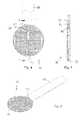
- FIG. 2is a perspective view of a resurfacing body according to an embodiment of the invention.
- FIG. 3is a side view of the resurfacing body of FIG. 2 .
- FIG. 4is top view of another configuration of the resurfacing body having a tab extending therefrom.
- FIG. 5is a sectional view of the resurfacing body taken along a line A-A in FIG. 4 .
- FIG. 6is a perspective view of the resurfacing body of FIG. 4 .
- FIG. 7is a top view of another configuration of the resurfacing body having a tab extending therefrom.
- FIG. 8is a sectional view of the resurfacing body taken along a line A-A in FIG. 7 .
- FIG. 9is a perspective view of the resurfacing body of FIG. 7 .
- FIG. 10is a top view of a guide probe assembly according to an embodiment of the invention.
- FIG. 11is a sectional view of the guide probe assembly taken along a line A-A in FIG. 10 .
- FIG. 12is an enlarged sectional view of a tip portion of the guide probe assembly.
- FIG. 13is a side view of a guide probe assembly according to an alternative embodiment of the invention.
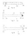
- FIG. 14is a perspective view of a guide cannula for use in conjunction with an embodiment of the invention.
- FIG. 15is a side view of the guide cannula of FIG. 14 .
- FIG. 16is a side view of a delivery cannula according to an embodiment of the invention.
- FIG. 17is a side view of an implant insertion tool according to an embodiment of the invention.
- FIG. 18is a side view of an implant insertion tool according to an alternative embodiment of the invention.
- FIG. 19is a side view of an implant insertion tool according to another alternative embodiment of the invention.
- FIG. 20is a side view of an implant countersink positioner according to an embodiment of the invention.
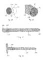
- FIG. 21is a top view of the resurfacing device positioned adjacent to a distal end of the implant insertion tool.
- FIG. 22is a perspective view of the resurfacing device in engagement with an extension on the distal end of the implant insertion tool.
- FIG. 23is a perspective view of the delivery cannula inserted into the guide cannula.
- FIG. 24is a perspective view of the implant insertion tool in an initial position where the resurfacing device is inside of the delivery cannula and where the delivery cannula is inside of the guide cannula.
- FIG. 25is a perspective view of the implant insertion tool in an inserted position where the resurfacing device is partially extending beyond the distal end of the delivery cannula.
- FIG. 26is a perspective view of the implant insertion tool in a partially retracted position where the resurfacing device is moved beyond the delivery cannula for implanting the resurfacing device in the facet joint.
- FIG. 27is a side view of a leaflet retractor tool for use in withdrawing the implant insertion tool from the delivery cannula.
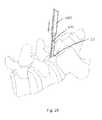
- FIG. 28is a perspective view of the guide probe assembly inserted into the facet joint and the guide cannula being inserted over the guide probe assembly.
- FIG. 29is a sectional view of the resurfacing device that has been implanted in one of the facet joints.
- FIG. 2One embodiment of an implant system 40 in accordance with principles of the invention and useful for treating a facet joint of a patient is illustrated in FIG. 2 .
- the implant system 40may include a superior resurfacing device 42 and an inferior resurfacing device 44 .
- the superior resurfacing device 42may be positioned on top of the inferior resurfacing device 44 so that the superior resurfacing device 42 and the interior resurfacing device 44 are oriented in opposite directions as the superior resurfacing device 42 and the inferior resurfacing device 44 would be oriented during the implantation process. Details on the various components of the resurfacing devices 42 , 44 are provided below.
- the resurfacing devices 42 , 44may be substantially similar to each other where the superior resurfacing device 42 is placed adjacent to a superior facet joint articular face (e.g., the superior articular face 26 of FIG. 1B ), and the inferior resurfacing device 44 is placed adjacent to an inferior facet joint articular face (e.g., the inferior articular face 28 of FIG. 1B ).
- the resurfacing devices 42 , 44may be capable of substantially conforming to the naturally-occurring shape or curvature of the facet joint anatomy.
- the resurfacing devices 42 , 44thereby replace the bone-on-bone interface of the natural facet joint in a manner achieving normal or near normal mobility.
- the resurfacing devices 42 , 44may be substantially similar to each other in some embodiments. As such, the following description of the superior resurfacing device 42 is equally applicable to the inferior resurfacing device 44 .
- the resurfacing device 42consists of a resurfacing body 46 .
- one or more additional componentscan be attached to, or extend from, the resurfacing body 46 .
- the resurfacing body 46may have a disc-like shape, that includes a base web 50 and a plurality of teeth 52 (referenced generally).
- the base web 50defines opposing major surfaces 54 , 56 , as illustrated in FIG. 3 , with the first major surface 54 providing or serving as an articulating surface (e.g., articulates relative to a corresponding articulating surface of the inferior resurfacing device 44 ( FIG. 2 )) as described below.
- the first major surface 54may also be referenced as the “articulating surface” of the resurfacing body 46 .
- the plurality of teeth 52may project from the second major surface 56 in a direction that is generally opposite the first major surface 54 .
- the base web 50defines an outer perimeter 58 of the resurfacing body 46 .
- the outer perimeter 58may have a generally circular shape that generally conforms to a shape of the facet joint in which the resurfacing body is to be implanted.
- the perimetermay have an oval-like shape (relative to a top or bottom plan view).
- the resurfacing device 44may be formed with other shapes, examples of which include square, rectangular, hexagonal and curvilinear.
- An overall size or footprint of the resurfacing body 46is defined by the outer perimeter 58 and can vary depending upon a size of the facet joint being treated, but is generally relatively small, especially as compared to conventional facet joint prostheses and/or capping devices. As is noted above, the resurfacing body 46 should be large enough to prevent bone-to-bone contact in the facet joint.
- a diameter of the resurfacing body 46may be in the range of between about 3 millimeters and about 15 millimeters. In other embodiments, the diameter of the resurfacing body may be in the range of between about 5 millimeters and about 10 millimeters.
- Facet joint treatment systems in accordance with this inventionmay be provided to a treating clinician with two or more different superior resurfacing devices 42 (and two or more different inferior resurfacing devices 44 ) each having a differently-sized resurfacing body 46 .
- Examples of the sizes of the resurfacing bodiesinclude about 5 millimeters, about 8 millimeters, about 10 millimeters and about 12 millimeters.
- the treating clinicianmay select the most appropriately sized resurfacing device for implantation based upon an evaluation of the facet joint to be treated.
- the resurfacing body 46While it is desirable for the resurfacing body 46 to be sufficiently large to prevent bone-to-bone contact within the facet joint, the resurfacing body 46 should not be too large such that the resurfacing body 46 extends beyond the facet joint as such a condition could result in damage to the tissue adjacent to the facet joint where the resurfacing body 46 is implanted.
- the resurfacing body 46may incorporate one or more features dictating a preferred insertion orientation and/or direction. For example, the resurfacing body 46 may be more readily inserted into, and subsequently retained within, a facet joint in a particular orientation.
- the outer perimeter 58can be described as generally defining a leading or distal end 70 , a trailing or proximal end 72 , and opposing sides 74 , 76 .
- the resurfacing body 46may be oriented such that the leading end 70 is initially inserted into the facet joint, followed by the trailing end 72 .
- the trailing end 72can form or define an engagement feature 80 , as illustrated in FIG. 2 , that promotes desired interaction with a separately-provided insertion tool, which is discussed in more detail below.
- the engagement feature 80is an aperture that includes at least two aperture regions 81 a , 81 b .
- the first aperture region 81 amay intersect the outer perimeter 58 or edge proximate the trailing end 72 .
- the second aperture region 81 bis in communication with the first aperture region 81 a and is oriented on a side of the first aperture region 81 a that is opposite the outer perimeter 58 .
- the first aperture region 81 amay have a width that is smaller than a width of the second aperture region 81 b .
- the shape of the engagement feature 80thereby provides a partially enclosed aperture to facilitate attachment of the resurfacing body 46 to the implant insertion tool during the insertion process.
- a force to separate the resurfacing body 46 from the implant insertion toolshould be sufficiently large so that the resurfacing body 46 does not inadvertently separate from the implant insertion tool 312 .
- the force to separate the resurfacing body 46 from the implant insertion tool 312is at least 1 Newton. In other embodiments, the force to separate the resurfacing body 46 from the implant insertion tool 312 is between about 1 Newton and about 10 Newtons. In still other embodiments, the separation force is about 5 Newtons.
- the separation forcemay be affected by a difference in the sizes of the widths of the first aperture region 81 a and the second aperture region 81 b and the width of the extension.
- the separation forcemay also be affected by other factors such as the rigidity of the resurfacing body 46 and the extension on the implant insertion tool 312 . For example, if the resurfacing body 46 or the extension is fabricated from a flexible material, the separation force may be lower if the resurfacing body 46 or the extension is fabricated from a relatively rigid material.
- the engagement feature 80may be formed at the same time the other portions of the resurfacing body 46 are formed such as by molding. Alternatively, the engagement feature 80 may be formed after the resurfacing body 46 is formed such as by stamping out the region that defines the first aperture region 81 a and the second aperture region 81 b.
- the frangible connectionmay be severed to thereby allow the implant insertion tool 312 to be removed while leaving the resurfacing body 46 in the facet joint.
- the force to sever the frangible connectionis at least 1 Newton. In other embodiments, the force to sever the frangible connection is between about 1 Newton and about 10 Newtons. In still other embodiments, the separation force is about 5 Newtons.
- the base web 50has, in some constructions, a relatively uniform thickness (e.g., nominal thickness variation of +/ ⁇ 0.05 mm), as illustrated in FIG. 3 .
- the base web 50forms the articulating surface 54 to be relatively smooth. This smoothness attribute is, at least in part, a function of the material employed for the resurfacing body 46 as described below.
- the articulating surface 54 of the base web 50may be coated with a separate layer that provides enhanced frictional (i.e., lower coefficient of friction) and wear characteristics.
- a separate layerthat provides enhanced frictional (i.e., lower coefficient of friction) and wear characteristics.
- An example of one such material having a low coefficient of frictionis polytetrafluoroethylene (PTFE), which is available under the designation TEFLON.
- the plurality of teeth 52project from the second major surface 56 of the base web 50 .
- These teeth 52may have a variety of forms.
- the teeth 52are arranged to form or define discrete zones or teeth sets, such as the first, second and third teeth sets 90 , 92 , 94 generally identified in FIG. 2 .
- the first teeth set 90may be centrally located along the base web 50 extending between the leading and trailing ends 70 , 72 .
- Individual teeth of the first teeth set 90may be generally identical. More particularly, each of the teeth may include a leading face 98 and a trailing face 100 that extends from the second major surface 56 and intersect at a tip 102 .
- the leading face 98may be oriented more proximate the leading end 70 (as compared to the trailing face 100 ), whereas the trailing face 100 may be oriented more proximate the trailing end 72 .
- the teethmay be constructed to define an insertion direction whereby an angle formed by the leading face 98 relative to the second major surface 56 is smaller than an angle formed by the trailing face 100 relative to the second major surface 56 .
- leading face 98may have a more gradual slope relative to the leading end 70 as compared to a slope of the trailing face 100 relative to the trailing end 72 such that the tooth 96 a more overtly engages a separate structure, such as the facet joint superior face (not shown) at and along the trailing face 100 as compared to the leading face 98 .
- the angle defined by the leading face 98may be in the range of 20°-60°, whereas the angle defined by the trailing face 100 is approximately 90°. Suitable angles may be affected by a variety of factors such as the material from which the resurfacing body 46 is fabricated. Regardless, and returning to FIG. 2 , the remaining teeth of the first teeth set 90 may be aligned with one another in two or more rows as shown.
- the second teeth set 92 and the third teeth set 94may be formed at or along the opposing sides 74 , 76 , respectively, as illustrated in FIG. 2 .
- an exterior face 104 associated with each tooth of the second and third teeth sets 92 , 94establish an angle of extension relative to the second major surface 56 that approaches 90°.
- the second and third teeth sets 92 , 94overtly resist side-to-side displacement of the resurfacing body 46 relative to a corresponding facet joint face following insertion.
- the second teeth set 92may resist leftward displacement of the resurfacing body 46
- the third teeth set 94may resist rightward displacement.
- each tooth of the plurality of teeth 52may have an identical, or nearly identical, height (or extension from the second major surface 56 ), as illustrated in FIG. 3 .
- the teeth of the first teeth set 90may have an elevated height as compared to teeth of the second and third teeth sets 92 , 94 , and combine to define a tapering height of the resurfacing body 46 from the leading end 70 to the trailing end 72 .
- a height of the leading tooth 96 ais greater than a height of a trailing tooth 96 b .
- the tips 102 associated with the teeth of the first teeth set 90combine to define a hypothetical plane P.
- the plane Pis, in some embodiments, non-perpendicular relative to a plane of the first major surface 54 , combining with the first major surface 54 to define an included angle in the range of between about 1° and about 5°.
- the teeth 52have substantially similar heights.
- the tallest tooth 96 amay be provided at the leading end 70 that ultimately is located opposite the point of insertion into the facet joint. As a result, the leading tooth 96 a may establish a more rigid engagement with the corresponding facet joint face to thereby overtly resist displacement upon final insertion.
- the base web 50 and the teeth 52combine to define an overall thickness T of the resurfacing body 46 .
- an overall thickness T of the resurfacing body 46For example, a lateral distance between the first major surface 54 and the tip 102 of the “tallest” tooth 96 a .
- a desired conformability characteristic of the resurfacing body 46is influenced by the overall thickness T and the base web thickness t, and thus the overall thickness T is selected, along with other parameters, to effectuate the desired degree of conformability.
- the overall thickness T of the resurfacing body 46is between about 0.25 millimeters and about 4 millimeters, although other dimensions are also contemplated.
- the overall thickness T associated with the resurfacing body 46 selected by the treating clinician for insertion into a particular facet jointmay vary as a function of other procedures associated with the insertion.
- the overall thickness Tcan be between about 0.5 millimeters and about 2.5 millimeters. If the insertion procedure entails first removing cartilage (or other tissue) from the facet joint, a larger version of the resurfacing body 46 can be inserted, such that the overall thickness T of the resurfacing body 46 is between about 0.5 millimeters and about 3 millimeters.
- the resurfacing devices 42 , 44and thus the corresponding resurfacing bodies 46 , may be integrally formed of a robust material that achieves desired conformability.
- the resurfacing body 46 in accordance with this inventionmaintains its structural integrity (i.e., little or no wear) without adhesive or cohesive damage when subjected to typical articulation of the facet joint with movement of the patient.
- the resurfacing devices 42 , 44may be formed of an implantable-grade plastic, although other materials such as metal are also available.
- the resurfacing devices 42 , 44may be made from the polyetherketone (PEK) family of plastics, which have strength, wear, flexibility, and biocompatibility properties appropriate for insertion into, and long-term functioning within, the facet joint.
- PEKpolyetherketone
- Polyetheretherketonehas been found to provide not only the conformability attributes described below, but also long-term mechanical strength and resistance to wear. Additional materials may be incorporated, such as those exhibiting radio-opacity properties.
- the resurfacing devices 42 , 44may be formed from a radio-opaque mineral (e.g., barium)-loaded PEK composition.
- Radio-opaque marker bandse.g., platinum marker band
- the marker band(s)can be embedded within the resurfacing device 42 , 44 .
- a radio-opaque rodmay be inserted into a hole formed in the resurfacing device 42 , 44 , as illustrated in FIG. 5 .
- the radio-opaque materialmay be inserted around a perimeter of the resurfacing device 42 , 44 .
- the selected materials, shapes, and dimensions associated with the resurfacing body 46 of each of the resurfacing devices 42 , 44impart or create a conformability property to the resurfacing body 46 sufficient to allow the resurfacing body 46 to “match” the multi-planar concavity associated with a native facet joint articular face anatomy.
- the resurfacing body 46forms an entirety of the corresponding resurfacing device 42 , 44 .
- one or more additional componentsmay be included with the resurfacing body 46 , such that the following explanation of conformability is specifically applicable to the resurfacing body 46 , but may also apply equally to the resurfacing devices 42 , 44 as a whole.
- “conformability”may be inversely proportional to bending stiffness of the resurfacing body 46 during insertion, and may be increased as the resurfacing body 46 heats to body temperature and is allowed to creep. From a clinical perspective, “conformability” of the resurfacing body 46 entails the resurfacing body 46 conforming to a radius of curvature of the C-shaped or J-shaped portions of the articular joint such as the concave-shaped superior articular face 26 of FIG. 1B or the convex-shaped inferior articular face 28 of FIG. 1B .
- the minimum radius of curvature of the human facet joint in the transverse planeis on the order of 20 millimeters, with a lower bound (10th percentile) on the order of 7 millimeters.
- the radius of curvaturewill vary with the vertebral level and the patient's specific anatomy and disease state. Preparation of the facet joint prior to insertion of the resurfacing devices 42 , 44 may also change the radius of curvature.
- a range of curvature radii of 7 millimeters to infinitycan be accommodated by the resurfacing devices 42 , 44 of the present disclosure.
- the conformability characteristic of the resurfacing body 46is sufficient such that the resurfacing body 46 readily transition from the relatively flat state illustrated in FIG. 2 to an inserted state (not shown but reflected, for example, in FIG. 30 ) in which the resurfacing body 46 substantially matches or mimics the naturally-occurring shape (e.g., radius of curvature of curved portions) of the facet joint face to which the resurfacing body 46 is secured.
- the facet joint 20( FIG. 1B ) is subject to, or experiences, various loads that effectuate compressive forces at the region of interface between the superior and inferior articular faces 26 , 28 ( FIG. 1B ).
- Compressive loads normal to and across the articular faces 26 , 28will be generated upon separation/posterior translation of the superior facets due to joint capsule tensioning.
- the conformable nature of the resurfacing body 46is such that in the presence of these typical compressive forces, the resurfacing body 46 will transition from the relatively flat state to the inserted state in which the resurfacing body 46 substantially matches the geometry of the facet joint surface to which the resurfacing body 46 is secured.
- the resurfacing body 46will flex to conform with a macroscopic shape/contour of the native articular face to which the resurfacing body 46 is applied, but may not conform to the microscopic variations in the native articular face because of small deviations due to cartilage defects, bony fissures, or small voids during preparation of the joint (typically between about 0.05 millimeters and about 0.5 millimeters in width).
- a resurfacing body that conforms to the minimum radius of curvature of an adult human facet joint under normal physiologic forcese.g., between about 180 and about 450 Newtons/millimeter per segment assuming a net 1 millimeter posterior shear translation
- a resurfacing body that conforms to the minimum radius of curvature of an adult human facet joint under normal physiologic forcese.g., between about 180 and about 450 Newtons/millimeter per segment assuming a net 1 millimeter posterior shear translation
- a resurfacing body sized for placement within an adult human facet joint and exhibiting a Conformability Factor (described below) of not more than 100 Newtonsis also defined as being “conformable” and “substantially matching” the multi-planar curvatures of a facet joint in accordance with the present disclosure.
- resurfacing bodies in accordance with the present disclosureexhibit a Conformability Factor of not more than 50 Newtons, and in other embodiments not more than 25 Newtons.
- FIGS. 4-6Another embodiment of the resurfacing body 46 is illustrated in FIGS. 4-6 .
- the resurfacing body 46may have a similar over shape and a similar tooth pattern to the resurfacing body illustrated in FIGS. 2-3 except as noted below.
- the resurfacing body 46may include a radio opaque marker 82 placed therein.
- the radio opaque marker 82may be utilized to monitor the location of the resurfacing body 46 is implanted in a non-invasive manner as the radio opaque marker 82 may be viewed using many different types of imaging conventionally used in the medical field.
- the radio opaque marker 82should be sufficiently large to facilitate viewing the radio opaque marker using conventional medical imaging techniques. However, the radio opaque marker 82 should be sufficiently small such that the radio opaque marker 82 does not impede the flexibility of the resurfacing body 46 after implantation. Alternatively or additionally, the radio opaque marker 82 may be fabricated from a flexible material that does not impede the ability of the resurfacing body 46 to flex after implantation.
- radio opaque marker 82While it is possible to incorporate the radio opaque marker 82 during the process used to fabricate the resurfacing body 46 , it is also possible to insert the radio opaque marker 82 into the resurfacing body 46 after fabrication.
- One such suitable technique for inserting the radio opaque marker 82 into the resurfacing deviceincludes forming an aperture in the resurfacing body 46 .
- the aperturemay be formed using a drill.
- the radio opaque marker 82may be placed into the resurfacing body 46 from a trailing end 72 thereof proximate a center line of the resurfacing body 46 . Using such a configuration provides the resurfacing body 46 with symmetry to assist in evaluating the position of the resurfacing body 46 based upon medical imaging of the radio opaque marker 82 .
- the placement of the radio opaque marker 82 in the resurfacing body 46should be relatively accurate such that the radio opaque marker 82 does not extend through one of the surfaces of the resurfacing body 46 . Such an occurrence could lead to degradation of the resurfacing body 46 or could cause damage to the tissue in the facet joint that is adjacent to the resurfacing body 46 .
- an additional material region 84may be provided in the region adjacent to the radio opaque marker 82 , as illustrated in FIGS. 4 and 5 .
- the radio opaque marker 82may be placed at an approximately equal distance between the upper and lower surfaces of the resurfacing body in the additional material region 84 .
- An elongated tab 86may extend from the trailing end 72 of the resurfacing body 46 .
- the elongated tab 86could be used in the manufacturing process and then be severed from the other portions of the resurfacing body 46 once manufacturing is completed.
- the elongated tab 86may be used in conjunction with the insertion of the resurfacing body 46 into the facet joint as opposed to the implantation system described herein. In such instances, a line of weakening may be provided where the elongated tab 84 intersects the resurfacing body 46 .
- FIGS. 7-9Another embodiment of the resurfacing body 46 is illustrated in FIGS. 7-9 .
- the resurfacing body 46may have a similar over shape and a similar tooth pattern to the resurfacing body illustrated in FIGS. 2-3 except as noted below.
- the resurfacing body 46may include a radio opaque marker 82 placed therein.
- the radio opaque marker 82may be utilized to monitor the location of the resurfacing body 46 is implanted in a non-invasive manner as the radio opaque marker 82 may be viewed using many different types of imaging conventionally used in the medical field.
- the features and placement of the radio opaque marker 82are similar to the features and placement of the radio opaque marker 82 in the embodiment of the resurfacing body 46 illustrated in FIGS. 4-6
- An elongated tab 86may extend from the trailing end 72 of the resurfacing body 46 .
- the structure and function of the elongated tab 86may be to the structure and function of the elongated tab 86 in the embodiment of the resurfacing body 46 illustrated in FIGS. 4-6 .
- the resurfacing body 46and thus the system 40 , may be delivered to, and inserted within, a facet joint in a variety of manners via various instrumentations sets or systems. Components of one useful insertion tooling set are discussed below.
- One of the important aspects of accurately delivering the resurfacing body 46is to not only accurately locate the desired facet joint but also to accurately position the resurfacing body delivery system with respect to the facet joint to permit the resurfacing body 46 to be accurately inserted into the facet joint.
- a guide probe assembly 200may be initially used to locate the region in the facet joint where the resurfacing device 46 is to be inserted.
- the guide probe assembly 200may include a guide probe shaft 202 and a guide probe tip 204 that extends from a distal end of the guide probe shaft 202 .
- the guide probe shaft 202may have a substantially rectangular profile, as illustrated in FIGS. 10 and 11 . Forming the guide probe shaft 202 with the substantially rectangular profile enables the guide cannula 260 to slide over the guide probe assembly 200 after the guide probe assembly 200 is positioned with the guide probe tip 204 at least partially in the facet joint, as is discussed in more detail herein. This process reduces the time associated with implanting the resurfacing body 46 when compared to an implantation system that does not utilize this insertion process.
- the guide probe shaft 202may be formed with a width and a height that is approximately equal to a width and a height of the resurfacing body 46 .
- the guide probe shaft 202has a width of between about 5 millimeters and about 20 millimeters. In other embodiments, the guide probe shaft 202 has a width of about 12 millimeters.
- the guide probe shaft 202has a thickness of between about 0.20 millimeters and about 10 millimeters. In other embodiments, the guide probe shaft 202 has a thickness of about 2 millimeters.
- the guide probe shaft 202is formed with a length that enables a proximal end of the guide probe shaft 202 to be positioned outside of the patient's body when the distal end of the guide probe shaft 202 is adjacent the facet joint. Such a configuration facilitates the surgeon or other person who is using the guide probe assembly 200 to accurately position the guide probe assembly 200 with respect to the facet joint.
- the guide probe shaft 202has a length of between about 10 centimeters and about 30 centimeters. In other embodiments, the guide probe shaft 202 has a length of about 23 centimeters.
- the distal end of the guide probe shaft 202may include a tapered region 206 , as illustrated in FIGS. 10-11 , to provide a transition between the guide probe shaft 202 and the guide probe tip 204 .
- the length of the tapered region 206may depend on a variety of factors such as a difference in the width and the height of the guide probe shaft 202 and the guide probe tip 204 .
- the guide probe shaft 202may be fabricated from a relatively rigid material to facilitate the use of the guide probe shaft 202 to locate the facet joint using the guide probe tip 204 .
- the guide probe shaft 202may be fabricated from stainless steel. In other embodiments, it is possible to fabricate the guide probe shaft 202 from a non-metallic material such as plastic.
- the guide probe shaft 202be fabricated from a material that is biocompatible. If it is desired to reuse the guide probe shaft 202 for multiple surgical procedures, the guide probe shaft 202 should be capable of withstanding repeated sterilization processes such as by using an autoclave.
- the guide probe tip 204is operably connected to the proximal end of the guide probe shaft 202 .
- the guide probe shaft 202has an aperture 210 formed in the distal end thereof. This aperture 210 is adapted to receive a portion of the guide probe tip 204 .
- the portion of the guide probe tip 204 that extends into the aperture 210may have a length that is greater than a length of the guide probe tip 204 that extends beyond the proximal end of the guide probe shaft 202 to enhance the ability of the guide probe tip 204 when attempting to locate a desire location in the facet joint.
- Forming the guide probe tip 204 separate from the other portions of the guide probe assembly 200enables guide probe tips 202 having different widths and/or lengths to be used depending on the size, shape and location of the facet joint in which the resurfacing device is being inserted.
- the guide probe tip 204may have a thickness and a width that are both smaller than a thickness and a width of the guide probe shaft 202 .
- the guide probe tip 104has a width of between about 5 millimeters and about 20 millimeters. In other embodiments, the guide probe tip 104 may have a width that is about 9 millimeters.
- the guide probe tip 204may have a thickness of between about 0.10 millimeters and about 0.50 millimeters. In other embodiments, the guide probe tip 204 may have a thickness of about 0.20 millimeters.
- the guide probe tip 204may be formed with a proximal end that is not pointed. Forming the guide probe tip 204 with this configuration at the proximal end minimizes the potential that the guide probe tip 204 will damage or other negatively impact the tissue in the facet joint or surrounding the facet joint.
- proximal end of the guide probe tip 204it is possible for the proximal end of the guide probe tip 204 to be sharpened such that the guide probe tip 204 may be used to cut tissue when attempting to access the facet joint.
- the guide probe tip 204may be fabricated from a material that is rigid but which is flexible. Forming the guide probe tip 204 from a flexible material enhances the ability of the guide probe tip 204 to be positioned at least partially in the facet joint as an initial step in implanting the resurfacing body 46 .
- the guide probe tip 204is fabricated from a metallic material such as stainless steel. It is also possible to fabricate the guide probe tip 204 from a non-metallic material using the concepts of the invention.
- the material that is used to fabricate the guide probe tip 204is that the material be biocompatible. If it is desired to reuse the guide probe tip 204 for multiple surgical procedures, the guide probe tip 204 should be capable of withstanding repeated sterilization processes such as by using an autoclave.
- the guide probe tip 204may be attached to the guide probe shaft 202 using at least one fastening device 212 . In certain embodiment at least two of the fastening devices 212 are used to attached the guide probe tip 204 to the guide probe shaft 202 .
- the fastening device 212may have a variety of different configurations. In one configuration, the fastening device 212 frictionally engages the guide probe shaft 202 through the aperture formed therein. Alternatively, the fastening device 212 may have a threaded side surface that enables the fastening device 212 to be screwed into the guide probe shaft 202 having an aperture with a complementary shape.
- the guide probe assembly 240includes an elongated main portion 242 and a handle portion 244 that is attached to a proximal end of the main portion 242 .
- the main portion 242may have a configuration that is similar to the guide probe shaft 202 illustrated in FIGS. 10-11 . While FIG. 13 illustrates that the main portion 242 does not have a separate tip portion, it is possible to adapt the concepts of this embodiments to encompass a separate tip portion so that the tip portion may possess different physical characteristics that the main portion 242 from which the tip portion extends. Even when a separate tip portion is not provided, a proximal end of the main portion 242 may be tapered to facilitate guiding the guide probe assembly 240 to a desired location in the facet joint.
- the handle portion 244enhances the ability to grasp the guide probe assembly 240 during the insertion process.
- the handle portion 244may have a width that is greater than a width of the main portion 242 .
- the handle portion 244may also have a thickness that is greater than a thickness of the main portion 242 .
- the guide probe assembly 240may be used in conjunction with the guide probe assembly 200 .
- the main portion 242may be placed adjacent to the guide probe assembly 200 .
- the main portion 242 and the guide probe assembly 200may be thinner than with the separately used configuration so that the main portion 242 and the guide probe assembly 200 may both fit inside of the guide cannula 260 .
- This configurationmay utilize the handle portion 244 for guiding the distal end of the guide probe assembly 200 into a position within the facet joint. Thereafter, the guide probe assembly 240 may be withdrawn. Next, the guide cannula 260 may be placed over the guide probe assembly 200 .
- the delivery systemmay include a guide cannula 260 , as illustrated in FIGS. 14 and 15 .
- the guide cannula 260has an internal passage 262 that extends from a proximal end to a distal end thereof.
- the passage 262may have a generally rectangular configuration.
- a width of the passage 262is smaller than a width of the delivery cannula 280 .
- the width of the passage 262may be between about 3 millimeters and about 15 millimeters. In other embodiments, the width of the passage 262 is between about 5 millimeters and about 10 millimeters.
- a height of the passage 262is smaller than a height of the delivery cannula 280 .
- the height of the passage 262may be between about 0.50 millimeters and about 5 millimeters. In other embodiments, the height of the passage 262 is about 2 millimeters.
- the proximal end of the guide cannula 260may have a concave surface 266 .
- the concave surface 266may at least partially receive a convex surface of the facet joint to thereby prevent the guide cannula 260 from moving laterally with respect to the facet joint and thereby enhance the ability to accurately insert the resurfacing device into the facet joint.
- the guide cannula 260may include a first stop mechanism 270 proximate a distal end thereof.
- the first stop mechanism 270limits a distance the delivery cannula 280 may be inserted into the guide cannula 260 .
- the first stop mechanism 270engages a stop surface 286 that extends from an outer surface of the delivery cannula 280 proximate a distal end thereof.
- the guide cannula 260may also include a second stop mechanism 272 extending from the proximal end thereof.
- the second stop mechanism 272limits a distance the implant insertion tool 300 may be inserted into the guide cannula 260 to thereby prevent over-insertion of the resurfacing device 46 into the facet joint.
- the second stop mechanism 272may engage a shoulder 320 on the implant insertion tool 310 when the implant insertion tool 310 has been extended a desired distance into the guide cannula 260 .
- the second stop mechanism 272may be positioned in a spaced-apart relationship with respect to the first stop mechanism 270 .
- a spacing between the first stop mechanism 270 and the second stop mechanism 272is between about 1 centimeter and about 5 centimeters.
- the guide cannula 260thereby facilitates extending the guide probe shaft 202 into the proximal end of the rectangular passage 262 until the proximal end of the guide cannula 260 is adjacent to the facet joint. Thereafter, the guide probe assembly 200 may be withdrawn from the guide cannula 260 by pulling the distal end of the guide probe assembly 200 .
- the guide cannula 260may be fabricated with a length that enables the distal end to be positioned proximate to the facet joint where the implant is to be inserted while the proximal end is positioned outside of the person's body. In certain embodiments, the guide cannula 260 may have a length of between about 10 centimeters and about 30 centimeters.
- the delivery cannula 280may have a generally rectangular profile with a width and a height that are both slightly smaller than the width and the height of the guide cannula 260 . This configuration enables the delivery cannula 280 to be inserted into the guide cannula 260 after the guide stop assembly 200 has been removed from the guide cannula 260 .
- the delivery cannula 280has an internal passage 282 that extends from a proximal end to a distal end thereof.
- the passage 282may have a generally rectangular configuration.
- a width of the passage 282is smaller than a width of the main portion 312 of the implant insertion tool 310 .
- the width of the passage 282may be between about 3 millimeters and about 15 millimeters. In other embodiments, the width of the passage 282 is between about 5 millimeters and about 10 millimeters.
- a height of the passage 282is smaller than a height of the main portion 312 of the implant insertion tool 310 .
- the height of the passage 282may be between about 0.5 millimeters and about 5 millimeters. In other embodiments, the height of the passage 282 is about 2 millimeters.
- the sides of the passage 282may be removed so that an upper face and a lower face of the delivery cannula 280 define a pair of arms.
- the implant insertion tool 310When the implant insertion tool 310 is inserted into the delivery cannula 280 , at least a part of the shoulder portion 320 may have a width that is greater than the width of the delivery cannula 280 , as illustrated in FIG. 24 . This configuration thereby limits the distance that the implant insertion tool 310 may be inserted into the delivery cannula 280 .
- the delivery cannula 280may include a pair of leaflets 284 that extend from a distal end thereof.
- the leaflets 284may be fabricated from a resilient material.
- the leaflets 284may be initially positioned adjacent each other.
- the leaflets 284may have a width that is approximately the same as a width of the resurfacing body 46 .
- a distal end of the leaflets 284may be curved. The curved distal end of the leaflets 284 thereby minimizes damage to the superior articular face and the inferior articular face of the facet joint as the leaflets are moved into a position at least partially within the facet joint to provide an opening in the facet joint that is adapted to receive the resurfacing body 46 .
- the leaflets 284may deflect away from each other as the resurfacing body 46 and the distal end of the implant insertion tool 310 extend therebetween. The leaflets 284 thereby enable maintaining the resurfacing body 46 in engagement with the implant insertion tool 310 .
- the force required to separate the leaflets 284should be sufficiently large so that the leaflets 284 are retained in the closed configuration. However, the force should not be too great such that it is difficult for the resurfacing body 46 to be urged between the leaflets 284 during the implantation process or that the leaflets 46 damage the resurfacing body 46 when passing between the leaflets 284 .
- a stop mechanism 286may extend from at least one outer surface of the delivery cannula 280 .
- the stop mechanism 286may be an elevated region that is oriented generally transverse to an axis of the delivery cannula 280 .
- the stop mechanism 286may comprise two elevated regions that are mounted in a spaced-apart configuration, as illustrated in FIG. 16 .
- the two elevated regionsthereby define a channel 288 that extends therebetween.
- the channel 288is adapted to receive a portion of a leaflet retractor tool 360 , which may be used to withdraw the delivery cannula 280 from the guide cannula 260 .
- the stop mechanism 286engages the first stop mechanism 270 on the guide cannula 260 .
- the stop mechanism 286thereby limits a distance to which the delivery cannula 280 may be inserted into the guide cannula 260 .
- An embodiment of the inventionmay also include an implant insertion tool 310 , as illustrated in FIG. 17 .
- the implant insertion tool 310may include a main portion 312 and a handle portion 314 that is attached to a proximal end of the main portion 312 .
- the main portion 312may have a width and a height that are slightly smaller than the width and the height of the delivery cannula 280 . This configuration enables the main portion 312 to be placed inside of and slide with respect to the delivery cannula 280 during the process of inserting the resurfacing body 46 .
- the width of the main portion 312may be between about 3 millimeters and about 15 millimeters. In other embodiments, the width of the main portion 312 is between about 1 millimeter and about 5 millimeters.
- the height of the main portion 312may be between about 0.5 millimeters and about 5 millimeters. In other embodiments, the width of the main portion 312 is about 2 millimeters.
- the main portion 312may include a shoulder 320 extending from at least one side thereof.
- the shoulder 320may be used to limit a distance to which the implant insertion tool 310 may be inserted into the delivery cannula by engaging the second stop mechanism 272 on the guide cannula 260 .
- the handle portion 314may be oriented generally perpendicular to the main portion 312 .
- the handle portion 314thereby provides an enlarged surface that may be used to grasp the implant insertion tool 310 and thereby facilitates manipulating the implant insertion tool 310 .
- the length of the handle portion 314may be between about 5 centimeters and about 15 centimeters.
- a distal end 322 of the main portion 312may include a concave surface 323 that is curved to at least partially conform to a surface of the resurfacing body 46 .
- the concave surfacethereby enhances the ability to retain the resurfacing body 46 in a desired position with respect to the implant insertion tool 310
- an extension 324may extend from the distal end 322 .
- the extension 324is adapted to engage the engagement feature 80 that is provided in the resurfacing body 46 .
- the extension 324may have a shape that is similar to but slightly smaller than the engagement feature 80 .
- the extension 324may include a first extension region 326 a and a second extension region 326 b.
- the first extension region 326 ahas a width that is smaller than the width of the first aperture region 81 a .
- the second extension region 326 bhas a width that is larger than the width of the first aperture region 81 a and smaller than the width of the second aperture region 81 b .
- This configurationenables the extension 324 to be retained in the engagement feature 80 to prevent the resurfacing body 46 from being separated from the implant insertion tool 310 . More details on the relative size of the engagement feature 80 and the extension 324 are discussed above.
- FIGS. 21 and 22illustrate the relationship between the resurfacing body 46 and the implant insertion tool 310 .
- the resurfacing body 46is placed adjacent to but spaced-apart from the implant insertion tool 310 .
- the resurfacing body 46is in engagement with the implant insertion tool 310 such that the extension 324 extends into and engages the engagement feature 80 .
- the shape of the engagement feature 80may be approximately the same as the shape of the extension 324 .
- the implant insertion tool 310is configured to be inserted into the delivery cannula 280 and the guide cannula 260 until the handle portion 314 engages the second stop mechanism 272 on the guide cannula 260 . This configuration protects against inadvertent over insertion of the resurfacing body 46 .
- implant insertion tools 330 and 340provide for selected countersinking of the resurfacing body 46 in the facet joint.
- the implant insertion tools 330 , 340have a similar configuration to the implant insertion tool 310 illustrated in FIG. 17 .
- the implant insertion tool 330 in FIG. 18includes a countersink extension 332 that extends from the distal end thereof.
- the countersink extension 332may have a concave end surface 334 that with a curvature that is similar to a curvature of the resurfacing body 46 .
- an extension 336is provided on the countersink extension 332 that facilitates attachment of the resurfacing implant 46 to the implant insertion tool 330 .
- the end surface 334is spaced apart from the concave surface 322 .
- the distance between the end surfacesmay be between about 1 millimeter and about 10 millimeters. In other embodiments, the distance between the end surfaces may be about 3 millimeters.
- the countersink extension 332may have a width and a height that are smaller than the width and the height of the main portion 312 . Such a configuration minimizes the potential of contact between the countersink extension 332 and the tissue within the facet joint, as such contact could cause undesirable side effects.
- the implant insertion tool 340 in FIG. 19is similar to the implant insertion tool 330 in FIG. 18 except that the countersink extension 342 is slightly longer.
- the countersink extension 342may have a length of about 5 millimeters.
- the countersink positioner 350is similar to the implant insertion tool 330 illustrated in FIG. 18 except that the countersink positioned 350 does not include an extension extending from a distal end thereof.
- the countersink positioner 350may thereby be utilized after the resurfacing body 46 has been inserted into the facet joint when it is recognized that the resurfacing body 46 is not inserted far enough into the facet joint. After removing the implant insertion tool 310 from the delivery cannula 280 , the countersink positioner 350 is inserted into the delivery cannula 280 .
- the handle portion 352 on the countersink positioner 350limits the distance that the countersink positioner 350 may be inserted into the delivery cannula 280 so that the resurfacing body 46 may be accurately positioned within the facet joint.
- an incisionis made in the patient proximate to the facet joint where it is desired to implant the resurfacing body 46 .
- the guide probe assembly 200is inserted into the patient so that the guide probe tip 204 can be used to identify the joint line in the facet joint.
- the guide cannula 260is slid over the guide probe assembly 200 , as illustrated in FIG. 28 , until the distal end of the guide cannula 260 is adjacent to the facet joint.
- the guide probe assembly 200thereby enables the guide cannula 260 to be accurately and quickly placed in the location for the implanting process.
- the guide probe assembly 200is then withdrawn from the guide cannula 260 with care being exercised to maintain the guide cannula 260 in a stationary position with respect to the facet joint. Thereafter, the delivery cannula 280 is inserted into the guide cannula 260 until a rib 281 on the delivery cannula 280 engages the first stop mechanism 270 , as illustrated in FIG. 23 .
- the first stop mechanism 270thereby limits the distance to which the delivery cannula 280 may be inserted into the guide cannula 260 .
- the leaflets 284extend from the distal end of the guide cannula 260 . As the distal end of the guide cannula 260 is adjacent to the facet joint, the leaflets 284 extend into the facet joint to cause a region to be formed where the resurfacing body 46 may be inserted in subsequent operations.
- the resurfacing body 46is positioned adjacent to the distal end of the implant insertion tool 310 so that the extension 324 extends into the engagement feature 80 , as illustrated in FIG. 22 .
- the implant insertion tool 310is then inserted into the proximal end of the delivery cannula 280 .
- the resurfacing body 46is recessed in the delivery cannula 280 , as illustrated in FIG. 24 .
- leaflet spreader(not shown) that maintains the leaflets 284 in a spaced apart configuration such that the resurfacing body 46 may be positioned between the leaflets 284 . If it is desired to use the leaflet spreader, the loading process may be changed slightly so that the resurfacing body 46 is attached to the implant insertion tool 310 and then the implant insertion tool 310 is inserted into the delivery cannula 280 .
- the insertion of the implant insertion tool 310is continued until the resurfacing body 46 begins to extend from the distal end of the delivery cannula 280 , as illustrated in FIG. 24 .
- the shoulder 320engages the second stop mechanism 272 to limit the distance to which the implant insertion tool 310 may be inserted into the delivery cannula 280 .
- the leaflets 284are deflectable to provide a space for the resurfacing body 46 to be inserted into the facet joint.
- the delivery cannula 280is urged away from the facet joint, as illustrated in FIG. 26 .
- This motioncauses the leaflets 284 to be refracted to within the delivery cannula 280 .
- the facet jointreturns to its initial position, which causes the resurfacing body 46 to fill the space between the bones.
- leaflet retractor tool 360such as is illustrated in FIG. 27 to cause the delivery cannula 280 to be urged away from the facet joint.
- the leaflet refractor tool 360includes a first handle section 362 and a second handle section 364 that are pivotally mounted with respect to each other.
- the first handle section 362engages the handle portion 314 on the implant insertion tool 310 .
- the handle portion 314may have an aperture that extends therethrough and the first handle section 362 may be extended through the aperture to secure the leaflet retractor tool 360 with respect to the implant insertion tool 310 .
- an end of the second handle section 364engages a lip 366 extending from the delivery cannula 280 proximate a proximal end thereof.
- the second handle section 364is pivoted with respect to the first handle section 362 as indicated by arrow 368 .
- This pivoting motioncauses the delivery cannula 280 to be urged away from the facet joint so that the leaflets 284 are retracted to within the guide cannula 260 .
- This motionis towards the facet joint to reduce the potential that the guide cannula 260 is moved from its desired position against the facet joint during the implanting process.
- the implant insertion tool 310may be separated from the resurfacing body 46 using a gentle pull away from the resurfacing body 46 to leave the resurfacing devices 42 , 44 in the facet joint as illustrated in FIG. 29 .
- the implantation processis thereby complete. Medical imaging may be used to evaluate whether the resurfacing body has been accurately implanted prior to removing the guide cannula 260 from adjacent to the facet joint.
Landscapes
- Health & Medical Sciences (AREA)
- Orthopedic Medicine & Surgery (AREA)
- Engineering & Computer Science (AREA)
- Biomedical Technology (AREA)
- Life Sciences & Earth Sciences (AREA)
- Veterinary Medicine (AREA)
- Heart & Thoracic Surgery (AREA)
- Public Health (AREA)
- Animal Behavior & Ethology (AREA)
- General Health & Medical Sciences (AREA)
- Transplantation (AREA)
- Neurology (AREA)
- Surgery (AREA)
- Oral & Maxillofacial Surgery (AREA)
- Vascular Medicine (AREA)
- Cardiology (AREA)
- Nuclear Medicine, Radiotherapy & Molecular Imaging (AREA)
- Medical Informatics (AREA)
- Molecular Biology (AREA)
- Physical Education & Sports Medicine (AREA)
- Physics & Mathematics (AREA)
- Otolaryngology (AREA)
- Plasma & Fusion (AREA)
- Electromagnetism (AREA)
- Prostheses (AREA)
- Surgical Instruments (AREA)
Abstract
Description
Claims (10)
Priority Applications (1)
| Application Number | Priority Date | Filing Date | Title |
|---|---|---|---|
| US13/972,060US9314277B2 (en) | 2010-06-15 | 2013-08-21 | Systems and methods for facet joint treatment |
Applications Claiming Priority (3)
| Application Number | Priority Date | Filing Date | Title |
|---|---|---|---|
| US35514010P | 2010-06-15 | 2010-06-15 | |
| US13/084,104US8663293B2 (en) | 2010-06-15 | 2011-04-11 | Systems and methods for facet joint treatment |
| US13/972,060US9314277B2 (en) | 2010-06-15 | 2013-08-21 | Systems and methods for facet joint treatment |
Related Parent Applications (1)
| Application Number | Title | Priority Date | Filing Date |
|---|---|---|---|
| US13/084,104DivisionUS8663293B2 (en) | 2010-06-15 | 2011-04-11 | Systems and methods for facet joint treatment |
Publications (2)
| Publication Number | Publication Date |
|---|---|
| US20140243896A1 US20140243896A1 (en) | 2014-08-28 |
| US9314277B2true US9314277B2 (en) | 2016-04-19 |
Family
ID=44504140
Family Applications (2)
| Application Number | Title | Priority Date | Filing Date |
|---|---|---|---|
| US13/084,104Expired - Fee RelatedUS8663293B2 (en) | 2010-06-15 | 2011-04-11 | Systems and methods for facet joint treatment |
| US13/972,060Active2032-03-27US9314277B2 (en) | 2010-06-15 | 2013-08-21 | Systems and methods for facet joint treatment |
Family Applications Before (1)
| Application Number | Title | Priority Date | Filing Date |
|---|---|---|---|
| US13/084,104Expired - Fee RelatedUS8663293B2 (en) | 2010-06-15 | 2011-04-11 | Systems and methods for facet joint treatment |
Country Status (10)
| Country | Link |
|---|---|
| US (2) | US8663293B2 (en) |
| EP (1) | EP2582330A1 (en) |
| JP (1) | JP5675969B2 (en) |
| KR (1) | KR20130122929A (en) |
| CN (1) | CN103237525A (en) |
| AU (1) | AU2011265712B2 (en) |
| BR (1) | BR112012031947A2 (en) |
| CA (1) | CA2802791A1 (en) |
| RU (1) | RU2012155518A (en) |
| WO (1) | WO2011159440A1 (en) |
Cited By (24)
| Publication number | Priority date | Publication date | Assignee | Title |
|---|---|---|---|---|
| US9456855B2 (en) | 2013-09-27 | 2016-10-04 | Spinal Elements, Inc. | Method of placing an implant between bone portions |
| US9517077B2 (en) | 2007-02-22 | 2016-12-13 | Spinal Elements, Inc. | Vertebral facet joint drill and method of use |
| US9572602B2 (en) | 2011-02-24 | 2017-02-21 | Spinal Elements, Inc. | Vertebral facet joint fusion implant and method for fusion |
| USD780315S1 (en) | 2013-03-14 | 2017-02-28 | Spinal Elements, Inc. | Flexible elongate member with a portion configured to receive a bone anchor |
| US9675387B2 (en) | 2004-02-06 | 2017-06-13 | Spinal Elements, Inc. | Vertebral facet joint prosthesis and method of fixation |
| USD790062S1 (en) | 2011-10-26 | 2017-06-20 | Spinal Elements, Inc. | Interbody bone implant |
| US9743937B2 (en) | 2007-02-22 | 2017-08-29 | Spinal Elements, Inc. | Vertebral facet joint drill and method of use |
| US9808294B2 (en) | 2011-02-24 | 2017-11-07 | Spinal Elements, Inc. | Methods and apparatus for stabilizing bone |
| US9820784B2 (en) | 2013-03-14 | 2017-11-21 | Spinal Elements, Inc. | Apparatus for spinal fixation and methods of use |
| US9839451B2 (en) | 2016-03-29 | 2017-12-12 | Christopher D. Sturm | Facet joint replacement device and methods of use |
| US9839450B2 (en) | 2013-09-27 | 2017-12-12 | Spinal Elements, Inc. | Device and method for reinforcement of a facet |
| US9931142B2 (en) | 2004-06-10 | 2018-04-03 | Spinal Elements, Inc. | Implant and method for facet immobilization |
| US10251679B2 (en) | 2013-03-14 | 2019-04-09 | Spinal Elements, Inc. | Apparatus for bone stabilization and distraction and methods of use |
| US10758361B2 (en) | 2015-01-27 | 2020-09-01 | Spinal Elements, Inc. | Facet joint implant |
| US11304733B2 (en) | 2020-02-14 | 2022-04-19 | Spinal Elements, Inc. | Bone tie methods |
| US11457959B2 (en) | 2019-05-22 | 2022-10-04 | Spinal Elements, Inc. | Bone tie and bone tie inserter |
| US11464552B2 (en) | 2019-05-22 | 2022-10-11 | Spinal Elements, Inc. | Bone tie and bone tie inserter |
| US11478275B2 (en) | 2014-09-17 | 2022-10-25 | Spinal Elements, Inc. | Flexible fastening band connector |
| US11937869B1 (en) | 2023-01-20 | 2024-03-26 | Panacea Spine, LLC | Electrocautery rhizotomy using wanding of energized electrocautery probe |
| US12102348B2 (en) | 2016-09-07 | 2024-10-01 | Vertos Medical, Inc. | Percutaneous lateral recess resection methods and instruments |
| US12239362B2 (en) | 2023-01-20 | 2025-03-04 | Panacea Spine, LLC | Pain treatment using wanding of percutaneous surgical probe over sensory nerve |
| US12324572B2 (en) | 2022-06-16 | 2025-06-10 | Vertos Medical, Inc. | Integrated instrument assembly |
| US12369952B2 (en) | 2021-12-10 | 2025-07-29 | Spinal Elements, Inc. | Bone tie and portal |
| US12440242B2 (en) | 2024-04-29 | 2025-10-14 | Spinal Elements, Inc. | Flexible fastening band connector |
Families Citing this family (45)
| Publication number | Priority date | Publication date | Assignee | Title |
|---|---|---|---|---|
| US8696707B2 (en) | 2005-03-08 | 2014-04-15 | Zyga Technology, Inc. | Facet joint stabilization |
| US20080161929A1 (en) | 2006-12-29 | 2008-07-03 | Mccormack Bruce | Cervical distraction device |
| WO2009089367A2 (en) | 2008-01-09 | 2009-07-16 | Providence Medical Technology, Inc. | Methods and apparatus for accessing and treating the facet joint |
| US8361152B2 (en) | 2008-06-06 | 2013-01-29 | Providence Medical Technology, Inc. | Facet joint implants and delivery tools |
| CA2725811A1 (en) | 2008-06-06 | 2009-12-10 | Providence Medical Technology, Inc. | Facet joint implants and delivery tools |
| EP2361046B1 (en) | 2008-06-06 | 2019-04-24 | Providence Medical Technology, Inc. | Cervical distraction/implant delivery device |
| US9381049B2 (en) | 2008-06-06 | 2016-07-05 | Providence Medical Technology, Inc. | Composite spinal facet implant with textured surfaces |
| US9333086B2 (en) | 2008-06-06 | 2016-05-10 | Providence Medical Technology, Inc. | Spinal facet cage implant |
| US11224521B2 (en) | 2008-06-06 | 2022-01-18 | Providence Medical Technology, Inc. | Cervical distraction/implant delivery device |
| US8267966B2 (en) | 2008-06-06 | 2012-09-18 | Providence Medical Technology, Inc. | Facet joint implants and delivery tools |
| US8961613B2 (en)* | 2009-10-07 | 2015-02-24 | Zyga Technology, Inc. | Low friction resurfacing implant |
| US10098674B2 (en) | 2009-10-22 | 2018-10-16 | Nuvasive, Inc. | System and method for posterior cervical fusion |
| US9204906B2 (en) | 2009-10-22 | 2015-12-08 | Nuvasive, Inc. | Posterior cervical fusion system and techniques |
| US9233006B2 (en) | 2010-06-15 | 2016-01-12 | Zyga Technology, Inc. | Systems and methods for facet joint treatment |
| WO2012012327A1 (en)* | 2010-07-20 | 2012-01-26 | X-Spine Systems, Inc. | Composite orthopedic implant having a low friction material substrate with primary frictional features and secondary frictional features |
| US9668783B2 (en)* | 2011-09-06 | 2017-06-06 | Atul Goel | Devices and method for treatment of spondylotic disease |
| US20140031948A1 (en)* | 2012-07-26 | 2014-01-30 | Patrick M. Birmingham | Method and device for joint replacement |
| USD745156S1 (en) | 2012-10-23 | 2015-12-08 | Providence Medical Technology, Inc. | Spinal implant |
| USD732667S1 (en) | 2012-10-23 | 2015-06-23 | Providence Medical Technology, Inc. | Cage spinal implant |
| CA2887215A1 (en)* | 2012-11-15 | 2014-05-22 | Zyga Technology, Inc. | Systems and methods for facet joint treatment |
| WO2014159885A1 (en)* | 2013-03-14 | 2014-10-02 | Lumoptik, Inc. | Insertion tool guidance systems for vascular or joint access |
| US9993353B2 (en)* | 2013-03-14 | 2018-06-12 | DePuy Synthes Products, Inc. | Method and apparatus for minimally invasive insertion of intervertebral implants |
| AU2015267055B2 (en) | 2014-05-27 | 2020-04-02 | Christopher U. Phan | Lateral mass fixation implant |
| CN103976808A (en)* | 2014-05-28 | 2014-08-13 | 上海市杨浦区中心医院 | Unicondylar arthroplasty femoral prosthesis implantation indicator |
| JP2017520357A (en) | 2014-05-28 | 2017-07-27 | プロビデンス メディカル テクノロジー インコーポレイテッド | Outer mass fixing system |
| WO2016137983A1 (en) | 2015-02-24 | 2016-09-01 | X-Spine Systems, Inc. | Modular interspinous fixation system with threaded component |
| US10117752B2 (en) | 2015-02-26 | 2018-11-06 | Uncinate Joint, Llc | Uncinate joint stabilizers and associated systems and methods |
| US10433829B2 (en) | 2015-02-26 | 2019-10-08 | Uncinate Joint, Llc | Stabilization of cervical spine utilizing stabilization of uncinate joints and across disc space |
| JP6639032B2 (en)* | 2015-09-14 | 2020-02-05 | ジゴフィックス・リミテッド | Small joint distraction and fixation prosthesis |
| CN108697441A (en)* | 2015-10-09 | 2018-10-23 | 脊椎固定公司 | Spinal multilevel intersegmental stabilization system and method for implantation |
| CN108289689A (en) | 2015-10-13 | 2018-07-17 | 普罗维登斯医疗技术公司 | Joint of vertebral column implantation material conveying device and system |
| USD841165S1 (en) | 2015-10-13 | 2019-02-19 | Providence Medical Technology, Inc. | Cervical cage |
| TW201806562A (en) | 2016-06-28 | 2018-03-01 | 普羅維登斯醫療科技公司 | Spinal implant and methods of using the same |
| USD887552S1 (en) | 2016-07-01 | 2020-06-16 | Providence Medical Technology, Inc. | Cervical cage |
| CN106525041B (en)* | 2016-08-31 | 2021-06-01 | 天津港湾水运工程有限公司 | Measuring method of deepwater jumper pipe |
| US11871968B2 (en) | 2017-05-19 | 2024-01-16 | Providence Medical Technology, Inc. | Spinal fixation access and delivery system |
| EP3415108B1 (en)* | 2017-05-25 | 2024-09-04 | Stryker European Operations Holdings LLC | Fusion cage with integrated fixation and insertion features |
| US10507045B2 (en)* | 2017-12-06 | 2019-12-17 | Zygofix Ltd. | Facet distraction and fusion prosthesis |
| US11648128B2 (en) | 2018-01-04 | 2023-05-16 | Providence Medical Technology, Inc. | Facet screw and delivery device |
| WO2020061464A1 (en) | 2018-09-21 | 2020-03-26 | Providence Medical Technology, Inc. | Vertebral joint access and decortication devices and methods of using |
| USD933230S1 (en) | 2019-04-15 | 2021-10-12 | Providence Medical Technology, Inc. | Cervical cage |
| USD911525S1 (en) | 2019-06-21 | 2021-02-23 | Providence Medical Technology, Inc. | Spinal cage |
| KR102352710B1 (en)* | 2019-09-06 | 2022-01-18 | 서울대학교산학협력단 | Apparatus for Correcting the Spine |
| USD945621S1 (en) | 2020-02-27 | 2022-03-08 | Providence Medical Technology, Inc. | Spinal cage |
| US20250283836A1 (en)* | 2024-03-11 | 2025-09-11 | Saudi Arabian Oil Company | Testing tubular members |
Citations (187)
| Publication number | Priority date | Publication date | Assignee | Title |
|---|---|---|---|---|
| US2677369A (en) | 1952-03-26 | 1954-05-04 | Fred L Knowles | Apparatus for treatment of the spinal column |
| US3426364A (en) | 1966-08-25 | 1969-02-11 | Colorado State Univ Research F | Prosthetic appliance for replacing one or more natural vertebrae |
| US3879767A (en) | 1972-01-26 | 1975-04-29 | Cutter Lab | Prosthesis for articulating body structures |
| US4034746A (en) | 1975-08-01 | 1977-07-12 | Williams Robert W | Retractor |
| US4052753A (en) | 1976-08-02 | 1977-10-11 | Dedo Richard G | Knee spacer and method of reforming sliding body surfaces |
| US4349921A (en) | 1980-06-13 | 1982-09-21 | Kuntz J David | Intervertebral disc prosthesis |
| US4502161A (en) | 1981-09-21 | 1985-03-05 | Wall W H | Prosthetic meniscus for the repair of joints |
| US4553273A (en) | 1983-11-23 | 1985-11-19 | Henry Ford Hospital | Vertebral body prosthesis and spine stabilizing method |
| US4554914A (en) | 1983-10-04 | 1985-11-26 | Kapp John P | Prosthetic vertebral body |
| US4599086A (en) | 1985-06-07 | 1986-07-08 | Doty James R | Spine stabilization device and method |
| US4636217A (en) | 1985-04-23 | 1987-01-13 | Regents Of The University Of Minnesota | Anterior spinal implant |
| US4743256A (en) | 1985-10-04 | 1988-05-10 | Brantigan John W | Surgical prosthetic implant facilitating vertebral interbody fusion and method |
| US4834757A (en) | 1987-01-22 | 1989-05-30 | Brantigan John W | Prosthetic implant |
| US4877020A (en) | 1984-11-30 | 1989-10-31 | Vich Jose M O | Apparatus for bone graft |
| US5092866A (en) | 1989-02-03 | 1992-03-03 | Breard Francis H | Flexible inter-vertebral stabilizer as well as process and apparatus for determining or verifying its tension before installation on the spinal column |
| US5145659A (en) | 1985-05-14 | 1992-09-08 | Mobil Oil Corporation | Preformed matrices containing zeolites |
| US5147404A (en) | 1987-12-07 | 1992-09-15 | Downey Ernest L | Vertebra prosthesis |
| US5156616A (en) | 1992-02-10 | 1992-10-20 | Meadows Bruce F | Apparatus and method for suture attachment |
| FR2681525A1 (en) | 1991-09-19 | 1993-03-26 | Medical Op | Device for flexible or semi-rigid stabilisation of the spine, in particular of the human spine, by a posterior route |
| DE9304368U1 (en) | 1993-03-18 | 1993-05-13 | AAP GmbH & Co. Betriebs KG, 1000 Berlin | Spinal implant |
| WO1993010725A2 (en) | 1991-12-04 | 1993-06-10 | Customflex Limited | Improvements in or relating to spinal vertebrae implants |
| WO1994005235A1 (en) | 1991-03-22 | 1994-03-17 | Brantigan John W | Surgical prosthetic implant for vertebrae |
| US5415661A (en) | 1993-03-24 | 1995-05-16 | University Of Miami | Implantable spinal assist device |
| US5415659A (en) | 1993-12-01 | 1995-05-16 | Amei Technologies Inc. | Spinal fixation system and pedicle clamp |
| FR2717675A1 (en) | 1994-03-24 | 1995-09-29 | Taylor Jean | Shock-absorbing spacer block for location between adjacent vertebrae implanted during spinal surgery |
| US5496318A (en) | 1993-01-08 | 1996-03-05 | Advanced Spine Fixation Systems, Inc. | Interspinous segmental spine fixation device |
| US5507823A (en) | 1993-12-28 | 1996-04-16 | Walston; D. Kenneth | Joint prosthesis having PTFE cushion |
| US5527312A (en) | 1994-08-19 | 1996-06-18 | Salut, Ltd. | Facet screw anchor |
| US5571191A (en) | 1995-03-16 | 1996-11-05 | Fitz; William R. | Artificial facet joint |
| US5609634A (en) | 1992-07-07 | 1997-03-11 | Voydeville; Gilles | Intervertebral prosthesis making possible rotatory stabilization and flexion/extension stabilization |
| US5665122A (en) | 1995-01-31 | 1997-09-09 | Kambin; Parviz | Expandable intervertebral cage and surgical method |
| US5681310A (en) | 1994-07-20 | 1997-10-28 | Yuan; Hansen A. | Vertebral auxiliary fixation device having holding capability |
| US5683464A (en) | 1992-05-04 | 1997-11-04 | Sulzer Calcitek Inc. | Spinal disk implantation kit |
| US5697889A (en) | 1994-03-16 | 1997-12-16 | Gus J. Slotman | Surgical instruments useful for endoscopic spinal procedures |
| USRE36221E (en) | 1989-02-03 | 1999-06-01 | Breard; Francis Henri | Flexible inter-vertebral stabilizer as well as process and apparatus for determining or verifying its tension before installation on the spinal column |
| US5968098A (en) | 1996-10-22 | 1999-10-19 | Surgical Dynamics, Inc. | Apparatus for fusing adjacent bone structures |
| US6019792A (en) | 1998-04-23 | 2000-02-01 | Cauthen Research Group, Inc. | Articulating spinal implant |
| US6102948A (en) | 1996-01-16 | 2000-08-15 | Surgical Dynamics Inc. | Spinal fusion device |
| US6123464A (en) | 1999-02-10 | 2000-09-26 | The Furukawa Electric Co., Ltd. | Optical module package and method for manufacturing the same |
| US6126688A (en) | 1998-12-21 | 2000-10-03 | Surgical Dynamics Inc. | Apparatus for fusion of adjacent bone structures |
| US6132464A (en) | 1994-06-24 | 2000-10-17 | Paulette Fairant | Vertebral joint facets prostheses |
| US6132468A (en) | 1998-09-10 | 2000-10-17 | Mansmann; Kevin A. | Arthroscopic replacement of cartilage using flexible inflatable envelopes |
| US6156067A (en) | 1994-11-14 | 2000-12-05 | Spinal Dynamics Corporation | Human spinal disc prosthesis |
| US6179874B1 (en) | 1998-04-23 | 2001-01-30 | Cauthen Research Group, Inc. | Articulating spinal implant |
| US6287313B1 (en) | 1999-11-23 | 2001-09-11 | Sdgi Holdings, Inc. | Screw delivery system and method |
| US6290724B1 (en) | 1998-05-27 | 2001-09-18 | Nuvasive, Inc. | Methods for separating and stabilizing adjacent vertebrae |
| DE20112123U1 (en) | 2001-07-23 | 2001-09-27 | Aesculap AG & Co. KG, 78532 Tuttlingen | Facet joint implant |
| US20010051807A1 (en) | 2000-06-12 | 2001-12-13 | Arthrex, Inc. | Expandable tissue anchor |
| US20020026244A1 (en) | 2000-08-30 | 2002-02-28 | Trieu Hai H. | Intervertebral disc nucleus implants and methods |
| US6368350B1 (en) | 1999-03-11 | 2002-04-09 | Sulzer Spine-Tech Inc. | Intervertebral disc prosthesis and method |
| WO2002034147A1 (en) | 2000-10-24 | 2002-05-02 | Sdgi Holdings, Inc. | Rotation locking driver for image guided instruments |
| US20020055737A1 (en) | 2000-11-08 | 2002-05-09 | The Cleveland Clinic Foundation | Apparatus for implantation into bone related applications |
| WO2002045765A2 (en) | 2000-12-08 | 2002-06-13 | Osteotech, Inc. | Biocompatible osteogenic band for repair of spinal disorders |
| US20020120270A1 (en) | 2001-02-28 | 2002-08-29 | Hai Trieu | Flexible systems for spinal stabilization and fixation |
| WO2002065954A1 (en) | 2001-02-16 | 2002-08-29 | Queen's University At Kingston | Method and device for treating scoliosis |
| US6443988B2 (en) | 1994-05-06 | 2002-09-03 | Disc Dynamics, Inc. | Mold apparatus and kit for in situ tissue repair |
| US6458159B1 (en) | 2000-08-15 | 2002-10-01 | John S. Thalgott | Disc prosthesis |
| US20020143329A1 (en) | 2001-03-30 | 2002-10-03 | Serhan Hassan A. | Intervertebral connection system |
| US6485518B1 (en) | 1999-12-10 | 2002-11-26 | Nuvasive | Facet screw and bone allograft intervertebral support and fusion system |
| US20030028250A1 (en) | 1999-10-22 | 2003-02-06 | Archus Orthopedics, Inc. | Prostheses, systems and methods for replacement of natural facet joints with artifical facet joint surfaces |
| US6540747B1 (en) | 1999-04-16 | 2003-04-01 | Nuvasive, Inc. | System for securing joints together |
| US6610093B1 (en) | 2000-07-28 | 2003-08-26 | Perumala Corporation | Method and apparatus for stabilizing adjacent vertebrae |
| US20030176871A1 (en) | 2000-08-10 | 2003-09-18 | Paul Pavlov | Device for the introduction of medical items |
| US20030208202A1 (en) | 2002-05-04 | 2003-11-06 | Falahee Mark H. | Percutaneous screw fixation system |
| US6652587B2 (en) | 2000-08-28 | 2003-11-25 | Advanced Bio Surfaces, Inc. | Method and system for mammalian joint resurfacing |
| US6652585B2 (en) | 2001-02-28 | 2003-11-25 | Sdgi Holdings, Inc. | Flexible spine stabilization system |
| US20030220643A1 (en) | 2002-05-24 | 2003-11-27 | Ferree Bret A. | Devices to prevent spinal extension |
| US20040010312A1 (en) | 2002-07-09 | 2004-01-15 | Albert Enayati | Intervertebral prosthesis |
| US6679915B1 (en) | 1998-04-23 | 2004-01-20 | Sdgi Holdings, Inc. | Articulating spinal implant |
| US20040087954A1 (en) | 2002-08-28 | 2004-05-06 | Allen C . Wayne | Systems, methods, and apparatuses for clamping and reclamping an orthopedic surgical cable |
| US6733531B1 (en) | 2000-10-20 | 2004-05-11 | Sdgi Holdings, Inc. | Anchoring devices and implants for intervertebral disc augmentation |
| US20040143334A1 (en) | 2003-01-08 | 2004-07-22 | Ferree Bret A. | Artificial disc replacements (ADRS) with features to enhance longevity and prevent extrusion |
| US20040143332A1 (en) | 2002-10-31 | 2004-07-22 | Krueger David J. | Movable disc implant |
| US20040143333A1 (en) | 2002-11-26 | 2004-07-22 | Bain Allison C. | Prosthetic spinal disc nucleus with elevated swelling rate |
| US20040225360A1 (en) | 2000-12-14 | 2004-11-11 | Malone David G. | Devices and methods for facilitating controlled bone growth or repair |
| US20040236328A1 (en) | 2003-05-23 | 2004-11-25 | Paul David C. | Spine stabilization system |
| US20040260287A1 (en) | 2001-03-26 | 2004-12-23 | Nuvasive, Inc. | Spinal alignment system and related methods |
| US20050021029A1 (en) | 2003-07-25 | 2005-01-27 | Trieu Hai H. | Annulus repair systems, instruments and techniques |
| US20050027361A1 (en) | 1999-10-22 | 2005-02-03 | Reiley Mark A. | Facet arthroplasty devices and methods |
| US20050049705A1 (en) | 2003-08-29 | 2005-03-03 | Hale Horace Winston | Facet implant |
| US20050080486A1 (en) | 2000-11-29 | 2005-04-14 | Fallin T. Wade | Facet joint replacement |
| US20050076974A1 (en) | 2003-10-10 | 2005-04-14 | Aichi Steel Corporation | Composite rare-earth anisotropic bonded magnet, composite rare-earth anisotropic bonded magnet compound, and methods for their production |
| US20050085912A1 (en) | 2003-10-20 | 2005-04-21 | Uri Arnin | Facet prosthesis |
| US6893463B2 (en) | 1999-05-10 | 2005-05-17 | Barry M. Fell | Surgically implantable knee prosthesis having two-piece keyed components |
| US20050119748A1 (en) | 1999-10-22 | 2005-06-02 | Reiley Mark A. | Prostheses, systems and methods for replacement of natural facet joints with artificial facet joint surfaces |
| US20050125062A1 (en) | 2003-12-09 | 2005-06-09 | Lutz Biedermann | Height-adjustable intervertebrae implant |
| US20050143818A1 (en) | 2003-05-14 | 2005-06-30 | Hansen Yuan | Prostheses, tools and methods for replacement of natural facet joints with artifical facet joint surfaces |
| US20050143825A1 (en) | 2002-07-09 | 2005-06-30 | Albert Enayati | Intervertebral prosthesis |
| US20050159746A1 (en) | 2004-01-21 | 2005-07-21 | Dieter Grob | Cervical facet resurfacing implant |
| US20050177240A1 (en) | 2004-02-06 | 2005-08-11 | Jason Blain | Vertebral facet joint prosthesis and method of fixation |
| US6932842B1 (en) | 1999-05-11 | 2005-08-23 | 3Di Gmbh | Method for generating patient-specific implants |
| US20050197700A1 (en) | 2004-02-18 | 2005-09-08 | Boehm Frank H.Jr. | Facet joint prosthesis and method of replacing a facet joint |
| US20050197706A1 (en) | 2004-02-04 | 2005-09-08 | Ldr Medical, Inc. | Intervertebral disc prosthesis |
| US20050251256A1 (en) | 1999-10-22 | 2005-11-10 | Archus Orthopedics, Inc. | Facet arthroplasty devices and methods |
| US20050273100A1 (en) | 2004-06-04 | 2005-12-08 | Taylor Brett A | Variable laminoplasty implant |
| US20060036243A1 (en) | 2004-08-13 | 2006-02-16 | Ricardo Sasso | Replacement facet joint and method |
| US20060036323A1 (en) | 2004-08-03 | 2006-02-16 | Carl Alan L | Facet device and method |
| US20060041311A1 (en) | 2004-08-18 | 2006-02-23 | Mcleer Thomas J | Devices and methods for treating facet joints |
| US20060064099A1 (en) | 2002-11-13 | 2006-03-23 | Paul Pavlov | Articular facet interference screw |
| US20060085068A1 (en) | 2004-10-18 | 2006-04-20 | Barry Richard J | Spine microsurgery techniques, training aids and implants |
| US20060084977A1 (en) | 2004-09-29 | 2006-04-20 | The Cleveland Clinic Foundation | Minimally invasive method and apparatus for fusing adjacent vertebrae |
| US20060089633A1 (en) | 2004-10-15 | 2006-04-27 | Baxano, Inc. | Devices and methods for tissue access |
| US7041136B2 (en) | 2000-11-29 | 2006-05-09 | Facet Solutions, Inc. | Facet joint replacement |
| US20060111782A1 (en) | 2004-11-22 | 2006-05-25 | Orthopedic Development Corporation | Spinal plug for a minimally invasive facet joint fusion system |
| US20060111781A1 (en) | 2004-11-22 | 2006-05-25 | Orthopedic Development Corporation | Implant device used in minimally invasive facet joint hemi-arthroplasty |
| US20060122701A1 (en) | 2004-11-23 | 2006-06-08 | Kiester P D | Posterior lumbar interbody fusion expandable cage with lordosis and method of deploying the same |
| WO2006065774A1 (en) | 2004-12-13 | 2006-06-22 | St. Francis Medical Technologies, Inc. | Inter-facet implant |
| US20060149374A1 (en) | 2004-12-13 | 2006-07-06 | St. Francis Medical Technologies, Inc. | Inter-cervical facet implant and method |
| US20060155297A1 (en) | 2003-10-23 | 2006-07-13 | Ainsworth Stephen D | Driver assembly for simultaneous axial delivery of spinal implants |
| US20060190081A1 (en) | 2005-02-09 | 2006-08-24 | Gary Kraus | Facet stabilization schemes |
| US7101398B2 (en) | 2002-12-31 | 2006-09-05 | Depuy Acromed, Inc. | Prosthetic facet joint ligament |
| WO2006096803A2 (en) | 2005-03-08 | 2006-09-14 | Chester Sutterlin Iii | Facet joint stabilization |
| US20060217754A1 (en) | 2005-03-23 | 2006-09-28 | Boehm Frank H Jr | Expandable intervertebral disc dilating cannula |
| US7115131B2 (en) | 2001-06-14 | 2006-10-03 | Alexandria Research Technologies, Llc | Apparatus and method for sculpting the surface of a joint |
| US7115132B2 (en) | 2001-07-16 | 2006-10-03 | Spinecore, Inc. | Static trials and related instruments and methods for use in implanting an artificial intervertebral disc |
| US7115142B2 (en) | 1999-04-05 | 2006-10-03 | Bone Runner Technologies, LLC | Method of repairing a bone joint |
| US20060235533A1 (en) | 2005-03-17 | 2006-10-19 | Jason Blain | Flanged interbody fusion device with hinge |
| US20060241758A1 (en) | 2005-04-20 | 2006-10-26 | Sdgi Holdings, Inc. | Facet spacers |
| US20060241648A1 (en) | 2005-02-04 | 2006-10-26 | Bleich Jeffery L | Methods and apparatus for tissue modification |
| US20060247633A1 (en) | 2004-12-13 | 2006-11-02 | St. Francis Medical Technologies, Inc. | Inter-cervical facet implant with surface enhancements |
| US20060276907A1 (en) | 2000-03-22 | 2006-12-07 | Boyer Michael L Ii | Multipiece implants formed of bone material |
| US20060276790A1 (en) | 2005-06-02 | 2006-12-07 | Zimmer Spine, Inc. | Minimally invasive facet joint repair |
| US7147665B1 (en) | 1998-07-22 | 2006-12-12 | Sdgi Holdings, Inc. | Threaded cylindrical multidiscoid single or multiple array disc prosthesis |
| US20070016218A1 (en) | 2005-05-10 | 2007-01-18 | Winslow Charles J | Inter-cervical facet implant with implantation tool |
| US20070032790A1 (en) | 2005-08-05 | 2007-02-08 | Felix Aschmann | Apparatus for treating spinal stenosis |
| WO2007019215A2 (en) | 2005-08-04 | 2007-02-15 | Hubbard Jason R | Artificial facet joint and a method of making the same |
| US20070055236A1 (en) | 2005-09-02 | 2007-03-08 | Zimmer Spine, Inc. | Translaminar facet augmentation and flexible spinal stabilization |
| US20070055373A1 (en) | 2005-09-08 | 2007-03-08 | Zimmer Spine, Inc. | Facet replacement/spacing and flexible spinal stabilization |
| US7189240B1 (en) | 1999-08-01 | 2007-03-13 | Disc-O-Tech Medical Technologies Ltd. | Method and apparatus for spinal procedures |
| US20070067032A1 (en) | 2003-06-27 | 2007-03-22 | Felt Jeffrey C | Meniscus preserving implant method and apparatus |
| US20070083266A1 (en) | 2001-05-25 | 2007-04-12 | Vertegen, Inc. | Devices and methods for treating facet joints, uncovertebral joints, costovertebral joints and other joints |
| US20070088358A1 (en) | 2005-03-22 | 2007-04-19 | Hansen Yuan | Minimally Invasive Spine Restoration Systems, Devices, Methods and Kits |
| US20070100450A1 (en) | 2005-11-02 | 2007-05-03 | Zimmer Technology, Inc. | Joint spacer implant |
| US20070118218A1 (en) | 2005-11-22 | 2007-05-24 | Hooper David M | Facet joint implant and procedure |
| US20070123863A1 (en) | 2004-12-13 | 2007-05-31 | St. Francis Medical Technologies, Inc. | Inter-cervical facet implant with multiple direction articulation joint and method for implanting |
| US20070135919A1 (en) | 2002-12-17 | 2007-06-14 | Max Aebi | Intervertebral implant with joint parts mounted on roller bodies |
| US20070135814A1 (en) | 2005-12-12 | 2007-06-14 | Sdgi Holdings, Inc. | Facet spacer |
| US20070161991A1 (en) | 2004-10-20 | 2007-07-12 | Moti Altarac | Systems and methods for posterior dynamic stabilization of the spine |
| US20070167946A1 (en) | 2004-02-17 | 2007-07-19 | Facet Solutions, Inc. | System and Method for Multiple Level Facet joint Arthroplasty and Fusion |
| US20070179608A1 (en) | 2005-07-29 | 2007-08-02 | Arthrosurface, Inc. | System and method for articular surface repair |
| US20070225813A1 (en) | 2006-01-24 | 2007-09-27 | Timothy Haines | Dynamic spinal implants incorporating cartilage bearing graft material |
| US7291169B2 (en) | 2005-04-15 | 2007-11-06 | Zimmer Technology, Inc. | Cartilage implant |
| US20070276370A1 (en) | 2004-10-20 | 2007-11-29 | Vertiflex, Inc. | Minimally invasive tooling for delivery of interspinous spacer |
| US20070276498A1 (en) | 2002-12-17 | 2007-11-29 | Mayhys Medizinaltechnik Ag | Interbertebral Implant with Tiltable Joint Parts |
| US20070276499A1 (en) | 2003-07-31 | 2007-11-29 | Paul David C | Prosthetic spinal disc replacement |
| DE202007015081U1 (en) | 2007-10-30 | 2008-01-03 | Aesculap Ag & Co. Kg | Implant for replacing a facet joint surface |
| US20080009875A1 (en) | 2006-07-07 | 2008-01-10 | Meera Sankaran | Medical device with dual expansion mechanism |
| US20080027543A1 (en) | 2006-06-28 | 2008-01-31 | Sdgi Holdings, Inc. | Prosthesis and method for replacing degenerative vertebral portions |
| US20080027547A1 (en) | 2006-07-27 | 2008-01-31 | Warsaw Orthopedic Inc. | Prosthetic device for spinal joint reconstruction |
| US20080033440A1 (en) | 2005-04-12 | 2008-02-07 | Moskowitz Ahmnon D | Bi-directional fixating transvertebral body screws and posterior cervical and lumbar interarticulating joint calibrated stapling devices for spinal fusion |
| US20080051901A1 (en) | 2006-07-28 | 2008-02-28 | Spinalmotion, Inc. | Spinal Prosthesis with Multiple Pillar Anchors |
| US20080091199A1 (en) | 2000-02-16 | 2008-04-17 | Trans1 Inc. | Methods and apparatus for performing therapeutic procedures in the spine |
| US20080119933A1 (en) | 2002-12-17 | 2008-05-22 | Mathys Medizinaltechnik Ag | Intervertebral Implant Comprising Joint Parts That Are Mounted To Form A Universal Joint |
| US7377942B2 (en) | 2003-08-06 | 2008-05-27 | Warsaw Orthopedic, Inc. | Posterior elements motion restoring device |
| US20080140121A1 (en) | 2004-10-04 | 2008-06-12 | Archus Orthopedics, Inc. | Polymeric joint complex and methods of use |
| US20080143818A1 (en) | 2004-08-03 | 2008-06-19 | Bran Ferren | Systems and Methods For Enhancing Teleconferencing Collaboration |
| US20080154305A1 (en) | 2006-12-26 | 2008-06-26 | Warsaw Orthopedic, Inc. | Minimally invasive spinal distraction devices and methods |
| US20080208249A1 (en) | 2007-02-22 | 2008-08-28 | Jason Blain | Vertebral facet joint drill and method of use |
| US20080262555A1 (en) | 2007-01-05 | 2008-10-23 | Trans1 Inc. | Percutaneous delivery of facet screws using depth control indicator |
| US7468075B2 (en) | 2001-05-25 | 2008-12-23 | Conformis, Inc. | Methods and compositions for articular repair |
| US7476252B2 (en) | 2002-10-21 | 2009-01-13 | Warsaw Orthopedic, Inc. | System and techniques for restoring and maintaining intervertebral anatomy |
| US20090062920A1 (en) | 2006-02-23 | 2009-03-05 | Faneuil Innovations Investment Ltd. | Intervertebral disc replacement |
| US20090088846A1 (en) | 2007-04-17 | 2009-04-02 | David Myung | Hydrogel arthroplasty device |
| US20090138053A1 (en) | 2007-09-25 | 2009-05-28 | Zyga Technology, Inc. | Method and apparatus for facet joint stabilization |
| US20090177205A1 (en) | 2008-01-09 | 2009-07-09 | Providence Medical Technology, Inc. | Methods and apparatus for accessing and treating the facet joint |
| DE202009006906U1 (en) | 2009-05-13 | 2009-07-23 | Aesculap Ag | Facet joint implant |
| US20090234458A1 (en) | 2008-03-11 | 2009-09-17 | Spinalmotion, Inc. | Artificial Intervertebral Disc With Lower Height |
| US20090264928A1 (en) | 2004-06-10 | 2009-10-22 | Spinal Elements, Inc. | Implant and method for facet immobilization |
| US7618451B2 (en) | 2001-05-25 | 2009-11-17 | Conformis, Inc. | Patient selectable joint arthroplasty devices and surgical tools facilitating increased accuracy, speed and simplicity in performing total and partial joint arthroplasty |
| WO2009143496A1 (en) | 2008-05-22 | 2009-11-26 | Trinity Orthopedics, Llc | Devices and methods for spinal reduction, displacement and resection |
| US20090306671A1 (en) | 2008-06-06 | 2009-12-10 | Providence Medical Technology, Inc. | Facet joint implants and delivery tools |
| US20100131008A1 (en) | 2008-11-25 | 2010-05-27 | Thomas Overes | Visco-elastic facet joint implant |
| US20100145391A1 (en)* | 2008-12-05 | 2010-06-10 | Kleiner Jeffrey | Apparatus and method of spinal implant and fusion |
| US7744612B2 (en) | 2004-02-10 | 2010-06-29 | Spinal Elements, Inc. | System and method for protecting neurovascular structures |
| US20100249937A1 (en) | 2009-03-27 | 2010-09-30 | Spinal Elements, Inc. | Flanged interbody fusion device |
| US20100274286A1 (en) | 2009-04-23 | 2010-10-28 | Spinal Elements, Inc. | Transverse connectors |
| US7824431B2 (en) | 2006-12-29 | 2010-11-02 | Providence Medical Technology, Inc. | Cervical distraction method |
| US20100286778A1 (en) | 2007-04-18 | 2010-11-11 | Lukas Eisermann | Textile-Based Spinal Implant and Related Methods |
| US20100292797A1 (en) | 2009-05-13 | 2010-11-18 | Aesculap Ag | Facet joint implant |
| WO2011011621A1 (en) | 2009-07-24 | 2011-01-27 | Zyga Technology, Inc. | Systems and methods for facet joint treatment |
| US20110040301A1 (en) | 2007-02-22 | 2011-02-17 | Spinal Elements, Inc. | Vertebral facet joint drill and method of use |
| US20110060366A1 (en) | 2007-06-29 | 2011-03-10 | Stephen Heim | Facet Joint Implant and Related Methods |
| US7927374B2 (en) | 2004-06-30 | 2011-04-19 | Synergy Disc Replacement, Inc. | Artificial spinal disc |
| US7935134B2 (en) | 2004-10-20 | 2011-05-03 | Exactech, Inc. | Systems and methods for stabilization of bone structures |
| US7938857B2 (en) | 2001-11-09 | 2011-05-10 | Zimmer Spine, Inc. | Spinal implant |
| US7955355B2 (en) | 2003-09-24 | 2011-06-07 | Stryker Spine | Methods and devices for improving percutaneous access in minimally invasive surgeries |
| US7985246B2 (en) | 2006-03-31 | 2011-07-26 | Warsaw Orthopedic, Inc. | Methods and instruments for delivering interspinous process spacers |
Family Cites Families (3)
| Publication number | Priority date | Publication date | Assignee | Title |
|---|---|---|---|---|
| ES283078Y (en)* | 1984-11-30 | 1985-12-16 | Otero Vich Jose M. | BONE INSERT FOR CERVICAL INTERSOMATIC ARTHRODESIS |
| US20070278130A1 (en)* | 2004-02-04 | 2007-12-06 | Tschantz Michell C | Packaging System With Inflatable Cushion |
| US20060044727A1 (en)* | 2004-08-30 | 2006-03-02 | Aboyade Oj | Thermal optical circuit interruption system |
- 2011
- 2011-04-11USUS13/084,104patent/US8663293B2/ennot_activeExpired - Fee Related
- 2011-05-24KRKR1020137001034Apatent/KR20130122929A/ennot_activeWithdrawn
- 2011-05-24AUAU2011265712Apatent/AU2011265712B2/ennot_activeCeased
- 2011-05-24EPEP11723831.1Apatent/EP2582330A1/ennot_activeWithdrawn
- 2011-05-24JPJP2013515354Apatent/JP5675969B2/ennot_activeExpired - Fee Related
- 2011-05-24CACA2802791Apatent/CA2802791A1/ennot_activeAbandoned
- 2011-05-24CNCN2011800389495Apatent/CN103237525A/enactivePending
- 2011-05-24RURU2012155518/14Apatent/RU2012155518A/ennot_activeApplication Discontinuation
- 2011-05-24WOPCT/US2011/037737patent/WO2011159440A1/enactiveApplication Filing
- 2011-05-24BRBR112012031947Apatent/BR112012031947A2/ennot_activeIP Right Cessation
- 2013
- 2013-08-21USUS13/972,060patent/US9314277B2/enactiveActive
Patent Citations (244)
| Publication number | Priority date | Publication date | Assignee | Title |
|---|---|---|---|---|
| US2677369A (en) | 1952-03-26 | 1954-05-04 | Fred L Knowles | Apparatus for treatment of the spinal column |
| US3426364A (en) | 1966-08-25 | 1969-02-11 | Colorado State Univ Research F | Prosthetic appliance for replacing one or more natural vertebrae |
| US3879767A (en) | 1972-01-26 | 1975-04-29 | Cutter Lab | Prosthesis for articulating body structures |
| US4034746A (en) | 1975-08-01 | 1977-07-12 | Williams Robert W | Retractor |
| US4052753A (en) | 1976-08-02 | 1977-10-11 | Dedo Richard G | Knee spacer and method of reforming sliding body surfaces |
| US4349921A (en) | 1980-06-13 | 1982-09-21 | Kuntz J David | Intervertebral disc prosthesis |
| US4502161B1 (en) | 1981-09-21 | 1989-07-25 | ||
| US4502161A (en) | 1981-09-21 | 1985-03-05 | Wall W H | Prosthetic meniscus for the repair of joints |
| US4554914A (en) | 1983-10-04 | 1985-11-26 | Kapp John P | Prosthetic vertebral body |
| US4553273A (en) | 1983-11-23 | 1985-11-19 | Henry Ford Hospital | Vertebral body prosthesis and spine stabilizing method |
| US4877020A (en) | 1984-11-30 | 1989-10-31 | Vich Jose M O | Apparatus for bone graft |
| US4636217A (en) | 1985-04-23 | 1987-01-13 | Regents Of The University Of Minnesota | Anterior spinal implant |
| US5145659A (en) | 1985-05-14 | 1992-09-08 | Mobil Oil Corporation | Preformed matrices containing zeolites |
| US4599086A (en) | 1985-06-07 | 1986-07-08 | Doty James R | Spine stabilization device and method |
| US4743256A (en) | 1985-10-04 | 1988-05-10 | Brantigan John W | Surgical prosthetic implant facilitating vertebral interbody fusion and method |
| US4834757A (en) | 1987-01-22 | 1989-05-30 | Brantigan John W | Prosthetic implant |
| US5147404A (en) | 1987-12-07 | 1992-09-15 | Downey Ernest L | Vertebra prosthesis |
| US5092866A (en) | 1989-02-03 | 1992-03-03 | Breard Francis H | Flexible inter-vertebral stabilizer as well as process and apparatus for determining or verifying its tension before installation on the spinal column |
| EP0381588B2 (en) | 1989-02-03 | 2000-05-03 | Francis Henri Bréard | Intervertebral flexible stabilizer |
| USRE36221E (en) | 1989-02-03 | 1999-06-01 | Breard; Francis Henri | Flexible inter-vertebral stabilizer as well as process and apparatus for determining or verifying its tension before installation on the spinal column |
| WO1994005235A1 (en) | 1991-03-22 | 1994-03-17 | Brantigan John W | Surgical prosthetic implant for vertebrae |
| FR2681525A1 (en) | 1991-09-19 | 1993-03-26 | Medical Op | Device for flexible or semi-rigid stabilisation of the spine, in particular of the human spine, by a posterior route |
| WO1993010725A3 (en) | 1991-12-04 | 1993-07-08 | Customflex Limited | Improvements in or relating to spinal vertebrae implants |
| WO1993010725A2 (en) | 1991-12-04 | 1993-06-10 | Customflex Limited | Improvements in or relating to spinal vertebrae implants |
| US5156616A (en) | 1992-02-10 | 1992-10-20 | Meadows Bruce F | Apparatus and method for suture attachment |
| US5683464A (en) | 1992-05-04 | 1997-11-04 | Sulzer Calcitek Inc. | Spinal disk implantation kit |
| US5609634A (en) | 1992-07-07 | 1997-03-11 | Voydeville; Gilles | Intervertebral prosthesis making possible rotatory stabilization and flexion/extension stabilization |
| US5496318A (en) | 1993-01-08 | 1996-03-05 | Advanced Spine Fixation Systems, Inc. | Interspinous segmental spine fixation device |
| DE9304368U1 (en) | 1993-03-18 | 1993-05-13 | AAP GmbH & Co. Betriebs KG, 1000 Berlin | Spinal implant |
| US5415661A (en) | 1993-03-24 | 1995-05-16 | University Of Miami | Implantable spinal assist device |
| US5415659A (en) | 1993-12-01 | 1995-05-16 | Amei Technologies Inc. | Spinal fixation system and pedicle clamp |
| US5507823A (en) | 1993-12-28 | 1996-04-16 | Walston; D. Kenneth | Joint prosthesis having PTFE cushion |
| US5697889A (en) | 1994-03-16 | 1997-12-16 | Gus J. Slotman | Surgical instruments useful for endoscopic spinal procedures |
| FR2717675A1 (en) | 1994-03-24 | 1995-09-29 | Taylor Jean | Shock-absorbing spacer block for location between adjacent vertebrae implanted during spinal surgery |
| FR2717675B1 (en) | 1994-03-24 | 1996-05-03 | Jean Taylor | Interspinous wedge. |
| US6443988B2 (en) | 1994-05-06 | 2002-09-03 | Disc Dynamics, Inc. | Mold apparatus and kit for in situ tissue repair |
| US7001431B2 (en) | 1994-05-06 | 2006-02-21 | Disc Dynamics, Inc. | Intervertebral disc prosthesis |
| US6132464A (en) | 1994-06-24 | 2000-10-17 | Paulette Fairant | Vertebral joint facets prostheses |
| US5681310A (en) | 1994-07-20 | 1997-10-28 | Yuan; Hansen A. | Vertebral auxiliary fixation device having holding capability |
| US5527312A (en) | 1994-08-19 | 1996-06-18 | Salut, Ltd. | Facet screw anchor |
| US6156067A (en) | 1994-11-14 | 2000-12-05 | Spinal Dynamics Corporation | Human spinal disc prosthesis |
| US5665122A (en) | 1995-01-31 | 1997-09-09 | Kambin; Parviz | Expandable intervertebral cage and surgical method |
| US5571191A (en) | 1995-03-16 | 1996-11-05 | Fitz; William R. | Artificial facet joint |
| USRE36758E (en) | 1995-03-16 | 2000-06-27 | Fitz; William R. | Artificial facet joint |
| US6102948A (en) | 1996-01-16 | 2000-08-15 | Surgical Dynamics Inc. | Spinal fusion device |
| US5968098A (en) | 1996-10-22 | 1999-10-19 | Surgical Dynamics, Inc. | Apparatus for fusing adjacent bone structures |
| US7270681B2 (en) | 1998-04-23 | 2007-09-18 | Warsaw Orthopedic, Inc. | Articulating spinal implant |
| US6679915B1 (en) | 1998-04-23 | 2004-01-20 | Sdgi Holdings, Inc. | Articulating spinal implant |
| US6179874B1 (en) | 1998-04-23 | 2001-01-30 | Cauthen Research Group, Inc. | Articulating spinal implant |
| US20040049280A1 (en) | 1998-04-23 | 2004-03-11 | Cauthen Joseph C. | Articulating spinal implant |
| US6019792A (en) | 1998-04-23 | 2000-02-01 | Cauthen Research Group, Inc. | Articulating spinal implant |
| US6440168B1 (en) | 1998-04-23 | 2002-08-27 | Sdgi Holdings, Inc. | Articulating spinal implant |
| US6846328B2 (en) | 1998-04-23 | 2005-01-25 | Sdgi Holdings, Inc. | Articulating spinal implant |
| US20040153159A1 (en) | 1998-04-23 | 2004-08-05 | Cauthen Joseph C. | Articulating spinal implant |
| US6290724B1 (en) | 1998-05-27 | 2001-09-18 | Nuvasive, Inc. | Methods for separating and stabilizing adjacent vertebrae |
| US7147665B1 (en) | 1998-07-22 | 2006-12-12 | Sdgi Holdings, Inc. | Threaded cylindrical multidiscoid single or multiple array disc prosthesis |
| US6132468A (en) | 1998-09-10 | 2000-10-17 | Mansmann; Kevin A. | Arthroscopic replacement of cartilage using flexible inflatable envelopes |
| US6126688A (en) | 1998-12-21 | 2000-10-03 | Surgical Dynamics Inc. | Apparatus for fusion of adjacent bone structures |
| US6123464A (en) | 1999-02-10 | 2000-09-26 | The Furukawa Electric Co., Ltd. | Optical module package and method for manufacturing the same |
| US6368350B1 (en) | 1999-03-11 | 2002-04-09 | Sulzer Spine-Tech Inc. | Intervertebral disc prosthesis and method |
| US7115142B2 (en) | 1999-04-05 | 2006-10-03 | Bone Runner Technologies, LLC | Method of repairing a bone joint |
| US6540747B1 (en) | 1999-04-16 | 2003-04-01 | Nuvasive, Inc. | System for securing joints together |
| US6893463B2 (en) | 1999-05-10 | 2005-05-17 | Barry M. Fell | Surgically implantable knee prosthesis having two-piece keyed components |
| US6932842B1 (en) | 1999-05-11 | 2005-08-23 | 3Di Gmbh | Method for generating patient-specific implants |
| US7189240B1 (en) | 1999-08-01 | 2007-03-13 | Disc-O-Tech Medical Technologies Ltd. | Method and apparatus for spinal procedures |
| US20080097613A1 (en) | 1999-10-22 | 2008-04-24 | Reiley Mark A | Prostheses, Systems and Methods for Replacement of Natural Facet Joints With Artificial Facet Joint Surfaces |
| US7087084B2 (en) | 1999-10-22 | 2006-08-08 | Archus Orthopedics, Inc. | Method for replacing a natural facet joint with a prosthesis having an artificial facet joint structure |
| US20030028250A1 (en) | 1999-10-22 | 2003-02-06 | Archus Orthopedics, Inc. | Prostheses, systems and methods for replacement of natural facet joints with artifical facet joint surfaces |
| US20050251256A1 (en) | 1999-10-22 | 2005-11-10 | Archus Orthopedics, Inc. | Facet arthroplasty devices and methods |
| US20080132951A1 (en) | 1999-10-22 | 2008-06-05 | Reiley Mark A | Prostheses systems and methods for replacement of natural facet joints with artificial facet joint surfaces |
| US20050119748A1 (en) | 1999-10-22 | 2005-06-02 | Reiley Mark A. | Prostheses, systems and methods for replacement of natural facet joints with artificial facet joint surfaces |
| US20080045954A1 (en) | 1999-10-22 | 2008-02-21 | Reiley Mark A | Prostheses, systems and methods for replacement of natural facet joints with artificial facet joint surfaces |
| US20050027361A1 (en) | 1999-10-22 | 2005-02-03 | Reiley Mark A. | Facet arthroplasty devices and methods |
| US6974478B2 (en) | 1999-10-22 | 2005-12-13 | Archus Orthopedics, Inc. | Prostheses, systems and methods for replacement of natural facet joints with artificial facet joint surfaces |
| US20060009847A1 (en) | 1999-10-22 | 2006-01-12 | Reiley Mark A | Facet arthroplasty devices and methods |
| US6562046B2 (en) | 1999-11-23 | 2003-05-13 | Sdgi Holdings, Inc. | Screw delivery system and method |
| US6287313B1 (en) | 1999-11-23 | 2001-09-11 | Sdgi Holdings, Inc. | Screw delivery system and method |
| US6485518B1 (en) | 1999-12-10 | 2002-11-26 | Nuvasive | Facet screw and bone allograft intervertebral support and fusion system |
| US20080091199A1 (en) | 2000-02-16 | 2008-04-17 | Trans1 Inc. | Methods and apparatus for performing therapeutic procedures in the spine |
| US20060276907A1 (en) | 2000-03-22 | 2006-12-07 | Boyer Michael L Ii | Multipiece implants formed of bone material |
| US20010051807A1 (en) | 2000-06-12 | 2001-12-13 | Arthrex, Inc. | Expandable tissue anchor |
| US6610093B1 (en) | 2000-07-28 | 2003-08-26 | Perumala Corporation | Method and apparatus for stabilizing adjacent vertebrae |
| US20030176871A1 (en) | 2000-08-10 | 2003-09-18 | Paul Pavlov | Device for the introduction of medical items |
| US6458159B1 (en) | 2000-08-15 | 2002-10-01 | John S. Thalgott | Disc prosthesis |
| US6652587B2 (en) | 2000-08-28 | 2003-11-25 | Advanced Bio Surfaces, Inc. | Method and system for mammalian joint resurfacing |
| US20020026244A1 (en) | 2000-08-30 | 2002-02-28 | Trieu Hai H. | Intervertebral disc nucleus implants and methods |
| US6733531B1 (en) | 2000-10-20 | 2004-05-11 | Sdgi Holdings, Inc. | Anchoring devices and implants for intervertebral disc augmentation |
| WO2002034147A1 (en) | 2000-10-24 | 2002-05-02 | Sdgi Holdings, Inc. | Rotation locking driver for image guided instruments |
| US20020055737A1 (en) | 2000-11-08 | 2002-05-09 | The Cleveland Clinic Foundation | Apparatus for implantation into bone related applications |
| US6544265B2 (en) | 2000-11-08 | 2003-04-08 | The Cleveland Clinic Foundation | Apparatus for implantation into bone related applications |
| US20050080486A1 (en) | 2000-11-29 | 2005-04-14 | Fallin T. Wade | Facet joint replacement |
| US7041136B2 (en) | 2000-11-29 | 2006-05-09 | Facet Solutions, Inc. | Facet joint replacement |
| WO2002045765A8 (en) | 2000-12-08 | 2002-08-01 | Osteotech Inc | Biocompatible osteogenic band for repair of spinal disorders |
| WO2002045765A2 (en) | 2000-12-08 | 2002-06-13 | Osteotech, Inc. | Biocompatible osteogenic band for repair of spinal disorders |
| US20040225360A1 (en) | 2000-12-14 | 2004-11-11 | Malone David G. | Devices and methods for facilitating controlled bone growth or repair |
| US20070083265A1 (en) | 2000-12-14 | 2007-04-12 | Malone David G | Devices and methods for facilitating controlled bone growth or repair |
| US7371238B2 (en) | 2001-02-16 | 2008-05-13 | Queen's University At Kingston | Method and device for treating scoliosis |
| WO2002065954A1 (en) | 2001-02-16 | 2002-08-29 | Queen's University At Kingston | Method and device for treating scoliosis |
| US20020151895A1 (en) | 2001-02-16 | 2002-10-17 | Soboleski Donald A. | Method and device for treating scoliosis |
| US6652585B2 (en) | 2001-02-28 | 2003-11-25 | Sdgi Holdings, Inc. | Flexible spine stabilization system |
| US20020120270A1 (en) | 2001-02-28 | 2002-08-29 | Hai Trieu | Flexible systems for spinal stabilization and fixation |
| US20040260287A1 (en) | 2001-03-26 | 2004-12-23 | Nuvasive, Inc. | Spinal alignment system and related methods |
| US20020143329A1 (en) | 2001-03-30 | 2002-10-03 | Serhan Hassan A. | Intervertebral connection system |
| US7468075B2 (en) | 2001-05-25 | 2008-12-23 | Conformis, Inc. | Methods and compositions for articular repair |
| US7618451B2 (en) | 2001-05-25 | 2009-11-17 | Conformis, Inc. | Patient selectable joint arthroplasty devices and surgical tools facilitating increased accuracy, speed and simplicity in performing total and partial joint arthroplasty |
| US20070083266A1 (en) | 2001-05-25 | 2007-04-12 | Vertegen, Inc. | Devices and methods for treating facet joints, uncovertebral joints, costovertebral joints and other joints |
| US7115131B2 (en) | 2001-06-14 | 2006-10-03 | Alexandria Research Technologies, Llc | Apparatus and method for sculpting the surface of a joint |
| US7115132B2 (en) | 2001-07-16 | 2006-10-03 | Spinecore, Inc. | Static trials and related instruments and methods for use in implanting an artificial intervertebral disc |
| DE20112123U1 (en) | 2001-07-23 | 2001-09-27 | Aesculap AG & Co. KG, 78532 Tuttlingen | Facet joint implant |
| US7938857B2 (en) | 2001-11-09 | 2011-05-10 | Zimmer Spine, Inc. | Spinal implant |
| US20030208202A1 (en) | 2002-05-04 | 2003-11-06 | Falahee Mark H. | Percutaneous screw fixation system |
| US20030220643A1 (en) | 2002-05-24 | 2003-11-27 | Ferree Bret A. | Devices to prevent spinal extension |
| US20040010312A1 (en) | 2002-07-09 | 2004-01-15 | Albert Enayati | Intervertebral prosthesis |
| US20050143825A1 (en) | 2002-07-09 | 2005-06-30 | Albert Enayati | Intervertebral prosthesis |
| US20040087954A1 (en) | 2002-08-28 | 2004-05-06 | Allen C . Wayne | Systems, methods, and apparatuses for clamping and reclamping an orthopedic surgical cable |
| US7476252B2 (en) | 2002-10-21 | 2009-01-13 | Warsaw Orthopedic, Inc. | System and techniques for restoring and maintaining intervertebral anatomy |
| US20060116768A1 (en) | 2002-10-31 | 2006-06-01 | Krueger David J | Movable disc implant |
| US20040143332A1 (en) | 2002-10-31 | 2004-07-22 | Krueger David J. | Movable disc implant |
| US20060064099A1 (en) | 2002-11-13 | 2006-03-23 | Paul Pavlov | Articular facet interference screw |
| US20040143333A1 (en) | 2002-11-26 | 2004-07-22 | Bain Allison C. | Prosthetic spinal disc nucleus with elevated swelling rate |
| US20070276498A1 (en) | 2002-12-17 | 2007-11-29 | Mayhys Medizinaltechnik Ag | Interbertebral Implant with Tiltable Joint Parts |
| US20070135919A1 (en) | 2002-12-17 | 2007-06-14 | Max Aebi | Intervertebral implant with joint parts mounted on roller bodies |
| US20080119933A1 (en) | 2002-12-17 | 2008-05-22 | Mathys Medizinaltechnik Ag | Intervertebral Implant Comprising Joint Parts That Are Mounted To Form A Universal Joint |
| US7101398B2 (en) | 2002-12-31 | 2006-09-05 | Depuy Acromed, Inc. | Prosthetic facet joint ligament |
| US20040143334A1 (en) | 2003-01-08 | 2004-07-22 | Ferree Bret A. | Artificial disc replacements (ADRS) with features to enhance longevity and prevent extrusion |
| US20080125814A1 (en) | 2003-05-14 | 2008-05-29 | Archus Orthopedics, Inc. | Prostheses, tools and methods for replacement of natural facet joints with artificial facet joint surfaces |
| US20050143818A1 (en) | 2003-05-14 | 2005-06-30 | Hansen Yuan | Prostheses, tools and methods for replacement of natural facet joints with artifical facet joint surfaces |
| US20040236328A1 (en) | 2003-05-23 | 2004-11-25 | Paul David C. | Spine stabilization system |
| US6989011B2 (en) | 2003-05-23 | 2006-01-24 | Globus Medical, Inc. | Spine stabilization system |
| US6986771B2 (en) | 2003-05-23 | 2006-01-17 | Globus Medical, Inc. | Spine stabilization system |
| US20070067032A1 (en) | 2003-06-27 | 2007-03-22 | Felt Jeffrey C | Meniscus preserving implant method and apparatus |
| US20050021029A1 (en) | 2003-07-25 | 2005-01-27 | Trieu Hai H. | Annulus repair systems, instruments and techniques |
| US20070276499A1 (en) | 2003-07-31 | 2007-11-29 | Paul David C | Prosthetic spinal disc replacement |
| US7377942B2 (en) | 2003-08-06 | 2008-05-27 | Warsaw Orthopedic, Inc. | Posterior elements motion restoring device |
| US20070149976A1 (en) | 2003-08-29 | 2007-06-28 | Gerraspine A.G. | Method for resurfacing a lumbar articular facet |
| US20050049705A1 (en) | 2003-08-29 | 2005-03-03 | Hale Horace Winston | Facet implant |
| US7955355B2 (en) | 2003-09-24 | 2011-06-07 | Stryker Spine | Methods and devices for improving percutaneous access in minimally invasive surgeries |
| US20050076974A1 (en) | 2003-10-10 | 2005-04-14 | Aichi Steel Corporation | Composite rare-earth anisotropic bonded magnet, composite rare-earth anisotropic bonded magnet compound, and methods for their production |
| US6966930B2 (en) | 2003-10-20 | 2005-11-22 | Impliant Ltd. | Facet prosthesis |
| US20050085912A1 (en) | 2003-10-20 | 2005-04-21 | Uri Arnin | Facet prosthesis |
| US20060155297A1 (en) | 2003-10-23 | 2006-07-13 | Ainsworth Stephen D | Driver assembly for simultaneous axial delivery of spinal implants |
| US7938836B2 (en) | 2003-10-23 | 2011-05-10 | Trans1, Inc. | Driver assembly for simultaneous axial delivery of spinal implants |
| US20050125062A1 (en) | 2003-12-09 | 2005-06-09 | Lutz Biedermann | Height-adjustable intervertebrae implant |
| US7922766B2 (en) | 2004-01-21 | 2011-04-12 | Gerraspine A.G. | Method for resurfacing a cervical articular facet |
| US20050159746A1 (en) | 2004-01-21 | 2005-07-21 | Dieter Grob | Cervical facet resurfacing implant |
| WO2005072661A1 (en) | 2004-01-21 | 2005-08-11 | Gerraspine A.G. | Cervical facet resurfacing implant |
| US20050197706A1 (en) | 2004-02-04 | 2005-09-08 | Ldr Medical, Inc. | Intervertebral disc prosthesis |
| US20050177240A1 (en) | 2004-02-06 | 2005-08-11 | Jason Blain | Vertebral facet joint prosthesis and method of fixation |
| WO2005076974A3 (en) | 2004-02-06 | 2007-02-22 | Quantum Orthopedics | Vertebral facet joint prosthesis and method of fixation |
| WO2005076974A2 (en) | 2004-02-06 | 2005-08-25 | Quantum Orthopedics | Vertebral facet joint prosthesis and method of fixation |
| US20110082503A1 (en) | 2004-02-06 | 2011-04-07 | Spinal Elements, Inc. | Vertebral facet joint prosthesis and method of fixation |
| US7998172B2 (en) | 2004-02-06 | 2011-08-16 | Spinal Elements, Inc. | Vertebral facet joint prosthesis and method of fixation |
| US7846183B2 (en) | 2004-02-06 | 2010-12-07 | Spinal Elements, Inc. | Vertebral facet joint prosthesis and method of fixation |
| US20110313456A1 (en) | 2004-02-06 | 2011-12-22 | Jason Blain | Vertebral facet joint prosthesis and method of fixation |
| US7744612B2 (en) | 2004-02-10 | 2010-06-29 | Spinal Elements, Inc. | System and method for protecting neurovascular structures |
| US20100228288A1 (en) | 2004-02-10 | 2010-09-09 | Spinal Elements, Inc. | System and method for protecting neurovascular structures |
| US20070167946A1 (en) | 2004-02-17 | 2007-07-19 | Facet Solutions, Inc. | System and Method for Multiple Level Facet joint Arthroplasty and Fusion |
| US20050197700A1 (en) | 2004-02-18 | 2005-09-08 | Boehm Frank H.Jr. | Facet joint prosthesis and method of replacing a facet joint |
| US20050273100A1 (en) | 2004-06-04 | 2005-12-08 | Taylor Brett A | Variable laminoplasty implant |
| US20090264928A1 (en) | 2004-06-10 | 2009-10-22 | Spinal Elements, Inc. | Implant and method for facet immobilization |
| US7927374B2 (en) | 2004-06-30 | 2011-04-19 | Synergy Disc Replacement, Inc. | Artificial spinal disc |
| US20060036323A1 (en) | 2004-08-03 | 2006-02-16 | Carl Alan L | Facet device and method |
| US20080143818A1 (en) | 2004-08-03 | 2008-06-19 | Bran Ferren | Systems and Methods For Enhancing Teleconferencing Collaboration |
| WO2006020464A2 (en) | 2004-08-13 | 2006-02-23 | Ricardo Sasso | Replacement facet joint and method |
| US20060036243A1 (en) | 2004-08-13 | 2006-02-16 | Ricardo Sasso | Replacement facet joint and method |
| WO2006020464B1 (en) | 2004-08-13 | 2007-02-08 | Sasso Ricardo | Replacement facet joint and method |
| US20060041311A1 (en) | 2004-08-18 | 2006-02-23 | Mcleer Thomas J | Devices and methods for treating facet joints |
| US20060084977A1 (en) | 2004-09-29 | 2006-04-20 | The Cleveland Clinic Foundation | Minimally invasive method and apparatus for fusing adjacent vertebrae |
| US20080140121A1 (en) | 2004-10-04 | 2008-06-12 | Archus Orthopedics, Inc. | Polymeric joint complex and methods of use |
| US20060089633A1 (en) | 2004-10-15 | 2006-04-27 | Baxano, Inc. | Devices and methods for tissue access |
| US20060085068A1 (en) | 2004-10-18 | 2006-04-20 | Barry Richard J | Spine microsurgery techniques, training aids and implants |
| US20070161991A1 (en) | 2004-10-20 | 2007-07-12 | Moti Altarac | Systems and methods for posterior dynamic stabilization of the spine |
| US7935134B2 (en) | 2004-10-20 | 2011-05-03 | Exactech, Inc. | Systems and methods for stabilization of bone structures |
| US20070276370A1 (en) | 2004-10-20 | 2007-11-29 | Vertiflex, Inc. | Minimally invasive tooling for delivery of interspinous spacer |
| US20060111780A1 (en) | 2004-11-22 | 2006-05-25 | Orthopedic Development Corporation | Minimally invasive facet joint hemi-arthroplasty |
| US20060111779A1 (en) | 2004-11-22 | 2006-05-25 | Orthopedic Development Corporation, A Florida Corporation | Minimally invasive facet joint fusion |
| US20060111782A1 (en) | 2004-11-22 | 2006-05-25 | Orthopedic Development Corporation | Spinal plug for a minimally invasive facet joint fusion system |
| US20060111781A1 (en) | 2004-11-22 | 2006-05-25 | Orthopedic Development Corporation | Implant device used in minimally invasive facet joint hemi-arthroplasty |
| US7708761B2 (en) | 2004-11-22 | 2010-05-04 | Minsurg International, Inc. | Spinal plug for a minimally invasive facet joint fusion system |
| US20060122701A1 (en) | 2004-11-23 | 2006-06-08 | Kiester P D | Posterior lumbar interbody fusion expandable cage with lordosis and method of deploying the same |
| US20070123863A1 (en) | 2004-12-13 | 2007-05-31 | St. Francis Medical Technologies, Inc. | Inter-cervical facet implant with multiple direction articulation joint and method for implanting |
| US20060247633A1 (en) | 2004-12-13 | 2006-11-02 | St. Francis Medical Technologies, Inc. | Inter-cervical facet implant with surface enhancements |
| WO2006065774A1 (en) | 2004-12-13 | 2006-06-22 | St. Francis Medical Technologies, Inc. | Inter-facet implant |
| US20060149374A1 (en) | 2004-12-13 | 2006-07-06 | St. Francis Medical Technologies, Inc. | Inter-cervical facet implant and method |
| US7776090B2 (en) | 2004-12-13 | 2010-08-17 | Warsaw Orthopedic, Inc. | Inter-cervical facet implant and method |
| US20060247632A1 (en) | 2004-12-13 | 2006-11-02 | St. Francis Medical Technologies, Inc. | Inter-cervical facet implant with surface enhancements |
| US7591851B2 (en) | 2004-12-13 | 2009-09-22 | Kyphon Sarl | Inter-cervical facet implant and method |
| US20060241648A1 (en) | 2005-02-04 | 2006-10-26 | Bleich Jeffery L | Methods and apparatus for tissue modification |
| US20060190081A1 (en) | 2005-02-09 | 2006-08-24 | Gary Kraus | Facet stabilization schemes |
| WO2006096803A3 (en) | 2005-03-08 | 2007-01-25 | Iii Chester Sutterlin | Facet joint stabilization |
| US20060235391A1 (en) | 2005-03-08 | 2006-10-19 | Sutterlin Chester Iii | Facet joint stabilization |
| WO2006096803A2 (en) | 2005-03-08 | 2006-09-14 | Chester Sutterlin Iii | Facet joint stabilization |
| US20070055252A1 (en) | 2005-03-17 | 2007-03-08 | Jason Blain | Flanged interbody fusion device with oblong fastener apertures |
| US20060235412A1 (en) | 2005-03-17 | 2006-10-19 | Jason Blain | Side-biased orthopedic fastener retention |
| US8100955B2 (en) | 2005-03-17 | 2012-01-24 | Spinal Elements, Inc. | Orthopedic expansion fastener |
| US20060235533A1 (en) | 2005-03-17 | 2006-10-19 | Jason Blain | Flanged interbody fusion device with hinge |
| US20060235403A1 (en) | 2005-03-17 | 2006-10-19 | Jason Blain | Flanged interbody fusion device with locking plate |
| US20060235518A1 (en) | 2005-03-17 | 2006-10-19 | Jason Blain | Flanged interbody fusion device with fastener insert and retaining ring |
| US20060235409A1 (en) | 2005-03-17 | 2006-10-19 | Jason Blain | Flanged interbody fusion device |
| US20070088358A1 (en) | 2005-03-22 | 2007-04-19 | Hansen Yuan | Minimally Invasive Spine Restoration Systems, Devices, Methods and Kits |
| US20060217754A1 (en) | 2005-03-23 | 2006-09-28 | Boehm Frank H Jr | Expandable intervertebral disc dilating cannula |
| US20080033440A1 (en) | 2005-04-12 | 2008-02-07 | Moskowitz Ahmnon D | Bi-directional fixating transvertebral body screws and posterior cervical and lumbar interarticulating joint calibrated stapling devices for spinal fusion |
| US7291169B2 (en) | 2005-04-15 | 2007-11-06 | Zimmer Technology, Inc. | Cartilage implant |
| US20060241758A1 (en) | 2005-04-20 | 2006-10-26 | Sdgi Holdings, Inc. | Facet spacers |
| US20070016218A1 (en) | 2005-05-10 | 2007-01-18 | Winslow Charles J | Inter-cervical facet implant with implantation tool |
| US20060276790A1 (en) | 2005-06-02 | 2006-12-07 | Zimmer Spine, Inc. | Minimally invasive facet joint repair |
| US20070179608A1 (en) | 2005-07-29 | 2007-08-02 | Arthrosurface, Inc. | System and method for articular surface repair |
| WO2007019215A2 (en) | 2005-08-04 | 2007-02-15 | Hubbard Jason R | Artificial facet joint and a method of making the same |
| US20070032790A1 (en) | 2005-08-05 | 2007-02-08 | Felix Aschmann | Apparatus for treating spinal stenosis |
| US20070055236A1 (en) | 2005-09-02 | 2007-03-08 | Zimmer Spine, Inc. | Translaminar facet augmentation and flexible spinal stabilization |
| US20070055373A1 (en) | 2005-09-08 | 2007-03-08 | Zimmer Spine, Inc. | Facet replacement/spacing and flexible spinal stabilization |
| US20070100450A1 (en) | 2005-11-02 | 2007-05-03 | Zimmer Technology, Inc. | Joint spacer implant |
| US20070118218A1 (en) | 2005-11-22 | 2007-05-24 | Hooper David M | Facet joint implant and procedure |
| US20070135814A1 (en) | 2005-12-12 | 2007-06-14 | Sdgi Holdings, Inc. | Facet spacer |
| US20070225813A1 (en) | 2006-01-24 | 2007-09-27 | Timothy Haines | Dynamic spinal implants incorporating cartilage bearing graft material |
| US20090062920A1 (en) | 2006-02-23 | 2009-03-05 | Faneuil Innovations Investment Ltd. | Intervertebral disc replacement |
| US7985246B2 (en) | 2006-03-31 | 2011-07-26 | Warsaw Orthopedic, Inc. | Methods and instruments for delivering interspinous process spacers |
| US20080027543A1 (en) | 2006-06-28 | 2008-01-31 | Sdgi Holdings, Inc. | Prosthesis and method for replacing degenerative vertebral portions |
| US20080009875A1 (en) | 2006-07-07 | 2008-01-10 | Meera Sankaran | Medical device with dual expansion mechanism |
| US20080027547A1 (en) | 2006-07-27 | 2008-01-31 | Warsaw Orthopedic Inc. | Prosthetic device for spinal joint reconstruction |
| US20080051901A1 (en) | 2006-07-28 | 2008-02-28 | Spinalmotion, Inc. | Spinal Prosthesis with Multiple Pillar Anchors |
| US20080154305A1 (en) | 2006-12-26 | 2008-06-26 | Warsaw Orthopedic, Inc. | Minimally invasive spinal distraction devices and methods |
| US7824431B2 (en) | 2006-12-29 | 2010-11-02 | Providence Medical Technology, Inc. | Cervical distraction method |
| US20080262555A1 (en) | 2007-01-05 | 2008-10-23 | Trans1 Inc. | Percutaneous delivery of facet screws using depth control indicator |
| US20080208249A1 (en) | 2007-02-22 | 2008-08-28 | Jason Blain | Vertebral facet joint drill and method of use |
| US20110040301A1 (en) | 2007-02-22 | 2011-02-17 | Spinal Elements, Inc. | Vertebral facet joint drill and method of use |
| US20090088846A1 (en) | 2007-04-17 | 2009-04-02 | David Myung | Hydrogel arthroplasty device |
| US20100286778A1 (en) | 2007-04-18 | 2010-11-11 | Lukas Eisermann | Textile-Based Spinal Implant and Related Methods |
| US20110060366A1 (en) | 2007-06-29 | 2011-03-10 | Stephen Heim | Facet Joint Implant and Related Methods |
| US20090138053A1 (en) | 2007-09-25 | 2009-05-28 | Zyga Technology, Inc. | Method and apparatus for facet joint stabilization |
| US8343189B2 (en) | 2007-09-25 | 2013-01-01 | Zyga Technology, Inc. | Method and apparatus for facet joint stabilization |
| DE202007015081U1 (en) | 2007-10-30 | 2008-01-03 | Aesculap Ag & Co. Kg | Implant for replacing a facet joint surface |
| US20090177205A1 (en) | 2008-01-09 | 2009-07-09 | Providence Medical Technology, Inc. | Methods and apparatus for accessing and treating the facet joint |
| US20090234458A1 (en) | 2008-03-11 | 2009-09-17 | Spinalmotion, Inc. | Artificial Intervertebral Disc With Lower Height |
| WO2009143496A1 (en) | 2008-05-22 | 2009-11-26 | Trinity Orthopedics, Llc | Devices and methods for spinal reduction, displacement and resection |
| US20090306671A1 (en) | 2008-06-06 | 2009-12-10 | Providence Medical Technology, Inc. | Facet joint implants and delivery tools |
| US20100131008A1 (en) | 2008-11-25 | 2010-05-27 | Thomas Overes | Visco-elastic facet joint implant |
| US20100145391A1 (en)* | 2008-12-05 | 2010-06-10 | Kleiner Jeffrey | Apparatus and method of spinal implant and fusion |
| US20100249937A1 (en) | 2009-03-27 | 2010-09-30 | Spinal Elements, Inc. | Flanged interbody fusion device |
| US20100274286A1 (en) | 2009-04-23 | 2010-10-28 | Spinal Elements, Inc. | Transverse connectors |
| DE202009006906U1 (en) | 2009-05-13 | 2009-07-23 | Aesculap Ag | Facet joint implant |
| US20100292797A1 (en) | 2009-05-13 | 2010-11-18 | Aesculap Ag | Facet joint implant |
| US20110022089A1 (en) | 2009-07-24 | 2011-01-27 | Zyga Technology, Inc | Systems and methods for facet joint treatment |
| WO2011011621A1 (en) | 2009-07-24 | 2011-01-27 | Zyga Technology, Inc. | Systems and methods for facet joint treatment |
Non-Patent Citations (6)
| Title |
|---|
| "Dynesys® Dynamic Stabiliation System", 4 pages, as listed on http://www.zimmer.com/ctl?template=IN&action=1=&op=global&id=9165&pr=Y on Mar. 8, 2007, however, the document lists the most recent update as Jul. 21, 2005. |
| "Dynesys® Dynamic Stabiliation System: A Guide for Patients", 5 pages, as listed on http://www.zimmer.com/ctl?template=IN&action=1=&op=global&id=9163&pr=Y on Mar. 8, 2007, however, the document lists the most recent update as Jul. 21, 2005. |
| 1st Israeli Office Action, Jun. 30, 2015. |
| Japanese Office Action with English Translation of Office Action (summary). |
| Notification of First Office Action (CN-201180038949.5), dated Dec. 3, 2014, 10 pages. |
| Patent Examination Report No. 1, Jun. 15, 2015. |
Cited By (50)
| Publication number | Priority date | Publication date | Assignee | Title |
|---|---|---|---|---|
| US9675387B2 (en) | 2004-02-06 | 2017-06-13 | Spinal Elements, Inc. | Vertebral facet joint prosthesis and method of fixation |
| US10085776B2 (en) | 2004-02-06 | 2018-10-02 | Spinal Elements, Inc. | Vertebral facet joint prosthesis and method of fixation |
| US9931142B2 (en) | 2004-06-10 | 2018-04-03 | Spinal Elements, Inc. | Implant and method for facet immobilization |
| US9517077B2 (en) | 2007-02-22 | 2016-12-13 | Spinal Elements, Inc. | Vertebral facet joint drill and method of use |
| US9743937B2 (en) | 2007-02-22 | 2017-08-29 | Spinal Elements, Inc. | Vertebral facet joint drill and method of use |
| US9572602B2 (en) | 2011-02-24 | 2017-02-21 | Spinal Elements, Inc. | Vertebral facet joint fusion implant and method for fusion |
| US10368921B2 (en) | 2011-02-24 | 2019-08-06 | Spinal Elements, Inc. | Methods and apparatus for stabilizing bone |
| US9808294B2 (en) | 2011-02-24 | 2017-11-07 | Spinal Elements, Inc. | Methods and apparatus for stabilizing bone |
| US10022161B2 (en) | 2011-02-24 | 2018-07-17 | Spinal Elements, Inc. | Vertebral facet joint fusion implant and method for fusion |
| US12343048B2 (en) | 2011-02-24 | 2025-07-01 | Spinal Elements, Inc. | Methods and apparatus for stabilizing bone |
| US11464551B2 (en) | 2011-02-24 | 2022-10-11 | Spinal Elements, Inc. | Methods and apparatus for stabilizing bone |
| USD958366S1 (en) | 2011-10-26 | 2022-07-19 | Spinal Elements, Inc. | Interbody bone implant |
| USD857900S1 (en) | 2011-10-26 | 2019-08-27 | Spinal Elements, Inc. | Interbody bone implant |
| USD810942S1 (en) | 2011-10-26 | 2018-02-20 | Spinal Elements, Inc. | Interbody bone implant |
| USD979062S1 (en) | 2011-10-26 | 2023-02-21 | Spinal Elements, Inc. | Interbody bone implant |
| USD926982S1 (en) | 2011-10-26 | 2021-08-03 | Spinal Elements, Inc. | Interbody bone implant |
| USD790062S1 (en) | 2011-10-26 | 2017-06-20 | Spinal Elements, Inc. | Interbody bone implant |
| USD834194S1 (en) | 2011-10-26 | 2018-11-20 | Spinal Elements, Inc. | Interbody bone implant |
| USD884896S1 (en) | 2011-10-26 | 2020-05-19 | Spinal Elements, Inc. | Interbody bone implant |
| US10251679B2 (en) | 2013-03-14 | 2019-04-09 | Spinal Elements, Inc. | Apparatus for bone stabilization and distraction and methods of use |
| USD780315S1 (en) | 2013-03-14 | 2017-02-28 | Spinal Elements, Inc. | Flexible elongate member with a portion configured to receive a bone anchor |
| USD812754S1 (en) | 2013-03-14 | 2018-03-13 | Spinal Elements, Inc. | Flexible elongate member with a portion configured to receive a bone anchor |
| US10426524B2 (en) | 2013-03-14 | 2019-10-01 | Spinal Elements, Inc. | Apparatus for spinal fixation and methods of use |
| US11272961B2 (en) | 2013-03-14 | 2022-03-15 | Spinal Elements, Inc. | Apparatus for bone stabilization and distraction and methods of use |
| US9820784B2 (en) | 2013-03-14 | 2017-11-21 | Spinal Elements, Inc. | Apparatus for spinal fixation and methods of use |
| US10624680B2 (en) | 2013-09-27 | 2020-04-21 | Spinal Elements, Inc. | Device and method for reinforcement of a facet |
| US9456855B2 (en) | 2013-09-27 | 2016-10-04 | Spinal Elements, Inc. | Method of placing an implant between bone portions |
| US11918258B2 (en) | 2013-09-27 | 2024-03-05 | Spinal Elements, Inc. | Device and method for reinforcement of a facet |
| US10194955B2 (en) | 2013-09-27 | 2019-02-05 | Spinal Elements, Inc. | Method of placing an implant between bone portions |
| US9839450B2 (en) | 2013-09-27 | 2017-12-12 | Spinal Elements, Inc. | Device and method for reinforcement of a facet |
| US11517354B2 (en) | 2013-09-27 | 2022-12-06 | Spinal Elements, Inc. | Method of placing an implant between bone portions |
| US11478275B2 (en) | 2014-09-17 | 2022-10-25 | Spinal Elements, Inc. | Flexible fastening band connector |
| US11998240B2 (en) | 2014-09-17 | 2024-06-04 | Spinal Elements, Inc. | Flexible fastening band connector |
| US10758361B2 (en) | 2015-01-27 | 2020-09-01 | Spinal Elements, Inc. | Facet joint implant |
| US20180161074A1 (en) | 2016-03-29 | 2018-06-14 | Christopher D. Sturm | Facet joint replacement device and methods of use |
| US12144526B2 (en) | 2016-03-29 | 2024-11-19 | Facet Dynamics, Inc. | Facet joint replacement device and methods of use |
| US11471196B2 (en) | 2016-03-29 | 2022-10-18 | Facet Dynamics, Inc. | Facet joint replacement device and methods of use |
| US9839451B2 (en) | 2016-03-29 | 2017-12-12 | Christopher D. Sturm | Facet joint replacement device and methods of use |
| US10555761B2 (en) | 2016-03-29 | 2020-02-11 | Facet Dynamics, Inc. | Facet joint replacement device and methods of use |
| US12102348B2 (en) | 2016-09-07 | 2024-10-01 | Vertos Medical, Inc. | Percutaneous lateral recess resection methods and instruments |
| US11464552B2 (en) | 2019-05-22 | 2022-10-11 | Spinal Elements, Inc. | Bone tie and bone tie inserter |
| US11457959B2 (en) | 2019-05-22 | 2022-10-04 | Spinal Elements, Inc. | Bone tie and bone tie inserter |
| US11304733B2 (en) | 2020-02-14 | 2022-04-19 | Spinal Elements, Inc. | Bone tie methods |
| US12232778B2 (en) | 2020-02-14 | 2025-02-25 | Spinal Elements, Inc. | Bone tie methods |
| US12369952B2 (en) | 2021-12-10 | 2025-07-29 | Spinal Elements, Inc. | Bone tie and portal |
| US12324572B2 (en) | 2022-06-16 | 2025-06-10 | Vertos Medical, Inc. | Integrated instrument assembly |
| US12342999B2 (en) | 2022-06-16 | 2025-07-01 | Vertos Medical, Inc. | Integrated instrument assembly |
| US12239362B2 (en) | 2023-01-20 | 2025-03-04 | Panacea Spine, LLC | Pain treatment using wanding of percutaneous surgical probe over sensory nerve |
| US11937869B1 (en) | 2023-01-20 | 2024-03-26 | Panacea Spine, LLC | Electrocautery rhizotomy using wanding of energized electrocautery probe |
| US12440242B2 (en) | 2024-04-29 | 2025-10-14 | Spinal Elements, Inc. | Flexible fastening band connector |
Also Published As
| Publication number | Publication date |
|---|---|
| US8663293B2 (en) | 2014-03-04 |
| BR112012031947A2 (en) | 2017-04-18 |
| KR20130122929A (en) | 2013-11-11 |
| JP5675969B2 (en) | 2015-02-25 |
| CA2802791A1 (en) | 2011-12-22 |
| EP2582330A1 (en) | 2013-04-24 |
| AU2011265712A1 (en) | 2013-02-14 |
| AU2011265712B2 (en) | 2015-10-08 |
| CN103237525A (en) | 2013-08-07 |
| US20110307061A1 (en) | 2011-12-15 |
| US20140243896A1 (en) | 2014-08-28 |
| WO2011159440A1 (en) | 2011-12-22 |
| RU2012155518A (en) | 2014-07-20 |
| JP2013532024A (en) | 2013-08-15 |
Similar Documents
| Publication | Publication Date | Title |
|---|---|---|
| US9314277B2 (en) | Systems and methods for facet joint treatment | |
| US9233006B2 (en) | Systems and methods for facet joint treatment | |
| US9833328B2 (en) | System and methods for facet joint treatment | |
| US9700427B2 (en) | Methods for facet joint treatment | |
| US8343189B2 (en) | Method and apparatus for facet joint stabilization | |
| US20240197490A1 (en) | Method and apparatus for spinal facet fusion |
Legal Events
| Date | Code | Title | Description |
|---|---|---|---|
| STCF | Information on status: patent grant | Free format text:PATENTED CASE | |
| AS | Assignment | Owner name:TD BANK, NA, FLORIDA Free format text:SECURITY INTEREST;ASSIGNOR:ZYGA TECHNOLOGY, INC.;REEL/FRAME:044641/0036 Effective date:20180112 | |
| AS | Assignment | Owner name:RTI SURGICAL, INC., FLORIDA Free format text:ASSIGNMENT OF ASSIGNORS INTEREST;ASSIGNOR:ZYGA TECHNOLOGY, INC.;REEL/FRAME:044840/0299 Effective date:20180202 | |
| FEPP | Fee payment procedure | Free format text:ENTITY STATUS SET TO UNDISCOUNTED (ORIGINAL EVENT CODE: BIG.) | |
| AS | Assignment | Owner name:ZYGA TECHNOLOGY, INC., MINNESOTA Free format text:ASSIGNMENT OF ASSIGNORS INTEREST;ASSIGNORS:ASSELL, ROBERT;BEAUBIEN, BRIAN;DICKHUDT, EUGENE;SIGNING DATES FROM 20110404 TO 20110408;REEL/FRAME:045917/0228 | |
| AS | Assignment | Owner name:JPMORGAN CHASE BANK, N.A., AS THE ADMINISTRATIVE AGENT, ILLINOIS Free format text:SECURITY INTEREST;ASSIGNORS:RTI SURGICAL, INC.;PIONEER SURGICAL TECHNOLOGY, INC.;TUTOGEN MEDICAL, INC.;REEL/FRAME:046303/0926 Effective date:20180605 Owner name:JPMORGAN CHASE BANK, N.A., AS THE ADMINISTRATIVE A Free format text:SECURITY INTEREST;ASSIGNORS:RTI SURGICAL, INC.;PIONEER SURGICAL TECHNOLOGY, INC.;TUTOGEN MEDICAL, INC.;REEL/FRAME:046303/0926 Effective date:20180605 | |
| AS | Assignment | Owner name:RTI SURGICAL, INC., SUCCESSOR IN INTEREST TO ZYGA TECHNOLOGY, INC., FLORIDA Free format text:RELEASE BY SECURED PARTY;ASSIGNOR:TD BANK, N.A., AS ADMINISTRATIVE AGENT;REEL/FRAME:046019/0817 Effective date:20180605 Owner name:RTI SURGICAL, INC., SUCCESSOR IN INTEREST TO ZYGA Free format text:RELEASE BY SECURED PARTY;ASSIGNOR:TD BANK, N.A., AS ADMINISTRATIVE AGENT;REEL/FRAME:046019/0817 Effective date:20180605 | |
| AS | Assignment | Owner name:ARES CAPITAL CORPORATION, AS ADMINISTRATIVE AGENT, Free format text:SECURITY INTEREST;ASSIGNORS:RTI SURGICAL, INC.;PIONEER SURGICAL TECHNOLOGY, INC.;TUTOGEN MEDICAL, INC.;AND OTHERS;REEL/FRAME:048543/0505 Effective date:20190308 Owner name:ARES CAPITAL CORPORATION, AS ADMINISTRATIVE AGENT, NEW YORK Free format text:SECURITY INTEREST;ASSIGNORS:RTI SURGICAL, INC.;PIONEER SURGICAL TECHNOLOGY, INC.;TUTOGEN MEDICAL, INC.;AND OTHERS;REEL/FRAME:048543/0505 Effective date:20190308 | |
| MAFP | Maintenance fee payment | Free format text:PAYMENT OF MAINTENANCE FEE, 4TH YEAR, LARGE ENTITY (ORIGINAL EVENT CODE: M1551); ENTITY STATUS OF PATENT OWNER: LARGE ENTITY Year of fee payment:4 | |
| AS | Assignment | Owner name:PARADIGM SPINE, LLC, NEW YORK Free format text:RELEASE BY SECURED PARTY;ASSIGNOR:ARES CAPITAL CORPORATION, AS AGENT;REEL/FRAME:053257/0652 Effective date:20200720 Owner name:TUTOGEN MEDICAL, INC., FLORIDA Free format text:RELEASE BY SECURED PARTY;ASSIGNOR:ARES CAPITAL CORPORATION, AS AGENT;REEL/FRAME:053257/0652 Effective date:20200720 Owner name:RTI SURGICAL, INC., FLORIDA Free format text:RELEASE BY SECURED PARTY;ASSIGNOR:ARES CAPITAL CORPORATION, AS AGENT;REEL/FRAME:053257/0652 Effective date:20200720 Owner name:PIONEER SURGICAL TECHNOLOGY, INC., FLORIDA Free format text:RELEASE BY SECURED PARTY;ASSIGNOR:ARES CAPITAL CORPORATION, AS AGENT;REEL/FRAME:053257/0652 Effective date:20200720 Owner name:FOURTH DIMENSION SPINE, LLC, NEW YORK Free format text:RELEASE BY SECURED PARTY;ASSIGNOR:ARES CAPITAL CORPORATION, AS AGENT;REEL/FRAME:053257/0652 Effective date:20200720 | |
| AS | Assignment | Owner name:PIONEER SURGICAL TECHNOLOGY, INC., FLORIDA Free format text:RELEASE BY SECURED PARTY;ASSIGNOR:JPMORGAN CHASE BANK, N.A., AS ADMINISTRATIVE AGENT;REEL/FRAME:053260/0398 Effective date:20200720 Owner name:TUTOGEN MEDICAL, INC., FLORIDA Free format text:RELEASE BY SECURED PARTY;ASSIGNOR:JPMORGAN CHASE BANK, N.A., AS ADMINISTRATIVE AGENT;REEL/FRAME:053260/0398 Effective date:20200720 Owner name:RTI SURGICAL, INC., FLORIDA Free format text:RELEASE BY SECURED PARTY;ASSIGNOR:JPMORGAN CHASE BANK, N.A., AS ADMINISTRATIVE AGENT;REEL/FRAME:053260/0398 Effective date:20200720 | |
| AS | Assignment | Owner name:SURGALIGN SPINE TECHNOLOGIES, INC., ILLINOIS Free format text:CHANGE OF NAME;ASSIGNOR:RTI SURGICAL, INC.;REEL/FRAME:055066/0774 Effective date:20200717 | |
| AS | Assignment | Owner name:XTANT MEDICAL HOLDINGS, INC., MONTANA Free format text:ASSIGNMENT OF ASSIGNORS INTEREST;ASSIGNOR:SURGALIGN SPINE TECHNOLOGIES, INC.;REEL/FRAME:065186/0084 Effective date:20230810 | |
| FEPP | Fee payment procedure | Free format text:7.5 YR SURCHARGE - LATE PMT W/IN 6 MO, LARGE ENTITY (ORIGINAL EVENT CODE: M1555); ENTITY STATUS OF PATENT OWNER: LARGE ENTITY | |
| MAFP | Maintenance fee payment | Free format text:PAYMENT OF MAINTENANCE FEE, 8TH YEAR, LARGE ENTITY (ORIGINAL EVENT CODE: M1552); ENTITY STATUS OF PATENT OWNER: LARGE ENTITY Year of fee payment:8 | |
| AS | Assignment | Owner name:MIDCAP FUNDING IV TRUST, MARYLAND Free format text:SECURITY AGREEMENT SUPPLEMENT (REVOLVING);ASSIGNORS:XTANT MEDICAL HOLDINGS, INC.;XTANT MEDICAL, INC.;BACTERIN INTERNATIONAL, INC.;AND OTHERS;REEL/FRAME:066095/0652 Effective date:20231218 Owner name:MIDCAP FINANCIAL TRUST, MARYLAND Free format text:SECURITY AGREEMENT SUPPLEMENT (TERM);ASSIGNORS:XTANT MEDICAL HOLDINGS, INC.;XTANT MEDICAL, INC.;BACTERIN INTERNATIONAL, INC.;AND OTHERS;REEL/FRAME:066095/0635 Effective date:20231218 | |
| AS | Assignment | Owner name:MIDCAP FINANCIAL TRUST, MARYLAND Free format text:SECURITY INTEREST;ASSIGNORS:XTANT MEDICAL, INC.;BACTERIN INTERNATIONAL, INC.;X-SPINE SYSTEMS, INC.;AND OTHERS;REEL/FRAME:068539/0665 Effective date:20240307 Owner name:MIDCAP FUNDING IV TRUST, MARYLAND Free format text:SECURITY INTEREST;ASSIGNORS:XTANT MEDICAL, INC.;BACTERIN INTERNATIONAL, INC.;X-SPINE SYSTEMS, INC.;AND OTHERS;REEL/FRAME:068539/0492 Effective date:20240307 |