US9314188B2 - Computer-assisted joint replacement surgery and navigation systems - Google Patents
Computer-assisted joint replacement surgery and navigation systemsDownload PDFInfo
- Publication number
- US9314188B2 US9314188B2US13/445,777US201213445777AUS9314188B2US 9314188 B2US9314188 B2US 9314188B2US 201213445777 AUS201213445777 AUS 201213445777AUS 9314188 B2US9314188 B2US 9314188B2
- Authority
- US
- United States
- Prior art keywords
- femur
- sensor unit
- pelvis
- broach
- dislocation
- Prior art date
- Legal status (The legal status is an assumption and is not a legal conclusion. Google has not performed a legal analysis and makes no representation as to the accuracy of the status listed.)
- Active, expires
Links
Images


Classifications
- A—HUMAN NECESSITIES
- A61—MEDICAL OR VETERINARY SCIENCE; HYGIENE
- A61B—DIAGNOSIS; SURGERY; IDENTIFICATION
- A61B5/00—Measuring for diagnostic purposes; Identification of persons
- A61B5/103—Measuring devices for testing the shape, pattern, colour, size or movement of the body or parts thereof, for diagnostic purposes
- A61B5/107—Measuring physical dimensions, e.g. size of the entire body or parts thereof
- A61B5/1072—Measuring physical dimensions, e.g. size of the entire body or parts thereof measuring distances on the body, e.g. measuring length, height or thickness
- A—HUMAN NECESSITIES
- A61—MEDICAL OR VETERINARY SCIENCE; HYGIENE
- A61B—DIAGNOSIS; SURGERY; IDENTIFICATION
- A61B5/00—Measuring for diagnostic purposes; Identification of persons
- A61B5/48—Other medical applications
- A61B5/4887—Locating particular structures in or on the body
Definitions
- the present inventiongenerally relates to computer-assisted joint replacement surgery, and corresponding navigation systems.
- the systems and methods presentedfind particular use in performing hip replacement surgery.
- Example embodimentsgenerally include placing a sensor unit on the pelvis, and a sensor unit on the femur.
- the sensor unitsare used to measure a pre-dislocation positional relationship between the pelvis and the femur in six degrees-of-freedom (DOF).
- DOFdegrees-of-freedom
- the sensor unitsmay be used to measure 3-DOF of position and 3-DOF of orientation.
- the sensor unitsare used to track and compare the positional relationship between the pelvis and the femur, before and after surgery. Any post-reduction change in positional relationship can be conveyed as changes in leg length and offset. To do so, the femoral coordinate system is registered, prior to reduction, but post-dislocation.
- Femoral registrationis typically performed by coupling a sensor unit to a registration tool (e.g., a surgical broach), and coupling the registration tool to the femur (e.g., inserting the broach into the femur).
- a registration toole.g., a surgical broach
- the registration toolis coupled to the femur
- a measurement between the sensor unit on the registration tool and the sensor unit on the femurcan “teach” the system the femoral coordinate system, which in turn teaches the system the directions of leg length and offset.
- FIG. 1is a sectional view of a native hip joint.
- FIG. 2is a sectional view of a hip joint after Total Hip Arthroplasty.
- FIGS. 3A and 3Bare comparative diagrams of a hip joint, illustrating the measures of leg length and offset, before and after a hip replacement procedure, respectively.
- FIG. 4is a pre-dislocation side view of a patient's pelvis, with a sensor unit attached thereto, and a femur having a sensor unit attached thereto.
- FIG. 5is a cross-sectional view of a patient's femur, post-dislocation, having a broach inserted therein.
- FIG. 6is a side view of a patient's pelvis, having a sensor unit attached thereto, and a patient's femur having a sensor unit attached thereto, during a reduction procedure.
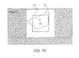
- FIG. 7Ais a screen shot of a track frame and respective target frame during a reduction procedure.
- FIG. 7Bis another screen shot a track frame and respective target frame during a reduction procedure.
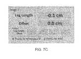
- FIG. 7Cis a screen shot displaying changes in leg length and offset after a reduction procedure.
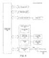
- FIG. 8is a schematic drawing of a computer system used to implement the methods presented.
- Matching Coordinate Systemis intended to generally include coordinate systems having parallel or collinear positional axes.
- the coordinate systems of the broach“matches” the coordinate system of the femur if the broach is aligned and positioned such that the positional axes of the broach are collinear or parallel to the positional axes of the femur.
- Positional Relationshipor “Relative Position”: The terms “positional relationship” or “relative position” generally refer to a rigid-body transformation between coordinate systems. In Cartesian space, the rigid-body transformation consists of six degrees-of-freedom (DOF): 3-DOF for translational position and 3-DOF for rotational (or orientation) position. In general, the terms “positional relationship” or “relative position” encompass one through six DOF. The number of DOF of a positional relationship may be explicitly stated (e.g., 2-DOF), or implied by the context (e.g., 3-DOF are generally used to describe orientation). For example, in some instances, positional relationship is determined by first determining the 6-DOF positioning, then extracting the desired positional information described by less than 6-DOF.
- DOFdegrees-of-freedom
- Registeror “Registration”: The terms “register” or “registration” generally refer to the act of determining a relative position between an object (e.g., pelvis, femur, instrument) and a respective sensor unit.
- objecte.g., pelvis, femur, instrument
- a sensor unitis broadly defined as any system component that includes at least a receiver or reader unit and/or a beacon or emitter unit.
- a receiver or reader unitis an example of a “sensor unit.”
- a beacon or emitterwhich is capable of being sensed by an optical reader, is another example of a “sensor unit.”
- Other examples of sensor unitsare presented in co-pending U.S. patent application Ser. No. 13/328,997, which has been incorporated by reference herein.
- Hip replacement surgeryinvolves replacing an existing joint with artificial prosthetic components.
- Examples of common joint replacementsinclude hip replacements and knee replacements.
- Hip replacementmay be segmented into three types: primary, revision, and resurfacing.
- Primary hip replacementalso called Total Hip Arthroplasty (THA)
- TAATotal Hip Arthroplasty
- an artificial canalis created in the proximal medullary region of the femur, and a metal femoral prosthesis is inserted into the femoral medullary canal.
- An acetabular component or implantis then inserted in the enlarged acetabular space.
- Hip resurfacinglike THA, involves the surgical removal of the acetabular cartilage and subchondral bone, and the subsequent insertion of an acetabular prosthetic. Unlike THA, resurfacing does not involve the excision of the femoral head, but rather covering the existing femoral head with a prosthetic cap, which mates with the acetabular prosthetic. Revision hip surgery is typically performed when an artificial hip joint fails. Revision hip surgery typically involves the replacement of one or more of the failed artificial prosthetic components.
- FIG. 1is a sectional view of a native hip joint 100 .
- the hip joint 100includes an acetabulum 102 (or socket) in the pelvic bone 104 , which is lined with acetabular cartilage 106 .
- the femoral head 108at the upper end of the femur 110 , is received in the acetabulum 102 .
- FIG. 2is a sectional view of a hip joint 200 after THA.
- the femur 210is first dislocated from the hip joint 200 .
- the acetabulum 202is then reamed out, and an acetabular component or implant 220 is attached to the acetabulum 202 .
- the femoral head of the femur 210is also removed.
- the femur 210is opened out, and a stem component 211 , referred to as the femoral component or femoral implant, is inserted into a canal created within the femur 210 .
- a ball component 208is then attached to the stem component 211 , to mate with the acetabular implant 220 .
- a reduction procedureis then performed to return the femur 210 to its proper position, with the ball component 208 set within the acetabular implant 220 .
- FIGS. 3A and 3Bare provided to illustrate pre-dislocation and post-reduction leg length and offset. More specifically, FIGS. 3A and 3B illustrate a hip joint 300 a before THA ( FIG.
- the original (i.e., pre-dislocation) leg length 305 a and offset 307 aare components of the vector between a landmark (or reference location) 301 on the pelvis 304 and a landmark 303 on the femur 310 .
- the resulting leg length 305 b and offset 307 bare components of the vector between the same landmarks (i.e., landmark 301 on the pelvis 304 , and landmark 303 on the femur 310 ).
- the original leg length 305 a and offset 307 amay be measured using a pre-operative scan (e.g., X-ray, CT scan, and MRI), as well as the original femoral center of rotation (COR) 308 a .
- a desired change in leg length and offsetmay be calculated based on a desired resulting leg length 305 b and offset 307 b , the original leg length 305 a and offset 307 a , the resulting COR 308 b , as well as the dimensions of the femoral implant.
- pre- and post-operative scans, as well as other known mechanical instrumentationmay be cumbersome and ineffective for determining leg length and offset intra-operatively.
- the systems and methods presented belowaid a surgeon in achieving a desired resulting leg length and offset by monitoring the leg length and offset during surgery, using sensor units attached to the pelvis and femur, and conveying a change in leg length and offset in a meaningful way.
- the systems and methods presentedmay also be used to determine and convey the pre- and post-operative femoral COR position, including the anterior-posterior change of the femoral COR position.
- Example embodimentsgenerally include placing a sensor unit on the pelvis, and a sensor unit on the femur.
- the sensor unitsare used to measure a pre-dislocation positional relationship between the pelvis and the femur in six degrees-of-freedom (DOF).
- positional relationshipimplies determining the positioning between two rigid bodies and their corresponding coordinate systems, neither of the rigid bodies being considered fixed to a global coordinate system.
- the sensor unitsmay be used to measure 3-DOF of position and 3-DOF of orientation.
- the sensor unitsare used to track and compare the positional relationship between the pelvis and the femur, before and after surgery. Any post-reduction change in positional relationship can be conveyed as changes in leg length and offset. To do so, the femoral coordinate system is registered, prior to reduction, but post-dislocation.
- Femoral registrationis typically performed by coupling a sensor unit to a registration tool (e.g., a surgical broach), and coupling the registration tool to the femur (e.g., inserting the broach into the femur).
- a registration toole.g., a surgical broach
- the registration toolis coupled to the femur
- a measurement between the sensor unit on the registration tool and the sensor unit on the femurcan “teach” the system the femoral coordinate system, which in turn teaches the system the directions of leg length and offset.
- the systems and methods presented hereinare distinctly different from traditional computer-assisted surgical systems that require: 1) registrations of multiple anatomical structures (e.g., pelvic registration and femoral registration); 2) markers positioned on respective anatomical structures; and 3) fixed stereoscopic camera units stationed within the operating room to monitor the movements of the markers throughout the surgery. Because the systems and methods presented measure positional relationships between sensor units mounted directly to the anatomical structures, and perform a femoral registration to identify the relative position between a femur sensor and the femur, accurate and real-time calculations can be performed without the use of pelvic registrations and/or fixed capital equipment stationed within the operating room.
- pelvic registrationis one of the biggest barriers to adoption of traditional navigation systems for hip arthroplasty. Pelvic registration is typically time consuming and/or inaccurate.
- the systems and methods presented hereinemploy a femoral registration, and associated femoral registration tool (e.g., broach and broach sensor), to overcome the disadvantages of traditional navigation systems that require pelvic registration and/or stereoscopic camera units.
- femoral registration with a femoral registration toolonly requires one registration measurement, instead of the at least three registration measurements required in a pelvic registration.
- Femoral registrationcan also be performed with existing surgical tools (e.g., broach), which are designed to mate with, and match orientations with, the femur.
- pelvic registrationrequires a “mapping” of the pelvis with a stylus/pointer tool.
- femoral registrationis more accurate because the femoral registration tool (e.g., broach) matches the anatomy of the femur and the final implant position; whereas the plane of the pelvis (e.g., anterior pelvic plane) is an arbitrary reference plane subject to inaccuracies in mapping to actual patient anatomy.
- femoral registration using existing surgical toolse.g., broach
- the systems and methods presentedcan be used to significantly reduce the complexities and capital expenditures of hip replacement surgeries (as well as other joint replacement surgeries). Further, the systems and methods presented may be used in a novel computer navigation system for performing joint replacement surgery.
- a navigation systememploying sensor units mounted directly onto anatomical structures, negates the need for fixed capital equipment stationed within the operating room.
- Such a navigation systemalso overcomes many of the drawbacks of traditional navigation systems. For example, such a navigation system does not require the large capital expenses of traditional navigation systems; avoids line-of-sight complications; and typically tracks only one object at a time, thus reducing computational complexity and facilitating greater robustness.
- FIGS. 4-6depict an exemplary embodiment of a hip replacement surgery employing the systems and methods disclosed herein. More specifically, FIG. 4 is a pre-dislocation side view of a patient's pelvis, with a sensor unit attached thereto, and a femur having a sensor unit attached thereto.
- FIG. 5is a cross-sectional view of a patient's femur, post-dislocation, having a broach inserted therein, in order to perform a femoral registration.
- FIG. 6is a side view of a patient's pelvis, having a sensor unit attached thereto, and a patient's femur having a sensor unit attached thereto, during a reduction procedure.
- a patient's pelvis 404 and femur 410are illustrated.
- the surgical woundpartly exposes the femur 410 and part of the greater trochanter 409 .
- a femur sensor unit 425is coupled to the femur 410
- a pelvis sensor unit 430is coupled to the pelvis 404 .
- the sensor unit 425is coupled to the femur 410 using a pin or bone screw 421 proximate the greater trochanter 409 .
- the sensor unit 425is positioned so that it lies along either the mechanical or anatomical femoral axis (e.g., it may be percutaneously coupled near the distal femur).
- the pelvis sensor unit 430is coupled to the pelvis 404 using a pin or bone screw 431 .
- the sensor units 425 , 430measure the positional relationship between one another, which is then translated to the positional relationship between the femur 410 and the pelvis 404 . More specifically, the sensor units 425 , 430 measure up to 6-DOF between one another (e.g., roll, pitch, yaw, and three translational distances).
- the information measured by the femur sensor unit 425 and the pelvis 430is transmitted to a computing device (e.g., computer 690 of FIG. 6 ), and contains enough information to determine the relative positioning of the sensor units, and therefore the relative positioning of the femur 410 with respect to the pelvis 404 .
- a computing devicee.g., computer 690 of FIG. 6
- This informationin conjunction with information regarding the femoral registration (discussed below), may be measured pre-dislocation, during a reduction procedure, and post-reduction. A comparison of the information measured pre-dislocation and post-reduction yields the actual changes in leg length and offset, as a result of the surgery. Similarly, the anterior-posterior change in femur position may be determined.
- FIG. 5is a cross-sectional view of a patient's femur 410 , post-dislocation, having a broach 580 inserted therein. More specifically, FIG. 5 illustrates the use of a broach 580 to perform a femoral registration. The femoral registration may thereby define a femoral coordinate system.
- the coordinate system associated with the broach 580consists of three axes, in which the dimensions of the broach can be described.
- the three axesmay include: one axis (e.g., x-axis), which points down the length of the broach; another axis (e.g., y-axis), which is perpendicular to the x-axis, and points along the offset dimension of the broach; and a third axis (e.g., z-axis), which perpendicular to both the x-axis and the y-axis.
- the coordinate system for the femurconsists of three axes, in which the dimensions of the femur can be described.
- the broach 580may be positioned within the femur such that the coordinate system of the broach matches the coordinate system of the femur.
- the broach 580may be positioned within the femur 410 such that the positional axes of the broach are collinear or otherwise parallel to the positional axes of the femur.
- the orientation between the broach 580 and the femur 410may also be defined by three degrees of rotation.
- the broach 580is oriented to match the orientation of the femur 410 .
- a broach sensor unit 540is coupled to the handle 582 of the broach 580 .
- sensor unit 425is activated to measure a positional relationship between the broach sensor unit 540 and the femur sensor unit 425 .
- Such positional relationshipis used to register the femur 410 .
- Registration of the femur 410is used to relate the femur to a reference frame, which in this case is the femur sensor unit 425 .
- the femoral registrationis performed by measuring 3-DOF of orientation (e.g., roll, pitch, and yaw) between the femur sensor unit 425 and the broach sensor unit 540 . While FIG.
- the broach 580serving as an interface with the femur 410
- the coordinate system of the broach 580preferably matches with a coordinate system of a femoral implant (i.e., the stem component 211 , of FIG. 2 , matches the broach stem 581 ).
- a modified femoral implantwhich includes an implant sensor, can be used in place of the broach 580 to perform the femoral registration.
- the pelvis sensor unit 430may be momentarily detached from the pelvis 404 and coupled to the broach 580 to perform the femoral registration.
- FIG. 6is a side view of a patient's pelvis 404 , having a sensor unit 430 attached thereto, and the patient's femur 410 having a sensor unit 425 attached thereto, during a reduction procedure.
- FIG. 6also shows a corresponding computer system 690 conveying a track frame 692 , target frame 691 , and leg length 693 and offset 694 changes. More specifically, FIG. 6 shows the artificial joint reduced (or assembled) after the implantation of the acetabular prosthetic 220 and the femoral prosthetic 211 .
- the positional relationship between the femur sensor unit 425 and the pelvis sensor unit 430can be measured, in real-time or proximate real-time, and transmitted wirelessly (or via wired communication) to computer system 690 .
- a processor within computer system 690uses the pre-dislocation positional relationship, femoral registration, and real-time positional relationship between the femur sensor unit and the pelvis sensor unit to display a target frame 691 and a tracking frame 692 .
- target frame 691depicts the original orientation (e.g., the pre-dislocation measurements of the original roll, pitch, and yaw) between the femur 410 and the pelvis 404 (or between the femur sensor unit 425 and the pelvis sensor unit 430 ).
- FIG. 7Ais a screen shot of a track frame 692 and respective target frame 691 during a reduction procedure. As shown in FIG. 7A , the track frame 692 is poorly aligned with the target frame 691 .
- FIG. 7Bis another screen shot the track frame 692 and respective target frame 691 , showing the track frame closely aligned with the target frame.
- Such depictionindicates to the surgeon that the reduction orientation of the femur 410 is approximating the pre-dislocation orientation of the femur.
- both the track frame 692 and the target frame 691are in complete alignment.
- the processorthen calculates and conveys a post-reduction change in leg length and offset, as shown in FIG. 7C .
- the processorwhen the femur 410 is orientated such that the track frame 692 matches the target frame 691 , the processor: (1) measures up to three translational distances between the pelvis sensor unit 430 and the femur sensor unit 425 ; (2) calculates the differences between the pre-dislocation and post-reduction translational distances; and (3) displays the change in leg length and change in offset between the pelvis 404 and the femur 410 based on the calculated differences in distance and the reference frame obtained during the femoral registration.
- the processorconverts or expresses differences in distance into the femoral coordinate system based on the femoral registration. While in the embodiment shown, the processor provides graphical and/or numerical displays, alternative embodiments include the use of any other audio/visual depiction or expression of the relevant information.
- a system for performing a computer-assisted hip replacement surgeryincludes: (1) a pelvis sensor unit configured to be coupled to a patient's pelvis; (2) a broach sensor unit configured to be coupled to a broach; (3) a femur sensor unit configured to be coupled to the patient's femur; and (4) a computer-readable storage medium having instructions executable, by at least one processing device, that when executed cause the processing device to perform functions that assist a physician during a hip replacement surgery.
- the processor-executable instructionswhen executed prior to a dislocation of the femur from the pelvis, wherein the pelvis sensor unit is coupled to the pelvis and the femur sensor unit is coupled to the femur, cause the processing device to measure a pre-dislocation positional relationship between the pelvis sensor unit and the femur sensor unit. Further, when executed after the dislocation of the femur from the pelvis, wherein the broach sensor unit is coupled to the broach, the femur sensor unit is coupled to the femur, and the broach is inserted within the femur, cause the processing device to perform a femoral registration by measuring an orientation between the broach sensor unit and the femur sensor unit.
- the processing devicewhen executed during a reduction procedure, wherein the pelvis sensor unit is coupled to the pelvis and the femur sensor unit is coupled to the femur, cause the processing device to display a fixed target frame and a track frame, wherein the track frame depicts a reduction orientation between the femur sensor unit and the pelvis sensor unit.
- the processing devicewhen executed after the femur has been positioned such that the track frame matches the target frame, cause the processing device to (1) measure a post-reduction translational distance between the pelvis sensor unit and the femur sensor unit and (2) calculate and display a change in leg length and a change in offset based the pre-dislocation positional relationship and the femoral registration.
- the computer-readable storage mediummay further includes instructions, which when executed, cause the processing device to calculate and display a change in anterior-posterior femur position based the pre-dislocation positional relationship and the femoral registration.
- the pre-dislocation positional relationshipmay include a translational component and an orientation component.
- the fixed target framemay depict the pre-dislocation orientation.
- the pre-dislocation positional relationshipmay be defined by roll, pitch, yaw, and three perpendicular translational distances between the pelvis sensor unit relative to the femur sensor unit.
- the fixed target framemay depict the pre-dislocation roll, pitch, and yaw.
- the femoral registrationmay thereby define a femoral coordinate system.
- a coordinate system of the broachmatches a coordinate system of the femur, such that the broach coordinate system is used to define the femoral coordinate.
- the orientation between the broach sensor unit and the femur sensor unitmay be defined by three degrees of rotation.
- the broachmay be aligned and positioned within the femur such that the positional axes of the broach are collinear or parallel to the positional axes of the femur.
- the femoral coordinate systemmay be defined in multiple ways, and alternative embodiments may call for alternative definitions of the femoral coordinate system.
- the femur sensor unitincludes an optical reader
- the pelvis sensor unit and the broach sensor unitinclude a beacon
- the pelvis sensor unit and the broach sensor unitmay include an optical reader
- the femur sensor unitmay include a beacon
- a system for performing hip replacement surgerycomprising: (a) means for measuring a pre-dislocation positional relationship between a patient's pelvis and the patient's femur; (b) means for performing a registration of the femur; (c) means for tracking the position of the femur, with respect to the pelvis, during a reduction procedure; (d) means for displaying the position of the femur, relative to the pelvis, during the reduction procedure; (e) means for calculating change in leg length, offset, and/or anterior-posterior position of the femur post-reduction; and/or (f) means for conveying the change in leg length, offset, and/or anterior-posterior position of the femur post-reduction.
- a method for performing a hip replacement surgerycomprising: (a) measuring a pre-dislocation positional relationship between a femur sensor unit coupled to the patient's femur and a pelvis sensor unit coupled to the patient's pelvis; (b) performing a post-dislocation femoral registration by measuring an orientation between the femur sensor unit and a broach sensor unit coupled to a broach inserted within the patient's femur; (c) measuring an orientation between the femur sensor unit and the pelvis sensor unit during a reduction procedure; and (d) calculating a change in leg length and a change in offset, based on the pre-dislocation positional relationship and the femoral registration.
- the methodmay further include (e) conveying the change in leg length and the change in offset.
- a method for performing a hip replacement surgerycomprising: (a) measuring a pre-dislocation translational position and orientation between a pelvis sensor unit coupled to a patient's pelvis and a femur sensor unit coupled to the patient's femur; (b) registering the femur after the femur has been dislocated from the pelvis; (c) displaying a graphic mapping the pre-dislocation orientation against a real-time orientation between the pelvis sensor unit and the femur sensor unit, during a reduction procedure; and (d) calculating a change in leg length and a change in offset, after the reduction procedure, based on the pre-dislocation translational position and the registration of the femur.
- the methodmay further include (e) conveying the change in leg length and the change in offset.
- the femurmay be registered by measuring an orientation between the femur sensor unit and a registration sensor unit coupled to a registration tool.
- the femurmay alternatively be registered by measuring an orientation between the femur sensor unit and a broach sensor unit coupled to a broach inserted within the patient's femur.
- a method or performing a hip replacement surgerycomprising: (a) measuring a pre-dislocation leg length and offset between a patient's pelvis and the patient's femur; (b) registering the femur after the femur has been dislocated from the pelvis; (c) tracking the position of the femur relative to the pelvis during a reduction procedure; and (d) calculating a change in leg length and a change in offset, after the reduction procedure, based on the registration of the femur and the pre-dislocation leg length and offset measurement.
- the methodmay further include (e) conveying the change in leg length and the change in offset.
- the femurmay be registered by measuring an orientation between the femur and a registration tool.
- data communication between the system components of the present inventionis accomplished over a network consisting of electronic devices connected either physically or wirelessly, wherein data is transmitted from one device to another.
- Such devicese.g., end-user devices
- Such devicesmay include, but are not limited to: a desktop computer, a laptop computer, a handheld device or PDA, a cellular telephone, a set top box, an television system, a mobile device or tablet, or systems equivalent thereto.
- Exemplary networksinclude a Local Area Network, a Wide Area Network, an organizational intranet, the Internet, or networks equivalent thereto.
- FIG. 8is a schematic drawing of a computer system 800 used to implement the methods presented above.
- Computer system 800includes one or more processors, such as processor 804 .
- the processor 804is connected to a communication infrastructure 806 (e.g., a communications bus, cross-over bar, or network).
- Computer system 800can include a display interface 802 that forwards graphics, text, and other data from the communication infrastructure 806 (or from a frame buffer not shown) for display on a local or remote display unit 830 .
- Computer system 800also includes a main memory 808 , such as random access memory (RAM), and may also include a secondary memory 810 .
- the secondary memory 810may include, for example, a hard disk drive 812 and/or a removable storage drive 814 , representing a floppy disk drive, a magnetic tape drive, an optical disk drive, flash memory device, etc.
- the removable storage drive 814reads from and/or writes to a removable storage unit 818 .
- Removable storage unit 818represents a floppy disk, magnetic tape, optical disk, flash memory device, etc., which is read by and written to by removable storage drive 814 .
- the removable storage unit 818includes a computer usable storage medium having stored therein computer software, instructions, and/or data.
- secondary memory 810may include other similar devices for allowing computer programs or other instructions to be loaded into computer system 800 .
- Such devicesmay include, for example, a removable storage unit 822 and an interface 820 .
- Examples of suchmay include a program cartridge and cartridge interface (such as that found in video game devices), a removable memory chip (such as an erasable programmable read only memory (EPROM), or programmable read only memory (PROM)) and associated socket, and other removable storage units 822 and interfaces 820 , which allow computer software, instructions, and/or data to be transferred from the removable storage unit 822 to computer system 800 .
- EPROMerasable programmable read only memory
- PROMprogrammable read only memory
- Computer system 800may also include a communications interface 824 .
- Communications interface 824allows computer software, instructions, and/or data to be transferred between computer system 800 and external devices.
- Examples of communications interface 824may include a modem, a network interface (such as an Ethernet card), a communications port, a Personal Computer Memory Card International Association (PCMCIA) slot and card, etc.
- Software and data transferred via communications interface 824are in the form of signals 828 which may be electronic, electromagnetic, optical or other signals capable of being received by communications interface 824 .
- These signals 828are provided to communications interface 824 via a communications path (e.g., channel) 826 .
- This channel 826carries signals 828 and may be implemented using wire or cable, fiber optics, a telephone line, a cellular link, a radio frequency (RF) link, a wireless communication link, and other communications channels.
- RFradio frequency
- computer-readable storage mediumIn this document, the terms “computer-readable storage medium,” “computer program medium,” and “computer usable medium” are used to generally refer to media such as removable storage drive 814 , removable storage units 818 , 822 , data transmitted via communications interface 824 , and/or a hard disk installed in hard disk drive 812 .
- These computer program productsprovide computer software, instructions, and/or data to computer system 800 .
- These computer program productsalso serve to transform a general purpose computer into a special purpose computer programmed to perform particular functions, pursuant to instructions from the computer program products/software. Embodiments of the present invention are directed to such computer program products.
- Computer programsare stored in main memory 808 and/or secondary memory 810 . Computer programs may also be received via communications interface 824 . Such computer programs, when executed, enable the computer system 800 to perform the features of the present invention, as discussed herein. In particular, the computer programs, when executed, enable the processor 804 to perform the features of the presented methods. Accordingly, such computer programs represent controllers of the computer system 800 . Where appropriate, the processor 804 , associated components, and equivalent systems and sub-systems thus serve as “means for” performing selected operations and functions. Such “means for” performing selected operations and functions also serve to transform a general purpose computer into a special purpose computer programmed to perform said selected operations and functions.
- the softwaremay be stored in a computer program product and loaded into computer system 800 using removable storage drive 814 , interface 820 , hard drive 812 , communications interface 824 , or equivalents thereof.
- the control logicwhen executed by the processor 804 , causes the processor 804 to perform the functions and methods described herein.
- the methodsare implemented primarily in hardware using, for example, hardware components such as application specific integrated circuits (ASICs). Implementation of the hardware state machine so as to perform the functions and methods described herein will be apparent to persons skilled in the relevant art(s). In yet another embodiment, the methods are implemented using a combination of both hardware and software.
- ASICsapplication specific integrated circuits
- Embodiments of the inventionmay also be implemented as instructions stored on a machine-readable medium, which may be read and executed by one or more processors.
- a machine-readable mediummay include any mechanism for storing or transmitting information in a form readable by a machine (e.g., a computing device).
- a machine-readable mediummay include read only memory (ROM); random access memory (RAM); magnetic disk storage media; optical storage media; flash memory devices; electrical, optical, acoustical or other forms of propagated signals (e.g., carrier waves, infrared signals, digital signals, etc.), and others.
- firmware, software, routines, instructionsmay be described herein as performing certain actions. However, it should be appreciated that such descriptions are merely for convenience and that such actions in fact result from computing devices, processors, controllers, or other devices executing firmware, software, routines, instructions, etc.
- a computer-readable storage mediumfor performing a hip replacement surgery, comprising instructions executable by at least one processing device that, when executed, cause the processing device to: (a) measure a pre-dislocation positional relationship between a femur sensor unit coupled to the patient's femur and a pelvis sensor unit coupled to the patient's pelvis; (b) perform a post-dislocation femoral registration by measuring an orientation between the femur sensor unit and a broach sensor unit coupled to a broach inserted within the patient's femur; (c) measure an orientation between the femur sensor unit and the pelvis sensor unit during a reduction procedure, and (d) calculate a change in leg length and a change in offset, based on the pre-dislocation positional relationship and the femoral registration.
- the computer-readable storage mediummay, further comprise instructions executable by at least one processing device that, when executed, cause the processing device to (e) convey the change in leg length and the change in
- a computer-readable storage mediumfor performing a hip replacement surgery, comprising instructions executable by at least one processing device that, when executed, cause the processing device to: (a) measure a pre-dislocation translational position and orientation between a pelvis sensor unit coupled to a patient's pelvis and a femur sensor unit coupled to the patient's femur; (b) register the femur after the femur has been dislocated from the pelvis; (c) display a graphic mapping the pre-dislocation orientation against a real-time orientation between the pelvis sensor unit and the femur sensor unit, during a reduction procedure; and (d) calculate a change in leg length and a change in offset, after the reduction procedure, based on the pre-dislocation translational position and the registration of the femur.
- the computer-readable storage mediummay further comprise instructions executable by at least one processing device that, when executed, cause the processing device to (e) convey the change in leg length and the change in offset.
- a computer-readable storage mediumfor performing a hip replacement surgery, comprising instructions executable by at least one processing device that, when executed, cause the processing device to: (a) measure a pre-dislocation leg length and offset between a patient's pelvis and the patient's femur; (b) register the femur after the femur has been dislocated from the pelvis; (c) track the position of the femur relative to the pelvis during a reduction procedure; and (d) calculate a change in leg length and a change in offset, after the reduction procedure, based on the registration of the femur and the pre-dislocation leg length and offset measurement.
- the computer-readable storage mediummay further comprise instructions executable by at least one processing device that, when executed, cause the processing device to (e) convey the change in leg length and the change in offset.
Landscapes
- Health & Medical Sciences (AREA)
- Life Sciences & Earth Sciences (AREA)
- Biomedical Technology (AREA)
- Molecular Biology (AREA)
- Oral & Maxillofacial Surgery (AREA)
- Biophysics (AREA)
- Pathology (AREA)
- Engineering & Computer Science (AREA)
- Dentistry (AREA)
- Heart & Thoracic Surgery (AREA)
- Medical Informatics (AREA)
- Physics & Mathematics (AREA)
- Surgery (AREA)
- Animal Behavior & Ethology (AREA)
- General Health & Medical Sciences (AREA)
- Public Health (AREA)
- Veterinary Medicine (AREA)
- Prostheses (AREA)
- Surgical Instruments (AREA)
Abstract
Description
Claims (18)
Priority Applications (2)
| Application Number | Priority Date | Filing Date | Title |
|---|---|---|---|
| US13/445,777US9314188B2 (en) | 2012-04-12 | 2012-04-12 | Computer-assisted joint replacement surgery and navigation systems |
| PCT/CA2013/000351WO2013152436A1 (en) | 2012-04-12 | 2013-04-12 | Computer-assisted joint replacement surgery and navigation systems |
Applications Claiming Priority (1)
| Application Number | Priority Date | Filing Date | Title |
|---|---|---|---|
| US13/445,777US9314188B2 (en) | 2012-04-12 | 2012-04-12 | Computer-assisted joint replacement surgery and navigation systems |
Publications (2)
| Publication Number | Publication Date |
|---|---|
| US20130274633A1 US20130274633A1 (en) | 2013-10-17 |
| US9314188B2true US9314188B2 (en) | 2016-04-19 |
Family
ID=49325719
Family Applications (1)
| Application Number | Title | Priority Date | Filing Date |
|---|---|---|---|
| US13/445,777Active2033-07-22US9314188B2 (en) | 2012-04-12 | 2012-04-12 | Computer-assisted joint replacement surgery and navigation systems |
Country Status (2)
| Country | Link |
|---|---|
| US (1) | US9314188B2 (en) |
| WO (1) | WO2013152436A1 (en) |
Cited By (7)
| Publication number | Priority date | Publication date | Assignee | Title |
|---|---|---|---|---|
| US20140218366A1 (en)* | 2011-06-28 | 2014-08-07 | Scopis Gmbh | Method and device for displaying an object |
| US20150216541A1 (en)* | 2014-02-03 | 2015-08-06 | Arthrex, Inc. | Pointing device and drilling tool |
| US20160287358A1 (en)* | 2012-02-06 | 2016-10-06 | A.Tron3D Gmbh | Device for detecting the three-dimensional geometry of objects and method for the operation thereof |
| US11166781B2 (en) | 2018-04-23 | 2021-11-09 | Mako Surgical Corp. | System, method and software program for aiding in positioning of a camera relative to objects in a surgical environment |
| US11771569B2 (en) | 2018-03-30 | 2023-10-03 | Regents Of The University Of Michigan | System and method for aligning hip replacement prostheses |
| US20240217115A1 (en)* | 2022-12-28 | 2024-07-04 | Kawasaki Jukogyo Kabushiki Kaisha | Robotic surgical system and method for controlling robotic surgical system |
| US12441001B2 (en)* | 2022-12-28 | 2025-10-14 | Kawasaki Jukogyo Kabushiki Kaisha | Robotic surgical system and method for controlling robotic surgical system |
Families Citing this family (31)
| Publication number | Priority date | Publication date | Assignee | Title |
|---|---|---|---|---|
| WO2004112610A2 (en) | 2003-06-09 | 2004-12-29 | Vitruvian Orthopaedics, Llc | Surgical orientation device and method |
| US7559931B2 (en) | 2003-06-09 | 2009-07-14 | OrthAlign, Inc. | Surgical orientation system and method |
| AU2009273863B2 (en) | 2008-07-24 | 2014-12-18 | OrthAlign, Inc. | Systems and methods for joint replacement |
| AU2009291743B2 (en) | 2008-09-10 | 2015-02-05 | Orthalign, Inc | Hip surgery systems and methods |
| US8588892B2 (en) | 2008-12-02 | 2013-11-19 | Avenir Medical Inc. | Method and system for aligning a prosthesis during surgery using active sensors |
| US10869771B2 (en) | 2009-07-24 | 2020-12-22 | OrthAlign, Inc. | Systems and methods for joint replacement |
| US8118815B2 (en) | 2009-07-24 | 2012-02-21 | OrthAlign, Inc. | Systems and methods for joint replacement |
| AU2011341678B2 (en) | 2010-01-21 | 2014-12-11 | OrthAlign, Inc. | Systems and methods for joint replacement |
| KR102072870B1 (en) | 2011-09-29 | 2020-02-03 | 알쓰로메다, 인코포레이티드 | system and method for precise prosthesis positioning in hip arthroplasty |
| US9314188B2 (en) | 2012-04-12 | 2016-04-19 | Intellijoint Surgical Inc. | Computer-assisted joint replacement surgery and navigation systems |
| US9549742B2 (en) | 2012-05-18 | 2017-01-24 | OrthAlign, Inc. | Devices and methods for knee arthroplasty |
| WO2013188960A1 (en) | 2012-06-20 | 2013-12-27 | Avenir Medical Inc. | Computer-assisted joint replacement surgery and patient-specific jig systems |
| US9649160B2 (en) | 2012-08-14 | 2017-05-16 | OrthAlign, Inc. | Hip replacement navigation system and method |
| US9585768B2 (en) | 2013-03-15 | 2017-03-07 | DePuy Synthes Products, Inc. | Acetabular cup prosthesis alignment system and method |
| US9247998B2 (en) | 2013-03-15 | 2016-02-02 | Intellijoint Surgical Inc. | System and method for intra-operative leg position measurement |
| CA2906152A1 (en) | 2013-03-15 | 2014-09-18 | Arthromeda, Inc. | Systems and methods for providing alignment in total knee arthroplasty |
| CN104068861B (en)* | 2014-07-03 | 2017-02-01 | 波纳维科(天津)医疗科技有限公司 | Thighbone length measurement device |
| US10413428B2 (en) | 2015-02-02 | 2019-09-17 | Orthosoft Inc. | Leg length calculation in computer-assisted surgery |
| US10363149B2 (en) | 2015-02-20 | 2019-07-30 | OrthAlign, Inc. | Hip replacement navigation system and method |
| EP3162316B1 (en)* | 2015-11-02 | 2023-01-11 | Medivation AG | A surgical instrument system |
| KR102578664B1 (en)* | 2016-05-11 | 2023-09-15 | 알쓰로메다, 인코포레이티드 | Patient-specific prosthesis alignment |
| US10660760B2 (en)* | 2016-11-02 | 2020-05-26 | Zimmer, Inc. | Device for sensing implant location and impingement |
| EP3554425B1 (en) | 2016-12-14 | 2024-03-13 | Zimmer, Inc. | Shoulder arthroplasty trial assembly comprising sensors |
| US11589926B2 (en) | 2017-01-04 | 2023-02-28 | Medivation Ag | Mobile surgical tracking system with an integrated fiducial marker for image guided interventions |
| EP3595554A4 (en) | 2017-03-14 | 2021-01-06 | OrthAlign, Inc. | Hip replacement navigation systems and methods |
| CA3056495A1 (en) | 2017-03-14 | 2018-09-20 | OrthAlign, Inc. | Soft tissue measurement & balancing systems and methods |
| WO2018202529A1 (en) | 2017-05-02 | 2018-11-08 | Medivation Ag | A surgical instrument system |
| US20210052348A1 (en) | 2018-01-22 | 2021-02-25 | Medivation Ag | An Augmented Reality Surgical Guidance System |
| CN113545847B (en)* | 2021-06-08 | 2022-07-26 | 北京天智航医疗科技股份有限公司 | Femoral head center positioning system and method |
| CN113744214B (en)* | 2021-08-24 | 2022-05-13 | 北京长木谷医疗科技有限公司 | Femoral stem placing device based on deep reinforcement learning and electronic equipment |
| CN116269952A (en)* | 2021-12-20 | 2023-06-23 | 北京天智航医疗科技股份有限公司 | Surgical upper computer and surgical system for measuring length of lower limb of hip joint replacement |
Citations (160)
| Publication number | Priority date | Publication date | Assignee | Title |
|---|---|---|---|---|
| US4994064A (en) | 1989-12-21 | 1991-02-19 | Aboczky Robert I | Instrument for orienting, inserting and impacting an acetabular cup prosthesis |
| US5122145A (en) | 1990-11-09 | 1992-06-16 | Fishbane Bruce M | Measuring device for use in total hip replacement |
| US5141512A (en) | 1989-08-28 | 1992-08-25 | Farmer Malcolm H | Alignment of hip joint sockets in hip joint replacement |
| FR2684287A1 (en) | 1991-12-03 | 1993-06-04 | Chagneau Francis | Device for controlling the positioning of the lower limb during an arthroplasty of the hip |
| US5227985A (en) | 1991-08-19 | 1993-07-13 | University Of Maryland | Computer vision system for position monitoring in three dimensions using non-coplanar light sources attached to a monitored object |
| US5249581A (en) | 1991-07-15 | 1993-10-05 | Horbal Mark T | Precision bone alignment |
| US5480439A (en) | 1991-02-13 | 1996-01-02 | Lunar Corporation | Method for periprosthetic bone mineral density measurement |
| US5611353A (en) | 1993-06-21 | 1997-03-18 | Osteonics Corp. | Method and apparatus for locating functional structures of the lower leg during knee surgery |
| US5700268A (en) | 1997-01-06 | 1997-12-23 | Zimmer, Inc. | Device for measuring leg length and off-set for a total hip replacement |
| US5772610A (en) | 1996-08-14 | 1998-06-30 | Liberty Mutual Group | Method and apparatus for dynamic and direct measurement of lumbar lordosis |
| US5807252A (en) | 1995-02-23 | 1998-09-15 | Aesculap Ag | Method and apparatus for determining the position of a body part |
| US5854843A (en) | 1995-06-07 | 1998-12-29 | The United States Of America As Represented By The Secretary Of The Air Force | Virtual navigator, and inertial angular measurement system |
| US5880976A (en) | 1997-02-21 | 1999-03-09 | Carnegie Mellon University | Apparatus and method for facilitating the implantation of artificial components in joints |
| US5956660A (en) | 1997-07-23 | 1999-09-21 | Analogic Corporation | Personal inertial surveying system |
| US5966827A (en) | 1996-05-06 | 1999-10-19 | Horvath; Laura | Method and apparatus for measuring pelvic symmetry |
| US6009189A (en) | 1996-08-16 | 1999-12-28 | Schaack; David F. | Apparatus and method for making accurate three-dimensional size measurements of inaccessible objects |
| US6061644A (en) | 1997-12-05 | 2000-05-09 | Northern Digital Incorporated | System for determining the spatial position and orientation of a body |
| US6161032A (en) | 1998-03-30 | 2000-12-12 | Biosense, Inc. | Three-axis coil sensor |
| US6395005B1 (en) | 2000-04-14 | 2002-05-28 | Howmedica Osteonics Corp. | Acetabular alignment apparatus and method |
| US20020077540A1 (en) | 2000-11-17 | 2002-06-20 | Kienzle Thomas C. | Enhanced graphic features for computer assisted surgery system |
| US20020087101A1 (en) | 2000-01-04 | 2002-07-04 | Barrick Earl Frederick | System and method for automatic shape registration and instrument tracking |
| US6450978B1 (en) | 1998-05-28 | 2002-09-17 | Orthosoft, Inc. | Interactive computer-assisted surgical system and method thereof |
| US20020198451A1 (en) | 2001-02-27 | 2002-12-26 | Carson Christopher P. | Surgical navigation systems and processes for high tibial osteotomy |
| US6529765B1 (en) | 1998-04-21 | 2003-03-04 | Neutar L.L.C. | Instrumented and actuated guidance fixture for sterotactic surgery |
| US20030069591A1 (en) | 2001-02-27 | 2003-04-10 | Carson Christopher Patrick | Computer assisted knee arthroplasty instrumentation, systems, and processes |
| US20030105470A1 (en) | 2001-11-14 | 2003-06-05 | White Michael R. | Apparatus and methods for making intraoperative orthopedic measurements |
| US20030153978A1 (en) | 2002-02-08 | 2003-08-14 | Whiteside Biomechanics, Inc. | Apparatus and method of ligament balancing and component fit check in total knee arthroplasty |
| US6607487B2 (en) | 2001-01-23 | 2003-08-19 | The Regents Of The University Of California | Ultrasound image guided acetabular implant orientation during total hip replacement |
| US20030163142A1 (en) | 1997-11-27 | 2003-08-28 | Yoav Paltieli | System and method for guiding the movements of a device to a target particularly for medical applications |
| US20030208296A1 (en) | 2002-05-03 | 2003-11-06 | Carnegie Mellon University | Methods and systems to control a shaping tool |
| US6711431B2 (en)* | 2002-02-13 | 2004-03-23 | Kinamed, Inc. | Non-imaging, computer assisted navigation system for hip replacement surgery |
| US6718194B2 (en)* | 2000-11-17 | 2004-04-06 | Ge Medical Systems Global Technology Company, Llc | Computer assisted intramedullary rod surgery system with enhanced features |
| US20040102792A1 (en) | 2002-08-09 | 2004-05-27 | Sarin Vineet Kumar | Non-imaging tracking tools and method for hip replacement surgery |
| US20040106861A1 (en) | 2002-12-03 | 2004-06-03 | Francois Leitner | Method of determining the position of the articular point of a joint |
| US20040143340A1 (en) | 2002-11-05 | 2004-07-22 | Gregor Tuma | Method and device for registering a femur implant |
| US20040147926A1 (en) | 2001-04-06 | 2004-07-29 | Iversen Bjorn Franc | Computer assisted insertion of an artificial hip joint |
| US20040230199A1 (en)* | 2002-10-04 | 2004-11-18 | Jansen Herbert Andre | Computer-assisted hip replacement surgery |
| US20040243148A1 (en) | 2003-04-08 | 2004-12-02 | Wasielewski Ray C. | Use of micro- and miniature position sensing devices for use in TKA and THA |
| US20040254586A1 (en) | 2003-04-02 | 2004-12-16 | Sarin Vineet Kumar | Pelvic plane locator and patient positioner |
| US20050015002A1 (en) | 2003-07-18 | 2005-01-20 | Dixon Gary S. | Integrated protocol for diagnosis, treatment, and prevention of bone mass degradation |
| US20050021044A1 (en) | 2003-06-09 | 2005-01-27 | Vitruvian Orthopaedics, Llc | Surgical orientation device and method |
| US20050049524A1 (en) | 2001-11-05 | 2005-03-03 | Christian Lefevre | Methods for selecting knee prosthesis elements and device therefor |
| US20050065617A1 (en) | 2003-09-05 | 2005-03-24 | Moctezuma De La Barrera Jose Luis | System and method of performing ball and socket joint arthroscopy |
| US20050149050A1 (en) | 2002-05-21 | 2005-07-07 | Jan Stifter | Arrangement and method for the intra-operative determination of the position of a joint replacement implant |
| US6925339B2 (en) | 2003-02-04 | 2005-08-02 | Zimmer Technology, Inc. | Implant registration device for surgical navigation system |
| US20050245820A1 (en) | 2004-04-28 | 2005-11-03 | Sarin Vineet K | Method and apparatus for verifying and correcting tracking of an anatomical structure during surgery |
| US20050251026A1 (en) | 2003-06-09 | 2005-11-10 | Vitruvian Orthopaedics, Llc | Surgical orientation system and method |
| US6978167B2 (en) | 2002-07-01 | 2005-12-20 | Claron Technology Inc. | Video pose tracking system and method |
| US20050288609A1 (en) | 2004-06-23 | 2005-12-29 | Warner Michael J | Method and apparatus for inducing and detecting ankle torsion |
| US20060004284A1 (en) | 2004-06-30 | 2006-01-05 | Frank Grunschlager | Method and system for generating three-dimensional model of part of a body from fluoroscopy image data and specific landmarks |
| US6988009B2 (en) | 2003-02-04 | 2006-01-17 | Zimmer Technology, Inc. | Implant registration device for surgical navigation system |
| US20060084889A1 (en) | 2004-09-02 | 2006-04-20 | Peter Drumm | Registering intraoperative scans |
| US20060089657A1 (en) | 2000-08-31 | 2006-04-27 | Holger Broers | Method and apparatus for finding the position of a mechanical axis of a limb |
| US20060095047A1 (en) | 2004-10-08 | 2006-05-04 | De La Barrera Jose Luis M | System and method for performing arthroplasty of a joint and tracking a plumb line plane |
| US20060155382A1 (en) | 2005-01-07 | 2006-07-13 | Orthopaedic Development, Llc. | Canulized prosthesis for total hip replacement surgery |
| US20060161052A1 (en) | 2004-12-08 | 2006-07-20 | Perception Raisonnement Action En Medecine | Computer assisted orthopaedic surgery system for ligament graft reconstruction |
| US20060189864A1 (en) | 2005-01-26 | 2006-08-24 | Francois Paradis | Computer-assisted hip joint resurfacing method and system |
| US20060190011A1 (en) | 2004-12-02 | 2006-08-24 | Michael Ries | Systems and methods for providing a reference plane for mounting an acetabular cup during a computer-aided surgery |
| WO2006109983A1 (en) | 2005-04-12 | 2006-10-19 | Korea Advanced Institute Of Science And Technology | Navigation system for hip replacement surgery having reference mechanism and method using the same |
| US7130676B2 (en) | 1998-08-20 | 2006-10-31 | Sofamor Danek Holdings, Inc. | Fluoroscopic image guided orthopaedic surgery system with intraoperative registration |
| WO2006128301A1 (en) | 2005-06-02 | 2006-12-07 | Orthosoft Inc. | Leg alignment for surgical parameter measurement in hip replacement surgery |
| US20070118139A1 (en) | 2005-10-14 | 2007-05-24 | Cuellar Alberto D | System and method for bone resection |
| WO2007084893A2 (en) | 2006-01-17 | 2007-07-26 | Stryker Corporation | Hybrid navigation system for tracking the position of body tissue |
| US20070179568A1 (en) | 2006-01-31 | 2007-08-02 | Sdgi Holdings, Inc. | Methods for detecting osteolytic conditions in the body |
| WO2007095248A2 (en) | 2006-02-10 | 2007-08-23 | Murphy Stephen B | System and method for facilitating hip surgery |
| US20070225731A1 (en) | 2006-03-23 | 2007-09-27 | Pierre Couture | Method and system for tracking tools in computer-assisted surgery |
| US20070239281A1 (en) | 2006-01-10 | 2007-10-11 | Brainlab Ab | Femur head center localization |
| US20070249967A1 (en) | 2006-03-21 | 2007-10-25 | Perception Raisonnement Action En Medecine | Computer-aided osteoplasty surgery system |
| US20070270686A1 (en) | 2006-05-03 | 2007-11-22 | Ritter Rogers C | Apparatus and methods for using inertial sensing to navigate a medical device |
| US7302355B2 (en) | 2005-05-20 | 2007-11-27 | Orthosoft Inc. | Method and apparatus for calibrating circular objects using a computer tracking system |
| US7314048B2 (en) | 2002-04-17 | 2008-01-01 | Orthosoft Inc. | CAS drill guide and drill tracking system |
| US20080027312A1 (en) | 2006-07-25 | 2008-01-31 | Robert Dick | Displaying object orientations on ball joints |
| US20080033442A1 (en) | 2006-08-03 | 2008-02-07 | Louis-Philippe Amiot | Computer-assisted surgery tools and system |
| US20080051910A1 (en) | 2006-08-08 | 2008-02-28 | Aesculap Ag & Co. Kg | Method and apparatus for positioning a bone prosthesis using a localization system |
| US20080077004A1 (en) | 2006-09-21 | 2008-03-27 | Stefan Henning | Pelvic registration device for medical navigation |
| US20080125785A1 (en) | 2006-09-25 | 2008-05-29 | Gursharan Singh Chana | Targeting Device |
| US20080132783A1 (en) | 2004-03-05 | 2008-06-05 | Ian Revie | Pelvis Registration Method and Apparatus |
| US20080146969A1 (en)* | 2006-12-15 | 2008-06-19 | Kurtz William B | Total joint replacement component positioning as predetermined distance from center of rotation of the joint using pinless navigation |
| US7392076B2 (en) | 2003-11-04 | 2008-06-24 | Stryker Leibinger Gmbh & Co. Kg | System and method of registering image data to intra-operatively digitized landmarks |
| US7400246B2 (en) | 2006-04-11 | 2008-07-15 | Russell Mark Breeding | Inertial Sensor Tracking System |
| US20080172055A1 (en) | 2005-01-17 | 2008-07-17 | Aesculap Ag & Co. Kg | Method for indicating the position and orientation of a surgical tool and apparatus for performing this method |
| US20080183104A1 (en) | 2002-09-24 | 2008-07-31 | Gregor Tuma | Device and method for determining the aperture angle of a joint |
| US7407054B2 (en) | 2002-12-30 | 2008-08-05 | Calypso Medical Technologies, Inc. | Packaged systems for implanting markers in a patient and methods for manufacturing and using such systems |
| US20080195109A1 (en) | 2007-02-13 | 2008-08-14 | Hunter Mark W | Navigated cut guide for total knee reconstruction |
| US7412777B2 (en) | 2005-05-20 | 2008-08-19 | Orthosoft Inc. | Method and apparatus for calibrating spherical objects using a computer system |
| US7419492B2 (en) | 2003-04-21 | 2008-09-02 | Korea Advanced Institute Of Science And Technology | T-shaped gauge and acetabular cup navigation system and acetabular cup aligning method using the same |
| US20080214960A1 (en) | 2005-06-17 | 2008-09-04 | Antony Hodgson | Method and Apparatus for Computer-Assisted Femoral Head Resurfacing |
| US20080228188A1 (en) | 2005-03-22 | 2008-09-18 | Alec Paul Birkbeck | Surgical guide |
| US7427272B2 (en) | 2003-07-15 | 2008-09-23 | Orthosoft Inc. | Method for locating the mechanical axis of a femur |
| US7431736B2 (en) | 2000-07-28 | 2008-10-07 | Depuy Products, Inc. | Device and method for positioning an eccentric humeral head of a humerus prosthesis for a shoulder arthroplasty |
| US20080249394A1 (en) | 2007-04-03 | 2008-10-09 | The Board Of Trustees Of The Leland Stanford Junior University | Method for improved rotational alignment in joint arthroplasty |
| US20080255584A1 (en) | 2005-04-09 | 2008-10-16 | David Beverland | Acetabular Cup Positioning |
| US20080269596A1 (en) | 2004-03-10 | 2008-10-30 | Ian Revie | Orthpaedic Monitoring Systems, Methods, Implants and Instruments |
| US20080294265A1 (en) | 2007-05-22 | 2008-11-27 | Blaine Warkentine | Navigated placement of pelvic implant based on combined anteversion by applying ranawat's sign or via arithmetic formula |
| WO2008151446A1 (en) | 2007-06-15 | 2008-12-18 | Orthosoft Inc. | Computer-assisted surgery system and method |
| US20080319313A1 (en) | 2007-06-22 | 2008-12-25 | Michel Boivin | Computer-assisted surgery system with user interface |
| US20090087050A1 (en) | 2007-08-16 | 2009-04-02 | Michael Gandyra | Device for determining the 3D coordinates of an object, in particular of a tooth |
| US20090099570A1 (en) | 2007-10-10 | 2009-04-16 | Francois Paradis | Hip replacement in computer-assisted surgery |
| US20090105714A1 (en) | 2007-10-17 | 2009-04-23 | Aesculap Ag | Method and apparatus for determining the angular position of an acetabulum in a pelvic bone |
| US20090125117A1 (en)* | 2007-11-14 | 2009-05-14 | Francois Paradis | Leg alignment and length measurement in hip replacement surgery |
| US20090143670A1 (en) | 2007-11-30 | 2009-06-04 | Daigneault Emmanuel | Optical tracking cas system |
| US20090163930A1 (en) | 2007-12-19 | 2009-06-25 | Ahmed Aoude | Calibration system of a computer-assisted surgery system |
| US20090209343A1 (en) | 2008-02-15 | 2009-08-20 | Eric Foxlin | Motion-tracking game controller |
| US7588571B2 (en) | 2005-03-18 | 2009-09-15 | Ron Anthon Olsen | Adjustable splint for osteosynthesis with modular joint |
| US20090248044A1 (en) | 2008-03-25 | 2009-10-01 | Orthosoft, Inc. | Method and system for planning/guiding alterations to a bone |
| US20090281545A1 (en) | 2008-03-05 | 2009-11-12 | Allston J. Stubbs | Method and Apparatus for Arthroscopic Assisted Arthroplasty of the Hip Joint |
| US20090289806A1 (en) | 2008-03-13 | 2009-11-26 | Thornberry Robert L | Computer-guided system for orienting the acetabular cup in the pelvis during total hip replacement surgery |
| US7634306B2 (en) | 2002-02-13 | 2009-12-15 | Kinamed, Inc. | Non-image, computer assisted navigation system for joint replacement surgery with modular implant system |
| US20090314925A1 (en) | 2008-06-18 | 2009-12-24 | Mako Surgical Corp. | Fiber optic tracking system and method for tracking |
| US20090316967A1 (en) | 2008-06-20 | 2009-12-24 | Universite De Bretagne Occidentale | Help system for implanting a hip prosthesis on an individual |
| US7657298B2 (en) | 2004-03-11 | 2010-02-02 | Stryker Leibinger Gmbh & Co. Kg | System, device, and method for determining a position of an object |
| US7668584B2 (en) | 2002-08-16 | 2010-02-23 | Orthosoft Inc. | Interface apparatus for passive tracking systems and method of use thereof |
| US20100063509A1 (en) | 2008-07-24 | 2010-03-11 | OrthAlign, Inc. | Systems and methods for joint replacement |
| WO2010030809A1 (en) | 2008-09-10 | 2010-03-18 | Orthalign, Inc | Hip surgery systems and methods |
| EP1563810B1 (en) | 2004-02-10 | 2010-03-31 | Tornier | Surgical apparatus for implanting a total hip prosthesis |
| US20100100011A1 (en)* | 2008-10-22 | 2010-04-22 | Martin Roche | System and Method for Orthopedic Alignment and Measurement |
| WO2010063117A1 (en) | 2008-12-02 | 2010-06-10 | Andre Novomir Hladio | Method and system for aligning a prosthesis during surgery using active sensors |
| US20100153081A1 (en) | 2008-12-11 | 2010-06-17 | Mako Surgical Corp. | Implant planning for multiple implant components using constraints |
| US7749223B2 (en)* | 2004-08-09 | 2010-07-06 | Howmedica Osteonics Corp. | Navigated femoral axis finder |
| US7753921B2 (en) | 2005-10-06 | 2010-07-13 | Aesculap Ag | Method and apparatus for determining the position of an object |
| US7769429B2 (en) | 2000-07-06 | 2010-08-03 | Ao Technology Ag | Method and device for impingement detection |
| US20100192961A1 (en) | 2007-11-08 | 2010-08-05 | Louis-Philippe Amiot | Trackable reference device for computer-assisted surgery |
| US20100261998A1 (en)* | 2007-11-19 | 2010-10-14 | Stiehl James B | Hip implant registration in computer assisted surgery |
| US20100268067A1 (en) | 2009-02-17 | 2010-10-21 | Inneroptic Technology Inc. | Systems, methods, apparatuses, and computer-readable media for image guided surgery |
| US7840256B2 (en) | 2005-06-27 | 2010-11-23 | Biomet Manufacturing Corporation | Image guided tracking array and method |
| US20100299101A1 (en) | 2006-01-24 | 2010-11-25 | Carnegie Mellon University | Method, Apparatus, And System For Computer-Aided Tracking, Navigation And Motion Teaching |
| US20100312247A1 (en) | 2009-06-05 | 2010-12-09 | Gregor Tuma | Tool attachment for medical applications |
| US7876942B2 (en) | 2006-03-30 | 2011-01-25 | Activiews Ltd. | System and method for optical position measurement and guidance of a rigid or semi-flexible tool to a target |
| US20110092858A1 (en) | 2008-02-29 | 2011-04-21 | Depuy International Ltd | Surgical apparatus and procedure |
| US7970190B2 (en) | 2006-09-01 | 2011-06-28 | Brainlab Ag | Method and device for determining the location of pelvic planes |
| US20110160572A1 (en) | 2009-12-31 | 2011-06-30 | Orthosensor | Disposable wand and sensor for orthopedic alignment |
| US7995280B2 (en) | 2004-12-01 | 2011-08-09 | Carl Zeiss Smt Gmbh | Projection exposure system, beam delivery system and method of generating a beam of light |
| US8000926B2 (en) | 2005-11-28 | 2011-08-16 | Orthosensor | Method and system for positional measurement using ultrasonic sensing |
| US20110213379A1 (en) | 2010-03-01 | 2011-09-01 | Stryker Trauma Gmbh | Computer assisted surgery system |
| US8034057B2 (en) | 2002-11-07 | 2011-10-11 | Penenberg Brad L | Apparatus for, and method of, preparing for and inserting hip joint prosthesis using computer guidance |
| US20110257653A1 (en) | 2010-04-14 | 2011-10-20 | Smith & Nephew, Inc. | Systems and Methods for Patient-Based Computer Assisted Surgical Procedures |
| US20110264009A1 (en) | 2008-02-29 | 2011-10-27 | Silesco Pty Ltd. | Orthopaedic Safety System |
| US20120029389A1 (en) | 2010-07-30 | 2012-02-02 | Louis-Philippe Amiot | Bone tracking with a gyroscope sensor in computer-assisted surgery |
| US20120053594A1 (en) | 2010-08-31 | 2012-03-01 | Benoit Pelletier | Tool and method for digital acquisition of a tibial mechanical axis |
| US20120065926A1 (en) | 2010-09-14 | 2012-03-15 | Samsung Electronics Co., Ltd | Integrated motion sensing apparatus |
| US8152726B2 (en) | 2006-07-21 | 2012-04-10 | Orthosoft Inc. | Non-invasive tracking of bones for surgery |
| US8165659B2 (en) | 2006-03-22 | 2012-04-24 | Garrett Sheffer | Modeling method and apparatus for use in surgical navigation |
| US8167823B2 (en) | 2009-03-24 | 2012-05-01 | Biomet Manufacturing Corp. | Method and apparatus for aligning and securing an implant relative to a patient |
| US8177850B2 (en) | 2006-06-19 | 2012-05-15 | iGO Technologies, Inc. | Joint placement methods and apparatuses |
| US20120143084A1 (en) | 2009-08-17 | 2012-06-07 | Moshe Shoham | Device for improving the accuracy of manual operations |
| US8202324B2 (en) | 2006-07-18 | 2012-06-19 | Zimmer, Inc. | Modular orthopaedic component case |
| US20120157887A1 (en) | 2010-12-17 | 2012-06-21 | Richard Tyler Fanson | Method and system for aligning a prosthesis during surgery |
| US20120209117A1 (en) | 2006-03-08 | 2012-08-16 | Orthosensor, Inc. | Surgical Measurement Apparatus and System |
| US20120232802A1 (en) | 2009-09-08 | 2012-09-13 | Brainlab Ag | Determining a plane of an anatomical body part |
| US20120323247A1 (en) | 2011-06-16 | 2012-12-20 | Smith & Nephew, Inc. | Surgical alignment using references |
| US8337426B2 (en) | 2009-03-24 | 2012-12-25 | Biomet Manufacturing Corp. | Method and apparatus for aligning and securing an implant relative to a patient |
| US8400312B2 (en) | 2006-10-10 | 2013-03-19 | Saga University | Operation assisting system |
| US8425557B2 (en) | 2004-04-22 | 2013-04-23 | Gmedelaware 2 Llc | Crossbar spinal prosthesis having a modular design and related implantation methods |
| US8467851B2 (en) | 2005-09-21 | 2013-06-18 | Medtronic Navigation, Inc. | Method and apparatus for positioning a reference frame |
| US8482606B2 (en) | 2006-08-02 | 2013-07-09 | Inneroptic Technology, Inc. | System and method of providing real-time dynamic imagery of a medical procedure site using multiple modalities |
| US8554307B2 (en) | 2010-04-12 | 2013-10-08 | Inneroptic Technology, Inc. | Image annotation in image-guided medical procedures |
| WO2013152436A1 (en) | 2012-04-12 | 2013-10-17 | Avenir Medical Inc. | Computer-assisted joint replacement surgery and navigation systems |
| US8641621B2 (en) | 2009-02-17 | 2014-02-04 | Inneroptic Technology, Inc. | Systems, methods, apparatuses, and computer-readable media for image management in image-guided medical procedures |
| US8657809B2 (en) | 2010-09-29 | 2014-02-25 | Stryker Leibinger Gmbh & Co., Kg | Surgical navigation system |
| US8670816B2 (en) | 2012-01-30 | 2014-03-11 | Inneroptic Technology, Inc. | Multiple medical device guidance |
- 2012
- 2012-04-12USUS13/445,777patent/US9314188B2/enactiveActive
- 2013
- 2013-04-12WOPCT/CA2013/000351patent/WO2013152436A1/enactiveApplication Filing
Patent Citations (189)
| Publication number | Priority date | Publication date | Assignee | Title |
|---|---|---|---|---|
| US5141512A (en) | 1989-08-28 | 1992-08-25 | Farmer Malcolm H | Alignment of hip joint sockets in hip joint replacement |
| US4994064A (en) | 1989-12-21 | 1991-02-19 | Aboczky Robert I | Instrument for orienting, inserting and impacting an acetabular cup prosthesis |
| US5122145A (en) | 1990-11-09 | 1992-06-16 | Fishbane Bruce M | Measuring device for use in total hip replacement |
| US5480439A (en) | 1991-02-13 | 1996-01-02 | Lunar Corporation | Method for periprosthetic bone mineral density measurement |
| US5249581A (en) | 1991-07-15 | 1993-10-05 | Horbal Mark T | Precision bone alignment |
| US5227985A (en) | 1991-08-19 | 1993-07-13 | University Of Maryland | Computer vision system for position monitoring in three dimensions using non-coplanar light sources attached to a monitored object |
| FR2684287A1 (en) | 1991-12-03 | 1993-06-04 | Chagneau Francis | Device for controlling the positioning of the lower limb during an arthroplasty of the hip |
| US5611353A (en) | 1993-06-21 | 1997-03-18 | Osteonics Corp. | Method and apparatus for locating functional structures of the lower leg during knee surgery |
| US5807252A (en) | 1995-02-23 | 1998-09-15 | Aesculap Ag | Method and apparatus for determining the position of a body part |
| US5854843A (en) | 1995-06-07 | 1998-12-29 | The United States Of America As Represented By The Secretary Of The Air Force | Virtual navigator, and inertial angular measurement system |
| US5966827A (en) | 1996-05-06 | 1999-10-19 | Horvath; Laura | Method and apparatus for measuring pelvic symmetry |
| US5772610A (en) | 1996-08-14 | 1998-06-30 | Liberty Mutual Group | Method and apparatus for dynamic and direct measurement of lumbar lordosis |
| US6009189A (en) | 1996-08-16 | 1999-12-28 | Schaack; David F. | Apparatus and method for making accurate three-dimensional size measurements of inaccessible objects |
| US5700268A (en) | 1997-01-06 | 1997-12-23 | Zimmer, Inc. | Device for measuring leg length and off-set for a total hip replacement |
| US5880976A (en) | 1997-02-21 | 1999-03-09 | Carnegie Mellon University | Apparatus and method for facilitating the implantation of artificial components in joints |
| US5956660A (en) | 1997-07-23 | 1999-09-21 | Analogic Corporation | Personal inertial surveying system |
| US20030163142A1 (en) | 1997-11-27 | 2003-08-28 | Yoav Paltieli | System and method for guiding the movements of a device to a target particularly for medical applications |
| US6061644A (en) | 1997-12-05 | 2000-05-09 | Northern Digital Incorporated | System for determining the spatial position and orientation of a body |
| US6161032A (en) | 1998-03-30 | 2000-12-12 | Biosense, Inc. | Three-axis coil sensor |
| US6529765B1 (en) | 1998-04-21 | 2003-03-04 | Neutar L.L.C. | Instrumented and actuated guidance fixture for sterotactic surgery |
| US6450978B1 (en) | 1998-05-28 | 2002-09-17 | Orthosoft, Inc. | Interactive computer-assisted surgical system and method thereof |
| US7130676B2 (en) | 1998-08-20 | 2006-10-31 | Sofamor Danek Holdings, Inc. | Fluoroscopic image guided orthopaedic surgery system with intraoperative registration |
| US20020087101A1 (en) | 2000-01-04 | 2002-07-04 | Barrick Earl Frederick | System and method for automatic shape registration and instrument tracking |
| US6395005B1 (en) | 2000-04-14 | 2002-05-28 | Howmedica Osteonics Corp. | Acetabular alignment apparatus and method |
| US7769429B2 (en) | 2000-07-06 | 2010-08-03 | Ao Technology Ag | Method and device for impingement detection |
| US7431736B2 (en) | 2000-07-28 | 2008-10-07 | Depuy Products, Inc. | Device and method for positioning an eccentric humeral head of a humerus prosthesis for a shoulder arthroplasty |
| US20060089657A1 (en) | 2000-08-31 | 2006-04-27 | Holger Broers | Method and apparatus for finding the position of a mechanical axis of a limb |
| US20020077540A1 (en) | 2000-11-17 | 2002-06-20 | Kienzle Thomas C. | Enhanced graphic features for computer assisted surgery system |
| US6917827B2 (en) | 2000-11-17 | 2005-07-12 | Ge Medical Systems Global Technology Company, Llc | Enhanced graphic features for computer assisted surgery system |
| US6718194B2 (en)* | 2000-11-17 | 2004-04-06 | Ge Medical Systems Global Technology Company, Llc | Computer assisted intramedullary rod surgery system with enhanced features |
| US6607487B2 (en) | 2001-01-23 | 2003-08-19 | The Regents Of The University Of California | Ultrasound image guided acetabular implant orientation during total hip replacement |
| US20020198451A1 (en) | 2001-02-27 | 2002-12-26 | Carson Christopher P. | Surgical navigation systems and processes for high tibial osteotomy |
| US20030069591A1 (en) | 2001-02-27 | 2003-04-10 | Carson Christopher Patrick | Computer assisted knee arthroplasty instrumentation, systems, and processes |
| US20040147926A1 (en) | 2001-04-06 | 2004-07-29 | Iversen Bjorn Franc | Computer assisted insertion of an artificial hip joint |
| US20050049524A1 (en) | 2001-11-05 | 2005-03-03 | Christian Lefevre | Methods for selecting knee prosthesis elements and device therefor |
| US7001346B2 (en) | 2001-11-14 | 2006-02-21 | Michael R. White | Apparatus and methods for making intraoperative orthopedic measurements |
| US20030105470A1 (en) | 2001-11-14 | 2003-06-05 | White Michael R. | Apparatus and methods for making intraoperative orthopedic measurements |
| US20030153978A1 (en) | 2002-02-08 | 2003-08-14 | Whiteside Biomechanics, Inc. | Apparatus and method of ligament balancing and component fit check in total knee arthroplasty |
| US7780681B2 (en)* | 2002-02-13 | 2010-08-24 | Kinamed, Inc. | Non-imaging, computer assisted navigation system for hip replacement surgery |
| US7634306B2 (en) | 2002-02-13 | 2009-12-15 | Kinamed, Inc. | Non-image, computer assisted navigation system for joint replacement surgery with modular implant system |
| US6711431B2 (en)* | 2002-02-13 | 2004-03-23 | Kinamed, Inc. | Non-imaging, computer assisted navigation system for hip replacement surgery |
| US7314048B2 (en) | 2002-04-17 | 2008-01-01 | Orthosoft Inc. | CAS drill guide and drill tracking system |
| US20030208296A1 (en) | 2002-05-03 | 2003-11-06 | Carnegie Mellon University | Methods and systems to control a shaping tool |
| US20050149050A1 (en) | 2002-05-21 | 2005-07-07 | Jan Stifter | Arrangement and method for the intra-operative determination of the position of a joint replacement implant |
| US6978167B2 (en) | 2002-07-01 | 2005-12-20 | Claron Technology Inc. | Video pose tracking system and method |
| US20040102792A1 (en) | 2002-08-09 | 2004-05-27 | Sarin Vineet Kumar | Non-imaging tracking tools and method for hip replacement surgery |
| US7668584B2 (en) | 2002-08-16 | 2010-02-23 | Orthosoft Inc. | Interface apparatus for passive tracking systems and method of use thereof |
| US20080183104A1 (en) | 2002-09-24 | 2008-07-31 | Gregor Tuma | Device and method for determining the aperture angle of a joint |
| US8308663B2 (en) | 2002-09-24 | 2012-11-13 | Brainlab Ag | Device and method for determining the aperture angle of a joint |
| US20040230199A1 (en)* | 2002-10-04 | 2004-11-18 | Jansen Herbert Andre | Computer-assisted hip replacement surgery |
| US7877131B2 (en) | 2002-10-04 | 2011-01-25 | Orthosoft Inc. | Method for providing pelvic orientation information in computer-assisted surgery |
| US20040143340A1 (en) | 2002-11-05 | 2004-07-22 | Gregor Tuma | Method and device for registering a femur implant |
| US8034057B2 (en) | 2002-11-07 | 2011-10-11 | Penenberg Brad L | Apparatus for, and method of, preparing for and inserting hip joint prosthesis using computer guidance |
| US20040106861A1 (en) | 2002-12-03 | 2004-06-03 | Francois Leitner | Method of determining the position of the articular point of a joint |
| US7407054B2 (en) | 2002-12-30 | 2008-08-05 | Calypso Medical Technologies, Inc. | Packaged systems for implanting markers in a patient and methods for manufacturing and using such systems |
| US6988009B2 (en) | 2003-02-04 | 2006-01-17 | Zimmer Technology, Inc. | Implant registration device for surgical navigation system |
| US6925339B2 (en) | 2003-02-04 | 2005-08-02 | Zimmer Technology, Inc. | Implant registration device for surgical navigation system |
| US20040254586A1 (en) | 2003-04-02 | 2004-12-16 | Sarin Vineet Kumar | Pelvic plane locator and patient positioner |
| US20040243148A1 (en) | 2003-04-08 | 2004-12-02 | Wasielewski Ray C. | Use of micro- and miniature position sensing devices for use in TKA and THA |
| US7419492B2 (en) | 2003-04-21 | 2008-09-02 | Korea Advanced Institute Of Science And Technology | T-shaped gauge and acetabular cup navigation system and acetabular cup aligning method using the same |
| US7559931B2 (en) | 2003-06-09 | 2009-07-14 | OrthAlign, Inc. | Surgical orientation system and method |
| US8057482B2 (en) | 2003-06-09 | 2011-11-15 | OrthAlign, Inc. | Surgical orientation device and method |
| US20050021044A1 (en) | 2003-06-09 | 2005-01-27 | Vitruvian Orthopaedics, Llc | Surgical orientation device and method |
| US20100016705A1 (en) | 2003-06-09 | 2010-01-21 | Orthalign, Inc | Surgical orientation system and method |
| US20090318931A1 (en) | 2003-06-09 | 2009-12-24 | OrthAlign, Inc. | Surgical orientation device and method |
| US20050251026A1 (en) | 2003-06-09 | 2005-11-10 | Vitruvian Orthopaedics, Llc | Surgical orientation system and method |
| US7427272B2 (en) | 2003-07-15 | 2008-09-23 | Orthosoft Inc. | Method for locating the mechanical axis of a femur |
| US20050015002A1 (en) | 2003-07-18 | 2005-01-20 | Dixon Gary S. | Integrated protocol for diagnosis, treatment, and prevention of bone mass degradation |
| US20050065617A1 (en) | 2003-09-05 | 2005-03-24 | Moctezuma De La Barrera Jose Luis | System and method of performing ball and socket joint arthroscopy |
| US7392076B2 (en) | 2003-11-04 | 2008-06-24 | Stryker Leibinger Gmbh & Co. Kg | System and method of registering image data to intra-operatively digitized landmarks |
| US7927338B2 (en) | 2004-02-10 | 2011-04-19 | Tornier Sas | Surgical device for implanting a total hip prosthesis |
| EP1563810B1 (en) | 2004-02-10 | 2010-03-31 | Tornier | Surgical apparatus for implanting a total hip prosthesis |
| US20080132783A1 (en) | 2004-03-05 | 2008-06-05 | Ian Revie | Pelvis Registration Method and Apparatus |
| US20080269596A1 (en) | 2004-03-10 | 2008-10-30 | Ian Revie | Orthpaedic Monitoring Systems, Methods, Implants and Instruments |
| US7657298B2 (en) | 2004-03-11 | 2010-02-02 | Stryker Leibinger Gmbh & Co. Kg | System, device, and method for determining a position of an object |
| US8425557B2 (en) | 2004-04-22 | 2013-04-23 | Gmedelaware 2 Llc | Crossbar spinal prosthesis having a modular design and related implantation methods |
| US20050245820A1 (en) | 2004-04-28 | 2005-11-03 | Sarin Vineet K | Method and apparatus for verifying and correcting tracking of an anatomical structure during surgery |
| US20050288609A1 (en) | 2004-06-23 | 2005-12-29 | Warner Michael J | Method and apparatus for inducing and detecting ankle torsion |
| US20060004284A1 (en) | 2004-06-30 | 2006-01-05 | Frank Grunschlager | Method and system for generating three-dimensional model of part of a body from fluoroscopy image data and specific landmarks |
| US7749223B2 (en)* | 2004-08-09 | 2010-07-06 | Howmedica Osteonics Corp. | Navigated femoral axis finder |
| US20060084889A1 (en) | 2004-09-02 | 2006-04-20 | Peter Drumm | Registering intraoperative scans |
| US20060095047A1 (en) | 2004-10-08 | 2006-05-04 | De La Barrera Jose Luis M | System and method for performing arthroplasty of a joint and tracking a plumb line plane |
| US8007448B2 (en) | 2004-10-08 | 2011-08-30 | Stryker Leibinger Gmbh & Co. Kg. | System and method for performing arthroplasty of a joint and tracking a plumb line plane |
| US7995280B2 (en) | 2004-12-01 | 2011-08-09 | Carl Zeiss Smt Gmbh | Projection exposure system, beam delivery system and method of generating a beam of light |
| US20060190011A1 (en) | 2004-12-02 | 2006-08-24 | Michael Ries | Systems and methods for providing a reference plane for mounting an acetabular cup during a computer-aided surgery |
| US20060161052A1 (en) | 2004-12-08 | 2006-07-20 | Perception Raisonnement Action En Medecine | Computer assisted orthopaedic surgery system for ligament graft reconstruction |
| US20060155382A1 (en) | 2005-01-07 | 2006-07-13 | Orthopaedic Development, Llc. | Canulized prosthesis for total hip replacement surgery |
| US20080172055A1 (en) | 2005-01-17 | 2008-07-17 | Aesculap Ag & Co. Kg | Method for indicating the position and orientation of a surgical tool and apparatus for performing this method |
| US20060189864A1 (en) | 2005-01-26 | 2006-08-24 | Francois Paradis | Computer-assisted hip joint resurfacing method and system |
| US7588571B2 (en) | 2005-03-18 | 2009-09-15 | Ron Anthon Olsen | Adjustable splint for osteosynthesis with modular joint |
| US20080228188A1 (en) | 2005-03-22 | 2008-09-18 | Alec Paul Birkbeck | Surgical guide |
| US20080255584A1 (en) | 2005-04-09 | 2008-10-16 | David Beverland | Acetabular Cup Positioning |
| US8206405B2 (en) | 2005-04-09 | 2012-06-26 | Depuy International Limited | Acetabular cup positioning |
| US20090171370A1 (en) | 2005-04-12 | 2009-07-02 | Korea Advanced Institute Of Science And Technology | Navigation System for Hip Replacement Surgery Having Reference Mechanism and Method Using the Same |
| WO2006109983A1 (en) | 2005-04-12 | 2006-10-19 | Korea Advanced Institute Of Science And Technology | Navigation system for hip replacement surgery having reference mechanism and method using the same |
| US7302355B2 (en) | 2005-05-20 | 2007-11-27 | Orthosoft Inc. | Method and apparatus for calibrating circular objects using a computer tracking system |
| US7412777B2 (en) | 2005-05-20 | 2008-08-19 | Orthosoft Inc. | Method and apparatus for calibrating spherical objects using a computer system |
| US20060293614A1 (en) | 2005-06-02 | 2006-12-28 | Radinsky Iliya | Leg alignment for surgical parameter measurement in hip replacement surgery |
| WO2006128301A1 (en) | 2005-06-02 | 2006-12-07 | Orthosoft Inc. | Leg alignment for surgical parameter measurement in hip replacement surgery |
| US20080214960A1 (en) | 2005-06-17 | 2008-09-04 | Antony Hodgson | Method and Apparatus for Computer-Assisted Femoral Head Resurfacing |
| US7840256B2 (en) | 2005-06-27 | 2010-11-23 | Biomet Manufacturing Corporation | Image guided tracking array and method |
| US8467851B2 (en) | 2005-09-21 | 2013-06-18 | Medtronic Navigation, Inc. | Method and apparatus for positioning a reference frame |
| US7753921B2 (en) | 2005-10-06 | 2010-07-13 | Aesculap Ag | Method and apparatus for determining the position of an object |
| US20070118139A1 (en) | 2005-10-14 | 2007-05-24 | Cuellar Alberto D | System and method for bone resection |
| US8000926B2 (en) | 2005-11-28 | 2011-08-16 | Orthosensor | Method and system for positional measurement using ultrasonic sensing |
| US20070239281A1 (en) | 2006-01-10 | 2007-10-11 | Brainlab Ab | Femur head center localization |
| WO2007084893A2 (en) | 2006-01-17 | 2007-07-26 | Stryker Corporation | Hybrid navigation system for tracking the position of body tissue |
| US20100299101A1 (en) | 2006-01-24 | 2010-11-25 | Carnegie Mellon University | Method, Apparatus, And System For Computer-Aided Tracking, Navigation And Motion Teaching |
| US20070179568A1 (en) | 2006-01-31 | 2007-08-02 | Sdgi Holdings, Inc. | Methods for detecting osteolytic conditions in the body |
| WO2007095248A2 (en) | 2006-02-10 | 2007-08-23 | Murphy Stephen B | System and method for facilitating hip surgery |
| US20070209220A1 (en)* | 2006-02-10 | 2007-09-13 | Murphy Stephen B | System and method for facilitating hip surgery |
| US7885705B2 (en)* | 2006-02-10 | 2011-02-08 | Murphy Stephen B | System and method for facilitating hip surgery |
| US20120209117A1 (en) | 2006-03-08 | 2012-08-16 | Orthosensor, Inc. | Surgical Measurement Apparatus and System |
| US20070249967A1 (en) | 2006-03-21 | 2007-10-25 | Perception Raisonnement Action En Medecine | Computer-aided osteoplasty surgery system |
| US8165659B2 (en) | 2006-03-22 | 2012-04-24 | Garrett Sheffer | Modeling method and apparatus for use in surgical navigation |
| US20070225731A1 (en) | 2006-03-23 | 2007-09-27 | Pierre Couture | Method and system for tracking tools in computer-assisted surgery |
| US7876942B2 (en) | 2006-03-30 | 2011-01-25 | Activiews Ltd. | System and method for optical position measurement and guidance of a rigid or semi-flexible tool to a target |
| US7400246B2 (en) | 2006-04-11 | 2008-07-15 | Russell Mark Breeding | Inertial Sensor Tracking System |
| US20070270686A1 (en) | 2006-05-03 | 2007-11-22 | Ritter Rogers C | Apparatus and methods for using inertial sensing to navigate a medical device |
| US8177850B2 (en) | 2006-06-19 | 2012-05-15 | iGO Technologies, Inc. | Joint placement methods and apparatuses |
| US8202324B2 (en) | 2006-07-18 | 2012-06-19 | Zimmer, Inc. | Modular orthopaedic component case |
| US8152726B2 (en) | 2006-07-21 | 2012-04-10 | Orthosoft Inc. | Non-invasive tracking of bones for surgery |
| US20080027312A1 (en) | 2006-07-25 | 2008-01-31 | Robert Dick | Displaying object orientations on ball joints |
| US8482606B2 (en) | 2006-08-02 | 2013-07-09 | Inneroptic Technology, Inc. | System and method of providing real-time dynamic imagery of a medical procedure site using multiple modalities |
| US20080033442A1 (en) | 2006-08-03 | 2008-02-07 | Louis-Philippe Amiot | Computer-assisted surgery tools and system |
| US20080051910A1 (en) | 2006-08-08 | 2008-02-28 | Aesculap Ag & Co. Kg | Method and apparatus for positioning a bone prosthesis using a localization system |
| US7594933B2 (en) | 2006-08-08 | 2009-09-29 | Aesculap Ag | Method and apparatus for positioning a bone prosthesis using a localization system |
| US7970190B2 (en) | 2006-09-01 | 2011-06-28 | Brainlab Ag | Method and device for determining the location of pelvic planes |
| US20080077004A1 (en) | 2006-09-21 | 2008-03-27 | Stefan Henning | Pelvic registration device for medical navigation |
| US20080125785A1 (en) | 2006-09-25 | 2008-05-29 | Gursharan Singh Chana | Targeting Device |
| US8400312B2 (en) | 2006-10-10 | 2013-03-19 | Saga University | Operation assisting system |
| US20080146969A1 (en)* | 2006-12-15 | 2008-06-19 | Kurtz William B | Total joint replacement component positioning as predetermined distance from center of rotation of the joint using pinless navigation |
| US20080195109A1 (en) | 2007-02-13 | 2008-08-14 | Hunter Mark W | Navigated cut guide for total knee reconstruction |
| US20080249394A1 (en) | 2007-04-03 | 2008-10-09 | The Board Of Trustees Of The Leland Stanford Junior University | Method for improved rotational alignment in joint arthroplasty |
| US20080294265A1 (en) | 2007-05-22 | 2008-11-27 | Blaine Warkentine | Navigated placement of pelvic implant based on combined anteversion by applying ranawat's sign or via arithmetic formula |
| WO2008151446A1 (en) | 2007-06-15 | 2008-12-18 | Orthosoft Inc. | Computer-assisted surgery system and method |
| US20080312529A1 (en) | 2007-06-15 | 2008-12-18 | Louis-Philippe Amiot | Computer-assisted surgery system and method |
| US20080319313A1 (en) | 2007-06-22 | 2008-12-25 | Michel Boivin | Computer-assisted surgery system with user interface |
| US20090087050A1 (en) | 2007-08-16 | 2009-04-02 | Michael Gandyra | Device for determining the 3D coordinates of an object, in particular of a tooth |
| US20090099570A1 (en) | 2007-10-10 | 2009-04-16 | Francois Paradis | Hip replacement in computer-assisted surgery |
| US20090105714A1 (en) | 2007-10-17 | 2009-04-23 | Aesculap Ag | Method and apparatus for determining the angular position of an acetabulum in a pelvic bone |
| US20100192961A1 (en) | 2007-11-08 | 2010-08-05 | Louis-Philippe Amiot | Trackable reference device for computer-assisted surgery |
| US20090125117A1 (en)* | 2007-11-14 | 2009-05-14 | Francois Paradis | Leg alignment and length measurement in hip replacement surgery |
| WO2009062314A1 (en) | 2007-11-14 | 2009-05-22 | Orthosoft Inc. | Leg alignment and length measurement in hip replacement surgery |
| US20100261998A1 (en)* | 2007-11-19 | 2010-10-14 | Stiehl James B | Hip implant registration in computer assisted surgery |
| US20090143670A1 (en) | 2007-11-30 | 2009-06-04 | Daigneault Emmanuel | Optical tracking cas system |
| US20090163930A1 (en) | 2007-12-19 | 2009-06-25 | Ahmed Aoude | Calibration system of a computer-assisted surgery system |
| US20090209343A1 (en) | 2008-02-15 | 2009-08-20 | Eric Foxlin | Motion-tracking game controller |
| US20110092858A1 (en) | 2008-02-29 | 2011-04-21 | Depuy International Ltd | Surgical apparatus and procedure |
| US20110264009A1 (en) | 2008-02-29 | 2011-10-27 | Silesco Pty Ltd. | Orthopaedic Safety System |
| US20090281545A1 (en) | 2008-03-05 | 2009-11-12 | Allston J. Stubbs | Method and Apparatus for Arthroscopic Assisted Arthroplasty of the Hip Joint |
| US20090289806A1 (en) | 2008-03-13 | 2009-11-26 | Thornberry Robert L | Computer-guided system for orienting the acetabular cup in the pelvis during total hip replacement surgery |
| WO2009117833A1 (en) | 2008-03-25 | 2009-10-01 | Orthosoft Inc. | Method and system for planning/guiding alterations to a bone |
| US20090248044A1 (en) | 2008-03-25 | 2009-10-01 | Orthosoft, Inc. | Method and system for planning/guiding alterations to a bone |
| US20090314925A1 (en) | 2008-06-18 | 2009-12-24 | Mako Surgical Corp. | Fiber optic tracking system and method for tracking |
| US20090316967A1 (en) | 2008-06-20 | 2009-12-24 | Universite De Bretagne Occidentale | Help system for implanting a hip prosthesis on an individual |
| US20100137869A1 (en) | 2008-07-24 | 2010-06-03 | OrthAlign, Inc. | Systems and methods for joint replacement |
| US20100069911A1 (en) | 2008-07-24 | 2010-03-18 | OrthAlign, Inc. | Systems and methods for joint replacement |
| US20100063509A1 (en) | 2008-07-24 | 2010-03-11 | OrthAlign, Inc. | Systems and methods for joint replacement |
| US20100137871A1 (en) | 2008-09-10 | 2010-06-03 | OrthAlign, Inc. | Hip surgery systems and methods |
| US20100076505A1 (en) | 2008-09-10 | 2010-03-25 | OrthAlign, Inc. | Hip surgery systems and methods |
| WO2010030809A1 (en) | 2008-09-10 | 2010-03-18 | Orthalign, Inc | Hip surgery systems and methods |
| US20120283599A1 (en) | 2008-09-10 | 2012-11-08 | OrthAlign, Inc. | Hip surgery systems and methods |
| US20100100011A1 (en)* | 2008-10-22 | 2010-04-22 | Martin Roche | System and Method for Orthopedic Alignment and Measurement |
| US20120022406A1 (en) | 2008-12-02 | 2012-01-26 | Andre Novomir Hladio | Method and system for aligning a prosthesis during surgery using active sensors |
| WO2010063117A1 (en) | 2008-12-02 | 2010-06-10 | Andre Novomir Hladio | Method and system for aligning a prosthesis during surgery using active sensors |
| US20100153081A1 (en) | 2008-12-11 | 2010-06-17 | Mako Surgical Corp. | Implant planning for multiple implant components using constraints |
| US8641621B2 (en) | 2009-02-17 | 2014-02-04 | Inneroptic Technology, Inc. | Systems, methods, apparatuses, and computer-readable media for image management in image-guided medical procedures |
| US8585598B2 (en) | 2009-02-17 | 2013-11-19 | Inneroptic Technology, Inc. | Systems, methods, apparatuses, and computer-readable media for image guided surgery |
| US8690776B2 (en) | 2009-02-17 | 2014-04-08 | Inneroptic Technology, Inc. | Systems, methods, apparatuses, and computer-readable media for image guided surgery |
| US20100268067A1 (en) | 2009-02-17 | 2010-10-21 | Inneroptic Technology Inc. | Systems, methods, apparatuses, and computer-readable media for image guided surgery |
| US8167823B2 (en) | 2009-03-24 | 2012-05-01 | Biomet Manufacturing Corp. | Method and apparatus for aligning and securing an implant relative to a patient |
| US8337426B2 (en) | 2009-03-24 | 2012-12-25 | Biomet Manufacturing Corp. | Method and apparatus for aligning and securing an implant relative to a patient |
| US20100312247A1 (en) | 2009-06-05 | 2010-12-09 | Gregor Tuma | Tool attachment for medical applications |
| US20120143084A1 (en) | 2009-08-17 | 2012-06-07 | Moshe Shoham | Device for improving the accuracy of manual operations |
| US20120232802A1 (en) | 2009-09-08 | 2012-09-13 | Brainlab Ag | Determining a plane of an anatomical body part |
| US20110160572A1 (en) | 2009-12-31 | 2011-06-30 | Orthosensor | Disposable wand and sensor for orthopedic alignment |
| US20110213379A1 (en) | 2010-03-01 | 2011-09-01 | Stryker Trauma Gmbh | Computer assisted surgery system |
| US8554307B2 (en) | 2010-04-12 | 2013-10-08 | Inneroptic Technology, Inc. | Image annotation in image-guided medical procedures |
| US20110257653A1 (en) | 2010-04-14 | 2011-10-20 | Smith & Nephew, Inc. | Systems and Methods for Patient-Based Computer Assisted Surgical Procedures |
| US20120029389A1 (en) | 2010-07-30 | 2012-02-02 | Louis-Philippe Amiot | Bone tracking with a gyroscope sensor in computer-assisted surgery |
| US20120053594A1 (en) | 2010-08-31 | 2012-03-01 | Benoit Pelletier | Tool and method for digital acquisition of a tibial mechanical axis |
| US20120065926A1 (en) | 2010-09-14 | 2012-03-15 | Samsung Electronics Co., Ltd | Integrated motion sensing apparatus |
| US8657809B2 (en) | 2010-09-29 | 2014-02-25 | Stryker Leibinger Gmbh & Co., Kg | Surgical navigation system |
| US20120157887A1 (en) | 2010-12-17 | 2012-06-21 | Richard Tyler Fanson | Method and system for aligning a prosthesis during surgery |
| WO2012080840A1 (en) | 2010-12-17 | 2012-06-21 | Avenir Medical Inc. | Method and system for aligning a prosthesis during surgery |
| US20120323247A1 (en) | 2011-06-16 | 2012-12-20 | Smith & Nephew, Inc. | Surgical alignment using references |
| US8670816B2 (en) | 2012-01-30 | 2014-03-11 | Inneroptic Technology, Inc. | Multiple medical device guidance |
| WO2013152436A1 (en) | 2012-04-12 | 2013-10-17 | Avenir Medical Inc. | Computer-assisted joint replacement surgery and navigation systems |
Non-Patent Citations (14)
| Title |
|---|
| Birrell et al., "Projecting the need for hip replacement over the next three decades: influence of changing demography and threshold for surgery", Annals of the Rheumatic Diseases, vol. 58, p. 569-72, 1999. |
| DiGioia, Anthony M., et al., "Comparison of a Mechanical Acetabular Alignment Guide with Computer Placement of the Socket", The Journal of Arthroplasty, vol. 17, No. 3, 2002, p. 359-360. |
| DiGioia, Anthony M., et al., "Surgical Navigation for Total Hip Replacement with the Use of Hipnav", Operative Techniques in Orthopaedics, vol. 10, No. 1, Jan. 2000, p. 3-8. |
| International Preliminary Report on Patentability dated Jun. 7, 2011, relating to PCT International Patent Application No. PCT/CA2009/001765 issued from the International Bureau of WIPO. |
| International Search Report and Written Opinion dated May 22, 2012, relating to PCT International Patent Application No. PCT/IB2011/003246 issued from the Canadian Intellectual Property Office. |
| International Search Report issued from the Canadian Intellectual Property Office relating to PCT International Application No. PCT/CA2009/001765. |
| International Search Report issued from the Canadian Intellectual Property Office relating to PCT International Application No. PCT/CA2013/000351. |
| Kanoh et al, "Accurate Acetabular Component Orientation After Total Hip Arthroplasty Using an Acetabular Alignment Guide," The Journal of Arthroplasty, vol. 25, No. 1, pp. 1-6 (2010). |
| L.B. Solomon, et al., "Surgical Anatomy for Pelvic External Fixation", p. 674-682, Clinical Anatomy, 2008, Wiley-Liss, Inc. |
| Nogler, Michael, et al., "Reduced variability in cup positioning: the direct anteror surgical approach using navigation", Nov. 6, 2009, Informa Healthcare, Acta Orthapaedica, 79:6, 789-793. |
| Seidel, Geoffrey K., et al., "Hip Joint Center Location from Palpable Bony Landmarks-A Cadaver Study", J. Biomechanics, vol. 28, No. 8, pp. 995-998, 1995. |
| Toshiya Kanoh, MD, et al., "Accurate Acetabular Component Orientation After Total Hip Arthroplasty Using an Acetabular Alignment Guide", The Journal of Arthroplasty, vol. 25, No. 1, 2010, p. 81-85. |
| Written Opinion dated Jul. 22, 2013 issued from the Canadian Intellectual Property Office relating to PCT International Application No. PCT/CA2013/000351. |
| Written Opinion of the International Search Authority dated Feb. 18, 2010, relating to PCT International Patent Application No. PCT/CA2009/001765 issued from the Canadian Intellectual Property Office. |
Cited By (11)
| Publication number | Priority date | Publication date | Assignee | Title |
|---|---|---|---|---|
| US20140218366A1 (en)* | 2011-06-28 | 2014-08-07 | Scopis Gmbh | Method and device for displaying an object |
| US9792721B2 (en)* | 2011-06-28 | 2017-10-17 | Scopis Gmbh | Method and device for displaying an object |
| US10706610B2 (en) | 2011-06-28 | 2020-07-07 | Scopis Gmbh | Method for displaying an object |
| US20160287358A1 (en)* | 2012-02-06 | 2016-10-06 | A.Tron3D Gmbh | Device for detecting the three-dimensional geometry of objects and method for the operation thereof |
| US10166090B2 (en)* | 2012-02-06 | 2019-01-01 | A.Tron3D Gmbh | Device for detecting the three-dimensional geometry of objects and method for the operation thereof |
| US20150216541A1 (en)* | 2014-02-03 | 2015-08-06 | Arthrex, Inc. | Pointing device and drilling tool |
| US11771569B2 (en) | 2018-03-30 | 2023-10-03 | Regents Of The University Of Michigan | System and method for aligning hip replacement prostheses |
| US11166781B2 (en) | 2018-04-23 | 2021-11-09 | Mako Surgical Corp. | System, method and software program for aiding in positioning of a camera relative to objects in a surgical environment |
| US11864957B2 (en) | 2018-04-23 | 2024-01-09 | Mako Surgical Corp. | System, method and software program for aiding in positioning of objects in a surgical environment |
| US20240217115A1 (en)* | 2022-12-28 | 2024-07-04 | Kawasaki Jukogyo Kabushiki Kaisha | Robotic surgical system and method for controlling robotic surgical system |
| US12441001B2 (en)* | 2022-12-28 | 2025-10-14 | Kawasaki Jukogyo Kabushiki Kaisha | Robotic surgical system and method for controlling robotic surgical system |
Also Published As
| Publication number | Publication date |
|---|---|
| WO2013152436A1 (en) | 2013-10-17 |
| US20130274633A1 (en) | 2013-10-17 |
Similar Documents
| Publication | Publication Date | Title |
|---|---|---|
| US9314188B2 (en) | Computer-assisted joint replacement surgery and navigation systems | |
| US11865008B2 (en) | Method and system for determining a relative position of a tool | |
| EP2863820B1 (en) | Method of manufacturing a system for guided surgery | |
| KR101837301B1 (en) | Surgical navigation system | |
| EP2744454B1 (en) | Instrument for orienting an acetabular cup | |
| KR20150014442A (en) | Handheld tracking systems and devices for aligning implant systems during surgery | |
| AU2022221537B2 (en) | Fluoroscopic robotic prosthetic implant system and methods | |
| US20230013210A1 (en) | Robotic revision knee arthroplasty virtual reconstruction system | |
| US12376868B2 (en) | Devices and methods for posterior resection in robotically assisted partial knee arthroplasties | |
| EP4134033A1 (en) | System and method for intraoperatively determining image alignment |
Legal Events
| Date | Code | Title | Description |
|---|---|---|---|
| AS | Assignment | Owner name:AVENIR MEDICAL INC., CANADA Free format text:ASSIGNMENT OF ASSIGNORS INTEREST;ASSIGNORS:HLADIO, ANDRE NOVOMIR;FANSON, RICHARD TYLER;BAKIRTZIAN, ARMEN GARO;REEL/FRAME:028053/0632 Effective date:20120412 | |
| AS | Assignment | Owner name:INTELLIJOINT SURGICAL INC., CANADA Free format text:ARTICLES OF AMALGAMATION;ASSIGNOR:AVENIR MEDICAL INC.;REEL/FRAME:032761/0486 Effective date:20140101 | |
| AS | Assignment | Owner name:WESTERN ONTARIO COMMUNITY FUTURES DEVELOPMENT CORP Free format text:SECURITY INTEREST;ASSIGNOR:INTELLIJOINT SURGICAL INC.;REEL/FRAME:035337/0777 Effective date:20150331 | |
| STCF | Information on status: patent grant | Free format text:PATENTED CASE | |
| MAFP | Maintenance fee payment | Free format text:PAYMENT OF MAINTENANCE FEE, 4TH YR, SMALL ENTITY (ORIGINAL EVENT CODE: M2551); ENTITY STATUS OF PATENT OWNER: SMALL ENTITY Year of fee payment:4 | |
| AS | Assignment | Owner name:CANADIAN IMPERIAL BANK OF COMMERCE, CANADA Free format text:SECURITY INTEREST;ASSIGNOR:INTELLIJOINT SURGICAL INC.;REEL/FRAME:050820/0965 Effective date:20191016 | |
| AS | Assignment | Owner name:BDC CAPITAL INC., ONTARIO Free format text:SECURITY INTEREST;ASSIGNOR:INTELLIJOINT SURGICAL INC.;REEL/FRAME:061729/0162 Effective date:20221018 | |
| MAFP | Maintenance fee payment | Free format text:PAYMENT OF MAINTENANCE FEE, 8TH YR, SMALL ENTITY (ORIGINAL EVENT CODE: M2552); ENTITY STATUS OF PATENT OWNER: SMALL ENTITY Year of fee payment:8 |