US9314149B2 - Illumination device, system, and method of use - Google Patents
Illumination device, system, and method of useDownload PDFInfo
- Publication number
- US9314149B2 US9314149B2US13/839,205US201313839205AUS9314149B2US 9314149 B2US9314149 B2US 9314149B2US 201313839205 AUS201313839205 AUS 201313839205AUS 9314149 B2US9314149 B2US 9314149B2
- Authority
- US
- United States
- Prior art keywords
- pull tab
- housing
- illumination device
- cavity
- disposed
- Prior art date
- Legal status (The legal status is an assumption and is not a legal conclusion. Google has not performed a legal analysis and makes no representation as to the accuracy of the status listed.)
- Expired - Fee Related, expires
Links
Images


Classifications
- A—HUMAN NECESSITIES
- A61—MEDICAL OR VETERINARY SCIENCE; HYGIENE
- A61B—DIAGNOSIS; SURGERY; IDENTIFICATION
- A61B1/00—Instruments for performing medical examinations of the interior of cavities or tubes of the body by visual or photographical inspection, e.g. endoscopes; Illuminating arrangements therefor
- A61B1/06—Instruments for performing medical examinations of the interior of cavities or tubes of the body by visual or photographical inspection, e.g. endoscopes; Illuminating arrangements therefor with illuminating arrangements
- A—HUMAN NECESSITIES
- A61—MEDICAL OR VETERINARY SCIENCE; HYGIENE
- A61B—DIAGNOSIS; SURGERY; IDENTIFICATION
- A61B1/00—Instruments for performing medical examinations of the interior of cavities or tubes of the body by visual or photographical inspection, e.g. endoscopes; Illuminating arrangements therefor
- A61B1/303—Instruments for performing medical examinations of the interior of cavities or tubes of the body by visual or photographical inspection, e.g. endoscopes; Illuminating arrangements therefor for the vagina, i.e. vaginoscopes
- A—HUMAN NECESSITIES
- A61—MEDICAL OR VETERINARY SCIENCE; HYGIENE
- A61B—DIAGNOSIS; SURGERY; IDENTIFICATION
- A61B1/00—Instruments for performing medical examinations of the interior of cavities or tubes of the body by visual or photographical inspection, e.g. endoscopes; Illuminating arrangements therefor
- A61B1/32—Devices for opening or enlarging the visual field, e.g. of a tube of the body
Definitions
- Embodiments of the present inventiongenerally relate to an illumination device for a speculum and associated methods for using a speculum with an illumination device.
- speculums, probes, or other physical-assessment devicesmay be used to provide a user with a better view of a patient for an examination.
- Current methods of using such devicesmay not provide users with sufficient illumination.
- illumination devices used in conjunction with a speculum, probe, or physical-assessment devicemay be difficult to handle during an examination of a patient. Accordingly, there is a need for illumination devices that facilitate the use of speculums, probes, and physical-assessment devices in a cost efficient and practical manner.
- Various embodiments of the present inventionare directed to an illumination device for a speculum and associated methods for using a speculum with an illumination device. It is, however, contemplated that the disclosed illumination devices may be adapted for use in other probes or physical-assessment devices.
- an illumination devicemay include a housing that comprises a first housing part and a second housing part. The first housing part and the second housing part may define a cavity therebetween.
- the illumination devicemay include an illumination source that is disposed within the housing.
- the illumination devicemay further include at least one battery disposed within the cavity of the housing configured to energize an electric circuit for providing power to the illumination source.
- the illumination devicemay include a pull tab partially disposed within the cavity of the housing and configured to be moved between a first and second position. In the first position, the pull tab may be positioned to interrupt the electric circuit such that the illumination device is in an unilluminated state. In the second position, the pull tab is positioned to allow the electric circuit to be complete such that the illumination device is in an illuminated state.
- the illumination devicemay comprise a plurality of batteries disposed within the cavity. When the pull tab is disposed in the first position, the pull tab may be positioned between at least two adjacent batteries to preclude electrical contact between the two batteries. When the pull tab is positioned in the second position, the pull tab is positioned to allow electrical contact between the two batteries.
- the illumination devicemay include a current regulator device disposed within the housing. The current regulator device may be configured to regulate the power to the illumination source. In some embodiments, the current regulator device may comprise at least one resistor.
- the illumination devicemay include a pull tab that defines a pull tab slot therethrough.
- the pull tab slotmay be configured to retain the pull tab at least partially in the cavity when the pull tab is positioned in the second position.
- the illumination devicemay include a housing that further defines a pull tab stop, the pull tab stop being configured to engage the pull tab through the pull tab slot.
- An inner surface of the housingmay define the pull tab stop.
- the pull tab stopextends along an axis orthogonal to a longitudinal axis of the pull tab.
- the pull tabmay be configured to move in a direction substantially parallel to the longitudinal axis of the illumination device.
- the illumination devicemay include a housing having an outer surface that defines a plurality of raised grooves configured to mate with reciprocal channels of a speculum cavity so as to facilitate alignment of the illumination device therein.
- the housingmay further define a first portion, a second portion and a third portion, wherein an illumination source is disposed proximate the first portion, and wherein a pull tab is disposed proximate the third portion.
- the second portionmay define a shape that substantially corresponds to the shape of a battery.
- the illumination devicemay further include at least one securing member configured to maintain engagement of a first housing part with a second housing part.
- the at least one securing membermay be a wire clip member configured to bias the housing parts together.
- the at least one securing membermay be a ring comprising elastomeric material that is configured to bias the housing parts together.
- Some embodimentsmay provide a system for use during an examination of a patient that includes a speculum comprising a handle defining a handle cavity therein, at least two blades, wherein a second blade is coupled to the handle, and a light pipe configured to illuminate the speculum, wherein the light pipe extends from a proximal end disposed proximate the handle to a distal end disposed proximate the second blade.
- the systemmay further include an illumination device comprising a housing that includes a first housing part and a second housing part. The first housing part and the second housing part may define a housing cavity therebetween.
- the illumination devicemay further include an illumination source disposed within the housing, at least one battery disposed within the housing cavity of the housing configured to energize an electric circuit for providing power to the illumination source, and a pull tab partially disposed within the housing cavity and configured to be moved between a first and second position.
- the pull tabWhen the pull tab is disposed in the first position, the pull tab may be positioned to interrupt the electric circuit such that the illumination device is in an unilluminated state, and when the pull tab is disposed in the second position, the pull tab may be positioned to allow the electric circuit to be complete such that the illumination device is in an illuminated state.
- the systemmay include a speculum wherein the handle cavity is configured to receive the illumination device therein, and wherein the illumination source is configured to illuminate the proximal end of the light pipe thereby illuminating the speculum.
- the systemmay include an illumination device that includes a plurality of batteries disposed within the housing cavity. When the pull tab is disposed in the first position, the pull tab is disposed between at least two adjacent batteries to preclude electrical contact between the two batteries. In some embodiments, when the pull tab is disposed in the second position, the pull tab is positioned to allow electrical contact between the two batteries.
- the systemmay further include a pull tab that defines a pull tab slot therethrough, wherein the pull tab slot is configured to retain the pull tab at least partially within the housing cavity in the second position.
- the systemmay include an illumination device that comprises a housing that further defines a pull tab stop, the pull tab stop being configured to engage the pull tab through the pull tab slot.
- the inner surface of the housingmay define the pull tab slot.
- the illumination devicemay be configured to be removed from a handle or speculum cavity when tension is applied to the pull tab after the pull tab stop is engaged with an end of the pull tab slot.
- the pull tab stopmay extend along an axis that is orthogonal to a longitudinal axis of the pull tab.
- the pull tabmay be configured to move in a direction that is substantially parallel to a longitudinal axis of the illumination device and/or the speculum cavity.
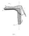
- FIG. 1illustrates a perspective view of an illumination device according to an example embodiment
- FIG. 2Aillustrates a perspective view of an illumination device with various parts removed for clarity according to an example embodiment
- FIG. 2Billustrates a perspective view of an illumination device with various parts removed for clarity according to an example embodiment
- FIG. 3illustrates a side view of a housing of an illumination device with various parts removed for clarity according to an example embodiment
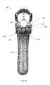
- FIG. 4illustrates a top view of a housing of an illumination device according to an example embodiment
- FIG. 5illustrates a bottom view of a housing of an illumination device with various parts removed for clarity according to an example embodiment
- FIG. 6illustrates one housing part of a housing of an illumination device according to an example embodiment
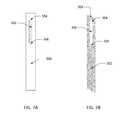
- FIG. 7Aillustrates a pull tab according to an example embodiment
- FIG. 7Billustrates a pull tab according to an example embodiment
- FIG. 8illustrates a securing member according to an example embodiment
- FIG. 9illustrates a side view of a speculum according to an example embodiment
- FIG. 10illustrates a perspective rear view of a speculum according to an example embodiment
- FIG. 11illustrates a bottom view of a speculum according to an example embodiment
- FIG. 12illustrates a perspective view of a bottom blade of a speculum according to an example embodiment
- FIG. 13illustrates a perspective view of an illumination device with various parts removed for clarity according to an example embodiment.
- Various embodiments of the present inventiongenerally provide for a system configured to provide illumination for a speculum and associated methods of illuminating a speculum.
- the systemmay include a speculum and an illumination device configured to illuminate the speculum and/or a patient during a physical examination.
- a speculummay be configured to receive an illumination device in a speculum cavity.
- the speculum cavitymay be configured to receive the illumination device and may be further configured to illuminate the speculum and/or a patient during a physical examination via a light pipe that extends from the speculum cavity to a speculum blade.
- the illumination devicemay be configured to provide for easy illumination with a pull tab that is configured to switch the illumination device between an illuminated state and an unilluminated state.
- the systemmay advantageously provide for easy replacement of an illumination device by providing an illumination device with a pull tab configured to allow for the removal of the illumination device from a speculum cavity.
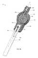
- FIG. 1illustrates an illumination device 10 for a system configured to illuminate a speculum and/or a patient during a physical exam according to one embodiment of the present invention.
- the illumination device 10may comprise a housing 100 configured to be received within a speculum cavity 508 , as shown in FIG. 11 .
- the illumination device 10may comprise a housing 100 that includes a first housing part 110 and a second housing part 120 , as shown in FIG. 1 .
- the illumination device 10may include a securing member 150 configured to couple the first housing part 110 and second housing part 120 to one another.
- the illumination device 10may also include a pull tab 300 that is partially disposed within the housing 100 .
- embodiments hereinmay provide an illumination device for a system configured to illuminate a speculum and/or a patient that may be modular in design. Accordingly, replacement or repair of the illumination device is facilitated by providing a housing that provides accessible means to various illumination device components. Further, some embodiments may provide a housing for an illumination device that may be discarded after use, such as in an instance where the illumination device has become contaminated with a biological agent and/or is designed to be a single-use component.
- the housing 100may comprise a single housing part that is formed from an elastomeric material.
- a single housingmay be shaped to form a clam shell design such that a hinged portion of the housing may provide access to a housing cavity defined therein.
- the hinged portionmay be defined by a first portion of the housing such that one part of a second and third portion of the housing may be moved away from and/or toward a second part of the second and third portion of the housing.
- the second portionmay define the hinged portion along a longitudinal axis, such that one part of a first, second and third portion of the housing may be moved away from and/or toward a second part of the first, second and third portion of the housing.
- embodiments of the present inventionmay advantageously provide for facilitating the assembly of the illumination system.
- the illumination devicemay be configured to be secured within a speculum cavity via an interference fit without the need for a securing member in some embodiments.
- the housing 100may define a first portion 102 , a second portion 104 , and a third portion 106 , as shown in FIG. 1 .
- the first portion 102 , second portion 104 , and third portion 106may be different regions of the housing 100 .
- the first portion 102may be a top region of the housing 100 near an illumination source 200
- the second portion 104may be a middle region of the housing
- the third portion 106may be a bottom portion of the housing.
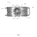
- the housing 100may further define a plurality of raised grooves 130 , 132 , 134 , 136 .
- the plurality of raised groovesmay be configured to mate with reciprocal channels 520 , 522 , 524 , 526 of a speculum cavity 508 , as shown in FIG. 11 .
- FIG. 4 and FIG. 11illustrate a housing defining four grooves and a speculum cavity defining four reciprocal channels, one of ordinary skill in the art in view of this disclosure may appreciate that the housing and speculum cavity may define any number of grooves and reciprocal channels.
- the plurality of raised groovesmay extend longitudinally from the third portion 106 of the housing to at least the second portion 104 of the housing, as shown in FIG. 1 .
- the plurality of raised groovesmay extend from the third portion 106 of the housing to the first portion 102 of the housing.
- embodiments of the present inventionmay advantageously provide for an illumination device that is securely disposed within a speculum cavity.
- the plurality of raised grooves of the illumination device housing and the reciprocal channels of the speculum cavitymay be configured to minimize lateral movement of the illumination device within the speculum cavity when the illumination device is inserted therein.
- the plurality of raised grooves and the reciprocal channelsmay be configured to advantageously provide for the alignment of an illumination source of the illumination device and a light pipe of the speculum so as to maximize the amount of illumination along a direction angled away from the longitudinal axis of the illumination device, as described in greater detail below.
- the housing 100may comprise at least a first and second housing part 110 , 120 .
- the housing 100may also define a plurality of channels 114 , 124 configured to receive a securing member 150 therein so as to bias the first housing part 110 in engagement with the second housing part 120 .
- FIG. 1illustrates a single securing member 150 configured to bias the first and second housing parts 110 , 120 in engagement with one another, one of skill in the art may appreciate that the housing may include any number of securing members and a corresponding number of channels configured to receive the securing members therein. As shown in FIG.
- the plurality of channels 114 , 124may be defined by the second portion 104 (e.g., the middle portion and/or region) of the housing 100 .
- the housingmay define a plurality of channels in the second portion for a securing member and another plurality of channels in the first portion for a second securing member.
- the first and third portions of the housingmay define a plurality of channels configured to receive a securing member respectively therein.
- a plurality of channelsmay be defined by any of the portions of the housing, and the housing may define any number of plurality of channels configured to receive a securing member therein so as to bias the first and second housing parts in engagement with one another.
- the securing member 150may be a wire clip configured to bias the first housing part and second housing part to maintain engagement with one another.
- the wire clipmay comprise a spring clip configured to exert a force inwardly between two arms.
- a first arm 152 and a second arm 154may each be configured to exert a force inwardly (e.g., towards each other).
- the securing member 150may be removed from an illumination device by exerting an outward force so as to pull the two arms 152 , 154 away from one another.
- the securing membermay include an elastomeric material such as, for example, an elastomeric o-ring.
- a first securing membermay be a wire clip, while a second securing member may include an elastomeric material.
- the first housing part 110 and the second housing part 120may define a cavity 140 therebetween. As shown in FIGS. 2A, 2B and 6 , the second housing part 120 may define at least a portion of the cavity 140 . Accordingly, the first housing part 110 and the second housing part 120 may define and enclose the cavity 140 therebetween when the first and second housing parts are in engagement with one another.
- the housing 100may define a pull tab stop 145 . As shown in FIG. 6 , for example, the inner surface 121 of the second housing part 120 may define a portion of the pull tab stop 145 , which may be an extension of the inner surface or some other protruding feature attached to, coupled with, or integral to the inner surface.
- the inner surface 111 of the first housing part 110may define a corresponding portion of the pull tab stop 145 , as shown in FIG. 5 .
- the second housing part 120may define approximately half of the pull tab stop 145 (e.g., with a semi-circular shaped portion), while the first housing part 110 may define approximately the other half of the pull tab stop 145 (e.g., with a reciprocally shaped, semi-circular portion).
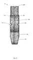
- FIGS. 2A and 2Bshow components of the illumination device 10 with a first housing part 110 and at least one battery removed for ease of explanation.
- FIGS. 2A and 2Billustrate at least one battery 250 disposed within the housing cavity 140 proximate the second portion 104 .
- the second portion of the housingmay define a shape that substantially corresponds to the shape of the at least one battery, as shown in FIG. 1 .
- the first portion 102may define a shape that substantially corresponds to the shape of the illumination source.
- the third portion 106may include a tapered portion 107 so as to advantageously provide for easier removal from a speculum cavity 508 .
- the tapered portion 107may be configured to provide a spacing and/or a gap between the housing 100 of the illumination device and the interior surface of the speculum cavity.
- a usermay be able to grasp the tapered portion 107 of the housing 100 from within the spacing and/or gap defined between the tapered portion and the inner surface of the speculum cavity 508 so as to remove the illumination device 10 from the speculum cavity.
- the illumination device 10may include an illumination source 200 disposed within the cavity 140 proximate the first portion 102 , as shown in FIG. 2 .
- the illumination source 200may include a light emitting diode.
- the illumination source 200may include a first electrical contact 202 and a second electrical contact 204 that extend from the illumination source.
- the first electrical contact 202 and the second electrical contact 204may extend longitudinally within the housing cavity 140 in a direction from the first portion 102 towards the second portion 104 of the housing.
- electrical contacts 202 , 204may be configured to be disposed such that an electrical connection is maintained between each of the respective electrical contacts 202 , 204 and at least one battery 250 .
- one electrical contact 204is disposed between the at least one battery 250 and the second housing part 120
- another electrical contact 202is configured to be disposed between the first housing part (not shown) and at least one other battery (not shown).
- the pull tab 300may be disposed within the cavity 140 . As shown in FIGS. 2A, 2B, 7A and 7B , the pull tab 300 may define a pull tab slot 302 therethrough. The pull tab slot 302 may further define a proximal end 304 and a distal end 306 . According to one embodiment, the pull tab 300 may be configured to move between a first position and a second position. For example, in FIG. 2A , the pull tab 300 is shown disposed proximate the first position, whereas in FIG. 2B , the pull tab shown is disposed proximate the second position.
- a distal end 306 of the pull tab slot 302may be disposed proximate the pull tab stop 145 , as shown in FIG. 2A .
- the pull tab 300may be positioned to interrupt an electrical circuit, such that the illumination device 10 is in an unilluminated state.
- the pull tab 300may be positioned between two batteries (e.g., the battery 250 and another battery, not shown) such that the two batteries are prohibited from contacting one another, thereby interrupting the electrical circuit that would otherwise be formed between the two batteries and the illumination source 200 via the electrical contacts 202 , 204 .
- the pull tab 300may be positioned in the first position such that the pull tab is disposed between at least one battery 250 and a portion of the electrical circuit, such as an electrical contact of the illumination source, thereby interrupting the electrical circuit such that the illumination device is in an unilluminated state.
- the pull tab 300in the second position, may be disposed such that a proximal end 304 of the pull tab slot 302 is disposed proximate the pull tab stop 145 . Accordingly, when the pull tab is moved from the first position to the second position, the pull tab stop 145 may be configured to retain the pull tab 300 within the housing of the illumination device, as the pull tab stop 145 is configured to contact the proximal end 304 of the pull tab slot 302 in the second position and prohibit the pull tab from further movement in that direction. In addition, some embodiments may include a pull tab 300 configured to advantageously provide for ease of removal from a speculum cavity 508 .
- the pull tabmay be prohibited from further movement along the longitudinal axis, such as the illumination axis I.
- the pull tab stop 145may be configured to retain the pull tab.
- the pull tab stop 145may extend along a direction orthogonal to the longitudinal axis of the pull tab and/or the longitudinal axis along which the pull tab travels between the two positions, such as illumination axis I.
- the pull tab stopmay be configured to transmit the tension such that the illumination device is moved along a direction parallel to the longitudinal axis of the pull tab, thereby assisting in the removal of the illumination device from the speculum cavity 508 .
- the pull tabmay be pulled from the first position to the second position.
- a usermay continue to pull on the pull tab, which may cause the pull tab stop and the pull tab to contact one another.
- the tension applied to the pull tabmay cause the user to remove the illumination device from the speculum cavity.
- the pull tab 300may include a proximal end slit 308 disposed proximate the proximal end 304 of the pull tab slot 302 .
- embodiments provided hereinmay be configured to provide a pull tab for an illumination device configured to move between a first position and a second position.
- the pull tab 300may be positioned to interrupt an electrical circuit in a first position such that the illumination device 10 is in an unilluminated state.
- the pull tab 300may be positioned so as to complete an electrical circuit such that the illumination device is in an illuminated state, as described in greater detail herein.
- the pull tab 300may be configured to be removed from the illumination device 10 while the illumination device is disposed within the speculum cavity 508 .
- the pull tab 300may define a proximal end slit 308 disposed proximate the proximal end 304 .
- the proximal end slit 308may extend from the pull tab slot 302 to a peripheral edge of the pull tab 300 .
- the proximal end slit 308may define a width that is narrower than a diameter of the pull tab stop 145 .
- the proximal end slit 308may be configured to allow the pull tab stop 145 to pass from the proximal end 304 of the pull tab slot 302 , through the proximal end slit 308 , and past a peripheral edge of the pull tab 300 .
- the pull tab 300may be configured to be removed from the illumination device 10 while the illumination device remains within the speculum cavity 508 .
- the electrical circuitwhen the pull tab 300 is disposed in the second position, the electrical circuit is completed (e.g., the pull tab is out of the way) such that the illumination device is in an illuminated state. Accordingly, when the pull tab 300 is disposed in the second position, the electrical circuit energizes the illumination source 200 so as to provide illumination. For example, when the pull tab is moved from the first position to the second position, the pull tab may be removed from a position between two batteries, thereby allowing the two batteries to contact one another. When the two batteries contact one another, an electrical circuit is completed so as to provide the illumination source with electrical power and thereby provide illumination.
- the at least one batterymay be configured to provide electrical power to the illumination source for illumination for at least 10 minutes.
- the pull tab 300may be configured to move between the first and second position. As such, when the pull tab 300 is disposed in the second position (i.e., the electrical circuit energizes the illumination source), the pull tab may be moved from a second position to a first position, thereby interrupting the electrical circuit, such that the illumination device 10 changes from an illuminated state to an unilluminated state.
- the illumination device 10may further include a current regulator 400 , such as a circuit board including at least one resistor.
- a current regulator 400such as a circuit board including at least one resistor.
- the first and second electrical contacts 202 , 204may be disposed such that an electrical connection is maintained between the current regulator 400 and the electrical contacts 202 , 204 regardless of the position of the pull tab 300 .
- the electrical contacts 202 , 204may be disposed such that at least one electrical contact 202 , 204 maintains an electrical connection with the current regulator 400 .
- a first electrical contact 202may be disposed to maintain an electrical connection between the current regulator 400 and the electrical contact 202 .
- the current regulator 400may include at least one current regulator contact 402 . As shown in FIG. 13 , the current regulator contact 402 may be disposed to maintain an electrical connection between the current regulator 400 and the at least one battery 250 . Accordingly, the current regulator 400 may define at least a portion of the electrical circuit between the at least one battery 250 and the illumination source 200 . Embodiments herein that include such a current regulator may advantageously provide for more consistent illumination over a period of time. For example, an illumination device with a current regulator may be configured to prevent the brightness level of the illumination source from dropping off a few minutes after electrical power is provided to the illumination source. As a result, illumination from the illumination source is more consistent when an electrical circuit is completed to provide electrical power to the illumination source. Further, for embodiments having a single battery, a voltage booster (not shown) may optionally be included in the electrical circuit to advantageously provide for sufficient illumination.
- FIGS. 9-12show a speculum 500 that is configured to receive an illumination device 10 therein for illuminating a speculum and/or a patient during a physical exam.
- the speculum 500may comprise a first blade 502 and a second blade 504 .
- the speculum 500may include a handle 506 configured to be gripped by a user during a physical examination.
- the handle 506 and the second blade 504may be integrally formed as a unitary member.
- the speculum 500may include a light pipe 510 .
- Further example speculums configured to receive an illumination device thereinare discussed in commonly-assigned U.S. Pat. No. 8,157,728, dated Apr. 17, 2012, titled “VAGINAL SPECULUM,” which is hereby incorporated by reference in its entirety.
- the light pipe 510may be integrally formed with the second blade 504 and/or the handle 506 of the speculum. As shown in FIG. 10 , the light pipe 510 may define a proximal end 512 and a distal end 514 . In some embodiments, the proximal end 512 of the light pipe 510 may be disposed proximate the handle 506 , and the distal end 514 of the light pipe 510 may be disposed proximate a point on the interior surface of the second blade 504 .
- embodiments hereinmay advantageously provide for the illumination of a speculum and/or a patient by manipulating illumination provided by an illumination device disposed in one portion of the speculum to another portion of the speculum.
- the light pipemay be configured to manipulate the illumination provided by the illumination device in the speculum cavity 508 such that the light is transmitted to and/or illuminates the distal end 514 of the light pipe 510 .
- the light pipe 510may be configured to direct illumination within a speculum and/or toward a patient during a physical exam along a direction that is disposed at an angle to an illumination axis I defined by the illumination source and illumination device (shown in FIGS. 1 and 9 ).
- the housing of the illumination device and the illumination sourcemay define an illumination axis I that is parallel to the longitudinal axis of the speculum cavity when inserted therein.
- the light pipemay be configured to direct the illumination along an axis T that is tangential to the light pipe proximate the distal end 514 of the light pipe.
- the speculum 500may be constructed from a transparent material.
- the light pipe 510 , the first blade 502 and/or the second blade 504may be constructed from a transparent material, such as a plastic.
- the speculum 500may be constructed from a transparent material that is also refractive. As such, when illumination is provided to the light pipe via the illumination device, the light pipe, first blade, and/or second blade may be configured to amplify and/or concentrate the illumination towards a desired direction.
- Embodiments hereinmay advantageously provide for increased illumination for a speculum for use during a physical exam of a patient. Further, some embodiments may advantageously provide for illumination of a speculum and/or patient that is substantially consistent in brightness.
- an illumination devicemay be configured to be easily inserted within a speculum.
- the illumination devicemay be configured to advantageously provide for easy removal from a speculum cavity by providing a tapered portion to grasp for removal when the illumination device is disposed within the speculum cavity.
- the illumination devicemay include a pull tab that may be used to activate the illumination device and/or provide for easy removal of the illumination device from a speculum cavity by providing a portion to pull upon when the illumination device is in place within the speculum cavity.
Landscapes
- Health & Medical Sciences (AREA)
- Life Sciences & Earth Sciences (AREA)
- Surgery (AREA)
- General Health & Medical Sciences (AREA)
- Public Health (AREA)
- Veterinary Medicine (AREA)
- Nuclear Medicine, Radiotherapy & Molecular Imaging (AREA)
- Animal Behavior & Ethology (AREA)
- Molecular Biology (AREA)
- Engineering & Computer Science (AREA)
- Biomedical Technology (AREA)
- Heart & Thoracic Surgery (AREA)
- Medical Informatics (AREA)
- Biophysics (AREA)
- Radiology & Medical Imaging (AREA)
- Physics & Mathematics (AREA)
- Pathology (AREA)
- Optics & Photonics (AREA)
- Gynecology & Obstetrics (AREA)
- Reproductive Health (AREA)
- Endoscopes (AREA)
Abstract
Description
Claims (21)
Priority Applications (1)
| Application Number | Priority Date | Filing Date | Title |
|---|---|---|---|
| US13/839,205US9314149B2 (en) | 2013-03-15 | 2013-03-15 | Illumination device, system, and method of use |
Applications Claiming Priority (1)
| Application Number | Priority Date | Filing Date | Title |
|---|---|---|---|
| US13/839,205US9314149B2 (en) | 2013-03-15 | 2013-03-15 | Illumination device, system, and method of use |
Publications (2)
| Publication Number | Publication Date |
|---|---|
| US20140275790A1 US20140275790A1 (en) | 2014-09-18 |
| US9314149B2true US9314149B2 (en) | 2016-04-19 |
Family
ID=51530291
Family Applications (1)
| Application Number | Title | Priority Date | Filing Date |
|---|---|---|---|
| US13/839,205Expired - Fee RelatedUS9314149B2 (en) | 2013-03-15 | 2013-03-15 | Illumination device, system, and method of use |
Country Status (1)
| Country | Link |
|---|---|
| US (1) | US9314149B2 (en) |
Cited By (6)
| Publication number | Priority date | Publication date | Assignee | Title |
|---|---|---|---|---|
| US8910831B2 (en) | 2009-07-10 | 2014-12-16 | Aervoe Industries, Inc. | System for dispensing sprayable material |
| USD781477S1 (en)* | 2015-04-06 | 2017-03-14 | Clearspec, Llc | Illuminator for a medical speculum |
| US10441379B2 (en) | 2017-12-28 | 2019-10-15 | 3Gen, Inc. | Multipurpose medical illuminator with magnification |
| US10687699B2 (en) | 2017-03-17 | 2020-06-23 | CEEK Enterprises | Lighting module for a medical device and methods for using the same |
| US11395714B2 (en) | 2019-11-11 | 2022-07-26 | Dermlite Llc | Medical illuminator with variable polarization |
| USD963908S1 (en) | 2017-03-24 | 2022-09-13 | Ceek Women's Health, Inc. | Medical device lighting module |
Families Citing this family (26)
| Publication number | Priority date | Publication date | Assignee | Title |
|---|---|---|---|---|
| US8821395B2 (en) | 2005-04-01 | 2014-09-02 | Welch Allyn, Inc. | Vaginal speculum apparatus |
| US9307897B2 (en) | 2010-09-28 | 2016-04-12 | Obp Corporation | Disposable speculum having lateral stabilizing mechanism |
| US9913577B2 (en) | 2010-09-28 | 2018-03-13 | Obp Medical Corporation | Speculum |
| DE102012018170B4 (en)* | 2012-09-14 | 2014-10-09 | Corlife Ohg | Illumination device for surgical purposes, surgical instrument therewith, part of such an instrument and set of lighting device, surgical instrument and / or instrument part |
| US10420538B2 (en) | 2015-02-05 | 2019-09-24 | Obp Medical Corporation | Illuminated surgical retractor |
| US9867602B2 (en) | 2015-02-05 | 2018-01-16 | Obp Medical Corporation | Illuminated surgical retractor |
| ES2968069T3 (en) | 2015-06-03 | 2024-05-07 | Obp Surgical Corp | Retractor |
| US10939899B2 (en) | 2015-06-03 | 2021-03-09 | Obp Medical Corporation | End cap assembly for retractor and other medical devices |
| US10881387B2 (en) | 2015-06-03 | 2021-01-05 | Obp Medical Corporation | Retractor |
| CN105816144A (en)* | 2016-05-24 | 2016-08-03 | 江西华清博恩生物科技有限公司 | Compact medical lighting light source of disposable sterile vaginal dilator |
| CN105796045A (en)* | 2016-05-24 | 2016-07-27 | 江西华清博恩生物科技有限公司 | Disposable aseptic vagina illuminating system |
| US10722621B2 (en) | 2016-07-11 | 2020-07-28 | Obp Medical Corporation | Illuminated suction device |
| US10448808B2 (en) | 2017-02-20 | 2019-10-22 | Yih-Chiou Tsai | Disposable medical device with a lighting effect |
| PT3260039T (en)* | 2017-02-21 | 2020-01-20 | Yih Chiou Tsai | Disposable medical device with a lighting effect |
| US10401001B2 (en) | 2017-05-10 | 2019-09-03 | Sunoptic Technologies Llc | Disposable light source for an endoscope or retractor |
| US10687793B2 (en) | 2017-07-18 | 2020-06-23 | Obp Medical Corporation | Minimally invasive no touch (MINT) procedure for harvesting the great saphenous vein (GSV) and venous hydrodissector and retractor for use during the MINT procedure |
| US10278572B1 (en) | 2017-10-19 | 2019-05-07 | Obp Medical Corporation | Speculum |
| US10799229B2 (en) | 2018-02-20 | 2020-10-13 | Obp Medical Corporation | Illuminated medical devices |
| EP4606345A2 (en) | 2018-02-20 | 2025-08-27 | CooperSurgical, Inc. | Illuminated medical devices |
| USD911521S1 (en) | 2019-02-19 | 2021-02-23 | Obp Medical Corporation | Handle for medical devices including surgical retractors |
| USD904607S1 (en) | 2019-05-07 | 2020-12-08 | Obp Medical Corporation | Nasal retractor |
| TWD201116S (en)* | 2019-05-17 | 2019-11-21 | 蔡益秋 | vaginal dilator part |
| US10959609B1 (en) | 2020-01-31 | 2021-03-30 | Obp Medical Corporation | Illuminated suction device |
| US10966702B1 (en) | 2020-02-25 | 2021-04-06 | Obp Medical Corporation | Illuminated dual-blade retractor |
| US20240245287A1 (en)* | 2023-01-25 | 2024-07-25 | Medline Industries, Lp | Lighted disposable speculum |
| US12318080B2 (en) | 2023-07-21 | 2025-06-03 | Coopersurgical, Inc. | Illuminated surgical retractor capable of hand-held operation and of being mounted to a fixed frame |
Citations (55)
| Publication number | Priority date | Publication date | Assignee | Title |
|---|---|---|---|---|
| US3789835A (en) | 1972-03-16 | 1974-02-05 | R Whitman | Illuminating attachments for vaginal speculum |
| US4067323A (en) | 1975-12-02 | 1978-01-10 | Concept Inc. | Light for vaginal speculum |
| USD343453S (en) | 1993-05-05 | 1994-01-18 | Laparomed Corporation | Handle for laparoscopic surgical instrument |
| USD367087S (en) | 1995-01-27 | 1996-02-13 | Srl, Inc. | Toy flashlight |
| USD375372S (en) | 1995-03-21 | 1996-11-05 | Allen David M | Pocket flashlight |
| US6004265A (en) | 1999-03-01 | 1999-12-21 | Hsu; Jin-Cherng | Vaginal speculum with light guide means |
| USD425226S (en) | 1999-08-11 | 2000-05-16 | Emissive Energy Corporation | Miniature flashlight |
| USD445928S1 (en) | 2000-12-11 | 2001-07-31 | Streamlight, Inc. | Keylight |
| USD446325S1 (en) | 2000-08-17 | 2001-08-07 | Acolyte Systems Inc. | Safety light |
| USD446324S1 (en) | 1999-04-05 | 2001-08-07 | Eveready Battery Company, Inc. | Squeeze light |
| US6379296B1 (en) | 1999-03-26 | 2002-04-30 | Richard W. Baggett | Medical lighting device |
| USD457670S1 (en) | 2001-08-31 | 2002-05-21 | David Allen | X-light personal flashlight |
| USD482469S1 (en) | 2000-08-17 | 2003-11-18 | Acolyte Systems Inc. | Disposable light |
| USD492050S1 (en) | 2002-02-25 | 2004-06-22 | Sheng Lone Chung | Light for a key |
| USD498553S1 (en) | 2004-04-06 | 2004-11-16 | Wen-Sung Lee | Light device |
| USD498864S1 (en) | 2004-04-06 | 2004-11-23 | Wen-Sung Lee | Light device |
| USD501266S1 (en) | 2004-01-13 | 2005-01-25 | Brookstone Purchasing, Inc. | Flashlight |
| USD507369S1 (en) | 2004-11-10 | 2005-07-12 | Michael Waters | Light module |
| USD507368S1 (en) | 2004-11-10 | 2005-07-12 | Michael Waters | Dual light module |
| USD507671S1 (en) | 2004-11-02 | 2005-07-19 | Kevin M. Rice | Light for attachment to a cellular phone |
| USD513084S1 (en) | 2003-12-18 | 2005-12-20 | Pellcan Products, Inc. | Clip light |
| US20060007669A1 (en) | 2004-07-09 | 2006-01-12 | Blackburn Paul C | Ergonomic hand-mounted illumination device |
| US20060029901A1 (en) | 2004-07-02 | 2006-02-09 | Discus Dental Impressions, Inc. | Light guide for dentistry applications |
| US7029439B2 (en)* | 2002-07-09 | 2006-04-18 | Welch Allyn, Inc. | Medical diagnostic instrument |
| US20080045801A1 (en)* | 2006-08-15 | 2008-02-21 | M.S. Vision Ltd. | Intubation laryngoscope with detachable blades |
| USD565216S1 (en) | 2007-11-29 | 2008-03-25 | Craig S. Markell | LED keychain light |
| USD576323S1 (en) | 2007-12-03 | 2008-09-02 | Juan Enrique Cienfuegos | Multifunction light source |
| USD577143S1 (en) | 2008-04-19 | 2008-09-16 | Benson Ping-Shen Lu | Cabinet light |
| US20080228038A1 (en) | 2005-04-01 | 2008-09-18 | Welch Allyn, Inc. | Illumination Assembly For Use With Vaginal Speculum Apparatus |
| USD581566S1 (en) | 2006-05-09 | 2008-11-25 | Welch Allyn, Inc. | Illumination assembly |
| US20090076334A1 (en) | 2007-09-19 | 2009-03-19 | Tien-Sheng Chen | Illuminated Vaginal Speculum and Illumination Device |
| USD593693S1 (en) | 2008-02-12 | 2009-06-02 | Crestwood Partners Llc | Combined flashlight and docking station |
| USD594148S1 (en) | 2008-04-04 | 2009-06-09 | Hesco Bastion Limited | Miniature torch |
| USD598593S1 (en) | 2008-07-09 | 2009-08-18 | Eveready Battery Co., Inc. | Lighting device |
| US20090312610A1 (en)* | 2008-06-13 | 2009-12-17 | Obp Corporation | Disposable Speculums Having Single-Sided Support and Operating Mechanism |
| USD627092S1 (en) | 2010-02-01 | 2010-11-09 | Points Of Light, Inc. | Flashlight |
| US7841751B2 (en) | 2006-04-28 | 2010-11-30 | Mulani Nizar A | Pediatric adapter for transillumination |
| US7909759B2 (en)* | 2004-11-23 | 2011-03-22 | Truphatek International Ltd | Handheld penknife-like laryngoscope |
| USD642310S1 (en) | 2010-10-05 | 2011-07-26 | Mechanix Wear, Inc. | Glove light |
| USD656644S1 (en) | 2011-08-18 | 2012-03-27 | Wen-Sung Lee | Cap light |
| US8142352B2 (en) | 2006-04-03 | 2012-03-27 | Welch Allyn, Inc. | Vaginal speculum assembly having portable illuminator |
| US8152330B2 (en) | 2001-11-07 | 2012-04-10 | Michael Waters | Lighted reading glasses |
| US20120108907A1 (en) | 2009-07-07 | 2012-05-03 | Benedito Fitipaldi | Vaginal Speculum Provided With An Automatically Actuated Illumination System |
| USD659845S1 (en) | 2010-06-03 | 2012-05-15 | 2035, Inc. | Laser medical instrument |
| USD676992S1 (en) | 2012-01-31 | 2013-02-26 | Koehler-Bright Star LLC | Cap lamp |
| US8409082B2 (en) | 2008-07-07 | 2013-04-02 | Karl Storz Gmbh & Co. Kg | Video endoscope with switchable semiconductor light sources |
| USD683489S1 (en) | 2011-07-27 | 2013-05-28 | Wen-Sung Lee | Headlamp |
| USD690043S1 (en) | 2010-10-04 | 2013-09-17 | Guohua Sun | LED flashlight |
| USRE44806E1 (en)* | 2003-03-20 | 2014-03-18 | Welch Allyn, Inc. | Electrical adapter for medical diagnostic instruments using LEDs as illumination sources |
| US8740780B2 (en) | 2011-04-07 | 2014-06-03 | Olympus Medical Systems Corp. | Endoscope and illumination apparatus for endoscope |
| USD710500S1 (en) | 2012-04-05 | 2014-08-05 | Bridea Hong Kong Ltd. | Medical instrument |
| US8808175B2 (en) | 2012-04-12 | 2014-08-19 | Coloplast A/S | Vaginal manipulator including light source |
| USD712561S1 (en) | 2013-01-09 | 2014-09-02 | Koninklijke Philips N.V. | Light therapy device |
| US20140293590A1 (en) | 2013-04-01 | 2014-10-02 | Vinod V. Pathy | Lighting device |
| US9173648B2 (en) | 2011-09-23 | 2015-11-03 | Invuity, Inc. | Illuminated and modular soft tissue retractor |
- 2013
- 2013-03-15USUS13/839,205patent/US9314149B2/ennot_activeExpired - Fee Related
Patent Citations (56)
| Publication number | Priority date | Publication date | Assignee | Title |
|---|---|---|---|---|
| US3789835A (en) | 1972-03-16 | 1974-02-05 | R Whitman | Illuminating attachments for vaginal speculum |
| US4067323A (en) | 1975-12-02 | 1978-01-10 | Concept Inc. | Light for vaginal speculum |
| USD343453S (en) | 1993-05-05 | 1994-01-18 | Laparomed Corporation | Handle for laparoscopic surgical instrument |
| USD367087S (en) | 1995-01-27 | 1996-02-13 | Srl, Inc. | Toy flashlight |
| USD375372S (en) | 1995-03-21 | 1996-11-05 | Allen David M | Pocket flashlight |
| US6004265A (en) | 1999-03-01 | 1999-12-21 | Hsu; Jin-Cherng | Vaginal speculum with light guide means |
| US6379296B1 (en) | 1999-03-26 | 2002-04-30 | Richard W. Baggett | Medical lighting device |
| USD446324S1 (en) | 1999-04-05 | 2001-08-07 | Eveready Battery Company, Inc. | Squeeze light |
| USD425226S (en) | 1999-08-11 | 2000-05-16 | Emissive Energy Corporation | Miniature flashlight |
| USD482469S1 (en) | 2000-08-17 | 2003-11-18 | Acolyte Systems Inc. | Disposable light |
| USD446325S1 (en) | 2000-08-17 | 2001-08-07 | Acolyte Systems Inc. | Safety light |
| USD445928S1 (en) | 2000-12-11 | 2001-07-31 | Streamlight, Inc. | Keylight |
| USD457670S1 (en) | 2001-08-31 | 2002-05-21 | David Allen | X-light personal flashlight |
| US8152330B2 (en) | 2001-11-07 | 2012-04-10 | Michael Waters | Lighted reading glasses |
| USD492050S1 (en) | 2002-02-25 | 2004-06-22 | Sheng Lone Chung | Light for a key |
| US7029439B2 (en)* | 2002-07-09 | 2006-04-18 | Welch Allyn, Inc. | Medical diagnostic instrument |
| USRE44806E1 (en)* | 2003-03-20 | 2014-03-18 | Welch Allyn, Inc. | Electrical adapter for medical diagnostic instruments using LEDs as illumination sources |
| USD513084S1 (en) | 2003-12-18 | 2005-12-20 | Pellcan Products, Inc. | Clip light |
| USD501266S1 (en) | 2004-01-13 | 2005-01-25 | Brookstone Purchasing, Inc. | Flashlight |
| USD498553S1 (en) | 2004-04-06 | 2004-11-16 | Wen-Sung Lee | Light device |
| USD498864S1 (en) | 2004-04-06 | 2004-11-23 | Wen-Sung Lee | Light device |
| US20060029901A1 (en) | 2004-07-02 | 2006-02-09 | Discus Dental Impressions, Inc. | Light guide for dentistry applications |
| US20060007669A1 (en) | 2004-07-09 | 2006-01-12 | Blackburn Paul C | Ergonomic hand-mounted illumination device |
| USD507671S1 (en) | 2004-11-02 | 2005-07-19 | Kevin M. Rice | Light for attachment to a cellular phone |
| USD507368S1 (en) | 2004-11-10 | 2005-07-12 | Michael Waters | Dual light module |
| USD507369S1 (en) | 2004-11-10 | 2005-07-12 | Michael Waters | Light module |
| US7909759B2 (en)* | 2004-11-23 | 2011-03-22 | Truphatek International Ltd | Handheld penknife-like laryngoscope |
| US8157728B2 (en) | 2005-04-01 | 2012-04-17 | Welch Allyn, Inc. | Vaginal speculum |
| US20080228038A1 (en) | 2005-04-01 | 2008-09-18 | Welch Allyn, Inc. | Illumination Assembly For Use With Vaginal Speculum Apparatus |
| US8142352B2 (en) | 2006-04-03 | 2012-03-27 | Welch Allyn, Inc. | Vaginal speculum assembly having portable illuminator |
| US7841751B2 (en) | 2006-04-28 | 2010-11-30 | Mulani Nizar A | Pediatric adapter for transillumination |
| USD581566S1 (en) | 2006-05-09 | 2008-11-25 | Welch Allyn, Inc. | Illumination assembly |
| US20080045801A1 (en)* | 2006-08-15 | 2008-02-21 | M.S. Vision Ltd. | Intubation laryngoscope with detachable blades |
| US20090076334A1 (en) | 2007-09-19 | 2009-03-19 | Tien-Sheng Chen | Illuminated Vaginal Speculum and Illumination Device |
| USD565216S1 (en) | 2007-11-29 | 2008-03-25 | Craig S. Markell | LED keychain light |
| USD576323S1 (en) | 2007-12-03 | 2008-09-02 | Juan Enrique Cienfuegos | Multifunction light source |
| USD593693S1 (en) | 2008-02-12 | 2009-06-02 | Crestwood Partners Llc | Combined flashlight and docking station |
| USD594148S1 (en) | 2008-04-04 | 2009-06-09 | Hesco Bastion Limited | Miniature torch |
| USD577143S1 (en) | 2008-04-19 | 2008-09-16 | Benson Ping-Shen Lu | Cabinet light |
| US20090312610A1 (en)* | 2008-06-13 | 2009-12-17 | Obp Corporation | Disposable Speculums Having Single-Sided Support and Operating Mechanism |
| US8409082B2 (en) | 2008-07-07 | 2013-04-02 | Karl Storz Gmbh & Co. Kg | Video endoscope with switchable semiconductor light sources |
| USD598593S1 (en) | 2008-07-09 | 2009-08-18 | Eveready Battery Co., Inc. | Lighting device |
| US20120108907A1 (en) | 2009-07-07 | 2012-05-03 | Benedito Fitipaldi | Vaginal Speculum Provided With An Automatically Actuated Illumination System |
| USD627092S1 (en) | 2010-02-01 | 2010-11-09 | Points Of Light, Inc. | Flashlight |
| USD659845S1 (en) | 2010-06-03 | 2012-05-15 | 2035, Inc. | Laser medical instrument |
| USD690043S1 (en) | 2010-10-04 | 2013-09-17 | Guohua Sun | LED flashlight |
| USD642310S1 (en) | 2010-10-05 | 2011-07-26 | Mechanix Wear, Inc. | Glove light |
| US8740780B2 (en) | 2011-04-07 | 2014-06-03 | Olympus Medical Systems Corp. | Endoscope and illumination apparatus for endoscope |
| USD683489S1 (en) | 2011-07-27 | 2013-05-28 | Wen-Sung Lee | Headlamp |
| USD656644S1 (en) | 2011-08-18 | 2012-03-27 | Wen-Sung Lee | Cap light |
| US9173648B2 (en) | 2011-09-23 | 2015-11-03 | Invuity, Inc. | Illuminated and modular soft tissue retractor |
| USD676992S1 (en) | 2012-01-31 | 2013-02-26 | Koehler-Bright Star LLC | Cap lamp |
| USD710500S1 (en) | 2012-04-05 | 2014-08-05 | Bridea Hong Kong Ltd. | Medical instrument |
| US8808175B2 (en) | 2012-04-12 | 2014-08-19 | Coloplast A/S | Vaginal manipulator including light source |
| USD712561S1 (en) | 2013-01-09 | 2014-09-02 | Koninklijke Philips N.V. | Light therapy device |
| US20140293590A1 (en) | 2013-04-01 | 2014-10-02 | Vinod V. Pathy | Lighting device |
Non-Patent Citations (17)
| Title |
|---|
| Design U.S. Appl. No. 29/434,856, filed Oct. 17, 2012; in re: Vivenzio et al., entitled Illuminator for a Medical Device or the Like. |
| Design U.S. Appl. No. 29/434,858, filed Oct. 17, 2012; in re: Vivenzio et al., entitled Illuminator for a Medical Device or the Like. |
| Disposable Vaginal Speculum With Cordless LED Source, MedGyn Products, Inc. [online] [retrieved May 1, 2014]. Retrieved from the Internet: . (dated 2014) 2 pages. |
| Disposable Vaginal Speculum With Cordless LED Source, MedGyn Products, Inc. [online] [retrieved May 1, 2014]. Retrieved from the Internet: <URL: http://medgyn.com/?wpsc-product=disposable-speculum-cordless-led>. (dated 2014) 2 pages. |
| ER-SPEC Presentation, OBP Medical (dated Apr. 16, 2014), 12 pages. |
| ER-SPEC Single-use Vaginal Specula with Built-In LED-Use Light Source, OBP Medical Inc. . [online] [retrieved May 1, 2014]. Retrieved from the Internet: . (dated 2014) 3 pages. |
| ER-SPEC Single-use Vaginal Specula with Built-In LED-Use Light Source, OBP Medical Inc. . [online] [retrieved May 1, 2014]. Retrieved from the Internet: <URL: https://obpmedical.com/product/er-spec/>. (dated 2014) 3 pages. |
| ER-SPEC� User Manual, OBP Medical (dated Jun. 27, 2013), 10 pages. |
| ER-SPEC, Tired of Search for a Light Source?, OBP Medical Inc. (Rep Brochure) (Feb. 2012 revision) 2 pages. |
| ER-SPEC® User Manual, OBP Medical (dated Jun. 27, 2013), 10 pages. |
| ER-SPECS Single-Use Vaginal Speculum with Built-In Light Source, OBP Medical Inc. (brochure) (dated Apr. 16, 2014) 2 pages. |
| Notice of Allowance from U.S. Appl. No. 29/434,856 dated Jun. 17, 2015. |
| Notice of Allowance from U.S. Appl. No. 29/495,181 dated Nov. 20, 2015. |
| Office Action from U.S. Appl. No. 29/434,858 dated Dec. 4, 2015. |
| Office Action from U.S. Appl. No. 29/434,858 dated Jul. 24, 2015. |
| Restriction Requirement from U.S. Appl. No. 29/495,181 dated Aug. 14, 2015. |
| U.S. Appl. No. 13/839,205, filed Mar. 15, 2013; in re: Vivenzio et al., entitled Illumination Device, System, and Method of Use. |
Cited By (7)
| Publication number | Priority date | Publication date | Assignee | Title |
|---|---|---|---|---|
| US8910831B2 (en) | 2009-07-10 | 2014-12-16 | Aervoe Industries, Inc. | System for dispensing sprayable material |
| USD781477S1 (en)* | 2015-04-06 | 2017-03-14 | Clearspec, Llc | Illuminator for a medical speculum |
| US10687699B2 (en) | 2017-03-17 | 2020-06-23 | CEEK Enterprises | Lighting module for a medical device and methods for using the same |
| US12167838B2 (en) | 2017-03-17 | 2024-12-17 | Ceek Women's Health, Inc. | Lighting module for a medical device and methods for using the same |
| USD963908S1 (en) | 2017-03-24 | 2022-09-13 | Ceek Women's Health, Inc. | Medical device lighting module |
| US10441379B2 (en) | 2017-12-28 | 2019-10-15 | 3Gen, Inc. | Multipurpose medical illuminator with magnification |
| US11395714B2 (en) | 2019-11-11 | 2022-07-26 | Dermlite Llc | Medical illuminator with variable polarization |
Also Published As
| Publication number | Publication date |
|---|---|
| US20140275790A1 (en) | 2014-09-18 |
Similar Documents
| Publication | Publication Date | Title |
|---|---|---|
| US9314149B2 (en) | Illumination device, system, and method of use | |
| US10945594B2 (en) | Vaginal speculum with illuminator | |
| US12167838B2 (en) | Lighting module for a medical device and methods for using the same | |
| US7631981B2 (en) | Disposable medical-examination light | |
| US5060633A (en) | Laryngoscope blade | |
| US20130158350A1 (en) | Electrical connecting element and endoscopy system | |
| USD692998S1 (en) | Anal irrigation device | |
| US5209757A (en) | Illuminated ear cleaning device | |
| US20190142242A1 (en) | Cover removal jig for endoscope, and endoscope system | |
| EP1913864A1 (en) | Illuminator for medical use | |
| ATE507791T1 (en) | TREATMENT INSTRUMENT FOR ENDOSCOPES | |
| JP2008119066A (en) | Endoscopic treatment tool | |
| US9770158B2 (en) | Holding mechanism for endoscope guide member, and endoscope | |
| KR20100044765A (en) | A earpick with lighting | |
| US20220265340A1 (en) | Electrosurgical handheld device, and contact body for an electrosurgical handheld device | |
| GB2491189A (en) | Laryngoscope blade with light and power source | |
| CN110799082B (en) | Endoscope with a detachable handle | |
| CN110799083B (en) | Endoscope with a detachable handle | |
| JPWO2014174989A1 (en) | Endoscopy adapter and endoscope | |
| US11779428B2 (en) | Disposable medical clamp light | |
| JP2004236727A (en) | Observation device for meibomian glands | |
| US20120283517A1 (en) | Instrument handle for a medical diagnostic light, medical diagnostic light and medical diagnostic device | |
| EP2687199A4 (en) | INTEGRATED PUNCH NEEDLE ADAPTER | |
| JP4426214B2 (en) | Endoscope operation unit | |
| CN110809427B (en) | Endoscope with a detachable handle |
Legal Events
| Date | Code | Title | Description |
|---|---|---|---|
| AS | Assignment | Owner name:WELCH ALLYN, INC., NEW YORK Free format text:ASSIGNMENT OF ASSIGNORS INTEREST;ASSIGNORS:VIVENZIO, ROBERT L.;LIA, RAYMOND A.;MCMAHON, MICHAEL T.;AND OTHERS;REEL/FRAME:030767/0247 Effective date:20130417 | |
| AS | Assignment | Owner name:JPMORGAN CHASE BANK, N.A., AS COLLATERAL AGENT, ILLINOIS Free format text:SECURITY INTEREST;ASSIGNORS:ALLEN MEDICAL SYSTEMS, INC.;HILL-ROM SERVICES, INC.;ASPEN SURGICAL PRODUCTS, INC.;AND OTHERS;REEL/FRAME:036582/0123 Effective date:20150908 Owner name:JPMORGAN CHASE BANK, N.A., AS COLLATERAL AGENT, IL Free format text:SECURITY INTEREST;ASSIGNORS:ALLEN MEDICAL SYSTEMS, INC.;HILL-ROM SERVICES, INC.;ASPEN SURGICAL PRODUCTS, INC.;AND OTHERS;REEL/FRAME:036582/0123 Effective date:20150908 | |
| STCF | Information on status: patent grant | Free format text:PATENTED CASE | |
| AS | Assignment | Owner name:JPMORGAN CHASE BANK, N.A., AS COLLATERAL AGENT, ILLINOIS Free format text:SECURITY AGREEMENT;ASSIGNORS:HILL-ROM SERVICES, INC.;ASPEN SURGICAL PRODUCTS, INC.;ALLEN MEDICAL SYSTEMS, INC.;AND OTHERS;REEL/FRAME:040145/0445 Effective date:20160921 Owner name:JPMORGAN CHASE BANK, N.A., AS COLLATERAL AGENT, IL Free format text:SECURITY AGREEMENT;ASSIGNORS:HILL-ROM SERVICES, INC.;ASPEN SURGICAL PRODUCTS, INC.;ALLEN MEDICAL SYSTEMS, INC.;AND OTHERS;REEL/FRAME:040145/0445 Effective date:20160921 | |
| AS | Assignment | Owner name:MORTARA INSTRUMENT SERVICES, INC., WISCONSIN Free format text:RELEASE BY SECURED PARTY;ASSIGNOR:JPMORGAN CHASE BANK, N.A.;REEL/FRAME:050254/0513 Effective date:20190830 Owner name:ALLEN MEDICAL SYSTEMS, INC., ILLINOIS Free format text:RELEASE BY SECURED PARTY;ASSIGNOR:JPMORGAN CHASE BANK, N.A.;REEL/FRAME:050254/0513 Effective date:20190830 Owner name:HILL-ROM SERVICES, INC., ILLINOIS Free format text:RELEASE BY SECURED PARTY;ASSIGNOR:JPMORGAN CHASE BANK, N.A.;REEL/FRAME:050254/0513 Effective date:20190830 Owner name:HILL-ROM COMPANY, INC., ILLINOIS Free format text:RELEASE BY SECURED PARTY;ASSIGNOR:JPMORGAN CHASE BANK, N.A.;REEL/FRAME:050254/0513 Effective date:20190830 Owner name:WELCH ALLYN, INC., NEW YORK Free format text:RELEASE BY SECURED PARTY;ASSIGNOR:JPMORGAN CHASE BANK, N.A.;REEL/FRAME:050254/0513 Effective date:20190830 Owner name:VOALTE, INC., FLORIDA Free format text:RELEASE BY SECURED PARTY;ASSIGNOR:JPMORGAN CHASE BANK, N.A.;REEL/FRAME:050254/0513 Effective date:20190830 Owner name:MORTARA INSTRUMENT, INC., WISCONSIN Free format text:RELEASE BY SECURED PARTY;ASSIGNOR:JPMORGAN CHASE BANK, N.A.;REEL/FRAME:050254/0513 Effective date:20190830 Owner name:ANODYNE MEDICAL DEVICE, INC., FLORIDA Free format text:RELEASE BY SECURED PARTY;ASSIGNOR:JPMORGAN CHASE BANK, N.A.;REEL/FRAME:050254/0513 Effective date:20190830 Owner name:HILL-ROM, INC., ILLINOIS Free format text:RELEASE BY SECURED PARTY;ASSIGNOR:JPMORGAN CHASE BANK, N.A.;REEL/FRAME:050254/0513 Effective date:20190830 | |
| AS | Assignment | Owner name:JPMORGAN CHASE BANK, N.A., ILLINOIS Free format text:SECURITY AGREEMENT;ASSIGNORS:HILL-ROM HOLDINGS, INC.;HILL-ROM, INC.;HILL-ROM SERVICES, INC.;AND OTHERS;REEL/FRAME:050260/0644 Effective date:20190830 | |
| MAFP | Maintenance fee payment | Free format text:PAYMENT OF MAINTENANCE FEE, 4TH YEAR, LARGE ENTITY (ORIGINAL EVENT CODE: M1551); ENTITY STATUS OF PATENT OWNER: LARGE ENTITY Year of fee payment:4 | |
| AS | Assignment | Owner name:HILL-ROM HOLDINGS, INC., ILLINOIS Free format text:RELEASE OF SECURITY INTEREST AT REEL/FRAME 050260/0644;ASSIGNOR:JPMORGAN CHASE BANK, N.A.;REEL/FRAME:058517/0001 Effective date:20211213 Owner name:BARDY DIAGNOSTICS, INC., ILLINOIS Free format text:RELEASE OF SECURITY INTEREST AT REEL/FRAME 050260/0644;ASSIGNOR:JPMORGAN CHASE BANK, N.A.;REEL/FRAME:058517/0001 Effective date:20211213 Owner name:VOALTE, INC., FLORIDA Free format text:RELEASE OF SECURITY INTEREST AT REEL/FRAME 050260/0644;ASSIGNOR:JPMORGAN CHASE BANK, N.A.;REEL/FRAME:058517/0001 Effective date:20211213 Owner name:HILL-ROM, INC., ILLINOIS Free format text:RELEASE OF SECURITY INTEREST AT REEL/FRAME 050260/0644;ASSIGNOR:JPMORGAN CHASE BANK, N.A.;REEL/FRAME:058517/0001 Effective date:20211213 Owner name:WELCH ALLYN, INC., NEW YORK Free format text:RELEASE OF SECURITY INTEREST AT REEL/FRAME 050260/0644;ASSIGNOR:JPMORGAN CHASE BANK, N.A.;REEL/FRAME:058517/0001 Effective date:20211213 Owner name:ALLEN MEDICAL SYSTEMS, INC., ILLINOIS Free format text:RELEASE OF SECURITY INTEREST AT REEL/FRAME 050260/0644;ASSIGNOR:JPMORGAN CHASE BANK, N.A.;REEL/FRAME:058517/0001 Effective date:20211213 Owner name:HILL-ROM SERVICES, INC., ILLINOIS Free format text:RELEASE OF SECURITY INTEREST AT REEL/FRAME 050260/0644;ASSIGNOR:JPMORGAN CHASE BANK, N.A.;REEL/FRAME:058517/0001 Effective date:20211213 Owner name:BREATHE TECHNOLOGIES, INC., CALIFORNIA Free format text:RELEASE OF SECURITY INTEREST AT REEL/FRAME 050260/0644;ASSIGNOR:JPMORGAN CHASE BANK, N.A.;REEL/FRAME:058517/0001 Effective date:20211213 | |
| FEPP | Fee payment procedure | Free format text:MAINTENANCE FEE REMINDER MAILED (ORIGINAL EVENT CODE: REM.); ENTITY STATUS OF PATENT OWNER: LARGE ENTITY | |
| LAPS | Lapse for failure to pay maintenance fees | Free format text:PATENT EXPIRED FOR FAILURE TO PAY MAINTENANCE FEES (ORIGINAL EVENT CODE: EXP.); ENTITY STATUS OF PATENT OWNER: LARGE ENTITY | |
| STCH | Information on status: patent discontinuation | Free format text:PATENT EXPIRED DUE TO NONPAYMENT OF MAINTENANCE FEES UNDER 37 CFR 1.362 | |
| FP | Lapsed due to failure to pay maintenance fee | Effective date:20240419 |