US9313233B2 - Systems and methods for detecting associated devices - Google Patents
Systems and methods for detecting associated devicesDownload PDFInfo
- Publication number
- US9313233B2 US9313233B2US14/027,118US201314027118AUS9313233B2US 9313233 B2US9313233 B2US 9313233B2US 201314027118 AUS201314027118 AUS 201314027118AUS 9313233 B2US9313233 B2US 9313233B2
- Authority
- US
- United States
- Prior art keywords
- devices
- candidate
- observations
- target
- location
- Prior art date
- Legal status (The legal status is an assumption and is not a legal conclusion. Google has not performed a legal analysis and makes no representation as to the accuracy of the status listed.)
- Active, expires
Links
Images


Classifications
- H—ELECTRICITY
- H04—ELECTRIC COMMUNICATION TECHNIQUE
- H04L—TRANSMISSION OF DIGITAL INFORMATION, e.g. TELEGRAPHIC COMMUNICATION
- H04L63/00—Network architectures or network communication protocols for network security
- H04L63/30—Network architectures or network communication protocols for network security for supporting lawful interception, monitoring or retaining of communications or communication related information
- H04L63/302—Network architectures or network communication protocols for network security for supporting lawful interception, monitoring or retaining of communications or communication related information gathering intelligence information for situation awareness or reconnaissance
- H—ELECTRICITY
- H04—ELECTRIC COMMUNICATION TECHNIQUE
- H04W—WIRELESS COMMUNICATION NETWORKS
- H04W64/00—Locating users or terminals or network equipment for network management purposes, e.g. mobility management
Definitions
- FIG. 1is a block diagram of an exemplary mobile network, consistent with embodiments of the present disclosure
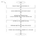
- FIG. 3is a flowchart of an exemplary method for detecting associated devices, consistent with embodiments of the present disclosure
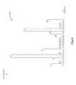
- FIG. 6illustrates an exemplary histogram of matches with candidate devices, consistent with embodiments of the present disclosure.
- Mobile device 102can be a cellular phone, a satellite phone, or any other electronic communication device whose geographic location can be ascertained. Mobile device 102 can communicate with cell towers 104 and/or any other equipment containing antennas, such one or more space satellites. Mobile device 102 can include a Global Positioning System (GPS) module, which enables it to ascertain its geographic location and send information about its geographic location to other devices.
- GPSGlobal Positioning System
- Cellular network 100can include one or more Mobile Switching Centers (MSCs) such as an MSC 106 .
- MSC 106can be connected to one or more cell towers 104 and includes equipment for controlling the cell towers and for routing calls to and from mobile devices 102 wirelessly connected to those cell towers.
- callscan include voice calls, circuit switched data, SMS, conference calls, FAX, and other types of communication data.
- connected tocan be used interchangeably when referring to the exchange of wireless signals between mobile devices 102 and cell towers 104 .
- MSC 106can also be connected to a Public Switched Telephone Network (PSTN) 108 , through which it can receive calls from, and send calls to other devices, such as mobile devices 102 (including mobile devices 102 connected to cell towers 104 that are connected to other MSCs (not shown)), landline telephone sets (not shown), or any other devices that can be connected to PSTN 108 either directly or via additional networks, such as the Internet (not shown).
- PSTNPublic Switched Telephone Network
- Location register 112can store information about one or more mobile devices 102 .
- location register 112can store, for each mobile device 102 , its phone number, its device ID, such as the international mobile subscriber identity (IMSI), the name of its subscriber, a list of subscribed services and features, and the like.
- IMSIinternational mobile subscriber identity
- MSC 106can obtain observation data from other sources, such as one or more communication centers operating a network of satellite phones.
- Location informationcan include a unique “tower ID” of the cell tower to which the mobile device was connected at the time of the observation. Location information can also include the location (e.g., the latitude-longitude coordinates) of the cell tower. In some embodiments, instead of or in addition to the tower ID and/or tower location, location information can include the approximate location (e.g., in latitude-longitude coordinates) of the mobile device itself, as ascertained or obtained by, for example, the mobile device using its GPS module. The approximate location can be obtained, for example, by using any suitable location-determination technique, such as triangulation.
- location register 112can store past observation data for a mobile device. For example, location register 112 can store all observation data that was obtained for that mobile device in the past hour, day, month, year, or any other predefined period of time.
- Location register 112can communicate and exchange data with a data fusion system 200 , either directly (through a wired or wireless connection) or through a network (not shown).
- the networkcan be the Internet, an intranet, a local area network, a wide area network, a campus area network, a metropolitan area network, an extranet, a private extranet, any set of two or more coupled devices, or a combination of any of these or other appropriate networks.
- each property typeis declared to be representative of one or more object types.
- a property typeis representative of an object type when the property type is intuitively associated with the object type. For example, a property type of “Social Security Number” may be representative of an object type “Person” but not representative of an object type “Business.”
- each property typehas one or more components and a base type.
- a property typemay comprise a string, a date, a number, or a composite type consisting of two or more string, date, or number elements.
- property typesare extensible and can represent complex data structures. Further, a parser definition can reference a component of a complex property type as a unit or token.
- An example of a property having multiple componentsis a Name property having a Last Name component and a First Name component.
- An example of raw input datais “Smith, Jane.”
- An example parser definitionspecifies an association of imported input data to object property components as follows: ⁇ LAST_NAME ⁇ , ⁇ FIRST_NAME ⁇ Name:Last, Name:First.
- the association ⁇ LAST_NAME ⁇ , ⁇ FIRST_NAME ⁇is defined in a parser definition using regular expression symbology.
- the association ⁇ LAST_NAME ⁇ , ⁇ FIRST_NAME ⁇indicates that a last name string followed by a first name string comprises valid input data for a property of type Name.
- parsing the input data using the parser definitionresults in assigning the value “Smith” to the Name:Last component of the Name property, and the value “Jane” to the Name:First component of the Name property.
- schema map 240can define how various elements of schemas 235 for data sources 230 map to various elements of ontology 250 .
- Definition component 210receives, calculates, extracts, or otherwise identifies schemas 235 for data sources 230 .
- Schemas 235define the structure of data sources 230 —for example, the names and other characteristics of tables, files, columns, fields, properties, and so forth.
- Definition component 210furthermore optionally identifies sample data 236 from data sources 230 .
- Definition component 210can further identify object type, relationship, and property definitions from ontology 250 , if any already exist.
- Definition component 210can further identify pre-existing mappings from schema map 240 , if such mappings exist.
- definition component 210can generate a graphical interface 215 .
- Graphical interface 215can be presented to users of a computing device via any suitable output mechanism (e.g., a display screen, an image projection, etc.), and can further accept input from users of the computing device via any suitable input mechanism (e.g., a keyboard, a mouse, a touch screen interface).
- Graphical interface 215features a visual workspace that visually depicts representations of the elements of ontology 250 for which mappings are defined in schema map 240 .
- Graphical interface 215also includes controls for adding new elements to schema map 240 and/or ontology 250 , including objects, properties of objects, and relationships, via the visual workspace.
- graphical interface 215can further provide controls in association with the representations that allow for modifying the elements of ontology 250 and identifying how the elements of ontology 250 correspond to elements of schemas 235 .
- the graphical interface 215can further utilize the sample data 236 to provide the user with a preview of object model 260 as the user defines schema map 240 .
- definition component 210can generate and/or modify ontology 250 and schema map 240 .
- graphical interface 215can provide an interface providing a user with the ability to add structure to an unstructured document stored in data sources 230 by tagging one or more portions (e.g., text) within the document. Defining tags and applying these tags to a portion of the document can create object, properties, or links creating a relationship between one or more objects and/or properties.
- portionse.g., text
- Transformation component 220can be invoked after schema map 240 and ontology 250 have been defined or redefined. Transformation component 220 identifies schema map 240 and ontology 250 . Transformation component 220 further reads data sources 230 and identifies schemas 235 for data sources 230 . For each element of ontology 250 described in schema map 240 , transformation component 220 iterates through some or all of the data items of data sources 230 , generating elements of object model 260 in the manner specified by schema map 240 . In some embodiments, transformation component 220 can store a representation of each generated element of object model 260 in a database 270 . In some embodiments, transformation component 220 is further configured to synchronize changes in object model 260 back to data sources 230 .
- Data sources 230can be one or more sources of data, including, without limitation, spreadsheet files, databases, email folders, document collections, media collections, contact directories, and so forth.
- Data sources 230can include structured data (e.g., a database, a .csv file, or any tab delimited or fixed-width file), semi-structured data (e.g., an email, an email server, or forms such as a suspicious activity report or currency transaction report), or unstructured data (e.g., encoded files such as PDF, sound, and image files).
- Data sources 230can include data structures stored persistently in non-volatile memory.
- Data sources 230can also or instead include temporary data structures generated from underlying data sources via data extraction components, such as a result set returned from a database server executing a database query.
- Data sources 230can include or be synchronized with external data sources, such as one or more location registers 112 , each storing information for one or more service providers.
- Object model 260comprises collections of elements such as typed objects, properties, and relationships.
- the collectionscan be structured in any suitable manner.
- a database 270stores the elements of object model 260 , or representations thereof.
- the elements of object model 260are stored within database 270 in a different underlying format, such as in a series of object, property, and relationship tables in a relational database.
- system 200can receive, from location register 112 , observation data, which can then be stored in data sources 230 and transformed into object model 260 , in accordance with the methods described above.
- Observation datacan comprise a plurality of observation entries, also referred to as “observations,” each observation including device information identifying the observed mobile device, location information identifying the location at which the mobile device was observed, and time information identifying the time at which it was observed.
- Device informationcan include any combination of: a phone number associated with the device, a device ID, a name of the user associated with the device, or other types of information identifying the device.
- Location informationcan include a tower ID and/or location of the cell tower that was connected to the mobile device at the time of the observation. As discussed above, location information can also include the approximate location (coordinates) of the mobile device at the time of the observation. Time information can include the date and the time of the observation.
- Observation datacan be unlimited or it can be limited to observations that have occurred within the most recent predefined period of time, for example, within the last day, week, month, etc., in which case older observation entries can be removed from system 200 to save memory space.
- FIG. 3is a flowchart representing an exemplary method 300 for detecting associated devices.
- Method 300can be performed by one or more electronic devices that can be integrated with or remote to data fusion system 200 , but that has access to fusion system 200 . While method 300 and the other following embodiments described herein can be performed by multiple electronic devices, for purposes of simplicity and without limitation, these embodiments will be explained with respect to a single electronic device. While the flowchart discloses the following steps in a particular order, it will be appreciated that at least some of the steps can be moved, modified, or deleted where appropriate, consistent with the teachings of the present disclosure.
- the electronic deviceobtains based on the target device information, observations for the target device.
- the electronic devicecan access data fusion system 200 and obtain from it one or more observation entries whose device information corresponds to the target device.
- the electronic devicecan choose to obtain all observation entries available for the target device, or only a limited set of observation entries, such as observations made within a recent predefined period (e.g., within the last 24 hours, week, month, and the like).
- FIG. 4illustrates an exemplary set of observations obtained for the target device, hereinafter referred to as “target observations.” As illustrated in FIG. 4 , each target observation can include the following information: Device ID, Tower ID, and Timestamp.
- the electronic deviceprocesses each of the observations of the target device (hereinafter, “target observations”) and finds, for each target observation, a set of “matching observations”—observations of other devices that were in the vicinity of the target device at or around the time the target device was observed.
- the electronic devicecan determine a set of one or more “nearby towers”—cell towers located within a predefined distance (e.g., within 3,000 meters) of the cell tower to which the target device was connected, including that cell tower itself.
- the electronic devicecan access a database (e.g., one of data sources 230 of data fusion system 200 or another internal or external database) containing information of all cell towers in the cellular network, the information including, for example, a tower ID and a latitude/longitude location of each cell tower. Based on that information, the electronic device can obtain tower IDs of all towers that are within a predefined distance from the cell tower of the target observation being processed.
- Searching for matching observations some time before and after the time of the target observationcan also be beneficial, because mobile devices do not communicate with a cell tower all the time, and so two or more mobile devices located at the same location do not necessarily connect to the cell tower(s) at exactly the same time.
- step 330after finding all matching observations for the target observation, the electronic device repeats step 330 for the next target observation, and continues to repeat step 330 until all target observations are processed, that is, until matching observations for all target observations are found.
- the electronic deviceobtains, based on the matching observations, a list of unique “candidate devices,” that is, mobile devices that appeared in the matching observations at least once.
- the electronic devicecan determine the list of candidate devices, for example, by retrieving device information (e.g., device ID) from each of the matching observations obtained at step 330 , and adding to the list any device ID that has not yet been added to the list.
- device informatione.g., device ID
- the electronic devicecan calculate the total number of times each candidate device matched the target device, that is, the total number of times each candidate device appeared in the matching observations.
- the electronic devicecan build a histogram or a similar type of data structure that reflects the number of times different candidate devices appeared in the matching observations.
- a fragment of an exemplary histogram 600is illustrated in FIG. 6 .
- sixteen candidate devicesare represented by Device IDs D1-D16.
- histogram 600represents the number of times (N1-N16, respectively) that the candidate device matched the target device.
- the electronic devicecan improve performance and reduce memory requirements by eliminating from the histogram and from further consideration any candidate devices who matched the target device less than a predefined number of times (e.g., less than 10 times).
- the electronic devicecan select from the candidate devices a predefined number of candidate devices with the most matches, and designate those selected devices as associated devices.
- the predefined numbercan be configurable by the user, for example, through graphical interface 215 . For example, referring to the example in FIG. 6 , if the predefined number is 2, the electronic device selects two devices, D4 and D13, as associated devices, because these are the two candidate devices with the highest number of matches.
- the electronic devicecan select one or more candidate devices that have more than a predefined number of matches, and designate those selected devices as associated devices. For example, the electronic device can select all candidate devices that have more than a 1,000 matches with the target device. In some embodiments, the electronic device can first select a predefined number of candidate devices with the most matches, and then eliminate from the selected devices any devices that had less than a predefined number of matches. The electronic device can then designate the remaining selected devices as associated devices.
- the electronic devicecan select associated devices based on one or more other criteria, discussed in detail below.
- the number of unique locationscan be calculated by the electronic device, for example, by counting the number of unique tower IDs within the matching observations of each candidate device.
- the electronic devicecan determine for each matching observation its corresponding target observation, and then count unique tower IDs of the target observations, instead.
- the electronic devicecan determine one or more associated devices based on the time distribution of the matching observations of a candidate device.
- a candidate device matched with the target device at various times during the daye.g., at 5 AM, 11 AM, and at 6 PM
- thismay be a good indication that the same person uses both devices, since they were observed together when the person was likely to be at home and when the person was likely to at work.
- most of the matchesoccur only during one time of the day, for example, only at night time, or only during the day, this may indicate that the devices belong to different people, for example, neighbors or co-workers, respectively, and so the candidate device should not be designated as an associated device.
- the likelihood of a candidate device to be designated as an associated devicecan be increased as the time variability (e.g., the statistical variance among the timestamps) of the matching observations increases, and vice versa.
- the electronic devicecan determine one or more associated devices based on the weekday/weekend distribution of the matching observations of a candidate device.
- a candidate devicematched with the target device on weekends as well as on weekdays, this may be a good indication that the same person uses both devices, whereas when most of the matches occur on weekdays or weekends only, this may indicate that the devices belong to different people. Accordingly, the likelihood of a candidate device to be designated as an associated device can be increased as the weekend/weekday variability of the matching observations increases, and vice versa.
- the electronic devicecan determine one or more associated devices based on the average distance between the cell towers of consecutive matching observations. When the electronic device determines that the average (or median) distance between time-consecutive observations of a candidate device is large (e.g., larger than a predefined threshold), this may indicate that the candidate device is moving fast (and so does the target device), which can be an indication that both devices are located in a moving car (hereinafter referred to as being on a trip).
- the electronic devicecan further determine the lengths of such trips and consider only trips longer than a predefined distance or time, thereby excluding a potential scenario in which the two devices are located in nearby cars that just happen to be driving in the same direction. Because cars are unlikely to drive close to each other for very long distances, if the electronic device determines that the trip was very long (e.g., longer than a predefined distance or time) the two devices are likely to be travelling in the same car. Accordingly, the likelihood of a candidate device to be designated as an associated device can be increased when the electronic device determines that the candidate device matched the target device during a long trip.
- the tripscan be detected by measuring the average (or median) distance between cell towers in consecutive observations, or by measuring the travelling speed of the candidate device—for example, by dividing distance between consecutive observations by the time period between the observations.
- the likelihoodcan be increased with the number as well as the lengths of the trips.
- the electronic devicecan determine associated devices based on any combination of the above-described factors. For example, the electronic device can assign a score to each candidate device, the score being comprised of any combination, such as a weighted combination, of the above-described factors such as a) the total number of matches; b) the number of unique towers; c) the variability of the time distribution; d) the variability of the weekend/weekday distribution; e) the number and the lengths of the trips; and any other factors.
- a weighted combinationsuch as a) the total number of matches; b) the number of unique towers; c) the variability of the time distribution; d) the variability of the weekend/weekday distribution; e) the number and the lengths of the trips; and any other factors.
- the electronic devicecan present information about the determined associated devices to the user, for example, by sending this information to graphical interface 215 .
- the presented information for each associated devicecan include its device ID, phone number, subscriber's name, and the confidence (likelihood) level that the device is used by the same person who uses the target device (as determined, for example, based on a score that is assigned based on the combination of one or more factors described herein).
- the presented informationcan include all matching observations obtained for that device.
- the matching observationscan be presented to the user in association with the corresponding target observations, either in a list, or on a map, or using any other textual and/or graphical representation.
- the usercan further analyze the presented information, determine which, if any, of the associated devices are indeed likely to be used by the user of the target device, and then request (e.g., through graphical interface 215 ) any additional information about those associated devices.
- the electronic devicein addition to or in conjunction with the above-described geolocation-based techniques of determining associated devices, can use the following non-geolocation-based methods to determine associated devices.
- the electronic devicecan access a database (e.g., one of data sources 230 of data fusion system 200 or another internal or external database) that stores subscriber names and devices associated with those subscribers. The electronic device can then find a subscriber based on the target device information received from the user, and then present to the user device information for any other devices associated with the subscriber name.
- a databasee.g., one of data sources 230 of data fusion system 200 or another internal or external database
- the electronic devicecan then find a subscriber based on the target device information received from the user, and then present to the user device information for any other devices associated with the subscriber name.
- the electronic devicecan access a database (e.g., one of data sources 230 of data fusion system 200 or another internal or external database) that stores information on mobile devices and the contacts associated with those devices.
- Contactscan include names and/or phone numbers of people to whom the mobile device has made one or more calls and/or who appear in the mobile device's address book.
- the electronic devicecan determine the contacts of the target device, and find, in the database, other mobile devices that have many (e.g., more than a predefined number) of the same contacts.
- the electronic devicecan access a database (e.g., one of data sources 230 of data fusion system 200 or another internal or external database) that stores information on subscriber identity module (SIM) cards and the device IDs associated with the SIM cards. For example, every time a mobile device places a call, its SIM card information and its device ID are both transmitted to the MSC, which can then transmit that information in the location register, from which the information can be transmitted to data fusion system 200 . If a user removes the SIM card from one device and puts it into a different device, both devices will become associated with the same SIM card in the database. Based on this association, the electronic device can find device ID of one of the devices if given device ID of the other device.
- SIMsubscriber identity module
- the operations, techniques, and/or components described hereincan be implemented by the electronic device, which can include one or more special-purpose computing devices.
- the special-purpose computing devicescan be hard-wired to perform the operations, techniques, and/or components described herein, or can include digital electronic devices such as one or more application-specific integrated circuits (ASICs) or field programmable gate arrays (FPGAs) that are persistently programmed to perform the operations, techniques and/or components described herein, or can include one or more general purpose hardware processors programmed to perform such features of the present disclosure pursuant to program instructions in firmware, memory, other storage, or a combination.
- ASICsapplication-specific integrated circuits
- FPGAsfield programmable gate arrays
- Such special-purpose computing devicescan also combine custom hard-wired logic, ASICs, or FPGAs with custom programming to accomplish the technique and other features of the present disclosure.
- the special-purpose computing devicescan be desktop computer systems, portable computer systems, handheld devices, networking devices, or any other device that incorporates hard-wired and/or program logic to implement the techniques and other features of the present disclosure.
- the one or more special-purpose computing devicescan be generally controlled and coordinated by operating system software, such as iOS, Android, Blackberry, Chrome OS, Windows XP, Windows Vista, Windows 7, Windows 8, Windows Server, Windows CE, Unix, Linux, SunOS, Solaris, VxWorks, or other compatible operating systems.
- operating system softwaresuch as iOS, Android, Blackberry, Chrome OS, Windows XP, Windows Vista, Windows 7, Windows 8, Windows Server, Windows CE, Unix, Linux, SunOS, Solaris, VxWorks, or other compatible operating systems.
- the computing devicecan be controlled by a proprietary operating system.
- Conventional operating systemscontrol and schedule computer processes for execution, perform memory management, provide file system, networking, I/O services, and provide a user interface functionality, such as a graphical user interface (“GUI”), among other things.
- GUIgraphical user interface
- FIG. 7is a block diagram that illustrates an implementation of electronic device 700 , which, as described above, can comprise one or more electronic devices.
- Electronic device 700include a bus 702 or other communication mechanism for communicating information, and one or more hardware processors 704 , coupled with bus 702 for processing information.
- One or more hardware processors 704can be, for example, one or more general purpose microprocessors.
- Electronic device 700also includes a main memory 706 , such as a random access memory (RAM) or other dynamic storage device, coupled to bus 702 for storing information and instructions to be executed by processor 704 .
- Main memory 706also can be used for storing temporary variables or other intermediate information during execution of instructions to be executed by processor 704 .
- Such instructionswhen stored in non-transitory storage media accessible to one or more processors 704 , render electronic device 700 into a special-purpose machine that is customized to perform the operations specified in the instructions.
- Electronic device 700further includes a read only memory (ROM) 708 or other static storage device coupled to bus 702 for storing static information and instructions for processor 704 .
- ROMread only memory
- a storage device 710such as a magnetic disk, optical disk, or USB thumb drive (Flash drive), etc., is provided and coupled to bus 702 for storing information and instructions.
- Electronic device 700can be coupled via bus 702 to a display 712 , such as a cathode ray tube (CRT), an LCD display, or a touchscreen, for displaying information to a computer user.
- a display 712such as a cathode ray tube (CRT), an LCD display, or a touchscreen
- An input device 714is coupled to bus 702 for communicating information and command selections to processor 704 .
- cursor control 716is Another type of user input device, such as a mouse, a trackball, or cursor direction keys for communicating direction information and command selections to processor 704 and for controlling cursor movement on display 712 .
- the input devicetypically has two degrees of freedom in two axes, a first axis (for example, x) and a second axis (for example, y), that allows the device to specify positions in a plane.
- a first axisfor example, x
- a second axisfor example, y
- the same direction information and command selections as cursor controlmay be implemented via receiving touches on a touch screen without a cursor.
- Electronic device 700can include a user interface module to implement a GUI that may be stored in a mass storage device as executable software codes that are executed by the one or more computing devices.
- This and other modulesmay include, by way of example, components, such as software components, object-oriented software components, class components and task components, processes, functions, attributes, procedures, subroutines, segments of program code, drivers, firmware, microcode, circuitry, data, databases, data structures, tables, arrays, and variables.
- modulerefers to logic embodied in hardware or firmware, or to a collection of software instructions, possibly having entry and exit points, written in a programming language, such as, for example, Java, Lua, C or C++.
- a software modulecan be compiled and linked into an executable program, installed in a dynamic link library, or written in an interpreted programming language such as, for example, BASIC, Perl, or Python. It will be appreciated that software modules can be callable from other modules or from themselves, and/or can be invoked in response to detected events or interrupts.
- Software modules configured for execution on computing devicescan be provided on a computer readable medium, such as a compact disc, digital video disc, flash drive, magnetic disc, or any other tangible medium, or as a digital download (and can be originally stored in a compressed or installable format that requires installation, decompression, or decryption prior to execution).
- a computer readable mediumsuch as a compact disc, digital video disc, flash drive, magnetic disc, or any other tangible medium, or as a digital download (and can be originally stored in a compressed or installable format that requires installation, decompression, or decryption prior to execution).
- Such software codecan be stored, partially or fully, on a memory device of the executing computing device, for execution by the computing device.
- Software instructionscan be embedded in firmware, such as an EPROM.
- hardware modulescan be comprised of connected logic units, such as gates and flip-flops, and/or can be comprised of programmable units, such as programmable gate arrays or processors.
- the modules or computing device functionality described hereinare
- Electronic device 700can implement the techniques and other features described herein using customized hard-wired logic, one or more ASICs or FPGAs, firmware and/or program logic which in combination with the electronic device causes or programs electronic device 700 to be a special-purpose machine. According to some embodiments, the techniques and other features described herein are performed by electronic device 700 in response to one or more processors 704 executing one or more sequences of one or more instructions contained in main memory 706 . Such instructions can be read into main memory 706 from another storage medium, such as storage device 710 . Execution of the sequences of instructions contained in main memory 706 causes processor 704 to perform the process steps described herein. In alternative embodiments, hard-wired circuitry can be used in place of or in combination with software instructions.
- non-transitory mediarefers to any media storing data and/or instructions that cause a machine to operate in a specific fashion. Such non-transitory media can comprise non-volatile media and/or volatile media.
- Non-volatile mediaincludes, for example, optical or magnetic disks, such as storage device 710 .
- Volatile mediaincludes dynamic memory, such as main memory 706 .
- non-transitory mediainclude, for example, a floppy disk, a flexible disk, hard disk, solid state drive, magnetic tape, or any other magnetic data storage medium, a CD-ROM, any other optical data storage medium, any physical medium with patterns of holes, a RAM, a PROM, and EPROM, a FLASH-EPROM, NVRAM, any other memory chip or cartridge, and networked versions of the same.
- Non-transitory mediais distinct from, but can be used in conjunction with, transmission media.
- Transmission mediaparticipates in transferring information between storage media.
- transmission mediaincludes coaxial cables, copper wire and fiber optics, including the wires that comprise bus 702 .
- transmission mediacan also take the form of acoustic or light waves, such as those generated during radio-wave and infra-red data communications.
- Various forms of mediacan be involved in carrying one or more sequences of one or more instructions to processor 704 for execution.
- the instructionscan initially be carried on a magnetic disk or solid state drive of a remote computer.
- the remote computercan load the instructions into its dynamic memory and send the instructions over a telephone line using a modem.
- a modem local to electronic device 700can receive the data on the telephone line and use an infra-red transmitter to convert the data to an infra-red signal.
- An infra-red detectorcan receive the data carried in the infra-red signal and appropriate circuitry can place the data on bus 702 .
- Bus 702carries the data to main memory 706 , from which processor 704 retrieves and executes the instructions.
- the instructions received by main memory 706can optionally be stored on storage device 710 either before or after execution by processor 704 .
- Electronic device 700also includes a communication interface 718 coupled to bus 702 .
- Communication interface 718provides a two-way data communication coupling to a network link 720 that is connected to a local network 722 .
- communication interface 718can be an integrated services digital network (ISDN) card, cable modem, satellite modem, or a modem to provide a data communication connection to a corresponding type of telephone line.
- ISDNintegrated services digital network
- communication interface 718can be a local area network (LAN) card to provide a data communication connection to a compatible LAN.
- LANlocal area network
- Wireless linkscan also be implemented.
- communication interface 718sends and receives electrical, electromagnetic or optical signals that carry digital data streams representing various types of information.
- Network link 720typically provides data communication through one or more networks to other data devices.
- network link 720can provide a connection through local network 722 to a host computer 724 or to data equipment operated by an Internet Service Provider (ISP) 726 .
- ISP 726in turn provides data communication services through the world wide packet data communication network now commonly referred to as the “Internet” 728 .
- Internet 728uses electrical, electromagnetic or optical signals that carry digital data streams.
- the signals through the various networks and the signals on network link 720 and through communication interface 718which carry the digital data to and from electronic device 700 , are example forms of transmission media.
- Electronic device 700can send messages and receive data, including program code, through the network(s), network link 720 and communication interface 718 .
- a server 730might transmit a requested code for an application program through Internet 728 , ISP 726 , local network 722 and communication interface 718 .
- the received codecan be executed by processor 704 as it is received, and/or stored in storage device 710 , or other non-volatile storage for later execution.
Landscapes
- Engineering & Computer Science (AREA)
- Evolutionary Computation (AREA)
- Technology Law (AREA)
- Computer Hardware Design (AREA)
- Computer Security & Cryptography (AREA)
- Computing Systems (AREA)
- General Engineering & Computer Science (AREA)
- Computer Networks & Wireless Communication (AREA)
- Signal Processing (AREA)
- Telephone Function (AREA)
Abstract
Description
Claims (20)
Priority Applications (1)
| Application Number | Priority Date | Filing Date | Title |
|---|---|---|---|
| US14/027,118US9313233B2 (en) | 2013-09-13 | 2013-09-13 | Systems and methods for detecting associated devices |
Applications Claiming Priority (1)
| Application Number | Priority Date | Filing Date | Title |
|---|---|---|---|
| US14/027,118US9313233B2 (en) | 2013-09-13 | 2013-09-13 | Systems and methods for detecting associated devices |
Publications (2)
| Publication Number | Publication Date |
|---|---|
| US20150080012A1 US20150080012A1 (en) | 2015-03-19 |
| US9313233B2true US9313233B2 (en) | 2016-04-12 |
Family
ID=52668408
Family Applications (1)
| Application Number | Title | Priority Date | Filing Date |
|---|---|---|---|
| US14/027,118Active2034-03-03US9313233B2 (en) | 2013-09-13 | 2013-09-13 | Systems and methods for detecting associated devices |
Country Status (1)
| Country | Link |
|---|---|
| US (1) | US9313233B2 (en) |
Cited By (13)
| Publication number | Priority date | Publication date | Assignee | Title |
|---|---|---|---|---|
| US9727376B1 (en) | 2014-03-04 | 2017-08-08 | Palantir Technologies, Inc. | Mobile tasks |
| US10037314B2 (en) | 2013-03-14 | 2018-07-31 | Palantir Technologies, Inc. | Mobile reports |
| US10037383B2 (en) | 2013-11-11 | 2018-07-31 | Palantir Technologies, Inc. | Simple web search |
| US10043102B1 (en) | 2016-01-20 | 2018-08-07 | Palantir Technologies Inc. | Database systems and user interfaces for dynamic and interactive mobile image analysis and identification |
| US10111037B1 (en) | 2013-11-22 | 2018-10-23 | Palantir Technologies Inc. | System and method for collocation detection |
| US10187757B1 (en) | 2010-07-12 | 2019-01-22 | Palantir Technologies Inc. | Method and system for determining position of an inertial computing device in a distributed network |
| US10296617B1 (en) | 2015-10-05 | 2019-05-21 | Palantir Technologies Inc. | Searches of highly structured data |
| US10313833B2 (en) | 2013-01-31 | 2019-06-04 | Palantir Technologies Inc. | Populating property values of event objects of an object-centric data model using image metadata |
| US10579647B1 (en) | 2013-12-16 | 2020-03-03 | Palantir Technologies Inc. | Methods and systems for analyzing entity performance |
| US10642853B2 (en) | 2016-12-14 | 2020-05-05 | Palantir Technologies Inc. | Automatically generating graphical data displays based on structured descriptions |
| US10817513B2 (en) | 2013-03-14 | 2020-10-27 | Palantir Technologies Inc. | Fair scheduling for mixed-query loads |
| US11138180B2 (en) | 2011-09-02 | 2021-10-05 | Palantir Technologies Inc. | Transaction protocol for reading database values |
| US11138236B1 (en) | 2017-05-17 | 2021-10-05 | Palantir Technologies Inc. | Systems and methods for packaging information into data objects |
Families Citing this family (3)
| Publication number | Priority date | Publication date | Assignee | Title |
|---|---|---|---|---|
| US9313233B2 (en) | 2013-09-13 | 2016-04-12 | Plantir Technologies Inc. | Systems and methods for detecting associated devices |
| US10103953B1 (en) | 2015-05-12 | 2018-10-16 | Palantir Technologies Inc. | Methods and systems for analyzing entity performance |
| CN109673011B (en)* | 2018-12-03 | 2021-11-26 | 武汉奥浦信息技术有限公司 | Mobile terminal identity information correlation analysis method and device |
Citations (71)
| Publication number | Priority date | Publication date | Assignee | Title |
|---|---|---|---|---|
| US5021792A (en) | 1990-01-12 | 1991-06-04 | Rockwell International Corporation | System for determining direction or attitude using GPS satellite signals |
| US5555503A (en) | 1989-12-11 | 1996-09-10 | Caterpillar Inc. | System and method for providing accurate vehicle positioning using spatial bias techniques |
| US5670987A (en) | 1993-09-21 | 1997-09-23 | Kabushiki Kaisha Toshiba | Virtual manipulating apparatus and method |
| US6141659A (en) | 1998-05-12 | 2000-10-31 | International Businss Machines Corporation | Systems, methods and computer program products for retrieving documents from multiple document servers via a single client session |
| US6189003B1 (en) | 1998-10-23 | 2001-02-13 | Wynwyn.Com Inc. | Online business directory with predefined search template for facilitating the matching of buyers to qualified sellers |
| US6272489B1 (en) | 1998-05-12 | 2001-08-07 | International Business Machines Corp. | Visually oriented, easily navigable search facility |
| US20030152277A1 (en) | 2002-02-13 | 2003-08-14 | Convey Corporation | Method and system for interactive ground-truthing of document images |
| US6642945B1 (en) | 2000-05-04 | 2003-11-04 | Microsoft Corporation | Method and system for optimizing a visual display for handheld computer systems |
| US20030227746A1 (en) | 2002-06-11 | 2003-12-11 | Fujitsu Limited | Functional expansion apparatus and method for attaching electronic apparatus to the functional expansion apparatus |
| WO2004038548A2 (en) | 2002-10-21 | 2004-05-06 | Sinisi John P | System and method for mobile data collection |
| US20040203380A1 (en) | 2000-07-03 | 2004-10-14 | Maher Hamdi | Method and wireless terminal for generating and maintaining a relative positioning system |
| US20050210409A1 (en) | 2004-03-19 | 2005-09-22 | Kenny Jou | Systems and methods for class designation in a computerized social network application |
| US20060116991A1 (en) | 2004-10-13 | 2006-06-01 | Ciphergrid Limited | Remote database technique |
| US20060206235A1 (en) | 2005-03-10 | 2006-09-14 | Shakes Jonathan J | Method and apparatus for multi-destination item selection using motes |
| US20060250764A1 (en) | 2005-05-09 | 2006-11-09 | Apple Computer, Inc. | Universal docking station for hand held electronic devices |
| US20070043744A1 (en) | 2005-08-16 | 2007-02-22 | International Business Machines Corporation | Method and system for linking digital pictures to electronic documents |
| US7188100B2 (en) | 2000-02-25 | 2007-03-06 | Joseph De Bellis | Search-on-the-fly report generator |
| US20070130541A1 (en) | 2004-06-25 | 2007-06-07 | Louch John O | Synchronization of widgets and dashboards |
| US20070198571A1 (en) | 2006-02-03 | 2007-08-23 | Ferguson John R | Data object access system and method using dedicated task object |
| US20070250491A1 (en) | 2002-09-18 | 2007-10-25 | Olszak Artur G | Method for referencing image data |
| US20080007618A1 (en) | 2006-07-05 | 2008-01-10 | Mizuki Yuasa | Vehicle-periphery image generating apparatus and method of switching images |
| US7383053B2 (en) | 2004-04-28 | 2008-06-03 | Lawrence Livermore National Security, Llc | Position estimation of transceivers in communication networks |
| US20090005070A1 (en) | 2007-06-28 | 2009-01-01 | Apple Inc. | Synchronizing mobile and vehicle devices |
| US7523100B1 (en) | 2005-02-28 | 2009-04-21 | Adobe Systems Incorporated | Method and apparatus for using a rendered form as a search template |
| US7529734B2 (en) | 2004-11-12 | 2009-05-05 | Oracle International Corporation | Method and apparatus for facilitating a database query using a query criteria template |
| US20090138790A1 (en) | 2004-04-29 | 2009-05-28 | Microsoft Corporation | Structural editing with schema awareness |
| US20090143052A1 (en) | 2007-11-29 | 2009-06-04 | Michael Bates | Systems and methods for personal information management and contact picture synchronization and distribution |
| US20090156231A1 (en) | 2007-12-13 | 2009-06-18 | Swisscom Ag | System and method for determining a location area of a mobile user |
| US20090265105A1 (en) | 2008-04-21 | 2009-10-22 | Igt | Real-time navigation devices, systems and methods |
| US20090315679A1 (en) | 2008-06-24 | 2009-12-24 | Frederic Bauchot | Location localization method and system |
| US7652622B2 (en) | 2005-04-28 | 2010-01-26 | Cambridge Positioning Systems Limited | Transfer of position information of mobile terminal |
| US20100073315A1 (en) | 2008-09-24 | 2010-03-25 | Samsung Electrronics Co., Ltd. | Mobile terminal and data display method for the same |
| US20100082842A1 (en) | 2008-09-30 | 2010-04-01 | Latista Technologies | Computer program product, system and method for field management and mobile inspection |
| US7706817B2 (en) | 2004-06-15 | 2010-04-27 | Orange Personal Communication Services Limited | Provision of group services in a telecommunications network |
| US7725547B2 (en) | 2006-09-06 | 2010-05-25 | International Business Machines Corporation | Informing a user of gestures made by others out of the user's line of sight |
| US7747648B1 (en) | 2005-02-14 | 2010-06-29 | Yahoo! Inc. | World modeling using a relationship network with communication channels to entities |
| US20100185984A1 (en) | 2008-12-02 | 2010-07-22 | William Wright | System and method for visualizing connected temporal and spatial information as an integrated visual representation on a user interface |
| US20100214117A1 (en) | 2009-02-22 | 2010-08-26 | Verint Systems Ltd. | System and method for predicting future meetings of wireless users |
| US20100223543A1 (en) | 2009-03-02 | 2010-09-02 | International Business Machines Corporation | Automating Interrogative Population of Electronic Forms Using a Real-Time Communication Platform |
| US20100306713A1 (en) | 2009-05-29 | 2010-12-02 | Microsoft Corporation | Gesture Tool |
| US20110022312A1 (en) | 2009-07-23 | 2011-01-27 | Fmr Llc | Generating and Tracking Activity Patterns for Mobile Devices |
| US7945470B1 (en) | 2006-09-29 | 2011-05-17 | Amazon Technologies, Inc. | Facilitating performance of submitted tasks by mobile task performers |
| US20110158469A1 (en) | 2009-12-29 | 2011-06-30 | Mastykarz Justin P | Methods and apparatus for management of field operations, projects and/or collected samples |
| US20110202557A1 (en) | 2010-02-18 | 2011-08-18 | Alon Atsmon | System and method for crowdsourced template based search |
| US8028894B2 (en) | 1999-05-25 | 2011-10-04 | Silverbrook Research Pty Ltd | System for providing information to user with every interaction with printed substrate |
| US20110310005A1 (en) | 2010-06-17 | 2011-12-22 | Qualcomm Incorporated | Methods and apparatus for contactless gesture recognition |
| EP2400448A1 (en) | 2010-06-23 | 2011-12-28 | Quality Inspection Inc. Phoenix | System and method for real time inspection information recording and reporting |
| US20120010812A1 (en) | 2010-07-12 | 2012-01-12 | James Thompson | Method and System for Determining Position of an Inertial Computing Device in a Distributed Network |
| US20120036434A1 (en) | 2010-08-06 | 2012-02-09 | Tavendo Gmbh | Configurable Pie Menu |
| US20120032975A1 (en) | 2006-10-31 | 2012-02-09 | Robert Koch | Location stamping and logging of electronic events and habitat generation |
| US20120150578A1 (en) | 2010-12-08 | 2012-06-14 | Motorola Solutions, Inc. | Task management in a workforce environment using an acoustic map constructed from aggregated audio |
| US20120166929A1 (en) | 2010-12-28 | 2012-06-28 | International Business Machines Corporation | System and method for providing a context-sensitive user interface |
| US20120216106A1 (en) | 2011-02-23 | 2012-08-23 | Casey Martin D | Computer-implemented system and method for conducting field inspections and generating reports |
| US20120268269A1 (en) | 2011-04-19 | 2012-10-25 | Qualcomm Incorporated | Threat score generation |
| US20130013642A1 (en) | 2011-07-05 | 2013-01-10 | Michael Klein | Web based template reporting system |
| US8402047B1 (en) | 2005-02-25 | 2013-03-19 | Adobe Systems Incorporated | Method and apparatus for generating a query to search for matching forms |
| US20130196614A1 (en) | 2012-01-29 | 2013-08-01 | Crimepush Llc | Mobile alert reporting and monitoring systems and methods |
| US8521135B2 (en)* | 2010-12-20 | 2013-08-27 | Research In Motion Limited | Message relay host for delivering messages to out of coverage communications devices |
| US20130235749A1 (en) | 2010-10-22 | 2013-09-12 | Sk Telecom Co., Ltd. | Method device and system for estimating access points using log data |
| US20130262171A1 (en) | 2010-12-10 | 2013-10-03 | Solodko Properties, Llc | System and Method for Directing and Monitoring the Activities of Remote Agents |
| US20130262497A1 (en) | 2012-04-02 | 2013-10-03 | Caterpillar Inc. | Inspection Tool |
| US8739059B2 (en) | 2005-05-16 | 2014-05-27 | Xcira, Inc. | System for generating inspection reports for inspected items |
| US8762870B2 (en) | 2011-07-19 | 2014-06-24 | Salesforce.Com, Inc. | Multifunction drag-and-drop selection tool for selection of data objects in a social network application |
| US20140258827A1 (en) | 2013-03-07 | 2014-09-11 | Ricoh Co., Ltd. | Form Filling Based on Classification and Identification of Multimedia Data |
| US8849254B2 (en)* | 2009-12-18 | 2014-09-30 | Trueposition, Inc. | Location intelligence management system |
| US20140302783A1 (en)* | 2013-03-15 | 2014-10-09 | Whistle Labs, Inc. | Detecting interaction among entities via proximity |
| US20140357299A1 (en) | 2013-05-30 | 2014-12-04 | Hong Kong Baptist University | System and method for providing proximity information |
| EP2816513A1 (en) | 2013-03-14 | 2014-12-24 | Palantir Technologies, Inc. | Mobile reports |
| US20150080012A1 (en) | 2013-09-13 | 2015-03-19 | Palantir Technologies, Inc. | Systems and methods for detecting associated devices |
| US9123086B1 (en) | 2013-01-31 | 2015-09-01 | Palantir Technologies, Inc. | Automatically generating event objects from images |
| EP2916276A1 (en) | 2014-03-04 | 2015-09-09 | Palantir Technologies, Inc. | System including a data repository and a data importing component |
- 2013
- 2013-09-13USUS14/027,118patent/US9313233B2/enactiveActive
Patent Citations (72)
| Publication number | Priority date | Publication date | Assignee | Title |
|---|---|---|---|---|
| US5555503A (en) | 1989-12-11 | 1996-09-10 | Caterpillar Inc. | System and method for providing accurate vehicle positioning using spatial bias techniques |
| US5021792A (en) | 1990-01-12 | 1991-06-04 | Rockwell International Corporation | System for determining direction or attitude using GPS satellite signals |
| US5670987A (en) | 1993-09-21 | 1997-09-23 | Kabushiki Kaisha Toshiba | Virtual manipulating apparatus and method |
| US6141659A (en) | 1998-05-12 | 2000-10-31 | International Businss Machines Corporation | Systems, methods and computer program products for retrieving documents from multiple document servers via a single client session |
| US6272489B1 (en) | 1998-05-12 | 2001-08-07 | International Business Machines Corp. | Visually oriented, easily navigable search facility |
| US6189003B1 (en) | 1998-10-23 | 2001-02-13 | Wynwyn.Com Inc. | Online business directory with predefined search template for facilitating the matching of buyers to qualified sellers |
| US8028894B2 (en) | 1999-05-25 | 2011-10-04 | Silverbrook Research Pty Ltd | System for providing information to user with every interaction with printed substrate |
| US7188100B2 (en) | 2000-02-25 | 2007-03-06 | Joseph De Bellis | Search-on-the-fly report generator |
| US6642945B1 (en) | 2000-05-04 | 2003-11-04 | Microsoft Corporation | Method and system for optimizing a visual display for handheld computer systems |
| US20040203380A1 (en) | 2000-07-03 | 2004-10-14 | Maher Hamdi | Method and wireless terminal for generating and maintaining a relative positioning system |
| US20030152277A1 (en) | 2002-02-13 | 2003-08-14 | Convey Corporation | Method and system for interactive ground-truthing of document images |
| US20030227746A1 (en) | 2002-06-11 | 2003-12-11 | Fujitsu Limited | Functional expansion apparatus and method for attaching electronic apparatus to the functional expansion apparatus |
| US20070250491A1 (en) | 2002-09-18 | 2007-10-25 | Olszak Artur G | Method for referencing image data |
| WO2004038548A2 (en) | 2002-10-21 | 2004-05-06 | Sinisi John P | System and method for mobile data collection |
| US20050210409A1 (en) | 2004-03-19 | 2005-09-22 | Kenny Jou | Systems and methods for class designation in a computerized social network application |
| US7383053B2 (en) | 2004-04-28 | 2008-06-03 | Lawrence Livermore National Security, Llc | Position estimation of transceivers in communication networks |
| US20090138790A1 (en) | 2004-04-29 | 2009-05-28 | Microsoft Corporation | Structural editing with schema awareness |
| US7706817B2 (en) | 2004-06-15 | 2010-04-27 | Orange Personal Communication Services Limited | Provision of group services in a telecommunications network |
| US20070130541A1 (en) | 2004-06-25 | 2007-06-07 | Louch John O | Synchronization of widgets and dashboards |
| US20060116991A1 (en) | 2004-10-13 | 2006-06-01 | Ciphergrid Limited | Remote database technique |
| US7529734B2 (en) | 2004-11-12 | 2009-05-05 | Oracle International Corporation | Method and apparatus for facilitating a database query using a query criteria template |
| US7747648B1 (en) | 2005-02-14 | 2010-06-29 | Yahoo! Inc. | World modeling using a relationship network with communication channels to entities |
| US8402047B1 (en) | 2005-02-25 | 2013-03-19 | Adobe Systems Incorporated | Method and apparatus for generating a query to search for matching forms |
| US7523100B1 (en) | 2005-02-28 | 2009-04-21 | Adobe Systems Incorporated | Method and apparatus for using a rendered form as a search template |
| US20060206235A1 (en) | 2005-03-10 | 2006-09-14 | Shakes Jonathan J | Method and apparatus for multi-destination item selection using motes |
| US7652622B2 (en) | 2005-04-28 | 2010-01-26 | Cambridge Positioning Systems Limited | Transfer of position information of mobile terminal |
| US20060250764A1 (en) | 2005-05-09 | 2006-11-09 | Apple Computer, Inc. | Universal docking station for hand held electronic devices |
| US8739059B2 (en) | 2005-05-16 | 2014-05-27 | Xcira, Inc. | System for generating inspection reports for inspected items |
| US20070043744A1 (en) | 2005-08-16 | 2007-02-22 | International Business Machines Corporation | Method and system for linking digital pictures to electronic documents |
| US20070198571A1 (en) | 2006-02-03 | 2007-08-23 | Ferguson John R | Data object access system and method using dedicated task object |
| US20080007618A1 (en) | 2006-07-05 | 2008-01-10 | Mizuki Yuasa | Vehicle-periphery image generating apparatus and method of switching images |
| US7725547B2 (en) | 2006-09-06 | 2010-05-25 | International Business Machines Corporation | Informing a user of gestures made by others out of the user's line of sight |
| US7945470B1 (en) | 2006-09-29 | 2011-05-17 | Amazon Technologies, Inc. | Facilitating performance of submitted tasks by mobile task performers |
| US20120032975A1 (en) | 2006-10-31 | 2012-02-09 | Robert Koch | Location stamping and logging of electronic events and habitat generation |
| US20090005070A1 (en) | 2007-06-28 | 2009-01-01 | Apple Inc. | Synchronizing mobile and vehicle devices |
| US20090143052A1 (en) | 2007-11-29 | 2009-06-04 | Michael Bates | Systems and methods for personal information management and contact picture synchronization and distribution |
| US20090156231A1 (en) | 2007-12-13 | 2009-06-18 | Swisscom Ag | System and method for determining a location area of a mobile user |
| US20090265105A1 (en) | 2008-04-21 | 2009-10-22 | Igt | Real-time navigation devices, systems and methods |
| US20090315679A1 (en) | 2008-06-24 | 2009-12-24 | Frederic Bauchot | Location localization method and system |
| US20100073315A1 (en) | 2008-09-24 | 2010-03-25 | Samsung Electrronics Co., Ltd. | Mobile terminal and data display method for the same |
| US20100082842A1 (en) | 2008-09-30 | 2010-04-01 | Latista Technologies | Computer program product, system and method for field management and mobile inspection |
| US20100185984A1 (en) | 2008-12-02 | 2010-07-22 | William Wright | System and method for visualizing connected temporal and spatial information as an integrated visual representation on a user interface |
| US20100214117A1 (en) | 2009-02-22 | 2010-08-26 | Verint Systems Ltd. | System and method for predicting future meetings of wireless users |
| US20100223543A1 (en) | 2009-03-02 | 2010-09-02 | International Business Machines Corporation | Automating Interrogative Population of Electronic Forms Using a Real-Time Communication Platform |
| US20100306713A1 (en) | 2009-05-29 | 2010-12-02 | Microsoft Corporation | Gesture Tool |
| US20110022312A1 (en) | 2009-07-23 | 2011-01-27 | Fmr Llc | Generating and Tracking Activity Patterns for Mobile Devices |
| US8849254B2 (en)* | 2009-12-18 | 2014-09-30 | Trueposition, Inc. | Location intelligence management system |
| US20110158469A1 (en) | 2009-12-29 | 2011-06-30 | Mastykarz Justin P | Methods and apparatus for management of field operations, projects and/or collected samples |
| US20110202557A1 (en) | 2010-02-18 | 2011-08-18 | Alon Atsmon | System and method for crowdsourced template based search |
| US20110310005A1 (en) | 2010-06-17 | 2011-12-22 | Qualcomm Incorporated | Methods and apparatus for contactless gesture recognition |
| EP2400448A1 (en) | 2010-06-23 | 2011-12-28 | Quality Inspection Inc. Phoenix | System and method for real time inspection information recording and reporting |
| US9037407B2 (en) | 2010-07-12 | 2015-05-19 | Palantir Technologies Inc. | Method and system for determining position of an inertial computing device in a distributed network |
| US20120010812A1 (en) | 2010-07-12 | 2012-01-12 | James Thompson | Method and System for Determining Position of an Inertial Computing Device in a Distributed Network |
| US20120036434A1 (en) | 2010-08-06 | 2012-02-09 | Tavendo Gmbh | Configurable Pie Menu |
| US20130235749A1 (en) | 2010-10-22 | 2013-09-12 | Sk Telecom Co., Ltd. | Method device and system for estimating access points using log data |
| US20120150578A1 (en) | 2010-12-08 | 2012-06-14 | Motorola Solutions, Inc. | Task management in a workforce environment using an acoustic map constructed from aggregated audio |
| US20130262171A1 (en) | 2010-12-10 | 2013-10-03 | Solodko Properties, Llc | System and Method for Directing and Monitoring the Activities of Remote Agents |
| US8521135B2 (en)* | 2010-12-20 | 2013-08-27 | Research In Motion Limited | Message relay host for delivering messages to out of coverage communications devices |
| US20120166929A1 (en) | 2010-12-28 | 2012-06-28 | International Business Machines Corporation | System and method for providing a context-sensitive user interface |
| US20120216106A1 (en) | 2011-02-23 | 2012-08-23 | Casey Martin D | Computer-implemented system and method for conducting field inspections and generating reports |
| US20120268269A1 (en) | 2011-04-19 | 2012-10-25 | Qualcomm Incorporated | Threat score generation |
| US20130013642A1 (en) | 2011-07-05 | 2013-01-10 | Michael Klein | Web based template reporting system |
| US8762870B2 (en) | 2011-07-19 | 2014-06-24 | Salesforce.Com, Inc. | Multifunction drag-and-drop selection tool for selection of data objects in a social network application |
| US20130196614A1 (en) | 2012-01-29 | 2013-08-01 | Crimepush Llc | Mobile alert reporting and monitoring systems and methods |
| US20130262497A1 (en) | 2012-04-02 | 2013-10-03 | Caterpillar Inc. | Inspection Tool |
| US9123086B1 (en) | 2013-01-31 | 2015-09-01 | Palantir Technologies, Inc. | Automatically generating event objects from images |
| US20140258827A1 (en) | 2013-03-07 | 2014-09-11 | Ricoh Co., Ltd. | Form Filling Based on Classification and Identification of Multimedia Data |
| EP2816513A1 (en) | 2013-03-14 | 2014-12-24 | Palantir Technologies, Inc. | Mobile reports |
| US20140302783A1 (en)* | 2013-03-15 | 2014-10-09 | Whistle Labs, Inc. | Detecting interaction among entities via proximity |
| US20140357299A1 (en) | 2013-05-30 | 2014-12-04 | Hong Kong Baptist University | System and method for providing proximity information |
| US20150080012A1 (en) | 2013-09-13 | 2015-03-19 | Palantir Technologies, Inc. | Systems and methods for detecting associated devices |
| EP2916276A1 (en) | 2014-03-04 | 2015-09-09 | Palantir Technologies, Inc. | System including a data repository and a data importing component |
Non-Patent Citations (26)
| Title |
|---|
| IBM, "Determining Business Object Structure," IBM, 2004, 9 pages. |
| Notice of Allowance for U.S. Appl. No. 13/181,392 dated Jan. 22, 2015. |
| Notice of Allowance for U.S. Appl. No. 13/838,815 dated Jan. 29, 2015. |
| Notice of Allowance for U.S. Appl. No. 13/838,815 dated Jun. 19, 2015. |
| Notice of Allowance for U.S. Appl. No. 14/334,232 dated Nov. 10, 2015. |
| Notice of Allowance for U.S. Appl. No. 14/487,342 dated Sep. 23, 2015. |
| Notice of Allowance for U.S. Appl. No. 14/690,905 dated Nov. 23, 2015. |
| Official Communication for European Patent Application No. 14159447.3 dated Jan. 8, 2015. |
| Official Communication for European Patent Application No. 14159447.3 dated Nov. 26, 2014. |
| Official Communication for European Patent Application No. 15157642.8 dated Jul. 20, 2015. |
| Official Communication for New Zealand Patent Application No. 622501 dated Apr. 1, 2014. |
| Official Communication for New Zealand Patent Application No. 622501 dated Jun. 5, 2014. |
| Official Communication for U.S. Appl. No. 13/181,392 dated Aug. 28, 2014. |
| Official Communication for U.S. Appl. No. 13/831,199 dated Jun. 3, 2015. |
| Official Communication for U.S. Appl. No. 13/831,199 dated Oct. 6, 2015. |
| Official Communication for U.S. Appl. No. 13/839,026 dated Aug. 4, 2015. |
| Official Communication for U.S. Appl. No. 14/088,251 dated Aug. 26, 2015. |
| Official Communication for U.S. Appl. No. 14/088,251 dated Feb. 12, 2015. |
| Official Communication for U.S. Appl. No. 14/088,251 dated Jun. 30, 2015. |
| Official Communication for U.S. Appl. No. 14/088,251 dated May 20, 2015. |
| Official Communication for U.S. Appl. No. 14/196,814 dated May 5, 2015. |
| Official Communication for U.S. Appl. No. 14/196,814 dated Oct. 7, 2015. |
| Official Communication for U.S. Appl. No. 14/334,232 dated Jul. 10, 2015. |
| Official Communication for U.S. Appl. No. 14/487,342 dated Apr. 23, 2015. |
| Official Communication for U.S. Appl. No. 14/690,905 dated Oct. 7, 2015. |
| Restriction Requirement for U.S. Appl. No. 13/839,026 dated Apr. 2, 2015. |
Cited By (20)
| Publication number | Priority date | Publication date | Assignee | Title |
|---|---|---|---|---|
| US10187757B1 (en) | 2010-07-12 | 2019-01-22 | Palantir Technologies Inc. | Method and system for determining position of an inertial computing device in a distributed network |
| US11138180B2 (en) | 2011-09-02 | 2021-10-05 | Palantir Technologies Inc. | Transaction protocol for reading database values |
| US10743133B2 (en) | 2013-01-31 | 2020-08-11 | Palantir Technologies Inc. | Populating property values of event objects of an object-centric data model using image metadata |
| US10313833B2 (en) | 2013-01-31 | 2019-06-04 | Palantir Technologies Inc. | Populating property values of event objects of an object-centric data model using image metadata |
| US10037314B2 (en) | 2013-03-14 | 2018-07-31 | Palantir Technologies, Inc. | Mobile reports |
| US10997363B2 (en) | 2013-03-14 | 2021-05-04 | Palantir Technologies Inc. | Method of generating objects and links from mobile reports |
| US10817513B2 (en) | 2013-03-14 | 2020-10-27 | Palantir Technologies Inc. | Fair scheduling for mixed-query loads |
| US10037383B2 (en) | 2013-11-11 | 2018-07-31 | Palantir Technologies, Inc. | Simple web search |
| US11100174B2 (en) | 2013-11-11 | 2021-08-24 | Palantir Technologies Inc. | Simple web search |
| US10820157B2 (en) | 2013-11-22 | 2020-10-27 | Palantir Technologies Inc. | System and method for collocation detection |
| US10111037B1 (en) | 2013-11-22 | 2018-10-23 | Palantir Technologies Inc. | System and method for collocation detection |
| US10579647B1 (en) | 2013-12-16 | 2020-03-03 | Palantir Technologies Inc. | Methods and systems for analyzing entity performance |
| US10795723B2 (en) | 2014-03-04 | 2020-10-06 | Palantir Technologies Inc. | Mobile tasks |
| US9727376B1 (en) | 2014-03-04 | 2017-08-08 | Palantir Technologies, Inc. | Mobile tasks |
| US10296617B1 (en) | 2015-10-05 | 2019-05-21 | Palantir Technologies Inc. | Searches of highly structured data |
| US10635932B2 (en) | 2016-01-20 | 2020-04-28 | Palantir Technologies Inc. | Database systems and user interfaces for dynamic and interactive mobile image analysis and identification |
| US10339416B2 (en) | 2016-01-20 | 2019-07-02 | Palantir Technologies Inc. | Database systems and user interfaces for dynamic and interactive mobile image analysis and identification |
| US10043102B1 (en) | 2016-01-20 | 2018-08-07 | Palantir Technologies Inc. | Database systems and user interfaces for dynamic and interactive mobile image analysis and identification |
| US10642853B2 (en) | 2016-12-14 | 2020-05-05 | Palantir Technologies Inc. | Automatically generating graphical data displays based on structured descriptions |
| US11138236B1 (en) | 2017-05-17 | 2021-10-05 | Palantir Technologies Inc. | Systems and methods for packaging information into data objects |
Also Published As
| Publication number | Publication date |
|---|---|
| US20150080012A1 (en) | 2015-03-19 |
Similar Documents
| Publication | Publication Date | Title |
|---|---|---|
| US9313233B2 (en) | Systems and methods for detecting associated devices | |
| US9247386B2 (en) | Location-based mobile application and service selection | |
| US20150163626A1 (en) | Monitoring system, server, mobile device and method | |
| Drakonakis et al. | Please forget where I was last summer: The privacy risks of public location (meta) data | |
| US12082074B2 (en) | Alerting users of mobile device using anonymized location and time dataset | |
| US10820157B2 (en) | System and method for collocation detection | |
| US10638270B2 (en) | Location-based wireless tracking | |
| US20110161005A1 (en) | Systems and methods for end-to-end location and media content tracking | |
| CN111782980A (en) | Mining method, device, equipment and storage medium of map interest point | |
| US9418351B2 (en) | Automated network inventory using a user device | |
| CN113593065A (en) | Intelligent attendance processing method and device, computer equipment and storage medium | |
| WO2015105891A1 (en) | Systems and methods for contextual caller identification | |
| US20210258723A1 (en) | Intelligent geofence provisioning | |
| US9832605B1 (en) | Location based services for exigent circumstances | |
| CN108241678B (en) | Method and device for mining point of interest data | |
| CN116668576B (en) | Method, device, cloud management platform, system and storage medium for acquiring data | |
| CN112711710A (en) | Tracking method, system, server and storage medium for multi-number terminal | |
| KR100671164B1 (en) | System and method for providing location information using mobile communication terminal | |
| US10748223B2 (en) | Personal health and safety checks via geolocation expensing | |
| CN111611337B (en) | Terminal data processing system | |
| Schmitt et al. | OTIoT—A browser-based object tracking solution for the Internet of Things | |
| JP2016035679A (en) | POI data generation device, terminal device, POI data generation method and program | |
| CN109639783B (en) | Method, server and client for determining position information | |
| US20160294957A1 (en) | Facilitating users to share physical locations | |
| CN111611336B (en) | Terminal data processing system |
Legal Events
| Date | Code | Title | Description |
|---|---|---|---|
| AS | Assignment | Owner name:PALANTIR TECHNOLOGIES, INC., CALIFORNIA Free format text:ASSIGNMENT OF ASSIGNORS INTEREST;ASSIGNORS:SPRAGUE, MATTHEW;ISAACSON, ANDY;SIGNING DATES FROM 20131009 TO 20131024;REEL/FRAME:031473/0364 | |
| FEPP | Fee payment procedure | Free format text:PAYOR NUMBER ASSIGNED (ORIGINAL EVENT CODE: ASPN); ENTITY STATUS OF PATENT OWNER: LARGE ENTITY | |
| STCF | Information on status: patent grant | Free format text:PATENTED CASE | |
| MAFP | Maintenance fee payment | Free format text:PAYMENT OF MAINTENANCE FEE, 4TH YEAR, LARGE ENTITY (ORIGINAL EVENT CODE: M1551); ENTITY STATUS OF PATENT OWNER: LARGE ENTITY Year of fee payment:4 | |
| AS | Assignment | Owner name:MORGAN STANLEY SENIOR FUNDING, INC., AS ADMINISTRATIVE AGENT, NEW YORK Free format text:SECURITY INTEREST;ASSIGNOR:PALANTIR TECHNOLOGIES INC.;REEL/FRAME:051713/0149 Effective date:20200127 Owner name:ROYAL BANK OF CANADA, AS ADMINISTRATIVE AGENT, CANADA Free format text:SECURITY INTEREST;ASSIGNOR:PALANTIR TECHNOLOGIES INC.;REEL/FRAME:051709/0471 Effective date:20200127 | |
| AS | Assignment | Owner name:PALANTIR TECHNOLOGIES INC., CALIFORNIA Free format text:RELEASE BY SECURED PARTY;ASSIGNOR:ROYAL BANK OF CANADA;REEL/FRAME:052856/0382 Effective date:20200604 Owner name:MORGAN STANLEY SENIOR FUNDING, INC., NEW YORK Free format text:SECURITY INTEREST;ASSIGNOR:PALANTIR TECHNOLOGIES INC.;REEL/FRAME:052856/0817 Effective date:20200604 | |
| AS | Assignment | Owner name:PALANTIR TECHNOLOGIES INC., CALIFORNIA Free format text:CORRECTIVE ASSIGNMENT TO CORRECT THE ERRONEOUSLY LISTED PATENT BY REMOVING APPLICATION NO. 16/832267 FROM THE RELEASE OF SECURITY INTEREST PREVIOUSLY RECORDED ON REEL 052856 FRAME 0382. ASSIGNOR(S) HEREBY CONFIRMS THE RELEASE OF SECURITY INTEREST;ASSIGNOR:ROYAL BANK OF CANADA;REEL/FRAME:057335/0753 Effective date:20200604 | |
| AS | Assignment | Owner name:WELLS FARGO BANK, N.A., NORTH CAROLINA Free format text:ASSIGNMENT OF INTELLECTUAL PROPERTY SECURITY AGREEMENTS;ASSIGNOR:MORGAN STANLEY SENIOR FUNDING, INC.;REEL/FRAME:060572/0640 Effective date:20220701 Owner name:WELLS FARGO BANK, N.A., NORTH CAROLINA Free format text:SECURITY INTEREST;ASSIGNOR:PALANTIR TECHNOLOGIES INC.;REEL/FRAME:060572/0506 Effective date:20220701 | |
| MAFP | Maintenance fee payment | Free format text:PAYMENT OF MAINTENANCE FEE, 8TH YEAR, LARGE ENTITY (ORIGINAL EVENT CODE: M1552); ENTITY STATUS OF PATENT OWNER: LARGE ENTITY Year of fee payment:8 |