US9310608B2 - System and method using a multi-plane curtain - Google Patents
System and method using a multi-plane curtainDownload PDFInfo
- Publication number
- US9310608B2 US9310608B2US13/460,096US201213460096AUS9310608B2US 9310608 B2US9310608 B2US 9310608B2US 201213460096 AUS201213460096 AUS 201213460096AUS 9310608 B2US9310608 B2US 9310608B2
- Authority
- US
- United States
- Prior art keywords
- vehicle
- scanning
- scanner
- mirror block
- range scanner
- Prior art date
- Legal status (The legal status is an assumption and is not a legal conclusion. Google has not performed a legal analysis and makes no representation as to the accuracy of the status listed.)
- Active
Links
- 238000000034methodMethods0.000titleclaimsdescription11
- 230000007246mechanismEffects0.000claimsdescription15
- 238000001514detection methodMethods0.000claimsdescription13
- 230000004044responseEffects0.000claimsdescription12
- 230000001154acute effectEffects0.000claims2
- 239000000463materialSubstances0.000abstractdescription9
- 238000012986modificationMethods0.000description2
- 230000004048modificationEffects0.000description2
- 230000008901benefitEffects0.000description1
- 150000001875compoundsChemical class0.000description1
- 239000011521glassSubstances0.000description1
- 239000002184metalSubstances0.000description1
Images


Classifications
- B—PERFORMING OPERATIONS; TRANSPORTING
- B60—VEHICLES IN GENERAL
- B60R—VEHICLES, VEHICLE FITTINGS, OR VEHICLE PARTS, NOT OTHERWISE PROVIDED FOR
- B60R1/00—Optical viewing arrangements; Real-time viewing arrangements for drivers or passengers using optical image capturing systems, e.g. cameras or video systems specially adapted for use in or on vehicles
- G—PHYSICS
- G01—MEASURING; TESTING
- G01S—RADIO DIRECTION-FINDING; RADIO NAVIGATION; DETERMINING DISTANCE OR VELOCITY BY USE OF RADIO WAVES; LOCATING OR PRESENCE-DETECTING BY USE OF THE REFLECTION OR RERADIATION OF RADIO WAVES; ANALOGOUS ARRANGEMENTS USING OTHER WAVES
- G01S7/00—Details of systems according to groups G01S13/00, G01S15/00, G01S17/00
- G01S7/48—Details of systems according to groups G01S13/00, G01S15/00, G01S17/00 of systems according to group G01S17/00
- G01S7/481—Constructional features, e.g. arrangements of optical elements
- G01S7/4817—Constructional features, e.g. arrangements of optical elements relating to scanning
- B—PERFORMING OPERATIONS; TRANSPORTING
- B60—VEHICLES IN GENERAL
- B60R—VEHICLES, VEHICLE FITTINGS, OR VEHICLE PARTS, NOT OTHERWISE PROVIDED FOR
- B60R11/00—Arrangements for holding or mounting articles, not otherwise provided for
- B60R11/04—Mounting of cameras operative during drive; Arrangement of controls thereof relative to the vehicle
- B—PERFORMING OPERATIONS; TRANSPORTING
- B60—VEHICLES IN GENERAL
- B60W—CONJOINT CONTROL OF VEHICLE SUB-UNITS OF DIFFERENT TYPE OR DIFFERENT FUNCTION; CONTROL SYSTEMS SPECIALLY ADAPTED FOR HYBRID VEHICLES; ROAD VEHICLE DRIVE CONTROL SYSTEMS FOR PURPOSES NOT RELATED TO THE CONTROL OF A PARTICULAR SUB-UNIT
- B60W40/00—Estimation or calculation of non-directly measurable driving parameters for road vehicle drive control systems not related to the control of a particular sub unit, e.g. by using mathematical models
- B60W40/02—Estimation or calculation of non-directly measurable driving parameters for road vehicle drive control systems not related to the control of a particular sub unit, e.g. by using mathematical models related to ambient conditions
- G—PHYSICS
- G01—MEASURING; TESTING
- G01S—RADIO DIRECTION-FINDING; RADIO NAVIGATION; DETERMINING DISTANCE OR VELOCITY BY USE OF RADIO WAVES; LOCATING OR PRESENCE-DETECTING BY USE OF THE REFLECTION OR RERADIATION OF RADIO WAVES; ANALOGOUS ARRANGEMENTS USING OTHER WAVES
- G01S17/00—Systems using the reflection or reradiation of electromagnetic waves other than radio waves, e.g. lidar systems
- G01S17/02—Systems using the reflection of electromagnetic waves other than radio waves
- G01S17/04—Systems determining the presence of a target
- G—PHYSICS
- G01—MEASURING; TESTING
- G01S—RADIO DIRECTION-FINDING; RADIO NAVIGATION; DETERMINING DISTANCE OR VELOCITY BY USE OF RADIO WAVES; LOCATING OR PRESENCE-DETECTING BY USE OF THE REFLECTION OR RERADIATION OF RADIO WAVES; ANALOGOUS ARRANGEMENTS USING OTHER WAVES
- G01S17/00—Systems using the reflection or reradiation of electromagnetic waves other than radio waves, e.g. lidar systems
- G01S17/02—Systems using the reflection of electromagnetic waves other than radio waves
- G01S17/06—Systems determining position data of a target
- G01S17/42—Simultaneous measurement of distance and other co-ordinates
- G—PHYSICS
- G01—MEASURING; TESTING
- G01S—RADIO DIRECTION-FINDING; RADIO NAVIGATION; DETERMINING DISTANCE OR VELOCITY BY USE OF RADIO WAVES; LOCATING OR PRESENCE-DETECTING BY USE OF THE REFLECTION OR RERADIATION OF RADIO WAVES; ANALOGOUS ARRANGEMENTS USING OTHER WAVES
- G01S17/00—Systems using the reflection or reradiation of electromagnetic waves other than radio waves, e.g. lidar systems
- G01S17/87—Combinations of systems using electromagnetic waves other than radio waves
- G—PHYSICS
- G01—MEASURING; TESTING
- G01S—RADIO DIRECTION-FINDING; RADIO NAVIGATION; DETERMINING DISTANCE OR VELOCITY BY USE OF RADIO WAVES; LOCATING OR PRESENCE-DETECTING BY USE OF THE REFLECTION OR RERADIATION OF RADIO WAVES; ANALOGOUS ARRANGEMENTS USING OTHER WAVES
- G01S17/00—Systems using the reflection or reradiation of electromagnetic waves other than radio waves, e.g. lidar systems
- G01S17/88—Lidar systems specially adapted for specific applications
- G01S17/93—Lidar systems specially adapted for specific applications for anti-collision purposes
- G—PHYSICS
- G02—OPTICS
- G02B—OPTICAL ELEMENTS, SYSTEMS OR APPARATUS
- G02B26/00—Optical devices or arrangements for the control of light using movable or deformable optical elements
- G02B26/08—Optical devices or arrangements for the control of light using movable or deformable optical elements for controlling the direction of light
- G02B26/10—Scanning systems
- G02B26/105—Scanning systems with one or more pivoting mirrors or galvano-mirrors
- G—PHYSICS
- G05—CONTROLLING; REGULATING
- G05D—SYSTEMS FOR CONTROLLING OR REGULATING NON-ELECTRIC VARIABLES
- G05D1/00—Control of position, course, altitude or attitude of land, water, air or space vehicles, e.g. using automatic pilots
- G05D1/02—Control of position or course in two dimensions
- G05D1/021—Control of position or course in two dimensions specially adapted to land vehicles
- G05D1/0231—Control of position or course in two dimensions specially adapted to land vehicles using optical position detecting means
- G05D1/0238—Control of position or course in two dimensions specially adapted to land vehicles using optical position detecting means using obstacle or wall sensors
- G01S17/026—
Definitions
- the present inventive conceptsrelate to the field of safety scanning systems and vehicles using the same.
- Material transport vehicles and systemssuch as fork lift trucks, tuggers, and the like, are used in a wide variety of applications.
- Such vehiclescan include manned vehicles and automated guided vehicles (AGVs).
- AGVsautomated guided vehicles
- Some such vehicles and systemscan include sensors and scanners used for navigation and safety.
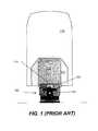
- FIG. 1is a top view and FIG. 2 is a perspective view of a material transport vehicle 100 that includes a bottom laser range scanner 110 and a laser range scanner 104 mounted near a top of the vehicle, in accordance with the prior art. Both of laser scanners 110 and 104 are used for safety.
- a mast 103can be part of or connected to vehicle 100 .
- a light 102is mounted on the mast 103 to communicate signals to nearby individuals, such as signals used for warning and safety purposes.
- the laser scanner 104is also mounted on mast 103 .
- Bottom laser scanner 110is mounted on a front portion of the vehicle 100 at a set height from a ground surface upon which the vehicle travels.
- the bottom laser scanner 110projects a laser beam in front of the vehicle 100 to define two zones, a safety zone 112 and a warning zone 114 . If the bottom laser scanner detects a body or object (collectively “body”) in the safety zone 112 the scanner can send a signal to a controller (not shown) of the vehicle 110 which in turn communicates to the drive mechanisms (also not shown) of the vehicle 110 . In response to receipt of a signal indicating detection of a body in the safety zone 112 , the controller can cause the drive mechanisms to halt movement and/or operation of the vehicle. The controller can also cause light 102 to signal the presence of the condition. In this way, bottom laser scanner can be useful for providing safety relative to a body in front of the vehicle 100 .
- the bottom laser scanner 110can send a signal to the controller.
- the controllerrather than halting operation, could cause the drive mechanism to slow operation and could cause the light 102 to communicate a warning signal. Such detections could also cause audible alarms to be activated.
- laser scanner 104Since the bottom laser scanner 110 projects parallel to the ground surface, objects beneath or above the plane are not detected.
- the use of laser scanner 104enables the safety zone to be extended to a third dimension, because the laser scanner 104 creates a scanning plane that projects from the laser scanner 104 to about a front edge of the safety zone 112 , but also below the plane of the bottom laser scanner 110 to about the ground surface.
- the scanning plane produced by the laser scanner 104is referred to as a “light curtain” 116 .
- laser scanner 104also communicates signals to the controller.
- the controllercan exercise an algorithm for causing the appropriate warning signals and drive mechanism control. For example, the controller can determine what to do if the laser scanner 104 detected a body momentarily, but the bottom scanner 110 never detected a body.
- a multi-plane scanner support systemincludes a bracket and a mirror block.
- the bracketis configured to be secured in a fixed orientation with respect to a scanner; and the mirror block arranged to receive a scanning signal from the scanner and to reflect the scanning signal into a plurality of directions to create multiple scanning planes.
- the scannercan be a laser range scanner.
- the mirror blockcan include a plurality of flat surface, each flat surface arranged to reflect the scanning signal to form a different one of the multiple scanning planes.
- the mirror blockcan include a contoured reflective surface configured to form a bent light curtain comprising the multiple scanning planes.
- the bracket and mirror blockcan be formed as a single unit.
- the mirror blockcan include a plurality of mirrors that receive the scanning signal.
- the plurality of mirrorscan include machined prisms.
- a scanning systemin accordance with another aspect of the present invention, provided is a scanning system.
- the systemincludes a range scanner, bracket, and mirror block.
- the bracketis configured to be secured in a fixed orientation with respect to the range scanner.
- the mirror blockis arranged to receive a scanning signal from the range scanner and to reflect the scanning signal into a plurality of directions to create multiple scanning planes.
- the range scannercan be a laser range scanner.
- the mirror blockcan include a plurality of flat surface, each flat surface arranged to reflect the scanning signal to form a different one of the multiple scanning planes.
- the mirror blockcan include a contoured reflective surface configured to form a bent light curtain comprising the multiple scanning planes.
- the bracket and mirror blockcan be formed as a single unit.
- the mirror blockcan include a plurality of mirrors that receive the scanning signal.
- the plurality of mirrorscan include machined prisms.
- a vehiclehaving a multi-plane scanning system.
- the vehicleincludes a controller operatively coupled to a drive mechanism.
- the multi-plane scanning systemincludes a laser range scanner coupled to the controller; a bracket configured to be secured in a fixed orientation with respect to the laser range scanner; and a mirror block arranged to receive a scanning signal from the laser range scanner and to reflect the scanning signal into a plurality of directions to create multiple scanning planes.
- the laser range scanneris configured to receive a signal from the multiple scanning planes, communicate the signal to the controller as a detection signal, and the controller modifies operation of the vehicle in response to the detection signal.
- the mirror blockcan include a plurality of flat surface, each flat surface arranged to reflect the scanning signal to form a different one of the multiple scanning planes.
- the mirror blockcan include a contoured reflective surface configured to form a bent light curtain comprising the multiple scanning planes.
- the bracket and mirror blockcan be formed as a single unit.
- the mirror blockcan include a plurality of mirrors that receive the scanning signal.
- the plurality of mirrorscan include machined prisms.
- the vehiclecan be an unmanned vehicle.
- the vehiclecan further include a bottom scanner that projects a safety zone and is also coupled to the controller, wherein the safety zone and at least one of the multiple planes intersect.
- FIG. 1is a top view of a material transport vehicle with a prior art laser range scanner system, in accordance with the prior art
- FIG. 2is a perspective view of the prior art system of FIG. 1 ;
- FIG. 3is a top view of a material transport vehicle with an embodiment of a multi-plane laser range scanner system, in accordance with the present invention
- FIG. 4is a perspective view of the system of FIG. 2 , in accordance with aspects of the present invention.
- FIGS. 5A-5Care different views of an embodiment of a laser range scanner and mirror system, in accordance with aspects of the present invention.
- FIG. 6Ais a perspective view of an embodiment of a mirror block, in accordance with aspects of the present invention.
- FIG. 6Bis a perspective view of an embodiment of a bracket that can be used to support the mirror block of FIG. 6A , in accordance with aspects of the present invention.
- spatially relative termssuch as “beneath,” “below,” “lower,” “above,” “upper” and the like may be used to describe an element and/or feature's relationship to another elements) and/or feature(s) as, for example, illustrated in the figures. It will be understood that the spatially relative terms are intended to encompass different orientations of the device in use and/or operation in addition to the orientation depicted in the figures. For example, if the device in the figures is turned over, elements described as “below” and/or “beneath” other elements or features would then be oriented “above” the other elements or features. The device may be otherwise oriented (e.g., rotated 90 degrees or at other orientations) and the spatially relative descriptors used herein interpreted accordingly.
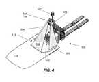
- FIG. 3shows a top view of a material transport vehicle 100 including multi-plane scanner support system 504 and scanner 104 in accordance with aspects of the present invention.
- FIG. 4provides a perspective view of the same arrangement.
- a bottom laser range scanner 110is includes that projects a safety zone 112 and a warning zone 114 .
- a mast 103is included with a light mounted thereto.
- Multi-plane scanner support system 504 and laser scanner 104are also mounted to mast 103 .
- Vehicle 100includes a controller (not shown) to which laser scanner 104 and bottom laser scanner 110 are coupled. And the controller is coupled to a vehicle drive mechanism (not shown) that controls the operation of the vehicle. The controller is also coupled to light 102 , as described with respect to FIGS. 1 and 2 previously described.
- the multi-plane scanner support systemis mounted relative to the scanner 104 such a light curtain 300 having multiple scanning planes 302 , 304 , and 306 , is generated from the single laser 104 . That is, typical lasers used scan a field of view of up to about 270 degrees.
- one or more reflective surfaces of the multi-plane scanner supportreceive the scanning signal in different portions of its scan to create multiple scanning planes 302 , 304 , and 306 .
- a practical benefit of such an approach with material transport vehiclesis that it enables safety zone extension and detection to the front, right, and left areas of the vehicle. This can be extremely useful, for example, when an AGV is navigating around a corner—which are not covered by traditional safety zones and in FIGS. 1 and 2 .
- light curtain 300comprises three relatively discrete scanning planes 302 , 304 and 306 , but in other embodiments a contoured light curtain can be formed using a contoured multi-plane scanner support system 504 .
- laser range scanneris a S100 laser range scanner by SICK, Inc. of Waldkirch, Germany.
- LSM100, S300, and S3000 modelsare other examples of a suitable laser range scanner, also by SICK, Inc.
- the laser scannerpoints about 34 degrees above horizontal and about 66 inches above the ground surface.
- the front plane 302has a field ground projection of about 1100 mm from the front of the vehicle 100 and the side planes 304 , 306 have field ground projections of about 800 mm from the center of the front of the vehicle 100 . These are example, specific dimensions can differ depending, for example, on the vehicle.
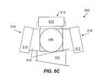
- FIGS. 5A-5Care different views of an embodiment of a laser range scanner and mirror system, in accordance with aspects of the present invention.
- Multi-plane scanner support system 504includes a bracket 510 that has the laser disposed therein, so that reflective surfaces attached to the bracket 510 reflect the laser beam of laser scanner 104 during operation.
- those reflective surfacesare comprised of three mirror blocks 512 , 514 , 516 attached to bracket 510 .
- Each mirror blockincludes a reflective surface 513 , 515 , 517 that receives a scanning signal from the laser 104 .
- Each of reflective surfaces 513 , 515 , 517is used to form a respective scanning plane. For example, surface 513 reflects the laser scanning beam along scanning plane 302 , reflective surface 515 reflects the laser scanning beam along scanning plane 304 , and reflective surface 517 reflects the laser scanning beam along scanning plane 306 in FIGS. 3 and 4 .
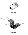
- FIG. 6Ais a perspective view of an embodiment of mirror block 512 and FIG. 6B is a perspective view of an embodiment of a bracket 510 of FIGS. 5A-5C .
- reflective surface 513(not shown in FIG. 6A ) would be attached to a surface A of mirror block 512 .
- the reflective surfacecould take any of a variety of forms, such as a plate made from polished or machined metal or other material (e.g., glass).
- Mirror block 512is mounted to surface 510 a of bracket 510 , shown in FIG. 6B .
- mirror block 514would be mounted to surface 510 b and mirror block 516 would be mounted to surface 510 c.
- two or more of bracket 510 , mirror blocks 512 , 514 , 516 and reflective surfaces 513 , 515 , 517can be made of a single material or compound.
- a contoured reflective surfacecould be used to form a bent light curtain, again having multiple planes. For example, concave curves, convex curve, bends, warps, prisms etc. can be used to tailor the light curtain to have the desired number and shaped plurality of scanning planes.
- the present embodimentsachieve multiple planes without “nodding” mechanisms, are less expensive to make and maintain.
Landscapes
- Physics & Mathematics (AREA)
- Engineering & Computer Science (AREA)
- Electromagnetism (AREA)
- General Physics & Mathematics (AREA)
- Radar, Positioning & Navigation (AREA)
- Remote Sensing (AREA)
- Computer Networks & Wireless Communication (AREA)
- Automation & Control Theory (AREA)
- Aviation & Aerospace Engineering (AREA)
- Mechanical Engineering (AREA)
- Optics & Photonics (AREA)
- Multimedia (AREA)
- Mathematical Physics (AREA)
- Transportation (AREA)
- Optical Radar Systems And Details Thereof (AREA)
- Traffic Control Systems (AREA)
- Control Of Position, Course, Altitude, Or Attitude Of Moving Bodies (AREA)
Abstract
Description
Claims (20)
Priority Applications (2)
| Application Number | Priority Date | Filing Date | Title |
|---|---|---|---|
| US13/460,096US9310608B2 (en) | 2009-08-17 | 2012-04-30 | System and method using a multi-plane curtain |
| US15/096,748US9910137B2 (en) | 2009-08-17 | 2016-04-12 | System and method using a multi-plane curtain |
Applications Claiming Priority (2)
| Application Number | Priority Date | Filing Date | Title |
|---|---|---|---|
| US12/542,279US8169596B2 (en) | 2009-08-17 | 2009-08-17 | System and method using a multi-plane curtain |
| US13/460,096US9310608B2 (en) | 2009-08-17 | 2012-04-30 | System and method using a multi-plane curtain |
Related Parent Applications (1)
| Application Number | Title | Priority Date | Filing Date |
|---|---|---|---|
| US12/542,279ContinuationUS8169596B2 (en) | 2009-08-17 | 2009-08-17 | System and method using a multi-plane curtain |
Related Child Applications (1)
| Application Number | Title | Priority Date | Filing Date |
|---|---|---|---|
| US15/096,748DivisionUS9910137B2 (en) | 2009-08-17 | 2016-04-12 | System and method using a multi-plane curtain |
Publications (2)
| Publication Number | Publication Date |
|---|---|
| US20120218538A1 US20120218538A1 (en) | 2012-08-30 |
| US9310608B2true US9310608B2 (en) | 2016-04-12 |
Family
ID=43588415
Family Applications (3)
| Application Number | Title | Priority Date | Filing Date |
|---|---|---|---|
| US12/542,279Active2030-05-30US8169596B2 (en) | 2009-08-17 | 2009-08-17 | System and method using a multi-plane curtain |
| US13/460,096ActiveUS9310608B2 (en) | 2009-08-17 | 2012-04-30 | System and method using a multi-plane curtain |
| US15/096,748Active2029-08-24US9910137B2 (en) | 2009-08-17 | 2016-04-12 | System and method using a multi-plane curtain |
Family Applications Before (1)
| Application Number | Title | Priority Date | Filing Date |
|---|---|---|---|
| US12/542,279Active2030-05-30US8169596B2 (en) | 2009-08-17 | 2009-08-17 | System and method using a multi-plane curtain |
Family Applications After (1)
| Application Number | Title | Priority Date | Filing Date |
|---|---|---|---|
| US15/096,748Active2029-08-24US9910137B2 (en) | 2009-08-17 | 2016-04-12 | System and method using a multi-plane curtain |
Country Status (6)
| Country | Link |
|---|---|
| US (3) | US8169596B2 (en) |
| EP (1) | EP2467280B1 (en) |
| KR (1) | KR101328484B1 (en) |
| CN (1) | CN102648112B (en) |
| CA (1) | CA2807721C (en) |
| WO (1) | WO2011022303A2 (en) |
Cited By (6)
| Publication number | Priority date | Publication date | Assignee | Title |
|---|---|---|---|---|
| US9910137B2 (en)* | 2009-08-17 | 2018-03-06 | Seegrid Corporation | System and method using a multi-plane curtain |
| US10450001B2 (en) | 2016-08-26 | 2019-10-22 | Crown Equipment Corporation | Materials handling vehicle obstacle scanning tools |
| US10775805B2 (en) | 2016-08-26 | 2020-09-15 | Crown Equipment Limited | Materials handling vehicle path validation and dynamic path modification |
| US10800640B2 (en) | 2016-08-26 | 2020-10-13 | Crown Equipment Corporation | Multi-field scanning tools in materials handling vehicles |
| US11474254B2 (en)* | 2017-11-07 | 2022-10-18 | Piaggio Fast Forward Inc. | Multi-axes scanning system from single-axis scanner |
| WO2023066472A1 (en) | 2021-10-19 | 2023-04-27 | Abb Schweiz Ag | Robotic system comprising an environment sensor |
Families Citing this family (28)
| Publication number | Priority date | Publication date | Assignee | Title |
|---|---|---|---|---|
| JP2012236244A (en)* | 2011-05-10 | 2012-12-06 | Sony Corp | Robot device, method of controlling the same, and program for controlling the same |
| US9181048B1 (en)* | 2011-12-30 | 2015-11-10 | The Rosemyr Corporation | Portable storage container system |
| WO2013112907A1 (en) | 2012-01-25 | 2013-08-01 | Adept Technology, Inc. | Autonomous mobile robot for handling job assignments in a physical environment inhabited by stationary and non-stationary obstacles |
| ES2827192T3 (en) | 2012-02-08 | 2021-05-20 | Omron Tateisi Electronics Co | Task management system for a fleet of autonomous mobile robots |
| JP6255724B2 (en)* | 2013-06-10 | 2018-01-10 | セイコーエプソン株式会社 | Robot and robot operation method |
| KR101551667B1 (en)* | 2013-11-27 | 2015-09-09 | 현대모비스(주) | LIDAR Sensor System |
| US9567102B1 (en)* | 2014-01-29 | 2017-02-14 | Stan W. Ross | Safety system with projectable warning indicia |
| CN104142138B (en)* | 2014-07-15 | 2016-08-24 | 华东建筑设计研究院有限公司 | scanner auxiliary device |
| JP6527941B2 (en)* | 2015-03-23 | 2019-06-12 | 株式会社Fuji | Moving body |
| DE102015105560A1 (en)* | 2015-04-13 | 2016-10-13 | Hamburg Innovation Gmbh | Sensor device with optoelectronic sensor and measuring range extension |
| JP6542574B2 (en)* | 2015-05-12 | 2019-07-10 | 株式会社豊田中央研究所 | forklift |
| CN105606023A (en)* | 2015-12-18 | 2016-05-25 | 武汉万集信息技术有限公司 | Vehicle profile dimensions measuring method and system |
| DE102015226771A1 (en)* | 2015-12-29 | 2017-06-29 | Robert Bosch Gmbh | Deflection device for a lidar sensor |
| JP6754594B2 (en)* | 2016-03-23 | 2020-09-16 | 株式会社小松製作所 | Motor grader |
| EP3269678B1 (en) | 2016-07-14 | 2019-03-06 | Toyota Material Handling Manufacturing Sweden AB | Floor conveyor |
| EP3269680B1 (en)* | 2016-07-14 | 2020-09-30 | Toyota Material Handling Manufacturing Sweden AB | Floor conveyor |
| EP3269679B2 (en)* | 2016-07-14 | 2024-12-04 | Toyota Material Handling Manufacturing Sweden AB | Floor conveyor |
| WO2018182812A2 (en)* | 2016-12-30 | 2018-10-04 | Innovusion Ireland Limited | Multiwavelength lidar design |
| CN110376601B (en)* | 2018-08-14 | 2022-08-12 | 北京京东乾石科技有限公司 | Method and system for determining target pose |
| FR3091525B1 (en) | 2019-01-04 | 2021-01-29 | Balyo | Self-guided handling equipment incorporating detection means |
| US11840436B2 (en) | 2019-04-02 | 2023-12-12 | The Raymond Corporation | Mast and supplementary object detection system for a material handling vehicle |
| CN110515046A (en)* | 2019-07-29 | 2019-11-29 | 上海卫星装备研究所 | Satellite SAR antenna TR channel width phase check device and its operating method |
| WO2021183605A1 (en) | 2020-03-10 | 2021-09-16 | Seegrid Corporation | Self-driving vehicle path adaptation system and method |
| CN112158705B (en)* | 2020-08-31 | 2021-06-29 | 猫岐智能科技(上海)有限公司 | Light curtain imaging method and system, light curtain identification method and system, light curtain device and elevator equipment |
| US20230023551A1 (en)* | 2021-07-20 | 2023-01-26 | Murata Machinery, Ltd. | Autonomous traveling body |
| USD1013000S1 (en) | 2022-03-25 | 2024-01-30 | Seegrid Corporation | Mobile robot |
| WO2024070180A1 (en)* | 2022-09-27 | 2024-04-04 | オプテックス株式会社 | Scan sensor |
| US12292535B2 (en) | 2022-11-08 | 2025-05-06 | Seegrid Corporation | Method and system for calibrating a light-curtain |
Citations (15)
| Publication number | Priority date | Publication date | Assignee | Title |
|---|---|---|---|---|
| US4127771A (en) | 1975-07-21 | 1978-11-28 | Erwin Sick Gesellschaft Mit Beschrankter Haftung Optik-Elektronik | Optical apparatus |
| US4864121A (en) | 1987-03-12 | 1989-09-05 | Erwin Sick Gmbh Optik-Elektronik | Light curtain with periodic light transmitter arrangement |
| US4875761A (en) | 1986-10-16 | 1989-10-24 | Erwin Sick Gmbh Optik-Electronik | Light curtain apparatus |
| US5598263A (en) | 1994-09-13 | 1997-01-28 | Matra Marconi Space France | Light-backscatter measurement device suitable for use on board a craft |
| US5757501A (en) | 1995-08-17 | 1998-05-26 | Hipp; Johann | Apparatus for optically sensing obstacles in front of vehicles |
| US5805275A (en) | 1993-04-08 | 1998-09-08 | Kollmorgen Corporation | Scanning optical rangefinder |
| DE19757848A1 (en) | 1997-12-24 | 1999-07-08 | Johann Hipp | Optical detection apparatus |
| US6317202B1 (en)* | 1998-11-12 | 2001-11-13 | Denso Corporation | Automotive radar detecting lane mark and frontal obstacle |
| US20030116697A1 (en) | 2001-12-20 | 2003-06-26 | Dynapar Corporation | Light curtain mounting system |
| US20050278098A1 (en)* | 1994-05-23 | 2005-12-15 | Automotive Technologies International, Inc. | Vehicular impact reactive system and method |
| US6985212B2 (en)* | 2003-05-19 | 2006-01-10 | Rosemount Aerospace Inc. | Laser perimeter awareness system |
| US7218385B2 (en) | 2004-04-28 | 2007-05-15 | Denso Corporation | Preceding vehicle recognition apparatus |
| US20070181786A1 (en)* | 2004-09-28 | 2007-08-09 | Siemens Aktiengesellschaft | Device for monitoring spatial areas |
| US20110037963A1 (en) | 2009-08-17 | 2011-02-17 | Seegrid Corporation | System and method using a multi-plane curtain |
| US7947944B2 (en)* | 2008-11-03 | 2011-05-24 | Trimble Navigation Limited | Laser transmitter, laser receiver and method |
Family Cites Families (13)
| Publication number | Priority date | Publication date | Assignee | Title |
|---|---|---|---|---|
| JPS5596475A (en)* | 1979-01-19 | 1980-07-22 | Nissan Motor Co Ltd | Obstacle detector for vehicle |
| US6141105A (en)* | 1995-11-17 | 2000-10-31 | Minolta Co., Ltd. | Three-dimensional measuring device and three-dimensional measuring method |
| US7983802B2 (en)* | 1997-10-22 | 2011-07-19 | Intelligent Technologies International, Inc. | Vehicular environment scanning techniques |
| US6252659B1 (en)* | 1998-03-26 | 2001-06-26 | Minolta Co., Ltd. | Three dimensional measurement apparatus |
| US6429941B1 (en)* | 1998-07-14 | 2002-08-06 | Minolta Co., Ltd. | Distance measuring equipment and method |
| KR100470147B1 (en)* | 2002-07-13 | 2005-02-05 | 지오텍컨설탄트 주식회사 | Method for Three-Dimensional Surveying System and Inferring Orientation of Rock-mass Joints Using Reference Coordinate and Laser-Scanner |
| US7076366B2 (en)* | 2002-09-06 | 2006-07-11 | Steven Simon | Object collision avoidance system for a vehicle |
| EP1612509A1 (en)* | 2004-07-01 | 2006-01-04 | Sick IVP AB | Optical profilometer |
| JP4883517B2 (en)* | 2004-11-19 | 2012-02-22 | 学校法人福岡工業大学 | Three-dimensional measuring apparatus, three-dimensional measuring method, and three-dimensional measuring program |
| US20090184811A1 (en)* | 2008-01-23 | 2009-07-23 | Althoff Nicholas K | Methods and system for an impact avoidance system |
| JP5637995B2 (en)* | 2009-10-30 | 2014-12-10 | 株式会社オプトエレクトロニクス | Optical information reader |
| WO2013123600A1 (en)* | 2012-02-21 | 2013-08-29 | Flow-Rite Safety Solutions Inc. | Warning device and collision avoidance system |
| JP6132659B2 (en)* | 2013-02-27 | 2017-05-24 | シャープ株式会社 | Ambient environment recognition device, autonomous mobile system using the same, and ambient environment recognition method |
- 2009
- 2009-08-17USUS12/542,279patent/US8169596B2/enactiveActive
- 2010
- 2010-08-13CNCN201080036411.6Apatent/CN102648112B/ennot_activeExpired - Fee Related
- 2010-08-13WOPCT/US2010/045451patent/WO2011022303A2/enactiveApplication Filing
- 2010-08-13KRKR1020127006927Apatent/KR101328484B1/ennot_activeExpired - Fee Related
- 2010-08-13CACA2807721Apatent/CA2807721C/enactiveActive
- 2010-08-13EPEP10810425.8Apatent/EP2467280B1/enactiveActive
- 2012
- 2012-04-30USUS13/460,096patent/US9310608B2/enactiveActive
- 2016
- 2016-04-12USUS15/096,748patent/US9910137B2/enactiveActive
Patent Citations (16)
| Publication number | Priority date | Publication date | Assignee | Title |
|---|---|---|---|---|
| US4127771A (en) | 1975-07-21 | 1978-11-28 | Erwin Sick Gesellschaft Mit Beschrankter Haftung Optik-Elektronik | Optical apparatus |
| US4875761A (en) | 1986-10-16 | 1989-10-24 | Erwin Sick Gmbh Optik-Electronik | Light curtain apparatus |
| US4864121A (en) | 1987-03-12 | 1989-09-05 | Erwin Sick Gmbh Optik-Elektronik | Light curtain with periodic light transmitter arrangement |
| US5805275A (en) | 1993-04-08 | 1998-09-08 | Kollmorgen Corporation | Scanning optical rangefinder |
| US20050278098A1 (en)* | 1994-05-23 | 2005-12-15 | Automotive Technologies International, Inc. | Vehicular impact reactive system and method |
| US5598263A (en) | 1994-09-13 | 1997-01-28 | Matra Marconi Space France | Light-backscatter measurement device suitable for use on board a craft |
| US5757501A (en) | 1995-08-17 | 1998-05-26 | Hipp; Johann | Apparatus for optically sensing obstacles in front of vehicles |
| DE19757848A1 (en) | 1997-12-24 | 1999-07-08 | Johann Hipp | Optical detection apparatus |
| US6317202B1 (en)* | 1998-11-12 | 2001-11-13 | Denso Corporation | Automotive radar detecting lane mark and frontal obstacle |
| US20030116697A1 (en) | 2001-12-20 | 2003-06-26 | Dynapar Corporation | Light curtain mounting system |
| US6985212B2 (en)* | 2003-05-19 | 2006-01-10 | Rosemount Aerospace Inc. | Laser perimeter awareness system |
| US7218385B2 (en) | 2004-04-28 | 2007-05-15 | Denso Corporation | Preceding vehicle recognition apparatus |
| US20070181786A1 (en)* | 2004-09-28 | 2007-08-09 | Siemens Aktiengesellschaft | Device for monitoring spatial areas |
| US7947944B2 (en)* | 2008-11-03 | 2011-05-24 | Trimble Navigation Limited | Laser transmitter, laser receiver and method |
| US20110037963A1 (en) | 2009-08-17 | 2011-02-17 | Seegrid Corporation | System and method using a multi-plane curtain |
| US8169596B2 (en)* | 2009-08-17 | 2012-05-01 | Seegrid Corporation | System and method using a multi-plane curtain |
Non-Patent Citations (3)
| Title |
|---|
| Extended European Search Report dated Oct. 12, 2012, issued in related European application No. 10810425.8. |
| International Search Report dated Apr. 27, 2011 issued in corresponding International Application No. PCT/US2010/045451. |
| Juberts, Maris, et al, "Status report on next generation LADAR for driving unmanned ground vehicles," NIST, Mobile Robots XVII, 2004, pp. 1-12, SPIE vol. 5609, Bellingham, WA. |
Cited By (12)
| Publication number | Priority date | Publication date | Assignee | Title |
|---|---|---|---|---|
| US9910137B2 (en)* | 2009-08-17 | 2018-03-06 | Seegrid Corporation | System and method using a multi-plane curtain |
| US10450001B2 (en) | 2016-08-26 | 2019-10-22 | Crown Equipment Corporation | Materials handling vehicle obstacle scanning tools |
| US10597074B2 (en) | 2016-08-26 | 2020-03-24 | Crown Equipment Corporation | Materials handling vehicle obstacle scanning tools |
| US10775805B2 (en) | 2016-08-26 | 2020-09-15 | Crown Equipment Limited | Materials handling vehicle path validation and dynamic path modification |
| US10800640B2 (en) | 2016-08-26 | 2020-10-13 | Crown Equipment Corporation | Multi-field scanning tools in materials handling vehicles |
| US11110957B2 (en) | 2016-08-26 | 2021-09-07 | Crown Equipment Corporation | Materials handling vehicle obstacle scanning tools |
| US11294393B2 (en)* | 2016-08-26 | 2022-04-05 | Crown Equipment Corporation | Materials handling vehicle path validation and dynamic path modification |
| US20220253071A1 (en)* | 2016-08-26 | 2022-08-11 | Crown Equipment Corporation | Materials handling vehicle path validation and dynamic path modification |
| US11447377B2 (en) | 2016-08-26 | 2022-09-20 | Crown Equipment Corporation | Multi-field scanning tools in materials handling vehicles |
| US11914394B2 (en)* | 2016-08-26 | 2024-02-27 | Crown Equipment Corporation | Materials handling vehicle path validation and dynamic path modification |
| US11474254B2 (en)* | 2017-11-07 | 2022-10-18 | Piaggio Fast Forward Inc. | Multi-axes scanning system from single-axis scanner |
| WO2023066472A1 (en) | 2021-10-19 | 2023-04-27 | Abb Schweiz Ag | Robotic system comprising an environment sensor |
Also Published As
| Publication number | Publication date |
|---|---|
| WO2011022303A2 (en) | 2011-02-24 |
| EP2467280A4 (en) | 2012-11-14 |
| EP2467280A2 (en) | 2012-06-27 |
| US20120218538A1 (en) | 2012-08-30 |
| KR20120062785A (en) | 2012-06-14 |
| CN102648112B (en) | 2015-01-28 |
| US8169596B2 (en) | 2012-05-01 |
| EP2467280B1 (en) | 2014-11-05 |
| CA2807721C (en) | 2017-11-07 |
| CN102648112A (en) | 2012-08-22 |
| HK1172589A1 (en) | 2013-04-26 |
| KR101328484B1 (en) | 2013-11-13 |
| WO2011022303A3 (en) | 2011-06-23 |
| CA2807721A1 (en) | 2011-02-24 |
| US9910137B2 (en) | 2018-03-06 |
| US20110037963A1 (en) | 2011-02-17 |
| US20160223655A1 (en) | 2016-08-04 |
Similar Documents
| Publication | Publication Date | Title |
|---|---|---|
| US9310608B2 (en) | System and method using a multi-plane curtain | |
| US11669101B1 (en) | Light steering device with an array of oscillating reflective slats | |
| KR102564882B1 (en) | lidar scanning device on car | |
| US9618622B2 (en) | Optical object-detection device having a MEMS and motor vehicle having such a detection device | |
| CN109690347A (en) | Sensing system | |
| US10401865B1 (en) | Light steering device with an array of oscillating reflective slats | |
| KR101878484B1 (en) | Road-shape-recognition front-crash-prevention lidar system | |
| US11474254B2 (en) | Multi-axes scanning system from single-axis scanner | |
| KR101840628B1 (en) | Omnidirectional obstacle detection apparatus, autonomous driving robot using it and omnidirectional obstacle detection method of autonomous driving robot | |
| CN115145273B (en) | Obstacle avoidance control method, robot and computer readable storage medium | |
| KR102317474B1 (en) | Lidar optical apparatus | |
| US20240118389A1 (en) | Curved window for expansion of fov in lidar application | |
| CN109613696B (en) | Optical fiber scanning projection device and electronic equipment | |
| JP2006247803A (en) | Autonomous mobile robot | |
| WO2024076687A1 (en) | Curved window for expansion of fov in lidar application | |
| HK1172589B (en) | System and method using a multi-plane curtain | |
| US12436536B1 (en) | Light steering device with a plurality of beam-steering optics | |
| US20240253254A1 (en) | Robotic System Comprising an Environment Sensor | |
| WO2024049692A1 (en) | Film electromagnetic mirror | |
| WO2025134956A1 (en) | Electromagnetic wave irradiation device |
Legal Events
| Date | Code | Title | Description |
|---|---|---|---|
| AS | Assignment | Owner name:SEEGRID CORPORATION, PENNSYLVANIA Free format text:ASSIGNMENT OF ASSIGNORS INTEREST;ASSIGNORS:WEISS, MITCHELL;BOSWORTH, WILLIAM R.;SIGNING DATES FROM 20100422 TO 20100716;REEL/FRAME:029914/0657 | |
| STCF | Information on status: patent grant | Free format text:PATENTED CASE | |
| AS | Assignment | Owner name:SEEGRID OPERATING CORPORATION, PENNSYLVANIA Free format text:ASSIGNMENT OF ASSIGNORS INTEREST;ASSIGNOR:SEEGRID CORPORATION;REEL/FRAME:038112/0599 Effective date:20151113 | |
| AS | Assignment | Owner name:SEEGRID CORPORATION, PENNSYLVANIA Free format text:CHANGE OF NAME;ASSIGNOR:SEEGRID OPERATING CORPORATION;REEL/FRAME:038914/0191 Effective date:20150126 | |
| MAFP | Maintenance fee payment | Free format text:PAYMENT OF MAINTENANCE FEE, 4TH YR, SMALL ENTITY (ORIGINAL EVENT CODE: M2551); ENTITY STATUS OF PATENT OWNER: SMALL ENTITY Year of fee payment:4 | |
| AS | Assignment | Owner name:SEEGRID CORPORATION, PENNSYLVANIA Free format text:ASSIGNMENT OF ASSIGNORS INTEREST;ASSIGNOR:SEEGRID HOLDING CORPORATION;REEL/FRAME:051675/0817 Effective date:20150126 Owner name:SEEGRID HOLDING CORPORATION, PENNSYLVANIA Free format text:CHANGE OF NAME;ASSIGNOR:SEEGRID CORPORATION;REEL/FRAME:051760/0352 Effective date:20150126 | |
| MAFP | Maintenance fee payment | Free format text:PAYMENT OF MAINTENANCE FEE, 8TH YR, SMALL ENTITY (ORIGINAL EVENT CODE: M2552); ENTITY STATUS OF PATENT OWNER: SMALL ENTITY Year of fee payment:8 |