US9308316B1 - Adapter and syringe for front-loading medical fluid injector - Google Patents
Adapter and syringe for front-loading medical fluid injectorDownload PDFInfo
- Publication number
- US9308316B1 US9308316B1US11/458,463US45846306AUS9308316B1US 9308316 B1US9308316 B1US 9308316B1US 45846306 AUS45846306 AUS 45846306AUS 9308316 B1US9308316 B1US 9308316B1
- Authority
- US
- United States
- Prior art keywords
- injector
- syringe
- injector assembly
- opening
- assembly
- Prior art date
- Legal status (The legal status is an assumption and is not a legal conclusion. Google has not performed a legal analysis and makes no representation as to the accuracy of the status listed.)
- Active, expires
Links
- 239000012530fluidSubstances0.000titleclaimsabstractdescription42
- 238000007789sealingMethods0.000claimsdescription69
- 229940039231contrast mediaDrugs0.000claimsdescription10
- 239000002872contrast mediaSubstances0.000claimsdescription10
- 238000000034methodMethods0.000claimsdescription10
- 230000004323axial lengthEffects0.000claims9
- 238000003384imaging methodMethods0.000claims8
- 230000007246mechanismEffects0.000description11
- 238000002347injectionMethods0.000description5
- 239000007924injectionSubstances0.000description5
- 230000013011matingEffects0.000description4
- 230000002708enhancing effectEffects0.000description2
- 238000003780insertionMethods0.000description2
- 230000037431insertionEffects0.000description2
- 239000000463materialSubstances0.000description2
- 230000004048modificationEffects0.000description2
- 238000012986modificationMethods0.000description2
- 230000036961partial effectEffects0.000description2
- 239000004033plasticSubstances0.000description2
- 230000002829reductive effectEffects0.000description2
- 230000002441reversible effectEffects0.000description2
- 230000002745absorbentEffects0.000description1
- 239000002250absorbentSubstances0.000description1
- 230000008878couplingEffects0.000description1
- 238000010168coupling processMethods0.000description1
- 238000005859coupling reactionMethods0.000description1
- 239000013013elastic materialSubstances0.000description1
- 230000002401inhibitory effectEffects0.000description1
- 238000009434installationMethods0.000description1
- 230000003993interactionEffects0.000description1
- 238000004519manufacturing processMethods0.000description1
- 239000003566sealing materialSubstances0.000description1
- 239000007787solidSubstances0.000description1
Images


Classifications
- A—HUMAN NECESSITIES
- A61—MEDICAL OR VETERINARY SCIENCE; HYGIENE
- A61M—DEVICES FOR INTRODUCING MEDIA INTO, OR ONTO, THE BODY; DEVICES FOR TRANSDUCING BODY MEDIA OR FOR TAKING MEDIA FROM THE BODY; DEVICES FOR PRODUCING OR ENDING SLEEP OR STUPOR
- A61M5/00—Devices for bringing media into the body in a subcutaneous, intra-vascular or intramuscular way; Accessories therefor, e.g. filling or cleaning devices, arm-rests
- A61M5/007—Devices for bringing media into the body in a subcutaneous, intra-vascular or intramuscular way; Accessories therefor, e.g. filling or cleaning devices, arm-rests for contrast media
- A—HUMAN NECESSITIES
- A61—MEDICAL OR VETERINARY SCIENCE; HYGIENE
- A61M—DEVICES FOR INTRODUCING MEDIA INTO, OR ONTO, THE BODY; DEVICES FOR TRANSDUCING BODY MEDIA OR FOR TAKING MEDIA FROM THE BODY; DEVICES FOR PRODUCING OR ENDING SLEEP OR STUPOR
- A61M5/00—Devices for bringing media into the body in a subcutaneous, intra-vascular or intramuscular way; Accessories therefor, e.g. filling or cleaning devices, arm-rests
- A61M5/14—Infusion devices, e.g. infusing by gravity; Blood infusion; Accessories therefor
- A61M5/142—Pressure infusion, e.g. using pumps
- A61M5/145—Pressure infusion, e.g. using pumps using pressurised reservoirs, e.g. pressurised by means of pistons
- A61M5/1452—Pressure infusion, e.g. using pumps using pressurised reservoirs, e.g. pressurised by means of pistons pressurised by means of pistons
- A61M5/14546—Front-loading type injectors
- A—HUMAN NECESSITIES
- A61—MEDICAL OR VETERINARY SCIENCE; HYGIENE
- A61M—DEVICES FOR INTRODUCING MEDIA INTO, OR ONTO, THE BODY; DEVICES FOR TRANSDUCING BODY MEDIA OR FOR TAKING MEDIA FROM THE BODY; DEVICES FOR PRODUCING OR ENDING SLEEP OR STUPOR
- A61M5/00—Devices for bringing media into the body in a subcutaneous, intra-vascular or intramuscular way; Accessories therefor, e.g. filling or cleaning devices, arm-rests
- A61M5/14—Infusion devices, e.g. infusing by gravity; Blood infusion; Accessories therefor
- A61M5/142—Pressure infusion, e.g. using pumps
- A61M5/145—Pressure infusion, e.g. using pumps using pressurised reservoirs, e.g. pressurised by means of pistons
- A61M5/1452—Pressure infusion, e.g. using pumps using pressurised reservoirs, e.g. pressurised by means of pistons pressurised by means of pistons
- A61M2005/14573—Pressure infusion, e.g. using pumps using pressurised reservoirs, e.g. pressurised by means of pistons pressurised by means of pistons with a replaceable reservoir for quick connection/disconnection with a driving system
- A—HUMAN NECESSITIES
- A61—MEDICAL OR VETERINARY SCIENCE; HYGIENE
- A61M—DEVICES FOR INTRODUCING MEDIA INTO, OR ONTO, THE BODY; DEVICES FOR TRANSDUCING BODY MEDIA OR FOR TAKING MEDIA FROM THE BODY; DEVICES FOR PRODUCING OR ENDING SLEEP OR STUPOR
- A61M5/00—Devices for bringing media into the body in a subcutaneous, intra-vascular or intramuscular way; Accessories therefor, e.g. filling or cleaning devices, arm-rests
- A61M5/178—Syringes
- A61M5/24—Ampoule syringes, i.e. syringes with needle for use in combination with replaceable ampoules or carpules, e.g. automatic
- A61M2005/2485—Ampoule holder connected to rest of syringe
- A61M2005/2488—Ampoule holder connected to rest of syringe via rotation, e.g. threads or bayonet
- A—HUMAN NECESSITIES
- A61—MEDICAL OR VETERINARY SCIENCE; HYGIENE
- A61M—DEVICES FOR INTRODUCING MEDIA INTO, OR ONTO, THE BODY; DEVICES FOR TRANSDUCING BODY MEDIA OR FOR TAKING MEDIA FROM THE BODY; DEVICES FOR PRODUCING OR ENDING SLEEP OR STUPOR
- A61M31/00—Devices for introducing or retaining media, e.g. remedies, in cavities of the body
- A61M31/005—Devices for introducing or retaining media, e.g. remedies, in cavities of the body for contrast media
- A—HUMAN NECESSITIES
- A61—MEDICAL OR VETERINARY SCIENCE; HYGIENE
- A61M—DEVICES FOR INTRODUCING MEDIA INTO, OR ONTO, THE BODY; DEVICES FOR TRANSDUCING BODY MEDIA OR FOR TAKING MEDIA FROM THE BODY; DEVICES FOR PRODUCING OR ENDING SLEEP OR STUPOR
- A61M5/00—Devices for bringing media into the body in a subcutaneous, intra-vascular or intramuscular way; Accessories therefor, e.g. filling or cleaning devices, arm-rests
- A61M5/14—Infusion devices, e.g. infusing by gravity; Blood infusion; Accessories therefor
- A61M5/142—Pressure infusion, e.g. using pumps
- A61M5/145—Pressure infusion, e.g. using pumps using pressurised reservoirs, e.g. pressurised by means of pistons
- A61M5/1452—Pressure infusion, e.g. using pumps using pressurised reservoirs, e.g. pressurised by means of pistons pressurised by means of pistons
- A61M5/14566—Pressure infusion, e.g. using pumps using pressurised reservoirs, e.g. pressurised by means of pistons pressurised by means of pistons with a replaceable reservoir for receiving a piston rod of the pump
Definitions
- the present inventionrelates to medical fluid injectors for injecting medical fluid into patients.
- Injectorsare devices that expel fluid, such as contrast media, from a syringe and through a tube into an animal.
- An injectoroften includes an injector unit, usually adjustably fixed to a stand or support, which has a drive ram that couples to the plunger of a syringe to drive the plunger forward to expel fluid into the tube, or to drive the plunger rearward to draw fluid into the syringe to fill it.
- the syringeis disposable.
- U.S. Pat. No. 5,300,031which is assigned to the same assignee as this application, discloses a front-loading injector, and is incorporated by reference herein in its entirety.
- This injectorhas a pressure jacket mounted to its front face for receiving a syringe.
- a syringe having an open back endis inserted into the pressure jacket, and an umbrella surface on the front of the syringe, is coupled to the pressure jacket by a rotating motion.
- This same rotating motioncauses the plunger in the syringe to couple to the end of the ram.
- the pressure jacketsupports the side walls of the syringe against injection pressure during operation of the injector. After an injection, a reverse rotating motion unlocks the syringe from the pressure jacket and releases the plunger from the ram, so the syringe can be removed and replaced.
- a second front-loading injector structureis disclosed in U.S. Pat. No. 5,383,858, which is also incorporated by reference herein in its entirety.
- This front loading injector structureis similar in many respects to that disclosed in U.S. Pat. No. 5,300,031, with the main difference that the injector of the primary figures ( FIGS. 1-8 ) of U.S. Pat. No. 5,383,858, does not include a pressure jacket on the front surface thereof. Rather, the syringe is made of a hard plastic material which is deemed sufficiently self-supporting to withstand injection pressures.
- an injectorincluding an annular, sealing gasket incorporated into the front face of the injector housing, for mating to the rearward circular edge of the cylindrical body of a syringe.
- a locking structure on the outer surface of the syringe and the face of the injectorholds the syringe in tight sealing contact with the gasket on the face of the injector, preventing leakage from the outside surfaces of the syringe into the vicinity of the drive mechanism of the injector.
- the locking structure on the outer surface of the syringecomprises one or more radially extending members, which mate to one or more radially extending members on the face of the injector.
- the members on the face of the injectormay be radially disposed tabs, for receiving flanges on an outer surface of the syringe. The flanges on the syringe are rotated into and out of engagement with the tabs on the face of the injector.
- the tabs on the injectormay form a radially outwardly-facing groove, for receiving a radially inwardly-facing flange on the syringe, or alternatively, the tabs on the injector may have a radially inwardly-facing groove, for receiving a radially outwardly-facing flange on the syringe.
- the face of the injectormay include a slot, for receiving the radially-outwardly extending members on the syringe, by sliding the syringe transversely to its axis, into engagement with the injector.
- the face of the injectormay include a rotating turret, for engaging radially-outwardly extending members on the syringe, and rotating the syringe transversely relative to its axis, into registration with the drive mechanism on the injector.
- the sealing functionis provided by incorporating sealing and locking functions into a single structure on the rearward end of the syringe.
- the end of the syringeincludes a radially outwardly-extending sealing structure, which includes integral locking members for engaging mating structures on the face of the injector.
- these locking membersform a channel in the sealing structure on the syringe, for receiving tabs on an interior surface of the injector housing, so that the sealing structure may be inserted into the housing and rotated to lock the syringe to the injector.
- leakageis prevented by including a non-planar sealing flange on the syringe, positioned on the syringe forward of the locking structure.
- the non-planar sealing flangeincludes a cusp feature for diverting fluid flowing along the surface of the syringe.
- leakageis prevented by a two-piece structure, including a syringe and a separate leakage stopping washer for surrounding the syringe to halt the flow of fluid along the exterior of the syringe.
- a separate unique feature of this aspect of the inventionis the structure of the syringe, which includes an annularly discontinuous flange forward of the locking structure, for providing mechanical support for the syringe against the injector.
- This discontinuous flangenot only provides mechanical support for the syringe when mounted to the injector, but also aids in positioning the leakage stopping washer, which when installed abuts against the annularly discontinuous flange.
- iris-like structureon the front surface of the injector.
- the iris-like structureincludes mechanical actuators for closing the iris-like structure about the syringe upon insertion of the syringe into the injector, thus forming a seal between the syringe and injector.
- the mechanical actuatorsinteract with locking flanges on the rearward surface of the syringe, for translating the iris-like structure into engagement of the syringe upon rotation of the locking flanges on the syringe into the mechanical actuators.
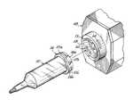
- FIG. 1is a perspective view of a first embodiment of a syringe and a replacement face plate for the injector described in U.S. Pat. No. 5,383,858;
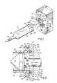
- FIG. 2is a cross-sectional view taken on line 2 - 2 of FIG. 1 , of the syringe and injector of FIG. 1 when coupled together;
- FIG. 3is a perspective view of a second embodiment of a syringe and a replacement face plate for the injector described in U.S. Pat. No. 5,383,858;
- FIG. 4is a perspective view of a third embodiment of a syringe and a replacement face plate for the injector described in U.S. Pat. No. 5,383,858;
- FIG. 5is a perspective view of a fourth embodiment of a syringe and replacement face plate for the injector described in U.S. Pat. No. 5,383,858;
- FIG. 6is a perspective view of a fifth embodiment of a replacement syringe for the injector described in U.S. Pat. No. 5,383,858;
- FIG. 7is a perspective view of a sixth embodiment of a replacement syringe for the injector described in U.S. Pat. No. 5,383,858;
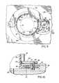
- FIG. 8is partial cut-away front view of a seventh embodiment of a replacement face plate for the injector described in U.S. Pat. No. 5,383,858, showing a sealing mechanism in an open position for receiving a syringe;
- FIG. 9is a view similar to FIG. 8 , showing the sealing mechanism in a closed position as a result of a syringe being mounted thereto;
- FIG. 10is a cross-sectional view taken on line 10 - 10 of FIG. 8 , of the actuating mechanism incorporated in the face plate of FIGS. 8 and 9 ;
- FIG. 11is a partial cut-away front view of an eighth embodiment of a replacement face plate for the injector described in U.S. Pat. No. 5,383,858, showing a sealing mechanism in an open position for receiving a syringe;
- FIG. 12is a view similar to FIG. 11 , showing the sealing mechanism in a closed position as a result of a syringe being mounted thereto.
- the injector disclosed in U.S. Pat. No. 5,383,858is outfitted with a replacement face plate 10 , incorporating features for mounting a syringe 12 .
- Face plate 10includes an opening 11 at a central location thereof.
- the syringe drive ram 13 of the injectorextends through opening 11 to engage the plunger of a syringe mounted to face plate 10 , by a relative rotational motion of the plunger and ram, in the manner described in U.S. Pat. No. 5,383,858.
- Surrounding opening 11is a circular gasket 15 of a flexible material such as rubber.
- syringe 12The structure of syringe 12 is notable in that it does not include a disc-like sealing flange on its exterior. Rather, the exterior surface of cylindrical barrel 14 of the syringe is smooth but for two locking flanges 16 a and 16 b extending from the rearward end of the syringe.
- the syringealso includes, as is conventional, a plunger 19 sealingly engaging an interior of cylindrical barrel 14 and sliding within barrel 14 between an open rearward end of barrel 14 and a closed forward end 18 . Forward end 18 terminates in a discharge extension 20 , to which tubing is mounted to carry injected fluid to a patient.
- a rearward surface of plunger 19includes flanges 21 a and 21 b similar to those described in U.S. Pat. No. 5,383,858, for engaging head 17 of plunger drive ram 13 .
- Flanges 16 a and 16 b on syringe 12are matable to locking structures 22 a and 22 b , respectively, on the front face of face plate 10 .
- face plate 10includes radially outwardly-extending tabs 24 a and 24 b , which form radially outwardly-facing grooves 26 a and 26 b which extend partially annularly about opening 11 in face plate 10 .
- Locking flanges 16 a and 16 b on the rearward end of syringe 12include radially inwardly-extending tabs 28 a and 28 b positioned to interlock into grooves 26 a and 26 b behind tabs 24 a and 24 b.
- a syringeis installed onto injector by first translating the syringe along its axis in the orientation shown in FIG. 1 , until the rearward circular edge 30 of cylindrical barrel 14 of the syringe, engages gasket 15 surrounding opening 11 in face plate 10 . Then, syringe 12 is rotated clockwise to guide tabs 28 a and 28 b on the rearward end of syringe 12 into grooves 26 a and 26 b on face plate 10 . When syringe 12 is rotated ninety degrees clockwise, tab 28 a engages stop 32 a at the end of groove 26 a , thus preventing further clockwise rotation of syringe 12 .
- the diameter of locking structures 22 a and 22 bmay be slightly reduced at their counter-clockwise ends, to facilitate mating of the syringe locking structures 16 a and 16 b to flanges 22 a and 22 b on face plate 10 .
- the thickness of tabs 24 a and 24 bmay be reduced at their counter-clockwise ends (e.g., to the thickness shown in hidden lines at 31 a and 31 b ), to facilitate mating of the syringe locking structures to tabs 24 a and 24 b and to tighten the rearward circular edge 30 of syringe 12 against gasket 15 as the syringe is rotated clockwise into position.
- buttons and detentsmay be incorporated into locking structures 16 a and 16 b and/or flanges 22 a and 22 b , placed so as to interact and provide audible and/or tactile feedback to a user installing a syringe onto face plate 10 , so the user knows when the syringe is properly positioned.
- ninety-degree rotation of syringe 12 into engagement with face plate 10also causes flanges 21 a and 21 b on plunger 19 to engage head 17 on plunger drive ram 13 , so that plunger drive ram 13 can thereafter drive plunger 19 forward and rearward within the cylindrical barrel 14 of the syringe, to perform an injection.
- FIG. 2Also visible in FIG. 2 , is the interaction of the rearward surface 30 of syringe 12 , and gasket 15 .
- gasket 15When syringe 12 is fully installed to face plate 10 , gasket 15 is partially compressed against rearward surface 30 of syringe 12 , so as to form a seal therewith. This seal reduces leakage of injection fluid from the exterior surface of the barrel 14 of syringe 12 , into the area where drive ram 13 exits from face plate 10 .
- This gasketprovides the functions provided by the disc-shaped sealing flange described in the above-noted U.S. Patents, without requiring complex manufacturing or involving breakable parts.
- tabs 24 a , 24 b on the face plate 10may form an inwardly-facing groove such as the groove ( 23 s ) shown in the main figures ( FIGS. 1-8 ) of U.S. Pat. No. 5,383,858 in particular, for mounting to outwardly-projecting structures on syringe 12 .
- the outwardly-projecting locking structures 16 a and 16 b on the rearward end of syringe 12are sized so as to be insertable into the inwardly-facing groove 23 s of the injector described in U.S. Pat. No. 5,383,858, so that syringe 12 may be mounted without modification to the injector of U.S. Pat. No. 5,383,858, or may be mounted to the substitute face plate 10 shown in FIGS. 1 and 2 .
- a replacement face plate 33includes radially inwardly-extending tabs 34 which form an inwardly-facing slot 36 for gripping locking structure on the rearward end of the syringe 12 .
- syringe 35may be mounted by sliding the syringe transversely to its axis, into slot 36 and engagement with tabs 34 .
- the locking structure on the rearward end of syringe 35may include a number of tabs such as are shown in FIGS. 1 and 2 , or may be a continuous, annular flange 38 such as is shown in FIG. 3 .
- the face plate 33 shown in FIG. 3includes a gasket 15 identical in function and placement to the gasket 15 discussed above with reference to FIGS. 1 and 2 .
- Gasket 15forms a seal with the rearward surface of syringe 35 , to form a seal therewith to inhibit the flow of fluid from the exterior of syringe 35 into the region surrounding plunger drive ram 13 .
- flanges 21 a and 21 b on plunger 19are similar to those described above and in U.S. Pat. No. 5,383,858, and are coupled to head 17 of plunger drive ram 13 by rotating syringe 12 after syringe 12 has been fully inserted into slot 36 on face plate 33 .
- Other coupling structurescould also be used, including, for example, a disk-shaped end on drive ram 13 , for engaging flanges 21 a and 21 b upon lateral translation of syringe 35 into slot 36 on face plate 33 , without requiring rotation.
- slot 36 and/or flange 38might include keyed features to require that syringe 35 be placed in a proper rotational orientation before syringe 35 can be slid into slot 36 .
- the opening of slot 36may be slightly narrower than the widest diameter of flange 38
- flange 38might include a flat which must be oriented properly for flange 38 to pass through the narrowed opening of slot 36 and into a mounted position.
- FIG. 4a second alternative structure for mounting a syringe to an injector is shown.
- face plate 39incorporates a turret 40 .
- Turret 40includes two jaws 42 a and 42 b into which one or two syringes can be inserted.
- the syringe 41is similar to the syringe shown in FIG. 3 , in that it includes a continuous, annular flange 43 at its rearward end.
- a gasket(not shown) is incorporated into face plate 39 , surrounding the opening through which the plunger drive ram emerges from the injector, so that the rearward surface of syringe 41 forms a seal therewith to inhibit leakage of spilled fluid into the internal mechanisms of the injector.
- the injectorhas a replacement face plate 48 , for mounting a syringe 50 .
- Syringe 50includes a single-piece, combination locking and sealing structure 54 at its rearward end.
- Structure 54which has a conically-shaped outer surface, has two channels 56 a and 56 b molded therein.
- Each channel 56 a and 56 bincludes an axial opening portion ( 57 a in channel 56 a , not shown in channel 56 b ) and an annular portion ( 59 a in channel 56 a , 59 b in channel 56 b ).
- Face plate 48includes a conically-shaped opening 58 surrounding injector drive ram 13 , which is matable to the conically-shaped outer surface of structure 54 on the rearward end of syringe 50 .
- opening 58Within opening 58 are tabs 60 positioned annularly about an interior of opening 58 and sized to fit into the axial opening portions of channels 56 a and 56 b of syringe structure 54 .
- a gasket(not shown) may also be incorporated into the rim of opening 58 forward of tabs 60 for sealing purposes.
- Syringe 50is installed into injector face plate 48 by inserting structure 54 at the rearward end of syringe 50 into opening 58 , with tabs 60 aligned with the axial opening portions of channels 56 a and 56 b , and then rotating syringe 50 clockwise over an angle of approximately ninety degrees, thus locking tabs 60 into the annular portions 59 a and 59 b of channels 56 a and 56 b .
- a sealis formed between syringe 50 and face plate 48 which inhibits flow of spilled fluid from the exterior of syringe 50 into the mechanism of drive ram 13 .
- a syringesuch as that shown in U.S. Pat. No. 5,383,858 can be improved by enhancing the rigidity of the sealing flange.
- the sealing flangecan be made non-planar, e.g., as shown in FIG. 6 , the sealing flange 64 may be formed with a cusp-shaped feature 66 , thus enhancing the rigidity of the flange while continuing to guide spilled fluid flowing rearwardly along the exterior of the syringe away from the drive mechanism.
- the non-planar sealing flange shown in FIG. 6thus provides the leakage protection function of the planar flange shown in U.S. Pat. No.
- U.S. Pat. No. 5,383,858further indicates that the sealing flange described in that patent stabilizes the syringe while mounted to the injector. This function is also provided by the sealing flange 62 shown in FIG. 6 in that there are substantial annular portions of sealing flange 62 which contact the sealing rim on the injector shown in U.S. Pat. No. 5,383,858, lending the needed stability.
- a syringe 68 for mounting to the injector described in U.S. Pat. No. 5,383,858includes an annular sealing flange which is annularly discontinuous, i.e., separated into segments such as 70.
- An annularly discontinuous flangewhile not necessarily accomplishing the sealing function described in U.S. Pat. No. 5,383,858, does provide stability for the mounted syringe, in that segments 70 contact and form an interference fit with the face of the injector.
- segment 70can be determined based on the stability needed.
- annularly discontinuous segments 70can perhaps be made of more thick layers of plastic, since the gaps between the segments make the segments more able to flex than an annularly continuous flange.
- annular flange formed in segmentsmay be more easily molded than an annularly continuous flange.
- a leakage stopping washer 74may be provided in conjunction with the syringe.
- Washer 74may be formed of solid rubber, sponge rubber, paper or any other absorbent and/or sealing material. Washer 74 may be disposable, and sold with syringe 68 for one-time use, or may be reusable. In either case, washer 74 is slipped over the cylindrical barrel 76 of syringe 68 .
- Washer 74is made of an elastic material and is formed with a slight interference fit relative to the cylindrical barrel 76 of syringe 68 , so that washer 74 forms a seal with barrel 76 to inhibit leakage past washer 74 .
- flange segments 70are used to position washer 74 at the rearward end of syringe 68 so that washer 74 is opposite to the face of the injector when syringe 68 is installed on the injector.
- washer 74may be positioned at any other location along the cylindrical barrel 76 of syringe 68 .
- a sealing functionmay be provided by an iris-like structure on a face plate of the injector, for closing about the syringe to provide a seal between the face plate and outer barrel of the syringe.
- the syringe 78includes a cylindrical barrel 80 , and locking flanges 82 projecting from barrel 80 adjacent a rearward end of the syringe.
- the structure of the syringeis similar to that of the syringe shown in U.S. Pat. No. 5,383,858, with the annular sealing flange removed.
- the syringe 78is mounted into an opening in a replacement face plate 86 mounted on the front face of the injector.
- An opening 88 in the face platepermits the plunger drive ram 13 , and in particular the plunger-mounting head 17 thereof, to emerge from the injector and engage and drive the plunger within the syringe.
- Face plate 86further includes annular grooves of the kind illustrated in U.S. Pat. No. 5,383,858, so that locking flanges 82 of a syringe may be inserted into the face plate 86 in the orientation shown in FIG. 8 , and then rotated into a locked position on the face plate.
- face plate 86includes two sealing arms 90 a and 90 b which, in the open position illustrated in FIG. 8 , permit locking flanges 82 of a syringe to pass into the face plate for locking to the face plate.
- Sealing arms 90 a and 90 bare arcuate sections, having an inside radius of curvature along edges 92 a and 92 b which is approximately equal to the radius of the cylindrical wall 80 of the syringe 78 .
- sealing arms 90 a and 90 bthe motion of sealing arms 90 a and 90 b from their open position of FIG. 8 to their closed position of FIG. 9 can be illustrated. Specifically, when a syringe is inserted into face plate 86 in the orientation shown in FIG. 8 , and then turned clockwise to the orientation shown in FIG. 9 , this rotational motion causes sealing arms 90 a and 90 b to similarly rotate clockwise from the open positions shown in FIG. 8 into the closed positions shown in FIG. 9 . As can be seen in FIG.
- sealing arms 90 a and 90 bengage the outer cylindrical wall 80 of the syringe and form a seal therewith, thus inhibiting leakage of spilled fluid along the wall of the syringe.
- the interior edges 92 a and 92 b of sealing arms 90 a and 90 bmay carry rubber or other flexible seals such as are shown at edges 92 a and 92 b illustrated in FIG. 10 .
- sealing arms 90 a and 90 blend mechanical stability to the syringe when it is mounted on the injector face plate 86 .
- rotation of arms 90 a and 90 bis generated through mechanical mechanisms including a lever arm 94 , which drives a pinion gear 96 , which meshes with a main gear 98 rotationally coupled to the sealing arm 90 .
- Clockwise rotation of the syringe from the position shown in FIG. 8 to the position shown in FIG. 9causes locking flange 82 of the syringe to engage and rotate lever arm 94 counterclockwise.
- Counterclockwise motion of lever arm 94causes counterclockwise motion of pinion gear 96 .
- Pinion gear 96meshing with main gear 98 , causes main gear 98 to rotate clockwise, driving the connected sealing arm to rotate clockwise to its closed position.
- main gear 98is rotationally locked to a shaft 100 , which passes through face plate 86 and into sealing arm.
- rotation of main gear 98causes rotation of shaft 100 and corresponding rotation of sealing arm 90 b .
- a torsion spring 102 coupled between main gear 98 and face plate 86produces a return force tending to rotate main gear 98 , shaft 100 and sealing arm 90 counterclockwise to an open position whenever the syringe is rotated counterclockwise toward its disengaged position.
- sealing arms 101 a and 101 btranslate laterally between their open and closed positions, to provide a sealing function when a syringe is installed to the injector.
- the syringe used in this embodimentis similar to that used in the embodiment of FIGS. 8, 9 and 10 .
- sealing arms 101 a and 101 bare different in structure. Sealing arms 101 a and 101 b include, on their rearward faces, channels 103 a and 103 b , for receiving pins 104 a and 104 b on the face plate 105 of the injector.
- Sealing arms 101 a and 101 btranslate laterally with respect to the axis of the syringe, such that pins 104 a and 104 b slide within channels 103 a and 103 b , guiding the motion of arms 101 a and 101 b .
- Motionis imparted to sealing arms 101 a and 101 b by lever arms 106 a and 106 b , respectively, which pivot about axes 107 a and 107 b , respectively.
- Lever arms 106 a and 106 binclude pins 110 a and 110 b at their exterior ends, which are received into channels 108 a and 108 b on the rearward faces of sealing arms 101 a and 101 b .
- Insertion and rotation of a syringe into a locked position in face plate 105causes rotation of lever arms 106 a and 106 b to close sealing arms 101 a and 101 b .
- a syringeis inserted with locking flanges 82 in the positions shown in FIG. 11 .
- the syringe barrel 80is rotated clockwise approximately ninety degrees, from the orientation shown in FIG. 11 to the orientation shown in FIG. 12 .
- This rotationcauses locking flanges 82 to engage ends 112 a and 112 b of sealing arms 101 a and 101 b , causing counterclockwise rotation of levers 106 a and 106 b about axes 107 a and 107 b , thus bringing sealing arms 101 a and 101 b to their closed positions shown in FIG. 12 .
Landscapes
- Health & Medical Sciences (AREA)
- Vascular Medicine (AREA)
- Engineering & Computer Science (AREA)
- Anesthesiology (AREA)
- Biomedical Technology (AREA)
- Heart & Thoracic Surgery (AREA)
- Hematology (AREA)
- Life Sciences & Earth Sciences (AREA)
- Animal Behavior & Ethology (AREA)
- General Health & Medical Sciences (AREA)
- Public Health (AREA)
- Veterinary Medicine (AREA)
- Infusion, Injection, And Reservoir Apparatuses (AREA)
Abstract
Description
Claims (179)
Priority Applications (3)
| Application Number | Priority Date | Filing Date | Title |
|---|---|---|---|
| US11/458,463US9308316B1 (en) | 1997-07-18 | 2006-07-19 | Adapter and syringe for front-loading medical fluid injector |
| US11/677,946US8932255B1 (en) | 1997-07-18 | 2007-02-22 | Methods for using front-loading medical fluid injector |
| US11/677,926US8864712B1 (en) | 1997-07-18 | 2007-02-22 | Spring loaded medical fluid injector assembly |
Applications Claiming Priority (6)
| Application Number | Priority Date | Filing Date | Title |
|---|---|---|---|
| US89669897A | 1997-07-18 | 1997-07-18 | |
| US89669597A | 1997-07-18 | 1997-07-18 | |
| US09/665,374US6569127B1 (en) | 1997-07-18 | 2000-09-20 | Adapter and syringe for front-loading medical fluid injector |
| US38695703A | 2003-03-12 | 2003-03-12 | |
| US42066406A | 2006-05-26 | 2006-05-26 | |
| US11/458,463US9308316B1 (en) | 1997-07-18 | 2006-07-19 | Adapter and syringe for front-loading medical fluid injector |
Related Parent Applications (1)
| Application Number | Title | Priority Date | Filing Date |
|---|---|---|---|
| US42066406ADivision | 1997-07-18 | 2006-05-26 |
Related Child Applications (2)
| Application Number | Title | Priority Date | Filing Date |
|---|---|---|---|
| US11/677,926DivisionUS8864712B1 (en) | 1997-07-18 | 2007-02-22 | Spring loaded medical fluid injector assembly |
| US11/677,946DivisionUS8932255B1 (en) | 1997-07-18 | 2007-02-22 | Methods for using front-loading medical fluid injector |
Publications (1)
| Publication Number | Publication Date |
|---|---|
| US9308316B1true US9308316B1 (en) | 2016-04-12 |
Family
ID=55643061
Family Applications (1)
| Application Number | Title | Priority Date | Filing Date |
|---|---|---|---|
| US11/458,463Active2025-11-25US9308316B1 (en) | 1997-07-18 | 2006-07-19 | Adapter and syringe for front-loading medical fluid injector |
Country Status (1)
| Country | Link |
|---|---|
| US (1) | US9308316B1 (en) |
Cited By (4)
| Publication number | Priority date | Publication date | Assignee | Title |
|---|---|---|---|---|
| CN106964030A (en)* | 2017-04-19 | 2017-07-21 | 深圳安科高技术股份有限公司 | A kind of piston for injector device |
| WO2020055785A1 (en)* | 2018-09-11 | 2020-03-19 | Bayer Healthcare Llc | Syringe retention feature for fluid injector system |
| CN115697210A (en)* | 2020-03-20 | 2023-02-03 | 巴德外周血管股份有限公司 | Multi-component sealant delivery system with quarter turn connector |
| WO2023052592A1 (en) | 2021-09-30 | 2023-04-06 | Guerbet | Injection device receiving a syringe |
Citations (19)
| Publication number | Priority date | Publication date | Assignee | Title |
|---|---|---|---|---|
| US4345595A (en) | 1979-01-08 | 1982-08-24 | Whitney Douglass G | Piezoelectric fluid injector |
| US4518385A (en) | 1983-06-13 | 1985-05-21 | Preci-Tech Ltd. | Disposable syringe for needleless injector |
| US4685687A (en)* | 1982-08-23 | 1987-08-11 | The S-P Manufacturing Corporation | Workholder |
| US4695271A (en)* | 1986-02-03 | 1987-09-22 | Liebel-Flarsheim Company | Angiographic injector |
| US5007904A (en) | 1989-01-19 | 1991-04-16 | Coeur Laboratories, Inc. | Plunger for power injector angiographic syringe, and syringe comprising same |
| US5098386A (en) | 1991-05-17 | 1992-03-24 | Smith Ina L | Infant nasal suction apparatus |
| US5190523A (en) | 1991-08-16 | 1993-03-02 | Idee International R & D Inc. | Disposable syringe and injector |
| US5201720A (en) | 1992-04-21 | 1993-04-13 | Joseph Borgia | Syringe holding and ejecting assembly |
| US5300031A (en) | 1991-06-07 | 1994-04-05 | Liebel-Flarsheim Company | Apparatus for injecting fluid into animals and disposable front loadable syringe therefor |
| US5383858A (en) | 1992-08-17 | 1995-01-24 | Medrad, Inc. | Front-loading medical injector and syringe for use therewith |
| US5503627A (en)* | 1989-11-09 | 1996-04-02 | Bioject, Inc. | Ampule for needleless injection |
| US5520653A (en) | 1995-09-01 | 1996-05-28 | Medrad, Inc. | Syringe adapter for front-loading medical injector |
| US5535746A (en)* | 1994-03-29 | 1996-07-16 | Sterling Winthrop Inc. | Prefilled syringe for use with power injector |
| US5779675A (en) | 1995-08-25 | 1998-07-14 | Medrad, Inc. | Front load pressure jacket system with syringe holder |
| US5873861A (en) | 1996-11-12 | 1999-02-23 | Medrad, Inc. | Plunger systems |
| US5944694A (en) | 1996-11-12 | 1999-08-31 | Medrad, Inc. | Prefillable syringes and injectors for use therewith |
| US6336913B1 (en) | 1996-03-29 | 2002-01-08 | Medrad, Inc. | Front-loading syringe adapter for front-loading medical injector |
| US6368307B1 (en) | 1997-07-18 | 2002-04-09 | Liebel-Flarsheim Company | Front-loading power injector and method of loading flanged syringe therein |
| US6569127B1 (en) | 1997-07-18 | 2003-05-27 | Liebel-Flarsheim Company | Adapter and syringe for front-loading medical fluid injector |
- 2006
- 2006-07-19USUS11/458,463patent/US9308316B1/enactiveActive
Patent Citations (20)
| Publication number | Priority date | Publication date | Assignee | Title |
|---|---|---|---|---|
| US4345595A (en) | 1979-01-08 | 1982-08-24 | Whitney Douglass G | Piezoelectric fluid injector |
| US4685687A (en)* | 1982-08-23 | 1987-08-11 | The S-P Manufacturing Corporation | Workholder |
| US4518385A (en) | 1983-06-13 | 1985-05-21 | Preci-Tech Ltd. | Disposable syringe for needleless injector |
| US4695271A (en)* | 1986-02-03 | 1987-09-22 | Liebel-Flarsheim Company | Angiographic injector |
| US5007904A (en) | 1989-01-19 | 1991-04-16 | Coeur Laboratories, Inc. | Plunger for power injector angiographic syringe, and syringe comprising same |
| US5503627A (en)* | 1989-11-09 | 1996-04-02 | Bioject, Inc. | Ampule for needleless injection |
| US5098386A (en) | 1991-05-17 | 1992-03-24 | Smith Ina L | Infant nasal suction apparatus |
| US5300031A (en) | 1991-06-07 | 1994-04-05 | Liebel-Flarsheim Company | Apparatus for injecting fluid into animals and disposable front loadable syringe therefor |
| US5190523A (en) | 1991-08-16 | 1993-03-02 | Idee International R & D Inc. | Disposable syringe and injector |
| US5201720A (en) | 1992-04-21 | 1993-04-13 | Joseph Borgia | Syringe holding and ejecting assembly |
| US5383858B1 (en) | 1992-08-17 | 1996-10-29 | Medrad Inc | Front-loading medical injector and syringe for use therewith |
| US5383858A (en) | 1992-08-17 | 1995-01-24 | Medrad, Inc. | Front-loading medical injector and syringe for use therewith |
| US5535746A (en)* | 1994-03-29 | 1996-07-16 | Sterling Winthrop Inc. | Prefilled syringe for use with power injector |
| US5779675A (en) | 1995-08-25 | 1998-07-14 | Medrad, Inc. | Front load pressure jacket system with syringe holder |
| US5520653A (en) | 1995-09-01 | 1996-05-28 | Medrad, Inc. | Syringe adapter for front-loading medical injector |
| US6336913B1 (en) | 1996-03-29 | 2002-01-08 | Medrad, Inc. | Front-loading syringe adapter for front-loading medical injector |
| US5873861A (en) | 1996-11-12 | 1999-02-23 | Medrad, Inc. | Plunger systems |
| US5944694A (en) | 1996-11-12 | 1999-08-31 | Medrad, Inc. | Prefillable syringes and injectors for use therewith |
| US6368307B1 (en) | 1997-07-18 | 2002-04-09 | Liebel-Flarsheim Company | Front-loading power injector and method of loading flanged syringe therein |
| US6569127B1 (en) | 1997-07-18 | 2003-05-27 | Liebel-Flarsheim Company | Adapter and syringe for front-loading medical fluid injector |
Cited By (5)
| Publication number | Priority date | Publication date | Assignee | Title |
|---|---|---|---|---|
| CN106964030A (en)* | 2017-04-19 | 2017-07-21 | 深圳安科高技术股份有限公司 | A kind of piston for injector device |
| WO2020055785A1 (en)* | 2018-09-11 | 2020-03-19 | Bayer Healthcare Llc | Syringe retention feature for fluid injector system |
| CN112912119A (en)* | 2018-09-11 | 2021-06-04 | 拜耳医药保健有限责任公司 | Syringe securement features for fluid injector systems |
| CN115697210A (en)* | 2020-03-20 | 2023-02-03 | 巴德外周血管股份有限公司 | Multi-component sealant delivery system with quarter turn connector |
| WO2023052592A1 (en) | 2021-09-30 | 2023-04-06 | Guerbet | Injection device receiving a syringe |
Similar Documents
| Publication | Publication Date | Title |
|---|---|---|
| US8597246B1 (en) | Front loaded medical fluid syringe mounting | |
| JP3648254B2 (en) | Prefillable syringes and plungers and injectors used with them | |
| US6676634B1 (en) | Front-loading syringe adapter for front-loading medical injector | |
| US7081104B2 (en) | Method and apparatus for injecting fluid into animals and disposable front loadable syringe therefor | |
| US6562008B1 (en) | Front loading medical injector and syringe for use therewith | |
| US8262644B2 (en) | Disposable front loadable syringe and injector | |
| US5520653A (en) | Syringe adapter for front-loading medical injector | |
| US6764466B1 (en) | Adapter and syringe for front-loading medical fluid injector | |
| US6402718B1 (en) | Front-loading medical injector and syringe for use therewith | |
| US9308316B1 (en) | Adapter and syringe for front-loading medical fluid injector | |
| JP4567149B2 (en) | Chemical injection system | |
| US6322535B1 (en) | Prefillable syringes and injectors for use therewith | |
| US6017330A (en) | Plunger systems | |
| CN100366309C (en) | Needleless luer activated medical connector | |
| US6533758B1 (en) | Adapter and syringe for front-loading medical fluid injector | |
| US20040122370A1 (en) | Front load pressure jacket system with pivotal locking members | |
| EP2114493A1 (en) | Universal adapter for a syringe plunger | |
| CN1829551A (en) | Connection system for medical use | |
| JP7573162B2 (en) | Medical Connectors |
Legal Events
| Date | Code | Title | Description |
|---|---|---|---|
| AS | Assignment | Owner name:DEUTSCHE BANK AG NEW YORK BRANCH, NEW YORK Free format text:SECURITY INTEREST;ASSIGNORS:MALLINCKRODT INTERNATIONAL FINANCE S.A.;MALLINCKRODT CB LLC;MALLINCKRODT FINANCE GMBH;AND OTHERS;REEL/FRAME:032480/0001 Effective date:20140319 | |
| AS | Assignment | Owner name:LIEBEL-FLARSHEIM COMPANY LLC, OHIO Free format text:RELEASE BY SECURED PARTY;ASSIGNOR:DEUTSCHE BANK AG NEW YORK BRANCH, AS COLLATERAL AGENT;REEL/FRAME:037172/0094 Effective date:20151127 | |
| STCF | Information on status: patent grant | Free format text:PATENTED CASE | |
| CC | Certificate of correction | ||
| MAFP | Maintenance fee payment | Free format text:PAYMENT OF MAINTENANCE FEE, 4TH YEAR, LARGE ENTITY (ORIGINAL EVENT CODE: M1551); ENTITY STATUS OF PATENT OWNER: LARGE ENTITY Year of fee payment:4 | |
| MAFP | Maintenance fee payment | Free format text:PAYMENT OF MAINTENANCE FEE, 8TH YEAR, LARGE ENTITY (ORIGINAL EVENT CODE: M1552); ENTITY STATUS OF PATENT OWNER: LARGE ENTITY Year of fee payment:8 | |
| AS | Assignment | Owner name:INO THERAPEUTICS LLC, MISSOURI Free format text:RELEASE OF PATENT SECURITY INTERESTS RECORDED AT REEL 032480, FRAME 0001;ASSIGNOR:DEUTSCHE BANK AG NEW YORK BRANCH, AS COLLATERAL AGENT;REEL/FRAME:065609/0322 Effective date:20231114 Owner name:IKARIA THERAPEUTICS LLC, NEW JERSEY Free format text:RELEASE OF PATENT SECURITY INTERESTS RECORDED AT REEL 032480, FRAME 0001;ASSIGNOR:DEUTSCHE BANK AG NEW YORK BRANCH, AS COLLATERAL AGENT;REEL/FRAME:065609/0322 Effective date:20231114 Owner name:THERAKOS, INC., MISSOURI Free format text:RELEASE OF PATENT SECURITY INTERESTS RECORDED AT REEL 032480, FRAME 0001;ASSIGNOR:DEUTSCHE BANK AG NEW YORK BRANCH, AS COLLATERAL AGENT;REEL/FRAME:065609/0322 Effective date:20231114 Owner name:ST SHARED SERVICES LLC, MISSOURI Free format text:RELEASE OF PATENT SECURITY INTERESTS RECORDED AT REEL 032480, FRAME 0001;ASSIGNOR:DEUTSCHE BANK AG NEW YORK BRANCH, AS COLLATERAL AGENT;REEL/FRAME:065609/0322 Effective date:20231114 Owner name:INFACARE PHARMACEUTICAL CORPORATION, MISSOURI Free format text:RELEASE OF PATENT SECURITY INTERESTS RECORDED AT REEL 032480, FRAME 0001;ASSIGNOR:DEUTSCHE BANK AG NEW YORK BRANCH, AS COLLATERAL AGENT;REEL/FRAME:065609/0322 Effective date:20231114 Owner name:MALLINCKRODT PHARMA IP TRADING UNLIMITED COMPANY (F/K/A MALLINCKRODT PHARMA IP TRADING D.A.C.), IRELAND Free format text:RELEASE OF PATENT SECURITY INTERESTS RECORDED AT REEL 032480, FRAME 0001;ASSIGNOR:DEUTSCHE BANK AG NEW YORK BRANCH, AS COLLATERAL AGENT;REEL/FRAME:065609/0322 Effective date:20231114 Owner name:MALLINCKRODT PHARMACEUTICALS IRELAND LIMITED, IRELAND Free format text:RELEASE OF PATENT SECURITY INTERESTS RECORDED AT REEL 032480, FRAME 0001;ASSIGNOR:DEUTSCHE BANK AG NEW YORK BRANCH, AS COLLATERAL AGENT;REEL/FRAME:065609/0322 Effective date:20231114 Owner name:VTESSE LLC (F/K/A VTESSE INC.), MISSOURI Free format text:RELEASE OF PATENT SECURITY INTERESTS RECORDED AT REEL 032480, FRAME 0001;ASSIGNOR:DEUTSCHE BANK AG NEW YORK BRANCH, AS COLLATERAL AGENT;REEL/FRAME:065609/0322 Effective date:20231114 Owner name:SUCAMPO PHARMA AMERICAS LLC, MISSOURI Free format text:RELEASE OF PATENT SECURITY INTERESTS RECORDED AT REEL 032480, FRAME 0001;ASSIGNOR:DEUTSCHE BANK AG NEW YORK BRANCH, AS COLLATERAL AGENT;REEL/FRAME:065609/0322 Effective date:20231114 Owner name:STRATATECH CORPORATION, WISCONSIN Free format text:RELEASE OF PATENT SECURITY INTERESTS RECORDED AT REEL 032480, FRAME 0001;ASSIGNOR:DEUTSCHE BANK AG NEW YORK BRANCH, AS COLLATERAL AGENT;REEL/FRAME:065609/0322 Effective date:20231114 Owner name:SPECGX LLC, MISSOURI Free format text:RELEASE OF PATENT SECURITY INTERESTS RECORDED AT REEL 032480, FRAME 0001;ASSIGNOR:DEUTSCHE BANK AG NEW YORK BRANCH, AS COLLATERAL AGENT;REEL/FRAME:065609/0322 Effective date:20231114 Owner name:OCERA THERAPEUTICS LLC (F/K/A OCERA THERAPEUTICS, INC.), MISSOURI Free format text:RELEASE OF PATENT SECURITY INTERESTS RECORDED AT REEL 032480, FRAME 0001;ASSIGNOR:DEUTSCHE BANK AG NEW YORK BRANCH, AS COLLATERAL AGENT;REEL/FRAME:065609/0322 Effective date:20231114 Owner name:MALLINCKRODT ARD IP UNLIMITED COMPANY (F/K/A MALLINCKRODT ARD IP LIMITED), IRELAND Free format text:RELEASE OF PATENT SECURITY INTERESTS RECORDED AT REEL 032480, FRAME 0001;ASSIGNOR:DEUTSCHE BANK AG NEW YORK BRANCH, AS COLLATERAL AGENT;REEL/FRAME:065609/0322 Effective date:20231114 Owner name:MALLINCKRODT HOSPITAL PRODUCTS IP UNLIMITED COMPANY (F/K/A MALLINCKRODT HOSPITAL PRODUCTS IP LIMITED), IRELAND Free format text:RELEASE OF PATENT SECURITY INTERESTS RECORDED AT REEL 032480, FRAME 0001;ASSIGNOR:DEUTSCHE BANK AG NEW YORK BRANCH, AS COLLATERAL AGENT;REEL/FRAME:065609/0322 Effective date:20231114 Owner name:MEH, INC., MISSOURI Free format text:RELEASE OF PATENT SECURITY INTERESTS RECORDED AT REEL 032480, FRAME 0001;ASSIGNOR:DEUTSCHE BANK AG NEW YORK BRANCH, AS COLLATERAL AGENT;REEL/FRAME:065609/0322 Effective date:20231114 Owner name:IMC EXPLORATION COMPANY, MISSOURI Free format text:RELEASE OF PATENT SECURITY INTERESTS RECORDED AT REEL 032480, FRAME 0001;ASSIGNOR:DEUTSCHE BANK AG NEW YORK BRANCH, AS COLLATERAL AGENT;REEL/FRAME:065609/0322 Effective date:20231114 Owner name:MALLINCKRODT US HOLDINGS LLC, MISSOURI Free format text:RELEASE OF PATENT SECURITY INTERESTS RECORDED AT REEL 032480, FRAME 0001;ASSIGNOR:DEUTSCHE BANK AG NEW YORK BRANCH, AS COLLATERAL AGENT;REEL/FRAME:065609/0322 Effective date:20231114 Owner name:MALLINCKRODT VETERINARY, INC., MISSOURI Free format text:RELEASE OF PATENT SECURITY INTERESTS RECORDED AT REEL 032480, FRAME 0001;ASSIGNOR:DEUTSCHE BANK AG NEW YORK BRANCH, AS COLLATERAL AGENT;REEL/FRAME:065609/0322 Effective date:20231114 Owner name:MALLINCKRODT BRAND PHARMACEUTICALS LLC (F/K/A MALLINCKRODT BRAND PHARMACEUTICALS, INC.), MISSOURI Free format text:RELEASE OF PATENT SECURITY INTERESTS RECORDED AT REEL 032480, FRAME 0001;ASSIGNOR:DEUTSCHE BANK AG NEW YORK BRANCH, AS COLLATERAL AGENT;REEL/FRAME:065609/0322 Effective date:20231114 Owner name:LIEBEL-FLARSHEIM COMPANY LLC, MISSOURI Free format text:RELEASE OF PATENT SECURITY INTERESTS RECORDED AT REEL 032480, FRAME 0001;ASSIGNOR:DEUTSCHE BANK AG NEW YORK BRANCH, AS COLLATERAL AGENT;REEL/FRAME:065609/0322 Effective date:20231114 Owner name:LAFAYETTE PHARMACEUTICALS LLC, MISSOURI Free format text:RELEASE OF PATENT SECURITY INTERESTS RECORDED AT REEL 032480, FRAME 0001;ASSIGNOR:DEUTSCHE BANK AG NEW YORK BRANCH, AS COLLATERAL AGENT;REEL/FRAME:065609/0322 Effective date:20231114 Owner name:MALLINCKRODT LLC, MISSOURI Free format text:RELEASE OF PATENT SECURITY INTERESTS RECORDED AT REEL 032480, FRAME 0001;ASSIGNOR:DEUTSCHE BANK AG NEW YORK BRANCH, AS COLLATERAL AGENT;REEL/FRAME:065609/0322 Effective date:20231114 Owner name:MALLINCKRODT ENTERPRISES LLC, MISSOURI Free format text:RELEASE OF PATENT SECURITY INTERESTS RECORDED AT REEL 032480, FRAME 0001;ASSIGNOR:DEUTSCHE BANK AG NEW YORK BRANCH, AS COLLATERAL AGENT;REEL/FRAME:065609/0322 Effective date:20231114 Owner name:MALLINCKRODT ENTERPRISES HOLDINGS LLC (F/K/A MALLINCKRODT ENTERPRISES HOLDINGS, INC.), MISSOURI Free format text:RELEASE OF PATENT SECURITY INTERESTS RECORDED AT REEL 032480, FRAME 0001;ASSIGNOR:DEUTSCHE BANK AG NEW YORK BRANCH, AS COLLATERAL AGENT;REEL/FRAME:065609/0322 Effective date:20231114 Owner name:CNS THERAPEUTICS, INC., MISSOURI Free format text:RELEASE OF PATENT SECURITY INTERESTS RECORDED AT REEL 032480, FRAME 0001;ASSIGNOR:DEUTSCHE BANK AG NEW YORK BRANCH, AS COLLATERAL AGENT;REEL/FRAME:065609/0322 Effective date:20231114 Owner name:LUDLOW LLC (F/K/A LUDLOW CORPORATION), MISSOURI Free format text:RELEASE OF PATENT SECURITY INTERESTS RECORDED AT REEL 032480, FRAME 0001;ASSIGNOR:DEUTSCHE BANK AG NEW YORK BRANCH, AS COLLATERAL AGENT;REEL/FRAME:065609/0322 Effective date:20231114 Owner name:MNK 2011 LLC (F/K/A MALLINCKRODT INC.), MISSOURI Free format text:RELEASE OF PATENT SECURITY INTERESTS RECORDED AT REEL 032480, FRAME 0001;ASSIGNOR:DEUTSCHE BANK AG NEW YORK BRANCH, AS COLLATERAL AGENT;REEL/FRAME:065609/0322 Effective date:20231114 Owner name:MALLINCKRODT US POOL LLC, MISSOURI Free format text:RELEASE OF PATENT SECURITY INTERESTS RECORDED AT REEL 032480, FRAME 0001;ASSIGNOR:DEUTSCHE BANK AG NEW YORK BRANCH, AS COLLATERAL AGENT;REEL/FRAME:065609/0322 Effective date:20231114 Owner name:MALLINCKRODT CARRIBEAN, INC., MISSOURI Free format text:RELEASE OF PATENT SECURITY INTERESTS RECORDED AT REEL 032480, FRAME 0001;ASSIGNOR:DEUTSCHE BANK AG NEW YORK BRANCH, AS COLLATERAL AGENT;REEL/FRAME:065609/0322 Effective date:20231114 Owner name:MALLINCKRODT US HOLDINGS LLC (F/K/A MALLINCKRODT US HOLDINGS INC.), MISSOURI Free format text:RELEASE OF PATENT SECURITY INTERESTS RECORDED AT REEL 032480, FRAME 0001;ASSIGNOR:DEUTSCHE BANK AG NEW YORK BRANCH, AS COLLATERAL AGENT;REEL/FRAME:065609/0322 Effective date:20231114 Owner name:MALLINCKRODT FINANCE GMBH, SWITZERLAND Free format text:RELEASE OF PATENT SECURITY INTERESTS RECORDED AT REEL 032480, FRAME 0001;ASSIGNOR:DEUTSCHE BANK AG NEW YORK BRANCH, AS COLLATERAL AGENT;REEL/FRAME:065609/0322 Effective date:20231114 Owner name:MALLINCKRODT CB LLC, MISSOURI Free format text:RELEASE OF PATENT SECURITY INTERESTS RECORDED AT REEL 032480, FRAME 0001;ASSIGNOR:DEUTSCHE BANK AG NEW YORK BRANCH, AS COLLATERAL AGENT;REEL/FRAME:065609/0322 Effective date:20231114 Owner name:MALLINCKRODT INTERNATIONAL FINANCE S.A., LUXEMBOURG Free format text:RELEASE OF PATENT SECURITY INTERESTS RECORDED AT REEL 032480, FRAME 0001;ASSIGNOR:DEUTSCHE BANK AG NEW YORK BRANCH, AS COLLATERAL AGENT;REEL/FRAME:065609/0322 Effective date:20231114 |