US9308108B2 - Controlled release and recapture stent-deployment device - Google Patents
Controlled release and recapture stent-deployment deviceDownload PDFInfo
- Publication number
- US9308108B2 US9308108B2US14/181,272US201414181272AUS9308108B2US 9308108 B2US9308108 B2US 9308108B2US 201414181272 AUS201414181272 AUS 201414181272AUS 9308108 B2US9308108 B2US 9308108B2
- Authority
- US
- United States
- Prior art keywords
- sheath
- stent
- handle body
- attached
- keeper
- Prior art date
- Legal status (The legal status is an assumption and is not a legal conclusion. Google has not performed a legal analysis and makes no representation as to the accuracy of the status listed.)
- Active, expires
Links
- 238000013270controlled releaseMethods0.000titleclaims2
- 210000003238esophagusAnatomy0.000claimsdescription3
- 238000004891communicationMethods0.000claimsdescription2
- 239000003381stabilizerSubstances0.000claimsdescription2
- 230000006835compressionEffects0.000abstractdescription2
- 238000007906compressionMethods0.000abstractdescription2
- 230000007246mechanismEffects0.000abstractdescription2
- 238000000034methodMethods0.000description11
- 230000006870functionEffects0.000description9
- 230000008901benefitEffects0.000description7
- 238000010276constructionMethods0.000description5
- 230000009471actionEffects0.000description4
- 239000000463materialSubstances0.000description2
- 230000000881depressing effectEffects0.000description1
- 230000000694effectsEffects0.000description1
- 239000012530fluidSubstances0.000description1
- 238000002594fluoroscopyMethods0.000description1
- 230000003993interactionEffects0.000description1
- 230000000968intestinal effectEffects0.000description1
- 238000004519manufacturing processMethods0.000description1
- 230000008450motivationEffects0.000description1
- 230000003287optical effectEffects0.000description1
- 230000008569processEffects0.000description1
- 238000002604ultrasonographyMethods0.000description1
- 230000002792vascularEffects0.000description1
- 238000012800visualizationMethods0.000description1
Images


Classifications
- A—HUMAN NECESSITIES
- A61—MEDICAL OR VETERINARY SCIENCE; HYGIENE
- A61F—FILTERS IMPLANTABLE INTO BLOOD VESSELS; PROSTHESES; DEVICES PROVIDING PATENCY TO, OR PREVENTING COLLAPSING OF, TUBULAR STRUCTURES OF THE BODY, e.g. STENTS; ORTHOPAEDIC, NURSING OR CONTRACEPTIVE DEVICES; FOMENTATION; TREATMENT OR PROTECTION OF EYES OR EARS; BANDAGES, DRESSINGS OR ABSORBENT PADS; FIRST-AID KITS
- A61F2/00—Filters implantable into blood vessels; Prostheses, i.e. artificial substitutes or replacements for parts of the body; Appliances for connecting them with the body; Devices providing patency to, or preventing collapsing of, tubular structures of the body, e.g. stents
- A61F2/95—Instruments specially adapted for placement or removal of stents or stent-grafts
- A61F2/962—Instruments specially adapted for placement or removal of stents or stent-grafts having an outer sleeve
- A61F2/966—Instruments specially adapted for placement or removal of stents or stent-grafts having an outer sleeve with relative longitudinal movement between outer sleeve and prosthesis, e.g. using a push rod
- A—HUMAN NECESSITIES
- A61—MEDICAL OR VETERINARY SCIENCE; HYGIENE
- A61F—FILTERS IMPLANTABLE INTO BLOOD VESSELS; PROSTHESES; DEVICES PROVIDING PATENCY TO, OR PREVENTING COLLAPSING OF, TUBULAR STRUCTURES OF THE BODY, e.g. STENTS; ORTHOPAEDIC, NURSING OR CONTRACEPTIVE DEVICES; FOMENTATION; TREATMENT OR PROTECTION OF EYES OR EARS; BANDAGES, DRESSINGS OR ABSORBENT PADS; FIRST-AID KITS
- A61F2/00—Filters implantable into blood vessels; Prostheses, i.e. artificial substitutes or replacements for parts of the body; Appliances for connecting them with the body; Devices providing patency to, or preventing collapsing of, tubular structures of the body, e.g. stents
- A61F2/95—Instruments specially adapted for placement or removal of stents or stent-grafts
- A61F2/9517—Instruments specially adapted for placement or removal of stents or stent-grafts handle assemblies therefor
- A61F2002/9517—
- A—HUMAN NECESSITIES
- A61—MEDICAL OR VETERINARY SCIENCE; HYGIENE
- A61F—FILTERS IMPLANTABLE INTO BLOOD VESSELS; PROSTHESES; DEVICES PROVIDING PATENCY TO, OR PREVENTING COLLAPSING OF, TUBULAR STRUCTURES OF THE BODY, e.g. STENTS; ORTHOPAEDIC, NURSING OR CONTRACEPTIVE DEVICES; FOMENTATION; TREATMENT OR PROTECTION OF EYES OR EARS; BANDAGES, DRESSINGS OR ABSORBENT PADS; FIRST-AID KITS
- A61F2/00—Filters implantable into blood vessels; Prostheses, i.e. artificial substitutes or replacements for parts of the body; Appliances for connecting them with the body; Devices providing patency to, or preventing collapsing of, tubular structures of the body, e.g. stents
- A61F2/95—Instruments specially adapted for placement or removal of stents or stent-grafts
- A61F2002/9528—Instruments specially adapted for placement or removal of stents or stent-grafts for retrieval of stents
Definitions
- This inventionrelates to a medical device and, in particular to a delivery device for a self-expanding prosthesis and a method of delivering and deploying the prosthesis into a body lumen.
- a self-expanding prosthesissuch as a stent may be introduced into a patient's body using a delivery device that includes a push-pull mechanism with an outer catheter coaxially slidably disposed over an inner catheter.
- the prosthesisis disposed in a circumferentially-restrained configuration at the distal end of the device between the inner catheter and the outer catheter.
- the prosthesismay be deployed by proximally pulling back the outer catheter relative to the inner catheter, exposing the prosthesis and allowing it to deploy/circumferentially expand.
- the push-pull delivery device described abovemay have several shortcomings. For example, when using this conventional push-pull delivery device, a physician may inadvertently retract the outer catheter too far and prematurely deploy the prosthesis in an incorrect position within a body lumen. In that circumstance, repositioning the prosthesis may be difficult, if not impossible, because the prosthesis already will have radially self-expanded and engaged the body lumen.
- a delivery deviceincluding a fixed pusher member and a longitudinally-movable outer catheter sheath that is configured to retract/advance in proximal/distal directions for deploying and recapturing/resheathing an intraluminal prosthesis.
- FIGS. 1A-1Cshow a partial section view of a delivery device embodiment and method of use
- FIGS. 2A-2Bshow a diagrammatic section view of plate/pusher member interaction
- FIGS. 3A-3Bshow a partial section view of another delivery device embodiment and method of use.
- distal and distalshall denote a position, direction, or orientation that is generally away from the physician (including any other person holding/operating a device) and/or toward a treatment zone/patient. Accordingly, the terms “proximal” and “proximally” shall denote a position, direction, or orientation that is generally towards the physician. In FIGS. 1A-1C and 3A-3C , “distal” is generally to the right, and “proximal” is generally to the left.
- proximalis generally to the left.
- FIGS. 1A-3Bembodiments of a delivery device for deploying a self-expanding prosthesis are shown.
- the delivery deviceis configured with the ability to resheath and reposition the prosthesis, thereby substantially increasing the control and accuracy of a deployment process as compared with conventional delivery devices.
- FIGS. 1A-1Cshow one embodiment of a delivery device 100 , with reference to a method of use.
- the delivery device 100includes a handle 102 with a handle body 104 and an elongate tubular sheath 106 fixedly attached to and extending distally from the handle body 104 .
- An elongate pusher member 108extends slidably through a longitudinal lumen 107 of the sheath 106 .
- the handle body 104is shown in a longitudinal cutaway view revealing the internal components of the handle 102 .
- the interior of the handle 102includes an advancement plate member 112 that is biased toward the proximal end of the pusher member 108 .
- the advancement member 112is shown as being biased by a coil spring 115 , but other biasing means known in the art may be used.
- the advancement member 112includes an advancement member aperture 114 through its thickness, through which the pusher member 108 extends.
- a trigger member 116is pivotably mounted to the handle body 104 and is connected to or otherwise disposed in operative contact with the advancement member 112 . When the pivot axis 117 is configured as shown, pivoting the lower portion of the trigger member 116 proximally toward the handle body 104 will pivot the upper portion of the trigger member 116 distally, pushing the advancement member 112 distally.
- the advancement member 112engages (in the manner described below with reference to FIGS. 2A-2B ) and pushes distally the pusher member 108 .
- a keeper plate member 122is also mounted to the handle body 104 and biased toward its proximal end against a keeper stop 123 .
- the keeper member 122is shown as being biased by a coil spring 125 , but other biasing means known in the art may be used.
- the keeper member 122includes a keeper member aperture 124 through its thickness, through which the pusher member 108 extends.
- the keeper memberfunctions as a “parking brake” or retaining means that will prevent proximal movement of the pusher member 108 when engaged thereto.
- the proximal end of the pusher member 108may include a handle or other grasping portion such as a ring 138 that will facilitate a user grasping the pusher member 108 and moving it proximally and/or distally (albeit in a generally less controlled fashion than by employing the advancement and keeper/retractor members 112 , 122 ).
- a distal portion of the pusher member 108is attached to an expandable prosthesis such as, for example, an intraluminal device embodied as a self-expanding stent 145 (which, because it is sheathed in lumen 107 is not clearly visible in FIG. 1A ).
- the stent 145may be constrained by this attachment and/or by the sheath 106 .
- the sheath and pusher memberwill be sufficiently flexible and elongate to introduce a prosthetic device into a patient's alimentary canal.
- the device 100may be used to introduce a stent into a patient's esophagus (e.g., via the patient's mouth) or along an intestinal lumen.
- Device embodimentsmay be used through natural and/or surgically-created orifices, and may be practiced on a scale suitable for vascular stenting.
- the self-expanding prosthesismay include one or more stents such as, for example, in a stent-graft structure that includes one or more stents supporting graft material.
- FIGS. 2A-2Billustrate the principle of operation of the attachment member 112 and the keeper member 122 with pusher member 108 (as well as analogous components of the other embodiments herein). The operation is described with reference to an apertured locking/gripping plate 282 (analogous to those members 112 , 122 , which function in the same manner) and a through-rod 288 (analogous to the pusher member 108 , which functions in the same manner).
- the locking plate 282includes an aperture 284 through its thickness.
- the inner diameter of the aperture 284is preferably about the same or somewhat greater than an outer diameter of the through-rod 288 .
- the through-rod 288when the long axis of the through-rod 288 is fully or nearly parallel or coaxial with the long axis of the aperture 284 , the through-rod 288 can pass freely along its longitudinal axis through the aperture 284 (as indicated by linear motion arrows B), and/or the plate 282 may move freely along a length of the rod 288 (as indicated by linear motion arrows A).
- the through-rod 288can pass freely along its longitudinal axis through the aperture 284 (as indicated by linear motion arrows B), and/or the plate 282 may move freely along a length of the rod 288 (as indicated by linear motion arrows A).
- FIG. 2Awhen the long axis of the through-rod 288 is fully or nearly parallel or coaxial with the long axis of the aperture 284 , the through-rod 288 can pass freely along its longitudinal axis through the aperture 284 (as indicated by linear motion arrows B), and/or the plate 282 may move freely along a length
- the border of the aperturegrips, captures, binds, and/or otherwise engages an exterior surface of the through-rod 288 (e.g., in the regions indicated by designator arrows X), preferably with sufficient force to substantially or completely prevent the through-rod 288 from moving longitudinally relative to the locking plate 282 .
- the through-rod 288can move freely therethrough when it is perpendicular to the locking plate 282 , but will be engaged by the aperture when it is at a non-perpendicular angle relative to the locking plate.
- the relative angle of a locking plate/keeper member to a through-rod/pusher memberis also controlled by a spring-biased angle of the locking plate/keeper member.
- the external geometry of the through-rod 288 and the aperture 284do not need to be the same (e.g., the aperture may be—for example—hexagonal, square, or circular, while the cross-sectional geometry of the through-rod may be—for example—elliptical, triangular, or pentagonal).
- This type of securementis well-known in the art and those of skill in the art will appreciate that various shapes of apertures and/or through-rods may be used within the scope of the present invention, including that the through-rod may be notched or otherwise frictionally-enhanced.
- FIG. 1Ashows the device 100 in an unactuated state, with the stent 145 being sheathed. Actuation of the device 100 with stent deployment is described with reference to FIG. 1B .
- a userwill pivot the lower portion of the trigger 116 toward the handle body 104 . This action inclines the advancement member 112 to a first angle where its aperture captures/engages the pusher member 108 and pushes it forward/distally.
- the keeper member 122is disposed at an angle wherein its aperture 124 allows freely sliding distal-ward passage of the pusher member 108 therethrough.
- the proximal bias of the advancement member 112moves it back to the default position shown in FIG. 1A .
- the proximal bias of the keeper member 122generally retains it in the default position shown in FIG. 1A .
- Serial actuation of the trigger 116will advance the pusher member 108 and overlying stent 145 distally out of the distal end of the sheath 106 as shown in FIG. 1B .
- a stent 145e.g., into a patient's esophagus
- the stent 145has been partially deployed such that it has expanded sufficiently to engage patient tissue, it may be difficult or impossible to move the stent longitudinally and/or rotationally without injuring the patient and/or damaging the stent if it remains expanded.
- the present device 100provides for a resheathing function, described with reference to FIG. 1C .
- the stent 145 and deployment device 100may be visualized during a stent-placement procedure by ultrasound and/or fluoroscopy (e.g., based upon the construction of the stent and/or inclusion of specific markers such as echogenic and/or radio-opaque markers included in/on the stent, the device, or any combination thereof).
- ultrasound and/or fluoroscopye.g., based upon the construction of the stent and/or inclusion of specific markers such as echogenic and/or radio-opaque markers included in/on the stent, the device, or any combination thereof.
- Such visualizationwhich may also be done using a camera-type device (e.g., optical or electronic endoscope), will enable a physician to monitor and carefully control deployment and—if needed—resheathing/recapture of an expandable prosthesis such as a stent, stent-graft, or other prosthetic device.
- a camera-type devicee.g., optical or electronic endoscope
- a usermay actuate (i.e., disengage the brake function of) the keeper member 122 by moving it to an angle generally perpendicular to the pusher member 108 , which will release the pusher 108 and allow it to be moved proximally by the user pulling proximally on the loop 138 .
- the keeper 122may function as a resheathing trigger. To actuate the keeper 122 in its function as a resheathing trigger and thereby retract the pusher member 108 proximally, a user will pivot the lower portion of the keeper 122 toward the handle body 104 sufficiently to release its engagement with the pusher 108 and then slide the keeper member 122 distally along the pusher 108 .
- the usermay then allow the keeper 122 to incline back to a first angle where its aperture captures/engages the pusher member 108 and pulls it (pusher 108 ) back/proximally (or, more accurately, is pushed back proximally by the bias of the spring 125 ).
- the keeper 122is released, its proximal bias moves it back to the default position shown in FIG. 1A .
- the proximal bias of the advancement member 112 by spring 115generally retains it in the default position shown in FIG. 1A , disposed at an angle wherein its aperture 114 allows freely sliding distal-ward passage of the pusher member 108 therethrough.
- the devicemay be constructed such that serial actuation of the keeper 122 will retract the pusher member 108 and overlying stent 145 proximally back into the distal end of the sheath 106 as shown in FIG. 1C , which shows the stent 145 having been partially resheathed. Thereafter, the longitudinal position of the device 100 (with the sheathed stent 145 ) may be adjusted as desired, and the stent deployed as desired, in the manner described above with reference to FIGS. 1A-1B .
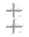
- FIGS. 3A-3Bshow another embodiment of a delivery device 300 , with reference to a method of use.
- the delivery device 300includes a handle 302 with a handle body 304 and an elongate tubular sheath 306 fixedly attached to and extending distally from a sheath-attached puller 338 that extends slidably through the handle body 304 .
- An elongate pusher/holder member 308extends slidably through a longitudinal lumen 307 of the sheath 306 , but is fixed relative to the handle body 304 .
- the handle body 304is shown in FIG. 3A in a side view revealing internal components of the handle 302 .
- FIG. 3Bshows a top view of the device 300 of FIG. 3A , with the sheath-attached puller 338 having been retracted proximally to actuate the device and release a distal portion of the stent 345 .
- the interior of the handle 302includes an advancement plate member (also functioning as a retaining member) 312 that is biased toward the distal end of the stent-holder member 308 .
- the retaining member 312is shown as being biased distally by a coil spring 315 , but other biasing means known in the art may be used.
- the retaining member 312is longitudinally freely movable along/relative to the holder member 308 and to the sheath-attached puller 309 .
- a deployment/advancement trigger member 316is pivotably mounted to the handle body 304 and the portion 316 a of it inside the handle body 304 is contacted by the retaining member 312 .
- That body-internal trigger portion 316 amoves freely relative to the inner holder member 308 and is configured to engage the sheath-attached puller 309 only during a proximal stroke, but to reciprocate freely back to the more distal position shown in FIG. 3A when released and moved back to that position by the bias of the spring 315 .
- the retaining member 312may engage the sheath-attached pulling member only when being moved proximally to pull it back upon actuation of the trigger 316 , then freely reciprocate distally back along it to the position shown in FIG. 3A .
- the advancement/retainer member 312includes two apertures (not shown) through which the puller 309 passes.
- a keeper member 322(which serves also to accommodate and prevent any backlash introduced by stretching and/or compression of the holder member 308 ) is mounted within an upper portion of the handle body 304 and biased toward its distal end.
- the keeper member 322is shown as being biased by a distally/pushing-tensioned coil spring 325 , but other biasing means known in the art may be used.
- the pusher member 308extends through the keeper member 322 without being bound thereto.
- the keeper member 322is also in mechanical communication with the sheath-attached puller 309 , and—unless the keeper member 322 is rotated against its spring-bias—it contacts the sheath-attached puller 309 in a manner that prevents distal motion of the sheath-attached puller 309 .
- a distal portion of the pusher/holder member 308is attached to or otherwise in releasable contact with an expandable prosthesis such as, for example, a self-expanding stent 345 .
- the attachmentmay include one or more an abutment, attachment with wire(s) or the like, the stent being concentrically constricted around the member 308 , or any other means.
- the stent 345may be constrained by this attachment and/or by the sheath 306 .
- a variety of methods and constructionsare known and are being developed in the art for providing stent attachment and deployment from a central pusher member whether or not it is accompanied by an outer sheath.
- One or more stabilizer elements 318may be provided, attaching the sheath-attached puller member 309 slidably to the holder member 308 .
- the sheath 306(which coaxially surrounds a distal length of the holder 308 ) is longitudinally slidable relative to the holder 308 .
- FIG. 3Ashows the device 300 in an unactuated state, with the stent 345 being sheathed (and therefore not clearly visible in FIG. 3A ).
- Actuationis described with reference to the top view of FIG. 3B .
- a userwill pivot the lower portion of the deployment trigger 316 toward the downward extending portion of the handle body 304 . This action captures/engages the sheath-attached puller member 309 and pulls it proximally.
- One advantage of this embodimentis that such actuation can be completed with only one hand, which will provide clear advantages to treatment personnel using the device.
- the handleremains in a fixed position relative to the expandable member 345 and relative to the patient's body (i.e., only the sheath moves longitudinally during actuation).
- the keeper member 322is disposed at an angle wherein it allows freely sliding distal-ward passage of the sheath-attached puller member 309 therethrough.
- the deployment trigger 316is released, the distal bias of the retaining member 312 against the in-handle portion 316 a of the trigger 316 moves it back to the default position shown in FIG. 3A .
- the distal bias of the keeper member 322generally retains it in the default position shown in FIG. 3A without retracting the pusher member 308 .
- FIGS. 3A-3Bmay be manually/directly actuated by depressing both the trigger 316 and the keeper member 322 . (However, neither element may need to be actuated in practice to effect deployment.) Then, the proximal-end ring 337 of the sheath-attached puller member 309 can be pulled to retract the sheath and deploy the stent 345 .
- the central pusher/holder member 308may be constructed as a catheter including one or more lumens configured to allow passage of, for example, a wire guide, contrast fluid, or other useful tools or materials.
- the sheath 306 and pusher/holder member 308are dimensioned and are sufficiently flexible and elongate to introduce a prosthetic device such as a stent into a patient's alimentary canal.
- the trigger 316 and keeper 322can also be actuated in a manner allowing the sheath-attached puller member 309 to be advanced distally to re-sheath a partially-unsheathed stent 345 to allow for repositioning, if needed.
- Those of skill in the artwill also appreciate that the present configuration for use with a “pistol grip”/“power grip” may readily be modified within the scope of the present disclosure to implement with use of an “internal precision grip.”
Landscapes
- Health & Medical Sciences (AREA)
- Engineering & Computer Science (AREA)
- Biomedical Technology (AREA)
- Cardiology (AREA)
- Oral & Maxillofacial Surgery (AREA)
- Transplantation (AREA)
- Heart & Thoracic Surgery (AREA)
- Vascular Medicine (AREA)
- Life Sciences & Earth Sciences (AREA)
- Animal Behavior & Ethology (AREA)
- General Health & Medical Sciences (AREA)
- Public Health (AREA)
- Veterinary Medicine (AREA)
- Media Introduction/Drainage Providing Device (AREA)
Abstract
Description
Claims (12)
Priority Applications (1)
| Application Number | Priority Date | Filing Date | Title |
|---|---|---|---|
| US14/181,272US9308108B2 (en) | 2013-03-13 | 2014-02-14 | Controlled release and recapture stent-deployment device |
Applications Claiming Priority (3)
| Application Number | Priority Date | Filing Date | Title |
|---|---|---|---|
| US201361179373P | 2013-03-13 | 2013-03-13 | |
| US201361779373P | 2013-03-13 | 2013-03-13 | |
| US14/181,272US9308108B2 (en) | 2013-03-13 | 2014-02-14 | Controlled release and recapture stent-deployment device |
Publications (2)
| Publication Number | Publication Date |
|---|---|
| US20150230954A1 US20150230954A1 (en) | 2015-08-20 |
| US9308108B2true US9308108B2 (en) | 2016-04-12 |
Family
ID=53797061
Family Applications (1)
| Application Number | Title | Priority Date | Filing Date |
|---|---|---|---|
| US14/181,272Active2034-04-18US9308108B2 (en) | 2013-03-13 | 2014-02-14 | Controlled release and recapture stent-deployment device |
Country Status (1)
| Country | Link |
|---|---|
| US (1) | US9308108B2 (en) |
Cited By (8)
| Publication number | Priority date | Publication date | Assignee | Title |
|---|---|---|---|---|
| US10500080B2 (en)* | 2016-10-31 | 2019-12-10 | Cook Medical Technologies Llc | Suture esophageal stent introducer |
| US10702408B2 (en) | 2016-10-31 | 2020-07-07 | Cook Medical Technologies Llc | Suture esophageal stent introducer |
| US10765545B2 (en) | 2016-10-31 | 2020-09-08 | Cook Medical Technologies Llc | Suture esophageal stent introducer |
| US10849775B2 (en) | 2016-10-31 | 2020-12-01 | Cook Medical Technologies Llc | Suture esophageal stent introducer parallel handle |
| US11141299B2 (en) | 2016-10-31 | 2021-10-12 | Cook Medical Technologies Llc | Suture esophageal stent introducer |
| US11141298B2 (en) | 2016-10-31 | 2021-10-12 | Cook Medical Technologies Llc | Suture esophageal stent introducer |
| US11246727B2 (en) | 2016-10-31 | 2022-02-15 | Cook Medical Technologies Llc | Suture esophageal stent introducer |
| US11413175B2 (en) | 2016-10-31 | 2022-08-16 | Cook Medical Technologies Llc | Tube and suture stent introducer system |
Families Citing this family (5)
| Publication number | Priority date | Publication date | Assignee | Title |
|---|---|---|---|---|
| US9456914B2 (en)* | 2015-01-29 | 2016-10-04 | Intact Vascular, Inc. | Delivery device and method of delivery |
| US10441449B1 (en) | 2018-05-30 | 2019-10-15 | Vesper Medical, Inc. | Rotary handle stent delivery system and method |
| US10449073B1 (en) | 2018-09-18 | 2019-10-22 | Vesper Medical, Inc. | Rotary handle stent delivery system and method |
| WO2020102679A1 (en)* | 2018-11-15 | 2020-05-22 | Baleen Medical Llc | Methods, systems, and devices for embolic protection |
| US11219541B2 (en) | 2020-05-21 | 2022-01-11 | Vesper Medical, Inc. | Wheel lock for thumbwheel actuated device |
Citations (121)
| Publication number | Priority date | Publication date | Assignee | Title |
|---|---|---|---|---|
| US1724983A (en) | 1927-03-31 | 1929-08-20 | Carl W Weiss | Roller-clutch bearing |
| US3132549A (en) | 1961-08-29 | 1964-05-12 | Alvin W Lee | Hand wrench |
| US3888258A (en) | 1972-11-07 | 1975-06-10 | Taichiro Akiyama | Drain for the eardrum and apparatus for introducing the same |
| US3897786A (en) | 1971-02-05 | 1975-08-05 | Richards Mfg Co | Disposable myringotomy apparatus |
| US4559041A (en) | 1984-06-25 | 1985-12-17 | Razi M Dean | Cannula introducers |
| US4655771A (en) | 1982-04-30 | 1987-04-07 | Shepherd Patents S.A. | Prosthesis comprising an expansible or contractile tubular body |
| US4921484A (en) | 1988-07-25 | 1990-05-01 | Cordis Corporation | Mesh balloon catheter device |
| US5026377A (en) | 1989-07-13 | 1991-06-25 | American Medical Systems, Inc. | Stent placement instrument and method |
| EP0566807A1 (en) | 1991-01-03 | 1993-10-27 | Jean-Claude Sgro | Self expanding vascular endoprosthesis and its implantation device |
| US5275151A (en) | 1991-12-11 | 1994-01-04 | Clarus Medical Systems, Inc. | Handle for deflectable catheter |
| US5372600A (en) | 1991-10-31 | 1994-12-13 | Instent Inc. | Stent delivery systems |
| US5415664A (en) | 1994-03-30 | 1995-05-16 | Corvita Corporation | Method and apparatus for introducing a stent or a stent-graft |
| US5433723A (en) | 1991-10-11 | 1995-07-18 | Angiomed Ag | Apparatus for widening a stenosis |
| US5443477A (en) | 1994-02-10 | 1995-08-22 | Stentco, Inc. | Apparatus and method for deployment of radially expandable stents by a mechanical linkage |
| US5458615A (en) | 1993-07-06 | 1995-10-17 | Advanced Cardiovascular Systems, Inc. | Stent delivery system |
| US5554894A (en) | 1994-10-28 | 1996-09-10 | Iolab Corporation | Electronic footswitch for ophthalmic surgery |
| EP0747021A2 (en) | 1995-06-07 | 1996-12-11 | Cook Incorporated | Stent introducer |
| US5681323A (en) | 1996-07-15 | 1997-10-28 | Arick; Daniel S. | Emergency cricothyrotomy tube insertion |
| US5683451A (en) | 1994-06-08 | 1997-11-04 | Cardiovascular Concepts, Inc. | Apparatus and methods for deployment release of intraluminal prostheses |
| US5690644A (en) | 1992-12-30 | 1997-11-25 | Schneider (Usa) Inc. | Apparatus for deploying body implantable stent |
| US5700269A (en) | 1995-06-06 | 1997-12-23 | Corvita Corporation | Endoluminal prosthesis deployment device for use with prostheses of variable length and having retraction ability |
| US5702418A (en) | 1995-09-12 | 1997-12-30 | Boston Scientific Corporation | Stent delivery system |
| US5709703A (en) | 1995-11-14 | 1998-01-20 | Schneider (Europe) A.G. | Stent delivery device and method for manufacturing same |
| US5733325A (en) | 1993-11-04 | 1998-03-31 | C. R. Bard, Inc. | Non-migrating vascular prosthesis and minimally invasive placement system |
| US5759186A (en) | 1991-06-14 | 1998-06-02 | Ams Medinvent S.A. | Transluminal Implantation device |
| US5776142A (en) | 1996-12-19 | 1998-07-07 | Medtronic, Inc. | Controllable stent delivery system and method |
| US5833694A (en) | 1995-05-25 | 1998-11-10 | Medtronic, Inc. | Stent assembly and method of use |
| WO1998053761A1 (en) | 1997-05-26 | 1998-12-03 | William A. Cook Australia Pty. Ltd. | A prosthesis and a method and means of deploying a prosthesis |
| US5906619A (en) | 1997-07-24 | 1999-05-25 | Medtronic, Inc. | Disposable delivery device for endoluminal prostheses |
| US5944727A (en) | 1998-09-02 | 1999-08-31 | Datascope Investment Corp. | Stent/graft catheter handle |
| US5968052A (en) | 1996-11-27 | 1999-10-19 | Scimed Life Systems Inc. | Pull back stent delivery system with pistol grip retraction handle |
| US5993460A (en) | 1998-03-27 | 1999-11-30 | Advanced Cardiovascular Systems, Inc. | Rapid exchange delivery system for stenting a body lumen |
| US6093194A (en) | 1998-09-14 | 2000-07-25 | Endocare, Inc. | Insertion device for stents and methods for use |
| US6146415A (en) | 1999-05-07 | 2000-11-14 | Advanced Cardiovascular Systems, Inc. | Stent delivery system |
| US6162231A (en) | 1998-09-14 | 2000-12-19 | Endocare, Inc. | Stent insertion device |
| US6168610B1 (en) | 1994-02-10 | 2001-01-02 | Endovascular Systems, Inc. | Method for endoluminally excluding an aortic aneurysm |
| US6254628B1 (en) | 1996-12-09 | 2001-07-03 | Micro Therapeutics, Inc. | Intracranial stent |
| US20020007206A1 (en) | 2000-07-06 | 2002-01-17 | Bui Dennis M. | Stent delivery system |
| WO2002005885A2 (en) | 2000-07-14 | 2002-01-24 | Cook Incorporated | Medical device with braid and coil |
| US6346118B1 (en) | 1983-12-09 | 2002-02-12 | Endovascular Technologies, Inc. | Thoracic graft and delivery catheter |
| US6375676B1 (en) | 1999-05-17 | 2002-04-23 | Advanced Cardiovascular Systems, Inc. | Self-expanding stent with enhanced delivery precision and stent delivery system |
| US6383211B1 (en) | 1998-07-10 | 2002-05-07 | American Medical Systems, Inc. | Stent placement instrument and method of assembly |
| US6391050B1 (en) | 2000-02-29 | 2002-05-21 | Scimed Life Systems, Inc. | Self-expanding stent delivery system |
| US6402760B1 (en) | 1999-08-24 | 2002-06-11 | Novatech Sa | Device for causing the release of an object, particularly a prosthesis, into a human or animal passage, and implantation system comprising a catheter and such a device |
| US6413269B1 (en) | 2000-07-06 | 2002-07-02 | Endocare, Inc. | Stent delivery system |
| US20020095203A1 (en) | 2001-01-18 | 2002-07-18 | Intra Therapeutics, Inc. | Catheter system with spacer member |
| US6428566B1 (en) | 2000-10-31 | 2002-08-06 | Advanced Cardiovascular Systems, Inc. | Flexible hoop and link sheath for a stent delivery system |
| US20020111666A1 (en) | 2001-02-15 | 2002-08-15 | Scimed Life Systems, Inc. | Stent delivery catheter positioning device |
| US20020183827A1 (en) | 2001-06-01 | 2002-12-05 | American Medical Systems | Stent delivery device and method |
| US6514261B1 (en) | 1998-09-30 | 2003-02-04 | Impra, Inc. | Delivery mechanism for implantable stent |
| US6520983B1 (en) | 1998-03-31 | 2003-02-18 | Scimed Life Systems, Inc. | Stent delivery system |
| US6530949B2 (en) | 1997-03-07 | 2003-03-11 | Board Of Regents, The University Of Texas System | Hoop stent |
| US20030093084A1 (en) | 2001-11-13 | 2003-05-15 | Optonol Ltd. | Delivery devices for flow regulating implants |
| US6592549B2 (en) | 2001-03-14 | 2003-07-15 | Scimed Life Systems, Inc. | Rapid exchange stent delivery system and associated components |
| US6599296B1 (en) | 2001-07-27 | 2003-07-29 | Advanced Cardiovascular Systems, Inc. | Ratcheting handle for intraluminal catheter systems |
| US20030191516A1 (en) | 2002-04-04 | 2003-10-09 | James Weldon | Delivery system and method for deployment of foreshortening endoluminal devices |
| US20030225445A1 (en) | 2002-05-14 | 2003-12-04 | Derus Patricia M. | Surgical stent delivery devices and methods |
| US6673101B1 (en) | 2002-10-09 | 2004-01-06 | Endovascular Technologies, Inc. | Apparatus and method for deploying self-expanding stents |
| US20040006380A1 (en) | 2002-07-05 | 2004-01-08 | Buck Jerrick C. | Stent delivery system |
| US20040010265A1 (en) | 2002-05-31 | 2004-01-15 | Wilson-Cook Medical, Inc. | Stent introducer apparatus |
| US6695875B2 (en) | 2000-03-14 | 2004-02-24 | Cook Incorporated | Endovascular stent graft |
| US20040093057A1 (en) | 2001-11-28 | 2004-05-13 | Aptus Endosystems, Inc. | Intraluminal prosthesis attachment systems and methods |
| US6749627B2 (en) | 2001-01-18 | 2004-06-15 | Ev3 Peripheral, Inc. | Grip for stent delivery system |
| US6755854B2 (en) | 2001-07-31 | 2004-06-29 | Advanced Cardiovascular Systems, Inc. | Control device and mechanism for deploying a self-expanding medical device |
| US6786918B1 (en) | 2000-10-17 | 2004-09-07 | Medtronic Vascular, Inc. | Stent delivery system |
| US20040181239A1 (en) | 2001-04-30 | 2004-09-16 | Jurgen Dorn | Self-expanding stent delivery device |
| US20040186547A1 (en) | 2001-06-19 | 2004-09-23 | Jurgen Dorn | Luer connector portion, and stent delivery system including a connector portion |
| US20040193180A1 (en) | 2001-10-12 | 2004-09-30 | Jon Buzzard | Method for locking handle deployment mechanism with medical device |
| US6808529B2 (en) | 2000-02-11 | 2004-10-26 | Edwards Lifesciences Corporation | Apparatus and methods for delivery of intraluminal prostheses |
| US20040215229A1 (en) | 2003-04-22 | 2004-10-28 | Medtronic Ave, Inc. | Stent delivery system and method |
| US20040220653A1 (en) | 2003-05-01 | 2004-11-04 | Borg Ulf R. | Bifurcated medical appliance delivery apparatus and method |
| US6821291B2 (en) | 2001-06-01 | 2004-11-23 | Ams Research Corporation | Retrievable stent and method of use thereof |
| US20040267282A1 (en) | 2003-06-30 | 2004-12-30 | Shkarubo Alexei Nikolaevich | Device for mounting medical instruments |
| US20050021123A1 (en) | 2001-04-30 | 2005-01-27 | Jurgen Dorn | Variable speed self-expanding stent delivery system and luer locking connector |
| US20050033402A1 (en) | 2003-01-17 | 2005-02-10 | Cully Edward H. | Deployment system for an expandable device |
| US20050033403A1 (en) | 2003-08-01 | 2005-02-10 | Vance Products, Inc. D/B/A Cook Urological Incorporated | Implant delivery device |
| US20050060018A1 (en) | 2003-09-16 | 2005-03-17 | Cook Incorporated | Prosthesis deployment system |
| US20050060016A1 (en) | 2003-09-12 | 2005-03-17 | Wu Patrick P. | Delivery system for medical devices |
| US20050080476A1 (en) | 2003-10-09 | 2005-04-14 | Gunderson Richard C. | Medical device delivery system |
| US20050085890A1 (en) | 2003-10-15 | 2005-04-21 | Cook Incorporated | Prosthesis deployment system retention device |
| EP1525859A2 (en) | 2003-10-23 | 2005-04-27 | Cordis Neurovascular, Inc. | Self-expanding stent and stent delivery system for treatment of vascular disease |
| US20050090890A1 (en) | 2003-09-12 | 2005-04-28 | Wu Patrick P. | Delivery system for medical devices |
| US20050090834A1 (en) | 2003-10-23 | 2005-04-28 | Aptus Endosystems, Inc. | Prosthesis delivery systems and methods |
| US20050107862A1 (en) | 2003-10-10 | 2005-05-19 | William Cook Europe Aps | Stent graft retention system |
| US20050113902A1 (en) | 2003-11-20 | 2005-05-26 | Geiser Timothy A. | Rapid-exchange delivery systems for self-expanding stents |
| US20050131514A1 (en) | 1999-05-20 | 2005-06-16 | Hijlkema Lukas J. | Delivery system for endoluminal implant |
| US6911039B2 (en) | 2002-04-23 | 2005-06-28 | Medtronic Vascular, Inc. | Integrated mechanical handle with quick slide mechanism |
| US20050149159A1 (en) | 2003-12-23 | 2005-07-07 | Xtent, Inc., A Delaware Corporation | Devices and methods for controlling and indicating the length of an interventional element |
| US20050177246A1 (en) | 1999-12-22 | 2005-08-11 | Arindam Datta | Biodegradable stent |
| US20050182475A1 (en) | 2003-09-02 | 2005-08-18 | Jimmy Jen | Delivery system for a medical device |
| US6939352B2 (en) | 2001-10-12 | 2005-09-06 | Cordis Corporation | Handle deployment mechanism for medical device and method |
| US6942688B2 (en) | 2000-02-29 | 2005-09-13 | Cordis Corporation | Stent delivery system having delivery catheter member with a clear transition zone |
| US20050209685A1 (en) | 2004-03-17 | 2005-09-22 | Shifrin Edward G | Graft delivery and anchoring system |
| US20050209670A1 (en) | 2004-03-02 | 2005-09-22 | Cardiomind, Inc. | Stent delivery system with diameter adaptive restraint |
| US20050240254A1 (en) | 2004-04-27 | 2005-10-27 | Michael Austin | Stent delivery system |
| US20050256562A1 (en) | 2004-05-14 | 2005-11-17 | Boston Scientific Scimed, Inc. | Stent delivery handle and assembly formed therewith |
| US20050273151A1 (en) | 2004-06-04 | 2005-12-08 | John Fulkerson | Stent delivery system |
| US20050288764A1 (en) | 2004-06-28 | 2005-12-29 | Xtent, Inc. | Devices and methods for controlling expandable prosthesis during develoyment |
| US20060004433A1 (en) | 2004-06-16 | 2006-01-05 | Cook Incorporated | Thoracic deployment device and stent graft |
| US20060009858A1 (en) | 2004-07-09 | 2006-01-12 | Gi Dynamics, Inc. | Methods and devices for placing a gastrointestinal sleeve |
| US6991646B2 (en) | 2001-12-18 | 2006-01-31 | Linvatec Biomaterials, Inc. | Method and apparatus for delivering a stent into a body lumen |
| US20060184226A1 (en) | 2005-02-16 | 2006-08-17 | Michael Austin | Delivery system for self-expanding stent, a method of using the delivery system, and a method of producing the delivery system |
| US20060184224A1 (en) | 2002-09-30 | 2006-08-17 | Board Of Regents, The University Of Texas System | Stent delivery system and method of use |
| US7122058B2 (en) | 2002-12-02 | 2006-10-17 | Gi Dynamics, Inc. | Anti-obesity devices |
| WO2007005799A1 (en) | 2005-06-30 | 2007-01-11 | Abbott Laboratories | Delivery system for a medical device |
| WO2007022395A1 (en) | 2005-08-17 | 2007-02-22 | C.R. Bard, Inc. | Variable speed stent delivery system |
| US20070060996A1 (en) | 2005-09-09 | 2007-03-15 | Richard Goodin | Coil shaft |
| US20070219614A1 (en) | 2003-10-14 | 2007-09-20 | William A. Cook Australia Pty Ltd. | Introducer for a side branch device |
| WO2008042266A2 (en) | 2006-09-28 | 2008-04-10 | Cook Incorporated | Thoracic aortic aneurysm repair apparatus and method |
| US20080300613A1 (en) | 2007-06-04 | 2008-12-04 | Shelton Iv Frederick E | Surgical instrument having a multiple rate directional switching mechanism |
| WO2009012061A1 (en) | 2007-07-16 | 2009-01-22 | Wilson-Cook Medical Inc. | Delivery device |
| US20090030497A1 (en) | 2007-07-25 | 2009-01-29 | Metcalf Justin M | Retention Wire For Self-Expanding Stent |
| US20090099640A1 (en) | 2006-03-30 | 2009-04-16 | Ning Weng | Axial Pullwire Tension Mechanism for Self-Expanding Stent |
| CA2739275A1 (en) | 2008-10-01 | 2010-04-08 | Impala, Inc. | Delivery system for vascular implant |
| US20100168834A1 (en) | 2008-12-30 | 2010-07-01 | Wilson-Cook Medical Inc. | Delivery Device |
| US20100262157A1 (en) | 2009-04-14 | 2010-10-14 | Medtronic Vascular, Inc. | Methods and Systems for Loading a Stent |
| US20110190865A1 (en) | 2010-01-29 | 2011-08-04 | Cook Medical Technologies Llc | Mechanically Expandable Delivery and Dilation Systems |
| US20120172963A1 (en) | 2007-07-16 | 2012-07-05 | Michael Ryan | Delivery device |
| WO2012099731A1 (en) | 2011-01-19 | 2012-07-26 | Cook Medical Technologies Llc | Rotary and linear handle mechanism for constrained stent delivery system |
| US20120221093A1 (en) | 2011-02-28 | 2012-08-30 | Mchugo Vincent | Short throw centered handle for stent delivery system |
| US8932342B2 (en)* | 2010-07-30 | 2015-01-13 | Cook Medical Technologies Llc | Controlled release and recapture prosthetic deployment device |
- 2014
- 2014-02-14USUS14/181,272patent/US9308108B2/enactiveActive
Patent Citations (149)
| Publication number | Priority date | Publication date | Assignee | Title |
|---|---|---|---|---|
| US1724983A (en) | 1927-03-31 | 1929-08-20 | Carl W Weiss | Roller-clutch bearing |
| US3132549A (en) | 1961-08-29 | 1964-05-12 | Alvin W Lee | Hand wrench |
| US3897786A (en) | 1971-02-05 | 1975-08-05 | Richards Mfg Co | Disposable myringotomy apparatus |
| US3888258A (en) | 1972-11-07 | 1975-06-10 | Taichiro Akiyama | Drain for the eardrum and apparatus for introducing the same |
| US4655771A (en) | 1982-04-30 | 1987-04-07 | Shepherd Patents S.A. | Prosthesis comprising an expansible or contractile tubular body |
| US4655771B1 (en) | 1982-04-30 | 1996-09-10 | Medinvent Ams Sa | Prosthesis comprising an expansible or contractile tubular body |
| US6346118B1 (en) | 1983-12-09 | 2002-02-12 | Endovascular Technologies, Inc. | Thoracic graft and delivery catheter |
| US4559041A (en) | 1984-06-25 | 1985-12-17 | Razi M Dean | Cannula introducers |
| US4921484A (en) | 1988-07-25 | 1990-05-01 | Cordis Corporation | Mesh balloon catheter device |
| US5026377A (en) | 1989-07-13 | 1991-06-25 | American Medical Systems, Inc. | Stent placement instrument and method |
| EP0566807A1 (en) | 1991-01-03 | 1993-10-27 | Jean-Claude Sgro | Self expanding vascular endoprosthesis and its implantation device |
| US5759186A (en) | 1991-06-14 | 1998-06-02 | Ams Medinvent S.A. | Transluminal Implantation device |
| US5433723A (en) | 1991-10-11 | 1995-07-18 | Angiomed Ag | Apparatus for widening a stenosis |
| US5372600A (en) | 1991-10-31 | 1994-12-13 | Instent Inc. | Stent delivery systems |
| US5275151A (en) | 1991-12-11 | 1994-01-04 | Clarus Medical Systems, Inc. | Handle for deflectable catheter |
| US5707376A (en) | 1992-08-06 | 1998-01-13 | William Cook Europe A/S | Stent introducer and method of use |
| US6755855B2 (en) | 1992-12-30 | 2004-06-29 | Boston Scientific Scimed, Inc. | Apparatus for deploying body implantable stents |
| US5690644A (en) | 1992-12-30 | 1997-11-25 | Schneider (Usa) Inc. | Apparatus for deploying body implantable stent |
| US5458615A (en) | 1993-07-06 | 1995-10-17 | Advanced Cardiovascular Systems, Inc. | Stent delivery system |
| US5733325A (en) | 1993-11-04 | 1998-03-31 | C. R. Bard, Inc. | Non-migrating vascular prosthesis and minimally invasive placement system |
| US6168610B1 (en) | 1994-02-10 | 2001-01-02 | Endovascular Systems, Inc. | Method for endoluminally excluding an aortic aneurysm |
| US5443477A (en) | 1994-02-10 | 1995-08-22 | Stentco, Inc. | Apparatus and method for deployment of radially expandable stents by a mechanical linkage |
| US5415664A (en) | 1994-03-30 | 1995-05-16 | Corvita Corporation | Method and apparatus for introducing a stent or a stent-graft |
| US5683451A (en) | 1994-06-08 | 1997-11-04 | Cardiovascular Concepts, Inc. | Apparatus and methods for deployment release of intraluminal prostheses |
| US5554894A (en) | 1994-10-28 | 1996-09-10 | Iolab Corporation | Electronic footswitch for ophthalmic surgery |
| US5833694A (en) | 1995-05-25 | 1998-11-10 | Medtronic, Inc. | Stent assembly and method of use |
| US5700269A (en) | 1995-06-06 | 1997-12-23 | Corvita Corporation | Endoluminal prosthesis deployment device for use with prostheses of variable length and having retraction ability |
| EP0747021A2 (en) | 1995-06-07 | 1996-12-11 | Cook Incorporated | Stent introducer |
| US5702418A (en) | 1995-09-12 | 1997-12-30 | Boston Scientific Corporation | Stent delivery system |
| US5709703A (en) | 1995-11-14 | 1998-01-20 | Schneider (Europe) A.G. | Stent delivery device and method for manufacturing same |
| US5681323A (en) | 1996-07-15 | 1997-10-28 | Arick; Daniel S. | Emergency cricothyrotomy tube insertion |
| US5968052A (en) | 1996-11-27 | 1999-10-19 | Scimed Life Systems Inc. | Pull back stent delivery system with pistol grip retraction handle |
| US6238402B1 (en) | 1996-11-27 | 2001-05-29 | Boston Scientific Corporation | Pull back stent delivery system with pistol grip retraction handle |
| US6391051B2 (en) | 1996-11-27 | 2002-05-21 | Scimed Life Systems, Inc. | Pull back stent delivery system with pistol grip retraction handle |
| US6669719B2 (en) | 1996-12-09 | 2003-12-30 | Microtherapeutics, Inc. | Intracranial stent and method of use |
| US6254628B1 (en) | 1996-12-09 | 2001-07-03 | Micro Therapeutics, Inc. | Intracranial stent |
| US5776142A (en) | 1996-12-19 | 1998-07-07 | Medtronic, Inc. | Controllable stent delivery system and method |
| US6530949B2 (en) | 1997-03-07 | 2003-03-11 | Board Of Regents, The University Of Texas System | Hoop stent |
| WO1998053761A1 (en) | 1997-05-26 | 1998-12-03 | William A. Cook Australia Pty. Ltd. | A prosthesis and a method and means of deploying a prosthesis |
| US5906619A (en) | 1997-07-24 | 1999-05-25 | Medtronic, Inc. | Disposable delivery device for endoluminal prostheses |
| US5993460A (en) | 1998-03-27 | 1999-11-30 | Advanced Cardiovascular Systems, Inc. | Rapid exchange delivery system for stenting a body lumen |
| US6520983B1 (en) | 1998-03-31 | 2003-02-18 | Scimed Life Systems, Inc. | Stent delivery system |
| US6383211B1 (en) | 1998-07-10 | 2002-05-07 | American Medical Systems, Inc. | Stent placement instrument and method of assembly |
| US5944727A (en) | 1998-09-02 | 1999-08-31 | Datascope Investment Corp. | Stent/graft catheter handle |
| US6093194A (en) | 1998-09-14 | 2000-07-25 | Endocare, Inc. | Insertion device for stents and methods for use |
| US6162231A (en) | 1998-09-14 | 2000-12-19 | Endocare, Inc. | Stent insertion device |
| US20030144671A1 (en) | 1998-09-30 | 2003-07-31 | Brooks Christopher J. | Delivery mechanism for implantable stents-grafts |
| US6514261B1 (en) | 1998-09-30 | 2003-02-04 | Impra, Inc. | Delivery mechanism for implantable stent |
| US6146415A (en) | 1999-05-07 | 2000-11-14 | Advanced Cardiovascular Systems, Inc. | Stent delivery system |
| US6860898B2 (en) | 1999-05-17 | 2005-03-01 | Advanced Cardiovascular Systems, Inc. | Self-expanding stent with enhanced delivery precision and stent delivery system |
| US6695862B2 (en) | 1999-05-17 | 2004-02-24 | Advanced Cardiovascular Systems, Inc. | Self-expanding stent with enhanced delivery precision and stent delivery system |
| US6893458B2 (en) | 1999-05-17 | 2005-05-17 | Advanced Cardiovascular Systems, Inc. | Self-expanding stent with enhanced delivery precision and stent delivery system |
| US6375676B1 (en) | 1999-05-17 | 2002-04-23 | Advanced Cardiovascular Systems, Inc. | Self-expanding stent with enhanced delivery precision and stent delivery system |
| US20050131514A1 (en) | 1999-05-20 | 2005-06-16 | Hijlkema Lukas J. | Delivery system for endoluminal implant |
| US6402760B1 (en) | 1999-08-24 | 2002-06-11 | Novatech Sa | Device for causing the release of an object, particularly a prosthesis, into a human or animal passage, and implantation system comprising a catheter and such a device |
| US20050177246A1 (en) | 1999-12-22 | 2005-08-11 | Arindam Datta | Biodegradable stent |
| US6808529B2 (en) | 2000-02-11 | 2004-10-26 | Edwards Lifesciences Corporation | Apparatus and methods for delivery of intraluminal prostheses |
| US6391050B1 (en) | 2000-02-29 | 2002-05-21 | Scimed Life Systems, Inc. | Self-expanding stent delivery system |
| US6942688B2 (en) | 2000-02-29 | 2005-09-13 | Cordis Corporation | Stent delivery system having delivery catheter member with a clear transition zone |
| US6695875B2 (en) | 2000-03-14 | 2004-02-24 | Cook Incorporated | Endovascular stent graft |
| US6629981B2 (en) | 2000-07-06 | 2003-10-07 | Endocare, Inc. | Stent delivery system |
| US20020007206A1 (en) | 2000-07-06 | 2002-01-17 | Bui Dennis M. | Stent delivery system |
| US6413269B1 (en) | 2000-07-06 | 2002-07-02 | Endocare, Inc. | Stent delivery system |
| WO2002005885A2 (en) | 2000-07-14 | 2002-01-24 | Cook Incorporated | Medical device with braid and coil |
| US6786918B1 (en) | 2000-10-17 | 2004-09-07 | Medtronic Vascular, Inc. | Stent delivery system |
| US6428566B1 (en) | 2000-10-31 | 2002-08-06 | Advanced Cardiovascular Systems, Inc. | Flexible hoop and link sheath for a stent delivery system |
| US6749627B2 (en) | 2001-01-18 | 2004-06-15 | Ev3 Peripheral, Inc. | Grip for stent delivery system |
| US20020095203A1 (en) | 2001-01-18 | 2002-07-18 | Intra Therapeutics, Inc. | Catheter system with spacer member |
| US20020111666A1 (en) | 2001-02-15 | 2002-08-15 | Scimed Life Systems, Inc. | Stent delivery catheter positioning device |
| US6890317B2 (en) | 2001-03-14 | 2005-05-10 | Scimed Life Systems, Inc. | Rapid exchange stent delivery system and associated components |
| US6592549B2 (en) | 2001-03-14 | 2003-07-15 | Scimed Life Systems, Inc. | Rapid exchange stent delivery system and associated components |
| US20040181239A1 (en) | 2001-04-30 | 2004-09-16 | Jurgen Dorn | Self-expanding stent delivery device |
| US20050021123A1 (en) | 2001-04-30 | 2005-01-27 | Jurgen Dorn | Variable speed self-expanding stent delivery system and luer locking connector |
| US20020183827A1 (en) | 2001-06-01 | 2002-12-05 | American Medical Systems | Stent delivery device and method |
| US6926732B2 (en) | 2001-06-01 | 2005-08-09 | Ams Research Corporation | Stent delivery device and method |
| US6821291B2 (en) | 2001-06-01 | 2004-11-23 | Ams Research Corporation | Retrievable stent and method of use thereof |
| US20040186547A1 (en) | 2001-06-19 | 2004-09-23 | Jurgen Dorn | Luer connector portion, and stent delivery system including a connector portion |
| US6599296B1 (en) | 2001-07-27 | 2003-07-29 | Advanced Cardiovascular Systems, Inc. | Ratcheting handle for intraluminal catheter systems |
| US6755854B2 (en) | 2001-07-31 | 2004-06-29 | Advanced Cardiovascular Systems, Inc. | Control device and mechanism for deploying a self-expanding medical device |
| US20040193180A1 (en) | 2001-10-12 | 2004-09-30 | Jon Buzzard | Method for locking handle deployment mechanism with medical device |
| US6939352B2 (en) | 2001-10-12 | 2005-09-06 | Cordis Corporation | Handle deployment mechanism for medical device and method |
| US6866669B2 (en) | 2001-10-12 | 2005-03-15 | Cordis Corporation | Locking handle deployment mechanism for medical device and method |
| US20030093084A1 (en) | 2001-11-13 | 2003-05-15 | Optonol Ltd. | Delivery devices for flow regulating implants |
| US20040093057A1 (en) | 2001-11-28 | 2004-05-13 | Aptus Endosystems, Inc. | Intraluminal prosthesis attachment systems and methods |
| US6991646B2 (en) | 2001-12-18 | 2006-01-31 | Linvatec Biomaterials, Inc. | Method and apparatus for delivering a stent into a body lumen |
| US7052511B2 (en) | 2002-04-04 | 2006-05-30 | Scimed Life Systems, Inc. | Delivery system and method for deployment of foreshortening endoluminal devices |
| US20030191516A1 (en) | 2002-04-04 | 2003-10-09 | James Weldon | Delivery system and method for deployment of foreshortening endoluminal devices |
| US6911039B2 (en) | 2002-04-23 | 2005-06-28 | Medtronic Vascular, Inc. | Integrated mechanical handle with quick slide mechanism |
| US20030225445A1 (en) | 2002-05-14 | 2003-12-04 | Derus Patricia M. | Surgical stent delivery devices and methods |
| US20040010265A1 (en) | 2002-05-31 | 2004-01-15 | Wilson-Cook Medical, Inc. | Stent introducer apparatus |
| JP2005532100A (en) | 2002-07-05 | 2005-10-27 | エドワーズ ライフサイエンシーズ アクチェンゲゼルシャフト | Stent delivery system |
| US20040006380A1 (en) | 2002-07-05 | 2004-01-08 | Buck Jerrick C. | Stent delivery system |
| US20060184224A1 (en) | 2002-09-30 | 2006-08-17 | Board Of Regents, The University Of Texas System | Stent delivery system and method of use |
| US6673101B1 (en) | 2002-10-09 | 2004-01-06 | Endovascular Technologies, Inc. | Apparatus and method for deploying self-expanding stents |
| US7122058B2 (en) | 2002-12-02 | 2006-10-17 | Gi Dynamics, Inc. | Anti-obesity devices |
| US20050033402A1 (en) | 2003-01-17 | 2005-02-10 | Cully Edward H. | Deployment system for an expandable device |
| US20040215229A1 (en) | 2003-04-22 | 2004-10-28 | Medtronic Ave, Inc. | Stent delivery system and method |
| US20040220653A1 (en) | 2003-05-01 | 2004-11-04 | Borg Ulf R. | Bifurcated medical appliance delivery apparatus and method |
| US20040267282A1 (en) | 2003-06-30 | 2004-12-30 | Shkarubo Alexei Nikolaevich | Device for mounting medical instruments |
| US20050033403A1 (en) | 2003-08-01 | 2005-02-10 | Vance Products, Inc. D/B/A Cook Urological Incorporated | Implant delivery device |
| US20050182475A1 (en) | 2003-09-02 | 2005-08-18 | Jimmy Jen | Delivery system for a medical device |
| US20050060016A1 (en) | 2003-09-12 | 2005-03-17 | Wu Patrick P. | Delivery system for medical devices |
| US20050090890A1 (en) | 2003-09-12 | 2005-04-28 | Wu Patrick P. | Delivery system for medical devices |
| US20050060018A1 (en) | 2003-09-16 | 2005-03-17 | Cook Incorporated | Prosthesis deployment system |
| US20050080476A1 (en) | 2003-10-09 | 2005-04-14 | Gunderson Richard C. | Medical device delivery system |
| JP2007508069A (en) | 2003-10-10 | 2007-04-05 | ウィリアム・クック・ヨーロッパ・アンパルトセルスカブ | Stent graft retention system |
| US20050107862A1 (en) | 2003-10-10 | 2005-05-19 | William Cook Europe Aps | Stent graft retention system |
| US7335224B2 (en) | 2003-10-10 | 2008-02-26 | William Cook Europe Aps | Stent graft retention system |
| US20070219614A1 (en) | 2003-10-14 | 2007-09-20 | William A. Cook Australia Pty Ltd. | Introducer for a side branch device |
| US20050085890A1 (en) | 2003-10-15 | 2005-04-21 | Cook Incorporated | Prosthesis deployment system retention device |
| EP1525859A2 (en) | 2003-10-23 | 2005-04-27 | Cordis Neurovascular, Inc. | Self-expanding stent and stent delivery system for treatment of vascular disease |
| US20050090834A1 (en) | 2003-10-23 | 2005-04-28 | Aptus Endosystems, Inc. | Prosthesis delivery systems and methods |
| US20050113902A1 (en) | 2003-11-20 | 2005-05-26 | Geiser Timothy A. | Rapid-exchange delivery systems for self-expanding stents |
| US20050149159A1 (en) | 2003-12-23 | 2005-07-07 | Xtent, Inc., A Delaware Corporation | Devices and methods for controlling and indicating the length of an interventional element |
| US20050209670A1 (en) | 2004-03-02 | 2005-09-22 | Cardiomind, Inc. | Stent delivery system with diameter adaptive restraint |
| US20050209685A1 (en) | 2004-03-17 | 2005-09-22 | Shifrin Edward G | Graft delivery and anchoring system |
| WO2005107644A1 (en) | 2004-04-27 | 2005-11-17 | Boston Scientific Limited | Stent delivery system |
| US20050240254A1 (en) | 2004-04-27 | 2005-10-27 | Michael Austin | Stent delivery system |
| US20050256562A1 (en) | 2004-05-14 | 2005-11-17 | Boston Scientific Scimed, Inc. | Stent delivery handle and assembly formed therewith |
| US20050273151A1 (en) | 2004-06-04 | 2005-12-08 | John Fulkerson | Stent delivery system |
| US20060004433A1 (en) | 2004-06-16 | 2006-01-05 | Cook Incorporated | Thoracic deployment device and stent graft |
| US20050288764A1 (en) | 2004-06-28 | 2005-12-29 | Xtent, Inc. | Devices and methods for controlling expandable prosthesis during develoyment |
| US20050288766A1 (en) | 2004-06-28 | 2005-12-29 | Xtent, Inc. | Devices and methods for controlling expandable prostheses during deployment |
| US20050288763A1 (en) | 2004-06-28 | 2005-12-29 | Xtent, Inc. | Custom-length self-expanding stent delivery systems with stent bumpers |
| US20060009858A1 (en) | 2004-07-09 | 2006-01-12 | Gi Dynamics, Inc. | Methods and devices for placing a gastrointestinal sleeve |
| US20060184226A1 (en) | 2005-02-16 | 2006-08-17 | Michael Austin | Delivery system for self-expanding stent, a method of using the delivery system, and a method of producing the delivery system |
| WO2007005799A1 (en) | 2005-06-30 | 2007-01-11 | Abbott Laboratories | Delivery system for a medical device |
| WO2007022395A1 (en) | 2005-08-17 | 2007-02-22 | C.R. Bard, Inc. | Variable speed stent delivery system |
| US20070060999A1 (en) | 2005-08-17 | 2007-03-15 | Michael Randall | Variable speed stent delivery system |
| US20070060996A1 (en) | 2005-09-09 | 2007-03-15 | Richard Goodin | Coil shaft |
| US20090099640A1 (en) | 2006-03-30 | 2009-04-16 | Ning Weng | Axial Pullwire Tension Mechanism for Self-Expanding Stent |
| WO2008042266A2 (en) | 2006-09-28 | 2008-04-10 | Cook Incorporated | Thoracic aortic aneurysm repair apparatus and method |
| US20080300613A1 (en) | 2007-06-04 | 2008-12-04 | Shelton Iv Frederick E | Surgical instrument having a multiple rate directional switching mechanism |
| US20120172963A1 (en) | 2007-07-16 | 2012-07-05 | Michael Ryan | Delivery device |
| WO2009012061A1 (en) | 2007-07-16 | 2009-01-22 | Wilson-Cook Medical Inc. | Delivery device |
| US20090024133A1 (en) | 2007-07-16 | 2009-01-22 | Fionan Keady | Delivery device |
| US20090030497A1 (en) | 2007-07-25 | 2009-01-29 | Metcalf Justin M | Retention Wire For Self-Expanding Stent |
| CA2739275A1 (en) | 2008-10-01 | 2010-04-08 | Impala, Inc. | Delivery system for vascular implant |
| WO2010040009A1 (en) | 2008-10-01 | 2010-04-08 | Cardiaq Valve Technologies, Inc. | Delivery system for vascular implant |
| US20100168834A1 (en) | 2008-12-30 | 2010-07-01 | Wilson-Cook Medical Inc. | Delivery Device |
| WO2010078352A1 (en) | 2008-12-30 | 2010-07-08 | Wilson-Cook Medical Inc. | Delivery device |
| US20100262157A1 (en) | 2009-04-14 | 2010-10-14 | Medtronic Vascular, Inc. | Methods and Systems for Loading a Stent |
| US20110190865A1 (en) | 2010-01-29 | 2011-08-04 | Cook Medical Technologies Llc | Mechanically Expandable Delivery and Dilation Systems |
| WO2011094527A1 (en) | 2010-01-29 | 2011-08-04 | Cook Medical Technologies Llc | Mechanically expandable delivery and dilation systems |
| US8932342B2 (en)* | 2010-07-30 | 2015-01-13 | Cook Medical Technologies Llc | Controlled release and recapture prosthetic deployment device |
| WO2012099731A1 (en) | 2011-01-19 | 2012-07-26 | Cook Medical Technologies Llc | Rotary and linear handle mechanism for constrained stent delivery system |
| WO2012099732A1 (en) | 2011-01-19 | 2012-07-26 | Cook Medical Technologies Llc | Delivery device |
| US20120221093A1 (en) | 2011-02-28 | 2012-08-30 | Mchugo Vincent | Short throw centered handle for stent delivery system |
| WO2012118638A1 (en) | 2011-02-28 | 2012-09-07 | Cook Medical Technologies Llc | Short throw centered handle for stent delivery system |
Non-Patent Citations (9)
| Title |
|---|
| Albee, F., "Bone Surgery with Machine Tools," Scientific American, Apr. 1936, pp. 178-181. |
| International Search Report and the Written Opinion No. for Intl. No. PCT/US2012/020597, date of mailing May 21, 2012, 13 pgs. |
| International Search Report and Written Opinion of the International Searching Authority for International Application No. PCT/US2008/069019, dated Oct. 17, 2008, 9 pages. |
| International Search Report and Written Opinion of the International Searching Authority for International Application No. PCT/US2009/069721, dated Feb. 19, 2010, 9 pages. |
| International Search Report and Written Opinion of the International Searching Authority for International Application No. PCT/US2011/022903, dated Mar. 24, 2011, 9 pages. |
| International Search Report and Written Opinion of the International Searching Authority for International Application No. PCT/US2012/025895, dated Jun. 6, 2012, 12 pages. |
| International Search Report for International Application No. PCT/US2012/020598, dated May 10, 2012, 4 pages. |
| Office action from co-pending U.S. Appl. No. 12/649,046, dated Apr. 5, 2013, 11 pages. |
| Office action from Japanese Application No. 2011-544591, dated Oct. 29, 2013, 5 pages. |
Cited By (8)
| Publication number | Priority date | Publication date | Assignee | Title |
|---|---|---|---|---|
| US10500080B2 (en)* | 2016-10-31 | 2019-12-10 | Cook Medical Technologies Llc | Suture esophageal stent introducer |
| US10702408B2 (en) | 2016-10-31 | 2020-07-07 | Cook Medical Technologies Llc | Suture esophageal stent introducer |
| US10765545B2 (en) | 2016-10-31 | 2020-09-08 | Cook Medical Technologies Llc | Suture esophageal stent introducer |
| US10849775B2 (en) | 2016-10-31 | 2020-12-01 | Cook Medical Technologies Llc | Suture esophageal stent introducer parallel handle |
| US11141299B2 (en) | 2016-10-31 | 2021-10-12 | Cook Medical Technologies Llc | Suture esophageal stent introducer |
| US11141298B2 (en) | 2016-10-31 | 2021-10-12 | Cook Medical Technologies Llc | Suture esophageal stent introducer |
| US11246727B2 (en) | 2016-10-31 | 2022-02-15 | Cook Medical Technologies Llc | Suture esophageal stent introducer |
| US11413175B2 (en) | 2016-10-31 | 2022-08-16 | Cook Medical Technologies Llc | Tube and suture stent introducer system |
Also Published As
| Publication number | Publication date |
|---|---|
| US20150230954A1 (en) | 2015-08-20 |
Similar Documents
| Publication | Publication Date | Title |
|---|---|---|
| US9308108B2 (en) | Controlled release and recapture stent-deployment device | |
| US8932342B2 (en) | Controlled release and recapture prosthetic deployment device | |
| AU2011293898B2 (en) | Staged deployment devices and methods for transcatheter heart valve delivery systems | |
| JP6625124B2 (en) | Inversion delivery device and method for prosthesis | |
| US9968358B2 (en) | Implant delivery system | |
| US8986363B2 (en) | Proximal release delivery system | |
| US20130035636A1 (en) | Delivery and Deployment Catheter for an Implantable Medical Device | |
| US8092468B2 (en) | Deployment handle for an implant deployment device | |
| US20180360633A1 (en) | Deployment handle for a pre-loaded iliac prosthesis delivery device | |
| WO2016123509A1 (en) | Reconstrainable stent delivery system with an annular lock and method | |
| IL170698A (en) | System for delivering a medical device to a body location | |
| WO2011017189A1 (en) | Roll sleeve mechanism for proximal release stent delivery device | |
| JP2008200498A (en) | Device for delivering a self-expanding stent into a body vessel | |
| CN105392452A (en) | Delivery device for partially unconstrained endoprosthesis | |
| JPH06197984A (en) | Device for implantation per cavity | |
| EP2777646B1 (en) | Controlled release and recapture stent-deployment device | |
| JP2017508575A (en) | Stent placement device | |
| CN118450867A (en) | Delivery systems and methods of use for endoluminal prostheses |
Legal Events
| Date | Code | Title | Description |
|---|---|---|---|
| AS | Assignment | Owner name:COOK IRELAND LIMITED, IRELAND Free format text:ASSIGNMENT OF ASSIGNORS INTEREST;ASSIGNOR:MCHUGO, VINCENT;REEL/FRAME:032232/0578 Effective date:20130426 Owner name:COOK MEDICAL TECHNOLOGIES LLC, INDIANA Free format text:ASSIGNMENT OF ASSIGNORS INTEREST;ASSIGNOR:COOK IRELAND LIMITED;REEL/FRAME:032232/0643 Effective date:20130501 | |
| STCF | Information on status: patent grant | Free format text:PATENTED CASE | |
| MAFP | Maintenance fee payment | Free format text:PAYMENT OF MAINTENANCE FEE, 4TH YEAR, LARGE ENTITY (ORIGINAL EVENT CODE: M1551); ENTITY STATUS OF PATENT OWNER: LARGE ENTITY Year of fee payment:4 | |
| MAFP | Maintenance fee payment | Free format text:PAYMENT OF MAINTENANCE FEE, 8TH YEAR, LARGE ENTITY (ORIGINAL EVENT CODE: M1552); ENTITY STATUS OF PATENT OWNER: LARGE ENTITY Year of fee payment:8 | |
| AS | Assignment | Owner name:WILMINGTON TRUST, NATIONAL ASSOCIATION, AS COLLATERAL AGENT, DELAWARE Free format text:SECURITY INTEREST;ASSIGNOR:COOK MEDICAL TECHNOLOGIES LLC;REEL/FRAME:066700/0277 Effective date:20240227 |