US9308047B2 - Rapid exchange bias laser catheter design - Google Patents
Rapid exchange bias laser catheter designDownload PDFInfo
- Publication number
- US9308047B2 US9308047B2US14/137,424US201314137424AUS9308047B2US 9308047 B2US9308047 B2US 9308047B2US 201314137424 AUS201314137424 AUS 201314137424AUS 9308047 B2US9308047 B2US 9308047B2
- Authority
- US
- United States
- Prior art keywords
- balloon
- catheter
- laser
- vessel
- lumen
- Prior art date
- Legal status (The legal status is an assumption and is not a legal conclusion. Google has not performed a legal analysis and makes no representation as to the accuracy of the status listed.)
- Active, expires
Links
- 238000000034methodMethods0.000claimsdescription35
- 239000000463materialSubstances0.000claimsdescription26
- 239000013307optical fiberSubstances0.000claimsdescription17
- 239000007788liquidSubstances0.000claimsdescription4
- 239000012530fluidSubstances0.000claimsdescription3
- 230000003213activating effectEffects0.000claims14
- 210000001367arteryAnatomy0.000description12
- 238000004891communicationMethods0.000description12
- 238000002679ablationMethods0.000description9
- 239000004033plasticSubstances0.000description8
- 229920003023plasticPolymers0.000description8
- 229910052751metalInorganic materials0.000description7
- 239000002184metalSubstances0.000description7
- 238000011282treatmentMethods0.000description7
- 238000002399angioplastyMethods0.000description6
- 239000003550markerSubstances0.000description6
- 230000008569processEffects0.000description6
- 238000005452bendingMethods0.000description5
- 239000000835fiberSubstances0.000description5
- -1as one example onlyInorganic materials0.000description3
- 210000004204blood vesselAnatomy0.000description3
- 208000037260Atherosclerotic PlaqueDiseases0.000description2
- 239000004677NylonSubstances0.000description2
- 239000004698PolyethyleneSubstances0.000description2
- 239000004809TeflonSubstances0.000description2
- 229920006362Teflon®Polymers0.000description2
- QVGXLLKOCUKJST-UHFFFAOYSA-Natomic oxygenChemical compound[O]QVGXLLKOCUKJST-UHFFFAOYSA-N0.000description2
- 230000008901benefitEffects0.000description2
- 239000008280bloodSubstances0.000description2
- 210000004369bloodAnatomy0.000description2
- 239000003814drugSubstances0.000description2
- 229940079593drugDrugs0.000description2
- 238000002651drug therapyMethods0.000description2
- 230000006870functionEffects0.000description2
- 238000013147laser angioplastyMethods0.000description2
- 230000003902lesionEffects0.000description2
- 230000007246mechanismEffects0.000description2
- 210000004165myocardiumAnatomy0.000description2
- 229910001000nickel titaniumInorganic materials0.000description2
- 229920001778nylonPolymers0.000description2
- 229910052760oxygenInorganic materials0.000description2
- 239000001301oxygenSubstances0.000description2
- 230000002093peripheral effectEffects0.000description2
- 229920000573polyethylenePolymers0.000description2
- 239000005060rubberSubstances0.000description2
- 229910001220stainless steelInorganic materials0.000description2
- 239000010935stainless steelSubstances0.000description2
- 200000000007Arterial diseaseDiseases0.000description1
- 208000031872Body RemainsDiseases0.000description1
- 0C[C@@]1(C(C*)C1)C=CNChemical compoundC[C@@]1(C(C*)C1)C=CN0.000description1
- 206010008479Chest PainDiseases0.000description1
- 229910000684Cobalt-chromeInorganic materials0.000description1
- FAPWRFPIFSIZLT-UHFFFAOYSA-MSodium chlorideChemical compound[Na+].[Cl-]FAPWRFPIFSIZLT-UHFFFAOYSA-M0.000description1
- WAIPAZQMEIHHTJ-UHFFFAOYSA-N[Cr].[Co]Chemical compound[Cr].[Co]WAIPAZQMEIHHTJ-UHFFFAOYSA-N0.000description1
- HZEWFHLRYVTOIW-UHFFFAOYSA-N[Ti].[Ni]Chemical compound[Ti].[Ni]HZEWFHLRYVTOIW-UHFFFAOYSA-N0.000description1
- 238000013459approachMethods0.000description1
- 230000003143atherosclerotic effectEffects0.000description1
- 239000002876beta blockerSubstances0.000description1
- 229940097320beta blocking agentDrugs0.000description1
- 230000005540biological transmissionEffects0.000description1
- 239000010952cobalt-chromeSubstances0.000description1
- 239000002872contrast mediaSubstances0.000description1
- 230000003247decreasing effectEffects0.000description1
- 239000013536elastomeric materialSubstances0.000description1
- 239000003527fibrinolytic agentSubstances0.000description1
- 239000003292glueSubstances0.000description1
- 238000013532laser treatmentMethods0.000description1
- 238000012986modificationMethods0.000description1
- 230000004048modificationEffects0.000description1
- 150000002823nitratesChemical class0.000description1
- 230000003287optical effectEffects0.000description1
- 229920000642polymerPolymers0.000description1
- 230000000750progressive effectEffects0.000description1
- 229910001285shape-memory alloyInorganic materials0.000description1
- 229910000679solderInorganic materials0.000description1
- 239000013077target materialSubstances0.000description1
- 210000001519tissueAnatomy0.000description1
- 230000000472traumatic effectEffects0.000description1
- 239000003071vasodilator agentSubstances0.000description1
Images


Classifications
- A—HUMAN NECESSITIES
- A61—MEDICAL OR VETERINARY SCIENCE; HYGIENE
- A61B—DIAGNOSIS; SURGERY; IDENTIFICATION
- A61B18/00—Surgical instruments, devices or methods for transferring non-mechanical forms of energy to or from the body
- A61B18/18—Surgical instruments, devices or methods for transferring non-mechanical forms of energy to or from the body by applying electromagnetic radiation, e.g. microwaves
- A61B18/20—Surgical instruments, devices or methods for transferring non-mechanical forms of energy to or from the body by applying electromagnetic radiation, e.g. microwaves using laser
- A61B18/22—Surgical instruments, devices or methods for transferring non-mechanical forms of energy to or from the body by applying electromagnetic radiation, e.g. microwaves using laser the beam being directed along or through a flexible conduit, e.g. an optical fibre; Couplings or hand-pieces therefor
- A61B18/24—Surgical instruments, devices or methods for transferring non-mechanical forms of energy to or from the body by applying electromagnetic radiation, e.g. microwaves using laser the beam being directed along or through a flexible conduit, e.g. an optical fibre; Couplings or hand-pieces therefor with a catheter
- A61B18/245—Surgical instruments, devices or methods for transferring non-mechanical forms of energy to or from the body by applying electromagnetic radiation, e.g. microwaves using laser the beam being directed along or through a flexible conduit, e.g. an optical fibre; Couplings or hand-pieces therefor with a catheter for removing obstructions in blood vessels or calculi
- A—HUMAN NECESSITIES
- A61—MEDICAL OR VETERINARY SCIENCE; HYGIENE
- A61B—DIAGNOSIS; SURGERY; IDENTIFICATION
- A61B18/00—Surgical instruments, devices or methods for transferring non-mechanical forms of energy to or from the body
- A61B18/18—Surgical instruments, devices or methods for transferring non-mechanical forms of energy to or from the body by applying electromagnetic radiation, e.g. microwaves
- A61B18/20—Surgical instruments, devices or methods for transferring non-mechanical forms of energy to or from the body by applying electromagnetic radiation, e.g. microwaves using laser
- A61B18/22—Surgical instruments, devices or methods for transferring non-mechanical forms of energy to or from the body by applying electromagnetic radiation, e.g. microwaves using laser the beam being directed along or through a flexible conduit, e.g. an optical fibre; Couplings or hand-pieces therefor
- A61B18/24—Surgical instruments, devices or methods for transferring non-mechanical forms of energy to or from the body by applying electromagnetic radiation, e.g. microwaves using laser the beam being directed along or through a flexible conduit, e.g. an optical fibre; Couplings or hand-pieces therefor with a catheter
- A—HUMAN NECESSITIES
- A61—MEDICAL OR VETERINARY SCIENCE; HYGIENE
- A61B—DIAGNOSIS; SURGERY; IDENTIFICATION
- A61B17/00—Surgical instruments, devices or methods
- A61B17/22—Implements for squeezing-off ulcers or the like on inner organs of the body; Implements for scraping-out cavities of body organs, e.g. bones; for invasive removal or destruction of calculus using mechanical vibrations; for removing obstructions in blood vessels, not otherwise provided for
- A61B2017/22038—Implements for squeezing-off ulcers or the like on inner organs of the body; Implements for scraping-out cavities of body organs, e.g. bones; for invasive removal or destruction of calculus using mechanical vibrations; for removing obstructions in blood vessels, not otherwise provided for with a guide wire
- A—HUMAN NECESSITIES
- A61—MEDICAL OR VETERINARY SCIENCE; HYGIENE
- A61B—DIAGNOSIS; SURGERY; IDENTIFICATION
- A61B17/00—Surgical instruments, devices or methods
- A61B17/22—Implements for squeezing-off ulcers or the like on inner organs of the body; Implements for scraping-out cavities of body organs, e.g. bones; for invasive removal or destruction of calculus using mechanical vibrations; for removing obstructions in blood vessels, not otherwise provided for
- A61B2017/22051—Implements for squeezing-off ulcers or the like on inner organs of the body; Implements for scraping-out cavities of body organs, e.g. bones; for invasive removal or destruction of calculus using mechanical vibrations; for removing obstructions in blood vessels, not otherwise provided for with an inflatable part, e.g. balloon, for positioning, blocking, or immobilisation
- A61B2017/22061—Implements for squeezing-off ulcers or the like on inner organs of the body; Implements for scraping-out cavities of body organs, e.g. bones; for invasive removal or destruction of calculus using mechanical vibrations; for removing obstructions in blood vessels, not otherwise provided for with an inflatable part, e.g. balloon, for positioning, blocking, or immobilisation for spreading elements apart
- A—HUMAN NECESSITIES
- A61—MEDICAL OR VETERINARY SCIENCE; HYGIENE
- A61B—DIAGNOSIS; SURGERY; IDENTIFICATION
- A61B18/00—Surgical instruments, devices or methods for transferring non-mechanical forms of energy to or from the body
- A61B18/18—Surgical instruments, devices or methods for transferring non-mechanical forms of energy to or from the body by applying electromagnetic radiation, e.g. microwaves
- A61B18/20—Surgical instruments, devices or methods for transferring non-mechanical forms of energy to or from the body by applying electromagnetic radiation, e.g. microwaves using laser
- A61B18/22—Surgical instruments, devices or methods for transferring non-mechanical forms of energy to or from the body by applying electromagnetic radiation, e.g. microwaves using laser the beam being directed along or through a flexible conduit, e.g. an optical fibre; Couplings or hand-pieces therefor
- A61B2018/2238—Surgical instruments, devices or methods for transferring non-mechanical forms of energy to or from the body by applying electromagnetic radiation, e.g. microwaves using laser the beam being directed along or through a flexible conduit, e.g. an optical fibre; Couplings or hand-pieces therefor with means for selectively laterally deflecting the tip of the fibre
Definitions
- the embodiments described hereinare generally directed to improved apparatus and methods for the delivery of laser energy, including without limitation, to a laser delivery catheter.
- Arteriesare the primary blood vessels that are responsible for providing blood and oxygen to the heart muscle. Arterial disease occurs when arteries become narrowed or blocked by a buildup of plaque (as some examples, atherosclerotic plaque or other deposits). When the blockage is severe, the flow of blood and oxygen to the heart muscle is reduced, causing chest pain. Arterial blockage by clots formed in a human body may be relieved in a number of traditional ways. Drug therapy, including nitrates, beta-blockers, and peripheral vasodilatator drugs to dilate the arteries or thrombolytic drugs to dissolve the clot, can be effective. If drug treatment fails, angioplasty may be used to reform or remove the atherosclerotic plaque or other deposits in the artery.
- Excimer laser angioplasty procedureis similar in some respects to conventional coronary balloon angioplasty.
- a narrow, flexible tube, the laser catheteris inserted into an artery in the arm or leg.
- the laser cathetercontains one or more optical fibers, which can transmit laser energy.
- the laser catheteris then advanced inside the artery to the targeted obstruction at the desired treatment site. After the laser catheter has been positioned, the laser is energized to “remove” the obstruction.
- the lesionis often engaged similar to conventional balloon angioplasty by crossing the blockage with a guidewire.
- the laser catheter's thin, flexible optical fibersfacilitate the desired positioning and alignment of the catheter.
- the clinicianuses the excimer laser, the clinician performs a controlled blockage removal by sending bursts of ultraviolet light through the catheter and against the blockage, a process called “ablation.”
- the catheteris then slowly advanced through the blockage reopening the artery. If there are multiple blockages, the catheter is advanced to the next blockage site and the above step is repeated. When the indicated blockages appear to be cleared, the catheter is withdrawn.
- the clinicianis able to ablate only material that is typically directly in front of the distal end of the catheter.
- the debulked tissue areais limited to an area approximately the size of the optical fiber area at the distal end of the catheter.
- follow-up balloon angioplastyis recommended.
- a cathetercomprising a catheter body, a light guide, a distal tip, a retaining wire and a balloon is provided according to one embodiment.
- the catheter bodyfor example may include a central axis, a first proximal end and a first distal end.
- the catheter bodymay also include a lumen disposed between the first proximal end and the first distal end, the lumen having an opening at the first distal end.
- the light guidemay include a second proximal end and a second distal end.
- the light guidemay also include at least one optical fiber and may at least partially be disposed within the lumen and movable therein.
- the distal tipmay be positioned at the periphery of the catheter body and extend from the first distal end of the catheter body.
- the distal tipmay also include a guidewire lumen that includes a guidewire port at the distal end of the distal tip.
- the retaining wiremay be coupled with the distal tip and slidably coupled with the light guide.
- the balloonfor example, may be positioned between the opening at the first distal end of the catheter body and the distal tip.
- the balloonmay be configured to bias the light guide away from the central axis from the catheter body when the balloon is inflated.
- the cathetermay include a guidewire lumen. In some embodiments, at least a portion of the guidewire lumen may be located within the distal tip and/or a portion may be located within the catheter body. In some embodiments, the guidewire lumen may be parallel with the lumen within the catheter body. In some embodiments, the catheter body may include a proximal guidewire port and/or a distal guidewire port. In some embodiments, the catheter may also include a balloon and/or a balloon lumen (or tube) coupled with the balloon. In some embodiments, the distal tip and/or the light guide may include a radiopaque marker
- a catheter having a first proximal end and a first distal endis provided according to another embodiment.
- the cathetermay include a light guide lumen having a second distal end and a second proximal end, the second proximal end being substantially contiguous with the first proximal end, the second distal end having an opening.
- a distal tipmay also be included having a third proximal end and a third distal end, the third proximal end being substantially contiguous with the second distal end.
- the cathetermay include a balloon lumen having a fourth distal end and fourth proximal end, the fourth proximal end being substantially contiguous with the second distal end.
- a balloonmay be coupled with the balloon lumen at the fourth distal end.
- a guidewire lumenmay be included that extends through the distal tip.
- the inventioncomprises a catheter having a catheter body including a central axis between a first proximal end and a first distal end.
- the housinghas a lumen disposed between the first proximal end and the first distal end in communication with a cavity disposed proximate the first distal end.
- a laser delivery memberis movable and at least partially disposed within the lumen having a second proximal end and a second distal end.
- a rampis disposed at an angle to the central axis and proximate the first distal end of the catheter body within the cavity.
- the rampis in communication with the lumen and is adapted to move the second distal end of the laser delivery member outwardly from the central axis of the elongated member.
- a guidewireis in mechanical communication with both the laser delivery member and the catheter body. The guidewire is adapted to bias the second distal end of the laser delivery member generally inwardly toward the central axis of the housing.
- the rampis used to determine the offset of the central axis of the tip of the laser delivery member from the central axis of the housing, while keeping the axes substantially parallel, by adjusting the extent to which the laser delivery member travels on the ramp, and the disposition of the laser delivery member on the guidewire maintains the offset tip substantially parallel to the central axis of the housing. Methods of using same are also disclosed.
- FIG. 1is perspective elevated view of a catheter according to one embodiment
- FIG. 2is an exploded perspective view of a cavity of FIG. 1 ;
- FIG. 3is an exploded perspective view of FIG. 1 showing one embodiment of a ramp
- FIG. 4is an exploded perspective view of FIG. 1 showing a ramp, a laser delivery member, and a guidewire;
- FIG. 5is a perspective elevated view of a first embodiment of a support structure
- FIG. 6is a top plan view of FIG. 5 ;
- FIG. 7is a side plan view of FIG. 5 ;
- FIG. 8is a top plan view of a second embodiment of a support structure
- FIG. 9is a side plan view of FIG. 8 ;
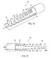
- FIG. 10is a perspective elevated view of a third embodiment of a support structure
- FIG. 11is a top plan view of FIG. 10 ;
- FIG. 12is a perspective elevated view of a fourth embodiment of a support structure
- FIG. 13is a perspective elevated view of a fifth embodiment of a support structure
- FIG. 14is a perspective elevated view of a sixth embodiment of a support structure
- FIG. 15is a top plan view of a seventh embodiment of a support structure.
- FIG. 16is a perspective elevated view of FIG. 15 .
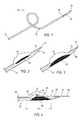
- FIG. 17is a side view of a balloon biasing catheter according to one embodiment.
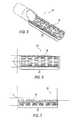
- FIG. 18Ashows a side view of the distal end of a deflated balloon biasing catheter according to one embodiment.
- FIG. 18Bshows a side view of the distal end of a inflated balloon biasing catheter according to one embodiment.
- FIG. 18Cshows a side view of the distal end of a deflated balloon biasing catheter with a proximal guidewire port within the catheter body according to one embodiment.
- FIG. 18Dshows a side view of the distal end of a deflated balloon biasing catheter with a proximal guidewire port proximal with the distal tip according to one embodiment.
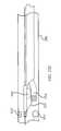
- FIG. 19shows an end view of the distal tip of a balloon biasing catheter according to one embodiment.
- FIG. 20is a cutaway view of the distal tip of a balloon biasing catheter according to one embodiment.
- FIG. 21is a cutaway view of balloon biasing catheter showing a light guide, balloon lumen and guidewire lumen according to one embodiment.
- FIGS. 22A, 22B, and 22Cshow a cutaway view of a balloon biasing catheter in use within a vessel according to one embodiment.
- FIG. 23is a flowchart describe one embodiment for using a balloon biasing catheter.
- FIG. 24is another flowchart describe one embodiment for using a balloon biasing catheter.
- FIG. 25shows a cutaway view of the distal tip of a balloon biasing catheter according to one embodiment.
- a catheter 10having an elongated housing 12 .
- the elongated housing 12includes a central axis between a first proximal end 14 and a first distal end 16 .
- a cavity 18is located proximate to the first distal end 16 of elongated housing 12 having a ramp 20 at an angle to the central axis of the housing 12 .
- the angle of the ramp 20may but need not be the same over the length of the ramp.
- the housingincludes a tapering end 30 and a guidewire aperture 32 capable of accepting the guidewire 28 .
- a laser delivery member 22comprising one or more optical fibers capable of transmitting light energy is disposed within a lumen 26 of the housing 12 having a second proximal end (not shown) and a second distal end 24 movable therein.
- the laser delivery member 22may be in mechanical communication with a guidewire 28 as further discussed below.
- the guidewire 28is threaded through a needle (not shown) into the artery and the needle is removed.
- the guidewireis advanced to or near the treatment site and may be inserted at its distal end into or across the lesion to be treated, as desired.
- the guidewire 28serves as a tracking guide for the housing 12 and laser delivery member 22 to run on.
- Guidewires for such usesare known in the art and may comprise those with diameters between about 0.010 and 0.06 inches, with 0.014 and 0.018 inches diameter being typical sizes for artery applications.
- the guidewiresmay have bendable tips of coiled wire or plastic and a more rigid shaft of tapered ground stainless steel or other suitable material for push and torque transmission.
- the housing 12 and laser delivery member 22are introduced coaxially, either sequentially or simultaneously, onto the guidewire 28 and advanced to a target area as further discussed below.
- the housing 12is introduced onto the guidewire 28 that has been inserted into the patient, and the housing is advanced to or near the treatment site such that portions of the guidewire 28 are disposed at least initially within the guidewire aperture 32 , tapering end 30 , and lumen 26 of the housing.
- the laser delivery member 22is then introduced onto the guidewire 28 so disposed within the catheter 10 .
- the laser delivery member 22is then advanced along the guidewire 28 such that the distal end 24 of the laser delivery member 22 becomes supported by the ramp 20 and oriented within the cavity 18 at any angle between 1 degree and 90 degrees in relation to the central axis of the housing 12 , as desired by the user.
- Laser energyis then applied to the treatment site according to methods and protocols known to those of ordinary skill in the art.
- the position of the laser delivery member 22may optionally be varied by the user by moving the member 22 proximally or distally in order to adjust the angle of disposition of its distal end 24 .
- the offset of the central axis of the tip of the laser delivery member 22 from the central axis of the housing 12may be varied by adjusting the distance that the delivery member 22 travels on the ramp 20 while keeping the central axis of the tip substantially parallel to the central axis of the housing 12 .
- the catheter 10 containing the laser delivery member 22may optionally be rotated along its central axis during the laser treatment and thereby apply laser energy to areas of the treatment site within the are of the rotation.
- the guidewire 28may be withdrawn before application of laser energy and after the laser delivery member 22 has been introduced via the guidewire 28 into the lumen 26 of the housing 12 .
- the elongated housing 12is an elongated structure having a lumen or lumen 26 large enough to accommodate the laser delivery member 22 and guidewire 28 .
- the lumen 26extends the entire length of the housing 12 from the first proximal end 14 to the first distal end 16 .
- the lumen 26may extend only to the ramp 20 .
- Various control mechanismsincluding electrical, optical, and mechanical control mechanisms may be employed with the housing 12 permitting the catheter to be specifically directed to a target area (not shown) within the blood vessel.
- One embodiment of the housingincludes a tapering end 30 and a guidewire aperture 32 capable of accepting the guidewire 28 .
- the housing 12may be made from any rigid, semi-flexible, or flexible material including a combination thereof made from a material including metal, plastic, rubber, and the like. Round or flat metal ribbon wire may be embedded within the material, inserted through the cavity 18 , or disposed at the first distal end 16 to add stability to the housing 12 at the first distal end 16 .
- the length of the housing 12may be varied as desired.
- the housing 12may be one piece or have a plurality of sections including a support structure section at the first distal end 16 as discussed further below.
- the distal end 16 of the housing 12may include a non-traumatic polymer tip separate or integrated into the housing 12 . This allows the forces seen in bending to be dissipated throughout the structure, reducing stress risers that could cause failure.
- the housing 12may also include at least one wire disposed within the lumen 26 to add robustness to the housing 12 .
- the lumen 26is in communication with cavity 18 and wire aperture 32 .
- the lumen 26is open to the exterior of
- the ramp 20is disposed within cavity 18 and is configured to project the laser delivery member 22 outwardly at various determinable angles.
- the ramp 20is used to determine the offset of the central axis of the tip of the laser delivery member 22 from the central axis of the housing 20 , while keeping the axes substantially parallel, by adjusting the extent to which the laser delivery member 22 travels on the ramp 20 .
- the disposition of the laser delivery member 22 on the guidewire 28maintains the offset tip substantially parallel to the central axis of the housing 12 .
- the angle of lateral deviation of the ramp 20 from central axis of the housing 12will vary in range as desired from one (1) degree to ninety (90) degrees, more usually in the range from thirty (30) degrees to sixty-five (65) degrees.
- ramp 20may be adjustable, as one example only, by inflation of a balloon, and/or the ramp 20 may be slidable to allow varying degrees of offset.
- the ramp 20may be a built-up feature within the lumen 26 of the housing 12 and may be located anywhere along the longitudinal length of the housing 12 , but preferably at or within about 3 cm from the first distal end 16 of the housing 12 .
- the ramp 20may be formed or fused to the internal wall of the housing 12 and made from metal, plastic, rubber, and the like.
- the ramp length (RL)is generally 1 cm. However, the ramp length (RL) may also be varied.
- the first distal end 16 of the housing 12may be formed from plastic, metal, or any combination thereof. When metal is used, materials must be selected to provide appropriate flexibility without producing failure since the cavity 18 tends to reduce the structural integrity of some portions of the housing 12 .
- the first distal end 16comprises a shape memory alloy, as one example only, nickel-titanium alloy.
- the first distal end 16may comprise a stent-like structure proximal, distal, within, or a combination of such proximate the cavity 18 .
- the stent-like structuremay be made from at least one of stainless steel, cobalt-chromium, nickel titanium, and the like.
- An alternative embodiment of the housing 12comprises having at least one section at the first distal end 16 .
- a first embodiment of a support structureis support member 34 as shown in FIGS. 5-7 .
- the support member 34may be used to support the first distal end 16 while providing flexibility without producing failure.
- the first distal end 16 of the housing 12may otherwise experience limited torsional and bending strength of the area around the cavity 18 specifically traversing bends having a radius of about 0.75 inches.
- the support member 34assists in withstanding the torsional and bending forces when traversing bends of about 0.75 inches, while maintaining aspects of both integrity and functionality.
- support member 34reinforces the area around the cavity 18 at the first distal end 16 with struts 36 forming a stent-like pattern 38 .
- Support member 34is formed from metal, plastic, or combinations thereof, and is at least partially axially disposed around the wall of the first distal end 16 of the housing 12 .
- the housing 12may be one longitudinal piece or have a plurality of sections including the support structure as described above disposed at the first distal end 16 of the housing 12 .
- Other embodiments of the support structureinclude a marker band proximate the first distal end 16 of the housing 12 and radiopaque markers at various intervals along the ramp 20 to demarcate acceptable ramp 20 positions for the catheter 10 .
- a usermay place a catheter at a first mark on the ramp to increase the offset for ablation to 1 mm.
- a second markmight equal a 1.5 mm offset. This way the support structure may be used progressively, as one example only, as a progressive atherectomy tool. Additional embodiments having generally similar benefits may also be used, as further discussed below.
- a second embodiment of a support structureis shown as second support member 40 having a spring-like geometry 42 .
- the support member 40may be used to support the first distal end 16 while providing flexibility without producing failure.
- the second support member 40acts as a backbone for the first distal end 16 of the housing 12 .
- the spring-like geometry 42permits flexing without causing failure.
- the height H of the spring-like geometry 42may be of any height but is preferably below the centerline of the second support member 40 .
- the ramp 20may be molded over the spring like geometry 42 including having a top coat (not shown).
- a third embodiment of a support structureis shown as a third support member 44 .
- the support member 44may be used to support the first distal end 16 while providing flexibility without producing failure.
- the third support member 44provides variable stiffness along the length of the member 44 .
- Member 44is the most rigid at rib 46 and most flexible at rib 48 . This flexibility is accomplished by having the ribs increase in width W and distance D in addition to decreasing the side of a beam 50 as shown in FIG. 11 .
- Beam 50tapers from a first wide beam width BW 1 to a narrower beam width BW 2 .
- a tip 52 having a tip length TL disposed at the distal end support member 44functions to provide support for the first distal end 16 of the housing 12 while allowing additional flexibility.
- the ramp 20may be molded over the spring-like geometry 42 including having a top coat (not shown).
- the support member length Lmay be varied depending on user requirements including varying the tip length TL.
- FIG. 12shows a fourth embodiment of a support structure as fourth support member 54 disposed at the first distal end 16 of the housing 12 .
- the support member 54may be used to support the first distal end 16 while providing flexibility without producing failure.
- Support member 54includes a rigid body 56 and a variably rigid base 58 extending from the body 56 .
- Body 56includes an aperture 57 in communication with lumen 26 .
- the base 58may be elastomeric having the greatest flexibility at distal end 60 .
- the ramp 20may be molded over the base 58 including having a top coat (not shown).
- the support member base length BLmay be varied according to user requirements.
- FIG. 13shows a fifth embodiment of a support structure as fifth support member 62 .
- the support member 62includes a rigid body 64 having a flexible tapered nose portion 66 .
- At least the nose portion 66may be comprised of elastomeric material, as one example only, Rebax 55D available from Arkema.
- the body 64is configured to communicate with the first distal end 16 of the housing 12 .
- An aperture 68is disposed within body 64 in communication with lumen 26 of the housing 12 and is configured to accommodate both the laser delivery member 22 and guidewire 28 .
- Aperture 68is also in communication with the nose widow 69 .
- the nose window 69 of the nose portion 66includes a nose ramp 70 configured to project the laser delivery member 22 outwardly at various predetermined angles.
- the ramp 20is used to determine the offset of the central axis of the tip of the laser delivery member 22 from the central axis of the housing 20 , while keeping the axes substantially parallel, by adjusting the extent to which the laser delivery member 22 travels on the ramp 20 .
- the disposition of the laser delivery member 22 on the guidewire 28maintains the offset tip substantially parallel to the central axis of the housing 12 .
- the angle of lateral deviation of the ramp 20 from the housing 12will vary in range as desired from one (1) degree to ninety (90) degrees, more usually in the range from thirty (30) degrees to sixty-five (65) degrees.
- the nose portionalso includes a nose lumen 72 and a nose guidewire aperture 74 .
- the guidewire 28 disposed within and in mechanical communication the laser delivery member 22extends outwardly from the second distal end 24 of the laser delivery member 22 and is guided through the nose lumen 72 and extending out the guidewire aperture 74 . Both the nose lumen 72 and guidewire aperture 74 provide securement for the guidewire 28 so that the guidewire 28 may properly bias the second distal end 24 of the laser delivery member 22 generally inwardly toward the central axis of the body 64 .
- FIG. 14shows a sixth embodiment of a support structure as sixth support member 80 .
- the support member 80may be used to support the first distal end 16 while providing flexibility without producing failure.
- Support member 80includes a rigid body 82 and at least two variably rigid legs 84 extending from the body 82 .
- Body 82includes an aperture 86 in communication with the lumen 26 .
- the body 82may be elastomeric having the greatest flexibility at distal end 88 .
- the legs 84may be of any shape extending from the body 82 .
- the ramp 20may be molded over the legs 84 including having a top coat (not shown).
- the support member leg length LLmay be varied depending on user requirements.
- FIGS. 15 and 16show a seventh embodiment of a support structure as seventh support member 90 .
- the support member 90may be used to support the first distal end 16 while providing flexibility without producing failure.
- the first distal end 16 of the housing 12may otherwise experience limited torsional and bending strength of the area around the cavity 18 specifically traversing bends having a radius of about 0.75 inches.
- the support member 90assists in withstanding the torsional and bending forces when traversing bends of about 0.75 inches while maintaining both integrity and functionality.
- Support member 90reinforces the area around the cavity 18 at the first distal end 16 with a braid 92 forming a stent-like pattern 94 .
- Support member 90is formed from metal or plastic and is at least partially axially disposed around the wall of the first distal end 16 of the housing 12 .
- the housing 12may be one longitudinal piece or have a plurality of sections including the support structure as described above disposed at the first distal end 16 of the housing 12 .
- Support member 90includes a rigid body 92 and a variably rigid base 94 forming the stent-like pattern 94 extending from the body 92 .
- Body 92includes an aperture 96 in communication with lumen 26 .
- the base 94may be elastomeric having the greatest flexibility at distal end 98 .
- a tip 100 having a tip length TL disposed at the distal end support member 90functions to provide support for the first distal end 16 of the housing 12 while allowing additional flexibility.
- the ramp 20may be molded over the base 94 including having a top coat (not shown).
- the support member stent-like length SLmay be varied depending on user requirements.
- the housing 12In operation, once the guidewire 28 is in place, or as it is being positioned, the housing 12 is inserted.
- This housing 12has a central lumen 26 , which may include the laser delivery member 22 and guidewire 28 .
- the housing 12 and the laser delivery member 22are advanced through the guidewire into the desired target area. Therefore, the guidewire 28 is in mechanical communication with both the laser delivery member 22 and the elongated housing 12 .
- the housing 12may be advanced prior to inserting the laser delivery member 22 . As the laser delivery member 22 approaches the ramp 20 , it is biased in an outwardly direction through the cavity 18 . The further the laser delivery member 22 is advanced, the more it projects outwardly from the cavity 18 at the first distal end 16 of the housing 12 .
- the guidewire 28 disposed within the laser delivery member 22biases the second distal end 24 of the laser delivery member 22 inwardly providing a travel path and forcing the second distal end 24 to face forward along the guidewire 28 and generally parallel to the centerline of the housing 12 . Otherwise, the second distal end 24 of the laser delivery member 22 would continue along the ramp 20 further projecting away from the centerline of the housing 12 and would not be “attacking” the target area in front of the catheter 10 as desired.
- FIG. 17is a side view of a balloon biasing catheter according to one embodiment.
- a balloon biasing cathetermay include a catheter body 1705 (or elongated housing) with a light guide 1710 disposed within a lumen of catheter body 1705 and extending from an aperture within catheter body 1705 .
- light guide 1710may include a plurality of fiber optics.
- the light guidemay be a liquid light guide and/or a combination of a liquid light guide and a fiber optic light guide.
- the light guideis free to slide within the lumen of the catheter body.
- the light guide lumenmay slide relative to the catheter body.
- the light guidemay be fixed within the lumen of the catheter body.
- Light guide 1710may be located within catheter body 1705 and may extend from the proximal end of the catheter body to the distal end of the catheter body. At the proximal end of the catheter body, light guide 1710 may be coupled with a laser coupler.
- the light guide lumenmay include an aperture at or near the distal end of catheter body 1705 from which light guide 1710 may extend. In some embodiments, light guide 1710 may extend 1-10 mm from the aperture. In some embodiments, light guide 1710 may also include a radiopaque marker band 1712 near the distal end.
- a balloon biasing cathetermay also include a guidewire lumen.
- the guidewire lumenmay be configured to allow a guidewire to pass and/or slide therethrough.
- the guidewire lumenmay extend, for example, from distal guidewire port 1720 through a portion of catheter body 1705 .
- the guidewire lumenmay extend to or near the proximal end of catheter body 1705 .
- guidewire lumenmay extend from the distal end to a position proximal with the light guide aperture and/or proximal with balloon 1810 .
- the guidewire lumenmay be configured to accept a guidewire and allow the guidewire to slide within the guidewire lumen 1812 .
- Proximal guidewire port 1720may be located any where along catheter body 1705 .
- FIG. 18Ashows a side view of the distal end of a balloon biasing catheter with a deflated (or partially deflated) balloon.
- Distal tip 1733extends beyond the catheter body.
- distal tip 1733may be integral with catheter body 1705 ; for example, distal tip 1733 may be manufactured as part of catheter body 1705 .
- distal tip 1733extends beyond the aperture of the light guide lumen.
- distal tip 1733may be contiguous and/or coterminal with a peripheral portion of the catheter body.
- Guidewire lumen 1812extends through distal tip 1733 and terminates at distal guidewire port 1720 .
- a balloon biasing cathetermay slide over a previously placed guidewire by introducing the proximal end of the guidewire through distal guidewire port 1720 , into guidewire lumen 1812 , and then sliding the balloon biasing catheter over the guidewire within guidewire lumen 1812 .
- the proximal end of the guidewiremay then exit the balloon biasing catheter through proximal guidewire port 1725 .
- Distal tip 1733may also include a radiopaque marker 1805 .
- Distal tip 1733may also include balloon 1810 .
- Balloon 1810may be located between distal tip 1733 and the distal end of light guide 1710 .
- distal tip 1733may include a shelf-like structure upon which balloon 1810 may be positioned.
- Balloon 1810may be coupled with a balloon lumen (or tube) 1813 .
- Balloon lumen 1813may extend to balloon port 1730 .
- Balloon 1810may be inflated and/or deflated by pressurizing balloon lumen 1813 with liquid using balloon port 1730 . By inflating balloon 1810 , light guide 1710 may be biased away from the central axis of catheter body 1705 as shown in FIG. 18B .
- light guide 1710remains relatively parallel with the central axis of catheter body 1705 and/or distal tip 1733 when balloon 1810 is inflated.
- retaining wire 1715aids in keeping light guide 1710 relatively parallel with catheter body 1705 .
- Balloon 1810may deflect light guide 1710 1.0 mm.
- light guide 1710may be biased 0.5 mm, 1.5 mm, 2.0 mm, 2.5 mm, 3.0 mm etc. away from the central axis of catheter body 1705 . By biasing the light guide, the balloon biasing catheter may ablate a larger diameter area than if the light guide is not biased.
- Balloon lumenmay couple with a luer fitting at balloon port 1730 .
- Balloon port 1730may be proximate with catheter body 1705 as shown.
- balloon lumenmay bifurcate with the catheter body and may extend a distance away from the catheter body.
- Balloon lumen 1813may include a small diameter lumen.
- the inner diameter of balloon lumenmay be approximately 0.001 inches.
- the inner diameter of balloon lumen 1813may be between 0.0005 and 0.01 inches.
- the outside diameter of balloon lumen 1813for example, may be 0.016 inches. In some embodiments, the outside diameter of balloon lumen 1813 may be 0.05 to 0.005 inches.
- balloon lumen 1813may be coupled with a syringe or an indeflator.
- Balloon 1810may be inflated by injecting fluid through balloon lumen 1813 using either a syringe or an indeflator.
- the balloonmay be inflated using a contrast agent fluid or saline solution.
- Balloon lumen 1813may include any type of plastic tubing known in the art.
- balloon lumen 1813may comprise nylon, Teflon, polyethylene, etc.
- Balloon 1810may have a diameter of about 1 mm to 3 mm when inflated, according to one embodiment. In some embodiments, balloon may have an inflated diameter up to about 5 mm and as little as 0.5 mm. In some embodiments, balloon 1810 may comprise a portion of tubing with a sealed distal end. In some embodiments, a portion of tubing may form balloon 1810 and have thinner walls and/or a larger diameter such that the balloon portion of the tubing inflates under pressure. Balloon 1810 , for example, may comprise any type of plastic, for example, balloon 1810 may comprise nylon, Teflon, polyethylene, etc. Balloon 1810 , in some embodiments, may extend the entire length of distal tip 1733 . For example, balloon 1810 may be 10 cm, 9 cm, 8 cm, 7 cm, 6 cm, 5 cm, 4 cm, 3 cm, 2 cm, or 1 cm in length.
- Retaining wire 1715may be detachably coupled with either or both distal tip 1733 and/or light guide 1710 .
- retaining wire 1715may be connected with the distal tip using solder, clamps, glue, fused, etc.
- retaining wireis soldered with radiopaque marker band 1712 .
- retaining wire 1715may be coiled around the distal tip and glued or fused with distal tip 1733 .
- retaining wire 1715may be sandwiched between distal tip 1733 and radiopaque marker band 1712 .
- retaining wire 1715may extend through a portion of light guide 1710 as shown in FIG. 18A .
- retaining wire 1715may extend through light guide 1710 next to and/or with a plurality of optical fibers. Retaining wire 1715 may aid in retaining the position and/or bias of the light guide when balloon 1810 is deflated. Retaining wire 1715 may also aid in providing the proper bias when balloon 1810 is inflated. For example, retaining wire may lengthened and/or include elasticity such that balloon biasing catheter may be more or less biased when balloon 1810 is inflated. In some embodiments, retaining wire provides resistance to light guide 710 when balloon 1810 is inflated, which may align light guide 1710 parallel with distal tip 1733 and/or catheter body 1705 .
- FIG. 18Cshows a side view of the distal end of a balloon biasing catheter with a deflated (or partially deflated) balloon with proximal guidewire port 1822 disposed more toward the proximal end of the balloon biasing catheter than the distal end of light guide 1710 and balloon 1810 .
- FIG. 18Dshows proximal guidewire port 1822 disposed proximate with distal end of light guide 1710 and balloon 1810 .
- FIG. 19is an end view of the balloon biasing catheter shown in FIG. 18A according to one embodiment.
- a catheter sheath 1705(or elongated housing or catheter body) is shown containing a plurality of optical fibers 1905 .
- catheter sheath 1705may have a diameter of approximately 2.0 mm.
- Each of the fibersfor example, may be less than about 0.1 mm.
- the fibersmay be less than about 0.05 mm.
- the fiber opticsmay be contained within lumen 1911 .
- lumen 1911may be about 1.0 mm by about 2.0 mm.
- Guidewire lumen 1910is located beneath lumen 1911 .
- Guidewire lumen 1910for example, may have an inside diameter of approximately 0.024 inches and inside diameter 0.018 inches.
- guidewire lumen 1812may have an outside diameter less than about 0.025 inches and/or an inside diameter less than about 0.02 inches.
- Balloon 1810may be positioned between guidewire lumen 1812 and optical fiber lumen 1911 .
- Retaining wire 1715is also shown.
- retaining wire 1715is a flat wire.
- retaining wire 1715may be any type of wire, such as a round, rectangular, square and/or oval shaped wire.
- optical fiber lumen 1925may be a separate round and/or oval shaped lumen and may be found within a tube.
- other retaining devicemay be employed that retain a first bias of the that is generally parallel with the central axis of the catheter sheath when the balloon is deflated and permit a radial bias of the catheter tip when the balloon is inflated.
- FIG. 20is a cutaway view of the distal tip of a balloon biasing catheter according to one embodiment. This cutaway view is provided along line Y-Y in FIG. 18A .
- retaining wire 1715is disposed within optical fiber lumen 1925 . In some embodiments, retaining wire 1715 extends, for example, about 1 cm into optical fiber lumen 1925 . In some embodiments, retaining wire 1715 can run the distance of the catheter body toward the proximal end and be secured at a termination point.
- FIG. 21is a cutaway view of balloon biasing catheter showing a optical fiber lumen 1925 , balloon lumen 1813 and guidewire lumen 1812 within catheter sheath according to one embodiment.
- Balloon lumen 1813may be disposed within a tube or other hollow member.
- Guidewire lumen 1812may also be disposed within a tube or other hollow member. This cutaway view is provided along line Z-Z in FIG. 18A and/or X-X in FIG. 17 .
- FIG. 22Ashows a cutaway of a balloon biasing catheter in use within vessel 2200 near target 2205 .
- the balloon biasing cathetermay be inserted into vessel 2200 by following guidewire 2220 .
- Guidewire 2220may run through the guidewire lumen as shown in the figure.
- Balloon 1810is deflated in FIG. 22A .
- Light guide 1710may be activated and a portion of target 2220 may be ablated.
- FIG. 22Bshows target 2205 after ablation with balloon biasing catheter positioned as shown in FIG. 22 .
- Target 2205may not be completely ablated leaving target portions 2210 and 2215 .
- a hole within target 2210may result.
- FIG. 22Bshows light guide 1710 biased axially by inflating balloon 1810 .
- balloon 1810When balloon 1810 is inflated, light guide 1710 may be in position to ablate at least some of target portion 2210 .
- balloon 1810may be partially or fully inflated as needed to align light guide 1710 with target portion 2210 .
- FIG. 22Cshows a resulting example of ablation using the configuration in FIG. 22B .
- Target portion 2210has been partially ablated. In some embodiments, target portion 2210 may be completely ablated.
- FIG. 22Calso shows balloon biasing catheter rotated within vessel 2200 about 180° and positioned to ablate target portion 1715 .
- balloon 1810may be deflated prior to rotation and reinflated after rotation.
- balloon biasing catheter and/or guidewire 2220may be advanced during any of the ablation steps.
- balloon biasing cathetermay be rotated 90° or any other angle in order to ablate other target portions and/or material near or adhering to a vessel wall.
- FIG. 23shows a flowchart of a process for using a balloon biasing catheter according to one embodiment.
- Various other processesmay be used that add to or take away from the process shown in FIG. 23 and described below.
- the proximal end of a guidewireis inserted through the distal guidewire port at the distal tip of the balloon biasing catheter at block 2305 .
- the balloon biasing cathetermay then be inserted into a vessel at block 2310 and slid over the guidewire and positioned near a target at block 2315 .
- the lasermay be activated ablating a portion of the target area.
- the balloon biasing cathetermay be advanced at block 2323 . Once ablation is complete, the laser is deactivated at block 2325 .
- the balloonmay be inflated at block 2330 .
- the distal tip of the balloon biasing cathetermay be radially biased yet substantially parallel with the balloon biasing catheter and positioned to ablate unablated portions of the target.
- the lasermay again be activated at block 2335 and portions of the target ablated.
- the balloon biasing cathetermay be advanced toward the target.
- the laseris deactivated after a period of time and the balloon deflated at block 2345 . If the ablation area is satisfactory and no more ablation is required as decided at block 2350 the balloon biasing catheter is removed at block 2360 . However, if more ablation is required, the balloon biasing catheter may be rotated axially within the vessel at block 2355 and the process returns to block 2330 .
- FIG. 23shows a flowchart of a process for using a balloon biasing catheter according to one embodiment.
- This flow chartis substantially similar to the flowchart shown in FIG. 23 .
- the light guideis advanced relative to the balloon biasing catheter.
- the catheter bodyremains substantially still as the light guide is advanced to ablate target material.
- FIG. 25shows a cutaway view of a balloon biasing catheter according to one embodiment.
- this cutaway viewmay be cut along lines X-X, or Z-Z in FIG. 18A .
- the guidewire lumen 1812is shown exterior to and attached with catheter body 1705 .
- the guidewire lumen 1812may be disposed as shown within a tube.
- guidewire lumen 1812may be disposed anywhere within optical fiber lumen 1925 .
- Balloon lumen 1813 in this embodimentis disposed within optical fiber lumen 1925 along with a plurality of optical fibers 1905 .
- balloon lumenmay be disposed external to the catheter body 1705 either with or without the guidewire lumen 1812 .
Landscapes
- Health & Medical Sciences (AREA)
- Surgery (AREA)
- Physics & Mathematics (AREA)
- Life Sciences & Earth Sciences (AREA)
- Biomedical Technology (AREA)
- Heart & Thoracic Surgery (AREA)
- Otolaryngology (AREA)
- Electromagnetism (AREA)
- Optics & Photonics (AREA)
- Engineering & Computer Science (AREA)
- Veterinary Medicine (AREA)
- Nuclear Medicine, Radiotherapy & Molecular Imaging (AREA)
- Medical Informatics (AREA)
- Molecular Biology (AREA)
- Animal Behavior & Ethology (AREA)
- General Health & Medical Sciences (AREA)
- Public Health (AREA)
- Vascular Medicine (AREA)
- Media Introduction/Drainage Providing Device (AREA)
- Laser Surgery Devices (AREA)
Abstract
Description
Claims (20)
Priority Applications (2)
| Application Number | Priority Date | Filing Date | Title |
|---|---|---|---|
| US14/137,424US9308047B2 (en) | 2004-09-17 | 2013-12-20 | Rapid exchange bias laser catheter design |
| US15/094,612US10111709B2 (en) | 2004-09-17 | 2016-04-08 | Rapid exchange bias laser catheter design |
Applications Claiming Priority (4)
| Application Number | Priority Date | Filing Date | Title |
|---|---|---|---|
| US61119104P | 2004-09-17 | 2004-09-17 | |
| US11/228,845US7572254B2 (en) | 2004-09-17 | 2005-09-16 | Apparatus and methods for directional delivery of laser energy |
| US12/337,232US8628519B2 (en) | 2004-09-17 | 2008-12-17 | Rapid exchange bias laser catheter design |
| US14/137,424US9308047B2 (en) | 2004-09-17 | 2013-12-20 | Rapid exchange bias laser catheter design |
Related Parent Applications (1)
| Application Number | Title | Priority Date | Filing Date |
|---|---|---|---|
| US12/337,232ContinuationUS8628519B2 (en) | 2004-09-17 | 2008-12-17 | Rapid exchange bias laser catheter design |
Related Child Applications (1)
| Application Number | Title | Priority Date | Filing Date |
|---|---|---|---|
| US15/094,612ContinuationUS10111709B2 (en) | 2004-09-17 | 2016-04-08 | Rapid exchange bias laser catheter design |
Publications (2)
| Publication Number | Publication Date |
|---|---|
| US20140114298A1 US20140114298A1 (en) | 2014-04-24 |
| US9308047B2true US9308047B2 (en) | 2016-04-12 |
Family
ID=42269111
Family Applications (3)
| Application Number | Title | Priority Date | Filing Date |
|---|---|---|---|
| US12/337,232Active2029-10-06US8628519B2 (en) | 2004-09-17 | 2008-12-17 | Rapid exchange bias laser catheter design |
| US14/137,424Active2026-03-11US9308047B2 (en) | 2004-09-17 | 2013-12-20 | Rapid exchange bias laser catheter design |
| US15/094,612Active2026-05-18US10111709B2 (en) | 2004-09-17 | 2016-04-08 | Rapid exchange bias laser catheter design |
Family Applications Before (1)
| Application Number | Title | Priority Date | Filing Date |
|---|---|---|---|
| US12/337,232Active2029-10-06US8628519B2 (en) | 2004-09-17 | 2008-12-17 | Rapid exchange bias laser catheter design |
Family Applications After (1)
| Application Number | Title | Priority Date | Filing Date |
|---|---|---|---|
| US15/094,612Active2026-05-18US10111709B2 (en) | 2004-09-17 | 2016-04-08 | Rapid exchange bias laser catheter design |
Country Status (2)
| Country | Link |
|---|---|
| US (3) | US8628519B2 (en) |
| WO (1) | WO2010071737A1 (en) |
Cited By (5)
| Publication number | Priority date | Publication date | Assignee | Title |
|---|---|---|---|---|
| US10772683B2 (en) | 2014-05-18 | 2020-09-15 | Eximo Medical Ltd. | System for tissue ablation using pulsed laser |
| US11576724B2 (en) | 2011-02-24 | 2023-02-14 | Eximo Medical Ltd. | Hybrid catheter for vascular intervention |
| US11684420B2 (en) | 2016-05-05 | 2023-06-27 | Eximo Medical Ltd. | Apparatus and methods for resecting and/or ablating an undesired tissue |
| US12038322B2 (en) | 2022-06-21 | 2024-07-16 | Eximo Medical Ltd. | Devices and methods for testing ablation systems |
| US12376904B1 (en) | 2020-09-08 | 2025-08-05 | Angiodynamics, Inc. | Dynamic laser stabilization and calibration system |
Families Citing this family (19)
| Publication number | Priority date | Publication date | Assignee | Title |
|---|---|---|---|---|
| US8628519B2 (en) | 2004-09-17 | 2014-01-14 | The Spectranetics Corporation | Rapid exchange bias laser catheter design |
| EP1974684A3 (en)* | 2004-09-17 | 2009-03-18 | The Spectranetics Corporation | Apparatus and methods for directional delivery of laser energy |
| US8545488B2 (en)* | 2004-09-17 | 2013-10-01 | The Spectranetics Corporation | Cardiovascular imaging system |
| US20130253266A1 (en) | 2012-03-22 | 2013-09-26 | Codman & Shurtleff, Inc. | Fluid management catheter and methods of using same |
| WO2014014722A1 (en)* | 2012-07-20 | 2014-01-23 | Steadfast Surgical, Inc. | Manually positioned armature system and method of use |
| US9623211B2 (en) | 2013-03-13 | 2017-04-18 | The Spectranetics Corporation | Catheter movement control |
| US9757200B2 (en) | 2013-03-14 | 2017-09-12 | The Spectranetics Corporation | Intelligent catheter |
| US10758308B2 (en) | 2013-03-14 | 2020-09-01 | The Spectranetics Corporation | Controller to select optical channel parameters in a catheter |
| US11642169B2 (en) | 2013-03-14 | 2023-05-09 | The Spectranetics Corporation | Smart multiplexed medical laser system |
| US10987168B2 (en) | 2014-05-29 | 2021-04-27 | Spectranetics Llc | System and method for coordinated laser delivery and imaging |
| US10646275B2 (en) | 2014-12-30 | 2020-05-12 | Regents Of The University Of Minnesota | Laser catheter with use of determined material type in vascular system in ablation of material |
| US10646274B2 (en) | 2014-12-30 | 2020-05-12 | Regents Of The University Of Minnesota | Laser catheter with use of reflected light and force indication to determine material type in vascular system |
| US10646118B2 (en) | 2014-12-30 | 2020-05-12 | Regents Of The University Of Minnesota | Laser catheter with use of reflected light to determine material type in vascular system |
| US10912864B2 (en) | 2015-07-24 | 2021-02-09 | Musculoskeletal Transplant Foundation | Acellular soft tissue-derived matrices and methods for preparing same |
| CN110337277A (en)* | 2017-02-28 | 2019-10-15 | 诺华股份有限公司 | Multi fiber multipoint mode laser microprobe with the separation of articulated type beam |
| US11058491B2 (en)* | 2017-03-24 | 2021-07-13 | The Spectranetics Corporation | Laser energy delivery devices including distal tip orientation indicators |
| WO2018220488A1 (en) | 2017-05-30 | 2018-12-06 | Novartis Ag | Multi-fiber multi-spot laser probe with articulating beam separation |
| WO2021062527A1 (en)* | 2019-09-30 | 2021-04-08 | Hemocath Ltd. | Multi-sensor catheter for right heart and pulmonary artery catheterization |
| US11883616B2 (en) | 2021-07-07 | 2024-01-30 | Mekal, LLC | Multi-lumen intravascular catheters with inner converging lumens for multiple guidewire control |
Citations (95)
| Publication number | Priority date | Publication date | Assignee | Title |
|---|---|---|---|---|
| US4053845A (en) | 1967-03-06 | 1977-10-11 | Gordon Gould | Optically pumped laser amplifiers |
| US4641912A (en) | 1984-12-07 | 1987-02-10 | Tsvi Goldenberg | Excimer laser delivery system, angioscope and angioplasty system incorporating the delivery system and angioscope |
| US4669465A (en) | 1984-12-10 | 1987-06-02 | Gv Medical, Inc. | Laser catheter control and connecting apparatus |
| US4686979A (en) | 1984-01-09 | 1987-08-18 | The United States Of America As Represented By The United States Department Of Energy | Excimer laser phototherapy for the dissolution of abnormal growth |
| US4732448A (en) | 1984-12-07 | 1988-03-22 | Advanced Interventional Systems, Inc. | Delivery system for high-energy pulsed ultraviolet laser light |
| US4747405A (en) | 1984-03-01 | 1988-05-31 | Vaser, Inc. | Angioplasty catheter |
| US4769005A (en) | 1987-08-06 | 1988-09-06 | Robert Ginsburg | Selective catheter guide |
| US4784132A (en) | 1983-03-25 | 1988-11-15 | Fox Kenneth R | Method of and apparatus for laser treatment of body lumens |
| US4788975A (en) | 1987-11-05 | 1988-12-06 | Medilase, Inc. | Control system and method for improved laser angioplasty |
| US4799754A (en) | 1985-09-25 | 1989-01-24 | Advanced Interventional Systems, Inc. | Delivery system for high-energy pulsed ultraviolet laser light |
| US4807620A (en) | 1987-05-22 | 1989-02-28 | Advanced Interventional Systems, Inc. | Apparatus for thermal angioplasty |
| US4830460A (en) | 1987-05-19 | 1989-05-16 | Advanced Interventional Systems, Inc. | Guidance system and method for delivery system for high-energy pulsed ultraviolet laser light |
| US4844062A (en) | 1987-10-23 | 1989-07-04 | Spectranetics Corporation | Rotating fiberoptic laser catheter assembly with eccentric lumen |
| US4848336A (en) | 1981-12-11 | 1989-07-18 | Fox Kenneth R | Apparatus for laser treatment of body lumens |
| GB2208807B (en) | 1985-05-22 | 1989-10-25 | Bard Inc C R | Wire guided laser catheter |
| US4924863A (en) | 1988-05-04 | 1990-05-15 | Mmtc, Inc. | Angioplastic method for removing plaque from a vas |
| US5016964A (en) | 1989-10-04 | 1991-05-21 | Spectranetics Corporation | Optical fiber coupler with linear input |
| US5024234A (en) | 1989-10-17 | 1991-06-18 | Cardiovascular Imaging Systems, Inc. | Ultrasonic imaging catheter with guidewire channel |
| US5026366A (en) | 1984-03-01 | 1991-06-25 | Cardiovascular Laser Systems, Inc. | Angioplasty catheter and method of use thereof |
| US5041108A (en) | 1981-12-11 | 1991-08-20 | Pillco Limited Partnership | Method for laser treatment of body lumens |
| US5040548A (en) | 1989-06-01 | 1991-08-20 | Yock Paul G | Angioplasty mehtod |
| US5176674A (en)* | 1990-03-05 | 1993-01-05 | Schneider (Europe) Ag | Angioplasty light guide catheter for the removal of stenoses using laser light energy |
| US5188632A (en) | 1984-12-07 | 1993-02-23 | Advanced Interventional Systems, Inc. | Guidance and delivery system for high-energy pulsed laser light |
| US5207672A (en) | 1989-05-03 | 1993-05-04 | Intra-Sonix, Inc. | Instrument and method for intraluminally relieving stenosis |
| US5217454A (en) | 1991-08-01 | 1993-06-08 | Angiolaz, Incorporated | Laser delivery catheter |
| US5250045A (en) | 1991-06-11 | 1993-10-05 | The Spectranetics Corporation | Optical fiber catheter with spaced optical fiber |
| US5263953A (en) | 1991-12-31 | 1993-11-23 | Spine-Tech, Inc. | Apparatus and system for fusing bone joints |
| US5267341A (en) | 1991-10-30 | 1993-11-30 | Baxter International Inc. | Fluid catheter with aqueous fluid core and method of use |
| US5300085A (en) | 1986-04-15 | 1994-04-05 | Advanced Cardiovascular Systems, Inc. | Angioplasty apparatus facilitating rapid exchanges and method |
| US5304171A (en) | 1990-10-18 | 1994-04-19 | Gregory Kenton W | Catheter devices and methods for delivering |
| US5318032A (en) | 1992-02-05 | 1994-06-07 | Devices For Vascular Intervention | Guiding catheter having soft tip |
| US5350375A (en) | 1993-03-15 | 1994-09-27 | Yale University | Methods for laser induced fluorescence intensity feedback control during laser angioplasty |
| US5350377A (en) | 1992-10-26 | 1994-09-27 | Ultrasonic Sensing & Monitoring Systems, Inc. | Medical catheter using optical fibers that transmit both laser energy and ultrasonic imaging signals |
| US5352197A (en) | 1992-03-18 | 1994-10-04 | The Spectranetics Corporation | Turn limiter for a catheter with twistable tip |
| US5377683A (en) | 1989-07-31 | 1995-01-03 | Barken; Israel | Ultrasound-laser surgery apparatus and method |
| US5395361A (en)* | 1994-06-16 | 1995-03-07 | Pillco Limited Partnership | Expandable fiberoptic catheter and method of intraluminal laser transmission |
| US5415653A (en) | 1992-08-26 | 1995-05-16 | Advanced Interventional Systems, Inc. | Optical catheter with stranded fibers |
| US5425355A (en) | 1991-01-28 | 1995-06-20 | Laserscope | Energy discharging surgical probe and surgical process having distal energy application without concomitant proximal movement |
| US5429604A (en) | 1992-03-18 | 1995-07-04 | Spectranetics Corporation | Fiber optic catheter with twistable tip |
| US5429617A (en) | 1993-12-13 | 1995-07-04 | The Spectranetics Corporation | Radiopaque tip marker for alignment of a catheter within a body |
| US5440664A (en) | 1994-01-13 | 1995-08-08 | Rutgers, The State University Of New Jersey | Coherent, flexible, coated-bore hollow-fiber waveguide |
| US5456680A (en) | 1993-09-14 | 1995-10-10 | Spectranetics Corp | Fiber optic catheter with shortened guide wire lumen |
| US5464395A (en) | 1994-04-05 | 1995-11-07 | Faxon; David P. | Catheter for delivering therapeutic and/or diagnostic agents to the tissue surrounding a bodily passageway |
| US5470330A (en) | 1984-12-07 | 1995-11-28 | Advanced Interventional Systems, Inc. | Guidance and delivery system for high-energy pulsed laser light |
| US5484433A (en) | 1993-12-30 | 1996-01-16 | The Spectranetics Corporation | Tissue ablating device having a deflectable ablation area and method of using same |
| US5514128A (en) | 1992-08-18 | 1996-05-07 | Spectranetics Corporation | Fiber optic guide wire and support catheter therefor |
| US5571151A (en) | 1994-10-25 | 1996-11-05 | Gregory; Kenton W. | Method for contemporaneous application of laser energy and localized pharmacologic therapy |
| US5573531A (en) | 1994-06-20 | 1996-11-12 | Gregory; Kenton W. | Fluid core laser angioscope |
| US5623940A (en) | 1994-08-02 | 1997-04-29 | S.L.T. Japan Co., Ltd. | Catheter apparatus with a sensor |
| US5649923A (en) | 1988-10-24 | 1997-07-22 | The General Hospital Corporation | Catheter devices for delivering laser energy |
| US5657760A (en) | 1994-05-03 | 1997-08-19 | Board Of Regents, The University Of Texas System | Apparatus and method for noninvasive doppler ultrasound-guided real-time control of tissue damage in thermal therapy |
| US5722972A (en) | 1993-08-12 | 1998-03-03 | Power; John A. | Method and apparatus for ablation of atherosclerotic blockage |
| WO1998019614A1 (en) | 1996-11-08 | 1998-05-14 | Fogarty Thomas J | Transvascular tmr device and method |
| US5755714A (en) | 1996-09-17 | 1998-05-26 | Eclipse Surgical Technologies, Inc. | Shaped catheter for transmyocardial revascularization |
| US5792118A (en) | 1994-03-07 | 1998-08-11 | Kurth; Paul A. | Permanent catheter with an exterior balloon valve and method of using the same |
| US5803083A (en) | 1995-11-09 | 1998-09-08 | Cordis Corporation | Guiding catheter with ultrasound imaging capability |
| US5817144A (en) | 1994-10-25 | 1998-10-06 | Latis, Inc. | Method for contemporaneous application OF laser energy and localized pharmacologic therapy |
| US5824026A (en) | 1996-06-12 | 1998-10-20 | The Spectranetics Corporation | Catheter for delivery of electric energy and a process for manufacturing same |
| USRE36104E (en) | 1992-10-30 | 1999-02-16 | Cordis Corporation | Dilation catheter with eccentric balloon |
| US5891133A (en) | 1996-03-29 | 1999-04-06 | Eclipse Surgical Technologies, Inc. | Apparatus for laser-assisted intra-coronary transmyocardial revascularization and other applications |
| US5938609A (en) | 1990-05-18 | 1999-08-17 | Cardiovascular Imaging Systems, Inc. | Guidewire with imaging capability |
| US5976124A (en) | 1998-01-05 | 1999-11-02 | Spectranetics Corporation | Phototherapy device and method |
| US5989243A (en) | 1984-12-07 | 1999-11-23 | Advanced Interventional Systems, Inc. | Excimer laser angioplasty system |
| US6022342A (en) | 1998-06-02 | 2000-02-08 | Mukherjee; Dipankar | Catheter introducer for antegrade and retrograde medical procedures |
| US6033402A (en) | 1998-09-28 | 2000-03-07 | Irvine Biomedical, Inc. | Ablation device for lead extraction and methods thereof |
| US6056743A (en) | 1997-11-04 | 2000-05-02 | Scimed Life Systems, Inc. | Percutaneous myocardial revascularization device and method |
| US6117128A (en) | 1997-04-30 | 2000-09-12 | Kenton W. Gregory | Energy delivery catheter and method for the use thereof |
| US6231563B1 (en) | 1996-01-25 | 2001-05-15 | Baxter International Inc. | Directional catheter |
| US20010014805A1 (en) | 1998-12-08 | 2001-08-16 | Fred Burbank | Devices for occlusion of the uterine arteries |
| US6287297B1 (en) | 1999-03-05 | 2001-09-11 | Plc Medical Systems, Inc. | Energy delivery system and method for performing myocardial revascular |
| US6290668B1 (en) | 1998-04-30 | 2001-09-18 | Kenton W. Gregory | Light delivery catheter and methods for the use thereof |
| US6302875B1 (en) | 1996-10-11 | 2001-10-16 | Transvascular, Inc. | Catheters and related devices for forming passageways between blood vessels or other anatomical structures |
| US20020045811A1 (en) | 1985-03-22 | 2002-04-18 | Carter Kittrell | Laser ablation process and apparatus |
| US6419684B1 (en) | 2000-05-16 | 2002-07-16 | Linvatec Corporation | End-cutting shaver blade for axial resection |
| US20020103459A1 (en) | 2000-12-05 | 2002-08-01 | Sparks Kurt D. | Catheter system for vascular re-entry from a sub-intimal space |
| US6432115B1 (en) | 1999-04-05 | 2002-08-13 | Starion Instruments Corporation | Suture welding device |
| US6447525B2 (en) | 1999-08-19 | 2002-09-10 | Fox Hollow Technologies, Inc. | Apparatus and methods for removing material from a body lumen |
| US6447504B1 (en) | 1998-07-02 | 2002-09-10 | Biosense, Inc. | System for treatment of heart tissue using viability map |
| US6458098B1 (en) | 2000-03-17 | 2002-10-01 | Nozomu Kanesaka | Vascular therapy device |
| US20030032936A1 (en) | 2001-08-10 | 2003-02-13 | Lederman Robert J. | Side-exit catheter and method for its use |
| US20030078566A1 (en) | 2001-04-27 | 2003-04-24 | Scimed Life Systems, Inc. | Medical suction device |
| US20030219202A1 (en) | 2002-05-21 | 2003-11-27 | Loeb Marvin P. | Laser channeling devices |
| US20040059280A1 (en) | 1995-10-13 | 2004-03-25 | Trans Vascular, Inc. | Methods and apparatus for bypassing arterial obstructions and/or performing other transvascular procedures |
| US6743208B1 (en) | 2003-06-19 | 2004-06-01 | Medtronic Vascular, Inc | Occlusion balloon catheter with distal valve |
| US20040133154A1 (en) | 1996-10-11 | 2004-07-08 | Flaherty J. Christopher | Systems and methods for delivering drugs to selected locations within the body |
| US20040162548A1 (en) | 2003-02-18 | 2004-08-19 | Christopher Reiser | Method and apparatus for excimer laser ablation of obstructions |
| US20050149176A1 (en) | 2003-12-29 | 2005-07-07 | Scimed Life Systems, Inc. | Selectively light curable support members for medical devices |
| US7238178B2 (en) | 2004-02-20 | 2007-07-03 | Siemens Aktiengesellschaft | Device for performing laser angioplasty with OCT monitoring |
| US20080108867A1 (en) | 2005-12-22 | 2008-05-08 | Gan Zhou | Devices and Methods for Ultrasonic Imaging and Ablation |
| US7572254B2 (en) | 2004-09-17 | 2009-08-11 | The Spectranetics Corporation | Apparatus and methods for directional delivery of laser energy |
| US20100114081A1 (en) | 2008-11-05 | 2010-05-06 | Spectranetics | Biasing laser catheter: monorail design |
| US20100152717A1 (en) | 2008-12-17 | 2010-06-17 | Spectranetics | Eccentric balloon laser catheter |
| US8016748B2 (en) | 2002-05-30 | 2011-09-13 | The Board Of Trustees Of The Leland Stanford Jr. University | Apparatus and methods for coronary sinus access |
| US8545488B2 (en) | 2004-09-17 | 2013-10-01 | The Spectranetics Corporation | Cardiovascular imaging system |
| US8628519B2 (en) | 2004-09-17 | 2014-01-14 | The Spectranetics Corporation | Rapid exchange bias laser catheter design |
Family Cites Families (4)
| Publication number | Priority date | Publication date | Assignee | Title |
|---|---|---|---|---|
| US5207234A (en)* | 1988-01-11 | 1993-05-04 | L.I.C.A. Di Rosso & C.S. N.C. | Method for making micro-abrasions on human tissue |
| US5263952A (en) | 1992-03-25 | 1993-11-23 | Spectranetics | Two-piece tip for fiber optic catheter |
| US6575491B2 (en)* | 2001-04-11 | 2003-06-10 | Timothy J. Miller | Versatile cart for transporting packages to a vehicle |
| US7043118B2 (en)* | 2002-05-22 | 2006-05-09 | Pentax Corporation | Optical communication apparatus |
- 2008
- 2008-12-17USUS12/337,232patent/US8628519B2/enactiveActive
- 2009
- 2009-11-30WOPCT/US2009/066133patent/WO2010071737A1/enactiveApplication Filing
- 2013
- 2013-12-20USUS14/137,424patent/US9308047B2/enactiveActive
- 2016
- 2016-04-08USUS15/094,612patent/US10111709B2/enactiveActive
Patent Citations (107)
| Publication number | Priority date | Publication date | Assignee | Title |
|---|---|---|---|---|
| US4053845B1 (en) | 1967-03-06 | 1987-04-28 | ||
| US4053845A (en) | 1967-03-06 | 1977-10-11 | Gordon Gould | Optically pumped laser amplifiers |
| US4848336A (en) | 1981-12-11 | 1989-07-18 | Fox Kenneth R | Apparatus for laser treatment of body lumens |
| US5041108A (en) | 1981-12-11 | 1991-08-20 | Pillco Limited Partnership | Method for laser treatment of body lumens |
| US4784132B1 (en) | 1983-03-25 | 1990-03-13 | R Fox Kenneth | |
| US4784132A (en) | 1983-03-25 | 1988-11-15 | Fox Kenneth R | Method of and apparatus for laser treatment of body lumens |
| US4686979A (en) | 1984-01-09 | 1987-08-18 | The United States Of America As Represented By The United States Department Of Energy | Excimer laser phototherapy for the dissolution of abnormal growth |
| US4747405A (en) | 1984-03-01 | 1988-05-31 | Vaser, Inc. | Angioplasty catheter |
| US5026366A (en) | 1984-03-01 | 1991-06-25 | Cardiovascular Laser Systems, Inc. | Angioplasty catheter and method of use thereof |
| US5188632A (en) | 1984-12-07 | 1993-02-23 | Advanced Interventional Systems, Inc. | Guidance and delivery system for high-energy pulsed laser light |
| US4641912A (en) | 1984-12-07 | 1987-02-10 | Tsvi Goldenberg | Excimer laser delivery system, angioscope and angioplasty system incorporating the delivery system and angioscope |
| US4732448A (en) | 1984-12-07 | 1988-03-22 | Advanced Interventional Systems, Inc. | Delivery system for high-energy pulsed ultraviolet laser light |
| US5470330A (en) | 1984-12-07 | 1995-11-28 | Advanced Interventional Systems, Inc. | Guidance and delivery system for high-energy pulsed laser light |
| US5989243A (en) | 1984-12-07 | 1999-11-23 | Advanced Interventional Systems, Inc. | Excimer laser angioplasty system |
| US4669465A (en) | 1984-12-10 | 1987-06-02 | Gv Medical, Inc. | Laser catheter control and connecting apparatus |
| US20020045811A1 (en) | 1985-03-22 | 2002-04-18 | Carter Kittrell | Laser ablation process and apparatus |
| GB2208807B (en) | 1985-05-22 | 1989-10-25 | Bard Inc C R | Wire guided laser catheter |
| US4799754A (en) | 1985-09-25 | 1989-01-24 | Advanced Interventional Systems, Inc. | Delivery system for high-energy pulsed ultraviolet laser light |
| US5350395A (en) | 1986-04-15 | 1994-09-27 | Yock Paul G | Angioplasty apparatus facilitating rapid exchanges |
| US5451233A (en) | 1986-04-15 | 1995-09-19 | Yock; Paul G. | Angioplasty apparatus facilitating rapid exchanges |
| US6036715A (en) | 1986-04-15 | 2000-03-14 | Yock; Paul G. | Angioplasty apparatus facilitating rapid exchanges |
| US5300085A (en) | 1986-04-15 | 1994-04-05 | Advanced Cardiovascular Systems, Inc. | Angioplasty apparatus facilitating rapid exchanges and method |
| US6575993B1 (en) | 1986-04-15 | 2003-06-10 | Paul G. Yock | Angioplasty apparatus facilitating rapid exchanges |
| US4830460A (en) | 1987-05-19 | 1989-05-16 | Advanced Interventional Systems, Inc. | Guidance system and method for delivery system for high-energy pulsed ultraviolet laser light |
| US4807620A (en) | 1987-05-22 | 1989-02-28 | Advanced Interventional Systems, Inc. | Apparatus for thermal angioplasty |
| US4769005A (en) | 1987-08-06 | 1988-09-06 | Robert Ginsburg | Selective catheter guide |
| US4844062A (en) | 1987-10-23 | 1989-07-04 | Spectranetics Corporation | Rotating fiberoptic laser catheter assembly with eccentric lumen |
| US4788975B1 (en) | 1987-11-05 | 1999-03-02 | Trimedyne Inc | Control system and method for improved laser angioplasty |
| US4788975A (en) | 1987-11-05 | 1988-12-06 | Medilase, Inc. | Control system and method for improved laser angioplasty |
| US4924863A (en) | 1988-05-04 | 1990-05-15 | Mmtc, Inc. | Angioplastic method for removing plaque from a vas |
| US6066130A (en) | 1988-10-24 | 2000-05-23 | The General Hospital Corporation | Delivering laser energy |
| US5649923A (en) | 1988-10-24 | 1997-07-22 | The General Hospital Corporation | Catheter devices for delivering laser energy |
| US5207672A (en) | 1989-05-03 | 1993-05-04 | Intra-Sonix, Inc. | Instrument and method for intraluminally relieving stenosis |
| US5040548A (en) | 1989-06-01 | 1991-08-20 | Yock Paul G | Angioplasty mehtod |
| US5377683A (en) | 1989-07-31 | 1995-01-03 | Barken; Israel | Ultrasound-laser surgery apparatus and method |
| US5016964A (en) | 1989-10-04 | 1991-05-21 | Spectranetics Corporation | Optical fiber coupler with linear input |
| US5024234A (en) | 1989-10-17 | 1991-06-18 | Cardiovascular Imaging Systems, Inc. | Ultrasonic imaging catheter with guidewire channel |
| US5176674A (en)* | 1990-03-05 | 1993-01-05 | Schneider (Europe) Ag | Angioplasty light guide catheter for the removal of stenoses using laser light energy |
| US5938609A (en) | 1990-05-18 | 1999-08-17 | Cardiovascular Imaging Systems, Inc. | Guidewire with imaging capability |
| US5304171A (en) | 1990-10-18 | 1994-04-19 | Gregory Kenton W | Catheter devices and methods for delivering |
| US5425355A (en) | 1991-01-28 | 1995-06-20 | Laserscope | Energy discharging surgical probe and surgical process having distal energy application without concomitant proximal movement |
| US5250045A (en) | 1991-06-11 | 1993-10-05 | The Spectranetics Corporation | Optical fiber catheter with spaced optical fiber |
| US5217454A (en) | 1991-08-01 | 1993-06-08 | Angiolaz, Incorporated | Laser delivery catheter |
| US5267341A (en) | 1991-10-30 | 1993-11-30 | Baxter International Inc. | Fluid catheter with aqueous fluid core and method of use |
| US5263953A (en) | 1991-12-31 | 1993-11-23 | Spine-Tech, Inc. | Apparatus and system for fusing bone joints |
| US5318032A (en) | 1992-02-05 | 1994-06-07 | Devices For Vascular Intervention | Guiding catheter having soft tip |
| US5429604A (en) | 1992-03-18 | 1995-07-04 | Spectranetics Corporation | Fiber optic catheter with twistable tip |
| US5352197A (en) | 1992-03-18 | 1994-10-04 | The Spectranetics Corporation | Turn limiter for a catheter with twistable tip |
| US5514128A (en) | 1992-08-18 | 1996-05-07 | Spectranetics Corporation | Fiber optic guide wire and support catheter therefor |
| US5643251A (en) | 1992-08-18 | 1997-07-01 | Spectranetics Corporation | Fibert optic guide wire and support catheter therefor |
| US5415653A (en) | 1992-08-26 | 1995-05-16 | Advanced Interventional Systems, Inc. | Optical catheter with stranded fibers |
| US5350377A (en) | 1992-10-26 | 1994-09-27 | Ultrasonic Sensing & Monitoring Systems, Inc. | Medical catheter using optical fibers that transmit both laser energy and ultrasonic imaging signals |
| USRE36104E (en) | 1992-10-30 | 1999-02-16 | Cordis Corporation | Dilation catheter with eccentric balloon |
| US5350375A (en) | 1993-03-15 | 1994-09-27 | Yale University | Methods for laser induced fluorescence intensity feedback control during laser angioplasty |
| US5722972A (en) | 1993-08-12 | 1998-03-03 | Power; John A. | Method and apparatus for ablation of atherosclerotic blockage |
| US5456680A (en) | 1993-09-14 | 1995-10-10 | Spectranetics Corp | Fiber optic catheter with shortened guide wire lumen |
| US5429617A (en) | 1993-12-13 | 1995-07-04 | The Spectranetics Corporation | Radiopaque tip marker for alignment of a catheter within a body |
| US5484433A (en) | 1993-12-30 | 1996-01-16 | The Spectranetics Corporation | Tissue ablating device having a deflectable ablation area and method of using same |
| US5440664A (en) | 1994-01-13 | 1995-08-08 | Rutgers, The State University Of New Jersey | Coherent, flexible, coated-bore hollow-fiber waveguide |
| US5792118A (en) | 1994-03-07 | 1998-08-11 | Kurth; Paul A. | Permanent catheter with an exterior balloon valve and method of using the same |
| US5464395A (en) | 1994-04-05 | 1995-11-07 | Faxon; David P. | Catheter for delivering therapeutic and/or diagnostic agents to the tissue surrounding a bodily passageway |
| US5657760A (en) | 1994-05-03 | 1997-08-19 | Board Of Regents, The University Of Texas System | Apparatus and method for noninvasive doppler ultrasound-guided real-time control of tissue damage in thermal therapy |
| US5395361A (en)* | 1994-06-16 | 1995-03-07 | Pillco Limited Partnership | Expandable fiberoptic catheter and method of intraluminal laser transmission |
| US5573531A (en) | 1994-06-20 | 1996-11-12 | Gregory; Kenton W. | Fluid core laser angioscope |
| US5623940A (en) | 1994-08-02 | 1997-04-29 | S.L.T. Japan Co., Ltd. | Catheter apparatus with a sensor |
| US5817144A (en) | 1994-10-25 | 1998-10-06 | Latis, Inc. | Method for contemporaneous application OF laser energy and localized pharmacologic therapy |
| US5571151A (en) | 1994-10-25 | 1996-11-05 | Gregory; Kenton W. | Method for contemporaneous application of laser energy and localized pharmacologic therapy |
| US20040059280A1 (en) | 1995-10-13 | 2004-03-25 | Trans Vascular, Inc. | Methods and apparatus for bypassing arterial obstructions and/or performing other transvascular procedures |
| US5803083A (en) | 1995-11-09 | 1998-09-08 | Cordis Corporation | Guiding catheter with ultrasound imaging capability |
| US6231563B1 (en) | 1996-01-25 | 2001-05-15 | Baxter International Inc. | Directional catheter |
| US5891133A (en) | 1996-03-29 | 1999-04-06 | Eclipse Surgical Technologies, Inc. | Apparatus for laser-assisted intra-coronary transmyocardial revascularization and other applications |
| US5824026A (en) | 1996-06-12 | 1998-10-20 | The Spectranetics Corporation | Catheter for delivery of electric energy and a process for manufacturing same |
| US5836946A (en) | 1996-06-12 | 1998-11-17 | The Spectranetics Corporation | Catheter for delivery of electric energy and a process for manufacturing same |
| US5755714A (en) | 1996-09-17 | 1998-05-26 | Eclipse Surgical Technologies, Inc. | Shaped catheter for transmyocardial revascularization |
| US20040133154A1 (en) | 1996-10-11 | 2004-07-08 | Flaherty J. Christopher | Systems and methods for delivering drugs to selected locations within the body |
| US6302875B1 (en) | 1996-10-11 | 2001-10-16 | Transvascular, Inc. | Catheters and related devices for forming passageways between blood vessels or other anatomical structures |
| WO1998019614A1 (en) | 1996-11-08 | 1998-05-14 | Fogarty Thomas J | Transvascular tmr device and method |
| US6117128A (en) | 1997-04-30 | 2000-09-12 | Kenton W. Gregory | Energy delivery catheter and method for the use thereof |
| US6056743A (en) | 1997-11-04 | 2000-05-02 | Scimed Life Systems, Inc. | Percutaneous myocardial revascularization device and method |
| US5976124A (en) | 1998-01-05 | 1999-11-02 | Spectranetics Corporation | Phototherapy device and method |
| US6290668B1 (en) | 1998-04-30 | 2001-09-18 | Kenton W. Gregory | Light delivery catheter and methods for the use thereof |
| US6022342A (en) | 1998-06-02 | 2000-02-08 | Mukherjee; Dipankar | Catheter introducer for antegrade and retrograde medical procedures |
| US6447504B1 (en) | 1998-07-02 | 2002-09-10 | Biosense, Inc. | System for treatment of heart tissue using viability map |
| US6033402A (en) | 1998-09-28 | 2000-03-07 | Irvine Biomedical, Inc. | Ablation device for lead extraction and methods thereof |
| US20010014805A1 (en) | 1998-12-08 | 2001-08-16 | Fred Burbank | Devices for occlusion of the uterine arteries |
| US6287297B1 (en) | 1999-03-05 | 2001-09-11 | Plc Medical Systems, Inc. | Energy delivery system and method for performing myocardial revascular |
| US6432115B1 (en) | 1999-04-05 | 2002-08-13 | Starion Instruments Corporation | Suture welding device |
| US6447525B2 (en) | 1999-08-19 | 2002-09-10 | Fox Hollow Technologies, Inc. | Apparatus and methods for removing material from a body lumen |
| US6458098B1 (en) | 2000-03-17 | 2002-10-01 | Nozomu Kanesaka | Vascular therapy device |
| US6419684B1 (en) | 2000-05-16 | 2002-07-16 | Linvatec Corporation | End-cutting shaver blade for axial resection |
| US20020103459A1 (en) | 2000-12-05 | 2002-08-01 | Sparks Kurt D. | Catheter system for vascular re-entry from a sub-intimal space |
| US20060094930A1 (en) | 2000-12-05 | 2006-05-04 | Sparks Kurt D | Catheter system for vascular re-entry from a sub-intimal space |
| US20030078566A1 (en) | 2001-04-27 | 2003-04-24 | Scimed Life Systems, Inc. | Medical suction device |
| US20030032936A1 (en) | 2001-08-10 | 2003-02-13 | Lederman Robert J. | Side-exit catheter and method for its use |
| US20030219202A1 (en) | 2002-05-21 | 2003-11-27 | Loeb Marvin P. | Laser channeling devices |
| US8016748B2 (en) | 2002-05-30 | 2011-09-13 | The Board Of Trustees Of The Leland Stanford Jr. University | Apparatus and methods for coronary sinus access |
| US20040162548A1 (en) | 2003-02-18 | 2004-08-19 | Christopher Reiser | Method and apparatus for excimer laser ablation of obstructions |
| US6743208B1 (en) | 2003-06-19 | 2004-06-01 | Medtronic Vascular, Inc | Occlusion balloon catheter with distal valve |
| US20050149176A1 (en) | 2003-12-29 | 2005-07-07 | Scimed Life Systems, Inc. | Selectively light curable support members for medical devices |
| US7238178B2 (en) | 2004-02-20 | 2007-07-03 | Siemens Aktiengesellschaft | Device for performing laser angioplasty with OCT monitoring |
| US7572254B2 (en) | 2004-09-17 | 2009-08-11 | The Spectranetics Corporation | Apparatus and methods for directional delivery of laser energy |
| US7846153B2 (en) | 2004-09-17 | 2010-12-07 | The Spectranetics Corporation | Apparatus and methods for directional delivery of laser energy |
| US8545488B2 (en) | 2004-09-17 | 2013-10-01 | The Spectranetics Corporation | Cardiovascular imaging system |
| US8628519B2 (en) | 2004-09-17 | 2014-01-14 | The Spectranetics Corporation | Rapid exchange bias laser catheter design |
| US20080108867A1 (en) | 2005-12-22 | 2008-05-08 | Gan Zhou | Devices and Methods for Ultrasonic Imaging and Ablation |
| US20100114081A1 (en) | 2008-11-05 | 2010-05-06 | Spectranetics | Biasing laser catheter: monorail design |
| US20100152717A1 (en) | 2008-12-17 | 2010-06-17 | Spectranetics | Eccentric balloon laser catheter |
Non-Patent Citations (19)
| Title |
|---|
| Advisory Action for U.S. Appl. No. 12/337,232, mailed Aug. 8, 2013 3 pages. |
| Extended European Search Report for European Patent Application No. 05796879.4, dated Mar. 6, 2008, 7 pages, 7 pages. |
| Extended European Search Report for European Patent Application No. 08010688.3, dated Feb. 17, 2009, 6 pages, 6 pages. |
| Final Action for U.S. Appl. No. 12/337,232, mailed Apr. 23, 2013 11 pages. |
| Grundfest et al., "Laser Ablation of Human Atherosclerotic Plaque Without Adjacent Tissue Injury," JACC vol. 5, No. 4, pp. 929-933, Apr. 1985. |
| International Preliminary Report on Patentability for International (PCT) Patent Application No. PCT/US2009/066133, mailed Jun. 21, 2011, 8 pages, 7 pages. |
| International Search Report for International (PCT) Patent Application No. PCT/US05/33029, mailed Oct. 3, 2006, 1 page, 1 page. |
| Notice of Allowance for U.S. Appl. No. 11/228,845, mailed Jun. 5, 2009, 8 pages. |
| Notice of Allowance for U.S. Appl. No. 12/337,232, mailed Sep. 6, 2013 11 pages. |
| Notice of Allowance for U.S. Appl. No. 12/406,807, mailed Aug. 2, 2010, 7 pages. |
| Notice of Allowance for U.S. Appl. No. 12/649,759, mailed May 16, 2013 12 pages. |
| Official Action for U.S. Appl. No. 11/228,845, mailed Jan. 12, 2009, 13 pages. |
| Official Action for U.S. Appl. No. 11/228,845, mailed Sep. 3, 2008, 10 pages. |
| Official Action for U.S. Appl. No. 12/337,232, mailed Mar. 23, 2012 Restriction Requirement, 9 pages. |
| Official Action for U.S. Appl. No. 12/337,232, mailed Sep. 13, 2012 10 pages. |
| Official Action for U.S. Appl. No. 12/649,759, mailed Aug. 30, 2012 11 pages. |
| Official Action for U.S. Appl. No. 12/649,759, mailed Jul. 16, 2012 9 pages Restriction Requirement. |
| PCT International Search Report and Written Opinion for International Application No. PCT/US2009/066133, mailed Jan. 26, 2010, 8 pages. |
| U.S. Appl. No. 13/968,993, filed Aug. 16, 2013, Taylor et al. |
Cited By (8)
| Publication number | Priority date | Publication date | Assignee | Title |
|---|---|---|---|---|
| US11576724B2 (en) | 2011-02-24 | 2023-02-14 | Eximo Medical Ltd. | Hybrid catheter for vascular intervention |
| US12042223B2 (en) | 2011-02-24 | 2024-07-23 | Eximo Medical Ltd. | Hybrid catheter for vascular intervention |
| US10772683B2 (en) | 2014-05-18 | 2020-09-15 | Eximo Medical Ltd. | System for tissue ablation using pulsed laser |
| US10792103B2 (en) | 2014-05-18 | 2020-10-06 | Eximo Medical Ltd. | System for tissue ablation using pulsed laser |
| US11116573B2 (en) | 2014-05-18 | 2021-09-14 | Eximo Medical Ltd | System for tissue ablation using pulsed laser |
| US11684420B2 (en) | 2016-05-05 | 2023-06-27 | Eximo Medical Ltd. | Apparatus and methods for resecting and/or ablating an undesired tissue |
| US12376904B1 (en) | 2020-09-08 | 2025-08-05 | Angiodynamics, Inc. | Dynamic laser stabilization and calibration system |
| US12038322B2 (en) | 2022-06-21 | 2024-07-16 | Eximo Medical Ltd. | Devices and methods for testing ablation systems |
Also Published As
| Publication number | Publication date |
|---|---|
| US8628519B2 (en) | 2014-01-14 |
| US20160220310A1 (en) | 2016-08-04 |
| US20090163900A1 (en) | 2009-06-25 |
| US20140114298A1 (en) | 2014-04-24 |
| WO2010071737A1 (en) | 2010-06-24 |
| US10111709B2 (en) | 2018-10-30 |
Similar Documents
| Publication | Publication Date | Title |
|---|---|---|
| US10111709B2 (en) | Rapid exchange bias laser catheter design | |
| US7846153B2 (en) | Apparatus and methods for directional delivery of laser energy | |
| US9907615B2 (en) | Eccentric balloon laser catheter | |
| US10987167B2 (en) | Biasing laser catheter: monorail design | |
| CN108136159B (en) | Occlusion Bypass Device with Reentry Needle and Distal Stabilizing Balloon | |
| JP3467268B2 (en) | Fiber optic laser catheter | |
| US9931166B2 (en) | Offset catheter | |
| JP6537200B2 (en) | Occlusal bypass device and method with variable flexibility for bypassing an intravascular occlusion | |
| US20020177800A1 (en) | Aspiration catheters and method of use | |
| JPH03158146A (en) | Acelectomy device and its method | |
| CA2215970A1 (en) | System and methods for performing endovascular procedures | |
| US20050209559A1 (en) | Apparatus and methods for the treatment of chronic total occlusions | |
| WO2007089714A2 (en) | Interventional devices and methods for laser ablation | |
| WO2004012604A1 (en) | Suction catheter | |
| US20080319386A1 (en) | Forwardly directable fluid jet crossing catheter | |
| EP3897805A2 (en) | Balloon occlusion catheter | |
| US20180185094A1 (en) | Rotating and sliding sleeve for handle portion of laser catheter | |
| US10820942B2 (en) | Internal rail system for laser catheter |
Legal Events
| Date | Code | Title | Description |
|---|---|---|---|
| AS | Assignment | Owner name:THE SPECTRANETICS CORPORATION, COLORADO Free format text:ASSIGNMENT OF ASSIGNORS INTEREST;ASSIGNORS:TAYLOR, KEVIN D.;BOWE, WADE A.;SIGNING DATES FROM 20140421 TO 20140426;REEL/FRAME:032775/0434 | |
| AS | Assignment | Owner name:WELLS FARGO BANK, NATIONAL ASSOCIATION, COLORADO Free format text:SECURITY INTEREST;ASSIGNOR:THE SPECTRANETICS CORPORATION;REEL/FRAME:036055/0156 Effective date:20150626 | |
| AS | Assignment | Owner name:THE SPECTRANETICS CORPORATION, COLORADO Free format text:RELEASE BY SECURED PARTY;ASSIGNOR:WELLS FARGO BANK, NATIONAL ASSOCIATION;REEL/FRAME:037268/0793 Effective date:20151208 Owner name:MIDCAP FINANCIAL TRUST, AS AGENT, MARYLAND Free format text:SECURITY INTEREST (TERM);ASSIGNOR:THE SPECTRANETICS CORPORATION;REEL/FRAME:037269/0506 Effective date:20151207 Owner name:MIDCAP FINANCIAL TRUST, AS AGENT, MARYLAND Free format text:SECURITY INTEREST (REVOLVER);ASSIGNOR:THE SPECTRANETICS CORPORATION;REEL/FRAME:037269/0425 Effective date:20151207 | |
| STCF | Information on status: patent grant | Free format text:PATENTED CASE | |
| AS | Assignment | Owner name:MIDCAP FINANCIAL TRUST, AS AGENT, MARYLAND Free format text:SECURITY INTEREST (TERM);ASSIGNOR:THE SPECTRANETICS CORPORATION;REEL/FRAME:042782/0958 Effective date:20151207 Owner name:MIDCAP FINANCIAL TRUST, AS AGENT, MARYLAND Free format text:SECURITY INTEREST (REVOLVER);ASSIGNOR:THE SPECTRANETICS CORPORATION;REEL/FRAME:042787/0001 Effective date:20151207 | |
| AS | Assignment | Owner name:ANGIOSCORE INC., CALIFORNIA Free format text:RELEASE BY SECURED PARTY;ASSIGNOR:MIDCAP FINANCIAL TRUST;REEL/FRAME:043518/0142 Effective date:20170809 Owner name:ANGIOSCORE INC., CALIFORNIA Free format text:RELEASE BY SECURED PARTY;ASSIGNOR:MIDCAP FINANCIAL TRUST;REEL/FRAME:043518/0066 Effective date:20170809 Owner name:THE SPECTRANETICS CORPORATION, COLORADO Free format text:RELEASE BY SECURED PARTY;ASSIGNOR:MIDCAP FINANCIAL TRUST;REEL/FRAME:043518/0142 Effective date:20170809 Owner name:THE SPECTRANETICS CORPORATION, COLORADO Free format text:RELEASE BY SECURED PARTY;ASSIGNOR:MIDCAP FINANCIAL TRUST;REEL/FRAME:043518/0066 Effective date:20170809 | |
| CC | Certificate of correction | ||
| MAFP | Maintenance fee payment | Free format text:PAYMENT OF MAINTENANCE FEE, 4TH YEAR, LARGE ENTITY (ORIGINAL EVENT CODE: M1551); ENTITY STATUS OF PATENT OWNER: LARGE ENTITY Year of fee payment:4 | |
| MAFP | Maintenance fee payment | Free format text:PAYMENT OF MAINTENANCE FEE, 8TH YEAR, LARGE ENTITY (ORIGINAL EVENT CODE: M1552); ENTITY STATUS OF PATENT OWNER: LARGE ENTITY Year of fee payment:8 |