US9308037B2 - Ankle fusion device, instrumentation and methods - Google Patents
Ankle fusion device, instrumentation and methodsDownload PDFInfo
- Publication number
- US9308037B2 US9308037B2US14/031,526US201314031526AUS9308037B2US 9308037 B2US9308037 B2US 9308037B2US 201314031526 AUS201314031526 AUS 201314031526AUS 9308037 B2US9308037 B2US 9308037B2
- Authority
- US
- United States
- Prior art keywords
- guidewire
- axis
- bone
- target
- sleeve
- Prior art date
- Legal status (The legal status is an assumption and is not a legal conclusion. Google has not performed a legal analysis and makes no representation as to the accuracy of the status listed.)
- Active, expires
Links
Images


Classifications
- A—HUMAN NECESSITIES
- A61—MEDICAL OR VETERINARY SCIENCE; HYGIENE
- A61B—DIAGNOSIS; SURGERY; IDENTIFICATION
- A61B17/00—Surgical instruments, devices or methods
- A61B17/56—Surgical instruments or methods for treatment of bones or joints; Devices specially adapted therefor
- A61B17/58—Surgical instruments or methods for treatment of bones or joints; Devices specially adapted therefor for osteosynthesis, e.g. bone plates, screws or setting implements
- A61B17/88—Osteosynthesis instruments; Methods or means for implanting or extracting internal or external fixation devices
- A61B17/8897—Guide wires or guide pins
- A—HUMAN NECESSITIES
- A61—MEDICAL OR VETERINARY SCIENCE; HYGIENE
- A61B—DIAGNOSIS; SURGERY; IDENTIFICATION
- A61B17/00—Surgical instruments, devices or methods
- A61B17/16—Instruments for performing osteoclasis; Drills or chisels for bones; Trepans
- A61B17/1662—Instruments for performing osteoclasis; Drills or chisels for bones; Trepans for particular parts of the body
- A61B17/1682—Instruments for performing osteoclasis; Drills or chisels for bones; Trepans for particular parts of the body for the foot or ankle
- A—HUMAN NECESSITIES
- A61—MEDICAL OR VETERINARY SCIENCE; HYGIENE
- A61B—DIAGNOSIS; SURGERY; IDENTIFICATION
- A61B17/00—Surgical instruments, devices or methods
- A61B17/16—Instruments for performing osteoclasis; Drills or chisels for bones; Trepans
- A61B17/17—Guides or aligning means for drills, mills, pins or wires
- A61B17/1717—Guides or aligning means for drills, mills, pins or wires for applying intramedullary nails or pins
- A—HUMAN NECESSITIES
- A61—MEDICAL OR VETERINARY SCIENCE; HYGIENE
- A61B—DIAGNOSIS; SURGERY; IDENTIFICATION
- A61B17/00—Surgical instruments, devices or methods
- A61B17/16—Instruments for performing osteoclasis; Drills or chisels for bones; Trepans
- A61B17/17—Guides or aligning means for drills, mills, pins or wires
- A61B17/1725—Guides or aligning means for drills, mills, pins or wires for applying transverse screws or pins through intramedullary nails or pins
- A—HUMAN NECESSITIES
- A61—MEDICAL OR VETERINARY SCIENCE; HYGIENE
- A61B—DIAGNOSIS; SURGERY; IDENTIFICATION
- A61B17/00—Surgical instruments, devices or methods
- A61B17/16—Instruments for performing osteoclasis; Drills or chisels for bones; Trepans
- A61B17/17—Guides or aligning means for drills, mills, pins or wires
- A61B17/1739—Guides or aligning means for drills, mills, pins or wires specially adapted for particular parts of the body
- A61B17/1775—Guides or aligning means for drills, mills, pins or wires specially adapted for particular parts of the body for the foot or ankle
- A—HUMAN NECESSITIES
- A61—MEDICAL OR VETERINARY SCIENCE; HYGIENE
- A61B—DIAGNOSIS; SURGERY; IDENTIFICATION
- A61B17/00—Surgical instruments, devices or methods
- A61B17/56—Surgical instruments or methods for treatment of bones or joints; Devices specially adapted therefor
- A61B17/58—Surgical instruments or methods for treatment of bones or joints; Devices specially adapted therefor for osteosynthesis, e.g. bone plates, screws or setting implements
- A61B17/68—Internal fixation devices, including fasteners and spinal fixators, even if a part thereof projects from the skin
- A61B17/72—Intramedullary devices, e.g. pins or nails
- A61B17/7216—Intramedullary devices, e.g. pins or nails for bone lengthening or compression
- A61B17/7225—Intramedullary devices, e.g. pins or nails for bone lengthening or compression for bone compression
- A—HUMAN NECESSITIES
- A61—MEDICAL OR VETERINARY SCIENCE; HYGIENE
- A61B—DIAGNOSIS; SURGERY; IDENTIFICATION
- A61B17/00—Surgical instruments, devices or methods
- A61B17/16—Instruments for performing osteoclasis; Drills or chisels for bones; Trepans
- A61B17/1642—Instruments for performing osteoclasis; Drills or chisels for bones; Trepans for producing a curved bore
- A—HUMAN NECESSITIES
- A61—MEDICAL OR VETERINARY SCIENCE; HYGIENE
- A61B—DIAGNOSIS; SURGERY; IDENTIFICATION
- A61B17/00—Surgical instruments, devices or methods
- A61B17/16—Instruments for performing osteoclasis; Drills or chisels for bones; Trepans
- A61B17/1697—Instruments for performing osteoclasis; Drills or chisels for bones; Trepans specially adapted for wire insertion
- A—HUMAN NECESSITIES
- A61—MEDICAL OR VETERINARY SCIENCE; HYGIENE
- A61B—DIAGNOSIS; SURGERY; IDENTIFICATION
- A61B17/00—Surgical instruments, devices or methods
- A61B17/16—Instruments for performing osteoclasis; Drills or chisels for bones; Trepans
- A61B17/17—Guides or aligning means for drills, mills, pins or wires
- A61B17/1703—Guides or aligning means for drills, mills, pins or wires using imaging means, e.g. by X-rays
- A—HUMAN NECESSITIES
- A61—MEDICAL OR VETERINARY SCIENCE; HYGIENE
- A61B—DIAGNOSIS; SURGERY; IDENTIFICATION
- A61B17/00—Surgical instruments, devices or methods
- A61B17/56—Surgical instruments or methods for treatment of bones or joints; Devices specially adapted therefor
- A61B17/58—Surgical instruments or methods for treatment of bones or joints; Devices specially adapted therefor for osteosynthesis, e.g. bone plates, screws or setting implements
- A61B17/68—Internal fixation devices, including fasteners and spinal fixators, even if a part thereof projects from the skin
- A61B17/72—Intramedullary devices, e.g. pins or nails
- A61B17/7291—Intramedullary devices, e.g. pins or nails for small bones, e.g. in the foot, ankle, hand or wrist
- A—HUMAN NECESSITIES
- A61—MEDICAL OR VETERINARY SCIENCE; HYGIENE
- A61B—DIAGNOSIS; SURGERY; IDENTIFICATION
- A61B17/00—Surgical instruments, devices or methods
- A61B17/56—Surgical instruments or methods for treatment of bones or joints; Devices specially adapted therefor
- A61B17/58—Surgical instruments or methods for treatment of bones or joints; Devices specially adapted therefor for osteosynthesis, e.g. bone plates, screws or setting implements
- A61B17/68—Internal fixation devices, including fasteners and spinal fixators, even if a part thereof projects from the skin
- A61B17/84—Fasteners therefor or fasteners being internal fixation devices
- A61B17/86—Pins or screws or threaded wires; nuts therefor
- A—HUMAN NECESSITIES
- A61—MEDICAL OR VETERINARY SCIENCE; HYGIENE
- A61B—DIAGNOSIS; SURGERY; IDENTIFICATION
- A61B17/00—Surgical instruments, devices or methods
- A61B17/56—Surgical instruments or methods for treatment of bones or joints; Devices specially adapted therefor
- A61B17/58—Surgical instruments or methods for treatment of bones or joints; Devices specially adapted therefor for osteosynthesis, e.g. bone plates, screws or setting implements
- A61B17/88—Osteosynthesis instruments; Methods or means for implanting or extracting internal or external fixation devices
- A61B17/8875—Screwdrivers, spanners or wrenches
- A—HUMAN NECESSITIES
- A61—MEDICAL OR VETERINARY SCIENCE; HYGIENE
- A61B—DIAGNOSIS; SURGERY; IDENTIFICATION
- A61B17/00—Surgical instruments, devices or methods
- A61B17/56—Surgical instruments or methods for treatment of bones or joints; Devices specially adapted therefor
- A61B17/58—Surgical instruments or methods for treatment of bones or joints; Devices specially adapted therefor for osteosynthesis, e.g. bone plates, screws or setting implements
- A61B17/88—Osteosynthesis instruments; Methods or means for implanting or extracting internal or external fixation devices
- A61B17/92—Impactors or extractors, e.g. for removing intramedullary devices
- A61B17/921—Impactors or extractors, e.g. for removing intramedullary devices for intramedullary devices
- A61B2017/1775—
- A61B2019/5483—
- A—HUMAN NECESSITIES
- A61—MEDICAL OR VETERINARY SCIENCE; HYGIENE
- A61B—DIAGNOSIS; SURGERY; IDENTIFICATION
- A61B90/00—Instruments, implements or accessories specially adapted for surgery or diagnosis and not covered by any of the groups A61B1/00 - A61B50/00, e.g. for luxation treatment or for protecting wound edges
- A61B90/39—Markers, e.g. radio-opaque or breast lesions markers
- A61B2090/3983—Reference marker arrangements for use with image guided surgery
Definitions
- the present inventionincludes an implantable device, instrumentation and methods for fusing ankle bones of a mammalian patient. More particularly, in some embodiments, the invention is directed to an arthrodesis nail and instrumentation and methods for implanting the same to fuse the tibia, talus, and calcaneus bones of an ankle of a human patient.
- an ankle fusion devicethat includes a proximal portion generally extending along a first longitudinal axis.
- the proximal portionincludes a proximal end and a first fastener hole.
- the proximal portionhas an arcuate curve such that the proximal end is spaced a distance from the first longitudinal axis in a first direction.
- the first fastener holeis configured to receive a first fastener along a first fastener axis.
- a distal portion of the ankle fusion deviceextends to a distal end from the proximal portion along a second longitudinal axis.
- the second longitudinal axisis angled in second and third directions relative to the first longitudinal axis.
- the second directionis perpendicular to the first direction and the third direction is opposite the first direction.
- the distal portionincludes a second fastener hole configured to receive a second fastener along a second fastener axis.
- the second fastener holeis elongate and the distal portion further includes a bore extending proximally from the distal end along the second longitudinal axis. The bore is at least partially threaded.
- the distal portionfurther includes an elongate third fastener hole configured to receive a third fastener along a third fastener axis.
- the ankle fusion devicecomprises a compression screw configured to be received in the bore and translate therein along the second longitudinal axis.
- the compression screwincludes an engagement portion having a concave surface configured to contact the third fastener when the third fastener is received in the third fastener hole and a threaded portion attachable to the engagement portion and having external threads configured to engage the threads of the bore.
- the boredoes not extend through the entire distal portion.
- the ankle fusion devicefurther comprises an end cap set screw having a closed distal end and external screws configured to engage the threads of the bore.
- the distal portionincludes a third fastener hole configured to receive a third fastener along a third fastener axis.
- the second fastener axisis oriented at an oblique angle relative to the third fastener axis.
- the second fastener axis and the third fastener axislie on planes that are parallel to one another.
- the third fastener axisis configured to be substantially aligned with a longest dimension of a talus once the ankle fusion device is implanted.
- the proximal portionfurther comprises a fourth fastener hole configured to receive a fourth fastener along a fourth fastener axis.
- the fourth fastener axis and the first fastener axisare substantially parallel.
- the fourth fastener holeis elongate.
- the distal endincludes a truncated surface that is generally perpendicular to the first longitudinal axis and oriented at an oblique angle relative to the second longitudinal axis.
- the second fastener axisis configured to be substantially aligned with a longest dimension of a calcaneus bone once the ankle fusion device is implanted.
- the proximal portionextends into a tibia, the distal portion extends through a calcaneus, the first direction is in an anterior direction, the second direction is in a lateral direction and the third direction is in a posterior direction.
- the entire proximal portionis arcuate in the first direction.
- the proximal portionis least partially cannulated.
- the proximal portionis substantially solid.
- a device for positioning at least one guidewire in a calcaneus bone and talus bonecomprises a frame configured and dimensioned to at least partially surround the calcaneus bone and the talus bone.
- the frameincludes a guidewire target configured and dimensioned to be inserted between the talus bone and a tibia bone proximate a talar dome of the talus bone and a first guidewire sleeve radially disposed about a first guidewire axis.
- the first guidewire axisis aligned with the guidewire target.
- the deviceincludes a second guidewire template attached to the frame and having a second guidewire sleeve radially disposed about a second guidewire axis.
- the second guidewire templateincludes an alignment guide extending therefrom.
- the second guidewire axisextends towards the guidewire target when the alignment guide is substantially aligned with a pre-selected anatomical feature.
- the pre-selected anatomical featureis a second metatarsal bone.
- the second guidewire axisis positioned at an oblique angle relative to the first guidewire axis when the alignment guide is substantially aligned with the pre-selected anatomical feature.
- the second guidewire templateis configured to rotate about the first guidewire axis.
- the second guidewire templateis slideable and rotatable relative to the first guidewire sleeve.
- the deviceincludes a tibial alignment guide engaged with the frame and configured to extend proximally therefrom along a longitudinal axis substantially parallel to the first guidewire axis.
- the tibial alignment guideincludes a transverse member being positionable at a location along a longitudinal axis of the tibial alignment guide.
- the transverse memberhas a curvature about the first guidewire axis.
- the framefurther comprises a targeting arm that includes the guidewire target and the tibial member is attachable to the targeting arm.
- an extension of the tibial alignment guideincludes at least one alignment member, the at least one alignment member configured and positioned to intersect with a plane aligned with the first guidewire axis.
- the tibial alignment guideis rotatably attachable with the frame.
- the framefurther comprises a targeting arm that includes the guidewire target, the targeting arm and the first sleeve arm being substantially parallel to one another.
- the first sleeveis fixed in position relative to the targeting arm.
- the first guidewire axisis configured to substantially align with a center of the talar dome and to the guidewire target when the guidewire target is inserted between the talus and the tibia proximate the talar dome.
- the first sleeve armis positioned distally from the calcaneus bone when the guidewire target is inserted between the talus bone and the tibia bone proximate the talar dome of the talus bone.
- a method for positioning a guidewire in a calcaneus bone, talus bone, and tibia boneincludes: inserting a guidewire target on a guidewire targeting device into an ankle joint at a distal end of the tibia bone such that the guidewire target is proximate a talar dome of the talus bone; positioning a first guidewire sleeve on the guidewire targeting device proximate the calcaneus bone, the first guidewire sleeve pointing toward the guidewire target to provide a first guidewire axis; aligning the first guidewire axis of the first guidewire sleeve generally co-axially with a longitudinal axis of the tibia bone; and advancing a first guidewire along the first guidewire axis through the first guidewire sleeve and into the distal tibia bone through the calcaneus bone and talar dome of the talus bone.
- the methodincludes: positioning a second guidewire axis of a guidewire template coupled to the guidewire targeting device at an oblique angle relative to the first guidewire axis; aligning the second guidewire axis with the talar dome of the talus bone and; and advancing a second guidewire along the second guidewire axis through a second guidewire sleeve on the guidewire temple and into the calcaneus bone and the talar bone until an end of the second guidewire generally reaches the first guidewire.
- the second guidewire axisincludes rotating the guidewire template relative to the guidewire targeting device until an alignment arm of the guidewire template is substantially aligned with an anatomical feature.
- the anatomical featureis a long axis of a second metatarsal bone.
- the guidewire templateis rotatably coupled to the guidewire targeting device.
- the guidewire templeis slideably coupled over a portion of the first guidewire sleeve surrounding the first guidewire axis.
- the methodincludes: removing the first guidewire; advancing a cannulated resection device over the second guidewire and through the calcaneus and the talus; performing a dorsiflexion and inversion of the ankle joint to align the second guidewire with the longitudinal axis of the tibia bone; advancing the second guidewire into the tibia bone along the longitudinal axis of the tibia bone; and further advancing the cannulated resection device over the second guidewire and into the tibia.
- the second guidewire axisis angled laterally and posteriorly relative to the first guidewire axis.
- the methodcomprises: positioning an elongate member coupled with the guidewire targeting device substantially parallel to the longitudinal axis of the tibia bone.
- a proximal armextends from the guidewire target and a distal arm extends from the first guidewire sleeve, the proximal arm being generally parallel to and spaced from the distal arm.
- aligning the first guidewire axisincludes aligning the guidewire target with a center of the talar dome.
- the methodincludes bracing an alignment guide of the guidewire targeting device against an anterior surface of an outside of a leg.
- aligning the first guidewire axis of the first guidewire sleeve generally co-axially with the longitudinal axis of the tibia boneincludes positioning an alignment member of the guidewire targeting device proximal the tibia bone on a plane aligned with the longitudinal axis of the tibia bone.
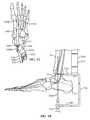
- FIG. 1Ais a posterior elevational view of an ankle fusion device including a nail in accordance with an exemplary embodiment of the present invention shown implanted in a semi-transparent skeleton;
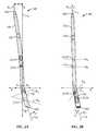
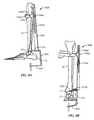
- FIG. 1Bis a lateral elevational view of the nail shown in FIG. 1A ;
- FIG. 2Ais a lateral elevational view of the nail of FIG. 1A ;
- FIG. 2Bis an anterior elevational view of the nail of FIG. 1A ;
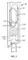
- FIG. 3is a partial perspective view of a distal portion of the nail of FIG. 1A illustrating the use of a compression screw in accordance with an exemplary embodiment of the present invention
- FIG. 4is an exploded perspective view of the compression screw of FIG. 3 and end caps for use with the ankle fusion device of FIG. 1A ;
- FIG. 5is a posterior perspective view of a guidewire targeting device in accordance with an exemplary embodiment of the present invention.
- FIG. 6is a ventral or bottom plan view of a guidewire template in accordance with an exemplary embodiment of the present invention.
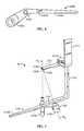
- FIG. 7is a perspective view of the guidewire targeting device of FIG. 5 in use with a guidewire template of FIG. 6 showing first and second guidewire axes;
- FIG. 8Ais a lateral elevational view of the guidewire targeting device of FIG. 5 in use upon initial insertion;
- FIG. 8Bis an anterior elevational view of the guidewire targeting device shown in FIG. 8A ;
- FIG. 8Cis an enlarged lateral elevational view of the guidewire targeting device shown in FIG. 8A ;
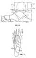
- FIG. 9is a dorsal or top plan view of a target on the talar dome of the talus
- FIG. 10is a lateral elevational view of the guidewire targeting device shown in FIG. 8A in use with a first guidewire;
- FIG. 11is a ventral or bottom plan view of the guidewire targeting device and guidewire template of FIG. 7 in use with the first and second guidewires;
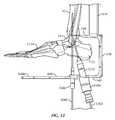
- FIG. 12is a lateral elevational view of the guidewire targeting device and guidewire template shown in FIG. 11 ;
- FIG. 13is a lateral elevational view of a cannulated drill being used with the second guidewire in accordance with an exemplary embodiment of the present invention
- FIG. 14is a lateral elevational view of the second guidewire and cannulated drill of FIG. 13 and a protection sleeve in accordance with an exemplary embodiment of the present invention
- FIG. 15is a lateral elevational view of a reamer being used in accordance with an exemplary embodiment of the present invention.
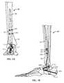
- FIG. 16is a lateral elevational view of a nail being inserted using an insertion handle in accordance with an exemplary embodiment of the present invention
- FIG. 17is a medial elevational view of a calcaneus screw being inserted using an aiming arm in accordance with an exemplary embodiment of the present invention
- FIG. 18is a medial elevational view of a talar screw being inserted using an aiming arm in accordance with an exemplary embodiment of the present invention
- FIG. 19is a posterior elevational view of a first tibial screw being inserted using an aiming arm in accordance with an exemplary embodiment of the present invention.
- FIG. 20is an anterior elevational view of a second tibial screw being inserted using an aiming arm in accordance with an exemplary embodiment of the present invention
- FIG. 21is a medial elevational view of a compression system of the ankle fusion device of FIG. 1 ;
- FIG. 22is a medial elevational view of end cap sleeve and end cap screw of FIG. 4 being inserted in the ankle fusion device of FIG. 1A ;
- FIG. 23Ais a medial elevational view of the implanted ankle fusion device of FIG. 1A ;
- FIG. 23Bis a lateral elevational view of the implanted ankle fusion device of FIG. 1A ;
- FIG. 23Cis an anterior elevational view of the implanted ankle fusion device of FIG. 1A ;
- FIG. 23Dis a posterior elevational view of the implanted ankle fusion device of FIG. 1A ;
- FIG. 24is a medial elevational view of the implanted nail of FIG. 1A attached to an extraction tool in accordance with an exemplary embodiment of the present invention.
- FIGS. 1A-24an ankle fusion device, generally designated 10 , and various instrumentation for implanting the same, in accordance with exemplary embodiments of the present invention.
- Severe arthrosis and deformity of the ankle and subtalar jointsmay be debilitating problems that can be difficult to treat.
- Tibotalocalcaneal fusionfusion of the calcaneus, talus and tibia
- Ankle arthrodesismay be a challenging procedure due to poor host conditions (e.g., bad skin, deformity, and avascular necrosis), inability to get adequate fixation for this slow healing process, and the inability to get adequate compression across the fusion.
- Performing an ankle arthrodesiscan also be technically demanding because of the shape and small size of the talus and calcaneus.
- known methods of installing ankle arthrodesesmay limit the optimal configuration of the nail and fixation screws.
- Embodiments of ankle fusion device 10are configured and shaped to obtain more optimal bony purchase in the calcaneus 12 and talus 14 and/or increase comfort.
- ankle fusion device 10obtains more optimal bony purchase and/or increase comfort by more accurately approximating the anatomy of the lower limb and using the instrumentation and methods described below to prepare the bones for implanting ankle fusion device 10 .
- the embodiments disclosed below and shown in the drawingsare for the left ankle. If not otherwise mentioned below, ankle fusion device 10 , the instrumentation and methods are mirrored across the sagittal plane of the body for the right ankle.
- an exemplary ankle fusion device 10is shown implanted within the calcaneus 12 , talus 14 and tibia 16 of a patient.
- Ankle fusion device 10includes a nail 18 and a plurality of fasteners 20 .
- Fasteners 20may include any fastening device such as but not limited to pegs, nails, wires, screws, fixation screws, bone screws and locking screws.
- nail 18is constructed from titanium, stainless steel, alloy, ceramic, and/or other solid biocompatible material.
- nail 18is substantially rigid.
- at least a portion of an exterior surface of nail 18is treated to improve biocompatibility and/or osteointegration (e.g., textured, titanium plasma spray coating, hydroxyapatite coating, etc.).
- Nail 18includes a proximal portion 18 a having an axis A 1 generally extending along, or in the direction of, a first longitudinal axis L 1 that corresponds to the general vertical center of tibia 16 (or in other words, proximal portion 18 a is generally perpendicular to a transverse plane of the patient).
- Proximal portion 18 aincludes a proximal end 18 b and at least one fastener hole (e.g., fastener hole 222 c ) for receiving a fastener 20 .
- Nail 18also includes a distal portion 18 c extending to a distal end 18 d from proximal portion 18 a along a second longitudinal axis L 2 co-axially aligned with axis A 2 .
- Second longitudinal axis L 2is oriented at an oblique angle relative to first longitudinal axis L 1 .
- nail 18extends laterally and proximally downwardly or ventrally through the calcaneus once implanted.
- nail 18also arcs anteriorly as it extends upwardly through the tibia 16 such that at least a portion of proximal portion 18 a is arcuate. In one embodiment, the entire proximal portion 18 a is arcuate. In one embodiment first longitudinal axis L 1 is tangent to the distal most end of axis A 1 of proximal portion 18 a . Having an arcuate proximal portion 18 a may help in positioning and/or fixing nail 18 within the canal of tibia 16 .
- proximal portion 18 ahas an arcuate curve such that proximal end 18 b is spaced a distance d p from first longitudinal axis L 1 in a first direction d 1 . In one embodiment, distance d p is about 36 mm for a 300 mm long nail 18 . In one embodiment, proximal portion 18 a has a radius of curvature of about 1.5 m. In one embodiment, the radius of curvature of proximal portion 18 a is generally equal to the radius of curvature of an anterior tibial canal surface.
- proximal end 18 bis spaced a distance d p from first longitudinal axis L 1 in a first direction d 1 and second longitudinal axis L 2 is oriented at oblique angles in second and third directions d 2 , d 3 relative to first longitudinal axis L 1 .
- second direction d 2is perpendicular to first direction d 1 and third direction d 3 is opposite first direction d 1 .
- first direction d 1corresponds to a forward or anterior direction
- second direction d 2corresponds to an outward or lateral direction
- third direction d 3corresponds to a rear or posterior direction relative to the ankle.
- proximal portion 18 ais substantially straight. In one such embodiment, proximal portion 18 a is co-axial with first longitudinal axis L 1 .
- proximal portion 18 aextends into tibia 16
- distal portion 18 cextends through calcaneus 12
- first direction d 1is in an anterior direction
- second direction d 2is in a lateral direction
- third direction d 3is in a posterior direction.
- proximal end 18 bis tapered or pointed, in order to facilitate insertion into the canal of tibia 16 .
- proximal end 18 bis tapered and configured to prevent a stress concentration on the canal of tibia 16 once nail 18 is implanted that may otherwise be caused by a nail end having a sharp edge.
- proximal end 18 bis a blunt or rounded tip.
- proximal end 18 bis closed.
- nail 18has a generally circular cross section throughout its length. In alternative embodiments, nail 18 may have any cross section shape including but not limited to square, star, rectangular and triangular. In one embodiment, nail 18 has a plurality of sections that decrease in diameter toward a proximal end 18 b . In some embodiments, nail 18 tapers or decreases in cross sectional size between distal portion 18 c and proximal portion 18 a . In some embodiments, distal portion 18 c has a larger diameter than the largest diameter of proximal portion 18 a . In one embodiment, distal portion 18 c has a substantially constant diameter. In one embodiment, distal portion 18 c has a diameter of about 8 mm to about 18 mm. In one embodiment, distal portion 18 c has a diameter of about 13 mm.
- proximal portion 18 aincludes a smaller diameter section and a larger diameter section.
- the smaller diameter sectionis about 7 mm to about 11 mm. In one embodiment, the smaller diameter section is about 9 mm. In one embodiment, the larger diameter section is about 10 mm. In one embodiment, the larger diameter section is about 11.5 mm. In one embodiment, the larger diameter section is about 13 mm. In some embodiments, at least a portion of the larger diameter section is hollow. In some embodiments, the smaller diameter section is not hollow. In some embodiments, the smaller diameter section is proximal to the larger diameter section and distal to proximal end 18 b . In some embodiments, nail 18 is substantially solid. In some embodiments, nail 18 is hollow or cannulated.
- proximal portion 18 aincludes a frustoconical section 18 h providing a transition between the larger diameter section and the smaller diameter section of the proximal portion 18 a .
- frustoconical section 18 his located at or proximate the center of the proximal portion 18 a (e.g., about midway along the length of proximal portion 18 a ).
- the smaller diameter sectionis shorter than the larger diameter section.
- the smaller diameter sectionis longer than the larger diameter section. in some embodiments, the smaller diameter section and the larger diameter section have lengths that are substantially equal. In some embodiments, nail 18 has a length of about 200 mm to about 300 mm.
- distal portion 18 cis configured to be positioned, at least partially, in talus and calcaneus bones 14 , 12 of an ankle of the patient. In some embodiments, distal portion 18 c is oriented at an oblique angle relative to proximal portion 18 a to maximize purchase of distal portion 18 c in talus 14 and calcaneus 12 upon implantation of ankle fusion device 10 . In some embodiments, distal portion 18 c is configured to be positioned in talus 14 and calcaneus 12 so as to generally pass through the center of talus 14 and calcaneus 12 .
- distal portion 18 cupon implantation, is angled posteriorly and/or laterally relative to proximal portion 18 a . In some embodiments, upon implantation, distal portion 18 c is angled posteriorly and/or laterally relative to a longitudinal axis of the tibia bone.
- second longitudinal axis L 2is oriented at an oblique angle relative to first longitudinal axis L 1 in third direction d 3 at an angle ⁇ of about 15 degrees as projected on to a coronal or x-y plane as shown in FIG. 2A .
- second longitudinal axis L 2is oriented at an oblique angle from first longitudinal axis L 1 in second direction d 2 at an angle ⁇ of about 10 degrees as projected on to a sagittal or y-z plane as shown in FIG. 2B .
- angle ⁇may be about 5 degrees, about 6 degrees, about 7 degrees, about 8 degrees, about 9 degrees, about 10 degrees, about 11 degrees, about 12 degrees, about 13 degrees, about 14 degrees, exactly 15 degrees, about 16 degrees, about 17 degrees, about 18 degrees, about 19 degrees, about 20 degrees, about 21 degrees, about 22 degrees, about 23 degrees, about 24 degrees, about 25 degrees.
- angle 0may be about 1 degree, about 2 degrees, about 3 degrees, about 4 degrees, about 5 degrees, about 6 degrees, about 7 degrees, about 8 degrees, about 9 degrees, exactly 10 degrees, about 11 degrees, about 12 degrees, about 13 degrees, about 14 degrees, about 16 degrees, about 17 degrees, about 18 degrees, about 19 degrees, about 20 degrees.
- fastener holes 22e.g., 222 a , 222 b , 222 c , 222 d ) extending through nail 18 are spaced along the length of nail 18 and are configured to receive fasteners 20 .
- ankle fusion device 10includes a plurality of through holes or fastener holes 22 , at least two of which being positioned at different locations along the length of nail 18 , such that one of the at least two fastener holes 22 is positioned on nail 18 proximally or distally relative to the other fastener hole 22 .
- the ankle fusion device 10includes a plurality of fastener holes 22 , at least two of which are positioned at different radial locations about first and/or second longitudinal axes L 1 , L 2 of nail 18 .
- one or more fastener holes 22are positioned such that the central axes (see e.g., A 3 -A 6 ) of each fastener hole 22 are substantially perpendicular to first and/or second longitudinal axis L 1 , L 2 of nail 18 .
- one or more fastener holes 22are oriented such that the central axes (e.g., A 3 -A 6 ) through the one or more fastener holes 22 are not perpendicular to first and/or second longitudinal axis L 1 , L 2 of nail 18 .
- ankle fusion device 10includes a plurality of fastener holes 22 , at least two of which are differently sized. In some embodiments, ankle fusion device 10 includes a plurality of fastener holes 22 , at least two of which are substantially the same size.
- At least some fastener holes 22may have elongate openings, for example, elongated in a distal-proximal direction such that a fastener 20 positioned in such a fastener hole 22 is capable of shifting proximally or distally within the fastener hole 22 .
- at least some of fastener holes 22e.g, fastener hole 222 c may have substantially circular openings.
- a first fastener hole 222 ais configured to receive a first fastener 20 a for securing nail 18 to calcaneus 12 that is substantially co-axially aligned with a longest dimension of calcaneus 12 as shown.
- first fastener hole 222 ais aligned with a central portion of calcaneus 12 .
- first fastener hole 222 amay be configured and oriented to have a central axis A 4 substantially co-axially aligned with a central longitudinal axis of calcaneus 12 .
- first fastener 222 aCo-axial alignment of central axis A 4 with a central portion of the calcaneus bone allows first fastener 222 a , in some embodiments, to find greater purchase in calcaneus 12 and to permit a stronger securement thereto.
- the central longitudinal axis of calcaneus 12generally extends in an anterior direction.
- first fastener 20 ahas a length substantially matching the length of calcaneus 12 along a central longitudinal axis of calcaneus 12 . In some embodiments, first fastener 20 a is about 70 mm to about 100 mm.
- a second fastener hole 222 bis configured to receive a second fastener 20 b for securing nail 18 to talus 14 that is substantially co-axially aligned with a longest dimension of talus 14 as shown.
- second fastener hole 222 bmay be configured (e.g., angled) to have a central axis A 3 substantially co-axially aligned with a central longitudinal axis of talus 14 .
- the central longitudinal axis of talus 14generally extends in an anterior direction.
- the central longitudinal axis of talus 14generally extends in an anterior-medial direction.
- second fastener 20 bCo-axial alignment of the second fastener hole 222 b with a central portion of the talus bone allows the second fastener 20 b , in some embodiments, to find greater purchase in the talus 14 and to permit a stronger securement thereto.
- the central longitudinal axis of talus 14generally extends in an anterior-lateral direction.
- second fastener 20 bhas a length substantially matching the length of talus 14 along a central longitudinal axis of the talus 14 . In some embodiments, second fastener 20 b is about 46 mm to about 80 mm.
- the central axes of the first and second elongate fastener holes 222 a , 222 bare divergent (e.g., as they extend anteriorly), such that the central axes are not parallel and/or not coplanar.
- the first elongate fastener hole 222 amay have a different (e.g., larger) dimension than the second elongate fastener hole 222 b , for example, so as to accept larger fasteners and/or permit greater shifting of the fastener.
- first fastener hole 222 ais elongated such that first fastener 20 a can be translated proximally with respect to second longitudinal axis L 2 while being parallel with axis A 4 .
- axis A 4is about 25 degrees to about 35 degrees relative to second longitudinal axis L 2 .
- axis A 4is about 30 degrees relative to second longitudinal axis L 2 .
- second fastener hole 222 bis elongated such that second fastener 20 b can be translated with respect to second longitudinal axis L 2 while being parallel with axis A 3 .
- axis A 3is about 85 degrees to about 95 degrees relative to second longitudinal axis L 2 . In one embodiment, axis A 3 is generally perpendicular to second longitudinal axis L 2 . In alternative embodiments, first and second fastener holes 222 a , 222 b are not elongated such that the respective fastener 20 a , 20 b generally cannot translate relative to nail 18 .
- Proximal portion 18 aincludes at least one fastener hole 22 .
- proximal portion 18 a of nail 18includes a locking or static fastener hole 222 c .
- the locking fastener hole 222 cis configured to receive a third fastener 20 c and sized to substantially prevent translational movement of third fastener 20 c relative to nail 18 .
- proximal portion 18 a of nail 18includes a dynamic fastener hole 222 d .
- dynamic fastener hole 222 dis elongated such that nail 18 can be translated proximally with respect to a fourth fastener 20 d extending through dynamic fastener hole 222 d .
- fourth fastener 20 dis installed toward the proximal end of dynamic fastener hole 222 d such that nail 18 is substantially prevented from moving distally with respect to tibia 16 but allows for a predetermined amount of proximal movement to allow for, for example, additional compression of the ankle joint.
- Either one of or both third fastener 20 c and fourth fastener 20 dmay be used depending on whether it is desired to fix nail 18 relative to tibia 16 .
- dynamic fastener hole 222 dhas an axis A 5 such that fourth fastener 20 d can be translated distally with respect to first longitudinal axis L 1 while being parallel with axis A 5 .
- axis A 5is substantially perpendicular to first longitudinal axis L 1 in the coronal or x-y plane as shown in FIG. 2B .
- locking fastener hole 222 chas an axis A 6 that is substantially aligned with third fastener 20 c .
- axis A 6is substantially perpendicular to first longitudinal axis L 1 in the coronal or x-y plane as shown in FIG. 2 B.
- axes A 5 and A 6are substantially parallel to one another.
- axes A 5 and A 6may be oriented at oblique angles with respect to first longitudinal axis L 1 and/or each other.
- nail 18may include a compression mechanism to move two or more of calcaneus 12 , talus 14 and tibia 16 closer together.
- nail 18includes a bore 18 e extending proximally from distal end 18 d along second longitudinal axis L 2 .
- bore 18 eis at least partially threaded.
- Ankle fusion device 10may include a compression screw 324 .
- compression screw 324is configured to be received in bore 18 e and translate therein along second longitudinal axis L 2 .
- compression screw 324includes an engagement portion 324 a having a concave surface configured to contact first fastener 20 a when first fastener 20 a is received in first fastener hole 222 a .
- engagement portion 324 aincludes a projection 324 b extending into a groove 18 f in the bore 18 e to prevent the engagement portion 324 a from rotating about the second longitudinal axis L 2 as the engagement portion 324 a translates proximally up bore 18 e .
- bore 18 eincludes a projection that is received in a corresponding groove in engagement portion 324 a.
- the compression screw 324includes a threaded portion 324 c attachable to engagement portion 324 a .
- Threaded portion 324 cincludes threads configured to engage the threads of bore 18 e.
- threaded portion 324 cis rotatably attached to engagement portion 324 a .
- threaded portion 324 cincludes an engagement member 324 d such as, for example a hexagon socket or slot, for mating with a screw driver tool 326 .
- compression screw 324advances proximally through bore 18 e and translates first fastener 20 c proximally (e.g., across first fastener hole 222 a ).
- first fastener 20 ais fixed relative to calcaneus 12 and at least one of third and fourth fasteners 20 c , 20 d keep nail 18 from being pulled distally, advancing compression screw 324 moves calcaneus 12 proximally toward talus 14 .
- bore 18 eextends entirely through distal portion 18 c . In one embodiment, bore 18 e extends substantially through the entire nail 18 such that nail 18 is generally hollow. In some embodiments, bore 18 e extends at least partially through distal portion 18 c . In an alternative embodiment, bore 18 e extends only through distal portion 18 c that is distal to first fastener hole 222 a.
- ankle fusion device 10includes, in one embodiment, an end cap screw 428 for closing bore 18 e after implantation and compression.
- end cap screw 428is threaded for engagement of the threads in bore 18 e .
- end cap screw 428is not threaded and instead snap fits into bore 18 e.
- distal end 18 d of nail 18includes a groove or step 18 g for engaging and orienting tools about and relative to second longitudinal axis L 2 as described in further detail below.
- ankle fusion device 10may include an end cap sleeve 430 .
- End cap sleeve 430includes one or more projections 430 a on a proximal end that are configured to align with groove 18 g and an end surface 430 b on a distal end that forms the distal most end of ankle fusion device 10 .
- end surface 430 bis configured to be substantially flush with the surrounding calcaneus 12 and with the end cap screw 428 , proximate the end of bore 18 e.
- a pathis created, e.g., by advancing (e.g., drilling) a hole proximally starting from the bottom of calcaneus 12 .
- one or more guidewiresare inserted through the calcaneus 12 , talus 14 and tibia 16 to fix reference axes for forming a path for nail 18 .
- a guidewire targeting device 534is used in implanting ankle fusion device 10 .
- the guidewire targeting device 534may eliminate the need for less accurate freehand guidewire insertion techniques that are typically used to install an ankle arthrodesis.
- Guidewire targeting device 534may use the orientation of the patient's anatomy (e.g., tibia 16 , talus 14 and/or foot) to position at least one cutting apparatus (e.g., guidewire 1060 ) up through calcaneus 12 , talus 14 and tibia 16 (see FIG. 10 ).
- guidewire targeting device 534is configured to account for the posterolateral bend of nail 18 as described above and sets the proper orientation for the drilling and placement of nail 18 .
- guidewire targeting device 534includes a frame 536 for at least partially surrounding the calcaneus 12 and talus 14 .
- frame 536includes a target arm 538 having a guidewire target 538 a configured and dimensioned to be inserted between talus 12 and tibia 16 proximate a talar dome 14 a (see FIGS. 8 c and 9 ) of talus 14 .
- first sleeve arm 540is positioned distally from calcaneus 12 when the guidewire target 538 a is inserted between talus 14 and tibia 16 proximate talar dome 14 a .
- guidewire target 538 ais a semi-circular indentation in the distal end of target arm 538 .
- guidewire target 538 aincludes a marker that is visible using an imaging device such as but not limited to a radio-marker that is visible using an imaging device and/or a guide such as a slot, a hole or a projection.
- target arm 538includes one or more downwardly extending projections 538 b used to aid in aligning guidewire target 538 a with a center or apex 14 b of talar dome 14 a .
- projections 538 binclude a pair of projections 538 b positioned on either side of guidewire target 538 a .
- the distal end of target arm 538is thinner than the remainder of the frame 536 such that target arm 538 fits more easily between talus 14 and tibia 16 while maintaining the strength of the remainder of frame 536 .
- frame 536includes a first sleeve arm 540 .
- first sleeve arm 540includes a proximal side facing towards target arm 538 and a distal side opposite the proximal side.
- frame 536is substantially C-shaped.
- frame 536is bent or at least arcuate such that target arm 538 extends above talar dome 14 a while first sleeve arm 540 extends under calcaneus 12 .
- target arm 538 and first sleeve arm 540are substantially parallel.
- first sleeve arm 540includes a first guidewire sleeve 542 .
- first guidewire sleeve 542is integral with first sleeve arm 540 .
- first guidewire sleeve 542is detachable from first sleeve arm 540 .
- first guidewire sleeve 542is positioned at or proximate a free end of first sleeve arm 540 .
- at least a portion of first guidewire sleeve 542extends from the proximal side of first sleeve arm 540 .
- first guidewire sleeve 542extends from the distal side of first sleeve arm 540 . In one embodiment, first guidewire sleeve 542 extends from the proximal side and the distal side of first sleeve arm 540 . In one embodiment, first guidewire sleeve 542 is fixed in position relative to guidewire target 538 a . In one embodiment, a central longitudinal axis of first guidewire sleeve 542 is configured to co-axially align with first guidewire axis A 7 . In one embodiment, first guidewire sleeve 542 is fixed in position relative to target arm 538 . In one embodiment, first guidewire sleeve 542 is radially disposed about first guidewire axis A 7 . In one embodiment, first guidewire axis A 7 is aligned with guidewire target 538 a.
- guidewire targeting device 534may be aligned with and/or attached to at least one anatomical feature of the patient.
- the at least one anatomical featureis tibia 16 .
- guidewire targeting device 534includes a tibial member or alignment guide 544 .
- tibial alignment guide 544is engaged with frame 536 and is configured to extend proximally therefrom along a longitudinal axis substantially parallel to the first guidewire axis A 7 .
- tibial alignment guide 544is attached to target arm 538 .
- tibial alignment guide 544is moveably attached to frame 536 using a fastener 544 b .
- tibial alignment guide 544is moveably attached to frame 536 using a star grind fastener such that tibial alignment guide 544 may be positioned relative to tibia 16 and frame 536 may be independently rotated about first longitudinal axis L 1 and then locked in position relative to tibial alignment guide 544 once in the appropriate position.
- the position of frame 536 relative to tibial alignment guide 544is adjustable but generally set by the surgeon prior to attaching to the patient.
- the position of frame 536 relative to tibial alignment guide 544is adjustable once guidewire targeting device 534 has been attached to the patient.
- the position of frame 536 relative to tibial alignment guide 544is radially adjustable.
- transverse member 546is fixed to frame 536 .
- tibial alignment guide 544may include a transverse member 546 .
- transverse member 546extends generally perpendicularly from tibial alignment guide 544 .
- transverse member 546is configured to have a curvature about first guidewire axis A 7 , such that the transverse member 546 wraps at least partially around the leg during use.
- the transverse member 546is positionable at different locations along a length of tibial alignment guide 544 to aid in aligning first guide wire axis A 7 with first longitudinal axis L 1 during use as described further below.
- tibial alignment guide 544includes a longitudinal slot 544 a extending at least partially along a length of tibial alignment guide 544 .
- transverse member 546includes a fastener 546 a such as a screw knob that extends through longitudinal slot 544 a .
- transverse member 546may be movable attached to or fixedly attached but moveable relative to tibial alignment guide 544 in any manner.
- tibial alignment guide 544instead of a longitudinal slot 544 a , tibial alignment guide 544 includes a plurality of holes.
- transverse member 546is fixed relative to or integral with tibial alignment guide 544 .
- transverse member 546is bendable or conformable such that the surgeon can shape transverse member 546 to the shape of the patient's leg.
- transverse member 546includes an attachment member (not shown) such as, for example, a Velcro strap and/or elastic band that is configured to attached to the patient's leg.
- frame 536 and/or transverse member 546may be attached to tibial alignment guide 544 in the opposite facing direction for use with the right ankle.
- frame 536 and/or tibial alignment guide 544includes indicia (not shown) to indicate the proper orientation of or connection between components of guidewire targeting device 534 for the left and right foot.
- frame 536 and/or transverse member 546includes indicia (not shown) to indicate the general position frame 536 should be oriented to tibial alignment guide 544 depending on the position of the patient during surgery.
- transverse member 545includes indicia 546 b , 546 c to indicate the proper orientation for the left and right foot.
- transverse member 546is shaped for use when the patient is in the supine position.
- a differently shaped transverse member 546may be provided for patients in the prone position.
- a single transverse member 546is provided and frame 536 may be attached to tibial alignment guide 544 in a radial orientation relative to tibial alignment guide 544 depending on the position of the patient.
- transverse member 546includes a first alignment member 546 d for aligning with the first longitudinal axis L 1 and/or first guidewire 1060 as described further below. In one embodiment, transverse member 546 includes a second alignment member 546 e for aligning with first longitudinal axis L 1 and/or first guidewire 1060 . In one embodiment, first and/or second alignment members 546 d , 546 e are configured and positioned to intersect with a plane aligned with the first guidewire axis A 7 . In one embodiment, first and second alignment members 546 d , 546 e include indents or bends in the transverse member 546 .
- first and second alignment members 546 d , 546 einclude one or more projections and/or grooves in the transverse member 546 .
- first and second alignment members 546 d , 546 einclude a marker that is visible using an imaging device such as but not limited to a radio-marker that is visible using an imaging device.
- the horizontal thickness of first and second alignment members 546 d , 546 eis generally equal to a thickness of first guidewire 1060 .
- first alignment member 546 dis positioned along the length of transverse member 546 such that first alignment member 546 d aligns with first longitudinal axis L 1 from a lateral view of tibia 16 and second alignment member 546 e is positioned along the length of transverse member 546 e such that second alignment member 546 e aligns with first longitudinal axis L 1 from an anterior view of tibia 16 .
- aligning first and second alignment member 546 e with first longitudinal axis L 1 from two directionshelps to ensure that tibial alignment guide 534 is substantially parallel with first longitudinal axis L 1 .
- guidewire targeting device 534may include a second guidewire template 648 for use with a second guidewire 1262 .
- Second guidewire template 648is configured to align a second guidewire axis A 8 with the guidewire target 538 a .
- Second guidewire template 648includes a second position sleeve 648 a radially disposed about a second guidewire axis A 8 .
- first guidewire sleeve 542is used to co-axially align first guidewire axis A 7 with first longitudinal axis L 1 and second position sleeve 648 a is used to co-axially align second guidewire axis A 8 with the desired position of second longitudinal axis L 2 .
- guidewire targeting device 534is configured to position second longitudinal axis L 1 .
- guidewire targeting device 534is configured to align first longitudinal axis L 1 with the central longitudinal axis of tibia 16 and guidewire targeting device 534 is configured to position second longitudinal axis L 2 in a preselected orientation with respect to the position of first longitudinal axis L 1 .
- the preselected orientationis based on the shape of nail 18 .
- Second guidewire template 648may be integral, moveable and/or detachable with frame 536 .
- second guidewire template 648is removably attached to first sleeve arm 540 .
- second guidewire template 648is positioned distally with respect to frame 536 .
- second guidewire template 648is configured to abut the distal side of first sleeve arm 540 .
- second guidewire template 648is positioned such that at least a portion of first sleeve arm 540 is located between second guidewire template 648 and target arm 538 .
- second guidewire template 648is positioned between target arm 538 and first sleeve arm 540 .
- second guidewire template 648includes an attachment sleeve 648 c .
- attachment sleeve 648 cis configured and dimensioned to engage with at least a portion of first guidewire sleeve 542 .
- attachment sleeve 648 cis configured to engage with a portion of first guidewire sleeve 542 that extends from the distal side of first sleeve arm 540 .
- attachment sleeve 648 cis compression fit over first guidewire sleeve 542 such that attachment sleeve 648 c is moveable with respect to first guidewire sleeve 542 but remains in place relative to first guidewire sleeve 542 after first guidewire sleeve 542 is positioned and released by the surgeon.
- attachment sleeve 648 csnap fits onto first guidewire sleeve 542 such that movement of attachment sleeve 648 c is retained along first guidewire axis A 7 but is free to rotate about first guidewire axis A 7 .
- second position sleeve 648 ais configured to rotate about first guidewire axis A 7 .
- second position sleeve 648 ais translatable along an arc about first guidewire axis A 7 .
- second position sleeve 648 ais configured to be a retainer for receiving and aligning a second guidewire sleeve 1252 (see, e.g., FIG. 12 ) along second guidewire axis A 8 .
- second guidewire sleeve 1252is integral with second position sleeve 648 a.
- Second guidewire template 648may include an alignment arm 648 b for positioning second guidewire axis A 8 relative to first longitudinal axis L 1 by aligning alignment arm 648 b relative to an anatomical feature of the patient.
- alignment arm 648 bmay be used to position second guidewire axis A 8 relative to first guidewire axis A 7 and relative to first longitudinal axis L 1 by aligning alignment arm 648 b relative to an anatomical feature of the patient.
- second guidewire template 648is configured such that second guidewire axis A 8 is substantially aligned with guidewire target 538 a and/or center 14 b of talar dome 14 a when alignment arm 648 b is aligned with a pre-selected anatomical feature of the patient.
- alignment arm 648 bextends generally perpendicularly from first guidewire axis A 7 .
- the pre-selected anatomical feature aligned with the alignment arm 648 bis generally perpendicular to the central axis of tibia 16 (i.e., first longitudinal axis L 1 ).
- the pre-selected anatomical featureis a second metatarsal bone 1150 (see FIG.
- alignment arm 648 bis aligned to be substantially parallel with second metatarsal 1150 to determine the position of second guidewire axis A 8 .
- the pre-selected anatomical featureis any one of the elongated bones in the foot.
- first and second guidewires 1060 , 1262may be used to properly align nail 18 with the patient's anatomy.
- first guidewire 1060is generally aligned with first longitudinal axis L 1 (e.g., the central longitudinal axis of tibia 16 ) and second guidewire 1262 is generally aligned with the position of second longitudinal axis L 2 once nail 18 is implanted (e.g., at an oblique angle relative to first longitudinal axis L 1 ).
- first and second guidewires 1060 , 1262are used in order to form a cutting path corresponding to the bent shape of nail 18 using two generally straight lines.
- a single guidewiremay be used if the guidewire bends during insertion or if the foot is positioned such that the paths for the first and second longitudinal axes L 1 , L 2 are co-axially aligned during insertion of the guidewire.
- first and second guidewires 1060 , 1262allows for more accurate alignment with first and second longitudinal axes L 1 , L 2 since first guidewire 1060 is used to co-axially align with first longitudinal axis L 1 using anatomical features such as the talar dome 14 a and the tibia 16 and the second wire 1262 can be positioned relative to the first guidewire 1062 (or the path created by the first guidewire).
- the position of the patientmay be determined based on the type of arthrodesis procedure performed and the discretion of the surgeon.
- the patientis placed in the prone position.
- the patientis placed in the supine position.
- guidewire targeting device 534is placed in the posterior (not shown) or posterolateral position (the position shown in the exemplary embodiment of FIGS. 8A-12 ).
- the guidewire targeting device 534may be placed in the anterolateral position.
- the footmay be oriented relative to tibia 16 in the position that the ankle is to be fixed in place.
- the ankleis placed in a neutral position. In other embodiments, the ankle is placed in about 2 to about 3 degrees dorsi flexion.
- guidewire target 538 ais inserted between talus 14 and tibia 16 .
- guidewire target 538 ais placed proximate talar dome 14 a (see FIG. 9 ).
- guidewire target 538 ais placed proximate center 14 b of talar dome 14 a .
- guidewire target 538 ais positioned generally directly above center 14 b of talar dome 14 a .
- center 14 b of talar dome 14 ais aligned with first longitudinal axis L 1 and the central axis of tibia 16 .
- projections 538 bare positioned on either side of center 14 b of talar dome 14 a .
- the position of guidewire target 538 a relative to talus 14is viewed using imaging such as fluoroscopic imaging.
- first guidewire sleeve 542is positioned under calcaneus such that first guidewire axis A 7 generally aligns with guidewire target 538 a . In one embodiment, first guidewire sleeve 542 is positioned so that first guidewire sleeve 542 aligns exactly with guidewire target 538 a . In one embodiment, first guidewire sleeve 542 is positioned so that first guidewire axis A 7 is aligned with center 14 b of talar dome 14 a.
- tibial alignment guide 544is used to help align the first guidewire axis A 7 with first longitudinal axis L 1 by positioning tibial alignment guide 544 substantially parallel with tibia 16 .
- first alignment member 546 d and/or second alignment member 546 eare aligned with first longitudinal axis L 1 in the lateral and anterior views, respectively, to position tibial alignment guide 544 substantially parallel with tibia 16 .
- tibial alignment guide 544is positioned relative to first longitudinal axis L 1 by sliding or otherwise positioning transverse member 546 along the length of tibial alignment guide 544 and in contact with the outer surface of the leg.
- transverse member 546prevents guidewire targeting device 534 from moving with respect to the patient.
- guidewire targeting device 534would pivot laterally and posteriorly relative to guidewire target 538 a caused by the weight of guidewire targeting device 534 .
- transverse member 546counters any pivot of guidewire targeting device 534 with respect to the guidewire target 538 a .
- moving transverse member 546 along the length of tibial alignment guide 544alters the orientation of first guidewire axis A 7 in a first plane until first guidewire axis A 7 is aligned with first longitudinal axis L 1 .
- the curvature of transverse member 546keeps first guidewire axis A 7 aligned with first longitudinal axis L 1 in a second plane, the second plane being generally perpendicular to the first plane.
- first guidewire 1060is advanced proximally through first guidewire sleeve 542 , along first guide wire axis A 7 , through calcaneus 12 and talus 14 and into the distal end of tibia 16 .
- the placement and guidance of first guidewire 1060is monitored using the imaging device.
- the guidance of first guidewire 1060is monitored using the imaging device from lateral and mortise views.
- first guidewire 1060is aligned with first alignment member 546 d and/or second alignment member 546 e in the lateral and anterior views, respectively.
- Advancement of the first guidewire 1060 along first guidewire axis A 7creates a channel in the distal end of tibia 16 substantially aligned with first longitudinal axis L 1 .
- second guidewire template 648is attached to guidewire targeting device 534 .
- second guidewire template 648include indicia 648 d (see FIG. 6 ) such as the word “Left” and/or color coding to indicate the appropriate left or right foot.
- second guidewire template 648may be positioned relative to frame 536 and/or first guidewire axis A 7 by aligning alignment arm 648 b with an anatomical feature of the patient such as second metatarsal 1150 .
- second guidewire axis A 8generally aligns with guidewire target 538 a and is co-axial with where second longitudinal axis L 2 will be. In one embodiment, once second guidewire template 648 is in place, second guidewire axis A 8 generally aligns with the anterior margin of the plantar aspect of the calcaneal tuberosity equidistant from the medial and lateral wall of calcaneus 12 .
- second guidewire sleeve 1252is inserted into second position sleeve 648 a if second guidewire sleeve 1252 is not already attached.
- second guidewire 1262is advanced proximally through second guidewire sleeve 1252 , through calcaneus 12 and talus 14 proximate the guidewire target 538 a .
- the position of second guidewire 1060 during insertionis monitored using the imaging device from lateral and mortise views.
- first guidewire 1062 and guidewire targeting device 534are removed such that only second guidewire 1262 remains.
- a cannulated drill 1356is inserted over the second guidewire 1262 .
- the guidewire targeting device 534is left in place, the second guidewire 1262 is removed and a drill is guided along second guidewire axis A 8 .
- the footis positioned such that second guidewire 1262 aligns with first longitudinal axis L 1 .
- the footis positioned such that second guidewire 1262 is substantially aligned with a longitudinal axis of tibia 16 .
- positioning the footincludes angling the foot relative to tibia 16 such that second guidewire 1262 is substantially aligned with the channel created in the distal end of tibia 16 by the first guidewire 1060 .
- second guidewire 1262is then advanced into the channel created in the distal end of tibia 16 by the first guidewire 1060 .
- a protection sleeve 1458is inserted over second guidewire 1262 to aid in positioning the foot and protects the cannulated drill 1356 .
- the footis dorsiflexed about 15 degrees and inverted 10 degrees.
- cannulated drill 1356is advanced into tibia 16 over second guidewire 1262 .
- a reamer 1564is inserted through the path created by the cannulated drill 1356 .
- a narrow tibial canalmay hinder insertion of nail 18 .
- progressive reaming of the tibial canalis performed using reamers having cross sectional widths of about 0.5 mm to about 1 mm larger than the diameter of nail 18 .
- nail 18may be inserted proximally through calcaneus 12 and talus 14 and into tibia 16 .
- an insertion handle 1666is attached to distal end 18 d of nail 18 to aid in insertion of nail 18 .
- Insertion handle 1666is configured to align with the at least one groove 18 g in nail 18 so that the radial position of insertion handle 1666 is fixed relative to distal portion 18 c of nail 18 .
- insertion handle 1666is coupled to distal portion 18 c of nail 18 using a threaded connecting screw (not shown) that extends upwardly into bore 18 e of nail 18 .
- nail 18is inserted as far as possible by gripping the insertion handle and pushing nail 18 upwardly across the ankle joint.
- a driving cap 1668may be coupled to insertion handle 1666 .
- driving cap 1668includes a distal end surface to which a force may be applied to facilitate insertion of nail 18 .
- nail 18is rotated into its final position using the driving cap 1668 and insertion handle 1666 .
- placement of nail 18is guided and monitored using the imaging device.
- an aiming arm 1870is attached to insertion handle 1666 .
- the aiming arm 1870may be used to insert some or all of fasteners 22 relative to the position of nail 18 .
- insertion handle 1666includes one or more longitudinally extending alignment features 1666 a such a groove or projection.
- alignment feature 1666 aincludes a plurality of grooves spaced circumferentially around insertion handle 1666 .
- insertion handle 1666includes a plurality of indicia 1666 b spaced radially around the insertion handle 1666 .
- indicia 1666 bare used to indicate the position of aiming arm 1870 relative to first and second longitudinal axes L 1 , L 2 .
- indicia 1666 bincludes markings such as letters that correspond to respective fasteners 20 .
- markingssuch as letters that correspond to respective fasteners 20 .
- indicia 1666 bmay show “C” through a viewing window in aiming arm 1870 to indicate that the hole marked “Calcaneus Screw” for calcaneus 12 should be used with the appropriate drill 1874 a , drill sleeve 1872 a and screw 20 a.
- first fastener 20 ais inserted into the most distal end of first fastener hole 22 a .
- second fastener 20 bis inserted into the most distal end of second fastener hole 22 b .
- third and fourth fasteners 20 c , 20 dthere are three options 1) static locking, 2) dynamic locking and 3) originally static with the option to later make dynamic.
- third fastener 20 cis inserted into third fastener hole 20 c to prevent nail 18 from moving relative to tibia 16 .
- fourth fastener 20 dis inserted into the most proximal end of fourth fastener hole 22 d . In one embodiment, if it is desired to have nail 18 be static but keep the option to later make dynamic, fourth fastener 20 d is inserted into the most proximal end of fourth fastener hole 22 d and third fastener 20 c is inserted into third fastener hole 20 c .
- Such an embodimentprevents nail 18 from moving relative to tibia 18 until third fastener 20 c is removed at which point nail 18 may move proximally up tibia 16 if calcaneus 12 and/or talus 14 are compressed further toward tibia 16 (e.g., if bone graft compresses).
- compression screw 324may be driven proximally through bore 18 e using a screw driver 326 .
- compression screw 324engages first fastener 22 a . Since calcaneus 12 is fixed relative to first fastener 22 a and nail 18 is prevented from moving distal due third and/or fourth fasteners 22 c , 22 d, the calcaneus is shifted proximally toward tibia 16 .
- both calcaneus 12 and talus 14are shifted proximally toward tibia 16 .
- end cap sleeve 430 and end cap screw 428may be inserted into distal end 18 d of nail 18 to seal bore 183 .
- FIGS. 23A-23Dillustrate an exemplary ankle fusion device 10 after installation.
- ankle fusion device 10is left implanted in the patient until calcaneus 12 , talus 14 and/or tibia 16 are sufficiently fused together.
- an extraction tool 2576may be used to assist in distracting nail 18 from the patient.
- extraction tool 2576is threadably attached to distal end 18 d of nail 18 .
- extraction tool 2576is pulled and/or hammered distally to remove nail 18 .
- kits for performing the ankle arthrodeses described hereinmay include one or more of each of the instruments, fasteners and/or implantable devices described herein.
- a kit for performing ankle arthrodesisincludes nail 18 , one or more fasteners 20 , guidewire targeting device 534 , and at least one guidewire 1060 .
- a kit for performing ankle arthrodesisincludes nail 18 , one or more fasteners 20 , guidewire targeting device 534 , first guidewire 1060 and second guidewire 1062 .
- a kit for performing ankle arthrodesisincludes guidewire targeting device 534 , and at least one guidewire 1060 .
- a kit for performing ankle arthrodesisincludes guidewire targeting device 534 , at least one guidewire 1060 , and aiming arm 1870 .
Landscapes
- Health & Medical Sciences (AREA)
- Surgery (AREA)
- Life Sciences & Earth Sciences (AREA)
- Orthopedic Medicine & Surgery (AREA)
- Biomedical Technology (AREA)
- Public Health (AREA)
- Veterinary Medicine (AREA)
- Engineering & Computer Science (AREA)
- Nuclear Medicine, Radiotherapy & Molecular Imaging (AREA)
- Heart & Thoracic Surgery (AREA)
- Medical Informatics (AREA)
- Molecular Biology (AREA)
- Animal Behavior & Ethology (AREA)
- General Health & Medical Sciences (AREA)
- Dentistry (AREA)
- Oral & Maxillofacial Surgery (AREA)
- Neurology (AREA)
- Surgical Instruments (AREA)
- Prostheses (AREA)
Abstract
Description
Claims (19)
Priority Applications (1)
| Application Number | Priority Date | Filing Date | Title |
|---|---|---|---|
| US14/031,526US9308037B2 (en) | 2009-12-11 | 2013-09-19 | Ankle fusion device, instrumentation and methods |
Applications Claiming Priority (3)
| Application Number | Priority Date | Filing Date | Title |
|---|---|---|---|
| US28414109P | 2009-12-11 | 2009-12-11 | |
| US12/965,691US8562606B2 (en) | 2009-12-11 | 2010-12-10 | Ankle fusion device, instrumentation and methods |
| US14/031,526US9308037B2 (en) | 2009-12-11 | 2013-09-19 | Ankle fusion device, instrumentation and methods |
Related Parent Applications (1)
| Application Number | Title | Priority Date | Filing Date |
|---|---|---|---|
| US12/965,691DivisionUS8562606B2 (en) | 2009-12-11 | 2010-12-10 | Ankle fusion device, instrumentation and methods |
Publications (2)
| Publication Number | Publication Date |
|---|---|
| US20140025127A1 US20140025127A1 (en) | 2014-01-23 |
| US9308037B2true US9308037B2 (en) | 2016-04-12 |
Family
ID=44145942
Family Applications (2)
| Application Number | Title | Priority Date | Filing Date |
|---|---|---|---|
| US12/965,691Active2031-05-06US8562606B2 (en) | 2009-12-11 | 2010-12-10 | Ankle fusion device, instrumentation and methods |
| US14/031,526Active2031-03-11US9308037B2 (en) | 2009-12-11 | 2013-09-19 | Ankle fusion device, instrumentation and methods |
Family Applications Before (1)
| Application Number | Title | Priority Date | Filing Date |
|---|---|---|---|
| US12/965,691Active2031-05-06US8562606B2 (en) | 2009-12-11 | 2010-12-10 | Ankle fusion device, instrumentation and methods |
Country Status (6)
| Country | Link |
|---|---|
| US (2) | US8562606B2 (en) |
| EP (1) | EP2509521B1 (en) |
| JP (1) | JP5497194B2 (en) |
| AU (1) | AU2010328001B2 (en) |
| CA (1) | CA2783553C (en) |
| WO (1) | WO2011072249A1 (en) |
Cited By (2)
| Publication number | Priority date | Publication date | Assignee | Title |
|---|---|---|---|---|
| US10610368B2 (en) | 2018-05-26 | 2020-04-07 | Acumed Llc | Ankle fusion system with expandable spacer |
| WO2021257807A1 (en)* | 2020-06-17 | 2021-12-23 | University Of Kentucky Research Foundation | Subtalar arthrodesis nail implant system |
Families Citing this family (91)
| Publication number | Priority date | Publication date | Assignee | Title |
|---|---|---|---|---|
| US8475463B2 (en)* | 2009-04-13 | 2013-07-02 | George J. Lian | Systems and instrumentalities for use in total ankle replacement surgery |
| FR2980357A1 (en)* | 2011-09-23 | 2013-03-29 | Tornier Sa | SURGICAL INSTRUMENTATION FOR CARRYING AN ARTHRODESE OF THE ANKLE AND A CORRESPONDING ANKLE ARTHRODESIS KIT |
| CH701107B1 (en)* | 2009-05-18 | 2013-11-29 | Biedermann Technologies Gmbh | Apparatus for drilling an arcuate bore. |
| US9066757B2 (en)* | 2009-08-10 | 2015-06-30 | Virak Orthopedic Research Llc | Orthopedic external fixator and method of use |
| US20120109217A1 (en)* | 2010-05-06 | 2012-05-03 | Christophe Perineau | Anterior-to-posterior talus-calcaneus screw insertion for ankle arthrodesis nail |
| CN103202725B (en)* | 2012-01-11 | 2015-09-16 | 上海市第六人民医院 | Pollex dissects locking steel plate with outside joint fusion |
| ES2552940T3 (en) | 2012-11-14 | 2015-12-03 | Biedermann Technologies Gmbh & Co. Kg | Aiming device to guide a drilling arrangement |
| EP2732783B1 (en) | 2012-11-14 | 2016-04-27 | Biedermann Technologies GmbH & Co. KG | Bone nail for the heel |
| US10105151B2 (en)* | 2012-12-12 | 2018-10-23 | Wright Medical Technology, Inc. | Instrument for intra-operative implant templating using fluoroscopy |
| US9480571B2 (en) | 2012-12-27 | 2016-11-01 | Wright Medical Technology, Inc. | Ankle replacement system and method |
| CA2836651C (en) | 2012-12-27 | 2016-03-22 | Wright Medical Technology, Inc. | Ankle replacement system and method |
| US9918724B2 (en) | 2012-12-27 | 2018-03-20 | Wright Medical Technology, Inc. | Ankle replacement system and method |
| US9974588B2 (en) | 2012-12-27 | 2018-05-22 | Wright Medical Technology, Inc. | Ankle replacement system and method |
| EP4252686A3 (en) | 2012-12-28 | 2023-12-27 | Paragon 28, Inc. | Alignment guide apparatus |
| BR112015022274A2 (en) | 2013-03-14 | 2017-07-18 | Wright Medical Tech Inc | ankle replacement system and method |
| ES2959525T3 (en)* | 2013-03-15 | 2024-02-26 | Paragon 28 Inc | intramedullary nail |
| DE102013005414A1 (en)* | 2013-03-28 | 2014-10-02 | Dietmar Wolter | Osteosynthesis system for the multidirectional, angularly stable treatment of fractures of long bones including an intramedullary nail and bone screws |
| WO2015017074A1 (en) | 2013-07-02 | 2015-02-05 | Cmarr Enterprises | Curved tibiotalar fusion nail and method of use |
| GB2530960A (en)* | 2013-07-03 | 2016-04-06 | Acute Innovations Llc | Steerable fastener for bone |
| US9132018B1 (en)* | 2013-08-27 | 2015-09-15 | Mohammed A. Hajianpour | Total ankle replacement |
| CN103876814A (en)* | 2014-02-19 | 2014-06-25 | 徐煜 | Internal fixation device for fractured calcaneus |
| USD904616S1 (en) | 2014-03-14 | 2020-12-08 | Paragon 28, Inc. | Intramedullary fastener |
| US9554916B2 (en)* | 2014-06-04 | 2017-01-31 | Sarah Miller | Apparatus and method for replacement of a metatarsophalangeal joint with interphalangeal fusion |
| US20160015426A1 (en) | 2014-07-15 | 2016-01-21 | Treace Medical Concepts, Inc. | Bone positioning and cutting system and method |
| JP6271363B2 (en)* | 2014-07-23 | 2018-01-31 | 帝人メディカルテクノロジー株式会社 | Medical screwdriver |
| US9687250B2 (en) | 2015-01-07 | 2017-06-27 | Treace Medical Concepts, Inc. | Bone cutting guide systems and methods |
| US9480506B2 (en)* | 2015-01-11 | 2016-11-01 | Mohammad Javad Zehtab | Compression device for interlocking compression nailing systems and method of use |
| WO2016134154A1 (en) | 2015-02-18 | 2016-08-25 | Treace Medical Concepts, Inc. | Pivotable bone cutting guide useful for bone realignment and compression techniques |
| US20220151664A1 (en)* | 2015-04-16 | 2022-05-19 | Texas Tech University System | Ankle (Tibio-Talar) Fusion Nail |
| US10653467B2 (en) | 2015-05-06 | 2020-05-19 | Treace Medical Concepts, Inc. | Intra-osseous plate system and method |
| US9622805B2 (en) | 2015-08-14 | 2017-04-18 | Treace Medical Concepts, Inc. | Bone positioning and preparing guide systems and methods |
| EP4483824A3 (en) | 2015-07-14 | 2025-03-05 | Treace Medical Concepts, Inc. | Bone positioning guide |
| US10849663B2 (en) | 2015-07-14 | 2020-12-01 | Treace Medical Concepts, Inc. | Bone cutting guide systems and methods |
| EP4494582A3 (en) | 2015-08-14 | 2025-04-16 | Treace Medical Concepts, Inc. | Tarsal-metatarsal joint procedure utilizing fulcrum |
| WO2017031020A1 (en) | 2015-08-14 | 2017-02-23 | Treace Medical Concepts, Inc. | Tarsal-metatarsal joint procedure utilizing fulcrum |
| CA2998481C (en) | 2015-09-18 | 2024-05-14 | Treace Medical Concepts, Inc. | Joint spacer systems and methods |
| AU2017313725B2 (en)* | 2016-08-15 | 2022-09-22 | Triqueue Holdings, Llc | Bone fusion device, system and methods |
| US10512470B1 (en) | 2016-08-26 | 2019-12-24 | Treace Medical Concepts, Inc. | Osteotomy procedure for correcting bone misalignment |
| US11083503B2 (en) | 2016-09-22 | 2021-08-10 | Globus Medical, Inc. | Systems and methods for intramedullary nail implantation |
| US10492803B2 (en) | 2016-09-22 | 2019-12-03 | Globus Medical, Inc. | Systems and methods for intramedullary nail implantation |
| EP3528716B1 (en) | 2016-10-24 | 2024-02-14 | Paragon 28, Inc. | Osteotomy systems |
| US10524808B1 (en) | 2016-11-11 | 2020-01-07 | Treace Medical Concepts, Inc. | Devices and techniques for performing an osteotomy procedure on a first metatarsal to correct a bone misalignment |
| US11547456B2 (en) | 2017-01-12 | 2023-01-10 | Dt Medtech, Llc | Internal ankle fixation systems, foot securement and jig devices, and related methods |
| US10939939B1 (en) | 2017-02-26 | 2021-03-09 | Treace Medical Concepts, Inc. | Fulcrum for tarsal-metatarsal joint procedure |
| ES2993743T3 (en) | 2017-02-27 | 2025-01-08 | Paragon 28 Inc | Targeting instruments and systems |
| EP3585287B1 (en) | 2017-02-27 | 2024-11-13 | Paragon 28, Inc. | Intramedullary nail fixation systems |
| US10918431B2 (en) | 2017-03-30 | 2021-02-16 | Paragon 28, Inc. | Bone fixation system, assembly, implants, devices, alignment guides, and methods of use |
| IT201700048446A1 (en) | 2017-05-04 | 2018-11-04 | Orthofix Srl | Improved bone screw for the treatment of sagging or bone deformation, such as in the case of the Charcot foot, and insertion instruments in the bone screw of anti-migration elements |
| CN106955146B (en)* | 2017-05-09 | 2023-05-26 | 上海市奉贤区中心医院 | Miniature fixer for calcaneus fracture |
| AU2017418982B2 (en)* | 2017-06-13 | 2020-03-12 | Wright Medical Technology, Inc. | Calcaneal prosthesis |
| EP3651699B1 (en) | 2017-07-11 | 2025-09-17 | Paragon 28, Inc. | Bone fixation system, assembly, implants, devices and insertion guides |
| FR3077476B1 (en)* | 2018-02-07 | 2022-10-21 | In2Bones | IMPROVED ARTHRODESIS DEVICE |
| ES3035609T3 (en) | 2018-04-30 | 2025-09-05 | Paragon 28 Inc | Laser-based implant alignment and resection guide systems |
| US11596443B2 (en) | 2018-07-11 | 2023-03-07 | Treace Medical Concepts, Inc. | Compressor-distractor for angularly realigning bone portions |
| EP3820382B1 (en) | 2018-07-11 | 2025-09-10 | Paragon 28, Inc. | Systems comprising alignment guides and implants |
| US11583323B2 (en) | 2018-07-12 | 2023-02-21 | Treace Medical Concepts, Inc. | Multi-diameter bone pin for installing and aligning bone fixation plate while minimizing bone damage |
| CN109394329B (en)* | 2018-12-07 | 2024-03-19 | 昆明医科大学第二附属医院 | Ankle joint fuses puts nail director |
| WO2020123899A1 (en) | 2018-12-13 | 2020-06-18 | Paragon 28, Inc. | Alignment instruments and methods for use in total ankle replacement |
| EP3893765A4 (en) | 2018-12-13 | 2023-03-29 | Paragon 28, Inc. | Total ankle replacement surgical method |
| EP3893772A4 (en) | 2018-12-13 | 2022-11-23 | Paragon 28, Inc. | RESECTION GUIDES, SCAN REAMERS AND METHODS FOR USE IN TOTAL ANKLE REPLACEMENT |
| EP3893767B1 (en) | 2018-12-13 | 2025-07-23 | Paragon 28, Inc. | Patient specific instruments |
| US11607250B2 (en) | 2019-02-13 | 2023-03-21 | Treace Medical Concepts, Inc. | Tarsal-metatarsal joint procedure utilizing compressor-distractor and instrument providing sliding surface |
| EP3923842A4 (en) | 2019-02-13 | 2022-11-23 | Paragon 28, Inc. | IMPLANTS, ALIGNMENT GUIDES, SYSTEMS AND METHODS OF USE |
| JP7562547B2 (en) | 2019-02-14 | 2024-10-07 | パラゴン28・インコーポレイテッド | Threaded targeting instruments, systems, and methods of use |
| AU2020228309B2 (en) | 2019-02-28 | 2025-10-02 | Paragon 28, Inc. | Fusion systems, instruments, bone plates and methods of use |
| US11633219B2 (en) | 2019-06-26 | 2023-04-25 | Globus Medical, Inc. | Fenestrated pedicle nail |
| CA3146564A1 (en) | 2019-08-07 | 2021-02-11 | Jason May | Bi-planar instrument for bone cutting and joint realignment procedure |
| US11889998B1 (en) | 2019-09-12 | 2024-02-06 | Treace Medical Concepts, Inc. | Surgical pin positioning lock |
| EP4027922A4 (en) | 2019-09-13 | 2023-10-04 | MIOS Marketing LLC, DBA RedPoint Medical 3D | Patient-specific surgical methods and instrumentation |
| US11986251B2 (en) | 2019-09-13 | 2024-05-21 | Treace Medical Concepts, Inc. | Patient-specific osteotomy instrumentation |
| US11890039B1 (en) | 2019-09-13 | 2024-02-06 | Treace Medical Concepts, Inc. | Multi-diameter K-wire for orthopedic applications |
| WO2021155269A1 (en) | 2020-01-31 | 2021-08-05 | Treace Medical Concepts, Inc. | Metatarsophalangeal joint preparation and metatarsal realignment for fusion |
| AU2021275140A1 (en) | 2020-05-19 | 2023-02-02 | Treace Medical Concepts, Inc. | Devices and techniques for treating metatarsus adductus |
| WO2022005974A1 (en)* | 2020-06-29 | 2022-01-06 | University Of Kentucky Research Foundation | Method of fusing a tibiotalar joint and fused tibiotalar joint |
| CN111991071B (en)* | 2020-08-26 | 2021-07-13 | 中国科学院大学宁波华美医院 | A femoral neck hollow screw guide device |
| TR202017292A1 (en)* | 2020-10-30 | 2022-05-23 | Tst Rakor Ve Tibbi Aletler Sanayi Ve Ticaret Ltd Sirketi | ARTRODESIA NAIL |
| US12161371B2 (en) | 2021-01-18 | 2024-12-10 | Treace Medical Concepts, Inc. | Contoured bone plate with locking screw for bone compression, particularly across a tarsometatarsal joint |
| US12310603B2 (en) | 2021-02-18 | 2025-05-27 | Treace Medical Concepts, Inc. | System and technique for metatarsal realignment with reduced incision length |
| US20220304730A1 (en)* | 2021-03-26 | 2022-09-29 | Nuvasive Specialized Orthopedics, Inc. | Intramedullary device for ankle fusion |
| WO2022213085A1 (en)* | 2021-03-30 | 2022-10-06 | Paragon 28, Inc, | Orthopedic implants and methods |
| AU2022276540A1 (en) | 2021-05-20 | 2023-11-30 | Treace Medical Concepts, Inc. | Cut guide with integrated joint realignment features |
| US20230031466A1 (en)* | 2021-07-29 | 2023-02-02 | Trimed, Incorporated | Bone implant and method of controlling the bone implant |
| JP2024543394A (en)* | 2021-11-16 | 2024-11-21 | スミス アンド ネフュー インコーポレイテッド | Anatomically specific orthopedic intramedullary tibial nail |
| USD1075012S1 (en) | 2022-02-23 | 2025-05-13 | Treace Medical Concepts, Inc. | Metatarsal lateral release instrument |
| USD1057155S1 (en) | 2022-02-23 | 2025-01-07 | Treace Medical Concepts, Inc. | Lesser metatarsal cut guide with parallel cut faces |
| USD1079011S1 (en) | 2022-02-23 | 2025-06-10 | Treace Medical Concepts, Inc. | Metatarsal cut guide with parallel cut faces |
| USD1011524S1 (en) | 2022-02-23 | 2024-01-16 | Treace Medical Concepts, Inc. | Compressor-distractor for the foot |
| USD1051382S1 (en) | 2022-02-23 | 2024-11-12 | Treace Medical Concepts, Inc. | Lesser metatarsal cut guide |
| USD1068078S1 (en) | 2023-02-08 | 2025-03-25 | Treace Medical Concepts, Inc. | Handle for an orthopedic instrument |
| USD1068077S1 (en) | 2023-02-08 | 2025-03-25 | Treace Medical Concepts, Inc. | Orthopedic rasp for preparing an intercuneiform joint |
| WO2025174667A1 (en)* | 2024-02-12 | 2025-08-21 | Poleyn, Inc. | Femur and tibia orthopedic implants |
Citations (158)
| Publication number | Priority date | Publication date | Assignee | Title |
|---|---|---|---|---|
| US1863188A (en) | 1929-08-28 | 1932-06-14 | Harwood G Clash | Surgical appliance |
| US2020252A (en) | 1934-06-30 | 1935-11-05 | Allied Lab | Device for improving the use of vacuum in the bleeding of animals |
| US2035952A (en) | 1935-05-20 | 1936-03-31 | Joe J Ettinger | Fracture reduction apparatus |
| US2079567A (en) | 1932-08-22 | 1937-05-04 | Tower Company | Fracture reducing table |
| US2101889A (en) | 1934-12-15 | 1937-12-14 | Tower Company | Fracture splint |
| US2185322A (en) | 1935-03-04 | 1940-01-02 | Anderson Roger | Bone setting splint |
| US2204266A (en) | 1937-02-20 | 1940-06-11 | Robert W Wilcox | Fracture reduction apparatus |
| US2393831A (en) | 1942-12-29 | 1946-01-29 | Stader Otto | Bone splint |
| US2406987A (en) | 1943-01-04 | 1946-09-03 | Anderson Roger | Fracture splint |
| US3433220A (en) | 1966-12-30 | 1969-03-18 | Robert E Zickel | Intramedullary rod and cross-nail assembly for treating femur fractures |
| US4135507A (en) | 1977-05-20 | 1979-01-23 | Harris Leslie J | Condylocephalic nail for fixation of pertrochanteric fractures |
| US4159716A (en) | 1977-10-17 | 1979-07-03 | Borchers Clinton H | Method of compressing and realigning bone structures to correct splay foot |
| US4281649A (en) | 1977-04-01 | 1981-08-04 | Joan Derweduwen | Osteosynthesis method and apparatus for reducing a bone fracture |
| US4308863A (en) | 1979-10-18 | 1982-01-05 | Ace Orthopedic Manufacturing, Inc. | External fixation device |
| US4338927A (en) | 1981-03-16 | 1982-07-13 | Volkov Mstislav V | Device for restoring the function of the lower extremities |
| US4365624A (en) | 1979-01-16 | 1982-12-28 | Jaquet Orthopedie Sa | External bone-anchoring element |
| US4622959A (en) | 1985-03-05 | 1986-11-18 | Marcus Randall E | Multi-use femoral intramedullary nail |
| US4733654A (en) | 1986-05-29 | 1988-03-29 | Marino James F | Intramedullar nailing assembly |
| US4805607A (en) | 1987-12-03 | 1989-02-21 | Boehringer Mannheim Corporation | Modular intramedullary nail system |
| US4827917A (en) | 1986-12-30 | 1989-05-09 | Richards Medical Company | Fermoral fracture device |
| US4858602A (en) | 1985-12-06 | 1989-08-22 | Howmedica GmbH Werk Schonkirchen | Bone nail for the treatment of upper arm fractures |
| US4875475A (en) | 1984-11-30 | 1989-10-24 | Synthes (U.S.A.) | Device for treating a bone |
| US4875474A (en) | 1988-01-29 | 1989-10-24 | Biomet, Inc. | Variable wall thickness interlocking intramedullary nail |
| US4877019A (en) | 1986-12-02 | 1989-10-31 | Pierre Vives | Intramedullary nail and apparatus for its insertion |
| US4881535A (en) | 1988-09-06 | 1989-11-21 | Sohngen Gary W | Intramedullary rod targeting device |
| US4889111A (en) | 1984-02-08 | 1989-12-26 | Ben Dov Meir | Bone growth stimulator |
| US4913137A (en) | 1988-02-09 | 1990-04-03 | Orthopedic Designs, Inc. | Intramedullary rod system |
| US4946459A (en) | 1989-12-04 | 1990-08-07 | Georgia Tech Research Corporation | Intramedullary device |
| US5032125A (en) | 1990-02-06 | 1991-07-16 | Smith & Nephew Richards Inc. | Intramedullary hip screw |
| US5034013A (en) | 1989-04-24 | 1991-07-23 | Zimmer Inc. | Intramedullary nail |
| US5035697A (en) | 1990-03-20 | 1991-07-30 | Synthes (U.S.A.) | Orthopedic medullary nail |
| US5041115A (en) | 1988-03-14 | 1991-08-20 | Synthes (U.S.A.) | Medullary nail for the tibia |
| US5041114A (en) | 1986-06-23 | 1991-08-20 | Pfizer Hospital Products Group, Inc. | Modular femoral fixation system |
| US5047034A (en) | 1990-05-29 | 1991-09-10 | Ace Orthopedic Manufacturing | Intramedullary rod screw guide |
| US5053035A (en) | 1990-05-24 | 1991-10-01 | Mclaren Alexander C | Flexible intramedullary fixation rod |
| US5057110A (en) | 1988-12-01 | 1991-10-15 | Johnson & Johnson | Intramedullar nail |
| US5063918A (en) | 1990-05-14 | 1991-11-12 | Guhl James F | Multi-mode distraction system for ankle arthroscopy |
| US5066296A (en) | 1989-02-02 | 1991-11-19 | Pfizer Hopsital Products Group, Inc. | Apparatus for treating a fracture |
| US5078719A (en) | 1990-01-08 | 1992-01-07 | Schreiber Saul N | Osteotomy device and method therefor |
| US5100404A (en) | 1990-09-04 | 1992-03-31 | Beth Israel Hospital | Intramedullary nailing method and apparatus |
| US5122141A (en) | 1990-08-30 | 1992-06-16 | Zimmer, Inc. | Modular intramedullary nail |
| US5167663A (en) | 1986-12-30 | 1992-12-01 | Smith & Nephew Richards Inc. | Femoral fracture device |
| US5176681A (en) | 1987-12-14 | 1993-01-05 | Howmedica International Inc. | Intramedullary intertrochanteric fracture fixation appliance and fitting device |
| US5178621A (en) | 1991-12-10 | 1993-01-12 | Zimmer, Inc. | Two-piece radio-transparent proximal targeting device for a locking intramedullary nail |
| US5179915A (en) | 1992-01-06 | 1993-01-19 | Osteonics Corporation | Anatomically matching intramedullary alignment rod |
| US5263955A (en) | 1989-07-04 | 1993-11-23 | Rainer Baumgart | Medullary nail |
| US5268000A (en) | 1992-09-15 | 1993-12-07 | Ottieri Marco T | Intramedullary nail |
| US5312406A (en) | 1986-12-30 | 1994-05-17 | Smith & Nephew Richards Inc. | Method of treating an intertrochanteric fracture |
| US5334192A (en) | 1991-01-30 | 1994-08-02 | Homwedica Gmbh | Targeting device for an implant |
| US5352228A (en) | 1993-05-10 | 1994-10-04 | Kummer Frederick J | Apparatus and method to provide compression for a locked intramedullary nail |
| US5352227A (en) | 1993-02-03 | 1994-10-04 | Howmedica Inc. | Intercalary device |
| US5374235A (en) | 1992-04-10 | 1994-12-20 | Aap Gmbh & Co. Betriebs Kg | Marrow nail |
| US5454813A (en) | 1991-06-24 | 1995-10-03 | Howmedica International Inc. | Intramedullary intertrochanteric fracture fixation appliance |
| US5458600A (en) | 1991-12-07 | 1995-10-17 | Howmedica Gmbh | Locking nail for hollow bone fractures |
| US5472444A (en) | 1994-05-13 | 1995-12-05 | Acumed, Inc. | Humeral nail for fixation of proximal humeral fractures |
| US5480402A (en) | 1993-08-05 | 1996-01-02 | Kim; Andrew C. | Shoulder compression interlocking system |
| US5505733A (en) | 1993-10-22 | 1996-04-09 | Justin; Daniel F. | Intramedullary skeletal distractor and method |
| US5505734A (en) | 1993-10-06 | 1996-04-09 | Gruppo Industriale Bioimpianti S.R.L. | Lockable intramedullary nail for the humerus |
| US5509919A (en) | 1993-09-24 | 1996-04-23 | Young; Merry A. | Apparatus for guiding a reaming instrument |
| US5516335A (en) | 1993-03-24 | 1996-05-14 | Hospital For Joint Diseases Orthopaedic Institute | Intramedullary nail for femoral lengthening |
| US5531748A (en) | 1992-11-24 | 1996-07-02 | Fixano | Osteosynthesis device for trochanteric or trochanteric-diaphyseal fracture |
| US5549610A (en) | 1994-10-31 | 1996-08-27 | Smith & Nephew Richards Inc. | Femoral intramedullary nail |
| US5562667A (en) | 1992-11-27 | 1996-10-08 | Shuler; Thomas E. | Intramedullary rod for fracture fixation of femoral shaft independent of ipsilateral femoral neck fracture fixation |
| US5569249A (en) | 1994-07-15 | 1996-10-29 | Smith & Nephew Richards Inc. | Cannulated modular intramedullary nail |
| US5573536A (en) | 1991-08-09 | 1996-11-12 | Howmedica Gmbh | Locking nail for treating femoral fractures |
| US5603715A (en) | 1992-03-20 | 1997-02-18 | Kessler; Sigurd | Medullary pin |
| US5620445A (en) | 1994-07-15 | 1997-04-15 | Brosnahan; Robert | Modular intramedullary nail |
| US5626580A (en) | 1994-07-15 | 1997-05-06 | Brosnahan; Robert | Multi-section intramedullary nail |
| US5628750A (en) | 1995-06-30 | 1997-05-13 | U.S. Medical Products, Inc. | Tibial resection guide alignment apparatus and method |
| US5653709A (en) | 1992-12-04 | 1997-08-05 | Synthes (U.S.A.) | Modular marrow nail |
| US5658288A (en) | 1996-03-19 | 1997-08-19 | Kim; Andrew C. | Universal dynamic compression device for intramedullary system |
| US5658287A (en) | 1995-06-05 | 1997-08-19 | Gruppo Industriale Bioimpianti S.R.L. | Locked intramedullary nail, suitable in particular for fractures of the femur |
| US5688271A (en) | 1994-03-07 | 1997-11-18 | Orthofix S.R.L. | Orthopaedic device, especially for the gradual correction of fractures |
| US5697930A (en) | 1995-01-30 | 1997-12-16 | Asahi Kogaku Kogyo Kabushiki Kaisha | Intramedullary nail for humerus |
| US5713902A (en) | 1993-06-01 | 1998-02-03 | Endocare Ag | Osteosynthesis auxiliary for the treatment of subtrochanteric peritrochanteric and femoral-neck fractures |
| US5743908A (en) | 1996-03-19 | 1998-04-28 | Kim; Andrew C. | Bi-directional bi-positional universal dynamic compression device |
| US5766174A (en) | 1995-09-26 | 1998-06-16 | Orthologic Corporation | Intramedullary bone fixation device |
| US5855579A (en) | 1994-07-15 | 1999-01-05 | Smith & Nephew, Inc. | Cannulated modular intramedullary nail |
| US5931837A (en) | 1997-12-09 | 1999-08-03 | University Of Iowa Research Foundation | Method and apparatus for external fixation of an ankle |
| US5935127A (en) | 1997-12-17 | 1999-08-10 | Biomet, Inc. | Apparatus and method for treatment of a fracture in a long bone |
| US6010506A (en) | 1998-09-14 | 2000-01-04 | Smith & Nephew, Inc. | Intramedullary nail hybrid bow |
| US6010505A (en) | 1996-09-05 | 2000-01-04 | Howmedica Gmbh | Supra condylus bone nail |
| US6053918A (en) | 1994-10-25 | 2000-04-25 | General Orthopedics | Apparatus and method for fastening an intramedullary nail to a bone |
| US6106528A (en) | 1997-02-11 | 2000-08-22 | Orthomatrix, Inc. | Modular intramedullary fixation system and insertion instrumentation |
| US6120504A (en) | 1998-12-10 | 2000-09-19 | Biomet Inc. | Intramedullary nail having dual distal bore formation |
| US6123708A (en) | 1999-02-03 | 2000-09-26 | Pioneer Laboratories, Inc. | Intramedullary bone fixation rod |
| US6126661A (en) | 1997-01-20 | 2000-10-03 | Orthofix S.R.L. | Intramedullary cavity nail and kit for the treatment of fractures of the hip |
| US6197029B1 (en) | 1994-02-10 | 2001-03-06 | Juhro Fujimori | Intramedullary nail |
| US6221074B1 (en) | 1999-06-10 | 2001-04-24 | Orthodyne, Inc. | Femoral intramedullary rod system |
| US6228086B1 (en) | 1997-03-19 | 2001-05-08 | Stryker Trauma-Selzach Ag | Modular intramedullary nail |
| US6235031B1 (en) | 2000-02-04 | 2001-05-22 | Encore Medical Corporation | Intramedullary fracture fixation device |
| US6270499B1 (en) | 1997-10-20 | 2001-08-07 | Synthes (U.S.A.) | Bone fixation device |
| US6322591B1 (en) | 1996-05-06 | 2001-11-27 | Aap Implantate Ag | Intramedullary osteosynthesis nail for healing fractures or bone elongation |
| US6328737B1 (en) | 1997-04-11 | 2001-12-11 | Keel University | Fracture reduction device |
| US6383185B1 (en) | 1999-03-01 | 2002-05-07 | Rainer Baumgart | Medullary nail for the distraction of bones |
| US6387098B1 (en) | 1999-10-21 | 2002-05-14 | Peter Alexander Cole | Intramedullary catheter nail apparatus and method |
| US6406477B1 (en) | 2000-07-27 | 2002-06-18 | Koi Inc. | Intramedullary nail |
| US6461358B1 (en) | 1998-12-31 | 2002-10-08 | Orthofix, S.R.L. | Device for the external fixation of bones fractures, in particular ankle fractures |
| US6461360B1 (en) | 1999-05-12 | 2002-10-08 | Sulzer Orthopedics Ltd. | Locking nail for the repair of femur shaft fractures |
| US6508820B2 (en) | 2000-02-03 | 2003-01-21 | Joel Patrick Bales | Intramedullary interlock screw |
| US6524313B1 (en) | 1999-10-14 | 2003-02-25 | Pega Medical | Intramedullary nail system |
| US6572620B1 (en) | 2001-11-16 | 2003-06-03 | Lew C. Schon | Modular, blade-rod, intramedullary fixation device |
| US6579293B1 (en) | 2000-08-02 | 2003-06-17 | Rama E. Chandran | Intramedullary rod with interlocking oblique screw for tibio-calcaneal arthrodesis |
| US6579294B2 (en) | 2000-07-26 | 2003-06-17 | Stryker Trauma Gmbh | Locking nail for fracture fixation |
| US6652528B2 (en) | 2001-07-17 | 2003-11-25 | Biomet, Inc. | Intramedullary nail with modular sleeve |
| US6652524B1 (en) | 2002-05-30 | 2003-11-25 | Millennium Medical Technologies, Inc. | Fixator with outrigger |
| US6652529B2 (en) | 2001-09-12 | 2003-11-25 | Todd V. Swanson | Method and apparatus for treating supracondylar fractures of the femur |
| WO2004014243A1 (en) | 2002-08-10 | 2004-02-19 | William H Simon | Method and apparatus for repairing the mid-food region via an intermedullary nail |
| US20040039394A1 (en) | 2002-08-26 | 2004-02-26 | Conti Stephen F. | Ankle fusion guide and method |
| US6746448B2 (en) | 2002-05-30 | 2004-06-08 | Millennium Medical Technologies, Inc. | Outrigger for bone fixator |
| US20040133200A1 (en) | 2002-11-15 | 2004-07-08 | Ruch David S. | Apparatus and method for maintaining bones in a healing position |
| US6808527B2 (en) | 2000-04-10 | 2004-10-26 | Depuy Orthopaedics, Inc. | Intramedullary nail with snap-in window insert |
| US20050107791A1 (en) | 2003-11-14 | 2005-05-19 | Manderson Easton L. | Intramedullary locked compression screw for stabiliziation and union of complex ankle and subtalar deformities |
| US6926719B2 (en) | 1999-10-21 | 2005-08-09 | Gary W. Sohngen | Modular intramedullary nail |
| US20050203510A1 (en) | 2004-03-11 | 2005-09-15 | Sohngen Gary W. | Fixation instrument for treating a bone fracture |
| US6964663B2 (en) | 2003-09-16 | 2005-11-15 | Ez Concepts Surgical Device Corporation | Combination bone fixation/immobilization apparatus |
| US7001386B2 (en) | 2002-07-23 | 2006-02-21 | Advanced Orthopaedic Solutions, Inc. | Intramedullary nail for long bone fractures |
| US7018380B2 (en) | 1999-06-10 | 2006-03-28 | Cole J Dean | Femoral intramedullary rod system |
| US20060095039A1 (en) | 2004-01-20 | 2006-05-04 | Mutchler Austin W | Intramedullary nail and associated method |
| US20060155276A1 (en) | 2005-01-11 | 2006-07-13 | Walulik Stephen B | Bone fixation assembly and related method |
| US20060200141A1 (en) | 2005-02-18 | 2006-09-07 | Si Janna | Hindfoot nail |
| WO2006099270A2 (en) | 2005-03-14 | 2006-09-21 | Topez Orthopedics, Inc. | Ankle replacement system |
| US20060235394A1 (en) | 2002-09-27 | 2006-10-19 | Daniel Martin | Intramedullary nail |
| US7141052B2 (en) | 2003-11-14 | 2006-11-28 | Easton L. Manderson | Surgical intramedullary implant with improved locking for fixation of fractured bone segments |
| US7144399B2 (en) | 2002-10-25 | 2006-12-05 | Zimmer Technology, Inc. | Instrumentation guide for orthopedic surgery |
| US7175633B2 (en) | 2001-10-17 | 2007-02-13 | Synthes (Usa) | Orthopedic implant insertion instruments |
| US7182765B2 (en) | 2001-10-17 | 2007-02-27 | Synthes (Usa) | Bone fixation system |
| US20070100338A1 (en) | 2005-10-27 | 2007-05-03 | Deffenbaugh Daren L | Orthopaedic instrument joint, instrument and associated method |
| US20070123857A1 (en) | 2005-10-27 | 2007-05-31 | Deffenbaugh Daren L | Orthopaedic joint, device and associated method |
| US20070123856A1 (en) | 2005-10-27 | 2007-05-31 | Deffenbaugh Daren L | Trauma joint, external fixator and associated method |
| US7232442B2 (en) | 2005-02-22 | 2007-06-19 | Advanced Orthopaedic Solutions | Humeral nail |
| US7232443B2 (en) | 2002-03-21 | 2007-06-19 | Stryker Trauma Gmbh | Locking nail and targeting apparatus |
| WO2007120539A2 (en) | 2006-04-11 | 2007-10-25 | Eli Hurowitz | Orthopedic device |
| WO2007131287A1 (en) | 2006-05-17 | 2007-11-22 | Gordon Slater | Ankle fusion plate |
| US20070276385A1 (en) | 2004-02-23 | 2007-11-29 | Synthes Gmbh | Intramedullary Nail |
| US20080015587A1 (en) | 2006-05-24 | 2008-01-17 | Munoz Felipe L | Locking nail system for arthrodesis reconstruction in calcaneus fractures |
| US7422593B2 (en) | 2005-12-08 | 2008-09-09 | Ebi, L.P. | External fixation system |
| US20080294164A1 (en) | 2007-01-26 | 2008-11-27 | Ebi, Llc. | Lockable intramedullary fixation device |
| US7465303B2 (en) | 2004-04-22 | 2008-12-16 | Wright Medical Technology, Inc. | External fixation assembly |
| EP2047808A2 (en) | 2007-10-10 | 2009-04-15 | Ebi, Llc | Variable angle orthopedic targeting device |
| US20090149861A1 (en) | 2005-05-13 | 2009-06-11 | Newdeal | Joint fusion apparatus for the ankle-type joint and arthrodetic pin for use in said apparatus |
| US7588577B2 (en) | 2004-07-15 | 2009-09-15 | Wright Medical Technology, Inc. | Guide assembly for intramedullary fixation and method of using the same |
| US20090248084A1 (en) | 2008-03-27 | 2009-10-01 | Beat Hintermann | Systems and methods for performing ankle arthrodesis in a human patient |
| US7608074B2 (en) | 2003-01-10 | 2009-10-27 | Smith & Nephew, Inc. | External fixation apparatus and method |
| US20090275944A1 (en) | 2008-05-02 | 2009-11-05 | Quantum Medical Concepts Llc | External Fixation and foot-supporting Device. |
| US7625409B2 (en) | 2003-10-14 | 2009-12-01 | University Of Iowa Research Foundation | Ankle prosthesis |
| US7749224B2 (en) | 2005-12-08 | 2010-07-06 | Ebi, Llc | Foot plate fixation |
| US7815586B2 (en) | 2005-03-09 | 2010-10-19 | Ez Concepts Surgical Device Corporation | Adjustable restraint for the lower leg and/or foot |
| WO2010122034A1 (en) | 2009-04-21 | 2010-10-28 | Tornier | Foot positioning system and method |
| US7887498B2 (en) | 2007-09-25 | 2011-02-15 | Marin Luis E | External fixator assembly |
| US7887495B2 (en) | 2007-10-18 | 2011-02-15 | Boyd Lawrence M | Protective and cosmetic covering for external fixators |
| US20110082458A1 (en) | 2009-10-05 | 2011-04-07 | Stryker Trauma Sa | Dynamic External Fixator And Methods For Use |
| US7955333B2 (en) | 2007-11-15 | 2011-06-07 | Yeager David A | Method of preparing a patient's leg in need of treatment, for ambulation |
| US20110166608A1 (en)* | 2009-07-14 | 2011-07-07 | Neil Duggal | Joint Arthrodesis and Arthroplasty |
| US20110218542A1 (en)* | 2009-04-13 | 2011-09-08 | Lian George J | Systems and instrumentalities for use in total ankle replacement surgery |
| US20120215223A1 (en)* | 2010-12-18 | 2012-08-23 | The Brigham And Women's Hospital, Inc. | Medical Devices for Use During Ankle Fusion Surgery |
| US20120277745A1 (en)* | 2009-04-21 | 2012-11-01 | Emmanuel Lizee | Systems and methods for positioning a foot in ankle arthrodesis |
| US8343199B2 (en)* | 2008-06-24 | 2013-01-01 | Extremity Medical, Llc | Intramedullary fixation screw, a fixation system, and method of fixation of the subtalar joint |
Family Cites Families (1)
| Publication number | Priority date | Publication date | Assignee | Title |
|---|---|---|---|---|
| US20070233100A1 (en)* | 2006-03-31 | 2007-10-04 | Metzinger Anthony J | Variable angle intramedullary nail |
- 2010
- 2010-12-10JPJP2012543315Apatent/JP5497194B2/ennot_activeExpired - Fee Related
- 2010-12-10CACA2783553Apatent/CA2783553C/enactiveActive
- 2010-12-10USUS12/965,691patent/US8562606B2/enactiveActive
- 2010-12-10AUAU2010328001Apatent/AU2010328001B2/enactiveActive
- 2010-12-10EPEP10836771.5Apatent/EP2509521B1/enactiveActive
- 2010-12-10WOPCT/US2010/059937patent/WO2011072249A1/enactiveApplication Filing
- 2013
- 2013-09-19USUS14/031,526patent/US9308037B2/enactiveActive
Patent Citations (172)
| Publication number | Priority date | Publication date | Assignee | Title |
|---|---|---|---|---|
| US1863188A (en) | 1929-08-28 | 1932-06-14 | Harwood G Clash | Surgical appliance |
| US2079567A (en) | 1932-08-22 | 1937-05-04 | Tower Company | Fracture reducing table |
| US2020252A (en) | 1934-06-30 | 1935-11-05 | Allied Lab | Device for improving the use of vacuum in the bleeding of animals |
| US2101889A (en) | 1934-12-15 | 1937-12-14 | Tower Company | Fracture splint |
| US2185322A (en) | 1935-03-04 | 1940-01-02 | Anderson Roger | Bone setting splint |
| US2035952A (en) | 1935-05-20 | 1936-03-31 | Joe J Ettinger | Fracture reduction apparatus |
| US2204266A (en) | 1937-02-20 | 1940-06-11 | Robert W Wilcox | Fracture reduction apparatus |
| US2393831A (en) | 1942-12-29 | 1946-01-29 | Stader Otto | Bone splint |
| US2406987A (en) | 1943-01-04 | 1946-09-03 | Anderson Roger | Fracture splint |
| US3433220A (en) | 1966-12-30 | 1969-03-18 | Robert E Zickel | Intramedullary rod and cross-nail assembly for treating femur fractures |
| US4281649A (en) | 1977-04-01 | 1981-08-04 | Joan Derweduwen | Osteosynthesis method and apparatus for reducing a bone fracture |
| US4135507A (en) | 1977-05-20 | 1979-01-23 | Harris Leslie J | Condylocephalic nail for fixation of pertrochanteric fractures |
| US4159716A (en) | 1977-10-17 | 1979-07-03 | Borchers Clinton H | Method of compressing and realigning bone structures to correct splay foot |
| US4365624A (en) | 1979-01-16 | 1982-12-28 | Jaquet Orthopedie Sa | External bone-anchoring element |
| US4308863A (en) | 1979-10-18 | 1982-01-05 | Ace Orthopedic Manufacturing, Inc. | External fixation device |
| US4338927A (en) | 1981-03-16 | 1982-07-13 | Volkov Mstislav V | Device for restoring the function of the lower extremities |
| US4889111A (en) | 1984-02-08 | 1989-12-26 | Ben Dov Meir | Bone growth stimulator |
| US4875475A (en) | 1984-11-30 | 1989-10-24 | Synthes (U.S.A.) | Device for treating a bone |
| US4622959A (en) | 1985-03-05 | 1986-11-18 | Marcus Randall E | Multi-use femoral intramedullary nail |
| US4858602A (en) | 1985-12-06 | 1989-08-22 | Howmedica GmbH Werk Schonkirchen | Bone nail for the treatment of upper arm fractures |
| US4733654A (en) | 1986-05-29 | 1988-03-29 | Marino James F | Intramedullar nailing assembly |
| US5041114A (en) | 1986-06-23 | 1991-08-20 | Pfizer Hospital Products Group, Inc. | Modular femoral fixation system |
| US4877019A (en) | 1986-12-02 | 1989-10-31 | Pierre Vives | Intramedullary nail and apparatus for its insertion |
| US4827917A (en) | 1986-12-30 | 1989-05-09 | Richards Medical Company | Fermoral fracture device |
| US5562666A (en) | 1986-12-30 | 1996-10-08 | Smith & Nephew Richards Inc. | Method for treating intertrochanteric fracture utilizing a femoral fracture device |
| US5312406A (en) | 1986-12-30 | 1994-05-17 | Smith & Nephew Richards Inc. | Method of treating an intertrochanteric fracture |
| US5167663A (en) | 1986-12-30 | 1992-12-01 | Smith & Nephew Richards Inc. | Femoral fracture device |
| US4805607A (en) | 1987-12-03 | 1989-02-21 | Boehringer Mannheim Corporation | Modular intramedullary nail system |
| US5176681A (en) | 1987-12-14 | 1993-01-05 | Howmedica International Inc. | Intramedullary intertrochanteric fracture fixation appliance and fitting device |
| US4875474A (en) | 1988-01-29 | 1989-10-24 | Biomet, Inc. | Variable wall thickness interlocking intramedullary nail |
| US4913137A (en) | 1988-02-09 | 1990-04-03 | Orthopedic Designs, Inc. | Intramedullary rod system |
| US5041115A (en) | 1988-03-14 | 1991-08-20 | Synthes (U.S.A.) | Medullary nail for the tibia |
| US4881535A (en) | 1988-09-06 | 1989-11-21 | Sohngen Gary W | Intramedullary rod targeting device |
| US5057110A (en) | 1988-12-01 | 1991-10-15 | Johnson & Johnson | Intramedullar nail |
| US5201735A (en) | 1989-02-02 | 1993-04-13 | Pfizer Hospital Products Group, Inc. | Apparatus and method for treating a fracture |
| US5066296A (en) | 1989-02-02 | 1991-11-19 | Pfizer Hopsital Products Group, Inc. | Apparatus for treating a fracture |
| US5034013A (en) | 1989-04-24 | 1991-07-23 | Zimmer Inc. | Intramedullary nail |
| US5263955A (en) | 1989-07-04 | 1993-11-23 | Rainer Baumgart | Medullary nail |
| US4946459A (en) | 1989-12-04 | 1990-08-07 | Georgia Tech Research Corporation | Intramedullary device |
| US5078719A (en) | 1990-01-08 | 1992-01-07 | Schreiber Saul N | Osteotomy device and method therefor |
| US5032125A (en) | 1990-02-06 | 1991-07-16 | Smith & Nephew Richards Inc. | Intramedullary hip screw |
| US5035697A (en) | 1990-03-20 | 1991-07-30 | Synthes (U.S.A.) | Orthopedic medullary nail |
| US5063918A (en) | 1990-05-14 | 1991-11-12 | Guhl James F | Multi-mode distraction system for ankle arthroscopy |
| US5053035A (en) | 1990-05-24 | 1991-10-01 | Mclaren Alexander C | Flexible intramedullary fixation rod |
| US5047034A (en) | 1990-05-29 | 1991-09-10 | Ace Orthopedic Manufacturing | Intramedullary rod screw guide |
| US5122141A (en) | 1990-08-30 | 1992-06-16 | Zimmer, Inc. | Modular intramedullary nail |
| US5100404A (en) | 1990-09-04 | 1992-03-31 | Beth Israel Hospital | Intramedullary nailing method and apparatus |
| US5334192A (en) | 1991-01-30 | 1994-08-02 | Homwedica Gmbh | Targeting device for an implant |
| US5454813A (en) | 1991-06-24 | 1995-10-03 | Howmedica International Inc. | Intramedullary intertrochanteric fracture fixation appliance |
| US5573536A (en) | 1991-08-09 | 1996-11-12 | Howmedica Gmbh | Locking nail for treating femoral fractures |
| US5458600A (en) | 1991-12-07 | 1995-10-17 | Howmedica Gmbh | Locking nail for hollow bone fractures |
| US5178621A (en) | 1991-12-10 | 1993-01-12 | Zimmer, Inc. | Two-piece radio-transparent proximal targeting device for a locking intramedullary nail |
| US5179915A (en) | 1992-01-06 | 1993-01-19 | Osteonics Corporation | Anatomically matching intramedullary alignment rod |
| US5603715A (en) | 1992-03-20 | 1997-02-18 | Kessler; Sigurd | Medullary pin |
| US5374235A (en) | 1992-04-10 | 1994-12-20 | Aap Gmbh & Co. Betriebs Kg | Marrow nail |
| US5268000A (en) | 1992-09-15 | 1993-12-07 | Ottieri Marco T | Intramedullary nail |
| US5531748A (en) | 1992-11-24 | 1996-07-02 | Fixano | Osteosynthesis device for trochanteric or trochanteric-diaphyseal fracture |
| US5562667A (en) | 1992-11-27 | 1996-10-08 | Shuler; Thomas E. | Intramedullary rod for fracture fixation of femoral shaft independent of ipsilateral femoral neck fracture fixation |
| US5653709A (en) | 1992-12-04 | 1997-08-05 | Synthes (U.S.A.) | Modular marrow nail |
| US5352227A (en) | 1993-02-03 | 1994-10-04 | Howmedica Inc. | Intercalary device |
| US5516335A (en) | 1993-03-24 | 1996-05-14 | Hospital For Joint Diseases Orthopaedic Institute | Intramedullary nail for femoral lengthening |
| US5352228A (en) | 1993-05-10 | 1994-10-04 | Kummer Frederick J | Apparatus and method to provide compression for a locked intramedullary nail |
| US5713902A (en) | 1993-06-01 | 1998-02-03 | Endocare Ag | Osteosynthesis auxiliary for the treatment of subtrochanteric peritrochanteric and femoral-neck fractures |
| US5480402A (en) | 1993-08-05 | 1996-01-02 | Kim; Andrew C. | Shoulder compression interlocking system |
| US5509919A (en) | 1993-09-24 | 1996-04-23 | Young; Merry A. | Apparatus for guiding a reaming instrument |
| US5562665A (en) | 1993-09-24 | 1996-10-08 | Young; Merry A. | Method for reaming an intramedullary canal |
| US5505734A (en) | 1993-10-06 | 1996-04-09 | Gruppo Industriale Bioimpianti S.R.L. | Lockable intramedullary nail for the humerus |
| US5505733A (en) | 1993-10-22 | 1996-04-09 | Justin; Daniel F. | Intramedullary skeletal distractor and method |
| US6197029B1 (en) | 1994-02-10 | 2001-03-06 | Juhro Fujimori | Intramedullary nail |
| US5688271A (en) | 1994-03-07 | 1997-11-18 | Orthofix S.R.L. | Orthopaedic device, especially for the gradual correction of fractures |
| US5472444A (en) | 1994-05-13 | 1995-12-05 | Acumed, Inc. | Humeral nail for fixation of proximal humeral fractures |
| US5855579A (en) | 1994-07-15 | 1999-01-05 | Smith & Nephew, Inc. | Cannulated modular intramedullary nail |
| US5620445A (en) | 1994-07-15 | 1997-04-15 | Brosnahan; Robert | Modular intramedullary nail |
| US5626580A (en) | 1994-07-15 | 1997-05-06 | Brosnahan; Robert | Multi-section intramedullary nail |
| US5569249A (en) | 1994-07-15 | 1996-10-29 | Smith & Nephew Richards Inc. | Cannulated modular intramedullary nail |
| US6053918A (en) | 1994-10-25 | 2000-04-25 | General Orthopedics | Apparatus and method for fastening an intramedullary nail to a bone |
| US5549610A (en) | 1994-10-31 | 1996-08-27 | Smith & Nephew Richards Inc. | Femoral intramedullary nail |
| US5697930A (en) | 1995-01-30 | 1997-12-16 | Asahi Kogaku Kogyo Kabushiki Kaisha | Intramedullary nail for humerus |
| US5658287A (en) | 1995-06-05 | 1997-08-19 | Gruppo Industriale Bioimpianti S.R.L. | Locked intramedullary nail, suitable in particular for fractures of the femur |
| US5628750A (en) | 1995-06-30 | 1997-05-13 | U.S. Medical Products, Inc. | Tibial resection guide alignment apparatus and method |
| US5766174A (en) | 1995-09-26 | 1998-06-16 | Orthologic Corporation | Intramedullary bone fixation device |
| US5779704A (en) | 1996-03-19 | 1998-07-14 | Kim; Andrew C. | Bi-directional universal dynamic compression device |
| US5743908A (en) | 1996-03-19 | 1998-04-28 | Kim; Andrew C. | Bi-directional bi-positional universal dynamic compression device |
| US5658288A (en) | 1996-03-19 | 1997-08-19 | Kim; Andrew C. | Universal dynamic compression device for intramedullary system |
| US6322591B1 (en) | 1996-05-06 | 2001-11-27 | Aap Implantate Ag | Intramedullary osteosynthesis nail for healing fractures or bone elongation |
| US6010505A (en) | 1996-09-05 | 2000-01-04 | Howmedica Gmbh | Supra condylus bone nail |
| US6126661A (en) | 1997-01-20 | 2000-10-03 | Orthofix S.R.L. | Intramedullary cavity nail and kit for the treatment of fractures of the hip |
| US6106528A (en) | 1997-02-11 | 2000-08-22 | Orthomatrix, Inc. | Modular intramedullary fixation system and insertion instrumentation |
| US6168595B1 (en) | 1997-02-11 | 2001-01-02 | Orthomatrix, Inc. | Modular intramedullary fixation system and insertion instrumentation |
| US6228086B1 (en) | 1997-03-19 | 2001-05-08 | Stryker Trauma-Selzach Ag | Modular intramedullary nail |
| US6932819B2 (en) | 1997-03-19 | 2005-08-23 | Stryker Trauma Sa | Modular intramedullary nail |
| US6569165B2 (en) | 1997-03-19 | 2003-05-27 | Stryker Trauma Selzach Ag | Modular intramedullary nail |
| US6328737B1 (en) | 1997-04-11 | 2001-12-11 | Keel University | Fracture reduction device |
| US6270499B1 (en) | 1997-10-20 | 2001-08-07 | Synthes (U.S.A.) | Bone fixation device |
| US5931837A (en) | 1997-12-09 | 1999-08-03 | University Of Iowa Research Foundation | Method and apparatus for external fixation of an ankle |
| US5935127A (en) | 1997-12-17 | 1999-08-10 | Biomet, Inc. | Apparatus and method for treatment of a fracture in a long bone |
| US6010506A (en) | 1998-09-14 | 2000-01-04 | Smith & Nephew, Inc. | Intramedullary nail hybrid bow |
| US6120504A (en) | 1998-12-10 | 2000-09-19 | Biomet Inc. | Intramedullary nail having dual distal bore formation |
| US6461358B1 (en) | 1998-12-31 | 2002-10-08 | Orthofix, S.R.L. | Device for the external fixation of bones fractures, in particular ankle fractures |
| US6123708A (en) | 1999-02-03 | 2000-09-26 | Pioneer Laboratories, Inc. | Intramedullary bone fixation rod |
| US6383185B1 (en) | 1999-03-01 | 2002-05-07 | Rainer Baumgart | Medullary nail for the distraction of bones |
| US6461360B1 (en) | 1999-05-12 | 2002-10-08 | Sulzer Orthopedics Ltd. | Locking nail for the repair of femur shaft fractures |
| US7041104B1 (en) | 1999-06-10 | 2006-05-09 | Orthodyne, Inc. | Femoral intramedullary rod system |
| US6402753B1 (en) | 1999-06-10 | 2002-06-11 | Orthodyne, Inc. | Femoral intramedullary rod system |
| US7018380B2 (en) | 1999-06-10 | 2006-03-28 | Cole J Dean | Femoral intramedullary rod system |
| US6221074B1 (en) | 1999-06-10 | 2001-04-24 | Orthodyne, Inc. | Femoral intramedullary rod system |
| US6524313B1 (en) | 1999-10-14 | 2003-02-25 | Pega Medical | Intramedullary nail system |
| US6387098B1 (en) | 1999-10-21 | 2002-05-14 | Peter Alexander Cole | Intramedullary catheter nail apparatus and method |
| US6926719B2 (en) | 1999-10-21 | 2005-08-09 | Gary W. Sohngen | Modular intramedullary nail |
| US6508820B2 (en) | 2000-02-03 | 2003-01-21 | Joel Patrick Bales | Intramedullary interlock screw |
| US6235031B1 (en) | 2000-02-04 | 2001-05-22 | Encore Medical Corporation | Intramedullary fracture fixation device |
| US6808527B2 (en) | 2000-04-10 | 2004-10-26 | Depuy Orthopaedics, Inc. | Intramedullary nail with snap-in window insert |
| US6579294B2 (en) | 2000-07-26 | 2003-06-17 | Stryker Trauma Gmbh | Locking nail for fracture fixation |
| US6406477B1 (en) | 2000-07-27 | 2002-06-18 | Koi Inc. | Intramedullary nail |
| US6579293B1 (en) | 2000-08-02 | 2003-06-17 | Rama E. Chandran | Intramedullary rod with interlocking oblique screw for tibio-calcaneal arthrodesis |
| US6652528B2 (en) | 2001-07-17 | 2003-11-25 | Biomet, Inc. | Intramedullary nail with modular sleeve |
| US7341588B2 (en) | 2001-09-12 | 2008-03-11 | Swanson Todd V | Method and apparatus for treating supracondylar fractures of the femur |
| US6652529B2 (en) | 2001-09-12 | 2003-11-25 | Todd V. Swanson | Method and apparatus for treating supracondylar fractures of the femur |
| US7182765B2 (en) | 2001-10-17 | 2007-02-27 | Synthes (Usa) | Bone fixation system |
| US7175633B2 (en) | 2001-10-17 | 2007-02-13 | Synthes (Usa) | Orthopedic implant insertion instruments |
| US6572620B1 (en) | 2001-11-16 | 2003-06-03 | Lew C. Schon | Modular, blade-rod, intramedullary fixation device |
| US7232443B2 (en) | 2002-03-21 | 2007-06-19 | Stryker Trauma Gmbh | Locking nail and targeting apparatus |
| US6652524B1 (en) | 2002-05-30 | 2003-11-25 | Millennium Medical Technologies, Inc. | Fixator with outrigger |
| US7479142B2 (en) | 2002-05-30 | 2009-01-20 | Millenium Medical Technologies, Inc. | Method of fracture fixation |
| US6746448B2 (en) | 2002-05-30 | 2004-06-08 | Millennium Medical Technologies, Inc. | Outrigger for bone fixator |
| US7001386B2 (en) | 2002-07-23 | 2006-02-21 | Advanced Orthopaedic Solutions, Inc. | Intramedullary nail for long bone fractures |
| WO2004014243A1 (en) | 2002-08-10 | 2004-02-19 | William H Simon | Method and apparatus for repairing the mid-food region via an intermedullary nail |
| US20060206044A1 (en) | 2002-08-10 | 2006-09-14 | Simon Willliam H | Method and apparatus for repairing the mid-food region via an intramedullary nail |
| US20040039394A1 (en) | 2002-08-26 | 2004-02-26 | Conti Stephen F. | Ankle fusion guide and method |
| US20060235394A1 (en) | 2002-09-27 | 2006-10-19 | Daniel Martin | Intramedullary nail |
| US7144399B2 (en) | 2002-10-25 | 2006-12-05 | Zimmer Technology, Inc. | Instrumentation guide for orthopedic surgery |
| US20040133200A1 (en) | 2002-11-15 | 2004-07-08 | Ruch David S. | Apparatus and method for maintaining bones in a healing position |
| US7608074B2 (en) | 2003-01-10 | 2009-10-27 | Smith & Nephew, Inc. | External fixation apparatus and method |
| US6964663B2 (en) | 2003-09-16 | 2005-11-15 | Ez Concepts Surgical Device Corporation | Combination bone fixation/immobilization apparatus |
| US7625409B2 (en) | 2003-10-14 | 2009-12-01 | University Of Iowa Research Foundation | Ankle prosthesis |
| US7141052B2 (en) | 2003-11-14 | 2006-11-28 | Easton L. Manderson | Surgical intramedullary implant with improved locking for fixation of fractured bone segments |
| US20050107791A1 (en) | 2003-11-14 | 2005-05-19 | Manderson Easton L. | Intramedullary locked compression screw for stabiliziation and union of complex ankle and subtalar deformities |
| US20060095039A1 (en) | 2004-01-20 | 2006-05-04 | Mutchler Austin W | Intramedullary nail and associated method |
| US20070276385A1 (en) | 2004-02-23 | 2007-11-29 | Synthes Gmbh | Intramedullary Nail |
| US20050203510A1 (en) | 2004-03-11 | 2005-09-15 | Sohngen Gary W. | Fixation instrument for treating a bone fracture |
| US7465303B2 (en) | 2004-04-22 | 2008-12-16 | Wright Medical Technology, Inc. | External fixation assembly |
| US7588577B2 (en) | 2004-07-15 | 2009-09-15 | Wright Medical Technology, Inc. | Guide assembly for intramedullary fixation and method of using the same |
| US20060155276A1 (en) | 2005-01-11 | 2006-07-13 | Walulik Stephen B | Bone fixation assembly and related method |
| US20060200141A1 (en) | 2005-02-18 | 2006-09-07 | Si Janna | Hindfoot nail |
| US7410488B2 (en) | 2005-02-18 | 2008-08-12 | Smith & Nephew, Inc. | Hindfoot nail |
| US7232442B2 (en) | 2005-02-22 | 2007-06-19 | Advanced Orthopaedic Solutions | Humeral nail |
| US7815586B2 (en) | 2005-03-09 | 2010-10-19 | Ez Concepts Surgical Device Corporation | Adjustable restraint for the lower leg and/or foot |
| WO2006099270A2 (en) | 2005-03-14 | 2006-09-21 | Topez Orthopedics, Inc. | Ankle replacement system |
| US20090149861A1 (en) | 2005-05-13 | 2009-06-11 | Newdeal | Joint fusion apparatus for the ankle-type joint and arthrodetic pin for use in said apparatus |
| US20070123856A1 (en) | 2005-10-27 | 2007-05-31 | Deffenbaugh Daren L | Trauma joint, external fixator and associated method |
| US20070100338A1 (en) | 2005-10-27 | 2007-05-03 | Deffenbaugh Daren L | Orthopaedic instrument joint, instrument and associated method |
| US20070123857A1 (en) | 2005-10-27 | 2007-05-31 | Deffenbaugh Daren L | Orthopaedic joint, device and associated method |
| US7749224B2 (en) | 2005-12-08 | 2010-07-06 | Ebi, Llc | Foot plate fixation |
| US7422593B2 (en) | 2005-12-08 | 2008-09-09 | Ebi, L.P. | External fixation system |
| WO2007120539A2 (en) | 2006-04-11 | 2007-10-25 | Eli Hurowitz | Orthopedic device |
| WO2007131287A1 (en) | 2006-05-17 | 2007-11-22 | Gordon Slater | Ankle fusion plate |
| US20080015587A1 (en) | 2006-05-24 | 2008-01-17 | Munoz Felipe L | Locking nail system for arthrodesis reconstruction in calcaneus fractures |
| US20080294164A1 (en) | 2007-01-26 | 2008-11-27 | Ebi, Llc. | Lockable intramedullary fixation device |
| US7887498B2 (en) | 2007-09-25 | 2011-02-15 | Marin Luis E | External fixator assembly |
| US20090099571A1 (en) | 2007-10-10 | 2009-04-16 | Ebi, Llc | Variable angle targeting device |
| EP2047808A2 (en) | 2007-10-10 | 2009-04-15 | Ebi, Llc | Variable angle orthopedic targeting device |
| US7887495B2 (en) | 2007-10-18 | 2011-02-15 | Boyd Lawrence M | Protective and cosmetic covering for external fixators |
| US7955333B2 (en) | 2007-11-15 | 2011-06-07 | Yeager David A | Method of preparing a patient's leg in need of treatment, for ambulation |
| US20090248084A1 (en) | 2008-03-27 | 2009-10-01 | Beat Hintermann | Systems and methods for performing ankle arthrodesis in a human patient |
| US20090275944A1 (en) | 2008-05-02 | 2009-11-05 | Quantum Medical Concepts Llc | External Fixation and foot-supporting Device. |
| US8343199B2 (en)* | 2008-06-24 | 2013-01-01 | Extremity Medical, Llc | Intramedullary fixation screw, a fixation system, and method of fixation of the subtalar joint |
| US20110218542A1 (en)* | 2009-04-13 | 2011-09-08 | Lian George J | Systems and instrumentalities for use in total ankle replacement surgery |
| WO2010122034A1 (en) | 2009-04-21 | 2010-10-28 | Tornier | Foot positioning system and method |
| US20120277745A1 (en)* | 2009-04-21 | 2012-11-01 | Emmanuel Lizee | Systems and methods for positioning a foot in ankle arthrodesis |
| US20110166608A1 (en)* | 2009-07-14 | 2011-07-07 | Neil Duggal | Joint Arthrodesis and Arthroplasty |
| US20110082458A1 (en) | 2009-10-05 | 2011-04-07 | Stryker Trauma Sa | Dynamic External Fixator And Methods For Use |
| US20120215223A1 (en)* | 2010-12-18 | 2012-08-23 | The Brigham And Women's Hospital, Inc. | Medical Devices for Use During Ankle Fusion Surgery |
Non-Patent Citations (4)
| Title |
|---|
| International Search Report and Written Opinion for PCT Application No. PCT/US2010/059937 dated May 17, 2011. |
| International Search Report dated May 17, 2011 for PCT/US2010/059937. |
| T2 Ankle Arthrodesis Nail; Ankle Arthrodesis Nailing System; Operative Technique Manual; Stryker; 2009. |
| The Titanium Cannulated Hindfoot Arthrodesis Nail, Expert Nailing System: Technique Guiede; Synthes; 2007. |
Cited By (3)
| Publication number | Priority date | Publication date | Assignee | Title |
|---|---|---|---|---|
| US10610368B2 (en) | 2018-05-26 | 2020-04-07 | Acumed Llc | Ankle fusion system with expandable spacer |
| US11612490B2 (en) | 2018-05-26 | 2023-03-28 | Acumed Llc | Ankle fusion system with expandable spacer |
| WO2021257807A1 (en)* | 2020-06-17 | 2021-12-23 | University Of Kentucky Research Foundation | Subtalar arthrodesis nail implant system |
Also Published As
| Publication number | Publication date |
|---|---|
| EP2509521A1 (en) | 2012-10-17 |
| EP2509521A4 (en) | 2014-07-30 |
| JP2013513444A (en) | 2013-04-22 |
| CA2783553A1 (en) | 2011-06-16 |
| US20140025127A1 (en) | 2014-01-23 |
| US20110282397A1 (en) | 2011-11-17 |
| US8562606B2 (en) | 2013-10-22 |
| EP2509521B1 (en) | 2015-11-04 |
| AU2010328001B2 (en) | 2015-09-24 |
| AU2010328001A1 (en) | 2012-05-31 |
| JP5497194B2 (en) | 2014-05-21 |
| WO2011072249A1 (en) | 2011-06-16 |
| CA2783553C (en) | 2017-10-17 |
Similar Documents
| Publication | Publication Date | Title |
|---|---|---|
| US9308037B2 (en) | Ankle fusion device, instrumentation and methods | |
| US20250241696A1 (en) | Bone fixation system, assembly, implants, devices, alignment guides, and methods of use | |
| US12178454B2 (en) | Targeting instruments, systems and methods of use | |
| US12396768B2 (en) | Intramedullary nail alignment guides, fixation guides, devices, systems, and methods of use | |
| AU2020201062B2 (en) | Bone defect repair apparatus and method | |
| US11883038B2 (en) | Implants, devices, systems, kits and methods of implanting | |
| JP7712265B2 (en) | Implant guides, devices, systems and methods of use | |
| US20240423651A1 (en) | Threaded targeting instruments, systems and methods of use |
Legal Events
| Date | Code | Title | Description |
|---|---|---|---|
| AS | Assignment | Owner name:GARRISON LOAN AGENCY SERVICES LLC, NEW YORK Free format text:ASSIGNMENT OF SECURITY INTEREST;ASSIGNOR:NEW HEALTH CAPITAL PARTNERS MANAGEMENT LP;REEL/FRAME:032020/0239 Effective date:20131115 | |
| AS | Assignment | Owner name:HAYFIN SERVICES LLP, UNITED KINGDOM Free format text:SECURITY INTEREST;ASSIGNOR:SMALL BONE INNOVATIONS, INC.;REEL/FRAME:033045/0034 Effective date:20140523 | |
| AS | Assignment | Owner name:SMALL BONE INNOVATIONS, INC., PENNSYLVANIA Free format text:RELEASE OF SECURITY INTEREST;ASSIGNOR:HAYFIN SERVICES LLP;REEL/FRAME:033460/0170 Effective date:20140801 | |
| AS | Assignment | Owner name:SMALL BONE INNOVATIONS, INC., PENNSYLVANIA Free format text:RELEASE OF SECURITY INTEREST;ASSIGNOR:GARRISON LOAN AGENCY SERVICES LLC;REEL/FRAME:033470/0831 Effective date:20140801 | |
| AS | Assignment | Owner name:HOWMEDICA OSTEONICS CORP., NEW JERSEY Free format text:ASSIGNMENT OF ASSIGNORS INTEREST;ASSIGNOR:SMALL BONE INNOVATIONS, INC.;REEL/FRAME:033564/0125 Effective date:20140801 | |
| AS | Assignment | Owner name:SMALL BONE INNOVATIONS, INC., NEW YORK Free format text:ASSIGNMENT OF ASSIGNORS INTEREST;ASSIGNOR:DEORIO, JAMES K.;REEL/FRAME:033837/0923 Effective date:20120920 | |
| AS | Assignment | Owner name:GEISERT-SQUARE GMBH, GERMANY Free format text:ASSIGNMENT OF ASSIGNORS INTEREST;ASSIGNORS:FRICK, OLIVER;GEISERT, CHRISTOPHE;REEL/FRAME:033931/0972 Effective date:20101203 Owner name:SMALL BONE INNOVATIONS, INC., PENNSYLVANIA Free format text:ASSIGNMENT OF ASSIGNORS INTEREST;ASSIGNORS:PINZUR, MICHAEL;LORING, THOMAS;GILBERT, STEPHEN;AND OTHERS;SIGNING DATES FROM 20101201 TO 20130912;REEL/FRAME:033931/0325 Owner name:SMALL BONE INNOVATIONS, INC., PENNSYLVANIA Free format text:ASSIGNMENT OF ASSIGNORS INTEREST;ASSIGNOR:GEISERT-SQUARE GMBH;REEL/FRAME:033932/0595 Effective date:20101203 | |
| AS | Assignment | Owner name:STRYKER EUROPEAN HOLDINGS I, LLC, MICHIGAN Free format text:NUNC PRO TUNC ASSIGNMENT;ASSIGNOR:HOWMEDICA OSTEONICS CORP.;REEL/FRAME:037119/0118 Effective date:20151002 | |
| STCF | Information on status: patent grant | Free format text:PATENTED CASE | |
| MAFP | Maintenance fee payment | Free format text:PAYMENT OF MAINTENANCE FEE, 4TH YEAR, LARGE ENTITY (ORIGINAL EVENT CODE: M1551); ENTITY STATUS OF PATENT OWNER: LARGE ENTITY Year of fee payment:4 | |
| AS | Assignment | Owner name:STRYKER EUROPEAN OPERATIONS HOLDINGS LLC, MICHIGAN Free format text:CHANGE OF NAME;ASSIGNOR:STRYKER EUROPEAN HOLDINGS III, LLC;REEL/FRAME:052860/0716 Effective date:20190226 Owner name:STRYKER EUROPEAN HOLDINGS III, LLC, DELAWARE Free format text:NUNC PRO TUNC ASSIGNMENT;ASSIGNOR:STRYKER EUROPEAN HOLDINGS I, LLC;REEL/FRAME:052861/0001 Effective date:20200519 | |
| MAFP | Maintenance fee payment | Free format text:PAYMENT OF MAINTENANCE FEE, 8TH YEAR, LARGE ENTITY (ORIGINAL EVENT CODE: M1552); ENTITY STATUS OF PATENT OWNER: LARGE ENTITY Year of fee payment:8 | |
| AS | Assignment | Owner name:STRYKER EUROPEAN OPERATIONS HOLDINGS LLC, MICHIGAN Free format text:CHANGE OF ADDRESS;ASSIGNOR:STRYKER EUROPEAN OPERATIONS HOLDINGS LLC;REEL/FRAME:069730/0754 Effective date:20241217 |