US9307977B2 - Method and apparatus for securing an object to bone, including the provision and use of a novel suture assembly for securing suture to bone - Google Patents
Method and apparatus for securing an object to bone, including the provision and use of a novel suture assembly for securing suture to boneDownload PDFInfo
- Publication number
- US9307977B2 US9307977B2US13/093,634US201113093634AUS9307977B2US 9307977 B2US9307977 B2US 9307977B2US 201113093634 AUS201113093634 AUS 201113093634AUS 9307977 B2US9307977 B2US 9307977B2
- Authority
- US
- United States
- Prior art keywords
- suture
- arm
- assembly
- configuration
- longitudinally
- Prior art date
- Legal status (The legal status is an assumption and is not a legal conclusion. Google has not performed a legal analysis and makes no representation as to the accuracy of the status listed.)
- Active, expires
Links
Images


Classifications
- A—HUMAN NECESSITIES
- A61—MEDICAL OR VETERINARY SCIENCE; HYGIENE
- A61B—DIAGNOSIS; SURGERY; IDENTIFICATION
- A61B17/00—Surgical instruments, devices or methods
- A61B17/04—Surgical instruments, devices or methods for suturing wounds; Holders or packages for needles or suture materials
- A—HUMAN NECESSITIES
- A61—MEDICAL OR VETERINARY SCIENCE; HYGIENE
- A61B—DIAGNOSIS; SURGERY; IDENTIFICATION
- A61B17/00—Surgical instruments, devices or methods
- A61B17/04—Surgical instruments, devices or methods for suturing wounds; Holders or packages for needles or suture materials
- A61B17/0401—Suture anchors, buttons or pledgets, i.e. means for attaching sutures to bone, cartilage or soft tissue; Instruments for applying or removing suture anchors
- A—HUMAN NECESSITIES
- A61—MEDICAL OR VETERINARY SCIENCE; HYGIENE
- A61B—DIAGNOSIS; SURGERY; IDENTIFICATION
- A61B17/00—Surgical instruments, devices or methods
- A61B17/11—Surgical instruments, devices or methods for performing anastomosis; Buttons for anastomosis
- A—HUMAN NECESSITIES
- A61—MEDICAL OR VETERINARY SCIENCE; HYGIENE
- A61B—DIAGNOSIS; SURGERY; IDENTIFICATION
- A61B17/00—Surgical instruments, devices or methods
- A61B17/16—Instruments for performing osteoclasis; Drills or chisels for bones; Trepans
- A61B17/17—Guides or aligning means for drills, mills, pins or wires
- A61B17/1796—Guides or aligning means for drills, mills, pins or wires for holes for sutures or flexible wires
- A—HUMAN NECESSITIES
- A61—MEDICAL OR VETERINARY SCIENCE; HYGIENE
- A61B—DIAGNOSIS; SURGERY; IDENTIFICATION
- A61B17/00—Surgical instruments, devices or methods
- A61B17/56—Surgical instruments or methods for treatment of bones or joints; Devices specially adapted therefor
- A61B17/58—Surgical instruments or methods for treatment of bones or joints; Devices specially adapted therefor for osteosynthesis, e.g. bone plates, screws or setting implements
- A61B17/68—Internal fixation devices, including fasteners and spinal fixators, even if a part thereof projects from the skin
- A61B17/84—Fasteners therefor or fasteners being internal fixation devices
- A—HUMAN NECESSITIES
- A61—MEDICAL OR VETERINARY SCIENCE; HYGIENE
- A61B—DIAGNOSIS; SURGERY; IDENTIFICATION
- A61B17/00—Surgical instruments, devices or methods
- A61B17/04—Surgical instruments, devices or methods for suturing wounds; Holders or packages for needles or suture materials
- A61B17/0482—Needle or suture guides
- A—HUMAN NECESSITIES
- A61—MEDICAL OR VETERINARY SCIENCE; HYGIENE
- A61B—DIAGNOSIS; SURGERY; IDENTIFICATION
- A61B17/00—Surgical instruments, devices or methods
- A61B2017/0042—Surgical instruments, devices or methods with special provisions for gripping
- A61B2017/00429—Surgical instruments, devices or methods with special provisions for gripping with a roughened portion
- A—HUMAN NECESSITIES
- A61—MEDICAL OR VETERINARY SCIENCE; HYGIENE
- A61B—DIAGNOSIS; SURGERY; IDENTIFICATION
- A61B17/00—Surgical instruments, devices or methods
- A61B17/04—Surgical instruments, devices or methods for suturing wounds; Holders or packages for needles or suture materials
- A61B17/0401—Suture anchors, buttons or pledgets, i.e. means for attaching sutures to bone, cartilage or soft tissue; Instruments for applying or removing suture anchors
- A61B2017/0406—Pledgets
- A—HUMAN NECESSITIES
- A61—MEDICAL OR VETERINARY SCIENCE; HYGIENE
- A61B—DIAGNOSIS; SURGERY; IDENTIFICATION
- A61B17/00—Surgical instruments, devices or methods
- A61B17/04—Surgical instruments, devices or methods for suturing wounds; Holders or packages for needles or suture materials
- A61B17/0401—Suture anchors, buttons or pledgets, i.e. means for attaching sutures to bone, cartilage or soft tissue; Instruments for applying or removing suture anchors
- A61B2017/0409—Instruments for applying suture anchors
- A—HUMAN NECESSITIES
- A61—MEDICAL OR VETERINARY SCIENCE; HYGIENE
- A61B—DIAGNOSIS; SURGERY; IDENTIFICATION
- A61B17/00—Surgical instruments, devices or methods
- A61B17/04—Surgical instruments, devices or methods for suturing wounds; Holders or packages for needles or suture materials
- A61B2017/0496—Surgical instruments, devices or methods for suturing wounds; Holders or packages for needles or suture materials for tensioning sutures
- A—HUMAN NECESSITIES
- A61—MEDICAL OR VETERINARY SCIENCE; HYGIENE
- A61B—DIAGNOSIS; SURGERY; IDENTIFICATION
- A61B17/00—Surgical instruments, devices or methods
- A61B17/04—Surgical instruments, devices or methods for suturing wounds; Holders or packages for needles or suture materials
- A61B17/06—Needles ; Sutures; Needle-suture combinations; Holders or packages for needles or suture materials
- A61B17/06166—Sutures
- A61B2017/06171—Sutures helically or spirally coiled
Definitions
- This inventionrelates to surgical methods and apparatus in general, and more particularly to surgical methods and apparatus for securing an object to bone.
- a segment of a sutureto bone, such that another segment of that suture can be used to secure an object (e.g., soft tissue) to the bone.
- Thisis generally accomplished by attaching a segment of the suture to a suture anchor, and then securing the suture anchor to the bone, such that the suture anchor attaches the suture to the bone. Then another segment of that suture can be used to secure an object (e.g., soft tissue) to the bone.
- an objecte.g., soft tissue
- suture anchorshave found widespread application in procedures for re-attaching ligaments to bone, e.g., so as to restore a torn rotator cuff in the shoulder.
- the aforementioned suture anchorsgenerally comprise substantially rigid bodies to which the suture is attached, either at the time of manufacture or at the time of use.
- the substantially rigid bodies of the suture anchorsmay be formed out of a variety of materials (e.g., metal, plastic, bone, etc.) according to their particular form and function.
- a screw-type suture anchoris typically formed out of metal or plastic
- a toggle-type suture anchoris typically formed out of plastic
- an expansion-type suture anchoris typically formed out of plastic
- the body of the suture anchoris generally formed out of a substantially rigid material which must be reliably secured to the bone, whereby to reliably attach the suture to the bone.
- inadequate holding powere.g., limits to the holding strength which can be provided by a screw-type suture anchor, or the holding strength which can be provided by a toggle-type suture anchor, etc.
- one object of the present inventionis to provide a novel suture assembly for securing suture to bone.
- Another object of the present inventionis to provide a novel suture assembly for securing suture to bone which does not suffer from the deficiencies associated with the prior art.
- Another object of the present inventionis to provide a novel suture assembly for securing an object (e.g., soft tissue) to bone.
- an objecte.g., soft tissue
- Another object of the present inventionis to provide a novel method for securing an object (e.g., soft tissue) to bone.
- an objecte.g., soft tissue
- a suture assemblycomprising:
- a first suturehaving a generally U-shaped configuration comprising a first arm, a second arm and a bridge connecting the first arm to the second arm;
- a second suturecomprising a first arm, a second arm and a bridge connecting the first arm to the second arm;
- first arm of the second suturebeing wrapped around the first arm of the first suture in a first direction
- second arm of the second suturebeing wrapped around the second arm of the first suture in a second, opposite direction
- the suture assemblybeing capable of assuming (i) a longitudinally-extended, radially-contracted first configuration, and (ii) a longitudinally-contracted, radially-expanded second configuration.
- a method for attaching an object to an anatomical structurecomprising:
- a suture assemblycomprising:
- a system for securing an object to an anatomical structurecomprising:
- a suture assemblycomprising:
- an inserter assembly for deploying the suture assembly in the anatomical structurecomprising:
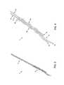
- FIGS. 1 and 2are schematic views showing how the novel suture assembly of the present invention is assembled
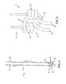
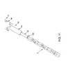
- FIGS. 3 and 4are schematic views showing the novel suture assembly of FIG. 2 in a longitudinally-expanded, radially-contracted first configuration for insertion into a bone hole;
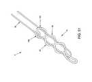
- FIGS. 5 and 6are schematic views showing the novel suture assembly of FIG. 2 in a longitudinally-contracted, radially-expanded second configuration for lodging in a bone hole;
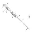
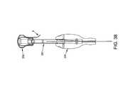
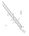
- FIG. 7is a schematic view showing an inserter assembly and associated cannulated drill guide assembly which may be used to deploy the novel suture assembly of FIG. 2 in a bone;
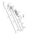
- FIGS. 8-11are schematic views showing various aspects of the inserter assembly and associated cannulated drill guide assembly of FIG. 7 , and showing the novel suture assembly of FIG. 2 in its longitudinally-expanded, radially-contracted first configuration and loaded in the inserter assembly;
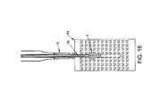
- FIGS. 12-18are schematic views showing one manner in which the inserter assembly and associated cannulated drill guide assembly of FIG. 7 can be used to deploy the novel suture assembly of FIG. 2 in a bone, with FIG. 18 showing the novel suture assembly released from the inserter assembly and in its longitudinally-contracted, radially-expanded second configuration so as to be secured to the bone;
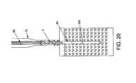
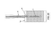
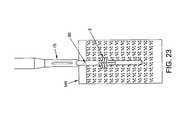
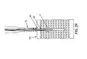
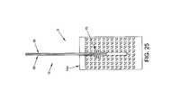
- FIGS. 19-26are schematic views showing another manner in which the inserter assembly and associated cannulated drill guide assembly of FIG. 7 can be used to deploy the novel suture assembly of FIG. 2 in a bone, with FIG. 26 showing the novel suture assembly released from the inserter assembly and in its longitudinally-contracted, radially-expanded second configuration so as to be secured to the bone;
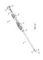
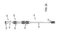
- FIGS. 27-31are schematic views showing another inserter assembly and associated cannulated drill guide assembly which may be used to deploy the novel suture assembly of FIG. 2 in a bone;
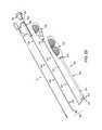
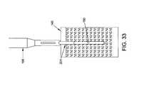
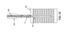
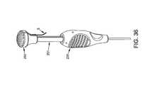
- FIGS. 32-49are schematic views showing the inserter assembly and associated cannulated drill guide assembly of FIGS. 27-31 deploying the novel suture assembly of FIG. 2 in a bone, with FIG. 49 showing the novel suture assembly released from the inserter assembly and in its longitudinally-contracted, radially-expanded second configuration so as to be secured to the bone;
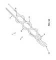
- FIGS. 50-54are schematic views showing alternative forms of the novel suture assembly of FIG. 2 .
- FIGS. 1 and 2there is shown a novel suture assembly 5 for securing suture to bone, such that the suture may be used to secure an object (e.g., soft tissue) to the bone.
- an objecte.g., soft tissue
- novel suture assembly 5generally comprises a first length of suture (“first suture”) 10 ( FIGS. 1 and 2 ) and a second length of suture (“second suture”) 15 ( FIG. 2 ).
- First suture 10comprises a first end 20 and second end 25 such that when first suture 10 is folded back on itself, it forms a first arm 30 which includes first end 20 , and a second arm 35 which includes second end 25 , with first arm 30 being connected to second arm 35 via a bridge 40 .
- Second suture 15comprises a first end 45 and second end 50 such that when second suture 15 is folded back on itself, it forms a first arm 55 which includes first end 45 , and a second arm 60 which includes second end 50 , with first arm 55 being connected to second arm 60 via a bridge 65 .
- Second suture 15is wrapped around first suture 10 by (i) folding second suture 15 back on itself so as to provide first arm 55 and second arm 60 , with first arm 55 being connected to second arm 60 via a bridge 65 ; (ii) positioning bridge 65 of second suture 15 across first arm 30 and second arm 35 of first suture 10 , with bridge 65 of second suture 15 being spaced from bridge 40 of first suture 10 ; and (iii) wrapping first arm 55 of second suture 15 around first arm 30 of first suture 10 , and wrapping second arm 60 of second suture 15 around second arm 35 of first suture 10 , in the manner shown in FIG. 2 .
- first arm 55 of second suture 15is wrapped around first arm 30 of first suture 10 in a first direction
- second arm 60 of second suture 15is wrapped around second arm 35 of first suture 10 in a second, opposite direction.
- first arm 55 of second suture 15is arranged in a first helical configuration about first arm 30 of first suture 10
- second arm 60 of second suture 15is arranged in a second, oppositely wound helical configuration about second arm 35 of first suture 10 .
- first arm 55 and second arm 65This opposite winding of first arm 55 and second arm 65 is a very significant aspect of the present invention, since it provides the novel suture assembly with a highly defined, appropriately shaped and consistently reproducible structure when the novel suture assembly is subsequently transformed from its longitudinally-expanded, radially-contracted first configuration into its longitudinally-contracted, radially-expanded second configuration, as will hereinafter be discussed in further detail.
- first arm 55 of second suture 15is wrapped three times around first arm 30 of first suture 10 in a clockwise direction (when viewed from the frame of reference of bridge 65 ), and second arm 60 of second suture 15 is wrapped three times around second arm 35 of first suture 10 in a countereclockwise direction (when viewed from the frame of reference of bridge 65 ), in the manner shown in FIG. 2 .
- first arm 55 of second suture 15is wrapped four times around first arm 30 of first suture 10 in a clockwise direction (when viewed from the frame of reference of bridge 65 ), and second arm 60 of second suture 15 is wrapped four times around second arm 35 of first suture 10 in a countereclockwise direction (when viewed from the frame of reference of bridge 65 ).
- first arm 55 of second suture 15is wrapped two times around first arm 30 of first suture 10 in a clockwise direction (when viewed from the frame of reference of bridge 65 ), and second arm 60 of second suture 15 is wrapped two times around second arm 35 of first suture 10 in a countereclockwise direction (when viewed from the frame of reference of bridge 65 ).
- novel suture assembly 5can assume a first configuration in which second suture 15 is wrapped loosely around first suture 10 , i.e., so that the suture assembly assumes a longitudinally-elongated, radially-contracted first configuration ( FIGS. 3 and 4 ) which is suitable for insertion into a hole formed in bone.
- suture assembly 5can be transformed from the aforementioned longitudinally-elongated, radially-contracted first configuration into a longitudinally-contracted, radially-expanded second configuration ( FIGS. 5 and 6 ) which is suitable for securing the suture assembly in the hole formed in bone.
- first arm 30 and second arm 35 of first suture 10will extend out of the hole formed in the bone and be available for securing an object (e.g., soft tissue) to the bone.
- objecte.g., soft tissue
- novel suture assembly 5in the manner previously described (e.g., by wrapping first arm 55 of second suture 15 around first arm 30 of first suture 10 , and by wrapping second arm 60 of second suture 15 around second arm 35 of first suture 10 , with first arm 55 and second arm 60 being wound in opposite directions on first arm 30 and second arm 35 , respectively), it is possible to form the highly defined, appropriately shaped structure shown in FIGS. 5 and 6 in a highly consistent manner when suture assembly 5 is transformed from its longitudinally-expanded, radially-contracted first configuration ( FIGS. 3 and 4 ) into its longitudinally-contracted, radially-expanded second configuration ( FIGS. 5 and 6 ).
- the highly defined, appropriately shaped and consistently reproducible structure shown in FIGS. 5 and 6is capable of carrying substantial loads without losing its defined shape when loads are applied to the first and second ends 20 , 25 of first suture 10 .
- novel suture assembly 5will provide an excellent suture anchor with high holding strength.
- the novel suture assembly 5by forming the novel suture assembly 5 in the manner previously described (e.g., by wrapping first arm 55 of second suture 15 around first arm 30 of first suture 10 , and by wrapping second arm 60 of second suture 15 around second arm 35 of first suture 10 , with first arm 55 and second arm 60 being wound in opposite directions on first arm 30 and second arm 35 , respectively), the novel suture assembly 5 does not form a knot in either its longitudinally-expanded, radially-contracted first configuration ( FIGS. 3 and 4 ) or its longitudinally-contracted, radially-expanded second configuration ( FIGS. 5 and 6 ). In either configuration, the novel suture assembly 5 may be disassembled by simply pulling first arm 30 of first suture 10 , or by pulling second arm 35 of first suture 10 , away from second suture 15 , whereby to “undo” the suture assembly.
- first suture 10comprises a first length of woven suture
- second suture 15comprises a second length of woven suture
- novel suture assembly 5constitutes an all-suture construct which can assume (i) a longitudinally-expanded, radially-contracted first configuration for insertion into a hole formed in a bone, and (ii) a longitudinally-contracted, radially-expanded second configuration for lodging in the hole formed in the bone, with the suture assembly providing a pair of free suture arms extending out of the hole formed in the bone for use in securing an object (e.g., soft tissue) to the bone.
- an objecte.g., soft tissue
- the longitudinally-contracted, radially-expanded second configuration of the suture assemblyconstitutes a highly defined, appropriately shaped and consistently reproducible structure which is able to carry substantial loads without losing its defined shape, whereby to provide a suture anchor with high holding strength.
- the novel suture assembly 5does not form a knot in either its longitudinally-expanded, radially-contracted first configuration ( FIGS. 3 and 4 ) or its longitudinally-contracted, radially-expanded second configuration ( FIGS. 5 and 6 ). In either configuration, the novel suture assembly 5 may be disassembled by simply pulling first arm 30 of first suture 10 , or by pulling second arm 35 of first suture 10 , away from second suture 15 , whereby to “undo” the suture assembly.
- Inserter assembly 70and associated cannulated drill guide assembly 75 which may be used to deploy novel suture assembly 5 in bone.
- Inserter assembly 70in turn comprises an insertion tube assembly 80 and a push rod assembly 85 .
- cannulated drill guide assembly 75generally comprises an elongated drill guide tube 86 having a distal end 90 carrying distal end prongs 95 , and a proximal end 100 carrying a drill guide handle 105 .
- a lumen 106extends through elongated drill guide tube 86 and drill guide handle 105 .
- Insertion tube assembly 80generally comprises an elongated insertion tube 107 having a distal end 110 sized to receive novel suture assembly 5 (either loosely or, more preferably, tightly compressed) when the novel suture assembly is in its aforementioned longitudinally-expanded, radially-contracted first configuration ( FIGS. 3, 4, 10 and 11 ).
- Elongated insertion tube 107 of insertion tube assembly 80also comprises a proximal end 115 carrying an insertion tube handle 120 .
- a lumen 121extends through elongated tube insertion 107 and insertion tube handle 120 .
- Push rod assembly 85generally comprises a push rod 122 having a distal end 125 terminating in a distal end surface 130 , and a proximal end 135 carrying a push rod handle 140 .
- Insertion tube assembly 80is sized so that its elongated insertion tube 107 can be received within lumen 106 of cannulated drill guide assembly 75 such that, when cannulated drill guide assembly 75 is used to form a hole in a bone, the distal end of insertion tube assembly 80 can be delivered to that hole in a bone, as will hereinafter be discussed.
- Push rod assembly 85is sized so that its push rod 122 can be slidably received within lumen 121 of insertion tube assembly 80 such that, when novel suture assembly 5 is disposed within the distal end 110 of elongated insertion tube 107 of insertion tube assembly 80 , advancement of push rod assembly 85 relative to insertion tube assembly 80 , and/or retraction of insertion tube assembly 80 while holding push rod assembly 85 stationary, will cause novel suture assembly 5 to be released from distal end 110 of elongated insertion tube 107 of insertion tube assembly 80 , as will hereinafter be discussed.
- novel suture assembly 5has been released from distal end 110 of elongated insertion tube 107 of insertion tube assembly 80 , tensioning first arm 30 and second arm 35 of first suture 10 , while push rod assembly 85 holds bridge 65 of second suture 15 from moving proximally, will cause novel suture assembly 5 to transform from its longitudinally-elongated, radially-contracted first configuration ( FIGS. 3, 4, 10 and 11 ) into its longitudinally-contracted, radially-expanded second configuration ( FIGS. 5 and 6 ).
- Insertion tube assembly 80is also sized so that its lumen 121 will accommodate first and second arms 30 , 35 of first suture 10 alongside push rod 122 of push rod assembly 85 when push rod 122 is disposed in lumen 121 of insertion tube assembly 80 .
- Novel suture assembly 5is intended to be disposed within the distal end of insertion tube assembly 80 , distal to push rod assembly 85 , with first arm 30 and second arm 35 of first suture 10 extending out the proximal end of inserter assembly 70 via lumen 121 of insertion tube assembly 80 , with first arm 30 and second arm 35 of first suture 10 extending alongside push rod 122 of push rod assembly 85 .
- Preferably novel suture assembly 5is tightly compressed within the distal end of insertion tube assembly 80 , so as to provide the largest possible differential between the diameter of the radially-elongated, radially-contracted first configuration ( FIGS. 3, 4, 10 and 11 ) and the longitudinally-contracted, radially-expanded second configuration ( FIGS.
- first and second sutures 10 , 15are wound in opposite directions on first arm 30 and second arm 35 , respectively, it is possible for the first and second sutures 10 , 15 to “self-accommodate” within the interior of insertion tube assembly 80 , thereby permitting maximum compression of the novel suture assembly within the insertion tube assembly.
- first and second sutures 10 , 15can further self-accommodate within the interior of insertion tube assembly 80 , thereby permitting maximum compression of the novel suture assembly within the insertion tube assembly.
- novel suture assembly 5in the specific manner discussed above, the suture assembly is capable of self-accommodating itself into the smallest possible diameter within the insertion tube assembly, thereby permitting maximum compression of the novel suture assembly within the insertion tube assembly, and hence permitting use of a smaller bone hole and thus providing maximum holding power within the bone.
- Novel suture assembly 5may be used to secure suture to bone, such that the suture may be used to secure an object (e.g., soft tissue) to the bone.
- objecte.g., soft tissue
- inserter assembly 70 and its associated cannulated drill guide assembly 75may be used to deploy novel suture assembly 5 in bone, in order to secure an object to bone.
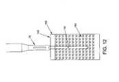
- cannulated drill guide assembly 75is first placed against the surface of a bone 145 ( FIG. 12 ) which is to have suture secured thereto.
- prongs 95 on the distal end of cannulated drill guide assembly 75help stabilize the cannulated drill guide assembly against the bone.
- a bone drill(not shown) of the sort well known in the art is advanced through lumen 106 of the cannulated drill guide assembly 75 and into the bone so that a bone hole 150 of appropriate size (diameter and depth) is formed in the bone.
- bone hole 150extends through the cortical layer 155 of bone 145 and into the cancellous region 160 of the bone.
- the bone drillis removed from cannulated drill guide assembly 75 while leaving the drill guide in position against bone 145 .
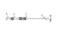
- the distal end 110 of insertion tube assembly 80carrying novel repair contruct 5 therein, is advanced through cannulated drill guide assembly 75 and into bone hole 150 formed in bone 145 ( FIGS. 13 and 14 ).
- push rod 122 of push rod assembly 85is already disposed within lumen 121 of insertion tube assembly 80 as this occurs, with distal end 130 of push rod assembly 85 sitting against bridge 65 of second suture 15 .
- push rod 122 of push rod assembly 85can be inserted into lumen 121 of insertion tube assembly 80 after the distal end of insertion tube assembly 80 has been inserted into bone hole 150 so that distal end 130 of push rod assembly 85 sits against bridge 65 of second suture 15 .
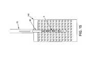
- insertion tube assembly 80is retracted while holding distal end 130 of push rod assembly 85 stationary, so that novel suture assembly 5 is released from the distal end 110 of insertion tube assembly 80 ( FIG. 15 ).
- first arm 30 and second arm 35 of first suture 10are tensioned, thereby transforming novel suture assembly 5 from its longitudinally-extended, radially-contracted first configuration into its longitudinally-contracted, radially-expanded second configuration ( FIG. 16 ), whereby to expand novel suture assembly 5 laterally into the cancellous region 160 of bone 145 .
- inserter assembly 70 and cannulated drill guide assembly 75are removed from the surgical site ( FIG. 17 ), and first arm 30 and second arm 35 of first suture 10 are tensioned further so as to further laterally expand novel suture assembly 5 and cause the laterally-expanded novel suture assembly to seat against the underside of cortical layer 155 of bone 145 ( FIG. 18 ), whereby to secure the novel suture assembly 5 within bone hole 150 ( FIG. 18 ), with first arm 30 and second arm 35 of first suture 10 extending out of the bone hole.
- novel suture assembly 5in the manner previously described (e.g., by wrapping first arm 55 of second suture 15 around first arm 30 of first suture 10 , and by wrapping second arm 60 of second suture 15 around second arm 35 of first suture 10 , with first arm 55 and second arm 60 being wound in opposite directions on first arm 30 and second arm 35 , respectively), it is possible to form the highly defined, appropriately shaped structure shown in FIGS. 5 and 6 in a highly consistent manner when suture assembly 5 is transformed from its longitudinally-expanded, radially-contracted first configuration ( FIGS. 3 and 4 ) into its longitudinally-contracted, radially-expanded second configuration ( FIGS. 5 and 6 ).
- the highly defined, appropriately shaped and consistently reproducible structure shown in FIGS. 5 and 6is capable of carrying substantial loads without losing its defined shape when loads are applied to the first and second ends 20 , 25 of first suture 10 .
- novel suture assembly 5will provide an excellent suture anchor with high holding strength.
- first arm 30 and second arm 35 of first suture 10may be used to secure an object (e.g., soft tissue) to the bone.
- an objecte.g., soft tissue
- first arm 30 and second arm 35may be passed through a piece of soft tissue (e.g., a ligament) and then tied together so as to secure the soft tissue to bone.
- the novel suture assembly 5does not form a knot in either its longitudinally-expanded, radially-contracted first configuration ( FIGS. 3 and 4 ) or its longitudinally-contracted, radially-expanded second configuration ( FIGS. 5 and 6 ).
- the novel suture assembly 5may be disassembled by simply pulling first arm 30 of first suture 10 , or by pulling second arm 35 of first suture 10 , away from second suture 15 , whereby to “undo” the suture assembly.
- first arm 30 of first suture 10 , or second arm 35 of first suture 10is simply pulled away from second suture 15 , whereby to “undo” the suture assembly.
- second suture 15may be extracted from bone hole 150 (e.g., with a narrow suture grasper) and removed from the surgical site.
- cannulated drill guide assembly 75is first placed against the surface of bone 145 , then a bone drill (not shown) is advanced through lumen 106 of the cannulated drill guide assembly 75 and into the bone so that a bone hole 150 of appropriate size (diameter and depth) is formed in the bone, then the bone drill is removed from cannulated drill guide assembly 75 while leaving the cannulated drill guide assembly in position against bone 145 , and then the distal end 110 of insertion tube assembly 80 , carrying novel suture assembly 5 therein, is advanced through cannulated drill guide assembly 75 and into bone hole 150 formed in bone 145 ( FIGS. 19 and 20 ).
- push rod 122 of push rod assembly 85is already disposed within lumen 121 of insertion tube assembly 80 as this occurs, with distal end 130 of push rod assembly 85 sitting against bridge 65 of second suture 15 .
- push rod 122 of push rod assembly 85can be inserted into lumen 121 of insertion tube assembly 80 after the distal end of insertion tube assembly 80 has been inserted into bone hole 150 so that distal end 130 of push rod assembly 85 sits against bridge 65 of second suture 15 .
- push rod assembly 85is advanced distally, against bridge 65 of second suture 15 , so that novel suture assembly 5 is ejected from the distal end 110 of insertion tube assembly 80 ( FIGS. 21 and 22 ).
- first arm 30 and second arm 35 of first suture 10are tensioned, thereby transforming novel suture assembly 5 from its longitudinally-extended, radially-contracted first configuration into its longitudinally-contracted, radially-expanded second configuration ( FIGS. 23 and 24 ), whereby to expand novel suture assembly 5 laterally into the cancellous region 160 of bone 145 .
- inserter assembly 70 and cannulated drill guide assembly 75are removed from the surgical site ( FIG. 25 ), and first arm 30 and second arm 35 of first suture 10 are tensioned further so as to further laterally expand novel suture assembly 5 and cause the laterally-expanded novel suture assembly to seat against the underside of cortical layer 155 of bone 145 ( FIG. 26 ), whereby to secure the novel suture assembly 5 within bone hole 150 ( FIG. 26 ), with first arm 30 and second arm 35 of first suture 10 extending out of the bone hole.
- FIGS. 5 and 6it is possible to form the highly defined, appropriately shaped structure shown in FIGS. 5 and 6 in a highly consistent manner when suture assembly 5 is transformed from its longitudinally-expanded, radially-contracted first configuration ( FIGS. 3 and 4 ) into its longitudinally-contracted, radially-expanded second configuration ( FIGS. 5 and 6 ).
- FIGS. 5 and 6the highly defined, appropriately shaped and consistently reproducible structure shown in FIGS. 5 and 6 is capable of carrying substantial loads without losing its defined shape when loads are applied to the first and second ends 20 , 25 of first suture 10 .
- novel suture assembly 5will provide an excellent suture anchor with high holding strength.
- a suture assembly 5 constructed as previously describedwas delivered into a 2 mm foam bone hole approximately 20-25 mm deep.
- the mediawas a 3 mm thick, 55-60 durometer foam bone layer over a 20 durometer foam bone block (Pacific Research Sawbones).
- the ultimate tensile strength of the suture assembly after insertion into foam bonewas approximately 77 pounds.
- the ultimate tensile strength for another suture assembly after insertion into a 1.5 mm foam bone holewas approximately 50 pounds.
- first arm 30 and second arm 35 of first suture 10may be used to secure an object (e.g., soft tissue) to the bone.
- objecte.g., soft tissue
- first arm 30 and second arm 35may be passed through a piece of soft tissue (e.g., a ligament) and then tied together so as to secure the soft tissue to the bone.
- novel suture assembly 5by forming the novel suture assembly 5 in the manner previously described (e.g., by wrapping first arm 55 of second suture 15 around first arm 30 of first suture 10 , and by wrapping second arm 60 of second suture 15 around second arm 35 of first suture 10 , with first arm 55 and second arm 60 being wound in opposite directions on first arm 30 and second arm 35 , respectively), the novel suture assembly 5 does not form a knot in either its longitudinally-expanded, radially-contracted first configuration ( FIGS. 3 and 4 ) or its longitudinally-contracted, radially-expanded second configuration ( FIGS. 5 and 6 ).
- the novel suture assembly 5may be disassembled by simply pulling first arm 30 of first suture 10 , or by pulling second arm 35 of first suture 10 , away from second suture 15 , whereby to “undo” the suture assembly.
- first arm 30 of first suture 10 , or second arm 35 of first suture 10is simply pulled away from second suture 15 , whereby to “undo” the suture assembly.
- second suture 15may be extracted from bone hole 150 (e.g., with a narrow suture grasper) and removed from the surgical site.
- the novel suture assembly of the present inventioncan be sized in accordance with a wide range of anatomical applications.
- the novel suture assemblycan be formed with relatively fine suture, and with a relatively small number of suture loops, so as to provide a relatively small structure for use with small and delicate anatomical structures.
- a novel suture assembly of this typecan be delivered through extremely small bone holes, e.g., on the order of 1 mm.
- the novel suture assemblycan be formed with relatively large suture, and with a relatively large number of suture loops, so as to provide a relatively large structure for use with robust anatomical structures.
- novel suture assembly 5in the manner previously described (e.g., by wrapping first arm 55 of second suture 15 around first arm 30 of first suture 10 , and by wrapping second arm 60 of second suture 15 around second arm 35 of first suture 10 , with first arm 55 and second arm 60 being wound in opposite directions on first arm 30 and second arm 35 , respectively), it is possible to form the highly defined, appropriately shaped structure shown in FIGS. 5 and 6 in a highly consistent manner when suture assembly 5 is transformed from its longitudinally-expanded, radially-contracted first configuration ( FIGS. 3 and 4 ) into its longitudinally-contracted, radially-expanded second configuration ( FIGS. 5 and 6 ).
- the suture assembly 5will provide an excellent suture anchor with high holding strength relative to its size (and relative to the size of the hole made in the host bone).
- novel suture assembly of the present inventioncan be used to attach objects to structures other than bone, e.g., the novel suture assembly can be used to attach skin to muscle.
- Inserter assembly 190and associated cannulated drill guide assembly 195 which may be used to deploy novel suture assembly 5 in bone.
- Inserter assembly 190in turn comprises an insertion tube assembly 200 and a push rod assembly 205 .
- drill guide assembly 195generally comprises an elongated drill guide tube 196 having a distal end 210 carrying distal end prongs 211 , and a proximal end 215 carrying a drill guide handle 220 .
- a lumen 221extends through elongated drill guide tube 196 and drill guide handle 220 .
- Insertion tube assembly 200generally comprises an elongated insertion tube 201 having a distal end 225 sized to receive novel suture assembly 5 (either loosely or, more preferably, tightly compressed) when the novel suture assembly is in its aforementioned longitudinally-extended, radially-contracted first configuration ( FIGS. 3 and 4 ).
- Elongated insertion tube 201 of insertion tube assembly 200also comprises a proximal end 230 carrying an insertion tube handle 235 .
- a lumen 231extends through elongated insertion tube 201 and insertion tube handle 235 .
- Push rod assembly 205generally comprises a push rod 236 having a distal end 240 terminating in a distal end surface 245 , and a proximal end 250 terminating in a push rod slide 251 .
- Push rod slide 251includes a suture slot 252 and suture saddle 253 which will hereinafter be discussed.
- a push rod handle 255is slidably mounted on push rod slide 251 so that the push rod handle is longitudinally movable relative to the push rod slide.
- a detent mechanismcomprising a radial projection 256 on push rod slide 251 , which engages a counterpart element 257 on push rod handle 255 , keeps push rod handle 255 in position on push rod slide 251 until a force of appropriate magnitude is applied to push rod handle 255 , whereupon push rod handle 255 will move relative to push rod slide 251 , as will hereinafter be discussed.
- Push rod handle 255includes an undersized slot 258 for releasably binding a suture to the push rod handle.
- Insertion tube assembly 200is sized so that its elongated insertion tube 201 can be received within lumen 221 of cannulated drill guide assembly 195 such that, when cannulated drill guide assembly 195 is used to form a hole in a bone, the distal end of insertion tube assembly 200 can be delivered to that hole in a bone, as will hereinafter be discussed.
- Push rod assembly 205is sized so that its push rod 236 can be slidably received within lumen 231 of insertion tube assembly 200 such that, when novel suture assembly 5 is disposed within the distal end 225 of elongated insertion tube 201 of insertion tube assembly 200 , advancement of push rod assembly 205 relative to insertion tube assembly 200 will cause novel suture assembly 5 to be ejected from distal end 225 of elongated insertion tube 201 of insertion tube assembly 200 , as will hereinafter be discussed.
- novel suture assembly 5has been ejected from distal end 225 of insertion tube 201 of insertion tube assembly 200 , tensioning first arm 30 and second arm 35 of first suture 10 , while push rod assembly 205 holds bridge 65 of second suture 15 from moving proximally, will cause novel suture assembly 5 to transform from its longitudinally-elongated, radially-contracted first configuration ( FIGS. 3 and 4 ) into its longitudinally-contracted, radially-expanded second configuration ( FIGS. 5 and 6 ).
- first arm 30 and second arm 35 of first suture 10is applied by moving push rod handle 255 longitudinally along push rod slide 251 (i.e., by applying a force of appropriate magnitude to the aforementioned detent mechanism), as will hereinafter be discussed.
- Insertion tube assembly 200is also sized so that its lumen 231 will accommodate first and second arms 30 , 35 of first suture 10 alongside push rod 236 of push rod assembly 205 when push rod 236 is disposed in lumen 231 of insertion tube assembly 200 .
- Novel suture assembly 5is intended to be disposed within the distal end of insertion tube assembly 200 , distal to push rod assembly 205 , with first arm 30 and second arm 35 of first suture 10 extending up lumen 231 of insertion tube assembly 200 (and alongside push rod 236 of push rod assembly 205 ), along suture slot 252 of push rod slide 251 , around suture saddle 253 of push rod slide 251 and then into undersized slot 258 of push rod handle 255 , whereby to releasably bind first and second arms 30 , 35 of first suture 10 to push rod handle 255 .
- novel suture assembly 5is tightly compressed within the distal end of insertion tube assembly 200 , so as to provide the largest possible differential between the diameter of the radially-elongated, radially-contracted first configuration ( FIGS. 3 and 4 ) and the longitudinally-contracted, radially-expanded second configuration ( FIGS. 5 and 6 ), whereby to minimize the size of the bone hole and thereby increase holding power in the bone.
- first and second sutures 10 , 15by winding first arm 55 of second suture 15 around first arm 30 of first suture 10 , and by wrapping second arm 60 of second suture 15 around second arm 35 of first suture 10 , with first arm 55 and second arm 60 being wound in opposite directions on first arm 30 and second arm 35 , respectively, it is possible for the first and second sutures 10 , 15 to “self-accommodate” within the interior of insertion tube assembly 200 , thereby permitting maximum compression of the novel suture assembly within the insertion tube.
- first and second sutures 10 , 15can further self-accommodate within the interior of insertion tube assembly 200 , thereby permitting maximum compression of the novel suture assembly within the insertion tube assembly.
- novel suture assembly 5in the specific manner discussed above, the suture assembly is capable of self-accommodating itself into the smallest possible diameter within the insertion tube assembly, thereby permitting maximum compression of the novel suture assembly within the insertion tube assembly, and hence permitting use of a smaller bone hole and thus providing maximum holding power within the bone.
- push rod handle 255is slidably mounted to push rod slide 251 using a detent mechanism, and the first arm 30 and second arm 35 of first suture 10 are releasably secured to push rod handle 255 after first passing over suture saddle 253 of push rod slide 251 , such that (i) by initially applying a force to push rod handle 255 which is below the trigger magnitude of the aforementioned detent mechanism, push rod handle 255 will initially cause push rod assembly 205 to be moved distally relative to insertion tube assembly 200 , whereby to eject suture assembly 205 from insertion tube assembly 200 , and (ii) by thereafter applying a force to push rod handle 255 which is above the trigger magnitude of the aforementioned detent mechanism, push rod handle 255 will thereafter move relative to push rod slide 251 , whereby to cause tension to be applied to first arm 30 and second arm 35 of first suture 10 without causing further distal motion of push rod 236 .
- novel suture assembly 5has been ejected from distal end 225 of insertion tube assembly 200 , first arm 30 and second arm 35 of first suture 10 are automatically tensioned, while push rod assembly 205 holds bridge 65 of second suture 15 from moving proximally, whereby to cause novel suture assembly 5 to transform from its longitudinally-elongated, radially-contracted first configuration ( FIGS. 3 and 4 ) into its longitudinally-contracted, radially-expanded second configuration ( FIGS. 5 and 6 ).
- novel suture assembly 5to first be ejected into a bone hole and then transformed from its longitudinally-elongated, radially-contracted first configuration into its longitudinally-contracted, radially-expanded second configuration.
- the alternative inserter assembly 190 shown in FIGS. 27-31 and its associated cannulated drill guide assembly 195may be used to deploy novel suture assembly 5 in bone, in order to secure an object to bone.
- cannulated drill guide assembly 195is first placed against the surface of bone 145 , then a bone drill (not shown) of the sort well known in the art is advanced through lumen 221 of the cannulated drill guide assembly and into the bone so that a bone hole 150 of appropriate size (diameter and depth) is formed in the bone, then the bone drill is removed from lumen 221 of cannulated drill guide assembly 195 while leaving the cannulated drill guide assembly in position against bone 145 , and then the distal end 225 of insertion tube assembly 200 , carrying novel repair contruct 5 therein, is advanced through cannulated drill guide assembly 195 and into bone hole 150 formed in bone 145 ( FIGS. 32-38 ). It will be appreciated that push rod 236 of push rod assembly 205 is already disposed within lumen 231 of insertion tube assembly 200 as this occurs, with distal end 240 of push rod assembly 205 sitting against bridge
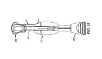
- push rod assembly 205is advanced distally, against bridge 65 of second suture 15 , so that novel suture assembly 5 is ejected from the distal end 225 of insertion tube assembly 200 ( FIGS. 39-43 ). This is done by pressing push rod handle 255 distally so that push rod assembly 205 advances distally relative to insertion tube 200 . As this occurs, push rod handle 255 remains fixed in position on push rod slide 251 due to the detent mechanism of radial projection 256 on push rod slide 251 and counterpart element 257 on push rod handle 255 . Push rod assembly 205 advances distally until push rod slide 251 bottoms out in its seat on insertion tube handle 235 ( FIG. 41 ).
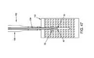
- first arm 30 and second arm 35 of first suture 10are tensioned, thereby transforming novel suture assembly 5 from its longitudinally-extended, radially-contracted first configuration into its longitudinally-contracted, radially-expanded second configuration ( FIGS. 44-47 ), whereby to expand novel suture assembly 5 laterally into the cancellous region 160 of bone 145 .
- Thisis done by pressing push rod handle 255 further distally so that push rod handle 255 overcomes the aforementioned detent mechanism with push rod slide 251 , thereby causing push rod handle 255 to move distally along push rod slide 251 , relative to insertion tube assembly 200 and push rod assembly 205 .
- the first and second arms 30 , 35 of first suture 10are tensioned, due to the increasing length of the suture path created around suture saddle 253 .
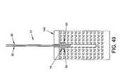
- first and second arms 30 , 35 of first suture 10are released from inserter assembly 190 (e.g., by dismounting the suture arms from undersized slot 258 of push rod handle 255 ), inserter assembly 190 is removed from the surgical site ( FIG. 48 ), and then first arm 30 and second arm 35 of first suture 10 are tensioned further so as to further laterally expand novel suture assembly 5 and cause the laterally-expanded novel suture assembly to seat against the underside of cortical layer 155 of bone 145 ( FIG. 49 ), whereby to secure the novel suture assembly 5 within bone hole 150 , with first arm 30 and second arm 35 of first suture 10 extending out of the bone hole.
- novel suture assembly 5in the manner previously described (e.g., by wrapping first arm 55 of second suture 15 around first arm 30 of first suture 10 , and by wrapping second arm 60 of second suture 15 around second arm 35 of first suture 10 , with first arm 55 and second arm 60 being wound in opposite directions on first arm 30 and second arm 35 , respectively), it is possible to form the highly defined, appropriately shaped structure shown in FIGS. 5 and 6 in a highly consistent manner when suture assembly 5 is transformed from its longitudinally-expanded, radially-contracted first configuration ( FIGS. 3 and 4 ) into its longitudinally-contracted, radially-expanded second configuration ( FIGS. 5 and 6 ).
- the highly defined, appropriately shaped and consistently reproducible structure shown in FIGS. 5 and 6is capable of carrying substantial loads without losing its defined shape when loads are applied to the first and second ends 20 , 25 of first suture 10 .
- novel suture assembly 5will provide an excellent suture anchor with high holding strength.
- first arm 30 and second arm 35 of first suture 10may be used to secure an object (e.g., soft tissue) to the bone.
- an objecte.g., soft tissue
- first arm 30 and second arm 35may be passed through a piece of soft tissue (e.g., a ligament) and then tied together so as to secure the soft tissue to bone.
- novel suture assembly 5by forming the novel suture assembly 5 in the manner previously described (e.g., by wrapping first arm 55 of second suture 15 around first arm 30 of first suture 10 , and by wrapping second arm 60 of second suture 15 around second arm 35 of first suture 10 , with first arm 55 and second arm 60 being wound in opposite directions on first arm 30 and second arm 35 , respectively), the novel suture assembly 5 does not form a knot in either its longitudinally-expanded, radially-contracted first configuration ( FIGS. 3 and 4 ) or its longitudinally-contracted, radially-expanded second configuration ( FIGS. 5 and 6 ).
- the novel suture assembly 5may be disassembled by simply pulling first arm 30 of first suture 10 , or by pulling second arm 35 of first suture 10 , away from second suture 15 , whereby to “undo” the suture assembly.
- first arm 30 of first suture 10 , or second arm 35 of first suture 10is simply pulled away from second suture 15 , whereby to “undo” the suture assembly.
- second suture 15may be extracted from bone hole 150 (e.g., with a narrow suture grasper) and removed from the surgical site.
- the novel suture assembly 5is a relatively flexible structure while it is in its aforementioned longitudinally-elongated, radially-contracted first configuration, it is capable of conforming to some extent to the geometry of the bone hole in which it is received as it is ejected from insertion tube assembly 200 and before it is transformed into its longitudinally-contracted, radially-expanded second configuration.
- the novel suture assembly 5can be deployed in relatively shallow bone holes, since it is relatively pliable when it is in its longitudinally-elongated, injection-state configuration and before it is transformed into its longitudinally-contracted, anchoring-state configuration.
- FIG. 2shows the preferred manner of forming novel suture assembly 5 .
- FIG. 50shows an alternative manner of forming novel suture assembly 5 .
- suture assembly 5is substantially the same as the suture assembly shown in FIG. 2 , except that two first sutures 10 , disposed in a parallel arrangement, are provided. This construction can be highly advantageous in some situations since it provides four strands of suture emerging from the bone hole.
- FIG. 51shows another manner of forming the novel suture construct 5 .
- second suture 15has an eyelet 180 formed on the end of first arm 55 and an eyelet 185 formed on the end of second arm 60 .
- First arm 55 of second suture 15is wrapped (e.g., three times) around first arm 30 of first suture 10 , with first arm 30 of first suture 10 passing through eyelet 180 of second suture 15
- second arm 60 of second suture 15is wrapped (e.g., three times) around second arm 35 of first suture 10 , with second arm 35 of first suture 10 passing through eyelet 185 of second suture 15 .
- first arm 55 of second suture 15is wrapped in the opposite direction from second arm 60 of second suture 15 .
- bridge 65 of second suture 15may be positioned close to, and extend substantially parallel to, bridge 40 of first suture 10 . While this form of the invention may permit enhanced compression of the novel suture assembly within the insertion tube, it is generally not preferred since it presents separate eyelets 180 , 185 to the distal end of the push rod assembly, rather than an integrated bridge 65 , and can be more difficult to reliably engage with the distal end of the push rod assembly.
- FIGS. 52-54Additional configurations are shown in FIGS. 52-54 . More particularly, the suture construct shown in FIG. 52 is substantially the same as the suture assembly shown in FIG. 2 , except that the first and second ends 45 , 50 of second suture 15 are joined together at 190 such that the second suture forms a substantially closed loop.
- Various meansmay be used to join together the first and second ends of second suture 15 , e.g., simply tying the ends into a knot (not shown); gluing or thermal welding, the use of a mechanical means or device such as a pledget that joins the ends together (not shown), etc.
- one end of second suture 15can be inserted through the body of the other end so as to form a single strand 195 ( FIG. 53 ).
- second suture 15can be manufactured as a closed loop, i.e., so as to provide a distal bridge 200 ( FIG. 54 ).
- FIGS. 52-54can work adequately in some situations, e.g., where a larger bone hole size is acceptable and lower holding strengths can be tolerated.
- the suture assemblies shown in FIGS. 52-54are not equivalent to the suture assembly shown in FIGS. 1-6 in either form or function. More particularly, with the suture assemblies shown in FIGS. 52-54 , second suture 15 effectively forms a substantially closed loop, whereas with the suture assembly of FIGS. 1-6 , the second suture 15 provides two free ends.
- the provision of two free ends with the suture assembly of FIGS. 1-6is a significant advantage over the suture assemblies shown in FIGS.
Landscapes
- Health & Medical Sciences (AREA)
- Surgery (AREA)
- Life Sciences & Earth Sciences (AREA)
- Medical Informatics (AREA)
- Animal Behavior & Ethology (AREA)
- Veterinary Medicine (AREA)
- Public Health (AREA)
- Engineering & Computer Science (AREA)
- Biomedical Technology (AREA)
- Heart & Thoracic Surgery (AREA)
- General Health & Medical Sciences (AREA)
- Molecular Biology (AREA)
- Nuclear Medicine, Radiotherapy & Molecular Imaging (AREA)
- Orthopedic Medicine & Surgery (AREA)
- Dentistry (AREA)
- Oral & Maxillofacial Surgery (AREA)
- Rheumatology (AREA)
- Neurology (AREA)
- Surgical Instruments (AREA)
- Apparatus For Radiation Diagnosis (AREA)
- Prostheses (AREA)
Abstract
Description
- a first suture having a generally U-shaped configuration comprising a first arm, a second arm and a bridge connecting the first arm to the second arm;
- a second suture comprising a first arm, a second arm and a bridge connecting the first arm to the second arm;
- the first arm of the second suture being wrapped around the first arm of the first suture in a first direction, and the second arm of the second suture being wrapped around the second arm of the first suture in a second, opposite direction;
- the suture assembly being capable of assuming (i) a longitudinally-extended, radially-contracted first configuration, and (ii) a longitudinally-contracted, radially-expanded second configuration;
- a first suture having a generally U-shaped configuration comprising a first arm, a second arm and a bridge connecting the first arm to the second arm;
- a second suture comprising a first arm, a second arm and a bridge connecting the first arm to the second arm;
- the first arm of the second suture being wrapped around the first arm of the first suture in a first direction, and the second arm of the second suture being wrapped around the second arm of the first suture in a second, opposite direction;
- the suture assembly being capable of assuming (i) a longitudinally-extended, radially-contracted first configuration, and (ii) a longitudinally-contracted, radially-expanded second configuration; and
- an insertion tube for carrying at least a portion of the suture assembly within the insertion tube when the suture assembly is in its longitudinally-extended, radially-contracted first configuration; and
- a push rod for engaging the suture assembly when the suture assembly is disposed within the insertion tube.
Claims (45)
Priority Applications (22)
| Application Number | Priority Date | Filing Date | Title |
|---|---|---|---|
| US13/093,634US9307977B2 (en) | 2010-11-04 | 2011-04-25 | Method and apparatus for securing an object to bone, including the provision and use of a novel suture assembly for securing suture to bone |
| JP2013537817AJP5922140B2 (en) | 2010-11-04 | 2011-11-03 | Method and apparatus for securing an object to a bone using a suture assembly |
| PCT/US2011/059126WO2012061586A1 (en) | 2010-11-04 | 2011-11-03 | Method and apparatus for securing an object to bone using a suture assembly |
| CN201180064121.7ACN103561671B (en) | 2010-11-04 | 2011-11-03 | For the method and apparatus using suture assembly to be fixed on bone by object |
| KR1020137014401AKR101900968B1 (en) | 2010-11-04 | 2011-11-03 | Method and apparatus for securing an object to bone using a suture assembly |
| AU2011323312AAU2011323312B2 (en) | 2010-11-04 | 2011-11-03 | Method and apparatus for securing an object to bone using a suture assembly |
| EP11838802.4AEP2654588B1 (en) | 2010-11-04 | 2011-11-03 | Apparatus for securing an object to bone using a suture assembly |
| ES11838802TES2939811T3 (en) | 2010-11-04 | 2011-11-03 | Apparatus for securing an object to bone using a suture set |
| CA2829769ACA2829769C (en) | 2010-11-04 | 2011-11-03 | Method and apparatus for securing an object to bone using a suture assembly |
| JP2013554612AJP5981459B2 (en) | 2011-02-16 | 2012-02-16 | Method and apparatus for bonding an object to bone, including the provision and use of a novel suture assembly for securing the object to bone |
| EP12746492.3AEP2675363B1 (en) | 2011-02-16 | 2012-02-16 | Apparatus for securing an object to bone |
| US13/398,589US9119893B2 (en) | 2010-11-04 | 2012-02-16 | Method and apparatus for securing an object to bone, including the provision and use of a novel suture assembly for securing an object to bone |
| KR1020137024256AKR102216856B1 (en) | 2011-02-16 | 2012-02-16 | Method and apparatus for securing an object to bone |
| CN201280018734.1ACN103648405B (en) | 2011-02-16 | 2012-02-16 | Method and apparatus for securing an object to a bone including providing and using a novel suture assembly to secure an object to a bone |
| AU2012217577AAU2012217577B2 (en) | 2011-02-16 | 2012-02-16 | Method and apparatus for securing an object to bone |
| CA2827494ACA2827494C (en) | 2011-02-16 | 2012-02-16 | Method and apparatus for securing an object to bone |
| KR1020197031627AKR102126423B1 (en) | 2011-02-16 | 2012-02-16 | Method and apparatus for securing an object to bone |
| PCT/US2012/025480WO2012112793A1 (en) | 2011-02-16 | 2012-02-16 | Method and apparatus for securing an object to bone |
| US13/559,047US9307978B2 (en) | 2010-11-04 | 2012-07-26 | Method and apparatus for securing an object to bone, including the provision and use of a novel suture assembly for securing an object to bone |
| US14/842,183US20160058435A1 (en) | 2010-11-04 | 2015-09-01 | Method and apparatus for securing an object to bone, including the provision and use of a novel suture assembly for securing an object to bone |
| US15/890,868US10888310B2 (en) | 2010-11-04 | 2018-02-07 | Method and apparatus for securing an object to bone, including the provision and use of a novel suture assembly for securing an object to bone |
| US17/144,351US12279762B2 (en) | 2010-11-04 | 2021-01-08 | Method and apparatus for securing an object to bone, including the provision and use of a novel suture assembly for securing an object to bone |
Applications Claiming Priority (5)
| Application Number | Priority Date | Filing Date | Title |
|---|---|---|---|
| US41002710P | 2010-11-04 | 2010-11-04 | |
| US41933410P | 2010-12-03 | 2010-12-03 | |
| US42285910P | 2010-12-14 | 2010-12-14 | |
| US201161443325P | 2011-02-16 | 2011-02-16 | |
| US13/093,634US9307977B2 (en) | 2010-11-04 | 2011-04-25 | Method and apparatus for securing an object to bone, including the provision and use of a novel suture assembly for securing suture to bone |
Related Parent Applications (1)
| Application Number | Title | Priority Date | Filing Date |
|---|---|---|---|
| US13/398,589Continuation-In-PartUS9119893B2 (en) | 2010-11-04 | 2012-02-16 | Method and apparatus for securing an object to bone, including the provision and use of a novel suture assembly for securing an object to bone |
Related Child Applications (2)
| Application Number | Title | Priority Date | Filing Date |
|---|---|---|---|
| US13/398,589Continuation-In-PartUS9119893B2 (en) | 2010-11-04 | 2012-02-16 | Method and apparatus for securing an object to bone, including the provision and use of a novel suture assembly for securing an object to bone |
| US13/559,047Continuation-In-PartUS9307978B2 (en) | 2010-11-04 | 2012-07-26 | Method and apparatus for securing an object to bone, including the provision and use of a novel suture assembly for securing an object to bone |
Publications (2)
| Publication Number | Publication Date |
|---|---|
| US20120116450A1 US20120116450A1 (en) | 2012-05-10 |
| US9307977B2true US9307977B2 (en) | 2016-04-12 |
Family
ID=46020346
Family Applications (1)
| Application Number | Title | Priority Date | Filing Date |
|---|---|---|---|
| US13/093,634Active2031-10-12US9307977B2 (en) | 2010-11-04 | 2011-04-25 | Method and apparatus for securing an object to bone, including the provision and use of a novel suture assembly for securing suture to bone |
Country Status (9)
| Country | Link |
|---|---|
| US (1) | US9307977B2 (en) |
| EP (1) | EP2654588B1 (en) |
| JP (1) | JP5922140B2 (en) |
| KR (1) | KR101900968B1 (en) |
| CN (1) | CN103561671B (en) |
| AU (1) | AU2011323312B2 (en) |
| CA (1) | CA2829769C (en) |
| ES (1) | ES2939811T3 (en) |
| WO (1) | WO2012061586A1 (en) |
Cited By (3)
| Publication number | Priority date | Publication date | Assignee | Title |
|---|---|---|---|---|
| US20190046178A1 (en)* | 2010-11-04 | 2019-02-14 | Conmed Corporation | Method and apparatus for securing an object to bone, including the provision and use of a novel suture assembly for securing an object to bone |
| US20230329696A1 (en)* | 2012-10-18 | 2023-10-19 | Smith & Nephew, Inc. | Flexible anchor delivery system |
| US11857176B2 (en) | 2011-01-28 | 2024-01-02 | Smith & Nephew, Inc. | Tissue repair |
Families Citing this family (65)
| Publication number | Priority date | Publication date | Assignee | Title |
|---|---|---|---|---|
| US7658751B2 (en) | 2006-09-29 | 2010-02-09 | Biomet Sports Medicine, Llc | Method for implanting soft tissue |
| US8303604B2 (en) | 2004-11-05 | 2012-11-06 | Biomet Sports Medicine, Llc | Soft tissue repair device and method |
| US8128658B2 (en) | 2004-11-05 | 2012-03-06 | Biomet Sports Medicine, Llc | Method and apparatus for coupling soft tissue to bone |
| US8088130B2 (en) | 2006-02-03 | 2012-01-03 | Biomet Sports Medicine, Llc | Method and apparatus for coupling soft tissue to a bone |
| US7905904B2 (en) | 2006-02-03 | 2011-03-15 | Biomet Sports Medicine, Llc | Soft tissue repair device and associated methods |
| US8137382B2 (en) | 2004-11-05 | 2012-03-20 | Biomet Sports Medicine, Llc | Method and apparatus for coupling anatomical features |
| US8361113B2 (en) | 2006-02-03 | 2013-01-29 | Biomet Sports Medicine, Llc | Method and apparatus for coupling soft tissue to a bone |
| US9017381B2 (en) | 2007-04-10 | 2015-04-28 | Biomet Sports Medicine, Llc | Adjustable knotless loops |
| US7749250B2 (en) | 2006-02-03 | 2010-07-06 | Biomet Sports Medicine, Llc | Soft tissue repair assembly and associated method |
| US8118836B2 (en) | 2004-11-05 | 2012-02-21 | Biomet Sports Medicine, Llc | Method and apparatus for coupling soft tissue to a bone |
| US8298262B2 (en) | 2006-02-03 | 2012-10-30 | Biomet Sports Medicine, Llc | Method for tissue fixation |
| US7909851B2 (en) | 2006-02-03 | 2011-03-22 | Biomet Sports Medicine, Llc | Soft tissue repair device and associated methods |
| US9801708B2 (en) | 2004-11-05 | 2017-10-31 | Biomet Sports Medicine, Llc | Method and apparatus for coupling soft tissue to a bone |
| US8840645B2 (en) | 2004-11-05 | 2014-09-23 | Biomet Sports Medicine, Llc | Method and apparatus for coupling soft tissue to a bone |
| US8998949B2 (en) | 2004-11-09 | 2015-04-07 | Biomet Sports Medicine, Llc | Soft tissue conduit device |
| US11259792B2 (en) | 2006-02-03 | 2022-03-01 | Biomet Sports Medicine, Llc | Method and apparatus for coupling anatomical features |
| US9149267B2 (en) | 2006-02-03 | 2015-10-06 | Biomet Sports Medicine, Llc | Method and apparatus for coupling soft tissue to a bone |
| US8771352B2 (en) | 2011-05-17 | 2014-07-08 | Biomet Sports Medicine, Llc | Method and apparatus for tibial fixation of an ACL graft |
| US8652171B2 (en) | 2006-02-03 | 2014-02-18 | Biomet Sports Medicine, Llc | Method and apparatus for soft tissue fixation |
| US8562645B2 (en) | 2006-09-29 | 2013-10-22 | Biomet Sports Medicine, Llc | Method and apparatus for forming a self-locking adjustable loop |
| US8652172B2 (en) | 2006-02-03 | 2014-02-18 | Biomet Sports Medicine, Llc | Flexible anchors for tissue fixation |
| US9538998B2 (en) | 2006-02-03 | 2017-01-10 | Biomet Sports Medicine, Llc | Method and apparatus for fracture fixation |
| US8968364B2 (en) | 2006-02-03 | 2015-03-03 | Biomet Sports Medicine, Llc | Method and apparatus for fixation of an ACL graft |
| US8597327B2 (en) | 2006-02-03 | 2013-12-03 | Biomet Manufacturing, Llc | Method and apparatus for sternal closure |
| US8574235B2 (en) | 2006-02-03 | 2013-11-05 | Biomet Sports Medicine, Llc | Method for trochanteric reattachment |
| US9271713B2 (en) | 2006-02-03 | 2016-03-01 | Biomet Sports Medicine, Llc | Method and apparatus for tensioning a suture |
| US8506597B2 (en) | 2011-10-25 | 2013-08-13 | Biomet Sports Medicine, Llc | Method and apparatus for interosseous membrane reconstruction |
| US10517587B2 (en) | 2006-02-03 | 2019-12-31 | Biomet Sports Medicine, Llc | Method and apparatus for forming a self-locking adjustable loop |
| US8562647B2 (en) | 2006-09-29 | 2013-10-22 | Biomet Sports Medicine, Llc | Method and apparatus for securing soft tissue to bone |
| US9468433B2 (en) | 2006-02-03 | 2016-10-18 | Biomet Sports Medicine, Llc | Method and apparatus for forming a self-locking adjustable loop |
| US9078644B2 (en) | 2006-09-29 | 2015-07-14 | Biomet Sports Medicine, Llc | Fracture fixation device |
| US8801783B2 (en) | 2006-09-29 | 2014-08-12 | Biomet Sports Medicine, Llc | Prosthetic ligament system for knee joint |
| US11311287B2 (en) | 2006-02-03 | 2022-04-26 | Biomet Sports Medicine, Llc | Method for tissue fixation |
| US11259794B2 (en) | 2006-09-29 | 2022-03-01 | Biomet Sports Medicine, Llc | Method for implanting soft tissue |
| US8672969B2 (en) | 2006-09-29 | 2014-03-18 | Biomet Sports Medicine, Llc | Fracture fixation device |
| US9918826B2 (en) | 2006-09-29 | 2018-03-20 | Biomet Sports Medicine, Llc | Scaffold for spring ligament repair |
| US8500818B2 (en) | 2006-09-29 | 2013-08-06 | Biomet Manufacturing, Llc | Knee prosthesis assembly with ligament link |
| US12419632B2 (en) | 2008-08-22 | 2025-09-23 | Biomet Sports Medicine, Llc | Method and apparatus for coupling anatomical features |
| US12245759B2 (en) | 2008-08-22 | 2025-03-11 | Biomet Sports Medicine, Llc | Method and apparatus for coupling soft tissue to bone |
| US8343227B2 (en) | 2009-05-28 | 2013-01-01 | Biomet Manufacturing Corp. | Knee prosthesis assembly with ligament link |
| US12096928B2 (en) | 2009-05-29 | 2024-09-24 | Biomet Sports Medicine, Llc | Method and apparatus for coupling soft tissue to a bone |
| US12329373B2 (en) | 2011-05-02 | 2025-06-17 | Biomet Sports Medicine, Llc | Method and apparatus for soft tissue fixation |
| JP6045582B2 (en)* | 2011-07-26 | 2016-12-14 | リンバテック・コーポレーション | Method and apparatus for securing an object to bone, including the provision and use of a novel suture assembly for securing an object to bone |
| US9357991B2 (en) | 2011-11-03 | 2016-06-07 | Biomet Sports Medicine, Llc | Method and apparatus for stitching tendons |
| US9381013B2 (en) | 2011-11-10 | 2016-07-05 | Biomet Sports Medicine, Llc | Method for coupling soft tissue to a bone |
| US9370350B2 (en) | 2011-11-10 | 2016-06-21 | Biomet Sports Medicine, Llc | Apparatus for coupling soft tissue to a bone |
| US9314241B2 (en) | 2011-11-10 | 2016-04-19 | Biomet Sports Medicine, Llc | Apparatus for coupling soft tissue to a bone |
| US9084597B2 (en) | 2012-03-09 | 2015-07-21 | Smith & Nephew, Inc. | Suture-based knotless repair |
| WO2014078754A1 (en)* | 2012-11-19 | 2014-05-22 | Covidien Lp | Tissue fixation device |
| US9795426B2 (en) | 2013-03-07 | 2017-10-24 | DePuy Synthes Products, Inc. | Implants |
| US9757119B2 (en) | 2013-03-08 | 2017-09-12 | Biomet Sports Medicine, Llc | Visual aid for identifying suture limbs arthroscopically |
| US9918827B2 (en) | 2013-03-14 | 2018-03-20 | Biomet Sports Medicine, Llc | Scaffold for spring ligament repair |
| US10136886B2 (en) | 2013-12-20 | 2018-11-27 | Biomet Sports Medicine, Llc | Knotless soft tissue devices and techniques |
| US9717491B2 (en)* | 2014-03-10 | 2017-08-01 | Biomet Sports Medicine, Llc | Method and apparatus for coupling soft tissue to bone |
| US9615822B2 (en) | 2014-05-30 | 2017-04-11 | Biomet Sports Medicine, Llc | Insertion tools and method for soft anchor |
| US9700291B2 (en) | 2014-06-03 | 2017-07-11 | Biomet Sports Medicine, Llc | Capsule retractor |
| US10039543B2 (en) | 2014-08-22 | 2018-08-07 | Biomet Sports Medicine, Llc | Non-sliding soft anchor |
| US9955980B2 (en) | 2015-02-24 | 2018-05-01 | Biomet Sports Medicine, Llc | Anatomic soft tissue repair |
| US9974534B2 (en) | 2015-03-31 | 2018-05-22 | Biomet Sports Medicine, Llc | Suture anchor with soft anchor of electrospun fibers |
| US9888997B2 (en) | 2015-07-20 | 2018-02-13 | Arthrex, Inc. | Soft anchor assembly with barbed flexible strand and techniques for use |
| US10307154B2 (en) | 2016-09-27 | 2019-06-04 | Arthrex, Inc. | Circular suture constructs and methods for use |
| CN107348978A (en)* | 2017-07-07 | 2017-11-17 | 上海利格泰生物科技有限公司 | Full suture holdfast and implanted mechanism |
| KR102117032B1 (en)* | 2018-08-27 | 2020-06-02 | 배석일 | Bone insertion device of soft suture anchor |
| CN111214265B (en)* | 2020-03-11 | 2024-12-27 | 上海利格泰生物科技股份有限公司 | Full-sewing fixing device with double-line structure, use method and rivet with line |
| US12433738B2 (en)* | 2021-03-22 | 2025-10-07 | Drew Miller | Tendon surgery nail knot systems and methods |
Citations (116)
| Publication number | Priority date | Publication date | Assignee | Title |
|---|---|---|---|---|
| US2012776A (en) | 1931-05-23 | 1935-08-27 | Roeder Hans Albert | Ligator |
| US3580256A (en) | 1969-06-30 | 1971-05-25 | Jack E Wilkinson | Pre-tied suture and method of suturing |
| JPS5594247U (en) | 1978-12-23 | 1980-06-30 | ||
| DE2900265A1 (en) | 1979-01-04 | 1980-07-17 | Fritz Dr Sammer | Surgical probe loop - has loop filament wound into self-locking coils (OE 15.8.79) |
| EP0246836B1 (en) | 1986-05-19 | 1991-12-18 | Cook Incorporated | Visceral anchor |
| WO1992011810A1 (en) | 1991-01-07 | 1992-07-23 | Laparomed Corporation | Device and method for applying suture |
| JPH0516155Y2 (en) | 1988-08-01 | 1993-04-27 | ||
| US5217470A (en) | 1991-04-29 | 1993-06-08 | Weston Peter V | Apparatuses and methods for formation and use of a slipknot as a surgical suture knot |
| DE4207854A1 (en) | 1992-03-12 | 1993-09-16 | Klemm Bernd | Preformed surgical thread for easy knotting - thread has elastic section with preformed loops in opposite-handed pairs part of length or end of thread is passed through loop to form knot |
| JPH0624533Y2 (en) | 1987-01-19 | 1994-06-29 | ニツコ−金属工業株式会社 | Push button type lock |
| US5405352A (en) | 1991-04-09 | 1995-04-11 | Weston; Peter V. | Suture knot, method for its formation and use, and knot forming apparatus |
| WO1995022932A1 (en) | 1994-02-23 | 1995-08-31 | Innovasive Devices, Inc. | Surgical grasping and suturing device |
| US5449367A (en) | 1993-08-02 | 1995-09-12 | Kadry; Othman | Pre-tied knot for surgical use and method of using same |
| JPH07328020A (en) | 1994-06-07 | 1995-12-19 | Matsutani Seisakusho Co Ltd | Medical threader and threaded needle used in the medical threader |
| US5549630A (en) | 1993-05-14 | 1996-08-27 | Bonutti; Peter M. | Method and apparatus for anchoring a suture |
| US5665111A (en) | 1996-01-22 | 1997-09-09 | Raymedica, Inc. | Method for anchoring a surgical suture to bone |
| US5665110A (en) | 1995-09-21 | 1997-09-09 | Medicinelodge, Inc. | Suture anchor system and method |
| US5718717A (en) | 1996-08-19 | 1998-02-17 | Bonutti; Peter M. | Suture anchor |
| US5728114A (en) | 1994-08-24 | 1998-03-17 | Kensey Nash Corporation | Apparatus and methods of use for preventing blood seepage at a percutaneous puncture site |
| US5893592A (en) | 1997-04-08 | 1999-04-13 | Ethicon Endo-Surgery, Inc. | Partially tied surgical knot |
| US5928244A (en) | 1996-10-04 | 1999-07-27 | United States Surgical Corporation | Tissue fastener implantation apparatus and method |
| US5989252A (en) | 1997-02-28 | 1999-11-23 | Fumex; Laurent | Surgical device for anchoring in bone, and ancillary for inserting it |
| US6086604A (en) | 1994-02-25 | 2000-07-11 | Fischell; Robert E. | Stent having a multiplicity of undulating longitudinals |
| US6110183A (en) | 1998-12-22 | 2000-08-29 | Cook Incorporated | Suture anchor device |
| US6113611A (en) | 1998-05-28 | 2000-09-05 | Advanced Vascular Technologies, Llc | Surgical fastener and delivery system |
| US6143006A (en) | 1998-04-18 | 2000-11-07 | Chan; Kwan-Ho | Apparatus and method for tying and tensioning knots |
| USRE36974E (en) | 1993-05-14 | 2000-11-28 | Bonutti; Peter M. | Suture anchor |
| US6179860B1 (en) | 1998-08-19 | 2001-01-30 | Artemis Medical, Inc. | Target tissue localization device and method |
| US6203572B1 (en) | 1999-02-09 | 2001-03-20 | Linvatec Corporation | Device and method for ligament reconstruction |
| CN1378439A (en) | 1999-10-18 | 2002-11-06 | 腱技术有限公司 | Apparatus and methods for tendon or ligament repair |
| US6500184B1 (en)* | 2001-01-31 | 2002-12-31 | Yung C. Chan | Suturing apparatus and method of suturing |
| US6503267B2 (en) | 1990-06-28 | 2003-01-07 | Peter M. Bonutti | Surgical devices assembled using heat bondable materials |
| US6511498B1 (en) | 1998-02-06 | 2003-01-28 | Laurent Fumex | Surgical bone anchoring device |
| US6524317B1 (en) | 1999-12-30 | 2003-02-25 | Opus Medical, Inc. | Method and apparatus for attaching connective tissues to bone using a knotless suture anchoring device |
| US6558396B1 (en) | 1999-05-06 | 2003-05-06 | Kanji Inoue | Apparatus for folding instrument and use of the same apparatus |
| WO2003065903A1 (en) | 2002-02-04 | 2003-08-14 | Jiro Kanie | Suture insrument for biological use |
| US20030167071A1 (en) | 2002-03-01 | 2003-09-04 | Evalve, Inc. | Suture fasteners and methods of use |
| US20030191497A1 (en) | 2002-04-05 | 2003-10-09 | Cook Incorporated | Sliding suture anchor |
| WO2003096910A1 (en) | 2002-05-17 | 2003-11-27 | Ucl Biomedica Plc | A device for transfixing and joining tissue |
| WO2004006782A1 (en) | 2002-07-10 | 2004-01-22 | Canica Design, Inc. | System and method for moving and stretching plastic tissue |
| US20040039442A1 (en) | 1999-04-09 | 2004-02-26 | Evalve, Inc. | Methods and apparatus for cardiac valve repair |
| US6712849B2 (en) | 2001-10-01 | 2004-03-30 | Scandius Biomedical, Inc. | Apparatus and method for reconstructing a ligament |
| US20040098050A1 (en) | 2002-11-19 | 2004-05-20 | Opus Medical, Inc. | Devices and methods for repairing soft tissue |
| EP1334702B1 (en) | 2002-02-08 | 2004-07-07 | Karl Storz GmbH & Co. KG | Anchor element to anchor a ligament transplant |
| US6767037B2 (en) | 2001-09-27 | 2004-07-27 | Depuy Mitek, Inc. | Sliding and locking surgical knot |
| US20040167546A1 (en) | 2002-12-11 | 2004-08-26 | Vahid Saadat | Methods for reduction of a gastric lumen |
| US20050187577A1 (en) | 2004-02-24 | 2005-08-25 | David Selvitelli | Methods and devices for repairing tissue |
| WO2005011463A3 (en) | 2003-07-01 | 2005-09-22 | Usgi Medical Inc | Methods and apparatus for gastric reduction |
| EP1495725B1 (en) | 2003-07-08 | 2005-09-28 | A- Spine Holding Group Corp. | Suture anchor and system for anchoring tissue to bone |
| US20050228448A1 (en) | 2004-03-18 | 2005-10-13 | Li Lehmann K | Suture anchoring system and method |
| US20050251202A1 (en) | 2004-05-07 | 2005-11-10 | Usgi Medical Inc. | Interlocking tissue anchor apparatus and methods |
| US20050251206A1 (en) | 2004-05-07 | 2005-11-10 | Usgi Medical Corporation | Apparatus and methods for positioning and securing anchors |
| US20050251209A1 (en) | 2004-05-07 | 2005-11-10 | Usgi Medical Inc. | Apparatus and methods for positioning and securing anchors |
| US20050251159A1 (en) | 2004-05-07 | 2005-11-10 | Usgi Medical Inc. | Methods and apparatus for grasping and cinching tissue anchors |
| US20050251210A1 (en) | 2004-05-07 | 2005-11-10 | Usgi Medical Inc. | Methods and apparatus for grasping and cinching tissue anchors |
| US6972027B2 (en) | 2002-06-26 | 2005-12-06 | Stryker Endoscopy | Soft tissue repair system |
| US20050277981A1 (en) | 2004-06-09 | 2005-12-15 | Usgi Medical Inc. | Apparatus and methods for optimizing anchoring force |
| US20050277985A1 (en) | 2004-06-14 | 2005-12-15 | Wert Zachary D | High-strength suture |
| US20050283192A1 (en) | 1999-12-02 | 2005-12-22 | Torrie Paul A | Closure device and method for tissue repair |
| JP2006025932A (en) | 2004-07-13 | 2006-02-02 | Jms Co Ltd | Biological suture tool and biological suture method |
| JP2006025934A (en) | 2004-07-13 | 2006-02-02 | Jms Co Ltd | Biological suture tool |
| JP2006025933A (en) | 2004-07-13 | 2006-02-02 | Jms Co Ltd | Biological suture tool |
| WO2006037639A1 (en) | 2004-10-06 | 2006-04-13 | Sherwood Services Ag | Organ fixing equipment and organ fixing equipment set |
| WO2006082810A1 (en) | 2005-02-04 | 2006-08-10 | Olympus Corporation | Medical suture ligation device and medical suture ligation tool |
| US20060190042A1 (en) | 2004-11-05 | 2006-08-24 | Arthrotek, Inc. | Tissue repair assembly |
| US20060212055A1 (en) | 2005-01-25 | 2006-09-21 | Karabey Halil I | Expandable occlusive structure |
| WO2007005394A1 (en) | 2005-07-05 | 2007-01-11 | Mitralign, Inc. | Tissue anchor and methods of using the same |
| WO2006111394A3 (en) | 2005-04-21 | 2007-04-05 | Sherwood Serv Ag | Surgical fastener, surgical fastener kit and removing tool |
| US20070083236A1 (en) | 2005-06-24 | 2007-04-12 | Smith & Nephew, Inc. | Methods and devices for tissue repair |
| US20070162120A1 (en) | 2005-12-26 | 2007-07-12 | Bernard Bouffier | Surgical device forming a surgical prosthesis |
| US20070185532A1 (en) | 2006-02-03 | 2007-08-09 | Arthrotek, Inc. | Soft tissue repair assembly and associated method |
| EP1832246A1 (en) | 2006-03-08 | 2007-09-12 | Arthrex, Inc. | Bundle graft and method of making same |
| US20070276433A1 (en) | 2006-05-23 | 2007-11-29 | St. Jude Medical Puerto Rico B.V. | Puncture closure apparatuses, sealing plugs, and related methods |
| US7303575B2 (en) | 2002-08-01 | 2007-12-04 | Lumen Biomedical, Inc. | Embolism protection devices |
| US20080009888A1 (en) | 2006-07-07 | 2008-01-10 | Usgi Medical, Inc. | Low profile tissue anchors, tissue anchor systems, and methods for their delivery and use |
| US20080015636A1 (en) | 2006-06-09 | 2008-01-17 | Daniel Olsen | Single disc intraluminal patent foramen ovale closure device |
| US20080015635A1 (en) | 2006-06-09 | 2008-01-17 | Daniel Olsen | Single disc occlusionary patent foramen ovale closure device |
| US20080027446A1 (en) | 2006-02-03 | 2008-01-31 | Biomet Sports Medicine, Inc. | Soft Tissue Repair and Conduit Device |
| US20080033487A1 (en) | 2006-08-07 | 2008-02-07 | Bioduct, Llc | Medical device for repair of tissue and method for implantation and fixation |
| US7329279B2 (en) | 2003-12-23 | 2008-02-12 | Sadra Medical, Inc. | Methods and apparatus for endovascularly replacing a patient's heart valve |
| WO2008010738A8 (en) | 2007-01-24 | 2008-02-28 | Uros Babic | Patent foramen ovale occluder with suture based anchor |
| US7347863B2 (en) | 2004-05-07 | 2008-03-25 | Usgi Medical, Inc. | Apparatus and methods for manipulating and securing tissue |
| US20080082128A1 (en) | 2006-09-29 | 2008-04-03 | Arthrotek, Inc. | Method and apparatus for forming a self-locking adjustable suture loop |
| US20080097522A1 (en) | 2003-08-07 | 2008-04-24 | Boston Scientific Scimed, Inc. | Medical closure device |
| WO2008048667A1 (en) | 2006-10-20 | 2008-04-24 | St. Jude Medical, Cardiology Division, Inc. | Knot pusher device |
| US20080140092A1 (en) | 2006-02-03 | 2008-06-12 | Stone Kevin T | Soft tissue repair device and associated methods |
| US20080140093A1 (en) | 2006-02-03 | 2008-06-12 | Stone Kevin T | Soft tissue repair device and associated methods |
| US20080147102A1 (en) | 2006-12-15 | 2008-06-19 | Rotella John A | Segmented tissue-to-tissue anchoring device and method of using the same |
| US20080147086A1 (en) | 2006-10-05 | 2008-06-19 | Marcus Pfister | Integrating 3D images into interventional procedures |
| US20080167658A1 (en) | 2006-12-19 | 2008-07-10 | Sean Kerr | Injectable fastener system and method |
| US20080177302A1 (en) | 2007-01-17 | 2008-07-24 | Shurnas Paul J | Lisfranc repair using suture-button construct |
| US20080200930A1 (en) | 2004-05-07 | 2008-08-21 | Usgi Medical, Inc. | Apparatus for manipulating and securing tissue |
| US20080208225A1 (en) | 2002-07-31 | 2008-08-28 | Abbott Laboratories Vascular Enterprises, Ltd. | Apparatus for sealing surgical punctures |
| US20080228265A1 (en) | 2007-03-13 | 2008-09-18 | Mitralign, Inc. | Tissue anchors, systems and methods, and devices |
| US20080228198A1 (en) | 2007-03-13 | 2008-09-18 | Mitralign, Inc. | Suture cutter and method of cutting suture |
| US20080228267A1 (en) | 2003-12-23 | 2008-09-18 | Mitralign, Inc. | Devices and methods for introducing elements into tissue |
| US20080255613A1 (en) | 2007-04-10 | 2008-10-16 | Biomet Sports Medicine, Inc. | Adjustable knotless loops |
| US20080281355A1 (en) | 2005-05-04 | 2008-11-13 | Etech Ag | Joining Element |
| US20080312689A1 (en) | 2004-11-05 | 2008-12-18 | Biomet Sports Medicine, Llc | Method and apparatus for coupling sof tissue to a bone |
| US20080319524A1 (en) | 2005-09-06 | 2008-12-25 | Allium Ltd. | System and Method for Delivering a Medical Device to a Body Location |
| US7491212B2 (en) | 2003-02-19 | 2009-02-17 | Smith & Nephew, Inc. | Transmitting an actuating force along a curved instrument |
| JP4226643B2 (en) | 2005-11-15 | 2009-02-18 | アップサイド株式会社 | Straining body, capacitive force sensor and capacitive acceleration sensor |
| US7494496B2 (en) | 2002-05-17 | 2009-02-24 | Ucl Biomedica Plc | Device for transfixing and joining tissue |
| US20090062854A1 (en) | 2004-11-05 | 2009-03-05 | Biomet Sports Medicine, Llc | Method and apparatus for coupling soft tissue to bone |
| US20090062848A1 (en) | 2007-08-31 | 2009-03-05 | Ken Christopher G M | Closure medical device |
| US20090082805A1 (en) | 2006-09-29 | 2009-03-26 | Biomet Sports Medicine, Llc | Adjustable knotless loops |
| US20090182335A1 (en) | 2007-11-05 | 2009-07-16 | Steven Struhl | Device for treatment of acromioclavicular joint dislocations |
| US7594929B2 (en) | 2002-11-21 | 2009-09-29 | Michel Collette | Anchoring screw for a relay strip or suture |
| US20090312776A1 (en) | 2006-02-03 | 2009-12-17 | Biomet Sports Medicine, Llc | Method and Apparatus for Coupling Soft Tissue to a Bone |
| US20090318961A1 (en)* | 2006-02-03 | 2009-12-24 | Biomet Sports Medicine,Llc | Method and Apparatus for Coupling Soft Tissue to a Bone |
| US20100204730A1 (en) | 2008-10-09 | 2010-08-12 | Nicholas Maiorino | Knotted Suture End Effector |
| WO2010105046A1 (en) | 2009-03-11 | 2010-09-16 | Synthes Usa, Llc | Threadable knot soft tissue defect repair system |
| EP2277457A1 (en) | 2009-07-24 | 2011-01-26 | DePuy Mitek, Inc. | Devices for repairing and anchoring damaged tissue |
| US20110022084A1 (en) | 2009-07-24 | 2011-01-27 | Mehmet Ziya Sengun | Methods and devices for repairing and anchoring damaged tissue |
| US20110098727A1 (en) | 2006-09-29 | 2011-04-28 | Biomet Sports Medicine, Llc | Method and Apparatus for Securing Soft Tissue to Bone |
| WO2011137159A1 (en) | 2010-04-27 | 2011-11-03 | Synthes Usa, Llc | Anchor assembly including expandable anchor |
- 2011
- 2011-04-25USUS13/093,634patent/US9307977B2/enactiveActive
- 2011-11-03KRKR1020137014401Apatent/KR101900968B1/enactiveActive
- 2011-11-03CNCN201180064121.7Apatent/CN103561671B/enactiveActive
- 2011-11-03ESES11838802Tpatent/ES2939811T3/enactiveActive
- 2011-11-03CACA2829769Apatent/CA2829769C/enactiveActive
- 2011-11-03AUAU2011323312Apatent/AU2011323312B2/enactiveActive
- 2011-11-03JPJP2013537817Apatent/JP5922140B2/enactiveActive
- 2011-11-03WOPCT/US2011/059126patent/WO2012061586A1/enactiveApplication Filing
- 2011-11-03EPEP11838802.4Apatent/EP2654588B1/enactiveActive
Patent Citations (162)
| Publication number | Priority date | Publication date | Assignee | Title |
|---|---|---|---|---|
| US2012776A (en) | 1931-05-23 | 1935-08-27 | Roeder Hans Albert | Ligator |
| US3580256A (en) | 1969-06-30 | 1971-05-25 | Jack E Wilkinson | Pre-tied suture and method of suturing |
| JPS5594247U (en) | 1978-12-23 | 1980-06-30 | ||
| DE2900265A1 (en) | 1979-01-04 | 1980-07-17 | Fritz Dr Sammer | Surgical probe loop - has loop filament wound into self-locking coils (OE 15.8.79) |
| EP0246836B1 (en) | 1986-05-19 | 1991-12-18 | Cook Incorporated | Visceral anchor |
| JPH0624533Y2 (en) | 1987-01-19 | 1994-06-29 | ニツコ−金属工業株式会社 | Push button type lock |
| JPH0516155Y2 (en) | 1988-08-01 | 1993-04-27 | ||
| US6503267B2 (en) | 1990-06-28 | 2003-01-07 | Peter M. Bonutti | Surgical devices assembled using heat bondable materials |
| WO1992011810A1 (en) | 1991-01-07 | 1992-07-23 | Laparomed Corporation | Device and method for applying suture |
| US5405352A (en) | 1991-04-09 | 1995-04-11 | Weston; Peter V. | Suture knot, method for its formation and use, and knot forming apparatus |
| US5217470A (en) | 1991-04-29 | 1993-06-08 | Weston Peter V | Apparatuses and methods for formation and use of a slipknot as a surgical suture knot |
| DE4207854A1 (en) | 1992-03-12 | 1993-09-16 | Klemm Bernd | Preformed surgical thread for easy knotting - thread has elastic section with preformed loops in opposite-handed pairs part of length or end of thread is passed through loop to form knot |
| US6287325B1 (en) | 1993-05-14 | 2001-09-11 | Peter M. Bonutti | Method and apparatus for anchoring a suture |
| US5733306A (en) | 1993-05-14 | 1998-03-31 | Bonutti; Peter M. | Method and apparatus for anchoring a suture |
| US5549630A (en) | 1993-05-14 | 1996-08-27 | Bonutti; Peter M. | Method and apparatus for anchoring a suture |
| US5584862A (en) | 1993-05-14 | 1996-12-17 | Bonutti; Peter M. | Method and apparatus for anchoring a suture |
| US6056773A (en) | 1993-05-14 | 2000-05-02 | Bonutti; Peter M. | Apparatus for anchoring a suture |
| US5941900A (en) | 1993-05-14 | 1999-08-24 | Bonutti; Peter M. | Method and apparatus for anchoring a suture |
| US6077292A (en) | 1993-05-14 | 2000-06-20 | Bonutti; Peter M. | Method and apparatus for anchoring a suture |
| USRE36974E (en) | 1993-05-14 | 2000-11-28 | Bonutti; Peter M. | Suture anchor |
| US5449367A (en) | 1993-08-02 | 1995-09-12 | Kadry; Othman | Pre-tied knot for surgical use and method of using same |
| WO1995022932A1 (en) | 1994-02-23 | 1995-08-31 | Innovasive Devices, Inc. | Surgical grasping and suturing device |
| US6086604A (en) | 1994-02-25 | 2000-07-11 | Fischell; Robert E. | Stent having a multiplicity of undulating longitudinals |
| JPH07328020A (en) | 1994-06-07 | 1995-12-19 | Matsutani Seisakusho Co Ltd | Medical threader and threaded needle used in the medical threader |
| US5728114A (en) | 1994-08-24 | 1998-03-17 | Kensey Nash Corporation | Apparatus and methods of use for preventing blood seepage at a percutaneous puncture site |
| US5665110A (en) | 1995-09-21 | 1997-09-09 | Medicinelodge, Inc. | Suture anchor system and method |
| US5665111A (en) | 1996-01-22 | 1997-09-09 | Raymedica, Inc. | Method for anchoring a surgical suture to bone |
| US5718717A (en) | 1996-08-19 | 1998-02-17 | Bonutti; Peter M. | Suture anchor |
| US5928244A (en) | 1996-10-04 | 1999-07-27 | United States Surgical Corporation | Tissue fastener implantation apparatus and method |
| US5989252A (en) | 1997-02-28 | 1999-11-23 | Fumex; Laurent | Surgical device for anchoring in bone, and ancillary for inserting it |
| EP0861633B1 (en) | 1997-02-28 | 2005-01-05 | Laurent Fumex | Bone anchoring device and insertion instrument |
| US5893592A (en) | 1997-04-08 | 1999-04-13 | Ethicon Endo-Surgery, Inc. | Partially tied surgical knot |
| EP1052942B1 (en) | 1998-02-06 | 2004-10-13 | Laurent Fumex | Surgical bone anchoring device |
| US6511498B1 (en) | 1998-02-06 | 2003-01-28 | Laurent Fumex | Surgical bone anchoring device |
| US6143006A (en) | 1998-04-18 | 2000-11-07 | Chan; Kwan-Ho | Apparatus and method for tying and tensioning knots |
| US6113611A (en) | 1998-05-28 | 2000-09-05 | Advanced Vascular Technologies, Llc | Surgical fastener and delivery system |
| US6409742B1 (en) | 1998-08-19 | 2002-06-25 | Artemis Medical, Inc. | Target tissue localization device and method |
| US6179860B1 (en) | 1998-08-19 | 2001-01-30 | Artemis Medical, Inc. | Target tissue localization device and method |
| US6758855B2 (en) | 1998-08-19 | 2004-07-06 | Artemis Medical, Inc. | Target tissue localization device |
| US6325816B1 (en) | 1998-08-19 | 2001-12-04 | Artemis Medical, Inc. | Target tissue localization method |
| US20040243171A1 (en) | 1998-08-19 | 2004-12-02 | Fulton Richard Eustis | Target tissue localization device |
| US20020143359A1 (en) | 1998-08-19 | 2002-10-03 | Fulton Richard Eustis | Target tissue localization device |
| US6110183A (en) | 1998-12-22 | 2000-08-29 | Cook Incorporated | Suture anchor device |
| US6203572B1 (en) | 1999-02-09 | 2001-03-20 | Linvatec Corporation | Device and method for ligament reconstruction |
| US20040039442A1 (en) | 1999-04-09 | 2004-02-26 | Evalve, Inc. | Methods and apparatus for cardiac valve repair |
| US6558396B1 (en) | 1999-05-06 | 2003-05-06 | Kanji Inoue | Apparatus for folding instrument and use of the same apparatus |
| CN1378439A (en) | 1999-10-18 | 2002-11-06 | 腱技术有限公司 | Apparatus and methods for tendon or ligament repair |
| US7153312B1 (en) | 1999-12-02 | 2006-12-26 | Smith & Nephew Inc. | Closure device and method for tissue repair |
| US20050283192A1 (en) | 1999-12-02 | 2005-12-22 | Torrie Paul A | Closure device and method for tissue repair |
| US6524317B1 (en) | 1999-12-30 | 2003-02-25 | Opus Medical, Inc. | Method and apparatus for attaching connective tissues to bone using a knotless suture anchoring device |
| US20080015594A1 (en) | 1999-12-30 | 2008-01-17 | Arthrocare Corporation | Methods for attaching connective tissues to bone using a multi-component anchor |
| US6500184B1 (en)* | 2001-01-31 | 2002-12-31 | Yung C. Chan | Suturing apparatus and method of suturing |
| US6767037B2 (en) | 2001-09-27 | 2004-07-27 | Depuy Mitek, Inc. | Sliding and locking surgical knot |
| US6712849B2 (en) | 2001-10-01 | 2004-03-30 | Scandius Biomedical, Inc. | Apparatus and method for reconstructing a ligament |
| WO2003065903A1 (en) | 2002-02-04 | 2003-08-14 | Jiro Kanie | Suture insrument for biological use |
| EP1334702B1 (en) | 2002-02-08 | 2004-07-07 | Karl Storz GmbH & Co. KG | Anchor element to anchor a ligament transplant |
| US7048754B2 (en)* | 2002-03-01 | 2006-05-23 | Evalve, Inc. | Suture fasteners and methods of use |
| US20030167071A1 (en) | 2002-03-01 | 2003-09-04 | Evalve, Inc. | Suture fasteners and methods of use |
| US20030191497A1 (en) | 2002-04-05 | 2003-10-09 | Cook Incorporated | Sliding suture anchor |
| WO2003096910A1 (en) | 2002-05-17 | 2003-11-27 | Ucl Biomedica Plc | A device for transfixing and joining tissue |
| US7494496B2 (en) | 2002-05-17 | 2009-02-24 | Ucl Biomedica Plc | Device for transfixing and joining tissue |
| US6972027B2 (en) | 2002-06-26 | 2005-12-06 | Stryker Endoscopy | Soft tissue repair system |
| US20060064126A1 (en) | 2002-06-26 | 2006-03-23 | Fallin T W | Soft tissue repair system |
| WO2004006782A1 (en) | 2002-07-10 | 2004-01-22 | Canica Design, Inc. | System and method for moving and stretching plastic tissue |
| US20080208225A1 (en) | 2002-07-31 | 2008-08-28 | Abbott Laboratories Vascular Enterprises, Ltd. | Apparatus for sealing surgical punctures |
| US20080208226A1 (en) | 2002-07-31 | 2008-08-28 | Abbott Laboratories Vascular Enterprises, Ltd. | Apparatus for sealing surgical punctures |
| US7303575B2 (en) | 2002-08-01 | 2007-12-04 | Lumen Biomedical, Inc. | Embolism protection devices |
| US20040098050A1 (en) | 2002-11-19 | 2004-05-20 | Opus Medical, Inc. | Devices and methods for repairing soft tissue |
| US7594929B2 (en) | 2002-11-21 | 2009-09-29 | Michel Collette | Anchoring screw for a relay strip or suture |
| US7942884B2 (en) | 2002-12-11 | 2011-05-17 | Usgi Medical, Inc. | Methods for reduction of a gastric lumen |
| US20040167546A1 (en) | 2002-12-11 | 2004-08-26 | Vahid Saadat | Methods for reduction of a gastric lumen |
| US7491212B2 (en) | 2003-02-19 | 2009-02-17 | Smith & Nephew, Inc. | Transmitting an actuating force along a curved instrument |
| WO2005011463A3 (en) | 2003-07-01 | 2005-09-22 | Usgi Medical Inc | Methods and apparatus for gastric reduction |
| EP1495725B1 (en) | 2003-07-08 | 2005-09-28 | A- Spine Holding Group Corp. | Suture anchor and system for anchoring tissue to bone |
| US20080097522A1 (en) | 2003-08-07 | 2008-04-24 | Boston Scientific Scimed, Inc. | Medical closure device |
| US7329279B2 (en) | 2003-12-23 | 2008-02-12 | Sadra Medical, Inc. | Methods and apparatus for endovascularly replacing a patient's heart valve |
| US20080228267A1 (en) | 2003-12-23 | 2008-09-18 | Mitralign, Inc. | Devices and methods for introducing elements into tissue |
| US20050187577A1 (en) | 2004-02-24 | 2005-08-25 | David Selvitelli | Methods and devices for repairing tissue |
| US7390332B2 (en) | 2004-02-24 | 2008-06-24 | Depuy Mitek, Inc. | Methods and devices for repairing tissue |
| US7658750B2 (en) | 2004-03-18 | 2010-02-09 | Warsaw Orthopedic, Inc. | Suture anchoring system and method |
| US20050228448A1 (en) | 2004-03-18 | 2005-10-13 | Li Lehmann K | Suture anchoring system and method |
| US20050251210A1 (en) | 2004-05-07 | 2005-11-10 | Usgi Medical Inc. | Methods and apparatus for grasping and cinching tissue anchors |
| US20080086155A1 (en) | 2004-05-07 | 2008-04-10 | Usgi Medical, Inc. | Apparatus and methods for manipulating and securing tissue |
| US20050251205A1 (en) | 2004-05-07 | 2005-11-10 | Usgi Medical Inc. | Apparatus and methods for positioning and securing anchors |
| US20050251207A1 (en) | 2004-05-07 | 2005-11-10 | Usgi Medical Inc. | Apparatus and methods for positioning and securing anchors |
| US20050251209A1 (en) | 2004-05-07 | 2005-11-10 | Usgi Medical Inc. | Apparatus and methods for positioning and securing anchors |
| US20050251206A1 (en) | 2004-05-07 | 2005-11-10 | Usgi Medical Corporation | Apparatus and methods for positioning and securing anchors |
| US20050251159A1 (en) | 2004-05-07 | 2005-11-10 | Usgi Medical Inc. | Methods and apparatus for grasping and cinching tissue anchors |
| US20050251157A1 (en) | 2004-05-07 | 2005-11-10 | Usgi Medical Inc. | Apparatus and methods for positioning and securing anchors |
| US20050251202A1 (en) | 2004-05-07 | 2005-11-10 | Usgi Medical Inc. | Interlocking tissue anchor apparatus and methods |
| US7736378B2 (en) | 2004-05-07 | 2010-06-15 | Usgi Medical, Inc. | Apparatus and methods for positioning and securing anchors |
| US20080200930A1 (en) | 2004-05-07 | 2008-08-21 | Usgi Medical, Inc. | Apparatus for manipulating and securing tissue |
| US7347863B2 (en) | 2004-05-07 | 2008-03-25 | Usgi Medical, Inc. | Apparatus and methods for manipulating and securing tissue |
| US20050277981A1 (en) | 2004-06-09 | 2005-12-15 | Usgi Medical Inc. | Apparatus and methods for optimizing anchoring force |
| US20050277985A1 (en) | 2004-06-14 | 2005-12-15 | Wert Zachary D | High-strength suture |
| JP2006025932A (en) | 2004-07-13 | 2006-02-02 | Jms Co Ltd | Biological suture tool and biological suture method |
| JP2006025934A (en) | 2004-07-13 | 2006-02-02 | Jms Co Ltd | Biological suture tool |
| JP2006025933A (en) | 2004-07-13 | 2006-02-02 | Jms Co Ltd | Biological suture tool |
| WO2006039296A2 (en) | 2004-09-29 | 2006-04-13 | Usgi Medical Inc. | Methods and apparatus for grasping and cinching tissue anchors |
| WO2006037639A1 (en) | 2004-10-06 | 2006-04-13 | Sherwood Services Ag | Organ fixing equipment and organ fixing equipment set |
| US20080312689A1 (en) | 2004-11-05 | 2008-12-18 | Biomet Sports Medicine, Llc | Method and apparatus for coupling sof tissue to a bone |
| US20060190042A1 (en) | 2004-11-05 | 2006-08-24 | Arthrotek, Inc. | Tissue repair assembly |
| US20090062854A1 (en) | 2004-11-05 | 2009-03-05 | Biomet Sports Medicine, Llc | Method and apparatus for coupling soft tissue to bone |
| US20060212055A1 (en) | 2005-01-25 | 2006-09-21 | Karabey Halil I | Expandable occlusive structure |
| WO2006082810A1 (en) | 2005-02-04 | 2006-08-10 | Olympus Corporation | Medical suture ligation device and medical suture ligation tool |
| WO2006111394A3 (en) | 2005-04-21 | 2007-04-05 | Sherwood Serv Ag | Surgical fastener, surgical fastener kit and removing tool |
| US20080269781A1 (en) | 2005-04-21 | 2008-10-30 | Tyco Healthcare Group Lp | Surgical Fastener, Surgical Fastener Kit and Removing Tool |
| US20080281355A1 (en) | 2005-05-04 | 2008-11-13 | Etech Ag | Joining Element |
| US20070083236A1 (en) | 2005-06-24 | 2007-04-12 | Smith & Nephew, Inc. | Methods and devices for tissue repair |
| US20070010857A1 (en)* | 2005-07-05 | 2007-01-11 | Mitralign, Inc. | Tissue anchor, anchoring system and methods of using the same |
| CN101252887A (en) | 2005-07-05 | 2008-08-27 | 米特拉利根公司 | Tissue anchor and methods of using the same |
| WO2007005394A1 (en) | 2005-07-05 | 2007-01-11 | Mitralign, Inc. | Tissue anchor and methods of using the same |
| US20090076547A1 (en) | 2005-07-05 | 2009-03-19 | Mitralign, Inc. | Tissue anchor and anchoring system |
| US20080319524A1 (en) | 2005-09-06 | 2008-12-25 | Allium Ltd. | System and Method for Delivering a Medical Device to a Body Location |
| JP4226643B2 (en) | 2005-11-15 | 2009-02-18 | アップサイド株式会社 | Straining body, capacitive force sensor and capacitive acceleration sensor |
| US20070162120A1 (en) | 2005-12-26 | 2007-07-12 | Bernard Bouffier | Surgical device forming a surgical prosthesis |
| US20090318961A1 (en)* | 2006-02-03 | 2009-12-24 | Biomet Sports Medicine,Llc | Method and Apparatus for Coupling Soft Tissue to a Bone |
| US20080027446A1 (en) | 2006-02-03 | 2008-01-31 | Biomet Sports Medicine, Inc. | Soft Tissue Repair and Conduit Device |
| US20070185532A1 (en) | 2006-02-03 | 2007-08-09 | Arthrotek, Inc. | Soft tissue repair assembly and associated method |
| US7857830B2 (en) | 2006-02-03 | 2010-12-28 | Biomet Sports Medicine, Llc | Soft tissue repair and conduit device |
| US20100268275A1 (en) | 2006-02-03 | 2010-10-21 | Biomet Sports Medicine, Llc | Soft Tissue Repair Assembly and Associated Method |
| US7749250B2 (en) | 2006-02-03 | 2010-07-06 | Biomet Sports Medicine, Llc | Soft tissue repair assembly and associated method |
| US20080140092A1 (en) | 2006-02-03 | 2008-06-12 | Stone Kevin T | Soft tissue repair device and associated methods |
| US20080140093A1 (en) | 2006-02-03 | 2008-06-12 | Stone Kevin T | Soft tissue repair device and associated methods |
| US20090312776A1 (en) | 2006-02-03 | 2009-12-17 | Biomet Sports Medicine, Llc | Method and Apparatus for Coupling Soft Tissue to a Bone |
| EP1832246A1 (en) | 2006-03-08 | 2007-09-12 | Arthrex, Inc. | Bundle graft and method of making same |
| US20070276433A1 (en) | 2006-05-23 | 2007-11-29 | St. Jude Medical Puerto Rico B.V. | Puncture closure apparatuses, sealing plugs, and related methods |
| US20080015636A1 (en) | 2006-06-09 | 2008-01-17 | Daniel Olsen | Single disc intraluminal patent foramen ovale closure device |
| US20080015635A1 (en) | 2006-06-09 | 2008-01-17 | Daniel Olsen | Single disc occlusionary patent foramen ovale closure device |
| US20080009888A1 (en) | 2006-07-07 | 2008-01-10 | Usgi Medical, Inc. | Low profile tissue anchors, tissue anchor systems, and methods for their delivery and use |
| US20090018561A1 (en) | 2006-08-07 | 2009-01-15 | Howmedica Osteonics Corp. | Medical device for repair of tissue and method for implantation and fixation |
| US20080033487A1 (en) | 2006-08-07 | 2008-02-07 | Bioduct, Llc | Medical device for repair of tissue and method for implantation and fixation |
| US20090082805A1 (en) | 2006-09-29 | 2009-03-26 | Biomet Sports Medicine, Llc | Adjustable knotless loops |
| US20110098727A1 (en) | 2006-09-29 | 2011-04-28 | Biomet Sports Medicine, Llc | Method and Apparatus for Securing Soft Tissue to Bone |
| US20100145384A1 (en) | 2006-09-29 | 2010-06-10 | Biomet Sport Medicine, Llc | Method for Implanting Soft Tissue |
| US20080082128A1 (en) | 2006-09-29 | 2008-04-03 | Arthrotek, Inc. | Method and apparatus for forming a self-locking adjustable suture loop |
| US7658751B2 (en) | 2006-09-29 | 2010-02-09 | Biomet Sports Medicine, Llc | Method for implanting soft tissue |
| US20080147086A1 (en) | 2006-10-05 | 2008-06-19 | Marcus Pfister | Integrating 3D images into interventional procedures |
| WO2008048667A1 (en) | 2006-10-20 | 2008-04-24 | St. Jude Medical, Cardiology Division, Inc. | Knot pusher device |
| US20080147102A1 (en) | 2006-12-15 | 2008-06-19 | Rotella John A | Segmented tissue-to-tissue anchoring device and method of using the same |
| US20080167658A1 (en) | 2006-12-19 | 2008-07-10 | Sean Kerr | Injectable fastener system and method |
| US20080177302A1 (en) | 2007-01-17 | 2008-07-24 | Shurnas Paul J | Lisfranc repair using suture-button construct |
| WO2008010738A8 (en) | 2007-01-24 | 2008-02-28 | Uros Babic | Patent foramen ovale occluder with suture based anchor |
| US20080228265A1 (en) | 2007-03-13 | 2008-09-18 | Mitralign, Inc. | Tissue anchors, systems and methods, and devices |
| US20080228198A1 (en) | 2007-03-13 | 2008-09-18 | Mitralign, Inc. | Suture cutter and method of cutting suture |
| US20080228266A1 (en) | 2007-03-13 | 2008-09-18 | Mitralign, Inc. | Plication assistance devices and methods |
| US20080255613A1 (en) | 2007-04-10 | 2008-10-16 | Biomet Sports Medicine, Inc. | Adjustable knotless loops |
| US20090062848A1 (en) | 2007-08-31 | 2009-03-05 | Ken Christopher G M | Closure medical device |
| WO2009029914A1 (en) | 2007-08-31 | 2009-03-05 | Ken Christopher G M | Closure medical device |
| US20090062847A1 (en) | 2007-08-31 | 2009-03-05 | Ken Christopher G M | Closure medical device |
| US20090062846A1 (en) | 2007-08-31 | 2009-03-05 | Ken Christopher G M | Closure medical device |
| US20090062850A1 (en) | 2007-08-31 | 2009-03-05 | Ken Christopher G M | Closure medical device |
| US20090182335A1 (en) | 2007-11-05 | 2009-07-16 | Steven Struhl | Device for treatment of acromioclavicular joint dislocations |
| US20100204730A1 (en) | 2008-10-09 | 2010-08-12 | Nicholas Maiorino | Knotted Suture End Effector |
| WO2010105046A1 (en) | 2009-03-11 | 2010-09-16 | Synthes Usa, Llc | Threadable knot soft tissue defect repair system |
| EP2277457A1 (en) | 2009-07-24 | 2011-01-26 | DePuy Mitek, Inc. | Devices for repairing and anchoring damaged tissue |
| US20110022083A1 (en) | 2009-07-24 | 2011-01-27 | Dimatteo Kristian | Methods and devices for repairing and anchoring damaged tissue |
| US20110022084A1 (en) | 2009-07-24 | 2011-01-27 | Mehmet Ziya Sengun | Methods and devices for repairing and anchoring damaged tissue |
| JP2011025035A (en) | 2009-07-24 | 2011-02-10 | Depuy Mitek Inc | Method and device for repairing meniscal tissue |
| CN101961257B (en) | 2009-07-24 | 2015-10-21 | 德普伊米特克公司 | For repairing the method and apparatus with grappling damaged tissues |
| WO2011137159A1 (en) | 2010-04-27 | 2011-11-03 | Synthes Usa, Llc | Anchor assembly including expandable anchor |
| US20110270278A1 (en)* | 2010-04-27 | 2011-11-03 | Tom Overes | Anchor assembly including expandable anchor |
Cited By (7)
| Publication number | Priority date | Publication date | Assignee | Title |
|---|---|---|---|---|
| US20190046178A1 (en)* | 2010-11-04 | 2019-02-14 | Conmed Corporation | Method and apparatus for securing an object to bone, including the provision and use of a novel suture assembly for securing an object to bone |
| US10888310B2 (en)* | 2010-11-04 | 2021-01-12 | Linvatec Corporation | Method and apparatus for securing an object to bone, including the provision and use of a novel suture assembly for securing an object to bone |
| US20210121172A1 (en)* | 2010-11-04 | 2021-04-29 | Linvatec Corporation | Method and apparatus for securing an object to bone, including the provision and use of a novel suture assembly for securing an object to bone |
| US12279762B2 (en)* | 2010-11-04 | 2025-04-22 | Linvatec Corporation | Method and apparatus for securing an object to bone, including the provision and use of a novel suture assembly for securing an object to bone |
| US11857176B2 (en) | 2011-01-28 | 2024-01-02 | Smith & Nephew, Inc. | Tissue repair |
| US20230329696A1 (en)* | 2012-10-18 | 2023-10-19 | Smith & Nephew, Inc. | Flexible anchor delivery system |
| US12096929B2 (en)* | 2012-10-18 | 2024-09-24 | Smith & Nephew, Inc. | Flexible anchor delivery system |
Also Published As
| Publication number | Publication date |
|---|---|
| JP2014504168A (en) | 2014-02-20 |
| AU2011323312B2 (en) | 2016-02-04 |
| EP2654588B1 (en) | 2023-01-04 |
| KR101900968B1 (en) | 2018-09-20 |
| AU2011323312A1 (en) | 2013-06-27 |
| WO2012061586A1 (en) | 2012-05-10 |
| EP2654588A1 (en) | 2013-10-30 |
| KR20140024253A (en) | 2014-02-28 |
| ES2939811T3 (en) | 2023-04-27 |
| CA2829769C (en) | 2019-01-15 |
| CA2829769A1 (en) | 2012-05-10 |
| CN103561671A (en) | 2014-02-05 |
| US20120116450A1 (en) | 2012-05-10 |
| EP2654588A4 (en) | 2015-11-25 |
| JP5922140B2 (en) | 2016-05-24 |
| CN103561671B (en) | 2016-10-26 |
Similar Documents
| Publication | Publication Date | Title |
|---|---|---|
| US9307977B2 (en) | Method and apparatus for securing an object to bone, including the provision and use of a novel suture assembly for securing suture to bone | |
| US20210121172A1 (en) | Method and apparatus for securing an object to bone, including the provision and use of a novel suture assembly for securing an object to bone | |
| US9307978B2 (en) | Method and apparatus for securing an object to bone, including the provision and use of a novel suture assembly for securing an object to bone | |
| US12433738B2 (en) | Tendon surgery nail knot systems and methods | |
| EP2736420B1 (en) | Apparatus for securing an object to bone, including the provision of a suture assembly for securing an object to bone |
Legal Events
| Date | Code | Title | Description |
|---|---|---|---|
| AS | Assignment | Owner name:LOOPLOC, INC., NEW JERSEY Free format text:ASSIGNMENT OF ASSIGNORS INTEREST;ASSIGNOR:NOVAK, VINCENT;REEL/FRAME:026516/0825 Effective date:20110516 Owner name:LOOPLOC, INC., NEW JERSEY Free format text:ASSIGNMENT OF ASSIGNORS INTEREST;ASSIGNOR:MCDEVITT, DENNIS;REEL/FRAME:026516/0829 Effective date:20110516 | |
| AS | Assignment | Owner name:CONMED CORPORATION, NEW YORK Free format text:ASSIGNMENT OF ASSIGNORS INTEREST;ASSIGNOR:LOOPLOC, INC.;REEL/FRAME:032283/0617 Effective date:20111109 | |
| STCF | Information on status: patent grant | Free format text:PATENTED CASE | |
| FEPP | Fee payment procedure | Free format text:MAINTENANCE FEE REMINDER MAILED (ORIGINAL EVENT CODE: REM.); ENTITY STATUS OF PATENT OWNER: LARGE ENTITY | |
| FEPP | Fee payment procedure | Free format text:SURCHARGE FOR LATE PAYMENT, LARGE ENTITY (ORIGINAL EVENT CODE: M1554); ENTITY STATUS OF PATENT OWNER: LARGE ENTITY | |
| MAFP | Maintenance fee payment | Free format text:PAYMENT OF MAINTENANCE FEE, 4TH YEAR, LARGE ENTITY (ORIGINAL EVENT CODE: M1551); ENTITY STATUS OF PATENT OWNER: LARGE ENTITY Year of fee payment:4 | |
| MAFP | Maintenance fee payment | Free format text:PAYMENT OF MAINTENANCE FEE, 8TH YEAR, LARGE ENTITY (ORIGINAL EVENT CODE: M1552); ENTITY STATUS OF PATENT OWNER: LARGE ENTITY Year of fee payment:8 | |
| AS | Assignment | Owner name:JPMORGAN CHASE BANK, N.A., AS ADMINISTRATIVE AGENT, ILLINOIS Free format text:SECURITY INTEREST;ASSIGNORS:CONMED CORPORATION;BIOREZ, INC.;BUFFALO FILTER LLC;AND OTHERS;REEL/FRAME:072097/0762 Effective date:20250610 |