US9307972B2 - Method and apparatus for performing spinal fusion surgery - Google Patents
Method and apparatus for performing spinal fusion surgeryDownload PDFInfo
- Publication number
- US9307972B2 US9307972B2US13/469,076US201213469076AUS9307972B2US 9307972 B2US9307972 B2US 9307972B2US 201213469076 AUS201213469076 AUS 201213469076AUS 9307972 B2US9307972 B2US 9307972B2
- Authority
- US
- United States
- Prior art keywords
- retractor
- blade
- retractor blade
- anchor
- shim
- Prior art date
- Legal status (The legal status is an assumption and is not a legal conclusion. Google has not performed a legal analysis and makes no representation as to the accuracy of the status listed.)
- Active, expires
Links
- 238000000034methodMethods0.000titleclaimsabstractdescription170
- 230000004927fusionEffects0.000titleclaimsdescription25
- 238000001356surgical procedureMethods0.000titleabstractdescription14
- 239000007943implantSubstances0.000claimsabstractdescription25
- 210000000988bone and boneAnatomy0.000claimsdescription208
- 238000004873anchoringMethods0.000claimsdescription15
- 230000008878couplingEffects0.000claimsdescription6
- 238000010168coupling processMethods0.000claimsdescription6
- 238000005859coupling reactionMethods0.000claimsdescription6
- 230000000153supplemental effectEffects0.000claimsdescription4
- 210000001519tissueAnatomy0.000description52
- 210000003813thumbAnatomy0.000description30
- 230000006870functionEffects0.000description22
- 210000004872soft tissueAnatomy0.000description21
- 210000003811fingerAnatomy0.000description15
- 230000000712assemblyEffects0.000description12
- 238000000429assemblyMethods0.000description12
- 230000008901benefitEffects0.000description12
- 230000007246mechanismEffects0.000description11
- 230000008569processEffects0.000description10
- 238000013459approachMethods0.000description9
- 230000000694effectsEffects0.000description9
- 238000003780insertionMethods0.000description8
- 230000037431insertionEffects0.000description8
- 239000000463materialSubstances0.000description7
- 230000008859changeEffects0.000description6
- 238000013519translationMethods0.000description6
- 239000004696Poly ether ether ketoneSubstances0.000description5
- 230000004888barrier functionEffects0.000description5
- 230000003993interactionEffects0.000description5
- 229920002530polyetherether ketonePolymers0.000description5
- 241000722921Tulipa gesnerianaSpecies0.000description4
- 208000027418Wounds and injuryDiseases0.000description4
- 210000003484anatomyAnatomy0.000description4
- 230000006837decompressionEffects0.000description4
- 230000005012migrationEffects0.000description4
- 238000013508migrationMethods0.000description4
- 238000012546transferMethods0.000description4
- 206010052428WoundDiseases0.000description3
- 239000000853adhesiveSubstances0.000description3
- 230000001070adhesive effectEffects0.000description3
- 230000015572biosynthetic processEffects0.000description3
- 238000007667floatingMethods0.000description3
- 238000011016integrity testingMethods0.000description3
- 238000012544monitoring processMethods0.000description3
- 230000007935neutral effectEffects0.000description3
- 238000003466weldingMethods0.000description3
- 239000004918carbon fiber reinforced polymerSubstances0.000description2
- 230000006835compressionEffects0.000description2
- 238000007906compressionMethods0.000description2
- 230000003247decreasing effectEffects0.000description2
- 238000011161developmentMethods0.000description2
- 230000009977dual effectEffects0.000description2
- 210000003205muscleAnatomy0.000description2
- 238000000926separation methodMethods0.000description2
- 229910001220stainless steelInorganic materials0.000description2
- 239000010935stainless steelSubstances0.000description2
- 208000024891symptomDiseases0.000description2
- 238000012360testing methodMethods0.000description2
- 210000002517zygapophyseal jointAnatomy0.000description2
- 208000010392Bone FracturesDiseases0.000description1
- 208000004044HypesthesiaDiseases0.000description1
- 208000010428Muscle WeaknessDiseases0.000description1
- 206010028372Muscular weaknessDiseases0.000description1
- 208000002193PainDiseases0.000description1
- 208000004550Postoperative PainDiseases0.000description1
- 208000002847Surgical WoundDiseases0.000description1
- 230000001154acute effectEffects0.000description1
- 230000002411adverseEffects0.000description1
- 230000003416augmentationEffects0.000description1
- 239000011324beadSubstances0.000description1
- 239000011248coating agentSubstances0.000description1
- 238000000576coating methodMethods0.000description1
- 238000004891communicationMethods0.000description1
- 230000001186cumulative effectEffects0.000description1
- 125000004122cyclic groupChemical group0.000description1
- 230000006378damageEffects0.000description1
- 238000013016dampingMethods0.000description1
- 230000000994depressogenic effectEffects0.000description1
- 230000001627detrimental effectEffects0.000description1
- 229910003460diamondInorganic materials0.000description1
- 239000010432diamondSubstances0.000description1
- 238000002224dissectionMethods0.000description1
- 230000004313glareEffects0.000description1
- 208000034783hypoesthesiaDiseases0.000description1
- 238000003384imaging methodMethods0.000description1
- 230000006872improvementEffects0.000description1
- 208000014674injuryDiseases0.000description1
- 210000004705lumbosacral regionAnatomy0.000description1
- 239000002184metalSubstances0.000description1
- 239000007769metal materialSubstances0.000description1
- 231100000862numbnessToxicity0.000description1
- 230000000399orthopedic effectEffects0.000description1
- 230000007170pathologyEffects0.000description1
- 229920000642polymerPolymers0.000description1
- 239000002861polymer materialSubstances0.000description1
- 229920001296polysiloxanePolymers0.000description1
- 230000001681protective effectEffects0.000description1
- 238000011084recoveryMethods0.000description1
- 230000002829reductive effectEffects0.000description1
- 238000009877renderingMethods0.000description1
- 230000004044responseEffects0.000description1
- 230000002441reversible effectEffects0.000description1
- 230000000638stimulationEffects0.000description1
- 210000002784stomachAnatomy0.000description1
- 210000000115thoracic cavityAnatomy0.000description1
- 238000012876topographyMethods0.000description1
- 238000012549trainingMethods0.000description1
- 230000007704transitionEffects0.000description1
- 210000000689upper legAnatomy0.000description1
- 238000012800visualizationMethods0.000description1
Images


Classifications
- A—HUMAN NECESSITIES
- A61—MEDICAL OR VETERINARY SCIENCE; HYGIENE
- A61B—DIAGNOSIS; SURGERY; IDENTIFICATION
- A61B17/00—Surgical instruments, devices or methods
- A61B17/02—Surgical instruments, devices or methods for holding wounds open, e.g. retractors; Tractors
- A61B17/025—Joint distractors
- A—HUMAN NECESSITIES
- A61—MEDICAL OR VETERINARY SCIENCE; HYGIENE
- A61B—DIAGNOSIS; SURGERY; IDENTIFICATION
- A61B17/00—Surgical instruments, devices or methods
- A61B17/02—Surgical instruments, devices or methods for holding wounds open, e.g. retractors; Tractors
- A61B17/0206—Surgical instruments, devices or methods for holding wounds open, e.g. retractors; Tractors with antagonistic arms as supports for retractor elements
- A—HUMAN NECESSITIES
- A61—MEDICAL OR VETERINARY SCIENCE; HYGIENE
- A61B—DIAGNOSIS; SURGERY; IDENTIFICATION
- A61B17/00—Surgical instruments, devices or methods
- A61B17/02—Surgical instruments, devices or methods for holding wounds open, e.g. retractors; Tractors
- A61B17/0218—Surgical instruments, devices or methods for holding wounds open, e.g. retractors; Tractors for minimally invasive surgery
- A—HUMAN NECESSITIES
- A61—MEDICAL OR VETERINARY SCIENCE; HYGIENE
- A61B—DIAGNOSIS; SURGERY; IDENTIFICATION
- A61B17/00—Surgical instruments, devices or methods
- A61B17/56—Surgical instruments or methods for treatment of bones or joints; Devices specially adapted therefor
- A61B17/58—Surgical instruments or methods for treatment of bones or joints; Devices specially adapted therefor for osteosynthesis, e.g. bone plates, screws or setting implements
- A61B17/68—Internal fixation devices, including fasteners and spinal fixators, even if a part thereof projects from the skin
- A61B17/70—Spinal positioners or stabilisers, e.g. stabilisers comprising fluid filler in an implant
- A61B17/7074—Tools specially adapted for spinal fixation operations other than for bone removal or filler handling
- A61B17/7076—Tools specially adapted for spinal fixation operations other than for bone removal or filler handling for driving, positioning or assembling spinal clamps or bone anchors specially adapted for spinal fixation
- A61B17/7077—Tools specially adapted for spinal fixation operations other than for bone removal or filler handling for driving, positioning or assembling spinal clamps or bone anchors specially adapted for spinal fixation for moving bone anchors attached to vertebrae, thereby displacing the vertebrae
- A61B17/708—Tools specially adapted for spinal fixation operations other than for bone removal or filler handling for driving, positioning or assembling spinal clamps or bone anchors specially adapted for spinal fixation for moving bone anchors attached to vertebrae, thereby displacing the vertebrae with tubular extensions coaxially mounted on the bone anchors
- A—HUMAN NECESSITIES
- A61—MEDICAL OR VETERINARY SCIENCE; HYGIENE
- A61B—DIAGNOSIS; SURGERY; IDENTIFICATION
- A61B17/00—Surgical instruments, devices or methods
- A61B17/56—Surgical instruments or methods for treatment of bones or joints; Devices specially adapted therefor
- A61B17/58—Surgical instruments or methods for treatment of bones or joints; Devices specially adapted therefor for osteosynthesis, e.g. bone plates, screws or setting implements
- A61B17/68—Internal fixation devices, including fasteners and spinal fixators, even if a part thereof projects from the skin
- A61B17/84—Fasteners therefor or fasteners being internal fixation devices
- A61B17/86—Pins or screws or threaded wires; nuts therefor
- A—HUMAN NECESSITIES
- A61—MEDICAL OR VETERINARY SCIENCE; HYGIENE
- A61B—DIAGNOSIS; SURGERY; IDENTIFICATION
- A61B17/00—Surgical instruments, devices or methods
- A61B2017/00477—Coupling
- A—HUMAN NECESSITIES
- A61—MEDICAL OR VETERINARY SCIENCE; HYGIENE
- A61B—DIAGNOSIS; SURGERY; IDENTIFICATION
- A61B17/00—Surgical instruments, devices or methods
- A61B17/02—Surgical instruments, devices or methods for holding wounds open, e.g. retractors; Tractors
- A61B17/025—Joint distractors
- A61B2017/0256—Joint distractors for the spine
- A61B2019/4857—
- A—HUMAN NECESSITIES
- A61—MEDICAL OR VETERINARY SCIENCE; HYGIENE
- A61B—DIAGNOSIS; SURGERY; IDENTIFICATION
- A61B90/00—Instruments, implements or accessories specially adapted for surgery or diagnosis and not covered by any of the groups A61B1/00 - A61B50/00, e.g. for luxation treatment or for protecting wound edges
- A61B90/08—Accessories or related features not otherwise provided for
- A61B2090/0807—Indication means
- A61B2090/0811—Indication means for the position of a particular part of an instrument with respect to the rest of the instrument, e.g. position of the anvil of a stapling instrument
Definitions
- This applicationrelates to implants, instruments, and methods for performing surgical procedures on the spine, including one or more of creating an operative corridor to the spine, delivering implants to the spine, fusing one or more segments of the spine, and fixing one or more segments of the spine.
- fusionis one method of reducing the magnitude of the symptoms of damaged spinal discs, or for any pathology that would suggest direct spinal decompression as a treatment.
- the primary goals of fusion proceduresare to provide stability between the vertebrae on either side of the damaged disc and to promote natural fusion of those adjacent vertebrae.
- One of the most common fusion techniques utilizedis the transforaminal lumbar interbody fusion (TLIF) in which the intervertebral disc space is accessed and operated on through a posterolateral approach.
- TLIFtransforaminal lumbar interbody fusion
- the TLIF procedureis performed through an “open” approach requiring a large incision and the separation and/or cutting of muscle and tissue, resulting in long recovery times and post-operative pain related to the procedure.
- minimally invasive techniquesthat reduce incision size and muscle cutting are becoming more popular.
- working through the smaller exposuresbrings other challenges, for example, decreased visualization and decreased flexibility in manipulating surgical instruments, among others, and thus the skill, training, and experience required for performing minimally invasive TLIF procedures is significantly higher than for open surgeries.
- the instruments and methods described hereinare directed to addressing these needs.
- the present applicationdescribes implants, instruments, and methods for performing surgical procedures on the spine, including one or more of creating an operative corridor to the spine, delivering implants to the spine, fusing one or more segments of the spine, and fixing one or more segments of the spine.
- a first method for attaching a fixation system to the spine of a patientincludes at least two bone anchors and a spinal rod linking the at least two bone anchors.
- the methodincludes connecting a first bone anchor to a first retractor blade, advancing the first bone anchor and first retractor blade together to a first spinal bone, and anchoring the first bone anchor to the first spinal bone.
- the methodalso includes connecting a second bone anchor to a second retractor blade, advancing the second bone anchor and second retractor blade together to a second spinal bone, and anchoring the second bone anchor to the second spinal bone.
- the methodalso includes connecting a retractor body to the first retractor blade and the second retractor blade and operating the retractor body to expand an operative corridor formed between the first retractor blade and second retractor blade from the skin level of the patient to the spine.
- the methodalso includes linking the first bone anchor and the second bone anchor with a spinal rod.
- the spinal boneis a first vertebra and the second spinal bone is a second vertebra separated from the first vertebra by an intervertebral disc space, and wherein the first spinal bone, second spinal bone, and intervertebral disc space comprise a first spinal level.
- the first bone anchoredis anchored through a pedicle of the first vertebra and the second bone anchor is anchored through a pedicle of the second vertebra.
- the methodmay further include adjusting the angle of the operative corridor.
- the first methodmay be performed wherein the angle of the operative corridor is adjusted until the operative corridor is parallel to the intervertebral disc space.
- adjusting the angle of the operative corridoris accomplished by moving a proximal end of the first retractor blade and a proximal end of the second retractor blade in the same direction while a distal end of the first retractor blade remains in the same general position adjacent the first pedicle and a distal end of the second retractor blade remains in the same general position adjacent the second pedicle.
- the angle of the operative corridoris adjusted in one of a cephalad or caudal direction.
- the angle of the operative corridoris adjusted in one of an anterior and posterior direction.
- the angle of the operative corridoris adjusted in both one of a cephalad and caudal direction and in one of an anterior and posterior direction.
- the first retractor bladeis connected to the first bone anchor in a polyaxial engagement and the second retractor blade is connected to the second bone anchor in a poly axial engagement.
- the first bone anchoris connected to the first retractor blade via a first hoop shim slideably engaged to an interior surface of said first retractor blade and the second anchor is connected to the second retractor blade by a second hoop shim slideably engaged to an interior surface of said second retractor blade.
- each of the first hoop shim and the second hoop shiminclude a shim portion that slideably engage the respective retractor blade and a hoop portion that receives a head a respective bone anchor therethrough.
- each of the first hoop shim and the second hoop shimhave an unlocked configuration that allows the head of the respective bone screw to pass therethrough and a locked configuration wherein the head of the respective bone screw is secured to the hoop shim.
- the retractor bodyis further operated to distract the intervertebral disc space.
- the methodmay include advancing a third retractor blade towards the spine, connecting the third retractor blade to the retractor body, and operating the retractor body to expand the size of the operative corridor.
- the methodmay include advancing a third retractor blade towards the spine, connecting the third retractor blade to the retractor body, and operating the retractor body to further expand the size of the operative corridor.
- the first and second retractor bladesexpand the operative corridor in cranially and caudally and the third retractor blade expands the operative corridor medially.
- the third retractor bladeclears tissue from the facet, lamina, and base of the spinous process as the third retractor blade retracted medially.
- the third bladefollows the topography of the facet, lamina, and base of the spinous process as the third retractor blade is retracted medially.
- the third retractor bladeincludes a floating blade extension with a serrated distal end that curves to form a concave backward facing lip.
- the methodmay include applying downward pressure to the floating blade extension of the third retractor blade as the third retractor blade is retracted medially to facilitate clearing of the tissue from the facet, lamina, and base of the spinous process.
- anchoring the first bone anchor to the first spinal bonecomprises advancing a first anchor portion into said first spinal bone and subsequently attaching a first receiver portion to the first anchor portion and anchoring the second bone anchor to the second spinal bone comprises anchoring a second anchor portion to the second spinal bone and subsequently attaching a second receiver portion to the second anchor portion.
- the first anchor portionis connected to the first retractor blade via a first hoop shim having a shim element that slidably engages the first retractor blade and a hoop element the secures the first anchor element
- the second anchor portionis connected to the second retractor blade via a second hoop shim having a shim element that slidably engages the second retractor blade and a hoop element the secures the second anchor portion.
- the methodmay include removing the first hoop shim from the first anchor portion prior to attaching the first receiver to the first anchor portion and removing the second hoop shim from the second anchor portion prior to attaching the second receiver to the second anchor portion.
- the methodmay include operating on the first spinal level through the operating corridor prior to linking the first bone anchor and the second bone anchor with the spinal rod.
- the first method operating on the first spinal levelincludes one or more of a facetectomy, decompression, annulotomy, and discectomy.
- At least a discectomyis performed and an implant is inserted into the intervertebral space after the discectomy.
- the implantis positioned obliquely within the intervertebral space.
- the methodmay include operating the retractor body to distract the intervertebral disc space prior to performing the discectomy.
- operating the retractor body to distract the intervertebral spaceincludes advancing a first bolt disposed through a portion of the first retractor blade into contact with the retractor body to prevent inward tilting of the first retractor blade, advancing a second bolt disposed through a portion of the second retractor blade into contact with the retractor body to prevent inward tilting of the second retractor blade, and rotating a knob to increase the distance between a first arm of the retractor body engaged to the first retractor blade and a second arm of the retractor blade engaged to the second retractor blade.
- the first retractor blade and the second retractor blademay be different lengths.
- the methodmay include connecting a third bone anchor to a fourth retractor blade, advancing the third bone anchor and fourth retractor blade together to a third pedicle adjacent the second pedicle, anchoring the third bone anchor to the third pedicle, and linking the third bone anchor together with the first bone anchor and second bone anchor with the spinal rod, wherein the third pedicle is part of a third spinal bone separated from the second spinal bone by a second intervertebral disc space, and wherein the second spinal bone, third spinal bone, and second intervertebral disc space comprise a second spinal level.
- the steps of connecting a third bone anchor to a fourth retractor blade, advancing the third bone anchor and fourth retractor blade together to a third pedicle adjacent the second pedicle, and anchoring the third bone anchor to the third pedicleare performed after positioning the implant in the intervertebral disc space and before linking the first bone anchor, second bone anchor and third bone anchors with the spinal rod.
- the first bone anchorincludes a first anchor portion and a first receiver that is attached to the first anchor portion after the first anchor portion is anchored in the first pedicle
- the second bone anchorincludes a second anchor portion and a second receiver that is attached to the second anchor portion after the second anchor portion is anchored in the second pedicle
- the third bone anchorincludes a third anchor portion and a third receiver that is attached to the third anchor portion after the third anchor portion is anchored in the third pedicle.
- the first anchor portionis connected to the first retractor blade via a first hoop shim having a shim element that slidably engages the first retractor blade and a hoop element that secures the first anchor element
- the second anchor portionis connected to the second retractor blade via a second hoop shim having a shim element that slidably engages the second retractor blade and a hoop element that secures the second anchor portion
- the third anchor portionis connected to the fourth retractor blade via a third hoop shim having a shim element that slidably engages the fourth retractor blade and a hoop element that secures the third anchor portion.
- the methodmay include disconnecting the first retractor blade and the second retractor blade from the retractor body and reconnecting the retractor body to the second retractor blade and the fourth retractor blade and operating the retractor body to expand an operative corridor formed between the second retractor blade and the fourth retractor blade from the skin level of the patient to the spine.
- the second retractor bladeincludes multiple connector elements such that the second retractor blade can be connected to the retractor body in both right-facing and left-facing directions.
- the methodmay include disconnecting the first retractor blade and the second retractor blade from the retractor body, replacing the second retractor blade with a fifth retractor blade, and reconnecting the retractor body to the fifth retractor blade and the fourth retractor blade and operating the retractor body to expand an operative corridor formed between the fifth retractor blade and the fourth retractor blade from the skin level of the patient to the spine.
- replacing the second retractor blade with a fifth retractor bladeincludes the steps of removing the second retractor blade from a track insert connected to the second hoop shim and inserting the fourth retractor blade over the track insert.
- the methodmay include engaging a track guide to the track insert before removing the second retractor blade and inserting the fifth retractor blade along the track guide to facilitate engagement of the fifth retractor blade with the track insert.
- the methodmay include operating on the second spinal level through the operating corridor prior to linking the first bone anchor, second bone anchor, and third bone anchor with the spinal rod.
- According to another aspect of the first method operating on the second spinal levelincludes performing one or more of a facetectomy, decompression, annulotomy, and discectomy.
- At least a discectomyis performed and a second implant is into the second intervertebral space after the discectomy.
- a second implantis positioned obliquely within a second intervertebral space.
- the methodmay include operating the retractor body expand the operating corridor to reexpose the first bone anchor, disconnecting the second anchor portion and fifth blade, disconnecting the third anchor portion and fourth blade, and attaching the first receiver to the first anchor portion, attaching the second receiver to the second anchor portion, and attaching the third receiver to the third anchor portion, prior to linking the first bone anchor, second bone anchor, and third bone anchor with the spinal rod.
- a secondary or supplemental retractor assemblymay be utilized to position a fourth (lateral) retractor blade in the operative corridor opposite the third (medial) retractor blade.
- the secondary retractormay be coupled to the third retractor blade.
- the methodmay include connecting a third bone anchor to a fifth retractor blade, advancing the third bone anchor and fifth retractor blade together to a third pedicle adjacent the second pedicle, anchoring the third bone anchor to the third pedicle, and linking the third bone anchor together with the first bone anchor and second bone anchor with the spinal rod.
- the second retractor blademay include multiple connector elements such that the second retractor blade can be connected to the retractor body in both right-facing and left-facing directions and the method includes disconnecting the first retractor blade and the second retractor blade from the retractor body, reconnecting the retractor body to the second and fifth retractor blades, and operating the retractor body to expand an operative corridor formed between the second retractor blade and the fifth retractor blade.
- the methodmay also include replacing the second retractor blade with a sixth retractor blade and reconnecting the retractor body to the sixth retractor blade and the fifth retractor blade and operating the retractor body to expand an operative corridor formed between the sixth retractor blade and the fifth retractor blade.
- a second method for performing a spinal fusion procedure on a spinal segment of a human spineincluding at least a first vertebra and a second vertebra separated from the first vertebra by an intervertebral disc space, including the steps of (a) anchoring a first anchor portion to a first pedicle, the first anchor portion being connected to a first retractor blade of a retractor assembly; (b) anchoring a second anchor portion to a second pedicle, the second anchor portion being connected to a second retractor blade of the retractor assembly; (c) connecting the first retractor blade to a first arm of a retractor body of the retractor assembly and connecting the second retractor blade to a second arm of the retractor body; (d) operating the retractor body to increase the distance between the first arm and the second arm to expand an operating corridor between the first retractor blade and the second retractor blade; (e) advancing a third retractor blade through the operative corridor to the spinal segment; connecting the third retractor blade to a translating
- the first anchor portionis connected to the first retractor blade via a hoop shim slidably engaged with the first retractor blade.
- the second anchor portionis connected to the second retractor blade via a hoop shim slidably engaged with the second retractor blade.
- the methodmay include connecting the first anchor portion to the first retractor blade by inserting a head of the first anchor portion into a hoop member of the hoop shim and engaging a shim element of the hoop shim to the first retractor blade and connecting the second anchor portion to the second retractor blade by inserting a head of the second anchor portion into a hoop element of a hoop shim and engaging a shim element of the hoop shim to the second retractor blade.
- engaging a shim element of a hoop shim to one of the first and second retractor bladesincludes inserting the shim element into a track formed along an interior face of the retractor blade and sliding the shim element down the track until the shim element sits in a distal most position along the track.
- the second methodstops at the distal end of the track prevent the hoop shim from disengaging the retractor blade from the distal end of the blade.
- the second methodmay include manipulating the hoop shim connected to one of the first and second anchor portions into a locked configuration that prevents disassociation of the anchor portion and the hoop shim.
- manipulating the hoop shim into a locked positionincludes slidably advancing a hoop portion of the hoop shim towards the shim element.
- slidably advancing the hoop portion towards the shim elementcauses a flange of the hoop portion to deflect inwards which causes a dimension of an anchor head receiving aperture in the hoop member to decrease.
- the hoop shimis manipulated into the locked position after the hoop shim is inserted into a track formed along an interior face of one of the first and second retractor blades and advanced down the track to a distal end of the retractor blade.
- the second methodmay include connecting an inserter to the one of the first bone anchor first retractor blade and second bone anchor second retractor blade combinations
- the shim elementsslidably engage.
- a first systemincludes a retractor for performing and creating an operative corridor to a surgical target site.
- the systemincludes a retractor body which includes a first arm; a second arm, the first arm and the second arm being movable relative to each other in a first direction; and a center arm movable relative to the first arm and the second arm in a second direction orthogonal to the first direction; a first retractor blade attachable to first arm; a second retractor blade attachable to the second arm; and a third retractor blade attachable to the center arm, wherein the third retractor blade is pivotable relative to the center arm in the first direction.
- the first and second retractor bladesare registerable to first and second pedicle of the spine.
- the first and second retractor bladesare registerable to the spine via a poly axial engagement.
- the poly axial engagementis with a hoop shim.
- a second system for creating an operative corridor to a to a surgical target siteincludes a retractor body, the retractor body including a first arm; a second arm, the first arm and the second arm being movable relative to each other in a first direction; and a center arm movable relative to the first arm and the second arm in a second direction orthogonal to the first direction.
- the second systemalso includes a first retractor blade attachable to first arm; a second retractor blade attachable to the second arm; and a third retractor blade attachable to the center arm, wherein a distal end of the first retractor blade is configured to be temporarily anchored in position relative to a first spinal bone and a proximal end of the first retractor blade is pivotable relative to the first arm, and wherein a distal end of the first retractor blade is configured to be temporarily anchored in position relative to a second spinal bone and a proximal end of the second retractor blade is pivotable relative to the second arm.
- a third systemincluding a hoop shim for use with a surgical tissue retractor system.
- the hoop shimincludes a shim portion having at least one feature that releasably associates with a retractor blade of the surgical retractor system; and a hoop portion having a hoop member that releasably associates with the head of a bone anchor.
- the hoop portion and the shim portionare slidably engaged.
- the hoop memberextends orthogonally to the shim portion.
- the hoop memberhas an unlocked position which allows passage of the bone anchor head and a locked position which prevents passage of the bone anchor head.
- the shim portion and the hoop portionare slidably engaged and the locked position is entered by sliding the hoop portion towards a proximal end of the shim portion.
- sliding the hoop portion towards the proximal end of the shim portioncauses a dimension of an aperture formed through the hoop member to decrease in size.
- the hoop portionincludes a first flange and a second flange extending from the hoop member.
- the first flangeslides within a recess formed in the back of the shim element.
- the first flangehas a wing extension along at least portion of the first flange extending beyond a perimeter of the recess in the back of the shim element, the wing extension being receivable within a track groove of the retractor blade.
- the second flangealso slides within the recess formed in the back of the shim element.
- the second flangeincludes a proximal portion having a first width and an intermediate portion having a width greater than the first width of the proximal portion.
- the proximal portionalways resides within the recess in the back of the shim element.
- the intermediate portionresides outside the recess when the hoop portion is in the unlocked position and resides in the recess when the hoop portion is in the locked position.
- the intermediate portionhas a sloped upper surface that engages a knob situated at the entrance such that second flange deflects toward the first flange when the hoop portion slides into the recess.
- deflection of the second flangecauses a dimension of an aperture formed through the hoop member to decrease in size.
- deflection of the second flangecauses a slight rotation of the shim element relative to the first flange such that a distal end of the shim element flares out to the side opposite the first flange and such that a width between the distal end of a wing extension on the first flange and distal end of a wing extension on the shim element is greater than the width at an entrance between a first track groove and a second track groove of the retractor blade thereby preventing the hoop shim from being slidably engaged to the retractor blade when the hoop shim is locked.
- the intermediate portionhas bottom portion sloped in the opposite direction of the slopped top portion that permits the intermediate portion to slide out of the recess.
- the bottom surfaceis steeper than the slope of the top surface.
- the sloped top surface of the intermediate elementis also concave.
- the sloped bottom surface of the intermediate elementis also convex.
- the first flangeincludes a tab disposed through a slot formed in the shim portion.
- a retaining plate on the tabfixes the hoop portion and the shim portion together.
- the hoop memberincludes an insert.
- the insertcomprises a polymer material.
- the polymeris polyetheretherketone.
- the associationpermits the bone anchor to angularly move relative to the hoop portion.
- the associationpermits polyaxial angulation.
- the polyaxial angulationencompasses 360 degrees.
- the shim portion and the hoop portionare provided preassembled.
- the shim portionhas a horizontal slot formed near a proximal end.
- the horizontal slothas a ramped back-facing surface.
- a fourth systemincluding a retractor blade for use with a surgical tissue retractor system.
- the retractor bladeincludes an attachment portion, an upper blade portion that extends generally orthogonally from the attachment portion, and a lower blade portion that extends at an obtuse angle from the upper portion such that a distal end of the lower blade portion is offset from the plane of the upper portion.
- the distal end of the lower portionis offset from the plane of the upper portion by approximately one-quarter inch.
- the retractor bladeis provided in multiple lengths and the angle at which the lower blade portion extends from the upper blade portion is varied to achieve a generally uniform offset.
- the lower blade portionhas a greater width than the upper blade portion.
- the lower blade portionincludes a free sliding blade extension.
- the lower blade portionhas a recess in which the free sliding blade extension slides.
- the recesshas an elongated central slot in which a guide extension of the blade extension is disposed.
- the recessalso includes side grooves in which the edges of the blade extension are received.
- the length of the central slotdetermines the sliding distance of the blade extension.
- the distal end of the blade extensionis curved toward the exterior side of the retractor blade.
- the distal end of the blade extensionis also has a concave curve.
- the edge of the distal endis serrated.
- the attachment portionincludes an engagement feature that pivotally engages a retractor body.
- the engagement featureis a cylindrical aperture dimensioned to receive a cylindrical post of the retractor body.
- the attachment portionincludes a set screw extending into the cylindrical aperture to secure the retractor blade to the retractor body.
- the attachment portionincludes a second engagement feature that connects to an insertion handle.
- the second engagement featureis a post with a tapered proximal end and a cylindrical groove that is configured to receive a coil spring that extends into in a cylinder dimensioned to receive the post.
- a fifth systemincluding an inserter for anchoring a bone anchor.
- the inserterincludes a driver assembly having a driver shaft and a distal engagement feature that engages a drive feature of the bone anchor; and a blade engagement member that releasably engages a retractor blade of a retractor assembly.
- the driver shaftfreely rotates relative to the engagement member such that a retractor blade attached to the engagement member doesn't rotate with the bone anchor as the bone anchor is driven into bone.
- the blade engagement membercomprises a body with a pair of wing extensions that slidably engage a pair of track grooves along the interior face of the retractor blade.
- the engagement memberfurther comprises a deflectable tab configured to be received within notches in the retractor blade.
- the fifth systemfurther comprising a receiver member that captures a head of the bone anchor.
- the receiver membercomprises a receptacle having deflectable flanges that deflect inward around the head of the bone anchor to secure the bone anchor to the receiver member.
- a thumb wheel linked to the receiver memberdraws the deflectable fingers into a cylinder causing the fingers to deflect.
- the distal engagement feature of the driver shaftis housed within the receptacle such that the distal engagement feature engages with the drive feature of the bone anchor head when the bone anchor head is secured in the receptacle.
- the receptaclerotates with the driver shaft.
- the driver shaftis cannulated.
- a sixth systemincluding a bone anchor, a retractor blade, and a shim that can be assembled into an anchor-blade-shim assembly.
- the sixth systemincludes a bone anchor having an anchor portion that includes a partially spherical head; a retractor blade that is attachable to a retractor assembly, the retractor blade having a track including first and second track grooves formed in an interior face; and a shim that slidably engages the first and second track grooves such that it is advanceable down the track towards a distal end of the retractor blade and securely engages the partially spherical head of the bone anchor in a polyaxial engagement.
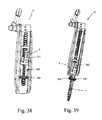
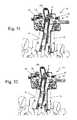
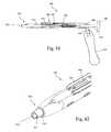
- FIG. 1is a perspective view of an example of a surgical fixation system according to one embodiment of the present invention
- FIG. 2is an exploded perspective view of the surgical fixation system of FIG. 1 ;
- FIGS. 3-5are front, perspective, and side views of the surgical fixation system of FIG. 1 ;
- FIG. 6is a partially exploded perspective view of an example of a tissue retraction system forming part of the surgical fixation system of FIG. 1 ;
- FIG. 7is an exploded perspective view of an example of a retractor body forming part of the tissue retraction system of FIG. 6 ;
- FIG. 8is a front perspective view of the retractor body of FIG. 7 ;
- FIGS. 9-10are front perspective and rear perspective views, respectively, of an example of a housing member forming part of the retractor body of FIG. 7 ;
- FIG. 11is a top perspective view of the retractor body of FIG. 8 with the housing member removed;
- FIG. 12is a top plan view of an example of a rack member forming part of the retractor body of FIG. 7 ;
- FIG. 13is a perspective view of the rack member of FIG. 12 with the second rack member removed;
- FIG. 14is an exploded perspective view of a first toggle forming part of the retractor body of FIG. 7 ;
- FIGS. 15-16are top plan and perspective views, respectively, of a medial retraction member coupled with a second toggle, forming part of the retractor body of FIG. 7 ;
- FIG. 17is an exploded perspective view of a second toggle forming part of the retractor body of FIG. 7 ;
- FIGS. 18-19are perspective views of an example of first arm member forming part of the retractor body of FIG. 7 ;
- FIGS. 20-21are perspective views of an example of a second arm member forming part of the retractor body of FIG. 7 ;
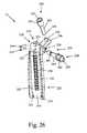
- FIGS. 22-25are various plan views of an example of a retractor blade assembly forming part of the tissue retraction system of FIG. 6 ;
- FIG. 26is an exploded view of the retractor blade assembly of FIG. 22 ;
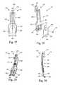
- FIGS. 27-30are front plan, perspective, rear perspective, and side plan views, respectively, of a medial retractor blade assembly forming part of the tissue retraction system of FIG. 6 ;
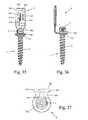
- FIGS. 31-34are perspective, exploded perspective, rear plan, and top plan views, respectively, of an example of a hoop shim assembly forming part of the surgical fixation system of FIG. 1 , the hoop shim assembly shown in an unlocked position;
- FIGS. 35-37are front plan, side plan and top plan views, respectively, of the hoop shim assembly of FIG. 31 in a locked position and engaged to a bone anchor forming part of the surgical fixation system of FIG. 1 ;
- FIG. 38is a front plan view of the hoop shim assembly of FIG. 31 being coupled to a retractor blade assembly of FIG. 22 ;
- FIG. 39is a front plan view of the hoop shim assembly locked and engaged with the bone anchor of FIG. 35 coupled to a retractor blade assembly of FIG. 22 ;
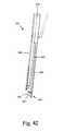
- FIGS. 40-41are perspective and side plan views, respectively, of an example of a hoop shim removal tool according to one embodiment of the present invention.
- FIG. 42is a side plan view of a distal engagement region forming part of the hoop shim removal tool of FIG. 40 ;
- FIGS. 43-45are front plan, back plan, and side plan views, respectively, of the hoop shim assembly locked and engaged with the bone anchor of FIG. 35 coupled to a retractor blade assembly of FIG. 22 , and also coupled to the hoop shim removal tool of FIG. 40 prior to disengagement of the hoop shim assembly from the bone anchor;
- FIG. 46is a perspective view of the hoop shim assembly unlocked and disengaged from the bone anchor of FIG. 35 coupled to a retractor blade assembly of FIG. 22 , and also coupled to the hoop shim removal tool of FIG. 40 after disengagement of the hoop shim assembly from the bone anchor;
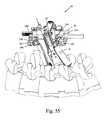
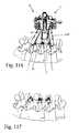
- FIGS. 47-48 and 51-53are perspective views of the surgical fixation system of FIG. 1 during different stages of use on a spinal segment;
- FIG. 49is a top plan view of the fully assembled surgical fixation system of FIG. 1 ;
- FIGS. 54 and 55are front plan and perspective views, respectively, of the fully assembled surgical fixation system of FIG. 1 in use on a spinal segment, particularly illustrating the extreme angulation capability of the system;
- FIG. 56is the front plan view of the fully assembled surgical fixation system of FIG. 49 with the spinal segment removed;
- FIG. 57is a close-up plan view of the fully assembled surgical fixation system of FIG. 49 , illustrating in particular the lockability of the system in an extreme angulation state;
- FIGS. 58-61are perspective views of a locked hoop shim assembly and bone anchor combination of FIG. 35 , with the bone anchor implanted within a bony segment, illustrating in particular the polyaxial engagement between the hoop shim assembly and bone anchor;
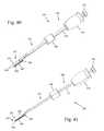
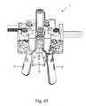
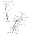
- FIGS. 62 and 63are front plan and perspective views, respectively, of the tissue retraction system of FIG. 6 having retractor blades of different lengths;
- FIG. 64is a perspective view of an example of an inserter according to one embodiment of the present invention, coupled to a bone anchor and hoop shim assembly of FIG. 35 and retractor blade of FIG. 22 ;
- FIG. 65is a perspective view of a distal region of the inserter, bone anchor, hoop shim assembly, and retractor blade combination of FIG. 64 ;
- FIG. 66is a perspective view of the inserter of FIG. 64 ;
- FIG. 67is an exploded perspective view of the inserter of FIG. 64 ;
- FIGS. 68-70are plan, perspective, and sectional views, respectively, of a receiver member forming part of the inserter of FIG. 64 ;
- FIGS. 71 and 72are perspective views of a distal end of a receiver assembly forming part of the inserter of FIG. 64 ;
- FIG. 73is a perspective view of a receiver assembly forming part of the inserter of FIG. 64 ;
- FIG. 74is a perspective view of a driver member forming part of the inserter of FIG. 64 ;
- FIG. 75is a perspective view of a distal end of the driver member of FIG. 74 ;
- FIG. 76is a perspective view of a distal end of the driver member of FIG. 74 coupled with the receiver assembly of FIG. 71 ;
- FIG. 77is a perspective view of a distal end of the driver member of FIG. 74 coupled with the receiver assembly of FIG. 72 ;
- FIG. 78is a perspective view of a blade engagement assembly forming part of the inserter of FIG. 64 ;
- FIG. 79is a perspective view of an example of a hoop shim reattachment tool according to one embodiment of the present invention.
- FIG. 80is an exploded perspective view of the hoop shim reattachment tool of FIG. 79 ;
- FIG. 81is a side cross-section view of the hoop shim reattachment tool of FIG. 79 ;
- FIG. 82is an enlarged perspective view of the distal end region of the hoop shim reattachment tool of FIG. 79 ;
- FIGS. 83-84illustrate another example embodiment of a hoop shim reattachment tool.
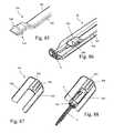
- FIG. 85is a perspective view of the distal end of a light cable, according to one example embodiment of the present invention.
- FIG. 86is a perspective view of the distal end of the light cable of FIG. 85 engaged to the retractor blade of FIG. 22 and extending over the proximal end of the hoop shim of FIG. 31 ;
- FIG. 87is a perspective view of a tissue shim according to one example embodiment of the present invention.
- FIG. 88is a perspective view of the tissue shim of FIG. 87 illustrating the manner in which the shim element of the hoop shim nestles between wings of the tissue shim;
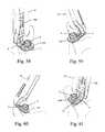
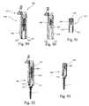
- FIG. 89is a front view of an alternate retractor blade for use with the surgical fixation system of FIG. 1 , according to one example embodiment
- FIG. 90is a front view of the retractor blade of FIG. 89 with a track insert removed;
- FIG. 91is a front view of a track insert forming part of the retractor blade of FIG. 89 ;
- FIG. 92is a front view of the retractor blade of FIG. 89 with the hoop shim of FIG. 31 engaged;
- FIG. 93is a front view of the track insert of FIG. 92 with the hoop shim engaged and the remainder of retractor blade removed;
- FIG. 94is a perspective view of a guide instrument for use with the retractor blade of FIG. 89 , according to one example embodiment
- FIG. 95is an exploded perspective view of the guide instrument of FIG. 94 ;
- FIG. 96is a perspective view of the distal end of the body portion of the guide instrument of FIG. 94 ;
- FIG. 97is a perspective view of an actuator of the guide instrument of FIG. 94 ;
- FIG. 98is a perspective view of the distal end of a driver of the guide instrument of FIG. 94 ;
- FIG. 99is a perspective view of the housing forming part of the body portion of FIG. 96 ;
- FIG. 100is a cross section view of the housing of FIG. 99 showing the actuator of FIG. 97 and the driver of FIG. 98 interacting therein;
- FIG. 101is a perspective view of the guide instrument of FIG. 94 engaged to the retractor blade and track insert of FIG. 89 ;
- FIG. 102is an enlarged view of the distal end of the guide instrument of FIG. 94 engaged to the retractor blade and track insert of FIG. 89 ;
- FIGS. 103-105are perspective, front and front views of an example embodiment of an ambiblade, for use, for example, at the center level(s) of a multilevel case;
- FIG. 106-107illustrate one example embodiment of an adjustable connection post of the ambiblade of FIGS. 103-105 ;
- FIGS. 108-109illustrate one example embodiment of wing shims that may be used with the ambiblades of FIGS. 103-105 ;
- FIGS. 110-117are perspective view of the spinal fixation system of FIG. 1 including the retractor blade of FIG. 89 in use during various steps of a multi-level spinal fusion procedure;
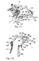
- FIGS. 118-120illustrate one example embodiment of a fourth blade assembly that may be used with the tissue retraction system of FIG. 6 ;
- FIGS. 121-125illustrate another example embodiment of a fourth blade assembly that may be used with the tissue retraction system of FIG. 6 ;
- FIGS. 126-127illustrate one example embodiment of the locking mechanism between a connector of the fourth blade assembly and the center blade of the retractor system of FIG. 6 to which the connector attaches;
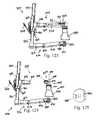
- FIGS. 128-130illustrate one example embodiment of a fourth blade for use with the fourth blade assemblies of FIGS. 118-120 and 121-125 ;
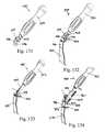
- FIGS. 131-132illustrate one example embodiment of a insertion instrument for inserting the fourth blade of FIGS. 128-130 ;
- FIGS. 133-134illustrate another example embodiment of a insertion instrument for inserting the fourth blade of FIGS. 128-130 ;
- FIGS. 1-5illustrate an example of a surgical fixation system 5 according to one embodiment of the present invention.
- the surgical fixation system 5includes a variety of sub-components dimensioned to allow for retraction of a soft tissue in order to establish an operative corridor through a patient's skin to a surgical target site.
- the surgical target site referred to herein throughoutis an intervertebral disc space situated between two adjacent vertebrae.
- the surgical fixation system of the present inventionmay be employed in any number of suitable orthopedic fixation approaches and procedures, including but not limited to anterior, posterior, lateral, anterolateral, posterolateral, cervical spine fixation, thoracic spine fixation, as well as any non-spine fixation application such as bone fracture treatment.
- the surgical fixation system 5includes a tissue retraction assembly 10 , a plurality of hoop shims 6 , and a plurality of bone anchors 7 .
- the tissue retraction system 10includes retractor body 12 , a first retractor blade 14 , a second retractor blade 16 , and a third retractor blade 18 (also referred to herein throughout as the medial blade 18 ).
- the retractor blades 14 , 16 , 18may be provided in any size and shape suitable to establish and maintain an operative corridor to the surgical target site, however, certain benefits may be achieved utilizing one or more aspects of the various shaped retractor blades described, which features should be apparent from the discussion herein.
- the bone anchor 7may be one of the type shown and described in U.S. patent application Ser. No. 12/820,136, filed Jun. 21, 2010 and entitled “Polyaxial Bone Screw Assembly,” the entire contents are hereby incorporated by reference into this disclosure as if set forth fully herein.
- the tissue retraction assembly 10may be configured such that the retractor blades 14 , 16 , 18 may be advanced to the surgical target site individually (e.g. sequentially) or together (e.g. simultaneously). For example, for simultaneous advancement, two or more of the retractor blades 14 , 16 , 18 may be attached to the retractor body prior to advancement to a surgical target site.
- the tissue retraction assembly 10is particularly suitable for individual advancement of each blade 14 , 16 , 18 to a surgical target site.
- the first retractor blade 14may be advanced through an incision and securely attached to a first bone segment within the surgical target site.
- the second retractor blade 16may then be advanced through an incision and securely attached to a second bone segment within the surgical target site.
- the retractor blades 14 , 16may then be attached to the retractor body 12 .
- first and second retractor blades 14 , 16may be further moved by the retractor assembly to a second “open” position to establish and maintain a second operative corridor (or working channel).
- This operative corridormay be variable in size and approach angle to the surgical target site, providing the ability to establish numerous custom working channels.
- the medial retractor blade 18may then be attached to the retractor body 12 and used as desired.
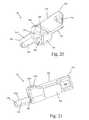
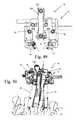
- the retractor body portion 12includes a housing member 20 , a rack member 22 , a medial retraction member 24 , a first retractor arm 26 , a second retractor arm 28 , a first toggle 30 , and a second toggle 32 .
- the housing member 20provides a scaffold to hold the various components together.
- the rack member 22provides a mechanism to expand the operative corridor in a caudal-cranial direction by moving the retractor blades 14 , 16 toward or away from one another.
- the medial retraction member 24provides a mechanism to expand the operative corridor in a medial direction by moving the medial retractor blade 18 away from the first and second retractor blades 14 , 16 .
- the first retractor arm 26couples to the first retractor blade 14 , and as will be explained in detail below, is configured to enable the first retractor blade 14 to retract nearby soft tissue and/or distract the first bone segment.
- the second retractor arm 28couples to the second retractor blade 16 , and is configured to enable the second retractor blade 16 to retract nearby soft tissue and/or distract the second bone segment.
- the first toggle 30controls the caudal-cranial movement of the first and second retractor arms 26 , 28 , and therefore the first and second retractor blades 14 , 16 .
- the second toggle 32controls the medial movement of the medial retraction member 24 , and therefore the medial blade 18 .
- the housing member 20has a front side 34 , a back side 36 , an upper portion 38 , and a lower portion 40 .
- the housing member 20further includes a first recess 42 extending axially through the upper portion 38 from the front side 34 to the back side 36 .
- the first recess 42is configured to receive the medial retraction member 24 therein.
- the first recess 42include a pair of track grooves 44 that are configured to engage with flanges 110 , 112 on the medial retraction member 24 to secure the medial retraction member to the housing 20 .
- the first recess 42further includes a tapered surface 46 extending from the front side of the first recess 42 toward the front side 34 of the housing member 20 .
- This tapered surface 46enables medial-lateral angulation of the medial retraction member 24 while in a retracted position.
- the tapered surface 46is flanked by a pair of curved surfaces 48 that enable caudal-cranial pivoting of the medial retraction member 24 while in a retracted position.
- the upper portion 38further includes a second recess 50 and a third recess 52 , formed within the housing member 20 on either side of the first recess 42 .
- the second recess 50is configured to receive the first toggle 30 therein.
- the second recess 50is dimensioned to allow for movement of the toggle 30 therein to enable the toggle 30 to perform its function, which is explained in further detail below.
- the third recess 52is configured to receive the second toggle 32 therein.
- the third recess 52is dimensioned to allow for movement of the toggle 32 therein to enable the toggle 32 to perform its function, which is explained in further detail below.
- the upper portion 38further includes at least one attachment member 53 dimensioned to enable attachment of the retractor body 12 to an articulating arm (not shown) within the operative field. This attachment to the articulating arm ensures that the surgical retraction system 10 is securely registered to the operating table.
- the upper portionmay also be provided with at least one aperture 55 dimensioned to receive a tool (not shown) configured to allow the operator to alter the position of the retractor body 12 in order to adjust the angle of the operative corridor.
- the lower portion 40includes a first lumen 54 extending axially through the housing member 20 transverse to the first recess 42 .
- the first lumenhas a generally rectangular cross-section and is configured to slideably receive the first rack member 58 therethrough.
- the lower portion 40further includes a second lumen 56 extending axially through the housing member 20 transverse to the first recess 42 and parallel to the first lumen 54 .
- the second lumen 56has a generally rectangular cross section and is configured to slideably receive the second rack member 60 therethrough.
- FIG. 11illustrates the retractor body 12 without the housing member 20 to provide a clear view of the rack 22 .
- the rack 22includes a first rack member 58 and a second rack member 60 .
- the first rack member 58is an elongated axial member having a generally rectangular cross section and a first end 62 , a second end 64 , and an elongated body 66 extending therebetween. Although shown and described as generally rectangular, other cross sectional shapes are possible without departing from the scope of the present invention.
- the first rack member 58is dimensioned to be slideably received within the first lumen 54 of the housing member 20 .
- the first end 62is connected to the first retractor arm 26 .
- the first rack member 58further includes a plurality of teeth 68 on one surface, the teeth being provided along substantially the length of the first rack member 58 .
- the teethinteract with the first toggle 30 to allow controlled caudal-cranial movement of the first retractor blade 14 , as will be described.
- the second rack member 60is an elongated axial member having a generally rectangular cross section and a first end 70 , a second end 72 , and an elongated body 74 extending therebetween. Although shown and described as generally rectangular, other cross sectional shapes are possible without departing from the scope of the present invention.
- the second rack member 60is dimensioned to be slideably received within the second lumen 56 of the housing member 20 .
- the first end 70is connected to the second retractor arm 28 .
- the second rack member 60further includes a plurality of teeth 76 on one surface, the teeth being provided along substantially the length of the second rack member 60 . The teeth interact with the first toggle 30 to allow controlled caudal-cranial movement of the second retractor blade 16 , as will be described.
- the first toggle 30includes an actuator 78 , a gear 80 , and a release member 82 .
- the actuator 78includes a superior handle portion 84 that includes a friction feature that enables a user to grip and turn the handle portion 84 .
- the handle portion 84is provided with a friction feature comprising a plurality of planar surfaces 86 (for engagement with a rotation handle), however other friction features are possible, for example ridges, knobs, dimples, and/or a material overlay such as rubber that provides for adequate gripping by a user.
- the actuator 78further includes an inferior post 88 that extends away from the handle portion 84 .
- the inferior post 88includes at least one generally planar surface 90 configured to mate with the planar surface 93 of the gear 80 and transfer the torque applied by a user to the handle portion 84 to the gear 80 , thus turning the gear 80 .
- the inferior post 88further includes a recess 92 for receiving a snap ring 95 , which functions to secure the first toggle 30 to the housing member 20 .
- the gear 80has a generally circular cross-section and includes a central lumen 91 extending therethrough and a plurality of teeth 94 in the form of vertical ridges distributed about the perimeter of the gear 80 .
- the central lumen 91includes a planar surface 93 configured to mate with the planar surface 90 of the actuator 78 to transfer the torque applied by a user to the handle portion 84 to the gear 80 , thus turning the gear 80 .
- the teeth 94 of the gear 80are configured to mate with the teeth 68 , 76 of the first and second rack members 58 , 60 . As shown by way of example in FIG.
- the first toggle 30is positioned between the first and second rack members 58 , 60 such that the teeth 94 of the gear 80 simultaneously engages the teeth 68 of the first rack member 58 and the teeth 76 of the second rack member 60 .
- the gear 80causes the first and second racks 58 , 60 to simultaneously move in opposite directions. For example, when the handle portion 84 is rotated in a clockwise direction, the first rack 58 will move in a cranial direction (assuming proper placement of the retractor relative to the spine) and the second rack 60 will move in a caudal direction.
- first retractor blade 14through its connection to the first arm 26 (which is connected to the first rack member 58 ) will move in a cranial direction and the second retractor blade 16 , through its connection to the second retractor arm 28 (which is connected to the second rack member 60 ) will move simultaneously in a caudal direction.
- the release member 82includes body 96 , a tab 98 , and a flange 100 .
- the body 96is a generally circular member having a central lumen 102 extending therethrough.
- the central lumen 102is dimensioned to receive the post 88 of the actuator 78 .
- the tab 98extends radially from the body and functions as a manipulation point for the user.
- the flange 100includes a ratchet member 104 that is dimensioned to interact with the teeth 68 of the first rack member 58 .
- the release member 82further includes a spring 106 that biases the ratchet member 104 into an engaged position relative to the teeth 68 .
- the ratchet member 104clicks into engagement with each passing tooth 68 .
- the ratchet member 104provides for controlled translation of the first and second rack members 58 , 60 , and creating a customizable operative corridor established in incremental amounts.
- the ratchet member 104further prevents unwanted migration of the first rack member 58 (and therefore the second rack member 60 as well) such that the desired operative corridor will not alter once established.
- the ratchet member 104is configured to allow for unidirectional movement of the first rack member 58 relative thereto while the ratchet member 104 is engaged to the gear 80 .
- the ratchet member 104effectively prevents counterclockwise turning of the handle member 84 .
- the useractivates the tab 98 , causing the ratchet member 58 to disengage from the teeth 68 .
- Thisallows for free (though still simultaneous) translation of the first and second rack members relative to the housing member 20 . That is, a counterclockwise turning of the handle member 84 will cause the first and second rack members 58 , 60 to translate in an opposite direction, such that the first retractor blade 14 will move in a caudal direction and the second retractor blade 16 will move in a cranial direction.
- FIGS. 15-17illustrate the medial retraction member 24 in greater detail.
- the medial retraction member 24comprises a medial rack 108 dimensioned to fit in the first recess 42 of the housing member 20 .
- the medial rack 108is an elongated axial member having a generally rectangular cross section.
- the medial rack 108includes a first flange 110 and a second flange 112 , each extending the length of the medial rack 108 and dimensioned to engage the overhangs 44 of the first recess 42 .
- the first flange 110includes a plurality of teeth 114 in the form of vertical ridges that are distributed along the length of the first flange 110 .
- the medial rack 108further includes a post 116 extending axially from the front end of the medial rack 108 .
- the post 116is configured for engagement with the medial blade 18 .
- the post 116has an end portion 118 having a first diameter and a recessed portion 120 between the end portion 118 and the medial rack 108 , the recessed portion 120 having a reduced diameter relative to the end portion 118 . This configuration allows for engagement, for example a snap-fit engagement, with the medial blade 18 .
- the medial rackfurther includes at least one attachment member 109 dimensioned to enable attachment of the medial retraction member 24 to an articulating arm (not shown) within the operative field.
- This attachment to the articulating armensures that the surgical retraction system 10 is securely registered to the operating table.
- the attachment member 109 on the medial retraction member 24is structurally identical to, and performs the same function as, the attachment member 53 of the housing member 20 ( FIGS. 10-11 ). However, attachment to the attachment member 109 of the medial retraction member 24 provides an entirely different effect than attachment to the attachment member 53 of the housing member 20 . Specifically, attachment to the attachment member 109 registers the medial retraction member 24 to the articulating arm, and therefore the surgical table.
- the medial retraction member 109is secured in place, and actuation of the toggle 32 will therefore cause the retractor body 12 , to move laterally relative to the patient.
- the actuation of the toggle 32will cause the medial retraction member 24 to move medially relative to the patient. This feature is advantageous in situations in which the medial blade 18 has been placed, but for some reason the surgeon would prefer to move the operative corridor laterally relative to the spine rather than medially.
- the second toggle 32includes an actuator 122 , a gear 124 , and a release member 126 .
- the actuator 122includes a superior handle portion 128 that includes a friction feature that enables a user to grip and turn the handle portion 128 .
- the handle portion 128is provided with a friction feature comprising a plurality of planar surfaces 130 , however other friction features are possible, for example ridges, knobs, dimples, and/or a material overlay such as rubber that provides for adequate gripping by a user.
- the actuator 122further includes an inferior post 132 that extends away from the handle portion 128 .
- the inferior post 132includes at least one generally planar surface 134 configured to mate with the planar surface 127 of the gear 124 and transfer the torque applied by a user to the handle portion 128 to the gear 124 , thus turning the gear 124 .
- the inferior post 132further includes a recess 136 for receiving a snap ring 138 , which functions to secure the second toggle 32 to the housing member 20 .
- the gear 124has a generally circular cross-section and includes a central lumen 125 extending therethrough and a plurality of teeth 140 in the form of vertical ridges distributed about the perimeter of the gear 124 .
- the central lumen 125includes a planar surface 127 configured to mate with the planar surface 134 of the actuator 122 to transfer the torque applied by a user to the handle portion 128 to the gear 124 , thus turning the gear 124 .
- the teeth 140 of the gear 124are configured to mate with the teeth 114 of the medial rack member 108 .
- the second toggle 32is positioned adjacent the medial rack member 108 .
- the gear 124causes the medial rack 108 to translate in a medial (or lateral) direction.
- the medial rack 128will move in a medial direction (i.e. toward the spinal column, assuming proper placement of the retractor relative to the spine).
- the effect of this movementis that the medial retractor blade 18 , through its connection to the medial rack 108 will move in a medial direction, thereby retracting soft tissue and expanding the operative corridor.
- the medial rack 108thus contributes to the customizable nature of the operative corridor.
- the release member 126includes body 142 , a tab 144 , and a flange 146 .
- the body 142is a generally circular member having a central lumen 148 extending therethrough.
- the central lumen 148is dimensioned to receive the post 132 of the actuator 122 .
- the tab 144extends radially from the body and functions as a manipulation point for the user.
- the flange 146includes a ratchet member 150 that is dimensioned to interact with the teeth 114 of the medial rack member 108 .
- the release member 126further includes a spring 152 positioned between the tab 144 and the housing 20 that biases the ratchet member 150 into an engaged position relative to the teeth 114 .
- the ratchet member 150clicks into engagement with each passing tooth 114 .
- the ratchet member 150provides for controlled translation of the medial rack member 108 , and creating a customizable operative corridor established in incremental amounts.
- the ratchet member 150further prevents unwanted migration of the medial rack member 108 such that the desired operative corridor will not alter once established.
- the ratchet member 150is configured to allow for unidirectional movement of the medial rack member 108 relative thereto while the ratchet member 150 is engaged to the gear 124 .
- the ratchet member 150effectively prevents counterclockwise turning of the handle member 128 .
- the useractivates the tab 144 , causing the ratchet member 108 to disengage from the teeth 114 .
- Thisallows for free translation of the medial rack member 108 relative to the housing member 20 . That is, a counterclockwise turning of the handle member 128 with the ratchet member 150 disengaged will cause the medial rack member 108 to translate in an opposite direction (e.g. lateral direction, away from the spine.
- FIGS. 18-19illustrate the first arm member 26 in greater detail.
- the first arm member 26includes a front body portion 160 , a rear body portion 162 , a first flange 164 , and a second flange 166 .
- the front body portionincludes a front surface 168 and a top surface 170 .
- the front surface 168includes an aperture 172 formed therein and extending into the front body portion 160 .
- the aperture 172is dimensioned to receive the engagement post 230 of the first retractor blade 14 ( FIG. 6 ) to enable engagement of the first retractor blade 14 to the retractor body 12 .
- the top surface 170includes a second aperture 174 configured to receive a set screw 176 ( FIG. 7 ).
- the set screw 176functions to lock the engagement post 230 within the aperture 172 , preventing unwanted ejection of the first retractor blade 14 from the first arm member 26 .
- the rear body portionincludes a lower-facing inside tapered surface 178 that allows the medial blade 18 to pivot within a plane that is transverse to the longitudinal axis of the medial rack member 108 . This pivoting enables intraoperative repositioning of the retractor body 12 relative to the surgical target site without the need to detach the retractor body 12 from the articulating arm. The net effect is to alter the approach angle of the operative corridor relative to the surgical target site.
- the first flange 164extends axially from the rear body portion 162 and includes a third aperture 180 and fourth aperture 182 .
- the third aperture 180is configured to securely mate with the first end 62 of the first rack member 58 such that the first arm member 26 moves with the first rack member 58 .
- the first arm member 26can be securely mated with the first rack member 58 by welding, adhesive, snap-fit, friction-fit, or any other suitable method.
- the first arm member 26can be integrally formed with the first rack member 58 without departing from the scope of the present invention.
- the fourth aperture 182is configured to allow passage of the second rack member 60 therethrough.
- the third and fourth apertures 180 , 182are generally rectangular in shape, however other shapes are possible depending on the cross-sectional shapes of the first and second rack members 58 , 60 .
- the second flange 166extends axially from the front body portion 160 and includes a generally planar upper surface 184 and a curved medial surface 186 .
- the second flange 166interacts with the thumbscrew 240 of the first retractor blade 14 and functions as a shelf to enable the lockable adjusted angulation feature of the first retractor blade 14 , as well as an alternative distraction feature of the tissue retraction system 10 , each of which will be described in greater detail below.
- FIGS. 20-21illustrate the second arm member 28 in greater detail.
- the second arm member 28includes a front body portion 190 , a rear body portion 192 , a first flange 194 , and a second flange 196 .
- the front body portionincludes a front surface 198 and a top surface 200 .
- the front surface 198includes an aperture 202 formed therein and extending into the front body portion 190 .
- the aperture 202is dimensioned to receive the engagement post 230 of the second retractor blade 16 ( FIG. 6 ) to enable engagement of the second retractor blade 16 to the retractor body 12 .
- the top surface 200includes a second aperture 204 configured to receive a set screw 206 ( FIG. 7 ).
- the set screw 206functions to lock the engagement post 230 within the aperture 202 , preventing unwanted ejection of the second retractor blade 16 from the first arm member 28 .
- the rear body portionincludes a lower-facing inside tapered surface 208 that that allows the medial blade 18 to pivot within a plane that is transverse to the longitudinal axis of the medial rack member 108 . This pivoting enables intraoperative repositioning of the retractor body 12 relative to the surgical target site without the need to detach the retractor body 12 from the articulating arm. The net effect is to alter the approach angle of the operative corridor relative to the surgical target site.
- the first flange 194extends axially from the rear body portion 192 and includes a third aperture 210 .
- the third aperture 210is configured to securely mate with the first end 70 of the second rack member 60 such that the second arm member 28 moves with the second rack member 60 .
- the second arm member 28can be securely mated with the second rack member 60 by welding, adhesive, snap-fit, friction-fit, or any other suitable method.
- the second arm member 28can be integrally formed with the second rack member 60 without departing from the scope of the present invention.
- the third aperture 210is generally rectangular in shape, however other shapes are possible depending on the cross-sectional shapes of the second rack member 60 .
- the second flange 196extends axially from the front body portion 190 and includes a generally planar upper surface 214 and a curved medial surface 216 .
- the second flange 196interacts with the thumbscrew 240 of the second retractor blade 16 and functions as a shelf to enable the lockable adjusted angulation feature of the second retractor blade 16 , as well as an alternative distraction feature of the tissue retraction system 10 , each of which will be described in greater detail below.
- the retractor blades 14 , 16may be provided in any size or shape suitable to establish and maintain an operative corridor to the surgical target site.
- the retractor blades 14 , 16can be individually selected for appropriate length. Therefore, the retractor blades 14 , 16 can be of different lengths which gives the surgeon additional control over the shape and size of the operative corridor (as shown for example in FIGS. 62 and 63 ).
- the retractor blades 14 , 16may be provided having a generally arcuate cross-section to facilitate a circular or generally oblong surgical corridor.
- FIGS. 22-25illustrate an example of a first retractor blade 14 according to the present invention.
- FIG. 26is an exploded view of the first retractor blade 14 .
- first retractor blade 14For the purposes of illustration, the specific features of the invention will be described in relation to the first retractor blade 14 . However it should be understood that the features described in relation to first retractor blade 14 are the same for second retractor blade 16 , but provided in a mirror-image configuration. Thus, though the first and second retractor blades 14 and 16 are not strictly interchangeable, the features of each blade are virtually identical rendering a repeat discussion unnecessary as cumulative.
- the first retractor blade 14includes an attachment portion 220 and a blade portion 222 extending distally from the attachment portion 220 .
- the attachment portion 220has a front side 224 , a back side 226 , and a top surface 227 .
- the back side 226includes a first aperture 228 extending into the upper attachment portion 220 and configured to receive an engagement post 230 therein.
- the engagement post 230is configured to mate with the aperture 172 of the first arm member 26 to couple the first retractor blade 14 with the retractor body 12 .
- the engagement post 230is configured to mate with the aperture 202 of the second arm member 28 to couple the second retractor blade 16 with the retractor body 12 .
- the attachment portion 220further includes a pair of second apertures 232 extending through the attachment portion 220 parallel to one another and transverse to the first aperture 228 .
- the second apertures 232are vertically offset from the first aperture 228 but are at least partially in communication with the first aperture 228 .
- the second apertures 232are configured to receive pins 234 that operate to secure the engagement post 230 to the retractor blade 14 (explained in further detail below).
- the attachment portionfurther includes a flange 236 extending angularly (relative to the top surface 227 ) therefrom, the flange 236 including an aperture 238 configured to receive a thumb screw 240 therein.
- the flange 236 and thumb screw 240interact with the second flange 166 of the first arm member 26 to enable the lockable angulation feature of the first retractor blade 14 , as well as an alternate tissue distraction feature of the tissue retraction system 10 , as will be described in greater detail below.
- both the thumb screw 240 and aperture 238include threads to enable a threaded engagement therebetween.
- the flange 236is angularly offset from the top surface 227 within a range of 15 to 50 degrees, with the preferable angle being approximately 30 degrees.
- the thumbscrew 240includes a head 241 , a shaft 243 , and a distal tip 245 .
- the head 241is generally cylindrical in shape and includes a rotation feature that enables the user to rotate the thumb screw 240 .
- the rotation featuremay be anything that is suitable to enable rotation of the thumb screw 240 , for example including but not limited to a socket 247 for receiving a driver as shown in FIGS. 22, 23 and 26 , and/or an external planar surfaces 249 to provide gripping for a driver or a user's hand, as shown in FIGS. 24 and 25 .
- the blade portion 222extends distally from the attachment portion 220 and includes an outside surface 242 , an inside surface 244 , a first lip 246 , and a second lip 248 .
- the outside surfaceis a smooth arcuate surface configured to interact with the patient's soft tissue near the operative corridor.
- the outside surface 242extends from the attachment portion 220 at a non-orthogonal angle relative to the top surface 227 . Since much of the blade has a generally uniform thickness, the inside surface 244 extends from the attachment portion 220 at the same non-orthogonal angle relative to the top surface 227 .
- the effectis that the operative corridor is immediately established having a conical shape with no further adjustment of the tissue retraction assembly 10 required.
- the blade portion 222extends from the attachment portion 220 such that the blade face (i.e. inner surface 244 ) is oriented orthogonal to the attachment portion 220 .
- the inside surface faces 244 the operative corridorat an angle rather than facing directly at the opposing blade, for example between 20 and 60 degrees). This orientation of the blade portion relative to the attachment portion helps optimize the shape (e.g. triangular) of the operative corridor.
- the inside surface 244includes a plurality of notches or recesses 250 arranged in a linear alignment thereon, the notches or recesses 250 being configured to interact with the knob 498 of the inserter 400 , as will be described in further detail below.
- the blade portion 222further includes a pair of track grooves 252 spaced apart from one another and extending the length of the inside surface 244 .
- the track grooves 252are configured to slideably receive a shim attachment, for example the hoop shim 6 shown and described herein. It should be understood, however, that any suitable shim attachment may be used without departing from the scope of the present invention.
- each of the track grooves 252there is a stop 254 , which interacts with the hoop shim 6 to prevent the hoop shim 6 from passing the stop 254 once it has been fully engaged to the retractor blade.
- the first lip 246 and second lip 248comprise edges of the blade portion 222 and each extend along the length of the blade portion 222 from the attachment portion 222 to the distal end of the blade portion 222 .
- the first and second lips 246 , 248are asymmetric relative to one another.
- the first lip 246has a concave portion 256 that allows for clearance of spinal anatomy during blade angulation.
- the engagement post 230includes a boss 258 and a post 260 .
- the boss 258is generally cylindrical in shape and is dimensioned to be received within the aperture 172 of the first arm member 26 to couple the first retractor blade 14 with the retractor body 12 .
- the boss 258includes a recess 262 formed therein, the recess 262 configured to receive at least a portion of the set screw 176 to securely engage the first retractor blade 14 to the retractor body 12 .
- the post 260extends axially from the boss 258 and is configured to be received within aperture 228 of the first retractor blade 14 .
- the post 260further includes a recess 264 formed therein, the recess 264 being sized and dimensioned to receive at least a portion of both pins 234 therein.
- the pins 234extend transversely relative to the post 260 , and prevent undesirable uncoupling of the post 230 from the first retractor blade 14 .
- the retractor blade 14(and retractor blade 16 ) is provided with the post 230 already secured within the aperture 228 with the pins 234 in place.
- the pins 234may be secured by any suitable method, including for example welding, that ensures that the pins 234 securely retain the post 230 within the aperture 238 .
- any suitable attachment mechanismcan be used without departing from the scope of the present invention.
- a quick connection mechanismsuch as a snap fit engagement is possible, as is a friction engagement or an integral blade.
- the medial retractor blade 18may be provided in any size or shape suitable to establish and maintain an operative corridor to the surgical target site.
- the medial retractor blade 18includes an attachment portion 270 and a blade portion 272 .
- the attachment portion 270includes a knob 274 and an aperture 276 .
- the knob 274is configured to allow manipulation by a user, for example to change the angulation of the medial retractor blade 18 .
- the knobalso connects to a manual insertion tool (not shown).
- the manual insertion toolincludes a cylinder with a canted coil received in a notch therein. In a natural position, the coil extends into the cylinder.
- the tapered end of the knob 274deflects the canted coil as the knob passes. When the coil reaches the groove 275 formed in the knob, the coil returns to the natural position and secures the blade to the manual inserter.
- the aperture 276extends into the attachment portion 270 and is configured to receive the post 116 of the medial retraction member 24 therein to securely attach the medial retractor blade 18 to the retractor body 12 .
- the engagement between the medial retractor blade 18 and the post 116is provided by way of example as a snap-fit engagement allowing for relative easy insertion and/or removal of the medial retractor blade 18 .
- other engagementsare possible without departing from the scope of the present invention, including but not limited to using a set screw (e.g.
- the blade portion 272includes an upper portion 280 and a lower portion 282 .
- the upper portion 280is adjacent to the attachment portion 270 and extends generally orthogonally therefrom.
- the lower portion 282is located distally of the upper portion 280 and is offset from the upper portion 280 such that it forms an obtuse angle with the upper portion 280 (best shown in FIG. 30 ).
- the offsetis such that the distal end of the lower portion 282 is offset from the plane of the upper portion 280 by approximately one-quarter of an inch.
- the angle formed between the upper and lower portions 280 , 282is variable to achieve this one-quarter inch offset.
- the lower portion 282is wider than the upper portion to accommodate the retraction of a greater amount of the patient's soft tissue near the surgical target site.
- the lower portion 282includes a recess 284 configured to receive a blade extension 290 therein.
- the recess 284includes an elongated central slot 286 formed therein and configured to receive a guide extension 292 therein.
- the recess 284may further include a pair of elongated lateral slot 288 formed therein on either side of the central aperture 286 .
- a blade extension 290may be provided to enhance the functionality of the medial retractor blade 18 .
- the blade extension 290is received within the recess 284 and is coupled to the medial blade 18 by the fastener 292 .
- the blade extension 290is slideably coupled to the medial blade 18 .
- the fastener 292is slideably received within the elongated central aperture 286 .
- the blade extension 290includes a front surface 294 and a back surface 296 . In use, the blade extension 290 is oriented such that the front surface 294 faces the operative corridor, and the back surface 296 engages the patient's soft tissue.
- the blade extension 290may be generally curved such that the front surface 294 has a concave curvature and the back surface 296 has a convex curvature or it may the front and back may be generally flat.
- the blade extension 290further includes a distal anchor element 298 provided thereon.
- the distal anchor element 298comprises a roughened surface including a series of ridges and spike members that enable the clearing away of soft tissue from the surgical target site.
- the distal anchor element 298has two aspects of curvature. The first aspect of curvature is that the distal anchor element 298 curves toward the back surface 296 .
- the second aspect of curvatureis that the front surface 294 maintains its concave curvature.
- the distal anchor element 298acts much the same way as a “boat anchor” in that it is capable of travelling along the surgical target site, displacing soft tissue until the distal anchor element 298 engages hard tissue such as bone.
- the distal anchor element 298advantageously removes soft tissue from the facet as it is being retracted, saving the surgeon from having to manually clean the facet. Due to its unique shape, the distal engagement element 298 will either penetrate the bone or become wedged underneath the bone.
- the blade extension 290is slideably coupled to the medial blade 18 such that, upon tilting or other movement of the surgical retraction system 10 , the blade extension 290 will remain stationary relative to the bone segment while the medial retractor blade 18 moves relative to the blade extension 290 .
- the blade extension 290is therefore capable of telescoping (i.e. extending or retracting) to conform to anatomy during retraction, both with and/or without manual adjustments from the surgeon.
- the bladeelongates since it is secured distally at the bone and proximally at the retractor body 12 .
- the surgeonis able to further optimize, customize, and alter the operative corridor without having to disengage the retractor and/or any blades, while ensuring the exposure at the surgical target site (the base of the operative corridor) does not change, and thereby preventing previously retracted soft tissue from entering the operative corridor under the blade.
- the blade extension 290may be mechanically biased toward the extended position in order to ensure that its tissue clearing functionality is maximized. This may be accomplished, for example, by including a spring member (not shown) attached to the medial blade 18 and configured to bias the blade extension 290 in the distal direction.
- FIGS. 31-34illustrate an example of a hoop shim assembly 6 according to one embodiment of the present invention.
- the hoop shim assembly 6includes a hoop portion 300 slideably engaged with a shim portion 302 .
- the hoop portion 300includes a hoop member 304 , a first flange 306 and a second flange 308 extending proximally from the hoop member 304 .
- the hoop member 304is a generally circular member having a central aperture 310 configured to receive a bone anchor 7 therein.
- the hoop member 304has a first, unlocked position having a first diameter allowing passage of the bone anchor 7 therethrough. In this first position, the head of the bone anchor 7 may pass through, but with resistance.
- the hoop member 304further has a second, locked position, having a second diameter that does not allow passage of the head of the bone anchor 7 therethrough.
- the bone anchor 7is secured to the hoop shim 6 .
- this secured engagementdoes not mean that the bone anchor 7 is immobilized—on the contrary it is a polyaxial engagement (as illustrated in FIGS. 58-61 ).
- the hoop member 304may be optionally provided with an insert 312 ( FIGS. 35-37 ) to provide protective interaction with the bone anchor 7 .
- the insert 312protects the neck of the bone anchor 7 from a metal-on-metal contact with the hoop shim 6 , which could ultimately weaken the bone anchor 7 .
- the insert 312may be composed of any suitable materials, including but not limited to polyetheretherketone (PEEK).
- the first flange 306is generally elongated and extends generally perpendicularly in a proximal direction from the hoop member 304 .
- the first flangehas a wing 314 extending at least partially along the length of the flange 306 from the proximal end toward the distal end.
- the wing 314is dimensioned to engage one of the track grooves 252 of the first retractor blade 14 (and/or second retractor blade 16 ) to enable slideable engagement of the hoop shim assembly 6 with the retractor blade 14 (as shown in FIG. 38 , for example).
- the first flange 306further includes a tab member 316 projecting in a forward direction (i.e. same direction as the hoop member 304 ).
- the tab member 316is generally rectangular and configured to slideably engage the vertical slot 338 of the shim portion 302 .
- the tab member 316has a generally U-shaped retaining pin 318 attached thereto that prevents the tab member 316 from becoming disengaged with the vertical slot 338 during use.
- the retaining pin 318is welded to the tab member 316 during assembly of the hoop shim assembly 6 , however other attachment methods are possible without departing from the scope of the present invention.
- the tab member 316 and retaining pin 318may be integrally formed with one another and then welded onto the first flange 306 .
- a retaining platemay be welded over the tab instead of the retaining pin.
- the second flange 308is generally elongated and extends generally perpendicularly in a proximal direction from the hoop member 304 opposite and generally parallel (in an initial position) to the first flange 306 .
- the second flange 306has a distal portion 320 , a proximal portion 322 , and an intermediate portion 324 positioned between the distal portion 320 and proximal portion 322 .
- the distal portion 320is attached to the hoop member 304 , and has a first width.
- the proximal portion 322has a second width that enables the proximal portion 322 to pass the knob 346 of the shim portion 302 and into the recess 344 of the shim portion 302 .
- the first widthis greater than the second width.
- the intermediate portion 324has a third width that is greater than both the first and second widths, and a convex edge 326 extending from the proximal portion 322 to an apex 328 .
- the intermediate portion 324further includes a concave edge 330 extending between the apex 328 and the distal portion 320 .
- the shim portion 302is a generally rectangular elongated member having a proximal end 332 and a distal end 334 .
- the shim portion 302further includes a first wing 336 extending substantially the length of one side of the shim portion 302 (e.g. the side that corresponds to the second flange 308 of the hoop portion 300 ).
- the first wing 336is dimensioned to engage one of the track groove 252 of the first retractor blade 14 (and/or second retractor blade 16 ) to enable slideable engagement of the hoop shim assembly 6 with the retractor blade 14 (as shown in FIG. 36 , for example).
- the shim portionfurther includes an elongated vertical slot 338 extending substantially the length of the shim portion 302 .
- the vertical slot 338is configured to slideably receive the tab member 316 therein.
- the shim portion 302further includes a horizontal slot 340 positioned near the proximal end 332 .
- the horizontal slot 340is dimensioned to engage the distal projection 366 of the hoop shim removal tool 350 , as described below.
- the horizontal slothas a ramped surface 341 extending toward the proximal end 332 of the shim portion 302 .
- the vertical slot 338 and horizontal slot 340are shown as one connected L-shaped aperture, however separate apertures are possible without departing from the scope of the invention.
- the shim portion 302further includes a second wing 342 positioned near the proximal end 332 on the opposite side of the shim portion 302 from the first wing 336 .
- the second wing 342is dimensioned to align with the wing 314 of the first flange 306 during use (as shown in FIG. 33 ).
- the second wing 342has the same function as the first wing 336 .
- the shim portion 302further includes a recess 344 formed within the back side of the shim portion.
- the recess 344is dimensioned to receive at least a portion of the second flange 308 of the hoop portion 300 , to enable the hoop shim 6 to transition to a locked position.
- the recess 344also includes a knob 346 positioned at the distal end of the recess 344 . The knob 346 functions to reduce the width of the opening of the recess 344 to prevent easy disengagement of the hoop portion
- the hoop shim assembly 6is preferably provided in a preassembled form in which the tab member 316 is engaged within the vertical slot 338 and the retaining pin 318 is welded to the tab member 316 , preventing disengagement of the tab member 316 from the vertical slot 338 .
- the proximal portion 322 of the second flange 308is positioned within the recess 344 of the shim portion 302 and adjacent to the knob 346 .
- a bone anchor 7may be loosely engaged to the hoop member 304 , within the central aperture 310 .
- the hoop shim assembly 6is moved from its initial unlocked position to a final locked position.
- the first and second flanges 306 , 308are slideably advanced proximally along the shim portion 302 .
- the convex edge 326 of the intermediate portion 324 of the second flange 308includes a relatively gradual curvature. As the second flange 308 is advanced past the knob 346 and into the recess 344 , the interaction between the knob 346 and the convex edge 326 causes the second flange 308 to deflect toward the first flange 306 .
- the width of the intermediate portionis preferably such that the intermediate portion still engages the inner wall of the recess and remains in the deflected position.
- the concave edge 330has a relatively steep concave curvature, and thus the apex 328 will not reverse past the knob 346 absent sufficient applied force. Once the apex 328 is beyond the knob 346 and within the recess 344 of the shim portion 302 , the hoop shim assembly 6 is in a locked position, and the bone anchor 7 is successfully and securely engaged thereto (e.g. FIG. 44 ).
- the bone anchor 7is positioned within the aperture 310 of the hoop portion 300 .
- An insert 312is provided within the hoop member 304 .
- the head 8 of the bone anchor 7is positioned proximally of the hoop member 304 , and in this position is unable to pass through the aperture.
- the threaded shank 9 of the bone anchor 7extends distally of the hoop member 304 .
- FIG. 38illustrates a hoop shim assembly 6 engaged with a retractor blade 14 , in an unlocked position and without a bone anchor engaged thereto.
- FIG. 39illustrates a hoop shim assembly 6 lockingly engaged to a bone anchor 7 and engaged with a retractor blade 14 .
- the hoop shim assembly 6may be coupled with the bone anchor 7 and/or retractor blade 14 / 16 either before or during a surgical procedure.
- the hoop shim assembly 6 , bone anchor 7 , and retractor blade 14are provided in a pre-assembled state. In such an embodiment, the hoop shim assembly 6 is first coupled to a retractor blade 14 as described above, in an unlocked position.
- a bone anchor 7is then introduced such that the neck region is within the central aperture 310 .
- the hoop shim assembly 6is then moved into a locked position, securing the bone anchor 7 therein.
- the bone anchor 7 , hoop shim assembly 6 , and retractor blade 14may then be coupled to an inserter, for example such as the inserter 400 shown and described in relation to FIGS. 64-78 below, and advanced simultaneously through the operative corridor to the surgical target site.
- the bone anchor 7may be placed within the surgical target site and then engaged with the hoop shim assemblies 6 by slipping the heads 8 of the bone anchors 7 within the central aperture 310 of the hoop shim assembly 6 and then locking the hoop shim assemblies 6 .
- the hoop shim assembly 6may be intraoperatively engaged and/or disengaged from an implanted bone anchor 7 within a surgical target site. This feature is advantageous in that it allows the operative corridor to be registered to an anatomical landmark, and also removed from that registration, for example if the user wanted to expand the operative corridor beyond the implanted bone anchors.
- a further advantage of this featureis that it allows for intraoperative exchange of retractor blades 14 , 16 , for example to swap out for a longer or shorter blade, without losing the ability to register the operative corridor to an anatomical landmark, and without changing the position of the retractor body 12 .
- FIGS. 40-42illustrate an example of a hoop shim removal tool 350 according to one embodiment of the present invention.
- the hoop shim removal tool 350is a generally elongated instrument having a distal engagement member 352 , an intermediate shaft 354 , and a proximal slap hammer 356 attached thereto.
- the distal engagement member 352includes a top panel 358 , a bottom panel 360 , and a base 362 positioned between the top and bottom panels 358 , 360 at the proximal end of the distal engagement member 352 .
- the top panel 358has a distal portion 364 that extends beyond the end of the bottom panel 360 .
- the distal portion 364includes a projection 366 configured to engage the horizontal slot 340 of the hoop shim assembly 6 . As illustrated in FIG. 42 , the projection 366 is oriented such that there is an acute angle formed between the projection 366 and the top panel 358 . The projection 366 further includes a ramped leading surface 367 configured to deflect off the shim portion 302 as the distal engagement member 352 is advanced into engagement with the shim portion 302 .
- the bottom panel 360includes a pair of lateral wings 363 positioned on either side of the bottom panel 360 .
- the lateral wings 363are dimensioned to engage the track grooves 252 of the first retractor blade 14 (and/or second retractor blade 16 ) to enable slideable engagement of the hoop shim removal tool 350 with the retractor blade 14 (as shown in FIG. 43 , for example).
- the slap hammer 356includes a distal stop 368 , a proximal stop 370 , an elongated shaft 372 extending between the distal and proximal stops 368 , 370 , and a slapper 374 slideably positioned on the elongated shaft 372 .
- the slapper 374is configured to slide along the elongated shaft 372 between the distal and proximal stops 368 , 370 .
- the slap hammer 356is designed to allow a user to generate a tremendous force in the proximal or distal direction. For example, a user would grab the slapper 374 and exert a force in a proximal direction by “slapping” it against the proximal stop 370 .
- FIGS. 43-46illustrate the steps of using the hoop shim removal tool 350 to remove the hoop shim 6 .
- the hoop shim removal tool 350is slideably engaged to the retractor blade 14 as described above.
- the distal engagement member 352is advanced along the retractor blade 14 until the projection 366 engages the locked hoop shim assembly 6 .
- the top panel 358is outwardly displaced.
- the top panel 358snaps back into place and a secure engagement is achieved between the hoop shim removal tool 350 and the hoop shim assembly 6 , as illustrated in FIGS. 44 and 45 .
- the userthen slaps the slapper 374 against the proximal stop 370 to generate a proximal force on the shim portion 302 of the hoop shim assembly 6 .
- This forceshould be great enough to at least pull the knob 346 past the intermediate portion 324 of the second flange 306 , causing the hoop shim assembly 6 to return to its unlocked position. In the unlocked position, the aperture 310 has an increased diameter.
- Another slapping of the slapper 374should supply enough force to pull the hoop member 304 past the head 8 of the anchor member 7 , thus disengaging the hoop shim 6 from the anchor member 7 (as shown in FIG. 46 ) and retrieving the hoop shim assembly 6 from the retractor blade track.
- a single slapping of the slapper 374may be sufficient to both unlock the hoop shim assembly 6 , disengage the hoop member 304 from the anchor head 7 .
- the retractor blade 14is no longer registered to the anchor member in the surgical fixation site, but can rather move freely and/or be removed entirely.
- hoop shim removal tool 350has been described by way of example with regard to a specific embodiment, other mechanisms are possible.
- the slap hammermay be replaced by a Kerrision-style trigger without departing from the scope of the present invention.
- the surgical retraction system 10 described hereinmay be used in a variety of different surgical techniques involving a variety of areas of the body.
- the surgical retraction system 10is ideal for performing a novel procedure for performing a transforaminal lumbar interbody fusion (TLIF) procedure on a human spine.
- TLIFtransforaminal lumbar interbody fusion
- the example techniquewill be explained with regard to a one-level TLIF, in which two adjacent vertebrae are fused across a single intervertebral space.
- the system and method disclosed hereinmay be suitable to be used on multiple vertebral levels without departing from the scope of the present invention.
- the system and methods described hereinmay be used and/or adapted for use in a variety of different surgical techniques involving a variety of areas of the body without departing from the scope of the present invention.
- the first step in the methodis to locate the pedicles that will in part define the surgical target site.
- the next stepis to create an incision in the patient's skin above the surgical target site (in this example, an intervertebral disc space between two adjacent vertebrae). Specifically, the incision should be made between the pedicles along the lateral border. K-wires are then placed via a jamshidi through the small incisions into the pedicles on adjacent vertebrae. To assist with this, the surgeon may use a navigated guidance system, for example one shown and described in commonly owned PCT Application Nos.
- Navigated guidance and fluoroscopic imagingmay continue to be used to help the surgeon ensure the proper approach and trajectory into the pedicles is being maintained.
- a cannulated tapis then passed over each of the K-wires to tap an appropriate sized pilot hole into each of the pedicles.
- the cannulated tapmay be substantially insulated and provided with an electrified tip, or alternatively a second insulated cannula may be provided while the tap is electrified, in order to enable pedicle integrity testing during pilot hole formation. This function is similar to the procedure shown and described in U.S. patent application Ser. No. 10/836,105, now issued as U.S. Pat. No. 7,664,544, filed Apr.
- retractor blades 14 , 16is selected and assembled with the hoop shim assembly 6 , an anchor member 7 , and inserter 400 as shown and described herein. This step is repeated for both the first and second retractor blades 14 , 16 .
- the anchor member 7(with hoop shim 6 and first retractor blade 14 securely attached) is advanced through the initial operative corridor and driven into the pilot hole in a first of the adjacent pedicles. This process is repeated with the second retractor blade 16 assembly and the second pilot hole, until the first and second retractor blades 14 , 16 are protruding from the initial incision, with the distal ends of the blades being securely registered to the anchor members 7 via the hoop shim assemblies 6 . At this point, the first and second retractor blades 14 , 16 may be attached to the retractor body 14 as described above.
- the surgeonmay then operate the retractor body 12 to cause the retractor blades 14 , 16 to move in cranial and caudal directions, respectively, at the skin level. Because the distal portions of the retractor blades 14 , 16 are securely (and polyaxially) registered to the implanted anchor members 7 , the anchor members 7 will not move. However, the angle of the retractor blades 14 , 16 relative to the anchor members 7 may be adjusted to a desired angle (for example as shown in FIG. 54 , and the operative corridor will be established. Once established, the retractor body 12 may be locked to an articulating arm (not shown) by either one of the attachment members 53 of the retractor body 12 , or attachment members 109 of the medial rack 108 .
- a medial retractor blade 16may then be inserted and retracted as desired and as described above. As mentioned previously, the medial retractor blade may operate to clear remaining soft tissue from the facet.
- the medial retractor blade 16may be angled to match the operative corridor by pivoting the blade in a plane that is transverse to the longitudinal axis of the medial rack 108 . In this fashion, the entire operative corridor may be established at an angle that is suitable for superior access to the disc space.
- the tissue retraction assembly 10is positioned as shown by way of example in FIGS. 47-49 .
- the surgeonhas established a primary operative corridor 4 to a surgical target site 1 , and has distinct landmarks (i.e. the implanted anchor members 7 ) delineating the cranial and caudal boundaries of the relevant operative window (the respective pedicles of the superior and inferior vertebrae 2 , 3 ).
- the surgeoncan now perform the necessary steps to clean out the intervertebral disc space and perform the interbody fusion procedure.
- This example procedurecontinues with a facetectomy in which at least a portion of the facet joint is removed, allowing access to the intervertebral disc space.
- the disc spaceis prepared using techniques generally known in the art, including disc brushes, scrapers, etc.
- the interbody implantis then inserted into the cleaned out disc space.
- thismay include, but not be limited to, inserting one or more artificial or allograft implants within the intervertebral space.
- the implantmay be inserted and positioned obliquely across the disc space. If necessary, the surgeon may use the tissue retraction system 10 to distract the disc space without expanding the incision at the patient's skin and without any further instrumentation. This tissue distraction feature of the disclosed device is described in greater detail below.
- the distraction of the screwsis released, and the hoop shim assemblies 6 are removed using the hoop shim removal tool 350 as described above.
- the surgeonthen “opens” the retractor slightly in a caudal-cranial direction using the thumbscrews 240 on the blades (opposed to the rack assembly 22 ) as described below to increase the space around the pedicle screws.
- the pedicle screw tulipsare then inserted onto the pedicle screws ( FIG. 51 ).
- a posterior fixation rodis then placed within the tulips ( FIG. 52 ), followed by compression (if necessary) and locking of the rod.
- the retractorcan be returned to a “closed” position and then removed from the patient, closing the operative corridor ( FIG. 53 ). The surgeon will then close the operative wound, completing the procedure.
- the surgical fixation system 5 shown and described herein by way of exampleboasts a variety of advantageous features.
- An advantage of the present systemis that it allows for intraoperative adjustment of the operative corridor, and in particular the angle of approach (in all directions) to the surgical target site with assurance that the exposure will not stray from the desired target site because the distal ends of the retractor blades 14 , 16 are fixed in position at the target site.
- This advantageis accomplished by one or more features of the present invention.
- the retractor blades 14 , 16 that define the exposureare fixed to the target site with a polyaxial engagement (e.g. the hoops shim assemblies 6 have a polyaxial interaction with the bone anchors 7 ).
- the retractor blades 14 , 16 , 18are each capable of multiaxial movement relative to the retractor body 12 .
- the first and second retractor blades 14 , 16are capable of being locked in an angulated position.
- FIGS. 54-57illustrate extreme angulation capabilities of the tissue retraction system 10 .
- the primary operative corridorOnce the primary operative corridor has been established as described above, it may become necessary to alter the position of the operative corridor, for example to be able to access intervertebral disc material that otherwise would not be able to be accessed.
- the angle of the operative corridor 4may be altered without changing the surgical window at the target site—only the approach angle changes. This is enabled by the multiaxial movement capabilities of the retractor blades 14 , 16 , 18 .
- “multiaxial”means having the ability to pivot in a number of different directions relative to an initial position along one axis (or in a single plane).
- each of the retractor blades 14 , 16has the ability to pivot in both a caudal and cranial direction.
- the medial blade 18has the ability to pivot in a caudal and cranial direction.
- the retractor blades 14 , 16 , 18may also be capable of polyaxial movement.
- polyaxialmeans having the ability to pivot in a number of different directions relative to an initial position along a number of axes (or in a number of different planes).
- bladesmay also be provided with the ability to pivot in a medial and/or lateral direction, or in a generally arcuate manner without departing from the scope of the present invention.
- the medial retractor blade 18may also be provided with the ability to pivot in a medial and/or lateral direction, or in a generally arcuate manner without departing from the scope of the present invention.
- the tissue retraction system 10 described hereinis capable of establishing and maintaining an angled operative corridor 4 to a surgical target site.
- the tissue retraction system 10is able maintain this angulation due to the thumb screws 240 that are provided on each of the retractor blades 14 , 16 .
- the flange 236 and thumb screw 240 of the first retractor blade 14interact with the second flange 166 of the first arm member 26 to enable the lockable angulation feature of the first retractor blade 14 .
- the flange 236 and thumb screw 240 of the second retractor blade 16interact with the second flange 196 of the second arm member 28 to enable the lockable angulation feature of the second retractor blade 16 .
- the aperture 238 on the flange 236 and the thumb screw 240are both threaded such that there is a threaded engagement between the flange 236 and thumb screw 240 .
- the thumb screw 240is rotated clockwise to advance the threaded shaft 243 through the threaded aperture 238 until the distal tip 245 of the thumb screw 240 engages the top surface 184 of the second flange 166 .
- This processis repeated for the second retractor blade 16 .
- the thumb screw 240is rotated clockwise to advance the threaded shaft 243 through the threaded aperture 238 until the distal tip 245 of the thumb screw 240 engages the top surface 214 of the second flange 196 .
- the medial retractor blade 18may be provided with a locking element or be allowed to freely pivot. However, once the first and second retractor blades 14 , 16 are locked in position, the operative corridor 4 is established and will not move whether or not the medial retractor blade 18 is locked in position.
- FIGS. 58-61illustrate the polyaxial engagement between the hoop shim assembly 6 and the anchor member 7 .
- the hoop shim assembly 6(and by extension the retractor blade 14 / 16 ) is able to maintain secure engagement to the anchor element 7 at a variety of angulations, including variable angulations.
- the hoop member 304fits securely but loosely over the head 8 of the anchor member 7 to allow for locking of the hoop shim assembly 6 to the anchor member 7 but also allowing for polyaxial engagement therewith. This interaction between the hoop member 304 and anchor member 7 will serve several functions.
- each retractor bladeis able to tilt in a caudal direction or cranial direction (or even medial or lateral directions) without adversely affecting the engagement between the hoop shim assembly 6 and the anchor member 7 .
- a second advantage of the tissue retraction system 10 disclosed hereinis that it functions not only as a soft tissue retractor but also may function as a distracter capable of moving the adjacent vertebrae apart in order to distract the intervertebral disc space in a caudal-cranial direction.
- the firstis by locking the retractor blades 14 , 16 in a desired orientation as described above and then operating the first toggle 30 of the rack member 22 to cause the retractor blades 14 , 16 to move apart from one another, thereby distracting the disc space.
- the general shape of the operative corridore.g. angulation of the retractor blades 14 , 16 ) remains constant but the width of the operative corridor expands.
- the second, alternative method of distracting the disc spaceinvolves maintaining the first and second rack members 58 , 60 in a stationary position, and then using the thumb screws 240 on the first and second retractor blades 14 , 16 to cause the distal ends of the retractor blades 14 , 16 to migrate apart from one another. Since these distal ends are attached to the implanted bone anchors 7 , the result is a separation of the vertebral bodies. However, since the retractor body 12 remains constant, there is no enlargement of the surgical wound at the skin level. The general conical shape of the operative corridor itself changes, as the angulation of the blades 14 , 16 also changes. This type of distraction can potentially have less detrimental effect to the patient because the skin incision is relatively unaltered. Referring again to FIG.
- the userstarts with the first and second retractor blades 14 , 16 locked in position such that the distal tip 245 of the thumb screw 240 of the first retractor blade 14 is engaged with the top surface 184 of the second flange 166 of the first retractor arm 26 , and the distal tip 245 of the thumb screw 240 of the second retractor blade 16 is engaged with the top surface 214 of the second flange 196 of the second retractor arm 28 .
- the userwould rotate one or both of the thumb screws 240 in a clockwise direction (to enable increased distraction) or in a counterclockwise direction (to decrease the distraction).
- a third advantage of the tissue retraction system 10 described hereinis the ability to intraoperatively exchange retractor blades 14 , 16 , 18 .
- thismay be useful in situations in which the user desires one blade to be longer than the other.
- FIGS. 62-63illustrate option for different sized blades. Because the blades 14 , 16 are independently insertable, and are also inserted prior to the retractor body 12 being attached, an opportunity exists for a surgeon to elect multiple sized retractor blades depending upon the type of procedure to be performed. For example, if the surgeon is anticipating the need for extreme angulation in a particular direction, he or she may choose to use a longer retractor blade to accommodate for increased angle of one of the retractor blades. The interchangeability of the retractor blades allows for customization of the operative corridor.
- FIGS. 64-67illustrate an example of an inserter 400 for use with the tissue retraction system 10 of the present invention.
- the bone anchor 7 , hoop shim assembly 6 , and retractor blade 14may then be coupled to an inserter, and advanced simultaneously through the operative corridor to the surgical target site.
- FIGS. 64 and 65illustrate a bone anchor 7 , hoop shim assembly 6 , and retractor blade 14 coupled to the inserter 400 .
- the first stepis to slideably engage the unlocked hoop shim assembly 6 with the retractor blade 6 as described above.
- the bone anchor 7is then loosely coupled with the hoop shim assembly 6 .
- the hoop shim assembly 6is then locked with the bone anchor 7 engaged.
- the inserter 400is then slideably engaged to the retractor blade 14 (as described below), advanced toward the bone anchor 7 , and then releasably coupled to the bone anchor as described below. Once this coupling has occurred, the insertion assembly is very secure due to the fact that each component (bone anchor 7 , hoop shim assembly 6 , retractor blade 14 and inserter 400 ) is coupled to two other components at the same time.
- the bone anchor 7is coupled to the hoop shim assembly 6 and inserter 400 .
- the hoop shim assembly 6is coupled to the bone anchor 7 and retractor blade 14 .
- the retractor blade 400is coupled to the hoop shim assembly 6 and the inserter 400 .
- the inserter 400is coupled to the bone anchor 7 and retractor blade 14 . The result is a secure and robust engagement that allows the user to safely advance the components to the surgical target site.
- the inserter 400includes a receiver assembly 402 , a driver assembly 404 , and an engagement assembly 406 .
- the receiver assembly 402includes a receiver member 408 , an elongated shaft 410 , and a thumbwheel 412 , and functions to securely engage the exterior of the head 8 of the anchor member 7 .
- the driver assembly 404includes cannulated driver 414 , a housing 416 , and a proximal engagement member 418 , and functions to engage the head of the bone anchor 7 and drive it into the bone.
- the engagement assembly 406includes a blade engagement member 420 and functions to engage the inserter 400 and retractor blade 14 , as well as enable the locking of the head 8 of the anchor member 7 within the receiver assembly 402 .
- the receiver member 408is a generally cylindrical member having a proximal end 424 , a distal end 426 , and a body 428 extending therebetween.
- the receiver member 408further includes a central lumen 430 extending therethrough from the proximal end 424 to the distal end 426 .
- the central lumen 430has a first diameter.
- the central lumen 430has a second diameter that is greater than the first diameter, forming a receptacle 432 configured to receive the head 8 of the anchor member 7 therein.
- the distal end 426further includes a plurality of deflectable flanges 434 arranged radially about the distal end 426 .
- the deflectable flanges 434include a raised surface 436 extending radially outward at the exterior of the distal end 426 .
- the deflectable flanges 436also include a concave surface 438 such that the opening 440 of the central lumen 430 has a smaller diameter than that of the receptacle 432 .
- the raised surfaces 436interact with the distal aperture 494 of the engagement assembly 406 to cause the flanges 434 to be deflected inward.
- the proximal end 424further includes a plurality of apertures 442 formed therein, the apertures configured to receive connectors 452 at the distal end 446 of the shaft 410 .
- the receiver member 408includes four apertures 442 , however, any number may be provided without departing from the scope of the present invention.
- the shaft 410has a proximal end 444 and a distal end 446 .
- the proximal end 444includes a threaded region 448 configured to threadedly engage the thumbwheel 412 , as will be described in further detail below.
- the shaft 410is cannulated and therefore has a lumen 450 extending therethrough from the proximal end 444 to the distal end 446 .
- the lumen 450is dimensioned to receive a K-wire (not shown) or similar guidance tool to guide the inserter 400 to the surgical target site during a surgical procedure.
- the distal end 446includes a plurality of connectors 452 dimensioned to be received within the apertures 442 on the receiver member 408 .
- the connectors 452snugly fit within the apertures 442 and are provided to prevent the receiver member 408 from rotating when the bone anchor 7 is being driven into bone.
- the thumbwheel 412has a lumen 454 extending axially therethrough and includes a pair of recesses 456 located on either end of the lumen 454 the recesses are each configured to receive a stopper 458 therein.
- the stoppers 458are annular members that help hold the thumbwheel 412 in place and provide friction resistance to the thumbwheel 412 so that some force is required to turn the thumbwheel 412 .
- the lumen 454is threaded to interact with the threaded region 448 of the shaft 410 .
- the thumbwheel 412is operable to cause the shaft 410 to translate proximally and distally, thereby causing the receiver member 408 to translate in and out of the distal aperture 494 of the engagement assembly 406 , and further causing the receiver member 408 to lock or unlock a head of an anchor member 7 therein.
- the thumbwheel 412is further provided with a suitable friction engagement element 460 , for example ridges, recesses, bumps, adhesives, and the like, for enabling a user to grip and rotate the thumbwheel 412 .
- the housing 416includes a proximal end 462 , a distal end 464 , and an aperture 466 positioned therein.
- the aperture 466is dimensioned to receive the thumbwheel 412 and at least a portion of each of the stoppers 458 .
- the housing 416is cannulated, having a lumen 468 extending therethrough dimensioned to receive the shaft 410 therein.
- the proximal end 462includes a post 470 dimensioned to engage the proximal attachment member 418 .
- the distal end 464includes a second post 472 dimensioned to engage the cannulated driver 414 .
- the proximal engagement member 418extends proximally from the housing 416 and is configured to engage an attachment (e.g. a T-handle) that enables the application of torque by a user in order to drive a bone anchor 7 into bone.
- an attachmente.g. a T-handle
- the cannulated driver 414includes a proximal end 474 , a distal end 476 , and an elongated cylindrical shaft 478 extending therebetween.
- the cannulated driver 414further includes a lumen 480 extending axially therethrough, the lumen 480 configured to receive the shaft 410 of the receiver assembly 402 .
- the distal end 476includes a first cylinder 482 adjacent the shaft 478 and a second cylinder 484 extending distally from the first cylinder 482 .
- the first cylinder 482is configured to engage the blade engagement member 406 .
- the second cylinder 484has a diameter that is smaller than the diameter of the first cylinder 482 , and is configured to be at least partially received within the lumen 430 of the receiver member 408 .
- the second cylinder 484includes a plurality of elongated slots 488 extending axially therethrough.
- the elongated slots 488are provided in a number corresponding to the number of connectors 452 provided on the shaft 410 .
- the second cylinder 484includes four elongated slots 488 , however any number is possible.
- the elongated slots 488each have width dimension corresponding to the diameter of the connectors 452 .
- the connectors 452are slideably engaged within the elongated slots 488 , as illustrated by way of example in FIGS. 76 and 77 .
- the length of the elongated slots 488determine the degree of translation of the shaft 410 , and thus the receiver member 408 that is allowed upon operation of the thumbwheel 412 .
- the engagement assembly 406includes a blade engagement member 420 and a cylindrical body 422 .
- the blade engagement memberhas a pair of elongated wings 490 that are configured to slideably engage the track grooves 252 of the first and/or second retractor blades 14 , 16 .
- the cylindrical body 422includes a lumen 492 extending axially therethrough and a distal aperture 494 .
- the lumen 492is dimensioned to receive the receiver member 408 and cannulated driver 414 therein.
- the aperture 494is dimensioned to allow passage of the receiver member 408 therethrough.
- the blade engagement member 420further includes an axially oriented deflectable flange 496 extending thereon, the deflectable flange 496 including a knob 498 configured to be received within the recesses 250 in the retractor blade 14 .
- the knob 498When the knob 498 is positioned within a recess (or notch) 250 , the flange 496 is in a relaxed position.
- the knob 498As the inserter 400 is being advanced along the retractor blade 14 , the knob 498 is forced out of the recess 250 and the flange 496 is deflected and under stress.
- the knob 498enters the next recess 250 , the flange 496 snaps back into its initial position.
- Thisprovides both a tactile and audible indication of the sequential advancement of the knob 498 along the series of recesses 250 .
- the usermay be able to use the audible and tactile indications to determine how far the inserter 400 has been advanced along the retractor blade 14 .
- the hoop shim assembly 6 , bone anchor 7 , and retractor blade 14are coupled together as described above, with the hoop shim assembly 6 in the locked position.
- the inserter 400is provided in an initial position, with the distal end 426 of the receiver member 408 protruding from the distal aperture 494 of the engagement assembly 406 .
- the inserter 400is coupled to the retractor blade 14 via the engagement between the wings 490 of the engagement assembly 406 and the track grooves 252 of the retractor blade 14 .
- the inserteris slideably advanced along the retractor blade until the head 8 of the anchor member 7 is received within the receptacle 432 of the receiver member 408 .
- the opening 440is slightly smaller than the diameter of the head 8 of the anchor member 7 , and thus there will be a tactile and/or audible indication as to when the anchor member 7 is received within the receiver member 408 . Once this indication is relayed, the user then turns the thumbwheel 412 to lock the head 8 within the receiver member 408 . Clockwise rotation of the thumbwheel 412 causes the shaft 410 (through the threaded engagement between the threaded region 448 of the shaft 410 and the threaded lumen 454 of the thumbwheel 412 ) to migrate proximally through the inserter 400 .
- a proximal migration of the shaft 410causes a proximal migration of the receiver member 408 .
- the raised surface 436interacts with the distal aperture 494 to cause the flanges 436 to be deflected radially inward.
- the assemblycomprising the hoop shim assembly 6 , anchor member 7 , retractor blade 14 , and inserter 400 is now ready for use.
- the thumbwheel 412is rotated in a counterclockwise direction. This rotation reverses the effects described above, and releases the inserter 400 from the anchor member 7 .
- the inserter 400may then be slideably removed from the retractor blade 14 .
- FIGS. 79-82illustrate an example embodiment of a reattachment tool 500 for use with the tissue retraction system 10 .
- the reattachment tool 500may be used to simplify the act of reattaching a hoop shim 6 (and retractor blade 14 , 16 ) to the head 8 of an implanted bone anchor 7 , in the event the hoop shim 6 becomes inadvertently or intentionally disengaged.
- the usermay decide to swap out one or both of the retractor blades 14 , 16 with longer or shorter blades. To do this, the user the user may disengage the hoop shim 6 from the bone anchor 7 , with the hoop shim removal tool 350 .
- the hoop shim 6 and retractor blade 14 , 16are removed from the operative corridor while the bone anchor 7 remains anchored.
- the new blade 14 , 16 and hoop shim 6are engaged, as described above, with the hoop shim 6 in the unlocked position.
- the reattachment tool 500is then engaged with the retractor blade 14 , 16 above the hoop shim 6 and the blade, hoop shim, and reattachment tool are advanced towards the bone anchor 7 .
- the hoop memberis then attached over the bone anchor 7 and the hoop shim is locked.
- the reattachment tool 500includes an outer body 502 , an anchor engaging member 504 , a shim engaging member 506 , and a blade engaging member 508 .
- the anchor engaging member 502includes a shaft 510 terminating in a distal head 512 with a spherical pocket 514 .
- the anchor engaging memberis spring loaded in a distal cavity 516 of the body 502 .
- the shaft 510has a neck region 518 with a diameter that is larger than the rest of the shaft 510 .
- a spring 520 encircling the shaft 510is captured between the neck 516 and a back wall 522 of the cavity 516 .
- a pin 526 traversing through cavity 516prevents passage of the neck 518 , keeping the anchor engagement member 504 fixed in the body 502 .
- a cutout 526 between the distal head 512 and the neck 518permits the anchor engaging member to slide along the pin 524 between a neutral position wherein the distal head 512 extends out of the body 502 and a depressed position wherein the distal head 512 is fully received within the body 512 .
- the opening 528 at the distal end of the body 502is large enough to receive the head 8 therein.
- the distal endpresses the hoop member 304 over the head 8 , such that the hoop shim 6 and bone anchor 7 are engaged in the unlocked position.
- the spherical pocket 514 of the distal head 512complements the head 8 of the bone anchor 7 to help maintain engagement and alignment of the distal head 512 and anchor head 8 .
- a handle 530is preferably included to facilitate use of the reattachment tool.
- the shim engaging element 506has a base 532 and an arm 534 ending in a pair of fingers 536 .
- the base 532is spring loaded in a proximal cavity 536 of the body 502 .
- the arm 534 and fingers 536extend along the outside of body 502 .
- Slot 538 in body 502allows the base 532 and arm 534 to travel along the body 532 .
- a spring 540is captured between a front wall 542 of the proximal cavity 536 and the base 532 and holds the shim engaging element 506 in a neutral position.
- Fingers 536slidably engage the track grooves 252 of the retractor blade 14 , 16 and rest above the top of the shim element 302 of the hoop shim 6 when in the neutral position.
- Pusher 544connects to the base 532 through a proximal end 548 of the body 502 and is used to advance the shim engaging element 506 distally towards the hoop shim 6 .
- the pusheris used to apply downward force to the shim element 302 , via the fingers 536 , to move the hoop shim into the locked configuration.
- the pusher 544preferably includes an enlarged end 546 for easier use.
- the blade engagement member 508extends from the body 502 and includes a deflectable flange 550 extending thereon.
- the deflectable flange 550includes a knob 552 configured to be received within the recesses 250 in the retractor blade 14 , 16 .
- the knob 552is reattachment tool 500 is being advanced along the retractor blade 14 , 16 , the knob 552 is forced out of the recess 250 and the flange 550 is deflected and under stress.
- the knob 552enters the next recess 250 , the flange 550 snaps back into its initial position.
- the fingers 536 of the shim engaging elementare situated on either side of the blade engaging element 508 and slidably engage the track grooves.
- the reattachment tool 700includes a dilator 702 and anchor adjustor 704 .
- the dilator 702has a dilator body 706 , grip 708 , and central passage 710 extending through the dilator 706 from the proximal end 712 to the distal end 714 and dimensioned to receive the anchor adjustor 704 therethrough.
- the dilator 702has a length such that the distal end 714 can rest at a position adjacent the spine while the grip 708 remains outside of the patient.
- the grip 708may be configured in any number of shapes, sizes, and materials to facilitate handling, for example, as pictured, the dilator grip 708 is diamond shaped.
- the anchor adjustor 704includes a shaft 716 with a handle 718 at one end and a driver tip 720 at the opposite end, the shaft 716 having a length such that when the anchor adjustor is positioned within the dilator 702 the driver tip 720 extends beyond the distal end 714 and the handle extends beyond the proximal end 712 .
- a slip ring(not shown) is situated within the central passage 710 and creates a friction interference between the dilator 702 and anchor adjustor 704 such that translation of the anchor adjustor 704 through the central passage requires the application of force from the user.
- the slip ringmay be a canted coil fitted within a groove formed in the interior wall of the central passage.
- the distal end 714 of the dilator body 704is dimensioned with a circumference that closely approximates the circumference of the hoop member 304 such that the distal end of the dilator 714 will engage the hoop member while the anchor head 8 may be received within the central passage 710 .
- the hoop shim reattachment tool 700may be used to reattach a hoop shim 6 (and retractor blade 14 , 16 ) to the head 8 of an implanted bone anchor 7 if the hoop shim 6 is inadvertently or intentionally disengaged (e.g. if the user decides to swap out one or both of the retractor blades 14 , 16 with longer or shorter blades, or changing a right or left blade with the opposite blade during a multi-level procedure).
- the hoop shim 6is removed from the incision with the hoop shim removal tool 350 , returned to the unlocked position (if necessary), and then recoupled to the blade 14 or 16 such that the hoop shim rests adjacent the screw head.
- the anchor adjustor 704is loaded into the dilator 702 such that the driver tip 720 extends beyond the distal end 714 of the dilator body 706 and advanced to the anchor head 8 .
- a K-wiremay be used to help align the attachment tool 700 with the hoop shim 6 . If the K-wire is used, the K-wire is advanced into the anchor head 8 through the hoop member 304 .
- the anchor adjustor 704is then advanced over the K-wire until the driver tip 720 mates with the tool recess in the anchor head 8 through the hoop member 304 .
- the anchor adjustor 704 related to the anchor head 8the dilator 702 is pushed down towards the anchor 7 which drives the hoop member 304 down over the anchor head 8 .
- the attachment tool 700is then removed and the shim remover 350 can be used to lock the hoop shim 6 .
- a light cable 554capable of coupling to the retractor blade assemblies and illuminating the operative corridor without obstructing the surgeon's view may be provided.
- the light cable 554has an offset distal end 556 and wing extensions 558 beginning proximally to the offset distal end. In this configuration the distal end 556 can slide over the shim element 302 when the light cable is advanced down the track grooves 252 , as shown in FIG. 86 .
- the light cablemay be bendable but also capable of holding its bended shape such that the proximal portions can be bended out of the way after exiting the retractor blade.
- the light cablemay include one or more silicone beads situated on the blade facing side to provide friction against the blade and help eliminate unwanted movement of the light source.
- tissue shims 562are capable of coupling to the retractor blade assemblies to extend the width of the retractor blades.
- the tissue shims 562include a blade engaging portion 564 .
- the blade engaging portionincludes wing extensions (not shown) that slidably engage the track grooves 252 of the retractor blade 14 , 16 .
- a deflectable tab 566similar those previously described engages the notches 250 on the interior face of the retractor blades 14 , 16 to secure the position of the tissue shim 562 along the retractor blade.
- Branches 568extend outward and downward from the blade engaging portion 564 , such that when the blade engaging portion 564 is slidably received down the track grooves 252 of the retractor blade 14 , 16 , the branches 568 extend down to the target site, or nearly so, while the blade engaging portion remains above the shim element 302 of the hoop shim 6 .
- the light cable 554may be inserted above the tissue shim 562 .
- a malleable wall barriermay be provided that can be inserted between the retractor blades and the surrounding soft tissue to help keep the soft tissue out of the operative corridor and surgical target site.
- This malleable barriermay be semi-rigid in that it can be formed to conform to a desired shape yet hold this shape under pressure from the surrounding tissue. It is contemplated that this malleable barrier be supported by the retractor blades, but not necessarily attached to them.
- the malleable barriermay also extend out of the operative corridor (out of the patient) and be capable of being “folded” to lay on the patient's skin so as to be out of the surgeon's way.
- retractor system 10 and methods described abovehave been directed towards single level fusion, it is possible to perform multiple level fusions using the retractor system 10 .
- Thismay be accomplished in a number of different fashions.
- the steps described abovecan be completed in the same fashion expect that the blade-shim-anchor assemblies are implanted in the pedicles of the vertebra at either end of the multi level multi-level spinal segment such that the operative corridor simply spans the entire segment.
- the operative corridormay be adjusted to expose each level of the multi level multi-level fusion sequentially.
- a third blade-shim-anchor assemblyis advanced and anchored into the pedicle of the additional vertebra.
- this stepmay be performed at the same time the blade-shim-anchor assemblies are anchored to the first and second pedicles or it may be performed once the user is ready to begin work on the additional level(s).
- the hoop shim 6is disengaged from the bone anchor 7 at the middle vertebrae of the segment and the retractor blade 14 or 16 is removed and replaced with a retractor blade 16 or 14 , respectively, that faces the opposite direction (and the added third retractor blade). In one example this may be accomplished using the reattachment tool 500 or 700 described above.
- an alternate retractor blade 600illustrated in FIGS. 89-93 , that facilitates swapping of the left and right facing blade at the middle level may be used.
- thismay be accomplished using another alternate retractor blade 730 designed to be used as both a right sided blade and a left sided blade (e.g. an “ambiblade”), such as that illustrated in FIGS. 103-109 .
- the ambiblade 730may simply be detached from the retractor body 12 , rotated (with the hoop shim still attached to the bone anchor) to face the third blade, and reattached to the retractor body together with the third blade.
- FIG. 89illustrates an alternate retractor blade 600 that may be used with the retractor assembly 10 to facilitate multilevel procedures.
- the retractor blade 600is similar to blade 14 , 16 described above and includes an attachment portion 602 and a blade portion 604 .
- the attachment portion 602is generally identical to the attachment portion 220 of retractor blade 14 , 16 , such that repeat discussion is unnecessary.
- the blade portion 604is also similar to the blade portion 222 of retractor blade 14 , 16 in that it extends distally from the attachment portion 602 and includes an outside surface 606 , an inside surface 608 , a first lip 610 , and a second lip 611 .
- the first lip 610 and second lip 611comprise edges of the blade portion 604 and each extend along the length of the blade portion from the attachment portion 602 to the distal end of the blade portion 604 .
- the first and second lips 610 , 611are asymmetric relative to one another.
- the first lip 610has a concave portion 613 that allows for clearance of spinal anatomy during blade angulation.
- the outside surfaceis a smooth arcuate surface configured to interact with the patient's soft tissue near the operative corridor.
- the outside surface 606extends from the attachment portion 602 at a non-orthogonal angle relative to the top surface of the attachment portion. Since much of the blade has a generally uniform thickness, the inside surface 608 extends from the attachment portion 602 at the same non-orthogonal angle relative to the top surface. Thus, the effect is that the operative corridor is immediately established having a conical shape with no further adjustment of the tissue retraction assembly 10 required.
- the blade portionextends from the attachment portion 602 such that the blade face is oriented orthogonal to the attachment portion 602 .
- the inside surface 608faces the operative corridor at an angle, for example between 20 and 60 degrees). This orientation of the blade portion relative to the attachment portion helps optimize the shape of the operative corridor.
- the inside surface 608is not formed of a single surface, but rather it includes a track insert 612 .
- inner surface 608has recess 614 which slidably receives the track insert 612 from the bottom of the blade portion. Edges 616 of the track insert 612 slide into grooves 618 formed in the sides of the recess 614 .
- a deflectable tab 620extends into the recess 614 pointing upward. As the track insert 612 advances into the recess 614 it deflects the tab 620 allowing the insert 612 to pass.
- the track insert 612When the track insert 612 is fully inserted into the recess 614 it abuts an upper portion 622 such that the track insert 612 and upper portion form a generally flush inner face. Together, the upper portion 622 and track insert 612 also define track grooves 630 that slidably receive the shim element 302 (as well as the inserter 400 , reattachment tool 500 , light cable 554 , tissue shim 562 , and guide 650 , for example).
- the deflectable tab 620aligns with a horizontal aperture 624 near the top of the track insert 612 when the track insert is fully inserted and the tab 20 returns to a natural position, catching the horizontal aperture like a hook such that the track insert cannot disengage from the recess 614 .
- the track insertincludes stops 632 that prevent the hoop shim 6 from disengaging from the bottom.
- the upper portion 622 and the track insert 612both include notches 626 that function like the notches 252 described above.
- the hoop shim 6 and bone anchor 7may be engaged to the retractor blade 600 , coupled to the inserter 400 , and implanted into the appropriate pedicle as described above for blade 14 , 16 .
- the hoop shim 6 and track insert 612remain attached to the bone anchor 7 (as in FIG. 93 ) and a new retractor blade 600 ′ (having the desired new orientation or size) slides onto the track insert 612 .
- the Guide instrumentfunctions to both disengage the track insert 612 from the deflectable tab 620 and to guide the new blade onto the track insert 612 .
- the guide 650includes a driver 652 , an actuator 654 , and a body 656 .
- the body 656has a generally tubular outer shaft 658 fitted with a handle 660 at the proximal end and a housing 662 at the distal end.
- the underside of the outer shaft 658includes an engagement plate 664 that slidably engages the track grooves 630 of the blade portion 604 .
- the housing 662holds the actuator 655 and has an opening 666 through the engagement plate 664 .
- the driver 652has a knob 668 to facilitate rotation of the driver.
- the distal end 670 of the driverincludes a projection 672 .
- the projection shownhas a generally half circle shape.
- the projection 672is offset from the center of the distal end 670 such that rotation of the driver 652 causes the height of the projection 672 to change as it travels the circumference.
- the projection 672extends into housing 662 and rests in slot 674 of the actuator 654 . As projection 672 travels along the circumference of the distal end 670 , it drives the actuator 654 up or down.
- a horizontal extension 676extends through the opening 666 .
- the horizontal extension 676aligns with the horizontal aperture 624 of the track insert.
- the horizontal extension 676passes through the horizontal aperture 624 , deflecting the tab 620 inward and releasing the track insert 612 from the rest of retractor blade 600 .
- the blade 600can then be removed by sliding the blade along the engagement plate 664 .
- the guide 650remains in place and the replacement retractor blade 600 ′ slides down the engagement plate 664 onto the track insert 612 .
- Rotating the driver to the unlocked positiondraws the horizontal extension 676 into the housing 662 and the deflectable tab 620 replaces the horizontal extension in the horizontal aperture.
- the ambiblade 730includes an attachment portion 732 and a blade portion 734 extending distally from the attachment portion 732 .
- the attachment portion 732has a front side 736 , a back side 738 , and a top surface 740 .
- the back side 738includes a first aperture 742 extending laterally through the upper attachment portion 732 and configured to receive an adjustable engagement post 744 therein.
- the adjustable engagement post 744is configured to move between a first position and a second position. In the first position adjustable engagement post 744 mates with the aperture 172 of the first arm member 26 to couple the ambiblade 730 with the retractor body 12 .
- the attachment portionfurther includes a flange 746 extending angularly (relative to the top surface 740 ) therefrom, the flange 746 including an aperture 750 configured to receive a thumb screw 750 therein.
- the flange 746 and thumb screw 750interact with the second flange 166 of the first arm member 26 or the second flange 196 of the second arm member 28 to enable the same lockable angulation feature and alternate tissue distraction feature described previously.
- both the thumb screw 750 and aperture 748include threads to enable a threaded engagement therebetween.
- the flange 746is preferably situated on the center of the attachment portion 732 such that it can engage with either the second flange 166 of the first arm member 26 or the second flange 196 of the second arm member 28 .
- the blade portion 734extends distally from the attachment portion 732 and includes an outside surface 752 , an inside surface 754 , and lateral side lips 756 .
- the outside surfaceis a smooth arcuate surface configured to engage the patient's soft tissue near the operative corridor.
- the outside surface 752extends from the attachment portion 732 at a non-orthogonal angle relative to the top surface 740 . Since much of the blade has a generally uniform thickness, the inside surface 754 extends from the attachment portion 732 at the same non-orthogonal angle relative to the top surface 740 .
- the effectis that the operative corridor is immediately established having a conical shape with no further adjustment of the tissue retraction assembly 10 required.
- Shim tracks 751are formed on the sides of the outside surface 752 to engage wing shims 790 .
- the inside surface 754includes a plurality of notches or recesses 758 arranged in a linear alignment thereon, the notches or recesses 758 being configured to interact with the knob 498 of the inserter 400 , as will be described above.
- the blade portion 734further includes a pair of track grooves 760 spaced apart from one another and extending down the inside surface 754 .
- the track grooves 760are configured to slideably receive a shim attachment, for example the hoop shim 6 shown and described herein. It should be understood, however, that any suitable shim attachment may be used without departing from the scope of the present invention.
- each of the track grooves 760there is a stop 762 , which interacts with the hoop shim 6 to prevent the hoop shim 6 from passing the stop 762 once it has been fully engaged to the retractor blade.
- the slide lips 756comprise edges of the blade portion 732 and each extend down the length of the blade portion 732 and meet concave cutout portions 764 which provide clearance for patient anatomy whether the ambiblade is being used as a right facing or left facing blade.
- adjustable engagement post 744includes a first boss 766 a second boss 768 and a cylindrical body 770 .
- the first boss 766is separated from the cylindrical body 770 by a first recess 772 and the second boss 768 is separated from the cylindrical body by a second recess 774 .
- first boss 766 and first recess 772extend out of the aperture 742 .
- the first boss 766is dimensioned to be received within the aperture 172 of the first arm member 26 and the first recess is configured to receive at least a portion of the set screw 176 to securely engage the ambiblade 700 to the arm 26 .
- the cylindrical bodyincludes a first ring groove 776 situated adjacent to the first recess 742 and a second ring groove 778 situated next to the second recess 774 .
- Each of the ring grooves 776 and 778include a flat 780 and a tapered surface 782 tapering out from the flat 780 to the maximum diameter of the cylindrical body 770 .
- a central groove 784 within the aperture 742houses a split ring 786 .
- the split ring 786has an internal circumference dimensioned to receive the maximum diameter of the cylindrical body 770 in an expanded state. In a relaxed state the split ring 786 rests in either the first ring groove 776 (when the adjustable engagement post 744 is in the first position) or the second ring groove 778 (when the adjustable engagement post 744 is in the second position).
- the flats 780engage the sides of the split ring 784 and prevent the engagement post 744 from translating too far through the aperture 742 and separating from the blade attachment portion 732 .
- the tapered surfaces 782permit adjustable engagement post 744 to translate through the aperture 742 between the flats 780 (i.e. between the first position and the second position) with the application of an appropriate force. While not shown, it is possible that instead of using an adjustable engagement post 744 , the ambiblade 730 may simply include two fixed engagement posts.
- Wing shims 790may be engaged to the shim tracks 751 on the sides of the ambiblade 730 .
- the wing shims 790recreate the curved lip 246 of blade 14 on the appropriate side of the ambiblade and thus imbue the ambiblade with the same configurationally benefits (e.g. prevent tissue creep laterally and help define the exposure around the pedicle while at the same time not getting in the way of the exposure medially) as the right and left blades 14 and 16 .
- a left wing shimmay be attached to the shim track 751 on the right side of the ambiblade.
- the left wing shimmay be removed from the right side of the blade and a right wing shim may be attached to the shim track 751 on the left side of the ambiblade.
- the wing shims 790may come in a range of sizes.
- the surgical retraction system 10is demonstrated in use for performing a multi-level TLIF procedure.
- the multi-level procedurebegins the same way as the single level procedure described above (except that the anchor-shim-blade combination for the third vertebra (e.g. the fourth blade according to one example method, or according to another example, the fifth blade when a fourth (lateral) blade is used opposite the medial blade as described below), may be placed at the same time as the anchor-shim-blade combinations for the first and second vertebrae (e.g. the first and second blades according to one example)) and with reference to FIGS. 47-57 .
- the anchor-shim-blade combination for the third vertebrae.g. the fourth blade according to one example method, or according to another example, the fifth blade when a fourth (lateral) blade is used opposite the medial blade as described below
- the anchor-shim-blade combinations for the first and second vertebraee.g. the first and second blades according to one example
- This description of the multi level multi-level procedurepicks up after the user has completed work at the first level (e.g. performed a discectomy and implanted a fusion implant), but before the spinal rod is inserted connecting the anchors 7 ( FIG. 51 ).
- the hoop shim 6is removed from the outer vertebra of the completed level, a bone anchor receiver is attached to anchor 7 , and the corresponding retractor blade 16 is removed.
- the guide instrument 650is advanced down the track grooves of the middle blade (i.e. the retractor blade positioned over the center vertebra of the multi-level segment) ( FIG. 110 ).
- the guide 650When fully seated, the guide 650 is actuated to engage the horizontal extension 676 into the horizontal aperture 624 to disengage the tab 620 .
- the retractor blade 600e.g. the second blade according to one example
- the retractor blade 600is removed leaving the track insert 612 and guide 650 attached to anchor 7 via the hoop shim 6 ( FIG. 102 ).
- the new retractor blade 600 ′(e.g. the sixth retractor blade according to one example method) is slidably engaged to the guide 650 and advanced into the operative corridor along the engagement plate 664 of the guide.
- the guide 650is actuated to release the deflectable tab 620 , locking the track insert 612 to the new blade 600 ′.
- the guide 650is then removed.
- the retractor blades 14 , 600 ′may be attached to the retractor body 14 ( FIG. 113 ). The surgeon may then operate the retractor body 12 to cause the retractor blades 14 , 600 ′ to move in cranial and caudal directions, respectively, at the skin level. As previously described, because the distal portions of the retractor blades 14 , 600 ′ are securely (and polyaxially) registered to the implanted anchor members 7 , the distal end of the blades will not move.
- the angle of the retractor blades 14 , 600 ′ relative to the anchor members 7may be adjusted to a desired angle and the new operative corridor will be established to the second spinal level.
- the retractor body 12may be locked to an articulating arm (not shown) by either one of the attachment members 53 of the retractor body 12 , or attachment members 109 of the medial rack 108 .
- the surgeonthen releases soft tissue from the facet.
- a medial retractor blade 16may then be inserted and retracted as desired ( FIG. 114 ). As mentioned previously, the medial retractor blade may operate to clear remaining soft tissue from the facet.
- the medial retractor blade 16may be angled to match the operative corridor by pivoting the blade in a plane that is transverse to the longitudinal axis of the medial rack 108 . In this fashion, the entire operative corridor may be established at an angle that is suitable for superior access to the disc space.
- the new operative corridor 4 ′established, and has distinct landmarks (i.e. the implanted anchor members 7 ) delineating the cranial and caudal boundaries of the new operative window.
- the surgeoncan now perform the necessary steps to clean out the intervertebral disc space and perform the interbody fusion procedure. As above, this may include a facetectomy in which at least a portion of the facet joint is removed, allowing access to the intervertebral disc space and a discectomy.
- the interbody implantis then inserted into the cleaned out disc space.
- thismay include, but not be limited to, inserting one or more artificial or allograft implants within the intervertebral space.
- the implantmay be inserted and positioned obliquely across the disc space. If necessary, the surgeon may use the tissue retraction system 10 to distract the disc space with the retractor body 12 .
- the distraction off the screwsis released, and the hoop shim assemblies 6 are removed using the hoop shim removal tool 350 as described above.
- the surgeonthen “opens” the retractor slightly in a caudal-cranial direction using the thumbscrews 240 on the blades (opposed to the rack assembly 22 ) as described below to increase the space around the pedicle screws.
- the pedicle screw receivers or tulipsare then inserted onto the pedicle screw and the retractor blade 600 ′ can be actuated to expand out to the first anchor of the first vertebra (preferably by splaying the distal portion of the retractor blade to minimize expansion at the top of the operative corridor.
- a spinal fixation rodis then placed within the tulips, followed by compression (if necessary). With the procedure is completed, the retractor can be returned to a “closed” position and then removed from the patient, closing the operative corridor. The surgeon will then close the operative wound, completing the procedure. While the above example has been set forth using the alternate retractor blade 600 to facilitate movement of the retractor between levels, it should be appreciated that ambiblade 730 may be substituted into the steps described above, wherein adjusting the ambiblade from the right blade to the left blade (e.g. FIGS. 113 to 115 ) simply requires, adjusting the adjustable engagement post 744 , rotating the blade with the hoop shim connected to the anchor, and replacing the right wing shim with the left wing shim.
- a fourth blade attachmentmay be utilized with the retractor assembly 10 .
- the fourth blade attachmentindependently places a fourth retractor blade within the operative corridor opposite the medial retractor blade 18 .
- the fourth retractor blademay be used to expand the operative corridor laterally, that is to add a lateral (fourth) blade to expose the transverse processes, for example, to augment the procedure with a posterolateral fusion (i.e. fusion between the transverse processes).
- the fourth blade attachmentmay also be useful for preventing tissue creep during multi-level cases in which the retractor is used to span the entire multi-level exposure.
- FIGS. 118-120illustrate a first example embodiment of a fourth blade attachment 800 .
- the fourth blade attachment 800includes a rack member 802 with a plurality of teeth 803 on one surface, the teeth being provided along substantially the length of the rack member 802 , and an articulating arm connector 805 for rigidly fixing the rack to a table or other fixed object with an articulating arm (or other suitable fixation arm).
- the fourth blade attachment 800also includes two moving arm members 804 and 806 .
- the first moving arm 804includes a first connector 808 with a passageway 816 dimensioned to receive the rack member 802 .
- a first toggle 818engages the teeth 803 within the passageway 816 to control movement of the first moving arm 804 along the rack 802 .
- a spring loaded pawl 820also engages the teeth 103 in the passageway 816 to prevent undesired movement of the moving arm 804 .
- a pivot arm 810is attached to the first connector 808 by a pivot 812 which allows the height of the forth retractor blade 886 to be variable relative to the rack member 802 .
- the pivot arm 810may be connected to the connector by a releasable connection (e.g. the socket connection shown) or by a permanent connection.
- the distal end 814 of the pivot arm 810includes an aperture 815 that receives the fourth retractor blade 886 and a set screw that advances perpendicularly into the aperture 815 to lock (while still permitting pivoting motion in line with the arm 804 ) blade to the pivot arm 810 .
- the second moving arm 806includes a second connector 822 with a passageway 824 dimensioned to receive the rack member 802 .
- a second toggle 826engages the teeth 803 within the passageway 824 to control movement of the second moving arm 806 along the rack 802 .
- a spring loaded pawl 828also engages the teeth 103 in the passageway 824 to prevent undesired movement of the moving arm 804 .
- a pivot link 830is attached at one end to the second connector 822 by a pivot 832 and at the opposite end to retractor coupler 834 by a second pivot 836 . The double pivot allows the height of the retractor coupler to be variable relative to the rack member 802 without affecting the ability to couple to the retractor 10 .
- the pivot link 830may be connected to the connector by a releasable connection (e.g. the socket connection shown) or by a permanent connection.
- the retractor coupler 834is configured to couple with the retractor 10 .
- the retractor coupler 834mates with the knob 274 of the medial blade 18 .
- the retractor couplerincludes
- couplerinclude a cylindrical aperture 838 with a canted coil (not shown) received in a notch therein. In a natural position, the coil extends into the cylindrical aperture 838 .
- the tapered end of the knob 274deflects the canted coil as the coupler is pressed onto the knob. When the coil reaches the groove 275 formed in the knob, the coil returns to the natural position and secures the fourth blade attachment 800 to the retractor 10 .
- the fourth blade attachment 840includes a rack member 842 with a plurality of teeth 843 on one surface, the teeth being provided along substantially the length of the rack member 842 .
- a moving arm 844is coupled to the rack member 842 .
- the moving arm 844includes rack connector 846 and a pivot arm 848 connected to the rack connector 846 by pivot 850 which allows the height of the fourth retractor blade 886 to be variable relative to the rack member 842 .
- the distal end 852 of the pivot arm 838includes an aperture 854 that receives the fourth retractor blade 886 and a passive locking mechanism 856 .
- the locking mechanismmay be a swivel lock 858 .
- the swivel lock 858includes a wheel 860 with a flat region 862 .
- the wheel 860is spring loaded such that the flat 862 rests within groove 918 on the engagement post 894 of the lateral blade preventing movement of the post 894 out of the aperture 852 .
- the wheel 862is rotated to disengage the edge of flat region 862 from the groove.
- the beveled end 899 of the engagement post 894allows the post to pass the wheel 860 in one direction (i.e. moving into the aperture 854 ) without actuation of the wheel by a user. Openings 861 in the top and bottom surfaces of the pivot arm 838 expose the wheel 860 so that it can be rotated by hand.
- the rack connector 846includes a passageway 864 therethrough dimensioned to receive the rack member 842 .
- First and second knobs 866 situated one each on the top and bottom surfaces of the rack connector 846engage the teeth 843 within the passageway 864 to control movement of the moving arm 844 along the rack 842 .
- a spring loaded pawl 868also engages the teeth 843 in the passageway 864 to prevent undesired movement of the moving arm 844 .
- a base arm 870includes a base 872 and a retractor coupler 874 connected together by a pivot link 876 .
- the pivot linkconnects to the base 872 at a first end via pivot 878 and connects to the retractor coupler 874 at the second end via pivot 880 .
- the double pivotallows the height of the retractor coupler 874 to be variable relative to the rack member 842 without affecting the ability to couple to the retractor 10 . This in turn allows the fourth blade rack member 842 to rest low against the patient and out of the surgeon's way.
- the retractor coupler 874is configured to couple with the knob 274 of the medial blade 18 . To accomplish this, as illustrated in FIGS.
- the retractor couplerincludes a cylindrical aperture 882 with a canted coil 883 received in a notch therein. In a natural position, the coil extends into the cylindrical aperture 882 . The tapered end of the knob 274 deflects the canted coil as the coupler is pressed onto the knob. When the coil reaches the groove 275 formed in the knob, the coil returns to the natural position and secures the fourth blade attachment 840 to the retractor 10 .
- the retractor coupler 874may be loaded onto the knob 274 from either direction (i.e. from top to bottom or from bottom to top).
- a fourth (lateral) retractor blade 886 for use with the fourth blade attachments 800 and 840is illustrated.
- the lateral retractor blade 886may be provided in any size or shape suitable to establish and maintain an operative corridor to the surgical target site.
- the fourth retractor blade 886includes an attachment portion 888 and a blade portion 890 .
- the attachment portion 888includes a flange 892 and an engagement post 894 coupled to the flange 892 .
- the flange 892includes a cavity 896 with a first opening 898 in the inner surface of the blade portion 890 and a second opening 900 opening in a the lower surface 902 and rear face 904 of the flange 892 .
- the engagement post 894has a first enlarged end 906 with a rear facing partially spherical surface 908 .
- the first opening 898has a partially spherical surface that receives the enlarged end 906 such that the partially spherical surface 908 can articulate with the partially spherical surface of the opening.
- the second opening 900permits the engagement post 894 to move relative to the flange 894 in a plane in line with the axis of the engagement post.
- first opening 898 , second opening 900 , and engagement post 894form a ball and socket joint that permits the blade 886 to be tilted. This provides the ability for the surgeon to expand the exposure distally by angling the blade without increasing the exposure at the skin.
- a set screw 912 in the top of the flange 892locks the blade angle.
- a collar 914keeps the ball and socket joint intact.
- the second end 916 of the engagement postis dimensioned to be received in the pivot arm of the fourth blade attachment.
- a bevel 899facilitates engagement of the post 894 with the pivot arm aperture.
- the groove 918receives the set screw 817 of the fourth blade attachment 800 or the wheel 860 of the fourth blade attachment 842 to couple the blade to the retractor attachment.
- the blade portion 890includes an upper portion 920 and a lower portion 922 .
- the upper portion 920is adjacent to the attachment portion 888 and extends generally orthogonally therefrom.
- the lower portion 922is located distally of the upper portion 920 and is offset from the upper portion 920 such that it forms an obtuse angle with the upper portion 920 (best shown in FIG. 129 ).
- the lower portion 922is wider than the upper portion to accommodate the retraction of a greater amount of the patient's soft tissue near the surgical target site and includes a curved distal anchor element 924 .
- the lower portion 922may include a floating blade extension like that described for blade 18 . In either case, it is intended that the distal anchor element 924 of the fourth retractor blade 886 may elevate tissue off of the bone as it is extended or swept laterally.
- FIGS. 131-132illustrate a first example embodiment of a manual handle 930 for manipulating the fourth blade 886 .
- the handleincludes a grip 932 , a shaft 933 , a distributor 934 , and a pair of mounting fingers 936 .
- the mounting fingers 936are dimensioned to be received, within mounting apertures 893 on the flange 892 .
- the distributor 934translates torsion force on the shaft 933 to mounting fingers 936 , allowing the surgeon to establish the desired retraction and blade angle.
- a cutaway 938 in the distributorallows the surgeon to tighten the set screw 912 while holding the desired angle to lock the blade 886 into the desired orientation.
- the handle 930also allows the surgeon to retract manually (e.g. without turning toggles 818 , 826 or knobs 866 ) by simply pulling back on the blade when it is attached to the retractor.
- FIGS. 133-134illustrate a second example embodiment of a manual handle 940 .
- the handle 940includes a grip 942 , a shaft 944 , a distributor 946 , a pair of mounting fingers 948 , and a locking mechanism 950 to actively retain the blade 886 on the handle.
- the locking mechanism 950includes a latch shaft 954 with latch pin 956 , a release 958 , and a spring 960 .
- the spring 960biases the latch shaft 954 forward where the latch pin 956 positively engages the attachment portion of the blade 886 .
- the mounting fingersprovide support to stabilize the connection between the blade 886 and the handle 940 .
- the release 958withdraws the latch shaft 954 and latch pin 956 to disengage the handle 940 from the blade 886 .
- retractor blade 886is illustrated in a configuration without the ball and socket connection of the engagement post 894 . Instead, the engagement post is fixed to the flange 892 , eliminating ability to adjust the angle of the blade 886 in the plane in line with the engagement post.
- One advantageous feature of the surgical fixation and retraction system described hereinis the registration of the distal ends of the retractor blades 14 , 16 to the implanted bone anchors 7 .
- other attachment mechanismsare possible, including but not limited to sutures, cables, hooks, etc.
- the example method of performing surgery described hereindisclosed the use of an electrified tap, in order to enable pedicle integrity testing during pilot hole formation.
- the system described hereinmay be provided with additional features to enable pedicle integrity testing before, during, and after placement of the bone anchors within the pedicle.
- using the electrified tap as described aboveis one way to test for pedicle integrity prior to placement of the bone anchors.
- the systemmay be equipped to continuously monitor for pedicle integrity during placement of the bone anchors as well.
- the blade-anchor-shim-inserter assemblymay be substantially insulated, either through a insulative coating or an external barrier (e.g.
- EMG monitoringcan be continuous to test for potential pedicle breach during placement of the bone anchors. Moreover, pedicle integrity can be further tested for upon final placement of the bone anchors.
- the tissue retraction assembly hereinmay be used for a variety of different procedures involving any parts of the body.
- the surgical fixation system described hereinis well suited for use in any procedure involving decompression using bone anchors.
- the surgical fixation systemcan be used for any type of bony fusion, including discectomy and fusion.
- the tissue retraction systemcan be used to create an operative corridor to enable any type of procedure, including but not limited to vertebral augmentation and vertebroplasty.
- the various components of the surgical fixation system described hereinmay be manufactured of any material suitable to achieve the goals of stability and rigidity, including the ability to use the blades to distract the bony segments.
- the retractor body and retractor bladesare made of stainless steel, however any metallic substance is possible without departing from the scope of the present invention.
- any part of the system described herein, including for example the retractor bladesmay be composed of image-friendly material such as carbon fiber reinforced polymer (CFRP) or poly-ether-ether-ketone (PEEK) without departing from the scope of the present invention.
- CFRPcarbon fiber reinforced polymer
- PEEKpoly-ether-ether-ketone
- the ability to intraoperatively switch out retractor bladesmay be advantageous in that one or more image-friendly retractor blades may be used to initially establish the working channel, and then be intraoperatively exchanged for a stainless steel retractor blade in the event that the surgeon wishes to use the blades to distract the disc space.
Landscapes
- Health & Medical Sciences (AREA)
- Orthopedic Medicine & Surgery (AREA)
- Neurology (AREA)
- Surgery (AREA)
- Life Sciences & Earth Sciences (AREA)
- Molecular Biology (AREA)
- Heart & Thoracic Surgery (AREA)
- Medical Informatics (AREA)
- Biomedical Technology (AREA)
- Animal Behavior & Ethology (AREA)
- General Health & Medical Sciences (AREA)
- Public Health (AREA)
- Veterinary Medicine (AREA)
- Engineering & Computer Science (AREA)
- Nuclear Medicine, Radiotherapy & Molecular Imaging (AREA)
- Surgical Instruments (AREA)
Abstract
Description
Claims (15)
Priority Applications (6)
| Application Number | Priority Date | Filing Date | Title |
|---|---|---|---|
| US13/469,076US9307972B2 (en) | 2011-05-10 | 2012-05-10 | Method and apparatus for performing spinal fusion surgery |
| US15/097,186US10231724B1 (en) | 2011-05-10 | 2016-04-12 | Method and apparatus for performing spinal fusion surgery |
| US16/271,289US11154288B1 (en) | 2011-05-10 | 2019-02-08 | Method and apparatus for performing spinal fusion surgery |
| US17/369,629US11759196B2 (en) | 2011-05-10 | 2021-07-07 | Method and apparatus for performing spinal fusion surgery |
| US18/449,138US12035903B2 (en) | 2011-05-10 | 2023-08-14 | Method and apparatus for performing spinal fusion surgery |
| US18/774,044US20240366208A1 (en) | 2011-05-10 | 2024-07-16 | Method and apparatus for performing spinal fusion surgery |
Applications Claiming Priority (2)
| Application Number | Priority Date | Filing Date | Title |
|---|---|---|---|
| US201161484580P | 2011-05-10 | 2011-05-10 | |
| US13/469,076US9307972B2 (en) | 2011-05-10 | 2012-05-10 | Method and apparatus for performing spinal fusion surgery |
Related Child Applications (1)
| Application Number | Title | Priority Date | Filing Date |
|---|---|---|---|
| US15/097,186ContinuationUS10231724B1 (en) | 2011-05-10 | 2016-04-12 | Method and apparatus for performing spinal fusion surgery |
Publications (2)
| Publication Number | Publication Date |
|---|---|
| US20120296171A1 US20120296171A1 (en) | 2012-11-22 |
| US9307972B2true US9307972B2 (en) | 2016-04-12 |
Family
ID=47175441
Family Applications (6)
| Application Number | Title | Priority Date | Filing Date |
|---|---|---|---|
| US13/469,076Active2033-11-21US9307972B2 (en) | 2011-05-10 | 2012-05-10 | Method and apparatus for performing spinal fusion surgery |
| US15/097,186ActiveUS10231724B1 (en) | 2011-05-10 | 2016-04-12 | Method and apparatus for performing spinal fusion surgery |
| US16/271,289Active2033-03-11US11154288B1 (en) | 2011-05-10 | 2019-02-08 | Method and apparatus for performing spinal fusion surgery |
| US17/369,629Active2032-08-24US11759196B2 (en) | 2011-05-10 | 2021-07-07 | Method and apparatus for performing spinal fusion surgery |
| US18/449,138ActiveUS12035903B2 (en) | 2011-05-10 | 2023-08-14 | Method and apparatus for performing spinal fusion surgery |
| US18/774,044PendingUS20240366208A1 (en) | 2011-05-10 | 2024-07-16 | Method and apparatus for performing spinal fusion surgery |
Family Applications After (5)
| Application Number | Title | Priority Date | Filing Date |
|---|---|---|---|
| US15/097,186ActiveUS10231724B1 (en) | 2011-05-10 | 2016-04-12 | Method and apparatus for performing spinal fusion surgery |
| US16/271,289Active2033-03-11US11154288B1 (en) | 2011-05-10 | 2019-02-08 | Method and apparatus for performing spinal fusion surgery |
| US17/369,629Active2032-08-24US11759196B2 (en) | 2011-05-10 | 2021-07-07 | Method and apparatus for performing spinal fusion surgery |
| US18/449,138ActiveUS12035903B2 (en) | 2011-05-10 | 2023-08-14 | Method and apparatus for performing spinal fusion surgery |
| US18/774,044PendingUS20240366208A1 (en) | 2011-05-10 | 2024-07-16 | Method and apparatus for performing spinal fusion surgery |
Country Status (1)
| Country | Link |
|---|---|
| US (6) | US9307972B2 (en) |
Cited By (46)
| Publication number | Priority date | Publication date | Assignee | Title |
|---|---|---|---|---|
| US20150164569A1 (en)* | 2013-12-13 | 2015-06-18 | Stryker European Holdings I, Llc | Tissue retraction and vertebral displacement devices, systems, and methods for posterior spinal fusion |
| US20170000470A1 (en)* | 2015-07-02 | 2017-01-05 | Atlantic Health System, Inc., a NJ non-profit corporation | Lighted Polyhedral Retractor |
| US20170273679A1 (en)* | 2006-06-06 | 2017-09-28 | Globus Medical, Inc. | Surgical retractor system |
| US9924979B2 (en) | 2014-09-09 | 2018-03-27 | Medos International Sarl | Proximal-end securement of a minimally invasive working channel |
| US9980737B2 (en) | 2014-08-04 | 2018-05-29 | Medos International Sarl | Flexible transport auger |
| US10111712B2 (en) | 2014-09-09 | 2018-10-30 | Medos International Sarl | Proximal-end securement of a minimally invasive working channel |
| US10264959B2 (en) | 2014-09-09 | 2019-04-23 | Medos International Sarl | Proximal-end securement of a minimally invasive working channel |
| US10278686B2 (en) | 2010-09-20 | 2019-05-07 | DePuy Synthes Products, Inc. | Spinal access retractor |
| US10299838B2 (en) | 2016-02-05 | 2019-05-28 | Medos International Sarl | Method and instruments for interbody fusion and posterior fixation through a single incision |
| US10363022B2 (en) | 2017-10-18 | 2019-07-30 | Spine Wave, Inc. | Screw based retractor with expandable blades |
| US10682130B2 (en) | 2015-09-04 | 2020-06-16 | Medos International Sarl | Surgical access port stabilization |
| US10786264B2 (en) | 2015-03-31 | 2020-09-29 | Medos International Sarl | Percutaneous disc clearing device |
| US10898253B2 (en) | 2019-02-13 | 2021-01-26 | Loubert S. Suddaby | Anterior and lateral spinal retractor system with pivotable k-wire |
| US10918423B2 (en) | 2015-06-11 | 2021-02-16 | Howmedica Osteonics Corp. | Spine-anchored targeting systems and methods for posterior spinal surgery |
| US10945773B2 (en) | 2017-09-22 | 2021-03-16 | Medos International Sarl | Patient-mounted surgical support |
| USRE48534E1 (en) | 2012-04-16 | 2021-04-27 | DePuy Synthes Products, Inc. | Detachable dilator blade |
| US11013530B2 (en) | 2019-03-08 | 2021-05-25 | Medos International Sarl | Surface features for device retention |
| US11045324B2 (en) | 2006-12-08 | 2021-06-29 | DePuy Synthes Products, Inc. | Method of implanting a curable implant material |
| US11051862B2 (en) | 2001-11-03 | 2021-07-06 | DePuy Synthes Products, Inc. | Device for straightening and stabilizing the vertebral column |
| US11129727B2 (en) | 2019-03-29 | 2021-09-28 | Medos International Sari | Inflatable non-distracting intervertebral implants and related methods |
| US11134987B2 (en) | 2011-10-27 | 2021-10-05 | DePuy Synthes Products, Inc. | Method and devices for a sub-splenius/supra-levator scapulae surgical access technique |
| US11204060B2 (en) | 2019-11-27 | 2021-12-21 | Medos International Sari | Selectively lockable ball and socket joint |
| US11219477B2 (en)* | 2018-09-21 | 2022-01-11 | Biedermann Technologies Gmbh & Co. Kg | Instrument for attaching to a bone anchor and instrument for use in distraction and/or retraction, in particular for orthopedic surgery or neurosurgery, more specifically for spinal surgery |
| US11219439B2 (en) | 2012-09-26 | 2022-01-11 | DePuy Synthes Products, Inc. | NIR/RED light for lateral neuroprotection |
| US11229464B2 (en) | 2019-12-04 | 2022-01-25 | Medos International Sarl | Apparatus for driver-specific backout prevention |
| US11241252B2 (en) | 2019-03-22 | 2022-02-08 | Medos International Sarl | Skin foundation access portal |
| US20220151643A1 (en)* | 2009-05-15 | 2022-05-19 | Globus Medical, Inc. | Screw guide and tissue retractor instrument |
| US11350922B1 (en) | 2021-02-03 | 2022-06-07 | Warsaw Orthopedic, Inc. | Modular surgical instrument system and method for shank-based retraction and distraction |
| US11413028B2 (en) | 2017-10-18 | 2022-08-16 | Spine Wave, Inc. | Screw-based retractor having arms with plural discrete selectively lockable positions |
| US11432852B1 (en) | 2021-03-22 | 2022-09-06 | Warsaw Orthopedic, Inc. | Screw shank based tissue retraction |
| US11439380B2 (en) | 2015-09-04 | 2022-09-13 | Medos International Sarl | Surgical instrument connectors and related methods |
| US11559372B2 (en) | 2017-09-22 | 2023-01-24 | Medos International Sarl | Patient-mounted surgical retractor |
| US11559328B2 (en) | 2015-09-04 | 2023-01-24 | Medos International Sarl | Multi-shield spinal access system |
| US11660082B2 (en) | 2011-11-01 | 2023-05-30 | DePuy Synthes Products, Inc. | Dilation system |
| US11672562B2 (en) | 2015-09-04 | 2023-06-13 | Medos International Sarl | Multi-shield spinal access system |
| EP4226879A1 (en)* | 2022-02-10 | 2023-08-16 | Warsaw Orthopedic, Inc. | Surgical system |
| US11737743B2 (en) | 2007-10-05 | 2023-08-29 | DePuy Synthes Products, Inc. | Dilation system and method of using the same |
| US11744447B2 (en) | 2015-09-04 | 2023-09-05 | Medos International | Surgical visualization systems and related methods |
| US11759196B2 (en) | 2011-05-10 | 2023-09-19 | Nuvasive, Inc. | Method and apparatus for performing spinal fusion surgery |
| US11771517B2 (en) | 2021-03-12 | 2023-10-03 | Medos International Sarl | Camera position indication systems and methods |
| US11813026B2 (en) | 2019-04-05 | 2023-11-14 | Medos International Sarl | Systems, devices, and methods for providing surgical trajectory guidance |
| US11826031B2 (en) | 2020-12-09 | 2023-11-28 | Alphatec Spine, Inc. | Surgical retractors and methods of using the same |
| EP4378399A1 (en)* | 2022-11-30 | 2024-06-05 | Nuvasive, Inc. | Surgical retractor system and components |
| US12150636B2 (en) | 2015-09-04 | 2024-11-26 | Medos International Sárl | Surgical instrument connectors and related methods |
| WO2025146363A1 (en) | 2024-01-05 | 2025-07-10 | 41Medical Ag | Surgical distractor |
| US12426868B2 (en) | 2007-09-28 | 2025-09-30 | DePuy Synthes Products, Inc. | Balloon with shape control for spinal procedures |
Families Citing this family (72)
| Publication number | Priority date | Publication date | Assignee | Title |
|---|---|---|---|---|
| WO2006058221A2 (en) | 2004-11-24 | 2006-06-01 | Abdou Samy M | Devices and methods for inter-vertebral orthopedic device placement |
| CN102497828B (en)* | 2009-05-20 | 2015-09-09 | 斯恩蒂斯有限公司 | What patient installed retracts part |
| US8764806B2 (en)* | 2009-12-07 | 2014-07-01 | Samy Abdou | Devices and methods for minimally invasive spinal stabilization and instrumentation |
| US9907582B1 (en) | 2011-04-25 | 2018-03-06 | Nuvasive, Inc. | Minimally invasive spinal fixation system and related methods |
| EP2750611B1 (en) | 2011-08-31 | 2016-11-23 | Lanx, Inc. | Lateral retractor system |
| US8845728B1 (en) | 2011-09-23 | 2014-09-30 | Samy Abdou | Spinal fixation devices and methods of use |
| US9592041B2 (en)* | 2011-10-18 | 2017-03-14 | Warsaw Orthopedic, Inc. | Surgical retractor assembly and method |
| US9463052B2 (en) | 2012-01-12 | 2016-10-11 | Integrity Implants Inc. | Access assembly for anterior and lateral spinal procedures |
| US20130226240A1 (en) | 2012-02-22 | 2013-08-29 | Samy Abdou | Spinous process fixation devices and methods of use |
| DE102012004555A1 (en)* | 2012-03-09 | 2013-09-12 | Aesculap Ag | double Valve |
| WO2014018624A1 (en)* | 2012-07-27 | 2014-01-30 | Spinal Usa, Inc. | Minimally invasive devices, systems and methods for treating the spine |
| US9198767B2 (en) | 2012-08-28 | 2015-12-01 | Samy Abdou | Devices and methods for spinal stabilization and instrumentation |
| US9320617B2 (en) | 2012-10-22 | 2016-04-26 | Cogent Spine, LLC | Devices and methods for spinal stabilization and instrumentation |
| US9480574B2 (en) | 2013-03-14 | 2016-11-01 | Benvenue Medical, Inc. | Spinal fusion implants and devices and methods for deploying such implants |
| US10709434B2 (en)* | 2013-07-09 | 2020-07-14 | Globus Medical, Inc. | Surgical access systems and methods |
| US9402660B2 (en)* | 2013-09-05 | 2016-08-02 | Warsaw Orthopedic, Inc. | Surgical instrument and method |
| US10278786B2 (en)* | 2014-02-18 | 2019-05-07 | Globus Medical, Inc. | Retracting tissue |
| EP2918236B1 (en) | 2014-03-14 | 2018-10-10 | Biedermann Technologies GmbH & Co. KG | Device for placing a receiving part onto a head of a bone anchoring element |
| EP2918238B1 (en) | 2014-03-14 | 2017-11-15 | Biedermann Technologies GmbH & Co. KG | Instrument for holding and inserting a bone anchor |
| US9414828B2 (en)* | 2014-05-01 | 2016-08-16 | Blackstone Medical, Inc. | Integrated retractor-distractor system for use with modular bone screws |
| US10314605B2 (en) | 2014-07-08 | 2019-06-11 | Benvenue Medical, Inc. | Apparatus and methods for disrupting intervertebral disc tissue |
| US9795370B2 (en)* | 2014-08-13 | 2017-10-24 | Nuvasive, Inc. | Minimally disruptive retractor and associated methods for spinal surgery |
| US10028772B2 (en)* | 2014-10-07 | 2018-07-24 | Alphatec Spine, Inc. | Osteotomy instrument |
| US10022243B2 (en) | 2015-02-06 | 2018-07-17 | Benvenue Medical, Inc. | Graft material injector system and method |
| WO2016131077A1 (en)* | 2015-02-16 | 2016-08-25 | Eftekhar Behzad | Surgical rectractor blade with distal end formation for engaging anchor pin |
| US9848863B2 (en)* | 2015-02-25 | 2017-12-26 | Globus Medical, Inc | Surgical retractor systems and methods |
| FR3033486A1 (en)* | 2015-03-10 | 2016-09-16 | Spineart Sa | POSTERIOR RETRACTOR SYSTEM FOR RACHIS SURGERY |
| ZA201603814B (en)* | 2015-06-04 | 2019-08-28 | Minimal Invasive Tech Pty Ltd | Pedicle mountable retractor system |
| EP3103406B1 (en) | 2015-06-10 | 2017-10-04 | Biedermann Technologies GmbH & Co. KG | Receiving part of a bone anchoring device and bone anchoring device with such a receiving part |
| CN106793940B (en)* | 2015-08-06 | 2019-02-12 | 纽文思公司 | Minimally invasive retractor and associated method for spine surgery |
| US10278687B2 (en)* | 2015-08-18 | 2019-05-07 | Globus Medical, Inc. | Devices and systems for surgical retraction |
| US9700293B2 (en)* | 2015-08-18 | 2017-07-11 | Globus Medical, Inc. | Devices and systems for surgical retraction |
| US10058350B2 (en) | 2015-09-24 | 2018-08-28 | Integrity Implants, Inc. | Access assembly for anterior and lateral spinal procedures |
| US10857003B1 (en) | 2015-10-14 | 2020-12-08 | Samy Abdou | Devices and methods for vertebral stabilization |
| US10194960B1 (en) | 2015-12-03 | 2019-02-05 | Nuvasive, Inc. | Spinal compression instrument and related methods |
| US10973648B1 (en) | 2016-10-25 | 2021-04-13 | Samy Abdou | Devices and methods for vertebral bone realignment |
| US10744000B1 (en) | 2016-10-25 | 2020-08-18 | Samy Abdou | Devices and methods for vertebral bone realignment |
| US10758286B2 (en) | 2017-03-22 | 2020-09-01 | Benvenue Medical, Inc. | Minimal impact access system to disc space |
| US10716553B2 (en) | 2017-04-19 | 2020-07-21 | Pantheon Spinal, Llc | Spine surgery retractor system and related methods |
| EP3517062B1 (en)* | 2018-01-26 | 2021-03-17 | Aesculap AG | Spinal repositioning instrument and spinal repositioning system |
| WO2019148083A1 (en) | 2018-01-29 | 2019-08-01 | Benvenue Medical, Inc. | Minimally invasive interbody fusion |
| US11134936B2 (en)* | 2018-03-12 | 2021-10-05 | Life Spine, Inc. | Orthopedic retractor for lateral spine surgery |
| WO2019178575A1 (en)* | 2018-03-16 | 2019-09-19 | Benvenue Medical, Inc. | Articulated instrumentation and methods of using the same |
| US11090131B2 (en) | 2018-04-19 | 2021-08-17 | Medtronic Xomed, Inc. | System and method for tracking a subject |
| US11179248B2 (en) | 2018-10-02 | 2021-11-23 | Samy Abdou | Devices and methods for spinal implantation |
| US10779893B2 (en)* | 2018-10-18 | 2020-09-22 | Warsaw Orthopedic, Inc. | Spinal implant system and method |
| US11266391B2 (en)* | 2019-02-11 | 2022-03-08 | Warsaw Orthopedic, Inc. | Surgical retractor and method |
| US11185319B2 (en)* | 2019-02-11 | 2021-11-30 | Warsaw Orthopedic, Inc. | Surgical distractor and method |
| US10959716B2 (en)* | 2019-02-11 | 2021-03-30 | Warsaw Orthopedic, Inc. | Surgical retractor system and method |
| CN111839619B (en)* | 2019-04-26 | 2024-04-02 | 华沙整形外科股份有限公司 | Surgical retractor and method |
| US11517298B2 (en)* | 2019-08-14 | 2022-12-06 | Lsi Solutions, Inc. | Surgical rib retractor |
| EP3838196B1 (en) | 2019-12-18 | 2024-01-31 | Biedermann Technologies GmbH & Co. KG | Coupling device and instrument for placing a coupling device to a head of a bone anchor |
| USD956225S1 (en)* | 2020-05-12 | 2022-06-28 | Innovasis, Inc. | Surgical retractor |
| USD956224S1 (en)* | 2020-05-12 | 2022-06-28 | Innovasis, Inc. | Surgical retractor |
| USD956223S1 (en)* | 2020-05-12 | 2022-06-28 | Innovasis, Inc. | Surgical retractor |
| US12096923B2 (en) | 2020-07-10 | 2024-09-24 | Warsaw Orthopedic, Inc. | Tissue retractor, retraction modules, and associated methods |
| US12383249B2 (en) | 2020-07-10 | 2025-08-12 | Warsaw Orthopedic, Inc. | Tissue retractor, retraction modules, and associated methods |
| US12349889B2 (en) | 2020-07-10 | 2025-07-08 | Warsaw Orthopedic, Inc. | Tissue retractor, retraction modules, and associated methods |
| US11696750B2 (en) | 2020-08-19 | 2023-07-11 | Integrity Implants Inc. | Retractor distractor blade system |
| US11364130B2 (en) | 2020-09-01 | 2022-06-21 | Warsaw Orthopedic, Inc. | Spinal implant system and method |
| US12185987B2 (en)* | 2020-10-02 | 2025-01-07 | Atlas Spine, Inc. | Bone anchor based retractor/distractor |
| EP4014904A1 (en) | 2020-12-17 | 2022-06-22 | Biedermann Technologies GmbH & Co. KG | Adapter device and system of an adapter device and a bone anchor |
| JP2024503601A (en)* | 2020-12-29 | 2024-01-26 | アルファテック スパイン, インコーポレイテッド | Retractor blade device and related method |
| WO2023086063A2 (en)* | 2021-11-11 | 2023-05-19 | Bahcesehir Universitesi | A new atrium retractor for minimally invasive heart valve surgery |
| US12295624B2 (en) | 2022-05-24 | 2025-05-13 | Globus Medical, Inc. | TLIF distraction and retraction |
| US12207811B2 (en) | 2022-05-24 | 2025-01-28 | Globus Medical, Inc. | TLIF distraction and retraction |
| CN115245354A (en)* | 2022-07-26 | 2022-10-28 | 南充市中心医院 | An adjustable spinal minimally invasive fixation channel |
| WO2024102957A1 (en)* | 2022-11-10 | 2024-05-16 | Genesys Spine | Spinal retractor system |
| US12390206B2 (en) | 2022-11-30 | 2025-08-19 | Thompson Surgical Instruments, Inc. | Compressor/distractor with tower traversal |
| US20240197310A1 (en)* | 2022-12-14 | 2024-06-20 | Thompson Surgical Instruments, Inc. | Surgical retractor with integrated handle and system |
| EP4389017A1 (en)* | 2022-12-22 | 2024-06-26 | Globus Medical, Inc. | Tlif distraction and retraction |
| US20250275791A1 (en)* | 2023-01-30 | 2025-09-04 | Zavation Medical Products, Llc | Pedicle based retractor with screw gate |
Citations (254)
| Publication number | Priority date | Publication date | Assignee | Title |
|---|---|---|---|---|
| US186637A (en) | 1877-01-23 | Improvement in snap-hooks | ||
| US1157202A (en) | 1913-10-14 | 1915-10-19 | Uri C Bates | Surgical apparatus. |
| US1223812A (en) | 1916-06-21 | 1917-04-24 | John Listiak | Snap-hook. |
| US1456116A (en) | 1921-08-08 | 1923-05-22 | Sr Alfred N Bessesen | Surgical retractor |
| US1520832A (en) | 1923-12-24 | 1924-12-30 | Mcconnell John Bradford | Shirt cuff |
| US2807259A (en) | 1955-02-24 | 1957-09-24 | Federico D C Guerriero | Vaginal speculum and surgical retractor |
| US3030948A (en) | 1960-08-17 | 1962-04-24 | Jacob F Loeffler | Adjustable surgical retractor |
| US3364919A (en) | 1965-06-08 | 1968-01-23 | Instr Res Inc | Accessory for surgical retractor |
| US3383769A (en) | 1965-10-22 | 1968-05-21 | Rocky Mountain Dental Products | Lance matrix band clamp for dental purposes |
| US3384077A (en) | 1965-01-22 | 1968-05-21 | William K. Gauthier | Abdominal retractor device |
| US3509873A (en) | 1967-04-24 | 1970-05-05 | Jack B Karlin | Retractor |
| US3522799A (en) | 1967-06-21 | 1970-08-04 | William K Gauthier | Surgical retractor device |
| US3724449A (en) | 1970-10-19 | 1973-04-03 | W Gauthier | Retractor apparatus |
| US3749088A (en) | 1971-06-23 | 1973-07-31 | W Kohlmann | Surgical retractor device |
| US3795981A (en) | 1973-01-11 | 1974-03-12 | Dento Dynamic Syst Inc | Dental retainer |
| US3965890A (en) | 1974-10-18 | 1976-06-29 | William Kohlmann Gauthier | Surgical retractor |
| US4116232A (en) | 1977-03-07 | 1978-09-26 | Philipp Rabban | Surgical retractor |
| US4156424A (en) | 1978-05-01 | 1979-05-29 | Burgin Kermit H | Locking adjustable speculum |
| US4165746A (en) | 1977-06-30 | 1979-08-28 | Burgin Kermit H | Plastic forceps |
| US4421107A (en) | 1980-10-15 | 1983-12-20 | Estes Roger Q | Surgical retractor elements and assembly |
| US4566466A (en) | 1984-04-16 | 1986-01-28 | Ripple Dale B | Surgical instrument |
| US4616635A (en) | 1984-04-04 | 1986-10-14 | Aesculap-Werke Aktiengesellschaft | Surgical instrument for the splaying of wound edges |
| US4686972A (en) | 1986-04-30 | 1987-08-18 | Kurland Kenneth Z | Surgical deflector and drilling guide |
| US4702230A (en) | 1986-12-08 | 1987-10-27 | Pilling Co. | Adapter for surgical retractor |
| US4747395A (en) | 1983-08-24 | 1988-05-31 | Brief L Paul | Surgical retractor for bone surgery |
| US4747394A (en) | 1986-10-08 | 1988-05-31 | Watanabe Orthopedic Systems, Inc. | Spinal retractor |
| US4817587A (en) | 1987-08-31 | 1989-04-04 | Janese Woodrow W | Ring para-spinal retractor |
| US4829985A (en) | 1986-05-28 | 1989-05-16 | Delacroix-Chevalier | Sternal retractor |
| US4852552A (en) | 1987-09-03 | 1989-08-01 | Pilling Co. | Sternal retractor |
| US4877020A (en) | 1984-11-30 | 1989-10-31 | Vich Jose M O | Apparatus for bone graft |
| US4881525A (en) | 1987-05-14 | 1989-11-21 | Williams Richard C | Cervical fusion retractor |
| US4934352A (en) | 1982-10-22 | 1990-06-19 | Sullivan Jr Eugene M | Surgical retractor handle construction |
| US5052373A (en) | 1988-07-29 | 1991-10-01 | Michelson Gary K | Spinal retractor |
| US5297538A (en) | 1992-04-10 | 1994-03-29 | Daniel Elie C | Surgical retractor/compressor |
| US5339801A (en) | 1992-03-12 | 1994-08-23 | Uresil Corporation | Surgical retractor and surgical method |
| US5400774A (en) | 1993-11-08 | 1995-03-28 | Villalta; Josue J. | Four blade medical retractor |
| US5417230A (en) | 1993-11-12 | 1995-05-23 | Lee Innovations, Inc. | Hair styling tools and methods for their use |
| US5431658A (en) | 1994-02-14 | 1995-07-11 | Moskovich; Ronald | Facilitator for vertebrae grafts and prostheses |
| US5503617A (en) | 1994-07-19 | 1996-04-02 | Jako; Geza J. | Retractor and method for direct access endoscopic surgery |
| US5512038A (en) | 1993-11-15 | 1996-04-30 | O'neal; Darrell D. | Spinal retractor apparatus having a curved blade |
| US5609593A (en) | 1995-07-13 | 1997-03-11 | Fastenetix, Llc | Advanced polyaxial locking hook and coupling element device for use with top loading rod fixation devices |
| US5728046A (en) | 1995-06-23 | 1998-03-17 | Aesculap Ag | Surgical retractor |
| US5733290A (en) | 1995-12-21 | 1998-03-31 | Johnson & Johnson Professional, Inc. | Quick-release tibial alignment handle |
| US5746743A (en) | 1990-07-13 | 1998-05-05 | Greenberg Surgical Technologies, Llc | Single-handed surgical drill depth guide with mandibular retractor |
| US5755732A (en) | 1994-03-16 | 1998-05-26 | United States Surgical Corporation | Surgical instruments useful for endoscopic spinal procedures |
| US5755660A (en) | 1995-10-31 | 1998-05-26 | Tyagi; Narendra S. | Combination surgical retractor, light source, spreader, and suction apparatus |
| US5772583A (en) | 1994-01-21 | 1998-06-30 | Wright; John T. M. | Sternal retractor with attachments for mitral & tricuspid valve repair |
| US5782830A (en) | 1995-10-16 | 1998-07-21 | Sdgi Holdings, Inc. | Implant insertion device |
| US5795291A (en) | 1994-11-10 | 1998-08-18 | Koros; Tibor | Cervical retractor system |
| US5797909A (en) | 1988-06-13 | 1998-08-25 | Michelson; Gary Karlin | Apparatus for inserting spinal implants |
| WO1998038921A1 (en) | 1997-03-03 | 1998-09-11 | Aesculap Ag & Co. Kg | Detachable fixing device for a plate located on the holding arm of a surgical retractor |
| JPH10277043A (en) | 1997-04-08 | 1998-10-20 | Okada Izai Kk | Retractor |
| US5846192A (en) | 1997-10-31 | 1998-12-08 | Teixido-Longworth Partnership | Polymeric surgical retractor |
| US5846193A (en) | 1997-05-01 | 1998-12-08 | Wright; John T. M. | Midcab retractor |
| US5882298A (en) | 1998-08-05 | 1999-03-16 | Minnesota Scientific, Inc. | Retractor assembly with connecting pin and method for removably assembling |
| US5890271A (en) | 1997-07-30 | 1999-04-06 | Davco Packing And Seals, Inc. | Insertion tool |
| US5893831A (en) | 1998-03-19 | 1999-04-13 | Koros; Tibor B. | Retractor blade locking mechanism |
| US5902233A (en) | 1996-12-13 | 1999-05-11 | Thompson Surgical Instruments, Inc. | Angling surgical retractor apparatus and method of retracting anatomy |
| US5928139A (en) | 1998-04-24 | 1999-07-27 | Koros; Tibor B. | Retractor with adjustable length blades and light pipe guides |
| US5931777A (en) | 1998-03-11 | 1999-08-03 | Sava; Gerard A. | Tissue retractor and method for use |
| US5944658A (en) | 1997-09-23 | 1999-08-31 | Koros; Tibor B. | Lumbar spinal fusion retractor and distractor system |
| US5944736A (en) | 1996-02-20 | 1999-08-31 | Cardiothoracic Systems, Inc. | Access platform for internal mammary dissection |
| US5967972A (en) | 1997-03-28 | 1999-10-19 | Kapp Surgical Instrument, Inc. | Minimally invasive surgical retractor and method of operation |
| US5976171A (en) | 1996-02-20 | 1999-11-02 | Cardiothoracic Systems, Inc. | Access platform for internal mammary dissection |
| US5984865A (en) | 1998-09-15 | 1999-11-16 | Thompson Surgical Instruments, Inc. | Surgical retractor having locking interchangeable blades |
| US5993385A (en) | 1997-08-18 | 1999-11-30 | Johnston; Terry | Self-aligning side-loading surgical retractor |
| US6042540A (en) | 1997-08-18 | 2000-03-28 | Pacific Surgical Innovations, Inc. | Side-loading surgical retractor |
| US6042542A (en) | 1998-11-10 | 2000-03-28 | Koros; Tibor B. | Rotatable retractor blade with detachable clamp |
| US6096038A (en) | 1988-06-13 | 2000-08-01 | Michelson; Gary Karlin | Apparatus for inserting spinal implants |
| US6132370A (en) | 1996-04-26 | 2000-10-17 | Genzyme Corporation | Retractor-mounted coronary stabilizer |
| US6139493A (en) | 1998-07-08 | 2000-10-31 | Koros; Tibor B. | Retractor with adjustable length blades and light pipe guides |
| US6159215A (en) | 1997-12-19 | 2000-12-12 | Depuy Acromed, Inc. | Insertion instruments and method for delivering a vertebral body spacer |
| WO2001006940A1 (en) | 1999-07-22 | 2001-02-01 | Stryker Spine | Multiaxial connection for osteosynthesis |
| US6206826B1 (en) | 1997-12-18 | 2001-03-27 | Sdgi Holdings, Inc. | Devices and methods for percutaneous surgery |
| US6224545B1 (en) | 1998-07-24 | 2001-05-01 | Core Surgical, Inc. | Surgical retractor and method for use |
| US6241729B1 (en) | 1998-04-09 | 2001-06-05 | Sdgi Holdings, Inc. | Method and instrumentation for posterior interbody fusion |
| FR2788958B1 (en) | 1999-02-02 | 2001-06-08 | Materiel Orthopedique En Abreg | TISSUE RETRACTOR FOR SPINAL SURGERY |
| US6280442B1 (en) | 1999-09-01 | 2001-08-28 | Sdgi Holdings, Inc. | Multi-axial bone screw assembly |
| US6296609B1 (en) | 2000-04-14 | 2001-10-02 | Salvador A. Brau | Surgical retractor and related surgical approach to access the anterior lumbar region |
| US6319257B1 (en) | 1999-12-20 | 2001-11-20 | Kinamed, Inc. | Inserter assembly |
| US6322500B1 (en) | 1996-12-23 | 2001-11-27 | University Of Massachusetts | Minimally invasive surgical apparatus |
| US6340345B1 (en) | 1999-03-18 | 2002-01-22 | Automated Medical Products Corp. | Surgical retractor blade and handle for movement with two degrees of freedom |
| US6416465B2 (en) | 2000-04-14 | 2002-07-09 | Salvador A. Brau | Surgical retractor and related surgical approach to access the anterior lumbar region |
| US6447443B1 (en) | 2001-01-13 | 2002-09-10 | Medtronic, Inc. | Method for organ positioning and stabilization |
| US6454773B1 (en) | 1996-11-07 | 2002-09-24 | Sdgi Holdings, Inc. | Multi-angle bone screw assembly using shape-memory technology |
| US6478800B1 (en) | 2000-05-08 | 2002-11-12 | Depuy Acromed, Inc. | Medical installation tool |
| US6524238B2 (en) | 2000-12-20 | 2003-02-25 | Synthes Usa | Universal handle and method for use |
| US6599292B1 (en) | 1998-01-05 | 2003-07-29 | Tegementa, L.L.C. | Distraction device for vertebral disc procedures and method of distracting |
| US6599240B2 (en) | 2000-12-20 | 2003-07-29 | Genzyme Corporation | Segmented arm assembly for use with a surgical retractor and instruments and methods related thereto |
| US20030149341A1 (en) | 2002-02-06 | 2003-08-07 | Clifton Guy L. | Retractor and/or distractor for anterior cervical fusion |
| US6623485B2 (en) | 2001-10-17 | 2003-09-23 | Hammill Manufacturing Company | Split ring bone screw for a spinal fixation system |
| US6632238B2 (en) | 2000-01-05 | 2003-10-14 | Integrated Vascular Systems, Inc. | Vascular sheath with puncture site closure apparatus and methods of use |
| US6675805B1 (en) | 2003-02-20 | 2004-01-13 | John M. Graether | Method and apparatus for draping an eye for surgical procedures |
| US6689054B2 (en) | 1996-04-26 | 2004-02-10 | Teleflex - Ct Devices | Ball and socket coronary stabilizer |
| US6692434B2 (en) | 2000-09-29 | 2004-02-17 | Stephen Ritland | Method and device for retractor for microsurgical intermuscular lumbar arthrodesis |
| US20040068269A1 (en) | 2002-10-07 | 2004-04-08 | Bonati Alfred O. | Clamping screw extractor |
| US6733444B2 (en) | 2002-04-05 | 2004-05-11 | Burns P. Phillips | Side loading surgical retractor |
| US6749613B1 (en) | 1999-02-18 | 2004-06-15 | Stryker Spine | Distraction/contraction device for spinal osteosynthesis system |
| US20040147936A1 (en) | 2003-01-28 | 2004-07-29 | Rosenberg William S. | Spinal rod approximator |
| US6802844B2 (en) | 2001-03-26 | 2004-10-12 | Nuvasive, Inc | Spinal alignment apparatus and methods |
| US20040215199A1 (en) | 2002-08-01 | 2004-10-28 | Zinkel John M. | Method for spinal surgery |
| US20040230191A1 (en) | 2002-11-23 | 2004-11-18 | George Frey | Distraction and retraction system for spinal surgery |
| US6835196B2 (en) | 2001-03-27 | 2004-12-28 | Biedermann Motech Gmbh | Anchoring element |
| US6860850B2 (en) | 2001-10-05 | 2005-03-01 | Boss Instruments Ltd. | Retractor blade connector head |
| US6869398B2 (en) | 2003-01-06 | 2005-03-22 | Theodore G. Obenchain | Four-blade surgical speculum |
| US20050080320A1 (en) | 2003-08-14 | 2005-04-14 | Lee Andrew Max | Multiple-blade retractor |
| US20050090824A1 (en) | 2003-10-22 | 2005-04-28 | Endius Incorporated | Method and surgical tool for inserting a longitudinal member |
| US6887198B2 (en) | 2001-10-05 | 2005-05-03 | Burns P. Phillips | Gooseneck surgical retractor positioner and method of its use |
| US6887197B2 (en) | 2001-10-05 | 2005-05-03 | Boss Instruments Ltd. | Side loading surgical retractor having offset cavity |
| US20050148826A1 (en) | 1998-06-26 | 2005-07-07 | Anthony Paolitto | Surgical retractor having low-friction actuating means and contoured blade arms |
| US6918911B2 (en) | 2002-03-27 | 2005-07-19 | Biedermann Motech Gmbh | Bone anchoring device for stabilizing bone segments and seat part of a bone anchoring device |
| US20050165408A1 (en) | 2004-01-26 | 2005-07-28 | Puno Rolando M. | Methods and instrumentation for inserting intervertebral grafts and devices |
| US6929606B2 (en) | 2001-01-29 | 2005-08-16 | Depuy Spine, Inc. | Retractor and method for spinal pedicle screw placement |
| US20050192486A1 (en) | 2000-12-20 | 2005-09-01 | Hamel Ross J. | Surgical retractor system |
| US6945933B2 (en) | 2002-06-26 | 2005-09-20 | Sdgi Holdings, Inc. | Instruments and methods for minimally invasive tissue retraction and surgery |
| US6951538B2 (en) | 2001-01-29 | 2005-10-04 | Depuy Spine, Inc. | Retractor and method for spinal pedicle screw placement |
| US20050234304A1 (en) | 2002-06-26 | 2005-10-20 | Sdgi Holdings, Inc. | Instruments and methods for minimally invasive tissue retraction and surgery |
| US20050240081A1 (en) | 2004-04-22 | 2005-10-27 | The Cleveland Clinic Foundation | Laryngoscope blade |
| US6964666B2 (en) | 2003-04-09 | 2005-11-15 | Jackson Roger P | Polyaxial bone screw locking mechanism |
| US20050277812A1 (en) | 2004-06-14 | 2005-12-15 | Myles Robert T | Minimally invasive surgical spinal exposure system |
| US20050277928A1 (en) | 2004-06-14 | 2005-12-15 | Boschert Paul F | Spinal implant fixation assembly |
| US20060025771A1 (en) | 2000-08-23 | 2006-02-02 | Jackson Roger P | Helical reverse angle guide and advancement structure with break-off extensions |
| US20060036244A1 (en) | 2003-10-21 | 2006-02-16 | Innovative Spinal Technologies | Implant assembly and method for use in an internal structure stabilization system |
| US7011658B2 (en) | 2002-03-04 | 2006-03-14 | Sdgi Holdings, Inc. | Devices and methods for spinal compression and distraction |
| US7014608B2 (en) | 2002-12-13 | 2006-03-21 | Synthes Spine Company, Lp | Guided retractor and methods of use |
| US7029472B1 (en) | 1999-06-01 | 2006-04-18 | Fortin Frederic | Distraction device for the bones of children |
| US20060100622A1 (en) | 2004-11-10 | 2006-05-11 | Jackson Roger P | Polyaxial bone screw with helically wound capture connection |
| US20060100637A1 (en) | 2004-04-12 | 2006-05-11 | Rathbun David S | Drill-tap-screw drill guide |
| US20060106416A1 (en) | 2004-10-29 | 2006-05-18 | Douglas Raymond | Expandable ports and methods for minimally invasive surgery |
| US20060111712A1 (en) | 2004-11-23 | 2006-05-25 | Jackson Roger P | Spinal fixation tool set and method |
| US20060111715A1 (en) | 2004-02-27 | 2006-05-25 | Jackson Roger P | Dynamic stabilization assemblies, tool set and method |
| US20060142761A1 (en) | 2002-10-30 | 2006-06-29 | Landry Michael E | Spinal stabilization systems and methods |
| US20060149240A1 (en) | 2004-11-23 | 2006-07-06 | Jackson Roger P | Polyaxial bone screw with multi-part shank retainer |
| US20060149232A1 (en) | 2004-12-15 | 2006-07-06 | Sasing Jude L | Multi-axial bone screw mechanism |
| US20060183978A1 (en) | 2005-02-14 | 2006-08-17 | Howard Gregory L | Laryngoscope |
| US20060189848A1 (en) | 2005-02-18 | 2006-08-24 | Brad L. Penenberg | Surgical retractor with attachment |
| US20060200133A1 (en) | 2005-02-22 | 2006-09-07 | Jackson Roger P | Polyaxial bone screw assembly |
| US20060206009A1 (en) | 2005-02-10 | 2006-09-14 | The LeVahn Intellectual Property Holding Company, LLC | Movable table mounted split access port with removable handle for minimally invasive surgical procedures |
| US7108698B2 (en) | 2004-01-13 | 2006-09-19 | Zimmer Spine, Inc. | Combined distractor and retractor instrument and methods |
| US20060241603A1 (en) | 2003-06-18 | 2006-10-26 | Jackson Roger P | Polyaxial bone screw assembly with fixed retaining structure |
| US20060241618A1 (en) | 2003-02-03 | 2006-10-26 | Stryker Trauma S.A. | Implantable orthopaedic device |
| US20060247637A1 (en) | 2004-08-09 | 2006-11-02 | Dennis Colleran | System and method for dynamic skeletal stabilization |
| US20060247658A1 (en) | 2005-04-28 | 2006-11-02 | Pond John D Jr | Instrument and method for guiding surgical implants and instruments during surgery |
| US20060271047A1 (en) | 2005-05-10 | 2006-11-30 | Jackson Roger P | Polyaxial bone screw with compound articulation |
| US20060276789A1 (en) | 2005-05-27 | 2006-12-07 | Jackson Roger P | Polyaxial bone screw with shank articulation pressure insert and method |
| US20060276792A1 (en) | 2005-05-25 | 2006-12-07 | Ensign Michael D | Low profile pedicle screw and rod assembly |
| US7147599B2 (en) | 2002-07-03 | 2006-12-12 | Boss Instruments, Ltd., Inc. | Surgical retractor with improved arms |
| US20060287674A1 (en) | 2000-01-05 | 2006-12-21 | Ginn Richard S | Closure system and methods of use |
| US20070016200A1 (en) | 2003-04-09 | 2007-01-18 | Jackson Roger P | Dynamic stabilization medical implant assemblies and methods |
| US7166073B2 (en) | 2000-09-29 | 2007-01-23 | Stephen Ritland | Method and device for microsurgical intermuscular spinal surgery |
| US20070038033A1 (en) | 2005-04-25 | 2007-02-15 | Depuy Spine, Inc. | Cassette based surgical retractor |
| US7182729B2 (en) | 2003-09-18 | 2007-02-27 | Stryker Spine | Surgical retractor with removable scissor arms |
| US20070049931A1 (en) | 2005-08-26 | 2007-03-01 | Sdgi Holdings, Inc. | Instruments for minimally invasive stabilization of bony structures |
| US20070049933A1 (en) | 2005-08-30 | 2007-03-01 | Ahn Sae Y | Multi-axial spinal pedicle screw |
| US20070055240A1 (en) | 2005-07-08 | 2007-03-08 | Wilfried Matthis | Bone anchoring device |
| US20070055241A1 (en) | 2005-07-12 | 2007-03-08 | Wilfried Matthis | Bone anchoring device |
| US20070055244A1 (en) | 2004-02-27 | 2007-03-08 | Jackson Roger P | Dynamic fixation assemblies with inner core and outer coil-like member |
| US20070073111A1 (en) | 2005-09-27 | 2007-03-29 | Daniel Bass | Surgical retractor with rotating blades |
| US20070073112A1 (en) | 2005-09-28 | 2007-03-29 | Holmes Russell P | Spreader insert for a retractor system |
| US20070083086A1 (en) | 2005-10-11 | 2007-04-12 | Levahn Intellectual Property Holding Company, Llc | Shaped retractor blade |
| US20070088357A1 (en) | 2005-10-18 | 2007-04-19 | Sdgi Holdings, Inc. | Adjustable bone anchor assembly |
| US7207949B2 (en) | 2003-09-25 | 2007-04-24 | Nuvasive, Inc. | Surgical access system and related methods |
| US20070093818A1 (en) | 2005-08-03 | 2007-04-26 | Lutz Biedermann | Bone anchoring device |
| US20070093828A1 (en) | 2005-10-07 | 2007-04-26 | Abdou M S | Devices and methods for inter-vertebral orthopedic device placement |
| US20070090238A1 (en) | 2005-10-20 | 2007-04-26 | Sdgi Holdings, Inc. | Bottom loading multi-axial screw assembly |
| US20070100212A1 (en) | 2004-10-08 | 2007-05-03 | Nuvasive, Inc. | Surgical access system and related methods |
| US20070106123A1 (en) | 2005-09-26 | 2007-05-10 | Josef Gorek | Minimally invasive retractor and methods of use |
| US20070123870A1 (en) | 2005-07-18 | 2007-05-31 | Jeon Dong M | Bi-polar screw assembly |
| US20070123862A1 (en) | 2004-10-25 | 2007-05-31 | Warnick David R | Bone fixation system and method for using the same |
| US20070129608A1 (en) | 2005-12-07 | 2007-06-07 | Sandhu Faheem A | Access system for minimally invasive spinal surgery |
| US20070135817A1 (en) | 2005-12-08 | 2007-06-14 | Ensign Michael D | Percutaneous screw assembly |
| US7235048B2 (en) | 2003-04-29 | 2007-06-26 | Max Hauser Süddeutsche Chirurgie-Mechanik GmbH | Device for retracting tissue |
| US20070167949A1 (en) | 2004-10-20 | 2007-07-19 | Moti Altarac | Screw systems and methods for use in stabilization of bone structures |
| US20070173819A1 (en) | 2006-01-11 | 2007-07-26 | Robin Sandlin | Spinal implant fixation assembly |
| US20070179343A1 (en) | 2006-01-30 | 2007-08-02 | Shelokov Alexis P | Suction retraction surgical instrument |
| US20070191955A1 (en) | 2003-12-08 | 2007-08-16 | St. Francis Medical Technologies, Inc. | System and Method for Replacing Degenerated Spinal Disks |
| US20070208227A1 (en) | 2002-07-11 | 2007-09-06 | Nuvasive, Inc. | Surgical access system and related methods |
| US20070208228A1 (en) | 2006-03-01 | 2007-09-06 | Nicholas Pavento | Surgical retractors and methods of minimally invasive surgery |
| US20070225568A1 (en) | 2006-03-22 | 2007-09-27 | Dennis Colleran | Surgical retractor device and method of use |
| US20070238932A1 (en) | 2006-03-08 | 2007-10-11 | Jones Robert J | Surgical retractor and retractor assembly |
| US20070270842A1 (en) | 2006-04-11 | 2007-11-22 | Bankoski Brian R | Minimally invasive fixation sysyem |
| US7318817B2 (en) | 2002-10-25 | 2008-01-15 | K2M, Inc. | Minimal access lumbar diskectomy instrumentation and method |
| US20080021285A1 (en) | 2006-01-04 | 2008-01-24 | Anne Drzyzga | Surgical retractor for use with minimally invasive spinal stabilization systems and methods of minimally invasive surgery |
| US20080058606A1 (en) | 2002-10-08 | 2008-03-06 | Nuvasive, Inc. | Surgical access system and related methods |
| US20080077138A1 (en) | 2006-09-26 | 2008-03-27 | Cohen Dan S | Percutaneous instrument assembly |
| US20080077136A1 (en) | 2006-09-25 | 2008-03-27 | Stryker Spine | Rod inserter and rod with reduced diameter end |
| US20080114208A1 (en)* | 2006-09-22 | 2008-05-15 | Alphatec Spine, Inc. | Retractor |
| US7374534B2 (en) | 2005-03-09 | 2008-05-20 | Dalton Brian E | Retractor and method for percutaneous tissue retraction and surgery |
| US20080146881A1 (en) | 2004-12-24 | 2008-06-19 | Protomed | Retractor-Retainer of Intestines for Celioscopic Surgery |
| WO2008082836A1 (en) | 2006-12-29 | 2008-07-10 | Abbott Spine Inc. | Spinal stabilization systems and methods |
| US20080177274A1 (en) | 2006-10-31 | 2008-07-24 | Warsaw Orthopedic, Inc. | Surgical instrument and method of use for facilitating positioning of an osteochondral plug |
| US20080183046A1 (en) | 2007-01-26 | 2008-07-31 | Wayne Boucher | Surgical retractor with removable blades and method of use |
| US20080183044A1 (en) | 2007-01-26 | 2008-07-31 | Dennis Colleran | Flexible surgical retractor and method of use |
| US20080188718A1 (en) | 2007-01-26 | 2008-08-07 | James Spitler | Surgical retractor with adjustable blades and method of use |
| US20080249372A1 (en) | 2007-03-30 | 2008-10-09 | Joey Camia Reglos | Retractor |
| US20080262318A1 (en) | 2007-04-17 | 2008-10-23 | K2M, Inc. | Minimally open interbody access retraction device and surgical method |
| US7455639B2 (en) | 2004-09-20 | 2008-11-25 | Stephen Ritland | Opposing parallel bladed retractor and method of use |
| US20080294205A1 (en) | 2005-12-15 | 2008-11-27 | Stout Medical Group, L.P. | Expandable support device and method of use |
| US7473223B2 (en) | 2005-02-07 | 2009-01-06 | Peter Edward Fetzer | Push-button activated grasper for surgical retractor |
| US20090012370A1 (en) | 2007-06-28 | 2009-01-08 | Hialy Riviera Gutierrez | Posterior tissue retractor for use in hip replacement surgery |
| US20090036746A1 (en) | 2007-08-01 | 2009-02-05 | Jonathan Blackwell | Instrumentation for tissue retraction |
| US7494463B2 (en) | 2004-10-19 | 2009-02-24 | Nehls Daniel G | Retractor and distractor system for use in anterior cervical disc surgery |
| US20090076516A1 (en) | 2007-09-13 | 2009-03-19 | David Lowry | Device and method for tissue retraction in spinal surgery |
| US20090076333A1 (en) | 2007-09-17 | 2009-03-19 | Levahn Intellectual Property Holding Company, Llc | Flip Control Retractor Support |
| US20090105547A1 (en) | 2007-04-20 | 2009-04-23 | Spotlight Surgical, Inc. | Adjustable Retractor Blade |
| US20090143828A1 (en) | 2007-10-04 | 2009-06-04 | Shawn Stad | Methods and Devices For Minimally Invasive Spinal Connection Element Delivery |
| US7569014B2 (en) | 2005-09-07 | 2009-08-04 | West Coast Surgical, Llc | Connector for a surgical retractor |
| US7582058B1 (en) | 2002-06-26 | 2009-09-01 | Nuvasive, Inc. | Surgical access system and related methods |
| US20090222046A1 (en) | 2008-02-28 | 2009-09-03 | K2M, Inc. | Minimally Invasive Retraction Device Having Removable Blades |
| US20090227845A1 (en) | 2008-03-04 | 2009-09-10 | Janzen Lo | Modular surgery retractor system |
| DE202009009503U1 (en) | 2009-07-11 | 2009-09-10 | Gottfried Storz Medizintechnik Gmbh & Co. Kg | Surgical spreader instrument |
| US7588537B2 (en) | 2005-09-07 | 2009-09-15 | West Coast Surgical, Llc. | Connector with safety latch for a surgical retractor |
| US7588593B2 (en) | 2006-04-18 | 2009-09-15 | International Spinal Innovations, Llc | Pedicle screw with vertical adjustment |
| US20090270916A1 (en) | 2008-04-28 | 2009-10-29 | Ramsay Christopher L | Implants for securing spinal fixation elements |
| CN201341901Y (en) | 2008-12-25 | 2009-11-11 | 贺石生 | Spine minimally invasive surgery retracting device |
| US7654954B1 (en) | 2002-07-03 | 2010-02-02 | Boss Instruments Ltd., Inc. | Surgical retractor clamp connectable to an arm of the retractor |
| US20100030224A1 (en) | 2008-02-26 | 2010-02-04 | Spartek Medical, Inc. | Surgical tool and method for connecting a dynamic bone anchor and dynamic vertical rod |
| US20100081885A1 (en) | 2008-09-30 | 2010-04-01 | Aesculap Implant Systems, Inc. | Tissue retractor system |
| US7691057B2 (en) | 2003-01-16 | 2010-04-06 | Nuvasive, Inc. | Surgical access system and related methods |
| WO2010057980A1 (en) | 2008-11-21 | 2010-05-27 | N.B.R. New Biotechnology Research | Surgical instrument for use in spinal surgery operations |
| US7753844B2 (en) | 2003-10-17 | 2010-07-13 | Minnesota Scientific, Inc. | Articulated retractor blade holder |
| US7758501B2 (en) | 2006-01-04 | 2010-07-20 | Depuy Spine, Inc. | Surgical reactors and methods of minimally invasive surgery |
| CN201537102U (en) | 2009-11-25 | 2010-08-04 | 黄志海 | Forked hollow vertebral plate draw hook |
| US20100217089A1 (en) | 2009-02-24 | 2010-08-26 | Thompson Surgical Instruments, Inc. | Surgical Retractor with Locking Blade |
| US7819801B2 (en) | 2003-02-27 | 2010-10-26 | Nuvasive, Inc. | Surgical access system and related methods |
| US20100298647A1 (en) | 2009-05-15 | 2010-11-25 | Michael Black | Screw Guide and Tissue Retractor Instrument |
| US20100298648A1 (en) | 2009-04-06 | 2010-11-25 | Bruce Gray | Surgical instrument |
| US20100312068A1 (en) | 2009-06-08 | 2010-12-09 | Dalton Brian E | Surgical retractor |
| US7850608B2 (en) | 2002-10-25 | 2010-12-14 | K2M, Inc. | Minimal incision maximal access MIS spine instrumentation and method |
| US20110034781A1 (en) | 2009-08-05 | 2011-02-10 | Thomas Stuart Loftus | Retractor component system and method of using same |
| US7905840B2 (en) | 2003-10-17 | 2011-03-15 | Nuvasive, Inc. | Surgical access system and related methods |
| US7909848B2 (en) | 2003-06-27 | 2011-03-22 | Depuy Spine, Inc. | Tissue retractor and guide device |
| US7909829B2 (en) | 2003-06-27 | 2011-03-22 | Depuy Spine, Inc. | Tissue retractor and drill guide |
| US7922658B2 (en) | 2006-11-09 | 2011-04-12 | Ebi, Llc | Surgical retractor device and related methods |
| US7927337B2 (en) | 2004-04-19 | 2011-04-19 | Nuvasive, Inc. | Bone separator |
| US7931589B2 (en) | 2006-11-09 | 2011-04-26 | Ebi, Llc | Surgical retractor device and related methods |
| US7935053B2 (en) | 2006-06-06 | 2011-05-03 | Globus Medical, Inc | Surgical Retractor System |
| WO2011059498A1 (en) | 2009-11-11 | 2011-05-19 | Nuvasive, Inc. | Surgical access system and related methods |
| US7946982B2 (en) | 2002-10-25 | 2011-05-24 | K2M, Inc. | Minimal incision maximal access MIS spine instrumentation and method |
| US20110130793A1 (en)* | 2009-11-10 | 2011-06-02 | Nuvasive Inc. | Method and apparatus for performing spinal surgery |
| US20110137130A1 (en) | 2009-12-03 | 2011-06-09 | John Thalgott | Posterior Lumbar Retractor System |
| US7959564B2 (en) | 2006-07-08 | 2011-06-14 | Stephen Ritland | Pedicle seeker and retractor, and methods of use |
| US7976464B2 (en) | 2003-08-26 | 2011-07-12 | Zimmer Spine, Inc. | Access systems and methods for minimally invasive surgery |
| US20110172494A1 (en) | 2010-01-12 | 2011-07-14 | Tedan Surgical | Surgical retractor with curved rotating blades |
| US7981031B2 (en) | 2006-01-04 | 2011-07-19 | Depuy Spine, Inc. | Surgical access devices and methods of minimally invasive surgery |
| US20110201897A1 (en) | 2009-10-21 | 2011-08-18 | Rudolf Bertagnoli | Retractor System for Anterior Cervical Spine Surgery |
| US20110208008A1 (en) | 2010-02-24 | 2011-08-25 | Meni-Med Ltd | Surgical retractor |
| US20110224497A1 (en) | 2010-03-11 | 2011-09-15 | Mark Weiman | Tissue Retractor and Methods Of Use |
| US20110257487A1 (en) | 2010-04-15 | 2011-10-20 | John Thalgott | Lateral and Anterior Lateral Retractor System |
| US20110301423A1 (en) | 2007-10-22 | 2011-12-08 | Tibor Koros | Surgical retractor systems |
| US20120245431A1 (en)* | 2010-09-20 | 2012-09-27 | Cyril Baudouin | Spinal Access Retractor |
| US8372081B1 (en) | 2008-02-20 | 2013-02-12 | Nuvasive, Inc. | Vertebral distraction assembly and related methods |
| US8409087B2 (en) | 2009-04-13 | 2013-04-02 | Lanx, Inc. | Expandable retractor and methods incorporating the same |
| US8636655B1 (en)* | 2010-01-19 | 2014-01-28 | Ronald Childs | Tissue retraction system and related methods |
Family Cites Families (68)
| Publication number | Priority date | Publication date | Assignee | Title |
|---|---|---|---|---|
| DE2607061A1 (en) | 1975-02-26 | 1976-09-09 | Codman & Shurtleff | STESTBONE RETRACTOR |
| DE3414374C2 (en) | 1984-04-16 | 1986-12-18 | Patrick Dr. 3590 Bad Wildungen Kluger | Device for setting up a spine with damaged vertebral bodies |
| DE3711091A1 (en) | 1987-04-02 | 1988-10-13 | Kluger Patrick | DEVICE FOR SETTING UP A SPINE WITH A DAMAGED SPINE |
| US5649931A (en) | 1996-01-16 | 1997-07-22 | Zimmer, Inc. | Orthopaedic apparatus for driving and/or removing a bone screw |
| NO960698D0 (en) | 1996-02-21 | 1996-02-21 | Statoil As | Ship anchoring system |
| CA2232795A1 (en) | 1998-05-22 | 1999-11-22 | Coroneo Inc. | Manipulation and adjustment of surgical instruments |
| DE19832303C2 (en) | 1998-07-17 | 2000-05-18 | Storz Karl Gmbh & Co Kg | screwdriver |
| US6244141B1 (en) | 1998-08-10 | 2001-06-12 | Ki Su Han | Fastener holding device |
| DE19908111C1 (en) | 1999-02-25 | 2000-07-27 | Claas Selbstfahr Erntemasch | Thresher with discharge blowers for straw chaff mixture has material outlet opening of chopper in same plane as inlet opening of discharge blower |
| US6530929B1 (en) | 1999-10-20 | 2003-03-11 | Sdgi Holdings, Inc. | Instruments for stabilization of bony structures |
| KR100326174B1 (en) | 1999-12-31 | 2002-02-27 | 윤종용 | Fabrication method of high purity silica glass by sol-gel process |
| US6464634B1 (en) | 2000-09-27 | 2002-10-15 | Depuy Acromed, Inc. | Surgical retractor system |
| US6559240B2 (en) | 2000-11-22 | 2003-05-06 | The Goodyear Tire & Rubber Company | Process for tin/silicon coupling functionalized rubbers |
| US6716218B2 (en) | 2001-02-28 | 2004-04-06 | Hol-Med Corporation | Instrument for bone distraction and compression having ratcheting tips |
| WO2003024344A1 (en) | 2001-09-14 | 2003-03-27 | The Regents Of The University Of California | System and method for fusing spinal vertebrae |
| US7664544B2 (en) | 2002-10-30 | 2010-02-16 | Nuvasive, Inc. | System and methods for performing percutaneous pedicle integrity assessments |
| JP2003169809A (en) | 2001-12-05 | 2003-06-17 | Pentax Corp | Retractor blades and retractors |
| US20040147928A1 (en) | 2002-10-30 | 2004-07-29 | Landry Michael E. | Spinal stabilization system using flexible members |
| US9539012B2 (en) | 2002-10-30 | 2017-01-10 | Zimmer Spine, Inc. | Spinal stabilization systems with quick-connect sleeve assemblies for use in surgical procedures |
| EP1470790B1 (en) | 2003-04-24 | 2006-04-05 | Zimmer GmbH | Instrumentsystem for pedicle screw |
| US8002798B2 (en) | 2003-09-24 | 2011-08-23 | Stryker Spine | System and method for spinal implant placement |
| US6857343B1 (en) | 2003-09-30 | 2005-02-22 | Codman & Shurtleff, Inc. | Spring-loaded threaded fastener holder |
| US9055934B2 (en) | 2004-08-26 | 2015-06-16 | Zimmer Spine, Inc. | Methods and apparatus for access to and/or treatment of the spine |
| US7666188B2 (en) | 2003-12-16 | 2010-02-23 | Depuy Spine, Inc. | Methods and devices for spinal fixation element placement |
| ATE441376T1 (en) | 2003-12-17 | 2009-09-15 | Depuy Spine Inc | INSTRUMENTS AND PROCEDURES FOR BONE ANCHOR PROCEDURES AND SPINAL BAR REDUCTION |
| US8038611B2 (en) | 2003-12-18 | 2011-10-18 | Depuy Spine, Inc. | Surgical methods and surgical kits |
| US7160300B2 (en) | 2004-02-27 | 2007-01-09 | Jackson Roger P | Orthopedic implant rod reduction tool set and method |
| US7776051B2 (en) | 2004-05-03 | 2010-08-17 | Theken Spine, Llc | System and method for displacement of bony structures |
| US7686814B2 (en) | 2004-07-06 | 2010-03-30 | Warsaw Orthopedic, Inc. | Systems and methods for compressing and distracting vertebrae of the spinal column |
| EP1814472B1 (en) | 2004-09-08 | 2018-10-24 | NuVasive, Inc. | Systems for performing spinal fixation |
| US7069826B2 (en) | 2004-10-08 | 2006-07-04 | Mike Tilton | Screwdriver attachment |
| US20080154277A1 (en) | 2004-10-26 | 2008-06-26 | Scott Machalk | Tool apparatus for locking a spinal rod in an anchoring device therefor |
| ES2318917B1 (en) | 2005-03-30 | 2010-02-04 | Sdgi Holdings Inc. | SYSTEM FOR THE THREE-DIMENSIONAL CORRECTION OF THE CURVATURE OF THE VERTEBRAL COLUMN IN PROBLEMS OF SCHOLIOSIS BY COPLANAR ALIGNMENT OF THE PEDICULAR SCREWS. |
| US7758617B2 (en) | 2005-04-27 | 2010-07-20 | Globus Medical, Inc. | Percutaneous vertebral stabilization system |
| US20060278050A1 (en) | 2005-06-10 | 2006-12-14 | Fu-Jen Hsiao | Holding chuck for fastening tools |
| US6997086B1 (en) | 2005-09-02 | 2006-02-14 | Neil John Graham | Locking screwdriver |
| US7846167B2 (en) | 2005-11-07 | 2010-12-07 | Biomet Microfixation, Llc | Driver assembly and fastener apparatus |
| EP1981422B1 (en) | 2006-02-06 | 2018-10-24 | Stryker European Holdings I, LLC | Rod contouring apparatus for percutaneous pedicle screw extension |
| EP2023811B1 (en) | 2006-05-17 | 2018-08-08 | NuVasive, Inc. | Surgical trajectory monitoring system |
| US8460306B2 (en) | 2006-06-05 | 2013-06-11 | Pure Dental Logic Inc. | Surgical screw retention clip and method of using the same |
| US8231635B2 (en) | 2007-01-18 | 2012-07-31 | Stryker Spine | Polyaxial screwdriver for a pedicle screw system |
| US20080200918A1 (en) | 2007-02-12 | 2008-08-21 | James Spitler | Pedicle screw driver |
| US8043343B2 (en) | 2007-06-28 | 2011-10-25 | Zimmer Spine, Inc. | Stabilization system and method |
| DE112008002851B4 (en) | 2007-10-24 | 2018-06-21 | Nuvasive, Inc. | Surgical pathway monitoring system and related procedures |
| US9044280B1 (en)* | 2008-10-13 | 2015-06-02 | Nuvasive, Inc. | Surgical access system and related methods |
| US8075565B2 (en) | 2008-11-05 | 2011-12-13 | Warsaw Orthopedic, Inc. | Surgical instruments for delivering forces to bony structures |
| EP2233097B1 (en) | 2009-03-26 | 2012-02-08 | Spinelab AG | Instrument set for inserting a stabilisation system into the spine of a body |
| US8900238B2 (en) | 2009-03-27 | 2014-12-02 | Globus Medical, Inc. | Devices and methods for inserting a vertebral fixation member |
| US20100331849A1 (en) | 2009-06-30 | 2010-12-30 | Paradigm Spine Llc | Spine distraction and compression instrument |
| US8246624B2 (en) | 2009-07-23 | 2012-08-21 | Zimmer Spine, Inc. | Spinal rod insertion tool and method |
| US8764806B2 (en) | 2009-12-07 | 2014-07-01 | Samy Abdou | Devices and methods for minimally invasive spinal stabilization and instrumentation |
| US8353826B2 (en) | 2010-03-11 | 2013-01-15 | Globus Medical, Inc. | Tissue retractor and method of use |
| US8206395B2 (en) | 2010-06-18 | 2012-06-26 | Spine Wave, Inc. | Surgical instrument and method for the distraction or compression of bones |
| US8603094B2 (en) | 2010-07-26 | 2013-12-10 | Spinal Usa, Inc. | Minimally invasive surgical tower access devices and related methods |
| CN109171845B (en) | 2010-08-23 | 2021-04-13 | 纽文思公司 | Retractor Assembly |
| US8974381B1 (en) | 2011-04-26 | 2015-03-10 | Nuvasive, Inc. | Cervical retractor |
| US9307972B2 (en) | 2011-05-10 | 2016-04-12 | Nuvasive, Inc. | Method and apparatus for performing spinal fusion surgery |
| US8852090B2 (en) | 2012-03-13 | 2014-10-07 | Globus Medical, Inc. | System and method for retracting body tissue |
| WO2014018624A1 (en)* | 2012-07-27 | 2014-01-30 | Spinal Usa, Inc. | Minimally invasive devices, systems and methods for treating the spine |
| EP2705799B1 (en) | 2012-09-06 | 2015-05-13 | Medacta International S.A. | Surgical device for minimally invasive spinal fusion and surgical system comprising the same |
| US9101413B2 (en) | 2012-10-16 | 2015-08-11 | DePuy Synthes Products, Inc. | Pop on spreader system |
| US9414828B2 (en) | 2014-05-01 | 2016-08-16 | Blackstone Medical, Inc. | Integrated retractor-distractor system for use with modular bone screws |
| US9795370B2 (en) | 2014-08-13 | 2017-10-24 | Nuvasive, Inc. | Minimally disruptive retractor and associated methods for spinal surgery |
| US10426454B2 (en) | 2014-10-21 | 2019-10-01 | Globus Medical, Inc. | Orthopedic tools for implantation |
| US10448007B2 (en) | 2015-07-28 | 2019-10-15 | Spirent Communications, Inc. | Discovery and identification of layer 2 coax problems in MoCA networks |
| US10278687B2 (en) | 2015-08-18 | 2019-05-07 | Globus Medical, Inc. | Devices and systems for surgical retraction |
| US9700293B2 (en) | 2015-08-18 | 2017-07-11 | Globus Medical, Inc. | Devices and systems for surgical retraction |
| US10617449B2 (en) | 2016-01-08 | 2020-04-14 | Stryker European Holdings I, Llc | Tap marker |
- 2012
- 2012-05-10USUS13/469,076patent/US9307972B2/enactiveActive
- 2016
- 2016-04-12USUS15/097,186patent/US10231724B1/enactiveActive
- 2019
- 2019-02-08USUS16/271,289patent/US11154288B1/enactiveActive
- 2021
- 2021-07-07USUS17/369,629patent/US11759196B2/enactiveActive
- 2023
- 2023-08-14USUS18/449,138patent/US12035903B2/enactiveActive
- 2024
- 2024-07-16USUS18/774,044patent/US20240366208A1/enactivePending
Patent Citations (294)
| Publication number | Priority date | Publication date | Assignee | Title |
|---|---|---|---|---|
| US186637A (en) | 1877-01-23 | Improvement in snap-hooks | ||
| US1157202A (en) | 1913-10-14 | 1915-10-19 | Uri C Bates | Surgical apparatus. |
| US1223812A (en) | 1916-06-21 | 1917-04-24 | John Listiak | Snap-hook. |
| US1456116A (en) | 1921-08-08 | 1923-05-22 | Sr Alfred N Bessesen | Surgical retractor |
| US1520832A (en) | 1923-12-24 | 1924-12-30 | Mcconnell John Bradford | Shirt cuff |
| US2807259A (en) | 1955-02-24 | 1957-09-24 | Federico D C Guerriero | Vaginal speculum and surgical retractor |
| US3030948A (en) | 1960-08-17 | 1962-04-24 | Jacob F Loeffler | Adjustable surgical retractor |
| US3384077A (en) | 1965-01-22 | 1968-05-21 | William K. Gauthier | Abdominal retractor device |
| US3364919A (en) | 1965-06-08 | 1968-01-23 | Instr Res Inc | Accessory for surgical retractor |
| US3383769A (en) | 1965-10-22 | 1968-05-21 | Rocky Mountain Dental Products | Lance matrix band clamp for dental purposes |
| US3509873A (en) | 1967-04-24 | 1970-05-05 | Jack B Karlin | Retractor |
| US3522799A (en) | 1967-06-21 | 1970-08-04 | William K Gauthier | Surgical retractor device |
| US3724449A (en) | 1970-10-19 | 1973-04-03 | W Gauthier | Retractor apparatus |
| US3749088A (en) | 1971-06-23 | 1973-07-31 | W Kohlmann | Surgical retractor device |
| US3795981A (en) | 1973-01-11 | 1974-03-12 | Dento Dynamic Syst Inc | Dental retainer |
| US3965890A (en) | 1974-10-18 | 1976-06-29 | William Kohlmann Gauthier | Surgical retractor |
| US4116232A (en) | 1977-03-07 | 1978-09-26 | Philipp Rabban | Surgical retractor |
| US4165746A (en) | 1977-06-30 | 1979-08-28 | Burgin Kermit H | Plastic forceps |
| US4156424A (en) | 1978-05-01 | 1979-05-29 | Burgin Kermit H | Locking adjustable speculum |
| US4421107A (en) | 1980-10-15 | 1983-12-20 | Estes Roger Q | Surgical retractor elements and assembly |
| US4934352A (en) | 1982-10-22 | 1990-06-19 | Sullivan Jr Eugene M | Surgical retractor handle construction |
| US4747395A (en) | 1983-08-24 | 1988-05-31 | Brief L Paul | Surgical retractor for bone surgery |
| US4616635A (en) | 1984-04-04 | 1986-10-14 | Aesculap-Werke Aktiengesellschaft | Surgical instrument for the splaying of wound edges |
| US4566466A (en) | 1984-04-16 | 1986-01-28 | Ripple Dale B | Surgical instrument |
| US4877020A (en) | 1984-11-30 | 1989-10-31 | Vich Jose M O | Apparatus for bone graft |
| US4686972A (en) | 1986-04-30 | 1987-08-18 | Kurland Kenneth Z | Surgical deflector and drilling guide |
| US4829985A (en) | 1986-05-28 | 1989-05-16 | Delacroix-Chevalier | Sternal retractor |
| US4747394A (en) | 1986-10-08 | 1988-05-31 | Watanabe Orthopedic Systems, Inc. | Spinal retractor |
| US4702230A (en) | 1986-12-08 | 1987-10-27 | Pilling Co. | Adapter for surgical retractor |
| US4881525A (en) | 1987-05-14 | 1989-11-21 | Williams Richard C | Cervical fusion retractor |
| US4817587A (en) | 1987-08-31 | 1989-04-04 | Janese Woodrow W | Ring para-spinal retractor |
| US4852552A (en) | 1987-09-03 | 1989-08-01 | Pilling Co. | Sternal retractor |
| US6096038A (en) | 1988-06-13 | 2000-08-01 | Michelson; Gary Karlin | Apparatus for inserting spinal implants |
| US5797909A (en) | 1988-06-13 | 1998-08-25 | Michelson; Gary Karlin | Apparatus for inserting spinal implants |
| US5052373A (en) | 1988-07-29 | 1991-10-01 | Michelson Gary K | Spinal retractor |
| US5746743A (en) | 1990-07-13 | 1998-05-05 | Greenberg Surgical Technologies, Llc | Single-handed surgical drill depth guide with mandibular retractor |
| US5339801A (en) | 1992-03-12 | 1994-08-23 | Uresil Corporation | Surgical retractor and surgical method |
| US5297538A (en) | 1992-04-10 | 1994-03-29 | Daniel Elie C | Surgical retractor/compressor |
| US5400774A (en) | 1993-11-08 | 1995-03-28 | Villalta; Josue J. | Four blade medical retractor |
| US5417230A (en) | 1993-11-12 | 1995-05-23 | Lee Innovations, Inc. | Hair styling tools and methods for their use |
| US5512038A (en) | 1993-11-15 | 1996-04-30 | O'neal; Darrell D. | Spinal retractor apparatus having a curved blade |
| US5772583A (en) | 1994-01-21 | 1998-06-30 | Wright; John T. M. | Sternal retractor with attachments for mitral & tricuspid valve repair |
| US5431658A (en) | 1994-02-14 | 1995-07-11 | Moskovich; Ronald | Facilitator for vertebrae grafts and prostheses |
| US5755732A (en) | 1994-03-16 | 1998-05-26 | United States Surgical Corporation | Surgical instruments useful for endoscopic spinal procedures |
| US5813978A (en) | 1994-07-19 | 1998-09-29 | Atlantis Surgical, Inc. | Method and apparatus for direct access endoscopic surgery |
| US5503617A (en) | 1994-07-19 | 1996-04-02 | Jako; Geza J. | Retractor and method for direct access endoscopic surgery |
| US5795291A (en) | 1994-11-10 | 1998-08-18 | Koros; Tibor | Cervical retractor system |
| US5728046A (en) | 1995-06-23 | 1998-03-17 | Aesculap Ag | Surgical retractor |
| US5609593A (en) | 1995-07-13 | 1997-03-11 | Fastenetix, Llc | Advanced polyaxial locking hook and coupling element device for use with top loading rod fixation devices |
| US5782830A (en) | 1995-10-16 | 1998-07-21 | Sdgi Holdings, Inc. | Implant insertion device |
| US5755660A (en) | 1995-10-31 | 1998-05-26 | Tyagi; Narendra S. | Combination surgical retractor, light source, spreader, and suction apparatus |
| US5733290A (en) | 1995-12-21 | 1998-03-31 | Johnson & Johnson Professional, Inc. | Quick-release tibial alignment handle |
| US6746467B1 (en) | 1996-02-20 | 2004-06-08 | Cardio Thoracic Systems, Inc. | Access platform for internal mammary dissection |
| US6478734B1 (en) | 1996-02-20 | 2002-11-12 | Cardiothoracic Systems, Inc. | Access platform for internal mammary dissection |
| US7288065B1 (en) | 1996-02-20 | 2007-10-30 | Cardiothoracic System, Inc. | Access platform for internal mammary dissection |
| US7909846B1 (en) | 1996-02-20 | 2011-03-22 | Maquet Cardiovascular Llc | Access platform for internal mammary dissection |
| US6602189B1 (en) | 1996-02-20 | 2003-08-05 | Cardiothoracic Systems, Inc. | Access platform for internal mammary dissection |
| US5976171A (en) | 1996-02-20 | 1999-11-02 | Cardiothoracic Systems, Inc. | Access platform for internal mammary dissection |
| US5944736A (en) | 1996-02-20 | 1999-08-31 | Cardiothoracic Systems, Inc. | Access platform for internal mammary dissection |
| US20030060686A1 (en) | 1996-02-20 | 2003-03-27 | Taylor Charles S. | Access platform for internal mammary dissection |
| US7699774B1 (en) | 1996-02-20 | 2010-04-20 | Maquet Cardiovascular Llc | Access platform for internal mammary dissection |
| US6551242B1 (en) | 1996-04-26 | 2003-04-22 | Genzyme Corporation | Retractor-mounted coronary stabilizer |
| US6689054B2 (en) | 1996-04-26 | 2004-02-10 | Teleflex - Ct Devices | Ball and socket coronary stabilizer |
| US6132370A (en) | 1996-04-26 | 2000-10-17 | Genzyme Corporation | Retractor-mounted coronary stabilizer |
| US6454773B1 (en) | 1996-11-07 | 2002-09-24 | Sdgi Holdings, Inc. | Multi-angle bone screw assembly using shape-memory technology |
| US5902233A (en) | 1996-12-13 | 1999-05-11 | Thompson Surgical Instruments, Inc. | Angling surgical retractor apparatus and method of retracting anatomy |
| US6322500B1 (en) | 1996-12-23 | 2001-11-27 | University Of Massachusetts | Minimally invasive surgical apparatus |
| WO1998038921A1 (en) | 1997-03-03 | 1998-09-11 | Aesculap Ag & Co. Kg | Detachable fixing device for a plate located on the holding arm of a surgical retractor |
| US5967972A (en) | 1997-03-28 | 1999-10-19 | Kapp Surgical Instrument, Inc. | Minimally invasive surgical retractor and method of operation |
| JPH10277043A (en) | 1997-04-08 | 1998-10-20 | Okada Izai Kk | Retractor |
| US5846193A (en) | 1997-05-01 | 1998-12-08 | Wright; John T. M. | Midcab retractor |
| US5890271A (en) | 1997-07-30 | 1999-04-06 | Davco Packing And Seals, Inc. | Insertion tool |
| US6042540A (en) | 1997-08-18 | 2000-03-28 | Pacific Surgical Innovations, Inc. | Side-loading surgical retractor |
| US5993385A (en) | 1997-08-18 | 1999-11-30 | Johnston; Terry | Self-aligning side-loading surgical retractor |
| US5944658A (en) | 1997-09-23 | 1999-08-31 | Koros; Tibor B. | Lumbar spinal fusion retractor and distractor system |
| US5846192A (en) | 1997-10-31 | 1998-12-08 | Teixido-Longworth Partnership | Polymeric surgical retractor |
| US6206826B1 (en) | 1997-12-18 | 2001-03-27 | Sdgi Holdings, Inc. | Devices and methods for percutaneous surgery |
| US6159215A (en) | 1997-12-19 | 2000-12-12 | Depuy Acromed, Inc. | Insertion instruments and method for delivering a vertebral body spacer |
| US6599292B1 (en) | 1998-01-05 | 2003-07-29 | Tegementa, L.L.C. | Distraction device for vertebral disc procedures and method of distracting |
| US5931777A (en) | 1998-03-11 | 1999-08-03 | Sava; Gerard A. | Tissue retractor and method for use |
| US5893831A (en) | 1998-03-19 | 1999-04-13 | Koros; Tibor B. | Retractor blade locking mechanism |
| US8066710B2 (en) | 1998-04-09 | 2011-11-29 | Warsaw Orthopedic, Inc. | Distractor for posterior interbody fusion |
| US7722618B2 (en) | 1998-04-09 | 2010-05-25 | Warsaw Orthopedic, Inc. | Method and instrumentation for posterior interbody fusion |
| US6506151B2 (en) | 1998-04-09 | 2003-01-14 | Sdgi Holdings, Inc. | Method and instrumentation for posterior interbody fusion |
| US6241729B1 (en) | 1998-04-09 | 2001-06-05 | Sdgi Holdings, Inc. | Method and instrumentation for posterior interbody fusion |
| US5928139A (en) | 1998-04-24 | 1999-07-27 | Koros; Tibor B. | Retractor with adjustable length blades and light pipe guides |
| US20050148826A1 (en) | 1998-06-26 | 2005-07-07 | Anthony Paolitto | Surgical retractor having low-friction actuating means and contoured blade arms |
| US6139493A (en) | 1998-07-08 | 2000-10-31 | Koros; Tibor B. | Retractor with adjustable length blades and light pipe guides |
| US6224545B1 (en) | 1998-07-24 | 2001-05-01 | Core Surgical, Inc. | Surgical retractor and method for use |
| US5882298A (en) | 1998-08-05 | 1999-03-16 | Minnesota Scientific, Inc. | Retractor assembly with connecting pin and method for removably assembling |
| US5984865A (en) | 1998-09-15 | 1999-11-16 | Thompson Surgical Instruments, Inc. | Surgical retractor having locking interchangeable blades |
| US6042542A (en) | 1998-11-10 | 2000-03-28 | Koros; Tibor B. | Rotatable retractor blade with detachable clamp |
| FR2788958B1 (en) | 1999-02-02 | 2001-06-08 | Materiel Orthopedique En Abreg | TISSUE RETRACTOR FOR SPINAL SURGERY |
| US6749613B1 (en) | 1999-02-18 | 2004-06-15 | Stryker Spine | Distraction/contraction device for spinal osteosynthesis system |
| US6340345B1 (en) | 1999-03-18 | 2002-01-22 | Automated Medical Products Corp. | Surgical retractor blade and handle for movement with two degrees of freedom |
| US7029472B1 (en) | 1999-06-01 | 2006-04-18 | Fortin Frederic | Distraction device for the bones of children |
| WO2001006940A1 (en) | 1999-07-22 | 2001-02-01 | Stryker Spine | Multiaxial connection for osteosynthesis |
| US6280442B1 (en) | 1999-09-01 | 2001-08-28 | Sdgi Holdings, Inc. | Multi-axial bone screw assembly |
| US6660004B2 (en) | 1999-09-01 | 2003-12-09 | Sdgi Holdings, Inc. | Multi-axial bone screw assembly |
| US6319257B1 (en) | 1999-12-20 | 2001-11-20 | Kinamed, Inc. | Inserter assembly |
| US6632238B2 (en) | 2000-01-05 | 2003-10-14 | Integrated Vascular Systems, Inc. | Vascular sheath with puncture site closure apparatus and methods of use |
| US20060287674A1 (en) | 2000-01-05 | 2006-12-21 | Ginn Richard S | Closure system and methods of use |
| US6416465B2 (en) | 2000-04-14 | 2002-07-09 | Salvador A. Brau | Surgical retractor and related surgical approach to access the anterior lumbar region |
| US6296609B1 (en) | 2000-04-14 | 2001-10-02 | Salvador A. Brau | Surgical retractor and related surgical approach to access the anterior lumbar region |
| US6478800B1 (en) | 2000-05-08 | 2002-11-12 | Depuy Acromed, Inc. | Medical installation tool |
| US20060025771A1 (en) | 2000-08-23 | 2006-02-02 | Jackson Roger P | Helical reverse angle guide and advancement structure with break-off extensions |
| US6692434B2 (en) | 2000-09-29 | 2004-02-17 | Stephen Ritland | Method and device for retractor for microsurgical intermuscular lumbar arthrodesis |
| US7166073B2 (en) | 2000-09-29 | 2007-01-23 | Stephen Ritland | Method and device for microsurgical intermuscular spinal surgery |
| US7214186B2 (en) | 2000-09-29 | 2007-05-08 | Stephen Ritland | Method and device for retractor for microsurgical intermuscular lumbar arthrodesis |
| US6524238B2 (en) | 2000-12-20 | 2003-02-25 | Synthes Usa | Universal handle and method for use |
| US7001333B2 (en) | 2000-12-20 | 2006-02-21 | Hamel Ross J | Surgical retractor system |
| US20050192486A1 (en) | 2000-12-20 | 2005-09-01 | Hamel Ross J. | Surgical retractor system |
| US6599240B2 (en) | 2000-12-20 | 2003-07-29 | Genzyme Corporation | Segmented arm assembly for use with a surgical retractor and instruments and methods related thereto |
| US6447443B1 (en) | 2001-01-13 | 2002-09-10 | Medtronic, Inc. | Method for organ positioning and stabilization |
| US6929606B2 (en) | 2001-01-29 | 2005-08-16 | Depuy Spine, Inc. | Retractor and method for spinal pedicle screw placement |
| US6951538B2 (en) | 2001-01-29 | 2005-10-04 | Depuy Spine, Inc. | Retractor and method for spinal pedicle screw placement |
| US6802844B2 (en) | 2001-03-26 | 2004-10-12 | Nuvasive, Inc | Spinal alignment apparatus and methods |
| US20050171542A1 (en) | 2001-03-27 | 2005-08-04 | Lutz Biedermann | Anchoring element |
| US6835196B2 (en) | 2001-03-27 | 2004-12-28 | Biedermann Motech Gmbh | Anchoring element |
| US6887197B2 (en) | 2001-10-05 | 2005-05-03 | Boss Instruments Ltd. | Side loading surgical retractor having offset cavity |
| US6860850B2 (en) | 2001-10-05 | 2005-03-01 | Boss Instruments Ltd. | Retractor blade connector head |
| US6887198B2 (en) | 2001-10-05 | 2005-05-03 | Burns P. Phillips | Gooseneck surgical retractor positioner and method of its use |
| US6623485B2 (en) | 2001-10-17 | 2003-09-23 | Hammill Manufacturing Company | Split ring bone screw for a spinal fixation system |
| US20030149341A1 (en) | 2002-02-06 | 2003-08-07 | Clifton Guy L. | Retractor and/or distractor for anterior cervical fusion |
| US7011658B2 (en) | 2002-03-04 | 2006-03-14 | Sdgi Holdings, Inc. | Devices and methods for spinal compression and distraction |
| US6918911B2 (en) | 2002-03-27 | 2005-07-19 | Biedermann Motech Gmbh | Bone anchoring device for stabilizing bone segments and seat part of a bone anchoring device |
| US6733444B2 (en) | 2002-04-05 | 2004-05-11 | Burns P. Phillips | Side loading surgical retractor |
| US7935051B2 (en) | 2002-06-26 | 2011-05-03 | Nuvasive, Inc. | Surgical access system and related methods |
| US7976463B2 (en) | 2002-06-26 | 2011-07-12 | Warsaw Orthopedic, Inc. | Instruments and methods for minimally invasive tissue retraction and surgery |
| US20050234304A1 (en) | 2002-06-26 | 2005-10-20 | Sdgi Holdings, Inc. | Instruments and methods for minimally invasive tissue retraction and surgery |
| US6945933B2 (en) | 2002-06-26 | 2005-09-20 | Sdgi Holdings, Inc. | Instruments and methods for minimally invasive tissue retraction and surgery |
| US7513869B2 (en) | 2002-06-26 | 2009-04-07 | Warsaw Orthopedic, Inc. | Instruments and methods for minimally invasive tissue retraction and surgery |
| US7473222B2 (en) | 2002-06-26 | 2009-01-06 | Warsaw Orthopedic, Inc. | Instruments and methods for minimally invasive tissue retraction and surgery |
| US8192356B2 (en) | 2002-06-26 | 2012-06-05 | Nuvasive, Inc. | Surgical access system and related methods |
| US7582058B1 (en) | 2002-06-26 | 2009-09-01 | Nuvasive, Inc. | Surgical access system and related methods |
| US8182423B2 (en) | 2002-06-26 | 2012-05-22 | Nuvasive, Inc. | Surgical access system and related methods |
| US8187179B2 (en) | 2002-06-26 | 2012-05-29 | Nuvasive, Inc. | Surgical access system and related methods |
| US7147599B2 (en) | 2002-07-03 | 2006-12-12 | Boss Instruments, Ltd., Inc. | Surgical retractor with improved arms |
| US7654954B1 (en) | 2002-07-03 | 2010-02-02 | Boss Instruments Ltd., Inc. | Surgical retractor clamp connectable to an arm of the retractor |
| US20070208227A1 (en) | 2002-07-11 | 2007-09-06 | Nuvasive, Inc. | Surgical access system and related methods |
| US20040215199A1 (en) | 2002-08-01 | 2004-10-28 | Zinkel John M. | Method for spinal surgery |
| US20040068269A1 (en) | 2002-10-07 | 2004-04-08 | Bonati Alfred O. | Clamping screw extractor |
| US20080058606A1 (en) | 2002-10-08 | 2008-03-06 | Nuvasive, Inc. | Surgical access system and related methods |
| US8137284B2 (en) | 2002-10-08 | 2012-03-20 | Nuvasive, Inc. | Surgical access system and related methods |
| US8192357B2 (en) | 2002-10-08 | 2012-06-05 | Nuvasive, Inc. | Surgical access system and related methods |
| US7946982B2 (en) | 2002-10-25 | 2011-05-24 | K2M, Inc. | Minimal incision maximal access MIS spine instrumentation and method |
| US20110245836A1 (en) | 2002-10-25 | 2011-10-06 | K2M, Inc. | Minimal incision maximal access mis spine instrumentation and method |
| US7318817B2 (en) | 2002-10-25 | 2008-01-15 | K2M, Inc. | Minimal access lumbar diskectomy instrumentation and method |
| US7850608B2 (en) | 2002-10-25 | 2010-12-14 | K2M, Inc. | Minimal incision maximal access MIS spine instrumentation and method |
| US20060142761A1 (en) | 2002-10-30 | 2006-06-29 | Landry Michael E | Spinal stabilization systems and methods |
| US20040230191A1 (en) | 2002-11-23 | 2004-11-18 | George Frey | Distraction and retraction system for spinal surgery |
| US7014608B2 (en) | 2002-12-13 | 2006-03-21 | Synthes Spine Company, Lp | Guided retractor and methods of use |
| US6869398B2 (en) | 2003-01-06 | 2005-03-22 | Theodore G. Obenchain | Four-blade surgical speculum |
| US7691057B2 (en) | 2003-01-16 | 2010-04-06 | Nuvasive, Inc. | Surgical access system and related methods |
| US20040147936A1 (en) | 2003-01-28 | 2004-07-29 | Rosenberg William S. | Spinal rod approximator |
| US20060241618A1 (en) | 2003-02-03 | 2006-10-26 | Stryker Trauma S.A. | Implantable orthopaedic device |
| US6675805B1 (en) | 2003-02-20 | 2004-01-13 | John M. Graether | Method and apparatus for draping an eye for surgical procedures |
| US7819801B2 (en) | 2003-02-27 | 2010-10-26 | Nuvasive, Inc. | Surgical access system and related methods |
| US7892173B2 (en) | 2003-02-27 | 2011-02-22 | Nuvasive, Inc. | Surgical access system and related methods |
| US20070016200A1 (en) | 2003-04-09 | 2007-01-18 | Jackson Roger P | Dynamic stabilization medical implant assemblies and methods |
| US6964666B2 (en) | 2003-04-09 | 2005-11-15 | Jackson Roger P | Polyaxial bone screw locking mechanism |
| US7235048B2 (en) | 2003-04-29 | 2007-06-26 | Max Hauser Süddeutsche Chirurgie-Mechanik GmbH | Device for retracting tissue |
| US20060241603A1 (en) | 2003-06-18 | 2006-10-26 | Jackson Roger P | Polyaxial bone screw assembly with fixed retaining structure |
| US7909848B2 (en) | 2003-06-27 | 2011-03-22 | Depuy Spine, Inc. | Tissue retractor and guide device |
| US7909829B2 (en) | 2003-06-27 | 2011-03-22 | Depuy Spine, Inc. | Tissue retractor and drill guide |
| US20050080320A1 (en) | 2003-08-14 | 2005-04-14 | Lee Andrew Max | Multiple-blade retractor |
| US7976464B2 (en) | 2003-08-26 | 2011-07-12 | Zimmer Spine, Inc. | Access systems and methods for minimally invasive surgery |
| US7182729B2 (en) | 2003-09-18 | 2007-02-27 | Stryker Spine | Surgical retractor with removable scissor arms |
| US20070198062A1 (en) | 2003-09-25 | 2007-08-23 | Nuvasive, Inc. | Surgical access system and related methods |
| US7207949B2 (en) | 2003-09-25 | 2007-04-24 | Nuvasive, Inc. | Surgical access system and related methods |
| US7753844B2 (en) | 2003-10-17 | 2010-07-13 | Minnesota Scientific, Inc. | Articulated retractor blade holder |
| US7905840B2 (en) | 2003-10-17 | 2011-03-15 | Nuvasive, Inc. | Surgical access system and related methods |
| US20060036244A1 (en) | 2003-10-21 | 2006-02-16 | Innovative Spinal Technologies | Implant assembly and method for use in an internal structure stabilization system |
| US20050090824A1 (en) | 2003-10-22 | 2005-04-28 | Endius Incorporated | Method and surgical tool for inserting a longitudinal member |
| US20070191955A1 (en) | 2003-12-08 | 2007-08-16 | St. Francis Medical Technologies, Inc. | System and Method for Replacing Degenerated Spinal Disks |
| US7108698B2 (en) | 2004-01-13 | 2006-09-19 | Zimmer Spine, Inc. | Combined distractor and retractor instrument and methods |
| US20050165408A1 (en) | 2004-01-26 | 2005-07-28 | Puno Rolando M. | Methods and instrumentation for inserting intervertebral grafts and devices |
| US20060111715A1 (en) | 2004-02-27 | 2006-05-25 | Jackson Roger P | Dynamic stabilization assemblies, tool set and method |
| US20070055244A1 (en) | 2004-02-27 | 2007-03-08 | Jackson Roger P | Dynamic fixation assemblies with inner core and outer coil-like member |
| US20060100637A1 (en) | 2004-04-12 | 2006-05-11 | Rathbun David S | Drill-tap-screw drill guide |
| US7927337B2 (en) | 2004-04-19 | 2011-04-19 | Nuvasive, Inc. | Bone separator |
| US20050240081A1 (en) | 2004-04-22 | 2005-10-27 | The Cleveland Clinic Foundation | Laryngoscope blade |
| US7150714B2 (en) | 2004-06-14 | 2006-12-19 | Ebi, L.P. | Minimally invasive surgical spinal exposure system |
| US20050277812A1 (en) | 2004-06-14 | 2005-12-15 | Myles Robert T | Minimally invasive surgical spinal exposure system |
| US20050277928A1 (en) | 2004-06-14 | 2005-12-15 | Boschert Paul F | Spinal implant fixation assembly |
| US20060247637A1 (en) | 2004-08-09 | 2006-11-02 | Dennis Colleran | System and method for dynamic skeletal stabilization |
| US7455639B2 (en) | 2004-09-20 | 2008-11-25 | Stephen Ritland | Opposing parallel bladed retractor and method of use |
| US20090018399A1 (en) | 2004-10-08 | 2009-01-15 | Scot Martinelli | Surgical access system and related methods |
| US20070100212A1 (en) | 2004-10-08 | 2007-05-03 | Nuvasive, Inc. | Surgical access system and related methods |
| US7494463B2 (en) | 2004-10-19 | 2009-02-24 | Nehls Daniel G | Retractor and distractor system for use in anterior cervical disc surgery |
| US20070167949A1 (en) | 2004-10-20 | 2007-07-19 | Moti Altarac | Screw systems and methods for use in stabilization of bone structures |
| US20070123862A1 (en) | 2004-10-25 | 2007-05-31 | Warnick David R | Bone fixation system and method for using the same |
| US7594888B2 (en) | 2004-10-29 | 2009-09-29 | Depuy Spine, Inc. | Expandable ports and methods for minimally invasive surgery |
| US20060106416A1 (en) | 2004-10-29 | 2006-05-18 | Douglas Raymond | Expandable ports and methods for minimally invasive surgery |
| US20060100622A1 (en) | 2004-11-10 | 2006-05-11 | Jackson Roger P | Polyaxial bone screw with helically wound capture connection |
| US20060149240A1 (en) | 2004-11-23 | 2006-07-06 | Jackson Roger P | Polyaxial bone screw with multi-part shank retainer |
| US20060111712A1 (en) | 2004-11-23 | 2006-05-25 | Jackson Roger P | Spinal fixation tool set and method |
| US20060149232A1 (en) | 2004-12-15 | 2006-07-06 | Sasing Jude L | Multi-axial bone screw mechanism |
| US20080146881A1 (en) | 2004-12-24 | 2008-06-19 | Protomed | Retractor-Retainer of Intestines for Celioscopic Surgery |
| US20090124861A1 (en) | 2005-02-07 | 2009-05-14 | Peter Edward Fetzer | Push-button activated grasper for surgical retractor |
| US7473223B2 (en) | 2005-02-07 | 2009-01-06 | Peter Edward Fetzer | Push-button activated grasper for surgical retractor |
| US20060206009A1 (en) | 2005-02-10 | 2006-09-14 | The LeVahn Intellectual Property Holding Company, LLC | Movable table mounted split access port with removable handle for minimally invasive surgical procedures |
| US20060183978A1 (en) | 2005-02-14 | 2006-08-17 | Howard Gregory L | Laryngoscope |
| US20060189848A1 (en) | 2005-02-18 | 2006-08-24 | Brad L. Penenberg | Surgical retractor with attachment |
| US7396328B2 (en) | 2005-02-18 | 2008-07-08 | Wright Medical Technology, Inc. | Surgical retractor with attachment |
| US20060200133A1 (en) | 2005-02-22 | 2006-09-07 | Jackson Roger P | Polyaxial bone screw assembly |
| US7374534B2 (en) | 2005-03-09 | 2008-05-20 | Dalton Brian E | Retractor and method for percutaneous tissue retraction and surgery |
| US20070038033A1 (en) | 2005-04-25 | 2007-02-15 | Depuy Spine, Inc. | Cassette based surgical retractor |
| US20060247658A1 (en) | 2005-04-28 | 2006-11-02 | Pond John D Jr | Instrument and method for guiding surgical implants and instruments during surgery |
| US20060271047A1 (en) | 2005-05-10 | 2006-11-30 | Jackson Roger P | Polyaxial bone screw with compound articulation |
| US20060276792A1 (en) | 2005-05-25 | 2006-12-07 | Ensign Michael D | Low profile pedicle screw and rod assembly |
| US20060276789A1 (en) | 2005-05-27 | 2006-12-07 | Jackson Roger P | Polyaxial bone screw with shank articulation pressure insert and method |
| US20070055240A1 (en) | 2005-07-08 | 2007-03-08 | Wilfried Matthis | Bone anchoring device |
| US20070055241A1 (en) | 2005-07-12 | 2007-03-08 | Wilfried Matthis | Bone anchoring device |
| US20070123870A1 (en) | 2005-07-18 | 2007-05-31 | Jeon Dong M | Bi-polar screw assembly |
| US20070093818A1 (en) | 2005-08-03 | 2007-04-26 | Lutz Biedermann | Bone anchoring device |
| US20070049931A1 (en) | 2005-08-26 | 2007-03-01 | Sdgi Holdings, Inc. | Instruments for minimally invasive stabilization of bony structures |
| US20070049933A1 (en) | 2005-08-30 | 2007-03-01 | Ahn Sae Y | Multi-axial spinal pedicle screw |
| US7588537B2 (en) | 2005-09-07 | 2009-09-15 | West Coast Surgical, Llc. | Connector with safety latch for a surgical retractor |
| US7569014B2 (en) | 2005-09-07 | 2009-08-04 | West Coast Surgical, Llc | Connector for a surgical retractor |
| US20070106123A1 (en) | 2005-09-26 | 2007-05-10 | Josef Gorek | Minimally invasive retractor and methods of use |
| US7537565B2 (en) | 2005-09-27 | 2009-05-26 | Daniel Bass | Surgical retractor with rotating blades |
| US20070073111A1 (en) | 2005-09-27 | 2007-03-29 | Daniel Bass | Surgical retractor with rotating blades |
| US20070073112A1 (en) | 2005-09-28 | 2007-03-29 | Holmes Russell P | Spreader insert for a retractor system |
| US20070093828A1 (en) | 2005-10-07 | 2007-04-26 | Abdou M S | Devices and methods for inter-vertebral orthopedic device placement |
| US20070083086A1 (en) | 2005-10-11 | 2007-04-12 | Levahn Intellectual Property Holding Company, Llc | Shaped retractor blade |
| US20070088357A1 (en) | 2005-10-18 | 2007-04-19 | Sdgi Holdings, Inc. | Adjustable bone anchor assembly |
| US20070090238A1 (en) | 2005-10-20 | 2007-04-26 | Sdgi Holdings, Inc. | Bottom loading multi-axial screw assembly |
| US20070129608A1 (en) | 2005-12-07 | 2007-06-07 | Sandhu Faheem A | Access system for minimally invasive spinal surgery |
| US20070135817A1 (en) | 2005-12-08 | 2007-06-14 | Ensign Michael D | Percutaneous screw assembly |
| US20080294205A1 (en) | 2005-12-15 | 2008-11-27 | Stout Medical Group, L.P. | Expandable support device and method of use |
| US20110004067A1 (en) | 2006-01-04 | 2011-01-06 | Connie Marchek | Surgical Retractors and Methods of Minimally Invasive Surgery |
| US20080021285A1 (en) | 2006-01-04 | 2008-01-24 | Anne Drzyzga | Surgical retractor for use with minimally invasive spinal stabilization systems and methods of minimally invasive surgery |
| US7758501B2 (en) | 2006-01-04 | 2010-07-20 | Depuy Spine, Inc. | Surgical reactors and methods of minimally invasive surgery |
| US7981031B2 (en) | 2006-01-04 | 2011-07-19 | Depuy Spine, Inc. | Surgical access devices and methods of minimally invasive surgery |
| US20070173819A1 (en) | 2006-01-11 | 2007-07-26 | Robin Sandlin | Spinal implant fixation assembly |
| US20070179343A1 (en) | 2006-01-30 | 2007-08-02 | Shelokov Alexis P | Suction retraction surgical instrument |
| US20070208228A1 (en) | 2006-03-01 | 2007-09-06 | Nicholas Pavento | Surgical retractors and methods of minimally invasive surgery |
| US20070238932A1 (en) | 2006-03-08 | 2007-10-11 | Jones Robert J | Surgical retractor and retractor assembly |
| US20070225568A1 (en) | 2006-03-22 | 2007-09-27 | Dennis Colleran | Surgical retractor device and method of use |
| US20070270842A1 (en) | 2006-04-11 | 2007-11-22 | Bankoski Brian R | Minimally invasive fixation sysyem |
| US7588593B2 (en) | 2006-04-18 | 2009-09-15 | International Spinal Innovations, Llc | Pedicle screw with vertical adjustment |
| US7935053B2 (en) | 2006-06-06 | 2011-05-03 | Globus Medical, Inc | Surgical Retractor System |
| US7959564B2 (en) | 2006-07-08 | 2011-06-14 | Stephen Ritland | Pedicle seeker and retractor, and methods of use |
| US20080114208A1 (en)* | 2006-09-22 | 2008-05-15 | Alphatec Spine, Inc. | Retractor |
| US7686809B2 (en) | 2006-09-25 | 2010-03-30 | Stryker Spine | Rod inserter and rod with reduced diameter end |
| US20080077136A1 (en) | 2006-09-25 | 2008-03-27 | Stryker Spine | Rod inserter and rod with reduced diameter end |
| US20080077138A1 (en) | 2006-09-26 | 2008-03-27 | Cohen Dan S | Percutaneous instrument assembly |
| US20080177274A1 (en) | 2006-10-31 | 2008-07-24 | Warsaw Orthopedic, Inc. | Surgical instrument and method of use for facilitating positioning of an osteochondral plug |
| US7931589B2 (en) | 2006-11-09 | 2011-04-26 | Ebi, Llc | Surgical retractor device and related methods |
| US7922658B2 (en) | 2006-11-09 | 2011-04-12 | Ebi, Llc | Surgical retractor device and related methods |
| WO2008082836A1 (en) | 2006-12-29 | 2008-07-10 | Abbott Spine Inc. | Spinal stabilization systems and methods |
| US20080183046A1 (en) | 2007-01-26 | 2008-07-31 | Wayne Boucher | Surgical retractor with removable blades and method of use |
| US20080183044A1 (en) | 2007-01-26 | 2008-07-31 | Dennis Colleran | Flexible surgical retractor and method of use |
| US20080188718A1 (en) | 2007-01-26 | 2008-08-07 | James Spitler | Surgical retractor with adjustable blades and method of use |
| US8062217B2 (en) | 2007-01-26 | 2011-11-22 | Theken Spine, Llc | Surgical retractor with removable blades and method of use |
| US20080249372A1 (en) | 2007-03-30 | 2008-10-09 | Joey Camia Reglos | Retractor |
| US20080262318A1 (en) | 2007-04-17 | 2008-10-23 | K2M, Inc. | Minimally open interbody access retraction device and surgical method |
| WO2008131084A2 (en) | 2007-04-17 | 2008-10-30 | K2M, Inc. | Minimally open interbody access retraction device and surgical method |
| US20090105547A1 (en) | 2007-04-20 | 2009-04-23 | Spotlight Surgical, Inc. | Adjustable Retractor Blade |
| US20090012370A1 (en) | 2007-06-28 | 2009-01-08 | Hialy Riviera Gutierrez | Posterior tissue retractor for use in hip replacement surgery |
| US20090036746A1 (en) | 2007-08-01 | 2009-02-05 | Jonathan Blackwell | Instrumentation for tissue retraction |
| US20090076516A1 (en) | 2007-09-13 | 2009-03-19 | David Lowry | Device and method for tissue retraction in spinal surgery |
| US20090076333A1 (en) | 2007-09-17 | 2009-03-19 | Levahn Intellectual Property Holding Company, Llc | Flip Control Retractor Support |
| US20090143828A1 (en) | 2007-10-04 | 2009-06-04 | Shawn Stad | Methods and Devices For Minimally Invasive Spinal Connection Element Delivery |
| US20110301423A1 (en) | 2007-10-22 | 2011-12-08 | Tibor Koros | Surgical retractor systems |
| US8372081B1 (en) | 2008-02-20 | 2013-02-12 | Nuvasive, Inc. | Vertebral distraction assembly and related methods |
| US20100030224A1 (en) | 2008-02-26 | 2010-02-04 | Spartek Medical, Inc. | Surgical tool and method for connecting a dynamic bone anchor and dynamic vertical rod |
| US20090222046A1 (en) | 2008-02-28 | 2009-09-03 | K2M, Inc. | Minimally Invasive Retraction Device Having Removable Blades |
| US20090227845A1 (en) | 2008-03-04 | 2009-09-10 | Janzen Lo | Modular surgery retractor system |
| US20090270916A1 (en) | 2008-04-28 | 2009-10-29 | Ramsay Christopher L | Implants for securing spinal fixation elements |
| US20100081885A1 (en) | 2008-09-30 | 2010-04-01 | Aesculap Implant Systems, Inc. | Tissue retractor system |
| WO2010057980A1 (en) | 2008-11-21 | 2010-05-27 | N.B.R. New Biotechnology Research | Surgical instrument for use in spinal surgery operations |
| CN201341901Y (en) | 2008-12-25 | 2009-11-11 | 贺石生 | Spine minimally invasive surgery retracting device |
| US20100217089A1 (en) | 2009-02-24 | 2010-08-26 | Thompson Surgical Instruments, Inc. | Surgical Retractor with Locking Blade |
| US20100298648A1 (en) | 2009-04-06 | 2010-11-25 | Bruce Gray | Surgical instrument |
| US8409087B2 (en) | 2009-04-13 | 2013-04-02 | Lanx, Inc. | Expandable retractor and methods incorporating the same |
| US20100298647A1 (en) | 2009-05-15 | 2010-11-25 | Michael Black | Screw Guide and Tissue Retractor Instrument |
| US20100312068A1 (en) | 2009-06-08 | 2010-12-09 | Dalton Brian E | Surgical retractor |
| EP2272437A2 (en) | 2009-07-11 | 2011-01-12 | Gottfried Storz, Medizintechnik GmbH & Co. KG | Surgical spreading instrument |
| DE202009009503U1 (en) | 2009-07-11 | 2009-09-10 | Gottfried Storz Medizintechnik Gmbh & Co. Kg | Surgical spreader instrument |
| US20110034781A1 (en) | 2009-08-05 | 2011-02-10 | Thomas Stuart Loftus | Retractor component system and method of using same |
| US8182519B2 (en) | 2009-08-05 | 2012-05-22 | Thomas Stuart Loftus | Method for performing minimally invasive surgury |
| US20110201897A1 (en) | 2009-10-21 | 2011-08-18 | Rudolf Bertagnoli | Retractor System for Anterior Cervical Spine Surgery |
| US20110130793A1 (en)* | 2009-11-10 | 2011-06-02 | Nuvasive Inc. | Method and apparatus for performing spinal surgery |
| WO2011059498A1 (en) | 2009-11-11 | 2011-05-19 | Nuvasive, Inc. | Surgical access system and related methods |
| CN201537102U (en) | 2009-11-25 | 2010-08-04 | 黄志海 | Forked hollow vertebral plate draw hook |
| US20110137130A1 (en) | 2009-12-03 | 2011-06-09 | John Thalgott | Posterior Lumbar Retractor System |
| US20110172494A1 (en) | 2010-01-12 | 2011-07-14 | Tedan Surgical | Surgical retractor with curved rotating blades |
| US8636655B1 (en)* | 2010-01-19 | 2014-01-28 | Ronald Childs | Tissue retraction system and related methods |
| US20110208008A1 (en) | 2010-02-24 | 2011-08-25 | Meni-Med Ltd | Surgical retractor |
| US20110224497A1 (en) | 2010-03-11 | 2011-09-15 | Mark Weiman | Tissue Retractor and Methods Of Use |
| US20110257487A1 (en) | 2010-04-15 | 2011-10-20 | John Thalgott | Lateral and Anterior Lateral Retractor System |
| US20120245431A1 (en)* | 2010-09-20 | 2012-09-27 | Cyril Baudouin | Spinal Access Retractor |
Non-Patent Citations (8)
Cited By (99)
| Publication number | Priority date | Publication date | Assignee | Title |
|---|---|---|---|---|
| US11051862B2 (en) | 2001-11-03 | 2021-07-06 | DePuy Synthes Products, Inc. | Device for straightening and stabilizing the vertebral column |
| US9993239B2 (en)* | 2006-06-06 | 2018-06-12 | Globus Medical, Inc. | Surgical retractor system |
| US20170273679A1 (en)* | 2006-06-06 | 2017-09-28 | Globus Medical, Inc. | Surgical retractor system |
| US11045324B2 (en) | 2006-12-08 | 2021-06-29 | DePuy Synthes Products, Inc. | Method of implanting a curable implant material |
| US12426868B2 (en) | 2007-09-28 | 2025-09-30 | DePuy Synthes Products, Inc. | Balloon with shape control for spinal procedures |
| US11737743B2 (en) | 2007-10-05 | 2023-08-29 | DePuy Synthes Products, Inc. | Dilation system and method of using the same |
| US12318096B2 (en)* | 2009-05-15 | 2025-06-03 | Globus Medical, Inc. | Screw guide and tissue retractor instrument |
| US20220151643A1 (en)* | 2009-05-15 | 2022-05-19 | Globus Medical, Inc. | Screw guide and tissue retractor instrument |
| US11103227B2 (en) | 2010-09-20 | 2021-08-31 | DePuy Synthes Products, Inc. | Spinal access retractor |
| US12023016B2 (en) | 2010-09-20 | 2024-07-02 | DePuy Synthes Products, Inc. | Spine access retractor |
| US10278686B2 (en) | 2010-09-20 | 2019-05-07 | DePuy Synthes Products, Inc. | Spinal access retractor |
| US11759196B2 (en) | 2011-05-10 | 2023-09-19 | Nuvasive, Inc. | Method and apparatus for performing spinal fusion surgery |
| US12035903B2 (en) | 2011-05-10 | 2024-07-16 | Nuvasive, Inc. | Method and apparatus for performing spinal fusion surgery |
| US11241255B2 (en) | 2011-10-27 | 2022-02-08 | DePuy Synthes Products, Inc. | Method and devices for a sub-splenius/supra-levator scapulae surgical access technique |
| US11234736B2 (en) | 2011-10-27 | 2022-02-01 | DePuy Synthes Products, Inc. | Method and devices for a sub-splenius/supra-levator scapulae surgical access technique |
| US11134987B2 (en) | 2011-10-27 | 2021-10-05 | DePuy Synthes Products, Inc. | Method and devices for a sub-splenius/supra-levator scapulae surgical access technique |
| US11911017B2 (en) | 2011-10-27 | 2024-02-27 | DePuy Synthes Products, Inc. | Method and devices for a sub-splenius/supra-levator scapulae surgical access technique |
| US11278323B2 (en) | 2011-10-27 | 2022-03-22 | DePuy Synthes Products, Inc. | Method and devices for a sub-splenius/supra-levator scapulae surgical access technique |
| US11937797B2 (en) | 2011-10-27 | 2024-03-26 | DePuy Synthes Products, Inc. | Method and devices for a sub-splenius/supra-levator scapulae surgical access technique |
| US11660082B2 (en) | 2011-11-01 | 2023-05-30 | DePuy Synthes Products, Inc. | Dilation system |
| USRE48534E1 (en) | 2012-04-16 | 2021-04-27 | DePuy Synthes Products, Inc. | Detachable dilator blade |
| US11559295B2 (en) | 2012-09-26 | 2023-01-24 | DePuy Synthes Products, Inc. | NIR/red light for lateral neuroprotection |
| US11219439B2 (en) | 2012-09-26 | 2022-01-11 | DePuy Synthes Products, Inc. | NIR/RED light for lateral neuroprotection |
| US10507046B2 (en) | 2013-12-13 | 2019-12-17 | Stryker European Holdings I, Llc | Tissue retraction and vertebral displacement devices, systems, and methods for posterior spinal fusion |
| US20150164569A1 (en)* | 2013-12-13 | 2015-06-18 | Stryker European Holdings I, Llc | Tissue retraction and vertebral displacement devices, systems, and methods for posterior spinal fusion |
| US9622795B2 (en)* | 2013-12-13 | 2017-04-18 | Stryker European Holdings I, Llc | Tissue retraction and vertebral displacement devices, systems, and methods for posterior spinal fusion |
| US11622793B2 (en) | 2013-12-13 | 2023-04-11 | Stryker European Operations Holdings Llc | Tissue retraction and vertebral displacement devices, systems, and methods for posterior spinal fusion |
| US11712252B2 (en) | 2014-08-04 | 2023-08-01 | Medos International Sarl | Flexible transport auger |
| US9980737B2 (en) | 2014-08-04 | 2018-05-29 | Medos International Sarl | Flexible transport auger |
| US12433610B2 (en) | 2014-08-04 | 2025-10-07 | Medos International Sarl | Flexible transport auger |
| US10863994B2 (en) | 2014-08-04 | 2020-12-15 | Medos International Sàrl | Flexible transport auger |
| US11213196B2 (en) | 2014-09-09 | 2022-01-04 | Medos International Sarl | Proximal-end securement of a minimally invasive working channel |
| US9924979B2 (en) | 2014-09-09 | 2018-03-27 | Medos International Sarl | Proximal-end securement of a minimally invasive working channel |
| US10111712B2 (en) | 2014-09-09 | 2018-10-30 | Medos International Sarl | Proximal-end securement of a minimally invasive working channel |
| US10264959B2 (en) | 2014-09-09 | 2019-04-23 | Medos International Sarl | Proximal-end securement of a minimally invasive working channel |
| US10786330B2 (en) | 2014-09-09 | 2020-09-29 | Medos International Sarl | Proximal-end securement of a minimally invasive working channel |
| US10786264B2 (en) | 2015-03-31 | 2020-09-29 | Medos International Sarl | Percutaneous disc clearing device |
| US12343021B2 (en) | 2015-03-31 | 2025-07-01 | Medos International Sàrl | Percutaneous disc clearing device |
| US11464523B2 (en) | 2015-03-31 | 2022-10-11 | Medos International Sarl | Percutaneous disc clearing device |
| US12042158B2 (en) | 2015-03-31 | 2024-07-23 | Medos International Sarl | Percutaneous disc clearing device |
| US11918260B2 (en) | 2015-06-11 | 2024-03-05 | Howmedica Osteonics Corp. | Spine-anchored targeting systems and methods for posterior spinal surgery |
| US10918423B2 (en) | 2015-06-11 | 2021-02-16 | Howmedica Osteonics Corp. | Spine-anchored targeting systems and methods for posterior spinal surgery |
| US20170000470A1 (en)* | 2015-07-02 | 2017-01-05 | Atlantic Health System, Inc., a NJ non-profit corporation | Lighted Polyhedral Retractor |
| US10123791B2 (en)* | 2015-07-02 | 2018-11-13 | Atlantic Health System, Inc. | Lighted polyhedral retractor |
| US12150636B2 (en) | 2015-09-04 | 2024-11-26 | Medos International Sárl | Surgical instrument connectors and related methods |
| US11672562B2 (en) | 2015-09-04 | 2023-06-13 | Medos International Sarl | Multi-shield spinal access system |
| US10869659B2 (en) | 2015-09-04 | 2020-12-22 | Medos International Sarl | Surgical instrument connectors and related methods |
| US11344190B2 (en) | 2015-09-04 | 2022-05-31 | Medos International Sarl | Surgical visualization systems and related methods |
| US11883064B2 (en) | 2015-09-04 | 2024-01-30 | Medos International Sarl | Multi-shield spinal access system |
| US10874425B2 (en) | 2015-09-04 | 2020-12-29 | Medos International Sarl | Multi-shield spinal access system |
| US12383302B2 (en) | 2015-09-04 | 2025-08-12 | Medos International Sàrl | Surgical visualization systems and related methods |
| US11439380B2 (en) | 2015-09-04 | 2022-09-13 | Medos International Sarl | Surgical instrument connectors and related methods |
| US12193704B2 (en) | 2015-09-04 | 2025-01-14 | Medos International Sàrl | Multi-shield spinal access system |
| US10779810B2 (en) | 2015-09-04 | 2020-09-22 | Medos International Sarl | Devices and methods for surgical retraction |
| US11806043B2 (en) | 2015-09-04 | 2023-11-07 | Medos International Sarl | Devices and methods for providing surgical access |
| US11559328B2 (en) | 2015-09-04 | 2023-01-24 | Medos International Sarl | Multi-shield spinal access system |
| US10758220B2 (en) | 2015-09-04 | 2020-09-01 | Medos International Sarl | Devices and methods for providing surgical access |
| US10682130B2 (en) | 2015-09-04 | 2020-06-16 | Medos International Sarl | Surgical access port stabilization |
| US11801070B2 (en) | 2015-09-04 | 2023-10-31 | Medos International Sarl | Surgical access port stabilization |
| US11331090B2 (en) | 2015-09-04 | 2022-05-17 | Medos International Sarl | Surgical visualization systems and related methods |
| US11712264B2 (en) | 2015-09-04 | 2023-08-01 | Medos International Sarl | Multi-shield spinal access system |
| US11793546B2 (en) | 2015-09-04 | 2023-10-24 | Medos International Sarl | Surgical visualization systems and related methods |
| US11950766B2 (en) | 2015-09-04 | 2024-04-09 | Medos International Sàrl | Surgical visualization systems and related methods |
| US10987129B2 (en) | 2015-09-04 | 2021-04-27 | Medos International Sarl | Multi-shield spinal access system |
| US11000312B2 (en) | 2015-09-04 | 2021-05-11 | Medos International Sarl | Multi-shield spinal access system |
| US11744447B2 (en) | 2015-09-04 | 2023-09-05 | Medos International | Surgical visualization systems and related methods |
| US12402909B2 (en) | 2015-09-04 | 2025-09-02 | Medos International Sàrl | Multi-shield spinal access system |
| US10299838B2 (en) | 2016-02-05 | 2019-05-28 | Medos International Sarl | Method and instruments for interbody fusion and posterior fixation through a single incision |
| US11020153B2 (en) | 2016-02-05 | 2021-06-01 | Medos International Sarl | Method and instruments for interbody fusion and posterior fixation through a single incision |
| US12144527B2 (en) | 2016-02-05 | 2024-11-19 | Medos International Sarl | Method and instruments for interbody fusion and posterior fixation through a single incision |
| US11723697B2 (en) | 2017-09-22 | 2023-08-15 | Medos International Sarl | Patient-mounted surgical support |
| US10945773B2 (en) | 2017-09-22 | 2021-03-16 | Medos International Sarl | Patient-mounted surgical support |
| US11559372B2 (en) | 2017-09-22 | 2023-01-24 | Medos International Sarl | Patient-mounted surgical retractor |
| US12349945B2 (en) | 2017-09-22 | 2025-07-08 | Medos International Sàrl | Patient-mounted surgical support |
| US11413028B2 (en) | 2017-10-18 | 2022-08-16 | Spine Wave, Inc. | Screw-based retractor having arms with plural discrete selectively lockable positions |
| US11051796B2 (en) | 2017-10-18 | 2021-07-06 | Spine Wave, Inc. | Screw-based retractor with articulating blades |
| US10363022B2 (en) | 2017-10-18 | 2019-07-30 | Spine Wave, Inc. | Screw based retractor with expandable blades |
| US11219477B2 (en)* | 2018-09-21 | 2022-01-11 | Biedermann Technologies Gmbh & Co. Kg | Instrument for attaching to a bone anchor and instrument for use in distraction and/or retraction, in particular for orthopedic surgery or neurosurgery, more specifically for spinal surgery |
| US10898253B2 (en) | 2019-02-13 | 2021-01-26 | Loubert S. Suddaby | Anterior and lateral spinal retractor system with pivotable k-wire |
| US11013530B2 (en) | 2019-03-08 | 2021-05-25 | Medos International Sarl | Surface features for device retention |
| US12089873B2 (en) | 2019-03-22 | 2024-09-17 | Medos International Sàrl | Skin foundation access portal |
| US11241252B2 (en) | 2019-03-22 | 2022-02-08 | Medos International Sarl | Skin foundation access portal |
| US11129727B2 (en) | 2019-03-29 | 2021-09-28 | Medos International Sari | Inflatable non-distracting intervertebral implants and related methods |
| US11813026B2 (en) | 2019-04-05 | 2023-11-14 | Medos International Sarl | Systems, devices, and methods for providing surgical trajectory guidance |
| US11668340B2 (en) | 2019-11-27 | 2023-06-06 | Medos International Sarl | Selectively lockable ball and socket joint |
| US12038041B2 (en) | 2019-11-27 | 2024-07-16 | Medos International Sarl | Selectively lockable ball and socket joint |
| US12392370B2 (en) | 2019-11-27 | 2025-08-19 | Medos International Sàrl | Selectively lockable ball and socket joint |
| US11204060B2 (en) | 2019-11-27 | 2021-12-21 | Medos International Sari | Selectively lockable ball and socket joint |
| US11229464B2 (en) | 2019-12-04 | 2022-01-25 | Medos International Sarl | Apparatus for driver-specific backout prevention |
| US11931085B2 (en) | 2019-12-04 | 2024-03-19 | Medos International Sàrl | Apparatus for driver-specific backout prevention |
| US12295559B2 (en) | 2020-12-09 | 2025-05-13 | Alphatec Spine, Inc. | Surgical retractors and methods of using the same |
| US11826031B2 (en) | 2020-12-09 | 2023-11-28 | Alphatec Spine, Inc. | Surgical retractors and methods of using the same |
| US11350922B1 (en) | 2021-02-03 | 2022-06-07 | Warsaw Orthopedic, Inc. | Modular surgical instrument system and method for shank-based retraction and distraction |
| US12303341B2 (en) | 2021-03-12 | 2025-05-20 | Medos International Srl | Camera position indication systems and methods |
| US11771517B2 (en) | 2021-03-12 | 2023-10-03 | Medos International Sarl | Camera position indication systems and methods |
| US11432852B1 (en) | 2021-03-22 | 2022-09-06 | Warsaw Orthopedic, Inc. | Screw shank based tissue retraction |
| EP4226879A1 (en)* | 2022-02-10 | 2023-08-16 | Warsaw Orthopedic, Inc. | Surgical system |
| EP4378399A1 (en)* | 2022-11-30 | 2024-06-05 | Nuvasive, Inc. | Surgical retractor system and components |
| WO2025146363A1 (en) | 2024-01-05 | 2025-07-10 | 41Medical Ag | Surgical distractor |
Also Published As
| Publication number | Publication date |
|---|---|
| US20120296171A1 (en) | 2012-11-22 |
| US11759196B2 (en) | 2023-09-19 |
| US12035903B2 (en) | 2024-07-16 |
| US11154288B1 (en) | 2021-10-26 |
| US10231724B1 (en) | 2019-03-19 |
| US20240366208A1 (en) | 2024-11-07 |
| US20210330312A1 (en) | 2021-10-28 |
| US20240016489A1 (en) | 2024-01-18 |
Similar Documents
| Publication | Publication Date | Title |
|---|---|---|
| US12035903B2 (en) | Method and apparatus for performing spinal fusion surgery | |
| US12029453B2 (en) | Method and apparatus for performing spinal surgery | |
| US10603026B2 (en) | Devices and systems for surgical retraction | |
| JP6753984B2 (en) | Minimal destructive retractor and related methods for spinal surgery | |
| GB2528416A (en) | Method and apparatus for performing spinal surgery |
Legal Events
| Date | Code | Title | Description |
|---|---|---|---|
| AS | Assignment | Owner name:NUVASIVE, INC., CALIFORNIA Free format text:ASSIGNMENT OF ASSIGNORS INTEREST;ASSIGNORS:LOVELL, NATHAN;SERRA, MICHAEL;WOOLLEY, TROY B.;AND OTHERS;SIGNING DATES FROM 20120622 TO 20120726;REEL/FRAME:028704/0033 | |
| STCF | Information on status: patent grant | Free format text:PATENTED CASE | |
| AS | Assignment | Owner name:BANK OF AMERICA, N.A., AS ADMINISTRATIVE AGENT, CALIFORNIA Free format text:NOTICE OF GRANT OF SECURITY INTEREST IN PATENTS;ASSIGNORS:NUVASIVE, INC.;IMPULSE MONITORING, INC.;REEL/FRAME:040634/0404 Effective date:20160208 Owner name:BANK OF AMERICA, N.A., AS ADMINISTRATIVE AGENT, CA Free format text:NOTICE OF GRANT OF SECURITY INTEREST IN PATENTS;ASSIGNORS:NUVASIVE, INC.;IMPULSE MONITORING, INC.;REEL/FRAME:040634/0404 Effective date:20160208 | |
| AS | Assignment | Owner name:BANK OF AMERICA, N.A., AS ADMINISTRATIVE AGENT, TE Free format text:NOTICE OF GRANT OF SECURITY INTEREST IN PATENTS;ASSIGNORS:NUVASIVE, INC.;BIOTRONIC NATIONAL, LLC;NUVASIVE CLINICAL SERVICES MONITORING, INC.;AND OTHERS;REEL/FRAME:042490/0236 Effective date:20170425 Owner name:BANK OF AMERICA, N.A., AS ADMINISTRATIVE AGENT, TEXAS Free format text:NOTICE OF GRANT OF SECURITY INTEREST IN PATENTS;ASSIGNORS:NUVASIVE, INC.;BIOTRONIC NATIONAL, LLC;NUVASIVE CLINICAL SERVICES MONITORING, INC.;AND OTHERS;REEL/FRAME:042490/0236 Effective date:20170425 | |
| MAFP | Maintenance fee payment | Free format text:PAYMENT OF MAINTENANCE FEE, 4TH YEAR, LARGE ENTITY (ORIGINAL EVENT CODE: M1551); ENTITY STATUS OF PATENT OWNER: LARGE ENTITY Year of fee payment:4 | |
| AS | Assignment | Owner name:BANK OF AMERICA, N.A., AS ADMINISTRATIVE AGENT, NORTH CAROLINA Free format text:SECURITY INTEREST;ASSIGNORS:NUVASIVE, INC.;NUVASIVE CLINICAL SERVICES MONITORING, INC.;NUVASIVE CLINICAL SERVICES, INC.;AND OTHERS;REEL/FRAME:052918/0595 Effective date:20200224 | |
| MAFP | Maintenance fee payment | Free format text:PAYMENT OF MAINTENANCE FEE, 8TH YEAR, LARGE ENTITY (ORIGINAL EVENT CODE: M1552); ENTITY STATUS OF PATENT OWNER: LARGE ENTITY Year of fee payment:8 |