US9307901B1 - Methods for leaving a channel in a polymer layer using a cross-linked polymer plug - Google Patents
Methods for leaving a channel in a polymer layer using a cross-linked polymer plugDownload PDFInfo
- Publication number
- US9307901B1 US9307901B1US13/931,385US201313931385AUS9307901B1US 9307901 B1US9307901 B1US 9307901B1US 201313931385 AUS201313931385 AUS 201313931385AUS 9307901 B1US9307901 B1US 9307901B1
- Authority
- US
- United States
- Prior art keywords
- polymer layer
- cross
- eye
- sensor
- polymer
- Prior art date
- Legal status (The legal status is an assumption and is not a legal conclusion. Google has not performed a legal analysis and makes no representation as to the accuracy of the status listed.)
- Expired - Fee Related, expires
Links
- 229920000642polymerPolymers0.000titleclaimsabstractdescription259
- 229920006037cross link polymerPolymers0.000titleclaimsabstractdescription122
- 238000000034methodMethods0.000titleclaimsabstractdescription66
- 239000012491analyteSubstances0.000claimsabstractdescription59
- 239000012530fluidSubstances0.000claimsabstractdescription35
- 238000002791soakingMethods0.000claimsabstractdescription12
- 238000000465mouldingMethods0.000claimsdescription79
- CERQOIWHTDAKMF-UHFFFAOYSA-Mmethacrylate groupChemical groupC(C(=C)C)(=O)[O-]CERQOIWHTDAKMF-UHFFFAOYSA-M0.000claimsdescription57
- 239000000203mixtureSubstances0.000claimsdescription48
- -1poly(ethylene glycol)Polymers0.000claimsdescription44
- 230000015572biosynthetic processEffects0.000claimsdescription31
- 239000000178monomerSubstances0.000claimsdescription26
- 229920001223polyethylene glycolPolymers0.000claimsdescription15
- 125000002947alkylene groupChemical group0.000claimsdescription11
- 239000007864aqueous solutionSubstances0.000claimsdescription10
- 238000004528spin coatingMethods0.000claimsdescription10
- 238000000151depositionMethods0.000claimsdescription9
- 239000003431cross linking reagentSubstances0.000claimsdescription7
- 230000000977initiatory effectEffects0.000claimsdescription6
- 239000003960organic solventSubstances0.000claimsdescription6
- 238000006116polymerization reactionMethods0.000claimsdescription6
- 239000003999initiatorSubstances0.000claimsdescription5
- 229920001661ChitosanPolymers0.000claimsdescription4
- 229920000083poly(allylamine)Polymers0.000claimsdescription2
- 239000002253acidSubstances0.000claims1
- DAZXVJBJRMWXJP-UHFFFAOYSA-Nn,n-dimethylethylamineChemical compoundCCN(C)CDAZXVJBJRMWXJP-UHFFFAOYSA-N0.000claims1
- 239000000758substrateSubstances0.000description56
- 238000004519manufacturing processMethods0.000description49
- 239000000463materialSubstances0.000description48
- 239000002861polymer materialSubstances0.000description24
- 230000005855radiationEffects0.000description15
- 239000004020conductorSubstances0.000description14
- 238000004891communicationMethods0.000description10
- 0*.*.CC.CC(C)(C)C.CC(C)(C)C.CC*OC(=O)C(C)(CC(C)(C)C)C(C)(C)C.CCCCChemical compound*.*.CC.CC(C)(C)C.CC(C)(C)C.CC*OC(=O)C(C)(CC(C)(C)C)C(C)(C)C.CCCC0.000description9
- 239000003795chemical substances by applicationSubstances0.000description9
- 238000003306harvestingMethods0.000description9
- 239000000017hydrogelSubstances0.000description9
- 230000036541healthEffects0.000description8
- 238000006243chemical reactionMethods0.000description7
- 210000000744eyelidAnatomy0.000description7
- 125000005647linker groupChemical group0.000description7
- 230000000269nucleophilic effectEffects0.000description7
- 229920001282polysaccharidePolymers0.000description7
- 239000005017polysaccharideSubstances0.000description7
- XLYOFNOQVPJJNP-UHFFFAOYSA-NwaterSubstancesOXLYOFNOQVPJJNP-UHFFFAOYSA-N0.000description7
- WEVYAHXRMPXWCK-UHFFFAOYSA-NAcetonitrileChemical compoundCC#NWEVYAHXRMPXWCK-UHFFFAOYSA-N0.000description6
- VVJKKWFAADXIJK-UHFFFAOYSA-NAllylamineChemical compoundNCC=CVVJKKWFAADXIJK-UHFFFAOYSA-N0.000description6
- LFQSCWFLJHTTHZ-UHFFFAOYSA-NEthanolChemical compoundCCOLFQSCWFLJHTTHZ-UHFFFAOYSA-N0.000description6
- KDLHZDBZIXYQEI-UHFFFAOYSA-NPalladiumChemical compound[Pd]KDLHZDBZIXYQEI-UHFFFAOYSA-N0.000description6
- 238000013459approachMethods0.000description6
- 239000000090biomarkerSubstances0.000description6
- 239000008280bloodSubstances0.000description6
- 210000004369bloodAnatomy0.000description6
- 230000004438eyesightEffects0.000description6
- 230000033001locomotionEffects0.000description6
- QJGQUHMNIGDVPM-UHFFFAOYSA-Nnitrogen groupChemical group[N]QJGQUHMNIGDVPM-UHFFFAOYSA-N0.000description6
- BASFCYQUMIYNBI-UHFFFAOYSA-NplatinumChemical compound[Pt]BASFCYQUMIYNBI-UHFFFAOYSA-N0.000description6
- 229920002554vinyl polymerChemical group0.000description6
- WQZGKKKJIJFFOK-GASJEMHNSA-NGlucoseNatural productsOC[C@H]1OC(O)[C@H](O)[C@@H](O)[C@@H]1OWQZGKKKJIJFFOK-GASJEMHNSA-N0.000description5
- 230000002378acidificating effectEffects0.000description5
- 239000000853adhesiveSubstances0.000description5
- 230000001070adhesive effectEffects0.000description5
- 229920001577copolymerPolymers0.000description5
- 230000006870functionEffects0.000description5
- 239000008103glucoseSubstances0.000description5
- 150000004676glycansChemical class0.000description5
- 125000002887hydroxy groupChemical group[H]O*0.000description5
- 150000002924oxiranesChemical class0.000description5
- 125000000391vinyl groupChemical group[H]C([*])=C([H])[H]0.000description5
- WYURNTSHIVDZCO-UHFFFAOYSA-NTetrahydrofuranChemical compoundC1CCOC1WYURNTSHIVDZCO-UHFFFAOYSA-N0.000description4
- 239000003929acidic solutionSubstances0.000description4
- 239000003637basic solutionSubstances0.000description4
- WGQKYBSKWIADBV-UHFFFAOYSA-NbenzylamineChemical compoundNCC1=CC=CC=C1WGQKYBSKWIADBV-UHFFFAOYSA-N0.000description4
- 239000000560biocompatible materialSubstances0.000description4
- 125000002843carboxylic acid groupChemical group0.000description4
- 238000005516engineering processMethods0.000description4
- PCHJSUWPFVWCPO-UHFFFAOYSA-NgoldChemical compound[Au]PCHJSUWPFVWCPO-UHFFFAOYSA-N0.000description4
- 229910052737goldInorganic materials0.000description4
- 239000010931goldSubstances0.000description4
- 125000004435hydrogen atomChemical group[H]*0.000description4
- 239000012948isocyanateSubstances0.000description4
- 150000002513isocyanatesChemical class0.000description4
- 229920000233poly(alkylene oxides)Polymers0.000description4
- 229920000139polyethylene terephthalatePolymers0.000description4
- 239000005020polyethylene terephthalateSubstances0.000description4
- 229920001451polypropylene glycolPolymers0.000description4
- 229920001296polysiloxanePolymers0.000description4
- 230000008569processEffects0.000description4
- 239000000126substanceSubstances0.000description4
- 125000003396thiol groupChemical group[H]S*0.000description4
- KIUKXJAPPMFGSW-DNGZLQJQSA-N(2S,3S,4S,5R,6R)-6-[(2S,3R,4R,5S,6R)-3-Acetamido-2-[(2S,3S,4R,5R,6R)-6-[(2R,3R,4R,5S,6R)-3-acetamido-2,5-dihydroxy-6-(hydroxymethyl)oxan-4-yl]oxy-2-carboxy-4,5-dihydroxyoxan-3-yl]oxy-5-hydroxy-6-(hydroxymethyl)oxan-4-yl]oxy-3,4,5-trihydroxyoxane-2-carboxylic acidChemical compoundCC(=O)N[C@H]1[C@H](O)O[C@H](CO)[C@@H](O)[C@@H]1O[C@H]1[C@H](O)[C@@H](O)[C@H](O[C@H]2[C@@H]([C@@H](O[C@H]3[C@@H]([C@@H](O)[C@H](O)[C@H](O3)C(O)=O)O)[C@H](O)[C@@H](CO)O2)NC(C)=O)[C@@H](C(O)=O)O1KIUKXJAPPMFGSW-DNGZLQJQSA-N0.000description3
- QTBSBXVTEAMEQO-UHFFFAOYSA-NAcetic acidChemical compoundCC(O)=OQTBSBXVTEAMEQO-UHFFFAOYSA-N0.000description3
- CSCPPACGZOOCGX-UHFFFAOYSA-NAcetoneChemical compoundCC(C)=OCSCPPACGZOOCGX-UHFFFAOYSA-N0.000description3
- RYGMFSIKBFXOCR-UHFFFAOYSA-NCopperChemical compound[Cu]RYGMFSIKBFXOCR-UHFFFAOYSA-N0.000description3
- YMWUJEATGCHHMB-UHFFFAOYSA-NDichloromethaneChemical compoundClCClYMWUJEATGCHHMB-UHFFFAOYSA-N0.000description3
- XEKOWRVHYACXOJ-UHFFFAOYSA-NEthyl acetateChemical compoundCCOC(C)=OXEKOWRVHYACXOJ-UHFFFAOYSA-N0.000description3
- MHAJPDPJQMAIIY-UHFFFAOYSA-NHydrogen peroxideChemical compoundOOMHAJPDPJQMAIIY-UHFFFAOYSA-N0.000description3
- SEQKRHFRPICQDD-UHFFFAOYSA-NN-tris(hydroxymethyl)methylglycineChemical compoundOCC(CO)(CO)[NH2+]CC([O-])=OSEQKRHFRPICQDD-UHFFFAOYSA-N0.000description3
- BQCADISMDOOEFD-UHFFFAOYSA-NSilverChemical compound[Ag]BQCADISMDOOEFD-UHFFFAOYSA-N0.000description3
- RTAQQCXQSZGOHL-UHFFFAOYSA-NTitaniumChemical compound[Ti]RTAQQCXQSZGOHL-UHFFFAOYSA-N0.000description3
- 238000010521absorption reactionMethods0.000description3
- 239000000654additiveSubstances0.000description3
- 229910052782aluminiumInorganic materials0.000description3
- XAGFODPZIPBFFR-UHFFFAOYSA-NaluminiumChemical compound[Al]XAGFODPZIPBFFR-UHFFFAOYSA-N0.000description3
- 125000003277amino groupChemical group0.000description3
- 150000007942carboxylatesChemical class0.000description3
- KRKNYBCHXYNGOX-UHFFFAOYSA-Ncitric acidChemical compoundOC(=O)CC(O)(C(O)=O)CC(O)=OKRKNYBCHXYNGOX-UHFFFAOYSA-N0.000description3
- 229910052802copperInorganic materials0.000description3
- 239000010949copperSubstances0.000description3
- 238000010586diagramMethods0.000description3
- LOKCTEFSRHRXRJ-UHFFFAOYSA-Idipotassium trisodium dihydrogen phosphate hydrogen phosphate dichlorideChemical compoundP(=O)(O)(O)[O-].[K+].P(=O)(O)([O-])[O-].[Na+].[Na+].[Cl-].[K+].[Cl-].[Na+]LOKCTEFSRHRXRJ-UHFFFAOYSA-I0.000description3
- 230000000694effectsEffects0.000description3
- 238000003487electrochemical reactionMethods0.000description3
- 229920002674hyaluronanPolymers0.000description3
- 229960003160hyaluronic acidDrugs0.000description3
- 238000005259measurementMethods0.000description3
- 238000007254oxidation reactionMethods0.000description3
- 229910052763palladiumInorganic materials0.000description3
- 238000000059patterningMethods0.000description3
- 239000002953phosphate buffered salineSubstances0.000description3
- 229910052697platinumInorganic materials0.000description3
- 125000002924primary amino groupChemical group[H]N([H])*0.000description3
- 230000009467reductionEffects0.000description3
- 238000006722reduction reactionMethods0.000description3
- 230000001105regulatory effectEffects0.000description3
- 229910052709silverInorganic materials0.000description3
- 239000004332silverSubstances0.000description3
- 239000002904solventSubstances0.000description3
- 230000008961swellingEffects0.000description3
- 229910052719titaniumInorganic materials0.000description3
- 239000010936titaniumSubstances0.000description3
- IHPYMWDTONKSCO-UHFFFAOYSA-N2,2'-piperazine-1,4-diylbisethanesulfonic acidChemical compoundOS(=O)(=O)CCN1CCN(CCS(O)(=O)=O)CC1IHPYMWDTONKSCO-UHFFFAOYSA-N0.000description2
- XFCMNSHQOZQILR-UHFFFAOYSA-N2-[2-(2-methylprop-2-enoyloxy)ethoxy]ethyl 2-methylprop-2-enoateChemical compoundCC(=C)C(=O)OCCOCCOC(=O)C(C)=CXFCMNSHQOZQILR-UHFFFAOYSA-N0.000description2
- JKMHFZQWWAIEOD-UHFFFAOYSA-N2-[4-(2-hydroxyethyl)piperazin-1-yl]ethanesulfonic acidChemical compoundOCC[NH+]1CCN(CCS([O-])(=O)=O)CC1JKMHFZQWWAIEOD-UHFFFAOYSA-N0.000description2
- 1250000039032-propenyl groupChemical group[H]C([*])([H])C([H])=C([H])[H]0.000description2
- DVLFYONBTKHTER-UHFFFAOYSA-N3-(N-morpholino)propanesulfonic acidChemical compoundOS(=O)(=O)CCCN1CCOCC1DVLFYONBTKHTER-UHFFFAOYSA-N0.000description2
- RZQXOGQSPBYUKH-UHFFFAOYSA-N3-[[1,3-dihydroxy-2-(hydroxymethyl)propan-2-yl]azaniumyl]-2-hydroxypropane-1-sulfonateChemical compoundOCC(CO)(CO)NCC(O)CS(O)(=O)=ORZQXOGQSPBYUKH-UHFFFAOYSA-N0.000description2
- IJGRMHOSHXDMSA-UHFFFAOYSA-NAtomic nitrogenChemical compoundN#NIJGRMHOSHXDMSA-UHFFFAOYSA-N0.000description2
- HEDRZPFGACZZDS-UHFFFAOYSA-NChloroformChemical compoundClC(Cl)ClHEDRZPFGACZZDS-UHFFFAOYSA-N0.000description2
- 239000004593EpoxySubstances0.000description2
- IAYPIBMASNFSPL-UHFFFAOYSA-NEthylene oxideChemical compoundC1CO1IAYPIBMASNFSPL-UHFFFAOYSA-N0.000description2
- WOBHKFSMXKNTIM-UHFFFAOYSA-NHydroxyethyl methacrylateChemical compoundCC(=C)C(=O)OCCOWOBHKFSMXKNTIM-UHFFFAOYSA-N0.000description2
- FSVCELGFZIQNCK-UHFFFAOYSA-NN,N-bis(2-hydroxyethyl)glycineChemical compoundOCCN(CCO)CC(O)=OFSVCELGFZIQNCK-UHFFFAOYSA-N0.000description2
- JOCBASBOOFNAJA-UHFFFAOYSA-NN-tris(hydroxymethyl)methyl-2-aminoethanesulfonic acidChemical compoundOCC(CO)(CO)NCCS(O)(=O)=OJOCBASBOOFNAJA-UHFFFAOYSA-N0.000description2
- 239000002202Polyethylene glycolSubstances0.000description2
- NIXOWILDQLNWCW-UHFFFAOYSA-Nacrylic acid groupChemical groupC(C=C)(=O)ONIXOWILDQLNWCW-UHFFFAOYSA-N0.000description2
- 239000012736aqueous mediumSubstances0.000description2
- 125000004429atomChemical group0.000description2
- 230000005540biological transmissionEffects0.000description2
- 229920001400block copolymerPolymers0.000description2
- 150000001720carbohydratesChemical class0.000description2
- 229910052799carbonInorganic materials0.000description2
- 239000003153chemical reaction reagentSubstances0.000description2
- HVYWMOMLDIMFJA-DPAQBDIFSA-NcholesterolChemical compoundC1C=C2C[C@@H](O)CC[C@]2(C)[C@@H]2[C@@H]1[C@@H]1CC[C@H]([C@H](C)CCCC(C)C)[C@@]1(C)CC2HVYWMOMLDIMFJA-DPAQBDIFSA-N0.000description2
- 150000001875compoundsChemical class0.000description2
- 210000004087corneaAnatomy0.000description2
- 238000012937correctionMethods0.000description2
- 239000002537cosmeticSubstances0.000description2
- 238000013500data storageMethods0.000description2
- 230000001419dependent effectEffects0.000description2
- OGGXGZAMXPVRFZ-UHFFFAOYSA-Ndimethylarsinic acidChemical compoundC[As](C)(O)=OOGGXGZAMXPVRFZ-UHFFFAOYSA-N0.000description2
- 238000004146energy storageMethods0.000description2
- 150000002148estersChemical class0.000description2
- 210000000887faceAnatomy0.000description2
- 238000009472formulationMethods0.000description2
- 229940083124ganglion-blocking antiadrenergic secondary and tertiary aminesDrugs0.000description2
- 125000001072heteroaryl groupChemical group0.000description2
- 125000000623heterocyclic groupChemical group0.000description2
- 238000001746injection mouldingMethods0.000description2
- 230000003993interactionEffects0.000description2
- IQPQWNKOIGAROB-UHFFFAOYSA-Nisocyanate groupChemical group[N-]=C=OIQPQWNKOIGAROB-UHFFFAOYSA-N0.000description2
- 210000004561lacrimal apparatusAnatomy0.000description2
- 239000002609mediumSubstances0.000description2
- 229910052751metalInorganic materials0.000description2
- 239000002184metalSubstances0.000description2
- 150000002739metalsChemical class0.000description2
- 239000012778molding materialSubstances0.000description2
- 238000012544monitoring processMethods0.000description2
- VLKZOEOYAKHREP-UHFFFAOYSA-Nn-HexaneChemical classCCCCCCVLKZOEOYAKHREP-UHFFFAOYSA-N0.000description2
- 230000003287optical effectEffects0.000description2
- 229920003229poly(methyl methacrylate)Polymers0.000description2
- 239000004926polymethyl methacrylateSubstances0.000description2
- 150000003141primary aminesChemical class0.000description2
- 239000000243solutionSubstances0.000description2
- 125000005504styryl groupChemical group0.000description2
- 239000012780transparent materialSubstances0.000description2
- 125000005270trialkylamine groupChemical group0.000description2
- LENZDBCJOHFCAS-UHFFFAOYSA-NtrisChemical compoundOCC(N)(CO)COLENZDBCJOHFCAS-UHFFFAOYSA-N0.000description2
- 230000000007visual effectEffects0.000description2
- 230000016776visual perceptionEffects0.000description2
- JGUFTIPBDGTJOZ-UHFFFAOYSA-N*.*.C=C(C)C(=O)OCC(O)CCC.CC.CC(C)(C)C.CC(C)(C)C.CCCCChemical compound*.*.C=C(C)C(=O)OCC(O)CCC.CC.CC(C)(C)C.CC(C)(C)C.CCCCJGUFTIPBDGTJOZ-UHFFFAOYSA-N0.000description1
- NLBRJAUJRGLQQP-UHFFFAOYSA-N*.*.C=C(C)C(=O)OCNC(=O)CC.CC.CC(C)(C)C.CC(C)(C)C.CCCCChemical compound*.*.C=C(C)C(=O)OCNC(=O)CC.CC.CC(C)(C)C.CC(C)(C)C.CCCCNLBRJAUJRGLQQP-UHFFFAOYSA-N0.000description1
- FYMSDFXNEYMEII-UHFFFAOYSA-N*.*.CC.CC(C)(C)C.CC(C)(C)C.CCC(=O)NCOC(=O)C(C)(CC(C)(C)C)C(C)(C)C.CCCCChemical compound*.*.CC.CC(C)(C)C.CC(C)(C)C.CCC(=O)NCOC(=O)C(C)(CC(C)(C)C)C(C)(C)C.CCCCFYMSDFXNEYMEII-UHFFFAOYSA-N0.000description1
- LJWXQNQRXYJZJO-UHFFFAOYSA-N*.*.CC.CC(C)(C)C.CC(C)(C)C.CCCC.CCCC(O)COC(=O)C(C)(CC(C)(C)C)C(C)(C)CChemical compound*.*.CC.CC(C)(C)C.CC(C)(C)C.CCCC.CCCC(O)COC(=O)C(C)(CC(C)(C)C)C(C)(C)CLJWXQNQRXYJZJO-UHFFFAOYSA-N0.000description1
- SXGZJKUKBWWHRA-UHFFFAOYSA-N2-(N-morpholiniumyl)ethanesulfonateChemical compound[O-]S(=O)(=O)CC[NH+]1CCOCC1SXGZJKUKBWWHRA-UHFFFAOYSA-N0.000description1
- RIWRBSMFKVOJMN-UHFFFAOYSA-N2-methyl-1-phenylpropan-2-olChemical compoundCC(C)(O)CC1=CC=CC=C1RIWRBSMFKVOJMN-UHFFFAOYSA-N0.000description1
- KGIGUEBEKRSTEW-UHFFFAOYSA-N2-vinylpyridineChemical compoundC=CC1=CC=CC=N1KGIGUEBEKRSTEW-UHFFFAOYSA-N0.000description1
- 108700016232Arg(2)-Sar(4)- dermorphin (1-4)Proteins0.000description1
- BVKZGUZCCUSVTD-UHFFFAOYSA-MBicarbonateChemical compoundOC([O-])=OBVKZGUZCCUSVTD-UHFFFAOYSA-M0.000description1
- BTBUEUYNUDRHOZ-UHFFFAOYSA-NBorateChemical compound[O-]B([O-])[O-]BTBUEUYNUDRHOZ-UHFFFAOYSA-N0.000description1
- OGHKRSYWXVLZSD-UHFFFAOYSA-NC=C(C(=O)C(C)(C)C)C(C)(C)CChemical compoundC=C(C(=O)C(C)(C)C)C(C)(C)COGHKRSYWXVLZSD-UHFFFAOYSA-N0.000description1
- YXUZCBUYNVYMEZ-UHFFFAOYSA-NC=C(C)C(=O)CC(=O)OChemical compoundC=C(C)C(=O)CC(=O)OYXUZCBUYNVYMEZ-UHFFFAOYSA-N0.000description1
- JKNCOURZONDCGV-UHFFFAOYSA-NC=C(C)C(=O)OCCN(C)CChemical compoundC=C(C)C(=O)OCCN(C)CJKNCOURZONDCGV-UHFFFAOYSA-N0.000description1
- HKKXFIUVISQNGG-UHFFFAOYSA-NCC(C(C(=O)C[W]CC(=O)C(C)(CC(C)(C)C)C(C)(C)C)C(C)(C)C)C(C)(C)CChemical compoundCC(C(C(=O)C[W]CC(=O)C(C)(CC(C)(C)C)C(C)(C)C)C(C)(C)C)C(C)(C)CHKKXFIUVISQNGG-UHFFFAOYSA-N0.000description1
- LDRXIAWAILHPFN-UHFFFAOYSA-NCC(C)(C)CC(C)(C(=O)OCCO)C(C)(C)CChemical compoundCC(C)(C)CC(C)(C(=O)OCCO)C(C)(C)CLDRXIAWAILHPFN-UHFFFAOYSA-N0.000description1
- WLJNMVHQXYNDSY-UHFFFAOYSA-NCC(C)(C)CC(C)(CC(=O)O)C(C)(C)CChemical compoundCC(C)(C)CC(C)(CC(=O)O)C(C)(C)CWLJNMVHQXYNDSY-UHFFFAOYSA-N0.000description1
- AYMZQSQRCFSZCR-UHFFFAOYSA-NCC(C)(C)CCOCCC(C)(C)CChemical compoundCC(C)(C)CCOCCC(C)(C)CAYMZQSQRCFSZCR-UHFFFAOYSA-N0.000description1
- VKWGCVZXPAOQLD-UHFFFAOYSA-NCN(C)CCOC(=O)C(C)(CC(C)(C)C)C(C)(C)CChemical compoundCN(C)CCOC(=O)C(C)(CC(C)(C)C)C(C)(C)CVKWGCVZXPAOQLD-UHFFFAOYSA-N0.000description1
- OYPRJOBELJOOCE-UHFFFAOYSA-NCalciumChemical compound[Ca]OYPRJOBELJOOCE-UHFFFAOYSA-N0.000description1
- OKTJSMMVPCPJKN-UHFFFAOYSA-NCarbonChemical compound[C]OKTJSMMVPCPJKN-UHFFFAOYSA-N0.000description1
- BVKZGUZCCUSVTD-UHFFFAOYSA-LCarbonateChemical compound[O-]C([O-])=OBVKZGUZCCUSVTD-UHFFFAOYSA-L0.000description1
- JOYRKODLDBILNP-UHFFFAOYSA-NEthyl urethaneChemical compoundCCOC(N)=OJOYRKODLDBILNP-UHFFFAOYSA-N0.000description1
- LYCAIKOWRPUZTN-UHFFFAOYSA-NEthylene glycolChemical groupOCCOLYCAIKOWRPUZTN-UHFFFAOYSA-N0.000description1
- 239000004366Glucose oxidaseSubstances0.000description1
- 108010015776Glucose oxidaseProteins0.000description1
- 229920002683GlycosaminoglycanPolymers0.000description1
- 239000007995HEPES bufferSubstances0.000description1
- DGAQECJNVWCQMB-PUAWFVPOSA-MIlexoside XXIXChemical compoundC[C@@H]1CC[C@@]2(CC[C@@]3(C(=CC[C@H]4[C@]3(CC[C@@H]5[C@@]4(CC[C@@H](C5(C)C)OS(=O)(=O)[O-])C)C)[C@@H]2[C@]1(C)O)C)C(=O)O[C@H]6[C@@H]([C@H]([C@@H]([C@H](O6)CO)O)O)O.[Na+]DGAQECJNVWCQMB-PUAWFVPOSA-M0.000description1
- 239000007993MOPS bufferSubstances0.000description1
- HOKKHZGPKSLGJE-GSVOUGTGSA-NN-Methyl-D-aspartic acidChemical compoundCN[C@@H](C(O)=O)CC(O)=OHOKKHZGPKSLGJE-GSVOUGTGSA-N0.000description1
- YNLCVAQJIKOXER-UHFFFAOYSA-NN-[tris(hydroxymethyl)methyl]-3-aminopropanesulfonic acidChemical compoundOCC(CO)(CO)NCCCS(O)(=O)=OYNLCVAQJIKOXER-UHFFFAOYSA-N0.000description1
- PKKVZKWHOASNAY-UHFFFAOYSA-NO=O.O=O.OO.OOChemical compoundO=O.O=O.OO.OOPKKVZKWHOASNAY-UHFFFAOYSA-N0.000description1
- ZLMJMSJWJFRBEC-UHFFFAOYSA-NPotassiumChemical compound[K]ZLMJMSJWJFRBEC-UHFFFAOYSA-N0.000description1
- GOOHAUXETOMSMM-UHFFFAOYSA-NPropylene oxideChemical compoundCC1CO1GOOHAUXETOMSMM-UHFFFAOYSA-N0.000description1
- XUIMIQQOPSSXEZ-UHFFFAOYSA-NSiliconChemical compound[Si]XUIMIQQOPSSXEZ-UHFFFAOYSA-N0.000description1
- 229910021607Silver chlorideInorganic materials0.000description1
- FAPWRFPIFSIZLT-UHFFFAOYSA-MSodium chlorideChemical compound[Na+].[Cl-]FAPWRFPIFSIZLT-UHFFFAOYSA-M0.000description1
- KDYFGRWQOYBRFD-UHFFFAOYSA-NSuccinic acidNatural productsOC(=O)CCC(O)=OKDYFGRWQOYBRFD-UHFFFAOYSA-N0.000description1
- UZMAPBJVXOGOFT-UHFFFAOYSA-NSyringetinNatural productsCOC1=C(O)C(OC)=CC(C2=C(C(=O)C3=C(O)C=C(O)C=C3O2)O)=C1UZMAPBJVXOGOFT-UHFFFAOYSA-N0.000description1
- 239000007997Tricine bufferSubstances0.000description1
- 239000007983Tris bufferSubstances0.000description1
- 208000034953Twin anemia-polycythemia sequenceDiseases0.000description1
- 230000001476alcoholic effectEffects0.000description1
- 150000001298alcoholsChemical class0.000description1
- 150000001336alkenesChemical class0.000description1
- 150000001412aminesChemical class0.000description1
- 238000004458analytical methodMethods0.000description1
- QVGXLLKOCUKJST-UHFFFAOYSA-Natomic oxygenChemical compound[O]QVGXLLKOCUKJST-UHFFFAOYSA-N0.000description1
- 230000006399behaviorEffects0.000description1
- WQZGKKKJIJFFOK-VFUOTHLCSA-Nbeta-D-glucoseChemical compoundOC[C@H]1O[C@@H](O)[C@H](O)[C@@H](O)[C@@H]1OWQZGKKKJIJFFOK-VFUOTHLCSA-N0.000description1
- 239000007998bicine bufferSubstances0.000description1
- 238000010241blood samplingMethods0.000description1
- 230000036770blood supplyEffects0.000description1
- 229950004243cacodylic acidDrugs0.000description1
- 239000011575calciumSubstances0.000description1
- 229910052791calciumInorganic materials0.000description1
- 239000003990capacitorSubstances0.000description1
- 235000012000cholesterolNutrition0.000description1
- 239000011248coating agentSubstances0.000description1
- 238000000576coating methodMethods0.000description1
- 238000007906compressionMethods0.000description1
- 230000006835compressionEffects0.000description1
- 238000000748compression mouldingMethods0.000description1
- 238000004132cross linkingMethods0.000description1
- 230000008021depositionEffects0.000description1
- KCFYHBSOLOXZIF-UHFFFAOYSA-NdihydrochrysinNatural productsCOC1=C(O)C(OC)=CC(C2OC3=CC(O)=CC(O)=C3C(=O)C2)=C1KCFYHBSOLOXZIF-UHFFFAOYSA-N0.000description1
- OGGXGZAMXPVRFZ-UHFFFAOYSA-MdimethylarsinateChemical compoundC[As](C)([O-])=OOGGXGZAMXPVRFZ-UHFFFAOYSA-M0.000description1
- 238000005868electrolysis reactionMethods0.000description1
- 238000010894electron beam technologyMethods0.000description1
- STVZJERGLQHEKB-UHFFFAOYSA-Nethylene glycol dimethacrylateChemical compoundCC(=C)C(=O)OCCOC(=O)C(C)=CSTVZJERGLQHEKB-UHFFFAOYSA-N0.000description1
- 238000011049fillingMethods0.000description1
- 239000007888film coatingSubstances0.000description1
- 238000009501film coatingMethods0.000description1
- 239000000446fuelSubstances0.000description1
- 239000007789gasSubstances0.000description1
- 229940116332glucose oxidaseDrugs0.000description1
- 235000019420glucose oxidaseNutrition0.000description1
- VOZRXNHHFUQHIL-UHFFFAOYSA-Nglycidyl methacrylateChemical compoundCC(=C)C(=O)OCC1CO1VOZRXNHHFUQHIL-UHFFFAOYSA-N0.000description1
- 210000003128headAnatomy0.000description1
- 125000005842heteroatomChemical group0.000description1
- 239000008240homogeneous mixtureSubstances0.000description1
- 229920001477hydrophilic polymerPolymers0.000description1
- VDEGQTCMQUFPFH-UHFFFAOYSA-Nhydroxy-dimethyl-arsineNatural productsC[As](C)OVDEGQTCMQUFPFH-UHFFFAOYSA-N0.000description1
- AMGQUBHHOARCQH-UHFFFAOYSA-Nindium;oxotinChemical compound[In].[Sn]=OAMGQUBHHOARCQH-UHFFFAOYSA-N0.000description1
- 150000007529inorganic basesChemical class0.000description1
- 230000005865ionizing radiationEffects0.000description1
- 238000011031large-scale manufacturing processMethods0.000description1
- 239000004973liquid crystal related substanceSubstances0.000description1
- 238000001459lithographyMethods0.000description1
- 125000005641methacryl groupChemical group0.000description1
- RBQRWNWVPQDTJJ-UHFFFAOYSA-Nmethacryloyloxyethyl isocyanateChemical compoundCC(=C)C(=O)OCCN=C=ORBQRWNWVPQDTJJ-UHFFFAOYSA-N0.000description1
- 150000007522mineralic acidsChemical class0.000description1
- 229910052757nitrogenInorganic materials0.000description1
- 150000007524organic acidsChemical class0.000description1
- 150000007530organic basesChemical class0.000description1
- 239000001301oxygenSubstances0.000description1
- 229910052760oxygenInorganic materials0.000description1
- 230000002093peripheral effectEffects0.000description1
- JRKICGRDRMAZLK-UHFFFAOYSA-Lpersulfate groupChemical groupS(=O)(=O)([O-])OOS(=O)(=O)[O-]JRKICGRDRMAZLK-UHFFFAOYSA-L0.000description1
- 238000006303photolysis reactionMethods0.000description1
- 230000015843photosynthesis, light reactionEffects0.000description1
- 229920000075poly(4-vinylpyridine)Polymers0.000description1
- 239000011591potassiumSubstances0.000description1
- 229910052700potassiumInorganic materials0.000description1
- 238000010248power generationMethods0.000description1
- 239000002243precursorSubstances0.000description1
- 238000006479redox reactionMethods0.000description1
- 230000004044responseEffects0.000description1
- 210000003296salivaAnatomy0.000description1
- 230000002000scavenging effectEffects0.000description1
- 150000003333secondary alcoholsChemical group0.000description1
- 229910052710siliconInorganic materials0.000description1
- 239000010703siliconSubstances0.000description1
- 229920002379silicone rubberPolymers0.000description1
- HKZLPVFGJNLROG-UHFFFAOYSA-Msilver monochlorideChemical compound[Cl-].[Ag+]HKZLPVFGJNLROG-UHFFFAOYSA-M0.000description1
- 239000011734sodiumSubstances0.000description1
- 229910052708sodiumInorganic materials0.000description1
- 239000011780sodium chlorideSubstances0.000description1
- 239000001509sodium citrateSubstances0.000description1
- NLJMYIDDQXHKNR-UHFFFAOYSA-Ksodium citrateChemical compoundO.O.[Na+].[Na+].[Na+].[O-]C(=O)CC(O)(CC([O-])=O)C([O-])=ONLJMYIDDQXHKNR-UHFFFAOYSA-K0.000description1
- 238000000527sonicationMethods0.000description1
- 238000009987spinningMethods0.000description1
- 238000003860storageMethods0.000description1
- 125000004434sulfur atomChemical group0.000description1
- 238000004381surface treatmentMethods0.000description1
- 238000003786synthesis reactionMethods0.000description1
- 238000005979thermal decomposition reactionMethods0.000description1
- 150000003573thiolsChemical class0.000description1
- XSQUKJJJFZCRTK-UHFFFAOYSA-Nurea groupChemical groupNC(=O)NXSQUKJJJFZCRTK-UHFFFAOYSA-N0.000description1
- 238000004804windingMethods0.000description1
Images


Classifications
- A—HUMAN NECESSITIES
- A61—MEDICAL OR VETERINARY SCIENCE; HYGIENE
- A61B—DIAGNOSIS; SURGERY; IDENTIFICATION
- A61B5/00—Measuring for diagnostic purposes; Identification of persons
- A61B5/145—Measuring characteristics of blood in vivo, e.g. gas concentration or pH-value ; Measuring characteristics of body fluids or tissues, e.g. interstitial fluid or cerebral tissue
- A61B5/14532—Measuring characteristics of blood in vivo, e.g. gas concentration or pH-value ; Measuring characteristics of body fluids or tissues, e.g. interstitial fluid or cerebral tissue for measuring glucose, e.g. by tissue impedance measurement
- A—HUMAN NECESSITIES
- A61—MEDICAL OR VETERINARY SCIENCE; HYGIENE
- A61B—DIAGNOSIS; SURGERY; IDENTIFICATION
- A61B3/00—Apparatus for testing the eyes; Instruments for examining the eyes
- A61B3/10—Objective types, i.e. instruments for examining the eyes independent of the patients' perceptions or reactions
- A61B3/101—Objective types, i.e. instruments for examining the eyes independent of the patients' perceptions or reactions for examining the tear film
- A—HUMAN NECESSITIES
- A61—MEDICAL OR VETERINARY SCIENCE; HYGIENE
- A61B—DIAGNOSIS; SURGERY; IDENTIFICATION
- A61B5/00—Measuring for diagnostic purposes; Identification of persons
- A61B5/68—Arrangements of detecting, measuring or recording means, e.g. sensors, in relation to patient
- A61B5/6801—Arrangements of detecting, measuring or recording means, e.g. sensors, in relation to patient specially adapted to be attached to or worn on the body surface
- A61B5/6813—Specially adapted to be attached to a specific body part
- A61B5/6814—Head
- A61B5/6821—Eye
- B—PERFORMING OPERATIONS; TRANSPORTING
- B05—SPRAYING OR ATOMISING IN GENERAL; APPLYING FLUENT MATERIALS TO SURFACES, IN GENERAL
- B05D—PROCESSES FOR APPLYING FLUENT MATERIALS TO SURFACES, IN GENERAL
- B05D5/00—Processes for applying liquids or other fluent materials to surfaces to obtain special surface effects, finishes or structures
Definitions
- a body-mountable devicemay be configured to monitor health-related information based on at least one analyte detected in a fluid of a user wearing the body-mountable device.
- the body-mountable devicemay comprise an eye-mountable device that may be in the form of a contact lens that includes a sensor configured to detect the at least one analyte (e.g., glucose) in a tear film of a user wearing the eye-mountable device.
- the body-mountable devicemay also be configured to monitor various other types of health-related information.
- a methodinvolves: forming a cross-linked polymer plug over a sensor located on a structure, such that the sensor is covered by the cross-linked polymer plug, wherein the sensor is configured to detect an analyte; forming a first polymer layer, wherein the first polymer layer defines a posterior side of an eye-mountable device; positioning the structure on the first polymer layer; forming a second polymer layer over the first polymer layer and the structure to provide a partially-fabricated device in which the structure is fully enclosed by the first polymer layer, the second polymer layer, and the cross-linked polymer plug, wherein the second polymer layer defines an anterior side of the eye-mountable device; and soaking the partially-fabricated device in a fluid, such that the cross-linked polymer plug swells out of the partially-fabricated device to leave a channel in the second polymer layer, wherein the sensor is configured to receive the analyte via the channel.
- a devicein another aspect, includes: a structure including a sensor configured to detect an analyte, wherein the sensor is covered by a cross-linked polymer plug; and a transparent polymer, wherein the structure is fully enclosed by the transparent polymer and the cross-linked polymer plug, and wherein the transparent polymer defines a posterior side and an anterior side of an eye-mountable device.
- a systemincludes means for forming a cross-linked polymer plug over a sensor located on a structure, such that the sensor is covered by the cross-linked polymer plug, wherein the sensor is configured to detect an analyte; means for forming a first polymer layer, wherein the first polymer layer defines a posterior side of an eye-mountable device; means for positioning the structure on the first polymer layer; means for forming a second polymer layer over the first polymer layer and the structure to provide a partially-fabricated device in which the structure is fully enclosed by the first polymer layer, the second polymer layer, and the cross-linked polymer plug, wherein the second polymer layer defines an anterior side of the eye-mountable device; and means for soaking the partially-fabricated device in a fluid, such that the cross-linked polymer plug swells out of the partially-fabricated device to leave a channel in the second polymer layer, wherein the sensor is configured to receive the analyte via the channel.
- FIG. 1is a flow chart illustrating a method according to an example embodiment.
- FIG. 2 ais an illustration of formation of a cross-linked polymer plug over a sensor located on a structure, according to an example embodiment.
- FIG. 2 bis an illustration of a cross-linked polymer plug formed over a sensor located on a structure, according to an example embodiment.
- FIG. 2 cis an illustration of formation of a first polymer layer, according to an example embodiment.
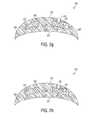
- FIG. 2 dis an illustration of positioning a structure on a first polymer layer, according to an example embodiment.
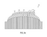
- FIG. 2 eis an illustration of a structure positioned on a first polymer layer, according to an example embodiment.
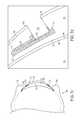
- FIG. 2 fis an illustration of formation of a second polymer layer, according to an example embodiment.
- FIG. 2 gis an illustration of soaking a partially-fabricated device in a fluid, according to an example embodiment.
- FIG. 2 his an illustration of a partially-fabricated device soaked in a fluid, according to an example embodiment.
- FIG. 3is an illustration of an eye-mountable device fabricated according to an example embodiment.
- FIG. 4is a flow chart illustrating another method according to an example embodiment.
- FIG. 5is a flow chart illustrating yet another method according to an example embodiment.
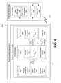
- FIG. 6is a block diagram of a system with an eye-mountable device in wireless communication with an external reader, according to an example embodiment.
- FIG. 7 ais a top view of an eye-mountable device, according to an example embodiment.
- FIG. 7 bis a side view of an eye-mountable device, according to an example embodiment.
- FIG. 7 cis a side cross-section view of the eye-mountable device of FIGS. 7 a and 7 b while mounted to a corneal surface of an eye, according to an example embodiment.
- FIG. 7 dis a side cross-section view showing the tear film layers surrounding the surfaces of the eye-mountable device mounted as shown in FIG. 7 c , according to an example embodiment.
- a body-mountable devicemay be configured to monitor health-related information based on at least one analyte detected in a fluid of a user wearing the body-mountable device.
- a body-mountable devicemay include a sensor configured to detect the at least one analyte.
- the sensorcan receive the at least one analyte through a channel in a polymer layer of the body-mountable device.
- a partially-fabricated devicemay be soaked in a fluid, such that a cross-linked polymer plug (e.g., a sacrificial cross-linked polymer plug) formed over the sensor swells out of the partially-fabricated device to leave the channel in the polymer layer.
- a cross-linked polymer plugmay maintain a stable position during formation of a polymer layer, such as a second polymer layer.
- the anterior side of the eye-mountable devicerefers to an outward-facing side of the eye-mountable device
- the posterior side of the eye-mountable devicerefers to an inward-facing side of the eye-mountable device.
- the anterior sidecorresponds to a side of the eye-mountable device that is facing outward and thus not touching the eye of the user.
- the posterior sidecorresponds to a side of the eye-mountable device that is facing inward and thus touching the eye of the user.
- FIG. 1is a flow chart illustrating a method 100 according to an example embodiment. More specifically, the method 100 involves forming a cross-linked polymer plug over a sensor located on a structure, such that the sensor is covered by the cross-linked polymer plug, as shown by block 102 . The method 100 may then involve forming a first polymer layer, as shown by block 104 . Further, the method 100 may then involve positioning the structure on the first polymer layer, as shown by block 106 .
- the method 100may then involve forming a second polymer layer over the first polymer layer and the structure to provide a partially-fabricated device in which the structure is fully enclosed by the first polymer layer, the second polymer layer, and the cross-linked polymer plug, as shown by block 108 .
- the method 100may then involve soaking the partially-fabricated device in a fluid, such that the cross-linked polymer plug swells out of the partially-fabricated device to leave a channel in the second polymer layer, as shown in block 110 .
- the method 100is described below as being carried out by a fabrication device that utilizes cast or compression molding, among other processes. It should be understood, however, that the method 100 may be carried out by a fabrication device that utilizes other methods and/or processes for forming body-mountable devices.
- the method 100is described below in a scenario where a body-mountable device comprises an eye-mountable device. It should be understood, however, that the method 100 may involve scenarios where the body-mountable device comprises other mountable devices that are mounted on or in other portions of the human body. For example, the method 100 may involve a scenario where the body-mountable device comprises a tooth-mountable device and/or a skin mountable device as described herein.
- the fabrication devicemay be used to form a cross-linked polymer plug over a sensor located on a structure, such that the sensor is covered by the cross-linked polymer plug.
- the cross-linked polymer plugcan maintain a stable position during subsequent formation steps, such as formation of a second polymer layer.
- FIGS. 2 a and 2 billustrate a fabrication device 200 that includes example equipment for forming a cross-linked polymer plug 214 over a sensor 208 located on a structure 202 .
- the structure 202has an outer diameter and a hole 204 that defines an inner diameter. And the structure 202 includes a polymer 206 , the sensor 208 , and electronics 210 .
- the structure 202may occupy a peripheral portion of an eye-mountable device, such as an eye-mountable device 300 illustrated in FIG. 3 , so as to limit interference with a user's field of view when the eye-mountable device is mounted on an eye of the user.
- the polymer 206may comprise a variety of polymeric materials, such as paralyene.
- the electronics 210is embedded in the polymer 206 , and the sensor 208 is surrounded by the polymer 206 , except for the sensor 208 being exposed by an opening 212 .
- the sensor 208 and electronics 210may be mounted on a top surface of the polymer 206 .
- the structure 202might not include the opening 212 .
- the opening 212can have a dimension of between 500 to 700 micrometers. Other dimensions are possible as well.
- the opening 212can have a square shape with rounded corners. Other shapes are possible as well, such as rectangular, circular, etc.
- the structure 202can have various sizes.
- the size of the structure 202may depend on which analyte (or analytes) an eye-mountable device is configured to detect.
- the structure 202is a substrate shaped as a ring with approximately a 1 centimeter diameter, a radial thickness of approximately 1 millimeter, and a maximum height of approximately 50 between 150 micrometers.
- other sizes of the structure 202are possible as well.
- the structure 202has a height dimension of at least 50 micrometers.
- the height of the structure 202may be at least 50 micrometers.
- this height dimensionmay correspond to a maximum height of the structure 202 .
- the maximum height of the structure 202corresponds to the height of the structure 202 at its highest point. For instance, in the example where the structure 202 comprises the sensor 208 and the electronics 210 , the height of the structure 202 may vary (and thus the structure 202 may have various height dimensions).
- the height of the structure 202may be higher at a point where the electronics 210 is mounted on the structure 202 , whereas the height may be lower at a point where there is no chip on the structure 202 .
- the maximum heightmay correspond to the point where the electronics 210 is located on the structure 202 .
- the sensor 208can be configured in a variety of ways.
- the sensor 208may comprise a pair of electrodes, such as a working electrode and a reference electrode, configured to detect one or more analytes. Other configurations of the sensor 208 are possible as well.
- the sensor 208can have a variety of thicknesses. As one example, the sensor 208 can have a thickness of 260 nanometers. Other thicknesses of the sensor 208 are possible as well.
- the electronics 210can be configured in a variety of ways. As one example, the electronics 210 can comprise a chip including one or more logic elements configured to operate the sensor 208 . Other configurations of the electronics 210 are possible as well.
- forming the cross-linked polymer plug 214 over the sensor 208 located on the structure 202can include injecting a polymerizable mixture 216 over the sensor 208 and curing the polymerizable mixture 216 .
- the fabrication device 200may be configured to inject the polymerizable mixture 216 over the sensor 208 .
- the fabrication device 200can inject the polymerizable mixture 216 into the opening 212 .
- the cross-linked polymer plug 214might take the shape of or be similar in shape to the opening 212 .
- the polymerizable mixture 216can be injected into the opening 212 , such that a portion of the polymerizable mixture 216 is located over the opening 212 .
- the maximum height of the structure 202may correspond to the point where the cross-linked polymer plug 214 is located on the structure 202 .
- the fabrication device 200may include an injector, such as a microcapillary injector, that injects the polymerizable mixture 216 over the sensor 208 .
- an injectorsuch as a microcapillary injector
- the injectorcan inject a predetermined quantity of the polymerizable mixture 216 over the sensor 208 before subsequent formation steps, such as cross-linking with heat or light.
- the injectormay be NanojectTM sold by Debiotech.
- Curinginvolves initiating the polymerization reaction of the monomers and/or macromonomers in the polymerizable mixture 216 , and results in the formation of the cross-linked polymer plug 214 .
- Curingmay be, for example, brought about by chemical additives, ultraviolet radiation, electron beam, and/or heat.
- the polymerizable mixture 216can be a light-curable
- the fabrication device 200may be configured to cure the light-curable polymerizable mixture using light, such as ultraviolet light or visible light.
- the fabrication device 200may be configured to cure different polymerizable mixtures differently than other polymerizable mixtures (e.g., a first polymerizable mixture may be cured more than a second polymerizable mixture). Further, in addition to light curing, other methods of curing are possible as well, such as chemical additives and/or heat.
- forming the cross-linked polymer plug 214 over the sensor 208 located on the structure 202can include spin coating the polymerizable mixture 216 over the sensor 208 and photopatterning the polymerizable mixture 216 .
- the fabrication devicemay be configured to spin coat the polymerizable mixture 216 over the sensor 208 .
- the fabrication device 200can spin coat the polymerizable mixture 216 into the opening 212 .
- the cross-linked polymer plug 214might take the shape of or be similar in shape to the opening 212 .
- the polymerizable mixture 216can be spin coated into the opening 212 , such that a portion of the polymerizable mixture 216 is located over the opening 212 .
- the maximum height of the structure 202may correspond to the point where the cross-linked polymer plug 214 is located on the structure 202 .
- the fabrication device 200may include a spin coating machine, such as a spin coater (e.g., ACE-1020 Series), that spin coats the polymerizable mixture 216 over the sensor 208 .
- a spin coating machinesuch as a spin coater (e.g., ACE-1020 Series), that spin coats the polymerizable mixture 216 over the sensor 208 .
- the fabrication device 200may be configured to photopattern the polymerizable mixture 216 .
- the cross-linked polymer plug 214could take various different forms in various different embodiments.
- the cross-linked polymer plug 214includes a cross-linked polymer capable of increasing in volume when contacted with a fluid.
- the cross-linked polymer plug 214can be a hydrophilic polymer that swells upon contact with an aqueous solution, such as a hydrogel.
- the cross-linked polymer plug 214can be compliant, such that the cross-linked polymer plug 214 may deform during subsequent formation steps, such as formation of a second polymer layer.
- the cross-linked polymer plug 214can be formulated for specific properties, such as, maintaining form during the formation of one or more polymer layers, such as a first or second polymer layer.
- Polymer propertiescan also be chosen for compatibility with one or more fluids used in formation steps, such as swelling when treated with a fluid used in a soaking step.
- the cross-linked polymer plug 214includes:
- crosslinks between second methacrylate-derived units in different backbone chainsare crosslinks between second methacrylate-derived units in different backbone chains.
- the side chain of the first methacrylate-derived monomerscan be chosen from a variety of moieties.
- the side chaincan be covalently bound through the carboxylate of the methacrylate monomeric unit, optionally through a linker.
- the crosslinks, or groups through which the second methacrylate-derived units of different backbone chains are connected to each other,are discussed in greater detail below.
- the backbone chains of the cross-linked polymer plug 214include one or more additional first methacrylate-derived units, each having a side chain.
- the side chain of the additional unitsare different than the side chains of the first methacrylate-derived monomeric units, providing a crosslinked copolymer plug.
- the backbone chains of the cross-linked polymer plug 214include methacrylate-derived monomeric units derived from a methacrylated polymer (i.e., a “methacrylate macromonomer”).
- methacrylate macromonomersare derived from the reaction of a polymer having one or more reactive groups, with a methacrylate monomer having one or more complimentarily reactive groups (i.e., a methacrylation agent).
- the polymercan have nucleophilic groups, such as hydroxyl, carboxylate, amino or thiol groups, and the methacrylation agent can have an electrophilic group, for example, an ester, isocyanate or an epoxide.
- the methacrylation agentcan be nucleophilic, and the polymer can have an electrophilic group.
- methacrylate macromonomersinclude, but are not limited to, methacrylated poly(vinylpyridine), methacrylated poly(allylamine), methacrylated chitosan and methacrylated hyaluronic acid.
- methacrylate-derived macromonmeric unitsThe units derived from methacrylated macromonomers will herein be referred to as “methacrylate-derived macromonmeric units”.
- methacrylated macromonomershave multiple methacrylate groups that can polymerize upon curing of the polymerizable mixture 216 .
- the presence of one or more methacrylated macromonomers in the polymerizable mixture 216can provide a cross-linked polymer plug 214 in which one or more backbone chains are connected through a macromonomer side chain as well as through the crosslinks between the second methacrylate-derived units in different backbone chains.
- the cross-linked polymer plug 214includes methacrylate monomeric units covalently bound to side chains include one or more alkylene oxide units.
- the alkylene oxide unitscan be derived from ethylene oxide, propylene oxide or butylene oxide, and can be a combination of two or three different alkylene oxide units.
- the alkene oxide unitsform a poly(alkylene oxide) such as poly(ethylene glycol) or polypropylene glycol).
- the cross-linked polymer plug 214can include first methacrylate-derived monomeric units having the formula (I):
- xis such that the number average molecular weight (M n ) of the corresponding monomeric unit is about 100 to about 10,000. In some embodiments, x can be an average number from about 1 to about 250.
- the cross-linked polymer plug 214includes methacrylate monomeric units covalently bound to a side chain containing one or more nitrogen moieties.
- the nitrogen moietycan be part of a heterocycle, heteroaromatic, mono-, di-, and tri-alkyl amine, allyl amine, benzyl amine, amino saccharide, amino polysaccharide, and derivatives thereof.
- cross-linked polymer plug 214can includes monomeric units having the formula (II):
- the cross-linked polymer plug 214can include methacrylate monomeric units covalently bound to a side chain having a carboxylic acid group. In some instances, the cross-linked polymer plug 214 includes monomeric units having the formula (III):
- ncan be 0, 1, 2, 3, 4, 5, 6, 7, 8, 9 or 10.
- the cross-linked polymer plug 214includes methacrylate-derived macromonomeric units having the formula (IV):
- Ais a repeating unit monomeric unit
- Xis a reactive group
- X′is X with a positive charge or one less hydrogen atom
- Lis a linker
- the ratio of m:m′is about 2:1 to about 50:1. In certain embodiments, the ratio is about 5:1 to about 15:1, and in some instances, about 9:1.
- Acan be selected from a variety of monomeric units, such as saccharides and ethylenically unsaturated units, including, but not limited to acryl-, methacryl, ethacryl, itaconyl, styryl, acrylamidyl, methacrylamidyl, vinyl and allyl units.
- the reactive group (X)includes a nucleophilic moiety, such as a hydroxyl, amino or thiol group.
- Amino groupscan include primary, secondary and tertiary amines, and nitrogen-containing heterocycles.
- the methacrylate-derived macromonomeric unitscan be derived from allylamine and have the formula (IVa):
- the methacrylate-derived macromonomeric unitscan be derived from vinylpyridine and have the formula (IVb):
- the reactive group (X)includes an electrophilic moiety, such as an ester, isocyanate or an epoxide, and undergoes methacrylation with a methacrylation agent having one or more nucleophilic moieties.
- Nucleophilic moietiesinclude hydroxyl, amino and thiol groups.
- Amino groupscan include primary, secondary and tertiary amines, and nitrogen-containing heterocycles.
- the cross-linked polymer plug 214includes macromonomeric units derived from methacrylated polysaccharides.
- the polysaccharidescan have the general formula of C x (H 2 O) y where x can be between about 200 and about 2500.
- the polysaccharidescan also include glycosaminoglycans and polysaccharides modified to contain one or more thiol moieties.
- the cross-linked polymer plug 214can having the formula (IVc):
- Lis a linker that can be derived from any group capable of undergoing chemical reaction with one or more reactive groups (X) of a polymer to form a covalent bond.
- the linkercan be derived from a group having a nucleophilic or electrophilic moiety, such as hydroxyl, thiol and amino groups, carboxylate, epoxide or isocyanate groups.
- the Lis derived from a group having one or more epoxide moieties. Chemical reaction of the epoxide with the reactive groups of a polymer can proceed through nucleophilic attack of the polymer at the electrophilic epoxide carbon atom, providing a L group having or more secondary alcohol moieties.
- the first methacrylate-derived unitscan have the structure of formula (IVd):
- v1, 2, 3, 4, 5, 6, 7, 8, 9 or 10.
- the Lis derived from a group having one or more isocyanate moieties. Chemical reaction of the isocyanate with the reactive groups of a polymer can provide an L group having or more urea moieties.
- the first methacrylate-derived unitscan have the structure of formula (IVe):
- yis 1, 2, 3, 4, 5, 6, 7, 8, 9 or 10.
- the methacrylation agentcan be 2-isocyanatoethyl methacrylate or glycidyl methacrylate.
- crosslinks of cross-linked polymer plug 214are groups through which the second methacrylate-derived units of different backbone chains are connected to each other, and are represented by “W” in formula (V):
- Zis independently —O—, —NR′— or —S—, and W is a hydrophilic group.
- the crosslinksare hydrophilic.
- the crosslinkscan be soluble in water or a water-miscible solvent, such as an alcohol.
- the crosslinkscan have one or more heteroatoms, for example, nitrogen, oxygen or sulfur atoms.
- the crosslinkshave one or more hydroxy groups.
- the crosslinksinclude one or more alkylene oxide units.
- the alkylene oxide unitscan be in the form of a polymer, such as poly(ethylene glycol), poly(propylene glycol), poly(butylene oxide) or a mixture thereof, and can be a copolymer including a combination of two or three different alkylene oxide units.
- the poly(alkylene oxide) of the crosslinksis a block copolymer including blocks of two or three different poly(alkylene oxide) polymers.
- the poly(alkylene oxide)is a block copolymer of poly(ethylene glycol) and poly(propylene glycol).
- the crosslinksinclude poly(ethylene glycol) (PEG).
- the crosslinksinclude one or more ethylene oxide units.
- the crosslinkse.g., A in formula (V) above
- w0, 1, 2, 3, 4, 5, 6, 7, 8, 9 or 10.
- wis an average value of from about 2 to about 250.
- w in the crosslinks of formula (Va)is such that the number average molecular weight (M n ) of the PEG portion (within the brackets in formula (Va)) of the crosslinks is about 100 to about 10,000.
- M nnumber average molecular weight
- wcan be selected such that the M n of the PEG portion of the crosslinks falls within a range in Table 1:
- the crosslinksare derived from di(ethylene glycol) dimethacrylate, i.e., compounds of formula (V) or (Va) where Z is —O— and w is 1.
- the side chain of the cross-linked polymer plug 214can be formulated so that the plug does not swell during the formation of one or more polymer layers, such as a first or second polymer layer.
- a cross-linked polymer plug 214 comprising poly(ethylene glycol) side chainsmay swell prematurely.
- a cross-linked polymer plug 214 comprising nitrogen-containing side chainscan be used. The basicity of the nitrogen moieties will resist water absorption (and thus swelling) under basic conditions.
- the cross-linked polymer plug 214can then be treated under acidic conditions (pH less than 7) to induce swelling when desired.
- a cross-linked polymer plug 214comprising carboxylic acid groups can be used.
- the acidity of the carboxylic acid groupwill resist water absorption under acidic conditions, but will swell when treated under basic conditions (pH greater than 7).
- the cross-linked polymer plug 214can have a variety of thicknesses. As one example, the cross-linked polymer plug 214 can have a thickness of up to 100 micrometers. Other thicknesses are possible as well. In the illustrated example, when the cross-linked polymer plug 214 is formed over the sensor 208 , the cross-linked polymer plug 214 may have a height dimension that is greater than the height dimension of the electronics 210 located on the structure 202 .
- the formation of the cross-linked polymer plug 214includes depositing the precursors of the cross-linked polymer (polymerizable mixture 216 ) on the sensor 208 , and initiating polymerization (curing) so that the sensor 208 is covered by the resulting cross-linked polymer plug 214 .
- the formation of the cross-linked polymer plug 214includes:
- the polymerizable mixturecan be formed in an aqueous medium, alcoholic medium, or mixture thereof.
- the aqueous mediumcan include a buffered aqueous solution, such as, for example, a solution containing citric acid, acetic acid, borate, carbonate, bicarbonate, 4-2-hydroxyethyl-1-piperazineethanesulfonic acid (HEPES), 3- ⁇ [tris(hydroxymethyl)methyl]amino ⁇ propanesulfonic acid (TAPS), N,N-bis(2-hydroxyethyl)glycine (Bicine), tris(hydroxymethyl)methylamine (Tris), N-tris(hydroxymethyl)methylglycine (Tricine), 3-[N-Tris(hydroxymethyl)methylamino]-2-hydroxypropanesulfonic Acid (TAPSO), 2- ⁇ [tris(hydroxymethyl)methyl]amino ⁇ ethanesulfonic acid (TES), 3-(N-morpholino)propanesulfonic acid (MOPS), piperazine
- the methacrylate monomerare selected to provide the first methacrylate-derived monomeric units of the cross-linked polymer plug 214 .
- the methacrylate monomerhas a side chain that includes one or more alkylene oxide units.
- the monomercan have the formula (VI):
- xis selected to provide the first methacrylate-derived monomeric unit of the cross-linked polymer plug 214 , as described herein.
- the cross-linked polymer plug 214can be formed with one or more monomers suitable for the resulting cross-linked polymer plug 214 to be a hydrogel.
- the formation of the cross-linked polymer plug 214includes a monomer covalently bound to a side chain containing one or more nitrogen moieties.
- the nitrogen moietycan be part of a heterocycle, heteroaromatic, mono-, di-, and tri-alkyl amine, allylamine, benzylamine, amino saccharide, amino polysaccharide, and derivatives thereof.
- the monomercan have the formula (VII):
- the methacrylate monomerincludes a side chain having a carboxylic acid group.
- the monomercan have the formula (VIII):
- nis selected to provide the first methacrylate-derived monomeric unit of the cross-linked polymer plug 214 , as described herein.
- methacrylate monomeris a methacrylate macromonomer derived from the methacrylation of a polymer such as poly(vinyl amine), poly(vinyl pyridine), chitosan or hyaluronic acid.
- a polymersuch as poly(vinyl amine), poly(vinyl pyridine), chitosan or hyaluronic acid.
- the methacrylate monomercan be a methacrylate macromonomer having the formula (IX):
- A, X, X′, L, m and m′are selected to provide the first methacrylate-derived monomeric unit of the cross-linked polymer plug 214 , as described herein.
- the methacrylate macromonomerhas the formula (IXa):
- L, m and m′are selected to provide the first methacrylate-derived monomeric unit of the cross-linked polymer plug 214 , as described herein.
- the methacrylate macromonomerhas the formula (IXb):
- L, m and m′are selected to provide the first methacrylate-derived monomeric unit of the cross-linked polymer plug 214 , as described herein.
- the methacrylate macromonomerhas the formula (IXc):
- sugar unit, X, X′, L, m and m′are selected to provide the first methacrylate-derived monomeric unit of the cross-linked polymer plug 214 , as described herein.
- the methacrylate macromonomerhas the formula (IXd):
- A, X, X′, v, m and m′are selected to provide the first methacrylate-derived monomeric unit of the cross-linked polymer plug 214 , as described herein.
- the methacrylate macromonomerhas the formula (IXe):
- A, X, X′, y, m and m′are selected to provide the first methacrylate-derived monomeric unit of the cross-linked polymer plug 214 , as described herein.
- the polymerizable mixture 216includes more than one methacrylate monomer, where each monomer has a different side chain.
- the depositing and curing of the polymerizable mixture 216can provide a cross-linked copolymer plug that is a copolymer having methacrylate backbone chains with two or more different side chains.
- the crosslinking agentis a dimethacrylate monomer having two terminal methacrylate groups tethered by a hydrophilic linker.
- the hydrophilic linkeris selected to provide the crosslinks between the second methacrylate-derived units in different backbone chains of the cross-linked polymer plug 214 , as described herein.
- the hydrophilic linker of the crosslinking agentincludes one or more alkylene oxide units.
- the alkylene oxide unitscan be in the form of a polymer, such as poly(ethylene glycol), polypropylene glycol), poly(butylene oxide) or a mixture thereof, and can be a copolymer including a combination of two or three different alkylene oxide units.
- the cross-linking agentcan have the formula (X):
- wis selected to provide the crosslinks of the cross-linked polymer plug 214 , as described herein.
- the method of curing (i.e., initiating polymerization) the polymerizable mixture 216can be dictated by the initiator used, which can be chosen for the desired initiation efficiency and/or initiation conditions. Initiators can be activated by a wide range of physical and chemical conditions, such as thermal decomposition, photolysis, redox reactions, persulfates, ionizing radiation, electrolysis and sonication.
- the polymerizable mixture 216can be cured with ultraviolet (UV) light.
- the polymerizable mixture 216can be spin-coated onto the sensor.
- the polymerizable mixture 216can be photopatterned on the sensor.
- cross-linked polymer plug 214is formed by spin-coating a 17:1:1:1 mixture of PEG950MA (polyethylene glycol methacrylate with an Mn of 950), PEG600DMA (polyethylene glycol dimethacrylate with an Mn of 600), Darucur 1173 (initiator) and Red Dye onto a silicon wafer and radiating the area over the sensor 208 .
- PEG950MApolyethylene glycol methacrylate with an Mn of 950
- PEG600DMApolyethylene glycol dimethacrylate with an Mn of 600
- Darucur 1173initiator
- Red DyeRed Dye
- a 30% solution of Poly(4-vinyl pyridine) [mol. wt. 160K) functionalized with methacrylate groups in EtOH containing 1 wt % Darocur 1173is spun on a silicone wafer and the area over the sensor is irradiated. The non-polymerized formulation is rinsed from the wafer after photopolymerization.
- Ethylenically unsaturated monomers and macromonomersmay be either acrylic- or vinyl-containing.
- Vinyl-containing monomerscontain the vinyl grouping (CH 2 ⁇ CH—), and are generally highly reactive.
- Acrylic-containing monomersare represented by the formula:
- suitable polymerizable groupsmay include acrylic-, ethacrylic-, itaconic-, styryl-, acrylamido-, methacrylamido- and vinyl-containing groups such as the allyl group.
- crosslinked polymeric networksby the polymerization of ethylenically unsaturated monomers and macromonomers
- additional chemistrieswill be known to one of ordinary skill in the art to from such networks.
- epoxy chemistryin which multifunctional amines and multifunctional epoxy compounds are mixed together and cured, can be used to form cross-linked polymer networks.
- urethane chemistrymay be used, in which multifunctional isocyanates are mixed with multifunctional alcohols and cured to provide cross-linked polymer networks.
- Other chemistries for the formation of cross-linked polymer networksexist, and will be well known to those of ordinary skill in the art.
- the fabrication devicemay be used to form a first polymer layer.
- the fabrication devicemay include molding pieces, such as molding pieces that are suitable for cast molding.
- FIG. 2 cillustrates the fabrication device 200 includes molding pieces that may be used to form the first polymer layer.
- FIG. 2 cillustrates the fabrication device 200 including a first molding piece 218 and a second molding piece 220 .
- the first molding piece 218 and the second molding piece 220may define a first cavity.
- the second molding piece 220may be filled with a polymer material 222 , and the polymer material 222 may be compressed into a first polymer layer 224 by the first molding piece 218 .
- the fabrication device 200may cure the first polymer layer 224 .
- the polymer material 222can be a light-curable polymer material, and the fabrication device 200 may be configured to cure the light-curable polymer material using light, such as ultraviolet light or visible light.
- the first polymer layer 224may be cured to a partially-cured state. In such an example, this may involve curing the material to a partially-cured state that is approximately 50-75% of a fully cured state. Other partially-cured states are possible as well.
- the first polymer layer 224may have a tackiness that facilitates adhesion thereto.
- the tackinessmay ensure that a structure placed on the first polymer layer 224 remains securely fixed in a given location during subsequent formation steps.
- the tackiness exhibited by the partially-cured first polymer layer 224may be different for different polymers. Accordingly, the fabrication device 200 may be configured to cure different polymer materials differently than other polymer materials (e.g., a first polymer material may be cured more than a second polymer material). Further, in addition to light curing, other methods of curing are possible as well, such as chemical additives and/or heat. Yet still further, in other example embodiments, the first polymer layer 224 may be completely cured. Alternatively, the fabrication device 200 may bypass curing the first polymer layer 224 at this stage.
- the first molding piece 218 and the second molding piece 220may be configured to achieve a given desired thickness of the first polymer layer 224 .
- the first polymer layer 224can have a thickness of less than 150 micrometers.
- the first molding piece 218 and the second molding piece 220can be designed so as to allow for a layer having less than a 150 micrometer thickness between the two cavities. As such, when the first molding piece 218 and the second molding piece 220 are pressed together during the formation of the first polymer layer 224 , the resulting polymer layer 224 will have a thickness of less than 150 micrometers.
- the thickness of the first polymer layer 224can be selected based on a particular analyte or analytes an eye-mountable device is configured to detect.
- an optimal thickness for a first analytemay be 10 micrometers, while an optimal thickness for a second analyte may be 25 micrometers. Other examples are possible as well.
- the polymer material 222can be any material that can form an eye-compatible polymer layer.
- the polymer material 222may be a formulation containing polymerizable monomers, such as hydrogels, silicone hydrogels, silicone elastomers, and rigid gas permeable materials.
- the polymer material 222may form a transparent or substantially transparent polymer layer.
- the use of the polymer material 222may result in an eye-mountable device through which the wearer can see when mounted on the wearer's eye.
- the polymer material 222can be a hydrogel material, such as silicone hydrogel.
- hydrogel materialsare commonly used in contact-lens technology and are well-suited for eye-mountable devices. Other materials are possible as well.
- the structure 202can be more rigid than the first polymer layer 224 .
- first molding piece 218 and/or the second molding piece 220can be configured so as to allow sufficient pinch off to provide for suitable edges for an eye-mountable device.
- the first polymer layer 224defines a posterior side 226 of an eye-mountable device. That is, the first polymer layer 224 defines an outer edge of the eye-mountable device. When mounted on an eye of a user, the posterior side 226 of the eye-mountable device defined by the first polymer layer 224 corresponds to a side of the device touching the eye of the user.
- the first molding piece 218may be shaped so as to define a shape of the posterior side 226 . For example, a curvature of the posterior side 226 may be defined by the first molding piece 218 .
- the first polymer layer 224can further comprise an alignment feature 228 .
- the alignment feature 228can comprise an asymmetric peg.
- the asymmetric pegcan be a variety of shapes.
- the asymmetric pegcan have a star-shaped or cross-shaped cross section. Other shapes of the asymmetric peg are possible as well.
- FIG. 2 cillustrates forming the first polymer layer 224 through cast molding
- the first polymer layer 224may be formed via injection molding.
- injection moldingrather than polymer material being compressed between molding pieces, molding material may be heated and injected or otherwise forced into a molding piece or pieces. The injected molding material may then cool and harden to the configuration of the molding piece or pieces.
- the first polymer layer 224may be formed via spin casting.
- the fabrication devicemay form a first polymer layer of a precise thickness.
- a spin-casting moldmay be spun along its central access at a set speed, and the polymer may be introduced to the mold as the mold is spinning in order to form a first polymer layer.
- the final thickness of the first polymer layermay be influenced by various factors, including but not limited to the spin-casting mold, the amount of polymer introduced to the spin-casting mold, properties of the polymer such as viscosity, and/or the speed at which the spin-casting mold is rotated. These factors may be varied in order to result in a first polymer layer of a well-defined thickness.
- FIGS. 2 d and 2 eillustrate an example in which the structure 202 is positioned on the first polymer layer 224 .
- the fabrication device 200may separate the first molding piece 218 from the second molding piece 220 .
- the first polymer layer 224may stick to a side of the first molding piece 218 .
- the first polymer layer 224 and/or the first molding piece 218can be surface treated, such that the first polymer layer 224 sticks to the side of the first molding piece 218 .
- the second molding piece 220can be surface treated, such that the first polymer layer 224 sticks to the side of the first molding piece 218 .
- positioning the structure 202 on the first polymer layer 224can include aligning the structure 202 with the alignment feature 228 .
- the hole 204 in the structure 202has an asymmetric inner diameter and the alignment feature 228 includes an asymmetric peg such that the hole 204 receives the alignment feature 228 in only a predetermined rotational orientation.
- other ways of providing a predetermined rotational orientation of the structure 202 by alignment with the alignment feature 228are also possible.
- the fabrication device 200can include a positioning apparatus (not shown), such as a robotic system, configured to position the structure 202 on the first polymer layer 224 in a predetermined rotational orientation.
- the positioning apparatusmay (i) pick up the structure 202 (e.g., via suction), (ii) position the structure 202 above the first polymer layer 224 , and then (iii) lower the structure 202 toward the first polymer layer 224 .
- the positioning apparatusmay then release the structure 202 (e.g., by releasing the suction).
- the first polymer layer 224might not include the alignment feature 228 .
- the positioning apparatusmay bend the structure 202 .
- the positioning apparatusmay bend the structure 202 by applying a force and/or a torque to one or more portions of the structure 202 .
- the positioning apparatusmay further include a vision system configured to assist with positioning the structure 202 on the first polymer layer 224 .
- a vision systemmay facilitate guiding the structure 202 to a precise location on the first polymer layer 224 .
- the vision systemcan be appropriate for situations in which one or more production specifications for an eye-mountable device, such the eye-mountable device 300 , have requirements with very low tolerances related to the positioning of a sensor, such as the sensor 208 , within the eye-mountable device.
- an eye-mountable devicesuch as the eye-mountable device 300
- movement of the structure 202 during subsequent formation stepssuch as formation of a second polymer layer
- movement of the structure 202 during filling a mold piece with a polymer material to form the second polymer layer and/or curing the second polymer layercan result in improper placement of the structure 202 relative to the surrounding polymer layers.
- an adhesiveis applied to the structure 202 and/or the first polymer layer 224 before the structure 202 is placed on the first polymer layer 224 .
- the applied adhesivemay facilitate adhesion of the structure 202 to the first polymer layer 224 .
- a small amount of adhesivemay be applied to a cured first polymer layer 224 , and the structure 202 may be positioned on the small amount of adhesive such that the structure 202 adheres to the first polymer layer 224 .
- a small amount of adhesivemay be applied to the structure 202 , and the structure 202 may then be placed on the first polymer layer 224 (e.g., a cured first polymer layer) such that the structure 202 adheres to the first polymer layer 224 .
- the structure 202may remain adhered to the first polymer layer 224 in a secure location during subsequent formation steps.
- the first polymer layer 224 in a partially-cured statemay have a tackiness that facilitates adhesion thereto.
- the structure 202may remain adhered to the first polymer layer 224 in a secure location during subsequent formation steps.
- an eye-mountable devicein accordance with an example embodiment allows for such repeatable and precise positioning.
- FIG. 2 eillustrates the structure 202 positioned on the first polymer layer 224 .
- the sensor 208may be mounted at a particular angle along a circumference of the first polymer layer 224 .
- the sensor 208may be placed at a precise location in an XYZ plane on the first polymer layer 224 .
- the sensor 208may rest at a 6 o'clock position of the first polymer layer 224 .
- the sensor 208may rest at a 12 o'clock position of the first polymer layer 224 .
- the fabrication devicemay form a second polymer layer over the first polymer and the structure to provide a partially-fabricated device.
- FIG. 2 fillustrates the fabrication device 200 including molding pieces that may be used to form the second polymer layer.
- FIG. 2 fillustrates a third molding piece 230 .
- the first molding piece 218 and the third molding piece 230may define a second cavity.
- FIG. 2 gillustrates a partially-fabricated device (or a device) 240 .
- the first molding piece 218which already holds the first polymer layer 224 to which the structure 202 is mounted (as illustrated in FIG. 2 e ), may be filled with a polymer material 232 .
- the polymer material 232may be formed into a second polymer layer 234 by compression between the first molding piece 218 and the third molding piece 230 .
- the cross-linked polymer plug 214may block the second polymer layer 234 from molding over the sensor 208 .
- the second polymer layer 234may mold over the structure 202 , such that the structure 202 is fully enclosed by the first polymer layer 224 , the second polymer layer 234 , and the cross-linked polymer plug 214 .
- the third molding piece 230may contact the cross-linked polymer plug 214 during formation of the second polymer layer 234 .
- the cross-linked polymer plug 214can provide a seal during formation of the second polymer layer 234 .
- the cross-linked polymermay be complaint.
- the cross-linked polymer plug 214can deform.
- the fabrication device 200may cure the second polymer layer 234 .
- the second polymer layer 234can be cured like the first polymer layer 224 .
- the second polymer layer 234may be cured by different techniques than the first polymer layer 224 .
- the second polymer layer 234can be cured by any of the techniques mentioned herein.
- the fabrication device 200may cure the first polymer layer 224 at this stage.
- FIG. 3illustrates the eye-mountable device 300 .
- FIG. 3illustrates the eye-mountable device 300 includes a transparent polymer 302 .
- the transparent polymer 302can be arranged like the first polymer layer 224 and the second polymer layer 234 .
- the fabrication device 200may further comprise one or more alignment pins (not shown), such as a plurality of dowel pins, for aligning the third molding piece 230 and the first molding piece 218 .
- the one or more alignment pinscan assist in forming the second polymer layer 234 by aligning the third molding piece 230 with the first molding piece 218 .
- the first molding piece 218 and the third molding piece 230may be configured to achieve a given desired thickness of a layer formed between the two cavities.
- the first molding piece 218 and the third molding piece 230may be designed so as to define a thickness of the second polymer layer 234 .
- the first molding piece 218 and the third molding piece 230may be designed so as to define a final thickness of an eye-mountable device, such as the eye-mountable device 300 .
- the first molding piece 218 and the third molding piece 230can be designed so as to allow for a layer having a given desired thickness between the two pieces (in addition to a thickness of the first polymer 224 ). As such, when the first molding piece 218 and the third molding piece 230 are pressed together during formation of a layer, the resulting layer will have the given desired thickness.
- the second polymer layer 234has a thickness of greater than 50 micrometers. However, in other examples, the second polymer layer 234 can have a thickness between 50 and 300 micrometers, such as 130 micrometers. It should be understood that since the second polymer layer 234 molds over the structure 202 except for the cross-linked polymer plug 214 , the second polymer layer 234 may not have a uniform thickness. For instance, the thickness of the second polymer layer 234 above the electronics 210 may be less than the thickness of the second polymer layer 234 that is not touching the electronics 210 .
- the thickness of the second polymer layer 234can be selected based on a particular analyte or analytes that the eye-mountable device, such as the eye-mountable device 300 , is configured to detect.
- a particular analyte or analytes that the eye-mountable device, such as the eye-mountable device 300is configured to detect.
- an optimal thickness for a first analytemay be 10 micrometers, while an optimal thickness for a second analyte may be 25 micrometers. Other examples are possible as well.
- the second polymer layer 234can be composed of the same polymer material as the first polymer layer 224 . However, in other examples, the second polymer layer 234 can be composed of a different polymer material than the first polymer layer 224 .
- the second polymer layer 234can be any one of the polymer materials mentioned herein.
- the structure 202can be more rigid than the second polymer layer 234 .
- the second polymer layer 234defines an anterior side 236 of an eye-mountable device. That is, the second polymer layer 234 defines an outer edge of the eye-mountable device.
- the anterior side 236 of the eye-mountable device defined by the second polymer layer 234corresponds to the side of the device that is not touching the eye of the user.
- the third molding piece 230may be shaped so as to define a shape of the anterior side 236 . For example, a curvature of the anterior side 236 may be defined by the third molding piece 230 .
- FIGS. 2 g and 2 hillustrate the fabrication device 200 soaking the partially-fabricated device.
- FIG. 2 g and FIG. 2 hillustrate the fabrication device 200 soaking the partially-fabricated device 240 , such that the cross-linked polymer plug 214 swells out of the partially-fabricated device 240 to leave a channel 242 in the second polymer layer 234 .
- FIG. 2 g and FIG. 2 hillustrate the fabrication device 200 soaking the partially-fabricated device 240 , such that the cross-linked polymer plug 214 swells out of the partially-fabricated device 240 to leave a channel 242 in the second polymer layer 234 .
- the partially-fabricated device 240includes the structure 202 , the sensor 208 , the electronics 210 , the cross-linked polymer plug 214 , the posterior side 226 , the anterior side 236 , and a transparent polymer 238 .
- the transparent polymer 238includes the first polymer layer 224 and the second polymer layer 234 .
- the fabrication device 200may separate the first molding piece 218 from the third molding piece 230 .
- the partially-fabricated device 240may stick to a side of the first molding piece 218 .
- the first molding piece 218can hold the partially-fabricated device 240 .
- the first polymer layer 224 and/or the first molding piece 218can be surface treated, such that the partially-fabricated device 240 sticks to the side of the first molding piece 218 .
- the third molding piece 230 and/or the partially-fabricated device 240can be surface treated, such that the partially-fabricated device 240 sticks to the side of the first molding piece 218 .
- the partially-fabricated device 240is removed from the first molding piece 218 .
- removing the partially-fabricated device 240 from the first mold piece 218can include the fabrication device 200 removing the surface treatment of the partially-fabricated device 240 and/or the first molding piece 218 .
- the partially-fabricated device 240is soaked in a fluid, such that the cross-linked polymer plug 214 swells out of the partially-fabricated device 240 to leave the channel 242 in the second polymer layer 234 .
- the fabrication device 200can soak the partially-fabricated device 238 in a fluid.
- the fluidcould take various different forms in various different embodiments.
- the fluidmay selected based on the material of the cross-linked polymer plug 214 , the material of the first polymer layer 224 , the material of the second polymer layer 234 , and/or the material of the polymer 206 .
- the fluidcan include one or more fluids selected from the group consisting of an aqueous solution and an organic solvent.
- the aqueous solutioncan be pure water, acidic, basic or buffered, such as phosphate buffered saline.
- the organic solventcan be a water-miscible solvent, such as tetrahyrofuran (THF), acetone or acetonitrile, a chlorinated sovent, such as dichloromethane or chloroform, or other solvent such as ethyl acetate or hexanes.
- the fluidis a homogeneous mixture of an aqueous solution and an organic solvent, such as water/THF or water/acetonitrile.
- the fluidis acidic.
- the fluidincludes an organic or inorganic acid in an organic solvent or aqueous solution.
- the acidic solutionhas a pH between 1 and 3. In other instances, the acidic solution has a pH between 3 and 5, while in other instances the acidic solution has a pH between 5 and 7. In some embodiments, the acidic solution has a pH less than 1.
- the fluidis basic.
- the fluidincludes an organic or inorganic base in an organic solvent or aqueous solution.
- the basic solutionhas a pH between 7 and 9. In other instances, the basic solution has a pH between 9 and 11, while in other instances the basic solution has a pH between 11 and 14. In some embodiments, the basic solution has a pH greater than 14.
- FIG. 3illustrates the eye-mountable device 300 fabricated according to an example embodiment.
- FIG. 3illustrates an anterior side 306 including a channel 318 .
- a structure 308is embedded in the transparent polymer 302 .
- the structure 308has an outer diameter 310 and inner diameter 312 and includes a sensor 314 configured to detect an analyte and electronics 316 .
- the eye-mountable device 300includes a posterior side 304 and the anterior side 306 .
- the structure 308may take the form of or be similar in form to the structure 202
- the sensor 314may take the form of or be similar in form to the sensor 208
- the electronics 316may take the form of or be similar in form to the electronics 210 .
- the inner diameter 312can be asymmetric and define a rotational orientation of the structure 308 relative to the channel 318 , such that the sensor 314 is configured to receive the analyte via the channel 318 .
- the structure 308is fully enclosed by the transparent polymer 302 , except for the sensor 314 being exposed by the channel 318 .
- one or more dimensions of the channel 318may be based on one or more dimensions of the sensor 314 and/or the electronics 316 .
- a width of the channel 318can be based on a width of the sensor 314 .
- a height of the channel 318can be based on a height of the electronics 316 .
- body-mountable devicehas been described as comprising the eye-mountable device 300
- the body-mountable devicecould comprise other mountable devices that are mounted on or in other portions of the human body.
- the body-mountable devicemay comprise a tooth-mountable device.
- the tooth-mountable devicemay take the form of or be similar in form to the eye-mountable device 300 .
- the tooth-mountable devicemay include polymer layers and/or a transparent polymer that are the same or similar to any of the polymer layers and/or the transparent polymers described herein and a structure that is the same or similar to any of the structures described herein.
- the tooth-mountable devicemay be configured to detect at least one analyte in a fluid (e.g., saliva) of a user wearing the tooth-mountable device.
- a fluide.g., saliva
- the body-mountable devicemay comprise a skin-mountable device.
- the skin-mountable devicemay take the form of or be similar in form to the eye-mountable device 300 .
- the tooth-mountable devicemay include polymer layers and/or a transparent polymer that are the same or similar to any of the polymer layers and/or the transparent polymers described herein and a structure that is the same or similar to any of the structures described herein.
- the skin-mountable devicemay be configured to detect at least one analyte in a fluid (e.g., perspiration, blood, etc.) of a user wearing the skin-mountable device.
- a fluide.g., perspiration, blood, etc.
- some embodimentsmay include privacy controls which may be automatically implemented or controlled by the wearer of a body-mountable device. For example, where a wearer's collected physiological parameter data and health state data are uploaded to a cloud computing network for trend analysis by a clinician, the data may be treated in one or more ways before it is stored or used, so that personally identifiable information is removed. For example, a user's identity may be treated so that no personally identifiable information can be determined for the user, or a user's geographic location may be generalized where location information is obtained (such as to a city, ZIP code, or state level), so that a particular location of a user cannot be determined.
- wearers of a body-mountable devicemay be provided with an opportunity to control whether or how the device collects information about the wearer (e.g., information about a user's medical history, social actions or activities, profession, a user's preferences, or a user's current location), or to control how such information may be used.
- the wearermay have control over how information is collected about him or her and used by a clinician or physician or other user of the data.
- a wearermay elect that data, such as health state and physiological parameters, collected from his or her device may only be used for generating an individual baseline and recommendations in response to collection and comparison of his or her own data and may not be used in generating a population baseline or for use in population correlation studies.
- the example methods described aboveinvolve a method of fabricating an eye-mountable device that involves forming a cross-linked polymer plug over a sensor located on a structure, such that the sensor is covered by the cross-linked polymer plug, forming a first polymer layer, and positioning the structure on the first polymer layer.
- a cross-linked polymer plugmay be formed over a sensor located on a structure when the structure is positioned on a first polymer layer.
- the injectormay inject the polymerizable mixture 216 into the opening 212 when the structure 202 is positioned on the first polymer layer 208 .
- FIG. 4is a flow chart illustrating a method 400 according to an example embodiment. More specifically, the method 400 involves forming a first polymer layer, as shown by block 402 . The method 400 may then involve positioning a structure on the first polymer layer, as shown by block 404 . The method 400 may then involve forming a cross-linked polymer plug over a sensor located on the structure, such that the sensor is covered by the cross-linked polymer plug, as shown by block 406 . The method 400 then may involve forming a second polymer layer over the first polymer layer and the structure to provide a partially-fabricated device in which the structure is fully enclosed by the first polymer layer, the second polymer layer, and the cross-linked polymer plug, as shown by block 408 . The method 100 may then involve soaking the partially-fabricated device in a fluid, such that the cross-linked polymer plug swells out of the partially-fabricated device to leave a channel in the second polymer layer, as shown by block 410 .
- block 402may take the form of or be similar in form to block 104
- block 404may take the form of or be similar in form to block 106
- block 406may take the form of or be similar in form to block 102
- block 408may take the form of or be similar in form to block 108
- block 410may take the form of or be similar in form to block 110 .
- the example methods described aboveinvolve a method of fabricating an eye-mountable device that involves first forming a first polymer layer and subsequently forming a second polymer layer.
- the first polymer layer defining a posterior side of an eye-mountable device and the second polymer layer defining an anterior side of the eye-mountable devicemay be substantially formed around a structure (e.g., the structure 202 ) to provide a partially-fabricated device (e.g., the partially-fabricated device 240 ) at the same time.
- the term “substantially formed,” as used in this disclosurerefers to exactly formed and/or one or more deviations from exactly formed that do not significantly impact leaving a channel in a polymer using a cross-linked polymer plug. Further, in such an example, positioning the structure on the first polymer layer would take place at the same time as the formation of the first polymer layer and the second polymer layer.
- FIG. 5is a flow chart illustrating a method 500 according to an example embodiment. More specifically, the method 500 involves forming a cross-linked polymer plug over a sensor located on a structure, such that the sensor is covered by the cross-linked polymer plug, as shown by block 502 . The method 500 may then involve forming a first polymer layer and second polymer layer around the structure to provide a partially-fabricated device, as shown by block 504 . Further, at the same time as forming a first polymer layer and second polymer around the structure to provide a partially-fabricated device, the method 500 may also involve positioning the structure on the first polymer layer, as shown by block 506 .
- the method 500may then involve soaking the partially-fabricated device in a fluid, such that the cross-linked polymer plug swells out of the partially-fabricated device to leave a channel in the second polymer layer, as shown in block 508 .
- block 502may take the form of or be similar in form to block 102
- block 508may take the form of or be similar in form to block 110 .
- the fabrication devicemay be configured to position a structure within a mold cavity or cavities, and the fabrication device may then form the first polymer layer and the second polymer layer around the structure.
- the fabrication devicemay be configured to inject mold into the molding cavity, and the injective mold may encapsulate the structure.
- the fabrication devicemay include a molding cavity or cavities that have at least one opening configured to allow the fabrication device to hold the structure in place as the first and second polymer layers are formed around the structure.
- the molding cavity or cavitiesmay be filled with the polymer material, and this introduction of the polymer material may form the polymer layers around the structure.
- a body-mountable devicemay be fabricated using the example methods described above. Further, the body-mountable device may be configured to monitor health-related information based on at least one analyte detected in a fluid of a user wearing the body-mountable device.
- An eye-mountable deviceconfigured to monitor health-related information based on at least one analyte detected from an eye of a user is described in greater detail below with reference to FIGS. 6 and 7 a - d.
- a structure in accordance with an exemplary embodimentmay include a sensor, electronics, and an antenna all situated on a substrate.
- the electronicsmay operate the sensor to perform readings and operate the antenna to wirelessly communicate the readings from the sensor to an external reader via the antenna.
- the sensorcan be arranged on the substrate to face outward, away from the corneal surface of the user, so as to generate clinically relevant readings from tear fluid of the user that the sensor receives via a channel in the anterior side of the eye-mountable device.
- the sensorcan be suspended in the lens material and situated such that the sensor is less than 10 micrometers from the anterior edge of the eye-mountable device.
- the sensorcan generate an output signal indicative of a concentration of an analyte that the sensor receives via the channel.
- FIG. 6is a block diagram of a system 600 with an eye-mountable device 610 in wireless communication with an external reader 680 .
- the exposed regions of the eye-mountable device 610are made of a polymeric material 620 formed to be contact-mounted to a corneal surface of an eye.
- polymeric material 620may comprise a first polymer layer and a second polymer layer.
- Substrate 630is embedded in the polymeric material 620 to provide a mounting surface for a power supply 640 , a controller 650 , bio-interactive electronics 660 , and an antenna 670 .
- the bio-interactive electronics 660are operated by the controller 650 .
- the power supply 640supplies operating voltages to the controller 650 and/or the bio-interactive electronics 660 .
- the antenna 670is operated by the controller 650 to communicate information to and/or from the eye-mountable device 610 .
- the antenna 670 , the controller 650 , the power supply 640 , and the bio-interactive electronics 660can all be situated on the embedded substrate 630 . Because the eye-mountable device 610 includes electronics and is configured to be contact-mounted to an eye, it may also be referred to as an ophthalmic electronics platform.
- the polymeric material 620can have a concave surface configured to adhere (“mount”) to a moistened corneal surface (e.g., by capillary forces with a tear film coating the corneal surface). Additionally or alternatively, the eye-mountable device 610 can be adhered by a vacuum force between the corneal surface and the polymeric material due to the concave curvature. While mounted with the concave surface against the eye, the anterior or outward-facing surface of the polymeric material 620 can have a convex curvature that is formed to not interfere with eye-lid motion while the eye-mountable device 610 is mounted to the eye.
- the polymeric material 620can be a substantially transparent curved polymeric disk shaped similarly to a contact lens.
- the polymeric material 620can include one or more biocompatible materials, such as those employed for use in contact lenses or other ophthalmic applications involving direct contact with the corneal surface.
- the polymeric material 620can optionally be formed in part from such biocompatible materials or can include an outer coating with such biocompatible materials.
- the polymeric material 620can include materials configured to moisturize the corneal surface, such as hydrogels and the like.
- the polymeric material 620can be a deformable (“non-rigid”) material to enhance wearer comfort.
- the polymeric material 620can be shaped to provide a predetermined, vision-correcting optical power, such as can be provided by a contact lens.
- the substrate 630includes one or more surfaces suitable for mounting the bio-interactive electronics 660 , the controller 650 , the power supply 640 , and the antenna 670 .
- the substrate 630can be employed both as a mounting platform for chip-based circuitry (e.g., by flip-chip mounting) and/or as a platform for patterning conductive materials (e.g., gold, platinum, palladium, titanium, copper, aluminum, silver, metals, other conductive materials, combinations of these, etc.) to create electrodes, interconnects, antennae, etc.
- substantially transparent conductive materialse.g., indium tin oxide
- the antenna 670can be formed by depositing a pattern of gold or another conductive material on the substrate 630 .
- interconnects 651 , 657 between the controller 650 and the bio-interactive electronics 660 , and between the controller 650 and the antenna 670 , respectively,can be formed by depositing suitable patterns of conductive materials on the substrate 630 .
- a combination of resists, masks, and deposition techniquescan be employed to pattern materials on the substrate 630 .
- the substrate 630can be a relatively rigid polymeric material, such as polyethylene terephthalate (“PET”), paralyene or another material sufficient to structurally support the circuitry and/or electronics within the polymeric material 620 .
- PETpolyethylene terephthalate
- the eye-mountable device 610can alternatively be arranged with a group of unconnected substrates rather than a single substrate.
- the controller 650 and a bio-sensor or other bio-interactive electronic componentcan be mounted to one substrate, while the antenna 670 is mounted to another substrate and the two can be electrically connected via the interconnects 657 .
- the bio-interactive electronics 660(and the substrate 630 ) can be positioned away from the center of the eye-mountable device 610 and thereby avoid interference with light transmission to the eye through the center of the eye-mountable device 610 .
- the substrate 630can be embedded around the periphery (e.g., near the outer circumference) of the disk.
- the bio-interactive electronics 660(and the substrate 630 ) can be positioned in the center region of the eye-mountable device 610 .
- the bio-interactive electronics 660 and/or the substrate 630can be substantially transparent to incoming visible light to mitigate interference with light transmission to the eye.
- the bio-interactive electronics 660can include a pixel array 664 that emits and/or transmits light to be perceived by the eye according to display driver instructions.
- the bio-interactive electronics 660can optionally be positioned in the center of the eye-mountable device so as to generate perceivable visual cues to a wearer of the eye-mountable device 610 , such as by displaying information via the pixel array 664 .
- the substrate 630can be shaped as a flattened ring with a radial width dimension sufficient to provide a mounting platform for the embedded electronics components.
- the substrate 630can have a thickness sufficiently small to allow the substrate 630 to be embedded in the polymeric material 620 without influencing the profile of the eye-mountable device 610 .
- the substrate 630can have a thickness sufficiently large to provide structural stability suitable for supporting the electronics mounted thereon.
- the substrate 630can be shaped as a ring with a diameter of about 10 millimeters, a radial width of about 1 millimeter (e.g., an outer radius 1 millimeter larger than an inner radius), and a thickness of about 50 micrometers.
- the substrate 630can optionally be aligned with the curvature of the anterior side of the eye-mountable device 610 .
- the power supply 640is configured to harvest ambient energy to power the controller 650 and bio-interactive electronics 660 .
- a radio-frequency energy harvesting antenna 642can capture energy from incident radio radiation.
- solar cell(s) 644(“photovoltaic cells”) can capture energy from incoming ultraviolet, visible, and/or infrared radiation.
- an inertial power scavenging systemcan be included to capture energy from ambient vibrations.
- the energy harvesting antenna 642can optionally be a dual-purpose antenna that is also used to communicate information to the external reader 680 . That is, the functions of the antenna 670 and the energy harvesting antenna 642 can be accomplished with the same physical antenna.
- a rectifier/regulator 646can be used to condition the captured energy to a stable DC supply voltage 641 that is supplied to the controller 650 .
- the energy harvesting antenna 642can receive incident radio frequency radiation. Varying electrical signals on the leads of the antenna 642 are output to the rectifier/regulator 646 .
- the rectifier/regulator 646rectifies the varying electrical signals to a DC voltage and regulates the rectified DC voltage to a level suitable for operating the controller 650 .
- output voltage from the solar cell(s) 644can be regulated to a level suitable for operating the controller 650 .
- the rectifier/regulator 646can include one or more energy storage devices arranged to mitigate high frequency variations in the ambient energy harvesting antenna 642 and/or solar cell(s) 644 .
- an energy storage devicee.g., capacitor, inductor, etc.
- an energy storage devicecan be connected to the output of the rectifier/regulator 646 so as to function as a low-pass filter.
- the controller 650is turned on when the DC supply voltage 641 is provided to the controller 650 , and the logic in the controller 650 operates the bio-interactive electronics 660 and the antenna 670 .
- the controller 650can include logic circuitry configured to operate the bio-interactive electronics 660 so as to interact with a biological environment of the eye-mountable device 610 .
- the interactioncould involve the use of one or more components, such as an analyte bio-sensor 662 , in bio-interactive electronics 660 to obtain input from the biological environment.
- the interactioncould involve the use of one or more components, such as the pixel array 664 , to provide an output to the biological environment.
- a sensor interface module 652can be included for operating the analyte bio-sensor 662 .
- the analyte bio-sensor 662can be, for example, an amperometric electrochemical sensor that includes a working electrode and a reference electrode. Application of an appropriate voltage between the working and reference electrodes can cause an analyte to undergo electrochemical reactions (e.g., reduction and/or oxidation reactions) at the working electrode to generate an amperometric current.
- the amperometric currentcan be dependent on the analyte concentration, and thus the amount of amperometric current can provide an indication of analyte concentration.
- the sensor interface module 652can be a potentiostat configured to apply a voltage difference between the working and reference electrodes while measuring a current through the working electrode.
- a reagentcan also be included to sensitize the electrochemical sensor to desired analytes.
- a layer of glucose oxidase (“GOD”)can be situated around the working electrode to catalyze glucose into hydrogen peroxide (H 2 O 2 ). The hydrogen peroxide can then be oxidized at the working electrode, which releases electrons to the working electrode, which generates a current.
- GODglucose oxidase
- the current generated by either reduction or oxidation reactionscan be approximately proportionate to the reaction rate. Further, the reaction rate can be dependent on the rate of analyte molecules reaching the electrochemical sensor electrodes to fuel the reduction or oxidation reactions, either directly or catalytically through a reagent. In a steady state, where analyte molecules diffuse to the electrochemical sensor electrodes from a sampled region at approximately the same rate that additional analyte molecules diffuse to the sampled region from surrounding regions, the reaction rate can be approximately proportionate to the concentration of the analyte molecules. The current can thus provide an indication of the analyte concentration.
- the controller 650can optionally include a display driver module 654 for operating the pixel array 664 .
- the pixel array 664can be an array of separately programmable light transmitting, light reflecting, and/or light emitting pixels arranged in rows and columns.
- the individual pixel circuitscan optionally include liquid crystal technologies, microelectromechanical technologies, emissive diode technologies, etc. to selectively transmit, reflect, and/or emit light according to information from the display driver module 654 .
- Such a pixel array 664can also optionally include more than one color of pixels (e.g., red, green, and blue pixels) to render visual content in color.
- the display driver module 654can include, for example, one or more data lines providing programming information to the separately programmed pixels in the pixel array 664 and one or more addressing lines for setting groups of pixels to receive such programming information.
- a pixel array 664 situated on the eyecan also include one or more lenses to direct light from the pixel array to a focal plane perceivable by the eye.
- the controller 650can also include a communication circuit 656 for sending and/or receiving information via the antenna 670 .
- the communication circuit 656can optionally include one or more oscillators, mixers, frequency injectors, etc. to modulate and/or demodulate information on a carrier frequency to be transmitted and/or received by the antenna 670 .
- the eye-mountable device 610is configured to indicate an output from a bio-sensor by modulating an impedance of the antenna 670 in a manner that is perceivable by the external reader 680 .
- the communication circuit 656can cause variations in the amplitude, phase, and/or frequency of backscatter radiation from the antenna 670 , and such variations can be detected by the external reader 680 .
- the controller 650is connected to the bio-interactive electronics 660 via interconnects 651 .
- a patterned conductive materiale.g., gold, platinum, palladium, titanium, copper, aluminum, silver, metals, combinations of these, etc.
- the controller 650is connected to the antenna 670 via interconnects 657 .
- FIG. 6the block diagram shown in FIG. 6 is described in connection with functional modules for convenience in description.
- embodiments of the eye-mountable device 610can be arranged with one or more of the functional modules (“sub-systems”) implemented in a single chip, integrated circuit, and/or physical feature.
- the rectifier/regulator 646is illustrated in the power supply block 640
- the rectifier/regulator 646can be implemented in a chip that also includes the logic elements of the controller 650 and/or other features of the embedded electronics in the eye-mountable device 610 .
- the DC supply voltage 641 that is provided to the controller 650 from the power supply 640can be a supply voltage that is provided on a chip by rectifier and/or regulator components of the same chip. That is, the functional blocks in FIG. 6 shown as the power supply block 640 and controller block 650 need not be implemented as separated modules.
- one or more of the functional modules described in FIG. 6can be implemented by separately packaged chips electrically connected to one another.
- the energy harvesting antenna 642 and the antenna 670can be implemented with the same physical antenna.
- a loop antennacan both harvest incident radiation for power generation and communicate information via backscatter radiation.
- the external reader 680includes an antenna 688 (or group of more than one antennae) to send and receive wireless signals 671 to and from the eye-mountable device 610 .
- the external reader 680also includes a computing system with a processor 686 in communication with a memory 682 .
- the memory 682is a non-transitory computer-readable medium that can include, without limitation, magnetic disks, optical disks, organic memory, and/or any other volatile (e.g., RAM) or non-volatile (e.g., ROM) storage system readable by the processor 686 .
- the memory 682can include a data storage 683 to store indications of data structures, such as sensor readings (e.g., from the analyte bio-sensor 662 ), program settings (e.g., to adjust behavior of the eye-mountable device 610 and/or external reader 680 ), etc.
- the memorycan also include program instructions 684 for execution by the processor 686 to cause the external reader to perform processes specified by the program instructions 684 .
- the program instructions 684can cause external reader 680 to provide a user interface that allows for retrieving information communicated from the eye-mountable device 610 (e.g., sensor outputs from the analyte bio-sensor 662 ).
- the external reader 680can also include one or more hardware components for operating the antenna 688 to send and receive the wireless signals 671 to and from the eye-mountable device 610 .
- one or more hardware componentsfor operating the antenna 688 to send and receive the wireless signals 671 to and from the eye-mountable device 610 .
- oscillators, frequency injectors, encoders, decoders, amplifiers, filters, etc.can drive the antenna 688 according to instructions from the processor 686 .
- the external reader 680can be a smart phone, digital assistant, or other portable computing device with wireless connectivity sufficient to provide the wireless communication link 671 .
- the external reader 680can also be implemented as an antenna module that can be plugged in to a portable computing device, such as in an example where the communication link 671 operates at carrier frequencies not commonly employed in portable computing devices.
- the external reader 680is a special-purpose device configured to be worn relatively near a wearer's eye to allow the wireless communication link 671 to operate with a low power budget.
- the external reader 680can be integrated in a piece of jewelry such as a necklace, earing, etc. or integrated in an article of clothing worn near the head, such as a hat, headband, etc.
- the system 600can be operated to monitor the analyte concentration in tear film on the surface of the eye.
- the eye-mountable device 610can be configured as a platform for an ophthalmic analyte bio-sensor.
- the tear filmis an aqueous layer secreted from the lacrimal gland to coat the eye.
- the tear filmis in contact with the blood supply through capillaries in the structure of the eye and includes many biomarkers found in blood that are analyzed to characterize a person's health condition(s).
- the tear filmincludes glucose, calcium, sodium, cholesterol, potassium, other biomarkers, etc.
- the biomarker concentrations in the tear filmcan be systematically different than the corresponding concentrations of the biomarkers in the blood, but a relationship between the two concentration levels can be established to map tear film biomarker concentration values to blood concentration levels.
- the tear film concentration of glucosecan be established (e.g., empirically determined) to be approximately one tenth the corresponding blood glucose concentration.
- measuring tear film analyte concentration levelsprovides a non-invasive technique for monitoring biomarker levels in comparison to blood sampling techniques performed by lancing a volume of blood to be analyzed outside a person's body.
- the ophthalmic analyte bio-sensor platform disclosed herecan be operated substantially continuously to enable real time monitoring of analyte concentrations.
- the external reader 680can emit radio frequency radiation 671 that is harvested to power the eye-mountable device 610 via the power supply 640 .
- Radio frequency electrical signals captured by the energy harvesting antenna 642 (and/or the antenna 670 )are rectified and/or regulated in the rectifier/regulator 646 and a regulated DC supply voltage 647 is provided to the controller 650 .
- the radio frequency radiation 671thus turns on the electronic components within the eye-mountable device 610 .
- the controller 650operates the analyte bio-sensor 662 to measure an analyte concentration level.
- the sensor interface module 652can apply a voltage between a working electrode and a reference electrode in the analyte bio-sensor 662 sufficient to cause the analyte to undergo an electrochemical reaction at the working electrode.
- the current through the working electrodecan be measured to provide the sensor output indicative of the analyte concentration.
- the controller 650can operate the antenna 670 to communicate the sensor results back to the external reader 680 (e.g., via the communication circuit 656 ).
- the sensor resultcan be communicated by, for example, modulating an impedance of the antenna 670 such that the modulation in impedance is detected by the external reader 680 .
- the modulation in antenna impedancecan be detected by, for example, backscatter radiation from the antenna 670 .
- the system 600can operate to non-continuously (“intermittently”) supply energy to the eye-mountable device 610 to power the on-board controller 650 and electronics 660 .
- radio frequency radiation 671can be supplied to power the eye-mountable device 610 long enough to carry out a tear film analyte concentration measurement and communicate the results.
- the supplied radio frequency radiationcan provide sufficient power to charge two electrodes to a potential sufficient to induce electrochemical reactions, measure the resulting amperometric current, and modulate the antenna impedance to adjust the backscatter radiation in a manner indicative of the measured current.
- the supplied radio frequency radiation 671can be considered an interrogation signal from the external reader 680 to the eye-mountable device 610 to request a measurement.
- the external reader 680can accumulate a set of analyte concentration measurements over time without continuously powering the eye-mountable device 610 .
- FIG. 7 ais a top view of an eye-mountable electronic device 710 .
- FIG. 7 bis a side view of the eye-mountable electronic device shown in FIG. 7 a . It is noted that relative dimensions in FIGS. 7 a and 7 b are not necessarily to scale, but have been rendered for purposes of explanation only in describing the arrangement of the eye-mountable electronic device 710 .
- the eye-mountable device 710is formed of a polymeric material 720 shaped as a curved disk.
- the polymeric material 720can be a substantially transparent material to allow incident light to be transmitted to the eye while the eye-mountable device 710 is mounted to the eye.
- the polymeric material 720can be a biocompatible material similar to those employed to form vision correction and/or cosmetic contact lenses in optometry, such as polyethylene terephthalate (“PET”), polymethyl methacrylate (“PMMA”), silicone hydrogels, combinations of these, etc.
- the polymeric material 720can be formed with one side having a concave surface 726 suitable to fit over a corneal surface of an eye.
- the opposing side of the diskcan have a convex surface 724 that does not interfere with eyelid motion while the eye-mountable device 710 is mounted to the eye.
- a circular outer side edge 728connects the concave surface 724 and convex surface 726 .
- the eye-mountable device 710can have dimensions similar to a vision correction and/or cosmetic contact lenses, such as a diameter of approximately 1 centimeter, and a thickness of about 0.1 to about 0.5 millimeters. However, the diameter and thickness values are provided for explanatory purposes only. In some embodiments, the dimensions of the eye-mountable device 710 can be selected according to the size and/or shape of the corneal surface and/or the scleral surface of the wearer's eye.
- the convex surface 724i.e., the anterior surface
- the concave surface 726i.e., the posterior surface
- the convex surface 724can therefore be considered an outer, top surface of the eye-mountable device 710 whereas the concave surface 726 can be considered an inner, bottom surface.
- the “top” view shown in FIG. 7 ais facing the convex surface 724 .
- a substrate 730is embedded in the polymeric material 720 .
- the substrate 730can be embedded to be situated along the outer periphery 722 of the polymeric material 720 , away from the center region 721 .
- the substrate 730does not interfere with vision because it is too close to the eye to be in focus and is positioned away from the center region 721 where incident light is transmitted to the eye-sensing portions of the eye.
- the substrate 730can be formed of a transparent material to further mitigate any effects on visual perception.
- the substrate 730can be shaped as a flat, circular ring (e.g., a disk with a central hole).
- the flat surface of the substrate 730(e.g., along the radial width) is a platform for mounting electronics such as chips (e.g., via flip-chip mounting) and for patterning conductive materials (e.g., via deposition techniques) to form electrodes, antenna(e), and/or connections.
- the substrate 730 and the polymeric material 720can be approximately cylindrically symmetric about a common central axis.
- the substrate 730can have, for example, a diameter of about 10 millimeters, a radial width of about 1 millimeter (e.g., an outer radius 1 millimeter greater than an inner radius), and a thickness of about 50 micrometers. However, these dimensions are provided for example purposes only.
- the substrate 730can be implemented in a variety of different form factors.
- a loop antenna 770 , a controller 750 , and bio-interactive electronics 760are disposed on the embedded substrate 730 .
- the controller 750can be a chip including logic elements configured to operate the bio-interactive electronics 760 and the loop antenna 770 .
- the controller 750is electrically connected to the loop antenna 770 by interconnects 757 also situated on the substrate 730 .
- the controller 750is electrically connected to the bio-interactive electronics 760 by interconnects 751 .
- the interconnects 751 , 757 , the loop antenna 770 , and any conductive electrodescan be formed from conductive materials patterned on the substrate 730 by a process for precisely patterning such materials, such as deposition or lithography.
- the conductive materials patterned on the substrate 730can be, for example, gold, platinum, palladium, titanium, carbon, aluminum, copper, silver, silver-chloride, and/or other materials.
- the bio-interactive electronics 760is mounted to a side of the substrate 730 facing the convex surface 724 .
- the bio-interactive electronics 760includes an analyte bio-sensor, for example, mounting such a bio-sensor on the substrate 730 facing the convex surface 724 allows the bio-sensor to receive analyte concentrations in tear film through a channel 772 in the polymeric material 720 to the convex surface 724 (as shown in FIGS. 7 c and 7 d ).
- some electronic componentscan be mounted on one side of the substrate 730 , while other electronic components are mounted to the opposing side, and connections between the two can be made through conductive materials passing through the substrate 730 .
- the loop antenna 770is a layer of conductive material patterned along the flat surface of the substrate to form a flat conductive ring.
- the loop antenna 770can be formed without making a complete loop.
- the loop antenna 770can have a cutout to allow room for the controller 750 and the bio-interactive electronics 760 , as illustrated in FIG. 7 a .
- the loop antenna 770can also be arranged as a continuous strip of conductive material that wraps entirely around the flat surface of the substrate 730 one or more times.
- a strip of conductive material with multiple windingscan be patterned on the side of the substrate 730 opposite the controller 750 and bio-interactive electronics 760 .
- the loop antennacan include a plurality of conductive loops spaced apart from each other, such as three conductive loops, five conductive loops, nine conductive loops, etc. With such an arrangement, the polymeric material 720 may extend between adjacent conductive loops in the plurality of conductive loops.
- FIG. 7 cis a side cross-section view of the eye-mountable electronic device 710 while mounted to a corneal surface 784 of an eye 780 .
- FIG. 7 dis a close-in side cross-section view enhanced to show tear film layers 790 , 792 surrounding the exposed surfaces 724 , 726 of the eye-mountable device 710 . It is noted that relative dimensions in FIGS. 7 c and 7 d are not necessarily to scale, but have been rendered for purposes of explanation only in describing the arrangement of the eye-mountable electronic device 710 .
- the total thickness of the eye-mountable device 710can be about 200 micrometers, while the thickness of the tear film layers 790 , 792 can each be about 10 micrometers, although this ratio is may not be reflected in the drawings. Some aspects are exaggerated to allow for illustration and facilitate explanation.
- the eye 780includes a cornea 782 that is covered by bringing the upper eyelid 786 and lower eyelid 788 together over the top of the eye 780 .
- Incident lightis received by the eye 780 through the cornea 782 , where light is optically directed to light sensing elements of the eye 780 (e.g., rods and cones, etc.) to stimulate visual perception.
- the motion of the eyelids 786 , 788distributes a tear film across the exposed corneal surface 784 of the eye 780 .
- the tear filmis an aqueous solution secreted by the lacrimal gland to protect and lubricate the eye 780 .
- the tear filmcoats both the convex and concave surfaces 724 , 726 with an inner layer 790 (along the concave surface 726 ) and an outer layer 792 (along the convex layer 724 ).
- the tear film layers 790 , 792can be about 10 micrometers in thickness and together account for about 10 microliters.
- the tear film layers 790 , 792are distributed across the corneal surface 784 and/or the convex surface 724 by motion of the eyelids 786 , 788 .
- the eyelids 786 , 788raise and lower, respectively, to spread a small volume of tear film across the corneal surface 784 and/or the convex surface 724 of the eye-mountable device 710 .
- the tear film layer 790 on the corneal surface 784also facilitates mounting the eye-mountable device 710 by capillary forces between the concave surface 726 and the corneal surface 784 .
- the eye-mountable device 710can also be held over the eye in part by vacuum forces against the corneal surface 784 due to the concave curvature of the eye-facing concave surface 726 .
- the substrate 730can be inclined such that the flat mounting surfaces of the substrate 730 are approximately parallel to the adjacent portion of the convex surface 724 .
- the substrate 730is a flattened ring with an inward-facing surface 732 (facing the concave surface 726 of the polymeric material 720 ) and an outward-facing surface 734 (facing the convex surface 724 ).
- the substrate 730can have electronic components and/or patterned conductive materials mounted to either or both mounting surfaces 732 , 734 .
- the bio-interactive electronics 760 , the controller 750 , and the conductive interconnect 751are located between the outward-facing surface 734 and the inward-facing surface 732 such that the bio-interactive electronics 760 are facing the convex surface 724 .
- the polymer layer defining the anterior sidemay be greater than 50 micrometers thick, whereas the polymer layer defining the posterior side may be less than 150 micrometers.
- the bio-interactive electronics 760may be at least 50 micrometers away from the convex surface 724 and may be a greater distance away from the concave surface 726 .
- the bio-interactive electronics 760may be mounted on the inward-facing surface 732 of the substrate 730 such that the bio-interactive electronics 760 are facing the concave surface 726 .
- the bio-interactive electronics 760could also be positioned closer to the concave surface 726 than the convex surface 724 . With this arrangement, the bio-interactive electronics 760 can receive analyte concentrations in the tear film 792 through the channel 772 .
- body-mountable devicehas been described as comprising the eye-mountable device 610 and/or the eye-mountable device 710 , the body-mountable device could comprise other mountable devices that are mounted on or in other portions of the body.
- the body-mountable devicemay comprise a tooth-mountable device.
- the tooth-mountable devicemay take the form of or be similar in form to the eye-mountable device 610 and/or the eye-mountable device 710 .
- the tooth-mountable devicemay include a polymeric material that is the same or similar to any of the polymeric materials described herein and a substrate that is the same or similar to any of the substrates described herein.
- the body-mountable devicemay comprise a skin-mountable device.
- the skin-mountable devicemay take the form of or be similar in form to the eye-mountable device 610 and/or the eye-mountable device 710 .
- the skin-mountable devicemay include a polymeric material that is the same or similar to any of the polymeric materials described herein and a substrate that is the same or similar to any of the substrates described herein.
- Some embodimentsmay include privacy controls.
- privacy controlsmay include, at least, anonymization of device identifiers, transparency and user controls, including functionality that would enable users to modify or delete information relating to the user's use of a product.
- the usersmay be provided with an opportunity to control whether programs or features collect user information (e.g., information about a user's medical history, social network, social actions or activities, profession, a user's preferences, or a user's current location), or to control whether and/or how to receive content from the content server that may be more relevant to the user.
- user informatione.g., information about a user's medical history, social network, social actions or activities, profession, a user's preferences, or a user's current location
- certain datamay be treated in one or more ways before it is stored or used, so that personally identifiable information is removed.
- a user's identitymay be treated so that no personally identifiable information can be determined for the user, or a user's geographic location may be generalized where location information is obtained (such as to a city, ZIP code, or state level), so that a particular location of a user cannot be determined.
- location informationsuch as to a city, ZIP code, or state level
- the usermay have control over how information is collected about the user and used by a content server.
Landscapes
- Health & Medical Sciences (AREA)
- Life Sciences & Earth Sciences (AREA)
- Physics & Mathematics (AREA)
- General Health & Medical Sciences (AREA)
- Surgery (AREA)
- Engineering & Computer Science (AREA)
- Biomedical Technology (AREA)
- Heart & Thoracic Surgery (AREA)
- Medical Informatics (AREA)
- Molecular Biology (AREA)
- Veterinary Medicine (AREA)
- Animal Behavior & Ethology (AREA)
- Biophysics (AREA)
- Public Health (AREA)
- Ophthalmology & Optometry (AREA)
- Pathology (AREA)
- Emergency Medicine (AREA)
- Optics & Photonics (AREA)
- Prostheses (AREA)
Abstract
Description
- first methacrylate-derived units, each having a side chain; and
- second methacrylate-derived units; and

wherein x is such that the number average molecular weight (Mn) of the corresponding monomeric unit is about 100 to about 10,000. In some embodiments, x can be an average number from about 1 to about 250.


where A is a repeating unit monomeric unit, X is a reactive group, X′ is X with a positive charge or one less hydrogen atom, L is a linker, and the ratio of m:m′ is about 2:1 to about 50:1. In certain embodiments, the ratio is about 5:1 to about 15:1, and in some instances, about 9:1. “A” can be selected from a variety of monomeric units, such as saccharides and ethylenically unsaturated units, including, but not limited to acryl-, methacryl, ethacryl, itaconyl, styryl, acrylamidyl, methacrylamidyl, vinyl and allyl units.


where the sugar unit is a saccharide unit, and X, X′, L, and the ratio of m:m′ are as described herein. In some instances, the polysaccharide is chitosan or hyaluronic acid. L is a linker that can be derived from any group capable of undergoing chemical reaction with one or more reactive groups (X) of a polymer to form a covalent bond. The linker can be derived from a group having a nucleophilic or electrophilic moiety, such as hydroxyl, thiol and amino groups, carboxylate, epoxide or isocyanate groups.


| TABLE 1 |
| Mnrange of the PEG portion of the |
| crosslinks (values are approximate). |
| High | |||
| 100 | 200 | ||
| 200 | 300 | ||
| 300 | 400 | ||
| 400 | 500 | ||
| 500 | 600 | ||
| 600 | 700 | ||
| 700 | 800 | ||
| 800 | 900 | ||
| 900 | 1,000 | ||
| 1,000 | 2,000 | ||
| 2,000 | 3,000 | ||
| 3,000 | 4,000 | ||
| 4,000 | 5,000 | ||
| 5,000 | 6,000 | ||
| 7,000 | 8,000 | ||
| 8,000 | 9,000 | ||
| 9,000 | 10,000 | ||

where x is selected to provide the first methacrylate-derived monomeric unit of the


where n is selected to provide the first methacrylate-derived monomeric unit of the

where A, X, X′, L, m and m′ are selected to provide the first methacrylate-derived monomeric unit of the

where L, m and m′ are selected to provide the first methacrylate-derived monomeric unit of the

where L, m and m′ are selected to provide the first methacrylate-derived monomeric unit of the

where the sugar unit, X, X′, L, m and m′ are selected to provide the first methacrylate-derived monomeric unit of the

where A, X, X′, v, m and m′ are selected to provide the first methacrylate-derived monomeric unit of the

where A, X, X′, y, m and m′ are selected to provide the first methacrylate-derived monomeric unit of the

where w is selected to provide the crosslinks of the


Claims (10)
Priority Applications (1)
| Application Number | Priority Date | Filing Date | Title |
|---|---|---|---|
| US13/931,385US9307901B1 (en) | 2013-06-28 | 2013-06-28 | Methods for leaving a channel in a polymer layer using a cross-linked polymer plug |
Applications Claiming Priority (1)
| Application Number | Priority Date | Filing Date | Title |
|---|---|---|---|
| US13/931,385US9307901B1 (en) | 2013-06-28 | 2013-06-28 | Methods for leaving a channel in a polymer layer using a cross-linked polymer plug |
Publications (1)
| Publication Number | Publication Date |
|---|---|
| US9307901B1true US9307901B1 (en) | 2016-04-12 |
Family
ID=55643054
Family Applications (1)
| Application Number | Title | Priority Date | Filing Date |
|---|---|---|---|
| US13/931,385Expired - Fee RelatedUS9307901B1 (en) | 2013-06-28 | 2013-06-28 | Methods for leaving a channel in a polymer layer using a cross-linked polymer plug |
Country Status (1)
| Country | Link |
|---|---|
| US (1) | US9307901B1 (en) |
Cited By (7)
| Publication number | Priority date | Publication date | Assignee | Title |
|---|---|---|---|---|
| US9442065B2 (en) | 2014-09-29 | 2016-09-13 | Zyomed Corp. | Systems and methods for synthesis of zyotons for use in collision computing for noninvasive blood glucose and other measurements |
| US9554738B1 (en) | 2016-03-30 | 2017-01-31 | Zyomed Corp. | Spectroscopic tomography systems and methods for noninvasive detection and measurement of analytes using collision computing |
| US9789655B1 (en)* | 2014-03-14 | 2017-10-17 | Verily Life Sciences Llc | Methods for mold release of body-mountable devices including microelectronics |
| US9907498B2 (en)* | 2014-09-04 | 2018-03-06 | Verily Life Sciences Llc | Channel formation |
| US10822528B1 (en)* | 2017-08-28 | 2020-11-03 | Verily Life Sciences Llc | Multi-layer polymer formulations used for sensor protection during device fabrication |
| US10863903B2 (en)* | 2018-06-17 | 2020-12-15 | Advanced Ophthalmics Llc | Ocular system and method |
| US20210267799A1 (en)* | 2020-02-21 | 2021-09-02 | Daniel R. Neal | System and Methods for Customizing an Intraocular Lens Using a Wavefront Aberrometer |
Citations (185)
| Publication number | Priority date | Publication date | Assignee | Title |
|---|---|---|---|---|
| US3958560A (en)* | 1974-11-25 | 1976-05-25 | Wayne Front March | Non-invasive automatic glucose sensor system |
| US4014321A (en) | 1974-11-25 | 1977-03-29 | March Wayne F | Non-invasive glucose sensor system |
| US4055378A (en) | 1971-12-31 | 1977-10-25 | Agfa-Gevaert Aktiengesellschaft | Silicone contact lens with hydrophilic surface treatment |
| US4122942A (en) | 1974-01-31 | 1978-10-31 | Wolfson Leonard G | Hydrophilic contact lens case |
| US4136250A (en) | 1977-07-20 | 1979-01-23 | Ciba-Geigy Corporation | Polysiloxane hydrogels |
| US4143949A (en) | 1976-10-28 | 1979-03-13 | Bausch & Lomb Incorporated | Process for putting a hydrophilic coating on a hydrophobic contact lens |
| US4153641A (en) | 1977-07-25 | 1979-05-08 | Bausch & Lomb Incorporated | Polysiloxane composition and contact lens |
| US4214014A (en) | 1977-12-16 | 1980-07-22 | Titmus Eurocon Kontaklinsen GmbH & Co. KG | Method for surface treatment of contact lenses |
| US4309085A (en) | 1979-07-12 | 1982-01-05 | Morrison Robert J | Method for measuring eye features with a contact lens |
| US4312575A (en) | 1979-09-18 | 1982-01-26 | Peyman Gholam A | Soft corneal contact lens with tightly cross-linked polymer coating and method of making same |
| US4401371A (en) | 1979-09-24 | 1983-08-30 | Neefe Charles W | Hydrogel oxygen generator with improved fluid flow |
| US4463149A (en) | 1982-03-29 | 1984-07-31 | Polymer Technology Corporation | Silicone-containing contact lens material and contact lenses made thereof |
| US4555372A (en) | 1981-03-23 | 1985-11-26 | Bausch & Lomb Incorporated | Rotational molding of contact lenses |
| US4604479A (en) | 1981-12-04 | 1986-08-05 | Polymer Technology Corporation | Silicone-containing contact lens material and contact lenses made thereof |
| US4632844A (en) | 1984-02-04 | 1986-12-30 | Japan Synthetic Rubber Co., Ltd. | Optical product having a thin film on the surface |
| US4686267A (en) | 1985-10-11 | 1987-08-11 | Polymer Technology Corporation | Fluorine containing polymeric compositions useful in contact lenses |
| US4740533A (en) | 1987-07-28 | 1988-04-26 | Ciba-Geigy Corporation | Wettable, flexible, oxygen permeable, substantially non-swellable contact lens containing block copolymer polysiloxane-polyoxyalkylene backbone units, and use thereof |
| US4826936A (en) | 1981-12-04 | 1989-05-02 | Polymer Technology Corp. | Silicone-containing contact lens material and contact lenses made thereof |
| US4996275A (en) | 1985-10-11 | 1991-02-26 | Polymer Technology Corporation | Fluorine containing polymeric compositions useful in contact lenses |
| US4997770A (en) | 1987-05-26 | 1991-03-05 | Alcoholism And Drug Addiction Res. Foundation | Method and means for detecting blood alcohol in humans by testing vapor above the eye |
| US5032658A (en) | 1989-10-17 | 1991-07-16 | Polymer Technology Corporation | Polymeric compositions useful in oxygen permeable contact lenses |
| US5034461A (en) | 1989-06-07 | 1991-07-23 | Bausch & Lomb Incorporated | Novel prepolymers useful in biomedical devices |
| US5070215A (en) | 1989-05-02 | 1991-12-03 | Bausch & Lomb Incorporated | Novel vinyl carbonate and vinyl carbamate contact lens material monomers |
| US5135297A (en) | 1990-11-27 | 1992-08-04 | Bausch & Lomb Incorporated | Surface coating of polymer objects |
| US5177165A (en) | 1990-11-27 | 1993-01-05 | Bausch & Lomb Incorporated | Surface-active macromonomers |
| US5177168A (en) | 1989-10-17 | 1993-01-05 | Polymer Technology Corp. | Polymeric compositions useful in oxygen permeable contact lenses |
| US5219965A (en) | 1990-11-27 | 1993-06-15 | Bausch & Lomb Incorporated | Surface modification of polymer objects |
| US5260000A (en) | 1992-08-03 | 1993-11-09 | Bausch & Lomb Incorporated | Process for making silicone containing hydrogel lenses |
| US5271875A (en) | 1991-09-12 | 1993-12-21 | Bausch & Lomb Incorporated | Method for molding lenses |
| EP0369942B1 (en) | 1988-11-16 | 1993-12-29 | Ciba-Geigy Ag | Colored contact lens and method of making the same |
| US5310779A (en) | 1991-11-05 | 1994-05-10 | Bausch & Lomb Incorporated | UV curable crosslinking agents useful in copolymerization |
| US5321108A (en) | 1993-02-12 | 1994-06-14 | Bausch & Lomb Incorporated | Fluorosilicone hydrogels |
| US5326584A (en) | 1989-04-24 | 1994-07-05 | Drexel University | Biocompatible, surface modified materials and method of making the same |
| US5336797A (en) | 1992-12-30 | 1994-08-09 | Bausch & Lomb Incorporated | Siloxane macromonomers |
| US5346976A (en) | 1993-03-29 | 1994-09-13 | Polymer Technology Corporation | Itaconate copolymeric compositions for contact lenses |
| US5358995A (en) | 1992-05-15 | 1994-10-25 | Bausch & Lomb Incorporated | Surface wettable silicone hydrogels |
| WO1995004609A1 (en) | 1993-08-09 | 1995-02-16 | Ciba-Geigy Ag | Hydrophilic films by plasma polymerisation |
| US5472436A (en) | 1994-07-26 | 1995-12-05 | Fremstad; Daria A. | Ocular appliance for delivering medication |
| US5585871A (en) | 1995-05-26 | 1996-12-17 | Linden; Harry | Multi-function display apparatus |
| US5616757A (en) | 1993-04-08 | 1997-04-01 | Bausch & Lomb Incorporated | Organosilicon-containing materials useful for biomedical devices |
| US5682210A (en) | 1995-12-08 | 1997-10-28 | Weirich; John | Eye contact lens video display system |
| US5708094A (en) | 1996-12-17 | 1998-01-13 | Bausch & Lomb Incorporated | Polybutadiene-based compositions for contact lenses |
| US5710302A (en) | 1995-12-07 | 1998-01-20 | Bausch & Lomb Incorporated | Monomeric units useful for reducing the modules of silicone hydrogels |
| US5714557A (en) | 1995-12-07 | 1998-02-03 | Bausch & Lomb Incorporated | Monomeric units useful for reducing the modulus of low water polymeric silicone compositions |
| US5726733A (en) | 1993-12-21 | 1998-03-10 | Bausch & Lomb Incorporated | Method for increasing hydrophilicity of contact lenses |
| US5760100A (en) | 1994-09-06 | 1998-06-02 | Ciba Vision Corporation | Extended wear ophthalmic lens |
| US5981669A (en) | 1997-12-29 | 1999-11-09 | Bausch & Lomb Incorporated | Silicone-containing prepolymers and low water materials |
| US6087941A (en) | 1998-09-01 | 2000-07-11 | Ferraz; Mark | Warning device for alerting a person falling asleep |
| US6131580A (en) | 1998-04-17 | 2000-10-17 | The University Of Washington | Template imprinted materials by RFGD plasma deposition |
| EP0686372B1 (en) | 1989-04-26 | 2001-01-17 | GLYNN, Christopher James | Device for monitoring body functions |
| US6193369B1 (en) | 1998-05-05 | 2001-02-27 | Bausch & Lomb Incorporated | Plasma surface treatment of silicone hydrogel contact lenses |
| WO2001016641A1 (en) | 1999-08-31 | 2001-03-08 | Johnson & Johnson Vision Care, Inc. | Rotationally stabilized contact lenses |
| US6200626B1 (en) | 1999-05-20 | 2001-03-13 | Bausch & Lomb Incorporated | Surface-treatment of silicone medical devices comprising an intermediate carbon coating and graft polymerization |
| US6213604B1 (en) | 1999-05-20 | 2001-04-10 | Bausch & Lomb Incorporated | Plasma surface treatment of silicone hydrogel contact lenses with a flexible carbon coating |
| WO2001034312A1 (en) | 1999-11-05 | 2001-05-17 | Bausch & Lomb Incorporated | Surface treatment of non-plasma treated silicone hydrogel contact lenses |
| US6312393B1 (en) | 1996-09-04 | 2001-11-06 | Marcio Marc A. M. Abreu | Contact device for placement in direct apposition to the conjunctive of the eye |
| US6348507B1 (en) | 1998-05-05 | 2002-02-19 | Bausch & Lomb Incorporated | Surface treatment of silicone hydrogel contact lenses |
| US6366794B1 (en) | 1998-11-20 | 2002-04-02 | The University Of Connecticut | Generic integrated implantable potentiostat telemetry unit for electrochemical sensors |
| US6428839B1 (en) | 2000-06-02 | 2002-08-06 | Bausch & Lomb Incorporated | Surface treatment of medical device |
| US6431705B1 (en) | 1999-11-10 | 2002-08-13 | Infoeye | Eyewear heart rate monitor |
| US6440571B1 (en) | 1999-05-20 | 2002-08-27 | Bausch & Lomb Incorporated | Surface treatment of silicone medical devices with reactive hydrophilic polymers |
| US6450642B1 (en) | 1999-01-12 | 2002-09-17 | California Institute Of Technology | Lenses capable of post-fabrication power modification |
| US20020193674A1 (en) | 2000-08-21 | 2002-12-19 | The Cleveland Clinic Foundation | Measurement system including a sensor mounted in a contact lens |
| US6532298B1 (en) | 1998-11-25 | 2003-03-11 | Iridian Technologies, Inc. | Portable authentication device and method using iris patterns |
| US6550915B1 (en) | 1998-12-21 | 2003-04-22 | Bausch & Lomb Incorporated | Surface treatment of fluorinated contact lens materials |
| US6570386B2 (en) | 2001-07-30 | 2003-05-27 | Hewlett-Packard Development Company, L.P. | System and method for providing power to electrical devices |
| US6579235B1 (en) | 1999-11-01 | 2003-06-17 | The Johns Hopkins University | Method for monitoring intraocular pressure using a passive intraocular pressure sensor and patient worn monitoring recorder |
| US6599559B1 (en) | 2000-04-03 | 2003-07-29 | Bausch & Lomb Incorporated | Renewable surface treatment of silicone medical devices with reactive hydrophilic polymers |
| US6614408B1 (en) | 1998-03-25 | 2003-09-02 | W. Stephen G. Mann | Eye-tap for electronic newsgathering, documentary video, photojournalism, and personal safety |
| US20030179094A1 (en) | 2002-03-08 | 2003-09-25 | Abreu Marcio Marc | Signal-to-product coupling |
| US6630243B2 (en) | 1999-05-20 | 2003-10-07 | Bausch & Lomb Incorporated | Surface treatment of silicone hydrogel contact lenses comprising hydrophilic polymer chains attached to an intermediate carbon coating |
| US6638563B2 (en) | 2000-09-19 | 2003-10-28 | Bausch & Lomb Incorporated | Method for applying renewable polymeric lens coating |
| WO2003065876A3 (en) | 2002-02-05 | 2003-10-30 | Vittorio Porciatti | Glaucoma screening system and method |
| US20040027536A1 (en) | 1999-07-02 | 2004-02-12 | Blum Ronald D. | Electro-active contact lens system |
| US6726322B2 (en) | 2000-09-28 | 2004-04-27 | Novartis Ag | Fenestrated lens for increased tear flow and method of making the same |
| US6735328B1 (en) | 2000-03-07 | 2004-05-11 | Agilent Technologies, Inc. | Personal viewing device with system for providing identification information to a connected system |
| US20040116794A1 (en) | 2002-10-16 | 2004-06-17 | Wolfgang Fink | Optically powered and optically data-transmitting wireless intraocular pressure sensor device |
| WO2004060431A1 (en) | 2002-12-17 | 2004-07-22 | Bausch & Lomb Incorporated | Surface treatment of medical device |
| WO2004064629A1 (en) | 2003-01-21 | 2004-08-05 | Ehrfeld Miktotechnik Ag | Sensor system for detecting analytes in tear fluid |
| US6779888B2 (en) | 2000-07-28 | 2004-08-24 | Ocular Sciences, Inc. | Contact lenses with microchannels |
| US6804560B2 (en) | 1999-05-07 | 2004-10-12 | Eberhard-Karls-Universitat Tubingen Universitatsklinikum | Retina implant |
| US20050045589A1 (en) | 2003-08-25 | 2005-03-03 | Sanjay Rastogi | Plasma treatment of contact lens and IOL |
| US6885818B2 (en) | 2001-07-30 | 2005-04-26 | Hewlett-Packard Development Company, L.P. | System and method for controlling electronic devices |
| US6939299B1 (en) | 1999-12-13 | 2005-09-06 | Kurt Petersen | Implantable continuous intraocular pressure sensor |
| US20050221276A1 (en) | 2002-10-11 | 2005-10-06 | Case Western Reserve University | Sensor system |
| US6980842B2 (en) | 1999-08-26 | 2005-12-27 | Novartis | Ocular analyte sensor |
| US6982058B2 (en) | 1999-12-08 | 2006-01-03 | Baxter International, Inc. | Method for fabricating three dimensional structures |
| EP1061874B1 (en) | 1998-03-13 | 2006-06-07 | The Johns Hopkins University | Visual prosthesis |
| US20060183986A1 (en) | 2005-02-11 | 2006-08-17 | Rice Mark J | Intraocular lens measurement of blood glucose |
| US20070016074A1 (en) | 1996-09-04 | 2007-01-18 | Abreu Marcio M | Contact lens for collecting tears and detecting analytes for determining health status, ovulation detection, and diabetes screening |
| US20070030443A1 (en) | 2003-08-07 | 2007-02-08 | Chapoy Lawrence L | Opthalmic sensor |
| WO2006015315A3 (en) | 2004-07-30 | 2007-04-19 | Univ Rochester Medical Ct | Intraocular video system |
| US20070121065A1 (en) | 2005-03-24 | 2007-05-31 | Cox David D | Device and method for tracking eye gaze direction |
| US20070188710A1 (en) | 2006-02-16 | 2007-08-16 | Hetling John R | Mapping retinal function using corneal electrode array |
| US7308317B1 (en) | 2003-04-28 | 2007-12-11 | Sandia Corporation | Micromachined electrode array |
| US7398119B2 (en) | 1998-07-13 | 2008-07-08 | Childrens Hospital Los Angeles | Assessing blood brain barrier dynamics or identifying or measuring selected substances, including ethanol or toxins, in a subject by analyzing Raman spectrum signals |
| US20080208335A1 (en) | 2007-01-22 | 2008-08-28 | Blum Ronald D | Flexible electro-active lens |
| US7423801B2 (en) | 2003-10-03 | 2008-09-09 | Invisia Ltd | Lens with SLM |
| US20080218696A1 (en) | 2005-07-01 | 2008-09-11 | Jose Mir | Non-Invasive Monitoring System |
| US7429465B2 (en) | 2002-09-13 | 2008-09-30 | Novartis Ag | Process for analyzing tear fluid |
| US7441892B2 (en) | 2006-04-28 | 2008-10-28 | Wei-Pin Hsu | Contact lenses |
| US7443016B2 (en) | 2005-06-07 | 2008-10-28 | Silicon Precision Industries Co., Ltd. | Semiconductor device for use as multimedia memory card, has encapsulant with chamfer such that portion of substrate and chamfer are exposed from encapsulant and remaining portion of surface of substrate is covered by encapsulant |
| US7450981B2 (en) | 2004-11-11 | 2008-11-11 | Samsung Electronics Co., Ltd. | Apparatus and method for measuring blood component using light trans-reflectance |
| US20090033863A1 (en) | 2007-02-23 | 2009-02-05 | Blum Ronald D | Ophthalmic dynamic aperture |
| US20090057164A1 (en) | 2007-08-31 | 2009-03-05 | Kasey Jon Minick | Contact lens packaging solutions |
| US20090076367A1 (en) | 2006-05-17 | 2009-03-19 | Mayo Foundation For Medical Education And Research | Monitoring Intraocular Pressure |
| US20090118604A1 (en) | 2007-11-02 | 2009-05-07 | Edwards Lifesciences Corporation | Analyte monitoring system having back-up power source for use in either transport of the system or primary power loss |
| WO2009094643A2 (en) | 2008-01-26 | 2009-07-30 | Deering Michael F | Systems using eye mounted displays |
| US20090189830A1 (en) | 2008-01-23 | 2009-07-30 | Deering Michael F | Eye Mounted Displays |
| US20090196460A1 (en) | 2008-01-17 | 2009-08-06 | Thomas Jakobs | Eye tracking system and method |
| EP1617757B1 (en) | 2003-03-12 | 2009-08-26 | Novartis AG | Devices for collecting analytes of interest in tears |
| US7639845B2 (en) | 2004-08-06 | 2009-12-29 | Canon Kabushiki Kaisha | Detection apparatus for detecting an amount of an object of analysis in a fluid present in an eye or on an eye surface |
| US20100001926A1 (en) | 2007-03-07 | 2010-01-07 | Washington, University Of | Contact lens with integrated light-emitting component |
| US20100013114A1 (en) | 2006-03-10 | 2010-01-21 | Roderick William Jonathan Bowers | Method of forming |
| US20100016704A1 (en) | 2008-07-16 | 2010-01-21 | Naber John F | Method and system for monitoring a condition of an eye |
| US7654671B2 (en) | 2005-01-27 | 2010-02-02 | Christopher Glynn | Device for monitoring body functions |
| US20100028559A1 (en) | 2007-03-12 | 2010-02-04 | The State Of Oregon Acting By And Through State Board Of Higher Education On Behalf Of Portland | Method for functionalizing materials and devices comprising such materials |
| US20100072643A1 (en) | 2008-09-22 | 2010-03-25 | Pugh Randall B | Binder of energized components in an ophthalmic lens |
| US7699465B2 (en) | 2006-04-12 | 2010-04-20 | Rikke Dootjes | Contact lens |
| US20100113901A1 (en)* | 2008-10-24 | 2010-05-06 | Jin Zhang | Contact lens integrated with a biosensor for the detection of glucose and other components in tears |
| US20100109175A1 (en) | 2008-10-31 | 2010-05-06 | Pugh Randall B | Processor controlled ophthalmic device |
| US20100110372A1 (en) | 2008-10-31 | 2010-05-06 | Pugh Randall B | Ophthalmic device with embedded microcontroller |
| US7728949B2 (en) | 2007-01-22 | 2010-06-01 | Pixeloptics, Inc. | Electro-active lens |
| US20100133510A1 (en) | 2008-11-29 | 2010-06-03 | Electronics And Telecommunications Research Institute | Bio-sensor chip |
| US7751896B2 (en) | 2003-06-23 | 2010-07-06 | Retina Implant Ag | Active retina implant with a multiplicity of pixel elements |
| US7799243B2 (en) | 2004-03-31 | 2010-09-21 | University Of Connecticut | Shape memory main-chain smectic-C elastomers |
| WO2010105728A2 (en) | 2009-03-20 | 2010-09-23 | Retina Implant Ag | Active retinal implant |
| US20100249548A1 (en) | 2007-01-17 | 2010-09-30 | Eyesense Ag | Ocular sensor for the detection of an analyte in eye water |
| US20100265680A1 (en) | 2009-01-21 | 2010-10-21 | California Institute Of Technology | Pocket-enabled chip assembly for implantable devices |
| US20100297016A1 (en) | 2003-06-27 | 2010-11-25 | Geddes Chris D | Quarternary nitrogen heterocyclic compounds for detecting aqueous monosaccharides in physiological fluids |
| US20110015512A1 (en) | 2008-03-06 | 2011-01-20 | The Regents Of The University Of California | Measuring outflow resistance/facility of an eye |
| WO2011011344A1 (en) | 2009-07-24 | 2011-01-27 | Bausch & Lomb Incorporated | Contact lens |
| US7878650B2 (en) | 2006-06-29 | 2011-02-01 | Fritsch Michael H | Contact lens materials, designs, substances, and methods |
| US7885698B2 (en) | 2006-02-28 | 2011-02-08 | Abbott Diabetes Care Inc. | Method and system for providing continuous calibration of implantable analyte sensors |
| US20110055317A1 (en) | 2009-08-27 | 2011-03-03 | Musigy Usa, Inc. | System and Method for Pervasive Computing |
| US7901706B2 (en) | 2002-03-13 | 2011-03-08 | Novartis Ag | Materials containing multiple layers of vesicles |
| US7907931B2 (en) | 2003-05-26 | 2011-03-15 | Securecom Technologies Limited | Portable communications device |
| US7910934B2 (en) | 2007-01-05 | 2011-03-22 | University Of Washington | Self-assembled heterogeneous integrated optical analysis system |
| WO2011035262A1 (en) | 2009-09-18 | 2011-03-24 | Orthomems, Inc. | Implantable ophthalmic mems sensor devices and methods for eye surgery |
| WO2011035228A1 (en) | 2009-09-18 | 2011-03-24 | Orthomems, Inc. | Implantable mems intraocular pressure sensor devices and methods for glaucoma monitoring |
| WO2011034592A1 (en) | 2009-09-18 | 2011-03-24 | University Of Akron | Optical device and method for non-invasive real-time testing of blood sugar levels |
| US20110084834A1 (en) | 2009-10-13 | 2011-04-14 | Anton Sabeta | Method and System for Contact Lens Care and Compliance |
| US7926940B2 (en) | 2007-02-23 | 2011-04-19 | Pixeloptics, Inc. | Advanced electro-active optic device |
| US7927519B2 (en)* | 2003-07-30 | 2011-04-19 | Eyesense Ag | Reflection hologram sensor in contact lens |
| US7931832B2 (en) | 2008-03-31 | 2011-04-26 | Johnson & Johnson Vision Care, Inc. | Ophthalmic lens media insert |
| US20110157541A1 (en) | 2009-03-11 | 2011-06-30 | Peyman Gholam A | Transition lenses with virtual pupil |
| US20110155587A1 (en) | 2009-12-31 | 2011-06-30 | Ramot At Tel-Aviv University Ltd. | System and method for detecting a substance in liquid |
| WO2011083105A1 (en) | 2010-01-05 | 2011-07-14 | Sensimed Sa | Intraocular pressure monitoring device |
| US20110184271A1 (en) | 2008-06-06 | 2011-07-28 | Jaume Veciana | Sensor contact lens, system for the non-invasive monitoring of intraocular pressure and method for measuring same |
| WO2010133317A9 (en) | 2009-05-17 | 2011-10-06 | Helmut Binder | Lens with variable refraction power for the human eye |
| US20110274680A1 (en) | 2009-10-02 | 2011-11-10 | Mazed Mohammad A | Chemical composition and its delivery for lowering the risks of alzheimer's, cardiov ascular and type-2 diabetes diseases |
| US20110286064A1 (en) | 2000-01-07 | 2011-11-24 | Barry Burles | Ophthalmic device comprising a holographic sensor |
| US20110298794A1 (en) | 2010-06-08 | 2011-12-08 | Barney Freedman | Circular polarized contact lenses and methods thereof |
| US8080187B2 (en) | 2008-02-20 | 2011-12-20 | Johnson & Johnson Vision Care, Inc. | Energized biomedical device |
| WO2011163080A1 (en) | 2010-06-20 | 2011-12-29 | Elenza, Inc. | Ophthalmic devices and methods with application specific integrated circuits |
| US8096654B2 (en) | 2007-03-07 | 2012-01-17 | University Of Washington Through Its Center For Commercialization | Active contact lens |
| US20120026458A1 (en) | 2010-07-30 | 2012-02-02 | Yongxing Qiu | Silicone hydrogel lenses with water-rich surfaces |
| US20120041552A1 (en) | 2003-01-09 | 2012-02-16 | Chuck Roy S | Implantable Devices and Methods for Measuring Intraocular, Subconjunctival or Subdermal Pressure and/or Analyte Concentration |
| US20120038881A1 (en) | 2007-11-07 | 2012-02-16 | University Of Washington | Free-standing two-sided device fabrication |
| US20120041287A1 (en) | 2008-12-04 | 2012-02-16 | Searete Llc, A Limited Liability Corporation Of The State Of Delaware | Systems, devices, and methods including implantable devices with anti-microbial properties |
| US8118752B2 (en) | 2006-02-16 | 2012-02-21 | The Board Of Trustees Of The University Of Illinois | Apparatus and methods for mapping retinal function |
| WO2012037455A1 (en) | 2010-09-16 | 2012-03-22 | Orthomems, Inc. | Expandable implantable pressure sensor for intraocular surgery |
| US20120069254A1 (en) | 2011-09-29 | 2012-03-22 | Ehren Ray Burton | Color changing contact lenses |
| WO2012035429A2 (en) | 2010-09-13 | 2012-03-22 | The University Of British Columbia | Remotely controlled drug delivery systems |
| US8142016B2 (en) | 2008-09-04 | 2012-03-27 | Innovega, Inc. | Method and apparatus for constructing a contact lens with optics |
| US20120075168A1 (en) | 2010-09-14 | 2012-03-29 | Osterhout Group, Inc. | Eyepiece with uniformly illuminated reflective display |
| US20120078071A1 (en) | 2010-09-29 | 2012-03-29 | Dexcom, Inc. | Advanced continuous analyte monitoring system |
| US20120075574A1 (en) | 2008-10-28 | 2012-03-29 | Pugh Randall B | Apparatus and method for activation of components of an energized ophthalmic lens |
| US20120088258A1 (en) | 2009-03-26 | 2012-04-12 | Arizona Board Of Regents, A Body Corporate Of The State Of Arizona | Integrated device for surface-contact sampling, extraction and electrochemical measurements |
| WO2012051167A1 (en) | 2010-10-11 | 2012-04-19 | William Egan | Fluid filled adjustable contact lenses |
| EP1947501B1 (en) | 2002-08-09 | 2012-04-25 | E-Vision, LLC | Electro-active contact lens system |
| US20120109296A1 (en) | 2010-10-27 | 2012-05-03 | National Tsing-Hua University | Flexible artificial retina devices |
| WO2012051223A3 (en) | 2010-10-11 | 2012-07-12 | The Regents Of The University Of California | Telescopic contact lens |
| US8224415B2 (en) | 2009-01-29 | 2012-07-17 | Abbott Diabetes Care Inc. | Method and device for providing offset model based calibration for analyte sensor |
| WO2012052765A3 (en) | 2010-10-20 | 2012-08-09 | University Of Dundee | Device for monitoring intraocular pressure |
| US8258635B2 (en) | 2005-11-02 | 2012-09-04 | Second Sight Medical Products, Inc. | Implantable microelectronic device and method of manufacture |
| US20120245444A1 (en) | 2007-11-07 | 2012-09-27 | University Of Washington | Wireless powered contact lens with glucose sensor |
| US20120259188A1 (en) | 2011-04-08 | 2012-10-11 | Nxp B.V. | Flexible Eye Insert and Glucose Measuring System |
| US20120310151A1 (en) | 2011-06-05 | 2012-12-06 | University Of British Columbia | Wireless microactuators and control methods |
| US8425759B2 (en) | 2001-11-16 | 2013-04-23 | Roche Diagnostics Operations, Inc. | Method for determining the concentration of an analyte in a liquid sample using small volume samples and fast test times |
| US8506740B2 (en) | 2008-11-14 | 2013-08-13 | Pepex Biomedical, Llc | Manufacturing electrochemical sensor module |
| US20130222759A1 (en) | 2012-02-28 | 2013-08-29 | Johnson & Johnson Vision Care, Inc. | Methods and apparatus to form electronic circuitry on ophthalmic devices |
| US20130243655A1 (en) | 2011-12-14 | 2013-09-19 | The George Washington University | Flexible IC/microfluidic integration and packaging |
| US8880139B1 (en)* | 2013-06-17 | 2014-11-04 | Google Inc. | Symmetrically arranged sensor electrodes in an ophthalmic electrochemical sensor |
| US20140343387A1 (en)* | 2013-05-17 | 2014-11-20 | Johnson & Johnson Vision Care, Inc. | Ophthalmic lens with a microfluidic system |
- 2013
- 2013-06-28USUS13/931,385patent/US9307901B1/ennot_activeExpired - Fee Related
Patent Citations (213)
| Publication number | Priority date | Publication date | Assignee | Title |
|---|---|---|---|---|
| US4055378A (en) | 1971-12-31 | 1977-10-25 | Agfa-Gevaert Aktiengesellschaft | Silicone contact lens with hydrophilic surface treatment |
| US4122942A (en) | 1974-01-31 | 1978-10-31 | Wolfson Leonard G | Hydrophilic contact lens case |
| US3958560A (en)* | 1974-11-25 | 1976-05-25 | Wayne Front March | Non-invasive automatic glucose sensor system |
| US4014321A (en) | 1974-11-25 | 1977-03-29 | March Wayne F | Non-invasive glucose sensor system |
| US4143949A (en) | 1976-10-28 | 1979-03-13 | Bausch & Lomb Incorporated | Process for putting a hydrophilic coating on a hydrophobic contact lens |
| US4136250A (en) | 1977-07-20 | 1979-01-23 | Ciba-Geigy Corporation | Polysiloxane hydrogels |
| US4153641A (en) | 1977-07-25 | 1979-05-08 | Bausch & Lomb Incorporated | Polysiloxane composition and contact lens |
| US4214014A (en) | 1977-12-16 | 1980-07-22 | Titmus Eurocon Kontaklinsen GmbH & Co. KG | Method for surface treatment of contact lenses |
| US4309085A (en) | 1979-07-12 | 1982-01-05 | Morrison Robert J | Method for measuring eye features with a contact lens |
| US4312575A (en) | 1979-09-18 | 1982-01-26 | Peyman Gholam A | Soft corneal contact lens with tightly cross-linked polymer coating and method of making same |
| US4401371A (en) | 1979-09-24 | 1983-08-30 | Neefe Charles W | Hydrogel oxygen generator with improved fluid flow |
| US4555372A (en) | 1981-03-23 | 1985-11-26 | Bausch & Lomb Incorporated | Rotational molding of contact lenses |
| US4604479A (en) | 1981-12-04 | 1986-08-05 | Polymer Technology Corporation | Silicone-containing contact lens material and contact lenses made thereof |
| US4826936A (en) | 1981-12-04 | 1989-05-02 | Polymer Technology Corp. | Silicone-containing contact lens material and contact lenses made thereof |
| US4463149A (en) | 1982-03-29 | 1984-07-31 | Polymer Technology Corporation | Silicone-containing contact lens material and contact lenses made thereof |
| US4632844A (en) | 1984-02-04 | 1986-12-30 | Japan Synthetic Rubber Co., Ltd. | Optical product having a thin film on the surface |
| US4996275A (en) | 1985-10-11 | 1991-02-26 | Polymer Technology Corporation | Fluorine containing polymeric compositions useful in contact lenses |
| US4686267A (en) | 1985-10-11 | 1987-08-11 | Polymer Technology Corporation | Fluorine containing polymeric compositions useful in contact lenses |
| US4997770A (en) | 1987-05-26 | 1991-03-05 | Alcoholism And Drug Addiction Res. Foundation | Method and means for detecting blood alcohol in humans by testing vapor above the eye |
| US4740533A (en) | 1987-07-28 | 1988-04-26 | Ciba-Geigy Corporation | Wettable, flexible, oxygen permeable, substantially non-swellable contact lens containing block copolymer polysiloxane-polyoxyalkylene backbone units, and use thereof |
| EP0369942B1 (en) | 1988-11-16 | 1993-12-29 | Ciba-Geigy Ag | Colored contact lens and method of making the same |
| US5326584A (en) | 1989-04-24 | 1994-07-05 | Drexel University | Biocompatible, surface modified materials and method of making the same |
| EP0686372B1 (en) | 1989-04-26 | 2001-01-17 | GLYNN, Christopher James | Device for monitoring body functions |
| US5070215A (en) | 1989-05-02 | 1991-12-03 | Bausch & Lomb Incorporated | Novel vinyl carbonate and vinyl carbamate contact lens material monomers |
| US5610252A (en) | 1989-05-02 | 1997-03-11 | Bausch & Lomb Incorporated | Vinyl carbonate and vinyl carbamate contact lens material monomers |
| US5034461A (en) | 1989-06-07 | 1991-07-23 | Bausch & Lomb Incorporated | Novel prepolymers useful in biomedical devices |
| US5177168A (en) | 1989-10-17 | 1993-01-05 | Polymer Technology Corp. | Polymeric compositions useful in oxygen permeable contact lenses |
| US5032658A (en) | 1989-10-17 | 1991-07-16 | Polymer Technology Corporation | Polymeric compositions useful in oxygen permeable contact lenses |
| US5177165A (en) | 1990-11-27 | 1993-01-05 | Bausch & Lomb Incorporated | Surface-active macromonomers |
| US5219965A (en) | 1990-11-27 | 1993-06-15 | Bausch & Lomb Incorporated | Surface modification of polymer objects |
| US5364918A (en) | 1990-11-27 | 1994-11-15 | Bausch & Lomb Incorporated | Surface modification of polymer objects |
| US5135297A (en) | 1990-11-27 | 1992-08-04 | Bausch & Lomb Incorporated | Surface coating of polymer objects |
| US5271875A (en) | 1991-09-12 | 1993-12-21 | Bausch & Lomb Incorporated | Method for molding lenses |
| US5310779A (en) | 1991-11-05 | 1994-05-10 | Bausch & Lomb Incorporated | UV curable crosslinking agents useful in copolymerization |
| US5512205A (en) | 1991-11-05 | 1996-04-30 | Bausch & Lomb Incorporated | UV curable crosslinking agents useful in copolymerization |
| US5449729A (en) | 1991-11-05 | 1995-09-12 | Bausch & Lomb Incorporated | UV curable crosslinking agents useful in copolymerization |
| US5358995A (en) | 1992-05-15 | 1994-10-25 | Bausch & Lomb Incorporated | Surface wettable silicone hydrogels |
| US5260000A (en) | 1992-08-03 | 1993-11-09 | Bausch & Lomb Incorporated | Process for making silicone containing hydrogel lenses |
| US5336797A (en) | 1992-12-30 | 1994-08-09 | Bausch & Lomb Incorporated | Siloxane macromonomers |
| US5321108A (en) | 1993-02-12 | 1994-06-14 | Bausch & Lomb Incorporated | Fluorosilicone hydrogels |
| US5387662A (en) | 1993-02-12 | 1995-02-07 | Bausch & Lomb Incorporated | Fluorosilicone hydrogels |
| US5346976A (en) | 1993-03-29 | 1994-09-13 | Polymer Technology Corporation | Itaconate copolymeric compositions for contact lenses |
| US5616757A (en) | 1993-04-08 | 1997-04-01 | Bausch & Lomb Incorporated | Organosilicon-containing materials useful for biomedical devices |
| WO1995004609A1 (en) | 1993-08-09 | 1995-02-16 | Ciba-Geigy Ag | Hydrophilic films by plasma polymerisation |
| US5726733A (en) | 1993-12-21 | 1998-03-10 | Bausch & Lomb Incorporated | Method for increasing hydrophilicity of contact lenses |
| US5472436A (en) | 1994-07-26 | 1995-12-05 | Fremstad; Daria A. | Ocular appliance for delivering medication |
| US5760100B1 (en) | 1994-09-06 | 2000-11-14 | Ciba Vision Corp | Extended wear ophthalmic lens |
| US5760100A (en) | 1994-09-06 | 1998-06-02 | Ciba Vision Corporation | Extended wear ophthalmic lens |
| US5585871A (en) | 1995-05-26 | 1996-12-17 | Linden; Harry | Multi-function display apparatus |
| US5714557A (en) | 1995-12-07 | 1998-02-03 | Bausch & Lomb Incorporated | Monomeric units useful for reducing the modulus of low water polymeric silicone compositions |
| US5710302A (en) | 1995-12-07 | 1998-01-20 | Bausch & Lomb Incorporated | Monomeric units useful for reducing the modules of silicone hydrogels |
| US5908906A (en) | 1995-12-07 | 1999-06-01 | Bausch & Lomb Incorporated | Monomeric units useful for reducing the modulus of silicone hydrogels |
| US5682210A (en) | 1995-12-08 | 1997-10-28 | Weirich; John | Eye contact lens video display system |
| US6423001B1 (en) | 1996-09-04 | 2002-07-23 | Marcio Marc Abreu | Method and apparatus for signal transmission and detection using a contact device |
| US6312393B1 (en) | 1996-09-04 | 2001-11-06 | Marcio Marc A. M. Abreu | Contact device for placement in direct apposition to the conjunctive of the eye |
| US20110028807A1 (en) | 1996-09-04 | 2011-02-03 | Marcio Marc Abreu | Contact lens for collecting tears and detecting at least one analyte |
| US20070016074A1 (en) | 1996-09-04 | 2007-01-18 | Abreu Marcio M | Contact lens for collecting tears and detecting analytes for determining health status, ovulation detection, and diabetes screening |
| US20110040161A1 (en) | 1996-09-04 | 2011-02-17 | Marcio Marc Abreu | Device for generating a detectable signal based upon concentration of at least one substance |
| US7809417B2 (en) | 1996-09-04 | 2010-10-05 | Marcio Marc Abreu | Contact lens for collecting tears and detecting analytes for determining health status, ovulation detection, and diabetes screening |
| US5708094A (en) | 1996-12-17 | 1998-01-13 | Bausch & Lomb Incorporated | Polybutadiene-based compositions for contact lenses |
| US5981669A (en) | 1997-12-29 | 1999-11-09 | Bausch & Lomb Incorporated | Silicone-containing prepolymers and low water materials |
| EP1061874B1 (en) | 1998-03-13 | 2006-06-07 | The Johns Hopkins University | Visual prosthesis |
| US6614408B1 (en) | 1998-03-25 | 2003-09-02 | W. Stephen G. Mann | Eye-tap for electronic newsgathering, documentary video, photojournalism, and personal safety |
| US6131580A (en) | 1998-04-17 | 2000-10-17 | The University Of Washington | Template imprinted materials by RFGD plasma deposition |
| US6348507B1 (en) | 1998-05-05 | 2002-02-19 | Bausch & Lomb Incorporated | Surface treatment of silicone hydrogel contact lenses |
| US6193369B1 (en) | 1998-05-05 | 2001-02-27 | Bausch & Lomb Incorporated | Plasma surface treatment of silicone hydrogel contact lenses |
| US7398119B2 (en) | 1998-07-13 | 2008-07-08 | Childrens Hospital Los Angeles | Assessing blood brain barrier dynamics or identifying or measuring selected substances, including ethanol or toxins, in a subject by analyzing Raman spectrum signals |
| US6087941A (en) | 1998-09-01 | 2000-07-11 | Ferraz; Mark | Warning device for alerting a person falling asleep |
| US6366794B1 (en) | 1998-11-20 | 2002-04-02 | The University Of Connecticut | Generic integrated implantable potentiostat telemetry unit for electrochemical sensors |
| US6532298B1 (en) | 1998-11-25 | 2003-03-11 | Iridian Technologies, Inc. | Portable authentication device and method using iris patterns |
| US6550915B1 (en) | 1998-12-21 | 2003-04-22 | Bausch & Lomb Incorporated | Surface treatment of fluorinated contact lens materials |
| US6450642B1 (en) | 1999-01-12 | 2002-09-17 | California Institute Of Technology | Lenses capable of post-fabrication power modification |
| US6804560B2 (en) | 1999-05-07 | 2004-10-12 | Eberhard-Karls-Universitat Tubingen Universitatsklinikum | Retina implant |
| US6200626B1 (en) | 1999-05-20 | 2001-03-13 | Bausch & Lomb Incorporated | Surface-treatment of silicone medical devices comprising an intermediate carbon coating and graft polymerization |
| US6630243B2 (en) | 1999-05-20 | 2003-10-07 | Bausch & Lomb Incorporated | Surface treatment of silicone hydrogel contact lenses comprising hydrophilic polymer chains attached to an intermediate carbon coating |
| US6213604B1 (en) | 1999-05-20 | 2001-04-10 | Bausch & Lomb Incorporated | Plasma surface treatment of silicone hydrogel contact lenses with a flexible carbon coating |
| US6440571B1 (en) | 1999-05-20 | 2002-08-27 | Bausch & Lomb Incorporated | Surface treatment of silicone medical devices with reactive hydrophilic polymers |
| US6851805B2 (en) | 1999-07-02 | 2005-02-08 | E-Vision, Llc | Stabilized electro-active contact lens |
| US20040027536A1 (en) | 1999-07-02 | 2004-02-12 | Blum Ronald D. | Electro-active contact lens system |
| US7018040B2 (en) | 1999-07-02 | 2006-03-28 | E-Vision, Llc | Stabilized electro-active contact lens |
| US6980842B2 (en) | 1999-08-26 | 2005-12-27 | Novartis | Ocular analyte sensor |
| WO2001016641A1 (en) | 1999-08-31 | 2001-03-08 | Johnson & Johnson Vision Care, Inc. | Rotationally stabilized contact lenses |
| US6579235B1 (en) | 1999-11-01 | 2003-06-17 | The Johns Hopkins University | Method for monitoring intraocular pressure using a passive intraocular pressure sensor and patient worn monitoring recorder |
| WO2001034312A1 (en) | 1999-11-05 | 2001-05-17 | Bausch & Lomb Incorporated | Surface treatment of non-plasma treated silicone hydrogel contact lenses |
| US6431705B1 (en) | 1999-11-10 | 2002-08-13 | Infoeye | Eyewear heart rate monitor |
| US6982058B2 (en) | 1999-12-08 | 2006-01-03 | Baxter International, Inc. | Method for fabricating three dimensional structures |
| US6939299B1 (en) | 1999-12-13 | 2005-09-06 | Kurt Petersen | Implantable continuous intraocular pressure sensor |
| US8241574B2 (en) | 2000-01-07 | 2012-08-14 | Smart Holograms Limited | Ophthalmic device comprising a holographic sensor |
| US20110286064A1 (en) | 2000-01-07 | 2011-11-24 | Barry Burles | Ophthalmic device comprising a holographic sensor |
| US6735328B1 (en) | 2000-03-07 | 2004-05-11 | Agilent Technologies, Inc. | Personal viewing device with system for providing identification information to a connected system |
| US6599559B1 (en) | 2000-04-03 | 2003-07-29 | Bausch & Lomb Incorporated | Renewable surface treatment of silicone medical devices with reactive hydrophilic polymers |
| US6428839B1 (en) | 2000-06-02 | 2002-08-06 | Bausch & Lomb Incorporated | Surface treatment of medical device |
| US6779888B2 (en) | 2000-07-28 | 2004-08-24 | Ocular Sciences, Inc. | Contact lenses with microchannels |
| US20020193674A1 (en) | 2000-08-21 | 2002-12-19 | The Cleveland Clinic Foundation | Measurement system including a sensor mounted in a contact lens |
| US7169106B2 (en)* | 2000-08-21 | 2007-01-30 | The Cleveland Clinic Foundation | Intraocular pressure measurement system including a sensor mounted in a contact lens |
| US6638563B2 (en) | 2000-09-19 | 2003-10-28 | Bausch & Lomb Incorporated | Method for applying renewable polymeric lens coating |
| US6726322B2 (en) | 2000-09-28 | 2004-04-27 | Novartis Ag | Fenestrated lens for increased tear flow and method of making the same |
| EP1818008B1 (en) | 2001-02-23 | 2011-11-02 | Marcio Marc Aurelio Martins Abreu | Noninvasive measurements of chemical substances |
| US20090036761A1 (en) | 2001-02-23 | 2009-02-05 | Marcio Marc Abreu | Noninvasive measurement of chemical substances |
| US6570386B2 (en) | 2001-07-30 | 2003-05-27 | Hewlett-Packard Development Company, L.P. | System and method for providing power to electrical devices |
| US6885818B2 (en) | 2001-07-30 | 2005-04-26 | Hewlett-Packard Development Company, L.P. | System and method for controlling electronic devices |
| US8425759B2 (en) | 2001-11-16 | 2013-04-23 | Roche Diagnostics Operations, Inc. | Method for determining the concentration of an analyte in a liquid sample using small volume samples and fast test times |
| WO2003065876A3 (en) | 2002-02-05 | 2003-10-30 | Vittorio Porciatti | Glaucoma screening system and method |
| US20030179094A1 (en) | 2002-03-08 | 2003-09-25 | Abreu Marcio Marc | Signal-to-product coupling |
| US7901706B2 (en) | 2002-03-13 | 2011-03-08 | Novartis Ag | Materials containing multiple layers of vesicles |
| EP1947501B1 (en) | 2002-08-09 | 2012-04-25 | E-Vision, LLC | Electro-active contact lens system |
| US7429465B2 (en) | 2002-09-13 | 2008-09-30 | Novartis Ag | Process for analyzing tear fluid |
| US20120201755A1 (en) | 2002-10-11 | 2012-08-09 | George Rozakis | Sensor system |
| US20050221276A1 (en) | 2002-10-11 | 2005-10-06 | Case Western Reserve University | Sensor system |
| US7964390B2 (en) | 2002-10-11 | 2011-06-21 | Case Western Reserve University | Sensor system |
| US20040116794A1 (en) | 2002-10-16 | 2004-06-17 | Wolfgang Fink | Optically powered and optically data-transmitting wireless intraocular pressure sensor device |
| US7131945B2 (en) | 2002-10-16 | 2006-11-07 | California Institute Of Technology | Optically powered and optically data-transmitting wireless intraocular pressure sensor device |
| WO2004060431A1 (en) | 2002-12-17 | 2004-07-22 | Bausch & Lomb Incorporated | Surface treatment of medical device |
| US20120041552A1 (en) | 2003-01-09 | 2012-02-16 | Chuck Roy S | Implantable Devices and Methods for Measuring Intraocular, Subconjunctival or Subdermal Pressure and/or Analyte Concentration |
| WO2004064629A1 (en) | 2003-01-21 | 2004-08-05 | Ehrfeld Miktotechnik Ag | Sensor system for detecting analytes in tear fluid |
| EP1617757B1 (en) | 2003-03-12 | 2009-08-26 | Novartis AG | Devices for collecting analytes of interest in tears |
| US7308317B1 (en) | 2003-04-28 | 2007-12-11 | Sandia Corporation | Micromachined electrode array |
| US7907931B2 (en) | 2003-05-26 | 2011-03-15 | Securecom Technologies Limited | Portable communications device |
| US7751896B2 (en) | 2003-06-23 | 2010-07-06 | Retina Implant Ag | Active retina implant with a multiplicity of pixel elements |
| US20100297016A1 (en) | 2003-06-27 | 2010-11-25 | Geddes Chris D | Quarternary nitrogen heterocyclic compounds for detecting aqueous monosaccharides in physiological fluids |
| US7927519B2 (en)* | 2003-07-30 | 2011-04-19 | Eyesense Ag | Reflection hologram sensor in contact lens |
| US8131333B2 (en) | 2003-08-07 | 2012-03-06 | Eyesense Ag | Ophthalmic sensor |
| US20070030443A1 (en) | 2003-08-07 | 2007-02-08 | Chapoy Lawrence L | Opthalmic sensor |
| US20050045589A1 (en) | 2003-08-25 | 2005-03-03 | Sanjay Rastogi | Plasma treatment of contact lens and IOL |
| US7423801B2 (en) | 2003-10-03 | 2008-09-09 | Invisia Ltd | Lens with SLM |
| US7799243B2 (en) | 2004-03-31 | 2010-09-21 | University Of Connecticut | Shape memory main-chain smectic-C elastomers |
| WO2006015315A3 (en) | 2004-07-30 | 2007-04-19 | Univ Rochester Medical Ct | Intraocular video system |
| US7639845B2 (en) | 2004-08-06 | 2009-12-29 | Canon Kabushiki Kaisha | Detection apparatus for detecting an amount of an object of analysis in a fluid present in an eye or on an eye surface |
| US7450981B2 (en) | 2004-11-11 | 2008-11-11 | Samsung Electronics Co., Ltd. | Apparatus and method for measuring blood component using light trans-reflectance |
| US7654671B2 (en) | 2005-01-27 | 2010-02-02 | Christopher Glynn | Device for monitoring body functions |
| US20060183986A1 (en) | 2005-02-11 | 2006-08-17 | Rice Mark J | Intraocular lens measurement of blood glucose |
| US20070121065A1 (en) | 2005-03-24 | 2007-05-31 | Cox David D | Device and method for tracking eye gaze direction |
| US7443016B2 (en) | 2005-06-07 | 2008-10-28 | Silicon Precision Industries Co., Ltd. | Semiconductor device for use as multimedia memory card, has encapsulant with chamfer such that portion of substrate and chamfer are exposed from encapsulant and remaining portion of surface of substrate is covered by encapsulant |
| US20080218696A1 (en) | 2005-07-01 | 2008-09-11 | Jose Mir | Non-Invasive Monitoring System |
| US8258635B2 (en) | 2005-11-02 | 2012-09-04 | Second Sight Medical Products, Inc. | Implantable microelectronic device and method of manufacture |
| US20070188710A1 (en) | 2006-02-16 | 2007-08-16 | Hetling John R | Mapping retinal function using corneal electrode array |
| US8118752B2 (en) | 2006-02-16 | 2012-02-21 | The Board Of Trustees Of The University Of Illinois | Apparatus and methods for mapping retinal function |
| US7885698B2 (en) | 2006-02-28 | 2011-02-08 | Abbott Diabetes Care Inc. | Method and system for providing continuous calibration of implantable analyte sensors |
| US20100013114A1 (en) | 2006-03-10 | 2010-01-21 | Roderick William Jonathan Bowers | Method of forming |
| US7699465B2 (en) | 2006-04-12 | 2010-04-20 | Rikke Dootjes | Contact lens |
| US7441892B2 (en) | 2006-04-28 | 2008-10-28 | Wei-Pin Hsu | Contact lenses |
| US20090076367A1 (en) | 2006-05-17 | 2009-03-19 | Mayo Foundation For Medical Education And Research | Monitoring Intraocular Pressure |
| US20110116035A1 (en) | 2006-06-29 | 2011-05-19 | Fritsch Michael H | Contact lens materials, designs, substances, and methods |
| US7878650B2 (en) | 2006-06-29 | 2011-02-01 | Fritsch Michael H | Contact lens materials, designs, substances, and methods |
| US7910934B2 (en) | 2007-01-05 | 2011-03-22 | University Of Washington | Self-assembled heterogeneous integrated optical analysis system |
| US20100249548A1 (en) | 2007-01-17 | 2010-09-30 | Eyesense Ag | Ocular sensor for the detection of an analyte in eye water |
| US7728949B2 (en) | 2007-01-22 | 2010-06-01 | Pixeloptics, Inc. | Electro-active lens |
| US20080208335A1 (en) | 2007-01-22 | 2008-08-28 | Blum Ronald D | Flexible electro-active lens |
| US20090033863A1 (en) | 2007-02-23 | 2009-02-05 | Blum Ronald D | Ophthalmic dynamic aperture |
| US7926940B2 (en) | 2007-02-23 | 2011-04-19 | Pixeloptics, Inc. | Advanced electro-active optic device |
| US8096654B2 (en) | 2007-03-07 | 2012-01-17 | University Of Washington Through Its Center For Commercialization | Active contact lens |
| US20100001926A1 (en) | 2007-03-07 | 2010-01-07 | Washington, University Of | Contact lens with integrated light-emitting component |
| US20100028559A1 (en) | 2007-03-12 | 2010-02-04 | The State Of Oregon Acting By And Through State Board Of Higher Education On Behalf Of Portland | Method for functionalizing materials and devices comprising such materials |
| US20090057164A1 (en) | 2007-08-31 | 2009-03-05 | Kasey Jon Minick | Contact lens packaging solutions |
| US20090118604A1 (en) | 2007-11-02 | 2009-05-07 | Edwards Lifesciences Corporation | Analyte monitoring system having back-up power source for use in either transport of the system or primary power loss |
| US20120038881A1 (en) | 2007-11-07 | 2012-02-16 | University Of Washington | Free-standing two-sided device fabrication |
| US20120245444A1 (en) | 2007-11-07 | 2012-09-27 | University Of Washington | Wireless powered contact lens with glucose sensor |
| US20090196460A1 (en) | 2008-01-17 | 2009-08-06 | Thomas Jakobs | Eye tracking system and method |
| US20090189830A1 (en) | 2008-01-23 | 2009-07-30 | Deering Michael F | Eye Mounted Displays |
| WO2009094643A2 (en) | 2008-01-26 | 2009-07-30 | Deering Michael F | Systems using eye mounted displays |
| US8080187B2 (en) | 2008-02-20 | 2011-12-20 | Johnson & Johnson Vision Care, Inc. | Energized biomedical device |
| US20110015512A1 (en) | 2008-03-06 | 2011-01-20 | The Regents Of The University Of California | Measuring outflow resistance/facility of an eye |
| US7931832B2 (en) | 2008-03-31 | 2011-04-26 | Johnson & Johnson Vision Care, Inc. | Ophthalmic lens media insert |
| US20110157544A1 (en) | 2008-03-31 | 2011-06-30 | Pugh Randall B | Ophthalmic lens media insert |
| US20110184271A1 (en) | 2008-06-06 | 2011-07-28 | Jaume Veciana | Sensor contact lens, system for the non-invasive monitoring of intraocular pressure and method for measuring same |
| US20100016704A1 (en) | 2008-07-16 | 2010-01-21 | Naber John F | Method and system for monitoring a condition of an eye |
| US8142016B2 (en) | 2008-09-04 | 2012-03-27 | Innovega, Inc. | Method and apparatus for constructing a contact lens with optics |
| US20100072643A1 (en) | 2008-09-22 | 2010-03-25 | Pugh Randall B | Binder of energized components in an ophthalmic lens |
| US20100113901A1 (en)* | 2008-10-24 | 2010-05-06 | Jin Zhang | Contact lens integrated with a biosensor for the detection of glucose and other components in tears |
| US8385998B2 (en) | 2008-10-24 | 2013-02-26 | Jin Zhang | Contact lens integrated with a biosensor for the detection of glucose and other components in tears |
| US20120075574A1 (en) | 2008-10-28 | 2012-03-29 | Pugh Randall B | Apparatus and method for activation of components of an energized ophthalmic lens |
| US20100109175A1 (en) | 2008-10-31 | 2010-05-06 | Pugh Randall B | Processor controlled ophthalmic device |
| US20100110372A1 (en) | 2008-10-31 | 2010-05-06 | Pugh Randall B | Ophthalmic device with embedded microcontroller |
| US8506740B2 (en) | 2008-11-14 | 2013-08-13 | Pepex Biomedical, Llc | Manufacturing electrochemical sensor module |
| US20100133510A1 (en) | 2008-11-29 | 2010-06-03 | Electronics And Telecommunications Research Institute | Bio-sensor chip |
| US20120041287A1 (en) | 2008-12-04 | 2012-02-16 | Searete Llc, A Limited Liability Corporation Of The State Of Delaware | Systems, devices, and methods including implantable devices with anti-microbial properties |
| US20100265680A1 (en) | 2009-01-21 | 2010-10-21 | California Institute Of Technology | Pocket-enabled chip assembly for implantable devices |
| US8224415B2 (en) | 2009-01-29 | 2012-07-17 | Abbott Diabetes Care Inc. | Method and device for providing offset model based calibration for analyte sensor |
| US20110157541A1 (en) | 2009-03-11 | 2011-06-30 | Peyman Gholam A | Transition lenses with virtual pupil |
| WO2010105728A2 (en) | 2009-03-20 | 2010-09-23 | Retina Implant Ag | Active retinal implant |
| US20120088258A1 (en) | 2009-03-26 | 2012-04-12 | Arizona Board Of Regents, A Body Corporate Of The State Of Arizona | Integrated device for surface-contact sampling, extraction and electrochemical measurements |
| WO2010133317A9 (en) | 2009-05-17 | 2011-10-06 | Helmut Binder | Lens with variable refraction power for the human eye |
| US20120092612A1 (en) | 2009-05-17 | 2012-04-19 | Helmut Binder | Lens with variable refraction power for the human eye |
| US20110063568A1 (en) | 2009-07-24 | 2011-03-17 | Richard Fanqing Meng | Contact lens |
| EP2457122A1 (en) | 2009-07-24 | 2012-05-30 | Bausch & Lomb Incorporated | Contact lens |
| WO2011011344A1 (en) | 2009-07-24 | 2011-01-27 | Bausch & Lomb Incorporated | Contact lens |
| US20110055317A1 (en) | 2009-08-27 | 2011-03-03 | Musigy Usa, Inc. | System and Method for Pervasive Computing |
| WO2011035262A1 (en) | 2009-09-18 | 2011-03-24 | Orthomems, Inc. | Implantable ophthalmic mems sensor devices and methods for eye surgery |
| WO2011035228A1 (en) | 2009-09-18 | 2011-03-24 | Orthomems, Inc. | Implantable mems intraocular pressure sensor devices and methods for glaucoma monitoring |
| WO2011034592A1 (en) | 2009-09-18 | 2011-03-24 | University Of Akron | Optical device and method for non-invasive real-time testing of blood sugar levels |
| US20120177576A1 (en) | 2009-09-18 | 2012-07-12 | Jun Jack Hu | Optical device and method for non-invasive real-time testing of blood sugar levels |
| US20110274680A1 (en) | 2009-10-02 | 2011-11-10 | Mazed Mohammad A | Chemical composition and its delivery for lowering the risks of alzheimer's, cardiov ascular and type-2 diabetes diseases |
| US20110084834A1 (en) | 2009-10-13 | 2011-04-14 | Anton Sabeta | Method and System for Contact Lens Care and Compliance |
| US20110155587A1 (en) | 2009-12-31 | 2011-06-30 | Ramot At Tel-Aviv University Ltd. | System and method for detecting a substance in liquid |
| WO2011083105A1 (en) | 2010-01-05 | 2011-07-14 | Sensimed Sa | Intraocular pressure monitoring device |
| US20110298794A1 (en) | 2010-06-08 | 2011-12-08 | Barney Freedman | Circular polarized contact lenses and methods thereof |
| WO2011163080A1 (en) | 2010-06-20 | 2011-12-29 | Elenza, Inc. | Ophthalmic devices and methods with application specific integrated circuits |
| US20120026458A1 (en) | 2010-07-30 | 2012-02-02 | Yongxing Qiu | Silicone hydrogel lenses with water-rich surfaces |
| WO2012035429A2 (en) | 2010-09-13 | 2012-03-22 | The University Of British Columbia | Remotely controlled drug delivery systems |
| US20120075168A1 (en) | 2010-09-14 | 2012-03-29 | Osterhout Group, Inc. | Eyepiece with uniformly illuminated reflective display |
| WO2012037455A1 (en) | 2010-09-16 | 2012-03-22 | Orthomems, Inc. | Expandable implantable pressure sensor for intraocular surgery |
| US20120078071A1 (en) | 2010-09-29 | 2012-03-29 | Dexcom, Inc. | Advanced continuous analyte monitoring system |
| WO2012051167A1 (en) | 2010-10-11 | 2012-04-19 | William Egan | Fluid filled adjustable contact lenses |
| WO2012051223A3 (en) | 2010-10-11 | 2012-07-12 | The Regents Of The University Of California | Telescopic contact lens |
| WO2012052765A3 (en) | 2010-10-20 | 2012-08-09 | University Of Dundee | Device for monitoring intraocular pressure |
| US20120109296A1 (en) | 2010-10-27 | 2012-05-03 | National Tsing-Hua University | Flexible artificial retina devices |
| US20120259188A1 (en) | 2011-04-08 | 2012-10-11 | Nxp B.V. | Flexible Eye Insert and Glucose Measuring System |
| US20120310151A1 (en) | 2011-06-05 | 2012-12-06 | University Of British Columbia | Wireless microactuators and control methods |
| US20120069254A1 (en) | 2011-09-29 | 2012-03-22 | Ehren Ray Burton | Color changing contact lenses |
| US20130243655A1 (en) | 2011-12-14 | 2013-09-19 | The George Washington University | Flexible IC/microfluidic integration and packaging |
| US20130222759A1 (en) | 2012-02-28 | 2013-08-29 | Johnson & Johnson Vision Care, Inc. | Methods and apparatus to form electronic circuitry on ophthalmic devices |
| US20140343387A1 (en)* | 2013-05-17 | 2014-11-20 | Johnson & Johnson Vision Care, Inc. | Ophthalmic lens with a microfluidic system |
| US8880139B1 (en)* | 2013-06-17 | 2014-11-04 | Google Inc. | Symmetrically arranged sensor electrodes in an ophthalmic electrochemical sensor |
Non-Patent Citations (52)
| Title |
|---|
| "Contact Lenses: Look Into My Eyes," The Economist, Jun. 2, 2011 , http://www.econonmist.com/node/18750624/print, Last accessed Mar. 13, 2012, 8 pages. |
| Badugu et al., "A Glucose Sensing Contact Lens: A Non-Invasive Technique for Continuous Physiological Glucose Monitoring," Journal of Fluorescence, Sep. 2003, pp. 371-374, vol. 13, No. 5. |
| Bionic contact lens 'To project emails before eyes,' http://www.kurzweilai.netforums/topic/bionic-contact-lens-to-project-emails-before-eyes, Last accessed Mar. 14, 2012, 2 pages. |
| Brahim, et al., "Polypyrrole-hydrogel composites for the construction of clinically important biosensors," 2002, Biosensors & Bioelectronics, pp. 53-59, vol. 17. |
| Carlson et al., "A 20 mV Input Boost Converter With Efficient Digital Control for Thermoelectric Energy Harvesting," IEEE Journal of Solid-State Circuits, Apr. 2010, pp. 741-750, vol. 45, No. 4. |
| Chen, et al., "Microfabricated Implantable Parylene-Based Wireless Passive Intraocular Pressure Sensors," Journal of Microelectromechanical Systems, Dec. 2008, pp. 1342-1351, vol. 17, No. 6. |
| Chu et al. Soft contact lens biosensor for in situ monitoring of tear glucose as non-invasive blood sugar assessment. Talanta vol. 83, Issue 3, Jan. 15, 2011 pp. 960-965.* |
| Chu et al., "Biomedical soft contact-lens sensor for in situ ocular biomonitoring of tear contents," Biomed Microdevices, 2011, pp. 603-611, vol. 13. |
| Chu et al., "Soft contact lens biosensor for in situ monitoring of tear glucose as non-invasive blood sugar assessment," Talanta, 2011, pp. 960-965, vol. 83. |
| Chu, et al., "Soft Contact-lens Sensor for Monitoring Tear Sugar as Novel Wearable Device of Body Sensor Network," http://www.ksi edu/seke/dms11/DMS/2-Kohji-Mitsubayashi.pdf, Last accessed Jul. 27, 2012, 4 pages. |
| Haders, "New Controlled Release Technologies Broaden Opportunities for Ophthalmic Therapies," Drug Delivery Technology, Jul./Aug. 2009, pp. 48-53, vol. 8, No. 7. |
| Ho et al., "Contact Lens With Integrated Inorganic Semiconductor Devices," MEMS 2008. IEEE 21st International Conference on. IEEE, 2008., pp. 403-406. |
| Holloway, "Microsoft developing electronic contact lens to monitor blood sugar," Gizmag, Jan. 5, 2012, http://www.gizmag.com/microsoft-electronic-diabetic-contact-lens/20987/, Last accessed Mar. 13, 2012. 5 pages. |
| Huang, et al., "Wrinkling of Ultrathin Polymer Films," Mater. Res. Soc. Symp. Proc., 2006, 6 pages, vol. 924, Materials Research Society. |
| Hurst, "How contact lenses could help save your life," Mail Online, Apr. 19, 2010, http://www.dailymail.co.uk/health/article-1267345/How-contact-lenses-help-save-life.html, Last accessed Jul. 27, 2012. |
| Kudo et al., "A flexible and wearable glucose sensor based on functional polymers with Soft-MEMS techniques," Biosensors and Bioelectronics, 2006, vol. 22, pp. 558-562. |
| Lähdesmäki et al., "Possibilities for Continuous Glucose Monitoring by a Functional Contact Lens," IEEE Instrumentation & Measurement Magazine, Jun. 2010, pp. 14-17. |
| Liao, et al., "A 3-muW CMOS Glucose Sensor for Wireless Contact-Lens Tear Glucose Monitoring ," IEEE Journal of Solid-State Circuits, Jan. 2012, pp. 335-344, vol. 47, No. 1. |
| Liao, et al., "A 3-muW Wirelessly Powered CMOS Glucose Sensor for an Active Contact Lens," 2011 IEEE International Solid-State Circuits Conference, Session 2, Feb. 21, 2011, 3 pages. |
| Liao, et al., "A 3-μW CMOS Glucose Sensor for Wireless Contact-Lens Tear Glucose Monitoring ," IEEE Journal of Solid-State Circuits, Jan. 2012, pp. 335-344, vol. 47, No. 1. |
| Liao, et al., "A 3-μW Wirelessly Powered CMOS Glucose Sensor for an Active Contact Lens," 2011 IEEE International Solid-State Circuits Conference, Session 2, Feb. 21, 2011, 3 pages. |
| Lingley et al., "A contact lens with integrated micro solar cells," Microsyst Technol, 2012, pp. 453-458, vol. 18. |
| Lingley, et al., "A Single-Pixel Wireless Contact Lens Display," Journal of Micromechanics and Microengineering, 2011, pp. 1-8. |
| Lingley, et al., "Multipurpose integrated active contact lenses," SPIE, 2009, 2 pages. |
| Liu, et al., "Miniature Amperometric Self-Powered Continuous Glucose Sensor with Linear Response," Analytical Chemistry, 2012, 7 pages. |
| Loncar, et al., "Design and Fabrication of Silicon Photonic Crystal Optical Waveguides," Journal of Lightwave Technology, Oct. 2000, pp. 1402-1411, vol. 18, No. 10. |
| Murdan, "Electro-responsive drug delivery from hydrogels," Journal of Controlled Release, 2003, pp. 1-17, vol. 92. |
| Pandey, et al., "A Fully Integrated RF-Powered Contact Lens With a Single Element Display," IEEE Transactions on Biomedical Circuits and Systems. Dec. 2010, pp. 454-461, vol. 4, No. 6. |
| Parviz, Babak A., "Augmented Reality in a Contact Lens," IEEE Spectrum, Sep. 2009, http://spectrum.ieee.org/biomedical/bionics/augmented-reality-in-a-contact-lens/0, Last accessed Mar. 14, 2012, 6 pages. |
| Parviz, Babak A., "For Your Eyes Only," IEEE Spectrum, Sep. 2009, pp. 36-41. |
| Patel et al., "Flexible Glucose Sensor Utilizing Multilayer PDMS Process," Engineering in Medicine and Biology Society, 2008. EMBS 2008 30th Annual International Conference on the IEEE, pp. 5749-5752. |
| Saeedi et al., "Self-Assembled Inorganic Micro-Display on Plastic," Micro Electro Mechanical Systems, 2007. MEMS. IEEE 20th International Conference on. IEEE, 2007., pp. 755-758. |
| Saeedi, E. et al., "Self-assembled crystalline semiconductor optoelectronics on glass and plastic," J. Micromech. Microeng., 2008, pp. 1-7, vol. 18. |
| Selner, et al., "Novel Contact Lens Electrode Array for Multi-electrode Electroretinography (meERG)," IEEE, 2011, 2 pages. |
| Sensimed Triggerfish, Sensimed Brochure, 2010, 10 pages. |
| Shih, Yi-Chun et al., "An Inductorless DC-DC Converter for Energy Harvesting With a 1.2-muW Bandgap-Referenced Output Controller," IEEE Transactions on Circuits and Systems-II: Express Briefs, Dec. 2011, pp. 832-836, vol. 58, No. 12. |
| Shih, Yi-Chun et al., "An Inductorless DC-DC Converter for Energy Harvesting With a 1.2-μW Bandgap-Referenced Output Controller," IEEE Transactions on Circuits and Systems-II: Express Briefs, Dec. 2011, pp. 832-836, vol. 58, No. 12. |
| Shum et al., "Functional modular contact lens," Proc. of SPIE, 2009, pp. 73970K-1 to 73970K-8, vol. 7397. |
| Singh , et al., "Novel Approaches in Formulation and Drug Delivery using Contact Lenses," Journal of Basic and Clinical Pharmacy, May 2011, pp. 87-101, vol. 2, Issue 2. |
| Stauth et al., "Self-assembled single-crystal silicon circuits on plastic," PNAS, Sep. 19, 2006, pp. 13922-13927, vol. 103, No. 38. |
| Thomas, et al., "Functional Contact Lenses for Remote Health Monitoring in Developing Countries," IEEE Global Humanitarian Technology Conference, 2011, pp. 212-217, IEEE Computer Society. |
| Tweedie, et al., "Contact creep compliance of viscoelastic materials via nanoindentation," J. Mater. Res., Jun. 2006, pp. 1576-1589, vol. 21, No. 2, Materials Research Society. |
| Wall, K., "Active contact lens that lets you see like the Terminator patented," Feb. 10, 2012, http://vvww.patexia.com/feed/active-contact-lens-that-lets-you-see-like-the-terminator-patented-2407, Last accessed Mar. 28, 2012, 5 pages. |
| Yao et al., "A contact lens with embedded sensor for monitoring tear glucose level," Biosensors and Bioelectronics, 2011, pp. 3290-3296, vol. 26. |
| Yao, H. et al., "A contact lens with integrated telecommunication circuit and sensors for wireless and continuous tear glucose monitoring," J. Micromech. Microeng., 2012, pp. 1-10, vol. 22. |
| Yao, H. et al., "A Dual Microscal Glucose Sensor on a Contact Lens, Tested in Conditions Mimicking the Eye," Micro Electro Mechanical Systems (MEMS), 2011 IEEE 24th International Conference on. IEEE, 2011, pp. 25-28. |
| Yao, H. et al., "A Soft Hydrogel Contact Lens with an Encapsulated Sensor for Tear Glucose Monitoring," Micro Electro Mechanical Systems (MEMS), 2012 IEEE 25th International Conference on. IEEE, 2012, pp. 769-772. |
| Yeager et al., "A 9 muA, Addressable Gent Sensor Tag for Biosignal Acquistion," IEEE Journal of Solid-State Circuits, Oct. 2010, pp. 2198-2209, vol. 45, No. 10. |
| Yeager et al., "A 9 μA, Addressable Gent Sensor Tag for Biosignal Acquistion," IEEE Journal of Solid-State Circuits, Oct. 2010, pp. 2198-2209, vol. 45, No. 10. |
| Zarbin, et al., "Nanotechnology in ophthalmology," Can J Ophthalmol, 2010, pp. 457-476, vol. 45, No. 5. |
| Zhang et al., "Design for Ultra-Low Power Biopotential Amplifiers for Biosignal Acquistion Applications," IEEE Transactions on Biomedical Circuits and Systems, 2012, pp. 344-355, vol. 6, No. 4. |
| Zhang et al., "Microfabrication and Applications of Opto-Microfluidic Sensors," Sensors, 2011, vol. 11, pp. 5360-5382. |
Cited By (15)
| Publication number | Priority date | Publication date | Assignee | Title |
|---|---|---|---|---|
| US9789655B1 (en)* | 2014-03-14 | 2017-10-17 | Verily Life Sciences Llc | Methods for mold release of body-mountable devices including microelectronics |
| US9907498B2 (en)* | 2014-09-04 | 2018-03-06 | Verily Life Sciences Llc | Channel formation |
| US9453794B2 (en) | 2014-09-29 | 2016-09-27 | Zyomed Corp. | Systems and methods for blood glucose and other analyte detection and measurement using collision computing |
| US9442065B2 (en) | 2014-09-29 | 2016-09-13 | Zyomed Corp. | Systems and methods for synthesis of zyotons for use in collision computing for noninvasive blood glucose and other measurements |
| US9459202B2 (en) | 2014-09-29 | 2016-10-04 | Zyomed Corp. | Systems and methods for collision computing for detection and noninvasive measurement of blood glucose and other substances and events |
| US9459201B2 (en) | 2014-09-29 | 2016-10-04 | Zyomed Corp. | Systems and methods for noninvasive blood glucose and other analyte detection and measurement using collision computing |
| US9459203B2 (en) | 2014-09-29 | 2016-10-04 | Zyomed, Corp. | Systems and methods for generating and using projector curve sets for universal calibration for noninvasive blood glucose and other measurements |
| US9610018B2 (en) | 2014-09-29 | 2017-04-04 | Zyomed Corp. | Systems and methods for measurement of heart rate and other heart-related characteristics from photoplethysmographic (PPG) signals using collision computing |
| US9448165B2 (en) | 2014-09-29 | 2016-09-20 | Zyomed Corp. | Systems and methods for control of illumination or radiation collection for blood glucose and other analyte detection and measurement using collision computing |
| US9448164B2 (en) | 2014-09-29 | 2016-09-20 | Zyomed Corp. | Systems and methods for noninvasive blood glucose and other analyte detection and measurement using collision computing |
| US9554738B1 (en) | 2016-03-30 | 2017-01-31 | Zyomed Corp. | Spectroscopic tomography systems and methods for noninvasive detection and measurement of analytes using collision computing |
| US10822528B1 (en)* | 2017-08-28 | 2020-11-03 | Verily Life Sciences Llc | Multi-layer polymer formulations used for sensor protection during device fabrication |
| US10863903B2 (en)* | 2018-06-17 | 2020-12-15 | Advanced Ophthalmics Llc | Ocular system and method |
| US20210267799A1 (en)* | 2020-02-21 | 2021-09-02 | Daniel R. Neal | System and Methods for Customizing an Intraocular Lens Using a Wavefront Aberrometer |
| US12245972B2 (en)* | 2020-02-21 | 2025-03-11 | Wavefront Dynamics, Inc. | System and methods for customizing an intraocular lens using a wavefront aberrometer |
Similar Documents
| Publication | Publication Date | Title |
|---|---|---|
| US10603854B2 (en) | Methods and apparatus for positioning a structure on a polymer layer | |
| US9307901B1 (en) | Methods for leaving a channel in a polymer layer using a cross-linked polymer plug | |
| US9332935B2 (en) | Device having embedded antenna | |
| US9289954B2 (en) | Method of ring-shaped structure placement in an eye-mountable device | |
| TWI572940B (en) | Fused ophthalmic lens with stacked integrated components | |
| US11016311B2 (en) | Rigid, gas-permeable polymer as over-mold and sealant for adaptive opthalmic lens | |
| KR101821548B1 (en) | Method of making aw energizable ophthalmic lens | |
| US20150004058A1 (en) | Methods for Forming a Channel Through a Polymer Layer Using One or More Photoresist Layers | |
| RU2505405C2 (en) | Method of making ophthalmic device with self-contained energy source | |
| RU2501653C2 (en) | Method of making ophthalmologic lens with conducting material | |
| TWI615654B (en) | Stylized device for encapsulating ophthalmic lenses with programmable media inserts | |
| US10631785B1 (en) | Methods for providing a dyed polymer layer | |
| KR20110073530A (en) | Powered Ophthalmic Lens | |
| KR20110069113A (en) | Binders for Powered Components in Ophthalmic Lenses | |
| US10488677B2 (en) | Electronics embedded in rigid gas permeable contact lenses | |
| US20150173602A1 (en) | Molded Electronic Structures in Body-Mountable Devices | |
| US9636050B1 (en) | Methods and apparatus for forming a channel through a polymer layer using a protrusion | |
| US9789655B1 (en) | Methods for mold release of body-mountable devices including microelectronics | |
| US9636016B1 (en) | Eye-mountable devices and methods for accurately placing a flexible ring containing electronics in eye-mountable devices | |
| US10232531B1 (en) | Methods and apparatus for forming a polymer layer around a structure using a plurality of protrusions | |
| US9757056B1 (en) | Over-molding of sensor apparatus in eye-mountable device |
Legal Events
| Date | Code | Title | Description |
|---|---|---|---|
| AS | Assignment | Owner name:GOOGLE INC., CALIFORNIA Free format text:ASSIGNMENT OF ASSIGNORS INTEREST;ASSIGNORS:LINHARDT, JEFFREY GEORGE;LIU, ZENGHE;SIGNING DATES FROM 20130628 TO 20130701;REEL/FRAME:030766/0243 | |
| AS | Assignment | Owner name:GOOGLE LIFE SCIENCES LLC, CALIFORNIA Free format text:ASSIGNMENT OF ASSIGNORS INTEREST;ASSIGNOR:GOOGLE INC.;REEL/FRAME:037288/0768 Effective date:20150805 | |
| AS | Assignment | Owner name:VERILY LIFE SCIENCES LLC, CALIFORNIA Free format text:CHANGE OF NAME;ASSIGNOR:GOOGLE LIFE SCIENCES LLC;REEL/FRAME:037317/0139 Effective date:20151207 | |
| STCF | Information on status: patent grant | Free format text:PATENTED CASE | |
| AS | Assignment | Owner name:GOOGLE LLC, CALIFORNIA Free format text:CHANGE OF NAME;ASSIGNOR:GOOGLE INC.;REEL/FRAME:044144/0001 Effective date:20170929 | |
| AS | Assignment | Owner name:GOOGLE LLC, CALIFORNIA Free format text:CORRECTIVE ASSIGNMENT TO CORRECT THE CORRECTIVE BY NULLIFICATION TO CORRECT INCORRECTLY RECORDED APPLICATION NUMBERS PREVIOUSLY RECORDED ON REEL 044144 FRAME 0001. ASSIGNOR(S) HEREBY CONFIRMS THE CHANGE OF NAME;ASSIGNOR:GOOGLE INC.;REEL/FRAME:047894/0508 Effective date:20170929 | |
| MAFP | Maintenance fee payment | Free format text:PAYMENT OF MAINTENANCE FEE, 4TH YEAR, LARGE ENTITY (ORIGINAL EVENT CODE: M1551); ENTITY STATUS OF PATENT OWNER: LARGE ENTITY Year of fee payment:4 | |
| FEPP | Fee payment procedure | Free format text:MAINTENANCE FEE REMINDER MAILED (ORIGINAL EVENT CODE: REM.); ENTITY STATUS OF PATENT OWNER: LARGE ENTITY | |
| AS | Assignment | Owner name:GOOGLE LLC, CALIFORNIA Free format text:CORRECTIVE ASSIGNMENT TO CORRECT THE THE REMOVAL OF THE INCORRECTLY RECORDED APPLICATION NUMBERS 14/149802 AND 15/419313 PREVIOUSLY RECORDED AT REEL: 44144 FRAME: 1. ASSIGNOR(S) HEREBY CONFIRMS THE CHANGE OF NAME;ASSIGNOR:GOOGLE INC.;REEL/FRAME:068092/0502 Effective date:20170929 | |
| LAPS | Lapse for failure to pay maintenance fees | Free format text:PATENT EXPIRED FOR FAILURE TO PAY MAINTENANCE FEES (ORIGINAL EVENT CODE: EXP.); ENTITY STATUS OF PATENT OWNER: LARGE ENTITY | |
| STCH | Information on status: patent discontinuation | Free format text:PATENT EXPIRED DUE TO NONPAYMENT OF MAINTENANCE FEES UNDER 37 CFR 1.362 | |
| FP | Lapsed due to failure to pay maintenance fee | Effective date:20240412 |