US9305456B2 - Wireless sensor reader - Google Patents
Wireless sensor readerDownload PDFInfo
- Publication number
- US9305456B2 US9305456B2US13/859,444US201313859444AUS9305456B2US 9305456 B2US9305456 B2US 9305456B2US 201313859444 AUS201313859444 AUS 201313859444AUS 9305456 B2US9305456 B2US 9305456B2
- Authority
- US
- United States
- Prior art keywords
- frequency
- wireless sensor
- signal
- sensor
- excitation pulses
- Prior art date
- Legal status (The legal status is an assumption and is not a legal conclusion. Google has not performed a legal analysis and makes no representation as to the accuracy of the status listed.)
- Active, expires
Links
- 230000005284excitationEffects0.000claimsabstractdescription54
- 238000000034methodMethods0.000claimsdescription21
- 230000005540biological transmissionEffects0.000claimsdescription19
- 230000004044responseEffects0.000claimsdescription12
- 238000005070samplingMethods0.000claimsdescription8
- 239000003990capacitorSubstances0.000claimsdescription7
- 238000005259measurementMethods0.000claimsdescription5
- 229920000729poly(L-lysine) polymerPolymers0.000description51
- SZDLYOHKAVLHRP-BFLQJQPQSA-N3-[4-[(2s,3s)-3-hydroxy-1,2,3,4-tetrahydronaphthalen-2-yl]piperazin-1-yl]-2-methyl-1-phenylpropan-1-oneChemical compoundC1CN([C@@H]2[C@H](CC3=CC=CC=C3C2)O)CCN1CC(C)C(=O)C1=CC=CC=C1SZDLYOHKAVLHRP-BFLQJQPQSA-N0.000description23
- 239000000872bufferSubstances0.000description17
- 238000010586diagramMethods0.000description7
- 238000013016dampingMethods0.000description6
- 238000004891communicationMethods0.000description5
- 238000013461designMethods0.000description5
- 238000005516engineering processMethods0.000description3
- 238000012545processingMethods0.000description3
- 230000001143conditioned effectEffects0.000description2
- 230000000694effectsEffects0.000description2
- 238000012986modificationMethods0.000description2
- 230000004048modificationEffects0.000description2
- 230000001105regulatory effectEffects0.000description2
- 230000001052transient effectEffects0.000description2
- 230000007704transitionEffects0.000description2
- 230000004913activationEffects0.000description1
- 230000004075alterationEffects0.000description1
- 238000013459approachMethods0.000description1
- 238000009530blood pressure measurementMethods0.000description1
- 210000004556brainAnatomy0.000description1
- 230000003750conditioning effectEffects0.000description1
- 238000012937correctionMethods0.000description1
- 230000008878couplingEffects0.000description1
- 238000010168coupling processMethods0.000description1
- 238000005859coupling reactionMethods0.000description1
- 230000003247decreasing effectEffects0.000description1
- 230000007812deficiencyEffects0.000description1
- 230000001419dependent effectEffects0.000description1
- 238000011156evaluationMethods0.000description1
- 238000001914filtrationMethods0.000description1
- 239000012530fluidSubstances0.000description1
- 239000007943implantSubstances0.000description1
- 238000002955isolationMethods0.000description1
- 230000010355oscillationEffects0.000description1
- 230000036316preloadEffects0.000description1
- 230000008569processEffects0.000description1
- 239000007787solidSubstances0.000description1
- 238000001228spectrumMethods0.000description1
- 230000003068static effectEffects0.000description1
- 230000002194synthesizing effectEffects0.000description1
- 238000012546transferMethods0.000description1
Images


Classifications
- G—PHYSICS
- G08—SIGNALLING
- G08C—TRANSMISSION SYSTEMS FOR MEASURED VALUES, CONTROL OR SIMILAR SIGNALS
- G08C17/00—Arrangements for transmitting signals characterised by the use of a wireless electrical link
- G08C17/02—Arrangements for transmitting signals characterised by the use of a wireless electrical link using a radio link
- A—HUMAN NECESSITIES
- A61—MEDICAL OR VETERINARY SCIENCE; HYGIENE
- A61B—DIAGNOSIS; SURGERY; IDENTIFICATION
- A61B5/00—Measuring for diagnostic purposes; Identification of persons
- A61B5/0002—Remote monitoring of patients using telemetry, e.g. transmission of vital signals via a communication network
- A61B5/0031—Implanted circuitry
- A—HUMAN NECESSITIES
- A61—MEDICAL OR VETERINARY SCIENCE; HYGIENE
- A61B—DIAGNOSIS; SURGERY; IDENTIFICATION
- A61B5/00—Measuring for diagnostic purposes; Identification of persons
- A61B5/02—Detecting, measuring or recording for evaluating the cardiovascular system, e.g. pulse, heart rate, blood pressure or blood flow
- A61B5/021—Measuring pressure in heart or blood vessels
- A61B5/0215—Measuring pressure in heart or blood vessels by means inserted into the body
- A—HUMAN NECESSITIES
- A61—MEDICAL OR VETERINARY SCIENCE; HYGIENE
- A61B—DIAGNOSIS; SURGERY; IDENTIFICATION
- A61B5/00—Measuring for diagnostic purposes; Identification of persons
- A61B5/68—Arrangements of detecting, measuring or recording means, e.g. sensors, in relation to patient
- A61B5/6846—Arrangements of detecting, measuring or recording means, e.g. sensors, in relation to patient specially adapted to be brought in contact with an internal body part, i.e. invasive
- A61B5/6879—Means for maintaining contact with the body
- A61B5/6882—Anchoring means
- A—HUMAN NECESSITIES
- A61—MEDICAL OR VETERINARY SCIENCE; HYGIENE
- A61B—DIAGNOSIS; SURGERY; IDENTIFICATION
- A61B2562/00—Details of sensors; Constructional details of sensor housings or probes; Accessories for sensors
- A61B2562/02—Details of sensors specially adapted for in-vivo measurements
- A61B2562/0219—Inertial sensors, e.g. accelerometers, gyroscopes, tilt switches
- A—HUMAN NECESSITIES
- A61—MEDICAL OR VETERINARY SCIENCE; HYGIENE
- A61B—DIAGNOSIS; SURGERY; IDENTIFICATION
- A61B5/00—Measuring for diagnostic purposes; Identification of persons
- A61B5/72—Signal processing specially adapted for physiological signals or for diagnostic purposes
- A61B5/7225—Details of analogue processing, e.g. isolation amplifier, gain or sensitivity adjustment, filtering, baseline or drift compensation
Definitions
- This inventionrelates generally to reading passive wireless sensors, and more particularly to a reader circuitry for exciting and sensing data from passive wireless sensors.
- Passive wireless sensor systemsthat employ resonant circuit technology are known. These systems utilize a passive wireless sensor in remote communication with excitation and reader circuitry. Often the wireless sensor is implanted at a specific location, such as within the human body, to detect and report a sensed parameter. The sensed parameter varies the resonant circuit frequency of the wireless sensor. The reader device samples the resonant frequency of the wireless sensor to determine the sensed parameter.
- U.S. Pat. No. 4,127,110 by Bullaradiscloses a sensor for measuring brain fluid pressure measurement.
- U.S. Pat. No. 4,206,762 by Cosmandiscloses a similar sensor for measuring internal pressure.
- the Cosman patentdescribes the use of a grid dip system for wirelessly measuring the resonant frequency of the sensor.
- the Cosman patentdiscloses the possibility of a battery powered portable reader device.
- the Cosman patentdiscloses an external oscillator circuit that uses the implanted sensor for tuning, and a grid dip measurement system for measurement of sensor resonant frequency.
- U.S. Pat. No. 6,015,386 by Kensey, et al.discloses a reader that excites the passive sensor by transmitting frequency sweeps and uses a phase detector on the transmit signal to detect the time during the sweep where the transmitted frequency matches the resonance frequency of the sensor.
- U.S. Pat. No. 6,206,835 by Spillman, et al.discloses a medical implant application for reader technology disclosed in U.S. Pat. No. 5,581,248 by Spillman, et al.
- PLLphased-locked-loop
- PLL circuitsmay incorporate sample and hold (S/H) functions to sample the input frequency and hold the PLL at a given frequency.
- S/Hsample and hold
- PLLs with S/Hmay be used in a variety of applications.
- U.S. Pat. No. 4,531,526 by Genestdiscloses a reader that uses a PLL circuit with a S/H circuit to adjust the transmitted frequency of the reader to match the resonant frequency received from the sensor. This is done to maximize sensor response to the next transmission and measures the decay rate of the sensor resonance amplitude to extract the sensor value.
- U.S. Pat. No. 4,644,420 by Buchandescribes a PLL with a S/H used to sample a tape data stream and maintain an appropriate sampling frequency for evaluation of digital data pulses on the tape.
- U.S. Pat. No. 5,006,819 by Buchan, et al.provides additional enhancements to this concept.
- U.S. Pat. No. 5,920,233 by Dennydescribes a high-speed sampling technique using a S/H circuit with a PLL to reduce the charge pump noise from the phase-frequency detector to enhance the low jitter performance of a frequency synthesizing circuit.
- U.S. Pat. No. 4,511,858 by Charvit, et al.discloses a PLL with a S/H circuit to pre-position the control voltage of a voltage controlled oscillator when the PLL lock frequency is being changed. This is done to enhance the response speed of the PLL when changing the desired synthesized frequency.
- FIG. 1illustrates a block diagram of a passive wireless sensor system
- FIG. 2illustrates a block diagram of the reader circuitry
- FIG. 3illustrates a block diagram of the timing and control portion of the reader circuitry
- FIG. 4illustrates a block diagram of the transmit portion of the reader circuitry
- FIG. 5illustrates a block diagram of the receive portion of the reader circuitry
- FIG. 6illustrates a block diagram of the phase locked loop portion of the reader circuitry
- FIG. 7illustrates a block diagram of the frequency counter portion of the reader circuitry.
- a reader deviceis provided to interface with a wireless sensor.
- the readeremits a short pulse of energy or a short burst of radio frequency energy to cause the wireless sensor to ring.
- the readerreceives and amplifies the sensor signal, then sends the signal to a phase-locked loop (“PLL”) that locks to the sensor ring frequency.
- PLLphase-locked loop
- the PLL's voltage controlled oscillator (“VCO”)is placed in a hold mode to maintain the VCO frequency at the locked frequency.
- the VCO frequencyis counted to determine the sensor resonant frequency.
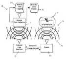
- a passive wireless sensor systemincluding a reader 10 in remote communication with a sensor 12 is provided.
- the readeris capable of exciting the sensor 12 by transmitting a signal, such as a radio frequency (“RF”) pulse, at or near the resonant frequency of the sensor 12 .
- RFradio frequency
- the sensor 12may emit a ring frequency for a short period of time in response to the excitation pulse from the reader 10 .
- the sensor 12may be a passive device, capable of emitting a ring signal in response to an excitation signal at or near the resonant frequency of the sensor 12 .
- the sensor 12may be configured to sense a specific parameter.
- the sensor 12may include a fixed inductor and a capacitor that varies based on the sensed parameter. The varying capacitance alters the resonant and ring frequencies of the sensor 12 . It should be appreciated, however, that the sensor 12 may be any wireless sensor known in the art capable of remote communication with the reader 10 .
- the senor 12is described as an RF resonant sensor, it will be appreciated that the sensor 12 may be a acoustically resonant sensor, optically resonant sensor, or other similar sensor known in the art.
- the corresponding reader 10may employ corresponding signals to activate the sensor 12 .
- the sensor 12may be an active sensor or a passive sensor.
- the reader 10may excite the sensor 12 by transmitting an excitation pulse 14 in the vicinity of the sensor 12 .
- the readermay emit a radio frequency (“RF”) excitation pulse 14 at or near the resonant frequency of the sensor 12 .
- the sensor 12may emit a ring signal 16 in response to the excitation pulse 14 .
- the reader 10may determine the frequency of the ring signal 16 in order to determine the sensed parameter value.
- RFradio frequency
- the reader 10may also communicate with a data interface 17 .
- the reader 10 and data interface 17may be connected directly or indirectly, or may communicate via a remote connection.
- the reader 10may send information, such as data related to the sensor 12 , to the data interface 17 .
- the reader 10may further send information regarding the status of the reader 10 to the data interface 17 .
- the data interface 17may provide configuration information to the reader 10 .
- the data interface 17may provide information regarding schedules and intervals for sampling the sensor 12 .
- the data interface 17may communicate with a remote data system 18 to exchange status and control signals, as well as provide sensor data.
- the remote data system 18may include a data gathering module 19 to receive data from the data interface 17 , a data logging module 20 to store the received data, and a data display 21 to display the sensor data.
- the reader 10includes circuitry to send the excitation pulse 14 , receive the ring signal 16 , and process the ring signal 16 .
- the reader 10includes a timing and control circuitry 22 to configure and activate the other circuits in the reader 10 .
- the solid arrows between the timing and control circuitry 22represent the control interfaces, such as digital or low-frequency signals.
- the timing and control circuitry 22further generates an RF signal (illustrated as the broken line arrow) that is sent to a transmit circuitry 24 .
- the transmit circuitry 24receives the RF signal and sends out the excitation pulse 14 to excite the sensor 12 .
- the timing and control circuitry 22may only provide the RF signal to the transmit circuitry 24 during the intervals when the excitation pulse is being transmitted to prevent leakage or coupling.
- the reader 10further includes an antenna 26 connected to the transmit circuitry 24 and a receive circuitry 28 .
- the transmit circuitry 24utilizes the antenna 26 for transmitting the excitation pulse 14
- the receive circuitry 28utilizes the antenna 26 for receiving the ring signal 16 .
- the antenna 26is connected to both the transmit circuitry 24 and the receive circuitry 28 at all times instead of being switched between transmit and receive.
- This shared antenna 26 designrequires special consideration to prevent damage to the receive circuitry 28 . Specifically, care must be taken not to overload the very sensitive amplifier stages of the receive circuitry 28 .
- the reader 10requires a fast transition between the extreme overdrive condition present while the transmit circuitry 24 is driving the antenna 26 and the low voltage condition present at the antenna 26 during the receive and amplify phases.
- the voltage at the antenna 26may exceed 200 volts peak-to-peak during transmission of the excitation pulse, and may be single-digit millivolts, decaying rapidly to micro-volts, during reception immediately following the excitation pulse 14 .
- the reader 10is described as having a shared antenna 26 , it will be appreciated that the reader 10 may incorporate more than one antenna to separately perform the functions of transmitting the excitation pulse 14 and receiving the ring signal 16 .
- the reader 10further includes a PLL 30 to receive and lock onto the ring signal 16 .
- the receive circuitry 28may amplify and condition the ring signal 16 before sending it to the PLL 30 .
- the PLL 30includes a voltage controlled oscillator (“VCO”) 32 that operates at a frequency higher than the ring signal 16 frequency.
- VCO 32interfaces with a frequency counter 34 which counts the VCO 32 frequency, and provides the count to a external interface circuitry 36 for transfer to the data interface 17 .
- Each component of the reader 10is designed to operate efficiently and reduce power consumption. To that end, the reader 10 includes a reduced power mode to conserve power.
- the timing and control circuitry 22controls the power status of each component by way of a wakeup timer 38 connected to each component. ( FIG. 3 .) In reduced power mode, some components may be completely powered down while other components may operate in a sleep mode where power remains to maintain configuration but the circuit becomes static to minimize power consumption.
- the timing and control circuitry 22may place each component of the reader 10 in a sleep or powered-down mode after a specified period of inactivity, such as a few milliseconds when the reader 10 is not sampling the sensor 12 .
- a specified period of inactivitysuch as a few milliseconds when the reader 10 is not sampling the sensor 12 .
- the specified period of time before entering into reduced power modemay be adjustable.
- the timing and control circuitry 22may include a configuration buffer 40 that receives timing instructions from the external interface circuitry 36 . The instructions establish the timing period before entering into reduced power mode, and other timing periods for the wakeup timer 38 .
- the wakeup timer 38may wake up each component of the reader 10 at the appropriate time to ensure that each component is in an operational state when needed. Specifically, the wakeup timer 38 may communicate with a transmit timer 42 , a receive timer 46 , a PLL timer 48 , and a frequency counter timer 50 to wake up and control the respective components of the reader 10 . Once initiated, each of these timers may control and power up the respective component. When configured, the wakeup timer 38 may delay for a specified interval, which may be zero seconds, before sending an initiate signal 52 to start the other timers. As illustrated in FIG. 3 , the initiate signal 52 is not shown as a continuous line from the wakeup timer 38 to the respective timers in order to prevent line crossings and minimize confusion.
- the transmit timer 42establishes proper sequence and period to the power control 54 , damp control 56 , Q control 58 , and RF enable 60 signals to properly sequence the transmit circuitry 24 and transmit frequency generator 44 .
- the power control signal 54controls the power status and sleep status of the transmit circuitry 24 .
- the damp control signal 56controls the activation of a damping circuit in the transmit circuitry 24 to quickly dissipate antenna 26 energy at the end of a transmission period.
- the Q control signal 58controls a switching circuit in the transmit circuitry 24 to reduce the Q of the antenna 26 during reception of the ring signal 16 .
- the RF enable signalallows the transmit frequency generator 44 to send an RF signal to the transmit circuitry 24 . In an embodiment, the transmit frequency generator 44 only provides the RF signal to the transmit circuitry 24 during periods where the transmit circuitry 24 is transmitting an excitation pulse 14 .
- the receive timer 46is configured to establish proper sequence and period to the power control signal 62 to properly sequence the receive circuitry 28 .
- the PLL timer 48establishes proper sequence and period to the power control 64 and S/H mode 66 signals to properly sequence the PLL 30 .
- the power control signal 64controls the power status and sleep status of the PLL 30 .
- the S/H mode signal 66controls a sample and hold circuit in the PLL 30 , used to cause the PLL to lock onto the transmitted frequency then onto the ring signal 16 frequency, then hold the VCO 32 frequency at the locked frequency until counting is complete.
- the frequency counter timer 50establishes proper sequence and count interval to the power control 68 and start/stop count 70 signals to properly sequence the frequency counter 34 .
- the power control signal 68controls the power status and sleep status of the frequency counter 34 .
- the start/stop count signal 70controls the time that the frequency counter 34 begins and ends counting the VCO 32 frequency.
- the excitation pulse 14does not require significant transmission time because a single short transmission of energy results in a single and complete sample of the ring signal 16 .
- Power consumptionmay be reduced by using a lower transmission duty cycle, thereby reducing the duty cycle of transmit, receive, counting, and digital processing circuitry. By reducing power consumption battery power becomes a much more viable option to power the system.
- the excitation pulse 14may be configured to maximize several system parameters. For example, if a fixed frequency excitation pulse 14 is used, the frequency of the burst may be configured to maximize parameters such as maximum allowable transmit peak power, maximum freedom from in-band or near-band interference during the “receive” interval while the PLL is being locked to the ring signal 16 , maximum worldwide acceptance of a particular frequency for reader transmissions for the desired sensor purpose, or other such criteria.
- a level shifter 72 of the transmit circuitry 24receives control signals 54 , 56 , 58 and the RF signal 60 from the timing and control circuitry 22 .
- the level shifter 72buffers the inputs and convert control logic levels to circuit drive levels.
- a transmit driver 74amplifies the RF signal 60 to provide sufficient power to drive the antenna 26 .
- the Q control circuit 76is activated during receive to reduce the Q of the combined antenna 26 and tuning and D.C. block 82 .
- a damping circuit 78is briefly activated immediately at the end of transmission of the excitation pulse 14 to absorb energy in the antenna and allow the antenna to respond to the ring signal 16 .
- the damping circuit 78may provide a different Q factor to the antenna to improve reception of the ring signal 16 .
- the power control circuitry 80controls the power-on and sleep mode for components in the transmit circuitry 24 .
- the tuning and D.C. block 82adjusts tuning for the antenna 26 and prevents direct current from improperly biasing the damping circuit 78 .
- the RF output or excitation pulse 14 from the transmit circuitryis routed to both the antenna 26 and the receive circuitry 28 .
- a high Z buffer/clamp 84includes a high impedance (“high Z”) input device that limits the effect of the receive circuitry 28 on the tuning performed by the tuning and D.C. block 82 .
- the high Z buffer/clamp 84further serves to protect the amplifier stages 86 from the extreme voltages present on the antenna 26 during transmission of the excitation pulse 14 . Voltages at the antenna 26 may reach upwards of 200 volts peak-to-peak during transmission of the excitation pulse, requiring only approximately 60 pico-farads of capacitance to tune the antenna 26 .
- a 1 pico-farad capacitoris used as a high impedance input current limiting device on a 13.5 mega-hertz transmit circuit.
- Low capacitance diode junctions that shunt over-voltage to the power supply and under-voltage to groundmay be used as clamping devices.
- the amplifier stages 86amplify the ring signal 16 to a sufficient level to drive the PLL 30 input. Careful design of the amplifier stages 86 is required to achieve adequate transient response when the transmitted excitation pulse 14 signal is removed and damped, and the low level ring signal 16 is received.
- Common gate amplifier stages with low Q tuned reactive drain loadsmay be used to condition the high Z buffer/clamp 84 output, followed by several filters interspersed between high gain amplifier stages.
- the filtersmay be either resistor-capacitor (“RC”) filters or inductor-capacitor (“LC”) filters. In an embodiment, the filters may all be RC bandpass filters.
- Another common gate amplifier stage with low Q tuned reactive drain loadmay be used for final bandpass conditioning prior to feeding the signal to the PLL 30 input.
- This designenables all of these amplifier types to perform from extremely low signal input levels to extremely high signal input levels without signal distortion such as frequency doubling or halving due to stage saturation characteristics, as well as the excellent high input impedance achievable with the common-gate amplifier stages and the outstanding transient response characteristics of the RC filter interspersed between high gain amplifier stages. Special care must be taken in stage-to-stage power and signal isolation to prevent unwanted oscillations due to the extreme gain associated with the amplifier stages 86 .
- Power control circuitry 88may apply and remove power to and from the amplifier stages 86 and the buffer in the high Z buffer/clamp 84 to reduce power consumption. It should be noted that the high Z buffer/clamp 84 is designed to provide full protection even with power removed as excess energy will merely power up the amplifier stages 86 until dissipated. The input impedance is high enough to limit excess energy to prevent overpowering the amplifier stages 86 . In an embodiment, the receive circuitry 28 is active during the transmission of the excitation pulse 14 to decrease the time required for the PLL 30 to lock onto the ring signal 16 .
- the PLL 30receives the amplified and conditioned ring signal 16 from the receive circuitry 28 .
- the RF signal from the receive circuitry 28 amplifier stages 86feeds an RF buffer 90 of the PLL 30 .
- the RF buffer 90may feed the RF signal to an optional RF divider 92 that divides the RF signal frequency by an integer value. ( FIG. 6 .)
- the RF divider 92then feeds the RF signal to a first input of a phase frequency detector 94 .
- the output of the frequency detector 94feeds a sample-and-hold (S/H) error amplifier 96 .
- the S/H error amplifier 96controls the frequency of the VCO 32 .
- the output of the VCO 32feeds the VCO divider 98 , which output in turn feeds a second input to the phase frequency detector 94 .
- the PLL 30may include an output buffer 102 to reduce loading of the VCO 32 while forwarding the VCO signal frequency to the frequency counter 34 .
- the VCO divider 98allows the VCO 32 to operate at a frequency significantly higher than the ring frequency 16 . As a result, the time required to count and record the VCO signal frequency may be significantly reduced. Moreover, the shorter count interval reduces VCO drift during counting and allows a higher sample rate.
- the phase frequency detector 94is configured to determine the frequency and phase error between the divided RF signal and the divided VCO signal. This is best accomplished by filtering and amplifying the RF signal that is fed to the S/H error amplifier 96 . Further, the S/H feature may optimally forward the filtered and amplified signal to control the VCO 32 . In this manner, a closed control loop is formed that causes the VCO 32 frequency to equal to the ring signal 16 frequency times the VCO divider 98 integer divided by the RF divider 92 integer.
- the PLL 30may include additional frequency dividers to optimize the circuit design and increase the potential VCO 32 frequency range.
- the PLL timer 48sends a S/H mode control signal 66 to the S/H error amplifier 96 of the PLL 30 .
- the S/H mode control signal 66may place the VCO 32 in a sample mode.
- the VCO 32is placed in sample mode for a predetermined length of time. In sample mode, the VCO signal frequency is adjusted to match the ring signal frequency, as described above.
- the S/H mode control signal 66is placed in the hold mode, the S/H error amplifier 96 will hold its output constant, causing the control voltage to the VCO 32 to be approximately constant over a length of time sufficient to count the VCO signal frequency.
- the power control signal from the PLL timer 48 to the power control circuitry 104determines whether the PLL 30 is in a power on or a sleep/power-off mode to conserve electrical power.
- a control and communication link(not shown) may be required to set the RF divider 92 integer, the VCO divider 98 integer, and the phase frequency detector 94 outputs and output configurations.
- the communications linkmay be specific to the particular PLL 30 used.
- the frequency counter 34includes counter stages 106 , a counter buffer 108 , and a power control circuitry 110 .
- the frequency counter timer 50sends a start/stop control input to the counter stages 106 and counter buffer 108 .
- the frequency counter timer 50also sends a power control input to the power control circuitry 110 .
- the counter stages 106count the VCO signal frequency from the PLL 30 output buffer 102 .
- the counter stages 106start counting when the start/stop control commands start, and end when the start/stop control commands stop. When the start/stop control commands stop, the counter buffer 108 is loaded with the count value from the counter stages 106 .
- the power control circuitry 110controls the power-on and sleep modes for components in the frequency counter 34 .
- the counter buffer 108 outputmay supply a count input to the external interface circuitry 36 .
- the ring frequency 16and subsequently the sensed parameter, may be determined from the frequency count.
- the reader 10sequences as follows. During periods of time when the sensor 12 is not being sampled, all components of the reader 10 are placed in reduced power mode.
- the wakeup timer 38 in the timing and control circuitry 22is configured for a particular sample delay or sample interval. At the specified time, the wakeup timer 38 initiates a sample sequence. Specifically, the wakeup timer 38 powers up or wakes up each component of the reader at appropriate times to ensure each component is in an operational state when needed.
- the external interface circuitry 36consumes minimal power when not actively communicating so is maintained in a ready condition at all times.
- the timing and control circuitry 22provides the RF signal to the transmit circuitry 24 for a short period of time, such as approximately 20 microseconds.
- the RF signal from the timing and control circuitry 22is then secured and the transmit circuitry 24 is controlled to damp the antenna 26 quickly.
- the transmit circuitry 24is then placed in an appropriate mode to allow reception of the ring signal 16 at the antenna 26 .
- the antenna 26 dampingis greater than the ring signal 16 damping.
- the receive circuitry 28receives, conditions, and clamps the transmitted RF signal at the antenna 26 .
- the receive circuitrytransitions into a high-gain reception mode to receive the ring signal 16 from the antenna 26 .
- the PLL 30is in sample mode to allow the RF buffer 90 to receive the conditioned output of the receive circuitry 28 .
- the PLL 30shifts from locking onto the transmitted excitation pulse 14 frequency to locking onto the ring signal 16 frequency.
- the PLL 30After a time interval sufficient for the PLL 30 to lock onto the ring signal 16 frequency, the PLL 30 is shifted to hold mode to maintain VCO 32 frequency at ring signal 16 frequency.
- the receive circuitry 28 and transmit circuitry 24are powered down or placed in sleep mode as appropriate.
- the timing and control circuitry 22instructs the frequency counter 34 to conduct a controlled interval count of the VCO 32 frequency.
- the PLL 30 componentsare powered down or placed in sleep mode as appropriate and the count value is transferred to the external interface circuitry 36 .
- the frequency counter 34 componentsare then powered down or placed in sleep mode as appropriate, and subsequently the timing and control circuitry 22 components are powered down or placed in sleep mode as appropriate. If programmed for interval sampling, the timing and control circuitry 22 wakeup timer 38 counts until the next sample is due. Otherwise, the timing and control circuitry 22 awaits a wakeup command with any other needed instructions from the external interface circuitry 36 .
Landscapes
- Health & Medical Sciences (AREA)
- Life Sciences & Earth Sciences (AREA)
- Engineering & Computer Science (AREA)
- Physics & Mathematics (AREA)
- Molecular Biology (AREA)
- General Health & Medical Sciences (AREA)
- Pathology (AREA)
- Biomedical Technology (AREA)
- Heart & Thoracic Surgery (AREA)
- Medical Informatics (AREA)
- Veterinary Medicine (AREA)
- Surgery (AREA)
- Animal Behavior & Ethology (AREA)
- Biophysics (AREA)
- Public Health (AREA)
- Computer Networks & Wireless Communication (AREA)
- Cardiology (AREA)
- General Physics & Mathematics (AREA)
- Vascular Medicine (AREA)
- Physiology (AREA)
- Arrangements For Transmission Of Measured Signals (AREA)
- Measuring And Recording Apparatus For Diagnosis (AREA)
- Near-Field Transmission Systems (AREA)
Abstract
Description
This non-provisional application is a continuation of U.S. patent application Ser. No. 13/423,693 filed on Mar. 19, 2012, which is a continuation of U.S. patent application Ser. No. 12/419,326 filed on Apr. 7, 2009, which is a continuation-in-part of U.S. patent application Ser. No. 12/075,858 filed on Mar. 14, 2008, which claims priority to U.S. Provisional Application No. 60/918,164 filed on Mar. 15, 2007.
This invention relates generally to reading passive wireless sensors, and more particularly to a reader circuitry for exciting and sensing data from passive wireless sensors.
Passive wireless sensor systems that employ resonant circuit technology are known. These systems utilize a passive wireless sensor in remote communication with excitation and reader circuitry. Often the wireless sensor is implanted at a specific location, such as within the human body, to detect and report a sensed parameter. The sensed parameter varies the resonant circuit frequency of the wireless sensor. The reader device samples the resonant frequency of the wireless sensor to determine the sensed parameter.
U.S. Pat. No. 4,127,110 by Bullara discloses a sensor for measuring brain fluid pressure measurement. U.S. Pat. No. 4,206,762 by Cosman discloses a similar sensor for measuring internal pressure. Specifically, the Cosman patent describes the use of a grid dip system for wirelessly measuring the resonant frequency of the sensor. In addition, the Cosman patent discloses the possibility of a battery powered portable reader device.
Several methods of reading passive wireless sensors have also been described in prior patents. For example, the Cosman patent discloses an external oscillator circuit that uses the implanted sensor for tuning, and a grid dip measurement system for measurement of sensor resonant frequency. U.S. Pat. No. 6,015,386 by Kensey, et al., discloses a reader that excites the passive sensor by transmitting frequency sweeps and uses a phase detector on the transmit signal to detect the time during the sweep where the transmitted frequency matches the resonance frequency of the sensor. U.S. Pat. No. 6,206,835 by Spillman, et al., discloses a medical implant application for reader technology disclosed in U.S. Pat. No. 5,581,248 by Spillman, et al. This reader technology detects a frequency dependent variable impedance loading effect on the reader by the sensor's detected parameter. U.S. Pat. No. 7,432,723 by Ellis, et al., discloses a reader with energizing loops each tuned to and transmitting different frequencies spaced to ensure that the bandwidth of the sensor allows resonant excitation of the sensor. Ellis uses a ring-down response from the appropriate energizing loop to determine the sensor resonant frequency.
Some readers utilize phased-locked-loop (“PLL”) circuitry to lock onto the sensor's resonant frequency. U.S. Pat. No. 7,245,117 by Joy, et al. discloses an active PLL circuit and signal processing circuit that adjusts a transmitting PLL frequency until the received signal phase and the transmitting PLL signal phase match. When this match occurs, the transmitting PLL frequency is equal to the sensor resonant frequency.
PLL circuits may incorporate sample and hold (S/H) functions to sample the input frequency and hold the PLL at a given frequency. PLLs with S/H may be used in a variety of applications. For example, U.S. Pat. No. 4,531,526 by Genest discloses a reader that uses a PLL circuit with a S/H circuit to adjust the transmitted frequency of the reader to match the resonant frequency received from the sensor. This is done to maximize sensor response to the next transmission and measures the decay rate of the sensor resonance amplitude to extract the sensor value. U.S. Pat. No. 4,644,420 by Buchan describes a PLL with a S/H used to sample a tape data stream and maintain an appropriate sampling frequency for evaluation of digital data pulses on the tape. U.S. Pat. No. 5,006,819 by Buchan, et al., provides additional enhancements to this concept. U.S. Pat. No. 5,920,233 by Denny describes a high-speed sampling technique using a S/H circuit with a PLL to reduce the charge pump noise from the phase-frequency detector to enhance the low jitter performance of a frequency synthesizing circuit. U.S. Pat. No. 4,511,858 by Charvit, et al., discloses a PLL with a S/H circuit to pre-position the control voltage of a voltage controlled oscillator when the PLL lock frequency is being changed. This is done to enhance the response speed of the PLL when changing the desired synthesized frequency. U.S. Pat. No. 6,570,457 by Fischer and U.S. Pat. No. 6,680,654 by Fischer, et al., disclose a PLL with S/H circuitry to enhance PLL frequency stepping as well as offset correction feature. U.S. Pat. No. 3,872,455 by Fuller, et al. discloses a PLL having a digital S/H to freeze the frequency display and preload the frequency counter when a PLL phase lock is detected.
Current designs for passive sensor readers, such as those disclosed above, suffer from a number of deficiencies. Swept frequency sensor readers similar to those described in the Cosman, Kensey, Ellis and Spillman patents require relatively wide bandwidth allowance by the government body regulating radio transmissions. This limits other uses of the spectrum and makes interference a potential issue. Readers that track the resonant frequency of a passive resonant sensor with a variable frequency transmitter, such as Genest, Ellis, and Joy also suffer from similar problems. Moreover, the amount of electrical power needed for transmissions, signal processing, sampling, and tracking the resonant frequency of a sensor using digitally controlled frequency tracking or swept frequency systems is significant and limits the ability to use battery power in a reader, as well as limiting the longevity of batteries in a battery powered reader. Accordingly, an improved passive sensor reader is needed in the art.
Reference to the detailed description is taken in connection with the following illustrations:
A reader device is provided to interface with a wireless sensor. The reader emits a short pulse of energy or a short burst of radio frequency energy to cause the wireless sensor to ring. Immediately after the transmission, the reader receives and amplifies the sensor signal, then sends the signal to a phase-locked loop (“PLL”) that locks to the sensor ring frequency. Once the PLL has locked to the ring frequency, the PLL's voltage controlled oscillator (“VCO”) is placed in a hold mode to maintain the VCO frequency at the locked frequency. The VCO frequency is counted to determine the sensor resonant frequency.
A passive wireless sensor system including areader 10 in remote communication with asensor 12 is provided. The reader is capable of exciting thesensor 12 by transmitting a signal, such as a radio frequency (“RF”) pulse, at or near the resonant frequency of thesensor 12. (SeeFIG. 1 .) Thesensor 12 may emit a ring frequency for a short period of time in response to the excitation pulse from thereader 10.
Thesensor 12 may be a passive device, capable of emitting a ring signal in response to an excitation signal at or near the resonant frequency of thesensor 12. Thesensor 12 may be configured to sense a specific parameter. For example, thesensor 12 may include a fixed inductor and a capacitor that varies based on the sensed parameter. The varying capacitance alters the resonant and ring frequencies of thesensor 12. It should be appreciated, however, that thesensor 12 may be any wireless sensor known in the art capable of remote communication with thereader 10. Further, while thesensor 12 is described as an RF resonant sensor, it will be appreciated that thesensor 12 may be a acoustically resonant sensor, optically resonant sensor, or other similar sensor known in the art. The correspondingreader 10 may employ corresponding signals to activate thesensor 12. Further, thesensor 12 may be an active sensor or a passive sensor.
Thereader 10 may excite thesensor 12 by transmitting anexcitation pulse 14 in the vicinity of thesensor 12. For example, the reader may emit a radio frequency (“RF”)excitation pulse 14 at or near the resonant frequency of thesensor 12. Thesensor 12 may emit aring signal 16 in response to theexcitation pulse 14. Thereader 10 may determine the frequency of thering signal 16 in order to determine the sensed parameter value.
Thereader 10 may also communicate with adata interface 17. Thereader 10 and data interface17 may be connected directly or indirectly, or may communicate via a remote connection. Thereader 10 may send information, such as data related to thesensor 12, to thedata interface 17. Thereader 10 may further send information regarding the status of thereader 10 to thedata interface 17. The data interface17 may provide configuration information to thereader 10. For example, thedata interface 17 may provide information regarding schedules and intervals for sampling thesensor 12.
The data interface17 may communicate with aremote data system 18 to exchange status and control signals, as well as provide sensor data. Theremote data system 18 may include adata gathering module 19 to receive data from thedata interface 17, adata logging module 20 to store the received data, and adata display 21 to display the sensor data.
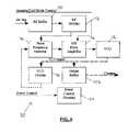
Thereader 10 includes circuitry to send theexcitation pulse 14, receive thering signal 16, and process thering signal 16. (FIG. 2 .) For example, thereader 10 includes a timing andcontrol circuitry 22 to configure and activate the other circuits in thereader 10. The solid arrows between the timing andcontrol circuitry 22 represent the control interfaces, such as digital or low-frequency signals. The timing andcontrol circuitry 22 further generates an RF signal (illustrated as the broken line arrow) that is sent to a transmitcircuitry 24. The transmitcircuitry 24 receives the RF signal and sends out theexcitation pulse 14 to excite thesensor 12. The timing andcontrol circuitry 22 may only provide the RF signal to the transmitcircuitry 24 during the intervals when the excitation pulse is being transmitted to prevent leakage or coupling.
Thereader 10 further includes anantenna 26 connected to the transmitcircuitry 24 and a receivecircuitry 28. The transmitcircuitry 24 utilizes theantenna 26 for transmitting theexcitation pulse 14, while the receivecircuitry 28 utilizes theantenna 26 for receiving thering signal 16. In an embodiment, theantenna 26 is connected to both the transmitcircuitry 24 and the receivecircuitry 28 at all times instead of being switched between transmit and receive. This sharedantenna 26 design requires special consideration to prevent damage to the receivecircuitry 28. Specifically, care must be taken not to overload the very sensitive amplifier stages of the receivecircuitry 28. Additionally, thereader 10 requires a fast transition between the extreme overdrive condition present while the transmitcircuitry 24 is driving theantenna 26 and the low voltage condition present at theantenna 26 during the receive and amplify phases. For instance, the voltage at theantenna 26 may exceed200 volts peak-to-peak during transmission of the excitation pulse, and may be single-digit millivolts, decaying rapidly to micro-volts, during reception immediately following theexcitation pulse 14. While thereader 10 is described as having a sharedantenna 26, it will be appreciated that thereader 10 may incorporate more than one antenna to separately perform the functions of transmitting theexcitation pulse 14 and receiving thering signal 16.
Thereader 10 further includes aPLL 30 to receive and lock onto thering signal 16. The receivecircuitry 28 may amplify and condition thering signal 16 before sending it to thePLL 30. ThePLL 30 includes a voltage controlled oscillator (“VCO”)32 that operates at a frequency higher than thering signal 16 frequency. TheVCO 32 interfaces with afrequency counter 34 which counts theVCO 32 frequency, and provides the count to aexternal interface circuitry 36 for transfer to thedata interface 17. By operating theVCO 32 at a higher frequency than thering signal 16, the time required to count and record theVCO 32 frequency may be significantly decreased.
Each component of thereader 10 is designed to operate efficiently and reduce power consumption. To that end, thereader 10 includes a reduced power mode to conserve power. The timing andcontrol circuitry 22 controls the power status of each component by way of awakeup timer 38 connected to each component. (FIG. 3 .) In reduced power mode, some components may be completely powered down while other components may operate in a sleep mode where power remains to maintain configuration but the circuit becomes static to minimize power consumption.
The timing andcontrol circuitry 22 may place each component of thereader 10 in a sleep or powered-down mode after a specified period of inactivity, such as a few milliseconds when thereader 10 is not sampling thesensor 12. However, it will be appreciated that the specified period of time before entering into reduced power mode may be adjustable. For example, the timing andcontrol circuitry 22 may include aconfiguration buffer 40 that receives timing instructions from theexternal interface circuitry 36. The instructions establish the timing period before entering into reduced power mode, and other timing periods for thewakeup timer 38.
Thewakeup timer 38 may wake up each component of thereader 10 at the appropriate time to ensure that each component is in an operational state when needed. Specifically, thewakeup timer 38 may communicate with a transmittimer 42, a receivetimer 46, aPLL timer 48, and afrequency counter timer 50 to wake up and control the respective components of thereader 10. Once initiated, each of these timers may control and power up the respective component. When configured, thewakeup timer 38 may delay for a specified interval, which may be zero seconds, before sending an initiatesignal 52 to start the other timers. As illustrated inFIG. 3 , the initiatesignal 52 is not shown as a continuous line from thewakeup timer 38 to the respective timers in order to prevent line crossings and minimize confusion.
Once initiated, the transmittimer 42 establishes proper sequence and period to thepower control 54,damp control 56,Q control 58, and RF enable60 signals to properly sequence the transmitcircuitry 24 and transmitfrequency generator 44. Thepower control signal 54 controls the power status and sleep status of the transmitcircuitry 24. Thedamp control signal 56 controls the activation of a damping circuit in the transmitcircuitry 24 to quickly dissipateantenna 26 energy at the end of a transmission period. TheQ control signal 58 controls a switching circuit in the transmitcircuitry 24 to reduce the Q of theantenna 26 during reception of thering signal 16. The RF enable signal allows the transmitfrequency generator 44 to send an RF signal to the transmitcircuitry 24. In an embodiment, the transmitfrequency generator 44 only provides the RF signal to the transmitcircuitry 24 during periods where the transmitcircuitry 24 is transmitting anexcitation pulse 14.
The receivetimer 46 is configured to establish proper sequence and period to thepower control signal 62 to properly sequence the receivecircuitry 28.
ThePLL timer 48 establishes proper sequence and period to thepower control 64 and S/H mode 66 signals to properly sequence thePLL 30. Thepower control signal 64 controls the power status and sleep status of thePLL 30. The S/H mode signal 66 controls a sample and hold circuit in thePLL 30, used to cause the PLL to lock onto the transmitted frequency then onto thering signal 16 frequency, then hold theVCO 32 frequency at the locked frequency until counting is complete.
Thefrequency counter timer 50 establishes proper sequence and count interval to thepower control 68 and start/stop count 70 signals to properly sequence thefrequency counter 34. Thepower control signal 68 controls the power status and sleep status of thefrequency counter 34. The start/stop count signal 70 controls the time that thefrequency counter 34 begins and ends counting theVCO 32 frequency.
The transmitcircuitry 24 is configured to transmit theexcitation pulse 14 to thesensor 12 by way of theantenna 26. (FIG. 4 .) Theexcitation pulse 14 may be a fixed or rapidly varying frequency burst at or near the resonant frequency of thesensor 12. For example, theexcitation pulse 14 may be a fixed frequency burst within several bandwidths of thesensor 12 resonant frequency. Alternatively, theexcitation pulse 14 may be a fixed or rapidly varying frequency burst or sweep of a very short duration at or near a frequency harmonically related to thesensor 12 resonant frequency. Theexcitation pulse 14 may also be an ultra-wide band pulse. This plurality ofexcitation pulse 14 approaches is effective because thering signal 16 is received when theexcitation pulse 14 transmissions have ceased. Therefore,excitation pulse 14 transmissions may be limited to frequency bands, amplitudes, and modulation schemes acceptable to regulatory government bodies. Radio frequency regulations generally may not apply to thesensor 12 as thesensor 12 is a purely passive device.
Theexcitation pulse 14 does not require significant transmission time because a single short transmission of energy results in a single and complete sample of thering signal 16. Power consumption may be reduced by using a lower transmission duty cycle, thereby reducing the duty cycle of transmit, receive, counting, and digital processing circuitry. By reducing power consumption battery power becomes a much more viable option to power the system.
Theexcitation pulse 14 may be configured to maximize several system parameters. For example, if a fixedfrequency excitation pulse 14 is used, the frequency of the burst may be configured to maximize parameters such as maximum allowable transmit peak power, maximum freedom from in-band or near-band interference during the “receive” interval while the PLL is being locked to thering signal 16, maximum worldwide acceptance of a particular frequency for reader transmissions for the desired sensor purpose, or other such criteria.
A level shifter72 of the transmitcircuitry 24 receives control signals54,56,58 and theRF signal 60 from the timing andcontrol circuitry 22. The level shifter72 buffers the inputs and convert control logic levels to circuit drive levels. A transmit driver74 amplifies theRF signal 60 to provide sufficient power to drive theantenna 26. The Q control circuit76 is activated during receive to reduce the Q of the combinedantenna 26 and tuning and D.C. block82. A damping circuit78 is briefly activated immediately at the end of transmission of theexcitation pulse 14 to absorb energy in the antenna and allow the antenna to respond to thering signal 16. The damping circuit78 may provide a different Q factor to the antenna to improve reception of thering signal 16. The power control circuitry80 controls the power-on and sleep mode for components in the transmitcircuitry 24. The tuning and D.C. block82 adjusts tuning for theantenna 26 and prevents direct current from improperly biasing the damping circuit78. The RF output orexcitation pulse 14 from the transmit circuitry is routed to both theantenna 26 and the receivecircuitry 28.
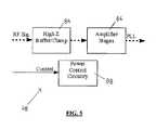
Once theexcitation pulse 14 is transmitted by the transmitcircuitry 24, the receivecircuitry 28 is configured to listen for thering signal 16. With reference toFIG. 5 , a high Z buffer/clamp 84 includes a high impedance (“high Z”) input device that limits the effect of the receivecircuitry 28 on the tuning performed by the tuning and D.C. block82. The high Z buffer/clamp 84 further serves to protect the amplifier stages86 from the extreme voltages present on theantenna 26 during transmission of theexcitation pulse 14. Voltages at theantenna 26 may reach upwards of 200 volts peak-to-peak during transmission of the excitation pulse, requiring only approximately 60 pico-farads of capacitance to tune theantenna 26. In an embodiment, a 1 pico-farad capacitor is used as a high impedance input current limiting device on a 13.5 mega-hertz transmit circuit. Low capacitance diode junctions that shunt over-voltage to the power supply and under-voltage to ground may be used as clamping devices.
The amplifier stages86 amplify thering signal 16 to a sufficient level to drive thePLL 30 input. Careful design of the amplifier stages86 is required to achieve adequate transient response when the transmittedexcitation pulse 14 signal is removed and damped, and the lowlevel ring signal 16 is received. Common gate amplifier stages with low Q tuned reactive drain loads may be used to condition the high Z buffer/clamp 84 output, followed by several filters interspersed between high gain amplifier stages. The filters may be either resistor-capacitor (“RC”) filters or inductor-capacitor (“LC”) filters. In an embodiment, the filters may all be RC bandpass filters. Another common gate amplifier stage with low Q tuned reactive drain load may be used for final bandpass conditioning prior to feeding the signal to thePLL 30 input. This design enables all of these amplifier types to perform from extremely low signal input levels to extremely high signal input levels without signal distortion such as frequency doubling or halving due to stage saturation characteristics, as well as the excellent high input impedance achievable with the common-gate amplifier stages and the outstanding transient response characteristics of the RC filter interspersed between high gain amplifier stages. Special care must be taken in stage-to-stage power and signal isolation to prevent unwanted oscillations due to the extreme gain associated with the amplifier stages86.
ThePLL 30 receives the amplified and conditionedring signal 16 from the receivecircuitry 28. With reference toFIGS. 5 and 6 , the RF signal from the receivecircuitry 28 amplifier stages86 feeds anRF buffer 90 of thePLL 30. TheRF buffer 90 may feed the RF signal to anoptional RF divider 92 that divides the RF signal frequency by an integer value. (FIG. 6 .) TheRF divider 92 then feeds the RF signal to a first input of aphase frequency detector 94. The output of thefrequency detector 94 feeds a sample-and-hold (S/H)error amplifier 96. The S/H error amplifier 96 controls the frequency of theVCO 32. The output of theVCO 32 feeds theVCO divider 98, which output in turn feeds a second input to thephase frequency detector 94. ThePLL 30 may include anoutput buffer 102 to reduce loading of theVCO 32 while forwarding the VCO signal frequency to thefrequency counter 34. TheVCO divider 98 allows theVCO 32 to operate at a frequency significantly higher than thering frequency 16. As a result, the time required to count and record the VCO signal frequency may be significantly reduced. Moreover, the shorter count interval reduces VCO drift during counting and allows a higher sample rate.
Thephase frequency detector 94 is configured to determine the frequency and phase error between the divided RF signal and the divided VCO signal. This is best accomplished by filtering and amplifying the RF signal that is fed to the S/H error amplifier 96. Further, the S/H feature may optimally forward the filtered and amplified signal to control theVCO 32. In this manner, a closed control loop is formed that causes theVCO 32 frequency to equal to thering signal 16 frequency times theVCO divider 98 integer divided by theRF divider 92 integer. ThePLL 30 may include additional frequency dividers to optimize the circuit design and increase thepotential VCO 32 frequency range.
ThePLL timer 48 sends a S/Hmode control signal 66 to the S/H error amplifier 96 of thePLL 30. The S/Hmode control signal 66 may place theVCO 32 in a sample mode. In an embodiment, theVCO 32 is placed in sample mode for a predetermined length of time. In sample mode, the VCO signal frequency is adjusted to match the ring signal frequency, as described above. When the S/Hmode control signal 66 is placed in the hold mode, the S/H error amplifier 96 will hold its output constant, causing the control voltage to theVCO 32 to be approximately constant over a length of time sufficient to count the VCO signal frequency.
The power control signal from thePLL timer 48 to thepower control circuitry 104 determines whether thePLL 30 is in a power on or a sleep/power-off mode to conserve electrical power. Depending on the specific PLL that is used, a control and communication link (not shown) may be required to set theRF divider 92 integer, theVCO divider 98 integer, and thephase frequency detector 94 outputs and output configurations. The communications link may be specific to theparticular PLL 30 used.
Thefrequency counter 34 includes counter stages106, acounter buffer 108, and apower control circuitry 110. Thefrequency counter timer 50 sends a start/stop control input to the counter stages106 andcounter buffer 108. Thefrequency counter timer 50 also sends a power control input to thepower control circuitry 110. The counter stages106 count the VCO signal frequency from thePLL 30output buffer 102. The counter stages106 start counting when the start/stop control commands start, and end when the start/stop control commands stop. When the start/stop control commands stop, thecounter buffer 108 is loaded with the count value from the counter stages106. Thepower control circuitry 110 controls the power-on and sleep modes for components in thefrequency counter 34. Thecounter buffer 108 output may supply a count input to theexternal interface circuitry 36. Thering frequency 16, and subsequently the sensed parameter, may be determined from the frequency count.
In operation, thereader 10 sequences as follows. During periods of time when thesensor 12 is not being sampled, all components of thereader 10 are placed in reduced power mode. Thewakeup timer 38 in the timing andcontrol circuitry 22 is configured for a particular sample delay or sample interval. At the specified time, thewakeup timer 38 initiates a sample sequence. Specifically, thewakeup timer 38 powers up or wakes up each component of the reader at appropriate times to ensure each component is in an operational state when needed.
Theexternal interface circuitry 36 consumes minimal power when not actively communicating so is maintained in a ready condition at all times. The timing andcontrol circuitry 22 provides the RF signal to the transmitcircuitry 24 for a short period of time, such as approximately 20 microseconds. The RF signal from the timing andcontrol circuitry 22 is then secured and the transmitcircuitry 24 is controlled to damp theantenna 26 quickly. The transmitcircuitry 24 is then placed in an appropriate mode to allow reception of thering signal 16 at theantenna 26. In an embodiment, when theantenna 26 is configured to receive thering signal 16, theantenna 26 damping is greater than thering signal 16 damping.
During transmission of theexcitation pulse 14, the receivecircuitry 28 receives, conditions, and clamps the transmitted RF signal at theantenna 26. Once transmission of theexcitation pulse 14 ceases and theantenna 26 is configured to receive thering signal 16, the receive circuitry transitions into a high-gain reception mode to receive thering signal 16 from theantenna 26. ThePLL 30 is in sample mode to allow theRF buffer 90 to receive the conditioned output of the receivecircuitry 28. When theantenna 26 begins to receive thering signal 16, thePLL 30 shifts from locking onto the transmittedexcitation pulse 14 frequency to locking onto thering signal 16 frequency. After a time interval sufficient for thePLL 30 to lock onto thering signal 16 frequency, thePLL 30 is shifted to hold mode to maintainVCO 32 frequency atring signal 16 frequency. The receivecircuitry 28 and transmitcircuitry 24 are powered down or placed in sleep mode as appropriate.
Once thePLL 30 is in hold mode, the timing andcontrol circuitry 22 instructs thefrequency counter 34 to conduct a controlled interval count of theVCO 32 frequency. Upon completion of the count, thePLL 30 components are powered down or placed in sleep mode as appropriate and the count value is transferred to theexternal interface circuitry 36. Thefrequency counter 34 components are then powered down or placed in sleep mode as appropriate, and subsequently the timing andcontrol circuitry 22 components are powered down or placed in sleep mode as appropriate. If programmed for interval sampling, the timing andcontrol circuitry 22wakeup timer 38 counts until the next sample is due. Otherwise, the timing andcontrol circuitry 22 awaits a wakeup command with any other needed instructions from theexternal interface circuitry 36.
The embodiment of the invention has been described above and, obviously, modifications and alternations will occur to others upon reading and understanding this specification. The claims as follows are intended to include all modifications and alterations insofar as they are within the scope of the claims or the equivalent thereof.
Claims (23)
1. A method of obtaining a measurement from a remote location, the method comprising:
transmitting a plurality of excitation pulses each at a predetermined frequency to a wireless sensor wherein said predetermined frequency is determined during a period of time when said wireless sensor is not being sampled wherein each excitation pulse is transmitted at the predetermined frequency;
receiving a signal from said wireless sensor in response to said plurality of excitation pulses;
sampling and holding said received signal; and
ascertaining the frequency of said received signal;
wherein said wireless sensor is configured to change its resonant frequency in proportion to at least one sensed parameter.
2. The method ofclaim 1 further comprising generating a count signal at a frequency to match the frequency of said signal from said wireless sensor.
3. The method ofclaim 2 , wherein said count signal is generated by a voltage controlled oscillator.
4. The method ofclaim 2 , wherein the frequency of said count signal is an integer multiple of said ring signal frequency.
5. The method ofclaim 1 , wherein said wireless sensor is a passive sensor.
6. The method ofclaim 5 , wherein said wireless sensor comprises at least one inductor and at least one capacitor.
7. The method ofclaim 6 , wherein at least one of said at least one inductor and said at least one capacitor changes its value in response to said at least one sensed parameter.
8. The method ofclaim 1 , wherein each of said excitation pulses is a different frequency.
9. The method ofclaim 1 , wherein each of said excitation pulses is a radio frequency (RF) pulse.
10. The method ofclaim 1 , wherein said signal from a wireless sensor is a ring signal.
11. A method of obtaining a measurement from a remote location, the method comprising:
transmitting a plurality of excitation pulses to a wireless sensor, wherein said plurality of excitation pulses are spaced apart at fixed time intervals, wherein a frequency of each of said excitation pulses is determined during a period of time when the wireless sensor is not being sampled wherein each excitation pulse is transmitted at the frequency determined during a period of time when the wireless sensor is not being sampled;
receiving a signal from said wireless sensor in response to said plurality of excitation pulses;
sampling and holding said received signal; and
ascertaining the frequency of said received signal;
wherein said wireless sensor is configured to change its resonant frequency in proportion to at least one sensed parameter.
12. The method ofclaim 11 , wherein said fixed time intervals are equal to one another.
13. The method ofclaim 11 , wherein each of said excitation pulses is transmitted at a predetermined frequency.
14. The method ofclaim 11 , wherein said wireless sensor is a passive device.
15. The method ofclaim 11 further comprising generating a count signal at a frequency to match the frequency of said signal from said wireless sensor.
16. The method ofclaim 15 , wherein said count signal is generated by a phase locked loop circuit.
17. A system for obtaining a measurement from a remote location, said system comprising:
a wireless sensor configured to change its resonant frequency in proportion to at least one sensed parameter;
a reader configured to transmit a plurality of excitation pulses at only a fixed frequency to said wireless sensor and to receive at least one signal from said wireless sensor in response to said excitation pulses wherein said fixed frequency is determined before said plurality of excitation pulses are transmitted wherein each excitation pulse is transmitted at the fixed frequency.
18. The system ofclaim 17 , wherein said wireless sensor comprises at least one inductor and at least one capacitor.
19. The system ofclaim 17 , wherein said reader includes a circuit for identifying a set of possible values of said resonant frequency of said wireless sensor.
20. The system ofclaim 17 , wherein said reader includes a circuit for identifying a set of possible values of said resonant frequency of said wireless sensor prior to the transmission of said excitation pulse.
21. The system ofclaim 1 , wherein said predetermined frequency is determined prior to the receipt of a signal from said wireless sensor.
22. The system ofclaim 1 , wherein said predetermined frequency is determined before said plurality of excitation pulses is transmitted.
23. The system ofclaim 17 , wherein said fixed frequency is determined during a period of time when the wireless sensor is not being sampled.
Priority Applications (3)
| Application Number | Priority Date | Filing Date | Title |
|---|---|---|---|
| US13/859,444US9305456B2 (en) | 2007-03-15 | 2013-04-09 | Wireless sensor reader |
| US15/084,054US9721463B2 (en) | 2007-03-15 | 2016-03-29 | Wireless sensor reader |
| US15/638,432US20170309164A1 (en) | 2007-03-15 | 2017-06-30 | Wireless sensor reader |
Applications Claiming Priority (5)
| Application Number | Priority Date | Filing Date | Title |
|---|---|---|---|
| US91816407P | 2007-03-15 | 2007-03-15 | |
| US12/075,858US20080281212A1 (en) | 2007-03-15 | 2008-03-14 | Transseptal monitoring device |
| US12/419,326US8154389B2 (en) | 2007-03-15 | 2009-04-07 | Wireless sensor reader |
| US13/423,693US8432265B2 (en) | 2007-03-15 | 2012-03-19 | Wireless sensor reader |
| US13/859,444US9305456B2 (en) | 2007-03-15 | 2013-04-09 | Wireless sensor reader |
Related Parent Applications (1)
| Application Number | Title | Priority Date | Filing Date |
|---|---|---|---|
| US13/423,693ContinuationUS8432265B2 (en) | 2007-03-15 | 2012-03-19 | Wireless sensor reader |
Related Child Applications (1)
| Application Number | Title | Priority Date | Filing Date |
|---|---|---|---|
| US15/084,054ContinuationUS9721463B2 (en) | 2007-03-15 | 2016-03-29 | Wireless sensor reader |
Publications (2)
| Publication Number | Publication Date |
|---|---|
| US20130222153A1 US20130222153A1 (en) | 2013-08-29 |
| US9305456B2true US9305456B2 (en) | 2016-04-05 |
Family
ID=42936490
Family Applications (5)
| Application Number | Title | Priority Date | Filing Date |
|---|---|---|---|
| US12/419,326Active2029-06-26US8154389B2 (en) | 2007-03-15 | 2009-04-07 | Wireless sensor reader |
| US13/423,693ActiveUS8432265B2 (en) | 2007-03-15 | 2012-03-19 | Wireless sensor reader |
| US13/859,444Active2028-12-04US9305456B2 (en) | 2007-03-15 | 2013-04-09 | Wireless sensor reader |
| US15/084,054ActiveUS9721463B2 (en) | 2007-03-15 | 2016-03-29 | Wireless sensor reader |
| US15/638,432AbandonedUS20170309164A1 (en) | 2007-03-15 | 2017-06-30 | Wireless sensor reader |
Family Applications Before (2)
| Application Number | Title | Priority Date | Filing Date |
|---|---|---|---|
| US12/419,326Active2029-06-26US8154389B2 (en) | 2007-03-15 | 2009-04-07 | Wireless sensor reader |
| US13/423,693ActiveUS8432265B2 (en) | 2007-03-15 | 2012-03-19 | Wireless sensor reader |
Family Applications After (2)
| Application Number | Title | Priority Date | Filing Date |
|---|---|---|---|
| US15/084,054ActiveUS9721463B2 (en) | 2007-03-15 | 2016-03-29 | Wireless sensor reader |
| US15/638,432AbandonedUS20170309164A1 (en) | 2007-03-15 | 2017-06-30 | Wireless sensor reader |
Country Status (9)
| Country | Link |
|---|---|
| US (5) | US8154389B2 (en) |
| EP (2) | EP3202309B1 (en) |
| JP (1) | JP6393022B2 (en) |
| KR (1) | KR101738705B1 (en) |
| CN (2) | CN106652402A (en) |
| AU (1) | AU2010235020B2 (en) |
| CA (4) | CA2757952C (en) |
| ES (1) | ES2634708T3 (en) |
| WO (1) | WO2010117597A1 (en) |
Cited By (23)
| Publication number | Priority date | Publication date | Assignee | Title |
|---|---|---|---|---|
| US9867552B2 (en) | 2011-06-30 | 2018-01-16 | Endotronix, Inc. | Implantable sensor enclosure with thin sidewalls |
| WO2018017636A2 (en) | 2016-07-19 | 2018-01-25 | Endotronix, Inc. | Pressure sensing implant |
| US10003862B2 (en) | 2007-03-15 | 2018-06-19 | Endotronix, Inc. | Wireless sensor reader |
| WO2018156930A1 (en) | 2017-02-24 | 2018-08-30 | Endotronix, Inc. | Wireless sensor reader assembly |
| US10226218B2 (en) | 2011-06-30 | 2019-03-12 | Endotronix, Inc. | Pressure sensing implant |
| US10638955B2 (en) | 2011-06-30 | 2020-05-05 | Endotronix, Inc. | Pressure sensing implant |
| US10704987B2 (en) | 2016-11-15 | 2020-07-07 | Industrial Technology Research Institute | Smart mechanical component |
| US10806352B2 (en) | 2016-11-29 | 2020-10-20 | Foundry Innovation & Research 1, Ltd. | Wireless vascular monitoring implants |
| US10806428B2 (en) | 2015-02-12 | 2020-10-20 | Foundry Innovation & Research 1, Ltd. | Implantable devices and related methods for heart failure monitoring |
| US11039813B2 (en) | 2015-08-03 | 2021-06-22 | Foundry Innovation & Research 1, Ltd. | Devices and methods for measurement of Vena Cava dimensions, pressure and oxygen saturation |
| US11103146B2 (en) | 2005-06-21 | 2021-08-31 | St. Jude Medical Luxembourg Holdings Ii S.A.R.L. (“Sjm Lux 11”) | Wireless sensor for measuring pressure |
| US11206992B2 (en) | 2016-08-11 | 2021-12-28 | Foundry Innovation & Research 1, Ltd. | Wireless resonant circuit and variable inductance vascular monitoring implants and anchoring structures therefore |
| WO2022150467A1 (en) | 2021-01-06 | 2022-07-14 | Endotronix, Inc. | Hemodynamic monitoring system and method and harness for same |
| US11564596B2 (en) | 2016-08-11 | 2023-01-31 | Foundry Innovation & Research 1, Ltd. | Systems and methods for patient fluid management |
| US11615257B2 (en) | 2017-02-24 | 2023-03-28 | Endotronix, Inc. | Method for communicating with implant devices |
| US11622684B2 (en) | 2017-07-19 | 2023-04-11 | Endotronix, Inc. | Physiological monitoring system |
| US11701018B2 (en) | 2016-08-11 | 2023-07-18 | Foundry Innovation & Research 1, Ltd. | Wireless resonant circuit and variable inductance vascular monitoring implants and anchoring structures therefore |
| US11779238B2 (en) | 2017-05-31 | 2023-10-10 | Foundry Innovation & Research 1, Ltd. | Implantable sensors for vascular monitoring |
| US11896365B2 (en) | 2011-06-30 | 2024-02-13 | Endotronix, Inc. | MEMS device for an implant assembly |
| US11944495B2 (en) | 2017-05-31 | 2024-04-02 | Foundry Innovation & Research 1, Ltd. | Implantable ultrasonic vascular sensor |
| WO2024073322A2 (en) | 2022-09-30 | 2024-04-04 | Tc1 Llc | Tandem interlace delivery catheter for delivering an intracorporeal sensor |
| US12029546B2 (en) | 2011-06-30 | 2024-07-09 | Endotronix, Inc. | Implantable sensor enclosure with thin sidewalls |
| WO2024263311A1 (en) | 2023-06-20 | 2024-12-26 | Tc1 Llc | Sensor anchor loop configurations for lodging an implantable wireless sensor in a lumen |
Families Citing this family (52)
| Publication number | Priority date | Publication date | Assignee | Title |
|---|---|---|---|---|
| US10914698B2 (en) | 2006-11-16 | 2021-02-09 | General Electric Company | Sensing method and system |
| US9658178B2 (en) | 2012-09-28 | 2017-05-23 | General Electric Company | Sensor systems for measuring an interface level in a multi-phase fluid composition |
| US9538657B2 (en) | 2012-06-29 | 2017-01-03 | General Electric Company | Resonant sensor and an associated sensing method |
| US9589686B2 (en) | 2006-11-16 | 2017-03-07 | General Electric Company | Apparatus for detecting contaminants in a liquid and a system for use thereof |
| US9536122B2 (en) | 2014-11-04 | 2017-01-03 | General Electric Company | Disposable multivariable sensing devices having radio frequency based sensors |
| US8570186B2 (en) | 2011-04-25 | 2013-10-29 | Endotronix, Inc. | Wireless sensor reader |
| US8154389B2 (en) | 2007-03-15 | 2012-04-10 | Endotronix, Inc. | Wireless sensor reader |
| US8810404B2 (en)* | 2010-04-08 | 2014-08-19 | The United States Of America, As Represented By The Secretary Of The Navy | System and method for radio-frequency fingerprinting as a security layer in RFID devices |
| US8542023B2 (en) | 2010-11-09 | 2013-09-24 | General Electric Company | Highly selective chemical and biological sensors |
| AU2012249815B2 (en) | 2011-04-25 | 2016-09-29 | Endotronix, Inc. | Wireless sensor reader |
| CN102293643B (en)* | 2011-05-23 | 2014-07-02 | 陕西鸿远科技有限公司 | Implanted physiological data measurement device |
| CN104737457B8 (en)* | 2012-05-22 | 2016-10-26 | 芬兰国家技术研究中心股份公司 | Intermodulation sensor platform based on mechanical resonator |
| US10598650B2 (en) | 2012-08-22 | 2020-03-24 | General Electric Company | System and method for measuring an operative condition of a machine |
| US9746452B2 (en) | 2012-08-22 | 2017-08-29 | General Electric Company | Wireless system and method for measuring an operative condition of a machine |
| US10206592B2 (en) | 2012-09-14 | 2019-02-19 | Endotronix, Inc. | Pressure sensor, anchor, delivery system and method |
| US10684268B2 (en) | 2012-09-28 | 2020-06-16 | Bl Technologies, Inc. | Sensor systems for measuring an interface level in a multi-phase fluid composition |
| WO2014076620A2 (en) | 2012-11-14 | 2014-05-22 | Vectorious Medical Technologies Ltd. | Drift compensation for implanted capacitance-based pressure transducer |
| JP2016519293A (en) | 2013-03-15 | 2016-06-30 | エンドトロニクス インコーポレイテッド | Pressure sensing implant |
| CN103179695A (en)* | 2013-03-29 | 2013-06-26 | 国家电网公司 | A wireless sensor system for power transmission and transformation system engineering |
| US10105103B2 (en) | 2013-04-18 | 2018-10-23 | Vectorious Medical Technologies Ltd. | Remotely powered sensory implant |
| US10205488B2 (en) | 2013-04-18 | 2019-02-12 | Vectorious Medical Technologies Ltd. | Low-power high-accuracy clock harvesting in inductive coupling systems |
| US9830793B2 (en)* | 2014-07-16 | 2017-11-28 | Tyco Fire & Security Gmbh | Automatic selective damping of a resonant antenna |
| KR102283255B1 (en)* | 2014-10-10 | 2021-07-28 | 삼성전자주식회사 | Semiconductor device |
| AT515872B1 (en)* | 2014-10-28 | 2019-07-15 | Smaxtec Animal Care Gmbh | Method and system for measuring status data in livestock husbandry |
| US9711039B2 (en)* | 2015-03-10 | 2017-07-18 | Gentex Corporation | Increasing radio frequency power of activation messages by adding dead time |
| US10419041B2 (en)* | 2015-04-30 | 2019-09-17 | Maxim Integrated Products, Inc. | Power-good detector for ultra-wide band transmitter with emphasis on low power consumption |
| WO2016178196A2 (en) | 2015-05-07 | 2016-11-10 | Vectorious Medical Technologies Ltd. | Heart implant with septum gripper |
| US9996712B2 (en) | 2015-09-02 | 2018-06-12 | Endotronix, Inc. | Self test device and method for wireless sensor reader |
| US20170262793A1 (en)* | 2015-12-29 | 2017-09-14 | Chexology, Llc | Method, system, and device for control of bailment inventory |
| EP3398237B1 (en) | 2015-12-30 | 2020-12-02 | Vectorious Medical Technologies Ltd. | Power-efficient pressure-sensor implant |
| US20170209100A1 (en)* | 2016-01-27 | 2017-07-27 | The Charles Stark Draper Laboratory, Inc. | Systems and methods for reducing noise in a neural recording device |
| CN108601420B (en)* | 2016-02-04 | 2020-12-01 | 3M创新有限公司 | Removable Footwear Deterioration Sensor Reader |
| CN106225989A (en)* | 2016-08-17 | 2016-12-14 | 成都润泰智通科技有限公司 | Improved digital formula wireless pressure TT&C system |
| US11284840B1 (en) | 2016-08-26 | 2022-03-29 | W. L. Gore & Associates, Inc. | Calibrating passive LC sensor |
| US10240994B1 (en) | 2016-08-26 | 2019-03-26 | W. L. Gore & Associates, Inc. | Wireless cylindrical shell passive LC sensor |
| US10429252B1 (en) | 2016-08-26 | 2019-10-01 | W. L. Gore & Associates, Inc. | Flexible capacitive pressure sensor |
| US10307067B1 (en) | 2016-08-26 | 2019-06-04 | W. L. Gore & Associates, Inc. | Wireless LC sensor reader |
| CN106374919B (en)* | 2016-11-22 | 2020-02-18 | 成都仕芯半导体有限公司 | Frequency expanding device based on multi-path selector |
| US10993669B2 (en) | 2017-04-20 | 2021-05-04 | Endotronix, Inc. | Anchoring system for a catheter delivered device |
| KR102092445B1 (en)* | 2017-12-12 | 2020-03-23 | 한국과학기술원 | Powerless electromagnetic sensor and surgical navigation system comprising the same |
| AU2019209962A1 (en) | 2018-01-18 | 2020-07-09 | Endotronix, Inc. | MEMS device for an implant assembly |
| TWI675643B (en)* | 2018-05-31 | 2019-11-01 | 國立中山大學 | Non-contact pulse transit time measurement system and non-contact vital sign sensing device thereof |
| EP3583894A1 (en)* | 2018-06-18 | 2019-12-25 | Koninklijke Philips N.V. | Inductive sensing device and method |
| US10366556B1 (en) | 2018-08-07 | 2019-07-30 | LockState, Inc. | Intelligent lock |
| CN114901124B (en)* | 2019-11-12 | 2025-04-18 | 方德里创新研究第一有限公司 | Resonant circuit-based vascular monitor and related systems and methods |
| FR3103928B1 (en)* | 2019-11-29 | 2023-06-30 | Ingenico Group | Communication method between two constituent subsystems of a modular payment terminal. |
| WO2021201528A1 (en)* | 2020-03-30 | 2021-10-07 | 울산과학기술원 | Biometric information measurement system and method |
| US11656193B2 (en) | 2020-06-12 | 2023-05-23 | Analog Devices, Inc. | Self-calibrating polymer nano composite (PNC) sensing element |
| CN116324431A (en) | 2020-10-27 | 2023-06-23 | 美国亚德诺半导体公司 | Wireless Integrity Sensing Acquisition Module |
| US11496164B2 (en) | 2021-03-12 | 2022-11-08 | International Business Machines Corporation | Efficient multi-band transmitter |
| KR102756543B1 (en) | 2022-09-02 | 2025-01-21 | 현대모비스 주식회사 | Apparatus for self calibration in isolated communication and method thereof |
| WO2025136641A1 (en)* | 2023-12-20 | 2025-06-26 | Tc1 Llc | Implantable sensor signal lock through single ping transmission |
Citations (182)
| Publication number | Priority date | Publication date | Assignee | Title |
|---|---|---|---|---|
| US3714595A (en)* | 1971-03-25 | 1973-01-30 | Warwick Electronics Inc | Demodulator using a phase locked loop |
| US3872455A (en) | 1971-11-17 | 1975-03-18 | Monitron Ind | Physiological measurement display system |
| US3888708A (en) | 1972-02-17 | 1975-06-10 | Kensall D Wise | Method for forming regions of predetermined thickness in silicon |
| US3943915A (en) | 1974-11-29 | 1976-03-16 | Motorola, Inc. | Intracranial pressure sensing device |
| US4023562A (en) | 1975-09-02 | 1977-05-17 | Case Western Reserve University | Miniature pressure transducer for medical use and assembly method |
| US4026276A (en) | 1976-04-05 | 1977-05-31 | The Johns Hopkins University | Intracranial pressure monitor |
| US4037324A (en) | 1972-06-02 | 1977-07-26 | The University Of Iowa Research Foundation | Method and system for orthodontic moving of teeth |
| US4067235A (en) | 1974-11-27 | 1978-01-10 | Consolidated Freightways, Inc. | Method and apparatus for measuring air pressure in pneumatic tires |
| US4127110A (en) | 1976-05-24 | 1978-11-28 | Huntington Institute Of Applied Medical Research | Implantable pressure transducer |
| US4206762A (en) | 1976-06-21 | 1980-06-10 | Cosman Eric R | Telemetric differential pressure sensing method |
| US4385636A (en) | 1978-05-23 | 1983-05-31 | Cosman Eric R | Telemetric differential pressure sensor with the improvement of a conductive shorted loop tuning element and a resonant circuit |
| US4407296A (en) | 1980-09-12 | 1983-10-04 | Medtronic, Inc. | Integral hermetic impantable pressure transducer |
| US4485813A (en) | 1981-11-19 | 1984-12-04 | Medtronic, Inc. | Implantable dynamic pressure transducer system |
| US4511858A (en) | 1980-06-03 | 1985-04-16 | Thomson-Csf | Frequency prepositioning for an indirect frequency synthesizer |
| US4531526A (en) | 1981-08-07 | 1985-07-30 | Genest Leonard Joseph | Remote sensor telemetering system |
| US4567459A (en) | 1980-08-05 | 1986-01-28 | Bayerische Motoren Werke Aktiengesellschaft | Transmission method for variable measured values from vehicle wheels utilizing ambient temperature compensation |
| US4644420A (en) | 1984-03-29 | 1987-02-17 | Archive Corporation | Circuit and methodology for reading and tracking binary data from magnetic tape independently of the data pattern on the tape |
| US4815472A (en) | 1987-06-01 | 1989-03-28 | The Regents Of The University Of Michigan | Multipoint pressure-sensing catheter system |
| US4881410A (en) | 1987-06-01 | 1989-11-21 | The Regents Of The University Of Michigan | Ultraminiature pressure sensor and method of making same |
| US4953387A (en) | 1989-07-31 | 1990-09-04 | The Regents Of The University Of Michigan | Ultrathin-film gas detector |
| US4966034A (en) | 1988-04-28 | 1990-10-30 | Schrader Automotive, Inc. | On-board tire pressure indicating system performing temperature-compensated pressure measurement, and pressure measurement circuitry thereof |
| US5006819A (en) | 1990-05-21 | 1991-04-09 | Archive Corporation | Track and hold phase locked loop circuit |
| US5005577A (en) | 1988-08-23 | 1991-04-09 | Frenkel Ronald E P | Intraocular lens pressure monitoring device |
| US5013396A (en) | 1987-06-01 | 1991-05-07 | The Regents Of The University Of Michigan | Method of making an ultraminiature pressure sensor |
| US5046497A (en) | 1986-11-14 | 1991-09-10 | Millar Instruments, Inc. | Structure for coupling a guidewire and a catheter |
| US5055838A (en) | 1988-12-09 | 1991-10-08 | The Regents Of The University Of Michigan | Silicon tactile imaging array and method of making same |
| US5059543A (en) | 1990-09-21 | 1991-10-22 | The Board Of Regents Acting For And On Behalf Of The University Of Michigan | Method of manufacturing thermopile infrared detector |
| US5108420A (en) | 1991-02-01 | 1992-04-28 | Temple University | Aperture occlusion device |
| US5113868A (en) | 1987-06-01 | 1992-05-19 | The Regents Of The University Of Michigan | Ultraminiature pressure sensor with addressable read-out circuit |
| US5257630A (en) | 1992-05-15 | 1993-11-02 | Thermometrics, Inc. | Pressure sensing probe with calibration capability |
| US5262127A (en) | 1992-02-12 | 1993-11-16 | The Regents Of The University Of Michigan | Solid state chemical micro-reservoirs |
| US5282827A (en) | 1991-11-08 | 1994-02-01 | Kensey Nash Corporation | Hemostatic puncture closure system and method of use |
| US5296255A (en) | 1992-02-14 | 1994-03-22 | The Regents Of The University Of Michigan | In-situ monitoring, and growth of thin films by means of selected area CVD |
| US5334952A (en) | 1993-03-29 | 1994-08-02 | Spectralink Corporation | Fast settling phase locked loop |
| US5343064A (en) | 1988-03-18 | 1994-08-30 | Spangler Leland J | Fully integrated single-crystal silicon-on-insulator process, sensors and circuits |
| US5377524A (en) | 1992-06-22 | 1995-01-03 | The Regents Of The University Of Michigan | Self-testing capacitive pressure transducer and method |
| US5417235A (en) | 1993-07-28 | 1995-05-23 | Regents Of The University Of Michigan | Integrated microvalve structures with monolithic microflow controller |
| US5564434A (en) | 1995-02-27 | 1996-10-15 | Medtronic, Inc. | Implantable capacitive absolute pressure and temperature sensor |
| US5581248A (en) | 1993-06-14 | 1996-12-03 | Simmonds Precision Products, Inc. | Embeddable device for contactless interrogation of sensors for smart structures |
| US5690674A (en) | 1996-07-02 | 1997-11-25 | Cordis Corporation | Wound closure with plug |
| US5872520A (en)* | 1995-10-24 | 1999-02-16 | Siemens Aktiengesellschaft | Identification and/or sensor system |
| US5920233A (en) | 1996-11-18 | 1999-07-06 | Peregrine Semiconductor Corp. | Phase locked loop including a sampling circuit for reducing spurious side bands |
| US5992769A (en) | 1995-06-09 | 1999-11-30 | The Regents Of The University Of Michigan | Microchannel system for fluid delivery |
| US6015386A (en) | 1998-05-07 | 2000-01-18 | Bpm Devices, Inc. | System including an implantable device and methods of use for determining blood pressure and other blood parameters of a living being |
| US6025725A (en) | 1996-12-05 | 2000-02-15 | Massachusetts Institute Of Technology | Electrically active resonant structures for wireless monitoring and control |
| US6109113A (en) | 1998-06-11 | 2000-08-29 | Delco Electronics Corp. | Silicon micromachined capacitive pressure sensor and method of manufacture |
| US6111520A (en) | 1997-04-18 | 2000-08-29 | Georgia Tech Research Corp. | System and method for the wireless sensing of physical properties |
| US6126675A (en) | 1999-01-11 | 2000-10-03 | Ethicon, Inc. | Bioabsorbable device and method for sealing vascular punctures |
| US6140144A (en) | 1996-08-08 | 2000-10-31 | Integrated Sensing Systems, Inc. | Method for packaging microsensors |
| JP2000517073A (en) | 1996-05-29 | 2000-12-19 | バーテルズ・マンゴルト・エレクトロニック・ゲーエムベーハー | Device for wireless transmission from moving parts |
| US6174322B1 (en) | 1997-08-08 | 2001-01-16 | Cardia, Inc. | Occlusion device for the closure of a physical anomaly such as a vascular aperture or an aperture in a septum |
| US6190400B1 (en) | 1991-10-22 | 2001-02-20 | Kensey Nash Corporation | Blood vessel sealing device and method of sealing an opening in a blood vessel |
| US6206835B1 (en) | 1999-03-24 | 2001-03-27 | The B. F. Goodrich Company | Remotely interrogated diagnostic implant device with electrically passive sensor |
| US6232150B1 (en) | 1998-12-03 | 2001-05-15 | The Regents Of The University Of Michigan | Process for making microstructures and microstructures made thereby |
| US6278379B1 (en) | 1998-04-02 | 2001-08-21 | Georgia Tech Research Corporation | System, method, and sensors for sensing physical properties |
| US6287256B1 (en) | 1998-09-03 | 2001-09-11 | Korea Advanced Institute Of Science And Technology | Sealed-type remote pressure-monitoring device and method for fabricating the same |
| US6309350B1 (en) | 1999-05-03 | 2001-10-30 | Tricardia, L.L.C. | Pressure/temperature/monitor device for heart implantation |
| US6331163B1 (en) | 1998-01-08 | 2001-12-18 | Microsense Cardiovascular Systems (1196) Ltd. | Protective coating for bodily sensor |
| US6338284B1 (en) | 1999-02-12 | 2002-01-15 | Integrated Sensing Systems (Issys) Inc. | Electrical feedthrough structures for micromachined devices and methods of fabricating the same |
| US6359444B1 (en)* | 1999-05-28 | 2002-03-19 | University Of Kentucky Research Foundation | Remote resonant-circuit analyte sensing apparatus with sensing structure and associated method of sensing |
| US20020045921A1 (en) | 2000-10-16 | 2002-04-18 | Remon Medical Technologies Ltd. | Implantable pressure sensors and methods for making and using them |
| US20020115920A1 (en) | 2001-01-22 | 2002-08-22 | Rich Collin A. | MEMS capacitive sensor for physiologic parameter measurement |
| US6447449B1 (en) | 2000-08-21 | 2002-09-10 | Cleveland Clinic Foundation | System for measuring intraocular pressure of an eye and a MEM sensor for use therewith |
| US6454720B1 (en) | 1998-05-18 | 2002-09-24 | Commissariat A L'energie Atomique | System for measuring physical parameters with a medical probe |
| US20020138009A1 (en) | 1998-09-24 | 2002-09-26 | Data Sciences International, Inc. | Implantable sensor with wireless communication |
| US6459253B1 (en) | 2000-09-05 | 2002-10-01 | Telefonaktiebolaget Lm Ericsson (Publ) | Bandwidth calibration for frequency locked loop |
| US6471656B1 (en) | 1999-06-25 | 2002-10-29 | Florence Medical Ltd | Method and system for pressure based measurements of CFR and additional clinical hemodynamic parameters |
| US6477901B1 (en) | 1999-12-21 | 2002-11-12 | Integrated Sensing Systems, Inc. | Micromachined fluidic apparatus |
| US20020177782A1 (en) | 2000-10-16 | 2002-11-28 | Remon Medical Technologies, Ltd. | Barometric pressure correction based on remote sources of information |
| US20020188207A1 (en) | 1998-01-08 | 2002-12-12 | Jacob Richter | Anchor for sensor implanted in a bodily lumen |
| US6499354B1 (en) | 1998-05-04 | 2002-12-31 | Integrated Sensing Systems (Issys), Inc. | Methods for prevention, reduction, and elimination of outgassing and trapped gases in micromachined devices |
| US20030062957A1 (en) | 2001-10-03 | 2003-04-03 | Mitsubishi Denki Kabushiki Kaisha | Phase-locked loop circuit |
| US6570457B2 (en) | 2001-10-24 | 2003-05-27 | Northrop Grumman Corporation | Phase locked loop using sample and hold after phase detector |
| US6592608B2 (en) | 2001-12-07 | 2003-07-15 | Biopsy Sciences, Llc | Bioabsorbable sealant |
| US20030136417A1 (en) | 2002-01-22 | 2003-07-24 | Michael Fonseca | Implantable wireless sensor |
| US20030139677A1 (en) | 2002-01-22 | 2003-07-24 | Michael Fonseca | Implantable wireless sensor for pressure measurement within the heart |
| US20030158584A1 (en) | 2002-02-19 | 2003-08-21 | Cates Adam W | Chronically-implanted device for sensing and therapy |
| US20030191496A1 (en) | 1997-03-12 | 2003-10-09 | Neomend, Inc. | Vascular sealing device with microwave antenna |
| US6636769B2 (en) | 2000-12-18 | 2003-10-21 | Biosense, Inc. | Telemetric medical system and method |
| US6647778B2 (en) | 2001-06-20 | 2003-11-18 | Integrated Sensing Systems | Integrated microtube sensing device |
| US6658300B2 (en) | 2000-12-18 | 2003-12-02 | Biosense, Inc. | Telemetric reader/charger device for medical sensor |
| US6666826B2 (en) | 2002-01-04 | 2003-12-23 | Cardiac Pacemakers, Inc. | Method and apparatus for measuring left ventricular pressure |
| US6667725B1 (en) | 2002-08-20 | 2003-12-23 | The United States Of America As Represented By The Administrator Of The National Aeronautics And Space Administration | Radio frequency telemetry system for sensors and actuators |
| US6680654B2 (en) | 2001-10-24 | 2004-01-20 | Northrop Grumman Corporation | Phase locked loop with offset cancellation |
| US6682490B2 (en) | 2001-12-03 | 2004-01-27 | The Cleveland Clinic Foundation | Apparatus and method for monitoring a condition inside a body cavity |
| US6713828B1 (en) | 1999-12-17 | 2004-03-30 | Delphi Technologies, Inc. | Monolithic fully-integrated vacuum sealed BiCMOS pressure sensor |
| US20040102806A1 (en) | 2002-11-27 | 2004-05-27 | Scimed Life Systems, Inc. | Intravascular filter monitoring |
| WO2004045407A1 (en)* | 2002-11-20 | 2004-06-03 | Hoana Medical, Inc. | Device and method for passive patient monitoring |
| US6749622B2 (en) | 1999-09-13 | 2004-06-15 | Rex Medical, L.P. | Vascular closure |
| US20040158138A1 (en) | 1999-04-07 | 2004-08-12 | Endonetics, Inc. | Implantable monitoring probe |
| US6779406B1 (en) | 2003-02-04 | 2004-08-24 | Delphi Technologies, Inc. | Self-retaining pressure sensor assembly having notched seal retention flange |
| US6783499B2 (en) | 2000-12-18 | 2004-08-31 | Biosense, Inc. | Anchoring mechanism for implantable telemetric medical sensor |
| US6805667B2 (en) | 2000-02-04 | 2004-10-19 | Medtronic, Inc. | Information remote monitor (IRM) medical device |
| US20040220637A1 (en) | 2003-01-24 | 2004-11-04 | Proteus Biomedical, Inc. | Method and apparatus for enhancing cardiac pacing |
| US20040255643A1 (en) | 2003-05-13 | 2004-12-23 | Wise Kensall D. | High-performance separation microcolumn assembly and method of making same |
| US6838640B2 (en) | 2002-05-13 | 2005-01-04 | The Regents Of The University Of Michigan | Separation microcolumn assembly for a microgas chromatograph and the like |
| US6844213B2 (en) | 2001-06-14 | 2005-01-18 | Integrated Sensing Systems | Process of forming a microneedle and microneedle formed thereby |
| US20050013685A1 (en) | 2003-07-18 | 2005-01-20 | Ricketts Jonathan E. | Cross flow fan |
| US20050049634A1 (en) | 2003-08-07 | 2005-03-03 | Scimed Life Systems, Inc. | Medical closure device |
| US20050080346A1 (en) | 2002-12-16 | 2005-04-14 | The Regents Of The University Of Michigan | Antenna stent device for wireless, intraluminal monitoring |
| US20050090719A1 (en) | 2003-10-28 | 2005-04-28 | Avram Scheiner | System and method for monitoring autonomic balance and physical activity |
| US6890300B2 (en) | 2002-08-27 | 2005-05-10 | Board Of Trustees Of Michigan State University | Implantable microscale pressure sensor system for pressure monitoring and management |
| US6893885B2 (en) | 2002-01-18 | 2005-05-17 | The Regents Of The University Of Michigan | Method for electrically and mechanically connecting microstructures using solder |
| US20050103114A1 (en) | 2002-05-23 | 2005-05-19 | Bly Mark J. | Ultraminiature pressure sensors and probes |
| US6916310B2 (en) | 2003-05-30 | 2005-07-12 | Codman & Shurtleff, Inc. | Percutaneous access device |
| US20050154321A1 (en) | 2004-01-13 | 2005-07-14 | Remon Medical Technologies Ltd | Devices for fixing a sendor in a lumen |
| US20050160827A1 (en) | 2003-12-11 | 2005-07-28 | Proteus Biomedical, Inc. | Pressure sensors having transducers positioned to provide for low drift |
| US6923625B2 (en) | 2002-01-07 | 2005-08-02 | Integrated Sensing Systems, Inc. | Method of forming a reactive material and article formed thereby |
| US6932114B2 (en) | 2002-02-22 | 2005-08-23 | Integrated Sensing Systems, Inc. | Fluid delivery system and method |
| US20050187482A1 (en) | 2003-09-16 | 2005-08-25 | O'brien David | Implantable wireless sensor |
| US6939299B1 (en) | 1999-12-13 | 2005-09-06 | Kurt Petersen | Implantable continuous intraocular pressure sensor |
| US6945939B2 (en) | 2002-10-18 | 2005-09-20 | Pacesetter, Inc. | Hemodynamic analysis |
| US20050228308A1 (en) | 2002-07-03 | 2005-10-13 | Iddan Gavriel J | System and method for sensing in-vivo stress and pressure |
| US20050288604A1 (en) | 2002-09-26 | 2005-12-29 | Eigler Neal L | Implantable pressure transducer system optimized to correct environmental factors |
| US6981958B1 (en) | 2001-05-02 | 2006-01-03 | Glaukos Corporation | Implant with pressure sensor for glaucoma treatment |
| US7001398B2 (en) | 2000-12-07 | 2006-02-21 | Integrated Vascular Systems, Inc. | Closure device and methods for making and using them |
| US7004015B2 (en) | 2001-10-25 | 2006-02-28 | The Regents Of The University Of Michigan | Method and system for locally sealing a vacuum microcavity, methods and systems for monitoring and controlling pressure and method and system for trimming resonant frequency of a microstructure therein |
| US20060047205A1 (en) | 2002-10-07 | 2006-03-02 | Integrated Sensing Systems, Inc. | Delivery method and system for monitoring cardiovascular pressures |
| US20060052821A1 (en) | 2001-09-06 | 2006-03-09 | Ovalis, Inc. | Systems and methods for treating septal defects |
| US20060064142A1 (en) | 2004-09-17 | 2006-03-23 | Cardiac Pacemakers, Inc. | Systems and methods for deriving relative physiologic measurements using an implanted sensor device |
| US20060064134A1 (en) | 2004-09-17 | 2006-03-23 | Cardiac Pacemakers, Inc. | Systems and methods for deriving relative physiologic measurements |
| US7025727B2 (en) | 1997-10-14 | 2006-04-11 | Transoma Medical, Inc. | Pressure measurement device |
| US20060085039A1 (en)* | 2004-10-20 | 2006-04-20 | Hastings Roger N | Leadless cardiac stimulation systems |
| US7048756B2 (en) | 2002-01-18 | 2006-05-23 | Apasara Medical Corporation | System, method and apparatus for evaluating tissue temperature |
| US20060116590A1 (en) | 2004-11-30 | 2006-06-01 | Pacesetter, Inc. | Endocardial pressure differential sensing systems and methods |
| US20060122522A1 (en) | 2004-12-03 | 2006-06-08 | Abhi Chavan | Devices and methods for positioning and anchoring implantable sensor devices |
| US7059195B1 (en) | 2004-12-02 | 2006-06-13 | Honeywell International Inc. | Disposable and trimmable wireless pressure sensor for medical applications |
| US7059176B2 (en) | 2003-06-18 | 2006-06-13 | Integrated Sensing Systems, Inc. | Resonant tube viscosity sensing device |
| US20060129050A1 (en) | 2004-11-15 | 2006-06-15 | Martinson James B | Instrumented implantable stents, vascular grafts and other medical devices |
| WO2006070278A1 (en)* | 2004-12-30 | 2006-07-06 | Nokia Corporation | Docking of short-range wireless communication tags with mobile terminals |
| US20060161171A1 (en) | 2000-12-18 | 2006-07-20 | Biosense, Inc. | Method for anchoring a medical device between tissue |
| US7081125B2 (en) | 1997-03-12 | 2006-07-25 | Neomend, Inc. | Universal introducer |
| US20060177956A1 (en) | 2005-02-10 | 2006-08-10 | Cardiomems, Inc. | Method of manufacturing a hermetic chamber with electrical feedthroughs |
| US20060178695A1 (en) | 2005-02-04 | 2006-08-10 | Decant Leonard J Jr | Vascular filter with sensing capability |
| US20060178583A1 (en) | 2003-03-28 | 2006-08-10 | Valentino Montegrande | Blood pressure sensor apparatus |
| US20060196277A1 (en) | 2004-11-01 | 2006-09-07 | Cardiomems, Inc. | Communicating with an Implanted Wireless Sensor |
| US20060206146A1 (en) | 2005-03-11 | 2006-09-14 | Radi Medical Systems Ab | Medical sealing device |
| WO2006096582A1 (en)* | 2005-03-04 | 2006-09-14 | Cardiomems, Inc. | Communicating with an implanted wireless sensor |
| US20060217762A1 (en) | 2004-06-09 | 2006-09-28 | Usgi Medical, Inc. | Compressible tissue anchor assemblies |
| US20060229488A1 (en) | 2003-07-18 | 2006-10-12 | Ayre Peter J | Blood pressure detecting device and system |
| US20060241354A1 (en) | 2005-04-12 | 2006-10-26 | Allen Mark G | Electromagnetically coupled hermetic chamber |
| US20060244465A1 (en) | 2004-11-01 | 2006-11-02 | Jason Kroh | Coupling loop and method for positioning coupling loop |
| US7137953B2 (en) | 2000-01-11 | 2006-11-21 | Cedars-Sinai Medical Center | Implantable system and method for measuring left atrial pressure to detect, diagnose and treating congestive heart failure |
| US20060271078A1 (en) | 2005-05-12 | 2006-11-30 | Modesitt D B | Access and closure device and method |
| US7146861B1 (en) | 2005-10-18 | 2006-12-12 | Honeywell International Inc. | Disposable and trimmable wireless pressure sensor |
| US7149587B2 (en) | 2002-09-26 | 2006-12-12 | Pacesetter, Inc. | Cardiovascular anchoring device and method of deploying same |
| US7147604B1 (en) | 2002-08-07 | 2006-12-12 | Cardiomems, Inc. | High Q factor sensor |
| US20060287602A1 (en) | 2005-06-21 | 2006-12-21 | Cardiomems, Inc. | Implantable wireless sensor for in vivo pressure measurement |
| US20070007240A1 (en) | 2005-05-25 | 2007-01-11 | The Regents Of The University Of Michigan | Wafer-level, polymer-based encapsulation for microstructure devices |
| US7162926B1 (en) | 2005-08-04 | 2007-01-16 | Kavlico Corporation | Lead embedded pressure sensor |
| US20070032734A1 (en) | 2002-10-03 | 2007-02-08 | Integrated Sensing Systems, Inc. | Method for monitoring a physiologic parameter of patients with congestive heart failure |
| US20070049984A1 (en) | 2005-08-31 | 2007-03-01 | Peter Osypka | Implantable device for measuring biometric blood parameters |
| US20070049980A1 (en) | 2005-08-30 | 2007-03-01 | Zielinski Todd M | Trans-septal pressure sensor |
| WO2007030489A1 (en) | 2005-09-06 | 2007-03-15 | Cardiomens, Inc. | Preventing false locks in a system that communicates with an implanted wireless sensor |
| US20070060959A1 (en) | 2005-09-09 | 2007-03-15 | Cardiac Pacemakers, Inc. | Using implanted sensors for feedback control of implanted medical devices |
| US7192001B2 (en) | 2003-05-08 | 2007-03-20 | The Regents Of The University Of Michigan Office Of Technology Transfer | Thermopneumatic microvalve |
| US20070073351A1 (en) | 2005-09-27 | 2007-03-29 | Zielinski Todd M | Trans-septal anchoring system and method |
| US7198603B2 (en) | 2003-04-14 | 2007-04-03 | Remon Medical Technologies, Inc. | Apparatus and methods using acoustic telemetry for intrabody communications |
| US20070088388A1 (en) | 2005-09-19 | 2007-04-19 | Opolski Steven W | Delivery device for implant with dual attachment sites |
| US7211048B1 (en) | 2002-10-07 | 2007-05-01 | Integrated Sensing Systems, Inc. | System for monitoring conduit obstruction |
| US20070106333A1 (en) | 2003-08-22 | 2007-05-10 | Fernandez Dennis S | Integrated biosensor and simulation system for diagnosis and therapy |
| US20070112358A1 (en) | 2001-09-06 | 2007-05-17 | Ryan Abbott | Systems and Methods for Treating Septal Defects |
| US20070118039A1 (en) | 2005-11-23 | 2007-05-24 | Vital Sensors Inc. | Implantable device for telemetric measurement of blood pressure/temperature within the heart |
| US7228735B2 (en) | 2005-02-03 | 2007-06-12 | Integrated Sensing Systems, Inc. | Fluid sensing device with integrated bypass and process therefor |
| WO2006130488A3 (en) | 2005-05-27 | 2007-06-28 | Cleveland Clinic Foundation | Method and apparatus for in vivo sensing |
| US20070149880A1 (en) | 2005-12-22 | 2007-06-28 | Boston Scientific Scimed, Inc. | Device and method for determining the location of a vascular opening prior to application of HIFU energy to seal the opening |
| US20070160748A1 (en) | 2005-12-30 | 2007-07-12 | Schugt Michael A | Media-exposed interconnects for transducers |
| JP2007210547A (en) | 2006-02-13 | 2007-08-23 | Alps Electric Co Ltd | Tire information detection device |
| US7290454B2 (en) | 2004-12-02 | 2007-11-06 | Honeywell International Inc. | Pressure flow sensor systems and pressure flow sensors for use therein |
| JP2008532590A (en) | 2005-03-04 | 2008-08-21 | カーディオメムス インコーポレイテッド | Communication with embedded wireless sensor |
| WO2008115456A1 (en) | 2007-03-15 | 2008-09-25 | Nunez Anthony I | Transseptal monitoring device |
| US7466120B2 (en) | 2004-11-01 | 2008-12-16 | Cardiomems, Inc. | Communicating with an implanted wireless sensor |
| US7483805B2 (en) | 2006-12-26 | 2009-01-27 | Integrated Sensing Systems, Inc. | Sensing and analysis system, network, and method |
| US7641619B2 (en) | 2000-10-16 | 2010-01-05 | Remon Medical Technologies, Ltd. | Barometric pressure correction based on remote sources of information |
| US7647831B2 (en) | 2006-10-20 | 2010-01-19 | Cardiomems, Inc. | Method for measuring pressure inside an anatomical fluid system |
| US7686762B1 (en) | 2002-10-03 | 2010-03-30 | Integrated Sensing Systems, Inc. | Wireless device and system for monitoring physiologic parameters |
| US20100161004A1 (en) | 2008-12-22 | 2010-06-24 | Integrated Sensing Systems, Inc. | Wireless dynamic power control of an implantable sensing device and methods therefor |
| WO2010117356A1 (en) | 2009-04-07 | 2010-10-14 | Endotronix, Inc. | Wireless sensor reader |
| WO2010117597A1 (en) | 2009-04-07 | 2010-10-14 | Endotronix, Inc. | Wireless sensor reader |
| US20100308974A1 (en) | 2007-03-15 | 2010-12-09 | Rowland Harry D | Wireless sensor reader |
| HK1147906A2 (en) | 2010-03-19 | 2011-08-19 | Endotronix Inc. | Wireless sensor reader |
| US8360984B2 (en) | 2008-01-28 | 2013-01-29 | Cardiomems, Inc. | Hypertension system and method |
Family Cites Families (13)
| Publication number | Priority date | Publication date | Assignee | Title |
|---|---|---|---|---|
| US2596255A (en)* | 1948-12-23 | 1952-05-13 | Lyn Chicago Corp | Infant's feeding set |
| US5227798A (en)* | 1992-06-24 | 1993-07-13 | The United States Of America As Represented By The Secretary Of The Air Force | Passive transmitting sensor |
| GB2340680B (en)* | 1995-05-19 | 2000-04-12 | Prince Corp | A phase-locked loop circuit for use in a transmitter |
| US6024704A (en)* | 1998-04-30 | 2000-02-15 | Medtronic, Inc | Implantable medical device for sensing absolute blood pressure and barometric pressure |
| ATE338308T1 (en)* | 2000-06-12 | 2006-09-15 | Supersensor Proprietary Ltd | READING PROTOCOL FOR LABELS IN AN ELECTRONIC IDENTIFICATION SYSTEM |
| DE10110739A1 (en)* | 2001-03-02 | 2002-09-05 | Helmut Dufner Gmbh | Rotary tool for surface treatment and process for its manufacture |
| GB0120571D0 (en)* | 2001-08-23 | 2001-10-17 | Transense Technologies Plc | Interrogation of passive sensors |
| US7134341B2 (en)* | 2003-04-28 | 2006-11-14 | Zuli Holdings Ltd | Methods and devices for determining the resonance frequency of passive mechanical resonators |
| US7254244B2 (en)* | 2003-07-28 | 2007-08-07 | Sigmatel, Inc. | Pop and click reduction using DAC power up and power down processing |
| US20050145187A1 (en)* | 2003-12-29 | 2005-07-07 | Gray James D. | Asset management of livestock in an open range using satellite communications |
| US7123522B2 (en)* | 2004-03-10 | 2006-10-17 | Micron Technology, Inc. | Method and apparatus for achieving low power consumption during power down |
| US7686768B2 (en)* | 2005-11-23 | 2010-03-30 | Vital Sensors Holding Company, Inc. | Implantable pressure monitor |
| US9693708B2 (en)* | 2007-05-04 | 2017-07-04 | Arizona Board Of Regents For And On Behalf Of Arizona State University | Systems and methods for wireless transmission of biopotentials |
- 2009
- 2009-04-07USUS12/419,326patent/US8154389B2/enactiveActive
- 2010
- 2010-03-19EPEP17000257.0Apatent/EP3202309B1/enactiveActive
- 2010-03-19JPJP2012504690Apatent/JP6393022B2/enactiveActive
- 2010-03-19CACA2757952Apatent/CA2757952C/enactiveActive
- 2010-03-19CACA2967730Apatent/CA2967730C/enactiveActive
- 2010-03-19CNCN201610984048.XApatent/CN106652402A/enactivePending
- 2010-03-19CACA3080312Apatent/CA3080312A1/enactivePending
- 2010-03-19EPEP10762085.8Apatent/EP2417590B1/enactiveActive
- 2010-03-19CACA3239508Apatent/CA3239508A1/enactivePending
- 2010-03-19KRKR1020117026250Apatent/KR101738705B1/ennot_activeExpired - Fee Related
- 2010-03-19WOPCT/US2010/027951patent/WO2010117597A1/enactiveApplication Filing
- 2010-03-19ESES10762085.8Tpatent/ES2634708T3/enactiveActive
- 2010-03-19CNCN201080020249.9Apatent/CN102422330B/ennot_activeExpired - Fee Related
- 2010-03-19AUAU2010235020Apatent/AU2010235020B2/enactiveActive
- 2012
- 2012-03-19USUS13/423,693patent/US8432265B2/enactiveActive
- 2013
- 2013-04-09USUS13/859,444patent/US9305456B2/enactiveActive
- 2016
- 2016-03-29USUS15/084,054patent/US9721463B2/enactiveActive
- 2017
- 2017-06-30USUS15/638,432patent/US20170309164A1/ennot_activeAbandoned
Patent Citations (237)
| Publication number | Priority date | Publication date | Assignee | Title |
|---|---|---|---|---|
| US3714595A (en)* | 1971-03-25 | 1973-01-30 | Warwick Electronics Inc | Demodulator using a phase locked loop |
| US3872455A (en) | 1971-11-17 | 1975-03-18 | Monitron Ind | Physiological measurement display system |
| US3888708A (en) | 1972-02-17 | 1975-06-10 | Kensall D Wise | Method for forming regions of predetermined thickness in silicon |
| US4037324A (en) | 1972-06-02 | 1977-07-26 | The University Of Iowa Research Foundation | Method and system for orthodontic moving of teeth |
| US4067235A (en) | 1974-11-27 | 1978-01-10 | Consolidated Freightways, Inc. | Method and apparatus for measuring air pressure in pneumatic tires |
| US3943915A (en) | 1974-11-29 | 1976-03-16 | Motorola, Inc. | Intracranial pressure sensing device |
| US4023562A (en) | 1975-09-02 | 1977-05-17 | Case Western Reserve University | Miniature pressure transducer for medical use and assembly method |
| US4026276A (en) | 1976-04-05 | 1977-05-31 | The Johns Hopkins University | Intracranial pressure monitor |
| US4127110A (en) | 1976-05-24 | 1978-11-28 | Huntington Institute Of Applied Medical Research | Implantable pressure transducer |
| US4206762A (en) | 1976-06-21 | 1980-06-10 | Cosman Eric R | Telemetric differential pressure sensing method |
| US4385636A (en) | 1978-05-23 | 1983-05-31 | Cosman Eric R | Telemetric differential pressure sensor with the improvement of a conductive shorted loop tuning element and a resonant circuit |
| US4511858A (en) | 1980-06-03 | 1985-04-16 | Thomson-Csf | Frequency prepositioning for an indirect frequency synthesizer |
| US4567459A (en) | 1980-08-05 | 1986-01-28 | Bayerische Motoren Werke Aktiengesellschaft | Transmission method for variable measured values from vehicle wheels utilizing ambient temperature compensation |
| US4407296A (en) | 1980-09-12 | 1983-10-04 | Medtronic, Inc. | Integral hermetic impantable pressure transducer |
| US4531526A (en) | 1981-08-07 | 1985-07-30 | Genest Leonard Joseph | Remote sensor telemetering system |
| US4485813A (en) | 1981-11-19 | 1984-12-04 | Medtronic, Inc. | Implantable dynamic pressure transducer system |
| US4644420A (en) | 1984-03-29 | 1987-02-17 | Archive Corporation | Circuit and methodology for reading and tracking binary data from magnetic tape independently of the data pattern on the tape |
| US5046497A (en) | 1986-11-14 | 1991-09-10 | Millar Instruments, Inc. | Structure for coupling a guidewire and a catheter |
| US4881410A (en) | 1987-06-01 | 1989-11-21 | The Regents Of The University Of Michigan | Ultraminiature pressure sensor and method of making same |
| US5013396A (en) | 1987-06-01 | 1991-05-07 | The Regents Of The University Of Michigan | Method of making an ultraminiature pressure sensor |
| US4815472A (en) | 1987-06-01 | 1989-03-28 | The Regents Of The University Of Michigan | Multipoint pressure-sensing catheter system |
| US5113868A (en) | 1987-06-01 | 1992-05-19 | The Regents Of The University Of Michigan | Ultraminiature pressure sensor with addressable read-out circuit |
| US5343064A (en) | 1988-03-18 | 1994-08-30 | Spangler Leland J | Fully integrated single-crystal silicon-on-insulator process, sensors and circuits |
| US4966034A (en) | 1988-04-28 | 1990-10-30 | Schrader Automotive, Inc. | On-board tire pressure indicating system performing temperature-compensated pressure measurement, and pressure measurement circuitry thereof |
| US5005577A (en) | 1988-08-23 | 1991-04-09 | Frenkel Ronald E P | Intraocular lens pressure monitoring device |
| US5055838A (en) | 1988-12-09 | 1991-10-08 | The Regents Of The University Of Michigan | Silicon tactile imaging array and method of making same |
| US4953387A (en) | 1989-07-31 | 1990-09-04 | The Regents Of The University Of Michigan | Ultrathin-film gas detector |
| US5006819A (en) | 1990-05-21 | 1991-04-09 | Archive Corporation | Track and hold phase locked loop circuit |
| US5059543A (en) | 1990-09-21 | 1991-10-22 | The Board Of Regents Acting For And On Behalf Of The University Of Michigan | Method of manufacturing thermopile infrared detector |
| US5108420A (en) | 1991-02-01 | 1992-04-28 | Temple University | Aperture occlusion device |
| US6190400B1 (en) | 1991-10-22 | 2001-02-20 | Kensey Nash Corporation | Blood vessel sealing device and method of sealing an opening in a blood vessel |
| US5282827A (en) | 1991-11-08 | 1994-02-01 | Kensey Nash Corporation | Hemostatic puncture closure system and method of use |
| US5262127A (en) | 1992-02-12 | 1993-11-16 | The Regents Of The University Of Michigan | Solid state chemical micro-reservoirs |
| US5296255A (en) | 1992-02-14 | 1994-03-22 | The Regents Of The University Of Michigan | In-situ monitoring, and growth of thin films by means of selected area CVD |
| US5257630A (en) | 1992-05-15 | 1993-11-02 | Thermometrics, Inc. | Pressure sensing probe with calibration capability |
| US5377524A (en) | 1992-06-22 | 1995-01-03 | The Regents Of The University Of Michigan | Self-testing capacitive pressure transducer and method |
| US5334952A (en) | 1993-03-29 | 1994-08-02 | Spectralink Corporation | Fast settling phase locked loop |
| US5581248A (en) | 1993-06-14 | 1996-12-03 | Simmonds Precision Products, Inc. | Embeddable device for contactless interrogation of sensors for smart structures |
| US5417235A (en) | 1993-07-28 | 1995-05-23 | Regents Of The University Of Michigan | Integrated microvalve structures with monolithic microflow controller |
| US5564434A (en) | 1995-02-27 | 1996-10-15 | Medtronic, Inc. | Implantable capacitive absolute pressure and temperature sensor |
| US5992769A (en) | 1995-06-09 | 1999-11-30 | The Regents Of The University Of Michigan | Microchannel system for fluid delivery |
| US5872520A (en)* | 1995-10-24 | 1999-02-16 | Siemens Aktiengesellschaft | Identification and/or sensor system |
| JP2000517073A (en) | 1996-05-29 | 2000-12-19 | バーテルズ・マンゴルト・エレクトロニック・ゲーエムベーハー | Device for wireless transmission from moving parts |
| US5690674A (en) | 1996-07-02 | 1997-11-25 | Cordis Corporation | Wound closure with plug |
| US6140144A (en) | 1996-08-08 | 2000-10-31 | Integrated Sensing Systems, Inc. | Method for packaging microsensors |
| US5920233A (en) | 1996-11-18 | 1999-07-06 | Peregrine Semiconductor Corp. | Phase locked loop including a sampling circuit for reducing spurious side bands |
| US6025725A (en) | 1996-12-05 | 2000-02-15 | Massachusetts Institute Of Technology | Electrically active resonant structures for wireless monitoring and control |
| US7081125B2 (en) | 1997-03-12 | 2006-07-25 | Neomend, Inc. | Universal introducer |
| US20030191496A1 (en) | 1997-03-12 | 2003-10-09 | Neomend, Inc. | Vascular sealing device with microwave antenna |
| US6111520A (en) | 1997-04-18 | 2000-08-29 | Georgia Tech Research Corp. | System and method for the wireless sensing of physical properties |
| US6174322B1 (en) | 1997-08-08 | 2001-01-16 | Cardia, Inc. | Occlusion device for the closure of a physical anomaly such as a vascular aperture or an aperture in a septum |
| US7025727B2 (en) | 1997-10-14 | 2006-04-11 | Transoma Medical, Inc. | Pressure measurement device |
| US6331163B1 (en) | 1998-01-08 | 2001-12-18 | Microsense Cardiovascular Systems (1196) Ltd. | Protective coating for bodily sensor |
| US20020188207A1 (en) | 1998-01-08 | 2002-12-12 | Jacob Richter | Anchor for sensor implanted in a bodily lumen |
| US6278379B1 (en) | 1998-04-02 | 2001-08-21 | Georgia Tech Research Corporation | System, method, and sensors for sensing physical properties |
| US6499354B1 (en) | 1998-05-04 | 2002-12-31 | Integrated Sensing Systems (Issys), Inc. | Methods for prevention, reduction, and elimination of outgassing and trapped gases in micromachined devices |
| US6015386A (en) | 1998-05-07 | 2000-01-18 | Bpm Devices, Inc. | System including an implantable device and methods of use for determining blood pressure and other blood parameters of a living being |
| US6454720B1 (en) | 1998-05-18 | 2002-09-24 | Commissariat A L'energie Atomique | System for measuring physical parameters with a medical probe |
| US6109113A (en) | 1998-06-11 | 2000-08-29 | Delco Electronics Corp. | Silicon micromachined capacitive pressure sensor and method of manufacture |
| US6287256B1 (en) | 1998-09-03 | 2001-09-11 | Korea Advanced Institute Of Science And Technology | Sealed-type remote pressure-monitoring device and method for fabricating the same |
| US20020138009A1 (en) | 1998-09-24 | 2002-09-26 | Data Sciences International, Inc. | Implantable sensor with wireless communication |
| US7425200B2 (en) | 1998-09-24 | 2008-09-16 | Transoma Medical, Inc. | Implantable sensor with wireless communication |
| US6232150B1 (en) | 1998-12-03 | 2001-05-15 | The Regents Of The University Of Michigan | Process for making microstructures and microstructures made thereby |
| US6126675A (en) | 1999-01-11 | 2000-10-03 | Ethicon, Inc. | Bioabsorbable device and method for sealing vascular punctures |
| US6338284B1 (en) | 1999-02-12 | 2002-01-15 | Integrated Sensing Systems (Issys) Inc. | Electrical feedthrough structures for micromachined devices and methods of fabricating the same |
| US6206835B1 (en) | 1999-03-24 | 2001-03-27 | The B. F. Goodrich Company | Remotely interrogated diagnostic implant device with electrically passive sensor |
| US20040260164A1 (en) | 1999-04-07 | 2004-12-23 | Endonetics, Inc. | Implantable monitoring probe |
| US20040158138A1 (en) | 1999-04-07 | 2004-08-12 | Endonetics, Inc. | Implantable monitoring probe |
| US20050043601A1 (en) | 1999-04-07 | 2005-02-24 | Endonetics, Inc. | Implantable monitoring probe |
| US6645143B2 (en) | 1999-05-03 | 2003-11-11 | Tricardia, L.L.C. | Pressure/temperature/flow monitor device for vascular implantation |
| US6309350B1 (en) | 1999-05-03 | 2001-10-30 | Tricardia, L.L.C. | Pressure/temperature/monitor device for heart implantation |
| US20020072656A1 (en) | 1999-05-03 | 2002-06-13 | Tricardia, L.L.C. | Pressure/temperature/flow monitor device for vascular implantation |
| US6359444B1 (en)* | 1999-05-28 | 2002-03-19 | University Of Kentucky Research Foundation | Remote resonant-circuit analyte sensing apparatus with sensing structure and associated method of sensing |
| US6471656B1 (en) | 1999-06-25 | 2002-10-29 | Florence Medical Ltd | Method and system for pressure based measurements of CFR and additional clinical hemodynamic parameters |
| US6749622B2 (en) | 1999-09-13 | 2004-06-15 | Rex Medical, L.P. | Vascular closure |
| US6939299B1 (en) | 1999-12-13 | 2005-09-06 | Kurt Petersen | Implantable continuous intraocular pressure sensor |
| US6713828B1 (en) | 1999-12-17 | 2004-03-30 | Delphi Technologies, Inc. | Monolithic fully-integrated vacuum sealed BiCMOS pressure sensor |
| US6477901B1 (en) | 1999-12-21 | 2002-11-12 | Integrated Sensing Systems, Inc. | Micromachined fluidic apparatus |
| US6935010B2 (en) | 1999-12-21 | 2005-08-30 | Integrated Sensing Systems, Inc. | Method of fabricating a micromachined tube for fluid flow |
| US7137953B2 (en) | 2000-01-11 | 2006-11-21 | Cedars-Sinai Medical Center | Implantable system and method for measuring left atrial pressure to detect, diagnose and treating congestive heart failure |
| US6805667B2 (en) | 2000-02-04 | 2004-10-19 | Medtronic, Inc. | Information remote monitor (IRM) medical device |
| US6447449B1 (en) | 2000-08-21 | 2002-09-10 | Cleveland Clinic Foundation | System for measuring intraocular pressure of an eye and a MEM sensor for use therewith |
| US6459253B1 (en) | 2000-09-05 | 2002-10-01 | Telefonaktiebolaget Lm Ericsson (Publ) | Bandwidth calibration for frequency locked loop |
| US7273457B2 (en) | 2000-10-16 | 2007-09-25 | Remon Medical Technologies, Ltd. | Barometric pressure correction based on remote sources of information |
| US6764446B2 (en) | 2000-10-16 | 2004-07-20 | Remon Medical Technologies Ltd | Implantable pressure sensors and methods for making and using them |
| US20020045921A1 (en) | 2000-10-16 | 2002-04-18 | Remon Medical Technologies Ltd. | Implantable pressure sensors and methods for making and using them |
| US7641619B2 (en) | 2000-10-16 | 2010-01-05 | Remon Medical Technologies, Ltd. | Barometric pressure correction based on remote sources of information |
| US20020177782A1 (en) | 2000-10-16 | 2002-11-28 | Remon Medical Technologies, Ltd. | Barometric pressure correction based on remote sources of information |
| US7001398B2 (en) | 2000-12-07 | 2006-02-21 | Integrated Vascular Systems, Inc. | Closure device and methods for making and using them |
| US20060161171A1 (en) | 2000-12-18 | 2006-07-20 | Biosense, Inc. | Method for anchoring a medical device between tissue |
| US6658300B2 (en) | 2000-12-18 | 2003-12-02 | Biosense, Inc. | Telemetric reader/charger device for medical sensor |
| US6636769B2 (en) | 2000-12-18 | 2003-10-21 | Biosense, Inc. | Telemetric medical system and method |
| US6783499B2 (en) | 2000-12-18 | 2004-08-31 | Biosense, Inc. | Anchoring mechanism for implantable telemetric medical sensor |
| US6824521B2 (en) | 2001-01-22 | 2004-11-30 | Integrated Sensing Systems, Inc. | Sensing catheter system and method of fabrication |
| US20020151816A1 (en) | 2001-01-22 | 2002-10-17 | Rich Collin A. | Wireless MEMS capacitive sensor for physiologic parameter measurement |
| US6926670B2 (en) | 2001-01-22 | 2005-08-09 | Integrated Sensing Systems, Inc. | Wireless MEMS capacitive sensor for physiologic parameter measurement |
| US20020115920A1 (en) | 2001-01-22 | 2002-08-22 | Rich Collin A. | MEMS capacitive sensor for physiologic parameter measurement |
| US6968743B2 (en) | 2001-01-22 | 2005-11-29 | Integrated Sensing Systems, Inc. | Implantable sensing device for physiologic parameter measurement |
| US6981958B1 (en) | 2001-05-02 | 2006-01-03 | Glaukos Corporation | Implant with pressure sensor for glaucoma treatment |
| US6844213B2 (en) | 2001-06-14 | 2005-01-18 | Integrated Sensing Systems | Process of forming a microneedle and microneedle formed thereby |
| US6647778B2 (en) | 2001-06-20 | 2003-11-18 | Integrated Sensing Systems | Integrated microtube sensing device |
| US20060217763A1 (en) | 2001-09-06 | 2006-09-28 | Ryan Abbott | Systems and Methods for Treating Septal Defects |
| US20060217764A1 (en) | 2001-09-06 | 2006-09-28 | Ryan Abbott | Systems and Methods for Treating Septal Defects |
| US20060212047A1 (en) | 2001-09-06 | 2006-09-21 | Ryan Abbott | Systems and Methods for Treating Septal Defects |
| US20070112358A1 (en) | 2001-09-06 | 2007-05-17 | Ryan Abbott | Systems and Methods for Treating Septal Defects |
| US20060052821A1 (en) | 2001-09-06 | 2006-03-09 | Ovalis, Inc. | Systems and methods for treating septal defects |
| US20030062957A1 (en) | 2001-10-03 | 2003-04-03 | Mitsubishi Denki Kabushiki Kaisha | Phase-locked loop circuit |
| US6680654B2 (en) | 2001-10-24 | 2004-01-20 | Northrop Grumman Corporation | Phase locked loop with offset cancellation |
| US6570457B2 (en) | 2001-10-24 | 2003-05-27 | Northrop Grumman Corporation | Phase locked loop using sample and hold after phase detector |
| US7004015B2 (en) | 2001-10-25 | 2006-02-28 | The Regents Of The University Of Michigan | Method and system for locally sealing a vacuum microcavity, methods and systems for monitoring and controlling pressure and method and system for trimming resonant frequency of a microstructure therein |
| US6682490B2 (en) | 2001-12-03 | 2004-01-27 | The Cleveland Clinic Foundation | Apparatus and method for monitoring a condition inside a body cavity |
| US20030139771A1 (en) | 2001-12-07 | 2003-07-24 | Fisher John S. | Bioabsorbable Sealant |
| US6592608B2 (en) | 2001-12-07 | 2003-07-15 | Biopsy Sciences, Llc | Bioabsorbable sealant |
| US6666826B2 (en) | 2002-01-04 | 2003-12-23 | Cardiac Pacemakers, Inc. | Method and apparatus for measuring left ventricular pressure |
| US6923625B2 (en) | 2002-01-07 | 2005-08-02 | Integrated Sensing Systems, Inc. | Method of forming a reactive material and article formed thereby |
| US7048756B2 (en) | 2002-01-18 | 2006-05-23 | Apasara Medical Corporation | System, method and apparatus for evaluating tissue temperature |
| US6893885B2 (en) | 2002-01-18 | 2005-05-17 | The Regents Of The University Of Michigan | Method for electrically and mechanically connecting microstructures using solder |
| US20030139677A1 (en) | 2002-01-22 | 2003-07-24 | Michael Fonseca | Implantable wireless sensor for pressure measurement within the heart |
| US6855115B2 (en) | 2002-01-22 | 2005-02-15 | Cardiomems, Inc. | Implantable wireless sensor for pressure measurement within the heart |
| US20030136417A1 (en) | 2002-01-22 | 2003-07-24 | Michael Fonseca | Implantable wireless sensor |
| US20050015014A1 (en) | 2002-01-22 | 2005-01-20 | Michael Fonseca | Implantable wireless sensor for pressure measurement within the heart |
| US20030158584A1 (en) | 2002-02-19 | 2003-08-21 | Cates Adam W | Chronically-implanted device for sensing and therapy |
| US6932114B2 (en) | 2002-02-22 | 2005-08-23 | Integrated Sensing Systems, Inc. | Fluid delivery system and method |
| US6838640B2 (en) | 2002-05-13 | 2005-01-04 | The Regents Of The University Of Michigan | Separation microcolumn assembly for a microgas chromatograph and the like |
| US6959608B2 (en) | 2002-05-23 | 2005-11-01 | The Board Of Trustees Of The Leland Stanford Junior University | Ultra-miniature pressure sensors and probes |
| US20050103114A1 (en) | 2002-05-23 | 2005-05-19 | Bly Mark J. | Ultraminiature pressure sensors and probes |
| US20050228308A1 (en) | 2002-07-03 | 2005-10-13 | Iddan Gavriel J | System and method for sensing in-vivo stress and pressure |
| US7147604B1 (en) | 2002-08-07 | 2006-12-12 | Cardiomems, Inc. | High Q factor sensor |
| US6667725B1 (en) | 2002-08-20 | 2003-12-23 | The United States Of America As Represented By The Administrator Of The National Aeronautics And Space Administration | Radio frequency telemetry system for sensors and actuators |
| US6890300B2 (en) | 2002-08-27 | 2005-05-10 | Board Of Trustees Of Michigan State University | Implantable microscale pressure sensor system for pressure monitoring and management |
| US20050288604A1 (en) | 2002-09-26 | 2005-12-29 | Eigler Neal L | Implantable pressure transducer system optimized to correct environmental factors |
| US20050288722A1 (en) | 2002-09-26 | 2005-12-29 | Eigler Neal L | Implantable pressure transducer system optimized for anchoring and positioning |
| US20050288596A1 (en) | 2002-09-26 | 2005-12-29 | Eigler Neal L | Implantable pressure transducer system optimized for reduced thrombosis effect |
| US7149587B2 (en) | 2002-09-26 | 2006-12-12 | Pacesetter, Inc. | Cardiovascular anchoring device and method of deploying same |
| WO2005107583A3 (en) | 2002-09-26 | 2006-12-28 | Savacor Inc | Pressure transducer system optimized for implantation in a patient |
| US20070106328A1 (en) | 2002-09-26 | 2007-05-10 | Wardle John L | Retrieval devices for anchored cardiovascular sensors |
| US7686762B1 (en) | 2002-10-03 | 2010-03-30 | Integrated Sensing Systems, Inc. | Wireless device and system for monitoring physiologic parameters |
| US20070032734A1 (en) | 2002-10-03 | 2007-02-08 | Integrated Sensing Systems, Inc. | Method for monitoring a physiologic parameter of patients with congestive heart failure |
| US20060047205A1 (en) | 2002-10-07 | 2006-03-02 | Integrated Sensing Systems, Inc. | Delivery method and system for monitoring cardiovascular pressures |
| US7211048B1 (en) | 2002-10-07 | 2007-05-01 | Integrated Sensing Systems, Inc. | System for monitoring conduit obstruction |
| US6945939B2 (en) | 2002-10-18 | 2005-09-20 | Pacesetter, Inc. | Hemodynamic analysis |
| JP2006512112A (en) | 2002-11-20 | 2006-04-13 | ホアナ メディカル、インコーポレイテッド | Passive patient monitoring apparatus and method |
| WO2004045407A1 (en)* | 2002-11-20 | 2004-06-03 | Hoana Medical, Inc. | Device and method for passive patient monitoring |
| US20040102806A1 (en) | 2002-11-27 | 2004-05-27 | Scimed Life Systems, Inc. | Intravascular filter monitoring |
| US20050080346A1 (en) | 2002-12-16 | 2005-04-14 | The Regents Of The University Of Michigan | Antenna stent device for wireless, intraluminal monitoring |
| US20040220637A1 (en) | 2003-01-24 | 2004-11-04 | Proteus Biomedical, Inc. | Method and apparatus for enhancing cardiac pacing |
| US6779406B1 (en) | 2003-02-04 | 2004-08-24 | Delphi Technologies, Inc. | Self-retaining pressure sensor assembly having notched seal retention flange |
| US20060178583A1 (en) | 2003-03-28 | 2006-08-10 | Valentino Montegrande | Blood pressure sensor apparatus |
| US7198603B2 (en) | 2003-04-14 | 2007-04-03 | Remon Medical Technologies, Inc. | Apparatus and methods using acoustic telemetry for intrabody communications |
| US7192001B2 (en) | 2003-05-08 | 2007-03-20 | The Regents Of The University Of Michigan Office Of Technology Transfer | Thermopneumatic microvalve |
| US20040255643A1 (en) | 2003-05-13 | 2004-12-23 | Wise Kensall D. | High-performance separation microcolumn assembly and method of making same |
| US6916310B2 (en) | 2003-05-30 | 2005-07-12 | Codman & Shurtleff, Inc. | Percutaneous access device |
| US7059176B2 (en) | 2003-06-18 | 2006-06-13 | Integrated Sensing Systems, Inc. | Resonant tube viscosity sensing device |
| US20060229488A1 (en) | 2003-07-18 | 2006-10-12 | Ayre Peter J | Blood pressure detecting device and system |
| US20050013685A1 (en) | 2003-07-18 | 2005-01-20 | Ricketts Jonathan E. | Cross flow fan |
| US20050049634A1 (en) | 2003-08-07 | 2005-03-03 | Scimed Life Systems, Inc. | Medical closure device |
| US20070106333A1 (en) | 2003-08-22 | 2007-05-10 | Fernandez Dennis S | Integrated biosensor and simulation system for diagnosis and therapy |
| US20050187482A1 (en) | 2003-09-16 | 2005-08-25 | O'brien David | Implantable wireless sensor |
| US20050090719A1 (en) | 2003-10-28 | 2005-04-28 | Avram Scheiner | System and method for monitoring autonomic balance and physical activity |
| US7073387B2 (en) | 2003-12-11 | 2006-07-11 | Proteus Biomedical, Inc. | Pressure sensors having neutral plane positioned transducers |
| US20050160825A1 (en) | 2003-12-11 | 2005-07-28 | Proteus Biomedical, Inc. | Pressure sensors having neutral plane positioned transducers |
| US20050160827A1 (en) | 2003-12-11 | 2005-07-28 | Proteus Biomedical, Inc. | Pressure sensors having transducers positioned to provide for low drift |
| US7066031B2 (en) | 2003-12-11 | 2006-06-27 | Proteus Biomedical, Inc. | Pressure sensors having spacer mounted transducers |
| US7013734B2 (en) | 2003-12-11 | 2006-03-21 | Proteus Biomedical, Inc. | Pressure sensors having stable gauge transducers |
| US7028550B2 (en) | 2003-12-11 | 2006-04-18 | Proteus Biomedical, Inc. | Implantable pressure sensors |
| US20050154321A1 (en) | 2004-01-13 | 2005-07-14 | Remon Medical Technologies Ltd | Devices for fixing a sendor in a lumen |
| US20060217762A1 (en) | 2004-06-09 | 2006-09-28 | Usgi Medical, Inc. | Compressible tissue anchor assemblies |
| US20060064133A1 (en) | 2004-09-17 | 2006-03-23 | Cardiac Pacemakers, Inc. | System and method for deriving relative physiologic measurements using an external computing device |
| US20060064142A1 (en) | 2004-09-17 | 2006-03-23 | Cardiac Pacemakers, Inc. | Systems and methods for deriving relative physiologic measurements using an implanted sensor device |
| US8852099B2 (en) | 2004-09-17 | 2014-10-07 | Cardiac Pacemakers, Inc. | Systems and methods for deriving relative physiologic measurements |
| US20060064143A1 (en) | 2004-09-17 | 2006-03-23 | Cardiac Pacemakers, Inc. | Systems and methods for deriving relative physiologic measurements using a backend computing system |
| US20060064134A1 (en) | 2004-09-17 | 2006-03-23 | Cardiac Pacemakers, Inc. | Systems and methods for deriving relative physiologic measurements |
| US20060085039A1 (en)* | 2004-10-20 | 2006-04-20 | Hastings Roger N | Leadless cardiac stimulation systems |
| US20060244465A1 (en) | 2004-11-01 | 2006-11-02 | Jason Kroh | Coupling loop and method for positioning coupling loop |
| US20070096715A1 (en) | 2004-11-01 | 2007-05-03 | Cardiomems, Inc. | Communicating with an Implanted Wireless Sensor |
| US7245117B1 (en) | 2004-11-01 | 2007-07-17 | Cardiomems, Inc. | Communicating with implanted wireless sensor |
| US7550978B2 (en) | 2004-11-01 | 2009-06-23 | Cardiomems, Inc. | Communicating with an implanted wireless sensor |
| US20090115396A1 (en) | 2004-11-01 | 2009-05-07 | Cardiomems, Inc. | Communicating with an Implanted Wireless Sensor |
| US7498799B2 (en) | 2004-11-01 | 2009-03-03 | Cardiomems, Inc. | Communicating with an implanted wireless sensor |
| US7679355B2 (en) | 2004-11-01 | 2010-03-16 | Cardiomems, Inc. | Communicating with an implanted wireless sensor |
| US7466120B2 (en) | 2004-11-01 | 2008-12-16 | Cardiomems, Inc. | Communicating with an implanted wireless sensor |
| US7432723B2 (en) | 2004-11-01 | 2008-10-07 | Cardiomems, Inc. | Coupling loop |
| US7839153B2 (en) | 2004-11-01 | 2010-11-23 | Cardiomems, Inc. | Communicating with an implanted wireless sensor |
| US20070210786A1 (en) | 2004-11-01 | 2007-09-13 | Cardiomems, Inc. | Communicating with an Implanted Wireless Sensor |
| US20090224773A1 (en) | 2004-11-01 | 2009-09-10 | Cardiomems, Inc. | Communicating With an Implanted Wireless Sensor |
| US20090224837A1 (en) | 2004-11-01 | 2009-09-10 | Cardiomems, Inc. | Preventing a False Lock in a Phase Lock Loop |
| US20060196277A1 (en) | 2004-11-01 | 2006-09-07 | Cardiomems, Inc. | Communicating with an Implanted Wireless Sensor |
| US20100026318A1 (en) | 2004-11-01 | 2010-02-04 | CardioMEMS ,Inc. | Coupling Loop |
| US7936174B2 (en) | 2004-11-01 | 2011-05-03 | Cardiomems, Inc. | Coupling loop |
| US20060129050A1 (en) | 2004-11-15 | 2006-06-15 | Martinson James B | Instrumented implantable stents, vascular grafts and other medical devices |
| US20060116590A1 (en) | 2004-11-30 | 2006-06-01 | Pacesetter, Inc. | Endocardial pressure differential sensing systems and methods |
| US7290454B2 (en) | 2004-12-02 | 2007-11-06 | Honeywell International Inc. | Pressure flow sensor systems and pressure flow sensors for use therein |
| US7059195B1 (en) | 2004-12-02 | 2006-06-13 | Honeywell International Inc. | Disposable and trimmable wireless pressure sensor for medical applications |
| US20060122522A1 (en) | 2004-12-03 | 2006-06-08 | Abhi Chavan | Devices and methods for positioning and anchoring implantable sensor devices |
| CN101116322A (en) | 2004-12-30 | 2008-01-30 | 诺基亚公司 | Docking between short-distance wireless communication tags and mobile terminals |
| WO2006070278A1 (en)* | 2004-12-30 | 2006-07-06 | Nokia Corporation | Docking of short-range wireless communication tags with mobile terminals |
| US7228735B2 (en) | 2005-02-03 | 2007-06-12 | Integrated Sensing Systems, Inc. | Fluid sensing device with integrated bypass and process therefor |
| US20060178695A1 (en) | 2005-02-04 | 2006-08-10 | Decant Leonard J Jr | Vascular filter with sensing capability |
| US20060177956A1 (en) | 2005-02-10 | 2006-08-10 | Cardiomems, Inc. | Method of manufacturing a hermetic chamber with electrical feedthroughs |
| WO2006096582A1 (en)* | 2005-03-04 | 2006-09-14 | Cardiomems, Inc. | Communicating with an implanted wireless sensor |
| JP2008532590A (en) | 2005-03-04 | 2008-08-21 | カーディオメムス インコーポレイテッド | Communication with embedded wireless sensor |
| US20060206146A1 (en) | 2005-03-11 | 2006-09-14 | Radi Medical Systems Ab | Medical sealing device |
| US20060241354A1 (en) | 2005-04-12 | 2006-10-26 | Allen Mark G | Electromagnetically coupled hermetic chamber |
| US20070106246A1 (en) | 2005-05-12 | 2007-05-10 | Modesitt D B | Access and closure device and method |
| US20060271078A1 (en) | 2005-05-12 | 2006-11-30 | Modesitt D B | Access and closure device and method |
| US20070007240A1 (en) | 2005-05-25 | 2007-01-11 | The Regents Of The University Of Michigan | Wafer-level, polymer-based encapsulation for microstructure devices |
| WO2006130488A3 (en) | 2005-05-27 | 2007-06-28 | Cleveland Clinic Foundation | Method and apparatus for in vivo sensing |
| US7284442B2 (en) | 2005-05-27 | 2007-10-23 | The Cleveland Clinic Foundation | Method and apparatus for in vivo sensing |
| US20060287602A1 (en) | 2005-06-21 | 2006-12-21 | Cardiomems, Inc. | Implantable wireless sensor for in vivo pressure measurement |
| US7162926B1 (en) | 2005-08-04 | 2007-01-16 | Kavlico Corporation | Lead embedded pressure sensor |
| US20070028698A1 (en) | 2005-08-04 | 2007-02-08 | Kavlico Corporation | Lead embedded pressure sensor |
| US20070049980A1 (en) | 2005-08-30 | 2007-03-01 | Zielinski Todd M | Trans-septal pressure sensor |
| US20070049984A1 (en) | 2005-08-31 | 2007-03-01 | Peter Osypka | Implantable device for measuring biometric blood parameters |
| WO2007030489A1 (en) | 2005-09-06 | 2007-03-15 | Cardiomens, Inc. | Preventing false locks in a system that communicates with an implanted wireless sensor |
| US20070100215A1 (en) | 2005-09-06 | 2007-05-03 | Cardiomems, Inc. | Preventing False Locks in a System that Communicates With an Implanted Wireless Sensor |
| US20070060959A1 (en) | 2005-09-09 | 2007-03-15 | Cardiac Pacemakers, Inc. | Using implanted sensors for feedback control of implanted medical devices |
| US20070088388A1 (en) | 2005-09-19 | 2007-04-19 | Opolski Steven W | Delivery device for implant with dual attachment sites |
| US20070073351A1 (en) | 2005-09-27 | 2007-03-29 | Zielinski Todd M | Trans-septal anchoring system and method |
| US7146861B1 (en) | 2005-10-18 | 2006-12-12 | Honeywell International Inc. | Disposable and trimmable wireless pressure sensor |
| US20070118039A1 (en) | 2005-11-23 | 2007-05-24 | Vital Sensors Inc. | Implantable device for telemetric measurement of blood pressure/temperature within the heart |
| US20070149880A1 (en) | 2005-12-22 | 2007-06-28 | Boston Scientific Scimed, Inc. | Device and method for determining the location of a vascular opening prior to application of HIFU energy to seal the opening |
| US20070160748A1 (en) | 2005-12-30 | 2007-07-12 | Schugt Michael A | Media-exposed interconnects for transducers |
| JP2007210547A (en) | 2006-02-13 | 2007-08-23 | Alps Electric Co Ltd | Tire information detection device |
| US7647831B2 (en) | 2006-10-20 | 2010-01-19 | Cardiomems, Inc. | Method for measuring pressure inside an anatomical fluid system |
| US7483805B2 (en) | 2006-12-26 | 2009-01-27 | Integrated Sensing Systems, Inc. | Sensing and analysis system, network, and method |
| WO2008115456A1 (en) | 2007-03-15 | 2008-09-25 | Nunez Anthony I | Transseptal monitoring device |
| US8432265B2 (en) | 2007-03-15 | 2013-04-30 | Endotronix, Inc. | Wireless sensor reader |
| US20100308974A1 (en) | 2007-03-15 | 2010-12-09 | Rowland Harry D | Wireless sensor reader |
| US20080281212A1 (en)* | 2007-03-15 | 2008-11-13 | Nunez Anthony I | Transseptal monitoring device |
| US8493187B2 (en) | 2007-03-15 | 2013-07-23 | Endotronix, Inc. | Wireless sensor reader |
| US8154389B2 (en) | 2007-03-15 | 2012-04-10 | Endotronix, Inc. | Wireless sensor reader |
| US20120286934A1 (en) | 2007-03-15 | 2012-11-15 | Rowland Harry D | Wireless sensor reader |
| US8360984B2 (en) | 2008-01-28 | 2013-01-29 | Cardiomems, Inc. | Hypertension system and method |
| US20100161004A1 (en) | 2008-12-22 | 2010-06-24 | Integrated Sensing Systems, Inc. | Wireless dynamic power control of an implantable sensing device and methods therefor |
| WO2010117597A1 (en) | 2009-04-07 | 2010-10-14 | Endotronix, Inc. | Wireless sensor reader |
| WO2010117356A1 (en) | 2009-04-07 | 2010-10-14 | Endotronix, Inc. | Wireless sensor reader |
| HK1147906A2 (en) | 2010-03-19 | 2011-08-19 | Endotronix Inc. | Wireless sensor reader |
Non-Patent Citations (25)
| Title |
|---|
| Australian Patent Examination Report No. 1; Endotronix, Inc.; Application No. 2010235020; Date of Issue: Aug. 18, 2014. |
| Collins, Carter, Miniature Passive Pressure Transensor for Implanting in the Eye, Transactions on Bio-Medical Engineering, vol. BME-14, No. 2, pp. 74-83, Apr. 1967. |
| Communication pursuant to Article 94(3) EPC from the European Patent Office; Application No. 10 762 085.8-1660; Date of Mailing: Jan. 26, 2015. |
| Communication pursuant to Article 94(3) EPC from the European Patent Office; Application No. 10 762 085.8-1660; Date of Mailing: Sep. 17, 2015. |
| Decision of Rejection from the State Intellectual Property Office of P.R. China; (English Translation) Endotronix, Inc.; Wireless Sensor Reader; Application No. 201080020249.9; Date of Mailing: May 27, 2015. |
| Examination Report from Pakistan Patent Office (English Translation); Patent Application No. 189/2011; emailed Jun. 6, 2013. |
| Extended European Search Report, Endotronix, Inc., Application No. 10762085.8-2319/2417590, Jan. 4, 2013. |
| Haynes, H.E. & Witchey, A.L. , Medical Electronics: The Pill That "Talks", DEP, 1960, pp. 52-54, Camden, N.J. |
| Haynes, H.E. & Witchey, A.L. , Medical Electronics: The Pill That "Talks", DEP, pp. 52-54, Camden, N.J. |
| Intellectual Property Office, Ministry of Economic Affairs Office Action Notice from Taiwan Patent Office (English Translation); Endotronix, Inc.; Patent Application No. 100109414; Issued: Jul. 24, 2014. |
| International Preliminary Report on Patentability, Endotronix, Inc., PCT/US2012/034979, Nov. 7, 2013. |
| International Preliminary Report on Patentability, Nunez, Anthony, I. et al., PCT/US2008/003475, Sep. 24, 2009. |
| International Search Report and the Written Opinion of the International Searching Authority, Endotronix, Inc., PCT/US2009/39730, Jun. 30, 2009. |
| International Search Report and the Written Opinion of the International Searching Authority, Endotronix, Inc., PCT/US2010/27951, Aug. 25, 2010. |
| International Search Report and the Written Opinion of the International Searching Authority, Endotronix, Inc., PCT/US2012/34979, Nov. 2, 2012. |
| International Search Report and the Written Opinion of the International Searching Authority, Nunez, Anthony I, PCT/US2008/03475, Aug. 4, 2008. |
| Nagumo, J., Uchiyama, A., Kimoto, S., Watanuki, T., Hori, M., Suma, K, Ouchi, A., Kumano, M., and Watanabe, H., Echo Capsule for Medical Use (A Batteryless Endoradiosonde), IRE Transaction on Bio-Medical Electronics, pp. 195-199, 1962. |
| Notification of the First Office Action from the State Intellectual Property Office of P.R. China; (English Translation) Endotronix, Inc.; Wireless Sensor Reader; Application No. 201080020249.9; Date of Mailing: Apr. 2, 2013. |
| Notification of the Second Office Action from the State Intellectual Property Office of P.R. China; (English Translation) Endotronix, Inc.; Wireless Sensor Reader; Application No. 201080020249.9; Date of Mailing: Feb. 21, 2014. |
| Notification of the Third Office Action from the State Intellectual Property Office of P.R. China; (English Translation) Endotronix, Inc.; Wireless Sensor Reader; Application No. 201080020249.9; Date of Mailing: Nov. 2, 2014. |
| Office Action from the Canadian Intellectual Property Office; Endotronix, Inc.; Wireless Sensor Reader; Application No. 2,757,952, Date of Mailing: Oct. 28, 2015. |
| Office Action from the USPTO; U.S. Appl. No. 13/860,851; Notification Date Oct. 5, 2015. |
| Office Action-mailing No. 017790 from the Japanese Patent Office; (English Translation); Patent Application No. 2012-504690; Date of Mailing: Jan. 21, 2014. |
| Office Action-mailing No. 503764 from the Japanese Patent Office; (English Translation); Patent Application No. 2012-504690; Date of Mailing: Nov. 4, 2015. |
| Office Action-mailing No. 612064 from the Japanese Patent Office; (English Translation); Patent Application No. 2012-504690; Date of Mailing: Nov. 25, 2014. |
Cited By (41)
| Publication number | Priority date | Publication date | Assignee | Title |
|---|---|---|---|---|
| US11103146B2 (en) | 2005-06-21 | 2021-08-31 | St. Jude Medical Luxembourg Holdings Ii S.A.R.L. (“Sjm Lux 11”) | Wireless sensor for measuring pressure |
| US11890082B2 (en) | 2005-06-21 | 2024-02-06 | Tc1 Llc | System and method for calculating a lumen pressure utilizing sensor calibration parameters |
| US11684276B2 (en) | 2005-06-21 | 2023-06-27 | Tc1, Llc | Implantable wireless pressure sensor |
| US11179048B2 (en) | 2005-06-21 | 2021-11-23 | St. Jude Medical Luxembourg Holdings Ii S.A.R.L. (“Sjm Lux 11”) | System for deploying an implant assembly in a vessel |
| US11103147B2 (en) | 2005-06-21 | 2021-08-31 | St. Jude Medical Luxembourg Holdings Ii S.A.R.L. (“Sjm Lux 11”) | Method and system for determining a lumen pressure |
| US10003862B2 (en) | 2007-03-15 | 2018-06-19 | Endotronix, Inc. | Wireless sensor reader |
| US11896365B2 (en) | 2011-06-30 | 2024-02-13 | Endotronix, Inc. | MEMS device for an implant assembly |
| US12201414B2 (en) | 2011-06-30 | 2025-01-21 | Endotronix, Inc. | Pressure sensing implant |
| US11707230B2 (en) | 2011-06-30 | 2023-07-25 | Endotronix, Inc. | Pressure sensing implant |
| US9867552B2 (en) | 2011-06-30 | 2018-01-16 | Endotronix, Inc. | Implantable sensor enclosure with thin sidewalls |
| US12029546B2 (en) | 2011-06-30 | 2024-07-09 | Endotronix, Inc. | Implantable sensor enclosure with thin sidewalls |
| US10433764B2 (en) | 2011-06-30 | 2019-10-08 | Endotronix, Inc. | Implantable sensor enclosure with thin sidewalls |
| US10638955B2 (en) | 2011-06-30 | 2020-05-05 | Endotronix, Inc. | Pressure sensing implant |
| US10226218B2 (en) | 2011-06-30 | 2019-03-12 | Endotronix, Inc. | Pressure sensing implant |
| US11589773B2 (en) | 2011-06-30 | 2023-02-28 | Endotronix, Inc. | MEMS device for an implant assembly |
| US11547320B2 (en) | 2011-06-30 | 2023-01-10 | Endotronix, Inc. | Implantable sensor enclosure with thin sidewalls |
| US10806428B2 (en) | 2015-02-12 | 2020-10-20 | Foundry Innovation & Research 1, Ltd. | Implantable devices and related methods for heart failure monitoring |
| US10905393B2 (en) | 2015-02-12 | 2021-02-02 | Foundry Innovation & Research 1, Ltd. | Implantable devices and related methods for heart failure monitoring |
| US11039813B2 (en) | 2015-08-03 | 2021-06-22 | Foundry Innovation & Research 1, Ltd. | Devices and methods for measurement of Vena Cava dimensions, pressure and oxygen saturation |
| WO2018017636A2 (en) | 2016-07-19 | 2018-01-25 | Endotronix, Inc. | Pressure sensing implant |
| US11419513B2 (en) | 2016-08-11 | 2022-08-23 | Foundry Innovation & Research 1, Ltd. | Wireless resonant circuit and variable inductance vascular monitoring implants and anchoring structures therefore |
| US12268493B2 (en) | 2016-08-11 | 2025-04-08 | Foundry Innovation & Research 1, Ltd. | Systems and methods for self-directed patient fluid management |
| US11564596B2 (en) | 2016-08-11 | 2023-01-31 | Foundry Innovation & Research 1, Ltd. | Systems and methods for patient fluid management |
| US11206992B2 (en) | 2016-08-11 | 2021-12-28 | Foundry Innovation & Research 1, Ltd. | Wireless resonant circuit and variable inductance vascular monitoring implants and anchoring structures therefore |
| US12310707B2 (en) | 2016-08-11 | 2025-05-27 | Foundry Innovation & Research 1, Ltd. | Wireless resonant circuit and variable inductance vascular monitoring implants and anchoring structures therefore |
| US11701018B2 (en) | 2016-08-11 | 2023-07-18 | Foundry Innovation & Research 1, Ltd. | Wireless resonant circuit and variable inductance vascular monitoring implants and anchoring structures therefore |
| US10704987B2 (en) | 2016-11-15 | 2020-07-07 | Industrial Technology Research Institute | Smart mechanical component |
| US10806352B2 (en) | 2016-11-29 | 2020-10-20 | Foundry Innovation & Research 1, Ltd. | Wireless vascular monitoring implants |
| US11615257B2 (en) | 2017-02-24 | 2023-03-28 | Endotronix, Inc. | Method for communicating with implant devices |
| WO2018156930A1 (en) | 2017-02-24 | 2018-08-30 | Endotronix, Inc. | Wireless sensor reader assembly |
| US12067448B2 (en) | 2017-02-24 | 2024-08-20 | Endotronix, Inc. | Wireless sensor reader assembly |
| US11461568B2 (en) | 2017-02-24 | 2022-10-04 | Endotronix, Inc. | Wireless sensor reader assembly |
| US10430624B2 (en) | 2017-02-24 | 2019-10-01 | Endotronix, Inc. | Wireless sensor reader assembly |
| EP4599757A1 (en) | 2017-02-24 | 2025-08-13 | Endotronix, Inc. | Wireless sensor reader assembly |
| US11779238B2 (en) | 2017-05-31 | 2023-10-10 | Foundry Innovation & Research 1, Ltd. | Implantable sensors for vascular monitoring |
| US11944495B2 (en) | 2017-05-31 | 2024-04-02 | Foundry Innovation & Research 1, Ltd. | Implantable ultrasonic vascular sensor |
| US11622684B2 (en) | 2017-07-19 | 2023-04-11 | Endotronix, Inc. | Physiological monitoring system |
| US12213760B2 (en) | 2017-07-19 | 2025-02-04 | Endotronix, Inc. | Physiological monitoring system |
| WO2022150467A1 (en) | 2021-01-06 | 2022-07-14 | Endotronix, Inc. | Hemodynamic monitoring system and method and harness for same |
| WO2024073322A2 (en) | 2022-09-30 | 2024-04-04 | Tc1 Llc | Tandem interlace delivery catheter for delivering an intracorporeal sensor |
| WO2024263311A1 (en) | 2023-06-20 | 2024-12-26 | Tc1 Llc | Sensor anchor loop configurations for lodging an implantable wireless sensor in a lumen |
Also Published As
| Publication number | Publication date |
|---|---|
| US8154389B2 (en) | 2012-04-10 |
| KR20120000107A (en) | 2012-01-03 |
| EP3202309B1 (en) | 2020-07-29 |
| AU2010235020B2 (en) | 2015-09-03 |
| CA3080312A1 (en) | 2010-10-14 |
| CN102422330B (en) | 2016-12-07 |
| KR101738705B1 (en) | 2017-05-22 |
| US20120286934A1 (en) | 2012-11-15 |
| CN106652402A (en) | 2017-05-10 |
| CA3239508A1 (en) | 2010-10-14 |
| US20160210846A1 (en) | 2016-07-21 |
| US8432265B2 (en) | 2013-04-30 |
| EP2417590B1 (en) | 2017-05-10 |
| EP2417590A4 (en) | 2013-01-23 |
| US20170309164A1 (en) | 2017-10-26 |
| CA2757952C (en) | 2017-07-04 |
| AU2010235020A1 (en) | 2011-11-03 |
| JP6393022B2 (en) | 2018-09-19 |
| CA2967730A1 (en) | 2010-10-14 |
| EP2417590A1 (en) | 2012-02-15 |
| US20090189741A1 (en) | 2009-07-30 |
| CN102422330A (en) | 2012-04-18 |
| US9721463B2 (en) | 2017-08-01 |
| CA2967730C (en) | 2020-07-07 |
| EP3202309A1 (en) | 2017-08-09 |
| US20130222153A1 (en) | 2013-08-29 |
| CA2757952A1 (en) | 2010-10-14 |
| JP2013522932A (en) | 2013-06-13 |
| ES2634708T3 (en) | 2017-09-28 |
| WO2010117597A1 (en) | 2010-10-14 |
Similar Documents
| Publication | Publication Date | Title |
|---|---|---|
| US9305456B2 (en) | Wireless sensor reader | |
| WO2010117356A1 (en) | Wireless sensor reader | |
| US10003862B2 (en) | Wireless sensor reader | |
| US8493187B2 (en) | Wireless sensor reader | |
| JP3961291B2 (en) | Wireless power transfer system with increased output voltage | |
| US7215936B2 (en) | Super-regenerative receiver including phase-locked loop | |
| US8774157B2 (en) | Method and circuit intended for high-frequency communication between an interrogator and a smart tag | |
| TWI504165B (en) | Wireless sensor reader | |
| WO2007078520A2 (en) | Clock generation circuit | |
| JP2018137815A (en) | Wireless sensor reader | |
| AU2015264867A1 (en) | Wireless sensor reader | |
| HK1169737A (en) | Wireless sensor reader | |
| HK1169737B (en) | Wireless sensor reader | |
| JP2017038396A (en) | Wireless sensor reader |
Legal Events
| Date | Code | Title | Description |
|---|---|---|---|
| AS | Assignment | Owner name:ENDOTRONIX, INC., ILLINOIS Free format text:ASSIGNMENT OF ASSIGNORS INTEREST;ASSIGNORS:ROWLAND, HARRY D;WATKINS, ROGER DWIGHT;BALAMURUGAN, SUNDARAM;REEL/FRAME:037223/0538 Effective date:20090406 | |
| STCF | Information on status: patent grant | Free format text:PATENTED CASE | |
| MAFP | Maintenance fee payment | Free format text:PAYMENT OF MAINTENANCE FEE, 4TH YR, SMALL ENTITY (ORIGINAL EVENT CODE: M2551); ENTITY STATUS OF PATENT OWNER: SMALL ENTITY Year of fee payment:4 | |
| MAFP | Maintenance fee payment | Free format text:PAYMENT OF MAINTENANCE FEE, 8TH YR, SMALL ENTITY (ORIGINAL EVENT CODE: M2552); ENTITY STATUS OF PATENT OWNER: SMALL ENTITY Year of fee payment:8 | |
| FEPP | Fee payment procedure | Free format text:ENTITY STATUS SET TO UNDISCOUNTED (ORIGINAL EVENT CODE: BIG.); ENTITY STATUS OF PATENT OWNER: LARGE ENTITY |