US9304051B2 - Smart sensor unit with memory metal antenna - Google Patents
Smart sensor unit with memory metal antennaDownload PDFInfo
- Publication number
- US9304051B2 US9304051B2US14/596,496US201514596496AUS9304051B2US 9304051 B2US9304051 B2US 9304051B2US 201514596496 AUS201514596496 AUS 201514596496AUS 9304051 B2US9304051 B2US 9304051B2
- Authority
- US
- United States
- Prior art keywords
- building control
- control sensor
- antenna
- memory metal
- extended antenna
- Prior art date
- Legal status (The legal status is an assumption and is not a legal conclusion. Google has not performed a legal analysis and makes no representation as to the accuracy of the status listed.)
- Active
Links
Images


Classifications
- G—PHYSICS
- G01—MEASURING; TESTING
- G01K—MEASURING TEMPERATURE; MEASURING QUANTITY OF HEAT; THERMALLY-SENSITIVE ELEMENTS NOT OTHERWISE PROVIDED FOR
- G01K13/00—Thermometers specially adapted for specific purposes
- G—PHYSICS
- G01—MEASURING; TESTING
- G01J—MEASUREMENT OF INTENSITY, VELOCITY, SPECTRAL CONTENT, POLARISATION, PHASE OR PULSE CHARACTERISTICS OF INFRARED, VISIBLE OR ULTRAVIOLET LIGHT; COLORIMETRY; RADIATION PYROMETRY
- G01J1/00—Photometry, e.g. photographic exposure meter
- G—PHYSICS
- G01—MEASURING; TESTING
- G01N—INVESTIGATING OR ANALYSING MATERIALS BY DETERMINING THEIR CHEMICAL OR PHYSICAL PROPERTIES
- G01N25/00—Investigating or analyzing materials by the use of thermal means
- G01N25/56—Investigating or analyzing materials by the use of thermal means by investigating moisture content
- H05B37/0272—
- H—ELECTRICITY
- H05—ELECTRIC TECHNIQUES NOT OTHERWISE PROVIDED FOR
- H05B—ELECTRIC HEATING; ELECTRIC LIGHT SOURCES NOT OTHERWISE PROVIDED FOR; CIRCUIT ARRANGEMENTS FOR ELECTRIC LIGHT SOURCES, IN GENERAL
- H05B47/00—Circuit arrangements for operating light sources in general, i.e. where the type of light source is not relevant
- H05B47/10—Controlling the light source
- H05B47/175—Controlling the light source by remote control
- H05B47/19—Controlling the light source by remote control via wireless transmission
- H—ELECTRICITY
- H04—ELECTRIC COMMUNICATION TECHNIQUE
- H04W—WIRELESS COMMUNICATION NETWORKS
- H04W84/00—Network topologies
- H04W84/18—Self-organising networks, e.g. ad-hoc networks or sensor networks
- Y—GENERAL TAGGING OF NEW TECHNOLOGICAL DEVELOPMENTS; GENERAL TAGGING OF CROSS-SECTIONAL TECHNOLOGIES SPANNING OVER SEVERAL SECTIONS OF THE IPC; TECHNICAL SUBJECTS COVERED BY FORMER USPC CROSS-REFERENCE ART COLLECTIONS [XRACs] AND DIGESTS
- Y02—TECHNOLOGIES OR APPLICATIONS FOR MITIGATION OR ADAPTATION AGAINST CLIMATE CHANGE
- Y02B—CLIMATE CHANGE MITIGATION TECHNOLOGIES RELATED TO BUILDINGS, e.g. HOUSING, HOUSE APPLIANCES OR RELATED END-USER APPLICATIONS
- Y02B20/00—Energy efficient lighting technologies, e.g. halogen lamps or gas discharge lamps
- Y02B20/40—Control techniques providing energy savings, e.g. smart controller or presence detection
- Y02B20/48—
- Y—GENERAL TAGGING OF NEW TECHNOLOGICAL DEVELOPMENTS; GENERAL TAGGING OF CROSS-SECTIONAL TECHNOLOGIES SPANNING OVER SEVERAL SECTIONS OF THE IPC; TECHNICAL SUBJECTS COVERED BY FORMER USPC CROSS-REFERENCE ART COLLECTIONS [XRACs] AND DIGESTS
- Y10—TECHNICAL SUBJECTS COVERED BY FORMER USPC
- Y10T—TECHNICAL SUBJECTS COVERED BY FORMER US CLASSIFICATION
- Y10T29/00—Metal working
- Y10T29/49—Method of mechanical manufacture
- Y10T29/49716—Converting
Definitions
- the described embodimentsrelate generally to building environmental control. More particularly, the described embodiments include a smart sensor system that includes a memory metal antenna, wherein the smart sensor system provides environmental control of a structure.
- Lighting control systemsautomate the operation of lighting within a building or residence based upon, for example, preset time schedules and/or occupancy and/or daylight sensing.
- the Lighting systemstypically employ occupancy sensors and/or daylight sensors to determine which lighting devices to activate, deactivate, or adjust the light level of, and when to do so.
- Occupancy sensorstypically sense the presence of one or more persons within a defined area and generate signals indicative of that presence.
- Daylight sensorstypically sense the amount of daylight present within a defined area and generate signals indicative of that amount.
- lighting systemsreceive the sensor signals at a central lighting controller.
- the lighting systemsare advantageous because they typically reduce energy costs by automatically lowering light levels or turning off devices and appliances when not needed, and they can allow all devices in the system to be controlled from one location.
- the building control sensor unitincludes one or more sensors operative to sense an environmental condition of a structure, a transceiver, wherein the transceiver includes an extended antenna, wherein the extended antenna includes a strand of memory metal.
- the building control sensor unitfurther includes a controller, wherein the controller is operative to receive information from other building control sensor units or a central controller, and transmit information to the other building control sensor units or the central controller.
- the building control sensor unitis configured whereby when placed on or within a ceiling of the structure, the extended antenna extends into the structure.
- the building control systemincludes a plurality of building control sensor units, wherein at least one of the plurality of building control sensor units communicates with at least one of another one of the plurality of building control sensor units or a central control unit. At least one of the plurality of building control sensor units includes one or more sensors operative to sense an environmental condition of a structure.
- the building control sensor unitfurther includes a transceiver, wherein the transceiver includes an extended antenna, wherein the extended antenna includes a strand of memory metal, a controller, wherein the controller is operative to receive information from other building control sensor units or the central controller, and transmit information to the other building control sensor units or the central controller, wherein the at least one of the plurality of building control sensor units is configured whereby when placed on or within a ceiling of the structure, the extended antenna extends into the structure.
- FIG. 1shows an independently controllable light fixture, according to an embodiment.
- FIG. 2shows a plurality of independently controlled light fixtures within a structure, according to an embodiment.
- FIG. 3shows an independently controllable light fixture, according to another embodiment.
- FIG. 4shows a circuit board of a light fixture that includes a memory metal antenna electrically connected to the circuit board, according to an embodiment.
- FIG. 5shows a plurality of independently controllable light fixtures that are members of a group, according to an embodiment.
- An embodimentincludes an extendable antenna that includes a memory metal antenna.
- FIG. 1shows an embodiment of a light fixture 100 that can be utilized as the fixture of the described embodiments.
- This embodiment of the light fixture 100includes a high-voltage manager 104 and a smart sensor system 102 that include a manager CPU 120 and smart sensor CPU 145 that operate in conjunction as a controller that independently manages and controls the operation of the light fixture 100 .
- An embodiment of the smart sensor system 102includes the building control sensor unit with a memory metal antenna as will be described.
- the light fixture 100can include any combination of sensors ( 140 ), such as, a light sensor 141 , a motion sensor 142 , a temperature sensor 143 , a camera 144 , and/or an air quality sensor 146 .
- the light fixture 100can receive profiles from elsewhere over a communications channel.
- the high-voltage manager 104receives a high voltage (for example, 120 Volts) 106 and generates a power supply voltage for both the smart sensor system 102 (for example, 5 Volts) and the lighting unit 140 , and a dimming control for the lighting unit 140 .
- the low power 107 and/or the low power 108 provided by the high-voltage manager 104is a stepped down voltage from the high voltage 106 received by the high-voltage manager 104 . That is, the typically 120 volts of the high voltage 106 is stepped down within the high-voltage manager 104 to the low voltages (for example, 5 volts) of the low power voltages 107 , 108 . Owing to the power supply voltage of the smart sensor system 102 being the low voltage, the smart sensor system 102 can more easily and less expensively be installed because a lower-level, less costly technician can be used to install the smart sensor system 102 .
- both the high-voltage manager 104 and the smart sensor system 102include CPUs (central processing units) 120 and 145 which operate in conjunction to control the lighting unit 140 . While shown as separate controllers, it is to be understood that the operations and functionality of the two CPUs could be included within a single controller.
- the light fixture 100includes the light unit 140 .
- the controllercan include outputs to effect the light level changes.
- the outputscan control relays to turn lights on and off, and control 0-10 V or PWM (pulse width modulation) outputs for dimming.
- the light unit 140can include one or more light emitting diodes (LEDs), and the dimming control can be provided by controlling a current supplied to the one or more LEDs.
- the controller 120can include a standard chipset that integrates a microprocessor unit, and interface for communicating different program instructions, and several ports for communicating with electronic devices.
- the light fixture 100additionally includes an interface 150 that allows the lighting fixture to communicate with the central controller through the communications link.
- the interface 150can be a wired (for example Ethernet®), or the interface can be wireless (for example, Zigbee®).
- the interface 150can provide a direct link to the central controller, or the interface can provide an intermediate link to an intermediate device (such as the previously described gateway).
- the communication interfaceis included within the smart sensor system 102 rather than within the high-voltage manager 104 . Communication to or from the high-voltage manager through the communication interface 150 is facilitated by the smart sensor CPU 145 .
- the communications linkis established through an antenna 160 .
- the antennais fabricated out of a memory metal.
- the antenna 160extends out of a metal casing or fixture of the smart sensor system 102 .
- the antenna fabricated from a memory metalextends into the structure.
- the lighting fixture 100provides lighting control
- the equivalent fixtures for controlling other environmental parameterssuch as, temperature, and humidity
- the control informationcan include at least one of light intensity, lighting scenes, thermostat, and/or a security alarm.
- the communication linkcomprises at least one of a cellular link to a service provider wherein the central controller is connected to the service provider, or an 802.11 wireless link between the user device and the central controller.
- channels of communication between the smart sensor CPU 145 (of the lighting fixture 100 )can be established through any of the sensors 141 , 142 , 143 , 144 , 146 .
- light modulation communications linkcan be established through the light sensor 141
- an acoustic communication linkcan be established through the motion sensor 142 .
- the high-voltage manager 104provides low-power voltage to a plurality of smart sensor systems (building control sensor units). That is, for an embodiment, the high-voltage manager receives a high-voltage power and steps down the high-voltage power to a low-voltage power, and provides the low-voltage power to each of the plurality of building control sensor units.
- a processing unitsuch as, CPU 120
- the high-voltage manager 104communicates with an external controller through at least one of the plurality of building control sensor units. That is, for example, the CPU 120 of the high-voltage manager 104 communicates with the external controller through, for example, the smart sensor system (building control sensor unit) 102 through the smart sensor CPU 145 , the communication interface 150 and the antenna 160 .
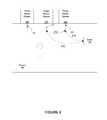
- FIG. 2shows a plurality of independently smart sensor systems 260 , 270 , 280 within a structure 100 , according to an embodiment.
- each of the smart sensor systems 260 , 270 , 280includes an antenna 261 , 271 , 281 .
- the antenna of at least one of the smart sensor systems 260 , 270 , 271includes a memory metal, and the antenna extends into the room or structure in which the at least one of the smart sensor systems 260 , 270 , 271 is located.
- wireless communication links between the at least one of the smart sensor systems 260 , 270 , 271 and another deviceis more likely to include a direct line of site (LOS). That is, obstructions to the wireless communication links are less likely to occur because the antennas 161 , 171 , 181 extend into the structure.
- the direct LOS pathgenerally provides a higher-quality communications link that a non-direct LOS path. That is, if the smart sensor systems 260 , 270 , 280 were configured such that the antenna did not extend into the structure, the communications links formed by the corresponding antennas would not be as good.
- a direct LOS communication link 210is formed between, for example, the smart sensor system 270 and a device 290 .
- a direct LOS communication link 212is formed between, for example, a first smart sensor system 270 and a second smart sensor system 260 .
- a direct LOS communications link 214is formed between the second smart sensor system 260 and the device 290 .
- FIG. 3shows an independently controllable light fixture 300 , according to another embodiment.
- a transceiver 312includes at least the communication interface 150 , and communicates with other devices through the antenna 314 .
- the transceiver 312is included within a structure (such as, structure 200 of FIG. 2 ) of the independently controllable light fixture 300 .
- the antenna 314extends into a room or structure in which the independently controllable light fixture 300 is located.
- the antenna 314extends through a ceiling of the room or structure.
- the antenna 314is fabricated out of a memory metal that is able to maintain its extended shape characteristics even when temporarily deformed. For example, when the independently controllable light fixture 300 is placed in a box for shipping, the antenna 314 may be deformed to allow the independently controllable light fixture 300 to fit within a shipping box or container. When the independently controllable light fixture 300 is removed from the box or container after shipping, the antenna 314 extends back to its desired position relative to the rest of the independently controllable light fixture 300 .
- the antenna 314includes a single strand of memory metal.
- the antenna 314includes more than a single strand of memory metal, but retains the memory function of returning to its intended original shape after being deformed for some period of time.
- the antenna 314is deformed to the position 320 .
- the memory metal of the antenna 314causes the antenna to spring back (indicated by arrow 330 ) to its original or deployed operating position. Owing to the antenna 314 being manufactured out of the memory metal, the light fixture 300 is easier to package and ship, while still maintaining a configuration that is adapted to forming the desired LOS communication links when deployed.
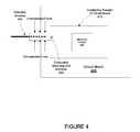
- FIG. 4shows a circuit board 400 of a building control sensor unit that includes a memory metal antenna 440 electrically connected to the circuit board 400 , according to an embodiment.
- the memory metal antennaare formed from materials that cannot be easily soldered to. That is, the memory metal antenna does not “wet” when solder is placed in contact with a heated memory metal antenna. Due to the fact that these memory metal antennas can be very difficult to solder to, placing them in electrical contact with electrical components on the circuit board 400 can be difficult.
- An embodimentincludes electrically connecting the memory metal antenna 440 to the circuit board through a conductive receiving unit interface 420 .
- the memory metal antenna 440is inserted into the conductive receiving unit interface 420 , and electrical contact between the memory metal antenna 440 and the conductive receiving unit interface 420 is realized by compressing the conductive receiving unit interface 420 around the memory metal antenna 420 .
- the conductive receiving unit interface 420can be realized using many different shapes, as long as electrical and mechanical contact of the memory metal antenna 440 is realized when the conductive receiving unit interface 420 is compressed around or onto the memory metal antenna 440 .
- the conductive receiving unit interface 420includes a conductive tube that the memory metal antenna 440 is inserted into, and the conductive tube is compressed to form a solid electrical and mechanical connection with the memory metal antenna 440 .
- the conductive receiving unit interface 420include “wings” that extend out for receiving the memory metal antenna, and are the compressed around the memory metal antenna 440 to form a solid electrical and mechanical connection with the memory metal antenna 440 .
- the “wings”are formed as a result of the compression of the conductive receiving unit interface 420 .
- the conductive receiving unit interface 420is electrically connected to, for example, a conductive trace 410 of the circuit board.
- the memory metal antenna 440is electrically connected to electronic circuits 430 of the circuit board 400 .
- the memory metal antenna 440is electrically connected to the circuit board 400 of the building control sensor unit.
- the building control sensor unitis enclosed within a metallic enclosure, and the extended antenna extends out of the metallic enclosure and into the structure.
- the extended antennais functional to deform from an operational position during shipping of the building control sensor unit, and spring back to the operational position when deployed for operation.
- the memory metal of the extended antennaincludes a Nickel Titanium alloy also known as Nitinol or NiTi.
- the extended antennaincludes a single strand of memory metal.
- the extended antennaincludes multiple strands, and other memory metal antenna configurations.
- the strand of memory metalcomprises a diameter of approximately 0.1 Millimeter.
- the memory metalcomprises a diameter of approximately 0.1 Millimeter, plus or minus approximately 0.05 Millimeters.
- FIG. 5shows an example of a plurality of independently controlled light fixtures 521 , 522 , 523 , 524 , 525 , 526 that are interfaced with a central controller 510 .
- a gateway 520is included within a communications path (second communication link) between the central controller 510 and the plurality of fixtures 522 , 523 , 524 , 525 , 526 .
- the central controller 510can initially provide each of the plurality of fixtures 522 , 523 , 524 , 525 , 526 with a light profile.
- the independently controlled lightscan include any number of sensors.
- the sensorscan include, for example, a light sensor, a motion sensor, a temperature sensor, a camera, and/or an air quality sensor.
- Information obtained from the sensorscan be used directly by the independently controlled light itself, or at least some of the information can be fed back to the central controller 510 , through, for example, a gateway 520 .
- a plurality of the fixturescan be included within a logical group.
- a user devicecan establish a direct communication link with any one of the fixtures. If the fixture is within a logical group, the user device can then control fixtures within the logical group by sending control information to the central controller 510 . The controller can then control the fixtures of the logical group through communications through the communications link.
- Various embodimentsinclude logical groups of fixtures that map onto, for example, a large conference room or a presentation hall.
- a user's direct communication link with any one of the fixtures within the conference room or presentation hallprovides the user with access to a logical switch capable of controlling the entire space with preset scenes etc. That is, by accessing the logical switch through a direct link to any one of the fixtures of the logical group, the user can control the logical group.
- the logical switchis configured by software operating on the fixtures (CPU of the high-voltage manager and/or CPU of the building control sensor unit) and/or the central controller.
- the control of the logical switch offered to the userincludes selection of an intensity of light of the logical group, and/or the selection of predetermined scenes associated with the logical group.
- the logical groupsare automatically determined by each of the fixtures (that is, building control sensor units of the fixtures) sensing other proximate fixtures. This can be accomplished, for example, by proximate fixtures sensing motion or light intensity changes simultaneously. That is, due to their proximity, they sense changes near-simultaneously.
Landscapes
- Physics & Mathematics (AREA)
- General Physics & Mathematics (AREA)
- General Health & Medical Sciences (AREA)
- Chemical & Material Sciences (AREA)
- Analytical Chemistry (AREA)
- Biochemistry (AREA)
- Life Sciences & Earth Sciences (AREA)
- Health & Medical Sciences (AREA)
- Immunology (AREA)
- Pathology (AREA)
- Spectroscopy & Molecular Physics (AREA)
- Engineering & Computer Science (AREA)
- Computer Networks & Wireless Communication (AREA)
- Circuit Arrangement For Electric Light Sources In General (AREA)
Abstract
Description
Claims (20)
Priority Applications (1)
| Application Number | Priority Date | Filing Date | Title |
|---|---|---|---|
| US14/596,496US9304051B2 (en) | 2010-08-03 | 2015-01-14 | Smart sensor unit with memory metal antenna |
Applications Claiming Priority (4)
| Application Number | Priority Date | Filing Date | Title |
|---|---|---|---|
| US12/849,081US8508149B2 (en) | 2010-08-03 | 2010-08-03 | Intelligent light retrofit |
| US13/930,009US20130320859A1 (en) | 2010-08-03 | 2013-06-28 | Intelligent light retrofit |
| US201461934008P | 2014-01-31 | 2014-01-31 | |
| US14/596,496US9304051B2 (en) | 2010-08-03 | 2015-01-14 | Smart sensor unit with memory metal antenna |
Related Parent Applications (1)
| Application Number | Title | Priority Date | Filing Date |
|---|---|---|---|
| US13/930,009Continuation-In-PartUS20130320859A1 (en) | 2010-08-03 | 2013-06-28 | Intelligent light retrofit |
Publications (2)
| Publication Number | Publication Date |
|---|---|
| US20150127260A1 US20150127260A1 (en) | 2015-05-07 |
| US9304051B2true US9304051B2 (en) | 2016-04-05 |
Family
ID=53007632
Family Applications (1)
| Application Number | Title | Priority Date | Filing Date |
|---|---|---|---|
| US14/596,496ActiveUS9304051B2 (en) | 2010-08-03 | 2015-01-14 | Smart sensor unit with memory metal antenna |
Country Status (1)
| Country | Link |
|---|---|
| US (1) | US9304051B2 (en) |
Families Citing this family (6)
| Publication number | Priority date | Publication date | Assignee | Title |
|---|---|---|---|---|
| US9961750B2 (en) | 2016-02-24 | 2018-05-01 | Leviton Manufacturing Co., Inc. | Advanced networked lighting control system including improved systems and methods for automated self-grouping of lighting fixtures |
| US9967957B2 (en)* | 2016-05-02 | 2018-05-08 | David R. Hall | Wireless rail with dynamic lighting |
| US10374282B2 (en) | 2016-07-19 | 2019-08-06 | Abl Ip Holding Llc | RF connector and antenna assembly for control devices, for example, for control of or inclusion in a luminaire |
| US10403959B2 (en) | 2016-07-19 | 2019-09-03 | Abl Ip Holding Llc | Thin wire antenna for control devices, for example, for control of or inclusion in a luminaire |
| US10080274B2 (en) | 2016-09-09 | 2018-09-18 | Abl Ip Holding Llc | Control modules having integral antenna components for luminaires and wireless intelligent lighting systems containing the same |
| WO2020040850A1 (en)* | 2018-08-21 | 2020-02-27 | Avx Antenna Inc. D/B/A Ethertronics Inc. | High performance antennas for smart appliances |
Citations (47)
| Publication number | Priority date | Publication date | Assignee | Title |
|---|---|---|---|---|
| US5101141A (en) | 1987-12-08 | 1992-03-31 | Legrand Electric Limited | Lighting control |
| US5179324A (en) | 1991-01-21 | 1993-01-12 | Legrand | Dimmer with reduced filtering losses |
| US5191265A (en) | 1991-08-09 | 1993-03-02 | Lutron Electronics Co., Inc. | Wall mounted programmable modular control system |
| US5283516A (en) | 1993-02-24 | 1994-02-01 | Pass & Seymour Legrand | Low voltage dimmer with no load protection |
| US5385297A (en)* | 1991-10-01 | 1995-01-31 | American Standard Inc. | Personal comfort system |
| US5553006A (en)* | 1994-06-09 | 1996-09-03 | Chelsea Group Ltd. | Method and apparatus for building environmental compliance |
| US5812422A (en) | 1995-09-07 | 1998-09-22 | Philips Electronics North America Corporation | Computer software for optimizing energy efficiency of a lighting system for a target energy consumption level |
| US5970393A (en)* | 1997-02-25 | 1999-10-19 | Polytechnic University | Integrated micro-strip antenna apparatus and a system utilizing the same for wireless communications for sensing and actuation purposes |
| US6057654A (en) | 1998-05-14 | 2000-05-02 | Legrand | Method and apparatus for automatically controlling a lighting load |
| US6188181B1 (en) | 1998-08-25 | 2001-02-13 | Lutron Electronics Co., Inc. | Lighting control system for different load types |
| US6342994B1 (en) | 1997-12-12 | 2002-01-29 | Legrand | Protective device against excessive currents, in particular for resettable protection of a controlled switch |
| US6548967B1 (en)* | 1997-08-26 | 2003-04-15 | Color Kinetics, Inc. | Universal lighting network methods and systems |
| US20040002792A1 (en) | 2002-06-28 | 2004-01-01 | Encelium Technologies Inc. | Lighting energy management system and method |
| US20050169643A1 (en)* | 1997-01-02 | 2005-08-04 | Franklin Philip G. | Method and apparatus for the zonal transmission of data using building lighting fixtures |
| US20050280598A1 (en)* | 2004-06-21 | 2005-12-22 | Lutron Electronics Co., Inc. | Compact radio frequency transmitting and receiving antenna and control device employing same |
| US20060028997A1 (en)* | 2004-08-09 | 2006-02-09 | Mcfarland Norman R | Wireless building control architecture |
| US20060273970A1 (en)* | 2005-06-06 | 2006-12-07 | Lutron Electronics Co., Inc. | Load control device having a compact antenna |
| US20070057807A1 (en) | 2005-09-12 | 2007-03-15 | Acuity Brands, Inc. | Activation device for an intelligent luminaire manager |
| US20070086128A1 (en) | 2004-09-28 | 2007-04-19 | Acuity Brands, Inc. | Equipment and methods for emergency lighting that provides brownout detection and protection |
| US20070215794A1 (en) | 2006-03-15 | 2007-09-20 | Honeywell International, Inc. | Light sensor and light sensing method |
| US7309985B2 (en) | 2003-04-23 | 2007-12-18 | Koninklijke Philips Electronics N. V. | Method of reconstructing an MR image |
| US7348736B2 (en)* | 2005-01-24 | 2008-03-25 | Philips Solid-State Lighting Solutions | Methods and apparatus for providing workspace lighting and facilitating workspace customization |
| US7382271B2 (en)* | 2004-09-29 | 2008-06-03 | Siemens Building Technologies, Inc. | Automated position detection for wireless building automation devices |
| US20080185977A1 (en) | 2004-12-14 | 2008-08-07 | Lutron Electronics Co., Inc. | Distributed intelligence ballast system and extended lighting control protocol |
| US20080244104A1 (en) | 2007-03-28 | 2008-10-02 | Johnson Controls Technology Company | Building automation system field devices and adapters |
| US7437596B2 (en)* | 2004-10-05 | 2008-10-14 | Siemens Building Technologies, Inc. | Self-healing control network for building automation systems |
| US20080265796A1 (en) | 2002-09-25 | 2008-10-30 | Jonathan Null | Light management system device and method |
| US20090026966A1 (en) | 2006-03-07 | 2009-01-29 | Koninklijke Philips Electronics N V | Lighting system with lighting units using optical communication |
| US20090140059A1 (en)* | 2007-11-30 | 2009-06-04 | Honeywell International Inc. | Hvac remote control unit and methods of operation |
| US7550931B2 (en)* | 2001-05-30 | 2009-06-23 | Philips Solid-State Lighting Solutions, Inc. | Controlled lighting methods and apparatus |
| US20090179596A1 (en) | 2006-05-11 | 2009-07-16 | Koninklijke Philips Electronics N V | Integrated lighting control module and power switch |
| US7566137B2 (en) | 2003-03-24 | 2009-07-28 | Lutron Electronics Co., Inc. | System to control daylight and electric light in a space |
| US7623042B2 (en) | 2005-03-14 | 2009-11-24 | Regents Of The University Of California | Wireless network control for building lighting system |
| US20100034386A1 (en) | 2008-08-06 | 2010-02-11 | Daintree Networks, Pty. Ltd. | Device manager repository |
| US20100135186A1 (en) | 2005-01-24 | 2010-06-03 | Daintree Networks, Pty. Ltd. | Network Analysis System and Method |
| US20100150060A1 (en)* | 2008-12-17 | 2010-06-17 | Vitek Clark A | Sensing device orientation in wireless networks |
| US7812543B2 (en) | 2006-11-15 | 2010-10-12 | Budike Jr Lothar E S | Modular wireless lighting control system using a common ballast control interface |
| US20100264846A1 (en) | 2008-04-14 | 2010-10-21 | Digital Lumens, Inc. | Power Management Unit with Adaptive Dimming |
| US20100270933A1 (en) | 2008-04-14 | 2010-10-28 | Digital Lumens, Inc. | Power Management Unit with Power Metering |
| US20100280677A1 (en) | 2009-05-04 | 2010-11-04 | Budike Jr Lothar E S | Lighting and energy control system and modules |
| US20100295482A1 (en) | 2009-04-14 | 2010-11-25 | Digital Lumens, Inc. | Power Management Unit with Multi-Input Arbitration |
| US20100301777A1 (en) | 2007-09-07 | 2010-12-02 | Regine Kraemer | Method and Device For Adjusting the Color or Photometric Properties of an Led Illumination Device |
| US20110031897A1 (en) | 2009-08-10 | 2011-02-10 | Redwood Systems, Inc. | Lighting systems and methods of auto-commissioning |
| US7925384B2 (en) | 2008-06-02 | 2011-04-12 | Adura Technologies, Inc. | Location-based provisioning of wireless control systems |
| US20110199020A1 (en) | 2010-02-18 | 2011-08-18 | Redwood Systems, Inc. | Methods of commissioning lighting systems |
| US20110210843A1 (en)* | 2010-03-01 | 2011-09-01 | Andrew Llc | System and method for location of mobile devices in confined environments |
| US20130285544A1 (en)* | 2012-04-30 | 2013-10-31 | Danny J. Molezion | Method and apparatus for radio-frequency controllable led lamp fixture antenna |
- 2015
- 2015-01-14USUS14/596,496patent/US9304051B2/enactiveActive
Patent Citations (51)
| Publication number | Priority date | Publication date | Assignee | Title |
|---|---|---|---|---|
| US5101141A (en) | 1987-12-08 | 1992-03-31 | Legrand Electric Limited | Lighting control |
| US5179324A (en) | 1991-01-21 | 1993-01-12 | Legrand | Dimmer with reduced filtering losses |
| US5191265A (en) | 1991-08-09 | 1993-03-02 | Lutron Electronics Co., Inc. | Wall mounted programmable modular control system |
| US5385297A (en)* | 1991-10-01 | 1995-01-31 | American Standard Inc. | Personal comfort system |
| US5283516A (en) | 1993-02-24 | 1994-02-01 | Pass & Seymour Legrand | Low voltage dimmer with no load protection |
| US5553006A (en)* | 1994-06-09 | 1996-09-03 | Chelsea Group Ltd. | Method and apparatus for building environmental compliance |
| US5812422A (en) | 1995-09-07 | 1998-09-22 | Philips Electronics North America Corporation | Computer software for optimizing energy efficiency of a lighting system for a target energy consumption level |
| US20060275040A1 (en) | 1997-01-02 | 2006-12-07 | Franklin Philip G | Method and apparatus for the zonal transmission of data using building lighting fixtures |
| US20050169643A1 (en)* | 1997-01-02 | 2005-08-04 | Franklin Philip G. | Method and apparatus for the zonal transmission of data using building lighting fixtures |
| US5970393A (en)* | 1997-02-25 | 1999-10-19 | Polytechnic University | Integrated micro-strip antenna apparatus and a system utilizing the same for wireless communications for sensing and actuation purposes |
| US6548967B1 (en)* | 1997-08-26 | 2003-04-15 | Color Kinetics, Inc. | Universal lighting network methods and systems |
| US6342994B1 (en) | 1997-12-12 | 2002-01-29 | Legrand | Protective device against excessive currents, in particular for resettable protection of a controlled switch |
| US6057654A (en) | 1998-05-14 | 2000-05-02 | Legrand | Method and apparatus for automatically controlling a lighting load |
| US6188181B1 (en) | 1998-08-25 | 2001-02-13 | Lutron Electronics Co., Inc. | Lighting control system for different load types |
| US7550931B2 (en)* | 2001-05-30 | 2009-06-23 | Philips Solid-State Lighting Solutions, Inc. | Controlled lighting methods and apparatus |
| US20040002792A1 (en) | 2002-06-28 | 2004-01-01 | Encelium Technologies Inc. | Lighting energy management system and method |
| US20070061050A1 (en) | 2002-06-28 | 2007-03-15 | Encelium Technologies Inc. | Lighting energy management system and method |
| US20080265796A1 (en) | 2002-09-25 | 2008-10-30 | Jonathan Null | Light management system device and method |
| US7566137B2 (en) | 2003-03-24 | 2009-07-28 | Lutron Electronics Co., Inc. | System to control daylight and electric light in a space |
| US7309985B2 (en) | 2003-04-23 | 2007-12-18 | Koninklijke Philips Electronics N. V. | Method of reconstructing an MR image |
| US20050280598A1 (en)* | 2004-06-21 | 2005-12-22 | Lutron Electronics Co., Inc. | Compact radio frequency transmitting and receiving antenna and control device employing same |
| US20060028997A1 (en)* | 2004-08-09 | 2006-02-09 | Mcfarland Norman R | Wireless building control architecture |
| US20090195161A1 (en) | 2004-09-28 | 2009-08-06 | Acuity Brands, Inc. | Equipment and methods for emergency lighting that provides brownout detection and protection |
| US20070086128A1 (en) | 2004-09-28 | 2007-04-19 | Acuity Brands, Inc. | Equipment and methods for emergency lighting that provides brownout detection and protection |
| US7382271B2 (en)* | 2004-09-29 | 2008-06-03 | Siemens Building Technologies, Inc. | Automated position detection for wireless building automation devices |
| US7437596B2 (en)* | 2004-10-05 | 2008-10-14 | Siemens Building Technologies, Inc. | Self-healing control network for building automation systems |
| US20080185977A1 (en) | 2004-12-14 | 2008-08-07 | Lutron Electronics Co., Inc. | Distributed intelligence ballast system and extended lighting control protocol |
| US7348736B2 (en)* | 2005-01-24 | 2008-03-25 | Philips Solid-State Lighting Solutions | Methods and apparatus for providing workspace lighting and facilitating workspace customization |
| US7792956B2 (en) | 2005-01-24 | 2010-09-07 | Daintree Networks, Pty. Ltd. | Network analysis system and method |
| US20100135186A1 (en) | 2005-01-24 | 2010-06-03 | Daintree Networks, Pty. Ltd. | Network Analysis System and Method |
| US7623042B2 (en) | 2005-03-14 | 2009-11-24 | Regents Of The University Of California | Wireless network control for building lighting system |
| US20060273970A1 (en)* | 2005-06-06 | 2006-12-07 | Lutron Electronics Co., Inc. | Load control device having a compact antenna |
| US20070057807A1 (en) | 2005-09-12 | 2007-03-15 | Acuity Brands, Inc. | Activation device for an intelligent luminaire manager |
| US20090026966A1 (en) | 2006-03-07 | 2009-01-29 | Koninklijke Philips Electronics N V | Lighting system with lighting units using optical communication |
| US20070215794A1 (en) | 2006-03-15 | 2007-09-20 | Honeywell International, Inc. | Light sensor and light sensing method |
| US20090179596A1 (en) | 2006-05-11 | 2009-07-16 | Koninklijke Philips Electronics N V | Integrated lighting control module and power switch |
| US7812543B2 (en) | 2006-11-15 | 2010-10-12 | Budike Jr Lothar E S | Modular wireless lighting control system using a common ballast control interface |
| US20080244104A1 (en) | 2007-03-28 | 2008-10-02 | Johnson Controls Technology Company | Building automation system field devices and adapters |
| US20100301777A1 (en) | 2007-09-07 | 2010-12-02 | Regine Kraemer | Method and Device For Adjusting the Color or Photometric Properties of an Led Illumination Device |
| US20090140059A1 (en)* | 2007-11-30 | 2009-06-04 | Honeywell International Inc. | Hvac remote control unit and methods of operation |
| US20100264846A1 (en) | 2008-04-14 | 2010-10-21 | Digital Lumens, Inc. | Power Management Unit with Adaptive Dimming |
| US20100270933A1 (en) | 2008-04-14 | 2010-10-28 | Digital Lumens, Inc. | Power Management Unit with Power Metering |
| US7925384B2 (en) | 2008-06-02 | 2011-04-12 | Adura Technologies, Inc. | Location-based provisioning of wireless control systems |
| US20100034386A1 (en) | 2008-08-06 | 2010-02-11 | Daintree Networks, Pty. Ltd. | Device manager repository |
| US20100150060A1 (en)* | 2008-12-17 | 2010-06-17 | Vitek Clark A | Sensing device orientation in wireless networks |
| US20100295482A1 (en) | 2009-04-14 | 2010-11-25 | Digital Lumens, Inc. | Power Management Unit with Multi-Input Arbitration |
| US20100280677A1 (en) | 2009-05-04 | 2010-11-04 | Budike Jr Lothar E S | Lighting and energy control system and modules |
| US20110031897A1 (en) | 2009-08-10 | 2011-02-10 | Redwood Systems, Inc. | Lighting systems and methods of auto-commissioning |
| US20110199020A1 (en) | 2010-02-18 | 2011-08-18 | Redwood Systems, Inc. | Methods of commissioning lighting systems |
| US20110210843A1 (en)* | 2010-03-01 | 2011-09-01 | Andrew Llc | System and method for location of mobile devices in confined environments |
| US20130285544A1 (en)* | 2012-04-30 | 2013-10-31 | Danny J. Molezion | Method and apparatus for radio-frequency controllable led lamp fixture antenna |
Also Published As
| Publication number | Publication date |
|---|---|
| US20150127260A1 (en) | 2015-05-07 |
Similar Documents
| Publication | Publication Date | Title |
|---|---|---|
| US9304051B2 (en) | Smart sensor unit with memory metal antenna | |
| US8508149B2 (en) | Intelligent light retrofit | |
| US9943042B2 (en) | Grow light embodying power delivery and data communications features | |
| US8994295B2 (en) | Commission of distributed light fixtures of a lighting system | |
| CN103283311B (en) | Wireless Adaptation of Lighting Power | |
| US8604714B2 (en) | Lighting control | |
| CN102860133B (en) | Bull switch device and system | |
| CN104823523B (en) | Distributed Lighting Control | |
| US9226371B2 (en) | User control of an environmental parameter of a structure | |
| US10517163B2 (en) | Power receptacle control circuitry | |
| US10076016B2 (en) | Network connected low voltage lighting system | |
| EP2986084A1 (en) | Led lighting device and led lighting control system | |
| EP2494850B1 (en) | Method for operating a lighting grid and lighting unit for use in a lighting grid | |
| US9078305B2 (en) | Distributed lighting control that includes satellite control units | |
| US10636290B2 (en) | Communication interface device for a solid-state luminaire | |
| JP2009205841A (en) | Illumination control system | |
| JP6846665B2 (en) | lighting equipment | |
| US10448487B2 (en) | Driver module for powering a light source and a further module | |
| CN101958742B (en) | Relay forwarding control system and wireless control device for high current assembly | |
| CN202756971U (en) | Light emitting diode (LED) light and LED lighting network system | |
| EP2973885B1 (en) | Wireless connector node and system | |
| EP3393209B1 (en) | A system for regulating the minimum output current of an led dimming power supply | |
| US20250098043A1 (en) | Low-voltage lighting systems and methods | |
| US20150303698A1 (en) | System and method for home automation using power interruption and duration | |
| HK1180522A (en) | Lighting control switch apparatus and system |
Legal Events
| Date | Code | Title | Description |
|---|---|---|---|
| AS | Assignment | Owner name:ENLIGHTED, INC., CALIFORNIA Free format text:ASSIGNMENT OF ASSIGNORS INTEREST;ASSIGNORS:MULLER, PETER H.;BILLARD, MICHEL;MOHAN, TANUJ;SIGNING DATES FROM 20150106 TO 20150113;REEL/FRAME:034706/0963 | |
| AS | Assignment | Owner name:PACIFIC WESTERN BANK, NORTH CAROLINA Free format text:SECURITY INTEREST;ASSIGNOR:ENLIGHTED, INC.;REEL/FRAME:037631/0651 Effective date:20160122 | |
| STCF | Information on status: patent grant | Free format text:PATENTED CASE | |
| FEPP | Fee payment procedure | Free format text:ENTITY STATUS SET TO UNDISCOUNTED (ORIGINAL EVENT CODE: BIG.); ENTITY STATUS OF PATENT OWNER: LARGE ENTITY | |
| MAFP | Maintenance fee payment | Free format text:PAYMENT OF MAINTENANCE FEE, 4TH YEAR, LARGE ENTITY (ORIGINAL EVENT CODE: M1551); ENTITY STATUS OF PATENT OWNER: LARGE ENTITY Year of fee payment:4 | |
| AS | Assignment | Owner name:BUILDING ROBOTICS, INC., CALIFORNIA Free format text:MERGER;ASSIGNOR:ENLIGHTED, INC.;REEL/FRAME:057883/0238 Effective date:20210929 | |
| MAFP | Maintenance fee payment | Free format text:PAYMENT OF MAINTENANCE FEE, 8TH YEAR, LARGE ENTITY (ORIGINAL EVENT CODE: M1552); ENTITY STATUS OF PATENT OWNER: LARGE ENTITY Year of fee payment:8 |