US9304042B2 - Foreign object detection system and method suitable for source resonator of wireless energy transfer system - Google Patents
Foreign object detection system and method suitable for source resonator of wireless energy transfer systemDownload PDFInfo
- Publication number
- US9304042B2 US9304042B2US13/744,618US201313744618AUS9304042B2US 9304042 B2US9304042 B2US 9304042B2US 201313744618 AUS201313744618 AUS 201313744618AUS 9304042 B2US9304042 B2US 9304042B2
- Authority
- US
- United States
- Prior art keywords
- thermal
- camera
- intensity
- source resonator
- map
- Prior art date
- Legal status (The legal status is an assumption and is not a legal conclusion. Google has not performed a legal analysis and makes no representation as to the accuracy of the status listed.)
- Active, expires
Links
Images


Classifications
- G—PHYSICS
- G01—MEASURING; TESTING
- G01J—MEASUREMENT OF INTENSITY, VELOCITY, SPECTRAL CONTENT, POLARISATION, PHASE OR PULSE CHARACTERISTICS OF INFRARED, VISIBLE OR ULTRAVIOLET LIGHT; COLORIMETRY; RADIATION PYROMETRY
- G01J5/00—Radiation pyrometry, e.g. infrared or optical thermometry
- G01J5/0022—Radiation pyrometry, e.g. infrared or optical thermometry for sensing the radiation of moving bodies
- B60L11/182—
- B60L11/1824—
- B60L11/1833—
- B60L11/1835—
- B—PERFORMING OPERATIONS; TRANSPORTING
- B60—VEHICLES IN GENERAL
- B60L—PROPULSION OF ELECTRICALLY-PROPELLED VEHICLES; SUPPLYING ELECTRIC POWER FOR AUXILIARY EQUIPMENT OF ELECTRICALLY-PROPELLED VEHICLES; ELECTRODYNAMIC BRAKE SYSTEMS FOR VEHICLES IN GENERAL; MAGNETIC SUSPENSION OR LEVITATION FOR VEHICLES; MONITORING OPERATING VARIABLES OF ELECTRICALLY-PROPELLED VEHICLES; ELECTRIC SAFETY DEVICES FOR ELECTRICALLY-PROPELLED VEHICLES
- B60L53/00—Methods of charging batteries, specially adapted for electric vehicles; Charging stations or on-board charging equipment therefor; Exchange of energy storage elements in electric vehicles
- B60L53/10—Methods of charging batteries, specially adapted for electric vehicles; Charging stations or on-board charging equipment therefor; Exchange of energy storage elements in electric vehicles characterised by the energy transfer between the charging station and the vehicle
- B60L53/12—Inductive energy transfer
- B60L53/124—Detection or removal of foreign bodies
- B—PERFORMING OPERATIONS; TRANSPORTING
- B60—VEHICLES IN GENERAL
- B60L—PROPULSION OF ELECTRICALLY-PROPELLED VEHICLES; SUPPLYING ELECTRIC POWER FOR AUXILIARY EQUIPMENT OF ELECTRICALLY-PROPELLED VEHICLES; ELECTRODYNAMIC BRAKE SYSTEMS FOR VEHICLES IN GENERAL; MAGNETIC SUSPENSION OR LEVITATION FOR VEHICLES; MONITORING OPERATING VARIABLES OF ELECTRICALLY-PROPELLED VEHICLES; ELECTRIC SAFETY DEVICES FOR ELECTRICALLY-PROPELLED VEHICLES
- B60L53/00—Methods of charging batteries, specially adapted for electric vehicles; Charging stations or on-board charging equipment therefor; Exchange of energy storage elements in electric vehicles
- B60L53/30—Constructional details of charging stations
- B60L53/35—Means for automatic or assisted adjustment of the relative position of charging devices and vehicles
- B60L53/36—Means for automatic or assisted adjustment of the relative position of charging devices and vehicles by positioning the vehicle
- B—PERFORMING OPERATIONS; TRANSPORTING
- B60—VEHICLES IN GENERAL
- B60L—PROPULSION OF ELECTRICALLY-PROPELLED VEHICLES; SUPPLYING ELECTRIC POWER FOR AUXILIARY EQUIPMENT OF ELECTRICALLY-PROPELLED VEHICLES; ELECTRODYNAMIC BRAKE SYSTEMS FOR VEHICLES IN GENERAL; MAGNETIC SUSPENSION OR LEVITATION FOR VEHICLES; MONITORING OPERATING VARIABLES OF ELECTRICALLY-PROPELLED VEHICLES; ELECTRIC SAFETY DEVICES FOR ELECTRICALLY-PROPELLED VEHICLES
- B60L53/00—Methods of charging batteries, specially adapted for electric vehicles; Charging stations or on-board charging equipment therefor; Exchange of energy storage elements in electric vehicles
- B60L53/30—Constructional details of charging stations
- B60L53/35—Means for automatic or assisted adjustment of the relative position of charging devices and vehicles
- B60L53/37—Means for automatic or assisted adjustment of the relative position of charging devices and vehicles using optical position determination, e.g. using cameras
- G—PHYSICS
- G01—MEASURING; TESTING
- G01J—MEASUREMENT OF INTENSITY, VELOCITY, SPECTRAL CONTENT, POLARISATION, PHASE OR PULSE CHARACTERISTICS OF INFRARED, VISIBLE OR ULTRAVIOLET LIGHT; COLORIMETRY; RADIATION PYROMETRY
- G01J3/00—Spectrometry; Spectrophotometry; Monochromators; Measuring colours
- G01J3/46—Measurement of colour; Colour measuring devices, e.g. colorimeters
- G01J3/463—Colour matching
- G—PHYSICS
- G01—MEASURING; TESTING
- G01J—MEASUREMENT OF INTENSITY, VELOCITY, SPECTRAL CONTENT, POLARISATION, PHASE OR PULSE CHARACTERISTICS OF INFRARED, VISIBLE OR ULTRAVIOLET LIGHT; COLORIMETRY; RADIATION PYROMETRY
- G01J3/00—Spectrometry; Spectrophotometry; Monochromators; Measuring colours
- G01J3/46—Measurement of colour; Colour measuring devices, e.g. colorimeters
- G01J3/50—Measurement of colour; Colour measuring devices, e.g. colorimeters using electric radiation detectors
- G—PHYSICS
- G01—MEASURING; TESTING
- G01J—MEASUREMENT OF INTENSITY, VELOCITY, SPECTRAL CONTENT, POLARISATION, PHASE OR PULSE CHARACTERISTICS OF INFRARED, VISIBLE OR ULTRAVIOLET LIGHT; COLORIMETRY; RADIATION PYROMETRY
- G01J5/00—Radiation pyrometry, e.g. infrared or optical thermometry
- G01J5/0022—Radiation pyrometry, e.g. infrared or optical thermometry for sensing the radiation of moving bodies
- G01J5/0025—Living bodies
- G—PHYSICS
- G01—MEASURING; TESTING
- G01J—MEASUREMENT OF INTENSITY, VELOCITY, SPECTRAL CONTENT, POLARISATION, PHASE OR PULSE CHARACTERISTICS OF INFRARED, VISIBLE OR ULTRAVIOLET LIGHT; COLORIMETRY; RADIATION PYROMETRY
- G01J5/00—Radiation pyrometry, e.g. infrared or optical thermometry
- G01J5/02—Constructional details
- G01J5/08—Optical arrangements
- G01J5/0846—Optical arrangements having multiple detectors for performing different types of detection, e.g. using radiometry and reflectometry channels
- G—PHYSICS
- G01—MEASURING; TESTING
- G01J—MEASUREMENT OF INTENSITY, VELOCITY, SPECTRAL CONTENT, POLARISATION, PHASE OR PULSE CHARACTERISTICS OF INFRARED, VISIBLE OR ULTRAVIOLET LIGHT; COLORIMETRY; RADIATION PYROMETRY
- G01J5/00—Radiation pyrometry, e.g. infrared or optical thermometry
- G01J5/02—Constructional details
- G01J5/08—Optical arrangements
- G01J5/0859—Sighting arrangements, e.g. cameras
- G—PHYSICS
- G01—MEASURING; TESTING
- G01J—MEASUREMENT OF INTENSITY, VELOCITY, SPECTRAL CONTENT, POLARISATION, PHASE OR PULSE CHARACTERISTICS OF INFRARED, VISIBLE OR ULTRAVIOLET LIGHT; COLORIMETRY; RADIATION PYROMETRY
- G01J5/00—Radiation pyrometry, e.g. infrared or optical thermometry
- G01J5/02—Constructional details
- G01J5/08—Optical arrangements
- G01J5/0896—Optical arrangements using a light source, e.g. for illuminating a surface
- H02J5/005—
- H—ELECTRICITY
- H02—GENERATION; CONVERSION OR DISTRIBUTION OF ELECTRIC POWER
- H02J—CIRCUIT ARRANGEMENTS OR SYSTEMS FOR SUPPLYING OR DISTRIBUTING ELECTRIC POWER; SYSTEMS FOR STORING ELECTRIC ENERGY
- H02J50/00—Circuit arrangements or systems for wireless supply or distribution of electric power
- H02J50/10—Circuit arrangements or systems for wireless supply or distribution of electric power using inductive coupling
- H02J50/12—Circuit arrangements or systems for wireless supply or distribution of electric power using inductive coupling of the resonant type
- H—ELECTRICITY
- H02—GENERATION; CONVERSION OR DISTRIBUTION OF ELECTRIC POWER
- H02J—CIRCUIT ARRANGEMENTS OR SYSTEMS FOR SUPPLYING OR DISTRIBUTING ELECTRIC POWER; SYSTEMS FOR STORING ELECTRIC ENERGY
- H02J50/00—Circuit arrangements or systems for wireless supply or distribution of electric power
- H02J50/60—Circuit arrangements or systems for wireless supply or distribution of electric power responsive to the presence of foreign objects, e.g. detection of living beings
- B—PERFORMING OPERATIONS; TRANSPORTING
- B60—VEHICLES IN GENERAL
- B60L—PROPULSION OF ELECTRICALLY-PROPELLED VEHICLES; SUPPLYING ELECTRIC POWER FOR AUXILIARY EQUIPMENT OF ELECTRICALLY-PROPELLED VEHICLES; ELECTRODYNAMIC BRAKE SYSTEMS FOR VEHICLES IN GENERAL; MAGNETIC SUSPENSION OR LEVITATION FOR VEHICLES; MONITORING OPERATING VARIABLES OF ELECTRICALLY-PROPELLED VEHICLES; ELECTRIC SAFETY DEVICES FOR ELECTRICALLY-PROPELLED VEHICLES
- B60L2240/00—Control parameters of input or output; Target parameters
- B60L2240/10—Vehicle control parameters
- B60L2240/36—Temperature of vehicle components or parts
- B—PERFORMING OPERATIONS; TRANSPORTING
- B60—VEHICLES IN GENERAL
- B60L—PROPULSION OF ELECTRICALLY-PROPELLED VEHICLES; SUPPLYING ELECTRIC POWER FOR AUXILIARY EQUIPMENT OF ELECTRICALLY-PROPELLED VEHICLES; ELECTRODYNAMIC BRAKE SYSTEMS FOR VEHICLES IN GENERAL; MAGNETIC SUSPENSION OR LEVITATION FOR VEHICLES; MONITORING OPERATING VARIABLES OF ELECTRICALLY-PROPELLED VEHICLES; ELECTRIC SAFETY DEVICES FOR ELECTRICALLY-PROPELLED VEHICLES
- B60L2250/00—Driver interactions
- B60L2250/10—Driver interactions by alarm
- B—PERFORMING OPERATIONS; TRANSPORTING
- B60—VEHICLES IN GENERAL
- B60L—PROPULSION OF ELECTRICALLY-PROPELLED VEHICLES; SUPPLYING ELECTRIC POWER FOR AUXILIARY EQUIPMENT OF ELECTRICALLY-PROPELLED VEHICLES; ELECTRODYNAMIC BRAKE SYSTEMS FOR VEHICLES IN GENERAL; MAGNETIC SUSPENSION OR LEVITATION FOR VEHICLES; MONITORING OPERATING VARIABLES OF ELECTRICALLY-PROPELLED VEHICLES; ELECTRIC SAFETY DEVICES FOR ELECTRICALLY-PROPELLED VEHICLES
- B60L2270/00—Problem solutions or means not otherwise provided for
- B60L2270/10—Emission reduction
- B60L2270/14—Emission reduction of noise
- B60L2270/147—Emission reduction of noise electro magnetic [EMI]
- G—PHYSICS
- G01—MEASURING; TESTING
- G01V—GEOPHYSICS; GRAVITATIONAL MEASUREMENTS; DETECTING MASSES OR OBJECTS; TAGS
- G01V3/00—Electric or magnetic prospecting or detecting; Measuring magnetic field characteristics of the earth, e.g. declination, deviation
- G01V3/12—Electric or magnetic prospecting or detecting; Measuring magnetic field characteristics of the earth, e.g. declination, deviation operating with electromagnetic waves
- Y—GENERAL TAGGING OF NEW TECHNOLOGICAL DEVELOPMENTS; GENERAL TAGGING OF CROSS-SECTIONAL TECHNOLOGIES SPANNING OVER SEVERAL SECTIONS OF THE IPC; TECHNICAL SUBJECTS COVERED BY FORMER USPC CROSS-REFERENCE ART COLLECTIONS [XRACs] AND DIGESTS
- Y02—TECHNOLOGIES OR APPLICATIONS FOR MITIGATION OR ADAPTATION AGAINST CLIMATE CHANGE
- Y02T—CLIMATE CHANGE MITIGATION TECHNOLOGIES RELATED TO TRANSPORTATION
- Y02T10/00—Road transport of goods or passengers
- Y02T10/60—Other road transportation technologies with climate change mitigation effect
- Y02T10/70—Energy storage systems for electromobility, e.g. batteries
- Y02T10/7005—
- Y—GENERAL TAGGING OF NEW TECHNOLOGICAL DEVELOPMENTS; GENERAL TAGGING OF CROSS-SECTIONAL TECHNOLOGIES SPANNING OVER SEVERAL SECTIONS OF THE IPC; TECHNICAL SUBJECTS COVERED BY FORMER USPC CROSS-REFERENCE ART COLLECTIONS [XRACs] AND DIGESTS
- Y02—TECHNOLOGIES OR APPLICATIONS FOR MITIGATION OR ADAPTATION AGAINST CLIMATE CHANGE
- Y02T—CLIMATE CHANGE MITIGATION TECHNOLOGIES RELATED TO TRANSPORTATION
- Y02T10/00—Road transport of goods or passengers
- Y02T10/60—Other road transportation technologies with climate change mitigation effect
- Y02T10/7072—Electromobility specific charging systems or methods for batteries, ultracapacitors, supercapacitors or double-layer capacitors
- Y—GENERAL TAGGING OF NEW TECHNOLOGICAL DEVELOPMENTS; GENERAL TAGGING OF CROSS-SECTIONAL TECHNOLOGIES SPANNING OVER SEVERAL SECTIONS OF THE IPC; TECHNICAL SUBJECTS COVERED BY FORMER USPC CROSS-REFERENCE ART COLLECTIONS [XRACs] AND DIGESTS
- Y02—TECHNOLOGIES OR APPLICATIONS FOR MITIGATION OR ADAPTATION AGAINST CLIMATE CHANGE
- Y02T—CLIMATE CHANGE MITIGATION TECHNOLOGIES RELATED TO TRANSPORTATION
- Y02T90/00—Enabling technologies or technologies with a potential or indirect contribution to GHG emissions mitigation
- Y02T90/10—Technologies relating to charging of electric vehicles
- Y02T90/12—Electric charging stations
- Y02T90/121—
- Y02T90/122—
- Y02T90/125—
- Y—GENERAL TAGGING OF NEW TECHNOLOGICAL DEVELOPMENTS; GENERAL TAGGING OF CROSS-SECTIONAL TECHNOLOGIES SPANNING OVER SEVERAL SECTIONS OF THE IPC; TECHNICAL SUBJECTS COVERED BY FORMER USPC CROSS-REFERENCE ART COLLECTIONS [XRACs] AND DIGESTS
- Y02—TECHNOLOGIES OR APPLICATIONS FOR MITIGATION OR ADAPTATION AGAINST CLIMATE CHANGE
- Y02T—CLIMATE CHANGE MITIGATION TECHNOLOGIES RELATED TO TRANSPORTATION
- Y02T90/00—Enabling technologies or technologies with a potential or indirect contribution to GHG emissions mitigation
- Y02T90/10—Technologies relating to charging of electric vehicles
- Y02T90/14—Plug-in electric vehicles
Definitions
- This disclosuregenerally relates to foreign object detection in the vicinity of a source resonator in a wireless energy transfer system, and more particularly relates to a system and method to combine or fuse information from a visible light camera and a multiple zone temperature sensor to detect a foreign object proximate to the source resonator.
- Wireless energy transfer systemsare known to incorporate a first resonator structure (source resonator) that includes a coil configured for transferring magnetic energy and a spaced apart second resonator structure (capture resonator) that also includes a coil configured for receiving the wirelessly transmitted magnetic energy.
- a wireless energy transfer systemmay be used for electrically charging an energy storage device, such as battery of an electric or hybrid vehicle.
- the source resonatormay be located on, or embedded into, a surface for example the floor of a garage or the surface of a parking lot, and the capture resonator may be disposed on a vehicle.
- the vehicle to be chargedis parked so that the capture resonator is generally aligned above the source resonator.
- the source resonator and capture resonatorare separated by a distance that approximates a ground clearance of the vehicle which is a typical clearance between the bottom portion of the vehicle's chassis and a ground surface.
- the ground clearancemay be in a range from about 10 centimeters (cm) to 20 cm.
- the ground clearance space between the source resonator and capture resonatoris typically large enough to provide room for foreign objects such as aluminum soda cans or steel tools to reside on or near the source resonator.
- Metallic foreign objects such as these in the vicinity of the source resonatormay reduce the energy transfer efficiency of the resonators and may cause undesirable localized heating due to inductive heating of the foreign object.
- the space between the source resonator and capture resonatormay also be large enough to allow small animals, for instance dogs or cats, to come between the resonators. Having an animal between, or in close proximity to, the resonators when the wireless energy transfer system is operating may be a cause for concern. It may be desirable to monitor the source resonator and an area around the source resonator for foreign objects and to control the wireless energy transfer system to prevent or modify system operation when a foreign object is detected.
- Wireless energy transfer systemscapable of detecting foreign objects have been proposed, see United States Patent Application Number 2011/074346 filed Mar. 31, 2011 by Hall et al. These wireless energy transfer systems typically rely on detecting the heating of a foreign object caused by operation of the system.
- a system to detect a foreign object proximate to a source resonatorincludes a visible light camera mounted so as to have a camera field of view that includes the source resonator.
- the camerais configured to output image data indicative of visible light intensity detected by pixels in the camera.
- the cameramay have more than 100,000 pixels.
- the systemalso includes a multiple zone temperature sensor mounted so as to have a sensor field of view that includes the source resonator and is similar to the camera field of view.
- the sensoris configured to output thermal data indicative of a zone temperature for each of the multiple zones.
- the multiple zone temperature sensormay have fewer than 1000 zones.
- the systemfurther includes a controller configured to receive visible light image data from the camera, determine an intensity map characterized as an array of intensity data cells, designate an intensity object on an area of the intensity map, receive the thermal data from the multiple zone temperature sensor, determine a thermal map characterized as an array of thermal data cells, designate a thermal object on an area of the thermal map, detect the foreign object when the intensity object and the thermal object intersect, and control an electric current provided to the source resonator when the foreign object is detected.
- a controllerconfigured to receive visible light image data from the camera, determine an intensity map characterized as an array of intensity data cells, designate an intensity object on an area of the intensity map, receive the thermal data from the multiple zone temperature sensor, determine a thermal map characterized as an array of thermal data cells, designate a thermal object on an area of the thermal map, detect the foreign object when the intensity object and the thermal object intersect, and control an electric current provided to the source resonator when the foreign object is detected.
- the cameramay be further configured to output image data indicative of visible light color and the controller may be further configured to determine a hue map characterized as an array of hue data cells, designate a hue object on an area of the hue map, and detect the foreign object when the hue object, the intensity object, and the thermal object intersect.
- the controllermay be configured to determine a saturation map characterized as an array of saturation data cells, designate a saturation object on an area of the saturation map, and detect the foreign object when the saturation object, the intensity object, and the thermal object intersect.
- the visible light camera and the multiple zone temperature sensormay be mounted on an underside of a vehicle.
- the visible light camera and the multiple zone temperature sensormay be mounted in close proximity to a capture resonator.
- the systemmay further include a warning indicator coupled to the controller effective to generate a warning signal when the foreign object is detected.
- a method to detect a foreign object proximate to a source resonatoris provided.
- the detectionis based on image data from a visible light camera mounted so as to have a camera field of view that includes the source resonator and a multiple zone temperature sensor mounted so as to have a sensor field of view that includes the source resonator and is similar to the camera field of view.
- the methodincludes the steps of:
- the image datais indicative of visible light intensity detected by pixels in the camera.
- Each intensity data cellhas an intensity value based on an intensity characteristic of the image data detected by of one or more of the pixels.
- the thermal dataincludes a zone temperature value for each of the multiple zones.
- a thermal mapcharacterized as an array of thermal data cells. Each thermal data cell has a temperature value based on a temperature characteristic of one or more of the multiple zones. This step may include the additional steps of determining a background temperature value based on a zone temperature value of at least one zone, determining a differential temperature value for each zone based on a difference between the background temperature value and a corresponding zone temperature value, and generating a thermal binary map based on a comparison of the differential temperature value to a differential temperature threshold value.
- This stepmay include the additional step of determining that the detection of the foreign object persists for a time longer than a persistence time threshold.
- the method of detecting the foreign object proximate to the source resonatormay further include the steps of:
- hue mapcharacterized as an array of hue data cells.
- Each hue data cellhas a hue value based on a hue characteristic of the image data detected by of one or more of the pixels.
- hue data cells designated as the hue objectbased on one or more of a hue object shape and a hue object size.
- Each saturation data cellhas a saturation value based on a saturation characteristic of the image data detected by of one or more of the pixels.
- intensity data cells designated as the intensity objectIncreasing the number of intensity data cells designated as the intensity object based on one or more of an intensity object shape and an intensity object size.
- thermal data cells designated as the thermal objectIncreasing the number of thermal data cells designated as the thermal object based on one or more of a thermal object shape and a thermal object size.
- a controller for a systemconfigured to detect that a foreign object is proximate to a source resonator.
- the systemcomprises a visible light camera mounted so as to have a camera field of view that includes the source resonator.
- the camerais configured to output image data indicative of visible light intensity detected by pixels in the camera.
- the systemalso includes a multiple zone temperature sensor mounted so as to have a sensor field of view that includes the source resonator and is similar to the camera field of view.
- the sensoris configured to output thermal data indicative of a zone temperature for each of the multiple zones.
- the controlleris configured to receive visible light image data from the camera, determine an intensity map characterized as an array of intensity data cells, designate an intensity object on an area of the intensity map, receive the thermal data from the multiple zone temperature sensor, determine a thermal map characterized as an array of thermal data cells, designate a thermal object on an area of the thermal map, detect the foreign object when the intensity object and the thermal object intersect, and control an electric current provided to the source resonator when the foreign object is detected.
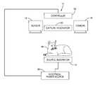
- FIG. 1is a diagram of system to detect a foreign object proximate to a source resonator in accordance with one embodiment
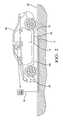
- FIG. 2is a side view of a vehicle equipped with the system of FIG. 1 in accordance with one embodiment
- FIG. 3is an illustration depicting an intensity map containing an intensity object of the system of FIG. 1 in accordance with one embodiment
- FIG. 4is an illustration depicting a reference intensity map of the system of FIG. 1 in accordance with one embodiment
- FIG. 5is an illustration depicting a thermal map containing a thermal object of the system of FIG. 1 in accordance with one embodiment
- FIG. 6is an illustration depicting the intersection of an intensity object and a thermal object of the system of FIG. 1 in accordance with one embodiment
- FIG. 7is diagram depicting an animal between a source resonator and a capture resonator of the system of FIG. 1 before the source resonator initiates energy transfer in accordance with one embodiment
- FIG. 8is diagram depicting a metallic foreign object between a source resonator and a capture resonator of the system of FIG. 1 after the source resonator initiates energy transfer in accordance with one embodiment
- FIG. 9is a flowchart of a method executed by the system of FIG. 1 in accordance with one embodiment.
- the system described hereinis configured to detect a foreign object on or near a source resonator that is part of a wireless energy transfer system.
- the systemincludes a visible light camera that is mounted to provide a camera field of view that includes the source resonator within the camera field of view.
- the camerais in communication with a controller that is configured to visibly identify objects that may be foreign objects based on image data from the camera.
- the systemalso includes a multiple zone temperature sensor that is mounted to provide a sensor field of view that includes the source resonator within the sensor field of view.
- the sensor field of viewmay be similar to the camera field of view.
- the sensoris also in communication with the controller.
- the controlleris configured to identify thermal objects that may be foreign objects based on thermal data from the sensor.
- the controllermay determine that a foreign object is on or near the source resonator and the controller may control the electrical current supplied to the source resonator to inhibit, suspend, or reduce the energy emitted by the source resonator.
- FIG. 1illustrates a non-limiting example of a system 10 generally configured to detect that a foreign object 12 , for example a metallic wrench, is proximate to a source resonator 14 .
- the system 10includes a visible light camera 16 and a multiple zone temperature sensor 18 .
- the visible light camera 16is a digital imaging device that is most sensitive to electromagnetic energy with a wavelength in the visible light spectrum (390 nanometer (nm) to 750 nm).
- the visible light camera 16hereinafter the camera 16 , is generally configured to output image data indicative of visible light intensity (e.g. monochrome image data) detected by pixels (not shown) in the camera field of view 20 .
- the camera 16may be additionally configured to output image data indicative of visible light color, for example hue and saturation (e.g. multi-chromatic image or full color image data).
- a suitable resolution for the camera 16may be provided by a pixel array characterized as 640 by 480 for a total of 307,200 pixels. Cameras of higher and lower resolution are commercially available from a wide variety of sources. The camera 16 needs to have sufficient resolution so when the image data is analyzed, there is sufficient detail to discern an object near or on the source resonator 14 .
- the multiple zone temperature sensor 18is a device that is most sensitive to electromagnetic energy with a wavelength in the infrared (IR) spectrum (750 nm to 1000 nm).
- the multiple zone temperature sensor 18hereafter the sensor 18 , is generally configured to output thermal data indicative of a zone temperature for each individual zone of the multiple zones in a sensor field of view 22 .
- the individual zonesmay each be relatively small regions that may result in detection gaps between the individual zones, or the zones may be sized and shaped so most or all locations in the sensor field of view 22 are covered by one of the individual zones, or the zones may be sized and shaped so there is some overlap of the individual zones so some locations are covered by more than one of the individual zones.
- the multiple zone temperature sensor 18may include an IR imaging camera that provides a resolution similar to that of the visible light camera 16 .
- the sensor 18may include an array of a plurality of thermopile sensors, such as those available from Heimann Sensor GmbH located in Dresden, Germany.
- a suitable resolution for the sensor 18may be provided by a thermopile array of 32 by 31 thermopiles that may be configured to view 992 distinct temperature zones in the sensor field of view 22 .
- Using such arrays of thermopile sensors instead of an IR cameramay be preferred to keep the cost of the system 10 low, an important factor for automotive applications.
- the camera 16 and the sensor 18are mounted on the underside 24 of the vehicle 26 in order to have a camera field of view 20 and a sensor field of view 22 that may include the source resonator 14 when the source resonator 14 in located on, or embedded in, a parking surface 28 .
- the camera field of view 20is directed beneath the vehicle 26 .
- the system 10could be configured with a camera 16 and a sensor 18 mounted in a location to detect a foreign object 12 when the source resonator 14 is beside or in front of the vehicle 26 .
- the senor 18is mounted on the underside 24 of vehicle 26 in order to have a sensor field of view 22 that may include the source resonator 14 .
- the camera 16 and the sensor 18are illustrated as being substantially separated only for the purpose of illustration. It is recognized that the camera 16 and the sensor 18 are preferably co-located so that both have essentially the same field of view 20 , 22 .
- the camera 16 and sensor 18may be located in close proximity to a capture resonator 30 in order to provide a camera field of view 20 and a sensor field of view 22 that includes the source resonator 14 when the capture resonator 30 and source resonator 14 are properly aligned for wireless energy transfer.
- the camera 16 and the sensor 18may be incorporated into a single housing that also contains the capture resonator 30 . If the camera 16 and sensor 18 are separated, known image processing techniques may be used to transform the apparent fields of view 20 , 22 to substantially correspond. As used herein, having the sensor field of view 22 similar to the camera field of view 20 means that if the source resonator 14 is present in one field of view 20 at a location where the vehicle 26 may be over the source resonator 14 , the source resonator 14 is also present in the other field of view 22 .
- the system 10includes a controller 32 configured to receive the image data characterized as visible light image data from the camera 16 .
- the image datais indicative of visible light intensity of the scene in the camera field of view 20 as detected by pixels in the camera 16 .
- the controller 32is also configured to receive the thermal data from the sensor 18 .
- the thermal dataincludes a zone temperature value for each of the multiple zones in the sensor field of view 22 .
- the controller 32is also configured to control an electrical current 34 supplied by an electrical power source 36 to the source resonator 14 .
- the controller 32may include a wireless transmitter (not shown) in communication with the electrical power source 36 in order to control the electrical current 34 to the source resonator 14 .
- the controller 32may include a processor (not shown) such as a microprocessor or other control circuitry as should be evident to those skilled in the art.
- the controller 32may include memory (not shown), including non-volatile memory, such as electrically erasable programmable read-only memory (EEPROM) for storing one or more software routines, threshold values and captured data values.
- EEPROMelectrically erasable programmable read-only memory
- the one or more routinesmay be executed by the processor to perform steps for processing signals received by the controller 32 for combining or fusing the image data and the thermal data and controlling the electrical current 34 supplied to the source resonator 14 as described herein.
- the image data and the thermal dataare combined or fused in a way so the controller 32 can determine if a foreign object 12 in in the vicinity of the source resonator 14 .
- the controller 32compares an intensity map 38 , as shown in FIG. 3 , that is based on the intensity data from the camera 16 to a reference map 40 , as shown in FIG. 4 , that is based on image data of the source resonator 14 without a foreign object 12 present. If there are significant differences between the intensity map 38 and the reference map 40 , the controller 32 identifies an intensity object 42 , as shown in FIG. 3 , that may be a foreign object 12 .
- the controller 32also generates a thermal map 44 , as shown in FIG.
- the controller 32compares the intensity map 38 with the thermal map 44 and when the controller 32 determines that the location of the intensity object 42 and the thermal object 46 intersect, as shown in FIG. 6 , the controller 32 determines that a foreign object 12 is present.
- the controller 32may be programmed to check for a foreign object 12 in the vicinity of the source resonator 14 before wireless energy transfer is initiated. If a foreign object 12 is thermally detected prior to the energy transfer, it is likely that the thermal object 46 detected by the sensor 18 is caused by the body heat of an animal 48 near the source resonator 14 . Alternatively, if a wireless energy transfer system has been operating for a period of time the source resonator will likely be warmer than the surrounding area. The warm source resonator 14 may attract an animal 48 (such as a cat). In this case, the animal's body temperature may be lower than the temperature of the source resonator 14 and the foreign object 12 may be cooler than the thermal threshold or expected thermal range.
- an animal 48such as a cat
- a metallic foreign object 12is introduced sometime after the wireless energy transfer system has been in operation, such as a metallized gum wrapper or aluminum beverage can blown onto the source resonator by the wind.
- the system 10could detect the presence of the foreign object 12 prior to the object's self-heating due to the wireless energy transfer and the controller 32 may inhibit a wireless energy transfer by disallowing electric current 34 to be sent to the source resonator 14 .
- the controller 32may also be programmed to check for a foreign object 12 after wireless energy transfer is initiated. If a foreign object 12 is detected after the electrical power source 36 sends electrical current 34 to the source resonator 14 and wireless energy transfer 50 to the capture resonator 30 has started, it is likely that the thermal object 46 detected by the sensor 18 is caused by the inductive heating of a metallic object 52 , for example a wrench, near the source resonator 14 . In this case, the controller 32 may reduce or eliminate wireless energy transfer by reducing or eliminating the electric current 34 sent to the source resonator 14 .
- the controller 32may limit the current 34 supplied to the source resonator 14 in a low power mode for a predetermined time period to determine if a foreign object 12 is indeed detected. If no foreign object 12 is detected, the controller 32 may increase the current 34 supplied to the source resonator 14 to a full power mode. If a foreign object 12 is detected, the controller 32 may continue in low power mode or shut off current 34 to the source resonator 14 .
- the system 10provides the advantage of detecting foreign objects 12 that generate their own heat, such as animals 48 , before the wireless energy transfer system initiates energy transfer as well as foreign objects 12 that are heated by the operation of the wireless energy transfer system, such as metallic objects 52 .
- the system 10may also detect foreign objects 12 that are cooler than the source resonator 14 that are introduced after the wireless energy transfer system has started transferring power.
- the system 10may include an illuminator 54 to provide additional light for the camera 16 in low light conditions (e.g. shadow beneath the vehicle 26 , night time).
- the illuminator 54may be an incandescent bulb, a light emitting diode (LED), a fluorescent tube, electro-luminescent device, or other light emitting device well known to those skilled in the art.
- the system 10may include a facility (not shown) to clean the camera 16 and/or the sensor 18 . It is contemplated that an existing technology known to those skilled in the art could be used to clean the camera 16 and/or sensor 18 , such as a nozzle directed at the camera 16 and/or sensor 18 so as to direct a stream washer fluid when required or a rotating film that could advance providing a clean field of view 20 , 22 .
- the system 10may also include a warning indicator such as an indicator light or audible alarm.
- a warning indicatorsuch as an indicator light or audible alarm.
- the warning indicatoris configured receive a warning signal from the controller 32 , and in response to the warning indicator output a light, sound, or other action to attract the attention of the operator when the foreign object 12 is detected.
- FIG. 9illustrates a method 100 to detect a foreign object 12 proximate to a source resonator 14 .
- the detectionis generally based on image data from a visible light camera 16 mounted on the vehicle 26 so as to have a camera field of view 20 of the source resonator 14 .
- the detectionis also based on thermal data from a multiple zone temperature sensor 18 mounted on the vehicle 26 so as to have a sensor field of view 22 similar to the camera field of view 20 .
- the system 10seeks to detect the foreign object 12 by examining various arrays of data cells that indicate attributes such as the intensity values, hue values, and saturation values, as detected by pixels of the camera 16 . If the resolution of the camera 16 is greater than is necessary to detect the object, the values stored in each data cell of the various data arrays may be based on more than one pixel. The examination of these various arrays is directed to detecting a potential foreign object 12 by comparing the data arrays to a reference array that corresponds to a view of the source resonator 14 without a foreign object 12 in the vicinity.
- the temperature zone data from the sensor 18is similarly stored in arrays and is examined for instances of clusters of data wherein the temperature exceeds a threshold that may indicate the presence of a foreign object 12 , either metallic or biologic. Then various combinations of these arrays or maps of the image data and the thermal data are compared, in effect ‘overlaid’ on one another, to look for instances where a potential foreign object 12 is present in more than one map.
- Another feature of the system 10 and method 100 that will become apparent in the explanation belowis that it was recognized that potential misalignment between the camera field of view 20 and the sensor field of view 22 may cause smaller objects to go undetected. This is because when the arrays or maps are logically overlaid, and the two fields of view 20 , 22 are misaligned, potential objects in the camera data based image maps may not coincide in location with potential objects in the sensor data based thermal maps. To address this problem, the apparent size of potential objects may be increased or ‘expanded’ as described below to increase the chance of a potential object being confirmed or promoted to a detected object status because there is an intersection of the potential objects when the maps are overlaid.
- step 110includes receiving visible light image data from the camera 16 .
- the image dataincludes data indicative of the visible light intensity (denotes the brightness of the light) detected by pixels in the camera 16 .
- Thismay correspond to the image data output from a monochromatic camera, or the image data may further include data indicative of the color of the visible light, for example hue (denotes the degree or dominant wavelength of a measured color) and/or saturation (denotes the amount of color contained compared to white light).
- huedenotes the degree or dominant wavelength of a measured color
- saturationdenotes the amount of color contained compared to white light
- Step 112DETERMINE INTENSITY MAP, includes determining an intensity map 38 characterized as an array of intensity data cells, wherein each intensity data cell has an intensity value based on an intensity characteristic of the image data detected by of one or more of the pixels.
- the intensity valuemay be expressed as a number between zero (0) and two hundred fifty five (255) (equivalent to 0 and FF hexadecimal) to indicate a relative value, or the intensity value may be expressed as a number corresponding to a particular unit of intensity measure per unit area such as luminance in lumens per square centimeter.
- Step 114DESIGNATE INTENSITY OBJECT, includes designating an intensity object 42 on an area of the intensity map 38 where a cluster of intensity data cells are present that have notable intensity values relative to a reference intensity map 40 .
- the intensity object 42is determined based on a cluster of intensity data cells having intensity values that differ from the intensity values of a corresponding portion of the reference intensity map 40 .
- the reference intensity map 40may be stored in the memory of the controller 32 and may be an intensity map 38 of a field of view of a source resonator 14 that does not have any foreign objects 12 present.
- the reference intensity map 40may correspond to a typical source resonator 14 or the reference intensity map 40 may correspond to a particular source resonator 14 .
- the controller 32may determine the particular source resonator 14 reference intensity map 40 by communicating with the wireless energy transfer system.
- the controller 32may store a reference intensity map 40 of each particular source resonator 14 each time there is no foreign object 12 is detected.
- Step 116EXPAND INTENSITY OBJECT, is an optional step that includes increasing the number of intensity data cells designated as the intensity object 42 based on one or more of an intensity object 42 shape and an intensity object 42 size.
- expanding the number of data cells associated with a potential objecthelps to avoid a failure to detect small objects because of misalignment of the camera field of view 20 and the sensor field of view 22 .
- the percentage or degree of expansionwill typically be greater for small potential objects as compared to large potential objects.
- a way to accomplish thisis to change the intensity values of data cells on the intensity map 38 proximate to and outside the intensity object 42 to a data cell value that corresponds to that of the intensity object 42 .
- Step 118DETERMINE HUE MAP, is an optional step that includes determining a hue map characterized as an array of hue data cells. These data cells may be locations in memory within the controller 32 . In general, each hue data cell has a hue value based on a hue characteristic of a portion of the image data detected by of one or more of the pixels in the camera 16 corresponding to the portion of camera field of view 20 .
- the hue valuemay be a number between zero (0) and three hundred sixty (360) where zero is used to designate red, one hundred twenty (120) is used to designate green, two hundred forty (240) is used to designate blue, three hundred sixty (360) is used to designate violet, and other intermediate values are used to designate colors of the color spectrum as is well known.
- Step 120is an optional step that includes designating a hue object on an area of the hue map where a cluster of hue data cells are present that have notable hue values relative to a hue threshold and may depict a potential object having a notable size and shape.
- a hue objectmay be designated because a cluster of hue data cells have a hue value notably different than surrounding hue values.
- a hue objectmay be designated only on the basis of the hue value and regardless of how a particular hue value differs from a perceived background.
- a hue objectmay be designated simply because the hue values of a cluster of hue data cells is less than 20 and so is substantially red. It should be appreciated that the specific thresholds are determined based on the area covered by the camera field of view 20 , the resolution or number of pixels of the camera 16 , and many other considerations including empirical testing, as will be recognized by those in the art.
- Step 122EXPAND HUE OBJECT
- Step 122is an optional step that includes increasing the number of hue data cells designated as part of the hue object based on one or more of a hue object shape and a hue object size.
- an expanded hue objectmay be comparable to the expanded intensity object of Step 116 , and that the advantage of expanding the hue object is the same as the intensity object, that being reducing the risk of failing to have an intensity object 42 intersect with a portion of the thermal object 46 described below.
- Step 124DETERMINE SATURATION MAP, is an optional step that includes determining a saturation map characterized as an array of saturation data cells, wherein each saturation data cell has a saturation value based on a saturation characteristic of the image data detected by of one or more of the pixels.
- the saturation valuemay be indicated by a number between zero (0) and one hundred (100) corresponding to a percentage of color saturation detected by the corresponding pixel in the camera 16 .
- Step 126DESIGNATE SATURATION OBJECT, is an optional step that includes designating a saturation object on an area of the saturation map where a cluster of saturation data cells are present that have notable saturation values relative to a saturation threshold. Similar to determining the hue object, the saturation object may be determined based on a cluster of saturation data cells having saturation values that stand in distinct contrast to the saturation values associated with the surrounding background.
- Step 128EXPAND SATURATION OBJECT, like the other expand steps, is an optional step that includes increasing the number of saturation data cells designated as part of the saturation object based on one or more of a saturation object shape and a saturation object size.
- an expanded saturation objectmay be comparable to the expanded intensity object of Step 116 , and that the advantage of expanding the saturation object is the same as the intensity object, that being reducing the risk of failing to have a saturation object intersect with a portion of the thermal object 46 described below.
- Step 130includes receiving thermal data from the multiple zone temperature sensor 18 (the sensor 18 ), wherein said thermal data includes a zone temperature value for each of the multiple zones.
- FIG. 5illustrates a non-limiting example of temperature values detected by a thermopile array. It is understood that the zone temperature values would correspond to an actual temperature; however, for the purpose of simplifying the illustration, the thermopiles directed to areas corresponding to the source resonator 14 are labeled as ‘0’, the thermopiles directed to areas corresponding to the thermal object 46 are labeled as ‘X’.
- Step 132DETERMINE THERMAL MAP, includes determining a thermal map 44 characterized as an array of thermal data cells, wherein each thermal data cell has a temperature value based on a temperature characteristic of one or more of the multiple zones.
- Step 134DETERMINE BACKGROUND TEMPERATURE VALUE, is an optional step that includes determining a background temperature value based on the zone temperature value of at least one zone, or the average value of several selected zones, or based on an average value of all the temperature zones.
- Step 136DETERMINE DIFFERENTIAL TEMPERATURE VALUE, is an optional step that includes determining a differential temperature value for each zone may be based on a difference between the background temperature value and the corresponding zone temperature value.
- Step 140DESIGNATE THERMAL OBJECT, includes designating a thermal object 46 on an area of the thermal map 44 where a cluster of thermal data cells are present that have notable temperature values relative to a temperature threshold.
- the temperature threshold usedmay be different before the wireless energy transfer is initiated in order to detect a biologic foreign object 12 than the temperature threshold used after wireless energy transfer is initiated in order to detect a metallic foreign object 12 .
- Step 138GENERATE A THERMAL BINARY MAP, is an optional step that includes generating a thermal binary map by converting the thermal data into a thermal binary map based on a comparison of the differential temperature value to a differential temperature threshold value.
- Step 142EXPAND THERMAL OBJECT, like the other expand steps, is an optional step that includes increasing the number of thermal data cells designated as the thermal object 46 based on one or more of a thermal object 46 shape and a thermal object 46 size.
- an expanded thermal objectmay be comparable to the expanded intensity object of Step 116 ; however the expanded thermal object may still have the highly pixelated shape shown in FIG. 5 , or other image processing may be used to give the expanded thermal object a more rounded, smooth shape.
- the advantage of expanding the thermal object 46is the same as the intensity object 42 , that being reducing the risk of failing to have the thermal object 46 intersect with a portion of the intensity object 42 (or hue object or saturation object) described above.
- Step 144DETECT FOREIGN OBJECT, includes designating a detected foreign object 12 on an area of an object map where the intensity object 42 and the thermal object 46 intersect, where the hue object, the intensity object 42 , and the thermal object 46 intersect, or where the saturation object, the intensity object 42 , and the thermal object 46 intersect.
- FIG. 6illustrates a non-limiting example of the detecting the foreign object 12 at the intersection of the intensity object 42 and the thermal object 46 .
- Step 146DETERMINE THAT THE FOREIGN OBJECT PERSISTS, is an optional step that includes other tests such as determining that the detected object persists for a time longer than a persistence time threshold, for example more than 0.1 seconds, or more than three frames when the image frame rate is thirty frames per second. This step may help reduce false detection of foreign objects 12 .
- Step 148includes controlling an electric current 34 provided by an electrical power source 36 to the source resonator 14 when a foreign object 12 is detected.
- the controller 32may command the electrical power source 36 to reduce or suspend the current 34 supplied to the source resonator 14 when a foreign object 12 is detected.
- Step 150GENERATE WARNING SIGNAL, is an optional step that includes the controller 32 generating or outputting a warning signal when the foreign object 12 is detected or confirmed.
- a warning signalmay be an indicator light on the instrument panel of the vehicle 26 , an indicator light on the electrical power source 36 of the wireless energy transfer system, or an audible alarm.
- a system 10a controller 32 for the system 10 and a method 100 to detect a foreign object 12 proximate to a source resonator 14 of a wireless energy transfer system is provided.
- the system 10merges information from a visible light camera 16 and a multiple zone temperature sensor 18 to improve foreign object 12 detection and detect both biologic foreign objects 12 (animals 48 ) and metallic foreign objects 12 on or near the source resonator 14 that may interfere with the efficient operation of the wireless energy transfer system or may damage the system.
- potential foreign objects 12 detected by the camera 16 and/or the sensor 18may be expanded to increase the likelihood that data maps of the expanded potential objects will be more likely to have intersecting potential objects and thereby reduce the risk of failing to detect an foreign object 12 due to misalignment of the camera and sensor fields of view 20 , 22 .
Landscapes
- Engineering & Computer Science (AREA)
- Physics & Mathematics (AREA)
- Spectroscopy & Molecular Physics (AREA)
- General Physics & Mathematics (AREA)
- Power Engineering (AREA)
- Transportation (AREA)
- Mechanical Engineering (AREA)
- Computer Networks & Wireless Communication (AREA)
- Geophysics And Detection Of Objects (AREA)
- Radiation Pyrometers (AREA)
- Investigating Or Analysing Materials By Optical Means (AREA)
- Investigating Or Analyzing Materials Using Thermal Means (AREA)
- Length Measuring Devices By Optical Means (AREA)
Abstract
Description
Claims (8)
Priority Applications (6)
| Application Number | Priority Date | Filing Date | Title |
|---|---|---|---|
| US13/744,618US9304042B2 (en) | 2013-01-18 | 2013-01-18 | Foreign object detection system and method suitable for source resonator of wireless energy transfer system |
| JP2015553719AJP6088665B2 (en) | 2013-01-18 | 2013-10-07 | Object detection system for source resonator |
| EP13872145.1AEP2946548A4 (en) | 2013-01-18 | 2013-10-07 | Object detection system for source resonator |
| KR1020157018978AKR101701659B1 (en) | 2013-01-18 | 2013-10-07 | Object detection system for source resonator |
| CN201380070772.6ACN104919793B (en) | 2013-01-18 | 2013-10-07 | Object Detection System for Source Resonators |
| PCT/US2013/063657WO2014113093A1 (en) | 2013-01-18 | 2013-10-07 | Object detection system for source resonator |
Applications Claiming Priority (1)
| Application Number | Priority Date | Filing Date | Title |
|---|---|---|---|
| US13/744,618US9304042B2 (en) | 2013-01-18 | 2013-01-18 | Foreign object detection system and method suitable for source resonator of wireless energy transfer system |
Publications (2)
| Publication Number | Publication Date |
|---|---|
| US20140203629A1 US20140203629A1 (en) | 2014-07-24 |
| US9304042B2true US9304042B2 (en) | 2016-04-05 |
Family
ID=51207165
Family Applications (1)
| Application Number | Title | Priority Date | Filing Date |
|---|---|---|---|
| US13/744,618Active2034-07-25US9304042B2 (en) | 2013-01-18 | 2013-01-18 | Foreign object detection system and method suitable for source resonator of wireless energy transfer system |
Country Status (6)
| Country | Link |
|---|---|
| US (1) | US9304042B2 (en) |
| EP (1) | EP2946548A4 (en) |
| JP (1) | JP6088665B2 (en) |
| KR (1) | KR101701659B1 (en) |
| CN (1) | CN104919793B (en) |
| WO (1) | WO2014113093A1 (en) |
Cited By (1)
| Publication number | Priority date | Publication date | Assignee | Title |
|---|---|---|---|---|
| US10886789B2 (en)* | 2018-12-27 | 2021-01-05 | Automotive Research & Testing Center | Method of foreign object detection and foreign object detection device |
Families Citing this family (77)
| Publication number | Priority date | Publication date | Assignee | Title |
|---|---|---|---|---|
| US10965164B2 (en) | 2012-07-06 | 2021-03-30 | Energous Corporation | Systems and methods of wirelessly delivering power to a receiver device |
| US10992185B2 (en) | 2012-07-06 | 2021-04-27 | Energous Corporation | Systems and methods of using electromagnetic waves to wirelessly deliver power to game controllers |
| US10312715B2 (en) | 2015-09-16 | 2019-06-04 | Energous Corporation | Systems and methods for wireless power charging |
| US9867062B1 (en) | 2014-07-21 | 2018-01-09 | Energous Corporation | System and methods for using a remote server to authorize a receiving device that has requested wireless power and to determine whether another receiving device should request wireless power in a wireless power transmission system |
| US9876394B1 (en) | 2014-05-07 | 2018-01-23 | Energous Corporation | Boost-charger-boost system for enhanced power delivery |
| US9787103B1 (en) | 2013-08-06 | 2017-10-10 | Energous Corporation | Systems and methods for wirelessly delivering power to electronic devices that are unable to communicate with a transmitter |
| US11502551B2 (en) | 2012-07-06 | 2022-11-15 | Energous Corporation | Wirelessly charging multiple wireless-power receivers using different subsets of an antenna array to focus energy at different locations |
| US10063105B2 (en) | 2013-07-11 | 2018-08-28 | Energous Corporation | Proximity transmitters for wireless power charging systems |
| US9825674B1 (en) | 2014-05-23 | 2017-11-21 | Energous Corporation | Enhanced transmitter that selects configurations of antenna elements for performing wireless power transmission and receiving functions |
| US10992187B2 (en) | 2012-07-06 | 2021-04-27 | Energous Corporation | System and methods of using electromagnetic waves to wirelessly deliver power to electronic devices |
| US10256657B2 (en) | 2015-12-24 | 2019-04-09 | Energous Corporation | Antenna having coaxial structure for near field wireless power charging |
| US12057715B2 (en) | 2012-07-06 | 2024-08-06 | Energous Corporation | Systems and methods of wirelessly delivering power to a wireless-power receiver device in response to a change of orientation of the wireless-power receiver device |
| CN103076095B (en)* | 2012-12-11 | 2015-09-09 | 广州飒特红外股份有限公司 | A kind of with the motor-driven carrier nighttime driving backup system of panel computer wireless operated thermal infrared imager |
| CN104956568B (en)* | 2013-02-08 | 2017-06-23 | 株式会社 Ihi | Heat transfer unit (HTU), electric supply installation and contactless power supply system |
| DE102013207198A1 (en)* | 2013-04-22 | 2014-10-23 | Robert Bosch Gmbh | Inductive energy transfer device and method for operating an inductive energy transfer device |
| DE102013219538B4 (en)* | 2013-09-27 | 2025-02-06 | Siemens Aktiengesellschaft | charging station for an electrically powered vehicle |
| US9891110B1 (en)* | 2014-08-07 | 2018-02-13 | Maxim Integrated Products, Inc. | System including distance sensor for non-contact temperature sensing |
| DE102014217937A1 (en)* | 2014-09-08 | 2016-03-10 | Robert Bosch Gmbh | Method and system for securing a non-contact charging / discharging operation of a battery-operated object, in particular an electric vehicle |
| US12283828B2 (en) | 2015-09-15 | 2025-04-22 | Energous Corporation | Receiver devices configured to determine location within a transmission field |
| US10523033B2 (en) | 2015-09-15 | 2019-12-31 | Energous Corporation | Receiver devices configured to determine location within a transmission field |
| US10778041B2 (en) | 2015-09-16 | 2020-09-15 | Energous Corporation | Systems and methods for generating power waves in a wireless power transmission system |
| US11710321B2 (en) | 2015-09-16 | 2023-07-25 | Energous Corporation | Systems and methods of object detection in wireless power charging systems |
| US10734717B2 (en) | 2015-10-13 | 2020-08-04 | Energous Corporation | 3D ceramic mold antenna |
| US10063108B1 (en) | 2015-11-02 | 2018-08-28 | Energous Corporation | Stamped three-dimensional antenna |
| CN115471850A (en)* | 2015-12-24 | 2022-12-13 | 艾诺格思公司 | Object detection system and method in wireless power charging system |
| US10079515B2 (en) | 2016-12-12 | 2018-09-18 | Energous Corporation | Near-field RF charging pad with multi-band antenna element with adaptive loading to efficiently charge an electronic device at any position on the pad |
| US10038332B1 (en) | 2015-12-24 | 2018-07-31 | Energous Corporation | Systems and methods of wireless power charging through multiple receiving devices |
| US11863001B2 (en) | 2015-12-24 | 2024-01-02 | Energous Corporation | Near-field antenna for wireless power transmission with antenna elements that follow meandering patterns |
| US10565468B2 (en)* | 2016-01-19 | 2020-02-18 | Aptiv Technologies Limited | Object tracking system with radar/vision fusion for automated vehicles |
| EP3420376A1 (en)* | 2016-02-22 | 2019-01-02 | Lasermotive, Inc. | Remote power safety system |
| US10923954B2 (en) | 2016-11-03 | 2021-02-16 | Energous Corporation | Wireless power receiver with a synchronous rectifier |
| KR102185600B1 (en) | 2016-12-12 | 2020-12-03 | 에너저스 코포레이션 | A method of selectively activating antenna zones of a near field charging pad to maximize transmitted wireless power |
| JP7054852B2 (en)* | 2016-12-14 | 2022-04-15 | パナソニックIpマネジメント株式会社 | Power transmission control method, foreign matter detection method, and power transmission device in wireless power transmission system |
| US10439442B2 (en) | 2017-01-24 | 2019-10-08 | Energous Corporation | Microstrip antennas for wireless power transmitters |
| US10680319B2 (en) | 2017-01-06 | 2020-06-09 | Energous Corporation | Devices and methods for reducing mutual coupling effects in wireless power transmission systems |
| US10324226B2 (en) | 2017-02-23 | 2019-06-18 | Witricity Corporation | Foreign object detection using infared sensing |
| JP6941775B2 (en) | 2017-03-03 | 2021-09-29 | パナソニックIpマネジメント株式会社 | Charge availability presentation method and charge availability presentation system |
| US10366294B2 (en)* | 2017-03-23 | 2019-07-30 | Aptiv Technologies Limited | Transparency-characteristic based object classification for automated vehicle |
| US11011942B2 (en) | 2017-03-30 | 2021-05-18 | Energous Corporation | Flat antennas having two or more resonant frequencies for use in wireless power transmission systems |
| US12074452B2 (en) | 2017-05-16 | 2024-08-27 | Wireless Electrical Grid Lan, Wigl Inc. | Networked wireless charging system |
| US12074460B2 (en) | 2017-05-16 | 2024-08-27 | Wireless Electrical Grid Lan, Wigl Inc. | Rechargeable wireless power bank and method of using |
| US11462949B2 (en) | 2017-05-16 | 2022-10-04 | Wireless electrical Grid LAN, WiGL Inc | Wireless charging method and system |
| JP2020524973A (en)* | 2017-06-22 | 2020-08-20 | Tdk株式会社 | A wireless power transmission system capable of protecting a living body and foreign matter, and an operating method of the wireless power transmission system |
| US10848853B2 (en) | 2017-06-23 | 2020-11-24 | Energous Corporation | Systems, methods, and devices for utilizing a wire of a sound-producing device as an antenna for receipt of wirelessly delivered power |
| DE102017115909B4 (en)* | 2017-07-14 | 2024-02-22 | Easelink Gmbh | Method for establishing an electrical connection of a vehicle contact unit, vehicle connection device for electrically connecting a vehicle contact unit and vehicle with a vehicle connection device |
| US11342798B2 (en) | 2017-10-30 | 2022-05-24 | Energous Corporation | Systems and methods for managing coexistence of wireless-power signals and data signals operating in a same frequency band |
| CN107860475B (en)* | 2017-11-03 | 2019-11-01 | 中惠创智无线供电技术有限公司 | A kind of electric car and the detection device for foreign matter for electric car |
| US10615647B2 (en) | 2018-02-02 | 2020-04-07 | Energous Corporation | Systems and methods for detecting wireless power receivers and other objects at a near-field charging pad |
| US10887560B2 (en)* | 2018-02-24 | 2021-01-05 | Meridian Innovation, Inc. | Method and apparatus for usinig thermal data to trigger identification process |
| DE102018203641A1 (en)* | 2018-03-12 | 2019-09-12 | Audi Ag | A method for contactless charging of a vehicle battery, device for monitoring a contactless charging of a vehicle battery and motor vehicle |
| DE102018119198A1 (en)* | 2018-08-07 | 2020-02-13 | Fraunhofer-Gesellschaft zur Förderung der angewandten Forschung e.V. | Device and method for the detection of foreign objects and charging station |
| EP3855600A4 (en)* | 2018-09-18 | 2022-06-15 | IHI Corporation | Foreign matter detection device and power transmission device |
| DE102018217732A1 (en)* | 2018-10-17 | 2020-04-23 | Robert Bosch Gmbh | Inductive energy transfer device, charging system |
| US11437735B2 (en) | 2018-11-14 | 2022-09-06 | Energous Corporation | Systems for receiving electromagnetic energy using antennas that are minimally affected by the presence of the human body |
| CN109560622A (en)* | 2018-12-14 | 2019-04-02 | 上海楚山电子科技有限公司 | A kind of wireless charging waits for the method and wireless charging method of machine testing metallic foreign body |
| US11539243B2 (en) | 2019-01-28 | 2022-12-27 | Energous Corporation | Systems and methods for miniaturized antenna for wireless power transmissions |
| EP3921945A1 (en) | 2019-02-06 | 2021-12-15 | Energous Corporation | Systems and methods of estimating optimal phases to use for individual antennas in an antenna array |
| EP3709628B1 (en)* | 2019-03-14 | 2020-12-23 | Axis AB | Control of an illuminator |
| US12155231B2 (en) | 2019-04-09 | 2024-11-26 | Energous Corporation | Asymmetric spiral antennas for wireless power transmission and reception |
| DE102019113517A1 (en)* | 2019-05-21 | 2020-11-26 | Intilion Gmbh | Method and device for charging a battery |
| WO2021055901A1 (en) | 2019-09-20 | 2021-03-25 | Energous Corporation | Asymmetric spiral antennas with parasitic elements for wireless power transmission |
| WO2021055899A1 (en) | 2019-09-20 | 2021-03-25 | Energous Corporation | Systems and methods of protecting wireless power receivers using multiple rectifiers and establishing in-band communications using multiple rectifiers |
| CN114731061A (en) | 2019-09-20 | 2022-07-08 | 艾诺格思公司 | Classifying and detecting foreign objects using a power amplifier controller integrated circuit in a wireless power transmission system |
| WO2021055898A1 (en) | 2019-09-20 | 2021-03-25 | Energous Corporation | Systems and methods for machine learning based foreign object detection for wireless power transmission |
| US11381118B2 (en) | 2019-09-20 | 2022-07-05 | Energous Corporation | Systems and methods for machine learning based foreign object detection for wireless power transmission |
| US11355966B2 (en) | 2019-12-13 | 2022-06-07 | Energous Corporation | Charging pad with guiding contours to align an electronic device on the charging pad and efficiently transfer near-field radio-frequency energy to the electronic device |
| US10985617B1 (en) | 2019-12-31 | 2021-04-20 | Energous Corporation | System for wirelessly transmitting energy at a near-field distance without using beam-forming control |
| US11799324B2 (en) | 2020-04-13 | 2023-10-24 | Energous Corporation | Wireless-power transmitting device for creating a uniform near-field charging area |
| US11469629B2 (en) | 2020-08-12 | 2022-10-11 | Energous Corporation | Systems and methods for secure wireless transmission of power using unidirectional communication signals from a wireless-power-receiving device |
| US12306285B2 (en) | 2020-12-01 | 2025-05-20 | Energous Corporation | Systems and methods for using one or more sensors to detect and classify objects in a keep-out zone of a wireless-power transmission field, and antennas with integrated sensor arrangements |
| KR102476837B1 (en)* | 2020-12-28 | 2022-12-09 | 한국로봇융합연구원 | Method, apparatus, and system for controlling charging of wireless charging device |
| JP7259877B2 (en)* | 2021-02-16 | 2023-04-18 | 株式会社椿本チエイン | DETECTION METHOD, DETECTION DEVICE, DETECTION SYSTEM AND COMPUTER PROGRAM |
| US12065051B2 (en)* | 2021-05-05 | 2024-08-20 | ABB E-mobility B.V. | Systems and methods for electric vehicle charging using machine learning |
| CN113415181A (en)* | 2021-06-28 | 2021-09-21 | 国网北京市电力公司 | Stereo garage and charging protection device adopting wireless power transmission |
| US11916398B2 (en) | 2021-12-29 | 2024-02-27 | Energous Corporation | Small form-factor devices with integrated and modular harvesting receivers, and shelving-mounted wireless-power transmitters for use therewith |
| US11904712B2 (en)* | 2022-04-15 | 2024-02-20 | Inductev Inc. | Foreign object detection for wireless power transfer systems |
| US12142939B2 (en) | 2022-05-13 | 2024-11-12 | Energous Corporation | Integrated wireless-power-transmission platform designed to operate in multiple bands, and multi-band antennas for use therewith |
Citations (15)
| Publication number | Priority date | Publication date | Assignee | Title |
|---|---|---|---|---|
| US4967276A (en)* | 1988-05-24 | 1990-10-30 | Fujitsu Limited | Video signal mixing device for infrared/visible integrated imaging |
| US6954138B1 (en)* | 2002-03-29 | 2005-10-11 | Hiroshi Sugiura | Image processing system for identifying car stealer |
| US7164117B2 (en)* | 1992-05-05 | 2007-01-16 | Automotive Technologies International, Inc. | Vehicular restraint system control system and method using multiple optical imagers |
| US7439507B2 (en)* | 2005-12-29 | 2008-10-21 | Delphi Technologies, Inc. | Apparatus and method for thermal side detection in a vehicle |
| US20100277121A1 (en)* | 2008-09-27 | 2010-11-04 | Hall Katherine L | Wireless energy transfer between a source and a vehicle |
| US20100309315A1 (en) | 2009-06-03 | 2010-12-09 | Flir Systems, Inc. | Infrared camera systems and methods for dual sensor applications |
| US20110074346A1 (en)* | 2009-09-25 | 2011-03-31 | Hall Katherine L | Vehicle charger safety system and method |
| WO2012004092A2 (en) | 2010-07-07 | 2012-01-12 | Robert Bosch Gmbh | Foreign object detection in inductive coupled wireless power transfer environment using thermal sensors |
| US20120089299A1 (en)* | 1999-12-15 | 2012-04-12 | Automotive Technologies International, Inc. | Wireless transmission system for vehicular component control and monitoring |
| US20120236903A1 (en) | 2011-03-17 | 2012-09-20 | Marcin Rejman | Charging device, battery, and method for recognizing a foreign object |
| WO2013003527A1 (en) | 2011-06-28 | 2013-01-03 | Wireless Ev Charge, Llc | Alignment, verification, and optimization of high power wireless charging systems |
| US8531562B2 (en)* | 2004-12-03 | 2013-09-10 | Fluke Corporation | Visible light and IR combined image camera with a laser pointer |
| US20130314221A1 (en) | 2012-05-22 | 2013-11-28 | Delphi Technologies, Inc. | Object detection system and method using a camera and a multiple zone temperature sensor |
| US20140132207A1 (en)* | 2012-11-15 | 2014-05-15 | Delphi Technologies, Inc. | Alignment system for wireless electrical power transfer |
| US8946938B2 (en)* | 2008-09-27 | 2015-02-03 | Witricity Corporation | Safety systems for wireless energy transfer in vehicle applications |
Family Cites Families (11)
| Publication number | Priority date | Publication date | Assignee | Title |
|---|---|---|---|---|
| JP2004325165A (en)* | 2003-04-23 | 2004-11-18 | Mitsubishi Electric Corp | Foreign object detection device and method, and mine detection device |
| US20100013615A1 (en)* | 2004-03-31 | 2010-01-21 | Carnegie Mellon University | Obstacle detection having enhanced classification |
| WO2006060746A2 (en)* | 2004-12-03 | 2006-06-08 | Infrared Solutions, Inc. | Visible light and ir combined image camera with a laser pointer |
| JP5431774B2 (en)* | 2009-04-14 | 2014-03-05 | 富士通テン株式会社 | Wireless power transmission apparatus and wireless power transmission method |
| DE102009033236A1 (en)* | 2009-07-14 | 2011-01-20 | Conductix-Wampfler Ag | Device for inductive transmission of electrical energy |
| JP2012088199A (en)* | 2010-10-20 | 2012-05-10 | Yamaha Motor Co Ltd | Method and apparatus for inspecting foreign matter |
| AU2012221159B2 (en)* | 2011-02-21 | 2015-11-26 | Stratech Systems Limited | A surveillance system and a method for detecting a foreign object, debris, or damage in an airfield |
| KR101397624B1 (en)* | 2011-03-23 | 2014-05-22 | 주식회사 한림포스텍 | Method for controlling power transmission in wireless power transmission apparatus and wireless power transmission apparatus thereof |
| JP5691863B2 (en)* | 2011-06-09 | 2015-04-01 | トヨタ自動車株式会社 | Power receiving device, vehicle, power transmitting device, and non-contact power feeding system |
| JP5527485B2 (en)* | 2011-06-20 | 2014-06-18 | トヨタ自動車株式会社 | Non-contact power receiving device, non-contact power transmission device and non-contact power transmission / reception system |
| JP5505444B2 (en)* | 2012-03-15 | 2014-05-28 | 株式会社デンソー | Foreign object detection device and non-contact power transfer system |
- 2013
- 2013-01-18USUS13/744,618patent/US9304042B2/enactiveActive
- 2013-10-07WOPCT/US2013/063657patent/WO2014113093A1/enactiveApplication Filing
- 2013-10-07KRKR1020157018978Apatent/KR101701659B1/enactiveActive
- 2013-10-07EPEP13872145.1Apatent/EP2946548A4/ennot_activeWithdrawn
- 2013-10-07CNCN201380070772.6Apatent/CN104919793B/enactiveActive
- 2013-10-07JPJP2015553719Apatent/JP6088665B2/enactiveActive
Patent Citations (17)
| Publication number | Priority date | Publication date | Assignee | Title |
|---|---|---|---|---|
| US4967276A (en)* | 1988-05-24 | 1990-10-30 | Fujitsu Limited | Video signal mixing device for infrared/visible integrated imaging |
| US7164117B2 (en)* | 1992-05-05 | 2007-01-16 | Automotive Technologies International, Inc. | Vehicular restraint system control system and method using multiple optical imagers |
| US20120089299A1 (en)* | 1999-12-15 | 2012-04-12 | Automotive Technologies International, Inc. | Wireless transmission system for vehicular component control and monitoring |
| US6954138B1 (en)* | 2002-03-29 | 2005-10-11 | Hiroshi Sugiura | Image processing system for identifying car stealer |
| US8531562B2 (en)* | 2004-12-03 | 2013-09-10 | Fluke Corporation | Visible light and IR combined image camera with a laser pointer |
| US7439507B2 (en)* | 2005-12-29 | 2008-10-21 | Delphi Technologies, Inc. | Apparatus and method for thermal side detection in a vehicle |
| US20100277121A1 (en)* | 2008-09-27 | 2010-11-04 | Hall Katherine L | Wireless energy transfer between a source and a vehicle |
| US8946938B2 (en)* | 2008-09-27 | 2015-02-03 | Witricity Corporation | Safety systems for wireless energy transfer in vehicle applications |
| US20100309315A1 (en) | 2009-06-03 | 2010-12-09 | Flir Systems, Inc. | Infrared camera systems and methods for dual sensor applications |
| US20110074346A1 (en)* | 2009-09-25 | 2011-03-31 | Hall Katherine L | Vehicle charger safety system and method |
| WO2012004092A2 (en) | 2010-07-07 | 2012-01-12 | Robert Bosch Gmbh | Foreign object detection in inductive coupled wireless power transfer environment using thermal sensors |
| WO2012004092A3 (en) | 2010-07-07 | 2012-03-08 | Robert Bosch Gmbh | Foreign object detection in inductive coupled wireless power transfer environment using thermal sensors |
| US20120236903A1 (en) | 2011-03-17 | 2012-09-20 | Marcin Rejman | Charging device, battery, and method for recognizing a foreign object |
| WO2013003527A1 (en) | 2011-06-28 | 2013-01-03 | Wireless Ev Charge, Llc | Alignment, verification, and optimization of high power wireless charging systems |
| US20130314221A1 (en) | 2012-05-22 | 2013-11-28 | Delphi Technologies, Inc. | Object detection system and method using a camera and a multiple zone temperature sensor |
| US8659408B2 (en)* | 2012-05-22 | 2014-02-25 | Delphi Technologies, Inc. | Object detection system and method using a camera and a multiple zone temperature sensor |
| US20140132207A1 (en)* | 2012-11-15 | 2014-05-15 | Delphi Technologies, Inc. | Alignment system for wireless electrical power transfer |
Non-Patent Citations (1)
| Title |
|---|
| International Search Report for PCT/US2013/063657 published Mar. 12, 2014. |
Cited By (1)
| Publication number | Priority date | Publication date | Assignee | Title |
|---|---|---|---|---|
| US10886789B2 (en)* | 2018-12-27 | 2021-01-05 | Automotive Research & Testing Center | Method of foreign object detection and foreign object detection device |
Also Published As
| Publication number | Publication date |
|---|---|
| JP6088665B2 (en) | 2017-03-01 |
| US20140203629A1 (en) | 2014-07-24 |
| JP2016511393A (en) | 2016-04-14 |
| CN104919793A (en) | 2015-09-16 |
| EP2946548A4 (en) | 2017-01-11 |
| KR101701659B1 (en) | 2017-02-13 |
| WO2014113093A1 (en) | 2014-07-24 |
| EP2946548A1 (en) | 2015-11-25 |
| CN104919793B (en) | 2019-01-25 |
| KR20150108829A (en) | 2015-09-30 |
Similar Documents
| Publication | Publication Date | Title |
|---|---|---|
| US9304042B2 (en) | Foreign object detection system and method suitable for source resonator of wireless energy transfer system | |
| US8823551B1 (en) | System to align a vehicle within a parking location using thermal targets | |
| US20230252833A1 (en) | Exterior light and charge indicator | |
| US8115811B2 (en) | Vehicle surrounding area display device | |
| CN107539206B (en) | Police car exterior light control | |
| BR102018002014A2 (en) | adaptive lighting system and off-road utility vehicle | |
| JP2016511393A5 (en) | ||
| US20190143908A1 (en) | Vehicle light/display control system using camera | |
| CN105491325A (en) | Rearview camera with GPS for image storage and retrieval | |
| US20170158130A1 (en) | System to detect vehicle lamp performance | |
| US20170104930A1 (en) | Multiple channel imaging system | |
| US20250054314A1 (en) | Camera monitoring (CMS) system for a vehicle, method of controlling the camera monitoring (CMS) system, and vehicle | |
| JP2018092527A (en) | Autonomous traveling device, determination device, control method and determination method in autonomous traveling device | |
| KR20110107084A (en) | Car Black Box System | |
| US20200020111A1 (en) | Single frame object tracking using thermal imaging | |
| KR101964744B1 (en) | CCTV camera system with visible ray light and infrared ray light | |
| CN111812675B (en) | Vehicle and blind area sensing method thereof | |
| US11282303B2 (en) | System and method for identifying vehicle operation mode | |
| ES2778452T3 (en) | Camera system and mirror replacement system | |
| JP6695056B2 (en) | Contactless power supply system | |
| US20230278389A1 (en) | Outdoor heating system for motor vehicle | |
| JP2014146287A (en) | Photographing system | |
| CN105894699A (en) | Nighttime infrared animal induction warning device | |
| CN218640859U (en) | Shield constructs construction storage battery car image intelligent recognition early warning and braking system that backs a car | |
| KR101433928B1 (en) | Security lamp apparatus for vehicle blackbox |
Legal Events
| Date | Code | Title | Description |
|---|---|---|---|
| AS | Assignment | Owner name:DELPHI TECHNOLOGIES, INC., MICHIGAN Free format text:ASSIGNMENT OF ASSIGNORS INTEREST;ASSIGNORS:HOFFMAN, PETER F.;BOYER, RICHARD J.;HENDERSON, RICHARD A.;SIGNING DATES FROM 20130117 TO 20130118;REEL/FRAME:029654/0811 | |
| STCF | Information on status: patent grant | Free format text:PATENTED CASE | |
| AS | Assignment | Owner name:APTIV TECHNOLOGIES LIMITED, BARBADOS Free format text:ASSIGNMENT OF ASSIGNORS INTEREST;ASSIGNOR:DELPHI TECHNOLOGIES INC.;REEL/FRAME:047143/0874 Effective date:20180101 | |
| MAFP | Maintenance fee payment | Free format text:PAYMENT OF MAINTENANCE FEE, 4TH YEAR, LARGE ENTITY (ORIGINAL EVENT CODE: M1551); ENTITY STATUS OF PATENT OWNER: LARGE ENTITY Year of fee payment:4 | |
| MAFP | Maintenance fee payment | Free format text:PAYMENT OF MAINTENANCE FEE, 8TH YEAR, LARGE ENTITY (ORIGINAL EVENT CODE: M1552); ENTITY STATUS OF PATENT OWNER: LARGE ENTITY Year of fee payment:8 | |
| AS | Assignment | Owner name:APTIV TECHNOLOGIES (2) S.A R.L., LUXEMBOURG Free format text:ENTITY CONVERSION;ASSIGNOR:APTIV TECHNOLOGIES LIMITED;REEL/FRAME:066746/0001 Effective date:20230818 Owner name:APTIV MANUFACTURING MANAGEMENT SERVICES S.A R.L., LUXEMBOURG Free format text:MERGER;ASSIGNOR:APTIV TECHNOLOGIES (2) S.A R.L.;REEL/FRAME:066566/0173 Effective date:20231005 Owner name:APTIV TECHNOLOGIES AG, SWITZERLAND Free format text:ASSIGNMENT OF ASSIGNORS INTEREST;ASSIGNOR:APTIV MANUFACTURING MANAGEMENT SERVICES S.A R.L.;REEL/FRAME:066551/0219 Effective date:20231006 |