US9302781B2 - Apparatus and method to monitor the occupancy of seating - Google Patents
Apparatus and method to monitor the occupancy of seatingDownload PDFInfo
- Publication number
- US9302781B2 US9302781B2US14/189,252US201414189252AUS9302781B2US 9302781 B2US9302781 B2US 9302781B2US 201414189252 AUS201414189252 AUS 201414189252AUS 9302781 B2US9302781 B2US 9302781B2
- Authority
- US
- United States
- Prior art keywords
- occupancy
- passenger
- display
- seat
- seats
- Prior art date
- Legal status (The legal status is an assumption and is not a legal conclusion. Google has not performed a legal analysis and makes no representation as to the accuracy of the status listed.)
- Active
Links
- 238000000034methodMethods0.000titleclaimsabstractdescription17
- 238000005259measurementMethods0.000claimsabstractdescription12
- 238000012544monitoring processMethods0.000claimsabstractdescription8
- 238000010276constructionMethods0.000claims1
- 230000007613environmental effectEffects0.000abstractdescription3
- 230000007340echolocationEffects0.000description5
- 238000004891communicationMethods0.000description2
- 230000001934delayEffects0.000description2
- 238000010586diagramMethods0.000description2
- 238000005516engineering processMethods0.000description2
- 238000007792additionMethods0.000description1
- 230000000739chaotic effectEffects0.000description1
- 239000003086colorantSubstances0.000description1
- 230000000694effectsEffects0.000description1
- 239000004973liquid crystal related substanceSubstances0.000description1
- 238000009420retrofittingMethods0.000description1
Images


Classifications
- B—PERFORMING OPERATIONS; TRANSPORTING
- B64—AIRCRAFT; AVIATION; COSMONAUTICS
- B64D—EQUIPMENT FOR FITTING IN OR TO AIRCRAFT; FLIGHT SUITS; PARACHUTES; ARRANGEMENT OR MOUNTING OF POWER PLANTS OR PROPULSION TRANSMISSIONS IN AIRCRAFT
- B64D45/00—Aircraft indicators or protectors not otherwise provided for
- B—PERFORMING OPERATIONS; TRANSPORTING
- B64—AIRCRAFT; AVIATION; COSMONAUTICS
- B64D—EQUIPMENT FOR FITTING IN OR TO AIRCRAFT; FLIGHT SUITS; PARACHUTES; ARRANGEMENT OR MOUNTING OF POWER PLANTS OR PROPULSION TRANSMISSIONS IN AIRCRAFT
- B64D11/00—Passenger or crew accommodation; Flight-deck installations not otherwise provided for
- B64D11/0015—Arrangements for entertainment or communications, e.g. radio, television
- B—PERFORMING OPERATIONS; TRANSPORTING
- B64—AIRCRAFT; AVIATION; COSMONAUTICS
- B64D—EQUIPMENT FOR FITTING IN OR TO AIRCRAFT; FLIGHT SUITS; PARACHUTES; ARRANGEMENT OR MOUNTING OF POWER PLANTS OR PROPULSION TRANSMISSIONS IN AIRCRAFT
- B64D11/00—Passenger or crew accommodation; Flight-deck installations not otherwise provided for
- B64D11/06—Arrangements of seats, or adaptations or details specially adapted for aircraft seats
Definitions
- the subject matter of the present disclosuregenerally relates to the monitoring of seating, and more particularly relates to the monitoring of the occupancy of passenger seats using electronic sensors.
- the boarding of passenger vehiclescan be a relatively chaotic and slow process, especially when it must be accomplished simultaneously with the stowage of passenger luggage.
- the subject matter of the present disclosureis directed to overcoming, or at least reducing the effects of, one or more of the problems set forth above.
- a system and method to monitor the occupancy of seatingIn an embodiment, the occupancy of passenger seats on a commercial aircraft is monitored using ultrasonic sensors.
- the ultrasonic sensorsmeasure the distance between each sensor and the nearest surface in a direction of interest.
- a control circuitutilizes these measurements in determining an occupancy state for each passenger seat. Additional inputs may be optionally used to adjust for changes in temperature or altitude.
- the system and methodare adaptable for use with a wide variety of passenger seating configurations, including the retrofitting of previously existing vessels, because the empty state of the seats is used as a baseline against which the utilization of the seats is evaluated.
- Flight attendant workloadis reduced by the ability to centrally monitor available seating and quickly identify seats that may have loose luggage or passengers that are supposed to be seated elsewhere.
- flight crew membersdo not need to traverse the aisles of the aircraft as frequently, expediting the completion of the boarding process, alleviating flight delays, reducing costs, and increasing passenger satisfaction.
- FIG. 1Ais an illustration of a front view of an embodiment having a plurality of ultrasonic sensors.
- FIG. 1Bis an illustration of the embodiment of FIG. 1A with the echolocation signals of the ultrasonic sensors visualized.
- FIG. 2is flowchart diagram of an embodiment.
- FIG. 3is a schematic drawing of the electronic components of an embodiment.
- FIG. 4is illustration of the display of an embodiment.
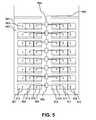
- FIG. 5is an overhead schematic drawing of an embodiment monitoring passenger seats in a commercial aircraft.
- Disclosedis a system and method for monitoring the utilization of seating.
- FIG. 1Ais a front view illustration of a first embodiment of a system 101 .
- Seats 102 , 103 , and 104are passenger seats in a commercial aircraft.
- Sensors 105 , 106 , and 107are each associated with one of seats 102 , 103 , and 104 , respectively.
- sensors 105 , 106 and 107can be built into or attached to an overhead stowage bin.
- Sensors 105 , 106 and 107are configured to communicate with control circuit 108 .
- Control circuit 108is configured to determine the occupancy state of seats 102 , 103 , and 104 using input from their associated sensors 105 , 106 and 107 .
- Control circuit 108communicates with a display (not pictured) that is configured to present occupancy information regarding the occupancy states of seats 102 , 103 , and 104 .
- the displaycan be a centralized display, for instance it may be located in the flight attendant area of the passenger aircraft.
- the displaycan present a manifest report that is formed by cross-checking a passenger manifest with the occupancy states of seats 102 , 103 , and 104 .
- sensors 105 , 106 and 107are echolocation sensors emitting echolocation signals 109 , 110 and 111 .
- Echolocation signals 109 , 110 and 111will strike the nearest surface in a direction of interest and produce a return signal to the sensor that emitted the signal. If a passenger or object is in a particular seat, the echolocation signal from the sensor associated with that seat will produce a return signal in a lesser amount of time than if the seat were empty.
- the occupancy state of a seatcan be determined.
- control circuit 108can receive a measured temperature input and/or a measured altitude input. These inputs can allow control circuit 108 to properly adjust the measurements of sensors 105 , 106 and 107 based on environmental factors and thus adjust the determination of the occupancy states of seats 102 , 103 and 104 . For instance, ultrasonic sensors will be affected by changes in propagation time associated with changing temperature and altitude.
- the disposition of seatsmay be classified into various occupancy states.
- a simple combinationcould consist of “empty” and “occupied.” Other combinations are possible, some depending on the sensors' accuracy. For example, if the sensor detects that there is a surface three inches closer to the sensor than an empty seat, the seat is unlikely to be occupied by a human but may have luggage improperly placed on it.
- a “probable luggage” occupancy statecould indicate to a flight attendant, for example, that that seat should be checked so that any baggage can be properly stored.
- the displaymay take many various forms and make use of various technologies.
- the displaymay utilize a liquid crystal display (LCD) or light emitting diode (LED).
- LCDliquid crystal display
- LEDlight emitting diode
- Various sizesmay also be employed, for instance there may be a small local LCD display next to each of a set of seats and a larger central LED display in a centralized area.
- Communication among elements of embodimentsmay be accomplished by a variety of widely available technologies, including both wired and wireless interfaces such as radio frequencies, Wi-Fi, etc.
- Various sensor typesare suitable for use with the disclosed and other embodiments, including ultrasonic, infrared, LED, photo, and laser sensors.
- any device that can accurately range short distance measurementsis suitable for use as a sensor in keeping with the present disclosure.
- Such sensorsmay vary widely in number and orientation, and may be employed in combination with one another.
- an ultrasonic sensormay be paired with an infrared sensor in order for the system to be better able to distinguish between luggage placed on a seat and a small child.
- the operation of such sensorsis described generally so as not to obscure the subject matter to which the present disclosure is directed, as such sensors are well known and documented.
- FIG. 2is a flowchart diagram of a process embodiment.
- a seat with an associated sensor, and a control circuit in communication with the sensorare provided.
- the sensoris used to measure the distance between the sensor and the seat it is associated with, when the seat is empty. This measurement is used as a baseline against which future determinations as to the occupancy state of the seat can be made.
- the current distance between the sensor and the nearest surface in the sensor's direction of interestis measured.
- the occupancy state of the seatis determined. In an embodiment, the measurement of the distance to the nearest object from step 203 is compared to the baseline measurement of the distance to the seat from step 202 .
- the occupancy state of the seatis not empty. Depending on the measured distance, the occupancy state could indicate that either a passenger or luggage is likely to be present in the seat.
- the control circuitreceives a temperature and altitude input. These inputs can be utilized during the determination of the occupancy state to adjust measurements from the sensors to account for environmental conditions. For example, the signal propagation speed of the sensors may vary due to altitude or temperature.
- the occupancy state of the seatis cross-checked against a passenger manifest.
- occupancy information regarding the occupancy state of the seatis presented on the display.
- step 206If any discrepancies between the passenger manifest and the occupancy state of the seat were identified in step 205 , an alert regarding such a discrepancy is presented in step 206 . For instance, if a seat is supposed to be empty according to the passenger manifest but is, in fact, occupied, a flight crew member can be alerted that the seat should be checked for loose luggage or an errantly seated passenger.
- step 207if the system is still in operation the process returns to step 203 , so that the occupancy state of the seat is continually monitored. If the system is not still in operation, the process is concluded in step 208 .
- the systemcan be easily configured to operate with any number of seat types and configurations.
- FIG. 3is an electrical schematic of an embodiment 301 .
- Control circuit 302contains micro-controller 303 , transmit multiplex 304 and receive multiplex 305 .
- Transmit transducers 306 , 307 , 308are each associated with a respective seat (not pictured), and are connected to transmit multiplex 304 and receive multiplex 305 .
- Microcontroller 303is configured to output to display 309 .
- display 309has first seat indicator 310 , second seat indicator 311 and third seat indicator 312 , that correspond to the seats associated with transducers 306 , 307 and 308 .
- Microcontroller 303can output information to display 309 , particularly information regarding the occupancy state of the seats.
- microcontroller 303also receives a temperature and altitude input.
- Microcontroller 303provides sensor selection, transmit and receive functions as well as occupancy state determinations.
- microcontroller 303selects a first transmit transducer, in this case transmit transducer 306 , through transmit multiplexer 304 and sends a pulse train to transducer 306 using a transmit signal.
- This pulse traincreates a high frequency signal.
- a signalis above the audible range, such as approximately 40 KHz.
- the propagation time of the signalis approximately 1100 ft/second for a 40 KHz signal.
- the pulsetravels through the air and is reflected either by the seat or by an object or person in the seat.
- microcontroller 303can adjust its determination of seat occupancy states to account for differences in sensor operation caused by changes in altitude or temperature.
- display indicator 310indicates that the occupancy state of the seat associated with transducer 306 is unoccupied, or empty. Conversely, display indicator 311 indicates that the occupancy state of the seat associated with transducer 307 is occupied. Display indicator 312 indicates that the seat associated with transducer 308 is occupied but should not be occupied according to a cross-check with a passenger manifest.
- FIG. 4illustrates a display of an embodiment that is centrally located in the flight attendant area of a passenger aircraft.
- Electronic device 401has display 402 .
- display 402Presented on display 402 is information regarding the occupancy states of a set of passenger seats. In the embodiment, empty seats 403 are displayed without shading and occupied seats 404 are displayed with shading.
- Alert 405indicates to the flight crew that the cross check of the passenger manifest with the occupancy states of the passenger seats indicated that a passenger or luggage was present in a seat that should be empty. The flight crew can then go to that seat to either move the errant passenger or stow any stray luggage that may be occupying the seat.
- seats that the manifest shows should be occupied that are emptymay be marked for flight attendants so that additional stand-by passengers may be seated.
- Various methods, symbols, colors, text and numeralsmay optionally be used to relay the occupancy states of the passenger seats.
- FIG. 5is a schematic top view of an embodiment.
- enclosure 501in this case the passenger area of a commercial aircraft, there is a plurality of passenger seats 502 .
- sensors 503with at least one sensor associated with each passenger seat. Each sensor measures the distance between it and the nearest surface in a direction of interest.
- Control circuits 504together receive a distance measurement from each sensor and determine an occupancy state for each of passenger seats 502 .
- Display 505receives from control circuits 504 the occupancy states of each of the passenger seats and displays occupancy information to the user.
- Display 505is centralized in a flight attendant area, so that the flight crew can monitor the boarding process without needing to traverse the aisle.
- control circuit 506has associated with it particular passenger seats 507 , 508 , 509 , 510 , 511 and 512 , each associated with a respective sensor, in this case 511 , 512 , 513 , 514 , 515 and 516 . It should be noted that any number of sensors could be paired with any appropriate number of control circuits, and control circuits may communicate with one another or directly with a display.
Landscapes
- Engineering & Computer Science (AREA)
- Aviation & Aerospace Engineering (AREA)
- Audible And Visible Signals (AREA)
- Air Bags (AREA)
Abstract
Description
Claims (18)
Priority Applications (4)
| Application Number | Priority Date | Filing Date | Title |
|---|---|---|---|
| US14/189,252US9302781B2 (en) | 2014-02-25 | 2014-02-25 | Apparatus and method to monitor the occupancy of seating |
| CA2881140ACA2881140C (en) | 2014-02-25 | 2015-02-04 | Apparatus and method to monitor the occupancy of seating |
| EP15154803.9AEP2910471B1 (en) | 2014-02-25 | 2015-02-12 | Apparatus and method to monitor the occupancy of seating |
| CN201510182001.7ACN104859489A (en) | 2014-02-25 | 2015-02-16 | Apparatus And Method To Monitor The Occupancy Of Seating |
Applications Claiming Priority (1)
| Application Number | Priority Date | Filing Date | Title |
|---|---|---|---|
| US14/189,252US9302781B2 (en) | 2014-02-25 | 2014-02-25 | Apparatus and method to monitor the occupancy of seating |
Publications (2)
| Publication Number | Publication Date |
|---|---|
| US20150239573A1 US20150239573A1 (en) | 2015-08-27 |
| US9302781B2true US9302781B2 (en) | 2016-04-05 |
Family
ID=52596735
Family Applications (1)
| Application Number | Title | Priority Date | Filing Date |
|---|---|---|---|
| US14/189,252ActiveUS9302781B2 (en) | 2014-02-25 | 2014-02-25 | Apparatus and method to monitor the occupancy of seating |
Country Status (4)
| Country | Link |
|---|---|
| US (1) | US9302781B2 (en) |
| EP (1) | EP2910471B1 (en) |
| CN (1) | CN104859489A (en) |
| CA (1) | CA2881140C (en) |
Cited By (5)
| Publication number | Priority date | Publication date | Assignee | Title |
|---|---|---|---|---|
| EP3217340A1 (en) | 2016-03-07 | 2017-09-13 | Astronics Advanced Electronic Systems Corp. | Network system for autonomous data collection |
| DE102018133175A1 (en)* | 2018-12-20 | 2020-06-25 | Airbus Operations Gmbh | Aircraft monitoring system for controlling the safe charging of portable electrical devices |
| WO2022038227A1 (en)* | 2020-08-20 | 2022-02-24 | Diehl Aerospace Gmbh | Cabin for an aircraft, having a monitoring assembly, aircraft having the cabin, monitoring assembly and method for monitoring a cabin of an aircraft |
| US11321641B2 (en)* | 2018-08-21 | 2022-05-03 | International Business Machines Corporation | Managing seat occupancy details of one or more passengers |
| US12091190B2 (en) | 2021-03-25 | 2024-09-17 | Goodrich Lighting Systems GmbH & Co. KG | Aircraft passenger service unit |
Families Citing this family (24)
| Publication number | Priority date | Publication date | Assignee | Title |
|---|---|---|---|---|
| US7978081B2 (en) | 2006-01-09 | 2011-07-12 | Applied Technology Holdings, Inc. | Apparatus, systems, and methods for communicating biometric and biomechanical information |
| US9738396B2 (en) | 2015-09-14 | 2017-08-22 | The Boeing Company | Vehicle occupant sensor system and method |
| US10151661B2 (en) | 2015-09-14 | 2018-12-11 | The Boeing Company | System for monitoring the weight and center of gravity of a vehicle |
| US10055948B2 (en)* | 2015-11-30 | 2018-08-21 | Nike, Inc. | Apparel with ultrasonic position sensing and haptic feedback for activities |
| CN109071025B (en)* | 2016-04-04 | 2022-03-01 | B/E航空公司 | Airplane Passenger Activity Monitoring |
| DE102016209667B4 (en)* | 2016-06-02 | 2025-02-20 | Robert Bosch Gmbh | safety device for a vehicle |
| JP6399414B2 (en) | 2016-10-03 | 2018-10-03 | 本田技研工業株式会社 | Occupant detection system |
| DE102017201965B4 (en)* | 2017-02-08 | 2025-03-06 | Robert Bosch Gmbh | Procedure for detecting seat occupancy |
| EP3592646B1 (en)* | 2017-03-06 | 2021-04-14 | Safran Seats USA LLC | Boarding guidance system |
| WO2018170427A1 (en)* | 2017-03-16 | 2018-09-20 | Systems And Software Enterprises, Llc | Systems and methods for determination of vehicle component status |
| CN107310587A (en)* | 2017-06-22 | 2017-11-03 | 中车唐山机车车辆有限公司 | Seat reminding method and device |
| CN107600440A (en)* | 2017-08-31 | 2018-01-19 | 昆明理工大学 | Airline carriers of passengers safe flight passenger behavior ensuring equipment |
| DE102017217331A1 (en)* | 2017-09-28 | 2019-03-28 | Brose Fahrzeugteile Gmbh & Co. Kommanditgesellschaft, Bamberg | Method for operating an electromotive massage device of a seat |
| IT201700120686A1 (en)* | 2017-10-24 | 2019-04-24 | Italdesign Giugiaro Spa | Space management system available to passengers in a transport service. |
| US10834336B2 (en)* | 2018-01-29 | 2020-11-10 | Ge Aviation Systems Llc | Thermal imaging of aircraft |
| US10479524B2 (en)* | 2018-03-28 | 2019-11-19 | B/E Aerospace, Inc. | Seat sensor array and controller and seat assembly incorporating same |
| GB2575058B (en) | 2018-06-27 | 2022-11-09 | Safran Seats Gb Ltd | An aircraft suite |
| US11136137B2 (en)* | 2018-09-10 | 2021-10-05 | Rockwell Collins, Inc. | Non-intrusive passenger rest cabin monitoring system |
| KR102598956B1 (en)* | 2018-10-15 | 2023-11-07 | 현대자동차주식회사 | Apparatus for detecting a passenger of vehicle, system having the same and method thereof |
| JP2020116974A (en)* | 2019-01-18 | 2020-08-06 | 株式会社小糸製作所 | Projection device for aircraft |
| GB2590406B (en) | 2019-12-16 | 2024-04-03 | Safran Seats Gb Ltd | An aircraft passenger suite |
| US11655032B2 (en)* | 2020-03-19 | 2023-05-23 | B/E Aerospace, Inc. | Systems and methods for efficient boarding of passenger vehicles |
| CN114655267A (en)* | 2022-04-08 | 2022-06-24 | 中车青岛四方机车车辆股份有限公司 | Luggage compartment space detection system and luggage compartment |
| CN116002055B (en)* | 2023-03-27 | 2023-06-27 | 成都旺美达航空科技有限公司 | Authority-based aviation seat adjusting method, device and medium |
Citations (15)
| Publication number | Priority date | Publication date | Assignee | Title |
|---|---|---|---|---|
| US6026340A (en)* | 1998-09-30 | 2000-02-15 | The Robert Bosch Corporation | Automotive occupant sensor system and method of operation by sensor fusion |
| US20030158762A1 (en)* | 2002-01-18 | 2003-08-21 | Jiang Wu | System and method for airplane security / service / maintenance management |
| JP2005082147A (en) | 2003-09-09 | 2005-03-31 | Siemens Ag | Device or method for recognizing an object or person on a seat of a vehicle |
| US20060052933A1 (en)* | 2003-01-14 | 2006-03-09 | Hiroki Ota | Navigation device and approach information display method |
| US20060163430A1 (en)* | 2003-12-29 | 2006-07-27 | Cordina Joseph L | Attendant cabin display system |
| US20070040672A1 (en)* | 2005-08-22 | 2007-02-22 | Andrew Chinigo | Security system for mass transit and mass transportation |
| US20080068220A1 (en)* | 2006-09-08 | 2008-03-20 | Airbus Deutschland Gmbh | Conditional aircraft cabin warning and signalling system for determining the cabin status |
| US20080258890A1 (en)* | 2006-05-22 | 2008-10-23 | Todd Follmer | System and Method for Remotely Deactivating a Vehicle |
| US20100308166A1 (en) | 2007-11-16 | 2010-12-09 | Airbus Operations Gmbh | Seat with a Seat Element, Seat Arrangement and Method for Monitoring a Seat |
| US8089181B2 (en) | 2009-06-30 | 2012-01-03 | Astronics Advanced Electronic Systems Corp. | System and method to measure load type and exclude the human body model |
| US20120221677A1 (en)* | 2011-02-14 | 2012-08-30 | Kt Corporation | Server for providing traffic image to user device, and the user device |
| US20120242492A1 (en)* | 2011-03-25 | 2012-09-27 | Tov 1 LLC | Seat occupancy detection and display system |
| US20130106995A1 (en)* | 2011-10-31 | 2013-05-02 | Samsung Electro-Mechanics Co., Ltd. | Display apparatus for vehicle and method of controlling the same |
| US20130158778A1 (en)* | 2011-12-14 | 2013-06-20 | General Motors Llc | Method of providing information to a vehicle |
| US20130211707A1 (en)* | 2009-12-22 | 2013-08-15 | Cobra Electronics Corporation | Radar detector that interfaces with a mobile communication device |
- 2014
- 2014-02-25USUS14/189,252patent/US9302781B2/enactiveActive
- 2015
- 2015-02-04CACA2881140Apatent/CA2881140C/enactiveActive
- 2015-02-12EPEP15154803.9Apatent/EP2910471B1/enactiveActive
- 2015-02-16CNCN201510182001.7Apatent/CN104859489A/enactivePending
Patent Citations (15)
| Publication number | Priority date | Publication date | Assignee | Title |
|---|---|---|---|---|
| US6026340A (en)* | 1998-09-30 | 2000-02-15 | The Robert Bosch Corporation | Automotive occupant sensor system and method of operation by sensor fusion |
| US20030158762A1 (en)* | 2002-01-18 | 2003-08-21 | Jiang Wu | System and method for airplane security / service / maintenance management |
| US20060052933A1 (en)* | 2003-01-14 | 2006-03-09 | Hiroki Ota | Navigation device and approach information display method |
| JP2005082147A (en) | 2003-09-09 | 2005-03-31 | Siemens Ag | Device or method for recognizing an object or person on a seat of a vehicle |
| US20060163430A1 (en)* | 2003-12-29 | 2006-07-27 | Cordina Joseph L | Attendant cabin display system |
| US20070040672A1 (en)* | 2005-08-22 | 2007-02-22 | Andrew Chinigo | Security system for mass transit and mass transportation |
| US20080258890A1 (en)* | 2006-05-22 | 2008-10-23 | Todd Follmer | System and Method for Remotely Deactivating a Vehicle |
| US20080068220A1 (en)* | 2006-09-08 | 2008-03-20 | Airbus Deutschland Gmbh | Conditional aircraft cabin warning and signalling system for determining the cabin status |
| US20100308166A1 (en) | 2007-11-16 | 2010-12-09 | Airbus Operations Gmbh | Seat with a Seat Element, Seat Arrangement and Method for Monitoring a Seat |
| US8089181B2 (en) | 2009-06-30 | 2012-01-03 | Astronics Advanced Electronic Systems Corp. | System and method to measure load type and exclude the human body model |
| US20130211707A1 (en)* | 2009-12-22 | 2013-08-15 | Cobra Electronics Corporation | Radar detector that interfaces with a mobile communication device |
| US20120221677A1 (en)* | 2011-02-14 | 2012-08-30 | Kt Corporation | Server for providing traffic image to user device, and the user device |
| US20120242492A1 (en)* | 2011-03-25 | 2012-09-27 | Tov 1 LLC | Seat occupancy detection and display system |
| US20130106995A1 (en)* | 2011-10-31 | 2013-05-02 | Samsung Electro-Mechanics Co., Ltd. | Display apparatus for vehicle and method of controlling the same |
| US20130158778A1 (en)* | 2011-12-14 | 2013-06-20 | General Motors Llc | Method of providing information to a vehicle |
Non-Patent Citations (1)
| Title |
|---|
| European Patent Office, European Search Report for EP 15154803.9, dated Jul. 20, 2015. |
Cited By (8)
| Publication number | Priority date | Publication date | Assignee | Title |
|---|---|---|---|---|
| EP3217340A1 (en) | 2016-03-07 | 2017-09-13 | Astronics Advanced Electronic Systems Corp. | Network system for autonomous data collection |
| US9978011B2 (en) | 2016-03-07 | 2018-05-22 | Astronics Advanced Electronic Systems Corp. | Network system for autonomous data collection |
| EP3686825A1 (en) | 2016-03-07 | 2020-07-29 | Astronics Advanced Electronic Systems Corp. | Network system for autonomous data collection |
| US11321641B2 (en)* | 2018-08-21 | 2022-05-03 | International Business Machines Corporation | Managing seat occupancy details of one or more passengers |
| DE102018133175A1 (en)* | 2018-12-20 | 2020-06-25 | Airbus Operations Gmbh | Aircraft monitoring system for controlling the safe charging of portable electrical devices |
| US11136127B2 (en) | 2018-12-20 | 2021-10-05 | Airbus Operations Gmbh | Supervision system for an aircraft for monitoring the safe charging of portable electrical devices |
| WO2022038227A1 (en)* | 2020-08-20 | 2022-02-24 | Diehl Aerospace Gmbh | Cabin for an aircraft, having a monitoring assembly, aircraft having the cabin, monitoring assembly and method for monitoring a cabin of an aircraft |
| US12091190B2 (en) | 2021-03-25 | 2024-09-17 | Goodrich Lighting Systems GmbH & Co. KG | Aircraft passenger service unit |
Also Published As
| Publication number | Publication date |
|---|---|
| US20150239573A1 (en) | 2015-08-27 |
| EP2910471A1 (en) | 2015-08-26 |
| EP2910471B1 (en) | 2020-09-23 |
| CA2881140C (en) | 2022-03-01 |
| CA2881140A1 (en) | 2015-08-25 |
| CN104859489A (en) | 2015-08-26 |
Similar Documents
| Publication | Publication Date | Title |
|---|---|---|
| US9302781B2 (en) | Apparatus and method to monitor the occupancy of seating | |
| US9738396B2 (en) | Vehicle occupant sensor system and method | |
| CN109071025B (en) | Airplane Passenger Activity Monitoring | |
| US8646837B2 (en) | Seat with a seat element, seat arrangement and method for monitoring a seat | |
| CN104864931B (en) | Device and method for monitoring occupied volume in fixed or variable volume | |
| US10752130B2 (en) | Monitoring module for a seat of a passenger aircraft, monitoring device and passenger aircraft | |
| US20170315014A1 (en) | System for monitoring the weight and center of gravity of a vehicle | |
| EP3293117B1 (en) | Aircraft motion assessment systems and methods | |
| CN110386101B (en) | Seat assembly, safety belt safety system and method | |
| US11858640B2 (en) | Aircraft suite | |
| CN104627030A (en) | Carrier safety system and safety detection and processing method applied to same | |
| DE102006030193A1 (en) | System for determining aircraft seat state has seat monitoring device that provides information about state of seat with sensor element for measuring physical data; device determines seat state information from physical data | |
| EP3346278A1 (en) | System and methods to evaluate or improve own ship sensor data in connected vehicles | |
| EP3686107B1 (en) | System and method for detecting items in aircraft stowage areas | |
| WO2016197076A1 (en) | Cell phone texting external monitoring apparatus and method | |
| KR200467855Y1 (en) | System for counting passenger on bus | |
| US20220055752A1 (en) | Health monitoring seating system | |
| CN210101582U (en) | Safety belt detection device | |
| KR102407775B1 (en) | System for confirming kid in school bus | |
| CA3042662A1 (en) | System and method of determining a seat back status of a passenger seat in a vehicle | |
| EP4541715A1 (en) | Systems, methods, and apparatus for monitoring life vests on aircraft | |
| US20160033345A1 (en) | Apparatus for measuring load applied to seat | |
| US10017253B1 (en) | Aircraft cabin pressure assessment systems and methods | |
| KR101582046B1 (en) | The system for preventing a standing passenger in bus |
Legal Events
| Date | Code | Title | Description |
|---|---|---|---|
| AS | Assignment | Owner name:ASTRONICS ADVANCED ELECTRONIC SYSTEMS CORP., WASHI Free format text:ASSIGNMENT OF ASSIGNORS INTEREST;ASSIGNORS:JOUPER, JEFFREY A.;PEABODY, MARK;REEL/FRAME:032294/0732 Effective date:20140224 | |
| STCF | Information on status: patent grant | Free format text:PATENTED CASE | |
| MAFP | Maintenance fee payment | Free format text:PAYMENT OF MAINTENANCE FEE, 4TH YEAR, LARGE ENTITY (ORIGINAL EVENT CODE: M1551); ENTITY STATUS OF PATENT OWNER: LARGE ENTITY Year of fee payment:4 | |
| AS | Assignment | Owner name:HSBC BANK USA, NATIONAL ASSOCIATION, AS AGENT, NEW YORK Free format text:SECURITY INTEREST;ASSIGNORS:ASTRONICS AEROSTAT CORPORATION;ASTRONICS CONNECTIVITY SYSTEMS & CERTIFICATION CORP.;ASTRONICS CORPORATION;AND OTHERS;REEL/FRAME:062445/0342 Effective date:20230119 Owner name:GREAT ROCK CAPITAL MANAGEMENT, LLC, CONNECTICUT Free format text:SECURITY INTEREST;ASSIGNORS:ASTRONICS CUSTOM CONTROL CONCEPTS INC.;ASTRONICS DME LLC;ASTRONICS CORPORATION;AND OTHERS;REEL/FRAME:062444/0836 Effective date:20230119 | |
| MAFP | Maintenance fee payment | Free format text:PAYMENT OF MAINTENANCE FEE, 8TH YEAR, LARGE ENTITY (ORIGINAL EVENT CODE: M1552); ENTITY STATUS OF PATENT OWNER: LARGE ENTITY Year of fee payment:8 | |
| AS | Assignment | Owner name:HSBC BANK USA, N.A., NEW YORK Free format text:SECURITY INTEREST;ASSIGNORS:ASTRONICS CORPORATION;ASTRONICS ADVANCED ELECTRONIC SYSTEMS CORP.;ASTRONICS AEROSAT CORPORATION;AND OTHERS;REEL/FRAME:068283/0900 Effective date:20240711 | |
| AS | Assignment | Owner name:LUMINESCENT SYSTEMS, INC., NEW YORK Free format text:RELEASE BY SECURED PARTY;ASSIGNOR:GREAT ROCK CAPITAL PARTNERS MANAGEMENT, LLC;REEL/FRAME:068311/0938 Effective date:20240711 Owner name:DIAGNOSYS INC., FLORIDA Free format text:RELEASE BY SECURED PARTY;ASSIGNOR:GREAT ROCK CAPITAL PARTNERS MANAGEMENT, LLC;REEL/FRAME:068311/0938 Effective date:20240711 Owner name:ASTRONICS TEST SYSTEMS INC., FLORIDA Free format text:RELEASE BY SECURED PARTY;ASSIGNOR:GREAT ROCK CAPITAL PARTNERS MANAGEMENT, LLC;REEL/FRAME:068311/0938 Effective date:20240711 Owner name:ASTRONICS CORPORATION, NEW YORK Free format text:RELEASE BY SECURED PARTY;ASSIGNOR:GREAT ROCK CAPITAL PARTNERS MANAGEMENT, LLC;REEL/FRAME:068311/0938 Effective date:20240711 Owner name:ASTRONICS ADVANCED ELECTRONIC SYSTEMS CORP., WASHINGTON Free format text:RELEASE BY SECURED PARTY;ASSIGNOR:GREAT ROCK CAPITAL PARTNERS MANAGEMENT, LLC;REEL/FRAME:068311/0938 Effective date:20240711 Owner name:PECO, INC., OREGON Free format text:RELEASE BY SECURED PARTY;ASSIGNOR:GREAT ROCK CAPITAL PARTNERS MANAGEMENT, LLC;REEL/FRAME:068311/0938 Effective date:20240711 Owner name:ASTRONICS CONNECTIVITY SYSTEMS & CERTIFICATION CORP., ILLINOIS Free format text:RELEASE BY SECURED PARTY;ASSIGNOR:GREAT ROCK CAPITAL PARTNERS MANAGEMENT, LLC;REEL/FRAME:068311/0938 Effective date:20240711 Owner name:ASTRONICS AEROSAT CORPORATION, NEW HAMPSHIRE Free format text:RELEASE BY SECURED PARTY;ASSIGNOR:GREAT ROCK CAPITAL PARTNERS MANAGEMENT, LLC;REEL/FRAME:068311/0938 Effective date:20240711 | |
| AS | Assignment | Owner name:DIAGNOSYS INC., MASSACHUSETTS Free format text:RELEASE BY SECURED PARTY;ASSIGNOR:HSBC BANK USA, N.A., AS AGENT;REEL/FRAME:069491/0184 Effective date:20241203 Owner name:PECO, INC., OREGON Free format text:RELEASE BY SECURED PARTY;ASSIGNOR:HSBC BANK USA, N.A., AS AGENT;REEL/FRAME:069491/0184 Effective date:20241203 Owner name:ASTRONICS CONNECTIVITY SYSTEMS & CERTIFICATION CORP., NEW YORK Free format text:RELEASE BY SECURED PARTY;ASSIGNOR:HSBC BANK USA, N.A., AS AGENT;REEL/FRAME:069491/0184 Effective date:20241203 Owner name:LUMINESCENT SYSTEMS, INC., NEW YORK Free format text:RELEASE BY SECURED PARTY;ASSIGNOR:HSBC BANK USA, N.A., AS AGENT;REEL/FRAME:069491/0184 Effective date:20241203 Owner name:ASTRONICS TEST SYSTEMS INC., CALIFORNIA Free format text:RELEASE BY SECURED PARTY;ASSIGNOR:HSBC BANK USA, N.A., AS AGENT;REEL/FRAME:069491/0184 Effective date:20241203 Owner name:ASTRONICS AEROSAT CORPORATION, NEW HAMPSHIRE Free format text:RELEASE BY SECURED PARTY;ASSIGNOR:HSBC BANK USA, N.A., AS AGENT;REEL/FRAME:069491/0184 Effective date:20241203 Owner name:ASTRONICS ADVANCED ELECTRONIC SYSTEMS CORP., WASHINGTON Free format text:RELEASE BY SECURED PARTY;ASSIGNOR:HSBC BANK USA, N.A., AS AGENT;REEL/FRAME:069491/0184 Effective date:20241203 Owner name:ASTRONICS CORPORATION, NEW YORK Free format text:RELEASE BY SECURED PARTY;ASSIGNOR:HSBC BANK USA, N.A., AS AGENT;REEL/FRAME:069491/0184 Effective date:20241203 |