US9302099B2 - System and method for evaluating lead stability of an implantable medical device - Google Patents
System and method for evaluating lead stability of an implantable medical deviceDownload PDFInfo
- Publication number
- US9302099B2 US9302099B2US14/703,760US201514703760AUS9302099B2US 9302099 B2US9302099 B2US 9302099B2US 201514703760 AUS201514703760 AUS 201514703760AUS 9302099 B2US9302099 B2US 9302099B2
- Authority
- US
- United States
- Prior art keywords
- vessel
- lsi
- lead
- processor
- calculate
- Prior art date
- Legal status (The legal status is an assumption and is not a legal conclusion. Google has not performed a legal analysis and makes no representation as to the accuracy of the status listed.)
- Expired - Fee Related
Links
- 238000000034methodMethods0.000titleclaimsabstractdescription41
- 210000003484anatomyAnatomy0.000claimsabstractdescription15
- 238000005259measurementMethods0.000claimsabstractdescription13
- 230000001133accelerationEffects0.000claimsdescription10
- 230000036772blood pressureEffects0.000claimsdescription8
- 230000000747cardiac effectEffects0.000description16
- 239000000523sampleSubstances0.000description15
- 230000002861ventricularEffects0.000description14
- 230000015654memoryEffects0.000description13
- 230000001746atrial effectEffects0.000description12
- 238000003384imaging methodMethods0.000description10
- 210000003462veinAnatomy0.000description7
- 238000012545processingMethods0.000description6
- 238000002560therapeutic procedureMethods0.000description6
- 210000003748coronary sinusAnatomy0.000description5
- 230000004044responseEffects0.000description5
- 230000000638stimulationEffects0.000description5
- 208000036829Device dislocationDiseases0.000description4
- 238000004891communicationMethods0.000description4
- 239000007943implantSubstances0.000description4
- 210000002620vena cava superiorAnatomy0.000description4
- 238000004590computer programMethods0.000description3
- 230000006870functionEffects0.000description3
- 238000013507mappingMethods0.000description3
- 239000000463materialSubstances0.000description3
- 238000004458analytical methodMethods0.000description2
- 238000009125cardiac resynchronization therapyMethods0.000description2
- 238000005094computer simulationMethods0.000description2
- 238000010586diagramMethods0.000description2
- 230000002526effect on cardiovascular systemEffects0.000description2
- 210000005240left ventricleAnatomy0.000description2
- 238000004137mechanical activationMethods0.000description2
- 230000003287optical effectEffects0.000description2
- 230000008569processEffects0.000description2
- 230000005855radiationEffects0.000description2
- 230000000241respiratory effectEffects0.000description2
- 210000005241right ventricleAnatomy0.000description2
- 238000002633shock therapyMethods0.000description2
- 238000012800visualizationMethods0.000description2
- 208000033986Device capturing issueDiseases0.000description1
- 208000026930Twiddler syndromeDiseases0.000description1
- 238000002679ablationMethods0.000description1
- 230000001154acute effectEffects0.000description1
- 230000006399behaviorEffects0.000description1
- 230000017531blood circulationEffects0.000description1
- 238000009530blood pressure measurementMethods0.000description1
- 210000004556brainAnatomy0.000description1
- 210000005242cardiac chamberAnatomy0.000description1
- 238000012512characterization methodMethods0.000description1
- 238000000576coating methodMethods0.000description1
- 239000003086colorantSubstances0.000description1
- 238000013170computed tomography imagingMethods0.000description1
- 230000005672electromagnetic fieldEffects0.000description1
- 230000007831electrophysiologyEffects0.000description1
- 238000002001electrophysiologyMethods0.000description1
- 238000002594fluoroscopyMethods0.000description1
- 210000005246left atriumAnatomy0.000description1
- 238000002595magnetic resonance imagingMethods0.000description1
- 238000012986modificationMethods0.000description1
- 230000004048modificationEffects0.000description1
- 238000002600positron emission tomographyMethods0.000description1
- 210000005247right atrial appendageAnatomy0.000description1
- 210000005245right atriumAnatomy0.000description1
- 238000002604ultrasonographyMethods0.000description1
- 210000005166vasculatureAnatomy0.000description1
- 230000000007visual effectEffects0.000description1
- 239000011800void materialSubstances0.000description1
Images


Classifications
- A—HUMAN NECESSITIES
- A61—MEDICAL OR VETERINARY SCIENCE; HYGIENE
- A61N—ELECTROTHERAPY; MAGNETOTHERAPY; RADIATION THERAPY; ULTRASOUND THERAPY
- A61N1/00—Electrotherapy; Circuits therefor
- A61N1/02—Details
- A61N1/04—Electrodes
- A61N1/05—Electrodes for implantation or insertion into the body, e.g. heart electrode
- A61N1/056—Transvascular endocardial electrode systems
- A61N1/057—Anchoring means; Means for fixing the head inside the heart
- A—HUMAN NECESSITIES
- A61—MEDICAL OR VETERINARY SCIENCE; HYGIENE
- A61N—ELECTROTHERAPY; MAGNETOTHERAPY; RADIATION THERAPY; ULTRASOUND THERAPY
- A61N1/00—Electrotherapy; Circuits therefor
- A61N1/02—Details
- A61N1/04—Electrodes
- A61N1/05—Electrodes for implantation or insertion into the body, e.g. heart electrode
- A61N1/056—Transvascular endocardial electrode systems
- A61N1/057—Anchoring means; Means for fixing the head inside the heart
- A61N2001/0578—Anchoring means; Means for fixing the head inside the heart having means for removal or extraction
Definitions
- Embodiments of the present disclosuregenerally relate to systems and methods for evaluating lead stability of an implantable medical device.
- Lead dislodgementis a common complication of cardiac resynchronization therapy (CRT) implants that may lead to increased capture thresholds, loss of capture, reduced biventricular pacing, and reduced response.
- CRTcardiac resynchronization therapy
- Possible causes of lead dislodgementinclude twiddler syndrome, device migration especially in obese patients, and excessive movement due to cardiac and/or respiratory motion, especially during hyperapnea.
- the St. Jude Medical MediGuideTM (MDG) cardiovascular navigation systemis a 3-D electromagnetic navigation system that provides real-time position and orientation of MDG sensors embedded in electrophysiological tools.
- the MDG systemmay be integrated with a fluoroscopic imaging system and tracks the sensors continuously within the imaging volume of the fluoroscopic system, on both live fluoroscopy and pre-recorded backgrounds.
- Embodiments of the present disclosureprovide systems and methods for predicting lead stability in candidate vessels at the time of implant in order to guide a physician to an optimal implant site and to recommend which lead to use.
- Certain embodiments of the present disclosureprovide a method that may include providing feedback regarding lead stability for a candidate target vessel, and providing guidance on a type of lead to be used.
- Certain embodiments of the present disclosureprovide a method that may include utilizing a surgical navigation system and information regarding patient anatomy to predict lead stability within the patient anatomy.
- Certain embodiments of the present disclosureprovide a method that may include providing patient-specific force measurements for one or more vessels of a patient.
- Certain embodiments of the present disclosureprovide a system for determining a lead placement site within patient anatomy.
- the systemmay include at least one processor configured to calculate a lead stability index (LSI) relating to a lead placement site for one or more candidate vessels, and a display operatively coupled to the at least one processor.
- the displayis configured to show data related to the lead placement site.
- the processor(s)may be configured to display the data related to the lead placement site on the display as color-coded data.
- the processor(s)may be configured to calculate the LSI through the following equation:
- L ⁇ ⁇ S ⁇ ⁇ I⁇ ⁇ T ⁇ L a ⁇ ⁇
- Tis a measure of vessel tortuosity
- Lis a vessel length
- ais a largest second derivative of the three-dimensional (3-D) motion experienced by the vessel
- ⁇is an ostial take-off angle
- ⁇is a constant.
- the processor(s)may be configured to calculate the LSI through the following equation:
- L ⁇ ⁇ S ⁇ ⁇ I⁇ ⁇ T ⁇ L a ⁇ ⁇ ⁇ s ⁇ ⁇ ⁇ P
- Tis a measure of vessel tortuosity
- Lis a vessel length
- ais a largest second derivative of the three-dimensional (3-D) motion experienced by the vessel
- ⁇is an ostial take-off angle
- ⁇is a constant
- sis a maximum lead body mechanical stress
- APis a blood pressure differential from a tip to an ostium of the vessel.
- the processor(s)may be configured to calculate the LSI of the one or more candidate vessels based on motion and anatomical measurements in each of the one more candidate vessels.
- the processor(s)may be configured to calculate the LSI, at least in part, by accounting for one or more of (a) acceleration experienced by the one or more candidate vessels, (b) vessel tortuosity, (c) vessel length, and/or (d) ostial angle.
- Certain embodiments of the present disclosureprovide a method for determining a lead placement site within patient anatomy.
- the methodmay include calculating a lead stability index (LSI) relating to lead placement site for one or more candidate vessels, and displaying data related to the lead placement site.
- LSIlead stability index
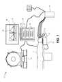
- FIG. 1illustrates a schematic diagram of a system 10 , according to an embodiment of the present disclosure.
- FIG. 2illustrates a simplified view of an exemplary implantable medical device (IMD) in electrical communication with at least three leads implanted into a patient's heart, according to an embodiment of the present disclosure.
- IMDimplantable medical device
- FIG. 3illustrates a display showing a vessel, according to an embodiment of the present disclosure.
- Embodiments hereinmay be implemented with, and/or utilize aspects of, the methods and system described in the following applications:
- FIG. 1illustrates a schematic diagram of a system 10 , according to an embodiment of the present disclosure.
- the system 10may include an imaging sub-system 12 configured to acquire images of a patient 14 , a positioning sub-system 16 , and a surgical navigation sub-system 18 .
- the imaging sub-system 12is used to acquire one or more images of the patient 14 .
- the imaging sub-system 12is configured to acquire one or more images of a heart of a patient.
- the positioning sub-system 16may be used to position probes, sensors, leads, and the like into the patient 14 .
- the surgical navigation sub-system 18may be used in conjunction with the acquired images to allow a surgeon to visualize placement of the probes of the positioning sub-system 16 into the patient 14 .
- the system 10may not include the positioning sub-system 16 .
- the systemmay be used with respect to imaging and navigation with respect to other anatomical structure of the patient other than the heart.
- the imaging sub-system 12may include one or more of an X-ray, fluoroscope, CT, MRI, Positron Emission Tomography (PET), ultrasound, or other such imaging systems.
- the imaging sub-system 12may include MRI and CT imaging systems.
- the imaging sub-system 12may include a radiation source or generator and a radiation sensor or detector.
- the surgical navigation sub-system 18may include a main housing 32 , such as a computer workstation, operatively connected to a display 34 that is configured to display images 36 thereon.
- the display 34may be or include a monitor, screen, television, or the like, for example.
- the surgical navigation sub-system 18may be used to electromagnetically track movement of probes of the positioning sub-system 16 before and during a procedure.
- the surgical navigation sub-system 18may be used to automate surgical planning and lead or probe placement, while displaying a current position of the lead or probe within the patient anatomy.
- the main housing 32may contain a registration module 35 , a tracking module 37 , and a display module 39 .
- the registration module 35may be configured to register reference members, such as fiducials, coils, and/or the like, of a frame, probe, or the like, with one or more reference markers, points, or the like of images of patient anatomy.
- the tracking module 37is configured to track movement of a probe, for example, with respect to an area or volume, such as within the heart.
- the display module 39is configured to display a representation of the probe, for example, on one or more acquired images on the display, based on the movement of the probe as determined by the tracking module 37 .
- Each of the modules 35 , 37 , and 39may include any processor-based or microprocessor-based system including systems using microcontrollers, reduced instruction set computers (RISC), application specific integrated circuits (ASICs), logic circuits, and any other circuit or processor capable of executing the functions described herein.
- each of the modules 35 , 37 , and 39may be or include at least one processor and at least one memory.
- the aboveare exemplary only, and are thus not intended to limit in any way the definition and/or meaning of the term “computer” or “module.”
- the surgical navigation sub-system 18may also include a tracking assembly 33 in the vicinity of the patient 14 .
- the tracking assembly 33may include a housing situated on or underneath a platform on which the patient 14 rests.
- the tracking assembly 33may include one or more transmitters 31 configured to radiate a field, such as an electromagnetic field, within the vicinity of the patient 14 .
- the field radiated by the transmitters 31may be detected by a position detector of a probe, for example, as described below.
- the surgical navigation sub-system 18may be used with various anatomical structures.
- the surgical navigation sub-system 18may be used to track movement of devices, instruments, probes, and the like within the heart of the patient.
- the surgical navigation sub-systemmay be further described with respect to U.S. Pat. No. 7,811,294, entitled “Automatic Guidewire Maneuvering System and Method,” which is hereby incorporated by reference in its entirety.
- the surgical navigation sub-systemmay be used to visualize movement of the probe with respect to one or more images of the heart.
- the surgical navigation sub-systemmay be used to automatically move a probe according to a surgical plan.
- the surgical navigation sub-systemmay be used to simply superimpose an image of the probe with respect to the image(s) of the heart, brain, or the like in order to track movement of the surgical probe with respect thereto.
- FIG. 2illustrates an IMD 110 in electrical communication with a patient's heart 112 by way of three leads 120 , 124 and 130 suitable for delivering multi-chamber stimulation and/or shock therapy.
- the IMD 110is coupled to an implantable right atrial (RA) lead 120 including at least one atrial tip electrode 122 that typically is implanted in the patient's right atrial appendage.
- the right atrial lead 120may also include an atrial ring electrode 123 to allow bipolar stimulation or sensing in combination with the atrial tip electrode 122 .
- the IMD 110is coupled to a lead 124 designed for placement in the “coronary sinus region” via the coronary sinus ostium in order to place a distal electrode adjacent to the left ventricle and additional electrode(s) adjacent to the left atrium.
- the phrase “coronary sinus region”refers to the venous vasculature of the left ventricle, including any portion of the coronary sinus, great cardiac vein, left marginal vein, left posterior ventricular vein, middle cardiac vein, and/or small cardiac vein or any other cardiac vein accessible by the coronary sinus.
- the lead 124is designed to: receive atrial and/or ventricular cardiac signals; deliver left ventricular pacing therapy using at least one left ventricular tip electrode 126 for unipolar configurations or in combination with left ventricular ring electrode 125 for bipolar configurations; and/or deliver left atrial pacing therapy using at least one left atrial ring electrode 127 as well as shocking therapy using at least one left atrial coil electrode 128 .
- the IMD 110is also shown in electrical communication with the patient's heart 112 by way of an implantable right ventricular (RV) lead 130 including, in the embodiment, a right ventricular (RV) tip electrode 132 , a right ventricular ring electrode 134 , a right ventricular coil electrode 136 , a superior vena cava (SVC) coil electrode 138 , and so on.
- RVright ventricular
- SVCsuperior vena cava
- the right ventricular lead 130is inserted transvenously into the heart 112 so as to place the right ventricular tip electrode 132 in the right ventricular apex such that the RV coil electrode 136 is positioned in the right ventricle and the SVC coil electrode 138 will be positioned in the right atrium and/or superior vena cava.
- the right ventricular lead 130is capable of receiving cardiac signals, and delivering stimulation in the form of pacing and shock therapy to the right ventricle.
- the IMDmay be one of various types of implantable devices, such as, for example, an implantable pacemaker, implantable cardioverter-defibrillator (“ICD”), neurostimulator, electrophysiology (“EP”) mapping and radio frequency (“RF”) ablation system, or the like.
- ICDimplantable cardioverter-defibrillator
- EPelectrophysiology
- RFradio frequency
- the IMDmay be configured to provide leadless therapy.
- the surgical navigation sub-system and/or at least one processormay be used to guide a lead to an implant site, such as within a heart of a patient.
- a lead stability index(LSI) may be calculated for each candidate vessel that may guide the physician to the site of LV lead placement, as well as provide guidance on the type of lead to be implanted.
- the informationmay be conveyed to the physician in a visual manner, such as through color-coding of the geometry, and in a quantitative manner by providing the LSI score.
- LSI parametersmay be measured by placing an MDG-enabled tool along the length of the candidate target branches. LSI may be calculated as
- Tis a measure of vessel tortuosity
- Lis the vessel length
- ais the largest second derivative of the three-dimensional (3-D) motion experienced by the vessel
- ⁇is the ostial take-off angle
- ⁇is a constant.
- the LSI measurementsmay be refined through processes that include the addition of maximum lead body mechanical stress (s) and the blood pressure differential from the tip to the ostium of the vessel ( ⁇ P). If these measurements are used, then LSI may be calculated as follows:
- FIG. 3illustrates a display 200 showing a vessel 202 , according to an embodiment of the present disclosure.
- the display 200may be display 34 , or a portion thereof.
- embodiments of the present disclosuremay show the vessel 202 having areas identified with different indicia.
- various areas of the vessel 202may be color-coded to indicate desirability (or lack thereof) of lead placement.
- the areas 204may include specific indicia, such as different colors, that may indicate that they are less than desirable for lead placement.
- the areas 204may be areas of higher stress, strain, or the like.
- the surgical navigation systemcalculates a lead stability index (LSI) of candidate vessels based on motion and anatomical measurements in each vessel.
- LSI indexthe higher the likelihood of lead dislodgement.
- an optimal site of LV lead placementmay be recommended to the physician.
- the following parametersmay be measured or taken into account:
- the second derivative of the 3D motion signals (x,y,z)may then be calculated to obtain 3 acceleration signals.
- the parameter amay be the maximum acceleration among the three signals experienced by the vessel in any dimension at any point in the recording.
- Vessel tortuositythe trajectory of the MDG-enabled tool within the vessel may be evaluated to determine the degree of tortuosity. The more tortuous a vessel is with additional curves and bends, the more contact between the lead body and the vessel wall, the higher the frictional forces between their interfaces, and the more stable the lead. For a given bend below a certain pre-defined angle threshold (such as 60 degrees), a value of 1 may be added to the tortuosity value T.
- Vessel length (L)the trajectory of the tool may be analyzed to determine the length of the vessel. The longer the vessel, the further the lead may be wedged into the vessel, and the higher the stability index.
- Ostial angle ( ⁇ )a more acute take-off angle (in radians) at the target branch ostium increases lead stability.
- the LSImay be defined as (K is a scaling factor to be determined empirically)
- LSImay be further refined through lead body mechanical stress (s): if a point-by-point measurement of motion along the length of the vessel is possible, the internal strain of the lead may be calculated. With known lead geometry, mass, and material properties, the measured strains may be translated into mechanical stress using techniques such as assumed normalized values for all patients, or patient-specific computational modeling that takes all applied forces into account. If there are areas of high stress larger than a pre-defined threshold within the calculated stress profile of the lead, the LSI may be reduced as the lead body would move in response to the exerted stress. The parameter s is defined as the maximum stress experienced in any dimension. With this measurement, different lead geometries/designs may be considered and an optimal lead type may be recommended to the physician.
- lead body mechanical stresss
- LSImay also be refined through blood pressure differential (AP): two blood pressure measurements may be taken, one at the distal end of the vessel and one at the proximal end of the vessel close to the target vein ostium. The higher the blood pressure differential within the vessel, the more blood flow, and therefore more forces are applied to the lead body. Higher AP may correspond to lower LSI.
- APblood pressure differential
- LSImay be calculated as follows:
- L ⁇ ⁇ S ⁇ ⁇ I⁇ ⁇ T ⁇ L a ⁇ ⁇ ⁇ s ⁇ ⁇ ⁇ ⁇ P
- the LSImay be converted to a color that is projected onto the anatomy.
- the computations and analyses described in the present applicationmay be performed by one or more processors, which may include or be communicatively coupled to one or more memories.
- Various embodiments described hereinprovide a tangible and non-transitory (for example, not an electric signal) machine-readable medium or media having instructions recorded thereon for one or more processors or computers to operate a system to perform one or more embodiments of methods described herein.
- the medium or mediamay be any type of CD-ROM, DVD, floppy disk, hard disk, optical disk, flash RAM drive, or other type of computer-readable medium or a combination thereof.
- the various embodiments and/or componentsalso may be implemented as part of one or more computers or processors.
- the computer or processormay include a computing device, an input device, a display unit and an interface, for example, for accessing the Internet.
- the computer or processormay include a microprocessor.
- the microprocessormay be connected to a communication bus.
- the computer or processormay also include a memory.
- the memorymay include Random Access Memory (RAM) and Read Only Memory (ROM).
- the computer or processormay also include a storage device, which may be a hard disk drive or a removable storage drive such as a floppy disk drive, optical disk drive, and the like.
- the storage devicemay also be other similar means for loading computer programs or other instructions into the computer or processor.
- the term “computer” or “module”may include any processor-based or microprocessor-based system including systems using microcontrollers, reduced instruction set computers (RISC), application specific integrated circuits (ASICs), logic circuits, and any other circuit or processor capable of executing the functions described herein.
- RISCreduced instruction set computers
- ASICsapplication specific integrated circuits
- the above examplesare exemplary only, and are thus not intended to limit in any way the definition and/or meaning of the term “computer” or “module.”
- the computer or processorexecutes a set of instructions that are stored in one or more storage elements, in order to process input data.
- the storage elementsmay also store data or other information as desired or needed.
- the storage elementmay be in the form of an information source or a physical memory element within a processing machine.
- the set of instructionsmay include various commands that instruct the computer or processor as a processing machine to perform specific operations such as the methods and processes of the various embodiments of the subject matter described herein.
- the set of instructionsmay be in the form of a software program.
- the softwaremay be in various forms such as system software or application software. Further, the software may be in the form of a collection of separate programs or modules, a program module within a larger program or a portion of a program module.
- the softwarealso may include modular programming in the form of object-oriented programming.
- the processing of input data by the processing machinemay be in response to user commands, or in response to results of previous processing, or in response to a request made by another processing machine.
- the terms “software” and “firmware”may be interchangeable, and include any computer program stored in memory for execution by a computer, including RAM memory, ROM memory, EEPROM memory, and non-volatile RAM (NVRAM) memory.
- RAM memoryrandom access memory
- ROM memoryread-only memory
- EEPROM memoryelectrically erasable programmable read-only memory
- NVRAMnon-volatile RAM
- the above memory typesare exemplary only, and are thus not limiting as to the types of memory usable for storage of a computer program.
- orientationsmay be inverted, rotated, or otherwise changed, such that an upper portion is a lower portion, and vice versa, horizontal becomes vertical, and the like.
Landscapes
- Health & Medical Sciences (AREA)
- Heart & Thoracic Surgery (AREA)
- Cardiology (AREA)
- Nuclear Medicine, Radiotherapy & Molecular Imaging (AREA)
- Engineering & Computer Science (AREA)
- Biomedical Technology (AREA)
- Vascular Medicine (AREA)
- Radiology & Medical Imaging (AREA)
- Life Sciences & Earth Sciences (AREA)
- Animal Behavior & Ethology (AREA)
- General Health & Medical Sciences (AREA)
- Public Health (AREA)
- Veterinary Medicine (AREA)
- Apparatus For Radiation Diagnosis (AREA)
Abstract
Description
where T is a measure of vessel tortuosity, L is a vessel length, a is a largest second derivative of the three-dimensional (3-D) motion experienced by the vessel, α is an ostial take-off angle, and κ is a constant.
where T is a measure of vessel tortuosity, L is a vessel length, a is a largest second derivative of the three-dimensional (3-D) motion experienced by the vessel, α is an ostial take-off angle, κ is a constant, s is a maximum lead body mechanical stress, and AP is a blood pressure differential from a tip to an ostium of the vessel.
- U.S. patent application Ser. No. 14/328,523, filed Jul. 10, 2014, titled “METHOD AND SYSTEM TO ASSESS MECHANICAL DYSSYNCHRONY BASED ON MOTION DATA COLLECTED BY A NAVIGATION SYSTEM”now U.S. Patent Pub. No. 2015/0133802,
- U.S. patent application Ser. No. 14/328,513, filed Jul. 10, 2014, titled “METHOD AND SYSTEM TO MEASURE CARDIAC MOTION USING A CARDIOVASCULAR NAVIGATION SYSTEM”now U.S. Patent Pub. No. 2015/0141858,
- U.S. patent application Ser. No. 14/478,707, filed Sept. 5, 2014, titled “METHOD AND SYSTEM TO IDENTIFY MOTION DATA ASSOCIATED WITH CONSISTENT ELECTRICAL AND MECHANICAL BEHAVIOR FOR A REGION OF INTEREST”now U.S. Patent Pub. No. 2015/0141765,
- U.S patent application 61/988,779, filed May 5, 2014, titled “METHODS AND SYSTEMS TO CALCULATE TIME OF MECHANICAL ACTIVATION USING CHARACTERICATION MOTION DATA AREA STRAINS”,
- U.S. patent application Ser. No. 14/270,181, filed May 5, 2014, titled “METHOD AND SYSTEM TO CHARACTERIZE MOTION DATA BASED ON NEIGHBORING MAP POINTS”now U.S. Patent Pub. No. 2015/0313511,
- U.S. patent application Ser. No. 14/270,186, filed May 5,2014titled “METHOD AND SYSYTEM FOR CACLULATING STRAIN FROM CHARACTERIZATION DATA OF A CARDIAC CHAMBER”, now U.S. Patent Pub. No. 2015/0313480,
- U.S. patent application Ser. No. 14/270,176, filed May 5, 2014, titled “METHOD AND SYSTEM FOR DISPLAYING A THREE DIMENSIONAL VISUALIZATION OF CARDIAC MOTION”, now U.S. Patent Pub. No. 2015/0313510,
- U.S. patent application 61/988,735, filed May 5, 2014, titled “METHOD AND SYSTEM TO DETERMINE CARDIAC CYCLE LENGTH IN CONNECTION WITH CARDIAC MAPPING”,
- U.S. pat application 61/988,763, filed May 5, 2014, titled “METHOD AND SYSTEM TO EQUALIZING CARDIAC CYCLE LENGTH BETWEEN MAP POINTS”,
- U.S. pat application 61/988,767, filed May 5, 2014, titled “METHOD AND SYSTEM TO SUBDIVIDE A MAPPING AREA FOR MECHANICAL ACTIVATION ANALYSIS”, and
- U.S. pat application 61/988,771, filed May 5, 2014, titled “CARDIAC RESYNCHRONIZATION SYSTEM AND METHOD”.
In order to provide feedback on the stability likelihood of the lead in a particular vessel, a color-based visualization of the venogram or of a 3-D reconstruction of the vessel tree may be used. In this case, the LSI may be converted to a color that is projected onto the anatomy.
Claims (20)
Priority Applications (1)
| Application Number | Priority Date | Filing Date | Title |
|---|---|---|---|
| US14/703,760US9302099B2 (en) | 2014-05-05 | 2015-05-04 | System and method for evaluating lead stability of an implantable medical device |
Applications Claiming Priority (2)
| Application Number | Priority Date | Filing Date | Title |
|---|---|---|---|
| US201461988774P | 2014-05-05 | 2014-05-05 | |
| US14/703,760US9302099B2 (en) | 2014-05-05 | 2015-05-04 | System and method for evaluating lead stability of an implantable medical device |
Publications (2)
| Publication Number | Publication Date |
|---|---|
| US20150314121A1 US20150314121A1 (en) | 2015-11-05 |
| US9302099B2true US9302099B2 (en) | 2016-04-05 |
Family
ID=54354430
Family Applications (1)
| Application Number | Title | Priority Date | Filing Date |
|---|---|---|---|
| US14/703,760Expired - Fee RelatedUS9302099B2 (en) | 2014-05-05 | 2015-05-04 | System and method for evaluating lead stability of an implantable medical device |
Country Status (1)
| Country | Link |
|---|---|
| US (1) | US9302099B2 (en) |
Citations (43)
| Publication number | Priority date | Publication date | Assignee | Title |
|---|---|---|---|---|
| US5391199A (en) | 1993-07-20 | 1995-02-21 | Biosense, Inc. | Apparatus and method for treating cardiac arrhythmias |
| WO1997024981A2 (en) | 1996-01-08 | 1997-07-17 | Biosense Inc. | Cardiac electro-mechanics |
| EP1070480A2 (en) | 1999-07-22 | 2001-01-24 | Biosense, Inc. | Vector mapping of three-dimensionally reconstructed intrabody organs and method of display |
| US6233476B1 (en) | 1999-05-18 | 2001-05-15 | Mediguide Ltd. | Medical positioning system |
| US20030093067A1 (en) | 2001-11-09 | 2003-05-15 | Scimed Life Systems, Inc. | Systems and methods for guiding catheters using registered images |
| US6609027B2 (en) | 2001-02-23 | 2003-08-19 | Pacesetter, Inc. | His Bundle sensing device and associated method |
| US6633686B1 (en) | 1998-11-05 | 2003-10-14 | Washington University | Method and apparatus for image registration using large deformation diffeomorphisms on a sphere |
| US20030233039A1 (en) | 2002-06-12 | 2003-12-18 | Lingxiong Shao | Physiological model based non-rigid image registration |
| US6728562B1 (en) | 1992-09-23 | 2004-04-27 | Endocardial Solutions, Inc. | Method for creating a virtual electrogram |
| US6751492B2 (en) | 1993-07-20 | 2004-06-15 | Biosense, Inc. | System for mapping a heart using catheters having ultrasonic position sensors |
| EP1508300A1 (en) | 2003-08-20 | 2005-02-23 | Biosense Webster, Inc. | Transient event mapping in the heart |
| US20050154282A1 (en) | 2003-12-31 | 2005-07-14 | Wenguang Li | System and method for registering an image with a representation of a probe |
| US6978168B2 (en) | 1992-09-23 | 2005-12-20 | Endocardial Solutions, Inc. | Software for mapping potential distribution of a heart chamber |
| US20060245536A1 (en) | 2005-04-19 | 2006-11-02 | Dieter Boing | System for generating, evaluating and distributing computer-tomographical 4D representations of the heart of a patient |
| US7197354B2 (en) | 2004-06-21 | 2007-03-27 | Mediguide Ltd. | System for determining the position and orientation of a catheter |
| US20070073179A1 (en) | 2005-09-15 | 2007-03-29 | St. Jude Medical, Atrial Fibrillation Division, Inc. | System and Method for Three Dimensional Mapping of Electrophysiology Information |
| US20070100332A1 (en) | 2005-10-27 | 2007-05-03 | St. Jude Medical, Atrial Fibrillation Division, Inc. | Systems and methods for electrode contact assessment |
| US20070106146A1 (en) | 2005-10-28 | 2007-05-10 | Altmann Andres C | Synchronization of ultrasound imaging data with electrical mapping |
| US20070181139A1 (en) | 2004-05-28 | 2007-08-09 | Hauck John A | Robotic surgical system with contact sensing feature |
| US7263397B2 (en) | 1998-06-30 | 2007-08-28 | St. Jude Medical, Atrial Fibrillation Division, Inc. | Method and apparatus for catheter navigation and location and mapping in the heart |
| US7276064B2 (en) | 2004-05-27 | 2007-10-02 | St. Jude Medical, Atrial Fibrillation Division, Inc. | Side-port sheath for catheter placement and translation |
| US20070244479A1 (en) | 1992-09-23 | 2007-10-18 | St. Jude Medical, Atrial Fibrillation Division, Inc. | Electrophysiology Therapy Catheter |
| US20070270705A1 (en) | 2006-05-17 | 2007-11-22 | Starks Daniel R | System and method for complex geometry modeling of anatomy using multiple surface models |
| US20080009758A1 (en) | 2006-05-17 | 2008-01-10 | Voth Eric J | System and method for mapping electrophysiology information onto complex geometry |
| US7338486B2 (en) | 1996-10-22 | 2008-03-04 | St. Jude Medical, Atrial Fibrillation Division, Inc. | Methods and devices for ablation |
| US20080091193A1 (en) | 2005-05-16 | 2008-04-17 | James Kauphusman | Irrigated ablation catheter having magnetic tip for magnetic field control and guidance |
| US7386339B2 (en) | 1999-05-18 | 2008-06-10 | Mediguide Ltd. | Medical imaging and navigation system |
| US7505809B2 (en) | 2003-01-13 | 2009-03-17 | Mediguide Ltd. | Method and system for registering a first image with a second image relative to the body of a patient |
| US20090163904A1 (en) | 2005-12-06 | 2009-06-25 | St. Jude Medical, Atrial Fibrillation Division, Inc. | System and Method for Assessing Coupling Between an Electrode and Tissue |
| US20090171345A1 (en) | 2007-12-28 | 2009-07-02 | Miller Stephan P | System and method for measurement of an impedance using a catheter such as an ablation catheter |
| US20100168550A1 (en) | 2008-12-31 | 2010-07-01 | Byrd Israel A | Multiple shell construction to emulate chamber contraction with a mapping system |
| US20100268059A1 (en) | 2009-04-07 | 2010-10-21 | Pacesetter, Inc. | Therapy optimization via multi-dimensional mapping |
| US7881769B2 (en) | 2002-11-18 | 2011-02-01 | Mediguide Ltd. | Method and system for mounting an MPS sensor on a catheter |
| US8016764B1 (en) | 2006-11-08 | 2011-09-13 | Pacesetter, Inc. | Systems and methods for evaluating ventricular dyssynchrony using atrial and ventricular pressure measurements obtained by an implantable medical device |
| US20110243401A1 (en) | 2010-03-31 | 2011-10-06 | Zabair Adeala T | System and method for image sequence processing |
| WO2012090148A1 (en) | 2010-12-30 | 2012-07-05 | Mediguide Ltd | System and method for registration of fluoroscopic images in a coordinate system of a medical system |
| US20120184863A1 (en) | 2011-01-13 | 2012-07-19 | Rhythmia Medical, Inc. | Electroanatomical mapping |
| US20130222415A1 (en) | 2012-02-28 | 2013-08-29 | Stefan Vilsmeier | Calculation of a medical image using templates |
| EP2757528A1 (en) | 2013-01-22 | 2014-07-23 | Pie Medical Imaging BV | Method and apparatus for tracking objects in a target area of a moving organ |
| US20150045867A1 (en)* | 2012-03-15 | 2015-02-12 | Subramaniam Chitoor Krishnan | Mechanism, system, method for in vivo lead fixation |
| US20150133802A1 (en) | 2013-11-19 | 2015-05-14 | Pacesetter, Inc. | Method and system to assess mechanical dyssynchrony based on motion data collected by a navigation system |
| US20150141858A1 (en) | 2013-11-19 | 2015-05-21 | Pacesetter, Inc. | Method and system to measure cardiac motion using a cardiovascular navigation system |
| US20150141765A1 (en) | 2013-11-19 | 2015-05-21 | Pacesetter, Inc. | Method and system to identify motion data associated with consistent electrical and mechanical behavior for a region of interest |
- 2015
- 2015-05-04USUS14/703,760patent/US9302099B2/ennot_activeExpired - Fee Related
Patent Citations (46)
| Publication number | Priority date | Publication date | Assignee | Title |
|---|---|---|---|---|
| US6728562B1 (en) | 1992-09-23 | 2004-04-27 | Endocardial Solutions, Inc. | Method for creating a virtual electrogram |
| US6978168B2 (en) | 1992-09-23 | 2005-12-20 | Endocardial Solutions, Inc. | Software for mapping potential distribution of a heart chamber |
| US20070244479A1 (en) | 1992-09-23 | 2007-10-18 | St. Jude Medical, Atrial Fibrillation Division, Inc. | Electrophysiology Therapy Catheter |
| US5391199A (en) | 1993-07-20 | 1995-02-21 | Biosense, Inc. | Apparatus and method for treating cardiac arrhythmias |
| US6751492B2 (en) | 1993-07-20 | 2004-06-15 | Biosense, Inc. | System for mapping a heart using catheters having ultrasonic position sensors |
| WO1997024981A2 (en) | 1996-01-08 | 1997-07-17 | Biosense Inc. | Cardiac electro-mechanics |
| US7338486B2 (en) | 1996-10-22 | 2008-03-04 | St. Jude Medical, Atrial Fibrillation Division, Inc. | Methods and devices for ablation |
| US7263397B2 (en) | 1998-06-30 | 2007-08-28 | St. Jude Medical, Atrial Fibrillation Division, Inc. | Method and apparatus for catheter navigation and location and mapping in the heart |
| US6301496B1 (en) | 1998-07-24 | 2001-10-09 | Biosense, Inc. | Vector mapping of three-dimensionally reconstructed intrabody organs and method of display |
| US6633686B1 (en) | 1998-11-05 | 2003-10-14 | Washington University | Method and apparatus for image registration using large deformation diffeomorphisms on a sphere |
| US7386339B2 (en) | 1999-05-18 | 2008-06-10 | Mediguide Ltd. | Medical imaging and navigation system |
| US6233476B1 (en) | 1999-05-18 | 2001-05-15 | Mediguide Ltd. | Medical positioning system |
| US7697973B2 (en) | 1999-05-18 | 2010-04-13 | MediGuide, Ltd. | Medical imaging and navigation system |
| EP1070480A2 (en) | 1999-07-22 | 2001-01-24 | Biosense, Inc. | Vector mapping of three-dimensionally reconstructed intrabody organs and method of display |
| US6609027B2 (en) | 2001-02-23 | 2003-08-19 | Pacesetter, Inc. | His Bundle sensing device and associated method |
| US20030093067A1 (en) | 2001-11-09 | 2003-05-15 | Scimed Life Systems, Inc. | Systems and methods for guiding catheters using registered images |
| US20030233039A1 (en) | 2002-06-12 | 2003-12-18 | Lingxiong Shao | Physiological model based non-rigid image registration |
| US7881769B2 (en) | 2002-11-18 | 2011-02-01 | Mediguide Ltd. | Method and system for mounting an MPS sensor on a catheter |
| US7505809B2 (en) | 2003-01-13 | 2009-03-17 | Mediguide Ltd. | Method and system for registering a first image with a second image relative to the body of a patient |
| EP1508300A1 (en) | 2003-08-20 | 2005-02-23 | Biosense Webster, Inc. | Transient event mapping in the heart |
| US20050154282A1 (en) | 2003-12-31 | 2005-07-14 | Wenguang Li | System and method for registering an image with a representation of a probe |
| US7276064B2 (en) | 2004-05-27 | 2007-10-02 | St. Jude Medical, Atrial Fibrillation Division, Inc. | Side-port sheath for catheter placement and translation |
| US20070181139A1 (en) | 2004-05-28 | 2007-08-09 | Hauck John A | Robotic surgical system with contact sensing feature |
| US7197354B2 (en) | 2004-06-21 | 2007-03-27 | Mediguide Ltd. | System for determining the position and orientation of a catheter |
| US20060245536A1 (en) | 2005-04-19 | 2006-11-02 | Dieter Boing | System for generating, evaluating and distributing computer-tomographical 4D representations of the heart of a patient |
| US20080091193A1 (en) | 2005-05-16 | 2008-04-17 | James Kauphusman | Irrigated ablation catheter having magnetic tip for magnetic field control and guidance |
| US20070073179A1 (en) | 2005-09-15 | 2007-03-29 | St. Jude Medical, Atrial Fibrillation Division, Inc. | System and Method for Three Dimensional Mapping of Electrophysiology Information |
| US20070100332A1 (en) | 2005-10-27 | 2007-05-03 | St. Jude Medical, Atrial Fibrillation Division, Inc. | Systems and methods for electrode contact assessment |
| US20070106146A1 (en) | 2005-10-28 | 2007-05-10 | Altmann Andres C | Synchronization of ultrasound imaging data with electrical mapping |
| US20090163904A1 (en) | 2005-12-06 | 2009-06-25 | St. Jude Medical, Atrial Fibrillation Division, Inc. | System and Method for Assessing Coupling Between an Electrode and Tissue |
| US20080009758A1 (en) | 2006-05-17 | 2008-01-10 | Voth Eric J | System and method for mapping electrophysiology information onto complex geometry |
| US20070270705A1 (en) | 2006-05-17 | 2007-11-22 | Starks Daniel R | System and method for complex geometry modeling of anatomy using multiple surface models |
| US8016764B1 (en) | 2006-11-08 | 2011-09-13 | Pacesetter, Inc. | Systems and methods for evaluating ventricular dyssynchrony using atrial and ventricular pressure measurements obtained by an implantable medical device |
| US20090171345A1 (en) | 2007-12-28 | 2009-07-02 | Miller Stephan P | System and method for measurement of an impedance using a catheter such as an ablation catheter |
| US20100168550A1 (en) | 2008-12-31 | 2010-07-01 | Byrd Israel A | Multiple shell construction to emulate chamber contraction with a mapping system |
| US20100268059A1 (en) | 2009-04-07 | 2010-10-21 | Pacesetter, Inc. | Therapy optimization via multi-dimensional mapping |
| US20110243401A1 (en) | 2010-03-31 | 2011-10-06 | Zabair Adeala T | System and method for image sequence processing |
| WO2012090148A1 (en) | 2010-12-30 | 2012-07-05 | Mediguide Ltd | System and method for registration of fluoroscopic images in a coordinate system of a medical system |
| US20130272592A1 (en) | 2010-12-30 | 2013-10-17 | Uzi Eichler | System and Method for Registration of Fluoroscopic Images in a Coordinate System of a Medical System |
| US20120184863A1 (en) | 2011-01-13 | 2012-07-19 | Rhythmia Medical, Inc. | Electroanatomical mapping |
| US20130222415A1 (en) | 2012-02-28 | 2013-08-29 | Stefan Vilsmeier | Calculation of a medical image using templates |
| US20150045867A1 (en)* | 2012-03-15 | 2015-02-12 | Subramaniam Chitoor Krishnan | Mechanism, system, method for in vivo lead fixation |
| EP2757528A1 (en) | 2013-01-22 | 2014-07-23 | Pie Medical Imaging BV | Method and apparatus for tracking objects in a target area of a moving organ |
| US20150133802A1 (en) | 2013-11-19 | 2015-05-14 | Pacesetter, Inc. | Method and system to assess mechanical dyssynchrony based on motion data collected by a navigation system |
| US20150141858A1 (en) | 2013-11-19 | 2015-05-21 | Pacesetter, Inc. | Method and system to measure cardiac motion using a cardiovascular navigation system |
| US20150141765A1 (en) | 2013-11-19 | 2015-05-21 | Pacesetter, Inc. | Method and system to identify motion data associated with consistent electrical and mechanical behavior for a region of interest |
Non-Patent Citations (31)
| Title |
|---|
| Advisory Action mailed Aug. 10, 2015; Related U.S. Appl. No. 12/347,216. |
| Advisory Action mailed May 1, 2014; Related U.S. Appl. No. 12/347,216. |
| Advisory Action mailed Oct. 11, 2012; Related U.S. Appl. No. 12/347,216. |
| Advisory Action mailed Sep. 12, 2012; Related U.S. Appl. No. 12/347,216. |
| Amendment filed Apr. 24, 2014; Related U.S. Appl. No. 12/347,216. |
| Amendment filed Aug. 28, 2012; Related U.S. Appl. No. 12/347,216. |
| Amendment filed Dec. 18, 2014; Related U.S. Appl. No. 12/347,216. |
| Amendment filed Feb. 4, 2014; Related U.S. Appl. No. 12/347,216. |
| Amendment filed Jun. 25, 2015; Related U.S. Appl. No. 12/347,216. |
| Amendment filed May 14, 2012; Related U.S. Appl. No. 12/347,216. |
| Amendment filed Oct. 1, 2012; Related U.S. Appl. No. 12/347,216. |
| Amendment filed Oct. 29, 2012; Related U.S. Appl. No. 12/347,216. |
| Applicant Interview Summary, Apr. 21, 2014; Related U.S. Appl. No. 12/347,216. |
| Bogatyrenko, Evgeniya et al., Efficient Physics-Based Tracking of Heart Surface Motion for Beating Heart Surgery Robotic Systems, International Journal of Computer Assisted Radiology and Surgery, vol. 6, No. 3, pp. 387-399, Aug. 2010. |
| Final Office Action mailed Feb. 25, 2014; Related U.S. Appl. No. 12/347,216. |
| Final Office Action mailed Jan. 22, 2016; Related U.S. Appl. No. 14/270,176. |
| Final Office Action mailed Jun. 29, 2012; Related U.S. Appl. No. 12/347,216. |
| Final Office Action mailed May 4, 2015; Related U.S. Appl. No. 12/347,216. |
| International Search Report and Written Opinion in PCT Application No. PCT/US2015/028206 (Jul. 22, 2015). |
| Interview Summary, Feb. 28, 2012; Related U.S. Appl. No. 12/347,216. |
| Non-Final Office Action mailed Feb. 13, 2012; Related U.S. Appl. No. 12/347,216. |
| Non-Final Office Action mailed Feb. 8, 2016; Related U.S. Appl. No. 14/270,181. |
| Non-Final Office Action mailed Nov. 21, 2013; Related U.S. Appl. No. 12/347,216. |
| Non-Final Office Action mailed Oct. 2, 2014; Related U.S. Appl. No. 12/347,216. |
| Non-Final Office Action mailed Sep. 30, 2015; Related U.S. Appl. No. 14/270,181. |
| Notice of Allowance mailed Dec. 8, 2015; Related U.S. Appl. No. 12/347,216. |
| Notice of Allowance mailed Jun. 22, 2015; Related U.S. Appl. No. 14/328,523. |
| Notice of Allowance mailed Oct. 27, 2015; Related U.S. Appl. No. 14/328,523. |
| Quatember, Bernhard et al., "Geometric Modeling and Motion Analysis of the Epicardial Surface of the Heart", Mathematics and Computers in Simulation, vol. 81, No. 3, pp. 608-622, Nov. 2010. |
| Segars, W. Paul et al., "A Realistic Spline-Based Dynamic Heart Phantom", IEEE Transactions on Nuclear Science vol. 46, No. 3, pp. 503-506, Jun. 1999. |
| U.S. Appl. No. 09/107,731, filed Jun. 30, 1998 for "Chamber Mapping System". |
Also Published As
| Publication number | Publication date |
|---|---|
| US20150314121A1 (en) | 2015-11-05 |
Similar Documents
| Publication | Publication Date | Title |
|---|---|---|
| US8515527B2 (en) | Method and apparatus for registering 3D models of anatomical regions of a heart and a tracking system with projection images of an interventional fluoroscopic system | |
| JP6812235B2 (en) | Spherical mapping Catheter contact optimization | |
| US20200260988A1 (en) | System and method for localizing medical instruments during cardiovascular medical procedures | |
| JP6112735B2 (en) | Method and system for sensing and analyzing cardiac mechanisms | |
| JP4771409B2 (en) | Method and system for aligning a three-dimensional model of an anatomical region and a projected image of the region | |
| JP5432463B2 (en) | System for tracking tool movement in percutaneous replacement of heart valves | |
| US20150042646A1 (en) | System and Method for Patient Specific Planning and Guidance of Electrophysiology Interventions | |
| US20080208068A1 (en) | Dynamic positional information constrained heart model | |
| US9259156B2 (en) | Methods and systems to translate two dimensional mapping into a three dimensional derived model | |
| US10285647B2 (en) | Method and system to automatically assign map points to anatomical segments and determine mechanical activation time | |
| CN113784665B (en) | Co-registration of cardiac images | |
| US20170209059A1 (en) | System and method for displaying cardiac mechanical activation patterns | |
| JP6499671B2 (en) | System for displaying mechanical activation patterns of the heart and method of operating the system | |
| US20150206302A1 (en) | Systems, methods and computer readable storage media storing instructions for integrating fluoroscopy venogram and myocardial images | |
| JP2020509826A (en) | Detection of references in medical images | |
| JP6058454B2 (en) | Medical image processing apparatus and medical image processing program | |
| EP3457942B1 (en) | Verifying a position of an interventional device | |
| US9302099B2 (en) | System and method for evaluating lead stability of an implantable medical device | |
| US9861823B2 (en) | Cardiac resynchronization system and method | |
| Rhode et al. | Clinical applications of image fusion for electrophysiology procedures | |
| EP2552320B1 (en) | Automated identification of an anatomy part | |
| US20210268285A1 (en) | Electromechanical imaging | |
| Burkett et al. | Transesophageal 3-dimensional echocardiographic guidance for pacemaker lead placement improves lead position accuracy and reduces fluoroscopy | |
| US9839782B2 (en) | Systems for, and methods of, guidance based intraoperative cardiac resynchronization therapy optimization | |
| CN102497818B (en) | Eliminate and calibration according to the insertion type apparatus degree of depth ambiguity of single width X-ray projected image |
Legal Events
| Date | Code | Title | Description |
|---|---|---|---|
| AS | Assignment | Owner name:PACESETTER, INC., CALIFORNIA Free format text:ASSIGNMENT OF ASSIGNORS INTEREST;ASSIGNORS:RAZAVI, HODA;NABUTOVSKY, YELENA;MORE, ROHAN A.;AND OTHERS;REEL/FRAME:035569/0337 Effective date:20150504 | |
| ZAAA | Notice of allowance and fees due | Free format text:ORIGINAL CODE: NOA | |
| ZAAB | Notice of allowance mailed | Free format text:ORIGINAL CODE: MN/=. | |
| STCF | Information on status: patent grant | Free format text:PATENTED CASE | |
| MAFP | Maintenance fee payment | Free format text:PAYMENT OF MAINTENANCE FEE, 4TH YEAR, LARGE ENTITY (ORIGINAL EVENT CODE: M1551); ENTITY STATUS OF PATENT OWNER: LARGE ENTITY Year of fee payment:4 | |
| FEPP | Fee payment procedure | Free format text:MAINTENANCE FEE REMINDER MAILED (ORIGINAL EVENT CODE: REM.); ENTITY STATUS OF PATENT OWNER: LARGE ENTITY | |
| LAPS | Lapse for failure to pay maintenance fees | Free format text:PATENT EXPIRED FOR FAILURE TO PAY MAINTENANCE FEES (ORIGINAL EVENT CODE: EXP.); ENTITY STATUS OF PATENT OWNER: LARGE ENTITY | |
| STCH | Information on status: patent discontinuation | Free format text:PATENT EXPIRED DUE TO NONPAYMENT OF MAINTENANCE FEES UNDER 37 CFR 1.362 | |
| FP | Lapsed due to failure to pay maintenance fee | Effective date:20240405 |