US9301853B2 - Holder for implantation and extraction of prosthesis - Google Patents
Holder for implantation and extraction of prosthesisDownload PDFInfo
- Publication number
- US9301853B2 US9301853B2US13/081,541US201113081541AUS9301853B2US 9301853 B2US9301853 B2US 9301853B2US 201113081541 AUS201113081541 AUS 201113081541AUS 9301853 B2US9301853 B2US 9301853B2
- Authority
- US
- United States
- Prior art keywords
- clamp
- implant
- locking
- implant device
- holder
- Prior art date
- Legal status (The legal status is an assumption and is not a legal conclusion. Google has not performed a legal analysis and makes no representation as to the accuracy of the status listed.)
- Active
Links
Images


Classifications
- A—HUMAN NECESSITIES
- A61—MEDICAL OR VETERINARY SCIENCE; HYGIENE
- A61F—FILTERS IMPLANTABLE INTO BLOOD VESSELS; PROSTHESES; DEVICES PROVIDING PATENCY TO, OR PREVENTING COLLAPSING OF, TUBULAR STRUCTURES OF THE BODY, e.g. STENTS; ORTHOPAEDIC, NURSING OR CONTRACEPTIVE DEVICES; FOMENTATION; TREATMENT OR PROTECTION OF EYES OR EARS; BANDAGES, DRESSINGS OR ABSORBENT PADS; FIRST-AID KITS
- A61F2/00—Filters implantable into blood vessels; Prostheses, i.e. artificial substitutes or replacements for parts of the body; Appliances for connecting them with the body; Devices providing patency to, or preventing collapsing of, tubular structures of the body, e.g. stents
- A61F2/02—Prostheses implantable into the body
- A61F2/30—Joints
- A61F2/46—Special tools for implanting artificial joints
- A61F2/4603—Special tools for implanting artificial joints for insertion or extraction of endoprosthetic joints or of accessories thereof
- A61F2/4611—Special tools for implanting artificial joints for insertion or extraction of endoprosthetic joints or of accessories thereof of spinal prostheses
- A—HUMAN NECESSITIES
- A61—MEDICAL OR VETERINARY SCIENCE; HYGIENE
- A61F—FILTERS IMPLANTABLE INTO BLOOD VESSELS; PROSTHESES; DEVICES PROVIDING PATENCY TO, OR PREVENTING COLLAPSING OF, TUBULAR STRUCTURES OF THE BODY, e.g. STENTS; ORTHOPAEDIC, NURSING OR CONTRACEPTIVE DEVICES; FOMENTATION; TREATMENT OR PROTECTION OF EYES OR EARS; BANDAGES, DRESSINGS OR ABSORBENT PADS; FIRST-AID KITS
- A61F2/00—Filters implantable into blood vessels; Prostheses, i.e. artificial substitutes or replacements for parts of the body; Appliances for connecting them with the body; Devices providing patency to, or preventing collapsing of, tubular structures of the body, e.g. stents
- A61F2/02—Prostheses implantable into the body
- A61F2/30—Joints
- A61F2/44—Joints for the spine, e.g. vertebrae, spinal discs
- A61F2/442—Intervertebral or spinal discs, e.g. resilient
- A61F2/4425—Intervertebral or spinal discs, e.g. resilient made of articulated components
- A—HUMAN NECESSITIES
- A61—MEDICAL OR VETERINARY SCIENCE; HYGIENE
- A61F—FILTERS IMPLANTABLE INTO BLOOD VESSELS; PROSTHESES; DEVICES PROVIDING PATENCY TO, OR PREVENTING COLLAPSING OF, TUBULAR STRUCTURES OF THE BODY, e.g. STENTS; ORTHOPAEDIC, NURSING OR CONTRACEPTIVE DEVICES; FOMENTATION; TREATMENT OR PROTECTION OF EYES OR EARS; BANDAGES, DRESSINGS OR ABSORBENT PADS; FIRST-AID KITS
- A61F2/00—Filters implantable into blood vessels; Prostheses, i.e. artificial substitutes or replacements for parts of the body; Appliances for connecting them with the body; Devices providing patency to, or preventing collapsing of, tubular structures of the body, e.g. stents
- A61F2/02—Prostheses implantable into the body
- A61F2/30—Joints
- A61F2/3094—Designing or manufacturing processes
- A—HUMAN NECESSITIES
- A61—MEDICAL OR VETERINARY SCIENCE; HYGIENE
- A61F—FILTERS IMPLANTABLE INTO BLOOD VESSELS; PROSTHESES; DEVICES PROVIDING PATENCY TO, OR PREVENTING COLLAPSING OF, TUBULAR STRUCTURES OF THE BODY, e.g. STENTS; ORTHOPAEDIC, NURSING OR CONTRACEPTIVE DEVICES; FOMENTATION; TREATMENT OR PROTECTION OF EYES OR EARS; BANDAGES, DRESSINGS OR ABSORBENT PADS; FIRST-AID KITS
- A61F2/00—Filters implantable into blood vessels; Prostheses, i.e. artificial substitutes or replacements for parts of the body; Appliances for connecting them with the body; Devices providing patency to, or preventing collapsing of, tubular structures of the body, e.g. stents
- A61F2/02—Prostheses implantable into the body
- A61F2/30—Joints
- A61F2/46—Special tools for implanting artificial joints
- A61F2/4603—Special tools for implanting artificial joints for insertion or extraction of endoprosthetic joints or of accessories thereof
- A—HUMAN NECESSITIES
- A61—MEDICAL OR VETERINARY SCIENCE; HYGIENE
- A61F—FILTERS IMPLANTABLE INTO BLOOD VESSELS; PROSTHESES; DEVICES PROVIDING PATENCY TO, OR PREVENTING COLLAPSING OF, TUBULAR STRUCTURES OF THE BODY, e.g. STENTS; ORTHOPAEDIC, NURSING OR CONTRACEPTIVE DEVICES; FOMENTATION; TREATMENT OR PROTECTION OF EYES OR EARS; BANDAGES, DRESSINGS OR ABSORBENT PADS; FIRST-AID KITS
- A61F2/00—Filters implantable into blood vessels; Prostheses, i.e. artificial substitutes or replacements for parts of the body; Appliances for connecting them with the body; Devices providing patency to, or preventing collapsing of, tubular structures of the body, e.g. stents
- A61F2/02—Prostheses implantable into the body
- A61F2/30—Joints
- A61F2002/30001—Additional features of subject-matter classified in A61F2/28, A61F2/30 and subgroups thereof
- A61F2002/30108—Shapes
- A61F2002/30199—Three-dimensional shapes
- A61F2002/30273—Three-dimensional shapes pyramidal
- A61F2002/30275—Three-dimensional shapes pyramidal tetrahedral, i.e. having a triangular basis
- A—HUMAN NECESSITIES
- A61—MEDICAL OR VETERINARY SCIENCE; HYGIENE
- A61F—FILTERS IMPLANTABLE INTO BLOOD VESSELS; PROSTHESES; DEVICES PROVIDING PATENCY TO, OR PREVENTING COLLAPSING OF, TUBULAR STRUCTURES OF THE BODY, e.g. STENTS; ORTHOPAEDIC, NURSING OR CONTRACEPTIVE DEVICES; FOMENTATION; TREATMENT OR PROTECTION OF EYES OR EARS; BANDAGES, DRESSINGS OR ABSORBENT PADS; FIRST-AID KITS
- A61F2/00—Filters implantable into blood vessels; Prostheses, i.e. artificial substitutes or replacements for parts of the body; Appliances for connecting them with the body; Devices providing patency to, or preventing collapsing of, tubular structures of the body, e.g. stents
- A61F2/02—Prostheses implantable into the body
- A61F2/30—Joints
- A61F2002/30001—Additional features of subject-matter classified in A61F2/28, A61F2/30 and subgroups thereof
- A61F2002/30316—The prosthesis having different structural features at different locations within the same prosthesis; Connections between prosthetic parts; Special structural features of bone or joint prostheses not otherwise provided for
- A61F2002/30317—The prosthesis having different structural features at different locations within the same prosthesis
- A61F2002/30326—The prosthesis having different structural features at different locations within the same prosthesis differing in height or in length
- A—HUMAN NECESSITIES
- A61—MEDICAL OR VETERINARY SCIENCE; HYGIENE
- A61F—FILTERS IMPLANTABLE INTO BLOOD VESSELS; PROSTHESES; DEVICES PROVIDING PATENCY TO, OR PREVENTING COLLAPSING OF, TUBULAR STRUCTURES OF THE BODY, e.g. STENTS; ORTHOPAEDIC, NURSING OR CONTRACEPTIVE DEVICES; FOMENTATION; TREATMENT OR PROTECTION OF EYES OR EARS; BANDAGES, DRESSINGS OR ABSORBENT PADS; FIRST-AID KITS
- A61F2/00—Filters implantable into blood vessels; Prostheses, i.e. artificial substitutes or replacements for parts of the body; Appliances for connecting them with the body; Devices providing patency to, or preventing collapsing of, tubular structures of the body, e.g. stents
- A61F2/02—Prostheses implantable into the body
- A61F2/30—Joints
- A61F2002/30001—Additional features of subject-matter classified in A61F2/28, A61F2/30 and subgroups thereof
- A61F2002/30316—The prosthesis having different structural features at different locations within the same prosthesis; Connections between prosthetic parts; Special structural features of bone or joint prostheses not otherwise provided for
- A61F2002/30535—Special structural features of bone or joint prostheses not otherwise provided for
- A61F2002/30604—Special structural features of bone or joint prostheses not otherwise provided for modular
- A61F2002/30616—Sets comprising a plurality of prosthetic parts of different sizes or orientations
- A—HUMAN NECESSITIES
- A61—MEDICAL OR VETERINARY SCIENCE; HYGIENE
- A61F—FILTERS IMPLANTABLE INTO BLOOD VESSELS; PROSTHESES; DEVICES PROVIDING PATENCY TO, OR PREVENTING COLLAPSING OF, TUBULAR STRUCTURES OF THE BODY, e.g. STENTS; ORTHOPAEDIC, NURSING OR CONTRACEPTIVE DEVICES; FOMENTATION; TREATMENT OR PROTECTION OF EYES OR EARS; BANDAGES, DRESSINGS OR ABSORBENT PADS; FIRST-AID KITS
- A61F2/00—Filters implantable into blood vessels; Prostheses, i.e. artificial substitutes or replacements for parts of the body; Appliances for connecting them with the body; Devices providing patency to, or preventing collapsing of, tubular structures of the body, e.g. stents
- A61F2/02—Prostheses implantable into the body
- A61F2/30—Joints
- A61F2002/30001—Additional features of subject-matter classified in A61F2/28, A61F2/30 and subgroups thereof
- A61F2002/30621—Features concerning the anatomical functioning or articulation of the prosthetic joint
- A61F2002/30649—Ball-and-socket joints
- A—HUMAN NECESSITIES
- A61—MEDICAL OR VETERINARY SCIENCE; HYGIENE
- A61F—FILTERS IMPLANTABLE INTO BLOOD VESSELS; PROSTHESES; DEVICES PROVIDING PATENCY TO, OR PREVENTING COLLAPSING OF, TUBULAR STRUCTURES OF THE BODY, e.g. STENTS; ORTHOPAEDIC, NURSING OR CONTRACEPTIVE DEVICES; FOMENTATION; TREATMENT OR PROTECTION OF EYES OR EARS; BANDAGES, DRESSINGS OR ABSORBENT PADS; FIRST-AID KITS
- A61F2/00—Filters implantable into blood vessels; Prostheses, i.e. artificial substitutes or replacements for parts of the body; Appliances for connecting them with the body; Devices providing patency to, or preventing collapsing of, tubular structures of the body, e.g. stents
- A61F2/02—Prostheses implantable into the body
- A61F2/30—Joints
- A61F2/30767—Special external or bone-contacting surface, e.g. coating for improving bone ingrowth
- A61F2/30771—Special external or bone-contacting surface, e.g. coating for improving bone ingrowth applied in original prostheses, e.g. holes or grooves
- A61F2002/30772—Apertures or holes, e.g. of circular cross section
- A61F2002/30784—Plurality of holes
- A61F2002/30787—Plurality of holes inclined obliquely with respect to each other
- A—HUMAN NECESSITIES
- A61—MEDICAL OR VETERINARY SCIENCE; HYGIENE
- A61F—FILTERS IMPLANTABLE INTO BLOOD VESSELS; PROSTHESES; DEVICES PROVIDING PATENCY TO, OR PREVENTING COLLAPSING OF, TUBULAR STRUCTURES OF THE BODY, e.g. STENTS; ORTHOPAEDIC, NURSING OR CONTRACEPTIVE DEVICES; FOMENTATION; TREATMENT OR PROTECTION OF EYES OR EARS; BANDAGES, DRESSINGS OR ABSORBENT PADS; FIRST-AID KITS
- A61F2/00—Filters implantable into blood vessels; Prostheses, i.e. artificial substitutes or replacements for parts of the body; Appliances for connecting them with the body; Devices providing patency to, or preventing collapsing of, tubular structures of the body, e.g. stents
- A61F2/02—Prostheses implantable into the body
- A61F2/30—Joints
- A61F2/30767—Special external or bone-contacting surface, e.g. coating for improving bone ingrowth
- A61F2/30771—Special external or bone-contacting surface, e.g. coating for improving bone ingrowth applied in original prostheses, e.g. holes or grooves
- A61F2002/30841—Sharp anchoring protrusions for impaction into the bone, e.g. sharp pins, spikes
- A61F2002/30843—Pyramidally-shaped
- A—HUMAN NECESSITIES
- A61—MEDICAL OR VETERINARY SCIENCE; HYGIENE
- A61F—FILTERS IMPLANTABLE INTO BLOOD VESSELS; PROSTHESES; DEVICES PROVIDING PATENCY TO, OR PREVENTING COLLAPSING OF, TUBULAR STRUCTURES OF THE BODY, e.g. STENTS; ORTHOPAEDIC, NURSING OR CONTRACEPTIVE DEVICES; FOMENTATION; TREATMENT OR PROTECTION OF EYES OR EARS; BANDAGES, DRESSINGS OR ABSORBENT PADS; FIRST-AID KITS
- A61F2/00—Filters implantable into blood vessels; Prostheses, i.e. artificial substitutes or replacements for parts of the body; Appliances for connecting them with the body; Devices providing patency to, or preventing collapsing of, tubular structures of the body, e.g. stents
- A61F2/02—Prostheses implantable into the body
- A61F2/30—Joints
- A61F2/30767—Special external or bone-contacting surface, e.g. coating for improving bone ingrowth
- A61F2/30771—Special external or bone-contacting surface, e.g. coating for improving bone ingrowth applied in original prostheses, e.g. holes or grooves
- A61F2002/30841—Sharp anchoring protrusions for impaction into the bone, e.g. sharp pins, spikes
- A61F2002/30845—Sharp anchoring protrusions for impaction into the bone, e.g. sharp pins, spikes with cutting edges
- A61F2002/30848—
- A—HUMAN NECESSITIES
- A61—MEDICAL OR VETERINARY SCIENCE; HYGIENE
- A61F—FILTERS IMPLANTABLE INTO BLOOD VESSELS; PROSTHESES; DEVICES PROVIDING PATENCY TO, OR PREVENTING COLLAPSING OF, TUBULAR STRUCTURES OF THE BODY, e.g. STENTS; ORTHOPAEDIC, NURSING OR CONTRACEPTIVE DEVICES; FOMENTATION; TREATMENT OR PROTECTION OF EYES OR EARS; BANDAGES, DRESSINGS OR ABSORBENT PADS; FIRST-AID KITS
- A61F2/00—Filters implantable into blood vessels; Prostheses, i.e. artificial substitutes or replacements for parts of the body; Appliances for connecting them with the body; Devices providing patency to, or preventing collapsing of, tubular structures of the body, e.g. stents
- A61F2/02—Prostheses implantable into the body
- A61F2/30—Joints
- A61F2/30767—Special external or bone-contacting surface, e.g. coating for improving bone ingrowth
- A61F2002/3093—Special external or bone-contacting surface, e.g. coating for improving bone ingrowth for promoting ingrowth of bone tissue
- A—HUMAN NECESSITIES
- A61—MEDICAL OR VETERINARY SCIENCE; HYGIENE
- A61F—FILTERS IMPLANTABLE INTO BLOOD VESSELS; PROSTHESES; DEVICES PROVIDING PATENCY TO, OR PREVENTING COLLAPSING OF, TUBULAR STRUCTURES OF THE BODY, e.g. STENTS; ORTHOPAEDIC, NURSING OR CONTRACEPTIVE DEVICES; FOMENTATION; TREATMENT OR PROTECTION OF EYES OR EARS; BANDAGES, DRESSINGS OR ABSORBENT PADS; FIRST-AID KITS
- A61F2/00—Filters implantable into blood vessels; Prostheses, i.e. artificial substitutes or replacements for parts of the body; Appliances for connecting them with the body; Devices providing patency to, or preventing collapsing of, tubular structures of the body, e.g. stents
- A61F2/02—Prostheses implantable into the body
- A61F2/30—Joints
- A61F2/44—Joints for the spine, e.g. vertebrae, spinal discs
- A61F2/442—Intervertebral or spinal discs, e.g. resilient
- A61F2/4425—Intervertebral or spinal discs, e.g. resilient made of articulated components
- A61F2002/443—Intervertebral or spinal discs, e.g. resilient made of articulated components having two transversal endplates and at least one intermediate component
- A—HUMAN NECESSITIES
- A61—MEDICAL OR VETERINARY SCIENCE; HYGIENE
- A61F—FILTERS IMPLANTABLE INTO BLOOD VESSELS; PROSTHESES; DEVICES PROVIDING PATENCY TO, OR PREVENTING COLLAPSING OF, TUBULAR STRUCTURES OF THE BODY, e.g. STENTS; ORTHOPAEDIC, NURSING OR CONTRACEPTIVE DEVICES; FOMENTATION; TREATMENT OR PROTECTION OF EYES OR EARS; BANDAGES, DRESSINGS OR ABSORBENT PADS; FIRST-AID KITS
- A61F2/00—Filters implantable into blood vessels; Prostheses, i.e. artificial substitutes or replacements for parts of the body; Appliances for connecting them with the body; Devices providing patency to, or preventing collapsing of, tubular structures of the body, e.g. stents
- A61F2/02—Prostheses implantable into the body
- A61F2/30—Joints
- A61F2/46—Special tools for implanting artificial joints
- A61F2/4603—Special tools for implanting artificial joints for insertion or extraction of endoprosthetic joints or of accessories thereof
- A61F2002/4622—Special tools for implanting artificial joints for insertion or extraction of endoprosthetic joints or of accessories thereof having the shape of a forceps or a clamp
- A61F2002/4624—
- A—HUMAN NECESSITIES
- A61—MEDICAL OR VETERINARY SCIENCE; HYGIENE
- A61F—FILTERS IMPLANTABLE INTO BLOOD VESSELS; PROSTHESES; DEVICES PROVIDING PATENCY TO, OR PREVENTING COLLAPSING OF, TUBULAR STRUCTURES OF THE BODY, e.g. STENTS; ORTHOPAEDIC, NURSING OR CONTRACEPTIVE DEVICES; FOMENTATION; TREATMENT OR PROTECTION OF EYES OR EARS; BANDAGES, DRESSINGS OR ABSORBENT PADS; FIRST-AID KITS
- A61F2/00—Filters implantable into blood vessels; Prostheses, i.e. artificial substitutes or replacements for parts of the body; Appliances for connecting them with the body; Devices providing patency to, or preventing collapsing of, tubular structures of the body, e.g. stents
- A61F2/02—Prostheses implantable into the body
- A61F2/30—Joints
- A61F2/46—Special tools for implanting artificial joints
- A61F2/4603—Special tools for implanting artificial joints for insertion or extraction of endoprosthetic joints or of accessories thereof
- A61F2002/4625—Special tools for implanting artificial joints for insertion or extraction of endoprosthetic joints or of accessories thereof with relative movement between parts of the instrument during use
- A61F2002/4628—Special tools for implanting artificial joints for insertion or extraction of endoprosthetic joints or of accessories thereof with relative movement between parts of the instrument during use with linear motion along or rotating motion about an axis transverse to the instrument axis or to the implantation direction, e.g. clamping
- A—HUMAN NECESSITIES
- A61—MEDICAL OR VETERINARY SCIENCE; HYGIENE
- A61F—FILTERS IMPLANTABLE INTO BLOOD VESSELS; PROSTHESES; DEVICES PROVIDING PATENCY TO, OR PREVENTING COLLAPSING OF, TUBULAR STRUCTURES OF THE BODY, e.g. STENTS; ORTHOPAEDIC, NURSING OR CONTRACEPTIVE DEVICES; FOMENTATION; TREATMENT OR PROTECTION OF EYES OR EARS; BANDAGES, DRESSINGS OR ABSORBENT PADS; FIRST-AID KITS
- A61F2/00—Filters implantable into blood vessels; Prostheses, i.e. artificial substitutes or replacements for parts of the body; Appliances for connecting them with the body; Devices providing patency to, or preventing collapsing of, tubular structures of the body, e.g. stents
- A61F2/02—Prostheses implantable into the body
- A61F2/30—Joints
- A61F2/46—Special tools for implanting artificial joints
- A61F2/4603—Special tools for implanting artificial joints for insertion or extraction of endoprosthetic joints or of accessories thereof
- A61F2002/4629—Special tools for implanting artificial joints for insertion or extraction of endoprosthetic joints or of accessories thereof connected to the endoprosthesis or implant via a threaded connection
- A—HUMAN NECESSITIES
- A61—MEDICAL OR VETERINARY SCIENCE; HYGIENE
- A61F—FILTERS IMPLANTABLE INTO BLOOD VESSELS; PROSTHESES; DEVICES PROVIDING PATENCY TO, OR PREVENTING COLLAPSING OF, TUBULAR STRUCTURES OF THE BODY, e.g. STENTS; ORTHOPAEDIC, NURSING OR CONTRACEPTIVE DEVICES; FOMENTATION; TREATMENT OR PROTECTION OF EYES OR EARS; BANDAGES, DRESSINGS OR ABSORBENT PADS; FIRST-AID KITS
- A61F2310/00—Prostheses classified in A61F2/28 or A61F2/30 - A61F2/44 being constructed from or coated with a particular material
- A61F2310/00005—The prosthesis being constructed from a particular material
- A61F2310/00011—Metals or alloys
- A61F2310/00017—Iron- or Fe-based alloys, e.g. stainless steel
- A—HUMAN NECESSITIES
- A61—MEDICAL OR VETERINARY SCIENCE; HYGIENE
- A61F—FILTERS IMPLANTABLE INTO BLOOD VESSELS; PROSTHESES; DEVICES PROVIDING PATENCY TO, OR PREVENTING COLLAPSING OF, TUBULAR STRUCTURES OF THE BODY, e.g. STENTS; ORTHOPAEDIC, NURSING OR CONTRACEPTIVE DEVICES; FOMENTATION; TREATMENT OR PROTECTION OF EYES OR EARS; BANDAGES, DRESSINGS OR ABSORBENT PADS; FIRST-AID KITS
- A61F2310/00—Prostheses classified in A61F2/28 or A61F2/30 - A61F2/44 being constructed from or coated with a particular material
- A61F2310/00005—The prosthesis being constructed from a particular material
- A61F2310/00011—Metals or alloys
- A61F2310/00023—Titanium or titanium-based alloys, e.g. Ti-Ni alloys
- A—HUMAN NECESSITIES
- A61—MEDICAL OR VETERINARY SCIENCE; HYGIENE
- A61F—FILTERS IMPLANTABLE INTO BLOOD VESSELS; PROSTHESES; DEVICES PROVIDING PATENCY TO, OR PREVENTING COLLAPSING OF, TUBULAR STRUCTURES OF THE BODY, e.g. STENTS; ORTHOPAEDIC, NURSING OR CONTRACEPTIVE DEVICES; FOMENTATION; TREATMENT OR PROTECTION OF EYES OR EARS; BANDAGES, DRESSINGS OR ABSORBENT PADS; FIRST-AID KITS
- A61F2310/00—Prostheses classified in A61F2/28 or A61F2/30 - A61F2/44 being constructed from or coated with a particular material
- A61F2310/00005—The prosthesis being constructed from a particular material
- A61F2310/00011—Metals or alloys
- A61F2310/00029—Cobalt-based alloys, e.g. Co-Cr alloys or Vitallium
- A—HUMAN NECESSITIES
- A61—MEDICAL OR VETERINARY SCIENCE; HYGIENE
- A61F—FILTERS IMPLANTABLE INTO BLOOD VESSELS; PROSTHESES; DEVICES PROVIDING PATENCY TO, OR PREVENTING COLLAPSING OF, TUBULAR STRUCTURES OF THE BODY, e.g. STENTS; ORTHOPAEDIC, NURSING OR CONTRACEPTIVE DEVICES; FOMENTATION; TREATMENT OR PROTECTION OF EYES OR EARS; BANDAGES, DRESSINGS OR ABSORBENT PADS; FIRST-AID KITS
- A61F2310/00—Prostheses classified in A61F2/28 or A61F2/30 - A61F2/44 being constructed from or coated with a particular material
- A61F2310/00005—The prosthesis being constructed from a particular material
- A61F2310/00179—Ceramics or ceramic-like structures
- A—HUMAN NECESSITIES
- A61—MEDICAL OR VETERINARY SCIENCE; HYGIENE
- A61F—FILTERS IMPLANTABLE INTO BLOOD VESSELS; PROSTHESES; DEVICES PROVIDING PATENCY TO, OR PREVENTING COLLAPSING OF, TUBULAR STRUCTURES OF THE BODY, e.g. STENTS; ORTHOPAEDIC, NURSING OR CONTRACEPTIVE DEVICES; FOMENTATION; TREATMENT OR PROTECTION OF EYES OR EARS; BANDAGES, DRESSINGS OR ABSORBENT PADS; FIRST-AID KITS
- A61F2310/00—Prostheses classified in A61F2/28 or A61F2/30 - A61F2/44 being constructed from or coated with a particular material
- A61F2310/00389—The prosthesis being coated or covered with a particular material
- A61F2310/00592—Coating or prosthesis-covering structure made of ceramics or of ceramic-like compounds
- A61F2310/00796—Coating or prosthesis-covering structure made of a phosphorus-containing compound, e.g. hydroxy(l)apatite
Definitions
- disc arthoplastythe insertion of an artificial intervertebral disc into the intervertebral space between adjacent vertebrae—may be preferable to spinal fusion as the former may help preserve some limited universal movement of the adjacent vertebrae with respect to each other whereas the latter does not.
- the objective of total disc replacementis not only to diminish pain caused by a degenerated disc, but also to restore anatomy (disc height) and maintain mobility in the functional spinal unit so that the spine remains in an adapted “sagittal balance” (the alignment equilibrium of the trunk, legs, and pelvis necessary to maintain the damping effect of the spine).
- intervertebral implantsinclude an upper part mounted to an adjacent vertebra, a lower part mounted to another adjacent vertebra, and a rotation-assist insert located between these two parts.
- these intervertebral implantsare often very small—perhaps ten millimeters wide and a few millimeters high—and are thus difficult for surgeons to hold, orient, and emplace when using just their fingers. Nevertheless, implantation of these intervertebral devices (or “implant devices”) requires precise and careful emplacement in order to ensure correction functioning.
- an insertion toolcomprising an implant holder may be utilized.
- the implant holdermust be able to firmly affix to the implant device in order to allow the surgeon to use the necessary pressure and force required to properly emplace the implant device, but then disengage from the implant device once the implant device is correctly positioned and enable the implant holder to be completely withdrawn.
- an implant holder for an implant devicecomprising a clamp for coupling to and decoupling from the implant device, and a locking mechanism that, in a first position, causes the clamp to lock the implant device such that the clamp cannot be decoupled from the implant device, and in a second position, causes the clamp to unlock the implant device such that the clamp remains coupled to the implant device in the absence of a sufficient decoupling force (such as a surgeon force, defined later herein) but is decoupled from the implant device in the presence of a sufficient decoupling force.
- a sufficient decoupling forcesuch as a surgeon force, defined later herein
- Also disclosed herein are several methods of implanting an implant device using an implant holdercomprising coupling the implant device to the implant holder, locking the implant device and the implant holder, emplacing the implant device utilizing the implant holder, unlocking the implant device and the implant holder such that the implant device is still coupled to the implant holder, and uncoupling the implant device from the implant holder and withdrawing the implant holder.
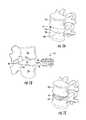
- FIG. 1Ais a perspective view of a pair of vertebral bodies separated by an intervertebral space
- FIG. 1Bis a side elevation view illustrating the insertion of an intervertebral implant into the intervertebral space between the two vertebral bodies of FIG. 1A ;
- FIG. 1Cis a perspective view of the vertebral bodies of FIGS. 1A and 1B with an intervertebral implant inserted into the intervertebral space;
- FIG. 2Ais a perspective view of the intervertebral implant illustrated in FIG. 1B which includes first and second endplates and an articulation disposed between the endplates;
- FIG. 2Bis a side elevation view of the intervertebral implant illustrated in FIG. 2A ;
- FIG. 3Ais a perspective view of an exemplary implementation of an implant holder clamp utilized by several implant holder embodiments disclosed herein;
- FIG. 3Bis a top elevation view of the exemplary implementation of the clamp of FIG. 3A ;
- FIG. 3Cis a side elevation view of the exemplary implementation of the clamp of FIGS. 3A and 3B ;
- FIG. 4Ais a perspective view of the implant holder clamp of FIGS. 3A, 3B, and 3C being coupled to an intervertebral implant of FIGS. 2A and 2B (the latter still housed in sterile packaging);
- FIG. 4Bis a top view of the implant holder coupled to the intervertebral implant (and together removed from the sterile packaging of FIG. 4A );
- FIG. 4Cis a side elevation view of the implant holder coupled to the intervertebral implant illustrated in FIG. 4B ;
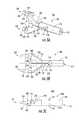
- FIG. 5a top view of an exemplary implementation of an implant holder sleeve (or guide member) utilized by several implant holder embodiments disclosed herein;
- FIG. 6a top view of an exemplary implementation of an implant holder shaft (or rotation member) utilized by several implant holder embodiments disclosed herein;
- FIG. 7is a top view of the shaft of FIG. 6 translationally and rotationally coupled with the sleeve of FIG. 5 ;
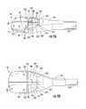
- FIG. 8Ais top view of the sleeve and shaft combination of FIG. 7 coupled to the clamp and implant combination of FIGS. 4B and 4C in an unlocked configuration;
- FIG. 8Bis top view of the distal end of the sleeve and shaft combination coupled to the clamp and implant combination in the unlocked configuration illustrated in FIG. 8A ;
- FIG. 9Ais perspective view of the implant and the distal end of the implant holder (comprising the clamp, sleeve, and shaft) of FIGS. 8A and 8B in a locked configuration;
- FIG. 9Bis top view of the implant and the distal end of the implant holder (comprising the clamp, sleeve, and shaft) in the locked configuration illustrated in FIG. 9A ;
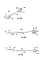
- FIG. 10Ais a perspective view of an exemplary implementation of an implant holder emplacement stop system utilized by certain implant holder embodiments disclosed herein;
- FIG. 10Bis a side elevation view of the exemplary implementation of the stop system of FIG. 10A ;
- FIG. 10Cis a top elevation view of the exemplary implementation of the stop system of FIGS. 10A and 10B ;
- FIG. 11Ais a perspective view of the exemplary implementation of an implant holder emplacement stop system of FIGS. 10A, 10B, and 10C connectively coupled to the top side of the implant holder sleeve of FIG. 5 ;
- FIG. 11Bis a perspective view of the exemplary implementation of an implant holder emplacement stop system of 11 A in an alternative configuration connectively coupled to the bottom side of the implant holder sleeve;
- FIG. 11Cis a perspective view of the proximal end of the stop system illustrated in FIG. 11A ;
- FIG. 12is an operational flow diagram illustrating a method for emplacing an implant using certain embodiments of the implant holder disclosed herein.
- various componentsare described herein as extending horizontally along a longitudinal direction “L” and lateral direction “A”, and vertically along a transverse direction “T”.
- the terms “lateral”, “longitudinal”, and “transverse”are used to describe the orthogonal directional components of various items. It should be appreciated that while the longitudinal and lateral directions are illustrated as extending along a horizontal plane, and that the transverse direction is illustrated as extending along a vertical plane, the planes that encompass the various directions may differ during use.
- the transverse direction Textends generally along the superior-inferior (or caudal-cranial) direction, while the plane defined by the longitudinal direction L and the lateral direction A lie generally in the anatomical plane defined by the anterior-posterior direction and the medial-lateral direction.
- the directional terms “vertical” and “horizontal”are used to describe the components merely for the purposes of clarity and illustration and are not meant to be limiting.
- FIG. 1Ais a perspective view of a pair of vertebral bodies 12 a and 12 b separated by an intervertebral space 14 .
- FIG. 1Bis a side elevation view illustrating the insertion of an intervertebral implant 10 into the intervertebral space 14 between the two vertebral bodies 12 a and 12 b of FIG. 1A .
- FIG. 1Cis a perspective view of the vertebral bodies 12 a and 12 b of FIGS. 1A and 1B with the intervertebral implant 10 inserted into the intervertebral space 14 .
- a superior vertebral body 12 adefines a superior vertebral surface 15 a of an intervertebral space 14
- an adjacent inferior vertebral body 12 bdefines an inferior vertebral surface 15 b of the intervertebral space 14
- the intervertebral space 14may be created by a discectomy where the disc material (not shown) normally found between the two vertebral bodies 12 a and 12 b has been removed to prepare the intervertebral space 14 to receive an orthopedic implant such as, for example, the intervertebral implant 10 .
- the implant 10is aligned with the intervertebral space 14 .
- the vertebral bodies 12 a and 12 bare retracted such that the anterior ends 96 of the vertebral bodies are separated generally along the caudal-cranial dimension a distance greater than the posterior ends 98 of the vertebral bodies 12 a and 12 b are separated.
- the implant 10may then be inserted into the intervertebral space 14 to achieve restoration of “height” (that is, anatomically correct separation of the superior vertebral surface 15 a from inferior vertebral surface 15 b ) while maintaining mobility.
- FIG. 2Ais a perspective view of the intervertebral implant 10 illustrated in FIG. 1B which includes first and second endplates ( 20 and 22 respectively) together forming an articulation disposed between the endplates.
- FIG. 2Bis a side elevation view of the intervertebral implant illustrated in FIG. 2A .
- the implant 10may include a first or upper component, such as a first or upper endplate 20 adapted to engage the superior vertebral body 12 a , and a second or lower component, such as a second or lower endplate 22 adapted to engage the inferior vertebral body 12 b .
- the endplates 20 and 22each carry complementary first and second joint members 75 and 77 , respectively, that provide rounded mating surfaces (concave for joint member 75 and convex for joint member 77 ) in operative contact with each other so as to provide an articulating joint that allows the endplates 20 and 22 360-degree universal movement relative to each other.
- the upper and lower endplates 20 and 22can thus pivot relative to each other about a lateral axis, for instance to accommodate flexions and extensions of the vertebrae 12 a and 12 b .
- the upper and lower endplates 20 and 22can pivot relative to each other about a longitudinal axis, for instance to accommodate lateral bending of the vertebrae 12 a and 12 b .
- the pivot axiscan also lie in any orientation within the horizontal plane defined by the longitudinal and lateral directions.
- the upper endplate 20also comprises an upper endplate body 21 that defines a longitudinally front end 23 , which provides a leading end with respect to insertion of the implant 10 into the intervertebral disc space 14 .
- the upper endplate body 21further defines an opposing longitudinal rear end 25 , which provides a trailing end with respect to insertion of the implant 10 into the intervertebral disc space 14 .
- the upper endplate body 21further defines opposing first and second lateral sides 27 and 29 , respectively, connected between the front and rear ends 23 and 25 respectively.
- the upper endplate body 21further presents an upper (or outer) transverse bone facing surface 24 , and an opposing lower (or inner) transverse surface 43 .
- the upper endplate 20includes a plurality of bone fixation spikes 39 projecting transversely outward, or up, from the bone facing surface 24 of the upper endplate body 21 .
- the lower endplate 22also comprises a lower endplate body 37 that defines a longitudinally front end 47 , which provides a leading end with respect to insertion of the implant 10 into the intervertebral disc space 14 .
- the lower endplate body 37further defines an opposing longitudinal rear end 31 , which provides a trailing end with respect to insertion of the implant 10 into the intervertebral disc space 14 .
- the lower endplate body 37further defines opposing first and second lateral sides 33 and 35 , respectively, connected between the front and rear ends 47 and 31 respectively.
- the lower endplate body 37further presents a lower (or outer) transverse bone facing surface 26 , and an opposing upper (or inner) transverse surface 45 .
- the lower endplate 22includes a plurality of bone fixation spikes 41 projecting transversely outward, or down, from the bone facing surface 26 of the lower endplate body 37 .
- the front ends 23 and 47 of the endplates 20 and 22define the front end 11 of the implant 10 corresponding to the posterior of the intervertebral space 14 for emplacement, while the rear ends 25 and 31 of the endplates 20 and 22 define the back end 13 of the implant 10 corresponding to the opposing anterior of the intervertebral space 14 for emplacement. Otherwise stated, the front end 11 is emplaced into the posterior region (proximate to posterior ends 98 ) of the intervertebral space 14 and the back end 13 is emplaced into the anterior region (proximate to anterior ends 96 ) of the intervertebral space 14 .
- the upper endplate 20includes laterally opposing notches 85 that are external engagement features extending into the rear end 25 of the endplate body 21 that are sized and shaped to receive the upper portion of the distal end of an insertion tool (or implant holder) configured to insert the implant into an intervertebral space.
- the lower endplate 22includes laterally opposing notches 87 extending into the rear end 31 of the endplate body 37 that are sized and shaped to receive the lower portion of an insertion tool configured to insert the implant 10 into an intervertebral space.
- the spikes 39 and 41initially slide freely into the intervertebral space 14 , and prior to full insertion begin to bite into the respective vertebral surfaces 15 a and 15 b .
- the retraction of the vertebral bodies 12 a and 12 bis released, thereby causing the surfaces 15 a and 15 b to return to their normal direction of extension, whereby the spikes 39 and 41 project into the vertebral surfaces 15 a and 15 b.
- an implant holder or insertion toolmay be used to emplace the vertebral implant 10 .
- the implant 10is fixed to the implant holder, and then the surgeon directly manipulates the implant holder to emplace the implant 10 (without ever directly touching the implant in some embodiments).
- the surgeonuses X-rays to check position of the implant 10 (typically in profile) to see whether the implant 10 is properly placed or whether it must still be further maneuvered into a better position, and the surgeon adjusts the implants position as necessary by continuing to manipulate the implant holder.
- the implant holderis then detached from the implant 10 and withdrawn, leaving behind the emplaced implant 10 .
- Various implant holdersare disclosed herein comprise three functional components: a clamp, a sleeve, and a shaft. While these components are disclosed as distinct, separate, and interchangeable pieces that can be operatively coupled together for utilization, it will be readily understood and appreciated that these three functional components can also be formed as a single tool wherein the components are inseparable, or as a two-part tool wherein any two of the three operational components are formed as a single item. Similarly, an optional fourth component—an emplacement stop system—is also herein disclosed as a separate fourth piece for use with the implant holder but which can also be formed as part of the implant holder (namely the sleeve). Accordingly, nothing herein is intended to limit the embodiments described herein to separable components but, instead, a single formed piece may comprise one or more than one of the operational components described herein.
- FIG. 3Ais a perspective view of an exemplary implementation of an implant holder clamp 100 (or clamp) utilized by several implant holder embodiments disclosed herein.
- FIG. 3Bis a top elevation view of the exemplary implementation of the clamp 100 of FIG. 3A .
- FIG. 3Cis a side elevation view of the exemplary implementation of the clamp 100 of FIGS. 3A and 3B .
- the implant holder clamp 100essentially comprises a U-shaped fork with two arms 102 and 104 fixedly coupled to a stem 106 .
- the stem 106may comprise a substantially solid rod 110 with a shallow threaded hole 112 at the proximal end for attaching to the threaded end of a shaft.
- the stemis also fixedly coupled to each arm 102 and 104 proximate to a flexion hole 114 .
- the arms 102 and 104are separated from each other by the flexion hole 114 and by a lateral gap 118 running from the flexion hole 114 to the distal end of the clamp 100 .
- each arm 102 and 104comprises a flexion portion 116 —in part formed by the flexion hole 114 —which provides the arms 102 and 104 with limited flexibility such that they can be moved toward or away from each other relative to their resting position (as illustrated) with the application of force (which also has the effect of decreasing or increasing the width of the lateral gap 118 running between the arms 102 and 104 ).
- the amount of force necessary to slightly separate the two arms 102 and 104is dependent upon the thickness of the flexion portion 116 and the material from which the flexion portions (and, ostensibly, the entire stem) is made.
- the amount of force requiredis low enough to enable a surgeon of ordinary strength and dexterity to affix an implant 10 onto the arms 102 and 104 of the implant holder clamp 100 as well as enable the implant 10 to detach and remain in position when emplaced in the intervertebral space 14 as the implant holder clamp 100 is withdrawn using a retraction force applied by the surgeon, but yet high enough to prevent the implant 10 from becoming inadvertently detached from the implant holder clamp 100 such as while the implant 10 is being emplaced in a forward longitudinal direction using the implant holder clamp 100 .
- This forceis hereafter referred to as a “surgeon force” and an implant 10 that is attached and detached to an implant holder clamp 100 using surgeon force is said to be “loosely coupled.”
- surgeon forcean implant 10 that is attached and detached to an implant holder clamp 100 using surgeon force is said to be “loosely coupled.”
- implantcannot be decoupled from the implant holder using surgeon force, the implant is said to be “fixedly coupled.”
- each arm 102 and 104further comprises a central body 120 featuring two of four clamping elements 132 (one superior and one inferior), half of a U-shaped central spacer 130 , and one of a pair of locking surfaces 126 , and a projection extending from and contained on each of the pair of locking surfaces.
- the four central-projecting clamping elements 132are able to engage the notches 85 and 87 of the implant device 10 with the application of surgeon force as previously described.
- each arm 102 and 104enable the application of a locking force (for example, by operation of the shaft and sleeve discussed later herein) to fixedly couple the implant 10 to the clamp 100 by preventing the arms 102 and 104 from flexibly opening.
- the U-shaped central spacer 130 formed by both arms 102 and 104semi-circumferentially abut against the convex joint member 77 of the articulating joint of the implant 10 as well as the upper and lower endplates 20 and 22 in order to maintain in parallel the lower (or inner) transverse surface 43 of the upper endplate 20 and the upper (or inner) transverse surface 45 of the lower endplate 22 to give temporary solidity to the implant 10 during its emplacement.
- each armalso comprises an optical control channel 122 on the upper surface of the arms 102 and 104 to enable the surgeon to visually gauge the location of the back end 13 of the implant 10 when the surgeon uses X-rays to check position of the implant 10 in profile (or laterally).
- this optical control channel 122provides an X-ray-visible feature that enables the surgeon to differentiate between the two components and better determine how far the back end 13 of the implant 10 is embedded (or “implanted” or “emplaced”) in the intervertebral space 14 .
- the optical control channel 122may simply comprise a straight line-of-sight channel (with the arms in the resting position) or, alternatively, it may be coated or filled with X-ray reflective or deflective material to make it even more easily identified using an X-ray.
- the channelmay also be shaped differently—such as, for example, narrower medially but wider laterally to provide a less-specific by easier-to-identify reference point—and/or the clamp 100 may comprise more than one channel—such as, for example, a second optical control channel running on the lower endplate running parallel to the first optical control channel 122 .
- FIG. 4Ais a perspective view of the implant holder clamp 100 of FIGS. 3A, 3B, and 3C being coupled to an intervertebral implant 10 of FIGS. 2A and 2B (the latter still housed in sterile packaging 400 .
- FIG. 4Bis a top view of the implant holder 100 coupled to the intervertebral implant 10 (and together removed from the sterile packaging 400 of FIG. 4A ).
- FIG. 4Cis a side elevation view of the implant holder 10 coupled to the intervertebral implant 10 illustrated in FIG. 4B . Referring to FIGS. 4A, 4B , and 4 C (collectively referred to herein as “ FIG.
- the implant 10is removed from its sterile packing longitudinally moving the implant holder 100 with surgeon force to loosely couple with the implant and then retracting the implant holder 100 and the implant 10 from the packaging—which, as illustrated, may be accomplished without the person performing the coupling directly touching the implant 10 .
- FIG. 4Bit should be noted that the left edge of the optical control channel 122 of the implant holder 100 is substantially aligned with the back end 13 of the implant 10 such that the back end 13 of the implant can be accurately determined by locating the optical control channel 122 during the surgeon's aforementioned X-ray checks.
- FIG. 5a top view of an exemplary implementation of an implant holder sleeve (or guide member) 200 utilized by several implant holder embodiments disclosed herein.
- the sleeve 200comprises a hollow body 210 featuring, at its proximal end, an attachment surface 240 , a service collar 212 , and the proximal opening of the hollow channel 214 running the length of the sleeve 200 .
- the attachment surface 240may be used for mounting supplemental devices to the sleeve 200 (such as the stop system discussed later herein, for example).
- the hollow body 210features a clamp coupler 216 which in turn comprises two locking tines 220 and the distal opening of the hollow channel 214 in a terminus surface 218 .
- the two locking tines 220each comprise a locking surface 222 that are together geometrically angled to substantially match the geometric angle of the two locking surfaces 126 of the implant holder clamp 100 .
- Each of the locking surfaces 222can include a recess for receiving the corresponding projection extending from locking surfaces 126 .
- FIG. 6a top view of an exemplary implementation of an implant holder shaft 300 (or rotation member) utilized by several implant holder embodiments disclosed herein.
- the sleeve 200comprises a rod 310 featuring, at its proximal end, an in-hole stabilizer 314 , a mating collar 312 , and a rotation knob 316 .
- the rod 210further comprises a threaded post 318 for engaging the threaded hole 112 of the implant holder clamp 100 .
- FIG. 7is a top view of the shaft 300 of FIG. 6 translationally and rotationally coupled with the sleeve 200 of FIG. 5 , such that the distal end of the shaft (featuring the threaded post 318 ) is inserted through the proximal opening of the hollow channel 214 and runs the length of the sleeve 200 to distal end, wherein the sleeve 200 circumferentially and encloses the distal and medial portions of the shaft 300 .
- FIG. 8Ais top view of the sleeve 200 and shaft 300 combination of FIG. 7 (also referred to herein as the “locking mechanism”) coupled to the clamp 100 and implant 10 combination of FIGS. 4B and 4C in an unlocked configuration.
- FIG. 8Bis top view of the distal end of the sleeve and shaft combination coupled to the clamp and implant combination in the unlocked configuration illustrated in FIG. 8A . Referring to FIGS. 8A and 8B (collectively referred to herein as “ FIG.
- the stem 110 (not shown) of the implant holder 100movably resides in the distal opening of the hollow channel 214 proximate to the terminus surface 218 of the sleeve 200 , and the threaded hole 112 of the implant holder 100 is partially coupled to the threaded post 318 of the shaft 300 .
- the threaded post 318will continue draw the stem 110 (not shown) into the hollow channel 214 and move the implant holder 100 and its pair of locking surfaces 126 closer and closer to the clamp coupler 216 and its locking surfaces 222 .
- rotating the shaft 300 within the sleeve 200permits the surgeon (or a skilled assistant) to selectively determine to lock or unlock the clamp 100 which, in turn, determines whether the implant 10 is fixedly coupled (when locked) or loosely coupled (when unlocked) to the clamp 100 .
- FIG. 9Ais perspective view of the implant 10 and the distal end of the implant holder (comprising the clamp 100 , sleeve 200 , and shaft 300 ) of FIGS. 8A and 8B in a locked configuration.
- FIG. 8Bis top view of the implant 10 and the distal end of the implant holder (comprising the clamp 100 , sleeve 200 , and shaft 300 ) in the locked configuration illustrated in FIG. 9A .
- FIGS. 9A and 9B(collectively referred to herein as “ FIG.
- the stem 110 (not shown) of the implant holder 100has been maximally retracted into the distal opening of the hollow channel 214 proximate to the terminus surface 218 of the sleeve 200 by rotation of the threaded post 318 via the rotation knob 316 .
- the implant holder's 100 pair of locking surfaces 126are in direct contact with the clamp coupler's 216 locking surfaces 222 which, in turn, prevents the arms 102 and 104 (not shown) and their corresponding clamping elements 132 from flexibly opening and decoupling from the implant 10 —that is, the implant 10 is “locked” or fixedly coupled to the clamp 100 of the implant holder (i.e., in a “locked position”).
- surgeonmay emplace, move, and even withdraw the implant 10 and implant holder clamp 100 using surgeon force without leaving the implant 10 behind (as would be the case in an unlocked configuration) or risking the implant 10 from becoming inadvertently decoupled from the clamp 100 .
- the surgeonmerely rotates the shaft 200 in a loosening direction opposite the tightening direction (via the rotation knob 316 ) to separate the locking surfaces 126 of the implant holder clamp 100 from the locking surfaces 222 of the implant holder sleeve 200 and again return to a configuration akin to that shown in FIG. 8 , in which instance the implant 10 is again only loosely coupled to the clamp 100 and can be removed by surgeon force from the clamp 100 .
- FIG. 10Ais a perspective view of an exemplary implementation of an implant holder emplacement stop system 500 utilized by certain implant holder embodiments disclosed herein.
- FIG. 10Bis a side elevation view of the exemplary implementation of the stop system 500 of FIG. 10A .
- FIG. 10Cis a top elevation view of the exemplary implementation of the stop system of FIGS. 10A and 10B .
- the stop systemcomprises a clip 502 for clipping to an attachment surface 240 of an implant holder sleeve 200 and rotatably mounting a threaded rotor 504 engaging the threaded proximal end 506 ′ of a stop body 506 .
- the distal end of the stop body 506is coupled to a slidable sleeve 508 that, in turn, is coupled to a stop rod 510 ending in a stop surface 512 comprising the most distal end of the stop system 500 .
- the stop system 512may be used to reduce risk of penetration into spinal canal during the implantation procedure.
- FIG. 11Ais a perspective view of the exemplary implementation of an implant holder emplacement stop system of FIGS. 10A, 10B, and 10C connectively coupled to the top side of the implant holder sleeve 200 of FIG. 5 .
- FIG. 11Bis a perspective view of the exemplary implementation of an implant holder emplacement stop system of 11 A in an alternative configuration connectively coupled to the bottom side of the implant holder sleeve.
- FIG. 11Cis a perspective view of the proximal end of the stop system illustrated in FIG. 11A . Referring to FIGS. 11A, 11B, and 11C (collectively referred to herein as “ FIG.
- the surgeoncan longitudinally move the stop 512 to correspond to a desired depth such that when used, the stop will abut up against the anterior surface of a vertebrae (such as superior vertebral body 12 a ) and prevent the implant 10 from being emplaced any deeper into the intervertebral space 14 .
- a vertebraesuch as superior vertebral body 12 a
- FIG. 12is an operational flow diagram illustrating a method for emplacing an implant 10 using certain embodiments of the implant holder disclosed herein.
- the surgeon(or a qualified assistant) couples the shaft 300 to the sleeve 200 by inserting the shaft 300 into the sleeve 200 as previously discussed herein.
- the surgeonalso couples (that is, loosely couples in an unlocked configuration) the clamp 100 to the implant 10 .
- the surgeoncoupled the clamp 100 and implant 10 combination to the sleeve 200 and shaft 300 combination (or “locking mechanism”) which initially is still in the unlocked configuration (or “unlocked position”).
- the surgeoncould first couple the clamp, sleeve, and shaft in an unlocked configuration, and then couple this three-part assembly to the implant.
- this three-part assemblythere are several ways in which each of the clamp 100 , sleeve 200 , shaft 300 , and implant 10 are coupled, and thus the order presented in FIG. 12 is only exemplary and is in no way limiting.
- the surgeonthen locks the implant 10 into the implant holder by engaging the locking surfaces 126 of the clamp 100 with the locking surfaces 222 of the sleeve 200 and, at 610 , the surgeon then proceeds to emplace the implant 10 using the assembled implant holder (with or without the optional stop system 500 ). After emplacing the implant 10 , the surgeon then uses X-rays (and the optical control channel 122 as an X-ray-visible reference point) to determine if the implant is emplaced in a suitable location. If not (as determined at 614 ), at 624 the surgeon reiteratively re-emplaces the implant 10 by continuing to manipulate the implant 10 via the implant holder and, returning to 612 , checking implant 10 until it is properly emplaced.
- the implant 10 and implant holderare unlocked and, at step 618 , the implant holder is withdrawn (or retracted) using surgeon force.
- the implant holderis withdrawn (or retracted) using surgeon force.
- the implantshould remain embedded and, if so, the surgeon can then conclude the embedding portion of the procedure.
- the surgeonneeds to re-emplace the implant (or a different implant) at step 624 and continue again from there.
- the various components described hereincan be formed from a variety of biocompatible materials, such as cobalt chromium molybdenum (CoCrMo), titanium and titanium alloys, stainless steel or other metals, as well as ceramics or polymers such as polyetheretherketone (PEEK), polyetherketoneketone (PEKK), bioresorbable materials, and bonegraft (for example allograft and xenograft).
- a coatingmay be added or applied to the various components described herein to improve physical or chemical properties, or to help ensure bony in or on growth of medication. Examples of coatings include plasma-sprayed titanium coating or Hydroxypatite.
- any intervertebral space along the spineand, in addition to use as a disc replacement device, are also readily configurable for use with a range of bone-anchored orthopedic prostheses, such as a spinal fusion implant, an interbody spacer, an intervertebral cage, a corpectomy device, hip and knee replacement implants, long bone replacement plates, intramedulary nails and rods, bone fixation plates (such as for fixation of craniomaxillofacial fractures), veterinary implants, and tips for guide wires, and the like.
- bone-anchored orthopedic prosthesessuch as a spinal fusion implant, an interbody spacer, an intervertebral cage, a corpectomy device, hip and knee replacement implants, long bone replacement plates, intramedulary nails and rods, bone fixation plates (such as for fixation of craniomaxillofacial fractures), veterinary implants, and tips for guide wires, and the like.
Landscapes
- Health & Medical Sciences (AREA)
- Engineering & Computer Science (AREA)
- Biomedical Technology (AREA)
- Orthopedic Medicine & Surgery (AREA)
- Transplantation (AREA)
- Neurology (AREA)
- Oral & Maxillofacial Surgery (AREA)
- Cardiology (AREA)
- Heart & Thoracic Surgery (AREA)
- Vascular Medicine (AREA)
- Life Sciences & Earth Sciences (AREA)
- Animal Behavior & Ethology (AREA)
- General Health & Medical Sciences (AREA)
- Public Health (AREA)
- Veterinary Medicine (AREA)
- Physical Education & Sports Medicine (AREA)
- Prostheses (AREA)
Abstract
Description
Claims (22)
Priority Applications (1)
| Application Number | Priority Date | Filing Date | Title |
|---|---|---|---|
| US13/081,541US9301853B2 (en) | 2010-04-09 | 2011-04-07 | Holder for implantation and extraction of prosthesis |
Applications Claiming Priority (2)
| Application Number | Priority Date | Filing Date | Title |
|---|---|---|---|
| US12/757,443US8858636B2 (en) | 2010-04-09 | 2010-04-09 | Intervertebral implant |
| US13/081,541US9301853B2 (en) | 2010-04-09 | 2011-04-07 | Holder for implantation and extraction of prosthesis |
Related Parent Applications (1)
| Application Number | Title | Priority Date | Filing Date |
|---|---|---|---|
| US12/757,443Continuation-In-PartUS8858636B2 (en) | 2010-04-09 | 2010-04-09 | Intervertebral implant |
Publications (2)
| Publication Number | Publication Date |
|---|---|
| US20110301612A1 US20110301612A1 (en) | 2011-12-08 |
| US9301853B2true US9301853B2 (en) | 2016-04-05 |
Family
ID=45065036
Family Applications (1)
| Application Number | Title | Priority Date | Filing Date |
|---|---|---|---|
| US13/081,541ActiveUS9301853B2 (en) | 2010-04-09 | 2011-04-07 | Holder for implantation and extraction of prosthesis |
Country Status (1)
| Country | Link |
|---|---|
| US (1) | US9301853B2 (en) |
Cited By (14)
| Publication number | Priority date | Publication date | Assignee | Title |
|---|---|---|---|---|
| US20160051371A1 (en)* | 2014-08-19 | 2016-02-25 | Scott DeFelice | Spinal implant and method for fabricating the same |
| US20180200078A1 (en)* | 2017-01-18 | 2018-07-19 | Neuropro Technologies, INC | Bone fusion surgical system and method |
| US10420654B2 (en) | 2011-08-09 | 2019-09-24 | Neuropro Technologies, Inc. | Bone fusion device, system and method |
| US10575966B2 (en) | 2013-03-15 | 2020-03-03 | Neuropro Technologies, Inc. | Bodiless bone fusion device, apparatus and method |
| US10682240B2 (en) | 2004-11-03 | 2020-06-16 | Neuropro Technologies, Inc. | Bone fusion device |
| US10709574B2 (en) | 2012-04-13 | 2020-07-14 | Neuropro Technologies, Inc. | Bone fusion device |
| US10729562B2 (en) | 2017-01-18 | 2020-08-04 | Neuropro Technologies, Inc. | Bone fusion system, device and method including a measuring mechanism |
| US10729560B2 (en) | 2017-01-18 | 2020-08-04 | Neuropro Technologies, Inc. | Bone fusion system, device and method including an insertion instrument |
| US10736754B2 (en) | 2011-08-09 | 2020-08-11 | Neuropro Spinal Jaxx, Inc. | Bone fusion device, apparatus and method |
| USD894385S1 (en) | 2017-10-27 | 2020-08-25 | Orthopediatrics Corp. | Orthopedic tool |
| US11141289B2 (en) | 2017-01-18 | 2021-10-12 | Neuropro Technologies, Inc. | Bone fusion system, device and method including delivery apparatus |
| US11432940B2 (en) | 2011-08-09 | 2022-09-06 | Neuropro Technologies, Inc. | Bone fusion device, system and method |
| US11439451B2 (en) | 2017-06-23 | 2022-09-13 | Orthopediatrics Corp. | Insertion apparatus for an intramedullary nail |
| US11464652B2 (en)* | 2010-04-21 | 2022-10-11 | Globus Medical, Inc. | Insertion tool assembly |
Families Citing this family (10)
| Publication number | Priority date | Publication date | Assignee | Title |
|---|---|---|---|---|
| US8591587B2 (en) | 2007-10-30 | 2013-11-26 | Aesculap Implant Systems, Llc | Vertebral body replacement device and method for use to maintain a space between two vertebral bodies within a spine |
| US8142441B2 (en)* | 2008-10-16 | 2012-03-27 | Aesculap Implant Systems, Llc | Surgical instrument and method of use for inserting an implant between two bones |
| US8858636B2 (en) | 2010-04-09 | 2014-10-14 | DePuy Synthes Products, LLC | Intervertebral implant |
| US9572684B2 (en)* | 2012-12-26 | 2017-02-21 | Innovasis, Inc. | Interbody insertion tool and method |
| WO2014145766A1 (en)* | 2013-03-15 | 2014-09-18 | Paradigm Spine, Llc | Modular, customizable spine stabilization system |
| CN103293057B (en)* | 2013-06-04 | 2015-10-28 | 南京航空航天大学 | Based on the unit clamp for the torture test of cervical artificial disc prosthese of bionics principle |
| IL255796A0 (en)* | 2017-11-21 | 2017-12-31 | E K D D S Ltd | Handheld implantation devices for implantation of retinal tissue implant |
| US20150230926A1 (en) | 2014-02-18 | 2015-08-20 | Biomet Manufacturing, Llc | Method and device for reducing implant contamination from handling |
| US11219536B2 (en)* | 2019-05-01 | 2022-01-11 | Simplify Medical Pty Ltd | Intervertebral prosethetic disc placement and removal systems |
| US11452618B2 (en) | 2019-09-23 | 2022-09-27 | Dimicron, Inc | Spinal artificial disc removal tool |
Citations (107)
| Publication number | Priority date | Publication date | Assignee | Title |
|---|---|---|---|---|
| US2549731A (en)* | 1944-12-18 | 1951-04-17 | Vincent E Wattley | Flexible test prod |
| US4877020A (en)* | 1984-11-30 | 1989-10-31 | Vich Jose M O | Apparatus for bone graft |
| US4997432A (en)* | 1988-03-23 | 1991-03-05 | Waldemar Link Gmbh & Co. | Surgical instrument set |
| US5071437A (en) | 1989-02-15 | 1991-12-10 | Acromed Corporation | Artificial disc |
| US5306309A (en) | 1992-05-04 | 1994-04-26 | Calcitek, Inc. | Spinal disk implant and implantation kit |
| US5443514A (en)* | 1993-10-01 | 1995-08-22 | Acromed Corporation | Method for using spinal implants |
| US5522899A (en) | 1988-06-28 | 1996-06-04 | Sofamor Danek Properties, Inc. | Artificial spinal fusion implants |
| US5676701A (en) | 1993-01-14 | 1997-10-14 | Smith & Nephew, Inc. | Low wear artificial spinal disc |
| US5888227A (en) | 1995-10-20 | 1999-03-30 | Synthes (U.S.A.) | Inter-vertebral implant |
| US6066174A (en)* | 1995-10-16 | 2000-05-23 | Sdgi Holdings, Inc. | Implant insertion device |
| WO2000049977A1 (en) | 1999-02-26 | 2000-08-31 | Williams Lytton A | Method and apparatus for intervertebral implant anchorage |
| US6159215A (en)* | 1997-12-19 | 2000-12-12 | Depuy Acromed, Inc. | Insertion instruments and method for delivering a vertebral body spacer |
| US6267763B1 (en) | 1999-03-31 | 2001-07-31 | Surgical Dynamics, Inc. | Method and apparatus for spinal implant insertion |
| US20010019816A1 (en) | 1999-08-12 | 2001-09-06 | Ajay Kumar | Universal implant delivery system |
| US6319257B1 (en)* | 1999-12-20 | 2001-11-20 | Kinamed, Inc. | Inserter assembly |
| US6416551B1 (en) | 1999-05-21 | 2002-07-09 | Waldemar Link (Gmbh & Co.) | Intervertebral endoprosthesis with a toothed connection plate |
| US6440168B1 (en) | 1998-04-23 | 2002-08-27 | Sdgi Holdings, Inc. | Articulating spinal implant |
| US6440142B1 (en) | 2001-04-27 | 2002-08-27 | Third Millennium Engineering, Llc | Femoral ring loader |
| US6517580B1 (en) | 2000-03-03 | 2003-02-11 | Scient'x Societe A Responsabilite Limited | Disk prosthesis for cervical vertebrae |
| US6740118B2 (en) | 2002-01-09 | 2004-05-25 | Sdgi Holdings, Inc. | Intervertebral prosthetic joint |
| US20040147937A1 (en)* | 2003-01-24 | 2004-07-29 | Depuy Spine, Inc. | Spinal rod approximators |
| US20040172133A1 (en) | 2001-05-03 | 2004-09-02 | Synthes(U.S.A.) | Intervertebral Implant for transforaminal posterior lumbar interbody fusion procedure |
| US6827740B1 (en) | 1999-12-08 | 2004-12-07 | Gary K. Michelson | Spinal implant surface configuration |
| US20040254643A1 (en) | 2002-11-12 | 2004-12-16 | Jackson Roger P. | Articulated anterior expandable spinal fusion cage system |
| US20050021042A1 (en)* | 2003-07-21 | 2005-01-27 | Theirry Marnay | Instruments and method for inserting an intervertebral implant |
| US20050033305A1 (en)* | 2003-07-08 | 2005-02-10 | Robert Schultz | Surgical instrument for handling an implant |
| US20050038445A1 (en)* | 2001-07-16 | 2005-02-17 | Errico Joseph P. | Instrumentation for repositioning and extracting an artificial intervertebral disc from an intervertebral space |
| US20050131544A1 (en) | 2003-12-10 | 2005-06-16 | Axiomed Spine Corporation | Method and apparatus for replacing a damaged spinal disc |
| US20050143749A1 (en)* | 2003-12-31 | 2005-06-30 | Depuy Spine, Inc. | Inserter instrument and implant clip |
| US6936071B1 (en) | 1999-07-02 | 2005-08-30 | Spine Solutions, Inc. | Intervertebral implant |
| US20050197706A1 (en) | 2004-02-04 | 2005-09-08 | Ldr Medical, Inc. | Intervertebral disc prosthesis |
| EP1587461A2 (en) | 2003-01-17 | 2005-10-26 | Manoj Krishna | Articulating spinal disc prosthesis |
| US20050240267A1 (en) | 2004-03-26 | 2005-10-27 | Randall Brandon L | Allograft implant |
| US20050251260A1 (en) | 2002-08-15 | 2005-11-10 | David Gerber | Controlled artificial intervertebral disc implant |
| US6966929B2 (en) | 2002-10-29 | 2005-11-22 | St. Francis Medical Technologies, Inc. | Artificial vertebral disk replacement implant with a spacer |
| US20050273171A1 (en) | 2003-08-05 | 2005-12-08 | Gordon Charles R | Method of inserting an expandable intervertebral implant without overdistraction |
| US20050288788A1 (en) | 2004-06-25 | 2005-12-29 | Gretchen Dougherty-Shah | Intervertebral implant and associated method |
| US20060025777A1 (en)* | 2004-07-28 | 2006-02-02 | Helmut Weber | Surgical instrument for the introduction of a multi-component intervertebral prosthesis |
| US6994727B2 (en) | 2002-12-17 | 2006-02-07 | Amedica Corporation | Total disc implant |
| US20060030860A1 (en)* | 2004-07-23 | 2006-02-09 | Sdgi Holdings, Inc. | Artificial disc inserter |
| WO2006016384A1 (en) | 2004-08-12 | 2006-02-16 | Sintea Biotech S.P.A. | Disc prosthesis |
| US20060074418A1 (en)* | 2004-09-24 | 2006-04-06 | Jackson Roger P | Spinal fixation tool set and method for rod reduction and fastener insertion |
| US7051417B2 (en) | 1999-12-08 | 2006-05-30 | Sdgi Holdings, Inc. | Method for forming an orthopedic implant surface configuration |
| US20060129241A1 (en) | 2000-03-22 | 2006-06-15 | Synthes (Usa) | Skeletal reconstruction cages |
| US7105024B2 (en) | 2003-05-06 | 2006-09-12 | Aesculap Ii, Inc. | Artificial intervertebral disc |
| US20060235535A1 (en) | 1999-10-08 | 2006-10-19 | Ferree Bret A | Artificial disc and joint replacements with modular cushioning components |
| US20060293690A1 (en)* | 2005-05-23 | 2006-12-28 | Custom Spine, Inc. | Rod reducer |
| US20070010887A1 (en) | 2002-03-30 | 2007-01-11 | Williams Lytton A | Intervertebral Device and Method of Use |
| US20070013311A1 (en) | 2005-07-08 | 2007-01-18 | Moon Won S | Dielectric sheet, plasma display panel using the same, and manufacturing method therefor |
| US20070073311A1 (en)* | 2005-09-26 | 2007-03-29 | Williams Lytton A | System and method for intervertebral implant delivery and removal |
| US7198644B2 (en) | 2003-07-08 | 2007-04-03 | Aesculap Ag & Co. Kg | Intervertebral implant |
| US7204852B2 (en) | 2002-12-13 | 2007-04-17 | Spine Solutions, Inc. | Intervertebral implant, insertion tool and method of inserting same |
| US20070100347A1 (en) | 2005-10-31 | 2007-05-03 | Stad Shawn D | Arthroplasty revision device and method |
| US20070100455A1 (en) | 2005-10-31 | 2007-05-03 | Depuy Spine, Inc. | Method and apparatus for fixation of intervertebral disc prosthesis |
| US7217292B2 (en) | 2001-07-16 | 2007-05-15 | Spinecore, Inc. | Trial intervertebral distraction spacers |
| US20070112429A1 (en) | 2004-01-28 | 2007-05-17 | F3 Technologies, Llc | Artificial intervertebral disc |
| US7235103B2 (en) | 2004-01-13 | 2007-06-26 | Rivin Evgeny I | Artificial intervertebral disc |
| US20070156239A1 (en) | 2005-06-03 | 2007-07-05 | Zipnick Richard I | Minimally invasive apparatus to manipulate and revitalize spinal column disc |
| US7273496B2 (en) | 2002-10-29 | 2007-09-25 | St. Francis Medical Technologies, Inc. | Artificial vertebral disk replacement implant with crossbar spacer and method |
| US20070255416A1 (en) | 2006-05-01 | 2007-11-01 | Sdgi Holdings, Inc. | Intervertebral implants with covered inner chamber and methods of use |
| US20070255414A1 (en) | 2006-05-01 | 2007-11-01 | Sdgi Holdings, Inc. | Intervertebral implants with one or more covers and methods of use |
| US20070255407A1 (en) | 2006-04-27 | 2007-11-01 | Sdgi Holdings, Inc. | Self-contained expandable implant and method |
| US20070270956A1 (en) | 2006-04-13 | 2007-11-22 | Sdgi Holdings, Inc. | Vertebral fusion implants and methods of use |
| US7300465B2 (en) | 1998-01-30 | 2007-11-27 | Synthes (U.S.A.) | Intervertebral allograft spacer |
| US20070282441A1 (en) | 2006-05-19 | 2007-12-06 | Katie Stream | Spinal Stabilization Device and Methods |
| US20070299521A1 (en) | 2004-11-23 | 2007-12-27 | Glenn Bradley J | Minimally invasive spinal disc stabilizer and insertion tool |
| US20080015698A1 (en) | 2002-10-31 | 2008-01-17 | Marino James F | Spinal disc implant |
| US7331995B2 (en) | 2003-02-12 | 2008-02-19 | Sdgi Holdings, Inc. | Method for inserting an articular disc prosthesis via the transforaminal approach |
| US20080103598A1 (en) | 2006-09-15 | 2008-05-01 | Trudeau Jeffrey L | System and Method for Sizing, Inserting and Securing Artificial Disc in Intervertebral Space |
| US20080200984A1 (en)* | 2007-02-16 | 2008-08-21 | Ldr Medical | Intervertebral Disc Prosthesis Insertion Assemblies |
| US20080255574A1 (en)* | 2007-04-13 | 2008-10-16 | Zimmer Technology, Inc. | Instrument for insertion of prosthetic components |
| US7442211B2 (en) | 2003-05-27 | 2008-10-28 | Spinalmotion, Inc. | Intervertebral prosthetic disc |
| US20080275455A1 (en)* | 2006-08-16 | 2008-11-06 | Amicus, Llc | Apparatus and Methods for Inserting an Implant |
| US20080275447A1 (en)* | 2007-04-24 | 2008-11-06 | Depuy Products, Inc. | Assembly for minimally invasive reduction of hip fracture |
| US20080287957A1 (en)* | 2007-05-18 | 2008-11-20 | Depuy Spine, Inc. | Insertion blade assembly and method of use |
| US20080294173A1 (en) | 2007-05-25 | 2008-11-27 | Reeder Jr Ralph F | Radiolucent screwdriver for orthopedic surgery |
| US20080306488A1 (en)* | 2007-06-07 | 2008-12-11 | Moti Altarac | Inserter for a spinal implant |
| US20080306557A1 (en)* | 2007-06-11 | 2008-12-11 | Moti Altarac | Inserter for a spinal implant |
| US20090012529A1 (en) | 2007-07-02 | 2009-01-08 | Jason Blain | Device and method for delivery of multiple heterogenous orthopedic implants |
| US20090018661A1 (en) | 2003-08-01 | 2009-01-15 | Spinal Kinetics, Inc. | Prosthetic Intervertebral Discs |
| US20090030422A1 (en)* | 2007-07-23 | 2009-01-29 | Depuy Spine, Inc. | Implant insertion device and method |
| US20090030421A1 (en)* | 2007-07-23 | 2009-01-29 | Depuy Spine, Inc. | Implant engagement method and device |
| US7517363B2 (en) | 2002-06-27 | 2009-04-14 | Depuy Acromed, Inc. | Intervertebral disc having translation |
| US20090112217A1 (en) | 2007-10-31 | 2009-04-30 | Douglas Hester | Implant insertion device |
| US20090216330A1 (en)* | 2004-09-23 | 2009-08-27 | Christophe Geisert | System and method for an intervertebral implant |
| US20090228054A1 (en)* | 2008-01-29 | 2009-09-10 | Jeffrey Hoffman | Rod Locking Instrument |
| US20090254182A1 (en)* | 2008-04-02 | 2009-10-08 | John Kovarik | Intervertebral implant devices for supporting vertebrae and devices and methods for insertion thereof |
| US7618423B1 (en)* | 2002-06-15 | 2009-11-17 | Nuvasive, Inc. | System and method for performing spinal fusion |
| US20100023128A1 (en)* | 2008-07-23 | 2010-01-28 | Malberg Marc I | Modular nucleus pulposus prosthesis |
| US20100023019A1 (en)* | 2006-11-28 | 2010-01-28 | Spineart Sa | Prosthesis holder and application thereof |
| US20100042216A1 (en) | 2008-08-15 | 2010-02-18 | Pioneer Surgical Technology, Inc. | Implant for Deploying Bone Graft Material and Methods Thereof |
| US7686809B2 (en)* | 2006-09-25 | 2010-03-30 | Stryker Spine | Rod inserter and rod with reduced diameter end |
| US20100121388A1 (en)* | 2006-04-20 | 2010-05-13 | Eric Flickinger | Monorail System |
| US20100168803A1 (en)* | 2008-12-29 | 2010-07-01 | Zimmer Spine, Inc. | Flexible Guide for Insertion of a Vertebral Stabilization System |
| US20100191241A1 (en)* | 2008-06-06 | 2010-07-29 | Mccormack Bruce M | Vertebral joint implants and delivery tools |
| US20100249795A1 (en)* | 2009-03-30 | 2010-09-30 | Dimauro Thomas M | Cervical Motion Disc Inserter |
| US20100268343A1 (en) | 2009-04-16 | 2010-10-21 | Warsaw Orthopedic, Inc. | Vertebral endplate connection implant and method |
| US20100286778A1 (en) | 2007-04-18 | 2010-11-11 | Lukas Eisermann | Textile-Based Spinal Implant and Related Methods |
| US20100286784A1 (en)* | 2005-07-28 | 2010-11-11 | Matthew Curran | Total disc replacement system and related methods |
| US7846210B2 (en)* | 2007-01-16 | 2010-12-07 | Perez-Cruet Miguelangelo J | Minimally invasive interbody device assembly |
| US20100331901A1 (en)* | 2005-04-27 | 2010-12-30 | Andrew Iott | Percutaneous Vertebral Stabilization System |
| US20110015678A1 (en)* | 2004-11-23 | 2011-01-20 | Jackson Roger P | Spinal fixation tool set and method |
| US7891434B2 (en) | 2007-03-29 | 2011-02-22 | Baker Hughes Incorporated | Packer setting device for high hydrostatic applications |
| US20110251690A1 (en) | 2010-04-09 | 2011-10-13 | Roger Berger | Intervertebral implant |
| WO2011126490A1 (en) | 2010-04-09 | 2011-10-13 | Synthes Usa, Llc | Endplate of an intervertebral implant and implant |
| US8142435B2 (en)* | 2009-02-19 | 2012-03-27 | Aesculap Implant Systems, Llc | Multi-functional surgical instrument and method of use for inserting an implant between two bones |
| US20120150241A1 (en)* | 2010-12-13 | 2012-06-14 | Ragab Ashraf A | Bone Cage Placement Device |
- 2011
- 2011-04-07USUS13/081,541patent/US9301853B2/enactiveActive
Patent Citations (127)
| Publication number | Priority date | Publication date | Assignee | Title |
|---|---|---|---|---|
| US2549731A (en)* | 1944-12-18 | 1951-04-17 | Vincent E Wattley | Flexible test prod |
| US4877020A (en)* | 1984-11-30 | 1989-10-31 | Vich Jose M O | Apparatus for bone graft |
| US4997432A (en)* | 1988-03-23 | 1991-03-05 | Waldemar Link Gmbh & Co. | Surgical instrument set |
| US5522899A (en) | 1988-06-28 | 1996-06-04 | Sofamor Danek Properties, Inc. | Artificial spinal fusion implants |
| US5071437A (en) | 1989-02-15 | 1991-12-10 | Acromed Corporation | Artificial disc |
| US5306309A (en) | 1992-05-04 | 1994-04-26 | Calcitek, Inc. | Spinal disk implant and implantation kit |
| US5683464A (en) | 1992-05-04 | 1997-11-04 | Sulzer Calcitek Inc. | Spinal disk implantation kit |
| US5676701A (en) | 1993-01-14 | 1997-10-14 | Smith & Nephew, Inc. | Low wear artificial spinal disc |
| US5443514A (en)* | 1993-10-01 | 1995-08-22 | Acromed Corporation | Method for using spinal implants |
| US6066174A (en)* | 1995-10-16 | 2000-05-23 | Sdgi Holdings, Inc. | Implant insertion device |
| US5888227A (en) | 1995-10-20 | 1999-03-30 | Synthes (U.S.A.) | Inter-vertebral implant |
| US6159215A (en)* | 1997-12-19 | 2000-12-12 | Depuy Acromed, Inc. | Insertion instruments and method for delivering a vertebral body spacer |
| US7300465B2 (en) | 1998-01-30 | 2007-11-27 | Synthes (U.S.A.) | Intervertebral allograft spacer |
| US6440168B1 (en) | 1998-04-23 | 2002-08-27 | Sdgi Holdings, Inc. | Articulating spinal implant |
| WO2000049977A1 (en) | 1999-02-26 | 2000-08-31 | Williams Lytton A | Method and apparatus for intervertebral implant anchorage |
| US20050027362A1 (en) | 1999-02-26 | 2005-02-03 | Williams Lytton A. | Method and apparatus for intervertebral implant anchorage |
| US6267763B1 (en) | 1999-03-31 | 2001-07-31 | Surgical Dynamics, Inc. | Method and apparatus for spinal implant insertion |
| US6416551B1 (en) | 1999-05-21 | 2002-07-09 | Waldemar Link (Gmbh & Co.) | Intervertebral endoprosthesis with a toothed connection plate |
| US6936071B1 (en) | 1999-07-02 | 2005-08-30 | Spine Solutions, Inc. | Intervertebral implant |
| US20010019816A1 (en) | 1999-08-12 | 2001-09-06 | Ajay Kumar | Universal implant delivery system |
| US20060235535A1 (en) | 1999-10-08 | 2006-10-19 | Ferree Bret A | Artificial disc and joint replacements with modular cushioning components |
| US7244275B2 (en) | 1999-12-08 | 2007-07-17 | Warsaw Orthopedic, Inc. | Orthopedic implant surface configuration with a projection having a back cut |
| US7051417B2 (en) | 1999-12-08 | 2006-05-30 | Sdgi Holdings, Inc. | Method for forming an orthopedic implant surface configuration |
| US6827740B1 (en) | 1999-12-08 | 2004-12-07 | Gary K. Michelson | Spinal implant surface configuration |
| US7115143B1 (en) | 1999-12-08 | 2006-10-03 | Sdgi Holdings, Inc. | Orthopedic implant surface configuration |
| US7166129B2 (en) | 1999-12-08 | 2007-01-23 | Warsaw Orthopedic, Inc. | Method for forming a spinal implant surface configuration |
| US6319257B1 (en)* | 1999-12-20 | 2001-11-20 | Kinamed, Inc. | Inserter assembly |
| US6517580B1 (en) | 2000-03-03 | 2003-02-11 | Scient'x Societe A Responsabilite Limited | Disk prosthesis for cervical vertebrae |
| US20060129241A1 (en) | 2000-03-22 | 2006-06-15 | Synthes (Usa) | Skeletal reconstruction cages |
| US6440142B1 (en) | 2001-04-27 | 2002-08-27 | Third Millennium Engineering, Llc | Femoral ring loader |
| US20040172133A1 (en) | 2001-05-03 | 2004-09-02 | Synthes(U.S.A.) | Intervertebral Implant for transforaminal posterior lumbar interbody fusion procedure |
| US20050038445A1 (en)* | 2001-07-16 | 2005-02-17 | Errico Joseph P. | Instrumentation for repositioning and extracting an artificial intervertebral disc from an intervertebral space |
| US7217292B2 (en) | 2001-07-16 | 2007-05-15 | Spinecore, Inc. | Trial intervertebral distraction spacers |
| US6740118B2 (en) | 2002-01-09 | 2004-05-25 | Sdgi Holdings, Inc. | Intervertebral prosthetic joint |
| US20070010887A1 (en) | 2002-03-30 | 2007-01-11 | Williams Lytton A | Intervertebral Device and Method of Use |
| US7618423B1 (en)* | 2002-06-15 | 2009-11-17 | Nuvasive, Inc. | System and method for performing spinal fusion |
| US7517363B2 (en) | 2002-06-27 | 2009-04-14 | Depuy Acromed, Inc. | Intervertebral disc having translation |
| US20050251260A1 (en) | 2002-08-15 | 2005-11-10 | David Gerber | Controlled artificial intervertebral disc implant |
| US7563286B2 (en) | 2002-08-15 | 2009-07-21 | Synthes Usa, Llc | Controlled artificial intervertebral disc implant |
| US6966929B2 (en) | 2002-10-29 | 2005-11-22 | St. Francis Medical Technologies, Inc. | Artificial vertebral disk replacement implant with a spacer |
| US7273496B2 (en) | 2002-10-29 | 2007-09-25 | St. Francis Medical Technologies, Inc. | Artificial vertebral disk replacement implant with crossbar spacer and method |
| US20080015698A1 (en) | 2002-10-31 | 2008-01-17 | Marino James F | Spinal disc implant |
| US20040254643A1 (en) | 2002-11-12 | 2004-12-16 | Jackson Roger P. | Articulated anterior expandable spinal fusion cage system |
| US7204852B2 (en) | 2002-12-13 | 2007-04-17 | Spine Solutions, Inc. | Intervertebral implant, insertion tool and method of inserting same |
| US6994727B2 (en) | 2002-12-17 | 2006-02-07 | Amedica Corporation | Total disc implant |
| EP1587461A2 (en) | 2003-01-17 | 2005-10-26 | Manoj Krishna | Articulating spinal disc prosthesis |
| US20040147937A1 (en)* | 2003-01-24 | 2004-07-29 | Depuy Spine, Inc. | Spinal rod approximators |
| US7364589B2 (en) | 2003-02-12 | 2008-04-29 | Warsaw Orthopedic, Inc. | Mobile bearing articulating disc |
| US7331995B2 (en) | 2003-02-12 | 2008-02-19 | Sdgi Holdings, Inc. | Method for inserting an articular disc prosthesis via the transforaminal approach |
| US7105024B2 (en) | 2003-05-06 | 2006-09-12 | Aesculap Ii, Inc. | Artificial intervertebral disc |
| US7442211B2 (en) | 2003-05-27 | 2008-10-28 | Spinalmotion, Inc. | Intervertebral prosthetic disc |
| US7198644B2 (en) | 2003-07-08 | 2007-04-03 | Aesculap Ag & Co. Kg | Intervertebral implant |
| US20050033305A1 (en)* | 2003-07-08 | 2005-02-10 | Robert Schultz | Surgical instrument for handling an implant |
| US20050021042A1 (en)* | 2003-07-21 | 2005-01-27 | Theirry Marnay | Instruments and method for inserting an intervertebral implant |
| US20090018661A1 (en) | 2003-08-01 | 2009-01-15 | Spinal Kinetics, Inc. | Prosthetic Intervertebral Discs |
| US20050273171A1 (en) | 2003-08-05 | 2005-12-08 | Gordon Charles R | Method of inserting an expandable intervertebral implant without overdistraction |
| US20100331985A1 (en) | 2003-08-05 | 2010-12-30 | Flexuspine, Inc. | Expandable intervertebral implant system and method |
| US20050131544A1 (en) | 2003-12-10 | 2005-06-16 | Axiomed Spine Corporation | Method and apparatus for replacing a damaged spinal disc |
| US20050143749A1 (en)* | 2003-12-31 | 2005-06-30 | Depuy Spine, Inc. | Inserter instrument and implant clip |
| US7235103B2 (en) | 2004-01-13 | 2007-06-26 | Rivin Evgeny I | Artificial intervertebral disc |
| US20070112429A1 (en) | 2004-01-28 | 2007-05-17 | F3 Technologies, Llc | Artificial intervertebral disc |
| US20050197706A1 (en) | 2004-02-04 | 2005-09-08 | Ldr Medical, Inc. | Intervertebral disc prosthesis |
| US20050240267A1 (en) | 2004-03-26 | 2005-10-27 | Randall Brandon L | Allograft implant |
| US20050288788A1 (en) | 2004-06-25 | 2005-12-29 | Gretchen Dougherty-Shah | Intervertebral implant and associated method |
| US7594919B2 (en)* | 2004-07-23 | 2009-09-29 | Warsaw Orthopedic, Inc. | Artificial disc inserter |
| US20060030860A1 (en)* | 2004-07-23 | 2006-02-09 | Sdgi Holdings, Inc. | Artificial disc inserter |
| US20070123907A1 (en)* | 2004-07-28 | 2007-05-31 | Weber Instrumente Gmbh | Surgical instrument for the introduction of a multi-component intervertebral prosthesis |
| US20060025777A1 (en)* | 2004-07-28 | 2006-02-02 | Helmut Weber | Surgical instrument for the introduction of a multi-component intervertebral prosthesis |
| WO2006016384A1 (en) | 2004-08-12 | 2006-02-16 | Sintea Biotech S.P.A. | Disc prosthesis |
| US20090216330A1 (en)* | 2004-09-23 | 2009-08-27 | Christophe Geisert | System and method for an intervertebral implant |
| US20060074418A1 (en)* | 2004-09-24 | 2006-04-06 | Jackson Roger P | Spinal fixation tool set and method for rod reduction and fastener insertion |
| US20110015678A1 (en)* | 2004-11-23 | 2011-01-20 | Jackson Roger P | Spinal fixation tool set and method |
| US20070299521A1 (en) | 2004-11-23 | 2007-12-27 | Glenn Bradley J | Minimally invasive spinal disc stabilizer and insertion tool |
| US20100331901A1 (en)* | 2005-04-27 | 2010-12-30 | Andrew Iott | Percutaneous Vertebral Stabilization System |
| US20060293690A1 (en)* | 2005-05-23 | 2006-12-28 | Custom Spine, Inc. | Rod reducer |
| US20070156239A1 (en) | 2005-06-03 | 2007-07-05 | Zipnick Richard I | Minimally invasive apparatus to manipulate and revitalize spinal column disc |
| US20070013311A1 (en) | 2005-07-08 | 2007-01-18 | Moon Won S | Dielectric sheet, plasma display panel using the same, and manufacturing method therefor |
| US20100286784A1 (en)* | 2005-07-28 | 2010-11-11 | Matthew Curran | Total disc replacement system and related methods |
| US20100057205A1 (en) | 2005-09-26 | 2010-03-04 | Infinity Orthopaedics | Universal Spinal Disc Implant System |
| WO2007038611A2 (en) | 2005-09-26 | 2007-04-05 | Infinity Orthopedics Company, Ltd. | Modular intervertebral implant and instrumentation |
| US20070072475A1 (en) | 2005-09-26 | 2007-03-29 | Justin Daniel F | Universal spinal disc implant system |
| US20070073311A1 (en)* | 2005-09-26 | 2007-03-29 | Williams Lytton A | System and method for intervertebral implant delivery and removal |
| US20070093900A1 (en) | 2005-09-26 | 2007-04-26 | Williams Lytton A | Modular articulating and fusion spinal disc implant system |
| US20070100455A1 (en) | 2005-10-31 | 2007-05-03 | Depuy Spine, Inc. | Method and apparatus for fixation of intervertebral disc prosthesis |
| US20070100347A1 (en) | 2005-10-31 | 2007-05-03 | Stad Shawn D | Arthroplasty revision device and method |
| US20070270956A1 (en) | 2006-04-13 | 2007-11-22 | Sdgi Holdings, Inc. | Vertebral fusion implants and methods of use |
| US7850736B2 (en) | 2006-04-13 | 2010-12-14 | Warsaw Orthopedic, Inc. | Vertebral fusion implants and methods of use |
| US20100121388A1 (en)* | 2006-04-20 | 2010-05-13 | Eric Flickinger | Monorail System |
| US20070255407A1 (en) | 2006-04-27 | 2007-11-01 | Sdgi Holdings, Inc. | Self-contained expandable implant and method |
| US20070255414A1 (en) | 2006-05-01 | 2007-11-01 | Sdgi Holdings, Inc. | Intervertebral implants with one or more covers and methods of use |
| US20070255416A1 (en) | 2006-05-01 | 2007-11-01 | Sdgi Holdings, Inc. | Intervertebral implants with covered inner chamber and methods of use |
| US20070282441A1 (en) | 2006-05-19 | 2007-12-06 | Katie Stream | Spinal Stabilization Device and Methods |
| US20080275455A1 (en)* | 2006-08-16 | 2008-11-06 | Amicus, Llc | Apparatus and Methods for Inserting an Implant |
| US20080103598A1 (en) | 2006-09-15 | 2008-05-01 | Trudeau Jeffrey L | System and Method for Sizing, Inserting and Securing Artificial Disc in Intervertebral Space |
| US7686809B2 (en)* | 2006-09-25 | 2010-03-30 | Stryker Spine | Rod inserter and rod with reduced diameter end |
| US20100023019A1 (en)* | 2006-11-28 | 2010-01-28 | Spineart Sa | Prosthesis holder and application thereof |
| US7846210B2 (en)* | 2007-01-16 | 2010-12-07 | Perez-Cruet Miguelangelo J | Minimally invasive interbody device assembly |
| US20100280618A1 (en)* | 2007-02-16 | 2010-11-04 | Ldr Medical | Interveterbral disc prosthesis insertion assemblies |
| US20080200984A1 (en)* | 2007-02-16 | 2008-08-21 | Ldr Medical | Intervertebral Disc Prosthesis Insertion Assemblies |
| US7891434B2 (en) | 2007-03-29 | 2011-02-22 | Baker Hughes Incorporated | Packer setting device for high hydrostatic applications |
| US20080255574A1 (en)* | 2007-04-13 | 2008-10-16 | Zimmer Technology, Inc. | Instrument for insertion of prosthetic components |
| US20100286778A1 (en) | 2007-04-18 | 2010-11-11 | Lukas Eisermann | Textile-Based Spinal Implant and Related Methods |
| US20080275447A1 (en)* | 2007-04-24 | 2008-11-06 | Depuy Products, Inc. | Assembly for minimally invasive reduction of hip fracture |
| US8197484B2 (en)* | 2007-04-24 | 2012-06-12 | Depuy Products, Inc. | Assembly for minimally invasive reduction of hip fracture |
| US20080287957A1 (en)* | 2007-05-18 | 2008-11-20 | Depuy Spine, Inc. | Insertion blade assembly and method of use |
| US20080294173A1 (en) | 2007-05-25 | 2008-11-27 | Reeder Jr Ralph F | Radiolucent screwdriver for orthopedic surgery |
| US20080306488A1 (en)* | 2007-06-07 | 2008-12-11 | Moti Altarac | Inserter for a spinal implant |
| US20080306557A1 (en)* | 2007-06-11 | 2008-12-11 | Moti Altarac | Inserter for a spinal implant |
| US20090012529A1 (en) | 2007-07-02 | 2009-01-08 | Jason Blain | Device and method for delivery of multiple heterogenous orthopedic implants |
| US20090030422A1 (en)* | 2007-07-23 | 2009-01-29 | Depuy Spine, Inc. | Implant insertion device and method |
| US8486081B2 (en)* | 2007-07-23 | 2013-07-16 | DePuy Synthes Products, LLC | Implant insertion device and method |
| US20090030421A1 (en)* | 2007-07-23 | 2009-01-29 | Depuy Spine, Inc. | Implant engagement method and device |
| US20090112217A1 (en) | 2007-10-31 | 2009-04-30 | Douglas Hester | Implant insertion device |
| US8235997B2 (en)* | 2008-01-29 | 2012-08-07 | Pioneer Surgical Technology, Inc. | Rod locking instrument |
| US20090228054A1 (en)* | 2008-01-29 | 2009-09-10 | Jeffrey Hoffman | Rod Locking Instrument |
| US20090254182A1 (en)* | 2008-04-02 | 2009-10-08 | John Kovarik | Intervertebral implant devices for supporting vertebrae and devices and methods for insertion thereof |
| US20100191241A1 (en)* | 2008-06-06 | 2010-07-29 | Mccormack Bruce M | Vertebral joint implants and delivery tools |
| US20100023128A1 (en)* | 2008-07-23 | 2010-01-28 | Malberg Marc I | Modular nucleus pulposus prosthesis |
| US20100042216A1 (en) | 2008-08-15 | 2010-02-18 | Pioneer Surgical Technology, Inc. | Implant for Deploying Bone Graft Material and Methods Thereof |
| US20100168803A1 (en)* | 2008-12-29 | 2010-07-01 | Zimmer Spine, Inc. | Flexible Guide for Insertion of a Vertebral Stabilization System |
| US8142435B2 (en)* | 2009-02-19 | 2012-03-27 | Aesculap Implant Systems, Llc | Multi-functional surgical instrument and method of use for inserting an implant between two bones |
| US20100249795A1 (en)* | 2009-03-30 | 2010-09-30 | Dimauro Thomas M | Cervical Motion Disc Inserter |
| US8906033B2 (en) | 2009-03-30 | 2014-12-09 | DePuy Synthes Products, LLC | Cervical motion disc inserter |
| US20100268343A1 (en) | 2009-04-16 | 2010-10-21 | Warsaw Orthopedic, Inc. | Vertebral endplate connection implant and method |
| US20110251690A1 (en) | 2010-04-09 | 2011-10-13 | Roger Berger | Intervertebral implant |
| WO2011126490A1 (en) | 2010-04-09 | 2011-10-13 | Synthes Usa, Llc | Endplate of an intervertebral implant and implant |
| US20120150241A1 (en)* | 2010-12-13 | 2012-06-14 | Ragab Ashraf A | Bone Cage Placement Device |
Non-Patent Citations (6)
| Title |
|---|
| International Search Report and Written Opinion, dated Jan. 12, 2011, in connection with related International Application No. PCT/US2010/030523. |
| International Search Report and Written Opinion, dated Jan. 12, 2011, in International Application No. PCT/US2010/030523. |
| Official U.S. Office Action, dated Jun. 18, 2012, in connection with related U.S. Appl. No. 12/757,443. |
| Official U.S. Office Action, dated Jun. 6, 2013, in connection with related U.S. Appl. No. 12/757,443. |
| Related U.S. Appl. No. 12/757,443, filed Apr. 9, 2010. |
| U.S. Official Action, dated Jan. 13, 2012, received in connection with related U.S. Appl. No. 12/757,443. |
Cited By (28)
| Publication number | Priority date | Publication date | Assignee | Title |
|---|---|---|---|---|
| US11583414B2 (en) | 2004-11-03 | 2023-02-21 | Neuropro Technologies, Inc. | Bone fusion device |
| US10682240B2 (en) | 2004-11-03 | 2020-06-16 | Neuropro Technologies, Inc. | Bone fusion device |
| US11464652B2 (en)* | 2010-04-21 | 2022-10-11 | Globus Medical, Inc. | Insertion tool assembly |
| US10736754B2 (en) | 2011-08-09 | 2020-08-11 | Neuropro Spinal Jaxx, Inc. | Bone fusion device, apparatus and method |
| US11452616B2 (en) | 2011-08-09 | 2022-09-27 | Neuropro Spinal Jaxx, Inc. | Bone fusion device, apparatus and method |
| US10420654B2 (en) | 2011-08-09 | 2019-09-24 | Neuropro Technologies, Inc. | Bone fusion device, system and method |
| US11432940B2 (en) | 2011-08-09 | 2022-09-06 | Neuropro Technologies, Inc. | Bone fusion device, system and method |
| US10709574B2 (en) | 2012-04-13 | 2020-07-14 | Neuropro Technologies, Inc. | Bone fusion device |
| US11439517B2 (en) | 2012-04-13 | 2022-09-13 | Neuropro Technologies, Inc. | Bone fusion device |
| US12409050B2 (en) | 2013-03-15 | 2025-09-09 | Neuropro Technologies, Inc. | Bone fusion device, apparatus and method |
| US11963884B2 (en) | 2013-03-15 | 2024-04-23 | Neuropro Technologies, Inc. | Bodiless bone fusion device, apparatus and method |
| US11399956B2 (en) | 2013-03-15 | 2022-08-02 | Neuropro Technologies, Inc. | Bodiless bone fusion device, apparatus and method |
| US10575966B2 (en) | 2013-03-15 | 2020-03-03 | Neuropro Technologies, Inc. | Bodiless bone fusion device, apparatus and method |
| US20160051371A1 (en)* | 2014-08-19 | 2016-02-25 | Scott DeFelice | Spinal implant and method for fabricating the same |
| US10881529B2 (en)* | 2014-08-19 | 2021-01-05 | Oxford Performance Materials, Inc. | Spinal implant and method for fabricating the same |
| US10105240B2 (en)* | 2014-08-19 | 2018-10-23 | Oxford Performance Materials, Inc. | Spinal implant and method for fabricating the same |
| US20190015217A1 (en)* | 2014-08-19 | 2019-01-17 | Scott DeFelice | Spinal Implant And Method For Fabricating The Same |
| US20180200078A1 (en)* | 2017-01-18 | 2018-07-19 | Neuropro Technologies, INC | Bone fusion surgical system and method |
| US11141289B2 (en) | 2017-01-18 | 2021-10-12 | Neuropro Technologies, Inc. | Bone fusion system, device and method including delivery apparatus |
| US11458029B2 (en) | 2017-01-18 | 2022-10-04 | Neuropro Technologies, Inc. | Bone fusion system, device and method including a measuring mechanism |
| US10973657B2 (en)* | 2017-01-18 | 2021-04-13 | Neuropro Technologies, Inc. | Bone fusion surgical system and method |
| US11497623B2 (en) | 2017-01-18 | 2022-11-15 | Neuropro Technologies, Inc. | Bone fusion system, device and method including an insertion instrument |
| US10729562B2 (en) | 2017-01-18 | 2020-08-04 | Neuropro Technologies, Inc. | Bone fusion system, device and method including a measuring mechanism |
| US12350173B2 (en) | 2017-01-18 | 2025-07-08 | Neuropro Technologies, Inc. | Bone fusion surgical system and method |
| US12357472B2 (en) | 2017-01-18 | 2025-07-15 | Neuropro Technologies, Inc. | Bone fusion system, device and method including an insertion instrument |
| US10729560B2 (en) | 2017-01-18 | 2020-08-04 | Neuropro Technologies, Inc. | Bone fusion system, device and method including an insertion instrument |
| US11439451B2 (en) | 2017-06-23 | 2022-09-13 | Orthopediatrics Corp. | Insertion apparatus for an intramedullary nail |
| USD894385S1 (en) | 2017-10-27 | 2020-08-25 | Orthopediatrics Corp. | Orthopedic tool |
Also Published As
| Publication number | Publication date |
|---|---|
| US20110301612A1 (en) | 2011-12-08 |
Similar Documents
| Publication | Publication Date | Title |
|---|---|---|
| US9301853B2 (en) | Holder for implantation and extraction of prosthesis | |
| US11850159B2 (en) | Surgical implant with guiding rail | |
| US11399957B2 (en) | Expandable intervertebral implant | |
| US20250057666A1 (en) | Expandable intervertebral implant | |
| US8545563B2 (en) | Intervertebral implant having extendable bone fixation members | |
| US11369490B2 (en) | Universal trial for lateral cages | |
| US9867715B2 (en) | Expandable intervertebral implant | |
| US10034773B2 (en) | Expandable intervertebral implant | |
| US9592063B2 (en) | Universal trial for lateral cages | |
| CN104661619B (en) | Intramedullary Ankle Technology and Systems | |
| US9034045B2 (en) | Expandable intervertebral implant | |
| EP2477579B1 (en) | Intervertebral implant having extendable bone fixation members | |
| EP2508150B1 (en) | Adjustable apparatus for inserting an implant | |
| JP6965281B2 (en) | Orthopedic surgical instrument system for surgical preparation of a patient's femur | |
| US10478313B1 (en) | Spinal fusion implant and related methods | |
| US9867628B2 (en) | Device for extraction of prosthetic implants | |
| US20180243104A1 (en) | Modular interbody fusion systems and methods | |
| CN101203195A (en) | spinal implant | |
| WO2006105070A1 (en) | X-ray and fluoroscopic visualization slots | |
| US20110060342A1 (en) | Medical device and method | |
| EP2422717B1 (en) | Instrument for guiding resection of a greater tubercle |
Legal Events
| Date | Code | Title | Description |
|---|---|---|---|
| AS | Assignment | Owner name:SYNTHES USA, LLC, PENNSYLVANIA Free format text:ASSIGNMENT OF ASSIGNORS INTEREST;ASSIGNOR:SYNTHES GMBH;REEL/FRAME:026773/0360 Effective date:20110804 Owner name:SYNTHES GMBH, SWITZERLAND Free format text:ASSIGNMENT OF ASSIGNORS INTEREST;ASSIGNORS:RICHTER, JOERN;BERGER, ROGER;BERTAGNOLI, RUDOLF;SIGNING DATES FROM 20110721 TO 20110804;REEL/FRAME:026772/0961 | |
| AS | Assignment | Owner name:DEPUY SPINE, LLC, MASSACHUSETTS Free format text:ASSIGNMENT OF ASSIGNORS INTEREST;ASSIGNOR:SYNTHES USA, LLC;REEL/FRAME:030358/0945 Effective date:20121230 Owner name:HAND INNOVATIONS LLC, FLORIDA Free format text:ASSIGNMENT OF ASSIGNORS INTEREST;ASSIGNOR:DEPUY SPINE, LLC;REEL/FRAME:030359/0001 Effective date:20121230 Owner name:DEPUY SYNTHES PRODUCTS, LLC, MASSACHUSETTS Free format text:CHANGE OF NAME;ASSIGNOR:HAND INNOVATIONS LLC;REEL/FRAME:030359/0036 Effective date:20121231 | |
| AS | Assignment | Owner name:DEPUY SYNTHES PRODUCTS, INC., MASSACHUSETTS Free format text:CHANGE OF NAME;ASSIGNOR:DEPUY SYNTHES PRODUCTS, LLC;REEL/FRAME:035074/0647 Effective date:20141219 | |
| FEPP | Fee payment procedure | Free format text:PAYOR NUMBER ASSIGNED (ORIGINAL EVENT CODE: ASPN); ENTITY STATUS OF PATENT OWNER: LARGE ENTITY | |
| STCF | Information on status: patent grant | Free format text:PATENTED CASE | |
| AS | Assignment | Owner name:HAND INNOVATIONS LLC, FLORIDA Free format text:CORRECTIVE ASSIGNMENT TO CORRECT THE INCORRECT APPL. NO. 13/486,591 PREVIOUSLY RECORDED AT REEL: 030359 FRAME: 0001. ASSIGNOR(S) HEREBY CONFIRMS THE ASSIGNMENT;ASSIGNOR:DEPUY SPINE, LLC;REEL/FRAME:042621/0565 Effective date:20121230 | |
| AS | Assignment | Owner name:DEPUY SPINE, LLC, MASSACHUSETTS Free format text:CORRECTIVE ASSIGNMENT TO CORRECT THE INCORRECT APPLICATION NO. US 13/486,591 PREVIOUSLY RECORDED ON REEL 030358 FRAME 0945. ASSIGNOR(S) HEREBY CONFIRMS THE ASSIGNMENT;ASSIGNOR:SYNTHES USA, LLC;REEL/FRAME:042687/0849 Effective date:20121230 | |
| AS | Assignment | Owner name:ATHYRIUM OPPORTUNITIES III ACQUISITION LP, NEW YORK Free format text:SECURITY INTEREST;ASSIGNOR:CENTINEL SPINE, LLC;REEL/FRAME:044909/0412 Effective date:20171219 Owner name:ATHYRIUM OPPORTUNITIES III ACQUISITION LP, NEW YOR Free format text:SECURITY INTEREST;ASSIGNOR:CENTINEL SPINE, LLC;REEL/FRAME:044909/0412 Effective date:20171219 | |
| AS | Assignment | Owner name:CENTINEL SPINE LLC, NEW YORK Free format text:ASSIGNMENT OF ASSIGNORS INTEREST;ASSIGNOR:DEPUY SYNTHES PRODUCTS, INC.;REEL/FRAME:044494/0895 Effective date:20171219 | |
| AS | Assignment | Owner name:CENTINEL SPINE, LLC, NEW YORK Free format text:MERGER;ASSIGNOR:CENTINEL SPINE, INC.;REEL/FRAME:048045/0973 Effective date:20171103 | |
| AS | Assignment | Owner name:ATHYRIUM OPPORTUNITIES III ACQUISITION LP, NEW YOR Free format text:CORRECTIVE ASSIGNMENT TO CORRECT THE U.S. PATENT NUMBER 62/525,071 PREVIOUSLY RECORDED AT REEL: 044909 FRAME: 0412. ASSIGNOR(S) HEREBY CONFIRMS THE SECURITY INTEREST;ASSIGNOR:CENTINEL SPINE, LLC;REEL/FRAME:049012/0168 Effective date:20171219 Owner name:ATHYRIUM OPPORTUNITIES III ACQUISITION LP, NEW YORK Free format text:CORRECTIVE ASSIGNMENT TO CORRECT THE U.S. PATENT NUMBER 62/525,071 PREVIOUSLY RECORDED AT REEL: 044909 FRAME: 0412. ASSIGNOR(S) HEREBY CONFIRMS THE SECURITY INTEREST;ASSIGNOR:CENTINEL SPINE, LLC;REEL/FRAME:049012/0168 Effective date:20171219 | |
| FEPP | Fee payment procedure | Free format text:SURCHARGE FOR LATE PAYMENT, LARGE ENTITY (ORIGINAL EVENT CODE: M1554); ENTITY STATUS OF PATENT OWNER: LARGE ENTITY | |
| MAFP | Maintenance fee payment | Free format text:PAYMENT OF MAINTENANCE FEE, 4TH YEAR, LARGE ENTITY (ORIGINAL EVENT CODE: M1551); ENTITY STATUS OF PATENT OWNER: LARGE ENTITY Year of fee payment:4 | |
| AS | Assignment | Owner name:CENTINEL SPINE, LLC, NEW YORK Free format text:RELEASE BY SECURED PARTY;ASSIGNOR:ATHYRIUM OPPORTUNITIES III ACQUISITION LP;REEL/FRAME:055527/0880 Effective date:20210308 | |
| AS | Assignment | Owner name:INNOVATUS LIFE SCIENCES LENDING FUND I, LP, NEW YORK Free format text:SECURITY INTEREST;ASSIGNOR:CENTINEL SPINE, LLC;REEL/FRAME:055533/0519 Effective date:20210308 | |
| MAFP | Maintenance fee payment | Free format text:PAYMENT OF MAINTENANCE FEE, 8TH YEAR, LARGE ENTITY (ORIGINAL EVENT CODE: M1552); ENTITY STATUS OF PATENT OWNER: LARGE ENTITY Year of fee payment:8 | |
| AS | Assignment | Owner name:CENTINEL SPINE, LLC, NEW YORK Free format text:RELEASE BY SECURED PARTY;ASSIGNOR:INNOVATUS LIFE SCIENCES LENDING FUND I, LP;REEL/FRAME:070480/0725 Effective date:20250225 Owner name:GEMINO HEALTHCARE FINANCE, LLC D/B/A SLR HEALTHCARE ABL, PENNSYLVANIA Free format text:SECURITY INTEREST;ASSIGNOR:CENTINEL SPINE, LLC;REEL/FRAME:070324/0501 Effective date:20250225 | |
| AS | Assignment | Owner name:SLR INVESTMENT CORP., AS COLLATERAL AGENT, NEW YORK Free format text:SECURITY INTEREST;ASSIGNOR:CENTINEL SPINE, LLC;REEL/FRAME:070342/0132 Effective date:20250225 |