US9299480B2 - Subsea power umbilical - Google Patents
Subsea power umbilicalDownload PDFInfo
- Publication number
- US9299480B2 US9299480B2US11/939,212US93921207AUS9299480B2US 9299480 B2US9299480 B2US 9299480B2US 93921207 AUS93921207 AUS 93921207AUS 9299480 B2US9299480 B2US 9299480B2
- Authority
- US
- United States
- Prior art keywords
- conductor
- support member
- umbilical
- umbilical assembly
- weight
- Prior art date
- Legal status (The legal status is an assumption and is not a legal conclusion. Google has not performed a legal analysis and makes no representation as to the accuracy of the status listed.)
- Expired - Fee Related, expires
Links
- 239000004020conductorSubstances0.000claimsabstractdescription141
- 239000012212insulatorSubstances0.000claimsabstractdescription26
- 229910052739hydrogenInorganic materials0.000claimsabstractdescription19
- 239000001257hydrogenSubstances0.000claimsabstractdescription19
- UFHFLCQGNIYNRP-UHFFFAOYSA-NHydrogenChemical compound[H][H]UFHFLCQGNIYNRP-UHFFFAOYSA-N0.000claimsabstractdescription17
- 230000005012migrationEffects0.000claimsabstractdescription11
- 238000013508migrationMethods0.000claimsabstractdescription11
- 229910001220stainless steelInorganic materials0.000claimsdescription29
- 239000010935stainless steelSubstances0.000claimsdescription20
- RYGMFSIKBFXOCR-UHFFFAOYSA-NCopperChemical compound[Cu]RYGMFSIKBFXOCR-UHFFFAOYSA-N0.000claimsdescription18
- 229910052802copperInorganic materials0.000claimsdescription18
- 239000010949copperSubstances0.000claimsdescription18
- VYZAMTAEIAYCRO-UHFFFAOYSA-NChromiumChemical compound[Cr]VYZAMTAEIAYCRO-UHFFFAOYSA-N0.000claimsdescription12
- 229910052804chromiumInorganic materials0.000claimsdescription12
- 239000011651chromiumSubstances0.000claimsdescription12
- 238000004891communicationMethods0.000claimsdescription12
- 229930195733hydrocarbonNatural products0.000claimsdescription12
- 150000002430hydrocarbonsChemical class0.000claimsdescription12
- 238000004519manufacturing processMethods0.000claimsdescription12
- 238000000034methodMethods0.000claimsdescription9
- 238000009826distributionMethods0.000claimsdescription8
- -1support membersSubstances0.000claimsdescription8
- 239000004215Carbon black (E152)Substances0.000claimsdescription7
- 239000000314lubricantSubstances0.000claimsdescription7
- 239000013535sea waterSubstances0.000claimsdescription5
- 239000007787solidSubstances0.000claimsdescription3
- 239000000463materialSubstances0.000abstractdescription7
- 239000000203mixtureSubstances0.000abstractdescription5
- XEEYBQQBJWHFJM-UHFFFAOYSA-NIronChemical compound[Fe]XEEYBQQBJWHFJM-UHFFFAOYSA-N0.000description8
- 229910045601alloyInorganic materials0.000description6
- 239000000956alloySubstances0.000description6
- 229910052782aluminiumInorganic materials0.000description6
- XAGFODPZIPBFFR-UHFFFAOYSA-NaluminiumChemical compound[Al]XAGFODPZIPBFFR-UHFFFAOYSA-N0.000description6
- 229910052751metalInorganic materials0.000description5
- 239000002184metalSubstances0.000description5
- PXHVJJICTQNCMI-UHFFFAOYSA-NNickelChemical compound[Ni]PXHVJJICTQNCMI-UHFFFAOYSA-N0.000description4
- 229910052742ironInorganic materials0.000description4
- 229920000049Carbon (fiber)Polymers0.000description3
- 230000015572biosynthetic processEffects0.000description3
- 239000004917carbon fiberSubstances0.000description3
- 239000012530fluidSubstances0.000description3
- 238000005755formation reactionMethods0.000description3
- VNWKTOKETHGBQD-UHFFFAOYSA-NmethaneChemical compoundCVNWKTOKETHGBQD-UHFFFAOYSA-N0.000description3
- IJGRMHOSHXDMSA-UHFFFAOYSA-NAtomic nitrogenChemical compoundN#NIJGRMHOSHXDMSA-UHFFFAOYSA-N0.000description2
- ZOKXTWBITQBERF-UHFFFAOYSA-NMolybdenumChemical compound[Mo]ZOKXTWBITQBERF-UHFFFAOYSA-N0.000description2
- 229910001566austeniteInorganic materials0.000description2
- 230000008878couplingEffects0.000description2
- 238000010168coupling processMethods0.000description2
- 238000005859coupling reactionMethods0.000description2
- 238000004880explosionMethods0.000description2
- 238000007667floatingMethods0.000description2
- 150000002431hydrogenChemical class0.000description2
- 229910052750molybdenumInorganic materials0.000description2
- 239000011733molybdenumSubstances0.000description2
- 229910052759nickelInorganic materials0.000description2
- 238000003860storageMethods0.000description2
- XLYOFNOQVPJJNP-UHFFFAOYSA-NwaterSubstancesOXLYOFNOQVPJJNP-UHFFFAOYSA-N0.000description2
- 229910000859α-FeInorganic materials0.000description2
- OKTJSMMVPCPJKN-UHFFFAOYSA-NCarbonChemical compound[C]OKTJSMMVPCPJKN-UHFFFAOYSA-N0.000description1
- ATJFFYVFTNAWJD-UHFFFAOYSA-NTinChemical compound[Sn]ATJFFYVFTNAWJD-UHFFFAOYSA-N0.000description1
- HCHKCACWOHOZIP-UHFFFAOYSA-NZincChemical compound[Zn]HCHKCACWOHOZIP-UHFFFAOYSA-N0.000description1
- 230000004075alterationEffects0.000description1
- 230000000712assemblyEffects0.000description1
- 238000000429assemblyMethods0.000description1
- 238000005452bendingMethods0.000description1
- 230000009286beneficial effectEffects0.000description1
- 229910052799carbonInorganic materials0.000description1
- 229910001567cementiteInorganic materials0.000description1
- 230000003247decreasing effectEffects0.000description1
- 238000013461designMethods0.000description1
- 229910001039duplex stainless steelInorganic materials0.000description1
- 239000000835fiberSubstances0.000description1
- 125000004435hydrogen atomChemical group[H]*0.000description1
- 238000005461lubricationMethods0.000description1
- WPBNNNQJVZRUHP-UHFFFAOYSA-Lmanganese(2+);methyl n-[[2-(methoxycarbonylcarbamothioylamino)phenyl]carbamothioyl]carbamate;n-[2-(sulfidocarbothioylamino)ethyl]carbamodithioateChemical compound[Mn+2].[S-]C(=S)NCCNC([S-])=S.COC(=O)NC(=S)NC1=CC=CC=C1NC(=S)NC(=O)OCWPBNNNQJVZRUHP-UHFFFAOYSA-L0.000description1
- 230000007246mechanismEffects0.000description1
- 150000002739metalsChemical class0.000description1
- 229910052757nitrogenInorganic materials0.000description1
- 230000009467reductionEffects0.000description1
- 229910052709silverInorganic materials0.000description1
- 239000004332silverSubstances0.000description1
- 239000000758substrateSubstances0.000description1
- 238000012546transferMethods0.000description1
- 239000011701zincSubstances0.000description1
- 229910052725zincInorganic materials0.000description1
Images

Classifications
- H—ELECTRICITY
- H01—ELECTRIC ELEMENTS
- H01B—CABLES; CONDUCTORS; INSULATORS; SELECTION OF MATERIALS FOR THEIR CONDUCTIVE, INSULATING OR DIELECTRIC PROPERTIES
- H01B7/00—Insulated conductors or cables characterised by their form
- H01B7/04—Flexible cables, conductors, or cords, e.g. trailing cables
- H01B7/045—Flexible cables, conductors, or cords, e.g. trailing cables attached to marine objects, e.g. buoys, diving equipment, aquatic probes, marine towline
Definitions
- This inventionrelates to supplying electrical power to subsea equipment, and more particularly, to a power umbilical that can be used for supplying electrical power in deepwater and ultra-deepwater applications.
- a vesselsuch as a floating production storage and offloading (FPSO) vessel or a platform, at the surface of the sea positioned above a production field on the sea floor.
- FPSOfloating production storage and offloading
- subsea equipmentthat requires electrical power to control, regulate, pre-treat, and/or monitor the hydrocarbon production.
- such equipmentcan include, but not be limited to, a subsea pump, a subsea compressor, a control or distribution module, a lower marine riser package and blow-out preventer, an electrically submersible pump, a subsea separator, or various types of sensors and communication devices.
- a power umbilicalextends from the structure at the surface of the sea to the field.
- the power umbilicaltypically registers with a stab or hub which receives the electrical power and distributes the electrical power through a plurality of control lines to each of the subsea equipment requiring such power.
- the power umbilicalutilizes copper cables as the conductor for conveying such electrical power from the vessel or structure at the surface of the sea to the subsea equipment. It has been observed that for deepwater (more than about 1500 feet depth) and ultra-deepwater (more than about 4000 feet depth), the weight of the copper itself causes deformation in an elongated manner or “creep” to occur to the copper. Such deformation or creep can ultimately lead to mechanical failure because the copper can become stretched and embrittled. However, even before such mechanical failure such deformation or creep creates losses with the electrical power being transmitted at the hangoff of the structure at the surface of the sea to the subsea equipment.
- the creepcan cause power losses or heat which can be disruptive to the subsea equipment—such as motors for the subsea pumps, electrically submersible pumps, and compressors.
- wave disruption of electrical waveis a function of the distance or length the electrical power is being communicated or transmitted (e.g., the length of the conductor) and the magneticity of the materials adjacent the conductor. For small distances, any disruptions due to the magnetic properties of materials around or near the conductor are typically minimal. However, as the distance increases, such disruptions become larger and create a challenge because of the disruptions to the wave form of the electrical current.
- An umbilical assembly for supplying power to subsea equipmentincludes an electrical conductor to convey an electrical current to the subsea equipment.
- the umbilical assemblyalso includes an insulator surrounding the conductor.
- the umbilical assemblyalso has a support member, having either non-magnetic properties or low-magnetic properties, positioned between the insulator and the conductor.
- the support memberis adapted to connect to a structure at the surface of the sea. The support member supports the weight of the conductor.
- the conductorcan be a stranded conductor.
- the stranded conductorcan include copper or aluminum cables. When copper cables are used, the supporting of the weight of the conductor with the support member can reduce creep.
- the conductorcan selected from a type of conductor consisting of a stranded conductor, a solid conductor, and a segmented conductor.
- the support membercan be close-coupled with the conductor.
- the support membercan also have a textured inner surface that enhances friction between the support member and the conductor.
- the support membercan be stainless steel.
- the support membercan be AL 4565 alloy stainless steel or Duplex stainless steel.
- the support membercan be a stainless steel having a chromium content of more than 19 weight percent.
- the support membercan be a stainless steel having a chromium content of between 22 and 25 weight percent.
- the support membercan be a stainless steel having a chromium content of more than 25 weight percent.
- the support membercan hermetically seal the conductor and prevent hydrogen migration along the conductor.
- the umbilical assemblythere can be a plurality of conductors, support members, and insulators extending parallel to each other.
- the umbilical assemblycan also have an outer jacket enclosing the plurality of conductors, support members, and insulators.
- the umbilical assemblycan be adapted to extend to a depth of at least 1500 feet to supply power to the subsea equipment. In the umbilical assembly, the umbilical can also be adapted to extend to a depth of at least 4000 feet to supply power to the subsea equipment. In the umbilical assembly, the umbilical can also be adapted to extend to a depth of at least 10,000 feet to supply power to the subsea equipment.
- the systemincludes a structure associated with hydrocarbon production located at the surface of the sea.
- the systemalso includes a conductor extending from the structure toward the sea floor to communicate electrical power from the structure to the subsea equipment.
- An insulatorsurrounds the conductor.
- a support memberhaving either non-magnetic properties or low-magnetic properties, is positioned between the insulator and the conductor. The support member is connected to the structure at the surface of the sea. The support member supports the weight of the conductor.
- the support memberhermetically seals the conductor and prevents hydrogen migration along the conductor.
- the therecan be a plurality of conductors, support members, and insulators extending parallel to each other.
- the systemcan also include an outer jacket enclosing the plurality of conductors, support members, and insulators.
- the systemcan also include a subsea distribution module in electrical communication with the conductor and the subsea equipment.
- the distribution modulecan selectively distribute electrical power received from the structure to the subsea equipment.
- the structurecan provide power to the subsea equipment, which is positioned on the sea floor and operating in a deepwater environment or in an ultra-deepwater environment.
- the support membercan include stainless steel, and the conductor of electrically conductive cables can have copper cables.
- the supporting of the weight of the conductor with the support membercan reduce creep associated with the copper cables.
- the conductor callalso be a stranded conductor with a plurality of copper cables.
- the conductor of electrically conductive cablescan have cables selected from a group consisting of copper cables, aluminum cables, tin, silver, and a conductive alloy.
- the support membercan be close-coupled with the conductor.
- the support membercan further have a textured inner surface that enhances friction between the support member and the conductor.
- the support membercan eliminate creep for a predetermined lifetime of a hydrocarbon producing field.
- Another aspect of the inventionis a method of supplying electrical power from a structure at the surface of the sea to subsea electrical equipment.
- the methodincludes the step of extending a conductor from the structure to the subsea electrical equipment.
- the methodincludes the step of surrounding the conductor with an insulator.
- the methodalso includes the step of positioning a support member having either non-magnetic properties or low-magnetic properties between the insulator and the conductor.
- the methodincludes the step of connecting the support member to the structure.
- the methodalso includes the step of supporting the weight of the conductor in order to reduce creep associated with the weight of the conductor with a support member.
- the step of supporting the weight with the conductorcan also include eliminating creep associated with the weight of the conductor.
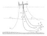
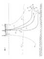
- FIG. 1is perspective view of a production facility providing electrical power to subsea equipment with an umbilical made in accordance with the present invention.
- FIG. 2is sectional view of the umbilical of FIG. 1 taken along line 2 - 2 .
- a structure 11is shown at the surface of the sea.
- Structure 11is typically moored to a sea floor 13 by a plurality of mooring lines 15 .
- structure 11is shown as a platform, it will be readily appreciated by those skilled in the art that structure 11 can alternatively be a floating production storage and offloading (FPSO) vessel.
- FPSOfloating production storage and offloading
- sea floor 13is greater than or equal to 1500 feet deep such that structure 11 is supporting deepwater operations.
- sea floor 13is greater than or equal to 4000 feet deep such that structure 11 is supporting ultra-deepwater operations.
- “deepwater” and “ultra-deepwater”are terms of art which can vary slightly depending upon those you talk with and time. For the purposes of this invention, it is contemplated that these terms shall be as listed above.
- a production riser 17communicates hydrocarbons produced from a plurality of wellheads 19 to structure 11 .
- Risers 17can receive hydrocarbons directly from a one of wellheads 19 , or alternatively receive hydrocarbons from another subsea collection structure 21 such as a collection manifold or a subsea pump which is in fluid communication with riser 17 .
- a power umbilical 23extends from structure 11 toward sea floor 13 to provide electrical power to the subsea equipment.
- power umbilicalcan also be used for communication and control purposes by including additional lines within power umbilical.
- power umbilicalregisters with a distribution module 25 .
- Distribution module 25receives the electrical power from power umbilical and distributes it to the other subsea equipment, such as wellheads 19 and collection structure 21 , via lines 27 .
- distribution module 25could distribute power to a variety of subsea electrical equipment that are not illustrated but are contemplated as part of the present invention. Many such subsea equipment are listed above here in the Background of the Invention.
- umbilical 23in an embodiment of the invention includes an outer jacket 29 and an armor package 31 that sealingly protects the internal components of umbilical 2 from the sea water as well as providing a first layer of protection from structural damage, for example resulting from impacts, friction, and bending during deployment.
- An inner liner or belt 33is carried within jacket 29 and armor package 31 .
- Belt 33provides further protection for the internal components of umbilical 23 , as well as defining an inner or effective diameter of umbilical 23 .
- belt 33carries a tubular lubricant conduit 37 and a communication conduit 39 .
- Communication conduit 39preferably carries communications means such as fiber optic lines.
- Lubricant conduit 37 callprovide lubrication fluid to the subsea equipment. Alternatively, or additionally if there are a plurality of lubricant conduits as shown in FIG. 2 , lubricant conduit 37 can provide hydraulic fluid for use in actuating hydraulically controlled subsea and downhole mechanisms.
- Belt 33can also carries carbon fiber rods 41 intermittently spaced therein to increase the longitudinal strength of umbilical 23 , while decreasing the in-water weight as compared to prior umbilicals relying solely upon belt 33 , armor package 31 , and jacket 29 for such strength.
- Umbilical 23includes a power cable 43 that is also carried within belt 33 .
- such power cables 43are symmetrically spaced within belt 33 , with lubricant conduit 37 , communication conduit 39 , and carbon fiber rods 41 embedded in the interstitial spaces or interspatial locations therebetween, as best illustrated in FIG. 2 .
- power cables 43include a conductor 45 .
- Conductor 45can be a cable or line having an acceptable conductance.
- copper and aluminumboth have conductive properties that are desirable for conveying electrical current.
- conductor 45is a stranded conductor having a plurality of small conductor lines or cables that are bunched or grouped together.
- conductor 45when conductor 45 is a stranded conductor with a plurality of copper cables, it is contemplated that conductor 45 will be about one-half inch in diameter. With conductor 45 having a one-half inch diameter, umbilical 23 having the components illustrated in FIG.
- conductor 45comprises a stranded conductor having lines that are copper.
- other conductive metalsmay be utilized as well.
- Such alternate conductorsmay increase the diameter of conductor 45 . While in some situations it may not be desirable to increase the size of umbilical 23 by increasing the size of conductor 45 when using Aluminum (typically doubling in diameter), such an arrangement can decrease the overall weight of umbilical because Aluminum weighs less.
- Some such alternate conductors, such as aluminumwould not experience creep or deformation like copper conductors; however, the increase in diameter to achieve the necessary communication of electrical power may not be beneficial at this time.
- a strength or support conduit member 47surrounds each conductor 45 .
- support member or conduit 47is close-coupled with conductor 45 so that support member 47 carries the weight associated with each conductor 45 .
- conductor 45can be held in place relative to an interior surface of support member 47 by frictional forces due solely from an interference-fit relationship associated with the close coupling.
- support member 47may have a textured inner surface 48 to increase frictional forces such that the close coupling of support member 47 does not need to create as much of an interference fit.
- support member 47comprises metal tubing that is seam welded and swaged around conductor 45 .
- support member 47hermetically seals conductor 45 and therefore prevents the problem of hydrogen migration along conductor 45 as discussed above herein.
- support member 47can comprise a plurality of metal members held together by a nonmetallic substrate, similar to an armor package.
- support member 47should have either non-magnetic or low magnetic properties based upon their material compositions, such as stainless steel.
- magnetic propertiesare typically associated with the presence of iron carbite (Fe3C) in a material. It is preferred if no iron carbite is present, such that support member 47 is non-metallic. However, in the manufacturing processes associated with support member 47 , even stainless steel, a small amount of iron carbite may form. Such formations can be acceptable so long as such formations create only low magnetic properties for support member 47 .
- Such low magnetic propertiesare preferably such that there is not a significant disruption of the waveforms associated with the electrical current due to any electromagnetic interference caused by magnetic elements in close proximity to conductor 45 .
- Examples of acceptable non- or low magnetic property stainless steelsinclude “duplex” stainless steel as well as AL 4565 Alloy stainless steel.
- Duplex stainless steelstypically have a mixed microstructure of austenite and ferrite. Typically, during production, the manufacturer aims at producing a 50:50 mix of austenite and ferrite. However, in commercial alloys the mix may be 40:60 respectively.
- Duplex stainless steelsare often characterized by high chromium (19-32 wt. %) and molybdenum (up to 5 wt. %) and lower nickel contents than austenitic stainless steels.
- AL 4565 alloy stainless steels(UNS S34565) are “superaustenitic stainless steels” which typically have high strength and toughness.
- AL 4565 alloy stainless steelshave a typical material composition of 23-25 wt. % chromium, 5-7 wt. % Manganese, 4-5 wt. % Molybdenum, 0.4-0.6 wt. % Nitrogen, 16-18 wt. % Nickel, less than or equal to 0.01 wt. % Carbon, and the remainder being Iron.
- the magnetic properties of a stainless steeltypically decrease as the chromium content increase, whereas a 32 wt. % chromium has substantially no magnetic properties.
- a high allow stainless steel having a chromium content of 19-32 wt. %is acceptable (such as with the AL 4565 stainless steel), as well as 22-25 wt. % with the Duplex stainless steels.
- it would also be acceptable to use other such high allow stainless steelssuch as “Super Duplex” stainless steel, which has at least 25 wt. % chromium.
- power cable 43also includes an insulator 49 that surrounds and encloses both conductor 45 and strength member 47 .
- Strength member 47 and insulator 49act together to help to transfer heat from the conductive lines within conductor 45 , as well providing additional protection against sea water.
- Positioning support member 47 between insulator 49 and conductor 45is contemplated as helping to accomplish the reduction in the size of the support member 47 as well as allowing support member to carry the weight of conductor 45 .
- Having support member 47 carry the weight of conductor 45helps to reduce and/or eliminate the creep or deformation associated with the conductor 45 over a predetermined lifetime of the hydrocarbon producing field (typically twenty (20) years) because the conductor lines are no longer supporting themselves.
- umbilical 23allows structure 11 to provide electrical power to subsea equipment when sea floor 13 is greater than or equal to 1500 feet deep such that structure 11 is supporting deepwater operations. In another embodiment of this invention, umbilical 23 allows structure 11 to provide electrical power to subsea equipment when sea floor 13 is greater than or equal to 4000 feet deep such that structure 11 is supporting ultra-deepwater operations. In yet another embodiment, umbilical 23 allows structure 11 to provide electrical power to subsea equipment when sea floor 13 is greater than or equal to 10,000 feet deep.
- support member 47when support member 47 is a tubular metal conduit that is welded and swaged around conductor 45 conductor 45 is hermetically sealed to prevent the problem of hydrogen migration along conductor 45 as discussed above herein. In each of these embodiments, the weight of conductor 45 is transferred and carried by support member 47 , which helps to reduce and eliminate creep for metal conductors such as copper.
- umbilical 23is illustrated as a being catenary type, but may also be vertical or an S-type curve due to buoys (e.g. a “Lazy Wave”).
- the number of power cables 43can be altered according to specific design requirements.
- support members 47can comprise other materials having non-magnetic or low magnetic properties than those specifically provided as examples.
Landscapes
- Engineering & Computer Science (AREA)
- Ocean & Marine Engineering (AREA)
- Insulated Conductors (AREA)
Abstract
Description
Claims (24)
Priority Applications (4)
| Application Number | Priority Date | Filing Date | Title |
|---|---|---|---|
| US11/939,212US9299480B2 (en) | 2007-11-13 | 2007-11-13 | Subsea power umbilical |
| EP08849246AEP2210260A4 (en) | 2007-11-13 | 2008-10-09 | Subsea power umbilical |
| BRPI0819441BRPI0819441A2 (en) | 2007-11-13 | 2008-10-09 | Umbilical set for subsea power supply, subsea power supply system, and method of supplying power from a sea surface structure to subsea power supply |
| PCT/US2008/079276WO2009064559A1 (en) | 2007-11-13 | 2008-10-09 | Subsea power umbilical |
Applications Claiming Priority (1)
| Application Number | Priority Date | Filing Date | Title |
|---|---|---|---|
| US11/939,212US9299480B2 (en) | 2007-11-13 | 2007-11-13 | Subsea power umbilical |
Publications (2)
| Publication Number | Publication Date |
|---|---|
| US20090120632A1 US20090120632A1 (en) | 2009-05-14 |
| US9299480B2true US9299480B2 (en) | 2016-03-29 |
Family
ID=40622620
Family Applications (1)
| Application Number | Title | Priority Date | Filing Date |
|---|---|---|---|
| US11/939,212Expired - Fee RelatedUS9299480B2 (en) | 2007-11-13 | 2007-11-13 | Subsea power umbilical |
Country Status (4)
| Country | Link |
|---|---|
| US (1) | US9299480B2 (en) |
| EP (1) | EP2210260A4 (en) |
| BR (1) | BRPI0819441A2 (en) |
| WO (1) | WO2009064559A1 (en) |
Families Citing this family (15)
| Publication number | Priority date | Publication date | Assignee | Title |
|---|---|---|---|---|
| GB2474428B (en) | 2009-10-13 | 2012-03-21 | Technip France | Umbilical |
| MX2012011719A (en)* | 2010-04-08 | 2013-03-20 | Framo Eng As | System and method for subsea power distribution network. |
| GB2479725B (en)* | 2010-04-19 | 2012-08-22 | Technip France | Umbilical |
| AU2010361698B2 (en) | 2010-09-30 | 2016-03-17 | Technip France | Subsea umbilical |
| US8517634B1 (en)* | 2011-03-30 | 2013-08-27 | Chevron U.S.A. Inc. | Systems and methods for replacing, repositioning and repairing a section of subsea pipe located on a seabed |
| EP2697801B8 (en) | 2011-04-12 | 2016-05-11 | Ticona LLC | Composite core for electrical transmission cables |
| JP2014515868A (en) | 2011-04-12 | 2014-07-03 | ティコナ・エルエルシー | Submarine cables for use in submarine applications |
| TWI549140B (en) | 2011-04-12 | 2016-09-11 | 堤康那責任有限公司 | Thermoplastic rod reinforced with continuous fiber |
| US8950497B2 (en)* | 2012-04-23 | 2015-02-10 | Chevron U.S.A. Inc. | Assemblies, systems and methods for installing multiple subsea functional lines |
| NO339731B1 (en)* | 2013-09-12 | 2017-01-23 | Aker Solutions As | Power umbilical with FO cable |
| WO2016062681A1 (en)* | 2014-10-23 | 2016-04-28 | Sandvik Intellectual Property Ab | Umbilical tube and umbilical |
| GB2552693B (en)* | 2016-08-04 | 2019-11-27 | Technip France | Umbilical end termination |
| US10683711B2 (en)* | 2017-01-19 | 2020-06-16 | Baker Hughes, A Ge Company, Llc | Frictional enhancement of mating surfaces of power cable installed in coiled tubing |
| WO2018231972A1 (en)* | 2017-06-15 | 2018-12-20 | Shell Oil Company | Mineral insulated power and control cables for subsea applications |
| EP4163932A1 (en) | 2021-10-11 | 2023-04-12 | Nexans | Hvac-cable with composite conductor |
Citations (38)
| Publication number | Priority date | Publication date | Assignee | Title |
|---|---|---|---|---|
| US3212582A (en)* | 1959-02-09 | 1965-10-19 | Kenard D Brown | Plastic drill pipes and sucker rods for oil wells |
| US4196307A (en)* | 1977-06-07 | 1980-04-01 | Custom Cable Company | Marine umbilical cable |
| DE3012321A1 (en) | 1979-06-20 | 1981-01-29 | Huber & Suhner Ag | TWO OR MULTIPLE CABLE |
| US4476923A (en)* | 1980-07-21 | 1984-10-16 | Walling John B | Flexible tubing production system for well installation |
| US4556340A (en)* | 1983-08-15 | 1985-12-03 | Conoco Inc. | Method and apparatus for production of subsea hydrocarbons using a floating vessel |
| US4821804A (en)* | 1985-03-27 | 1989-04-18 | Pierce Robert H | Composite support column assembly for offshore drilling and production platforms |
| US4952012A (en)* | 1988-11-17 | 1990-08-28 | Stamnitz Timothy C | Electro-opto-mechanical cable for fiber optic transmission systems |
| US5042903A (en)* | 1990-07-30 | 1991-08-27 | Westinghouse Electric Corp. | High voltage tow cable with optical fiber |
| US5506818A (en)* | 1992-10-15 | 1996-04-09 | I/O Exploration Products (U.S.A.), Inc. | Seismic source system utilizing a small diameter hose bundle |
| US5667649A (en) | 1995-06-29 | 1997-09-16 | Bushman; James B. | Corrosion-resistant ferrous alloys for use as impressed current anodes |
| GB2326177A (en)* | 1997-04-29 | 1998-12-16 | Kvaerner Oilfield Prod As | Dynamic umbilical with load bearing core member |
| GB2326758A (en)* | 1997-04-29 | 1998-12-30 | Kvaerner Oilfield Prod As | Weighted subsea control cable |
| US5902958A (en)* | 1996-04-26 | 1999-05-11 | Norsk Subsea Cable As | Arrangement in a cable |
| US5908049A (en)* | 1990-03-15 | 1999-06-01 | Fiber Spar And Tube Corporation | Spoolable composite tubular member with energy conductors |
| US5921285A (en)* | 1995-09-28 | 1999-07-13 | Fiberspar Spoolable Products, Inc. | Composite spoolable tube |
| US6012495A (en)* | 1996-09-05 | 2000-01-11 | Alcatel | Corrosion protection for subsea lines |
| US6239363B1 (en)* | 1995-09-29 | 2001-05-29 | Marine Innovations, L.L.C. | Variable buoyancy cable |
| US6283206B1 (en)* | 1999-07-01 | 2001-09-04 | Kellogg, Brown & Root, Inc. | Gas lift umbilical cable and termination assemblies therefor |
| US6355879B1 (en)* | 1999-09-07 | 2002-03-12 | Utilx Corporation | Flow-through cable |
| US6397948B1 (en) | 1998-11-03 | 2002-06-04 | Fmc Technologies, Inc. | Shearing arrangement for subsea umbilicals |
| US6472614B1 (en)* | 2000-01-07 | 2002-10-29 | Coflexip | Dynamic umbilicals with internal steel rods |
| US6538198B1 (en)* | 2000-05-24 | 2003-03-25 | Timothy M. Wooters | Marine umbilical |
| US20030094281A1 (en) | 2000-06-29 | 2003-05-22 | Tubel Paulo S. | Method and system for monitoring smart structures utilizing distributed optical sensors |
| US6612370B1 (en)* | 1998-04-16 | 2003-09-02 | Kvaerner Oilfield Products As | Composite hybrid riser |
| US6638198B1 (en)* | 1997-04-28 | 2003-10-28 | Michael J. Shea | Exercise system |
| US6940054B1 (en)* | 1999-08-20 | 2005-09-06 | Kvaerner Oilfield Products As | Production/injection line and methods relating to same |
| US6943300B2 (en)* | 2003-08-13 | 2005-09-13 | Nexans | Flexible electrical elongated device suitable for service in a high mechanical load environment |
| US6973244B2 (en) | 2003-05-06 | 2005-12-06 | Nexans | Cable with crevice corrosion protection |
| US6978825B1 (en)* | 1998-12-31 | 2005-12-27 | Bouygues Offshore | Device and process for the heat insulation of at least one underwater pipe at great depth |
| WO2005124095A1 (en)* | 2004-06-18 | 2005-12-29 | Aker Kvaerner Subsea As | Umbilical |
| US20060113110A1 (en) | 2000-12-18 | 2006-06-01 | Impact Engineering Solutions Limited | Drilling system and method |
| US20060175063A1 (en) | 2004-12-20 | 2006-08-10 | Balkanyi Szabolcs R | Method and apparatus for a cold flow subsea hydrocarbon production system |
| US7158803B1 (en)* | 2003-09-16 | 2007-01-02 | Verizon Corporate Services Group Inc. | Emergency services for wireless data access networks |
| US7158703B2 (en)* | 2005-02-11 | 2007-01-02 | Nexans | Power umbilical for deep water |
| US20070044992A1 (en) | 2005-08-25 | 2007-03-01 | Bremnes Jarle J | Subsea power cable |
| US20070251694A1 (en)* | 2005-11-18 | 2007-11-01 | Gwo-Tarng Ju | Umbilical assembly, subsea system, and methods of use |
| US7686073B1 (en)* | 2006-11-10 | 2010-03-30 | Angel Petroleum Technologies, LLC | Tubing string |
| US7753111B1 (en)* | 2007-11-02 | 2010-07-13 | Angel Petroleum Technologies LLC | Reinforced tubing string |
Family Cites Families (1)
| Publication number | Priority date | Publication date | Assignee | Title |
|---|---|---|---|---|
| CN2845111Y (en)* | 2005-03-28 | 2006-12-06 | 湘潭市特种线缆厂 | Super flexible controlling cable against radiation |
- 2007
- 2007-11-13USUS11/939,212patent/US9299480B2/ennot_activeExpired - Fee Related
- 2008
- 2008-10-09BRBRPI0819441patent/BRPI0819441A2/ennot_activeIP Right Cessation
- 2008-10-09EPEP08849246Apatent/EP2210260A4/ennot_activeWithdrawn
- 2008-10-09WOPCT/US2008/079276patent/WO2009064559A1/enactiveApplication Filing
Patent Citations (44)
| Publication number | Priority date | Publication date | Assignee | Title |
|---|---|---|---|---|
| US3212582A (en)* | 1959-02-09 | 1965-10-19 | Kenard D Brown | Plastic drill pipes and sucker rods for oil wells |
| US4196307A (en)* | 1977-06-07 | 1980-04-01 | Custom Cable Company | Marine umbilical cable |
| DE3012321A1 (en) | 1979-06-20 | 1981-01-29 | Huber & Suhner Ag | TWO OR MULTIPLE CABLE |
| US4476923A (en)* | 1980-07-21 | 1984-10-16 | Walling John B | Flexible tubing production system for well installation |
| US4556340A (en)* | 1983-08-15 | 1985-12-03 | Conoco Inc. | Method and apparatus for production of subsea hydrocarbons using a floating vessel |
| US4821804A (en)* | 1985-03-27 | 1989-04-18 | Pierce Robert H | Composite support column assembly for offshore drilling and production platforms |
| US4952012A (en)* | 1988-11-17 | 1990-08-28 | Stamnitz Timothy C | Electro-opto-mechanical cable for fiber optic transmission systems |
| US5908049A (en)* | 1990-03-15 | 1999-06-01 | Fiber Spar And Tube Corporation | Spoolable composite tubular member with energy conductors |
| US5913337A (en)* | 1990-03-15 | 1999-06-22 | Fiber Spar And Ture Corporation | Spoolable composite tubular member with energy conductors |
| US5042903A (en)* | 1990-07-30 | 1991-08-27 | Westinghouse Electric Corp. | High voltage tow cable with optical fiber |
| US5506818A (en)* | 1992-10-15 | 1996-04-09 | I/O Exploration Products (U.S.A.), Inc. | Seismic source system utilizing a small diameter hose bundle |
| US5667649A (en) | 1995-06-29 | 1997-09-16 | Bushman; James B. | Corrosion-resistant ferrous alloys for use as impressed current anodes |
| US5921285A (en)* | 1995-09-28 | 1999-07-13 | Fiberspar Spoolable Products, Inc. | Composite spoolable tube |
| US6239363B1 (en)* | 1995-09-29 | 2001-05-29 | Marine Innovations, L.L.C. | Variable buoyancy cable |
| US5902958A (en)* | 1996-04-26 | 1999-05-11 | Norsk Subsea Cable As | Arrangement in a cable |
| US6012495A (en)* | 1996-09-05 | 2000-01-11 | Alcatel | Corrosion protection for subsea lines |
| US6638198B1 (en)* | 1997-04-28 | 2003-10-28 | Michael J. Shea | Exercise system |
| GB2326758A (en)* | 1997-04-29 | 1998-12-30 | Kvaerner Oilfield Prod As | Weighted subsea control cable |
| GB2326177A (en)* | 1997-04-29 | 1998-12-16 | Kvaerner Oilfield Prod As | Dynamic umbilical with load bearing core member |
| US6046404A (en)* | 1997-04-29 | 2000-04-04 | Kvaerner Oilfield Products A.S. | Subsea control cable |
| US6146052A (en)* | 1997-04-29 | 2000-11-14 | Kvaerner Oilfield Products A.S | Dynamic control cable for use between a floating structure and a connection point on the seabed |
| US6612370B1 (en)* | 1998-04-16 | 2003-09-02 | Kvaerner Oilfield Products As | Composite hybrid riser |
| US6397948B1 (en) | 1998-11-03 | 2002-06-04 | Fmc Technologies, Inc. | Shearing arrangement for subsea umbilicals |
| US6978825B1 (en)* | 1998-12-31 | 2005-12-27 | Bouygues Offshore | Device and process for the heat insulation of at least one underwater pipe at great depth |
| US6283206B1 (en)* | 1999-07-01 | 2001-09-04 | Kellogg, Brown & Root, Inc. | Gas lift umbilical cable and termination assemblies therefor |
| US6940054B1 (en)* | 1999-08-20 | 2005-09-06 | Kvaerner Oilfield Products As | Production/injection line and methods relating to same |
| US6355879B1 (en)* | 1999-09-07 | 2002-03-12 | Utilx Corporation | Flow-through cable |
| US6472614B1 (en)* | 2000-01-07 | 2002-10-29 | Coflexip | Dynamic umbilicals with internal steel rods |
| US6538198B1 (en)* | 2000-05-24 | 2003-03-25 | Timothy M. Wooters | Marine umbilical |
| US20030094281A1 (en) | 2000-06-29 | 2003-05-22 | Tubel Paulo S. | Method and system for monitoring smart structures utilizing distributed optical sensors |
| US6913079B2 (en)* | 2000-06-29 | 2005-07-05 | Paulo S. Tubel | Method and system for monitoring smart structures utilizing distributed optical sensors |
| US20060113110A1 (en) | 2000-12-18 | 2006-06-01 | Impact Engineering Solutions Limited | Drilling system and method |
| US6973244B2 (en) | 2003-05-06 | 2005-12-06 | Nexans | Cable with crevice corrosion protection |
| US6943300B2 (en)* | 2003-08-13 | 2005-09-13 | Nexans | Flexible electrical elongated device suitable for service in a high mechanical load environment |
| US7158803B1 (en)* | 2003-09-16 | 2007-01-02 | Verizon Corporate Services Group Inc. | Emergency services for wireless data access networks |
| WO2005124095A1 (en)* | 2004-06-18 | 2005-12-29 | Aker Kvaerner Subsea As | Umbilical |
| US20070205009A1 (en)* | 2004-06-18 | 2007-09-06 | Arild Figenschou | Umbilical |
| US20070253778A1 (en)* | 2004-06-18 | 2007-11-01 | Aker Kvaerner Subsea As | Power Umbilical Compromising Separate Load Carrying Elements Of Composite Material |
| US20060175063A1 (en) | 2004-12-20 | 2006-08-10 | Balkanyi Szabolcs R | Method and apparatus for a cold flow subsea hydrocarbon production system |
| US7158703B2 (en)* | 2005-02-11 | 2007-01-02 | Nexans | Power umbilical for deep water |
| US20070044992A1 (en) | 2005-08-25 | 2007-03-01 | Bremnes Jarle J | Subsea power cable |
| US20070251694A1 (en)* | 2005-11-18 | 2007-11-01 | Gwo-Tarng Ju | Umbilical assembly, subsea system, and methods of use |
| US7686073B1 (en)* | 2006-11-10 | 2010-03-30 | Angel Petroleum Technologies, LLC | Tubing string |
| US7753111B1 (en)* | 2007-11-02 | 2010-07-13 | Angel Petroleum Technologies LLC | Reinforced tubing string |
Non-Patent Citations (3)
| Title |
|---|
| PCT International Search Report and Written Opinion, International App. No. PCT/US 08/79276, Dec. 12, 2008. |
| PCT International Search Report and Written Opinion, International App. No. PCT/US 2008/079276, dated May 27, 2010. |
| Supplementary European Search Report regarding European Patent Application No. 08849246.7 dated Jan. 15, 2013 (2 pages). |
Also Published As
| Publication number | Publication date |
|---|---|
| EP2210260A4 (en) | 2013-02-13 |
| WO2009064559A1 (en) | 2009-05-22 |
| EP2210260A1 (en) | 2010-07-28 |
| US20090120632A1 (en) | 2009-05-14 |
| BRPI0819441A2 (en) | 2015-05-05 |
Similar Documents
| Publication | Publication Date | Title |
|---|---|---|
| US9299480B2 (en) | Subsea power umbilical | |
| US6538198B1 (en) | Marine umbilical | |
| US8186911B2 (en) | Power umbilical comprising separate load carrying elements of composite material | |
| EP2818024B1 (en) | Long step out direct electric heating assembly | |
| US20110240312A1 (en) | Permanent cable for submersible pumps in oil well applications | |
| US20180231150A1 (en) | Unbonded flexible pipe | |
| GB2552693B (en) | Umbilical end termination | |
| US8783358B2 (en) | Methods and systems for circulating fluid within the annulus of a flexible pipe riser | |
| US20050054228A1 (en) | Mid-line connector and method for pipe-in-pipe electrical heating | |
| GB2326177A (en) | Dynamic umbilical with load bearing core member | |
| CN110546305B (en) | Arrangement of electrical continuity and/or radial support | |
| US7493918B2 (en) | Fluid conduit | |
| NO20130076A1 (en) | Pipe-enclosed motor cable | |
| US20120247782A1 (en) | Marine riser adjustable buoyancy modules | |
| AU2009275328B2 (en) | Umbilical | |
| CN101075731B (en) | An electric power supply system and a method of production thereof | |
| EP3161366A1 (en) | An offshore pipe system and a method of heating unbonded flexible pipes in an offshore pipe system | |
| EA025400B1 (en) | Method of well intervention | |
| EP3060791B1 (en) | Electrical power generation | |
| AU2007259101B2 (en) | A method of securing wires of at least one armour layer and inner and outer collar members of a portion of flexible pipe | |
| US10024482B2 (en) | Bend stiffener assembly | |
| WO2022079183A1 (en) | Submarine cable comprising at least one aluminium tensile reinforcement strand, related umbilical, installation and method | |
| WO1994010492A1 (en) | Improved offshore umbilical and method of forming an offshore umbilical | |
| US11127512B2 (en) | Cable for downhole tractor deployment | |
| EP3057107B1 (en) | Coiled tubing power cable for deep wells |
Legal Events
| Date | Code | Title | Description |
|---|---|---|---|
| AS | Assignment | Owner name:TANJU, BAHA TULU, TEXAS Free format text:ASSIGNMENT OF ASSIGNORS INTEREST;ASSIGNOR:CHEVRON U.S.A, INC.;REEL/FRAME:020103/0557 Effective date:20071113 Owner name:WORMAN, PETER J., TEXAS Free format text:ASSIGNMENT OF ASSIGNORS INTEREST;ASSIGNOR:CHEVRON U.S.A, INC.;REEL/FRAME:020103/0557 Effective date:20071113 | |
| AS | Assignment | Owner name:CHEVRON U.S.A. INC., CALIFORNIA Free format text:CORRECTIVE ASSIGNMENT TO CORRECT THE RECEIVING PARTY FROM WORMAN, PETER J., TANJU, BAHA TULU TO CHEVRON U.S.A. INC. PREVIOUSLY RECORDED ON REEL 020103 FRAME 0557. ASSIGNOR(S) HEREBY CONFIRMS THE SELL, ASSIGNMENT, TRANSFER AND SET OVER UNTO SAID CHEVRON U.S.A. INC;ASSIGNORS:TANJU, BAHA TULU;WORMAN, PETER J.;REEL/FRAME:030020/0465 Effective date:20071113 | |
| STCF | Information on status: patent grant | Free format text:PATENTED CASE | |
| FEPP | Fee payment procedure | Free format text:MAINTENANCE FEE REMINDER MAILED (ORIGINAL EVENT CODE: REM.); ENTITY STATUS OF PATENT OWNER: LARGE ENTITY | |
| LAPS | Lapse for failure to pay maintenance fees | Free format text:PATENT EXPIRED FOR FAILURE TO PAY MAINTENANCE FEES (ORIGINAL EVENT CODE: EXP.); ENTITY STATUS OF PATENT OWNER: LARGE ENTITY | |
| STCH | Information on status: patent discontinuation | Free format text:PATENT EXPIRED DUE TO NONPAYMENT OF MAINTENANCE FEES UNDER 37 CFR 1.362 | |
| FP | Expired due to failure to pay maintenance fee | Effective date:20200329 |