US9298230B2 - Electronic device - Google Patents
Electronic deviceDownload PDFInfo
- Publication number
- US9298230B2 US9298230B2US14/474,862US201414474862AUS9298230B2US 9298230 B2US9298230 B2US 9298230B2US 201414474862 AUS201414474862 AUS 201414474862AUS 9298230 B2US9298230 B2US 9298230B2
- Authority
- US
- United States
- Prior art keywords
- plate
- dividing
- electronic device
- spaces
- rear plate
- Prior art date
- Legal status (The legal status is an assumption and is not a legal conclusion. Google has not performed a legal analysis and makes no representation as to the accuracy of the status listed.)
- Active, expires
Links
Images


Classifications
- G—PHYSICS
- G06—COMPUTING OR CALCULATING; COUNTING
- G06F—ELECTRIC DIGITAL DATA PROCESSING
- G06F1/00—Details not covered by groups G06F3/00 - G06F13/00 and G06F21/00
- G06F1/16—Constructional details or arrangements
- G06F1/20—Cooling means
- G—PHYSICS
- G06—COMPUTING OR CALCULATING; COUNTING
- G06F—ELECTRIC DIGITAL DATA PROCESSING
- G06F1/00—Details not covered by groups G06F3/00 - G06F13/00 and G06F21/00
- G06F1/16—Constructional details or arrangements
- G06F1/18—Packaging or power distribution
- G06F1/183—Internal mounting support structures, e.g. for printed circuit boards, internal connecting means
- G06F1/187—Mounting of fixed and removable disk drives
- H—ELECTRICITY
- H05—ELECTRIC TECHNIQUES NOT OTHERWISE PROVIDED FOR
- H05K—PRINTED CIRCUITS; CASINGS OR CONSTRUCTIONAL DETAILS OF ELECTRIC APPARATUS; MANUFACTURE OF ASSEMBLAGES OF ELECTRICAL COMPONENTS
- H05K7/00—Constructional details common to different types of electric apparatus
- H05K7/20—Modifications to facilitate cooling, ventilating, or heating
- H05K7/20709—Modifications to facilitate cooling, ventilating, or heating for server racks or cabinets; for data centers, e.g. 19-inch computer racks
- H05K7/20718—Forced ventilation of a gaseous coolant
- H05K7/20736—Forced ventilation of a gaseous coolant within cabinets for removing heat from server blades
Definitions
- the subject matter hereingenerally relates to an electronic device.
- Electronic modulessuch as hard disks are installed in an electronic device, such as a server or a computer.
- the electronic modules in the electronic deviceare orderly arranged in rows.
- fans and air ventsare used for cooling the electronic modules.
- FIG. 1is an exploded, isometric view of an embodiment of an electronic device.
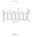
- FIG. 2is a diagrammatic view of an airflow path of a first embodiment of an electronic device.
- FIG. 3is a diagrammatic view of an airflow path of a second embodiment of an electronic device.
- FIG. 4is a diagrammatic view of an airflow path of a third embodiment of an electronic device.
- the present disclosureis described in relation to an electronic device.
- FIGS. 1 and 2illustrate a first embodiment of an electronic device.
- the electronic deviceincludes a chassis 100 and a plurality of electronic modules 50 .
- the chassis 100includes a front plate 101 , a rear plate 103 , a top plate 104 , two side plates 105 , a bottom plate 107 and a plurality of dividing plates 30 .
- the dividing plates 30are parallel to and located between the front plate 101 and the rear plate 103 , and perpendicularly connected to the two side plates 105 .
- a space 108is defined between a bottom of each dividing plate 30 and the bottom plate 107 .
- a space 109is defined between a top of each dividing plate 30 and the top plate 104 .
- An airflow path 301is defined between each two adjacent dividing plates 30 .
- Each electronic module 50is vertically set between two adjacent dividing plates 30 .
- the dividing plates 30are arranged stepped down from the front plate 101 to the rear plate 103 .
- the space 109orderly increases from the front plate 101 to the rear plate 103 .
- the space 108orderly decreases from the front plate 101 to the rear plate 103 .
- a bottom of the front plate 101defines an air inlet 102 .
- the electronic modules 50are hard disk drive modules.
- FIG. 3illustrates a second embodiment of an electronic device.
- the bottoms of the dividing plates 30are arranged stepped down from the front plate 101 to the rear plate 103 .
- the spaces 109 between each top of the dividing plates 30 and the top plate 104are equal.
- the spaces 108orderly decrease from the front plate 101 to the rear plate 103 .
- FIG. 4illustrates a third embodiment of an electronic device, the tops of the dividing plates 30 are arranged stepped down from the front plate 101 to the rear plate 103 .
- the spaces 108 between each bottom of the dividing plates 30 and the bottom plate 107are equal.
- the spaces 109orderly increase from the front plate 101 to the rear plate 103 .
- FIGS. 2 to 4illustrate that an air flow such as cooling air flows through the air inlet 102 , the space 108 , and upwardly through the electronic modules 50 , and then flows out from the space 109 .
- the chassis 100includes a fan adjacent to the rear plate 103 to extract the airflow out from the chassis 100 .
- the dividing plates 30circumvent preheated air from the electronic modules 50 at the front of the chassis 100 from flowing to the electronic modules 50 at the rear of the chassis 100 .
- the declined arrangement of the bottoms of the dividing plates 30can allow for increased airflow, through the electronic modules 50 adjacent to the rear plate 103 .
- the declined arrangement of the tops of the dividing plates 30can improve the airflow flow out of the electronic modules 50 increasing the cooling effect of the electronic device.
Landscapes
- Engineering & Computer Science (AREA)
- Theoretical Computer Science (AREA)
- Physics & Mathematics (AREA)
- General Engineering & Computer Science (AREA)
- Human Computer Interaction (AREA)
- General Physics & Mathematics (AREA)
- Computer Hardware Design (AREA)
- Thermal Sciences (AREA)
- Microelectronics & Electronic Packaging (AREA)
- Power Engineering (AREA)
- Cooling Or The Like Of Electrical Apparatus (AREA)
Abstract
Description
Claims (6)
Applications Claiming Priority (3)
| Application Number | Priority Date | Filing Date | Title |
|---|---|---|---|
| TW102132080 | 2013-09-05 | ||
| TW102132080ATW201511656A (en) | 2013-09-05 | 2013-09-05 | Electronic device |
| TW102132080U | 2013-09-05 |
Publications (2)
| Publication Number | Publication Date |
|---|---|
| US20150062799A1 US20150062799A1 (en) | 2015-03-05 |
| US9298230B2true US9298230B2 (en) | 2016-03-29 |
Family
ID=52582939
Family Applications (1)
| Application Number | Title | Priority Date | Filing Date |
|---|---|---|---|
| US14/474,862Active2034-09-08US9298230B2 (en) | 2013-09-05 | 2014-09-02 | Electronic device |
Country Status (2)
| Country | Link |
|---|---|
| US (1) | US9298230B2 (en) |
| TW (1) | TW201511656A (en) |
Cited By (11)
| Publication number | Priority date | Publication date | Assignee | Title |
|---|---|---|---|---|
| US9968005B2 (en)* | 2016-03-08 | 2018-05-08 | Quanta Computer, Inc. | Different HDD gap architecture to reduce upstream preheat for high-density storage |
| US20180299932A1 (en)* | 2017-04-17 | 2018-10-18 | EMC IP Holding Company LLC | Chassis and heat sink for use in chassis |
| US20190090374A1 (en)* | 2017-09-18 | 2019-03-21 | Facebook, Inc. | Apparatus, system, and method for partitioning a storage-system chassis |
| US10429911B2 (en) | 2017-09-07 | 2019-10-01 | Facebook, Inc. | Apparatus, system, and method for detecting device types of storage devices |
| US10537035B2 (en) | 2017-09-06 | 2020-01-14 | Facebook, Inc. | Apparatus, system, and method for securing hard drives in a storage chassis |
| US10558248B2 (en) | 2017-09-09 | 2020-02-11 | Facebook, Inc. | Apparatus, system, and method for indicating the status of and securing hard drives |
| US10687435B2 (en) | 2017-08-28 | 2020-06-16 | Facebook, Inc. | Apparatus, system, and method for enabling multiple storage-system configurations |
| US10736228B2 (en) | 2017-08-31 | 2020-08-04 | Facebook, Inc. | Removeable drive-plane apparatus, system, and method |
| US10757831B2 (en) | 2017-09-26 | 2020-08-25 | Facebook, Inc. | Apparatus, system, and method for reconfiguring air flow through a chassis |
| US11347674B2 (en)* | 2011-03-22 | 2022-05-31 | Amazon Technologies, Inc. | Modular mass storage system |
| US11553626B2 (en)* | 2014-03-17 | 2023-01-10 | Amazon Technologies, Inc. | Discrete cooling module |
Families Citing this family (4)
| Publication number | Priority date | Publication date | Assignee | Title |
|---|---|---|---|---|
| US9474190B1 (en)* | 2014-08-14 | 2016-10-18 | Amazon Technologies, Inc. | Computer system with side plenum cooling |
| US10631440B1 (en)* | 2016-05-26 | 2020-04-21 | Amazon Technologies, Inc. | Server chassis with composite wall |
| CN108227849B (en) | 2016-12-21 | 2021-07-06 | 伊姆西Ip控股有限责任公司 | Roof arrangements for storage facilities and corresponding storage facilities |
| US10412859B1 (en)* | 2017-07-21 | 2019-09-10 | EMC IP Holding Company LLC | Storage device carrier system |
Citations (6)
| Publication number | Priority date | Publication date | Assignee | Title |
|---|---|---|---|---|
| US6563704B2 (en)* | 2001-06-15 | 2003-05-13 | Sun Microsystems, Inc. | Storage device arrangement for increased cooling |
| US20050052843A1 (en)* | 2003-09-10 | 2005-03-10 | Baker David A. | Chassis cooling system |
| US20080298014A1 (en)* | 2007-05-29 | 2008-12-04 | Michael John Franco | Modular electronic enclosure |
| US8238104B2 (en)* | 2010-08-09 | 2012-08-07 | Amazon Technologies, Inc. | Data center with fin modules |
| US8743549B2 (en)* | 2011-03-22 | 2014-06-03 | Amazon Technologies, Inc. | Modular mass storage system |
| US9141156B2 (en)* | 2013-08-02 | 2015-09-22 | Amazon Technologies, Inc. | Compute node cooling with air fed through backplane |
- 2013
- 2013-09-05TWTW102132080Apatent/TW201511656A/enunknown
- 2014
- 2014-09-02USUS14/474,862patent/US9298230B2/enactiveActive
Patent Citations (6)
| Publication number | Priority date | Publication date | Assignee | Title |
|---|---|---|---|---|
| US6563704B2 (en)* | 2001-06-15 | 2003-05-13 | Sun Microsystems, Inc. | Storage device arrangement for increased cooling |
| US20050052843A1 (en)* | 2003-09-10 | 2005-03-10 | Baker David A. | Chassis cooling system |
| US20080298014A1 (en)* | 2007-05-29 | 2008-12-04 | Michael John Franco | Modular electronic enclosure |
| US8238104B2 (en)* | 2010-08-09 | 2012-08-07 | Amazon Technologies, Inc. | Data center with fin modules |
| US8743549B2 (en)* | 2011-03-22 | 2014-06-03 | Amazon Technologies, Inc. | Modular mass storage system |
| US9141156B2 (en)* | 2013-08-02 | 2015-09-22 | Amazon Technologies, Inc. | Compute node cooling with air fed through backplane |
Cited By (17)
| Publication number | Priority date | Publication date | Assignee | Title |
|---|---|---|---|---|
| US12124394B2 (en) | 2011-03-22 | 2024-10-22 | Amazon Technologies, Inc. | Modular mass storage system |
| US11347674B2 (en)* | 2011-03-22 | 2022-05-31 | Amazon Technologies, Inc. | Modular mass storage system |
| US11553626B2 (en)* | 2014-03-17 | 2023-01-10 | Amazon Technologies, Inc. | Discrete cooling module |
| US9968005B2 (en)* | 2016-03-08 | 2018-05-08 | Quanta Computer, Inc. | Different HDD gap architecture to reduce upstream preheat for high-density storage |
| CN108733175B (en)* | 2017-04-17 | 2021-05-07 | 伊姆西Ip控股有限责任公司 | Frame and heat dissipation device for same |
| US10672430B2 (en)* | 2017-04-17 | 2020-06-02 | EMC IP Holding Company LLC | Chassis and heat sink for use in chassis |
| CN108733175A (en)* | 2017-04-17 | 2018-11-02 | 伊姆西Ip控股有限责任公司 | Rack and radiator for rack |
| US20180299932A1 (en)* | 2017-04-17 | 2018-10-18 | EMC IP Holding Company LLC | Chassis and heat sink for use in chassis |
| US10687435B2 (en) | 2017-08-28 | 2020-06-16 | Facebook, Inc. | Apparatus, system, and method for enabling multiple storage-system configurations |
| US11032934B1 (en) | 2017-08-28 | 2021-06-08 | Facebook, Inc. | Apparatus, system, and method for enabling multiple storage-system configurations |
| US10736228B2 (en) | 2017-08-31 | 2020-08-04 | Facebook, Inc. | Removeable drive-plane apparatus, system, and method |
| US10537035B2 (en) | 2017-09-06 | 2020-01-14 | Facebook, Inc. | Apparatus, system, and method for securing hard drives in a storage chassis |
| US10429911B2 (en) | 2017-09-07 | 2019-10-01 | Facebook, Inc. | Apparatus, system, and method for detecting device types of storage devices |
| US10558248B2 (en) | 2017-09-09 | 2020-02-11 | Facebook, Inc. | Apparatus, system, and method for indicating the status of and securing hard drives |
| US10588238B2 (en)* | 2017-09-18 | 2020-03-10 | Facebook, Inc. | Apparatus, system, and method for partitioning a storage-system chassis |
| US20190090374A1 (en)* | 2017-09-18 | 2019-03-21 | Facebook, Inc. | Apparatus, system, and method for partitioning a storage-system chassis |
| US10757831B2 (en) | 2017-09-26 | 2020-08-25 | Facebook, Inc. | Apparatus, system, and method for reconfiguring air flow through a chassis |
Also Published As
| Publication number | Publication date |
|---|---|
| TW201511656A (en) | 2015-03-16 |
| US20150062799A1 (en) | 2015-03-05 |
Similar Documents
| Publication | Publication Date | Title |
|---|---|---|
| US9298230B2 (en) | Electronic device | |
| JP5651521B2 (en) | Computer cabinet having a gradual air velocity cooling system and associated method of manufacture and use | |
| US8300409B2 (en) | Fan duct for electronic components of electronic device | |
| US20120276834A1 (en) | Container data center having high heat dissipation efficiency | |
| US10028416B2 (en) | Heat dissipating system for data center | |
| US20130312940A1 (en) | Heat dissipating device and system | |
| US20130141865A1 (en) | Heat dissipation system | |
| US20170112023A1 (en) | Cooling system for data center | |
| US20140036433A1 (en) | Airflow guiding member and electronic device having the airflow guiding member | |
| US20140036439A1 (en) | Electronic device | |
| US20170294069A1 (en) | Temperature-controlled vending machine | |
| US20120134103A1 (en) | Server cabinet for server system | |
| US20150163959A1 (en) | Electronic device with fan module | |
| US20140111939A1 (en) | Electronic device with heat dissipation module | |
| US20160224077A1 (en) | Enclosure of electronic device | |
| US8934236B2 (en) | Server cabinet | |
| CN104765432A (en) | Server combination | |
| US10251315B1 (en) | Apparatuses and methods for cooling high density arrays of non-volatile memory mass storage devices | |
| CN104423512A (en) | Electronic device | |
| US20110236194A1 (en) | Fan apparatus with air duct | |
| US20150146363A1 (en) | Server | |
| CN206312035U (en) | A kind of No. eight rack-mount servers | |
| CN104423506A (en) | Electronic device | |
| US20140363315A1 (en) | Electronic device and air blower | |
| US20120108157A1 (en) | Container data center |
Legal Events
| Date | Code | Title | Description |
|---|---|---|---|
| AS | Assignment | Owner name:HON HAI PRECISION INDUSTRY CO., LTD., TAIWAN Free format text:ASSIGNMENT OF ASSIGNORS INTEREST;ASSIGNOR:WEI, CHAO-KE;REEL/FRAME:033651/0647 Effective date:20140731 | |
| STCF | Information on status: patent grant | Free format text:PATENTED CASE | |
| AS | Assignment | Owner name:CLOUD NETWORK TECHNOLOGY SINGAPORE PTE. LTD., SINGAPORE Free format text:ASSIGNMENT OF ASSIGNORS INTEREST;ASSIGNOR:HON HAI PRECISION INDUSTRY CO., LTD.;REEL/FRAME:045281/0269 Effective date:20180112 Owner name:CLOUD NETWORK TECHNOLOGY SINGAPORE PTE. LTD., SING Free format text:ASSIGNMENT OF ASSIGNORS INTEREST;ASSIGNOR:HON HAI PRECISION INDUSTRY CO., LTD.;REEL/FRAME:045281/0269 Effective date:20180112 | |
| MAFP | Maintenance fee payment | Free format text:PAYMENT OF MAINTENANCE FEE, 4TH YEAR, LARGE ENTITY (ORIGINAL EVENT CODE: M1551); ENTITY STATUS OF PATENT OWNER: LARGE ENTITY Year of fee payment:4 | |
| MAFP | Maintenance fee payment | Free format text:PAYMENT OF MAINTENANCE FEE, 8TH YEAR, LARGE ENTITY (ORIGINAL EVENT CODE: M1552); ENTITY STATUS OF PATENT OWNER: LARGE ENTITY Year of fee payment:8 |