US9298002B2 - Optical configurations for head worn computing - Google Patents
Optical configurations for head worn computingDownload PDFInfo
- Publication number
- US9298002B2 US9298002B2US14/543,751US201414543751AUS9298002B2US 9298002 B2US9298002 B2US 9298002B2US 201414543751 AUS201414543751 AUS 201414543751AUS 9298002 B2US9298002 B2US 9298002B2
- Authority
- US
- United States
- Prior art keywords
- light
- eye
- head
- image light
- image
- Prior art date
- Legal status (The legal status is an assumption and is not a legal conclusion. Google has not performed a legal analysis and makes no representation as to the accuracy of the status listed.)
- Active
Links
- 230000003287optical effectEffects0.000titleclaimsabstractdescription130
- 238000005286illuminationMethods0.000claimsdescription30
- 238000003384imaging methodMethods0.000claimsdescription25
- 239000007787solidSubstances0.000claimsdescription22
- 239000003086colorantSubstances0.000claimsdescription5
- 238000012163sequencing techniqueMethods0.000claims1
- KRUDZWOELKQDJW-UHFFFAOYSA-N3-amino-5-bromo-1-methylpyridin-2-oneChemical compoundCN1C=C(Br)C=C(N)C1=OKRUDZWOELKQDJW-UHFFFAOYSA-N0.000description47
- 230000000694effectsEffects0.000description30
- 230000010287polarizationEffects0.000description25
- 239000011521glassSubstances0.000description17
- 239000002096quantum dotSubstances0.000description14
- 210000003128headAnatomy0.000description13
- 238000000034methodMethods0.000description13
- 230000008859changeEffects0.000description8
- 238000000576coating methodMethods0.000description6
- 230000007613environmental effectEffects0.000description6
- 239000000463materialSubstances0.000description6
- 230000008569processEffects0.000description6
- 239000011248coating agentSubstances0.000description5
- 238000013461designMethods0.000description5
- 230000004297night visionEffects0.000description5
- 230000008901benefitEffects0.000description4
- 230000005540biological transmissionEffects0.000description4
- 230000001419dependent effectEffects0.000description4
- 238000007726management methodMethods0.000description4
- 239000011358absorbing materialSubstances0.000description3
- 239000006059cover glassSubstances0.000description3
- 238000005516engineering processMethods0.000description3
- 230000002093peripheral effectEffects0.000description3
- 238000010521absorption reactionMethods0.000description2
- NIXOWILDQLNWCW-UHFFFAOYSA-Nacrylic acid groupChemical groupC(C=C)(=O)ONIXOWILDQLNWCW-UHFFFAOYSA-N0.000description2
- 239000000853adhesiveSubstances0.000description2
- 230000001070adhesive effectEffects0.000description2
- 230000003190augmentative effectEffects0.000description2
- 238000004891communicationMethods0.000description2
- 230000004438eyesightEffects0.000description2
- 230000006870functionEffects0.000description2
- 238000012423maintenanceMethods0.000description2
- 230000007246mechanismEffects0.000description2
- 230000000116mitigating effectEffects0.000description2
- 230000001629suppressionEffects0.000description2
- 239000002699waste materialSubstances0.000description2
- 238000002835absorbanceMethods0.000description1
- 229910052782aluminiumInorganic materials0.000description1
- XAGFODPZIPBFFR-UHFFFAOYSA-NaluminiumChemical compound[Al]XAGFODPZIPBFFR-UHFFFAOYSA-N0.000description1
- 238000000149argon plasma sinteringMethods0.000description1
- 238000012790confirmationMethods0.000description1
- 230000007423decreaseEffects0.000description1
- 230000000593degrading effectEffects0.000description1
- 238000001514detection methodMethods0.000description1
- 230000004424eye movementEffects0.000description1
- 210000000887faceAnatomy0.000description1
- 238000004519manufacturing processMethods0.000description1
- 238000005259measurementMethods0.000description1
- 229910052751metalInorganic materials0.000description1
- 239000002184metalSubstances0.000description1
- 239000003973paintSubstances0.000description1
- 230000000737periodic effectEffects0.000description1
- 230000002085persistent effectEffects0.000description1
- 238000000103photoluminescence spectrumMethods0.000description1
- 229920000515polycarbonatePolymers0.000description1
- 239000004417polycarbonateSubstances0.000description1
- 238000012545processingMethods0.000description1
- 238000002310reflectometryMethods0.000description1
- 230000008439repair processEffects0.000description1
- 230000004044responseEffects0.000description1
- 210000001525retinaAnatomy0.000description1
- 239000005336safety glassSubstances0.000description1
- 230000003595spectral effectEffects0.000description1
- 239000000126substanceSubstances0.000description1
- 239000000758substrateSubstances0.000description1
- 230000001360synchronised effectEffects0.000description1
- 238000002834transmittanceMethods0.000description1
- 238000002211ultraviolet spectrumMethods0.000description1
- 238000001429visible spectrumMethods0.000description1
- 230000000007visual effectEffects0.000description1
Images


Classifications
- G—PHYSICS
- G02—OPTICS
- G02B—OPTICAL ELEMENTS, SYSTEMS OR APPARATUS
- G02B26/00—Optical devices or arrangements for the control of light using movable or deformable optical elements
- G02B26/08—Optical devices or arrangements for the control of light using movable or deformable optical elements for controlling the direction of light
- G02B26/0816—Optical devices or arrangements for the control of light using movable or deformable optical elements for controlling the direction of light by means of one or more reflecting elements
- G02B26/0833—Optical devices or arrangements for the control of light using movable or deformable optical elements for controlling the direction of light by means of one or more reflecting elements the reflecting element being a micromechanical device, e.g. a MEMS mirror, DMD
- G—PHYSICS
- G02—OPTICS
- G02B—OPTICAL ELEMENTS, SYSTEMS OR APPARATUS
- G02B27/00—Optical systems or apparatus not provided for by any of the groups G02B1/00 - G02B26/00, G02B30/00
- G02B27/01—Head-up displays
- G02B27/017—Head mounted
- G02B27/0172—Head mounted characterised by optical features
- G—PHYSICS
- G02—OPTICS
- G02B—OPTICAL ELEMENTS, SYSTEMS OR APPARATUS
- G02B27/00—Optical systems or apparatus not provided for by any of the groups G02B1/00 - G02B26/00, G02B30/00
- G02B27/0093—Optical systems or apparatus not provided for by any of the groups G02B1/00 - G02B26/00, G02B30/00 with means for monitoring data relating to the user, e.g. head-tracking, eye-tracking
- G—PHYSICS
- G02—OPTICS
- G02B—OPTICAL ELEMENTS, SYSTEMS OR APPARATUS
- G02B27/00—Optical systems or apparatus not provided for by any of the groups G02B1/00 - G02B26/00, G02B30/00
- G02B27/01—Head-up displays
- G02B27/0101—Head-up displays characterised by optical features
- G—PHYSICS
- G02—OPTICS
- G02B—OPTICAL ELEMENTS, SYSTEMS OR APPARATUS
- G02B5/00—Optical elements other than lenses
- G02B5/30—Polarising elements
- G—PHYSICS
- G02—OPTICS
- G02B—OPTICAL ELEMENTS, SYSTEMS OR APPARATUS
- G02B27/00—Optical systems or apparatus not provided for by any of the groups G02B1/00 - G02B26/00, G02B30/00
- G02B27/01—Head-up displays
- G02B27/0101—Head-up displays characterised by optical features
- G02B2027/0118—Head-up displays characterised by optical features comprising devices for improving the contrast of the display / brillance control visibility
- G—PHYSICS
- G02—OPTICS
- G02B—OPTICAL ELEMENTS, SYSTEMS OR APPARATUS
- G02B27/00—Optical systems or apparatus not provided for by any of the groups G02B1/00 - G02B26/00, G02B30/00
- G02B27/01—Head-up displays
- G02B27/0101—Head-up displays characterised by optical features
- G02B2027/0138—Head-up displays characterised by optical features comprising image capture systems, e.g. camera
- G—PHYSICS
- G02—OPTICS
- G02B—OPTICAL ELEMENTS, SYSTEMS OR APPARATUS
- G02B27/00—Optical systems or apparatus not provided for by any of the groups G02B1/00 - G02B26/00, G02B30/00
- G02B27/01—Head-up displays
- G02B27/0101—Head-up displays characterised by optical features
- G02B2027/014—Head-up displays characterised by optical features comprising information/image processing systems
- G—PHYSICS
- G02—OPTICS
- G02B—OPTICAL ELEMENTS, SYSTEMS OR APPARATUS
- G02B27/00—Optical systems or apparatus not provided for by any of the groups G02B1/00 - G02B26/00, G02B30/00
- G02B27/01—Head-up displays
- G02B27/017—Head mounted
- G02B27/0172—Head mounted characterised by optical features
- G02B2027/0174—Head mounted characterised by optical features holographic
- G—PHYSICS
- G02—OPTICS
- G02B—OPTICAL ELEMENTS, SYSTEMS OR APPARATUS
- G02B27/00—Optical systems or apparatus not provided for by any of the groups G02B1/00 - G02B26/00, G02B30/00
- G02B27/01—Head-up displays
- G02B27/017—Head mounted
- G02B2027/0178—Eyeglass type
Definitions
- This inventionrelates to head worn computing. More particularly, this invention relates to optical systems used in head worn computing.
- aspects of the present inventionrelate to optical systems in head worn computing. Aspects relate to the management of “off” pixel light. Aspects relate to absorbing “off” pixel light. Aspects relate to improved see-through transparency of the HWC optical path to the surrounding environment. Aspects relate to improved image contrast, brightness, sharpness and other image quality through the management of stray light. Aspects relate to eye imaging through “off” pixels. Aspects relate to security compliance and security compliance tracking through eye imaging. Aspects relate to guest access of a HWC through eye imaging. Aspects relate to providing system and software access based on eye imaging.
- FIG. 1illustrates a head worn computing system in accordance with the principles of the present invention.
- FIG. 2illustrates a head worn computing system with optical system in accordance with the principles of the present invention.
- FIG. 3 aillustrates a large prior art optical arrangement.
- FIG. 3 billustrates an upper optical module in accordance with the principles of the present invention.
- FIG. 4illustrates an upper optical module in accordance with the principles of the present invention.
- FIG. 4 aillustrates an upper optical module in accordance with the principles of the present invention.
- FIG. 4 billustrates an upper optical module in accordance with the principles of the present invention.
- FIG. 5illustrates an upper optical module in accordance with the principles of the present invention.
- FIG. 5 aillustrates an upper optical module in accordance with the principles of the present invention.
- FIG. 5 billustrates an upper optical module and dark light trap according to the principles of the present invention.
- FIG. 5 cillustrates an upper optical module and dark light trap according to the principles of the present invention.
- FIG. 5 dillustrates an upper optical module and dark light trap according to the principles of the present invention.
- FIG. 5 eillustrates an upper optical module and dark light trap according to the principles of the present invention.
- FIG. 6illustrates upper and lower optical modules in accordance with the principles of the present invention.
- FIG. 7illustrates angles of combiner elements in accordance with the principles of the present invention.
- FIG. 8illustrates upper and lower optical modules in accordance with the principles of the present invention.
- FIG. 8 aillustrates upper and lower optical modules in accordance with the principles of the present invention.
- FIG. 8 billustrates upper and lower optical modules in accordance with the principles of the present invention.
- FIG. 8 cillustrates upper and lower optical modules in accordance with the principles of the present invention.
- FIG. 9illustrates an eye imaging system in accordance with the principles of the present invention.
- FIG. 10illustrates a light source in accordance with the principles of the present invention.
- FIG. 10 aillustrates a back lighting system in accordance with the principles of the present invention.
- FIG. 10 billustrates a back lighting system in accordance with the principles of the present invention.
- FIG. 11 a to 11 dillustrate a light source and filter in accordance with the principles of the present invention.
- FIG. 12 a to 12 cillustrate a light source and quantum dot system in accordance with the principles of the present invention.
- FIG. 13 aillustrates optical components of a lower optical module together with an outer lens.
- FIG. 13 billustrates a cross section of the embodiment described in FIG. 13 a.
- FIG. 13 cillustrates an embodiment where the combiner element is angled away from the eye at the top and towards the eye at the bottom.
- FIG. 14 aillustrates a removable and replaceable flexible eye cover with an opening that can be attached and removed quickly from the through the use of magnets.
- FIG. 14 billustrates a removable and replaceable flexible eye cover that is adapted as a single eye cover.
- FIG. 14 cillustrates an embodiment of a light suppression system.
- HWChead-worn computing
- the glassesmay be a fully developed computing platform, such as including computer displays presented in each of the lenses of the glasses to the eyes of the user.
- the lenses and displaysmay be configured to allow a person wearing the glasses to see the environment through the lenses while also seeing, simultaneously, digital imagery, which forms an overlaid image that is perceived by the person as a digitally augmented image of the environment, or augmented reality (“AR”).
- ARaugmented reality
- HWCinvolves more than just placing a computing system on a person's head.
- the systemmay need to be designed as a lightweight, compact and fully functional computer display, such as wherein the computer display includes a high resolution digital display that provides a high level of emersion comprised of the displayed digital content and the see-through view of the environmental surroundings.
- User interfaces and control systems suited to the HWC devicemay be required that are unlike those used for a more conventional computer such as a laptop.
- the glassesmay be equipped with sensors to determine environmental conditions, geographic location, relative positioning to other points of interest, objects identified by imaging and movement by the user or other users in a connected group, and the like.
- the HWCmay then change the mode of operation to match the conditions, location, positioning, movements, and the like, in a method generally referred to as a contextually aware HWC.
- the glassesalso may need to be connected, wirelessly or otherwise, to other systems either locally or through a network. Controlling the glasses may be achieved through the use of an external device, automatically through contextually gathered information, through user gestures captured by the glasses sensors, and the like. Each technique may be further refined depending on the software application being used in the glasses.
- the glassesmay further be used to control or coordinate with external devices that are associated with the glasses.
- the HWC system 100comprises a HWC 102 , which in this instance is configured as glasses to be worn on the head with sensors such that the HWC 102 is aware of the objects and conditions in the environment 114 .
- the HWC 102also receives and interprets control inputs such as gestures and movements 116 .
- the HWC 102may communicate with external user interfaces 104 .
- the external user interfaces 104may provide a physical user interface to take control instructions from a user of the HWC 102 and the external user interfaces 104 and the HWC 102 may communicate bi-directionally to affect the user's command and provide feedback to the external device 108 .
- the HWC 102may also communicate bi-directionally with externally controlled or coordinated local devices 108 .
- an external user interface 104may be used in connection with the HWC 102 to control an externally controlled or coordinated local device 108 .
- the externally controlled or coordinated local device 108may provide feedback to the HWC 102 and a customized GUI may be presented in the HWC 102 based on the type of device or specifically identified device 108 .
- the HWC 102may also interact with remote devices and information sources 112 through a network connection 110 .
- the external user interface 104may be used in connection with the HWC 102 to control or otherwise interact with any of the remote devices 108 and information sources 112 in a similar way as when the external user interfaces 104 are used to control or otherwise interact with the externally controlled or coordinated local devices 108 .
- HWC 102may interpret gestures 116 (e.g captured from forward, downward, upward, rearward facing sensors such as camera(s), range finders, IR sensors, etc.) or environmental conditions sensed in the environment 114 to control either local or remote devices 108 or 112 .
- the HWC 102is a computing platform intended to be worn on a person's head.
- the HWC 102may take many different forms to fit many different functional requirements.
- the HWC 102will be designed in the form of conventional glasses.
- the glassesmay or may not have active computer graphics displays.
- the displaysmay be configured as see-through displays such that the digital imagery can be overlaid with respect to the user's view of the environment 114 .
- see-through optical designsincluding ones that have a reflective display (e.g. LCoS, DLP), emissive displays (e.g. OLED, LED), hologram, TIR waveguides, and the like.
- lighting systems used in connection with the display opticsmay be solid state lighting systems, such as LED, OLED, quantum dot, quantum dot LED, etc.
- the optical configurationmay be monocular or binocular. It may also include vision corrective optical components.
- the opticsmay be packaged as contact lenses.
- the HWC 102may be in the form of a helmet with a see-through shield, sunglasses, safety glasses, goggles, a mask, fire helmet with see-through shield, police helmet with see through shield, military helmet with see-through shield, utility form customized to a certain work task (e.g. inventory control, logistics, repair, maintenance, etc.), and the like.
- the HWC 102may also have a number of integrated computing facilities, such as an integrated processor, integrated power management, communication structures (e.g. cell net, WiFi, Bluetooth, local area connections, mesh connections, remote connections (e.g. client server, etc.)), and the like.
- the HWC 102may also have a number of positional awareness sensors, such as GPS, electronic compass, altimeter, tilt sensor, IMU, and the like. It may also have other sensors such as a camera, rangefinder, hyper-spectral camera, Geiger counter, microphone, spectral illumination detector, temperature sensor, chemical sensor, biologic sensor, moisture sensor, ultrasonic sensor, and the like.
- the HWC 102may also have integrated control technologies.
- the integrated control technologiesmay be contextual based control, passive control, active control, user control, and the like.
- the HWC 102may have an integrated sensor (e.g. camera) that captures user hand or body gestures 116 such that the integrated processing system can interpret the gestures and generate control commands for the HWC 102 .
- the HWC 102may have sensors that detect movement (e.g. a nod, head shake, and the like) including accelerometers, gyros and other inertial measurements, where the integrated processor may interpret the movement and generate a control command in response.
- the HWC 102may also automatically control itself based on measured or perceived environmental conditions.
- the HWC 102may increase the brightness or contrast of the displayed image.
- the integrated control technologiesmay be mounted on the HWC 102 such that a user can interact with it directly.
- the HWC 102may have a button(s), touch capacitive interface, and the like.
- the HWC 102may be in communication with external user interfaces 104 .
- the external user interfacesmay come in many different forms.
- a cell phone screenmay be adapted to take user input for control of an aspect of the HWC 102 .
- the external user interfacemay be a dedicated UI, such as a keyboard, touch surface, button(s), joy stick, and the like.
- the external controllermay be integrated into another device such as a ring, watch, bike, car, and the like.
- the external user interface 104may include sensors (e.g. IMU, accelerometers, compass, altimeter, and the like) to provide additional input for controlling the HWD 104 .
- sensorse.g. IMU, accelerometers, compass, altimeter, and the like
- the HWC 102may control or coordinate with other local devices 108 .
- the external devices 108may be an audio device, visual device, vehicle, cell phone, computer, and the like.
- the local external device 108may be another HWC 102 , where information may then be exchanged between the separate HWCs 108 .
- the HWC 102may control or coordinate with remote devices 112 , such as the HWC 102 communicating with the remote devices 112 through a network 110 .
- the form of the remote device 112may have many forms. Included in these forms is another HWC 102 .
- each HWC 102may communicate its GPS position such that all the HWCs 102 know where all of HWC 102 are located.
- FIG. 2illustrates a HWC 102 with an optical system that includes an upper optical module 202 and a lower optical module 204 .
- the upper and lower optical modules 202 and 204will generally be described as separate modules, it should be understood that this is illustrative only and the present invention includes other physical configurations, such as that when the two modules are combined into a single module or where the elements making up the two modules are configured into more than two modules.
- the upper module 202includes a computer controlled display (e.g. LCoS, DLP, OLED, etc.) and image light delivery optics.
- the lower moduleincludes eye delivery optics that are configured to receive the upper module's image light and deliver the image light to the eye of a wearer of the HWC.
- FIG. 1illustrates a HWC 102 with an optical system that includes an upper optical module 202 and a lower optical module 204 .
- the upper and lower optical modules 202 and 204will generally be described as separate modules, it should be understood that this is illustrative
- FIG. 3 billustrates an upper optical module 202 in accordance with the principles of the present invention.
- the upper optical module 202includes a DLP (also known as DMD or digital micromirror device) computer operated display 304 which includes pixels comprised of rotatable mirrors (such as, for example, the DLP3000 available from Texas Instruments), polarized light source 302 , 1 ⁇ 4 wave retarder film 308 , reflective polarizer 310 and a field lens 312 .
- the polarized light source 302provides substantially uniform polarized light that is generally directed towards the reflective polarizer 310 .
- the reflective polarizerreflects light of one polarization state (e.g.
- the polarized light source 302 and the reflective polarizer 310are oriented so that the polarized light from the polarized light source 302 is reflected generally towards the DLP 304 .
- the lightthen passes through the 1 ⁇ 4wave film 308 once before illuminating the pixels of the DLP 304 and then again after being reflected by the pixels of the DLP 304 .
- the lightis converted from one polarization state to the other polarization state (e.g. the light is converted from S to P polarized light).
- the lightthen passes through the reflective polarizer 310 .
- the DLP pixel(s)are in the “on” state (i.e. the mirrors are positioned to reflect light towards the field lens 312 , the “on” pixels reflect the light generally along the optical axis and into the field lens 312 .
- This light that is reflected by “on” pixels and which is directed generally along the optical axis of the field lens 312will be referred to as image light 316 .
- the image light 316then passes through the field lens to be used by a lower optical module 204 .
- the light that is provided by the polarized light source 302 , which is subsequently reflected by the reflective polarizer 310 before it reflects from the DLP 304 ,will generally be referred to as illumination light.
- the light that is reflected by the “off” pixels of the DLP 304is reflected at a different angle than the light reflected by the ‘on” pixels, so that the light from the “off” pixels is generally directed away from the optical axis of the field lens 312 and toward the side of the upper optical module 202 as shown in FIG. 3 .
- the light that is reflected by the “off” pixels of the DLP 304will be referred to as dark state light 314 .
- the DLP 304operates as a computer controlled display and is generally thought of as a MEMs device.
- the DLP pixelsare comprised of small mirrors that can be directed. The mirrors generally flip from one angle to another angle. The two angles are generally referred to as states. When light is used to illuminate the DLP the mirrors will reflect the light in a direction depending on the state. In embodiments herein, we generally refer to the two states as “on” and “off,” which is intended to depict the condition of a display pixel. “On” pixels will be seen by a viewer of the display as emitting light because the light is directed along the optical axis and into the field lens and the associated remainder of the display system.
- “Off” pixelswill be seen by a viewer of the display as not emitting light because the light from these pixels is directed to the side of the optical housing and into a light trap or light dump where the light is absorbed.
- the pattern of “on” and “off” pixelsproduces image light that is perceived by a viewer of the display as a computer generated image.
- Full color imagescan be presented to a user by sequentially providing illumination light with complimentary colors such as red, green and blue. Where the sequence is presented in a recurring cycle that is faster than the user can perceive as separate images and as a result the user perceives a full color image comprised of the sum of the sequential images.
- Bright pixels in the imageare provided by pixels that remain in the “on” state for the entire time of the cycle, while dimmer pixels in the image are provided by pixels that switch between the “on” state and “off” state within the time of the cycle, or frame time when in a video sequence of images.
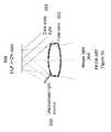
- FIG. 3 ashows an illustration of a system for a DLP 304 in which the unpolarized light source 350 is pointed directly at the DLP 304 .
- the angle required for the illumination lightis such that the field lens 352 must be positioned substantially distant from the DLP 304 to avoid the illumination light from being clipped by the field lens 352 .
- the large distance between the field lens 352 and the DLP 304 along with the straight path of the dark state light 354means that the light trap for the dark state light 354 is also located at a substantial distance from the DLP. For these reasons, this configuration is larger in size compared to the upper optics module 202 of the preferred embodiments.
- the configuration illustrated in FIG. 3 bcan be lightweight and compact such that it fits into a small portion of a HWC.
- the upper modules 202 illustrated hereincan be physically adapted to mount in an upper frame of a HWC such that the image light can be directed into a lower optical module 204 for presentation of digital content to a wearer's eye.
- the package of components that combine to generate the image lighti.e. the polarized light source 302 , DLP 304 , reflective polarizer 310 and 1 ⁇ 4 wave film 308 ) is very light and is compact.
- the height of the system, excluding the field lensmay be less than 8 mm.
- the width (i.e. from front to back)may be less than 8 mm.
- the weightmay be less than 2 grams.
- the compactness of this upper optical module 202allows for a compact mechanical design of the HWC and the light weight nature of these embodiments help make the HWC lightweight to provide for a HWC that is comfortable for a wearer of the HWC.
- the configuration illustrated in FIG. 3 bcan produce sharp contrast, high brightness and deep blacks, especially when compared to LCD or LCoS displays used in HWC.
- the “on” and “off” states of the DLPprovide for a strong differentiator in the light reflection path representing an “on” pixel and an “off” pixel.
- the dark state light from the “off” pixel reflectionscan be managed to reduce stray light in the display system to produce images with high contrast.
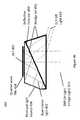
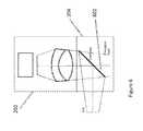
- FIG. 4illustrates another embodiment of an upper optical module 202 in accordance with the principles of the present invention.
- This embodimentincludes a light source 404 , but in this case, the light source can provide unpolarized illumination light.
- the illumination light from the light source 404is directed into a TIR wedge 418 such that the illumination light is incident on an internal surface of the TIR wedge 418 (shown as the angled lower surface of the TRI wedge 418 in FIG. 4 ) at an angle that is beyond the critical angle as defined by Eqn 1.
- Critical anglearc ⁇ sin(1/ n )
- Eqn 1secasin(1/ n )
- illumination lightis turned toward the DLP 402 at an angle suitable for providing image light 414 as reflected from “on” pixels.
- the illumination lightis provided to the DLP 402 at approximately twice the angle of the pixel mirrors in the DLP 402 that are in the “on” state, such that after reflecting from the pixel mirrors, the image light 414 is directed generally along the optical axis of the field lens.
- the illumination light from “on” pixelsmay be reflected as image light 414 which is directed towards a field lens and a lower optical module 204 , while illumination light reflected from “off” pixels (generally referred to herein as “dark” state light, “off” pixel light or “off” state light) 410 is directed in a separate direction, which may be trapped and not used for the image that is ultimately presented to the wearer's eye.
- the light trap for the dark state light 410may be located along the optical axis defined by the direction of the dark state light 410 and in the side of the housing, with the function of absorbing the dark state light.
- the light trapmay be comprised of an area outside of the cone of image light 414 from the “on” pixels.
- the light trapis typically made up of materials that absorb light including coatings of black paints or other light absorbing materials to prevent light scattering from the dark state light degrading the image perceived by the user.
- the light trapmay be recessed into the wall of the housing or include masks or guards to block scattered light and prevent the light trap from being viewed adjacent to the displayed image.
- the embodiment of FIG. 4also includes a corrective wedge 420 to correct the effect of refraction of the image light 414 as it exits the TIR wedge 418 .
- a corrective wedge 420to correct the effect of refraction of the image light 414 as it exits the TIR wedge 418 .
- the image light from the “on” pixelscan be maintained generally in a direction along the optical axis of the field lens (i.e. the same direction as that defined by the image light 414 ) so it passes into the field lens and the lower optical module 204 .
- the image light 414 from the “on” pixelsexits the corrective wedge 420 generally perpendicular to the surface of the corrective wedge 420 while the dark state light exits at an oblique angle.
- the direction of the image light 414 from the “on” pixelsis largely unaffected by refraction as it exits from the surface of the corrective wedge 420 .
- the dark state light 410is substantially changed in direction by refraction when the dark state light 410 exits the corrective wedge 420 .
- the embodiment illustrated in FIG. 4has the similar advantages of those discussed in connection with the embodiment of FIG. 3 b .
- the dimensions and weight of the upper module 202 depicted in FIG. 4may be approximately 8 ⁇ 8 mm with a weight of less than 3 grams.
- a difference in overall performance between the configuration illustrated in FIG. 3 b and the configuration illustrated in FIG. 4is that the embodiment of FIG. 4 doesn't require the use of polarized light as supplied by the light source 404 . This can be an advantage in some situations as will be discussed in more detail below (e.g. increased see-through transparency of the HWC optics from the user's perspective). Polarized light may be used in connection with the embodiment depicted in FIG. 4 , in embodiments.
- the dark state light(shown as DLP off light 410 ) is directed at a steeper angle away from the optical axis of the image light 414 due to the added refraction encountered when the dark state light 410 exits the corrective wedge 420 .
- This steeper angle of the dark state light 410allows for the light trap to be positioned closer to the DLP 402 so that the overall size of the upper module 202 can be reduced.
- the light trapcan also be made larger since the light trap doesn't interfere with the field lens, thereby the efficiency of the light trap can be increased and as a result, stray light can be reduced and the contrast of the image perceived by the user can be increased.
- FIG. 4 aillustrates the embodiment described in connection with FIG. 4 with an example set of corresponding angles at the various surfaces with the reflected angles of a ray of light passing through the upper optical module 202 .
- the DLP mirrorsare provided at 17 degrees to the surface of the DLP device.
- the angles of the TIR wedgeare selected in correspondence to one another to provide TIR reflected illumination light at the correct angle for the DLP mirrors while allowing the image light and dark state light to pass through the thin air gap, various combinations of angles are possible to achieve this.
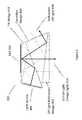
- FIG. 5illustrates yet another embodiment of an upper optical module 202 in accordance with the principles of the present invention.
- the embodiment shown in FIG. 5does not require the use of polarized light. Polarized light may be used in connection with this embodiment, but it is not required.
- the optical module 202 depicted in FIG. 5is similar to that presented in connection with FIG. 4 ; however, the embodiment of FIG. 5 includes an off light redirection wedge 502 . As can be seen from the illustration, the off light redirection wedge 502 allows the image light 414 to continue generally along the optical axis toward the field lens and into the lower optical module 204 (as illustrated).
- the off light 504is redirected substantially toward the side of the corrective wedge 420 where it passes into the light trap.
- This configurationmay allow further height compactness in the HWC because the light trap (not illustrated) that is intended to absorb the off light 504 can be positioned laterally adjacent the upper optical module 202 as opposed to below it.
- the light trap(not illustrated) that is intended to absorb the off light 504 can be positioned laterally adjacent the upper optical module 202 as opposed to below it.
- there is a thin air gap between the TIR wedge 418 and the corrective wedge 420similar to the embodiment of FIG. 4 .
- There is also a thin air gap between the corrective wedge 420 and the off light redirection wedge 502There may be HWC mechanical configurations that warrant the positioning of a light trap for the dark state light elsewhere and the illustration depicted in FIG.
- FIG. 5should be considered illustrative of the concept that the off light can be redirected to create compactness of the overall HWC.
- FIG. 5 aillustrates an example of the embodiment described in connection with FIG. 5 with the addition of more details on the relative angles at the various surfaces and a light ray trace for image light and a light ray trace for dark light are shown as it passes through the upper optical module 202 . Again, various combinations of angles are possible.
- FIG. 4 bshows an illustration of a further embodiment in which a solid transparent matched set of wedges 456 is provided with a reflective polarizer 450 at the interface between the wedges.
- the interface between the wedges in the wedge set 456is provided at an angle so that illumination light 452 from the polarized light source 458 is reflected at the proper angle (e.g. 34 degrees for a 17 degree DLP mirror) for the DLP mirror “on” state so that the reflected image light 414 is provided along the optical axis of the field lens.
- the general geometry of the wedges in the wedge set 456is similar to that shown in FIGS. 4 and 4 a .
- a quarter wave film 454is provided on the DLP 402 surface so that the illumination light 452 is one polarization state (e.g. S polarization state) while in passing through the quarter wave film 454 , reflecting from the DLP mirror and passing back through the quarter wave film 454 , the image light 414 is converted to the other polarization state (e.g. P polarization state).
- the reflective polarizeris oriented such that the illumination light 452 with it's polarization state is reflected and the image light 414 with it's other polarization state is transmitted. Since the dark state light from the “off pixels 410 also passes through the quarter wave film 454 twice, it is also the other polarization state (e.g. P polarization state) so that it is transmitted by the reflective polarizer 450 .
- the angles of the faces of the wedge set 450correspond to the needed angles to provide illumination light 452 at the angle needed by the DLP mirrors when in the “on” state so that the reflected image light 414 is reflected from the DLP along the optical axis of the field lens.
- the wedge set 456provides an interior interface where a reflective polarizer film can be located to redirect the illumination light 452 toward the mirrors of the DLP 402 .
- the wedge setalso provides a matched wedge on the opposite side of the reflective polarizer 450 so that the image light 414 from the “on” pixels exits the wedge set 450 substantially perpendicular to the exit surface, while the dark state light from the ‘off’ pixels 410 exits at an oblique angle to the exit surface.
- the image light 414is substantially unrefracted upon exiting the wedge set 456
- the dark state light from the “off” pixels 410is substantially refracted upon exiting the wedge set 456 as shown in FIG. 4 b.
- the flatness of the interfaceis reduced, because variations in the flatness have a negligible effect as long as they are within the cone angle of the illuminating light 452 .
- whichcan be f#2.2 with a 26 degree cone angle.
- the reflective polarizeris bonded between the matched internal surfaces of the wedge set 456 using an optical adhesive so that Fresnel reflections at the interfaces on either side of the reflective polarizer 450 are reduced.
- the optical adhesivecan be matched in refractive index to the material of the wedge set 456 and the pieces of the wedge set 456 can be all made from the same material such as BK7 glass or cast acrylic.
- the wedge materialcan be selected to have low birefringence as well to reduce non-uniformities in brightness.
- the wedge set 456 and the quarter wave film 454can also be bonded to the DLP 402 to further reduce Fresnel reflections at the DLP interface losses.
- the flatness of the surfaceis not critical to maintain the wavefront of the image light 414 so that high image quality can be obtained in the displayed image without requiring very tightly toleranced flatness on the exit surface.
- a yet further embodiment of the inventionthat is not illustrated, combines the embodiments illustrated in FIG. 4 b and FIG. 5 .
- the wedge set 456is comprised of three wedges with the general geometry of the wedges in the wedge set corresponding to that shown in FIGS. 5 and 5 a .
- a reflective polarizeris bonded between the first and second wedges similar to that shown in FIG. 4 b , however, a third wedge is provided similar to the embodiment of FIG. 5 .
- there is an angled thin air gap between the second and third wedgesso that the dark state light is reflected by TIR toward the side of the second wedge where it is absorbed in a light trap.
- This embodimentlike the embodiment shown in FIG. 4 b , uses a polarized light source as has been previously described. The difference in this embodiment is that the image light is transmitted through the reflective polarizer and is transmitted through the angled thin air gap so that it exits normal to the exit surface of the third wedge.
- FIG. 5 billustrates an upper optical module 202 with a dark light trap 514 a .
- image lightcan be generated from a DLP when using a TIR and corrective lens configuration.
- the upper modulemay be mounted in a HWC housing 510 and the housing 510 may include a dark light trap 514 a .
- the dark light trap 514 ais generally positioned/constructed/formed in a position that is optically aligned with the dark light optical axis 512 .
- the dark light trapmay have depth such that the trap internally reflects dark light in an attempt to further absorb the light and prevent the dark light from combining with the image light that passes through the field lens.
- the dark light trapmay be of a shape and depth such that it absorbs the dark light.
- the dark light trap 514 bin embodiments, may be made of light absorbing materials or coated with light absorbing materials.
- the recessed light trap 514 amay include baffles to block a view of the dark state light. This may be combined with black surfaces and textured or fiberous surfaces to help absorb the light.
- the bafflescan be part of the light trap, associated with the housing, or field lens, etc.
- FIG. 5 cillustrates another embodiment with a light trap 514 b .
- the shape of the trapis configured to enhance internal reflections within the light trap 514 b to increase the absorption of the dark light 512 .
- FIG. 5 dillustrates another embodiment with a light trap 514 c .
- the shape of the trap 514 cis configured to enhance internal reflections to increase the absorption of the dark light 512 .
- FIG. 5 eillustrates another embodiment of an upper optical module 202 with a dark light trap 514 d .
- This embodiment of upper module 202includes an off light reflection wedge 502 , as illustrated and described in connection with the embodiment of FIGS. 5 and 5 a .
- the light trap 514 dis positioned along the optical path of the dark light 512 .
- the dark light trap 514 dmay be configured as described in other embodiments herein.
- the embodiment of the light trap 514 d illustrated in FIG. 5 eincludes a black area on the side wall of the wedge, wherein the side wall is located substantially away from the optical axis of the image light 414 .
- baffles 525may be added to one or more edges of the field lens 312 to block the view of the light trap 514 d adjacent to the displayed image seen by the user.
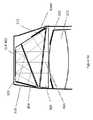
- FIG. 6illustrates a combination of an upper optical module 202 with a lower optical module 204 .
- the image light projected from the upper optical module 202may or may not be polarized.
- the image lightis reflected off a flat combiner element 602 such that it is directed towards the user's eye.
- the combiner element 602is a partial mirror that reflects image light while transmitting a substantial portion of light from the environment so the user can look through the combiner element and see the environment surrounding the HWC.
- the combiner 602may include a holographic pattern, to form a holographic mirror. If a monochrome image is desired, there may be a single wavelength reflection design for the holographic pattern on the surface of the combiner 602 . If the intention is to have multiple colors reflected from the surface of the combiner 602 , a multiple wavelength holographic mirror maybe included on the combiner surface. For example, in a three-color embodiment, where red, green and blue pixels are generated in the image light, the holographic mirror may be reflective to wavelengths substantially matching the wavelengths of the red, green and blue light provided by the light source. This configuration can be used as a wavelength specific mirror where pre-determined wavelengths of light from the image light are reflected to the user's eye.
- This configurationmay also be made such that substantially all other wavelengths in the visible pass through the combiner element 602 so the user has a substantially clear view of the surroundings when looking through the combiner element 602 .
- the transparency between the user's eye and the surroundingmay be approximately 80% when using a combiner that is a holographic mirror.
- holographic mirrorscan be made using lasers to produce interference patterns in the holographic material of the combiner where the wavelengths of the lasers correspond to the wavelengths of light that are subsequently reflected by the holographic mirror.
- the combiner element 602may include a notch mirror comprised of a multilayer coated substrate wherein the coating is designed to substantially reflect the wavelengths of light provided by the light source and substantially transmit the remaining wavelengths in the visible spectrum.
- the notch mirroris a tristimulus notch mirror wherein the multilayer coating is designed to reflect narrow bands of red, green and blue light that are matched to the what is provided by the light source and the remaining visible wavelengths are transmitted through the coating to enable a view of the environment through the combiner.
- the notch mirroris designed to reflect a single narrow band of light that is matched to the wavelength range of the light provided by the light source while transmitting the remaining visible wavelengths to enable a see-thru view of the environment.
- the combiner 602 with the notch mirrorwould operate, from the user's perspective, in a manner similar to the combiner that includes a holographic pattern on the combiner element 602 .
- the combiner, with the tristimulus notch mirrorwould reflect the “on” pixels to the eye because of the match between the reflective wavelengths of the notch mirror and the color of the image light, and the wearer would be able to see with high clarity the surroundings.
- the transparency between the user's eye and the surroundingmay be approximately 80% when using the tristimulus notch mirror.
- the image provided by the upper optical module 202 with the notch mirror combinercan provide higher contrast images than the holographic mirror combiner due to less scattering of the imaging light by the combiner.
- Lightcan escape through the combiner 602 and may produce face glow as the light is generally directed downward onto the cheek of the user.
- the escaping lightcan be trapped to avoid face glow.
- a linear polarizercan be laminated, or otherwise associated, to the combiner, with the transmission axis of the polarizer oriented relative to the polarized image light so that any escaping image light is absorbed by the polarizer.
- the image lightwould be polarized to provide S polarized light to the combiner for better reflection.
- the linear polarizer on the combinerwould be oriented to absorb S polarized light and pass P polarized light. This provides the preferred orientation of polarized sunglasses as well.
- a microlouvered filmsuch as a privacy filter can be used to absorb the escaping image light while providing the user with a see-thru view of the environment.
- the absorbance or transmittance of the microlouvered filmis dependent on the angle of the light. Where steep angle light is absorbed and light at less of an angle is transmitted.
- the combiner with the microlouver filmis angled at greater than 45 degrees to the optical axis of the image light (e.g. the combiner can be oriented at 50 degrees so the image light from the file lens is incident on the combiner at an oblique angle.
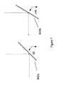
- FIG. 7illustrates an embodiment of a combiner element 602 at various angles when the combiner element 602 includes a holographic mirror.
- a mirrored surfacereflects light at an angle equal to the angle that the light is incident to the mirrored surface.
- the combiner elementbe at 45 degrees, 602 a , if the light is presented vertically to the combiner so the light can be reflected horizontally towards the wearer's eye.
- the incident lightcan be presented at angles other than vertical to enable the mirror surface to be oriented at other than 45 degrees, but in all cases wherein a mirrored surface is employed (including the tristimulus notch mirror described previously), the incident angle equals the reflected angle.
- a holographic mirror combinerincluded in embodiments, can be made such that light is reflected at a different angle from the angle that the light is incident onto the holographic mirrored surface. This allows freedom to select the angle of the combiner element 602 b independent of the angle of the incident image light and the angle of the light reflected into the wearer's eye.
- the angle of the combiner element 602 bis greater than 45 degrees (shown in FIG. 7 ) as this allows a more laterally compact HWC design.
- the increased angle of the combiner element 602 bdecreases the front to back width of the lower optical module 204 and may allow for a thinner HWC display (i.e. the furthest element from the wearer's eye can be closer to the wearer's face).
- FIG. 8illustrates another embodiment of a lower optical module 204 .
- polarized image lightprovided by the upper optical module 202 , is directed into the lower optical module 204 .
- the image lightreflects off a polarized mirror 804 and is directed to a focusing partially reflective mirror 802 , which is adapted to reflect the polarized light.
- An optical elementsuch as a 1 ⁇ 4wave film located between the polarized mirror 804 and the partially reflective mirror 802 , is used to change the polarization state of the image light such that the light reflected by the partially reflective mirror 802 is transmitted by the polarized mirror 804 to present image light to the eye of the wearer.
- the usercan also see through the polarized mirror 804 and the partially reflective mirror 802 to see the surrounding environment. As a result, the user perceives a combined image comprised of the displayed image light overlaid onto the see-thru view of the environment.
- the image light and dark light production and management functions described in connection with the upper modulemay be arranged to direct light in other directions (e.g. upward, sideward, etc.).
- the lower optical moduleis generally configured to deliver the image light to the wearer's eye and allow the wearer to see through the lower optical module, which may be accomplished through a variety of optical components.
- FIG. 8 aillustrates an embodiment of the present invention where the upper optical module 202 is arranged to direct image light into a TIR waveguide 810 .
- the upper optical module 202is positioned above the wearer's eye 812 and the light is directed horizontally into the TIR waveguide 810 .
- the TIR waveguideis designed to internally reflect the image light in a series of downward TIR reflections until it reaches the portion in front of the wearer's eye, where the light passes out of the TIR waveguide 812 into the wearer's eye.
- an outer shield 814is positioned in front of the TIR waveguide 810 .
- FIG. 8 billustrates an embodiment of the present invention where the upper optical module 202 is arranged to direct image light into a TIR waveguide 818 .
- the upper optical module 202is arranged on the side of the TIR waveguide 818 .
- the upper optical modulemay be positioned in the arm or near the arm of the HWC when configured as a pair of head worn glasses.
- the TIR waveguide 818is designed to internally reflect the image light in a series of TIR reflections until it reaches the portion in front of the wearer's eye, where the light passes out of the TIR waveguide 812 into the wearer's eye.
- FIG. 8 cillustrates yet further embodiments of the present invention where an upper optical module 202 is directing polarized image light into an optical guide 828 where the image light passes through a polarized reflector 824 , changes polarization state upon reflection of the optical element 822 which includes a 1 ⁇ 4wave film for example and then is reflected by the polarized reflector 824 towards the wearer's eye, due to the change in polarization of the image light.
- the upper optical module 202may be positioned to direct light to a mirror 820 , to position the upper optical module 202 laterally, in other embodiments, the upper optical module 202 may direct the image light directly towards the polarized reflector 824 . It should be understood that the present invention comprises other optical arrangements intended to direct image light into the wearer's eye.
- FIG. 9illustrates a system where the eye imaging camera 802 is mounted and angled such that the field of view of the eye imaging camera 802 is redirected toward the wearer's eye by the mirror pixels of the DLP 402 that are in the “off” state. In this way, the eye imaging camera 802 can be used to image the wearer's eye along the same optical axis as the displayed image that is presented to the wearer.
- image light that is presented to the wearer's eyeilluminates the wearer's eye so that the eye can be imaged by the eye imaging camera 802 .
- the light reflected by the eyepasses back though the optical train of the lower optical module 204 and a portion of the upper optical module to where the light is reflected by the “off” pixels of the DLP 402 toward the eye imaging camera 802 .
- the eye imaging cameramay image the wearer's eye at a moment in time where there are enough “off” pixels to achieve the required eye image resolution.
- the eye imaging cameracollects eye image information from “off” pixels over time and forms a time lapsed image.
- a modified imageis presented to the user wherein enough “off” state pixels are included that the camera can obtain the desired resolution and brightness for imaging the wearer's eye and the eye image capture is synchronized with the presentation of the modified image.
- the eye imaging systemmay be used for security systems.
- the HWCmay not allow access to the HWC or other system if the eye is not recognized (e.g. through eye characteristics including retina or iris characteristics, etc.).
- the HWCmay be used to provide constant security access in some embodiments.
- the eye security confirmationmay be a continuous, near-continuous, real-time, quasi real-time, periodic, etc. process so the wearer is effectively constantly being verified as known.
- the HWCmay be worn and eye security tracked for access to other computer systems.
- the eye imaging systemmay be used for control of the HWC.
- a blink, wink, or particular eye movementmay be used as a control mechanism for a software application operating on the HWC or associated device.
- the eye imaging systemmay be used in a process that determines how or when the HWC 102 delivers digitally displayed content to the wearer. For example, the eye imaging system may determine that the user is looking in a direction and then HWC may change the resolution in an area of the display or provide some content that is associated with something in the environment that the user may be looking at. Alternatively, the eye imaging system may identify different user's and change the displayed content or enabled features provided to the user. User's may be identified from a database of users eye characteristics either located on the HWC 102 or remotely located on the network 110 or on a server 112 .
- the HWCmay identify a primary user or a group of primary users from eye characteristics wherein the primary user(s) are provided with an enhanced set of features and all other user's are provided with a different set of features.
- the HWC 102uses identified eye characteristics to either enable features or not and eye characteristics need only be analyzed in comparison to a relatively small database of individual eye characteristics.
- FIG. 10illustrates a light source that may be used in association with the upper optics module 202 (e.g. polarized light source if the light from the solid state light source is polarized such as polarized light source 302 and 458 ), and light source 404 .
- the solid state light source 1002may be projected into a backlighting optical system 1004 .
- the solid state light source 1002may be one or more LEDs, laser diodes, OLEDs.
- the backlighting optical system 1004includes an extended section with a length/distance ratio of greater than 3, wherein the light undergoes multiple reflections from the sidewalls to mix of homogenize the light as supplied by the solid state light source 1002 .
- the backlighting optical system 1004can also include structures on the surface opposite (on the left side as shown in FIG. 10 ) to where the uniform light 1008 exits the backlight 1004 to change the direction of the light toward the DLP 302 and the reflective polarizer 310 or the DLP 402 and the TIR wedge 418 .
- the backlighting optical system 1004may also include structures to collimate the uniform light 1008 to provide light to the DLP with a smaller angular distribution or narrower cone angle.
- Diffusers or polarizerscan be used on the entrance or exit surface of the backlighting optical system. Diffusers can be used to spread or uniformize the exiting light from the backlight to improve the uniformity or increase the angular spread of the uniform light 1008 . Elliptical diffusers that diffuse the light more in some directions and less in others can be used to improve the uniformity or spread of the uniform light 1008 in directions orthogonal to the optical axis of the uniform light 1008 . Linear polarizers can be used to convert unpolarized light as supplied by the solid state light source 1002 to polarized light so the uniform light 1008 is polarized with a desired polarization state.
- a reflective polarizercan be used on the exit surface of the backlight 1004 to polarize the uniform light 1008 to the desired polarization state, while reflecting the other polarization state back into the backlight where it is recycled by multiple reflections within the backlight 1004 and at the solid state light source 1002 . Therefore by including a reflective polarizer at the exit surface of the backlight 1004 , the efficiency of the polarized light source is improved.
- FIGS. 10 a and 10 bshow illustrations of structures in backlight optical systems 1004 that can be used to change the direction of the light provided to the entrance face 1045 by the light source and then collimates the light in a direction lateral to the optical axis of the exiting uniform light 1008 .
- Structure 1060includes an angled sawtooth pattern in a transparent waveguide wherein the left edge of each sawtooth clips the steep angle rays of light thereby limiting the angle of the light being redirected. The steep surface at the right (as shown) of each sawtooth then redirects the light so that it reflects off the left angled surface of each sawtooth and is directed toward the exit surface 1040 .
- Structure 1050can be smooth and coated (e.g. with an aluminum coating or a dielectric mirror coating) to provide a high level of reflectivity without scattering.
- Structure 1050includes a curved face on the left side (as shown) to focus the rays after they pass through the exit surface 1040 , thereby providing a mechanism for collimating the uniform light 1008 .
- a diffusercan be provided between the solid state light source 1002 and the entrance face 1045 to homogenize the light provided by the solid state light source 1002 .
- a polarizercan be used between the diffuser and the entrance face 1045 of the backlight 1004 to provide a polarized light source.
- the polarization state of the lightcan be preserved from the entrance face 1045 to the exit face 1040 .
- the light entering the backlight from the solid state light source 1002passes through the polarizer so that it is polarized with the desired polarization state. If the polarizer is an absorptive linear polarizer, the light of the desired polarization state is transmitted while the light of the other polarization state is absorbed. If the polarizer is a reflective polarizer, the light of the desired polarization state is transmitted into the backlight 1004 while the light of the other polarization state is reflected back into the solid state light source 1002 where it can be recycled as previously described, to increase the efficiency of the polarized light source.
- FIG. 11 aillustrates a light source 1100 that may be used in association with the upper optics module 202 .
- the light source 1100may provide light to a backlighting optical system 1004 as described above in connection with FIG. 10 .
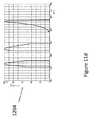
- the light source 1100includes a tristimulus notch filter 1102 .
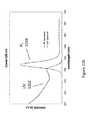
- the tristimulus notch filter 1102has narrow band pass filters for three wavelengths, as indicated in FIG. 11 c in a transmission graph 1108 .
- the graph shown in FIG. 11 b , as 1104illustrates an output of three different colored LEDs. One can see that the bandwidths of emission are narrow, but they have long tails.
- the tristimulus notch filter 1102can be used in connection with such LEDs to provide a light source 1100 that emits narrow filtered wavelengths of light as shown in FIG. 11 d as the transmission graph 1110 . Wherein the clipping effects of the tristimulus notch filter 1102 can be seen to have cut the tails from the LED emission graph 1104 to provide narrower wavelength bands of light to the upper optical module 202 .
- the light source 1100can be used in connection with a combiner 602 with a holographic mirror or tristimulus notch mirror to provide narrow bands of light that are reflected toward the wearer's eye with less waste light that does not get reflected by the combiner, thereby improving efficiency and reducing escaping light that can cause faceglow.
- FIG. 12 aillustrates another light source 1200 that may be used in association with the upper optics module 202 .
- the light source 1200may provide light to a backlighting optical system 1004 as described above in connection with FIG. 10 .
- the light source 1200includes a quantum dot cover glass 1202 . Where the quantum dots absorb light of a shorter wavelength and emit light of a longer wavelength ( FIG. 12 b shows an example wherein a UV spectrum 1202 applied to a quantum dot results in the quantum dot emitting a narrow band shown as a PL spectrum 1204 ) that is dependent on the material makeup and size of the quantum dot.
- quantum dots in the quantum dot cover glass 1202can be tailored to provide one or more bands of narrow bandwidth light (e.g. red, green and blue emissions dependent on the different quantum dots included as illustrated in the graph shown in FIG. 12 c where three different quantum dots are used.
- the LED driver lightemits UV light, deep blue or blue light.
- multiple light sources 1200would be used where each light source 1200 would include a quantum dot cover glass 1202 with a quantum dot selected to emit at one of the desired colors.
- the light source 1100can be used in connection with a combiner 602 with a holographic mirror or tristimulus notch mirror to provide narrow transmission bands of light that are reflected toward the wearer's eye with less waste light that does not get reflected.
- a solid state lighting systeme.g. LED, OLED, etc
- the solid state lighting systemmay be included inside the optical elements of an lower optical module 204 .
- the solid state lighting systemmay be arranged such that lighting effects outside of a field of view (FOV) of the presented digital content is presented to create an emersive effect for the person wearing the HWC.
- FOVfield of view
- the lighting effectsmay be presented to any portion of the HWC that is visible to the wearer.
- the solid state lighting systemmay be digitally controlled by an integrated processor on the HWC.
- the integrated processorwill control the lighting effects in coordination with digital content that is presented within the FOV of the HWC.
- a movie, picture, game, or other contentmay be displayed or playing within the FOV of the HWC.
- the contentmay show a bomb blast on the right side of the FOV and at the same moment, the solid state lighting system inside of the upper module optics may flash quickly in concert with the FOV image effect.
- the effectmay not be fast, it may be more persistent to indicate, for example, a general glow or color on one side of the user.
- the solid state lighting systemmay be color controlled, with red, green and blue LEDs, for example, such that color control can be coordinated with the digitally presented content within the field of view.
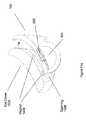
- FIG. 13 aillustrates optical components of a lower optical module 204 together with an outer lens 1302 .
- FIG. 13 aalso shows an embodiment including effects LED's 1308 a and 1308 b .
- FIG. 13 aillustrates image light 1312 , as described herein elsewhere, directed into the upper optical module where it will reflect off of the combiner element 1304 , as described herein elsewhere.
- the combiner element 1304 in this embodimentis angled towards the wearer's eye at the top of the module and away from the wearer's eye at the bottom of the module, as also illustrated and described in connection with FIG. 8 (e.g. at a 45 degree angle).
- the image light 1312provided by an upper optical module 202 (not shown in FIG.
- the wearer 13 areflects off of the combiner element 1304 towards the collimating mirror 1310 , away from the wearer's eye, as described herein elsewhere.
- the image light 1312then reflects and focuses off of the collimating mirror 1304 , passes back through the combiner element 1304 , and is directed into the wearer's eye.
- the wearercan also view the surrounding environment through the transparency of the combiner element 1304 , collimating mirror 1310 , and outer lens 1302 (if it is included).
- various surfacesare polarized to create the optical path for the image light and to provide transparency of the elements such that the wearer can view the surrounding environment. The wearer will generally perceive that the image light forms an image in the FOV 1305 .
- the outer lens 1302may be included.
- the outer lens 1302is an outer lens that may or may not be corrective and it may be designed to conceal the lower optical module components in an effort to make the HWC appear to be in a form similar to standard glasses or sunglasses.
- the effects LEDs 1308 a and 1308 bare positioned at the sides of the combiner element 1304 and the outer lens 1302 and/or the collimating mirror 1310 .
- the effects LEDs 1308 aare positioned within the confines defined by the combiner element 1304 and the outer lens 1302 and/or the collimating mirror.
- the effects LEDs 1308 a and 1308 bare also positioned outside of the FOV 1305 . In this arrangement, the effects LEDs 1308 a and 1308 b can provide lighting effects within the lower optical module outside of the FOV 1305 .
- the light emitted from the effects LEDs 1308 a and 1308 bmay be polarized such that the light passes through the combiner element 1304 toward the wearer's eye and does not pass through the outer lens 1302 and/or the collimating mirror 1310 .
- This arrangementprovides peripheral lighting effects to the wearer in a more private setting by not transmitting the lighting effects through the front of the HWC into the surrounding environment.
- the effects LEDs 1308 a and 1308 bmay be unpolarized so the lighting effects provided are made to be purposefully viewable by others in the environment for entertainment such as giving the effect of the wearer's eye glowing in correspondence to the image content being viewed by the wearer.
- FIG. 13 billustrates a cross section of the embodiment described in connection with FIG. 13 a .
- the effects LED 1308 ais located in the upper-front area inside of the optical components of the lower optical module. It should be understood that the effects LED 1308 a position in the described embodiments is only illustrative and alternate placements are encompassed by the present invention. Additionally, in embodiments, there may be one or more effects LEDs 1308 a in each of the two sides of HWC to provide peripheral lighting effects near one or both eyes of the wearer.
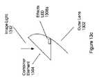
- FIG. 13 cillustrates an embodiment where the combiner element 1304 is angled away from the eye at the top and towards the eye at the bottom (e.g. in accordance with the holographic or notch filter embodiments described herein).
- the effects LED 1308 ais located on the outer lens 1302 side of the combiner element 1304 to provide a concealed appearance of the lighting effects.
- the effects LED 1308 a of FIG. 13 cmay include a polarizer such that the emitted light can pass through a polarized element associated with the combiner element 1304 and be blocked by a polarized element associated with the outer lens 1302 .
- Another aspect of the present inventionrelates to the mitigation of light escaping from the space between the wearer's face and the HWC itself.
- Another aspect of the present inventionrelates to maintaining a controlled lighting environment in proximity to the wearer's eyes.
- both the maintenance of the lighting environment and the mitigation of light escapeare accomplished by including a removable and replaceable flexible shield for the HWC.
- the removable and replaceable shieldcan be provided for one eye or both eyes in correspondence to the use of the displays for each eye. For example, in a night vision application, the display to only one eye could be used for night vision while the display to the other eye is turned off to provide good see-thru when moving between areas where visible light is available and dark areas where night vision enhancement is needed.
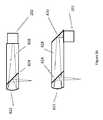
- FIG. 14 aillustrates a removable and replaceable flexible eye cover 1402 with an opening 1408 that can be attached and removed quickly from the HWC 102 through the use of magnets.
- magnetsmay be included in the eye cover 1402 and magnets of an opposite polarity may be included (e.g. embedded) in the frame of the HWC 102 .
- the magnets of the two elementswould attract quite strongly with the opposite polarity configuration.
- one of the elementsmay have a magnet and the other side may have metal for the attraction.
- the eye cover 1402is a flexible elastomeric shield.
- the eye cover 1402may be an elastomeric bellows design to accommodate flexibility and more closely align with the wearer's face.
- FIG. 14 billustrates a removable and replaceable flexible eye cover 1404 that is adapted as a single eye cover.
- a single eye covermay be used for each side of the HWC to cover both eyes of the wearer.
- the single eye covermay be used in connection with a HWC that includes only one computer display for one eye. These configurations prevent light that is generated and directed generally towards the wearer's face by covering the space between the wearer's face and the HWC.
- the opening 1408allows the wearer to look through the opening 1408 to view the displayed content and the surrounding environment through the front of the HWC.
- the image light in the lower optical module 204can be prevented from emitting from the front of the HWC through internal optics polarization schemes, as described herein, for example.
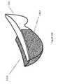
- FIG. 14 cillustrates another embodiment of a light suppression system.
- the eye cover 1410may be similar to the eye cover 1402 , but eye cover 1410 includes a front light shield 1412 .
- the front light shield 1412may be opaque to prevent light from escaping the front lens of the HWC.
- the front light shield 1412is polarized to prevent light from escaping the front lens.
- the internal optical elements of the HWCe.g. of the lower optical module 204
- the front light shield 1412may be polarized to prevent the light from transmitting through the front light shield 1412 .
- an opaque front light shield 1412may be included and the digital content may include images of the surrounding environment such that the wearer can visualize the surrounding environment.
- One eyemay be presented with night vision environmental imagery and this eye's surrounding environment optical path may be covered using an opaque front light shield 1412 .
- this arrangementmay be associated with both eyes.
- the display lighting and/or effects lightingmay be controlled in a manner suitable for when an eye cover 1408 is attached or removed from the HWC 102 .
- the lighting system(s) in the HWCmay go into a low light mode to further control any amounts of stray light escaping from the HWC and the areas around the HWC.
- Covert operations at night, while using night vision or standard vision,may require a solution which prevents as much escaping light as possible so a user may clip on the eye cover(s) 1408 and then the HWC may go into a low light mode.
- the low light modemay, in some embodiments, only go into a low light mode when the eye cover 1408 is attached if the HWC identifies that the environment is in low light conditions (e.g. through environment light level sensor detection).
- the low light levelmay be determined to be at an intermediate point between full and low light dependent on environmental conditions.
- Another aspect of the present inventionrelates to automatically controlling the type of content displayed in the HWC when eye covers 1408 are attached or removed from the HWC.
- the displayed contentmay be restricted in amount or in color amounts.
- the display(s)may go into a simple content delivery mode to restrict the amount of information displayed. This may be done to reduce the amount of light produced by the display(s).
- the display(s)may change from color displays to monochrome displays to reduce the amount of light produced.
- the monochrome lightingmay be red to limit the impact on the wearer's eyes to maintain an ability to see better in the dark.
Landscapes
- Physics & Mathematics (AREA)
- General Physics & Mathematics (AREA)
- Optics & Photonics (AREA)
Abstract
Description
Critical angle=arc−sin(1/n)
Claims (18)
Priority Applications (1)
| Application Number | Priority Date | Filing Date | Title |
|---|---|---|---|
| US14/543,751US9298002B2 (en) | 2014-01-21 | 2014-11-17 | Optical configurations for head worn computing |
Applications Claiming Priority (4)
| Application Number | Priority Date | Filing Date | Title |
|---|---|---|---|
| US14/160,377US20150205111A1 (en) | 2014-01-21 | 2014-01-21 | Optical configurations for head worn computing |
| US14/163,646US9400390B2 (en) | 2014-01-24 | 2014-01-24 | Peripheral lighting for head worn computing |
| US14/172,901US20150277120A1 (en) | 2014-01-21 | 2014-02-04 | Optical configurations for head worn computing |
| US14/543,751US9298002B2 (en) | 2014-01-21 | 2014-11-17 | Optical configurations for head worn computing |
Related Parent Applications (1)
| Application Number | Title | Priority Date | Filing Date |
|---|---|---|---|
| US14/172,901ContinuationUS20150277120A1 (en) | 2008-12-16 | 2014-02-04 | Optical configurations for head worn computing |
Publications (2)
| Publication Number | Publication Date |
|---|---|
| US20150205125A1 US20150205125A1 (en) | 2015-07-23 |
| US9298002B2true US9298002B2 (en) | 2016-03-29 |
Family
ID=53544638
Family Applications (3)
| Application Number | Title | Priority Date | Filing Date |
|---|---|---|---|
| US14/172,901AbandonedUS20150277120A1 (en) | 2008-12-16 | 2014-02-04 | Optical configurations for head worn computing |
| US14/205,267Active2034-02-18US9298001B2 (en) | 2014-01-21 | 2014-03-11 | Optical configurations for head worn computing |
| US14/543,751ActiveUS9298002B2 (en) | 2014-01-21 | 2014-11-17 | Optical configurations for head worn computing |
Family Applications Before (2)
| Application Number | Title | Priority Date | Filing Date |
|---|---|---|---|
| US14/172,901AbandonedUS20150277120A1 (en) | 2008-12-16 | 2014-02-04 | Optical configurations for head worn computing |
| US14/205,267Active2034-02-18US9298001B2 (en) | 2014-01-21 | 2014-03-11 | Optical configurations for head worn computing |
Country Status (1)
| Country | Link |
|---|---|
| US (3) | US20150277120A1 (en) |
Cited By (82)
| Publication number | Priority date | Publication date | Assignee | Title |
|---|---|---|---|---|
| US9494800B2 (en) | 2014-01-21 | 2016-11-15 | Osterhout Group, Inc. | See-through computer display systems |
| US9523856B2 (en) | 2014-01-21 | 2016-12-20 | Osterhout Group, Inc. | See-through computer display systems |
| US9529192B2 (en) | 2014-01-21 | 2016-12-27 | Osterhout Group, Inc. | Eye imaging in head worn computing |
| US9529195B2 (en) | 2014-01-21 | 2016-12-27 | Osterhout Group, Inc. | See-through computer display systems |
| US9547465B2 (en) | 2014-02-14 | 2017-01-17 | Osterhout Group, Inc. | Object shadowing in head worn computing |
| US9575321B2 (en) | 2014-06-09 | 2017-02-21 | Osterhout Group, Inc. | Content presentation in head worn computing |
| US9594246B2 (en) | 2014-01-21 | 2017-03-14 | Osterhout Group, Inc. | See-through computer display systems |
| US9615742B2 (en) | 2014-01-21 | 2017-04-11 | Osterhout Group, Inc. | Eye imaging in head worn computing |
| US9651784B2 (en) | 2014-01-21 | 2017-05-16 | Osterhout Group, Inc. | See-through computer display systems |
| US9651787B2 (en) | 2014-04-25 | 2017-05-16 | Osterhout Group, Inc. | Speaker assembly for headworn computer |
| US9671613B2 (en) | 2014-09-26 | 2017-06-06 | Osterhout Group, Inc. | See-through computer display systems |
| US9672210B2 (en) | 2014-04-25 | 2017-06-06 | Osterhout Group, Inc. | Language translation with head-worn computing |
| US9684172B2 (en) | 2014-12-03 | 2017-06-20 | Osterhout Group, Inc. | Head worn computer display systems |
| USD792400S1 (en) | 2014-12-31 | 2017-07-18 | Osterhout Group, Inc. | Computer glasses |
| US9715112B2 (en) | 2014-01-21 | 2017-07-25 | Osterhout Group, Inc. | Suppression of stray light in head worn computing |
| US9720234B2 (en) | 2014-01-21 | 2017-08-01 | Osterhout Group, Inc. | See-through computer display systems |
| USD794637S1 (en) | 2015-01-05 | 2017-08-15 | Osterhout Group, Inc. | Air mouse |
| US9740280B2 (en) | 2014-01-21 | 2017-08-22 | Osterhout Group, Inc. | Eye imaging in head worn computing |
| US9746686B2 (en) | 2014-05-19 | 2017-08-29 | Osterhout Group, Inc. | Content position calibration in head worn computing |
| US9753288B2 (en) | 2014-01-21 | 2017-09-05 | Osterhout Group, Inc. | See-through computer display systems |
| US9766463B2 (en) | 2014-01-21 | 2017-09-19 | Osterhout Group, Inc. | See-through computer display systems |
| US9784973B2 (en) | 2014-02-11 | 2017-10-10 | Osterhout Group, Inc. | Micro doppler presentations in head worn computing |
| US9798148B2 (en) | 2014-07-08 | 2017-10-24 | Osterhout Group, Inc. | Optical configurations for head-worn see-through displays |
| US9810906B2 (en) | 2014-06-17 | 2017-11-07 | Osterhout Group, Inc. | External user interface for head worn computing |
| US9811152B2 (en) | 2014-01-21 | 2017-11-07 | Osterhout Group, Inc. | Eye imaging in head worn computing |
| US9812096B2 (en) | 2008-01-23 | 2017-11-07 | Spy Eye, Llc | Eye mounted displays and systems using eye mounted displays |
| US9829707B2 (en) | 2014-08-12 | 2017-11-28 | Osterhout Group, Inc. | Measuring content brightness in head worn computing |
| US9836122B2 (en) | 2014-01-21 | 2017-12-05 | Osterhout Group, Inc. | Eye glint imaging in see-through computer display systems |
| US9843093B2 (en) | 2014-02-11 | 2017-12-12 | Osterhout Group, Inc. | Spatial location presentation in head worn computing |
| US9841599B2 (en) | 2014-06-05 | 2017-12-12 | Osterhout Group, Inc. | Optical configurations for head-worn see-through displays |
| US9910284B1 (en) | 2016-09-08 | 2018-03-06 | Osterhout Group, Inc. | Optical systems for head-worn computers |
| US9939934B2 (en) | 2014-01-17 | 2018-04-10 | Osterhout Group, Inc. | External user interface for head worn computing |
| US9939646B2 (en) | 2014-01-24 | 2018-04-10 | Osterhout Group, Inc. | Stray light suppression for head worn computing |
| US9952664B2 (en) | 2014-01-21 | 2018-04-24 | Osterhout Group, Inc. | Eye imaging in head worn computing |
| US9965681B2 (en) | 2008-12-16 | 2018-05-08 | Osterhout Group, Inc. | Eye imaging in head worn computing |
| US9993335B2 (en) | 2014-01-08 | 2018-06-12 | Spy Eye, Llc | Variable resolution eye mounted displays |
| US10062182B2 (en) | 2015-02-17 | 2018-08-28 | Osterhout Group, Inc. | See-through computer display systems |
| US10078224B2 (en) | 2014-09-26 | 2018-09-18 | Osterhout Group, Inc. | See-through computer display systems |
| US10191279B2 (en) | 2014-03-17 | 2019-01-29 | Osterhout Group, Inc. | Eye imaging in head worn computing |
| US10254856B2 (en) | 2014-01-17 | 2019-04-09 | Osterhout Group, Inc. | External user interface for head worn computing |
| US10422995B2 (en) | 2017-07-24 | 2019-09-24 | Mentor Acquisition One, Llc | See-through computer display systems with stray light management |
| US10466491B2 (en) | 2016-06-01 | 2019-11-05 | Mentor Acquisition One, Llc | Modular systems for head-worn computers |
| US10505394B2 (en) | 2018-04-21 | 2019-12-10 | Tectus Corporation | Power generation necklaces that mitigate energy absorption in the human body |
| US10529107B1 (en) | 2018-09-11 | 2020-01-07 | Tectus Corporation | Projector alignment in a contact lens |
| US10558050B2 (en) | 2014-01-24 | 2020-02-11 | Mentor Acquisition One, Llc | Haptic systems for head-worn computers |
| US10578869B2 (en) | 2017-07-24 | 2020-03-03 | Mentor Acquisition One, Llc | See-through computer display systems with adjustable zoom cameras |
| US10644543B1 (en) | 2018-12-20 | 2020-05-05 | Tectus Corporation | Eye-mounted display system including a head wearable object |
| US10649220B2 (en) | 2014-06-09 | 2020-05-12 | Mentor Acquisition One, Llc | Content presentation in head worn computing |
| US10649233B2 (en) | 2016-11-28 | 2020-05-12 | Tectus Corporation | Unobtrusive eye mounted display |
| US10663740B2 (en) | 2014-06-09 | 2020-05-26 | Mentor Acquisition One, Llc | Content presentation in head worn computing |
| US10673414B2 (en) | 2018-02-05 | 2020-06-02 | Tectus Corporation | Adaptive tuning of a contact lens |
| US10684687B2 (en) | 2014-12-03 | 2020-06-16 | Mentor Acquisition One, Llc | See-through computer display systems |
| US10684478B2 (en) | 2016-05-09 | 2020-06-16 | Mentor Acquisition One, Llc | User interface systems for head-worn computers |
| US10790700B2 (en) | 2018-05-18 | 2020-09-29 | Tectus Corporation | Power generation necklaces with field shaping systems |
| US10824253B2 (en) | 2016-05-09 | 2020-11-03 | Mentor Acquisition One, Llc | User interface systems for head-worn computers |
| US10838239B2 (en) | 2018-04-30 | 2020-11-17 | Tectus Corporation | Multi-coil field generation in an electronic contact lens system |
| US10838232B2 (en) | 2018-11-26 | 2020-11-17 | Tectus Corporation | Eye-mounted displays including embedded solenoids |
| US10845621B1 (en) | 2019-08-02 | 2020-11-24 | Tectus Corporation | Headgear providing inductive coupling to a contact lens, with controller |
| US10853589B2 (en) | 2014-04-25 | 2020-12-01 | Mentor Acquisition One, Llc | Language translation with head-worn computing |
| US10895762B2 (en) | 2018-04-30 | 2021-01-19 | Tectus Corporation | Multi-coil field generation in an electronic contact lens system |
| US10901505B1 (en) | 2019-10-24 | 2021-01-26 | Tectus Corporation | Eye-based activation and tool selection systems and methods |
| US10969584B2 (en) | 2017-08-04 | 2021-04-06 | Mentor Acquisition One, Llc | Image expansion optic for head-worn computer |
| US11103122B2 (en) | 2014-07-15 | 2021-08-31 | Mentor Acquisition One, Llc | Content presentation in head worn computing |
| US11104272B2 (en) | 2014-03-28 | 2021-08-31 | Mentor Acquisition One, Llc | System for assisted operator safety using an HMD |
| US11137622B2 (en) | 2018-07-15 | 2021-10-05 | Tectus Corporation | Eye-mounted displays including embedded conductive coils |
| US11227294B2 (en) | 2014-04-03 | 2022-01-18 | Mentor Acquisition One, Llc | Sight information collection in head worn computing |
| US11237389B1 (en)* | 2019-02-11 | 2022-02-01 | Facebook Technologies, Llc | Wedge combiner for eye-tracking |
| US11269182B2 (en) | 2014-07-15 | 2022-03-08 | Mentor Acquisition One, Llc | Content presentation in head worn computing |
| US11409105B2 (en) | 2017-07-24 | 2022-08-09 | Mentor Acquisition One, Llc | See-through computer display systems |
| US11487110B2 (en) | 2014-01-21 | 2022-11-01 | Mentor Acquisition One, Llc | Eye imaging in head worn computing |
| US11592899B1 (en) | 2021-10-28 | 2023-02-28 | Tectus Corporation | Button activation within an eye-controlled user interface |
| US11619994B1 (en) | 2022-01-14 | 2023-04-04 | Tectus Corporation | Control of an electronic contact lens using pitch-based eye gestures |
| US11662807B2 (en) | 2020-01-06 | 2023-05-30 | Tectus Corporation | Eye-tracking user interface for virtual tool control |
| US11669163B2 (en) | 2014-01-21 | 2023-06-06 | Mentor Acquisition One, Llc | Eye glint imaging in see-through computer display systems |
| US11737666B2 (en) | 2014-01-21 | 2023-08-29 | Mentor Acquisition One, Llc | Eye imaging in head worn computing |
| US11874961B2 (en) | 2022-05-09 | 2024-01-16 | Tectus Corporation | Managing display of an icon in an eye tracking augmented reality device |
| US11892644B2 (en) | 2014-01-21 | 2024-02-06 | Mentor Acquisition One, Llc | See-through computer display systems |
| US11907417B2 (en) | 2019-07-25 | 2024-02-20 | Tectus Corporation | Glance and reveal within a virtual environment |
| US12093453B2 (en) | 2014-01-21 | 2024-09-17 | Mentor Acquisition One, Llc | Eye glint imaging in see-through computer display systems |
| US12105281B2 (en) | 2014-01-21 | 2024-10-01 | Mentor Acquisition One, Llc | See-through computer display systems |
| US12135471B2 (en) | 2021-09-10 | 2024-11-05 | Tectus Corporation | Control of an electronic contact lens using eye gestures |
| US12443294B2 (en) | 2024-06-24 | 2025-10-14 | Mentor Acquisition One, Llc | External user interface for head worn computing |
Families Citing this family (14)
| Publication number | Priority date | Publication date | Assignee | Title |
|---|---|---|---|---|
| US20150205111A1 (en) | 2014-01-21 | 2015-07-23 | Osterhout Group, Inc. | Optical configurations for head worn computing |
| US20150277120A1 (en) | 2014-01-21 | 2015-10-01 | Osterhout Group, Inc. | Optical configurations for head worn computing |
| US20150277118A1 (en) | 2014-03-28 | 2015-10-01 | Osterhout Group, Inc. | Sensor dependent content position in head worn computing |
| US9448409B2 (en) | 2014-11-26 | 2016-09-20 | Osterhout Group, Inc. | See-through computer display systems |
| US9310610B2 (en) | 2014-01-21 | 2016-04-12 | Osterhout Group, Inc. | See-through computer display systems |
| US9423842B2 (en) | 2014-09-18 | 2016-08-23 | Osterhout Group, Inc. | Thermal management for head-worn computer |
| USD743963S1 (en) | 2014-12-22 | 2015-11-24 | Osterhout Group, Inc. | Air mouse |
| US10139966B2 (en) | 2015-07-22 | 2018-11-27 | Osterhout Group, Inc. | External user interface for head worn computing |
| US20170017323A1 (en)* | 2015-07-17 | 2017-01-19 | Osterhout Group, Inc. | External user interface for head worn computing |
| US11003246B2 (en) | 2015-07-22 | 2021-05-11 | Mentor Acquisition One, Llc | External user interface for head worn computing |
| US10152141B1 (en) | 2017-08-18 | 2018-12-11 | Osterhout Group, Inc. | Controller movement tracking with light emitters |
| DE102018209368B4 (en) | 2018-06-12 | 2020-01-02 | Fraunhofer-Gesellschaft zur Förderung der angewandten Forschung e.V. | Optics for transmitting and / or receiving element, communication module, arrays of communication modules, system of several communication modules and method for producing an optic |
| FR3106419A1 (en)* | 2020-01-21 | 2021-07-23 | Institut Mines Telecom | Contact lens for augmented reality and corresponding method |
| CN116413911B (en)* | 2021-12-31 | 2025-08-01 | 北京耐德佳显示技术有限公司 | Ultra-thin lens, virtual image imaging device using same and near-eye display |
Citations (167)
| Publication number | Priority date | Publication date | Assignee | Title |
|---|---|---|---|---|
| US3305294A (en) | 1964-12-03 | 1967-02-21 | Optical Res & Dev Corp | Two-element variable-power spherical lens |
| EP0368898A1 (en) | 1987-06-12 | 1990-05-23 | Hughes Flight Dynamics, Inc. | Windshield display system for an automobile |
| US5257094A (en) | 1991-07-30 | 1993-10-26 | Larussa Joseph | Helmet mounted display system |
| US5621424A (en) | 1992-08-24 | 1997-04-15 | Olympus Optical Co., Ltd. | Head mount display apparatus allowing easy switching operation from electronic image to external field image |
| EP0777867A1 (en) | 1994-08-24 | 1997-06-11 | James L. Fergason | Head mounted display and viewing system using a remote retro-reflector and method of displaying and viewing an image |
| US5699194A (en) | 1996-02-13 | 1997-12-16 | Olympus Optical Co., Ltd. | Image display apparatus comprising an internally reflecting ocular optical system |
| US5717422A (en) | 1994-01-25 | 1998-02-10 | Fergason; James L. | Variable intensity high contrast passive display |
| US5914818A (en) | 1996-11-29 | 1999-06-22 | Texas Instruments Incorporated | Offset projection lens for use with reflective spatial light modulators |
| US5949583A (en) | 1992-02-07 | 1999-09-07 | I-O Display Systems Llc | Head-mounted display with image generator, fold mirror and mirror for transmission to the eye position of the user |
| US6222677B1 (en) | 1999-04-12 | 2001-04-24 | International Business Machines Corporation | Compact optical system for use in virtual display applications |
| US20010019240A1 (en) | 1999-12-09 | 2001-09-06 | Kenji Takahashi | Display apparatus |
| US20020005108A1 (en) | 1998-05-15 | 2002-01-17 | Ludwig Lester Frank | Tactile, visual, and array controllers for real-time control of music signal processing, mixing, video, and lighting |
| US20020109903A1 (en) | 2000-12-21 | 2002-08-15 | Toshiyuki Kaeriyama | Micro-electromechanical system |
| US6456438B1 (en) | 1999-08-12 | 2002-09-24 | Honeywell Inc. | Variable immersion vignetting display |
| US6461000B1 (en) | 1999-06-29 | 2002-10-08 | U.S. Precision Lens Incorporated | Optical systems for projection displays |
| US6478429B1 (en)* | 1998-10-29 | 2002-11-12 | Fujitsu Limited | Reflective projector |
| US20030030912A1 (en) | 2000-10-20 | 2003-02-13 | Gleckman Philip Landon | Compact wide field of view imaging system |
| US20040066547A1 (en) | 2002-10-04 | 2004-04-08 | William Parker | Full color holographic image combiner system |
| US6847336B1 (en) | 1996-10-02 | 2005-01-25 | Jerome H. Lemelson | Selectively controllable heads-up display system |
| US6987787B1 (en) | 2004-06-28 | 2006-01-17 | Rockwell Collins | LED brightness control system for a wide-range of luminance control |
| US7016116B2 (en) | 1996-08-16 | 2006-03-21 | Eugene Dolgoff | Three-dimensional display system |
| US20060098293A1 (en) | 2004-09-08 | 2006-05-11 | John Garoutte | Wearable display system |
| US7088234B2 (en) | 2001-11-27 | 2006-08-08 | Matsushita Electric Industrial Co., Ltd. | Wearing information notifying unit |
| US20060250322A1 (en) | 2005-05-09 | 2006-11-09 | Optics 1, Inc. | Dynamic vergence and focus control for head-mounted displays |
| US20070024823A1 (en) | 2005-07-29 | 2007-02-01 | Optoma Technology, Inc. | Methods and systems for improving operation of a video projector |
| US20070024763A1 (en) | 2005-07-29 | 2007-02-01 | Chung Yau W | Methods and systems for displaying video on an adjustable screen |
| US20070025273A1 (en) | 2005-07-29 | 2007-02-01 | Chung Yau W | Methods and systems for detecting video signals and sources |
| US20070024750A1 (en) | 2005-07-29 | 2007-02-01 | Yau Wing Chung | Methods and systems for displaying video in multiple aspect ratios |
| US20070024764A1 (en)* | 2005-07-29 | 2007-02-01 | Optoma Technology, Inc. | Methods and systems that compensate for distortion introduced by anamorphic lenses in a video projector |
| US20070024820A1 (en) | 2005-07-29 | 2007-02-01 | Optoma Technology, Inc. | Methods and systems for calibrating rear projection video |
| US20070030456A1 (en) | 2005-07-29 | 2007-02-08 | Duncan John E | Polarizing beam splitter |
| US7199934B2 (en) | 2004-05-06 | 2007-04-03 | Olympus Corporation | Head-mounted display apparatus |
| US20080191965A1 (en) | 2007-02-09 | 2008-08-14 | Raffaele Martini Pandozy | Apparatus and method for eye exercises |
| US7417617B2 (en) | 1999-05-18 | 2008-08-26 | Dimension Technologies, Inc. | Enhanced resolution for image generation |
| US20080266645A1 (en) | 2006-11-07 | 2008-10-30 | Agency For Science, Technology And Research | Device and method to realize a light processor |
| US7457040B2 (en) | 2002-03-21 | 2008-11-25 | Lumus Ltd. | Light guide optical device |
| US20090015735A1 (en) | 2005-11-10 | 2009-01-15 | Michael David Simmonds | Display source |
| US20090040296A1 (en) | 2007-08-06 | 2009-02-12 | Moscato Jonathan D | Head mounted display assembly |
| US20090279180A1 (en) | 2004-06-17 | 2009-11-12 | Yaakov Amitai | High brightness optical device |
| US20100007852A1 (en) | 2008-07-11 | 2010-01-14 | Bietry Joseph R | Laser illuminated micro-mirror projector |
| US7690799B2 (en) | 2008-08-26 | 2010-04-06 | Microvision, Inc. | Optical relay for compact head up display |
| US20100103075A1 (en) | 2008-10-24 | 2010-04-29 | Yahoo! Inc. | Reconfiguring reality using a reality overlay device |
| US20100130140A1 (en) | 2007-03-29 | 2010-05-27 | Kyocera Corporation | Portable wireless device |
| US7728799B2 (en) | 2001-06-15 | 2010-06-01 | Apple Inc. | Active enclosure for computing device |
| US20100149073A1 (en) | 2008-11-02 | 2010-06-17 | David Chaum | Near to Eye Display System and Appliance |
| US7777960B2 (en) | 2007-09-10 | 2010-08-17 | Microvision, Inc. | Wide field of view head-up display system |
| US7830370B2 (en) | 2000-06-06 | 2010-11-09 | Semiconductor Energy Laboratory Co., Ltd. | Display device and method of manufacturing the same |
| US20100283774A1 (en) | 2008-01-11 | 2010-11-11 | Essilor International (Compagnie Generale D'optique) | Transparent component with switchable reflecting elements, and devices including such component |
| US7855743B2 (en) | 2006-09-08 | 2010-12-21 | Sony Corporation | Image capturing and displaying apparatus and image capturing and displaying method |
| US7928926B2 (en) | 2006-06-27 | 2011-04-19 | Panasonic Corporation | Display apparatus and method for hands free operation that selects a function when window is within field of view |
| US20110131495A1 (en) | 2007-09-06 | 2011-06-02 | Apple Inc. | Graphical representation of assets stored on a portable media device |
| US20110130958A1 (en) | 2009-11-30 | 2011-06-02 | Apple Inc. | Dynamic alerts for calendar events |
| US20110164163A1 (en) | 2010-01-05 | 2011-07-07 | Apple Inc. | Synchronized, interactive augmented reality displays for multifunction devices |
| US20110164221A1 (en) | 2010-01-04 | 2011-07-07 | Elbit Systems Of America, Llc | System and Method for Efficiently Delivering Rays from a Light Source to Create an Image |
| US20110164047A1 (en) | 2010-01-06 | 2011-07-07 | Apple Inc. | Transparent electronic device |
| US20110196610A1 (en) | 2010-02-05 | 2011-08-11 | Apple Inc. | Schematic maps |
| US20110199171A1 (en) | 2007-06-07 | 2011-08-18 | Apple Inc. | Multi-Position Magnetic Detents |
| US20110201213A1 (en) | 2010-02-18 | 2011-08-18 | Apple Inc. | Low profile connector system |
| US20110202823A1 (en) | 2007-08-06 | 2011-08-18 | Apple Inc. | Pasting a set of cells |
| US8018579B1 (en) | 2005-10-21 | 2011-09-13 | Apple Inc. | Three-dimensional imaging and display system |
| US20110248963A1 (en)* | 2008-12-24 | 2011-10-13 | Lawrence Nicholas A | Touch Sensitive Image Display |
| WO2011143655A1 (en) | 2010-05-14 | 2011-11-17 | Advitech, Inc. | System and method for prevention and control of the effects of spatial disorientation |
| US20120035934A1 (en) | 2010-08-06 | 2012-02-09 | Dynavox Systems Llc | Speech generation device with a projected display and optical inputs |
| US20120050493A1 (en) | 2010-08-24 | 2012-03-01 | Siemens Corporation | Geometric calibration of head-worn multi-camera eye tracking system |
| US20120075168A1 (en)* | 2010-09-14 | 2012-03-29 | Osterhout Group, Inc. | Eyepiece with uniformly illuminated reflective display |
| US20120092328A1 (en) | 2010-10-15 | 2012-04-19 | Jason Flaks | Fusing virtual content into real content |
| US8166421B2 (en) | 2008-01-14 | 2012-04-24 | Primesense Ltd. | Three-dimensional user interface |
| WO2012058175A1 (en) | 2010-10-28 | 2012-05-03 | Eastman Kodak Company | Method of operating a head-mounted display for prevention of motion sickness |
| US20120120103A1 (en) | 2010-02-28 | 2012-05-17 | Osterhout Group, Inc. | Alignment control in an augmented reality headpiece |
| US20120119978A1 (en) | 2010-02-28 | 2012-05-17 | Osterhout Group, Inc. | Light control in head mounted displays |
| WO2012064546A1 (en) | 2010-11-08 | 2012-05-18 | Microsoft Corporation | Automatic variable virtual focus for augmented reality displays |
| WO2012082807A2 (en) | 2010-12-17 | 2012-06-21 | Microsoft Corporation | Optimized focal area for augmented reality displays |
| US8212859B2 (en) | 2006-10-13 | 2012-07-03 | Apple Inc. | Peripheral treatment for head-mounted displays |
| US20120176682A1 (en) | 2011-01-10 | 2012-07-12 | Microvision, Inc. | Substrate Guided Relay Having A Homogenizing Layer |
| US20120188245A1 (en) | 2011-01-20 | 2012-07-26 | Apple Inc. | Display resolution increase with mechanical actuation |
| US20120194553A1 (en) | 2010-02-28 | 2012-08-02 | Osterhout Group, Inc. | Ar glasses with sensor and user action based control of external devices with feedback |
| US20120200935A1 (en) | 2011-02-04 | 2012-08-09 | Seiko Epson Corporation | Virtual image display apparatus |
| EP2486450A1 (en) | 2008-11-02 | 2012-08-15 | David Chaum | Near to eye display system and appliance |
| US8246170B2 (en) | 2007-11-21 | 2012-08-21 | Panasonic Corporation | Display apparatus |
| US20120212398A1 (en) | 2010-02-28 | 2012-08-23 | Osterhout Group, Inc. | See-through near-eye display glasses including a partially reflective, partially transmitting optical element |
| US20120212593A1 (en) | 2011-02-17 | 2012-08-23 | Orcam Technologies Ltd. | User wearable visual assistance system |
| US20120223885A1 (en) | 2011-03-02 | 2012-09-06 | Microsoft Corporation | Immersive display experience |
| WO2012118575A2 (en) | 2011-02-28 | 2012-09-07 | Osterhout Group, Inc. | Alignment control in an augmented reality headpiece |
| US20120229367A1 (en) | 2009-11-21 | 2012-09-13 | Douglas Peter Magyari | Head mounted display device |
| EP2502410A1 (en) | 2009-11-19 | 2012-09-26 | eSight Corporation | Image magnification on a head mounted display |
| US20120242251A1 (en) | 2009-12-18 | 2012-09-27 | Koninklijke Philips Electronics N.V. | Ambience lighting system using global content characteristics |
| US20120250152A1 (en) | 2011-03-31 | 2012-10-04 | Honeywell International Inc. | Variable focus stereoscopic display system and method |
| US20120264510A1 (en) | 2011-04-12 | 2012-10-18 | Microsoft Corporation | Integrated virtual environment |
| US20120293548A1 (en) | 2011-05-20 | 2012-11-22 | Microsoft Corporation | Event augmentation with real-time information |
| US20120306850A1 (en) | 2011-06-02 | 2012-12-06 | Microsoft Corporation | Distributed asynchronous localization and mapping for augmented reality |
| US20120327116A1 (en) | 2011-06-23 | 2012-12-27 | Microsoft Corporation | Total field of view classification for head-mounted display |
| US20130009366A1 (en) | 2007-10-23 | 2013-01-10 | Weatherford/Lamb, Inc. | Low Profile Rotating Control Device |
| US8378924B2 (en) | 2007-01-12 | 2013-02-19 | Kopin Corporation | Monocular display device |
| US8376548B2 (en) | 2010-09-22 | 2013-02-19 | Vuzix Corporation | Near-eye display with on-axis symmetry |
| US20130070344A1 (en) | 2011-09-15 | 2013-03-21 | Seiko Epson Corporation | Virtual image display device and manufacturing method of virtual image display device |
| WO2013043288A2 (en) | 2011-09-21 | 2013-03-28 | Google Inc. | Wearable computer with superimposed controls and instructions for external device |
| WO2013049248A2 (en) | 2011-09-26 | 2013-04-04 | Osterhout Group, Inc. | Video display modification based on sensor input for a see-through near-to-eye display |
| US20130083055A1 (en) | 2011-09-30 | 2013-04-04 | Apple Inc. | 3D Position Tracking for Panoramic Imagery Navigation |
| WO2013050650A1 (en) | 2011-10-06 | 2013-04-11 | Nokia Corporation | Method and apparatus for controlling the visual representation of information upon a see-through display |
| US20130088413A1 (en) | 2011-10-05 | 2013-04-11 | Google Inc. | Method to Autofocus on Near-Eye Display |
| US8427396B1 (en) | 2012-07-16 | 2013-04-23 | Lg Electronics Inc. | Head mounted display and method of outputting a content using the same in which the same identical content is displayed |
| US20130100259A1 (en) | 2011-10-21 | 2013-04-25 | Arun Ramaswamy | Methods and apparatus to identify exposure to 3d media presentations |
| US20130106674A1 (en) | 2011-11-02 | 2013-05-02 | Google Inc. | Eye Gaze Detection to Determine Speed of Image Movement |
| US20130120841A1 (en) | 2008-01-21 | 2013-05-16 | Primesense Ltd. | Optical pattern projection |
| US20130127980A1 (en) | 2010-02-28 | 2013-05-23 | Osterhout Group, Inc. | Video display modification based on sensor input for a see-through near-to-eye display |
| US20130135198A1 (en) | 2008-09-30 | 2013-05-30 | Apple Inc. | Electronic Devices With Gaze Detection Capabilities |
| US20130154913A1 (en) | 2010-12-16 | 2013-06-20 | Siemens Corporation | Systems and methods for a gaze and gesture interface |
| WO2013103825A1 (en) | 2012-01-05 | 2013-07-11 | Google Inc. | Wearable device assembly with input and output structures |
| US8494215B2 (en) | 2009-03-05 | 2013-07-23 | Microsoft Corporation | Augmenting a field of view in connection with vision-tracking |
| WO2013110846A1 (en) | 2012-01-26 | 2013-08-01 | Nokia Corporation | Capacitive eye tracking sensor |
| US20130196757A1 (en) | 2012-01-30 | 2013-08-01 | Microsoft Corporation | Multiplayer gaming with head-mounted display |
| US20130201081A1 (en) | 2012-02-06 | 2013-08-08 | Battelle Memorial Institute | Image generation systems and image generation methods |
| US20130207970A1 (en) | 2012-02-15 | 2013-08-15 | Primesense Ltd. | Scanning depth engine |
| US20130230215A1 (en) | 2010-05-31 | 2013-09-05 | Primesense Ltd. | Identifying components of a humanoid form in three-dimensional scenes |
| US20130250430A1 (en) | 2012-03-21 | 2013-09-26 | Steve Robbins | Increasing field of view of reflective waveguide |
| US20130250207A1 (en) | 2012-03-21 | 2013-09-26 | David D. Bohn | Freeform-prism eyepiece with illumination waveguide |
| US20130257622A1 (en) | 2012-03-30 | 2013-10-03 | Honeywell International Inc. | Personal protection equipment verification |
| US20130265227A1 (en) | 2012-04-06 | 2013-10-10 | Apple Inc. | Systems and methods for counteracting a perceptual fading of a movable indicator |
| US8564883B2 (en) | 2011-02-04 | 2013-10-22 | Seiko Epson Corporation | Virtual image display device |
| US8570656B1 (en) | 2009-04-06 | 2013-10-29 | Paul Weissman | See-through optical system |
| US8576491B2 (en) | 2011-02-04 | 2013-11-05 | Seiko Epson Corporation | Virtual image display device |
| US8576276B2 (en) | 2010-11-18 | 2013-11-05 | Microsoft Corporation | Head-mounted display device which provides surround video |
| WO2013170073A1 (en) | 2012-05-09 | 2013-11-14 | Nokia Corporation | Method and apparatus for determining representations of displayed information based on focus distance |
| US8587869B2 (en) | 2011-02-04 | 2013-11-19 | Seiko Epson Corporation | Virtual image display device |
| US8594467B2 (en) | 2008-12-19 | 2013-11-26 | Microsoft Corporation | Interactive virtual display system for ubiquitous devices |
| US20130321265A1 (en) | 2011-02-09 | 2013-12-05 | Primesense Ltd. | Gaze-Based Display Control |
| US20130342571A1 (en) | 2012-06-25 | 2013-12-26 | Peter Tobias Kinnebrew | Mixed reality system learned input and functions |
| US20140028704A1 (en) | 2012-07-30 | 2014-01-30 | Lenovo (Beijing) Co., Ltd. | Display Device |
| US20140043682A1 (en) | 2010-10-21 | 2014-02-13 | Patrick Hussey | Flip Up Interchangeable System |
| US8662686B2 (en) | 2010-09-03 | 2014-03-04 | Seiko Epson Corporation | Light guide plate and virtual image display apparatus having the same |
| US20140062854A1 (en) | 2012-08-31 | 2014-03-06 | Lg Electronics Inc. | Head mounted display and method of controlling digital device using the same |
| US8670183B2 (en) | 2011-03-07 | 2014-03-11 | Microsoft Corporation | Augmented view of advertisements |
| US20140101608A1 (en) | 2012-10-05 | 2014-04-10 | Google Inc. | User Interfaces for Head-Mountable Devices |
| US8698157B2 (en) | 2011-10-03 | 2014-04-15 | Seiko Epson Corporation | Electro-optical apparatus and electronic apparatus |
| US20140129328A1 (en) | 2012-11-07 | 2014-05-08 | Microsoft Corporation | Providing augmented purchase schemes |
| US20140125785A1 (en) | 2012-11-08 | 2014-05-08 | Samsung Electronics Co., Ltd. | Head-mounted display apparatus and control method thereof |
| US20140147829A1 (en) | 2012-11-29 | 2014-05-29 | Robert Jerauld | Wearable food nutrition feedback system |
| US20140146394A1 (en) | 2012-11-28 | 2014-05-29 | Nigel David Tout | Peripheral display for a near-eye display device |
| US8745058B1 (en) | 2012-02-21 | 2014-06-03 | Google Inc. | Dynamic data item searching |
| US20140152558A1 (en) | 2012-11-30 | 2014-06-05 | Tom Salter | Direct hologram manipulation using imu |
| US20140152530A1 (en) | 2012-12-03 | 2014-06-05 | Honeywell International Inc. | Multimedia near to eye display system |
| US20140152676A1 (en) | 2012-11-30 | 2014-06-05 | Dave Rohn | Low latency image display on multi-display device |
| US8750541B1 (en) | 2012-10-31 | 2014-06-10 | Google Inc. | Parametric array for a head-mountable device |
| US20140159995A1 (en) | 2012-12-12 | 2014-06-12 | Aditha May Adams | Head mounted display having temple arms to provide long axis compression |
| US20140160055A1 (en) | 2012-12-12 | 2014-06-12 | Jeffrey Margolis | Wearable multi-modal input device for augmented reality |
| US20140160157A1 (en) | 2012-12-11 | 2014-06-12 | Adam G. Poulos | People-triggered holographic reminders |
| US20140160170A1 (en) | 2012-12-06 | 2014-06-12 | Nokia Corporation | Provision of an Image Element on a Display Worn by a User |
| US8752963B2 (en) | 2011-11-04 | 2014-06-17 | Microsoft Corporation | See-through display brightness control |
| US20140168735A1 (en) | 2012-12-19 | 2014-06-19 | Sheng Yuan | Multiplexed hologram tiling in a waveguide display |
| US8760765B2 (en) | 2012-03-19 | 2014-06-24 | Google Inc. | Optical beam tilt for offset head mounted display |
| US20140177023A1 (en) | 2012-04-05 | 2014-06-26 | Augmented Vision Inc. | Apparatus for optical see-through head mounted display with mutual occlusion and opaqueness control capability |
| US20140176603A1 (en) | 2012-12-20 | 2014-06-26 | Sri International | Method and apparatus for mentoring via an augmented reality assistant |
| US8803867B2 (en) | 2011-09-28 | 2014-08-12 | Seiko Epson Corporation | Electro-optical device and electronic apparatus |
| US8823071B2 (en) | 2011-09-28 | 2014-09-02 | Seiko Epson Corporation | Electro-optical device and electronic apparatus |
| US8832557B2 (en) | 2007-05-04 | 2014-09-09 | Apple Inc. | Adjusting media display in a personal display system based on perspective |
| US8837880B2 (en) | 2010-10-08 | 2014-09-16 | Seiko Epson Corporation | Virtual image display device |
| US8867139B2 (en) | 2012-11-30 | 2014-10-21 | Google Inc. | Dual axis internal optical beam tilt for eyepiece of an HMD |
| US20140361957A1 (en) | 2012-01-24 | 2014-12-11 | The Arizonia Board Of Regents On Behalf Of The University Of Arizonz | Compact eye-tracked head-mounted display |
| US20150205121A1 (en) | 2014-01-21 | 2015-07-23 | Osterhout Group, Inc. | Optical configurations for head worn computing |
| WO2015109145A1 (en) | 2014-01-17 | 2015-07-23 | Osterhout Group, Inc. | See-through computer display systems |
| US20150205108A1 (en) | 2014-01-21 | 2015-07-23 | Osterhout Group, Inc. | Optical configurations for head worn computing |
| US20150205127A1 (en) | 2014-01-21 | 2015-07-23 | Osterhout Group, Inc. | See-through computer display systems |
| US20150205130A1 (en) | 2014-01-21 | 2015-07-23 | Osterhout Group, Inc. | See-through computer display systems |
| US20150205112A1 (en) | 2014-01-21 | 2015-07-23 | Osterhout Group, Inc. | Suppression of stray light in head worn computing |
| US20150205135A1 (en) | 2014-01-21 | 2015-07-23 | Osterhout Group, Inc. | See-through computer display systems |
| US20150205132A1 (en) | 2014-01-21 | 2015-07-23 | Osterhout Group, Inc. | See-through computer display systems |
| US20150212324A1 (en) | 2014-01-24 | 2015-07-30 | Osterhout Group, Inc. | Peripheral lighting for head worn computing |
Family Cites Families (2)
| Publication number | Priority date | Publication date | Assignee | Title |
|---|---|---|---|---|
| JP5179575B2 (en)* | 2008-04-30 | 2013-04-10 | パナソニック株式会社 | Scanning image display device, eyeglass-type head mounted display, and automobile |
| US8982014B2 (en)* | 2012-02-06 | 2015-03-17 | Battelle Memorial Institute | Image generation systems and image generation methods |
- 2014
- 2014-02-04USUS14/172,901patent/US20150277120A1/ennot_activeAbandoned
- 2014-03-11USUS14/205,267patent/US9298001B2/enactiveActive
- 2014-11-17USUS14/543,751patent/US9298002B2/enactiveActive
Patent Citations (197)
| Publication number | Priority date | Publication date | Assignee | Title |
|---|---|---|---|---|
| US3305294A (en) | 1964-12-03 | 1967-02-21 | Optical Res & Dev Corp | Two-element variable-power spherical lens |
| EP0368898A1 (en) | 1987-06-12 | 1990-05-23 | Hughes Flight Dynamics, Inc. | Windshield display system for an automobile |
| US5257094A (en) | 1991-07-30 | 1993-10-26 | Larussa Joseph | Helmet mounted display system |
| US5949583A (en) | 1992-02-07 | 1999-09-07 | I-O Display Systems Llc | Head-mounted display with image generator, fold mirror and mirror for transmission to the eye position of the user |
| US5621424A (en) | 1992-08-24 | 1997-04-15 | Olympus Optical Co., Ltd. | Head mount display apparatus allowing easy switching operation from electronic image to external field image |
| US5717422A (en) | 1994-01-25 | 1998-02-10 | Fergason; James L. | Variable intensity high contrast passive display |
| EP0777867A1 (en) | 1994-08-24 | 1997-06-11 | James L. Fergason | Head mounted display and viewing system using a remote retro-reflector and method of displaying and viewing an image |
| US5699194A (en) | 1996-02-13 | 1997-12-16 | Olympus Optical Co., Ltd. | Image display apparatus comprising an internally reflecting ocular optical system |
| US7646540B2 (en) | 1996-08-16 | 2010-01-12 | Gene Dolgoff | Wide-angle glasses-free 3-D image display system without ghosting providing real depth and agreement between accommodation and convergence |
| US7016116B2 (en) | 1996-08-16 | 2006-03-21 | Eugene Dolgoff | Three-dimensional display system |
| US6847336B1 (en) | 1996-10-02 | 2005-01-25 | Jerome H. Lemelson | Selectively controllable heads-up display system |
| US5914818A (en) | 1996-11-29 | 1999-06-22 | Texas Instruments Incorporated | Offset projection lens for use with reflective spatial light modulators |
| US20020005108A1 (en) | 1998-05-15 | 2002-01-17 | Ludwig Lester Frank | Tactile, visual, and array controllers for real-time control of music signal processing, mixing, video, and lighting |
| US6478429B1 (en)* | 1998-10-29 | 2002-11-12 | Fujitsu Limited | Reflective projector |
| US6222677B1 (en) | 1999-04-12 | 2001-04-24 | International Business Machines Corporation | Compact optical system for use in virtual display applications |
| US7417617B2 (en) | 1999-05-18 | 2008-08-26 | Dimension Technologies, Inc. | Enhanced resolution for image generation |
| US6461000B1 (en) | 1999-06-29 | 2002-10-08 | U.S. Precision Lens Incorporated | Optical systems for projection displays |
| US6456438B1 (en) | 1999-08-12 | 2002-09-24 | Honeywell Inc. | Variable immersion vignetting display |
| US20010019240A1 (en) | 1999-12-09 | 2001-09-06 | Kenji Takahashi | Display apparatus |
| US7830370B2 (en) | 2000-06-06 | 2010-11-09 | Semiconductor Energy Laboratory Co., Ltd. | Display device and method of manufacturing the same |
| US20030030912A1 (en) | 2000-10-20 | 2003-02-13 | Gleckman Philip Landon | Compact wide field of view imaging system |
| US20020109903A1 (en) | 2000-12-21 | 2002-08-15 | Toshiyuki Kaeriyama | Micro-electromechanical system |
| US7728799B2 (en) | 2001-06-15 | 2010-06-01 | Apple Inc. | Active enclosure for computing device |
| US7088234B2 (en) | 2001-11-27 | 2006-08-08 | Matsushita Electric Industrial Co., Ltd. | Wearing information notifying unit |
| US8004765B2 (en) | 2002-03-21 | 2011-08-23 | Lumus Ltd. | Light guide optical device |
| US7457040B2 (en) | 2002-03-21 | 2008-11-25 | Lumus Ltd. | Light guide optical device |
| US20040066547A1 (en) | 2002-10-04 | 2004-04-08 | William Parker | Full color holographic image combiner system |
| US7199934B2 (en) | 2004-05-06 | 2007-04-03 | Olympus Corporation | Head-mounted display apparatus |
| US20090279180A1 (en) | 2004-06-17 | 2009-11-12 | Yaakov Amitai | High brightness optical device |
| US6987787B1 (en) | 2004-06-28 | 2006-01-17 | Rockwell Collins | LED brightness control system for a wide-range of luminance control |
| US20060098293A1 (en) | 2004-09-08 | 2006-05-11 | John Garoutte | Wearable display system |
| US20060250322A1 (en) | 2005-05-09 | 2006-11-09 | Optics 1, Inc. | Dynamic vergence and focus control for head-mounted displays |
| US20070024823A1 (en) | 2005-07-29 | 2007-02-01 | Optoma Technology, Inc. | Methods and systems for improving operation of a video projector |
| US20070030456A1 (en) | 2005-07-29 | 2007-02-08 | Duncan John E | Polarizing beam splitter |
| US20070024820A1 (en) | 2005-07-29 | 2007-02-01 | Optoma Technology, Inc. | Methods and systems for calibrating rear projection video |
| US20070024764A1 (en)* | 2005-07-29 | 2007-02-01 | Optoma Technology, Inc. | Methods and systems that compensate for distortion introduced by anamorphic lenses in a video projector |
| US20070024750A1 (en) | 2005-07-29 | 2007-02-01 | Yau Wing Chung | Methods and systems for displaying video in multiple aspect ratios |
| US20070024763A1 (en) | 2005-07-29 | 2007-02-01 | Chung Yau W | Methods and systems for displaying video on an adjustable screen |
| US20070025273A1 (en) | 2005-07-29 | 2007-02-01 | Chung Yau W | Methods and systems for detecting video signals and sources |
| US8018579B1 (en) | 2005-10-21 | 2011-09-13 | Apple Inc. | Three-dimensional imaging and display system |
| US20090015735A1 (en) | 2005-11-10 | 2009-01-15 | Michael David Simmonds | Display source |
| US7928926B2 (en) | 2006-06-27 | 2011-04-19 | Panasonic Corporation | Display apparatus and method for hands free operation that selects a function when window is within field of view |
| US7855743B2 (en) | 2006-09-08 | 2010-12-21 | Sony Corporation | Image capturing and displaying apparatus and image capturing and displaying method |
| US8212859B2 (en) | 2006-10-13 | 2012-07-03 | Apple Inc. | Peripheral treatment for head-mounted displays |
| US20080266645A1 (en) | 2006-11-07 | 2008-10-30 | Agency For Science, Technology And Research | Device and method to realize a light processor |
| US8378924B2 (en) | 2007-01-12 | 2013-02-19 | Kopin Corporation | Monocular display device |
| US20080191965A1 (en) | 2007-02-09 | 2008-08-14 | Raffaele Martini Pandozy | Apparatus and method for eye exercises |
| US20100130140A1 (en) | 2007-03-29 | 2010-05-27 | Kyocera Corporation | Portable wireless device |
| US8832557B2 (en) | 2007-05-04 | 2014-09-09 | Apple Inc. | Adjusting media display in a personal display system based on perspective |
| US20110199171A1 (en) | 2007-06-07 | 2011-08-18 | Apple Inc. | Multi-Position Magnetic Detents |
| US20110202823A1 (en) | 2007-08-06 | 2011-08-18 | Apple Inc. | Pasting a set of cells |
| US20090040296A1 (en) | 2007-08-06 | 2009-02-12 | Moscato Jonathan D | Head mounted display assembly |
| US20110131495A1 (en) | 2007-09-06 | 2011-06-02 | Apple Inc. | Graphical representation of assets stored on a portable media device |
| US7777960B2 (en) | 2007-09-10 | 2010-08-17 | Microvision, Inc. | Wide field of view head-up display system |
| US20130009366A1 (en) | 2007-10-23 | 2013-01-10 | Weatherford/Lamb, Inc. | Low Profile Rotating Control Device |
| US8246170B2 (en) | 2007-11-21 | 2012-08-21 | Panasonic Corporation | Display apparatus |
| US20100283774A1 (en) | 2008-01-11 | 2010-11-11 | Essilor International (Compagnie Generale D'optique) | Transparent component with switchable reflecting elements, and devices including such component |
| US8166421B2 (en) | 2008-01-14 | 2012-04-24 | Primesense Ltd. | Three-dimensional user interface |
| US20130120841A1 (en) | 2008-01-21 | 2013-05-16 | Primesense Ltd. | Optical pattern projection |
| US20100007852A1 (en) | 2008-07-11 | 2010-01-14 | Bietry Joseph R | Laser illuminated micro-mirror projector |
| US7690799B2 (en) | 2008-08-26 | 2010-04-06 | Microvision, Inc. | Optical relay for compact head up display |
| US20130135198A1 (en) | 2008-09-30 | 2013-05-30 | Apple Inc. | Electronic Devices With Gaze Detection Capabilities |
| US20100103075A1 (en) | 2008-10-24 | 2010-04-29 | Yahoo! Inc. | Reconfiguring reality using a reality overlay device |
| EP2486450A1 (en) | 2008-11-02 | 2012-08-15 | David Chaum | Near to eye display system and appliance |
| US20100149073A1 (en) | 2008-11-02 | 2010-06-17 | David Chaum | Near to Eye Display System and Appliance |
| US8594467B2 (en) | 2008-12-19 | 2013-11-26 | Microsoft Corporation | Interactive virtual display system for ubiquitous devices |
| US20110248963A1 (en)* | 2008-12-24 | 2011-10-13 | Lawrence Nicholas A | Touch Sensitive Image Display |
| US8494215B2 (en) | 2009-03-05 | 2013-07-23 | Microsoft Corporation | Augmenting a field of view in connection with vision-tracking |
| US8570656B1 (en) | 2009-04-06 | 2013-10-29 | Paul Weissman | See-through optical system |
| EP2502410A1 (en) | 2009-11-19 | 2012-09-26 | eSight Corporation | Image magnification on a head mounted display |
| US20120229367A1 (en) | 2009-11-21 | 2012-09-13 | Douglas Peter Magyari | Head mounted display device |
| US20110130958A1 (en) | 2009-11-30 | 2011-06-02 | Apple Inc. | Dynamic alerts for calendar events |
| US20120242251A1 (en) | 2009-12-18 | 2012-09-27 | Koninklijke Philips Electronics N.V. | Ambience lighting system using global content characteristics |
| US20110164221A1 (en) | 2010-01-04 | 2011-07-07 | Elbit Systems Of America, Llc | System and Method for Efficiently Delivering Rays from a Light Source to Create an Image |
| US20110164163A1 (en) | 2010-01-05 | 2011-07-07 | Apple Inc. | Synchronized, interactive augmented reality displays for multifunction devices |
| US20110164047A1 (en) | 2010-01-06 | 2011-07-07 | Apple Inc. | Transparent electronic device |
| US20110196610A1 (en) | 2010-02-05 | 2011-08-11 | Apple Inc. | Schematic maps |
| US20110201213A1 (en) | 2010-02-18 | 2011-08-18 | Apple Inc. | Low profile connector system |
| US20120119978A1 (en) | 2010-02-28 | 2012-05-17 | Osterhout Group, Inc. | Light control in head mounted displays |
| US20120194553A1 (en) | 2010-02-28 | 2012-08-02 | Osterhout Group, Inc. | Ar glasses with sensor and user action based control of external devices with feedback |
| US20120212398A1 (en) | 2010-02-28 | 2012-08-23 | Osterhout Group, Inc. | See-through near-eye display glasses including a partially reflective, partially transmitting optical element |
| US20130127980A1 (en) | 2010-02-28 | 2013-05-23 | Osterhout Group, Inc. | Video display modification based on sensor input for a see-through near-to-eye display |
| US20120120103A1 (en) | 2010-02-28 | 2012-05-17 | Osterhout Group, Inc. | Alignment control in an augmented reality headpiece |
| WO2011143655A1 (en) | 2010-05-14 | 2011-11-17 | Advitech, Inc. | System and method for prevention and control of the effects of spatial disorientation |
| US20130230215A1 (en) | 2010-05-31 | 2013-09-05 | Primesense Ltd. | Identifying components of a humanoid form in three-dimensional scenes |
| US20120035934A1 (en) | 2010-08-06 | 2012-02-09 | Dynavox Systems Llc | Speech generation device with a projected display and optical inputs |
| US20120050493A1 (en) | 2010-08-24 | 2012-03-01 | Siemens Corporation | Geometric calibration of head-worn multi-camera eye tracking system |
| US8662686B2 (en) | 2010-09-03 | 2014-03-04 | Seiko Epson Corporation | Light guide plate and virtual image display apparatus having the same |
| US20120075168A1 (en)* | 2010-09-14 | 2012-03-29 | Osterhout Group, Inc. | Eyepiece with uniformly illuminated reflective display |
| US8376548B2 (en) | 2010-09-22 | 2013-02-19 | Vuzix Corporation | Near-eye display with on-axis symmetry |
| US8837880B2 (en) | 2010-10-08 | 2014-09-16 | Seiko Epson Corporation | Virtual image display device |
| US20120092328A1 (en) | 2010-10-15 | 2012-04-19 | Jason Flaks | Fusing virtual content into real content |
| US20140043682A1 (en) | 2010-10-21 | 2014-02-13 | Patrick Hussey | Flip Up Interchangeable System |
| WO2012058175A1 (en) | 2010-10-28 | 2012-05-03 | Eastman Kodak Company | Method of operating a head-mounted display for prevention of motion sickness |
| WO2012064546A1 (en) | 2010-11-08 | 2012-05-18 | Microsoft Corporation | Automatic variable virtual focus for augmented reality displays |
| US8576276B2 (en) | 2010-11-18 | 2013-11-05 | Microsoft Corporation | Head-mounted display device which provides surround video |
| US20130154913A1 (en) | 2010-12-16 | 2013-06-20 | Siemens Corporation | Systems and methods for a gaze and gesture interface |
| WO2012082807A2 (en) | 2010-12-17 | 2012-06-21 | Microsoft Corporation | Optimized focal area for augmented reality displays |
| US20120176682A1 (en) | 2011-01-10 | 2012-07-12 | Microvision, Inc. | Substrate Guided Relay Having A Homogenizing Layer |
| US20120188245A1 (en) | 2011-01-20 | 2012-07-26 | Apple Inc. | Display resolution increase with mechanical actuation |
| US20120200935A1 (en) | 2011-02-04 | 2012-08-09 | Seiko Epson Corporation | Virtual image display apparatus |
| US8587869B2 (en) | 2011-02-04 | 2013-11-19 | Seiko Epson Corporation | Virtual image display device |
| US8564883B2 (en) | 2011-02-04 | 2013-10-22 | Seiko Epson Corporation | Virtual image display device |
| US8576491B2 (en) | 2011-02-04 | 2013-11-05 | Seiko Epson Corporation | Virtual image display device |
| US20130321271A1 (en) | 2011-02-09 | 2013-12-05 | Primesense Ltd | Pointing-based display interaction |
| US20130321265A1 (en) | 2011-02-09 | 2013-12-05 | Primesense Ltd. | Gaze-Based Display Control |
| US20120212593A1 (en) | 2011-02-17 | 2012-08-23 | Orcam Technologies Ltd. | User wearable visual assistance system |
| WO2012118575A2 (en) | 2011-02-28 | 2012-09-07 | Osterhout Group, Inc. | Alignment control in an augmented reality headpiece |
| WO2012118573A1 (en) | 2011-02-28 | 2012-09-07 | Osterhout Group, Inc. | Light control in head mounted displays |
| US20120223885A1 (en) | 2011-03-02 | 2012-09-06 | Microsoft Corporation | Immersive display experience |
| US8670183B2 (en) | 2011-03-07 | 2014-03-11 | Microsoft Corporation | Augmented view of advertisements |
| US20120250152A1 (en) | 2011-03-31 | 2012-10-04 | Honeywell International Inc. | Variable focus stereoscopic display system and method |
| US20120264510A1 (en) | 2011-04-12 | 2012-10-18 | Microsoft Corporation | Integrated virtual environment |
| US20120293548A1 (en) | 2011-05-20 | 2012-11-22 | Microsoft Corporation | Event augmentation with real-time information |
| US20120306850A1 (en) | 2011-06-02 | 2012-12-06 | Microsoft Corporation | Distributed asynchronous localization and mapping for augmented reality |
| US20120327116A1 (en) | 2011-06-23 | 2012-12-27 | Microsoft Corporation | Total field of view classification for head-mounted display |
| US8711487B2 (en) | 2011-09-15 | 2014-04-29 | Seiko Epson Corporation | Virtual image display device and manufacturing method of virtual image display device |
| US20130070344A1 (en) | 2011-09-15 | 2013-03-21 | Seiko Epson Corporation | Virtual image display device and manufacturing method of virtual image display device |
| WO2013043288A2 (en) | 2011-09-21 | 2013-03-28 | Google Inc. | Wearable computer with superimposed controls and instructions for external device |
| WO2013049248A2 (en) | 2011-09-26 | 2013-04-04 | Osterhout Group, Inc. | Video display modification based on sensor input for a see-through near-to-eye display |
| US8823071B2 (en) | 2011-09-28 | 2014-09-02 | Seiko Epson Corporation | Electro-optical device and electronic apparatus |
| US8803867B2 (en) | 2011-09-28 | 2014-08-12 | Seiko Epson Corporation | Electro-optical device and electronic apparatus |
| US20130083055A1 (en) | 2011-09-30 | 2013-04-04 | Apple Inc. | 3D Position Tracking for Panoramic Imagery Navigation |
| US8698157B2 (en) | 2011-10-03 | 2014-04-15 | Seiko Epson Corporation | Electro-optical apparatus and electronic apparatus |
| US20130088413A1 (en) | 2011-10-05 | 2013-04-11 | Google Inc. | Method to Autofocus on Near-Eye Display |
| WO2013050650A1 (en) | 2011-10-06 | 2013-04-11 | Nokia Corporation | Method and apparatus for controlling the visual representation of information upon a see-through display |
| US20130100259A1 (en) | 2011-10-21 | 2013-04-25 | Arun Ramaswamy | Methods and apparatus to identify exposure to 3d media presentations |
| US20130106674A1 (en) | 2011-11-02 | 2013-05-02 | Google Inc. | Eye Gaze Detection to Determine Speed of Image Movement |
| US8752963B2 (en) | 2011-11-04 | 2014-06-17 | Microsoft Corporation | See-through display brightness control |
| WO2013103825A1 (en) | 2012-01-05 | 2013-07-11 | Google Inc. | Wearable device assembly with input and output structures |
| US20140361957A1 (en) | 2012-01-24 | 2014-12-11 | The Arizonia Board Of Regents On Behalf Of The University Of Arizonz | Compact eye-tracked head-mounted display |
| WO2013110846A1 (en) | 2012-01-26 | 2013-08-01 | Nokia Corporation | Capacitive eye tracking sensor |
| US20130196757A1 (en) | 2012-01-30 | 2013-08-01 | Microsoft Corporation | Multiplayer gaming with head-mounted display |
| US20130201081A1 (en) | 2012-02-06 | 2013-08-08 | Battelle Memorial Institute | Image generation systems and image generation methods |
| US20130207970A1 (en) | 2012-02-15 | 2013-08-15 | Primesense Ltd. | Scanning depth engine |
| US8745058B1 (en) | 2012-02-21 | 2014-06-03 | Google Inc. | Dynamic data item searching |
| US8760765B2 (en) | 2012-03-19 | 2014-06-24 | Google Inc. | Optical beam tilt for offset head mounted display |
| US20130250207A1 (en) | 2012-03-21 | 2013-09-26 | David D. Bohn | Freeform-prism eyepiece with illumination waveguide |
| US20130250430A1 (en) | 2012-03-21 | 2013-09-26 | Steve Robbins | Increasing field of view of reflective waveguide |
| US20130257622A1 (en) | 2012-03-30 | 2013-10-03 | Honeywell International Inc. | Personal protection equipment verification |
| US20140177023A1 (en) | 2012-04-05 | 2014-06-26 | Augmented Vision Inc. | Apparatus for optical see-through head mounted display with mutual occlusion and opaqueness control capability |
| US20130265227A1 (en) | 2012-04-06 | 2013-10-10 | Apple Inc. | Systems and methods for counteracting a perceptual fading of a movable indicator |
| WO2013170073A1 (en) | 2012-05-09 | 2013-11-14 | Nokia Corporation | Method and apparatus for determining representations of displayed information based on focus distance |
| US20130342571A1 (en) | 2012-06-25 | 2013-12-26 | Peter Tobias Kinnebrew | Mixed reality system learned input and functions |
| US8427396B1 (en) | 2012-07-16 | 2013-04-23 | Lg Electronics Inc. | Head mounted display and method of outputting a content using the same in which the same identical content is displayed |
| US20140028704A1 (en) | 2012-07-30 | 2014-01-30 | Lenovo (Beijing) Co., Ltd. | Display Device |
| US20140062854A1 (en) | 2012-08-31 | 2014-03-06 | Lg Electronics Inc. | Head mounted display and method of controlling digital device using the same |
| US20140101608A1 (en) | 2012-10-05 | 2014-04-10 | Google Inc. | User Interfaces for Head-Mountable Devices |
| US8750541B1 (en) | 2012-10-31 | 2014-06-10 | Google Inc. | Parametric array for a head-mountable device |
| US20140129328A1 (en) | 2012-11-07 | 2014-05-08 | Microsoft Corporation | Providing augmented purchase schemes |
| US20140125785A1 (en) | 2012-11-08 | 2014-05-08 | Samsung Electronics Co., Ltd. | Head-mounted display apparatus and control method thereof |
| US20140146394A1 (en) | 2012-11-28 | 2014-05-29 | Nigel David Tout | Peripheral display for a near-eye display device |
| US20140147829A1 (en) | 2012-11-29 | 2014-05-29 | Robert Jerauld | Wearable food nutrition feedback system |
| US20140152676A1 (en) | 2012-11-30 | 2014-06-05 | Dave Rohn | Low latency image display on multi-display device |
| US8867139B2 (en) | 2012-11-30 | 2014-10-21 | Google Inc. | Dual axis internal optical beam tilt for eyepiece of an HMD |
| US20140152558A1 (en) | 2012-11-30 | 2014-06-05 | Tom Salter | Direct hologram manipulation using imu |
| US20140152530A1 (en) | 2012-12-03 | 2014-06-05 | Honeywell International Inc. | Multimedia near to eye display system |
| US20140160170A1 (en) | 2012-12-06 | 2014-06-12 | Nokia Corporation | Provision of an Image Element on a Display Worn by a User |
| US20140160157A1 (en) | 2012-12-11 | 2014-06-12 | Adam G. Poulos | People-triggered holographic reminders |
| US20140159995A1 (en) | 2012-12-12 | 2014-06-12 | Aditha May Adams | Head mounted display having temple arms to provide long axis compression |
| US20140160055A1 (en) | 2012-12-12 | 2014-06-12 | Jeffrey Margolis | Wearable multi-modal input device for augmented reality |
| US20140168735A1 (en) | 2012-12-19 | 2014-06-19 | Sheng Yuan | Multiplexed hologram tiling in a waveguide display |
| US20140176603A1 (en) | 2012-12-20 | 2014-06-26 | Sri International | Method and apparatus for mentoring via an augmented reality assistant |
| WO2015109145A9 (en) | 2014-01-17 | 2015-09-11 | Osterhout Group, Inc. | See-through computer display systems |
| WO2015109145A1 (en) | 2014-01-17 | 2015-07-23 | Osterhout Group, Inc. | See-through computer display systems |
| US20150205107A1 (en) | 2014-01-21 | 2015-07-23 | Osterhout Group, Inc. | See-through computer display systems |
| US20150205132A1 (en) | 2014-01-21 | 2015-07-23 | Osterhout Group, Inc. | See-through computer display systems |
| US20150205127A1 (en) | 2014-01-21 | 2015-07-23 | Osterhout Group, Inc. | See-through computer display systems |
| US20150205118A1 (en) | 2014-01-21 | 2015-07-23 | Osterhout Group, Inc. | Optical configurations for head worn computing |
| US20150205119A1 (en) | 2014-01-21 | 2015-07-23 | Osterhout Group, Inc. | Optical configurations for head worn computing |
| US20150205130A1 (en) | 2014-01-21 | 2015-07-23 | Osterhout Group, Inc. | See-through computer display systems |
| US20150205117A1 (en) | 2014-01-21 | 2015-07-23 | Osterhout Group, Inc. | Optical configurations for head worn computing |
| US20150205115A1 (en) | 2014-01-21 | 2015-07-23 | Osterhout Group, Inc. | Optical configurations for head worn computing |
| US20150205112A1 (en) | 2014-01-21 | 2015-07-23 | Osterhout Group, Inc. | Suppression of stray light in head worn computing |
| US20150205114A1 (en) | 2014-01-21 | 2015-07-23 | Osterhout Group, Inc. | Optical configurations for head worn computing |
| US20150205129A1 (en) | 2014-01-21 | 2015-07-23 | Osterhout Group, Inc. | See-through computer display systems |
| US20150205128A1 (en) | 2014-01-21 | 2015-07-23 | Osterhout Group, Inc. | See-through computer display systems |
| US20150205131A1 (en) | 2014-01-21 | 2015-07-23 | Osterhout Group, Inc. | See-through computer display systems |
| US20150205035A1 (en) | 2014-01-21 | 2015-07-23 | Osterhout Group, Inc. | See-through computer display systems |
| US20150205135A1 (en) | 2014-01-21 | 2015-07-23 | Osterhout Group, Inc. | See-through computer display systems |
| US20150205108A1 (en) | 2014-01-21 | 2015-07-23 | Osterhout Group, Inc. | Optical configurations for head worn computing |
| US20150205111A1 (en) | 2014-01-21 | 2015-07-23 | Osterhout Group, Inc. | Optical configurations for head worn computing |
| US20150205116A1 (en) | 2014-01-21 | 2015-07-23 | Osterhout Group, Inc. | Optical configurations for head worn computing |
| US20150205113A1 (en) | 2014-01-21 | 2015-07-23 | Osterhout Group, Inc. | Optical configurations for head worn computing |
| US20150205122A1 (en) | 2014-01-21 | 2015-07-23 | Osterhout Group, Inc. | Optical configurations for head worn computing |
| US20150205120A1 (en) | 2014-01-21 | 2015-07-23 | Osterhout Group, Inc. | Optical configurations for head worn computing |
| US20150316772A1 (en) | 2014-01-21 | 2015-11-05 | Osterhout Group, Inc. | See-through computer display systems |
| US20150316769A1 (en) | 2014-01-21 | 2015-11-05 | Osterhout Group, Inc. | See-through computer display systems |
| US20150316770A1 (en) | 2014-01-21 | 2015-11-05 | Osterhout Group, Inc. | See-through computer display systems |
| US20150205121A1 (en) | 2014-01-21 | 2015-07-23 | Osterhout Group, Inc. | Optical configurations for head worn computing |
| US20150277120A1 (en) | 2014-01-21 | 2015-10-01 | Osterhout Group, Inc. | Optical configurations for head worn computing |
| US20150309313A1 (en) | 2014-01-21 | 2015-10-29 | Osterhout Group, Inc. | See-through computer display systems |
| US20150309314A1 (en) | 2014-01-21 | 2015-10-29 | Osterhout Group, Inc. | See-through computer display systems |
| US20150316771A1 (en) | 2014-01-21 | 2015-11-05 | Osterhout Group, Inc. | See-through computer display systems |
| US9122054B2 (en) | 2014-01-24 | 2015-09-01 | Osterhout Group, Inc. | Stray light suppression for head worn computing |
| US20150212327A1 (en) | 2014-01-24 | 2015-07-30 | Osterhout Group, Inc. | Stray light suppression for head worn computing |
| US20150212324A1 (en) | 2014-01-24 | 2015-07-30 | Osterhout Group, Inc. | Peripheral lighting for head worn computing |
Non-Patent Citations (8)
| Title |
|---|
| "Lightberry", https://web.archive.org/web/20131201194408/http:l/lightberry.eu/, Dec. 1, 2013, 11 Pages. |
| Allison, et al., "Tolerance of Temporal Delay in Virtual Environments", VR '01 Proceedings of the Virtual Reality 2001 Conference (VR'01), pp. 1-8. |
| Lang, et al., "Nonlinear Disparity Mapping for Stereoscopic 3D", Jul. 2010, pp. 1-10. |
| PCT/US2015/011697, "International Application Serial No. PCT/US2015/011697, International Search Report and Written Opinion mailed Apr. 13, 2015", Osterhout Group, Inc., 14 pages. |
| Schedwill, "Bidirectional OLED Microdisplay", Fraunhofer Research Institution for Organics, Materials and Electronic Device Comedd, Apr. 11, 2014, 2 pages. |
| US 8,743,465, 06/2014, Totani et al. (withdrawn). |
| US 8,972,178, 07/2014, Totani et al. (withdrawn). |
| Vogel, et al., "Data glasses controlled by eye movements", Information and communication, Fraunhofer-Gesellschaft, Sep. 22, 2013, 2 pages. |
Cited By (222)
| Publication number | Priority date | Publication date | Assignee | Title |
|---|---|---|---|---|
| US9899006B2 (en) | 2008-01-23 | 2018-02-20 | Spy Eye, Llc | Eye mounted displays and systems, with scaler using pseudo cone pixels |
| US9899005B2 (en) | 2008-01-23 | 2018-02-20 | Spy Eye, Llc | Eye mounted displays and systems, with data transmission |
| US9824668B2 (en) | 2008-01-23 | 2017-11-21 | Spy Eye, Llc | Eye mounted displays and systems, with headpiece |
| US11393435B2 (en) | 2008-01-23 | 2022-07-19 | Tectus Corporation | Eye mounted displays and eye tracking systems |
| US9837052B2 (en) | 2008-01-23 | 2017-12-05 | Spy Eye, Llc | Eye mounted displays and systems, with variable resolution |
| US9858901B2 (en) | 2008-01-23 | 2018-01-02 | Spy Eye, Llc | Eye mounted displays and systems, with eye tracker and head tracker |
| US10467992B2 (en) | 2008-01-23 | 2019-11-05 | Tectus Corporation | Eye mounted intraocular displays and systems |
| US9858900B2 (en) | 2008-01-23 | 2018-01-02 | Spy Eye, Llc | Eye mounted displays and systems, with scaler |
| US9812096B2 (en) | 2008-01-23 | 2017-11-07 | Spy Eye, Llc | Eye mounted displays and systems using eye mounted displays |
| US10089966B2 (en) | 2008-01-23 | 2018-10-02 | Spy Eye, Llc | Eye mounted displays and systems |
| US9965681B2 (en) | 2008-12-16 | 2018-05-08 | Osterhout Group, Inc. | Eye imaging in head worn computing |
| US11284993B2 (en) | 2014-01-08 | 2022-03-29 | Tectus Corporation | Variable resolution eye mounted displays |
| US9993335B2 (en) | 2014-01-08 | 2018-06-12 | Spy Eye, Llc | Variable resolution eye mounted displays |
| US11169623B2 (en) | 2014-01-17 | 2021-11-09 | Mentor Acquisition One, Llc | External user interface for head worn computing |
| US9939934B2 (en) | 2014-01-17 | 2018-04-10 | Osterhout Group, Inc. | External user interface for head worn computing |
| US12045401B2 (en) | 2014-01-17 | 2024-07-23 | Mentor Acquisition One, Llc | External user interface for head worn computing |
| US10254856B2 (en) | 2014-01-17 | 2019-04-09 | Osterhout Group, Inc. | External user interface for head worn computing |
| US11782529B2 (en) | 2014-01-17 | 2023-10-10 | Mentor Acquisition One, Llc | External user interface for head worn computing |
| US11507208B2 (en) | 2014-01-17 | 2022-11-22 | Mentor Acquisition One, Llc | External user interface for head worn computing |
| US11231817B2 (en) | 2014-01-17 | 2022-01-25 | Mentor Acquisition One, Llc | External user interface for head worn computing |
| US9933622B2 (en) | 2014-01-21 | 2018-04-03 | Osterhout Group, Inc. | See-through computer display systems |
| US9494800B2 (en) | 2014-01-21 | 2016-11-15 | Osterhout Group, Inc. | See-through computer display systems |
| US9715112B2 (en) | 2014-01-21 | 2017-07-25 | Osterhout Group, Inc. | Suppression of stray light in head worn computing |
| US9720234B2 (en) | 2014-01-21 | 2017-08-01 | Osterhout Group, Inc. | See-through computer display systems |
| US9720227B2 (en) | 2014-01-21 | 2017-08-01 | Osterhout Group, Inc. | See-through computer display systems |
| US11099380B2 (en) | 2014-01-21 | 2021-08-24 | Mentor Acquisition One, Llc | Eye imaging in head worn computing |
| US9720235B2 (en) | 2014-01-21 | 2017-08-01 | Osterhout Group, Inc. | See-through computer display systems |
| US12204097B2 (en) | 2014-01-21 | 2025-01-21 | Mentor Acquisition One, Llc | Eye imaging in head worn computing |
| US9740012B2 (en) | 2014-01-21 | 2017-08-22 | Osterhout Group, Inc. | See-through computer display systems |
| US9740280B2 (en) | 2014-01-21 | 2017-08-22 | Osterhout Group, Inc. | Eye imaging in head worn computing |
| US11103132B2 (en) | 2014-01-21 | 2021-08-31 | Mentor Acquisition One, Llc | Eye imaging in head worn computing |
| US9746676B2 (en) | 2014-01-21 | 2017-08-29 | Osterhout Group, Inc. | See-through computer display systems |
| US9753288B2 (en) | 2014-01-21 | 2017-09-05 | Osterhout Group, Inc. | See-through computer display systems |
| US9766463B2 (en) | 2014-01-21 | 2017-09-19 | Osterhout Group, Inc. | See-through computer display systems |
| US9772492B2 (en) | 2014-01-21 | 2017-09-26 | Osterhout Group, Inc. | Eye imaging in head worn computing |
| US11002961B2 (en) | 2014-01-21 | 2021-05-11 | Mentor Acquisition One, Llc | See-through computer display systems |
| US11126003B2 (en) | 2014-01-21 | 2021-09-21 | Mentor Acquisition One, Llc | See-through computer display systems |
| US9523856B2 (en) | 2014-01-21 | 2016-12-20 | Osterhout Group, Inc. | See-through computer display systems |
| US9811159B2 (en) | 2014-01-21 | 2017-11-07 | Osterhout Group, Inc. | Eye imaging in head worn computing |
| US9811152B2 (en) | 2014-01-21 | 2017-11-07 | Osterhout Group, Inc. | Eye imaging in head worn computing |
| US9684171B2 (en) | 2014-01-21 | 2017-06-20 | Osterhout Group, Inc. | See-through computer display systems |
| US9684165B2 (en) | 2014-01-21 | 2017-06-20 | Osterhout Group, Inc. | Eye imaging in head worn computing |
| US9529199B2 (en) | 2014-01-21 | 2016-12-27 | Osterhout Group, Inc. | See-through computer display systems |
| US9829703B2 (en) | 2014-01-21 | 2017-11-28 | Osterhout Group, Inc. | Eye imaging in head worn computing |
| US9836122B2 (en) | 2014-01-21 | 2017-12-05 | Osterhout Group, Inc. | Eye glint imaging in see-through computer display systems |
| US9529192B2 (en) | 2014-01-21 | 2016-12-27 | Osterhout Group, Inc. | Eye imaging in head worn computing |
| US11353957B2 (en) | 2014-01-21 | 2022-06-07 | Mentor Acquisition One, Llc | Eye glint imaging in see-through computer display systems |
| US10890760B2 (en) | 2014-01-21 | 2021-01-12 | Mentor Acquisition One, Llc | See-through computer display systems |
| US10866420B2 (en) | 2014-01-21 | 2020-12-15 | Mentor Acquisition One, Llc | See-through computer display systems |
| US9529195B2 (en) | 2014-01-21 | 2016-12-27 | Osterhout Group, Inc. | See-through computer display systems |
| US12386186B2 (en) | 2014-01-21 | 2025-08-12 | Mentor Acquisition One, Llc | See-through computer display systems |
| US9885868B2 (en) | 2014-01-21 | 2018-02-06 | Osterhout Group, Inc. | Eye imaging in head worn computing |
| US9658458B2 (en) | 2014-01-21 | 2017-05-23 | Osterhout Group, Inc. | See-through computer display systems |
| US9658457B2 (en) | 2014-01-21 | 2017-05-23 | Osterhout Group, Inc. | See-through computer display systems |
| US12108989B2 (en) | 2014-01-21 | 2024-10-08 | Mentor Acquisition One, Llc | Eye imaging in head worn computing |
| US9927612B2 (en) | 2014-01-21 | 2018-03-27 | Osterhout Group, Inc. | See-through computer display systems |
| US11487110B2 (en) | 2014-01-21 | 2022-11-01 | Mentor Acquisition One, Llc | Eye imaging in head worn computing |
| US11054902B2 (en) | 2014-01-21 | 2021-07-06 | Mentor Acquisition One, Llc | Eye glint imaging in see-through computer display systems |
| US9651788B2 (en) | 2014-01-21 | 2017-05-16 | Osterhout Group, Inc. | See-through computer display systems |
| US11619820B2 (en) | 2014-01-21 | 2023-04-04 | Mentor Acquisition One, Llc | See-through computer display systems |
| US9952664B2 (en) | 2014-01-21 | 2018-04-24 | Osterhout Group, Inc. | Eye imaging in head worn computing |
| US9958674B2 (en) | 2014-01-21 | 2018-05-01 | Osterhout Group, Inc. | Eye imaging in head worn computing |
| US10698223B2 (en) | 2014-01-21 | 2020-06-30 | Mentor Acquisition One, Llc | See-through computer display systems |
| US9971156B2 (en) | 2014-01-21 | 2018-05-15 | Osterhout Group, Inc. | See-through computer display systems |
| US9651789B2 (en) | 2014-01-21 | 2017-05-16 | Osterhout Group, Inc. | See-Through computer display systems |
| US10001644B2 (en) | 2014-01-21 | 2018-06-19 | Osterhout Group, Inc. | See-through computer display systems |
| US10007118B2 (en) | 2014-01-21 | 2018-06-26 | Osterhout Group, Inc. | Compact optical system with improved illumination |
| US10012840B2 (en) | 2014-01-21 | 2018-07-03 | Osterhout Group, Inc. | See-through computer display systems |
| US10012838B2 (en) | 2014-01-21 | 2018-07-03 | Osterhout Group, Inc. | Compact optical system with improved contrast uniformity |
| US12105281B2 (en) | 2014-01-21 | 2024-10-01 | Mentor Acquisition One, Llc | See-through computer display systems |
| US12093453B2 (en) | 2014-01-21 | 2024-09-17 | Mentor Acquisition One, Llc | Eye glint imaging in see-through computer display systems |
| US9651784B2 (en) | 2014-01-21 | 2017-05-16 | Osterhout Group, Inc. | See-through computer display systems |
| US11622426B2 (en) | 2014-01-21 | 2023-04-04 | Mentor Acquisition One, Llc | See-through computer display systems |
| US10191284B2 (en) | 2014-01-21 | 2019-01-29 | Osterhout Group, Inc. | See-through computer display systems |
| US11650416B2 (en) | 2014-01-21 | 2023-05-16 | Mentor Acquisition One, Llc | See-through computer display systems |
| US10222618B2 (en) | 2014-01-21 | 2019-03-05 | Osterhout Group, Inc. | Compact optics with reduced chromatic aberrations |
| US9651783B2 (en) | 2014-01-21 | 2017-05-16 | Osterhout Group, Inc. | See-through computer display systems |
| US9615742B2 (en) | 2014-01-21 | 2017-04-11 | Osterhout Group, Inc. | Eye imaging in head worn computing |
| US12333069B2 (en) | 2014-01-21 | 2025-06-17 | Mentor Acquisition One, Llc | Eye glint imaging in see-through computer display systems |
| US9594246B2 (en) | 2014-01-21 | 2017-03-14 | Osterhout Group, Inc. | See-through computer display systems |
| US10481393B2 (en) | 2014-01-21 | 2019-11-19 | Mentor Acquisition One, Llc | See-through computer display systems |
| US11947126B2 (en) | 2014-01-21 | 2024-04-02 | Mentor Acquisition One, Llc | See-through computer display systems |
| US11892644B2 (en) | 2014-01-21 | 2024-02-06 | Mentor Acquisition One, Llc | See-through computer display systems |
| US11669163B2 (en) | 2014-01-21 | 2023-06-06 | Mentor Acquisition One, Llc | Eye glint imaging in see-through computer display systems |
| US11737666B2 (en) | 2014-01-21 | 2023-08-29 | Mentor Acquisition One, Llc | Eye imaging in head worn computing |
| US11796805B2 (en) | 2014-01-21 | 2023-10-24 | Mentor Acquisition One, Llc | Eye imaging in head worn computing |
| US11796799B2 (en) | 2014-01-21 | 2023-10-24 | Mentor Acquisition One, Llc | See-through computer display systems |
| US10579140B2 (en) | 2014-01-21 | 2020-03-03 | Mentor Acquisition One, Llc | Eye glint imaging in see-through computer display systems |
| US12158592B2 (en) | 2014-01-24 | 2024-12-03 | Mentor Acquisition One, Llc | Haptic systems for head-worn computers |
| US11822090B2 (en) | 2014-01-24 | 2023-11-21 | Mentor Acquisition One, Llc | Haptic systems for head-worn computers |
| US9939646B2 (en) | 2014-01-24 | 2018-04-10 | Osterhout Group, Inc. | Stray light suppression for head worn computing |
| US10558050B2 (en) | 2014-01-24 | 2020-02-11 | Mentor Acquisition One, Llc | Haptic systems for head-worn computers |
| US9843093B2 (en) | 2014-02-11 | 2017-12-12 | Osterhout Group, Inc. | Spatial location presentation in head worn computing |
| US9784973B2 (en) | 2014-02-11 | 2017-10-10 | Osterhout Group, Inc. | Micro doppler presentations in head worn computing |
| US9841602B2 (en) | 2014-02-11 | 2017-12-12 | Osterhout Group, Inc. | Location indicating avatar in head worn computing |
| US9547465B2 (en) | 2014-02-14 | 2017-01-17 | Osterhout Group, Inc. | Object shadowing in head worn computing |
| US9928019B2 (en) | 2014-02-14 | 2018-03-27 | Osterhout Group, Inc. | Object shadowing in head worn computing |
| US10191279B2 (en) | 2014-03-17 | 2019-01-29 | Osterhout Group, Inc. | Eye imaging in head worn computing |
| US12145505B2 (en) | 2014-03-28 | 2024-11-19 | Mentor Acquisition One, Llc | System for assisted operator safety using an HMD |
| US11104272B2 (en) | 2014-03-28 | 2021-08-31 | Mentor Acquisition One, Llc | System for assisted operator safety using an HMD |
| US11227294B2 (en) | 2014-04-03 | 2022-01-18 | Mentor Acquisition One, Llc | Sight information collection in head worn computing |
| US12353841B2 (en) | 2014-04-25 | 2025-07-08 | Mentor Acquisition One, Llc | Language translation with head-worn computing |
| US11727223B2 (en) | 2014-04-25 | 2023-08-15 | Mentor Acquisition One, Llc | Language translation with head-worn computing |
| US9672210B2 (en) | 2014-04-25 | 2017-06-06 | Osterhout Group, Inc. | Language translation with head-worn computing |
| US10853589B2 (en) | 2014-04-25 | 2020-12-01 | Mentor Acquisition One, Llc | Language translation with head-worn computing |
| US12210164B2 (en) | 2014-04-25 | 2025-01-28 | Mentor Acquisition One, Llc | Speaker assembly for headworn computer |
| US11880041B2 (en) | 2014-04-25 | 2024-01-23 | Mentor Acquisition One, Llc | Speaker assembly for headworn computer |
| US11474360B2 (en) | 2014-04-25 | 2022-10-18 | Mentor Acquisition One, Llc | Speaker assembly for headworn computer |
| US9651787B2 (en) | 2014-04-25 | 2017-05-16 | Osterhout Group, Inc. | Speaker assembly for headworn computer |
| US10634922B2 (en) | 2014-04-25 | 2020-04-28 | Mentor Acquisition One, Llc | Speaker assembly for headworn computer |
| US12050884B2 (en) | 2014-04-25 | 2024-07-30 | Mentor Acquisition One, Llc | Language translation with head-worn computing |
| US9746686B2 (en) | 2014-05-19 | 2017-08-29 | Osterhout Group, Inc. | Content position calibration in head worn computing |
| US11960089B2 (en) | 2014-06-05 | 2024-04-16 | Mentor Acquisition One, Llc | Optical configurations for head-worn see-through displays |
| US10877270B2 (en) | 2014-06-05 | 2020-12-29 | Mentor Acquisition One, Llc | Optical configurations for head-worn see-through displays |
| US12174388B2 (en) | 2014-06-05 | 2024-12-24 | Mentor Acquisition One, Llc | Optical configurations for head-worn see-through displays |
| US11402639B2 (en) | 2014-06-05 | 2022-08-02 | Mentor Acquisition One, Llc | Optical configurations for head-worn see-through displays |
| US12436395B2 (en) | 2014-06-05 | 2025-10-07 | Mentor Acquisition One, Llc | Optical configurations for head-worn see-through displays |
| US9841599B2 (en) | 2014-06-05 | 2017-12-12 | Osterhout Group, Inc. | Optical configurations for head-worn see-through displays |
| US11663794B2 (en) | 2014-06-09 | 2023-05-30 | Mentor Acquisition One, Llc | Content presentation in head worn computing |
| US12154240B2 (en) | 2014-06-09 | 2024-11-26 | Mentor Acquisition One, Llc | Content presentation in head worn computing |
| US11360318B2 (en) | 2014-06-09 | 2022-06-14 | Mentor Acquisition One, Llc | Content presentation in head worn computing |
| US9575321B2 (en) | 2014-06-09 | 2017-02-21 | Osterhout Group, Inc. | Content presentation in head worn computing |
| US11022810B2 (en) | 2014-06-09 | 2021-06-01 | Mentor Acquisition One, Llc | Content presentation in head worn computing |
| US10663740B2 (en) | 2014-06-09 | 2020-05-26 | Mentor Acquisition One, Llc | Content presentation in head worn computing |
| US9720241B2 (en) | 2014-06-09 | 2017-08-01 | Osterhout Group, Inc. | Content presentation in head worn computing |
| US10976559B2 (en) | 2014-06-09 | 2021-04-13 | Mentor Acquisition One, Llc | Content presentation in head worn computing |
| US11790617B2 (en) | 2014-06-09 | 2023-10-17 | Mentor Acquisition One, Llc | Content presentation in head worn computing |
| US12205230B2 (en) | 2014-06-09 | 2025-01-21 | Mentor Acquisition One, Llc | Content presentation in head worn computing |
| US11887265B2 (en) | 2014-06-09 | 2024-01-30 | Mentor Acquisition One, Llc | Content presentation in head worn computing |
| US10649220B2 (en) | 2014-06-09 | 2020-05-12 | Mentor Acquisition One, Llc | Content presentation in head worn computing |
| US10139635B2 (en) | 2014-06-09 | 2018-11-27 | Osterhout Group, Inc. | Content presentation in head worn computing |
| US11327323B2 (en) | 2014-06-09 | 2022-05-10 | Mentor Acquisition One, Llc | Content presentation in head worn computing |
| US9810906B2 (en) | 2014-06-17 | 2017-11-07 | Osterhout Group, Inc. | External user interface for head worn computing |
| US12174378B2 (en) | 2014-06-17 | 2024-12-24 | Mentor Acquisition One, Llc | External user interface for head worn computing |
| US10698212B2 (en) | 2014-06-17 | 2020-06-30 | Mentor Acquisition One, Llc | External user interface for head worn computing |
| US11789267B2 (en) | 2014-06-17 | 2023-10-17 | Mentor Acquisition One, Llc | External user interface for head worn computing |
| US11294180B2 (en) | 2014-06-17 | 2022-04-05 | Mentor Acquisition One, Llc | External user interface for head worn computing |
| US11054645B2 (en) | 2014-06-17 | 2021-07-06 | Mentor Acquisition One, Llc | External user interface for head worn computing |
| US11940629B2 (en) | 2014-07-08 | 2024-03-26 | Mentor Acquisition One, Llc | Optical configurations for head-worn see-through displays |
| US9798148B2 (en) | 2014-07-08 | 2017-10-24 | Osterhout Group, Inc. | Optical configurations for head-worn see-through displays |
| US10775630B2 (en) | 2014-07-08 | 2020-09-15 | Mentor Acquisition One, Llc | Optical configurations for head-worn see-through displays |
| US10564426B2 (en) | 2014-07-08 | 2020-02-18 | Mentor Acquisition One, Llc | Optical configurations for head-worn see-through displays |
| US12242068B2 (en) | 2014-07-08 | 2025-03-04 | Mentor Acquisition One, Llc | Optical configurations for head-worn see-through displays |
| US11409110B2 (en) | 2014-07-08 | 2022-08-09 | Mentor Acquisition One, Llc | Optical configurations for head-worn see-through displays |
| US11269182B2 (en) | 2014-07-15 | 2022-03-08 | Mentor Acquisition One, Llc | Content presentation in head worn computing |
| US11786105B2 (en) | 2014-07-15 | 2023-10-17 | Mentor Acquisition One, Llc | Content presentation in head worn computing |
| US12232688B2 (en) | 2014-07-15 | 2025-02-25 | Mentor Acquisition One, Llc | Content presentation in head worn computing |
| US11103122B2 (en) | 2014-07-15 | 2021-08-31 | Mentor Acquisition One, Llc | Content presentation in head worn computing |
| US11630315B2 (en) | 2014-08-12 | 2023-04-18 | Mentor Acquisition One, Llc | Measuring content brightness in head worn computing |
| US10908422B2 (en) | 2014-08-12 | 2021-02-02 | Mentor Acquisition One, Llc | Measuring content brightness in head worn computing |
| US11360314B2 (en) | 2014-08-12 | 2022-06-14 | Mentor Acquisition One, Llc | Measuring content brightness in head worn computing |
| US9829707B2 (en) | 2014-08-12 | 2017-11-28 | Osterhout Group, Inc. | Measuring content brightness in head worn computing |
| US10078224B2 (en) | 2014-09-26 | 2018-09-18 | Osterhout Group, Inc. | See-through computer display systems |
| US9671613B2 (en) | 2014-09-26 | 2017-06-06 | Osterhout Group, Inc. | See-through computer display systems |
| US9684172B2 (en) | 2014-12-03 | 2017-06-20 | Osterhout Group, Inc. | Head worn computer display systems |
| US11809628B2 (en) | 2014-12-03 | 2023-11-07 | Mentor Acquisition One, Llc | See-through computer display systems |
| US11262846B2 (en) | 2014-12-03 | 2022-03-01 | Mentor Acquisition One, Llc | See-through computer display systems |
| US12164693B2 (en) | 2014-12-03 | 2024-12-10 | Mentor Acquisition One, Llc | See-through computer display systems |
| US10684687B2 (en) | 2014-12-03 | 2020-06-16 | Mentor Acquisition One, Llc | See-through computer display systems |
| USD792400S1 (en) | 2014-12-31 | 2017-07-18 | Osterhout Group, Inc. | Computer glasses |
| USD794637S1 (en) | 2015-01-05 | 2017-08-15 | Osterhout Group, Inc. | Air mouse |
| US10062182B2 (en) | 2015-02-17 | 2018-08-28 | Osterhout Group, Inc. | See-through computer display systems |
| US11500212B2 (en) | 2016-05-09 | 2022-11-15 | Mentor Acquisition One, Llc | User interface systems for head-worn computers |
| US10824253B2 (en) | 2016-05-09 | 2020-11-03 | Mentor Acquisition One, Llc | User interface systems for head-worn computers |
| US10684478B2 (en) | 2016-05-09 | 2020-06-16 | Mentor Acquisition One, Llc | User interface systems for head-worn computers |
| US11226691B2 (en) | 2016-05-09 | 2022-01-18 | Mentor Acquisition One, Llc | User interface systems for head-worn computers |
| US12320982B2 (en) | 2016-05-09 | 2025-06-03 | Mentor Acquisition One, Llc | User interface systems for head-worn computers |
| US12050321B2 (en) | 2016-05-09 | 2024-07-30 | Mentor Acquisition One, Llc | User interface systems for head-worn computers |
| US11320656B2 (en) | 2016-05-09 | 2022-05-03 | Mentor Acquisition One, Llc | User interface systems for head-worn computers |
| US11754845B2 (en) | 2016-06-01 | 2023-09-12 | Mentor Acquisition One, Llc | Modular systems for head-worn computers |
| US12174393B2 (en) | 2016-06-01 | 2024-12-24 | Mentor Acquisition One, Llc | Modular systems for head-worn computers |
| US11586048B2 (en) | 2016-06-01 | 2023-02-21 | Mentor Acquisition One, Llc | Modular systems for head-worn computers |
| US11977238B2 (en) | 2016-06-01 | 2024-05-07 | Mentor Acquisition One, Llc | Modular systems for head-worn computers |
| US10466491B2 (en) | 2016-06-01 | 2019-11-05 | Mentor Acquisition One, Llc | Modular systems for head-worn computers |
| US11460708B2 (en) | 2016-06-01 | 2022-10-04 | Mentor Acquisition One, Llc | Modular systems for head-worn computers |
| US11022808B2 (en) | 2016-06-01 | 2021-06-01 | Mentor Acquisition One, Llc | Modular systems for head-worn computers |
| US10534180B2 (en) | 2016-09-08 | 2020-01-14 | Mentor Acquisition One, Llc | Optical systems for head-worn computers |
| US12111473B2 (en) | 2016-09-08 | 2024-10-08 | Mentor Acquisition One, Llc | Optical systems for head-worn computers |
| US9910284B1 (en) | 2016-09-08 | 2018-03-06 | Osterhout Group, Inc. | Optical systems for head-worn computers |
| US11366320B2 (en) | 2016-09-08 | 2022-06-21 | Mentor Acquisition One, Llc | Optical systems for head-worn computers |
| US11604358B2 (en) | 2016-09-08 | 2023-03-14 | Mentor Acquisition One, Llc | Optical systems for head-worn computers |
| US11624938B2 (en) | 2016-11-28 | 2023-04-11 | Tectus Corporation | Unobtrusive eye mounted display |
| US11029535B2 (en) | 2016-11-28 | 2021-06-08 | Tectus Corporation | Unobtrusive eye mounted display |
| US10649233B2 (en) | 2016-11-28 | 2020-05-12 | Tectus Corporation | Unobtrusive eye mounted display |
| US11042035B2 (en) | 2017-07-24 | 2021-06-22 | Mentor Acquisition One, Llc | See-through computer display systems with adjustable zoom cameras |
| US10422995B2 (en) | 2017-07-24 | 2019-09-24 | Mentor Acquisition One, Llc | See-through computer display systems with stray light management |
| US11409105B2 (en) | 2017-07-24 | 2022-08-09 | Mentor Acquisition One, Llc | See-through computer display systems |
| US11668939B2 (en) | 2017-07-24 | 2023-06-06 | Mentor Acquisition One, Llc | See-through computer display systems with stray light management |
| US10578869B2 (en) | 2017-07-24 | 2020-03-03 | Mentor Acquisition One, Llc | See-through computer display systems with adjustable zoom cameras |
| US11960095B2 (en) | 2017-07-24 | 2024-04-16 | Mentor Acquisition One, Llc | See-through computer display systems |
| US11971554B2 (en) | 2017-07-24 | 2024-04-30 | Mentor Acquisition One, Llc | See-through computer display systems with stray light management |
| US11226489B2 (en) | 2017-07-24 | 2022-01-18 | Mentor Acquisition One, Llc | See-through computer display systems with stray light management |
| US12393030B2 (en) | 2017-07-24 | 2025-08-19 | Mentor Acquisition One, Llc | See-through computer display systems with adjustable zoom cameras |
| US12222513B2 (en) | 2017-07-24 | 2025-02-11 | Mentor Acquisition One, Llc | See-through computer display systems with stray light management |
| US11789269B2 (en) | 2017-07-24 | 2023-10-17 | Mentor Acquisition One, Llc | See-through computer display systems |
| US11567328B2 (en) | 2017-07-24 | 2023-01-31 | Mentor Acquisition One, Llc | See-through computer display systems with adjustable zoom cameras |
| US11550157B2 (en) | 2017-07-24 | 2023-01-10 | Mentor Acquisition One, Llc | See-through computer display systems |
| US12436392B2 (en) | 2017-08-04 | 2025-10-07 | Mentor Acquisition One, Llc | Image expansion optic for head-worn computer |
| US10969584B2 (en) | 2017-08-04 | 2021-04-06 | Mentor Acquisition One, Llc | Image expansion optic for head-worn computer |
| US11500207B2 (en) | 2017-08-04 | 2022-11-15 | Mentor Acquisition One, Llc | Image expansion optic for head-worn computer |
| US11947120B2 (en) | 2017-08-04 | 2024-04-02 | Mentor Acquisition One, Llc | Image expansion optic for head-worn computer |
| US10673414B2 (en) | 2018-02-05 | 2020-06-02 | Tectus Corporation | Adaptive tuning of a contact lens |
| US10505394B2 (en) | 2018-04-21 | 2019-12-10 | Tectus Corporation | Power generation necklaces that mitigate energy absorption in the human body |
| US10895762B2 (en) | 2018-04-30 | 2021-01-19 | Tectus Corporation | Multi-coil field generation in an electronic contact lens system |
| US10838239B2 (en) | 2018-04-30 | 2020-11-17 | Tectus Corporation | Multi-coil field generation in an electronic contact lens system |
| US10790700B2 (en) | 2018-05-18 | 2020-09-29 | Tectus Corporation | Power generation necklaces with field shaping systems |
| US11137622B2 (en) | 2018-07-15 | 2021-10-05 | Tectus Corporation | Eye-mounted displays including embedded conductive coils |
| US10529107B1 (en) | 2018-09-11 | 2020-01-07 | Tectus Corporation | Projector alignment in a contact lens |
| US10838232B2 (en) | 2018-11-26 | 2020-11-17 | Tectus Corporation | Eye-mounted displays including embedded solenoids |
| US10644543B1 (en) | 2018-12-20 | 2020-05-05 | Tectus Corporation | Eye-mounted display system including a head wearable object |
| US12025795B1 (en)* | 2019-02-11 | 2024-07-02 | Meta Platforms Technologies, Llc | Wedge combiner for eye-tracking |
| US11237389B1 (en)* | 2019-02-11 | 2022-02-01 | Facebook Technologies, Llc | Wedge combiner for eye-tracking |
| US11907417B2 (en) | 2019-07-25 | 2024-02-20 | Tectus Corporation | Glance and reveal within a virtual environment |
| US10944290B2 (en) | 2019-08-02 | 2021-03-09 | Tectus Corporation | Headgear providing inductive coupling to a contact lens |
| US10845621B1 (en) | 2019-08-02 | 2020-11-24 | Tectus Corporation | Headgear providing inductive coupling to a contact lens, with controller |
| US10901505B1 (en) | 2019-10-24 | 2021-01-26 | Tectus Corporation | Eye-based activation and tool selection systems and methods |
| US11662807B2 (en) | 2020-01-06 | 2023-05-30 | Tectus Corporation | Eye-tracking user interface for virtual tool control |
| US12135471B2 (en) | 2021-09-10 | 2024-11-05 | Tectus Corporation | Control of an electronic contact lens using eye gestures |
| US11592899B1 (en) | 2021-10-28 | 2023-02-28 | Tectus Corporation | Button activation within an eye-controlled user interface |
| US11619994B1 (en) | 2022-01-14 | 2023-04-04 | Tectus Corporation | Control of an electronic contact lens using pitch-based eye gestures |
| US11874961B2 (en) | 2022-05-09 | 2024-01-16 | Tectus Corporation | Managing display of an icon in an eye tracking augmented reality device |
| US12443294B2 (en) | 2024-06-24 | 2025-10-14 | Mentor Acquisition One, Llc | External user interface for head worn computing |
Also Published As
| Publication number | Publication date |
|---|---|
| US20150205108A1 (en) | 2015-07-23 |
| US20150205125A1 (en) | 2015-07-23 |
| US9298001B2 (en) | 2016-03-29 |
| US20150277120A1 (en) | 2015-10-01 |
Similar Documents
| Publication | Publication Date | Title |
|---|---|---|
| US12326565B2 (en) | Stray light suppression for head worn computing | |
| US9298002B2 (en) | Optical configurations for head worn computing | |
| US9377625B2 (en) | Optical configurations for head worn computing | |
| US9740280B2 (en) | Eye imaging in head worn computing | |
| US9811152B2 (en) | Eye imaging in head worn computing | |
| US10191279B2 (en) | Eye imaging in head worn computing | |
| US9958674B2 (en) | Eye imaging in head worn computing | |
| US20250060584A1 (en) | Eye imaging in head worn computing |
Legal Events
| Date | Code | Title | Description |
|---|---|---|---|
| AS | Assignment | Owner name:OSTERHOUT GROUP, INC., CALIFORNIA Free format text:ASSIGNMENT OF ASSIGNORS INTEREST;ASSIGNORS:BORDER, JOHN N.;HADDICK, JOHN D.;SIGNING DATES FROM 20150113 TO 20150114;REEL/FRAME:034870/0171 | |
| STCF | Information on status: patent grant | Free format text:PATENTED CASE | |
| AS | Assignment | Owner name:21ST CENTURY FOX AMERICA, INC., NEW YORK Free format text:SECURITY INTEREST;ASSIGNOR:OSTERHOUT GROUP, INC.;REEL/FRAME:044052/0367 Effective date:20170928 | |
| AS | Assignment | Owner name:O-FILM GLOBAL (HK) TRADING LIMITED, CHINA Free format text:SECURITY INTEREST;ASSIGNOR:OSTERHOUT GROUP, INC.;REEL/FRAME:044127/0501 Effective date:20170929 | |
| AS | Assignment | Owner name:JGB COLLATERAL, LLC, CONNECTICUT Free format text:SECURITY INTEREST;ASSIGNOR:OSTERHOUT GROUP, INC.;REEL/FRAME:045606/0295 Effective date:20180313 | |
| AS | Assignment | Owner name:MENTOR ACQUISITION ONE, LLC, FLORIDA Free format text:ASSIGNMENT OF PATENTS AND PATENT APPLICATIONS;ASSIGNOR:JGB COLLATERAL, LLC;REEL/FRAME:048945/0939 Effective date:20190118 Owner name:JGB COLLATERAL, LLC, CONNECTICUT Free format text:SECURED PARTY BILL OF SALE;ASSIGNOR:OSTERHOUT GROUP, INC.;REEL/FRAME:051018/0883 Effective date:20190118 | |
| AS | Assignment | Owner name:JP MORGAN CHASE BANK, N.A., NEW YORK Free format text:PATENT SECURITY AGREEMENT;ASSIGNORS:MAGIC LEAP, INC.;MOLECULAR IMPRINTS, INC.;MENTOR ACQUISITION ONE, LLC;REEL/FRAME:050138/0287 Effective date:20190820 | |
| AS | Assignment | Owner name:CITIBANK, N.A., NEW YORK Free format text:ASSIGNMENT OF SECURITY INTEREST IN PATENTS;ASSIGNOR:JPMORGAN CHASE BANK, N.A.;REEL/FRAME:050967/0138 Effective date:20191106 | |
| FEPP | Fee payment procedure | Free format text:MAINTENANCE FEE REMINDER MAILED (ORIGINAL EVENT CODE: REM.); ENTITY STATUS OF PATENT OWNER: SMALL ENTITY | |
| FEPP | Fee payment procedure | Free format text:SURCHARGE FOR LATE PAYMENT, SMALL ENTITY (ORIGINAL EVENT CODE: M2554); ENTITY STATUS OF PATENT OWNER: SMALL ENTITY | |
| MAFP | Maintenance fee payment | Free format text:PAYMENT OF MAINTENANCE FEE, 4TH YR, SMALL ENTITY (ORIGINAL EVENT CODE: M2551); ENTITY STATUS OF PATENT OWNER: SMALL ENTITY Year of fee payment:4 | |
| FEPP | Fee payment procedure | Free format text:ENTITY STATUS SET TO UNDISCOUNTED (ORIGINAL EVENT CODE: BIG.); ENTITY STATUS OF PATENT OWNER: LARGE ENTITY | |
| MAFP | Maintenance fee payment | Free format text:PAYMENT OF MAINTENANCE FEE, 8TH YEAR, LARGE ENTITY (ORIGINAL EVENT CODE: M1552); ENTITY STATUS OF PATENT OWNER: LARGE ENTITY Year of fee payment:8 |