US9295842B2 - Catheter or guidewire device including flow sensing and use thereof - Google Patents
Catheter or guidewire device including flow sensing and use thereofDownload PDFInfo
- Publication number
- US9295842B2 US9295842B2US14/147,347US201414147347AUS9295842B2US 9295842 B2US9295842 B2US 9295842B2US 201414147347 AUS201414147347 AUS 201414147347AUS 9295842 B2US9295842 B2US 9295842B2
- Authority
- US
- United States
- Prior art keywords
- flow
- procedure
- sensor
- temperature sensor
- heating element
- Prior art date
- Legal status (The legal status is an assumption and is not a legal conclusion. Google has not performed a legal analysis and makes no representation as to the accuracy of the status listed.)
- Active, expires
Links
Images


Classifications
- A—HUMAN NECESSITIES
- A61—MEDICAL OR VETERINARY SCIENCE; HYGIENE
- A61N—ELECTROTHERAPY; MAGNETOTHERAPY; RADIATION THERAPY; ULTRASOUND THERAPY
- A61N1/00—Electrotherapy; Circuits therefor
- A61N1/18—Applying electric currents by contact electrodes
- A61N1/32—Applying electric currents by contact electrodes alternating or intermittent currents
- A61N1/36—Applying electric currents by contact electrodes alternating or intermittent currents for stimulation
- A61N1/3605—Implantable neurostimulators for stimulating central or peripheral nerve system
- A61N1/36128—Control systems
- A61N1/36135—Control systems using physiological parameters
- A—HUMAN NECESSITIES
- A61—MEDICAL OR VETERINARY SCIENCE; HYGIENE
- A61B—DIAGNOSIS; SURGERY; IDENTIFICATION
- A61B18/00—Surgical instruments, devices or methods for transferring non-mechanical forms of energy to or from the body
- A61B18/04—Surgical instruments, devices or methods for transferring non-mechanical forms of energy to or from the body by heating
- A61B18/12—Surgical instruments, devices or methods for transferring non-mechanical forms of energy to or from the body by heating by passing a current through the tissue to be heated, e.g. high-frequency current
- A61B18/14—Probes or electrodes therefor
- A61B18/1492—Probes or electrodes therefor having a flexible, catheter-like structure, e.g. for heart ablation
- A61B19/5202—
- A61B19/56—
- A—HUMAN NECESSITIES
- A61—MEDICAL OR VETERINARY SCIENCE; HYGIENE
- A61B—DIAGNOSIS; SURGERY; IDENTIFICATION
- A61B34/00—Computer-aided surgery; Manipulators or robots specially adapted for use in surgery
- A61B34/25—User interfaces for surgical systems
- A—HUMAN NECESSITIES
- A61—MEDICAL OR VETERINARY SCIENCE; HYGIENE
- A61B—DIAGNOSIS; SURGERY; IDENTIFICATION
- A61B34/00—Computer-aided surgery; Manipulators or robots specially adapted for use in surgery
- A61B34/30—Surgical robots
- A61B34/35—Surgical robots for telesurgery
- A—HUMAN NECESSITIES
- A61—MEDICAL OR VETERINARY SCIENCE; HYGIENE
- A61B—DIAGNOSIS; SURGERY; IDENTIFICATION
- A61B5/00—Measuring for diagnostic purposes; Identification of persons
- A61B5/02—Detecting, measuring or recording for evaluating the cardiovascular system, e.g. pulse, heart rate, blood pressure or blood flow
- A61B5/026—Measuring blood flow
- A61B5/0265—Measuring blood flow using electromagnetic means, e.g. electromagnetic flowmeter
- A61B5/027—Measuring blood flow using electromagnetic means, e.g. electromagnetic flowmeter using catheters
- A—HUMAN NECESSITIES
- A61—MEDICAL OR VETERINARY SCIENCE; HYGIENE
- A61B—DIAGNOSIS; SURGERY; IDENTIFICATION
- A61B5/00—Measuring for diagnostic purposes; Identification of persons
- A61B5/68—Arrangements of detecting, measuring or recording means, e.g. sensors, in relation to patient
- A61B5/6846—Arrangements of detecting, measuring or recording means, e.g. sensors, in relation to patient specially adapted to be brought in contact with an internal body part, i.e. invasive
- A61B5/6847—Arrangements of detecting, measuring or recording means, e.g. sensors, in relation to patient specially adapted to be brought in contact with an internal body part, i.e. invasive mounted on an invasive device
- A61B5/6851—Guide wires
- A—HUMAN NECESSITIES
- A61—MEDICAL OR VETERINARY SCIENCE; HYGIENE
- A61B—DIAGNOSIS; SURGERY; IDENTIFICATION
- A61B90/00—Instruments, implements or accessories specially adapted for surgery or diagnosis and not covered by any of the groups A61B1/00 - A61B50/00, e.g. for luxation treatment or for protecting wound edges
- A61B90/30—Devices for illuminating a surgical field, the devices having an interrelation with other surgical devices or with a surgical procedure
- A—HUMAN NECESSITIES
- A61—MEDICAL OR VETERINARY SCIENCE; HYGIENE
- A61B—DIAGNOSIS; SURGERY; IDENTIFICATION
- A61B90/00—Instruments, implements or accessories specially adapted for surgery or diagnosis and not covered by any of the groups A61B1/00 - A61B50/00, e.g. for luxation treatment or for protecting wound edges
- A61B90/70—Cleaning devices specially adapted for surgical instruments
- A—HUMAN NECESSITIES
- A61—MEDICAL OR VETERINARY SCIENCE; HYGIENE
- A61N—ELECTROTHERAPY; MAGNETOTHERAPY; RADIATION THERAPY; ULTRASOUND THERAPY
- A61N1/00—Electrotherapy; Circuits therefor
- A61N1/02—Details
- A61N1/04—Electrodes
- A61N1/05—Electrodes for implantation or insertion into the body, e.g. heart electrode
- A61N1/0507—Electrodes for the digestive system
- A61N1/0514—Electrodes for the urinary tract
- A—HUMAN NECESSITIES
- A61—MEDICAL OR VETERINARY SCIENCE; HYGIENE
- A61N—ELECTROTHERAPY; MAGNETOTHERAPY; RADIATION THERAPY; ULTRASOUND THERAPY
- A61N1/00—Electrotherapy; Circuits therefor
- A61N1/18—Applying electric currents by contact electrodes
- A61N1/32—Applying electric currents by contact electrodes alternating or intermittent currents
- A61N1/36—Applying electric currents by contact electrodes alternating or intermittent currents for stimulation
- A61N1/36007—Applying electric currents by contact electrodes alternating or intermittent currents for stimulation of urogenital or gastrointestinal organs, e.g. for incontinence control
- A—HUMAN NECESSITIES
- A61—MEDICAL OR VETERINARY SCIENCE; HYGIENE
- A61B—DIAGNOSIS; SURGERY; IDENTIFICATION
- A61B18/00—Surgical instruments, devices or methods for transferring non-mechanical forms of energy to or from the body
- A61B18/02—Surgical instruments, devices or methods for transferring non-mechanical forms of energy to or from the body by cooling, e.g. cryogenic techniques
- A—HUMAN NECESSITIES
- A61—MEDICAL OR VETERINARY SCIENCE; HYGIENE
- A61B—DIAGNOSIS; SURGERY; IDENTIFICATION
- A61B18/00—Surgical instruments, devices or methods for transferring non-mechanical forms of energy to or from the body
- A61B18/18—Surgical instruments, devices or methods for transferring non-mechanical forms of energy to or from the body by applying electromagnetic radiation, e.g. microwaves
- A61B18/20—Surgical instruments, devices or methods for transferring non-mechanical forms of energy to or from the body by applying electromagnetic radiation, e.g. microwaves using laser
- A61B18/22—Surgical instruments, devices or methods for transferring non-mechanical forms of energy to or from the body by applying electromagnetic radiation, e.g. microwaves using laser the beam being directed along or through a flexible conduit, e.g. an optical fibre; Couplings or hand-pieces therefor
- A—HUMAN NECESSITIES
- A61—MEDICAL OR VETERINARY SCIENCE; HYGIENE
- A61B—DIAGNOSIS; SURGERY; IDENTIFICATION
- A61B17/00—Surgical instruments, devices or methods
- A61B2017/00017—Electrical control of surgical instruments
- A61B2017/00022—Sensing or detecting at the treatment site
- A61B2017/00084—Temperature
- A61B2017/00088—Temperature using thermistors
- A—HUMAN NECESSITIES
- A61—MEDICAL OR VETERINARY SCIENCE; HYGIENE
- A61B—DIAGNOSIS; SURGERY; IDENTIFICATION
- A61B17/00—Surgical instruments, devices or methods
- A61B2017/00017—Electrical control of surgical instruments
- A61B2017/00022—Sensing or detecting at the treatment site
- A61B2017/00084—Temperature
- A61B2017/00092—Temperature using thermocouples
- A—HUMAN NECESSITIES
- A61—MEDICAL OR VETERINARY SCIENCE; HYGIENE
- A61B—DIAGNOSIS; SURGERY; IDENTIFICATION
- A61B18/00—Surgical instruments, devices or methods for transferring non-mechanical forms of energy to or from the body
- A61B2018/00005—Cooling or heating of the probe or tissue immediately surrounding the probe
- A—HUMAN NECESSITIES
- A61—MEDICAL OR VETERINARY SCIENCE; HYGIENE
- A61B—DIAGNOSIS; SURGERY; IDENTIFICATION
- A61B18/00—Surgical instruments, devices or methods for transferring non-mechanical forms of energy to or from the body
- A61B2018/00053—Mechanical features of the instrument of device
- A61B2018/00214—Expandable means emitting energy, e.g. by elements carried thereon
- A61B2018/0022—Balloons
- A—HUMAN NECESSITIES
- A61—MEDICAL OR VETERINARY SCIENCE; HYGIENE
- A61B—DIAGNOSIS; SURGERY; IDENTIFICATION
- A61B18/00—Surgical instruments, devices or methods for transferring non-mechanical forms of energy to or from the body
- A61B2018/00053—Mechanical features of the instrument of device
- A61B2018/00214—Expandable means emitting energy, e.g. by elements carried thereon
- A61B2018/00267—Expandable means emitting energy, e.g. by elements carried thereon having a basket shaped structure
- A—HUMAN NECESSITIES
- A61—MEDICAL OR VETERINARY SCIENCE; HYGIENE
- A61B—DIAGNOSIS; SURGERY; IDENTIFICATION
- A61B18/00—Surgical instruments, devices or methods for transferring non-mechanical forms of energy to or from the body
- A61B2018/00053—Mechanical features of the instrument of device
- A61B2018/00273—Anchoring means for temporary attachment of a device to tissue
- A—HUMAN NECESSITIES
- A61—MEDICAL OR VETERINARY SCIENCE; HYGIENE
- A61B—DIAGNOSIS; SURGERY; IDENTIFICATION
- A61B18/00—Surgical instruments, devices or methods for transferring non-mechanical forms of energy to or from the body
- A61B2018/00315—Surgical instruments, devices or methods for transferring non-mechanical forms of energy to or from the body for treatment of particular body parts
- A61B2018/00345—Vascular system
- A61B2018/00351—Heart
- A61B2018/00386—Coronary vessels
- A—HUMAN NECESSITIES
- A61—MEDICAL OR VETERINARY SCIENCE; HYGIENE
- A61B—DIAGNOSIS; SURGERY; IDENTIFICATION
- A61B18/00—Surgical instruments, devices or methods for transferring non-mechanical forms of energy to or from the body
- A61B2018/00315—Surgical instruments, devices or methods for transferring non-mechanical forms of energy to or from the body for treatment of particular body parts
- A61B2018/00345—Vascular system
- A61B2018/00404—Blood vessels other than those in or around the heart
- A—HUMAN NECESSITIES
- A61—MEDICAL OR VETERINARY SCIENCE; HYGIENE
- A61B—DIAGNOSIS; SURGERY; IDENTIFICATION
- A61B18/00—Surgical instruments, devices or methods for transferring non-mechanical forms of energy to or from the body
- A61B2018/00315—Surgical instruments, devices or methods for transferring non-mechanical forms of energy to or from the body for treatment of particular body parts
- A61B2018/00434—Neural system
- A—HUMAN NECESSITIES
- A61—MEDICAL OR VETERINARY SCIENCE; HYGIENE
- A61B—DIAGNOSIS; SURGERY; IDENTIFICATION
- A61B18/00—Surgical instruments, devices or methods for transferring non-mechanical forms of energy to or from the body
- A61B2018/00315—Surgical instruments, devices or methods for transferring non-mechanical forms of energy to or from the body for treatment of particular body parts
- A61B2018/00482—Digestive system
- A61B2018/00494—Stomach, intestines or bowel
- A—HUMAN NECESSITIES
- A61—MEDICAL OR VETERINARY SCIENCE; HYGIENE
- A61B—DIAGNOSIS; SURGERY; IDENTIFICATION
- A61B18/00—Surgical instruments, devices or methods for transferring non-mechanical forms of energy to or from the body
- A61B2018/00315—Surgical instruments, devices or methods for transferring non-mechanical forms of energy to or from the body for treatment of particular body parts
- A61B2018/00505—Urinary tract
- A61B2018/00511—Kidney
- A—HUMAN NECESSITIES
- A61—MEDICAL OR VETERINARY SCIENCE; HYGIENE
- A61B—DIAGNOSIS; SURGERY; IDENTIFICATION
- A61B18/00—Surgical instruments, devices or methods for transferring non-mechanical forms of energy to or from the body
- A61B2018/00315—Surgical instruments, devices or methods for transferring non-mechanical forms of energy to or from the body for treatment of particular body parts
- A61B2018/00505—Urinary tract
- A61B2018/00517—Urinary bladder or urethra
- A—HUMAN NECESSITIES
- A61—MEDICAL OR VETERINARY SCIENCE; HYGIENE
- A61B—DIAGNOSIS; SURGERY; IDENTIFICATION
- A61B18/00—Surgical instruments, devices or methods for transferring non-mechanical forms of energy to or from the body
- A61B2018/00315—Surgical instruments, devices or methods for transferring non-mechanical forms of energy to or from the body for treatment of particular body parts
- A61B2018/00541—Lung or bronchi
- A—HUMAN NECESSITIES
- A61—MEDICAL OR VETERINARY SCIENCE; HYGIENE
- A61B—DIAGNOSIS; SURGERY; IDENTIFICATION
- A61B18/00—Surgical instruments, devices or methods for transferring non-mechanical forms of energy to or from the body
- A61B2018/00571—Surgical instruments, devices or methods for transferring non-mechanical forms of energy to or from the body for achieving a particular surgical effect
- A61B2018/00577—Ablation
- A—HUMAN NECESSITIES
- A61—MEDICAL OR VETERINARY SCIENCE; HYGIENE
- A61B—DIAGNOSIS; SURGERY; IDENTIFICATION
- A61B18/00—Surgical instruments, devices or methods for transferring non-mechanical forms of energy to or from the body
- A61B2018/00636—Sensing and controlling the application of energy
- A61B2018/00642—Sensing and controlling the application of energy with feedback, i.e. closed loop control
- A61B2018/00648—Sensing and controlling the application of energy with feedback, i.e. closed loop control using more than one sensed parameter
- A—HUMAN NECESSITIES
- A61—MEDICAL OR VETERINARY SCIENCE; HYGIENE
- A61B—DIAGNOSIS; SURGERY; IDENTIFICATION
- A61B18/00—Surgical instruments, devices or methods for transferring non-mechanical forms of energy to or from the body
- A61B2018/00636—Sensing and controlling the application of energy
- A61B2018/00666—Sensing and controlling the application of energy using a threshold value
- A61B2018/00672—Sensing and controlling the application of energy using a threshold value lower
- A—HUMAN NECESSITIES
- A61—MEDICAL OR VETERINARY SCIENCE; HYGIENE
- A61B—DIAGNOSIS; SURGERY; IDENTIFICATION
- A61B18/00—Surgical instruments, devices or methods for transferring non-mechanical forms of energy to or from the body
- A61B2018/00636—Sensing and controlling the application of energy
- A61B2018/00666—Sensing and controlling the application of energy using a threshold value
- A61B2018/00678—Sensing and controlling the application of energy using a threshold value upper
- A—HUMAN NECESSITIES
- A61—MEDICAL OR VETERINARY SCIENCE; HYGIENE
- A61B—DIAGNOSIS; SURGERY; IDENTIFICATION
- A61B18/00—Surgical instruments, devices or methods for transferring non-mechanical forms of energy to or from the body
- A61B2018/00636—Sensing and controlling the application of energy
- A61B2018/00696—Controlled or regulated parameters
- A61B2018/00702—Power or energy
- A61B2018/00708—Power or energy switching the power on or off
- A—HUMAN NECESSITIES
- A61—MEDICAL OR VETERINARY SCIENCE; HYGIENE
- A61B—DIAGNOSIS; SURGERY; IDENTIFICATION
- A61B18/00—Surgical instruments, devices or methods for transferring non-mechanical forms of energy to or from the body
- A61B2018/00636—Sensing and controlling the application of energy
- A61B2018/00696—Controlled or regulated parameters
- A61B2018/00744—Fluid flow
- A—HUMAN NECESSITIES
- A61—MEDICAL OR VETERINARY SCIENCE; HYGIENE
- A61B—DIAGNOSIS; SURGERY; IDENTIFICATION
- A61B18/00—Surgical instruments, devices or methods for transferring non-mechanical forms of energy to or from the body
- A61B2018/00636—Sensing and controlling the application of energy
- A61B2018/00773—Sensed parameters
- A61B2018/00791—Temperature
- A61B2018/00797—Temperature measured by multiple temperature sensors
- A—HUMAN NECESSITIES
- A61—MEDICAL OR VETERINARY SCIENCE; HYGIENE
- A61B—DIAGNOSIS; SURGERY; IDENTIFICATION
- A61B18/00—Surgical instruments, devices or methods for transferring non-mechanical forms of energy to or from the body
- A61B2018/00636—Sensing and controlling the application of energy
- A61B2018/00773—Sensed parameters
- A61B2018/00791—Temperature
- A61B2018/00815—Temperature measured by a thermistor
- A—HUMAN NECESSITIES
- A61—MEDICAL OR VETERINARY SCIENCE; HYGIENE
- A61B—DIAGNOSIS; SURGERY; IDENTIFICATION
- A61B18/00—Surgical instruments, devices or methods for transferring non-mechanical forms of energy to or from the body
- A61B2018/00636—Sensing and controlling the application of energy
- A61B2018/00773—Sensed parameters
- A61B2018/00791—Temperature
- A61B2018/00821—Temperature measured by a thermocouple
- A—HUMAN NECESSITIES
- A61—MEDICAL OR VETERINARY SCIENCE; HYGIENE
- A61B—DIAGNOSIS; SURGERY; IDENTIFICATION
- A61B18/00—Surgical instruments, devices or methods for transferring non-mechanical forms of energy to or from the body
- A61B2018/00636—Sensing and controlling the application of energy
- A61B2018/00773—Sensed parameters
- A61B2018/00839—Bioelectrical parameters, e.g. ECG, EEG
- A—HUMAN NECESSITIES
- A61—MEDICAL OR VETERINARY SCIENCE; HYGIENE
- A61B—DIAGNOSIS; SURGERY; IDENTIFICATION
- A61B18/00—Surgical instruments, devices or methods for transferring non-mechanical forms of energy to or from the body
- A61B2018/00636—Sensing and controlling the application of energy
- A61B2018/00773—Sensed parameters
- A61B2018/00863—Fluid flow
- A—HUMAN NECESSITIES
- A61—MEDICAL OR VETERINARY SCIENCE; HYGIENE
- A61B—DIAGNOSIS; SURGERY; IDENTIFICATION
- A61B18/00—Surgical instruments, devices or methods for transferring non-mechanical forms of energy to or from the body
- A61B2018/00636—Sensing and controlling the application of energy
- A61B2018/00773—Sensed parameters
- A61B2018/00875—Resistance or impedance
- A—HUMAN NECESSITIES
- A61—MEDICAL OR VETERINARY SCIENCE; HYGIENE
- A61B—DIAGNOSIS; SURGERY; IDENTIFICATION
- A61B18/00—Surgical instruments, devices or methods for transferring non-mechanical forms of energy to or from the body
- A61B18/02—Surgical instruments, devices or methods for transferring non-mechanical forms of energy to or from the body by cooling, e.g. cryogenic techniques
- A61B2018/0212—Surgical instruments, devices or methods for transferring non-mechanical forms of energy to or from the body by cooling, e.g. cryogenic techniques using an instrument inserted into a body lumen, e.g. catheter
- A—HUMAN NECESSITIES
- A61—MEDICAL OR VETERINARY SCIENCE; HYGIENE
- A61B—DIAGNOSIS; SURGERY; IDENTIFICATION
- A61B18/00—Surgical instruments, devices or methods for transferring non-mechanical forms of energy to or from the body
- A61B18/18—Surgical instruments, devices or methods for transferring non-mechanical forms of energy to or from the body by applying electromagnetic radiation, e.g. microwaves
- A61B18/1815—Surgical instruments, devices or methods for transferring non-mechanical forms of energy to or from the body by applying electromagnetic radiation, e.g. microwaves using microwaves
- A61B2018/1861—Surgical instruments, devices or methods for transferring non-mechanical forms of energy to or from the body by applying electromagnetic radiation, e.g. microwaves using microwaves with an instrument inserted into a body lumen or cavity, e.g. a catheter
- A—HUMAN NECESSITIES
- A61—MEDICAL OR VETERINARY SCIENCE; HYGIENE
- A61B—DIAGNOSIS; SURGERY; IDENTIFICATION
- A61B18/00—Surgical instruments, devices or methods for transferring non-mechanical forms of energy to or from the body
- A61B18/18—Surgical instruments, devices or methods for transferring non-mechanical forms of energy to or from the body by applying electromagnetic radiation, e.g. microwaves
- A61B18/20—Surgical instruments, devices or methods for transferring non-mechanical forms of energy to or from the body by applying electromagnetic radiation, e.g. microwaves using laser
- A61B2018/2035—Beam shaping or redirecting; Optical components therefor
- A61B2018/20361—Beam shaping or redirecting; Optical components therefor with redirecting based on sensed condition, e.g. tissue analysis or tissue movement
- A—HUMAN NECESSITIES
- A61—MEDICAL OR VETERINARY SCIENCE; HYGIENE
- A61B—DIAGNOSIS; SURGERY; IDENTIFICATION
- A61B18/00—Surgical instruments, devices or methods for transferring non-mechanical forms of energy to or from the body
- A61B18/18—Surgical instruments, devices or methods for transferring non-mechanical forms of energy to or from the body by applying electromagnetic radiation, e.g. microwaves
- A61B18/20—Surgical instruments, devices or methods for transferring non-mechanical forms of energy to or from the body by applying electromagnetic radiation, e.g. microwaves using laser
- A61B2018/2035—Beam shaping or redirecting; Optical components therefor
- A61B2018/205547—Controller with specific architecture or programmatic algorithm for directing scan path, spot size or shape, or spot intensity, fluence or irradiance
- A61B2019/465—
- A61B2019/562—
- A61B2019/564—
- A—HUMAN NECESSITIES
- A61—MEDICAL OR VETERINARY SCIENCE; HYGIENE
- A61B—DIAGNOSIS; SURGERY; IDENTIFICATION
- A61B34/00—Computer-aided surgery; Manipulators or robots specially adapted for use in surgery
- A61B34/25—User interfaces for surgical systems
- A61B2034/252—User interfaces for surgical systems indicating steps of a surgical procedure
- A—HUMAN NECESSITIES
- A61—MEDICAL OR VETERINARY SCIENCE; HYGIENE
- A61B—DIAGNOSIS; SURGERY; IDENTIFICATION
- A61B34/00—Computer-aided surgery; Manipulators or robots specially adapted for use in surgery
- A61B34/25—User interfaces for surgical systems
- A61B2034/254—User interfaces for surgical systems being adapted depending on the stage of the surgical procedure
- A—HUMAN NECESSITIES
- A61—MEDICAL OR VETERINARY SCIENCE; HYGIENE
- A61B—DIAGNOSIS; SURGERY; IDENTIFICATION
- A61B90/00—Instruments, implements or accessories specially adapted for surgery or diagnosis and not covered by any of the groups A61B1/00 - A61B50/00, e.g. for luxation treatment or for protecting wound edges
- A61B90/06—Measuring instruments not otherwise provided for
- A61B2090/064—Measuring instruments not otherwise provided for for measuring force, pressure or mechanical tension
- A61B2090/065—Measuring instruments not otherwise provided for for measuring force, pressure or mechanical tension for measuring contact or contact pressure
- A—HUMAN NECESSITIES
- A61—MEDICAL OR VETERINARY SCIENCE; HYGIENE
- A61N—ELECTROTHERAPY; MAGNETOTHERAPY; RADIATION THERAPY; ULTRASOUND THERAPY
- A61N7/00—Ultrasound therapy
- A61N7/02—Localised ultrasound hyperthermia
Definitions
- Blood pressureis controlled, in large part, by the sympathetic nervous system.
- the sympathetic nervous systeminvolves several organs that are responsible for regulating blood pressure such as the brain, heart and kidneys.
- the kidneyis a key element in long-term blood pressure regulation.
- Hypertension, or high blood pressureresults from hyperactive renal nerves. This, in turn, can cause heart, kidney, and blood vessel damage.
- Other systems of the body where nerves activity can affect fluid flowinclude the carotid sinus, the carotid body, the vagal nerve, the pulmonary artery, the celiac ganglion, and the bladder trigone.
- renal ablationrepresents a useful and potentially safe technique. Its applicability may be limited due to a lack of sensing capability following a procedure such as ablation.
- various examples described hereinare directed generally to systems, apparatus and methods for facilitating the monitoring and/or verification of the outcome of procedures, such as but not limited to a nerve denervation and/or a nerve pacing procedure.
- the result of the monitoring and/or verificationcan be used to determine a clinical endpoint of a denervation and/or a pacing procedure.
- Systems and methods described hereinalso facilitate establishing a credible endpoint in denervation procedures, including renal sympathetic denervation procedures.
- Systems and methods described hereinprovide novel devices, including catheter devices or guidewire devices, with diagnostic capabilities, to assess the state of the tissue following each procedure, including each ablation cycle of a series of ablation cycles.
- Systems and methods described hereinprovide novel devices, including catheter devices, with diagnostic capabilities, to assess the state of the tissue in other systems, including in pulmonary veins, coronary arteries, and peripheral blood vessels, following each procedure in a series of procedures, such as but not limited to each ablation cycle of a series of ablation cycles.
- a system, apparatus and method hereinprovide novel devices that can be implemented for measuring blood flow, or other fluid flow, coupled with pacing and/or denervation of nerves, using a single smart catheter or guidewire device.
- a system, apparatus and method hereincan be implemented for facilitating monitoring and/or verifying the outcome of denervation and/or pacing procedures performed in one or more systems, such as but not limited to the carotid sinus, the carotid body, the vagal nerve, the pulmonary artery, celiac ganglion, the bladder trigone, or the renal arteries.
- a system, apparatus and methodis provided that is based on thin device islands, including integrated circuitry (IC) chips and/or stretchable and/or flexible interconnects that are encapsulated in an encapsulant.
- ICintegrated circuitry
- a system, apparatus and method hereincan be implemented for performing a procedure on the portion of tissue, and where the procedure is a denervation procedure or a nerve stimulation procedure.
- the procedurecan be a carotid sinus denervation, a carotid body disruption, a vagus nerve stimulation, a pulmonary artery denervation, a celiac ganglion disruption, a bladder trigone ablation, or a renal denervation.
- a system, apparatus and methodfor determining a flow rate of a fluid proximate to a portion of a tissue.
- An example deviceincludes an elongated member having a proximal portion and a distal portion, and a flow sensor disposed proximate to the distal portion of the elongated member.
- the flow sensorincludes at least one temperature sensor and at least one heating element to heat an area proximate to the elongated member, at least a portion of the at least one heating element forming a cavity. At least a portion of the at least one temperature sensor is housed in a portion of the cavity.
- a temperature measurement of the temperature sensorprovides a first indication of a flow rate of the fluid proximate to the flow sensor.
- the devicecan further include an inflatable and/or expandable body coupled to a portion of the elongated member and having a proximal portion and a distal portion. The distal portion of the inflatable and/or expandable body is disposed proximate to the flow sensor.
- the example devicecan further include an electronic circuit coupled with the inflatable and/or expandable body, where the electronic circuit comprises at least one stretchable interconnect, and where the electronic circuit is stretchable and conformable such that the electronic circuit accommodates an expansion of the inflatable and/or expandable body.
- the electronic circuitcan further include at least one passive electronic component and/or at least one active electronic component, and wherein the at least one stretchable interconnect electrically couples at least two electronic components of the electronic circuit.
- the devicecan include at least one heating element is comprised of a coiled resistive wire, where a hollow portion of the coiled resistive wire forms the cavity.
- the at least one heating elementcan include a thin-film patterned resistive element, where the at least one heating element is formed in a substantially cylindrical conformation including the cavity.
- the thin-film patterned resistive elementcan include a pattern of resistive elements disposed on a stretchable and/or flexible substrate. The resistive elements may be formed in a linear pattern, a serpentine pattern, a boustrophedonic pattern, a zig-zag pattern, a wavy pattern, a polygonal pattern, or a substantially circular pattern.
- a system, apparatus and method hereinfor displaying representations of parameters of an inflatable body and/or expandable body disposed proximate to a portion of a tissue.
- the inflatable body and/or expandable bodyincludes a plurality of sensors coupled to at least a portion of the inflatable body and/or expandable body.
- An example apparatuscan include a user interface, at least one memory to store processor-executable instructions, and at least one processing unit communicatively coupled to the at least one memory. Upon execution of the processor-executable instructions, the at least one processing unit can controls the user interface to display at least one representation of the parameters.
- the at least one representationincludes: (A) a first representation of a state of the inflatable body and/or expandable body and (B) a second representation of a state of at least one sensor of the plurality of sensors.
- the first representationcan include (i) a first form indicator to indicate that the inflatable body and/or expandable body is in an inflated and/or an expanded state, or (ii) a second form indicator to indicate that the inflatable body and/or expandable body is in a deflated and/or a collapsed state.
- the second representationcan include (i) a first activation indicator to indicate that the at least one sensor of the plurality of sensors measures a signal below a threshold value, or (ii) a second activation indicator to indicate that the at least one sensor of the plurality of sensors measures a signal above or about equal to the threshold value.
- a signal below a specified (threshold) valueindicates that the at least one sensor is not in contact with a portion of the tissue
- a signal above or about equal to the specified (threshold) valueindicates that the at least one sensor is in contact with a portion of the tissue
- the first activation indicator and the second activation indicatorcan be displayed as binary visual representations and/or as quantitative visual representations that correspond to a magnitude of the signal.
- the at least one processing unitcan be used to control the user interface to cause display of the first representation and the second representation in a staged process, such that no second representation is displayed while the first representation is the first form indicator, and the second representation is displayed once the first representation is the second form indicator.
- the at least one processing unitcan be used to control the user interface to further cause display of an indication of at least one stage of a procedure being performed on the portion of the tissue and/or an indication of an endpoint of a procedure being performed on the portion of the tissue.
- a system, apparatus and method hereincan be implemented for performing a medical treatment procedure.
- An example methodcan include disposing in proximity to the tissue an apparatus that includes an elongated member having a proximal portion and a distal portion, at least one flow sensor disposed proximate to the distal portion of the elongated member, and a reference temperature sensor disposed on a proximal portion of the elongated member.
- Each of the at least one flow sensorincludes at least one temperature sensor, and at least one heating element disposed proximate to the at least one temperature sensor.
- the example apparatuscan include a control module coupled to the at least one flow sensor and the reference temperature sensor.
- the example methodincludes using the control module to maintain a temperature difference between the reference temperature sensor and the temperature sensor of the at least one flow sensor at a stage of performance of the medical treatment procedure.
- Use of the example control moduleincludes monitoring a value of a temperature measurement of the reference temperature sensor and/or a temperature measurement of the temperature sensor of the at least one flow sensor, and controlling a first signal to the at least one heating element to cause the at least one heating element to emit heat or discontinue emitting heat, such that that the temperature difference is maintained.
- the temperature differencecan be a constant temperature difference or a time-varying temperature difference.
- the temperature differencecan be a constant temperature difference, where the constant temperature difference is about 1.5° C., about 2.0° C., about 2.5° C., about 3.0° C., about 3.5° C., about 4.0° C., or about 4.5° C.
- the example control moduleincludes a proportional-integral-derivative (PID) controller or an anemometer.
- the methodcan further include applying the PID controller to compare the value of the temperature measurement of the reference temperature sensor to the temperature measurement of the temperature sensor of at least one flow sensor, and to determine a second signal based on the comparison, and using the control module to determine the first signal to the at least one heating element based on the second signal.
- PIDproportional-integral-derivative
- stages of the methodcan be repeated until the difference falls in a specified range of values.
- a system, apparatus and method hereincan be implemented for monitoring a hemodynamic effect during a medical treatment procedure performed on a vascular tissue.
- An example methodcan include disposing in proximity to the tissue an apparatus that includes an elongated member having a proximal portion and a distal portion, at least one flow sensor disposed proximate to the distal portion of the elongated member, and at least one component coupled to the elongated member to perform a medical treatment procedure on a portion of the tissue proximate to the elongated member.
- the example methodcan further include activating the at least one component to perform the medical treatment procedure on the portion of the tissue, administering a substance that causes a change in dimension of the vascular tissue, using the at least one flow sensor to perform at least one flow measurement, the at least one flow measurement providing data indicative of a change in the flow subsequent to the medical treatment procedure of a fluid proximate to the apparatus, and analyzing the data indicative of the flow of the fluid to determine at least one parameter indicative of the change in the hemodynamics of the fluid. A reduction in the change in the hemodynamics of the fluid is used to provide an indication of the efficacy of the medical treatment procedure.
- stages of the methodcan be repeated until the rate of reduction of the change in the hemodynamics of the fluid falls below a specified value.
- the example methodcan further include generating an indication of an endpoint of the medical treatment procedure when the rate of reduction of the change in the hemodynamics of the fluid falls below the specified value.
- the substancecan include an endogenous substance or an exogenous substance.
- the substancecan include a dopamine, adenosine, prostacyclin, saline, or nitric oxide.
- the at least one componentcan be an ablative component, where the medical treatment procedure is a denervation procedure.
- An example system, apparatus and method hereinprovides a catheter or guidewire device for performing a procedure on tissue.
- the catheter or guidewire deviceincludes an inflatable and/or expandable body disposed near a distal end of the catheter, at least one flow sensor disposed on the inflatable and/or expandable body.
- At least one componentis coupled to the catheter or guidewire to perform an ablation procedure on a portion of the tissue of the renal artery.
- Each of the at least one flow sensorsincludes a heating element to heat an area proximate to the inflatable and/or expandable body, the heating element including a cavity, and a temperature sensor at least partially disposed in the cavity of the heating element. Measurement of the temperature sensor provides an indication of a flow rate of a fluid proximate to the inflatable and/or expandable body.
- FIGS. 1A-1Cshow example voltage waveforms for stimulating nerves, according to the principles described herein.
- FIG. 2shows a plot of percent changes of renal blood flow as a function of integrated voltage being delivered during pacing, according to the principles described herein.
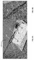
- FIG. 3Ashows an example device that can be used to perform a procedure, according to the principles described herein.
- FIG. 3Bshows an example flow sensor, according to the principles described herein.
- FIGS. 4A and 4Bshow example implementation of an example device, according to the principles described herein.
- FIG. 5shows an example implementation of an electronic circuit and flow sensor, according to the principles described herein.
- FIGS. 6A-6Dshow example flow sensors or example heating elements, according to the principles described herein,
- FIG. 7Ashows another example device, according to the principles described herein.
- FIG. 7Bshows another example device, according to the principles described herein.
- FIGS. 8A and 8Billustrate an operation of the example flow sensors of FIG. 7A-7B , according to the principles described herein.
- FIG. 9shows an example simplified schematic of a differential pre-amplifier, according to the principles described herein.
- FIG. 10shows an example operation of a 3- ⁇ acquisition system, according to the principles described herein.
- FIG. 11illustrates an operation of an example flow sensor, according to the principles described herein.
- FIG. 12shows an example block diagram of an example PID controller coupled to an example flow sensor, according to the principles described herein.
- FIG. 13shows an example of synchronous demodulation, according to the principles described herein.
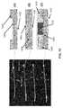
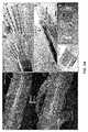
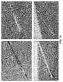
- FIGS. 14A-14Cshow cross-sectional layering structure of various components of an example device, according to the principles described herein.
- FIG. 15shows a flowchart of an example method for performing an example assessment, according to the principles described herein.
- FIG. 16shows example plots of flow measurements, according to the principles described herein.
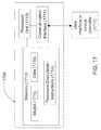
- FIG. 17shows a block diagram of an example system including an assessment module according to the principles described herein.
- FIG. 18Ashows an example flow sensor, according to the principles described herein.
- FIG. 18Bshows example measurements using an example flow sensor, according to the principles described herein.
- FIG. 19shows an example method for performing a procedure, according to the principles described herein.
- FIG. 20shows an example architecture of an illustrative computer system, according to the principles described herein
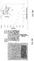
- FIGS. 21A and 21Bshow the results of example measurement using an example device, according to the principles described herein.
- FIGS. 22A and 22Bshow the results of example use of an example device, according to the principles described herein
- FIGS. 23A-23Gillustrates examples of multi-electrode and balloon catheter devices, according to the principles described herein.
- FIGS. 24A-24Dshows examples of catheter devices.
- FIGS. 24E and 24Fshows example forms of sensing, according to the principles described herein.
- FIG. 25shows a non-limiting example of flow sensors on catheters, according to the principles described herein.
- FIG. 26shows an example of flow sensors on a spiral-shaped catheter, according to the principles described herein.
- FIG. 27shows a catheter with bipolar electrodes and metal interconnects, according to the principles described herein.
- FIG. 28A-28Dshows example displays of data or analysis, according to the principles described herein.
- FIG. 29shows example displays of data and plots, according to the principles described herein.
- the term “includes”means includes but is not limited to, the term “including” means including but not limited to.
- the term “based on”means based at least in part on.
- the term “disposed on” or “disposed above”is defined to encompass “at least partially embedded in.”
- any references to “top” surface and “bottom” surfaceare used primarily to indicate relative position, alignment and/or orientation of various elements/components with respect to the substrate and each other, and these terms do not necessarily indicate any particular frame of reference (e.g., a gravitational frame of reference).
- reference to a “bottom” of a substrate or a layerdoes not necessarily require that the indicated surface or layer be facing a ground surface.
- Renal denervation therapycan be used to disrupt the renal nerve through ablation, including through applying energy in the form of RF energy, heating, or cryo (extreme cold) to the nerves. This can be done by inserting a tube or catheter into the groin and guiding the device into the renal artery.
- the renal denervation procedureordinarily is not configured to provide measurement of the efficacy of the process.
- ablation energythat can be applied using a catheter with flow sensing according to the principles described herein include radiofrequency (RF), ultrasound energy, cryoablation, drug-based ablation, alcohol injection, microwave energy ablation, and light-based ablation (laser energy).
- RFradiofrequency
- ultrasound energyultrasound energy
- cryoablationdrug-based ablation
- alcohol injectiondrug-based ablation
- microwave energy ablationand light-based ablation (laser energy).
- an assessment described herein for determining the efficacy of a procedure using flow measurementscan be applied to procedures being performed in other tissue lumen, such as pulmonary veins, coronary arteries, peripheral blood vessels, cardiac lumen, and any other lumen in which flow can be assessed.
- Denervation therapycan be used to disrupt the nerve through ablation, including through applying energy in any of the forms described herein (such as applying RF energy, heating, or cryo (extreme cold) to the nerves), in other systems such as but not limited to the carotid sinus, the carotid body, the vagal nerve, the pulmonary artery, the celiac ganglion, or the bladder trigone.
- energyin any of the forms described herein (such as applying RF energy, heating, or cryo (extreme cold) to the nerves), in other systems such as but not limited to the carotid sinus, the carotid body, the vagal nerve, the pulmonary artery, the celiac ganglion, or the bladder trigone.
- An increase in blood flow in the renal arterycan be used as an indicator of the degree of efficacy of a renal sympathetic denervation (RSDN) procedure.
- RSDNrenal sympathetic denervation
- an indication of an increase in the rate of blood flowcan be considered an indicator that a RSDN procedure is effective in achieving the desired degree and/or amount of denervation in the tissue being targeted.
- Such an indication of the degree of efficacycan be extrapolated to signal an endpoint to the procedure if the flow-rate of blood is approaching the desired level.
- an indication of little or no change in the rate of blood flowcan be considered an indicator that a RSDN procedure is ineffective or marginally effective in achieving the desired degree and/or amount of denervation in the tissue being targeted.
- Such an indication of the degree of efficacycan be extrapolated used in a determination of an expected number of additional procedures to be performed to achieve the desired outcome, or potential changes that could be made to make the RSDN procedure more effective.
- example devices and methodsare described for determining the efficacy of a denervation procedure, or a pacing or other stimulation procedure.
- Example methodsare disclosed that relate to monitoring changes in blood flow rates, or other fluid flow rates, before and/or after the denervation or pacing (or other stimulation) procedure to monitor the stage of the procedure or to determine an endpoint for performance of the procedure.
- a change in flow rate of blood through the tissue lumencan be used to provide an indication of the effectiveness of a procedure performed on the tissue (such as but not limited to the renal artery).
- the procedurecan be any procedure to disrupt the nerve, e.g., through ablation, including through applying energy in the form of RF energy, heating, or cryo (extreme cold) to the nerves.
- An example application of a flow measurement system, apparatus and method described hereinis to provide an indication to a physician that the clinical procedure is successful.
- example devices and methodsare described for use in establishing a clinical endpoint in a procedure in a renal artery or other tissue.
- a measure of blood flow in a renal artery or other tissue prior to the procedure and/or subsequent to the procedurecan be used to provide an indication of an efficacy of a procedure.
- blood flow measurements during a pre-procedure cycle and/or during a post-procedure cyclecan be used to establish a clinical endpoint for the procedure being performed to disrupt the nerve, e.g., through ablation, including through applying energy in the form of RF energy, heating, or cryo (extreme cold) to the nerves.
- Sympathetic nerve activitycontrols blood pressure and flow by virtue of vasoconstriction. Delivery of electrical stimulation to sympathetic nerves can, in turn, be used to stimulate the nerves and cause a modulation in blood flow or other fluid flow. According to the principles described herein, example devices and methods are described for measuring changes in local blood flow and/or pressure during a procedure, such as but not limited to a RSDN procedure.
- novel multifunctional catheter devicesare described that include novel microfabrication technology to build arrays of soft and flexible nanomembrane flow sensing and electrode elements that can be used to provide feedback about renal blood flow, while concurrently delivering pacing energy and/or ablation energy.
- novel design strategies and fabrication techniquesare described that use inorganic semiconductor processes to achieve high performance flexible flow sensor and electrode arrays on catheter devices, such as but not limited to, spiral shaped and balloon catheters that concurrently measure flow and apply RF energy and pacing energy inside a renal artery.
- An example catheter devicecan include at least one pacing electrode.
- a potentialis applied to a portion of tissue proximate to a nerve to stimulate blood flow.
- FIGS. 1A-1Cshow example voltage waveforms that can be used to stimulate the nerves.
- FIG. 2shows a plot of percent changes of renal blood flow as a function of integrated voltage being delivered during pacing.
- FIGS. 1A-1C and FIG. 2demonstrate that blood flow can be changed in the renal artery due to programmed nerve stimulation (during pacing). In an example, such pacing can be performed during a procedure performed according to the principles described herein.
- At least one pacing electrodecan be disposed on an example catheter device described herein to provide an electrical stimulation to tissue, e.g., in a region of a nerve source, prior to, during, and/or following a procedure.
- That procedurecan be any procedure that disrupts the renal nerve through ablation, including through applying energy in the form of RF energy, heating, or cryo (extreme cold) to the nerves.
- Example devices and methodsare described that combine, on a single catheter device, components to perform a procedure on a tissue and components to perform sensing of the flow rate of blood, according to the principles described herein.
- Example devices and methodsare also described that combine on a single catheter device, components to perform nerve stimulation (such as using pacing electrodes) and components to perform sensing of the flow rate of blood, according to the principles described herein.
- nerve stimulationsuch as using pacing electrodes
- an indication of the flow rate of blood based on measurements using the catheter devicecan be used to establish a clinical endpoint during a procedure, including a RSDN procedure.
- FIG. 3Ashows an example device 300 that can be used to perform a procedure according to the principles described herein.
- the example device 300includes an inflatable and/or expandable body 302 , a flow sensor 304 disposed on a portion of the inflatable and/or expandable body 302 , and an electronic circuit 306 disposed on the inflatable and/or expandable body 302 .
- the electronic circuit 306includes a number of components that accommodate expanding of the inflatable and/or expandable body 302 .
- the flow sensor 304is illustrated as being disposed on a distal portion of the inflatable body.
- the flow sensorcan be disposed on or proximate to a proximal portion of the inflatable and/or expandable body.
- the flow sensorcan be a formed as illustrated in FIG. 3B .
- FIG. 3Bshows an example flow sensor 306 ′ that includes a heating element 307 disposed proximate to a temperature sensor 308 .
- the heating element 307 and temperature sensor 308may be disposed on, or encapsulated in, a support 309 .
- Support 309can be formed from a thermally conductive material.
- the heating element 307can be separated from the temperature sensor 308 by a separation “x”.
- the parameter “x”can be about 1 mm, about 2 mm, about 3 mm, about 5 mm, about 8 mm, about 10 mm, about 12 mm, about 18 mm, about 24 mm, about 30 mm or more.
- Temperature sensor 308can be a thermocouple, a resistance temperature detector (RTD) temperature sensor, a junction potential temperature sensor (including sensors that use a voltage measure across a junction as an indicator of temperature), a thermistor, an integrated-circuit temperature sensor (including a LM35-series temperature sensor), or a semiconductor temperature sensor.
- Example flow sensor 306 ′can provide a measure of the flow rate of blood in a tissue lumen based on temperature measurements of the temperature sensor.
- the heating elementis used to maintain the temperature sensor at a specified temperature measurement value. Any fluid flowing past the heating element and temperature sensor can cause some change or fluctuation in the temperature measurement of the temperature sensor.
- the heating elementis configured such that it tried to maintain the temperature sensor at the stable specified temperature reading.
- a change in the fluid flow rate that causes some fluctuation in the reading of the temperature sensorcauses the heating element to increase of decrease its heat output to bring the temperature sensor to its specified reading.
- a faster flow rate of the fluid (e.g., the blood) in the region of the flow sensorcan cause the heating element to increase its heat output.
- a slower flow rate of the fluid (e.g., the blood) in the region of the flow sensorcan cause the heating element to decrease its heat output.
- a change in the operating point of the heating elementcan be used to provide an indication of the flow rate of the fluid measurement of the temperature sensor can be used to provide an indication of the flow rate of fluid proximate to the inflatable and/or expandable body 302 .
- the support 309can be configured to separate the heating element 307 from the fluid by a value “y” as shown in FIG. 3B .
- the parameter “y”can be about 2 mm, about 3 mm, about 5 mm, about 8 mm, about 10 mm, about 12 mm, about 15 mm or more.
- parameters “x” and “y”can be modified to vary the dynamic range of the resulting example flow sensor. For example, “x” can be made larger and “y” can be made smaller to increase the overall range of the example flow sensor. For smaller values of “y”, the heat is able to flow to the region fluid more easily.
- the flow sensorcan be operated over a greater overall range, including range of the operation signal to the heating element.
- the level/magnitude of the signal to the heating elementcan be used to provide an indication of the flow rate of the fluid.
- the greater range of the operation signal to the heating element according to this principlecan provide a larger range of values and a larger data asset of values for use in determining the fluid flow rate.
- the systemcan include a plurality of flow sensors, with two or more of the flow sensors configured with differing values of “x” and “y” between the heating element and temperature sensor of the respective flow sensor.
- the example systempresents flow sensors displaying a variety of measurement ranges.
- the example flow sensors according to the principles described hereincan include a temperature sensor proximate to a thermal ‘radiation’ source.
- heating elementsthat can provide the thermal radiation include any form of heater that can be coupled with a catheter, including a resistive heater or a thermoelectric heater.
- the temperature sensorcan include at least one of a resistance temperature detector (RTD) temperature sensor, a thermocouple, a junction potential temperature sensor (including sensors that use a voltage measure across a junction as an indicator of temperature), a thermistor, an integrated-circuit temperature sensor (including a LM35-series temperature sensor), and a semiconductor temperature sensor.
- RTDresistance temperature detector
- thermocouplea junction potential temperature sensor (including sensors that use a voltage measure across a junction as an indicator of temperature)
- a thermistorincluding sensors that use a voltage measure across a junction as an indicator of temperature
- a thermistorincluding a thermistor
- an integrated-circuit temperature sensorincluding a LM35-series temperature sensor
- semiconductor temperature sensora sensor of known impedance is used.
- Other non-limiting examples of sensors that can be used according to any of the systems and methods described hereininclude vapor deposited gold resistors and ceramic thermistors. In another example, other materials such as foils can be used.
- a calibration standardcan be developed for the flow sensor 306 ′, to correlate the operating point of the heating element to a flow rate.
- training samplescan be used to convert a flow measurement, each training sample being a fluid caused to flow at a specific flow rate.
- the operating point of the flow sensoris obtained for each training sample.
- the flow rate of each training sampleis known (given that it is pre-set for the training samples).
- the amount and/or rate of heating supplied by the heating elementis also known.
- the calibration standardcan be developed to correlate the known heating supplied to the known flow rate to obtain calibration data.
- the example calibration standardcan be used to convert a flow sensor measurement to a flow rate for a fluid having similar properties as the fluid used in the training standard.
- the examples device of FIGS. 3A and 3Bcan further include a flow sensor that is disposed on a portion of a catheter that is coupled to the proximal portion of the inflatable and/or expandable body.
- the electronic circuit 306can include a number of electrodes disposed on the inflatable and/or expandable body 302 .
- the electrodescan be used to perform a procedure according to the principles described herein.
- at least one of the electrodescan be a radiofrequency (RF) electrode that delivers RF energy to a portion of the tissue surface that is proximate to the RF electrode.
- RFradiofrequency
- the delivered RF energyis used to modify the tissue, including to disrupt a renal nerve.
- the device 300can include components to perform a procedure using other modalities.
- the device 300can include components to disrupt the renal nerve, e.g., through ablation, including through applying energy in the form of RF energy, heating, or cryo (extreme cold) to the nerves.
- the electronic circuit 306 of device 300can include at least one pacing electrode.
- the pacing electrodecan be implemented to deliver an electrical stimulation to a portion of a tissue (such as but not limited to a renal artery) proximate to the pacing electrode.
- the pacing electrodecan be used to stimulate nerve at different stages of a procedure.
- the electrical stimulation from the pacing electrode(s)can be applied to the portion of the tissue to stimulate nerves prior to delivery of an energy to disrupt the nerves, such as but not limited to through ablation, including through applying energy in the form of RF energy, heating, or cryo (extreme cold) to the nerves.
- the electrical stimulation from the pacing electrode(s)can be applied to the portion of the tissue to stimulate nerves subsequent to delivery of an energy to disrupt the nerves, such as but not limited to through ablation, including through applying energy in the form of RF energy, heating, or cryo (extreme cold) to the nerves.
- an energy to disrupt the nervessuch as but not limited to through ablation, including through applying energy in the form of RF energy, heating, or cryo (extreme cold) to the nerves.
- the electronic circuit 306can also include temperature sensors, each temperature being disposed proximate to an electrode of the electronic circuit 306 .
- the device 300can include one or more other components disposed on the inflatable and/or expandable body such as, but not limited to, a pacing electrode, a light-emitting device, a contact sensor, an image detector, a pressure sensor, a biological activity sensors, a temperature sensor, or any combination thereof.
- a pacing electrodea light-emitting device
- a contact sensora contact sensor
- an image detectora pressure sensor
- a biological activity sensorsa temperature sensor, or any combination thereof.
- FIGS. 4A and 4Bshow a non-limiting example implementation of an example device 400 .
- the example device 400includes an inflatable and/or expandable body 402 , a flow sensor 404 disposed on a portion of the inflatable and/or expandable body 402 , and an electronic circuit 406 disposed on the inflatable and/or expandable body 402 .
- the electronic circuit 406includes a number of components that accommodate expanding of the inflatable and/or expandable body 402 .
- the flow sensor 404can be being disposed on a distal portion of the inflatable and/or expandable body 402 .
- a portion of the distal region of the expandable and/or inflatable structurecan be extended to form a protrusion.
- the flow sensor 404can be mounted on the protrusion.
- the flow sensor 404can be disposed on or proximate to a proximal portion of the inflatable and/or expandable body.
- the flow sensor 404can be a formed as including a heating element 407 disposed proximate to a temperature sensor 408 .
- the heating element 407can be separated from the temperature sensor 408 by about 1 mm or about 2 mm.
- the heating element 407can be a temperature-controlled heating element.
- the temperature sensor 408can be a thermistor.
- the electronic circuitcan include a number of electrodes 410 disposed on the inflatable and/or expandable body 402 .
- the electrodescan be used to perform a procedure according to the principles described herein.
- at least one of the electrodes 410can be a radiofrequency (RF) electrode that delivers RF energy to a portion of the tissue surface that is proximate to the RF electrode.
- RFradiofrequency
- the delivered RF energyis used to modify the tissue, including to disrupt a renal nerve.
- the electronic circuit 406 of the example device 400can include stretchable interconnects 412 disposed on the surface of the inflatable and/or expandable body 402 .
- the stretchable interconnectscan be used to electrically couple at least one of the plurality of electrodes 410 to an external circuit.
- the electronic circuit 406 of the example device 400can also include a main bus 414 .
- the stretchable interconnects 412electrically couple the electrodes 410 to the man bus 414 .
- the main bus 414can extend beyond the inflatable and/or expandable body 402 to facilitate electrical coupling of the electrodes 410 to an external circuit.
- the at least one of the electrodes 410 of electronic circuit 406 of device 400can be a pacing electrode.
- the pacing electrodecan be implemented to deliver an electrical stimulation to a portion of a tissue (such as but not limited to a renal artery) proximate to the pacing electrode.
- the pacing electrodecan be used to stimulate nerve at different stages of a procedure.
- the electrical stimulation from the pacing electrode(s)can be applied to the portion of the tissue to stimulate nerves prior to delivery of an energy to disrupt the nerves, such as but not limited to through ablation, including through applying energy in the form of RF energy, heating, or cryo (extreme cold) to the nerves.
- the electrical stimulation from the pacing electrode(s)can be applied to the portion of the tissue to stimulate nerves subsequent to delivery of an energy to disrupt the nerves, such as but not limited to through ablation, including through applying energy in the form of RF energy, heating, or cryo (extreme cold) to the nerves.
- an energy to disrupt the nervessuch as but not limited to through ablation, including through applying energy in the form of RF energy, heating, or cryo (extreme cold) to the nerves.
- the device 400can include components to perform a procedure using other modalities.
- the device 400can include components to disrupt the renal nerve, e.g., through ablation, including through applying energy in the form of RF energy, heating, or cryo (extreme cold) to the nerves.
- the device 400can include one or more other components disposed on the inflatable and/or expandable body such as, but not limited to, a pacing electrode, a light-emitting device, a contact sensor, an image detector, a pressure sensor, a biological activity sensors, a temperature sensor, or any combination thereof.
- a pacing electrodea light-emitting device
- a contact sensora contact sensor
- an image detectora pressure sensor
- a biological activity sensorsa temperature sensor, or any combination thereof.
- the device 400can also include temperature sensors, each temperature being disposed proximate to an electrode 410 of the electronic circuit 406 .
- FIG. 5shows a non-limiting example implementation of an electronic circuit 506 and flow sensor 504 that can be disposed on a catheter and extend to a shaft of an example device according to the principles described herein.
- the electronic circuit 506includes a number of electrodes 510 .
- the electrodes 510can be conformable electrodes that conform to the surface of the inflatable and/or expandable body.
- the flow sensor 504includes a heating element 507 disposed proximate to a temperature sensor 808 .
- the heating element 507can be a temperature-controlled heating element.
- the temperature sensor 508can be a thermistor.
- At least one of the electrodes 510can be a radiofrequency (RF) electrode that delivers RF energy to a portion of the tissue surface that is proximate to the RF electrode. According to the principles described herein, the delivered RF energy is used to modify the tissue, including to disrupt a renal nerve. At least one of the electrodes 510 can be a pacing electrode that delivers an electrical stimulation to a nerve, as described herein.
- RFradiofrequency
- the electronic circuit 506includes stretchable interconnects 512 disposed on the surface of the inflatable and/or expandable body.
- the stretchable interconnects 512can be used to electrically couple at least one of the plurality of electrodes 510 to an external circuit.
- the electronic circuit 506also includes a main bus 514 .
- the stretchable interconnects 512electrically couple the electrodes 510 to the main bus 514 .
- the main bus 514includes connection pads 516 that facilitate electrical coupling of the electrodes 510 to an external circuit.
- FIG. 6Ashows a portion of an example device 600 that can be used to perform a procedure according to the principles described herein.
- the example device 300includes an elongated member 602 , and a flow sensor 604 disposed on a distal portion of the elongated member 602 .
- the flow sensor 604is illustrated as being disposed on a distal portion of the elongated member.
- the flow sensorcan be disposed on or proximate to a proximal portion of the elongated member or on a proximal or distal portion of an inflatable and/or expandable body that is coupled to the elongated member.
- the flow sensorcan be formed as illustrated in FIG. 6A , and includes a heating element 606 and a temperature sensor 608 .
- the heating element 606includes a cavity 607 . As shown in FIG. 6A , at least a portion of the temperature sensor 608 is housed in a portion of the cavity 607 .
- the heating element 606can be used to heat an area proximate to the elongated member 602 .
- a temperature measurement of the temperature sensor 608can be used to provide an indication of the flow rate of a fluid proximate to the flow sensor 604 . For example, if the fluid has a higher flow rate and wicks away heat from the area proximate to the heating element, the temperature sensor can record a different measurement than obtained if the fluid flow rate is lower.
- the heating elementis used to maintain the temperature sensor at a specified temperature measurement value. Any fluid flowing past the heating element and temperature sensor can cause some change or fluctuation in the temperature measurement of the temperature sensor.
- the heating elementis configured such that it tries to maintain the temperature sensor at the stable specified temperature reading. A change in the fluid flow rate that causes some fluctuation in the reading of the temperature sensor causes the heating element to increase of decrease its heat output to bring the temperature sensor to its specified reading. A faster flow rate of the fluid (e.g., the blood) in the region of the flow sensor can cause the heating element to increase its heat output. A slower flow rate of the fluid (e.g., the blood) in the region of the flow sensor can cause the heating element to decrease its heat output.
- a change in the operating point of the heating elementcan be used to provide an indication of the flow rate of the fluid measurement of the temperature sensor can be used to provide an indication of the flow rate of fluid proximate to the inflatable and/or expandable body 302 .
- temperature sensor 608can be a thermocouple, a resistance temperature detector (RTD) temperature sensor, a junction potential temperature sensor (including sensors that use a voltage measure across a junction as an indicator of temperature), a thermistor, an integrated-circuit temperature sensor (including a LM35-series temperature sensor), or a semiconductor temperature sensor.
- RTDresistance temperature detector
- junction potential temperature sensorincluding sensors that use a voltage measure across a junction as an indicator of temperature
- thermistorincluding a thermistor
- an integrated-circuit temperature sensorincluding a LM35-series temperature sensor
- semiconductor temperature sensora sensor of known impedance is used.
- Other non-limiting examples of sensorsthat can be used according to any of the systems and methods described herein include vapor deposited gold resistors and ceramic thermistors. In another example, other materials such as foils can be used.
- the example flow sensors according to the principles described in connection with FIG. 6Acan include any type of a thermal ‘radiation’ source.
- Non-limiting examples of heating elements that can be implemented to provide the thermal radiationinclude any form of heater that can be coupled with an elongated member and be configured to have a cavity.
- the heating elementcan be, but is not limited to, a resistive heater or a thermoelectric heater.
- FIG. 6Bshows an implementation 620 of an example flow sensor 624 according to the principles of FIG. 6A .
- the example flow sensor 624includes a heating element 626 and a temperature sensor 628 .
- the heating element 626is formed as a spiral, helical, or other coiled resistive wire with a hollow core that provides a cavity.
- the resistive wirecan be formed from a high resistivity electrically material to facilitate higher power dissipation.
- at least a portion of the temperature sensor 628is housed in a portion of the cavity.
- the heating element 626 and the temperature sensor 628can be at least partially encapsulated in a thermally conductive encapsulant.
- the heating element 626can be used to heat an area proximate to an elongated member that the flow sensor is coupled to.
- a temperature measurement of the temperature sensor 628can be used to provide an indication of the flow rate of a fluid proximate to the flow sensor 624 .
- FIG. 6Cshows another implementation 630 of an example flow sensor according to the principles of FIG. 6A .
- the example flow sensorincludes a heating element 636 and a temperature sensor (not shown).
- the heating element 636is formed as a patterned thin-film of a resistive material 631 on a flexible and/or stretchable substrate 633 .
- the thin-filmis patterned in a boustrophedonic pattern.
- the heating element 636can be rolled into a more compact form factor, with at least a portion formed with a hollow core that provides a cavity.
- the resistive wirecan be formed from a high resistivity electrically conductive material to facilitate higher power dissipation. Similarly to as described in connection with the flow sensor of FIGS.
- the heating element 636can be used to heat an area proximate to an elongated member that the flow sensor is coupled to.
- a temperature measurement of the temperature sensor disposed at least partially in the cavitycan be used to provide an indication of the flow rate of a fluid proximate to the flow sensor 634 .
- FIG. 6Cshows another implementation 630 of an example flow sensor according to the principles of FIG. 6A .
- the example flow sensorincludes a heating element 636 and a temperature sensor (not shown).
- the heating element 636is formed as a patterned thin-film of a resistive material 631 on a flexible and/or stretchable substrate 633 .
- the thin-filmis patterned in a boustrophedonic pattern.
- other linear patternscan be used.
- the heating element 636can be formed into a compact form factor, with at least a portion formed with a cavity 637 .
- the thin-filmcan be formed from a high resistivity electrically conductive material to facilitate higher power dissipation. Similarly to as described in connection with the flow sensor of FIGS.
- the heating element 636can be used to heat an area proximate to an elongated member that the flow sensor is coupled to.
- a temperature measurement of the temperature sensor disposed at least partially in the cavitycan be used to provide an indication of the flow rate of a fluid proximate to the flow sensor.
- FIG. 6Dshows another implementation 640 of an example flow sensor coupled to a portion of an elongated member 642 according to the principles of FIG. 6A .
- the example flow sensorincludes a heating element 646 and a temperature sensor (not shown).
- the heating element 646is formed as a patterned thin-film of a resistive material 641 on a flexible and/or stretchable substrate 643 .
- the thin-filmcan be patterned in a stretchable pattern.
- the stretchable patternallows more bending of the elongated member while compensating for surface strain.
- FIG. 6Dshows a serpentine pattern
- the stretchable patternmay be other stretchable pattern, including a zig-zag pattern, a wavy pattern or a rippled pattern.
- the heating element 646can be formed into a compact form factor, with at least a portion formed with a cavity.
- the thin-filmcan be formed from a high resistivity electrically conductive material to facilitate higher power dissipation.
- the heating element 646can be used to heat an area proximate to an elongated member that the flow sensor is coupled to.
- a temperature measurement of the temperature sensor disposed at least partially in the cavitycan be used to provide an indication of the flow rate of a fluid proximate to the flow sensor.
- FIG. 7Ashows another example device 700 that can be used to perform a procedure according to the principles described herein.
- the example device 700includes an inflatable and/or expandable body 702 , a pair of flow sensors 704 - a and 704 - b , and an electronic circuit 706 disposed on the inflatable and/or expandable body 702 .
- the device 700is coupled to a distal portion of a shaft 708 .
- the electronic circuit 706includes a number of components that accommodate expanding of the inflatable and/or expandable body 702 .
- one of the flow sensor 704 - ais shown to be disposed on a proximal portion of the inflatable body.
- the other flow sensor(reference flow sensor 704 - b ) is shown to be disposed on a portion of shaft 708 at some distance away from the inflatable and/or expandable body 702 .
- the flow ratecan be measured based on comparison of the measurement of the pair of flow sensors 706 - a and 706 - b .
- the flow ratecan be measured based on comparison of voltage measurements of the pair of flow sensors 706 - a and 706 - b.
- FIG. 7Bshows another example device 700 ′ that can be used to perform a procedure according to the principles described herein.
- Example device 700 ′includes an inflatable and/or expandable body 702 , a pair of flow sensors 704 - a and 704 - b , an electronic circuit 706 disposed on the inflatable and/or expandable body 702 , and a shaft 708 , the same components as example device 700 , and they are not repeated.
- Example device 700 ′also includes a shaft 710 that can be disposed over reference electrode 704 - b during a procedure or a flow measurement. The example device 710 also can be retracted to such an extent that reference flow sensor 704 - b is exposed.
- the reference sensorcan be positioned on the shaft at a location that can be covered by a sheath.
- FIG. 7Bshows a non-limiting example of a catheter device that includes a sheath member that can be positioned to cover at least a portion of the reference sensor.
- this distancecan be determined as greater than or equal to about 10 cm away from the proximal end of the balloon. In another example implementation, this distance can be determined as less than about 10 cm away from the proximal end of the balloon.
- the reference flow sensor 704 - bcan be positioned at a distance away on the shaft of the catheter that is at least about 5 cm, at least about 8 cm, at least about 10 cm, at least about 13 cm, at least about 15 cm or more.
- a sheathcan be included and used to guide, introduce and steer the catheter.
- the sheathcan be a member that surrounds at least a portion of the circumference of the shaft of the catheter and/or can be co-axial with the shaft of the catheter.
- the reference sensorcan be maintained under the sheath.
- the sheathcan be configured to provide a stable known environment and provide a chamber that can include blood in the absence of flow.
- the bloodcan be maintained at body temperature but does not flow, thereby providing a useful comparison in proximity of the reference sensors.
- the measurement performed using the reference sensor in this environment of blood that is not flowingcan serve as a reference for comparison to the renal artery sensor.
- the internal shaft near the reference sensorcan include surface features in the form of bumps or tracks that provide channels for the blood.
- the bloodforms an insulating layer on the reference sensor, allowing a reference quiescent blood temperature to be measured.
- the surface featurescan be designed and configured to allow blood to circulate as freely and prevent the shaft from making contact with the sheath in that area.
- the shaftmay include one or more spacers (also referred to as protuberances) to maintain the shaft spaced apart from a portion of the surface of the sheath. The spacing apart of the shaft from the sheath helps to maintain a static layer of blood static between the sheath and the shaft.
- FIGS. 8A and 8Billustrate an operation of the flow sensors of FIG. 7A-7B .
- FIG. 8Ashows an example device 800 that includes an inflatable and/or expandable body 802 , a pair of flow sensors 804 - a and 804 - b , an electronic circuit 806 disposed on the inflatable and/or expandable body 802 , a shaft 808 and a sheath 810 .
- Flow sensor 804 - bis coupled to the shaft and covered by the sheath 810 .
- the inflatable or expandable structurecan be deflated or retracted at the time of flow sensor measurement.
- the method in connection with FIGS. 8A and 8Bcan be used to resolve small changes in temperature in the body.
- An example system, apparatus and method according to the principles described hereincan be used to measure the signal of interest in connection with a procedure and reject information that does not relate to the signal of interest, thereby increasing resolution and reducing the requirements for expensive signal processing.
- An example system, apparatus and method according to the principles described hereincan be used to measure differential flow, such as described in connection with FIGS. 8A and 8B .
- two (or more) sensorsare used to measure flow via a change in flow sensor operating point.
- at least one reference sensorcan be placed on the shaft of a catheter used to perform a measurement described herein.
- the non-limiting example cathetercan include one or more renal artery flow sensors and/or one or more other sensors, including one or more ablation components and/or one or more pacing electrodes.
- the reference sensorcan be disposed about the inflatable or expandable member of the catheter, such as but not limited to a balloon, an expandable mesh, or a deployable netting.
- the reference sensorcan be disposed at a sufficient separation distance away from the proximal end of the balloon so that the reference sensor is covered by the sheath of the catheter when it is proximate to the tissue of the body.
- One or more renal artery sensorscan be positioned at or near the proximal end of the balloon. Each measurement taken can be compared or displayed in reference to a measurement of the reference sensor.
- each flow sensorincluding any reference sensor, can be excited using the same controlled current source.
- each sensorcan be measured using an instrumentation amplifier.
- FIG. 9shows a non-limiting example simplified schematic of a differential pre-amplifier that can be used to measure differences in voltages.
- the example differential pre-amplifier circuitrycan be implemented to compare measurements of flow sensors according to the principles of FIGS. 8A-8B .
- the flow sensorscan include thermistors.
- the flow sensorscan include at least one of a resistance temperature detector (RTD) temperature sensor, a thermocouple, a junction potential temperature sensor (including sensors that use a voltage measure across a junction as an indicator of temperature), an integrated-circuit temperature sensor (including a LM35-series temperature sensor), and a semiconductor temperature sensor.
- RTDresistance temperature detector
- thermocouplea junction potential temperature sensor (including sensors that use a voltage measure across a junction as an indicator of temperature)
- an integrated-circuit temperature sensorincluding a LM35-series temperature sensor
- a semiconductor temperature sensora sensor of known impedance is used.
- Other non-limiting examples of sensors that can be used according to any of the systems and methods described hereininclude vapor deposited gold resistors and ceramic thermistors. In another example, other materials such as foils can be used.
- the difference in the voltagecan be measured between the flow sensors (such as but not limited to the thermistor) that are driven by an excitation current.
- Signal Cis the difference between the signal from the flow sensor proximate to the inflatable and/or expandable body (renal flow sensor measurement—signal A) and the signal from the reference flow sensor (reference flow sensor measurement—signal B).
- the instrumentation amplifierscan be used to reject common-mode signals, thereby providing a higher fidelity signal.
- an apparatus or system described hereincan include thermistors that are well matched (used as the flow sensors in this example).
- the absolute values of the thermistor measurementscan be used.
- a benefit of measuring a reference thermistor and renal artery thermistorcan be improvement of the dynamic range by measuring the difference of the values between the sensors as compared to using the absolute values. Limiting the measurements between the reference and the renal artery sensor can facilitate improvement of the dynamic range of the measurements.
- the flow sensorsare of known impedances, and application of an excitation current using the flow sensors creates a voltage that is measured using instrumentation amplifiers.
- the amplifiersare used to measure a voltage correlating to a flow rate. Changes in blood flow can result in a change in operating set point in at least one of the flow sensors.
- the flow ratecan be quantified. Through this comparison, the instrument voltage in the absence of flow also can be removed.
- the value of voltage measured using the reference sensoris subtracted from the renal artery sensor voltage to provide an indication of the instrument voltage in the absence of flow.
- a reference flow sensoris surrounded by a sheath
- blood in the sheathis physically static. That is, it is not flowing and remains at body temperature.
- Blood in the renal arteryis also at body temperature but flows at some rate (desired to be measured).
- one or more flow sensorscan be calibrated.
- An offset value between the flow sensors disposed proximate to the inflatable and/or expandable body and the reference flow sensor(s)can be eliminated by placing the catheter in a known temperature and flow rate, and measuring the difference between the two sets of sensors. The measurement can be performed and/or the offset value can be derived at the time of manufacture of the catheter and/or time of assembly of the flow sensors with the inflatable and/or expandable body of the catheter.
- the offset valuecan be stored and/or indicated as a written value, or a barcode or other form of identification (ID).
- an integrated circuit or memory device or other meanscan be used to provide this value and ID to a console that is in communication with the catheter (including with the flow sensors disposed on or proximate to the inflatable and/or expandable body).
- This offset valuecan be programmed into the catheter.
- the consolecan use the offset value to compensate for an offset in the measurements when calculating flow.
- Detecting a change in reading of a thermistorcan provide an indication of the rate of fluid flow. Detecting flow rate change in the renal artery can require high-resolution measurement.
- the differential measurement described in connection with FIGS. 7A-7B and 8can be used in conjunction with other methods, such as peak-to-peak measurements, synchronous-demodulation (lock-in), and three omega (3 ⁇ ) methods.
- the differential measurementcan be used to measure peak-to-peak output, or it can be input into a lock-in amplifier or 3 ⁇ acquisition system as shown in FIG. 10 .
- the 3 ⁇ methodcan be implemented using a micro-fabricated metal pattern acting as a resistive heater.
- An alternating current (AC) voltage signalenergizes the resistive element at a frequency w.
- the periodic heatinggenerates oscillations in the electrical resistance of the metal line at a frequency of 2 ⁇ . In turn, this leads to a third harmonic (3 ⁇ ) in the voltage signal.
- the third harmonicis used according to an example implementation to determine the magnitude of the temperature oscillations.
- the temperature oscillationscan be used to provide an indication of the flow rate of a fluid.
- the frequency dependence of these temperature oscillationscan be used to derive the thermal properties of the specimen (e.g., the fluid).
- the data indicative of the thermal properties of the specimencan be used to derive data indicative of the flow rate of the fluid.
- the flow sensor(including the 3-omega sensor) can be disposed on the example device such that the flow sensor is disposed within a mid-point of a tissue lumen when the example device is disposed within the lumen.
- the mid-point of the lumen in tissuecan be the location of maximum flow velocity).
- the central positioning of the flow sensorcan facilitate more accurate measured of fluid flow rate by sampling the area of maximum flow.
- FIG. 11illustrates an example device that is comprised of a flow sensor 1154 disposed on a distal portion of a rod catheter or guidewire 1152 , a reference temperature sensor 1156 disposed on a proximal portion of the rod catheter or guidewire 1152 , and a sheath 1158 .
- Reference temperature sensor 1156is coupled to the shaft and may be covered by the sheath 1158 or may remain uncovered.
- the systemcan be operated such that a specified difference can be maintained between the value of the temperature measurement of the reference temperature sensor 1156 and the value of the temperature measurement of the temperature sensor of the flow sensor 1154 .
- the temperature differencecan be maintained at a value of temperature difference of about 1.5° C., about 2.0° C., about 2.5° C., about 3.0° C., about 3.5° C., about 4.0° C., or about 4.5° C. While the examples of FIGS. 7A through 8B are described as having a reference flow sensor ( 704 - b or 810 ), each system can be operated as described in connection with FIG. 11 , but with the reference flow sensor replaced with a reference temperature sensor.
- a devicecan be implemented to performing a medical treatment procedure on a tissue as follows.
- the example deviceincludes an elongated member, a flow sensor disposed proximate to a distal portion of the elongated member, and a reference temperature sensor disposed proximate to a proximal portion of the elongated member.
- the flow sensor and the reference temperature sensorare in communication with a control module.
- the control moduleis used to maintain a temperature difference between the measurement of the reference temperature sensor and the measurement of the temperature sensor of the flow sensor.
- control modulecan be used to monitor the temperature measurement(s) of the reference temperature sensor and/or the temperature measurement(s) of the temperature sensor of the flow sensor at various stages of the procedure being performed. Based on the monitoring, the control module can generate signals to the heating element to cause it to emit heat or discontinue emitting heat, such that that the temperature difference is maintained.
- the signal(s) applied to the heating elementcan be stored to a memory, transmitted using a communication interface or a communication protocol, and/or read out to a user interface (such as a display).
- the temperature differencecan be maintained as a constant temperature difference or a time-varying temperature difference.
- a constant temperature differencecan be maintained at about 1.5° C., about 2.0° C., about 2.5° C., about 3.0° C., about 3.5° C., about 4.0° C., or about 4.5° C.
- the control moduleincludes a proportional-integral-derivative (PID) controller.
- FIG. 12shows an example control system for implementing a PID controller control loop. As shown in FIG. 11 , the PID controller receives as input a voltage signal 1202 from the temperature sensor of the flow sensor and a voltage signal 1204 from the reference temperature sensor. At 1206 , the PID controller applies an algorithm and associated method to determine the three-term controls: the proportional (P), the integral (I), and the derivative (D) values. Based on these computations, the PID controller determines the error or degree of deviation of the measured signals from the temperature sensors from the expected values that would maintain the desired temperature difference between them.
- PIDproportional-integral-derivative
- the PID controllerapplies a heating element control algorithm (and associated method) to the combination of P, I, and D values to determine a signal to send to a voltage controlled current source 1210 to the heating element 1212 .
- the signal sent to the voltage controlled current source 1210causes adjustments to the power to the heating element, to cause it to emit heat, or discontinue emitting heat. That is, applying the PID controller involves comparing the value of the temperature measurement of the reference temperature sensor to the temperature measurement of the temperature sensor of the flow sensor, determining a signal, e.g., a PID correction signal, based on the comparison, and using the control module to determine the signal to the heating element based on the PID correction signal.
- the systemcan minimize the deviation of the measured signals from the temperature sensors from the expected values that would maintain the desired temperature difference between them.
- the systemcan include hardware to generate a sinusoidal current with a fixed frequency but varying amplitude for the heating element.
- control modulecan be configured to maintain a constant temperature difference, such as but not limited to about 2° C., between the reference temperature sensor and the temperature measured at the temperature sensor of the flow sensor.
- the heating elementcan be powered to heats the temperature sensor of the flow sensor (e.g., a thermistor) to about 39° C.
- the use of the control module as described hereinmaintains this temperature difference, such that the reference temperature sensor is maintained at a constant temperature difference of about 2° C., i.e., at about 37° C.
- the signal applied to the heating elementcan be stored to a memory, transmitted using a communication interface, and/or read out to a user interface (such as a display).
- control modulecan be configured to maintain a constant temperature difference while the example device is being used during a procedure, e.g., nerve stimulation, ablation or other denervation procedure. If fluid flow rate increases during the procedure, the increased fluid flow rate removes heat from the region of the flow sensor (the coupled heating element and temperature sensor). The control module determines from the control loop that the temperature difference is deviating from the desired value (e.g., a temperature difference falling below about 2° C.). The control module generates a signal to cause the heating element to emit heat, to return the temperature difference to the desired value (e.g., a value of about 2° C.).
- desired valuee.g., a temperature difference falling below about 2° C.
- the signal applied to the heating elementcan be stored to a memory, transmitted using a communication interface, and/or read out to a user interface (such as a display). In this case, the signal could show an increase, since as it sending controls to cause the heating element to emit heat.
- the decreased fluid flow rateremoves less heat from the region of the flow sensor (the coupled heating element and temperature sensor).
- the control moduledetermines from the control loop that the temperature difference is deviating from the desired value (e.g., a temperature difference may be increasing to above about 2° C.).
- the control modulegenerates a signal to cause the heating element to cease emitting heat, to return the temperature difference to the desired value (e.g., a value of about 2° C.).
- the signal applied to the heating elementcan be stored to a memory, transmitted using a communication interface, and/or read out to a user interface (such as a display). In this case, the signal could show a decrease, since as it sending controls to cause the heating element to cease emitting heat.
- the differential temperature measurementcan be performed using two or more temperature sensors, including a reference temperature sensor that is not coupled to a heating element; and a sense temperature sensor that is coupled to and heated by a heating element (forming a flow sensor).
- the temperature sensor coupled with the heating elementmay be disposed on a distal portion or a proximal portion of an elongated member such as but not limited to a rod catheter or a guidewire, or a distal portion or a proximal portion of an elongated member that includes an inflatable and/or expandable body.
- the reference temperature sensorcan be disposed at least about 0.5 cm, at least about 1 cm, at least about 1.5 cm, or at least about 2 cm or more distance spaced apart from the flow sensor.
- a devicecan include two or more flow sensors, including a plurality of flow sensors.
- the two or more flow sensorscan be coupled via the control module to a single reference temperature sensor, or each flow sensor may be coupled to a respective reference temperature sensor.
- the signal to the heating elementcan be a time-varying voltage signal.
- the excitation of the heating element and the temperature sensor of the flow sensorcan be using an AC frequency greater than the inverse of tissue response time.
- signals at AC frequenciesranging from about 1 kHz to about 100 kHz can be used to drive the flow sensor to reduce the risk of accidentally causing fibrillation. Operating at frequencies in this range also allows for higher current leakage.
- the signal to the heating elementcan be a voltage signal, a current signal, a digital signal, or any other signal that transmits instructions to cause the heater to heat at a desired temperature to maintain the desired temperature difference.
- the signalcan be read out and/or plotted, stored to a memory, or otherwise communicated or transmitted.
- control signalcan be mapped to a flow rate through the analysis of multiple data runs and measurements, to generate a standard or other calibration chart that relates a value of a control signal to the physiological flow rate.
- novel signal processing algorithms and associated methods, and control modulesare provided for sensing and/or quantifying fluid flow rates.
- FIG. 13shows an example demodulation that can be implemented to extract the signal to the heating element from the noise in the signal.
- processor-executable instructions that create a phase-locked loop (PLL)can be applied with a synchronous demodulation method to reject noise and derive the signal.
- At least one phase-locked loopcan be used to lock-in the sensing signal to the control signal, and the sensing signal to the heater signal for the synchronous-demodulation. Since the same frequency is used to demodulate the data, the desired signal is extracted as a DC signal (representing the amplitude modulation).
- the synchronous demodulationprovides a narrow band filter to reject noise injected by the environment of the device, which can interfere with the desired signal.
- systems and methods hereinprovide a way to determine a clinical endpoint during a procedure, such as but not limited to a carotid sinus denervation, a carotid body disruption, a vagus nerve stimulation, a pulmonary artery denervation, a celiac ganglion disruption, a bladder trigone ablation, or a renal denervation procedure.
- any system or device according to the principles described hereinmay be entirely or at least partially encapsulated by an encapsulating material, such as a polymer material (including any of the polymer materials described herein).
- An encapsulating materialcan be any material that can be used to laminate, planarize, or encase at least one component of a system or device described herein, including any electronic or other type of component.
- a method of fabricating any system or device according to the principles described hereincan further include encapsulating the system or device.
- an encapsulating materialcan be disposed over, or otherwise applied to, an device that includes an inflatable and/or expandable body and the electronic circuit or a plurality of electrodes.
- a polyurethanecan be used as the encapsulating material.
- the encapsulating materialcan be the same material as the material for the inflatable and/or expandable body. Encapsulating any portion of the systems or device described herein can be useful to enhance the mechanical stability and robustness of the system or device, or to maintain electronic performance of the electronic components of the system or device against a stress or strain applied to the system or device during use.
- the encapsulating materialcan be formed from any material having elastic properties.
- the encapsulatingcan be formed from a polymer or polymeric material.
- Non-limiting examples of applicable polymers or polymeric materialsinclude, but are not limited to, a polyimide, a polyethylene terephthalate (PET), a silicone, or a polyeurethane.
- Non-limiting examples of applicable polymers or polymeric materialsinclude plastics, elastomers, thermoplastic elastomers, elastoplastics, thermostats, thermoplastics, acrylates, acetal polymers, biodegradable polymers, cellulosic polymers, fluoropolymers, nylons, polyacrylonitrile polymers, polyamide-imide polymers, polyarylates, polybenzimidazole, polybutylene, polycarbonate, polyesters, polyetherimide, polyethylene, polyethylene copolymers and modified polyethylenes, polyketones, poly(methyl methacrylate, polymethylpentene, polyphenylene oxides and polyphenylene sulfides, polyphthalamide, polypropylene, polyurethanes, styrenic resins, sulphone based resins, vinyl-based resins, or any combinations of these materials.
- a polymer or polymeric material hereincan be a DYMAX® polymer (Dymax Corporation, Torrington, Conn.). or other UV curable polymer, or a silicone such as but not limited to ECOFLEX® (BASF, Florham Park, N.J.).
- the encapsulantshould be biocompatible.
- the stretchable interconnectscan be embedded in a polyimide that also acts as a mechanical reinforcement.
- any of the systems or device according to the principles hereincan be disposed on the inflatable and/or expandable body such that a functional layer of the system or device lies at a neutral mechanical plane (NMP) or neutral mechanical surface (NMS) of the system or device.
- the NMP or NMSlies at the position through the thickness of the device layers for the system or device where any applied strains are minimized or substantially zero.
- the functional layer of a system or device according to the principles described hereinincludes the plurality of sensing elements, the coupling bus, and/or the stretchable electronic system that includes the flexible annular interconnect and the plurality of electrodes.
- the location of the NMP or NMScan be changed relative to the layer structure of the system or device through introduction of materials that aid in strain isolation in various layers of the system or device.
- polymer materials described hereincan be introduced to serve as strain isolation materials.
- the encapsulating material described hereinabovecan be used to position the NMP or NMS, e.g., by varying the encapsulating material type and/or layer thickness.
- the thickness of encapsulating material disposed over the functional layers described hereinmay be modified (i.e., decreased or increased) to depress the functional layer relative to the overall system or device thickness, which can vary the position of the NMP or NMS relative to the functional layer.
- the type of encapsulatingincluding any differences in the elastic (Young's) modulus of the encapsulating material.
- At least a partial intermediate layer of a material capable of providing strain isolationcan be disposed between the functional layer and the inflatable and/or expandable body to position the NMP or NMS relative to the functional layer.
- the intermediate layercan be formed from any of the polymer materials described herein, aerogel materials or any other material with applicable elastic mechanical properties.
- the NMP or NMScan be positioned proximate to, coincident with or adjacent to a layer of the system or device that includes the strain-sensitive component, such as but not limited to the functional layer.
- the layercan be considered “strain-sensitive” if it is prone to fractures or its performance can be otherwise impaired in response to a level of applied strain.
- the position of the NMP or NMSmay still provide a mechanical benefit to the strain-sensitive component, such as substantially lowering the strain that would otherwise be exerted on the strain-sensitive component in the absence of strain isolation layers.
- the NMS or NMP layeris considered proximate to the strain-sensitive component that provides at least 10%, 20%, 50% or 75% reduction in strain in the strain-sensitive component for a given applied strain, e.g., where the inflatable body is inflated.
- the encapsulating material and/or the intermediate layer materialmay be disposed at positions coincident with the strain-sensitive component, including in the functional layer.
- portions of the encapsulating material and/or the intermediate layer materialmay be interspersed with the strain-sensitive component, including at positions within the functional layer.
- portions of the stretchable interconnects, the electrodes and portions of the main buscan be formed from a conductive material.
- the conductive materialcan be but is not limited to a metal, a metal alloy, a conductive polymer, or other conductive material.
- the metal or metal alloy of the coatingmay include but is not limited to aluminum, stainless steel, or a transition metal (including copper, silver, gold, platinum, zinc, nickel, titanium, chromium, or palladium, or any combination thereof) and any applicable metal alloy, including alloys with carbon.
- suitable conductive materialsmay include a semiconductor-based conductive material, including a silicon-based conductive material, indium tin oxide or other transparent conductive oxide, or Group III-IV conductor (including GaAs).
- the semiconductor-based conductive materialcan be doped.
- the stretchable interconnectscan have a thickness of about 0.1 ⁇ m, about 0.3 ⁇ m, about 0.5 ⁇ m, about 0.8 ⁇ m, about 1 ⁇ m, about 1.5 ⁇ m, about 2 ⁇ m or greater.
- the buffer structure and/or flexible basecan have a thickness of about 5 ⁇ m, about 7.5 ⁇ m, about 9 ⁇ m, about 12 ⁇ m or greater.
- the encapsulantcan have a thickness of about 100 ⁇ m, about 125 ⁇ m, about 150 ⁇ m, about 175 ⁇ m, about 200 ⁇ m, about 225 ⁇ m, about 250 ⁇ m, about 300 ⁇ m or greater.
- FIGS. 14A and 14Bshow cross-sectional layering structure of various components of the example devices described herein, which can be microfabricated.
- FIG. 14Ashows the layering structure of an electrode, which includes a polymer layer 1402 , a layer of conductive material 1404 , and an annular structure of a polymer 1406 about a perimeter of the electrode.
- FIG. 14Bshows the layering structure of a stretchable interconnect, which includes a polymer layer 1402 , a layer of conductive material 1404 , and a layer of a polymer 1406 .
- FIG. 14Ashows the layering structure of an electrode, which includes a polymer layer 1402 , a layer of conductive material 1404 , and an annular structure of a polymer 1406 about a perimeter of the electrode.
- FIG. 14Bshows the layering structure of a stretchable interconnect, which includes a polymer layer 1402 , a layer of conductive material 1404 , and a layer of a polymer 1406
- FIG. 14Cshows the layering structure of a flow sensor disposed on the inflatable and/or expandable body, which includes a polymer layer 1402 , a layer of conductive material 1404 , a layer of a polymer 1406 , a flow sensor 1408 , and an encapsulating layer 1410 .
- the componentscan be fabricated on a carrier substrate, released from the carrier substrate, and disposed on the inflatable and/or expandable body.
- a non-limiting example fabrication process for the example device of FIGS. 14A and 14Bis as follows.
- the electrodecan be fabricated using a microfabrication and transfer printing process to be between about 1 micron and about 5 microns thick.
- the sensorscan be 3-omega sensors (described below) and the surface mount components (including the flow sensors) can be fabricated using use pure gold or Cu—Au—Ni fabrication techniques.
- the fabricated electronic structureare integrated on the surface of an inflatable and/or expandable body (such as but not limited to a balloon of a catheter).
- the polyimidecan be about 25 microns in thickness.
- a polyurethaneformed of a resin and a solvent, can be used as an encapsulant to planarize the array of electrodes and other components on the surface of the inflatable and/or expandable body.
- the encapsulanthelps to provide durability during sheath insertion of the example device into a tissue lumen.
- the micro-fabricated flow sensors, electrode arrays (including ablation RF electrodes), electronics and other components of the example deviceare ultrathin, and have mechanical properties substantially similar or matched with the mechanical properties of the inflatable or expandable surface.
- the example methodincludes disposing an example device in proximity to the tissue, applying the treatment to be applied to the tissue, and recording the flow measurement of the flow sensor as described herein to provide an indication of the flow rate of a fluid in proximity to the example device.
- the treatmentcan include applying an ablation or applying energy in the form of RF energy, heating, or cryo (extreme cold) to the tissue.
- the treatmentis performed to disrupt nerves in proximity to the tissue.
- the methodcan be performed with an example device that includes a flow sensor element configured as a heating element in proximity to a temperature sensor.
- the operating point of the heating elementcan be monitored to provide an indication of flow rate.
- the recording of the flow measurement of the flow sensorcan be performed subsequent to applying the RF energy to the surface of the tissue proximate to the RF electrode. In another example, the recording of the flow measurement of the flow sensor can be performed prior to the applying of the RF energy to the surface of the tissue proximate to the RF electrode.
- the temperature measurementmay be performed before and after application of the RF energy, to obtain an indication of the flow rate of the fluid (such a blood) prior to and subsequent to the treatment procedure being performed.
- the procedurecan be any procedure to disrupt the renal nerves, such as but not limited to an ablation, including through applying energy in the form of RF energy, heating, or cryo (extreme cold) to the nerves.
- the procedureis not performed completed blindly with no feedback on the success of the procedure, with potential risk of damage to tissue.
- the example systems, methods and devices described hereinprovide an assessment of a renal denervation procedure based on renal hemodynamics (including based on the measures of fluid flow rate).
- an assessment moduleis provided according to the systems and methods described herein, where the assessment module includes a processor and a memory storing processor executable instructions. Execution of the processor executable instructions causes the assessment module to perform the activities associated with any method described herein, including using the data indicative of flow rate to provide an indication of the efficacy of a clinical procedure.
- the example methodcan include using an indication of an increase in the flow rate of the fluid subsequent to the performance of the treatment as an indicator of the efficacy of the treatment procedure to disrupt the nerves (including the efficacy of applying the RF energy to the tissue).
- a pre-set value of fluid flow rate or clinically desired percentage increase in flow ratecan be used as an indicator of the efficacy of the procedure, including being used as an indication of an end-point of performance of the procedure.
- a baseline flow ratecan be measured using the flow sensors described herein prior to performing the procedure to disrupt the nerves.
- a desired pre-set value of fluid flow rate or clinically desired percentage increase in flow ratecan be determined based on the baseline flow rate.
- the pre-set value of fluid flow rate or clinically desired percentage increase in flow ratecan be set as the amount needed to return the flow rate to an average, mean or median range of values for renal blood flow rate.
- the procedurecan be performed, the flow rate subsequently re-measured/re-determined based on flow sensor measurement data according to the principles described herein, and the re-measured flow rate compared to the pre-set value of fluid flow rate or clinically desired percentage increase in flow rate. If the desired pre-set value of fluid flow rate or clinically desired percentage increase in flow rate is not attained, the procedure can be repeated and the flow rate re-measured.
- the desired pre-set value of fluid flow rate or clinically desired percentage increase in flow rateis attained, it signals the endpoint, and the procedure can be discontinued.
- the example methodcan include using an indication of little or no increase in the flow rate of the fluid subsequent to the performance of the treatment as an indicator of a lack of the efficacy of the treatment (including the efficacy of applying the RF energy to the tissue), or as an indication that the treatment procedure should be repeated, discontinued or modified. If the desired pre-set value of fluid flow rate or clinically desired percentage increase in flow rate is not attained, the procedure can be modified to achieve the desired outcome. In an example, the feedback of performing the procedure, re-measuring the flow rate and comparing to the pre-set value of fluid flow rate or clinically desired percentage increase in flow rate can be repeated until the endpoint is signaled.
- an assessment described herein for determining the efficacy of a procedure using flow measurementscan be applied to procedures being performed in other tissue lumen, such as pulmonary veins, coronary arteries, peripheral blood vessels, cardiac lumen, and any other lumen in which flow can be assessed.
- the methodcan include activating at least one pacing electrode of the example device to deliver an electrical stimulation to a portion of the tissue proximate to the pacing electrode.
- the methodcan include delivering the electrical stimulation to the portion of the tissue proximate to the pacing electrode prior to recording a flow measurement (including recording a flow measurement of a flow sensor).
- a non-limiting example process sequence, for performance of a procedure on renal artery tissue using an example device that is configured as a balloon catheter,is as follows:
- a non-limiting example process sequence, for renal denervation on renal artery tissue using an example device that is configured as a balloon catheter,is as follows:
- the flowchart of FIG. 15shows another non-limiting example method for performing an assessment during performance of a procedure, including an ablation procedure.
- a two-fold or three-fold increase in blood flow rate in the renal arteryis the pre-set condition used as an indicator of an endpoint of applying the procedure in a feedback assessment.
- a baseline flow rateis measured.
- a procedureis performed on the tissue, such as but not limited to, a procedure performed using an example device described herein.
- the flow ratesubsequently re-measured/re-determined based on flow sensor measurement data according to the principles described herein.
- the re-measured flow rateis compared to the pre-set value of fluid flow rate or clinically desired percentage increase in flow rate. If the desired pre-set value of fluid flow rate or clinically desired percentage increase in flow rate is attained (block 1510 ), it signals the endpoint ( 1512 ), and the procedure can be discontinued. If the desired pre-set value of fluid flow rate or clinically desired percentage increase in flow rate is not attained (block 1514 ), the procedure can be repeated (block 1516 ) and the flow rate re-measured and compared to the pre-set value of fluid flow rate or clinically desired percentage increase in flow rate ( 1518 ).
- the procedurecan be discontinued. If the desired pre-set value of fluid flow rate or clinically desired percentage increase in flow rate is not attained (block 1522 ), the procedure can be modified to achieve the desired outcome. For example, as shown in block 1524 , the position of the instrument can be changed to some other region of the tissue and the treatment procedure repeated. In an example, the feedback of performing the procedure, re-measuring the flow rate and comparing to the pre-set value of fluid flow rate or clinically desired percentage increase in flow rate can be repeated until the endpoint is signaled.
- an assessment moduleis provided according to the systems and methods described herein, where the assessment module includes a processor and a memory storing processor executable instructions. Execution of the processor executable instructions causes the assessment module to perform any of the example methods described herein, including in connection with FIG. 15 .
- the example systems, methods and apparatus hereincan be used to improve the monitoring of stages of performance of a procedure as well as the completion of the procedure.
- Measurement of pulsatile fluid flow prior to performance of a procedure being performedcan be used to provide quantitative values for parameters indicative of a baseline fluid flow.
- Measurement of pulsatile fluid flow during pre-cycle and post-cycles during performance of a procedurecan be used to provide feedback, e.g., to a clinician or other practitioner, on the efficacy of the procedure.
- the end-point of a procedurecan be determined.
- the methodcan be implemented for sensing and treatment in a tissue lumen.
- the elongated bodyin a renal denervation procedure, can be inserted into a sheath and guided through the femoral vein until it reaches the renal artery.
- Sensorscan be used to map or image renal nerves, deliver ablation energy, or monitor tissue properties, in conjunction with measurement of fluid flow rates, before, during, and after an ablation procedure or other procedure.
- the efficacy of the performance of stages of a procedurecan be monitored through an analysis of the time-dependence of the fluid flow rates. For example, a change in a time constant associated with the flow rate can be used as a measure of the efficacy a given stage in the performance of procedure.
- An example method based on analysis of the time-constantis as follows. Any example device herein, comprising any of the flow sensors, can be disposed proximate to the tissue.
- the deviceincludes at least one component configured to apply the pacing, ablative, denervation, or any other treatment procedure being performed.
- the at least one component to perform the treatment procedure on the portion of the tissueis activated, and the at least one flow sensor is used to perform at least one flow measurement.
- Each of the at least one flow measurementcould be used to provide data indicative of a change in the flow subsequent to the treatment procedure of a fluid proximate to the apparatus.
- An analysis of the data indicative of the flow of the fluidcan be used to determine at least one time-constant associated with the data. For example, as shows in FIG. 16 , a time constant ( ⁇ 0 ) may be associated with a flow rate response prior to performance of a procedure, while obtaining flow having a different time constant ( ⁇ d ) can be deemed an indicator of the end-point of the procedure.
- the at least one time-constant associated with the datacan be compared to a time-constant indicative of the flow of the fluid prior to performance of the treatment procedure, Any observed differences can be used to provide an indication of the efficacy of the treatment procedure.
- multiple stages of the procedurecan be repeated until the difference is low, or falls in a previously-specified range of values. Based on this analysis, an indication of an endpoint of a treatment procedure can be provided or displayed.
- the time constantcan be analyzed to provide a measure of the rate of change in the flow from a highest value following the treatment procedure to a steady-state value at a later time.
- An example methodcan include determining a first order rate of change with time of the at least one time constant and/or a second order rate of change with time of the at least one time constant.
- Another example methodcan include comparing the first order rate of change with time of the at least one time constant to a standard for the first order rate of change, where the comparison provides a second indication of the efficacy of the medical treatment procedure. Comparing the second order rate of change with time of the at least one time constant to a standard for the second order rate of change can be used to provide an indication of the efficacy of the medical treatment procedure.
- the values of time constant and/or flow rate data gathered from a plurality of subject having a known conditioncan be used to provide an indication of a degree of success of a procedure or a potential for recovery from the procedure of an unclassified subject.
- the analysis of the values of time constant and/or flow rate data gathered from a plurality of previously classified subjectcan be used to provide parameter indicative of a likelihood of success of the procedure, the projected recovery time, and/or a risk of relapse of subject.
- the classified subjectshave previously undergone any one or more procedures.
- the values of time constant and/or flow rate datamay have been gathered prior to, during, and/or after completion of the one or more procedures.
- the values of time constantcan include the first order measure of the time constant, the first-order rate of change (first derivative) of the time constant, and/or the second-order rate of change (second derivative) of the time constant. Any number of the plurality of known subjects may have been classified as to the degree of success of the procedure performed, the observed recovery time, and/or the incidence of relapse of subject(s).
- the values of time constant and/or flow rate data gathered from the plurality of subjects, and the classified parameters of their known conditionscan be used to train a classifier.
- the classifiercan be generated as a look-up table, a calibration standard, or a machine-learning tool.
- the values of time constant and/or flow rate data gathered from the plurality of subjects, and the classified parameters of known conditionscan be used to train a machine-learning tool to provide the subject classifier (or patient classifier).
- the classifiercan be used to take as input data from an unclassified subject, and generate as output an indication of a classification of a condition of that subject.
- the classifiercould be used to classify the subject as to a likelihood of success of the procedure, the projected recovery time, and/or a risk of relapse.
- data indicative of a flow rate of an unclassified subjectcan be gathered prior to, during, and/or after completion of a procedure, and provided as input to the classifier.
- the classifiercan output the indication of the classification of the subject.
- the result from the classification of the unclassified subjectmay result in modification of the procedure while it is being performed (e.g., if the classifier indicates a potential for a relapse), used as an indication of the endpoint of the procedure, and/or result in a determination of an optimal recovery or rehabilitation regimen.
- the classification of the subject using the classifiercan be used to determine at least one drug, biologic, or other substance to be administered to the subject.
- the example machine-learning toolscan be supervised learning tools (including support vector machines), unsupervised learning tools (including clustering analysis), or semi-supervised learning tools.
- the learning toolcan be an artificial neural network (ANN), a Bayesian network, a decision tree, or any other applicable tool.
- ANNartificial neural network
- a system, apparatus and methodfor monitoring a hemodynamic effect during a medical treatment procedure performed on a vascular tissue.
- Parameters indicative of the hemodynamics of the fluid flowindicate the motion or equilibrium state of the fluid.
- the methodcan include disposing in proximity to the tissue an example device according to the principles described herein (such as but not limited to an example device as described in connection with any of FIG. 3A-8B , 11 , or 23 - 27 ).
- At least one component of the example device to perform a medical treatment procedure on the portion of the tissueis activated.
- a substance that causes a change in dimension of the vascular tissueis administered.
- At least one flow sensor of the example deviceis used to perform at least one flow measurement.
- the at least one flow measurementprovides data indicative of a change in the flow of a fluid proximate to the example device subsequent to the medical treatment procedure.
- the data indicative of the flow of the fluidis analyzed to determine at least one parameter indicative of the change in the hemodynamics of the fluid.
- a reduction in the change in the hemodynamics of the fluidcan be used as an indicator of the efficacy of the medical treatment procedure.
- the at least one componentcan be, but is not limited to, an ablative component.
- the medical treatment procedurecan be, but is not limited to, a denervation procedure.
- several stages of the methodcan be repeated until the rate of reduction of the change in the hemodynamics of the fluid falls below a specified value.
- an indication of an endpoint of the medical treatment procedurecan be generated when the rate of reduction of the change in the hemodynamics of the fluid falls below the specified value.
- the example methodcan include displaying the indication of the endpoint of the medical treatment procedure on a display, as described in greater detail below.
- the substancecan include an endogenous substance and/or an exogenous substance.
- the substancecan include a calcium channel blocker, a cAMP-mediated stimulant, or a nitrovasodilator.
- the substancecan include a dopamine, adenosine, prostacyclin, saline, or nitric oxide.
- the substancecan include a vasodilation substance or a vasoconstriction substance.
- FIG. 17shows a block diagram of an example system including an assessment module, according to the systems and methods described herein.
- the system 1700includes at least one communication interface 1711 , at least one memory 1712 , and at least one processing unit 1713 .
- the at least one processing unit 1713is communicatively coupled to the at least one communication interface 1711 and the at least one memory 1712 .
- the at least one memory 1712is configured to store processor-executable instructions 1714 and an assessment module 1715 .
- the assessment module 1715can be applied to determine, based on the flow sensor measurement data 1716 , the indication of the flow rate of fluid in the tissue lumen, including to perform a differential comparison of flow sensor measurements or using the measures of flow rate to provide an indication of the efficacy of a procedure being performed on the tissue (such as but not limited to a procedure to disrupt nerves).
- the at least one processing unit 1713executes the processor-executable instructions 1714 stored in the memory 1712 at least to provide the feedback described herein during performance of a procedure.
- the at least one processing unit 1713also executes processor-executable instructions 1714 to control the memory 1712 to store, or to control the communication interface 1711 to transmit 1717 to, e.g., a user interface or to a controller for any of the example devices described herein, at least one of an indication of the flow rate, an indication of an endpoint for the procedure, an indication of an efficacy of the procedure, and a suggested modification of the procedure.
- readings of 3-omega sensorscan be used as the flow sensor on any of the devices described herein to provide an indication of the rate of flow of the fluid.
- the 3-omega sensorshave similar fabrication processing steps as the pacing electrodes or the ablation electrodes.
- FIG. 18Ashows a non-limiting example of a 3-omega sensor.
- the 3-omega sensorshave intricate filamentary patterns, which can survive extreme mechanical bending and twisting and yet maintain performance.
- the 3-omega sensorsmeasure blood flow by assessing minute changes in local temperature. Example results collected in a perfusion chamber with preset flow rates are shown in FIG. 18B .
- the 3-omega sensorscan be disposed proximate to the inflatable and/or expandable body (including at the distal portion of the catheter).
- the 3-omega sensorcan be disposed on the example device such that the 3-omega sensor is disposed within a mid-point of a tissue lumen (location of maximum flow velocity) and three other locations near the wall of the tissue lumen. Data collected across multiple 3-omega sensors in this configuration can facilitate flow rate measurements at multiple positions inside the tissue lumen.
- the sensitivity of the 3-omega sensors(such as the example of FIG. 18A ) is in the range compatible with blood flow rates that exist in vivo ( ⁇ 5-50 cm/s flow rates).
- the flow sensingcan be performed using other techniques.
- an ultrasound measurementcan be performed to provide an indication of the rate of flow of fluid pre-renal denervation procedure and/or post-renal denervation procedure to provide the feedback for determining the end-point or a procedure or to determine whether the procedure should be modified.
- an optical measurementcan be used to provide the indication of the rate of flow of fluid pre-renal denervation procedure and/or post-renal denervation procedure to provide the feedback for determining the end-point or a procedure or to determine whether the procedure should be modified.
- Other applicable flow sensing technologyis a time-of-flight measurement, where the flow behavior of a tracker fluid introduced into the renal artery is measured to used to provide the indication of the rate of flow of fluid pre-renal denervation procedure and/or post-renal denervation procedure.
- Fluid flow monitoring before, during and after delivery of nerve pacing and delivery of a treatment according to the principles described hereinare powerful capability sets, that when offered in a single spiral catheter, can enhance the efficacy of a treatment procedure (including a renal denervation procedure).
- Variations in blood flowchange the local steady-state temperature, which is measured with the 3-omega sensors. Absence of modulation in renal blood flow during pacing can indicate that ablation was successful and enable physicians to determine the end point of the renal denervation procedure.
- flow in a perfusion chambercan be systematically measured that provides programmable fluid volume velocity to test the sensitivity of a measurement system.
- Fluid flow ratescan be systematically characterized at various ambient temperatures, ionic strengths, and viscosities to test how heat flux, electro-osmosis (during electrical stimulation) and fluid boundary layer thickness affect flow.
- the perfusion chambercan be equipped with electrical sensors that allow concomitant testing of pacing and ablation.
- the example methodincludes disposing 1902 an example device according to the principles described herein in proximity to a tissue, the device including a catheter, at least one flow sensor disposed on a portion of the catheter, at least one component coupled to the catheter to perform an ablation procedure on a portion of a tissue proximate to the catheter, and an assessment module coupled to the flow sensor to receive data indicative of at least one flow measurement from the at least one flow sensor and provide an indication of the efficacy of the ablation procedure based on the data indicative of at least one flow measurement.
- the example methodalso includes applying 1904 the ablation procedure to the surface of the tissue proximate to the catheter and recording 1906 a measurement of the flow sensor to provide an indication of the efficacy of the ablation procedure.
- FIG. 20shows an example architecture of an illustrative computer system 2000 that can be employed to implement any of the systems and methods described herein.
- the computer system 2000 of FIG. 20comprises one or more processors 2020 communicatively coupled to memory 2025 , one or more communications interfaces 2005 , and one or more output devices 2010 (e.g., one or more display units) and one or more input devices 2015 .
- the memory 2025may comprise any computer-readable storage media, and may store computer instructions such as processor-executable instructions for implementing the various functionalities described herein for respective systems, as well as any data relating thereto, generated thereby, or received via the communications interface(s) or input device(s).
- the processor(s) 2020 shown in FIG. 20may be used to execute instructions stored in the memory 2025 and, in so doing, also may read from or write to the memory various information processed and or generated pursuant to execution of the instructions.
- the example computer system 2000also includes an assessment module 2030 .
- Assessment modulecomprises processor-executable instructions for performing any of the methods described herein to, for example, provide an indication of a flow rate, or to provide an indication of the efficacy of a procedure to disrupt nerves based on the measured values of flow rate.
- Processor 2020can be used to execute the processor-executable instructions in connection with assessment module 2030 .
- the processor 2020 of the computer system 2000 shown in FIG. 20also may be communicatively coupled to or control the communications interface(s) 2005 to transmit or receive various information pursuant to execution of instructions.
- the communications interface(s) 2005may be coupled to a wired or wireless network, bus, or other communication means and may therefore allow the computer system 2000 to transmit information to and/or receive information from other devices (e.g., other computer systems).
- Communication interface(s) 2005also may be in communication with an external network 2035 .
- the communications interface(s)may be configured (e.g., via various hardware components or software components) to provide a website or applications program (an App) on a handheld device as an access portal to at least some aspects of the computer system 2000 .
- Non-limiting examples of such hand-held devicesare tablets, slates, smartphones, electronic readers, or other similar hand-held electronic devices.
- the output devices 2010 of the computer system 2000 shown in FIG. 20may be provided, for example, to allow various information to be viewed or otherwise perceived in connection with execution of the instructions.
- the input device(s) 2015may be provided, for example, to allow a user to make manual adjustments, make selections, enter data or various other information, or interact in any of a variety of manners with the processor during execution of the instructions.
- FIGS. 21A and 21Bshow the results of example measurement using an example device according to the principles described herein.
- FIGS. 21A and 21Bshow data from flow sensor measurements over a dynamic range of flow rates (from about 100 mL/min to about 600 mL/min) for a flow sensor strategically tuned for renal hemodynamic.
- FIG. 21Ashows measurements made for a 50 microAmps sensor.
- FIG. 21Ashows measurements made for a 20 microAmps sensor.
- FIGS. 22A and 22Bshow the results of example use of an example device according to the principles described herein for use in performing an ablative procedure at about 0.2 W to about 0.3 W of power using electrodes for different exposure times (5 sec, 10 sec, 15 sec, 30 sec, 60 sec).
- the ablation electrodesare shown to generate lesions within about 5 seconds of contact with tissue, without charring. It is observed that a lesion is generated once the electrodes are in contact with the tissue, soft contact was sufficient to generate lesions, without excess pressure being exerted.
- a system according to the principles described hereincan be used to process differential measurement. If one sensor is used, the body temperature of the subject would be taken into account as well as static flow of the subject. This may require calibrations that may differ from patient to patient, leading to less accurate results or may require the physician to slow the procedure to take separate body temperature static blood flow measurements in addition to the renal artery flow measurement.
- Non-limiting examples of the innovations described in this disclosureinclude:
- temperature sensing devicescan be used in combination with a catheter to provide flow measurements.
- Electrical circuitscan be used to provide differential measurements.
- Thin, stretchable, flexible and/or conformal electronicscan be used to provide thin and conformal means to deploy the sensors described herein on the balloon of the catheter.
- the flow sensing systems, device, and methods described hereincan be used for blood flow quantification and for other types of fluid flows.
- the change in flowcan be reported to the clinician via direct values.
- the changes in flowcan be used to show the stage, the progress, or the degree of success, of a procedure being performed, such as but not limited to an ablation procedure, for example, by indicating on a console or display device the procedure status.
- a change in the flow rate above a defined value or thresholdcan be used to signal or trigger an action.
- the actioncan be the turning on of an indicator on the catheter device, or the display of an icon, numeric value or chart on a display.
- the signal or trigger of the actioncan be used to provide the indication of the stage, the progress, or the degree of success of a procedure.
- sensing technology onboard cathetersemploy thin, conformal arrays of sensors that can deform with the curvilinear structure of various balloon and spiral-shaped catheters.
- the ability to integrate conformal sensors along with silicon-based electronics on spiral-shaped extrusions and balloonsfacilitates, for the first time, ways to integrate multimodal sensory elements, micro-light emitting diodes ( ⁇ LEDs) and integrated circuit building blocks (i.e. amplifiers and logic gates) onboard catheters, thereby optimizing sensing while at the same time, not impacting the mechanical properties.
- ⁇ LEDsmicro-light emitting diodes
- integrated circuit building blocksi.e. amplifiers and logic gates
- FIGS. 23A-23Gillustrates examples of multi-electrode and balloon catheter devices, according to the principles described herein.
- FIGS. 23A-23Gillustrates examples of multi-sensing element (including multielectrode) devices and catheter devices.
- the devices in FIGS. 23A-23Dinclude passive wires with polyimide-based encapsulation. The wires are exposed in select areas, thus forming electrode contacts.
- the electrode arraycan include, for example, 64 electrodes.
- FIGS. 23E-23Gshow the balloon-based ablation catheters that can be used to apply cryo-, laser-, and high intensity ultrasound-forms of therapy, respectively, when deployed proximate to tissue. Any system according to the principles described herein can be implemented using any of the catheters shown in FIGS. 23A-23G .
- cathetersthat are applicable to the systems, methods, and apparatus described herein include Mallecot catheters, spiral coil catheter, mesh catheters, single-Rod catheters, compliant balloon-based catheters, non-compliant balloon-based catheters, lasso-shaped catheters, multispline catheters, dilatation balloon catheters, and angioplasty balloon catheters.
- FIGS. 24A-24DExamples of this kind of device are shown in FIGS. 24A-24D . Electrodes, flow sensors and ⁇ LEDs are able to withstand the significant mechanical strains caused by repetitive inflation and deflation cycles of the balloon by virtue of their nanomembrane form factor and the serpentine interconnect geometries, which help to absorb mechanical strains.
- FIGS. 24E and 24Fhighlight alternative forms of sensing—temperature sensors, electrodes and flow sensors on conformal substrates. The flow sensing and electrode elements are useful for RSDN catheters, because assessment of blood flow can be achieved quickly, without the need for separate diagnostic devices.
- 3-omega sensor arraysare used to measure thermal conductivity and other related thermal, mechanical and material properties that relate to thermal conductivity.
- the sensorsare each positioned perpendicularly to the flow direction.
- Such a configurationcan be compatible with the design of a spiral shaped catheter system.
- AC currentis applied across each sensor and the resulting AC voltage is measured. This measured voltage decreases monotonically as flow rate increases and increases if the blood is stagnant or slows down.
- Computations of measured voltages according to any of the example devices hereincan be calibrated using a perfusion chamber and the flow is assumed to follow the Hagen-Poiseuille equation and its respective assumptions.
- Measurements using 3-omega sensor technologyare versatile because they can be used to extract several other physical parameters that may be relevant to clinicians. This sensing modality can be used to serve as a viable platform for catheters, e.g., that can be used to perform a renal denervation.
- mechanical modeling of flow sensors and electrodes during mechanical stresscan be performed.
- the dynamic material and mechanical propertiescan be characterized for conformal sensor arrays on balloon and spiral-shaped catheters that experience significant bending and twisting during operation.
- the strain distributions obtained through analytical and computational modelingcapture, quantitatively, the nature of deformations in the electronics layers. Characterization of the effective strain and displacement distributions in the sensor islands and serpentine interconnects provide important insights into critical fracture strains and buckling phenomena.
- Such characterization of conformal sensorscan dramatically improve the way nanomembrane flow sensors and electrodes are designed and implemented on highly deformable substrates (i.e. deflectable catheters). Furthermore, the approach holds promise for increasing the understanding of the mechanical stresses involved during catheter deployment in vivo.
- FIG. 25shows non-limiting examples of flow sensors on rod-shaped catheters that include “clover-shaped” flow sensors.
- the metal rectanglesare electrodes on the catheter.
- the flow sensorsinclude angioplasty balloons with ablation electrodes (the circular pads).
- the clover flow sensorsare combined with the balloon electrodes on a single device.
- ablation electrodescan be embedded on angioplasty balloon along with the clover-shaped flow sensors on the proximal and distal sides of the balloon on the catheter extrusion.
- a multifunctional balloon catheterthat has (i) array of electrodes is coupled with (ii) flow sensors embedded on the catheter's shaft proximate to the balloon.
- the balloon cathetermay include other sensors on the balloon, such as but not limited to LEDs, contact sensors, pressure sensors, biological activity sensors, and temperature sensors.
- the catheter with balloonis deployed proximate to the renal tissue (or other portion of the renal system) in a deflated state.
- fluid flowcan be measured (including blood flow).
- the ballooncan be inflated and the ablation can be performed.
- the ballooncan be deflated and flow is sensed again to see what changes are measured.
- an increase in flowcan be used to serve as an indicator of a successful ablation procedure.
- the nervecan be paced and the flow can be measured pre-ablation.
- the ablation cyclecan be performed. Once the ablation is completed, or at selected points during performance of the ablation, the nerve can be paced and the flow can be measured again (including a post-ablation measurement). If the pacing is determined to causes a change in flow, this can be used as an indicator that the nerves are still active. If the pacing does not cause a shift in flow, this can be used as an indicator that the nerves have been successfully denervated.
- the flow sensors coupled with ablation electrodesaccording to the systems and methods described herein facilitate this novel analysis and determination of clinical endpoint.
- FIG. 26shows a non-limiting example of flow sensors on a spiral-shaped catheters.
- FIG. 27shows a catheter with bipolar electrodes and metal interconnects disposed on its surface.
- Example design and fabricationare described for examples of 4 flow sensors, 4 pacing electrodes and 4 ablation electrodes all co-located on spiral-shaped catheters.
- a custom data acquisition systemis implemented, and the initial functionality of the flow sensors and electrodes is tested by deploying them in flow perfusion chambers.
- Example combined functionalities of the flow sensors, pacing electrodes and ablation electrodes in the renal arteries of live porcine modelsare also described.
- Spiral catheters containing the sensors and electrodesare used to measure blood flow during nerve stimulation immediately pre- and post renal ablation event.
- a comparative analysisis conducted of a catheter system's performance, ease of use, and procedure time relative to other renal ablation devices being used in the clinical setting to gain insight into how having a clinical endpoint in RSDN helps to improve the overall procedure efficacy and safety.
- Non-limiting examples of flow sensors, pacing and ablation electrodes on multifunctional spiral catheter in perfusion apparatusis described.
- Constrained spaces in the renal arterycan reduce the number of devices that can be positioned inside. As a result, it can be challenging to deploy multiple devices in such as a confined space as in the renal arteries.
- Multifunctional RSDN cathetersare constructed with electrodes on spiral-shaped extrusions that are small enough to conform to the renal artery to enable electrical stimuli delivery without affecting measurements.
- Mechanically optimized nanomembrane electrodesare incorporated with 3-omega flow sensors that interface with the limited space of the renal artery.
- up to 8 electrodes (0.25 ⁇ 0.25 mm 2 ) and 4 (1 ⁇ 1 mm 2 ) sensorsare fabricated to measure renal blood flow pre- and post-ablation events.
- a data acquisition systemNational Instruments Inc.
- Medtronic Inc.Electrical stimulator console
- This power supplycan be used to apply pacing energy.
- fundamental limits of the ablation and pacing electrodes with in vitro tissuecan be characterized.
- a custom perfusion chambercan be built to test the flow sensing capabilities.
- Non-limiting example pacing and ablation electrodes on spiral catheter and test performance in vitroare described.
- Ultrathin geometriesimpart flexibility to otherwise rigid and brittle materials.
- Ultrathin conformal nanomembrane sensors( ⁇ 250 nm) embedded in thin polyimide and elastomeric substrates ( ⁇ 50-100 ⁇ m) in neutral mechanical plane layouts accommodate significant mechanical durability with radii of curvature less than about 1 mm.
- arrays of electrodescan be formed on silicon.
- Lithographic processing and vertical trench wet-etching techniquesyield isolated chiplets ( ⁇ 0.25 ⁇ 0.25 mm 2 , and ⁇ 1-5 ⁇ m thick) that remain tethered to the underlying wafer through ‘anchor’ structures.
- This processcan be used to yield electrodes that are referred to as ‘printable’, due to their ability to be removed and placed onto a target substrate with a soft, elastomeric stamp and transferred onto a spiral catheter.
- the attractive features of this approachinclude: (1) ultrathin circuit layouts for mechanical flexibility to conform to limited space in the renal artery, and (2) compatibility with other elements such as contact or flow sensors.
- nanomembrane electrodesThe utility of nanomembrane electrodes are tested be perform ablation measurements by driving RF energy (5-10 W) to show that renal nerves fibers can be ablated through arterial vessel. Histological assessment is performed of the nerves pre- and post ablation cycles to test nanomembrane electrode array performance and to see if the surface properties of the electrodes change over time (as a result of protein coating and/or electromosis phenomena). Measurements performed in the heart and on excised muscle tissue yield promising results on both pacing and ablation with this new class of nanomembrane electrodes.
- a non-limiting example data acquisition systemis described.
- Stimulation waveforms in the form of rectified triangular pulses with fixed amplitude of 10-20 V and 100-150 ms durationscan be delivered through the pacing electrodes using instructions programmed into machine readable instructions.
- the waveform patternsare chosen strategically to induce renal nerve activity and to give rise to vasoconstriction or changes in local blood flow.
- the data acquisition systemincludes three modules to measure blood flow, induce nerve stimulation, and deliver ablation energy. The data from any of these modules can be transmitted to the assessment module to perform an assessment of efficacy as described in connection with any of the examples described herein.
- a National Instruments Inc. PXI-6289(a multifunction M Series data acquisition (DAQ) system), controlled with custom machine readable instructions (including in LABVIEWTM software), controls voltages across the sensors.
- DAQmultifunction M Series data acquisition
- Non-limiting example flow sensing, pacing and ablation using multifunctional spiral catheters in live animal modelsare described.
- Multifunctional balloon and spiral shaped catheter described in section 1 aboveare applied to flow sensing and ablation measurements in live animal models.
- Balloon catheterscan be used.
- balloon cathetersmay have larger profiles that can affect flow.
- spiral-shaped catheterscan be used instead of balloons.
- Flowcan be measured upon initial deployment in the renal arteries over the course of a few minutes to determine the initial average flow rate. Once established, pacing can ensue and flow can be monitored concurrently. A 20-30% reduction in flow can be expected during this step if the renal nerves are functioning properly.
- the same set of procedurescan be run following renal ablation cycles. It is possible that the renal blood flow may shift to a different baseline than in the initial measurement. In an example, this is not used as an indicator of successful ablation. If ablation is successful, there can be an interpretable effect that can be apparent during pacing. That is, there may be little shift in flow during pacing because the vasoconstriction properties of the nerves can be dysfunctional, which can serve as the clinical endpoint of the procedure.
- an example method for determining renal denervation endpoint when blood pressure and flow are modulated with nitroglycerineis described.
- variations in blood flow caused by nitroglycerinelead to changes in blood pressure and renal blood flow rates before and after ablation can be monitored.
- Systemic injections of nitroglycerinecan cause shifts in blood pressure that can give rise to changes in renal blood flow. Injections of nitroglycerine also can be monitored to determine an affect on blood flow pre-pacing and again following pacing.
- leakage currents and encapsulationare described.
- Conformal flow sensor arrayscan be fabricated using a multi-layer process, which has a thin layer polyimide as the encapsulating layer. Horizontal and vertical interconnect layers are insulated using this thin layer of polyimide.
- leakage currentsmay escape and lead to noisy recordings, bubble formation in the fluid, or sensor deterioration over time.
- additional polymeric encapsulationUV curable polyurethanes or parylenes
- UV curable polyurethanes or parylenescan be coated over the sensors, creating an additional ⁇ 10 m encapsulating layer to withstand current leakage effects. Over the course of a few hours (the extent of RSDN procedures), leakage currents may be manageable with polyurethane, parylene and UV curable encapsulation strategies.
- Data visualization and signal fidelityis described.
- Data acquisition systems developed for recording flow, pacing and ablationmay not be provided in a single module.
- the visualization of the measurements recordings and stimuli applicationmay require feedback from multiple physicians.
- Interpretation of the flow data in real timecan be challenging.
- a first generation data acquisition systemis described for measuring and displaying flow.
- the user interfacecan be configured to be presented on the same LABVIEWTM display as the controls for pacing and ablation, thereby providing all of the catheter control features on a single console.
- This system architecturemay be well suited for a product development implementation.
- Renal nerve stimulationis described.
- the nerve pacing electrodesmay lose contact with the arterial vessel wall. This variability in good contact may cause poor denervation results. To counter this effect, x-ray imaging and electrode impedance recordings can be monitored to restore proper contact with the vessel wall.
- a user interfacethat can be used during a procedure to monitor the progress of the procedure and/or to provide an indication of an endpoint of the procedure.
- the user interfacecan be provided using an apparatus for displaying representations of the parameters of an inflatable body and/or expandable body disposed proximate to a portion of a tissue that is being treated.
- the inflatable body and/or expandable bodycan include a plurality of sensors coupled to at least a portion of the inflatable body and/or expandable body.
- the apparatuscan include a user interface, at least one memory to store processor-executable instructions, and at least one processing unit coupled to the at least one memory. Upon execution of the processor-executable instructions, the at least one processing unit controls the user interface to display at least one representation of the parameters of the inflatable body and/or expandable body.
- FIGS. 28A and 28Bshow non-limiting examples of the types of representation of the parameters of the inflatable body and/or expandable body that can be shown on a display.
- FIG. 28Ashows an example first representation of the state of the inflatable body and/or expandable body.
- the inflatable body and/or expandable bodycan be shown using a first form indicator 2802 to indicate that it is in an inflated/expanded state, or using a second form indicator 2804 to indicate that it is in a deflated/collapsed.
- FIG. 28Bshows examples of the types of representations that can be used to indicate the state of at least one sensor of the plurality of sensors coupled to the inflatable body and/or expandable body.
- One or more of the sensorscan be represented using a first activation indicator 2852 to indicate that respective sensor measures a signal below a threshold value, or using a second activation indicator 2854 to indicate that respective sensor measures a signal above or about equal to the threshold value.
- the first activation indicator 2852 and the second activation indicator 2854can be used to indicate a state of contact of a portion of the inflatable body and/or expandable body with a tissue
- a signal below the threshold valuecan be interpreted as indicating that the at least one sensor is not in contact with a portion of the tissue, and a signal above or about equal to the threshold value indicates that the at least one sensor is in contact with a portion of the tissue.
- the first activation indicator and the second activation indicatorcan be displayed as binary visual representations, e.g., ON/OFF or other binary indication.
- the first activation indicator and the second activation indicatorcan be displayed as quantitative visual representations that correspond to a magnitude of the signal.
- the displaycan show a feature (such as an arrow or bar) that changes to indicate a magnitude of a signal to a sensor.
- the example of FIG. 28Cshows values for “contact” or “no contact”.
- the features in the displaycould be used to indicate relative magnitudes of any other parameter measured using a sensor.
- a graphical plot, such as shown in FIG. 28Dalso can be used to indicate the magnitude of the signal.
- the senor(s)may be flow sensor(s), and the first activation indicator and the second activation indicator can be displayed as quantitative visual representations that indicate the magnitude of parameters such as but not limited to an instantaneous velocity, a volumetric flow, or a vascular resistance of the measured fluid flow rate at each sensor.
- the first form indicator and the second form indicatorcan be displayed as color-coded symbols.
- Each color-coded symbolcan be used to indicative of a range of values of the magnitudes of the signal. For example, green can be used to indicate a low range of values below a first threshold, yellow can be used to indicate a signal falling in a mid-range of values up to a second threshold, and red can be used to indicate a signal falling in a high range of values above the second threshold.
- the first form indicator and the second form indicatorcould further be used to provide an indication of a spatial location of the corresponding at least one sensor relative to the inflatable body and/or expandable body.
- the indicators 2852 and 2854can be used to indicate the spatial location of the sensor that is activated.
- the user interfacecan be configured to cause display of the representation of the inflatable body and/or expandable body and the representation of the state of activation of the sensor(s) in a staged process. No representation of the state of activation of the sensor(s) would be displayed while the representation of the inflatable body and/or expandable body is the first form indicator (indicating a deflated/collapsed state). The representations of the state of activation of the sensor(s) would be displayed once the representation of the inflatable body and/or expandable body is the second form indicator (indicating an inflated/expanded state). That is, the representations of the state of activation of the sensors may not be allowed to be display, until the inflatable body and/or expandable body is somewhat inflated/expanded (even if not fully inflated or expanded).
- the user interfacecan be configured to display instructions to a practitioner (including a physician) at various stages of the procedure being performed.
- the displaycan be configured to indicate when an endpoint of the procedure has been reached. If the procedure has not reached an endpoint, the display can be configured to display instructions to indicate to the practitioner to continue the procedure or modify the procedure (e.g., to move the catheter, guidewire or other elongated body or the inflatable body and/or expandable body, or to re-apply the treatment (e.g., the ablation).
- the user interfacealso can be configured to display of an indication of at least one stage of the procedure being performed on the portion of the tissue.
- the user interfacecan be used to display vascular resistance value(s) in numerical form and/or as a graph vs. time.
- the user interfacealso can be used to display data indicative of parameters such as but not limited to the systolic slope, the pulsatile flow, and the pulsatile pressure.
- the user interfacecan be configured to display values indicative of the instantaneous/volumetric flow in a short-time duration graph that shows granular flow readings.
- the user interfacecan be configured to display values of the instantaneous/volumetric flow in a long time-scale graph, e.g., over the course of the duration of the procedure (e.g., an hour-long procedure), to discern changes pre- and post-treatment (such as but not limited to the ablation.
- the technology described hereinmay be embodied as a method, of which at least one example has been provided.
- the acts performed as part of the methodmay be ordered in any suitable way. Accordingly, embodiments may be constructed in which acts are performed in an order different than illustrated, which may include performing some acts simultaneously, even though shown as sequential acts in illustrative embodiments.
- a reference to “A and/or B”, when used in conjunction with open-ended language such as “comprising”can refer, in one embodiment, to A only (optionally including elements other than B); in another embodiment, to B only (optionally including elements other than A); in yet another embodiment, to both A and B (optionally including other elements); etc.
- the phrase “at least one,” in reference to a list of one or more elements,should be understood to mean at least one element selected from any one or more of the elements in the list of elements, but not necessarily including at least one of each and every element specifically listed within the list of elements and not excluding any combinations of elements in the list of elements.
- This definitionalso allows that elements may optionally be present other than the elements specifically identified within the list of elements to which the phrase “at least one” refers, whether related or unrelated to those elements specifically identified.
- “at least one of A and B”can refer, in one embodiment, to at least one, optionally including more than one, A, with no B present (and optionally including elements other than B); in another embodiment, to at least one, optionally including more than one, B, with no A present (and optionally including elements other than A); in yet another embodiment, to at least one, optionally including more than one, A, and at least one, optionally including more than one, B (and optionally including other elements); etc.
Landscapes
- Health & Medical Sciences (AREA)
- Life Sciences & Earth Sciences (AREA)
- Engineering & Computer Science (AREA)
- Surgery (AREA)
- General Health & Medical Sciences (AREA)
- Veterinary Medicine (AREA)
- Biomedical Technology (AREA)
- Public Health (AREA)
- Animal Behavior & Ethology (AREA)
- Nuclear Medicine, Radiotherapy & Molecular Imaging (AREA)
- Heart & Thoracic Surgery (AREA)
- Medical Informatics (AREA)
- Molecular Biology (AREA)
- Radiology & Medical Imaging (AREA)
- Physics & Mathematics (AREA)
- Cardiology (AREA)
- Pathology (AREA)
- Biophysics (AREA)
- Physiology (AREA)
- Robotics (AREA)
- Oral & Maxillofacial Surgery (AREA)
- Plasma & Fusion (AREA)
- Otolaryngology (AREA)
- Neurosurgery (AREA)
- Neurology (AREA)
- Human Computer Interaction (AREA)
- Gastroenterology & Hepatology (AREA)
- Urology & Nephrology (AREA)
- Electromagnetism (AREA)
- Hematology (AREA)
- Measuring Pulse, Heart Rate, Blood Pressure Or Blood Flow (AREA)
Abstract
Description
Differential Measurement(C)=Renal Artery Sensor Voltage(A)−Reference Sensor Voltage(B)
It also can be expressed as: C=A−B
Effectively, in an example implementation, the equation can be expressed as:
Differential Measurement=(VoltageBodyTemp+VoltageRenalFlow)−(VoltageBodyTemp+0)
where VSheathFlow=0.
Differential Measurement=VoltageRenalFlow
A gain can be added at any of the instrumentation amplifiers to increase the amplitude of the signal.
- Perform initial measurement (e.g., obtain a baseline flow)
- Inflate catheter balloon to block blood flow
- Measure renal flow using any of the example devices or methods described herein
- Pace the renal artery (e.g., apply electrical signals to tissue using electrodes of the system)
- Deflate catheter balloon
- Measure “pre-ablation” flow using any of the example devices or methods described herein
- Inflate catheter balloon
- Perform ablation of the renal artery (e.g., apply energy to tissue to induce lesions and necrosis, including RF energy, heating, and cryoablation)
- Deflate catheter balloon
- Measure “post-ablation” flow using any of the example devices or methods described herein
- Pace the renal artery (e.g., apply electrical signals to tissue using electrodes of the system)
- Measure “pre-ablation” flow rate using any of the example devices or methods described herein
- Perform ablation of the renal artery (e.g., apply energy to tissue to induce lesions and necrosis, including RF energy, heating, and cryoablation)
- Pace the renal artery (e.g., apply electrical signals to tissue using electrodes of the system)
- Measure “post-ablation” flow rate using any of the example devices or methods described herein
Claims (61)
Priority Applications (9)
| Application Number | Priority Date | Filing Date | Title |
|---|---|---|---|
| US14/147,347US9295842B2 (en) | 2012-07-05 | 2014-01-03 | Catheter or guidewire device including flow sensing and use thereof |
| PCT/US2014/071516WO2015102951A2 (en) | 2014-01-03 | 2014-12-19 | Catheter or guidewire device including flow sensing and use thereof |
| KR1020167017752AKR20160106582A (en) | 2014-01-03 | 2014-12-19 | Catheter or guidewire device including flow sensing and use thereof |
| CN201480069780.3ACN105828709A (en) | 2014-01-03 | 2014-12-19 | Catheter or guidewire device including flow sensing and use thereof |
| CA2934245ACA2934245A1 (en) | 2014-01-03 | 2014-12-19 | Catheter or guidewire device including flow sensing and use thereof |
| EP14876487.1AEP3089686A4 (en) | 2014-01-03 | 2014-12-19 | Catheter or guidewire device including flow sensing and use thereof |
| JP2016542746AJP2017502752A (en) | 2014-01-03 | 2014-12-19 | Catheter or guidewire device including flow sensing and use thereof |
| US15/047,333US9750421B2 (en) | 2012-07-05 | 2016-02-18 | Catheter or guidewire device including flow sensing and use thereof |
| US15/047,314US9801557B2 (en) | 2012-07-05 | 2016-02-18 | Catheter or guidewire device including flow sensing and use thereof |
Applications Claiming Priority (5)
| Application Number | Priority Date | Filing Date | Title |
|---|---|---|---|
| US201261668338P | 2012-07-05 | 2012-07-05 | |
| US201261728653P | 2012-11-20 | 2012-11-20 | |
| US201261733575P | 2012-12-05 | 2012-12-05 | |
| US13/844,677US9168094B2 (en) | 2012-07-05 | 2013-03-15 | Catheter device including flow sensing |
| US14/147,347US9295842B2 (en) | 2012-07-05 | 2014-01-03 | Catheter or guidewire device including flow sensing and use thereof |
Related Parent Applications (1)
| Application Number | Title | Priority Date | Filing Date |
|---|---|---|---|
| US13/844,677Continuation-In-PartUS9168094B2 (en) | 2012-07-05 | 2013-03-15 | Catheter device including flow sensing |
Related Child Applications (2)
| Application Number | Title | Priority Date | Filing Date |
|---|---|---|---|
| US15/047,333DivisionUS9750421B2 (en) | 2012-07-05 | 2016-02-18 | Catheter or guidewire device including flow sensing and use thereof |
| US15/047,314ContinuationUS9801557B2 (en) | 2012-07-05 | 2016-02-18 | Catheter or guidewire device including flow sensing and use thereof |
Publications (2)
| Publication Number | Publication Date |
|---|---|
| US20140249520A1 US20140249520A1 (en) | 2014-09-04 |
| US9295842B2true US9295842B2 (en) | 2016-03-29 |
Family
ID=51421310
Family Applications (3)
| Application Number | Title | Priority Date | Filing Date |
|---|---|---|---|
| US14/147,347Active2033-05-10US9295842B2 (en) | 2012-07-05 | 2014-01-03 | Catheter or guidewire device including flow sensing and use thereof |
| US15/047,314ActiveUS9801557B2 (en) | 2012-07-05 | 2016-02-18 | Catheter or guidewire device including flow sensing and use thereof |
| US15/047,333ActiveUS9750421B2 (en) | 2012-07-05 | 2016-02-18 | Catheter or guidewire device including flow sensing and use thereof |
Family Applications After (2)
| Application Number | Title | Priority Date | Filing Date |
|---|---|---|---|
| US15/047,314ActiveUS9801557B2 (en) | 2012-07-05 | 2016-02-18 | Catheter or guidewire device including flow sensing and use thereof |
| US15/047,333ActiveUS9750421B2 (en) | 2012-07-05 | 2016-02-18 | Catheter or guidewire device including flow sensing and use thereof |
Country Status (1)
| Country | Link |
|---|---|
| US (3) | US9295842B2 (en) |
Cited By (48)
| Publication number | Priority date | Publication date | Assignee | Title |
|---|---|---|---|---|
| US9750560B2 (en) | 2010-10-25 | 2017-09-05 | Medtronic Ardian Luxembourg S.A.R.L. | Devices, systems and methods for evaluation and feedback of neuromodulation treatment |
| US9750421B2 (en) | 2012-07-05 | 2017-09-05 | Mc10, Inc. | Catheter or guidewire device including flow sensing and use thereof |
| US20170344055A1 (en)* | 2016-05-25 | 2017-11-30 | Intel Corporation | Structural brace for electronic circuit with stretchable substrate |
| US9844145B2 (en) | 2012-06-11 | 2017-12-12 | Mc10, Inc. | Strain isolation structures for stretchable electronics |
| US9894757B2 (en) | 2008-10-07 | 2018-02-13 | Mc10, Inc. | Extremely stretchable electronics |
| US9931047B2 (en) | 2013-08-30 | 2018-04-03 | Medtronic Ardian Luxembourg S.A.R.L. | Neuromodulation catheters with nerve monitoring features for transmitting digital neural signals and associated systems and methods |
| US9949691B2 (en) | 2013-11-22 | 2018-04-24 | Mc10, Inc. | Conformal sensor systems for sensing and analysis of cardiac activity |
| US10032709B2 (en) | 2012-10-09 | 2018-07-24 | Mc10, Inc. | Embedding thin chips in polymer |
| USD825537S1 (en) | 2014-10-15 | 2018-08-14 | Mc10, Inc. | Electronic device having antenna |
| US10186546B2 (en) | 2008-10-07 | 2019-01-22 | Mc10, Inc. | Systems, methods, and devices having stretchable integrated circuitry for sensing and delivering therapy |
| US10231784B2 (en) | 2016-10-28 | 2019-03-19 | Medtronic Ardian Luxembourg S.A.R.L. | Methods and systems for optimizing perivascular neuromodulation therapy using computational fluid dynamics |
| US10245429B2 (en) | 2002-04-08 | 2019-04-02 | Medtronic Ardian Luxembourg S.A.R.L. | Methods and apparatus for renal neuromodulation |
| US10277386B2 (en) | 2016-02-22 | 2019-04-30 | Mc10, Inc. | System, devices, and method for on-body data and power transmission |
| US10292610B2 (en) | 2013-08-30 | 2019-05-21 | Medtronic Ardian Luxembourg S.A.R.L. | Neuromodulation systems having nerve monitoring assemblies and associated devices, systems, and methods |
| US10296819B2 (en) | 2012-10-09 | 2019-05-21 | Mc10, Inc. | Conformal electronics integrated with apparel |
| US10300371B2 (en) | 2015-10-01 | 2019-05-28 | Mc10, Inc. | Method and system for interacting with a virtual environment |
| US10325951B2 (en) | 2008-10-07 | 2019-06-18 | Mc10, Inc. | Methods and applications of non-planar imaging arrays |
| US10334724B2 (en) | 2013-05-14 | 2019-06-25 | Mc10, Inc. | Conformal electronics including nested serpentine interconnects |
| US10368775B2 (en) | 2014-10-01 | 2019-08-06 | Medtronic Ardian Luxembourg S.A.R.L. | Systems and methods for evaluating neuromodulation therapy via hemodynamic responses |
| US10410962B2 (en) | 2014-01-06 | 2019-09-10 | Mc10, Inc. | Encapsulated conformal electronic systems and devices, and methods of making and using the same |
| US10447347B2 (en) | 2016-08-12 | 2019-10-15 | Mc10, Inc. | Wireless charger and high speed data off-loader |
| US10467926B2 (en) | 2013-10-07 | 2019-11-05 | Mc10, Inc. | Conformal sensor systems for sensing and analysis |
| US10477354B2 (en) | 2015-02-20 | 2019-11-12 | Mc10, Inc. | Automated detection and configuration of wearable devices based on on-body status, location, and/or orientation |
| US10482743B2 (en) | 2013-08-05 | 2019-11-19 | Mc10, Inc. | Flexible temperature sensor including conformable electronics |
| US10485118B2 (en) | 2014-03-04 | 2019-11-19 | Mc10, Inc. | Multi-part flexible encapsulation housing for electronic devices and methods of making the same |
| US10532211B2 (en) | 2015-10-05 | 2020-01-14 | Mc10, Inc. | Method and system for neuromodulation and stimulation |
| US10610292B2 (en) | 2014-04-25 | 2020-04-07 | Medtronic Ardian Luxembourg S.A.R.L. | Devices, systems, and methods for monitoring and/or controlling deployment of a neuromodulation element within a body lumen and related technology |
| US10653332B2 (en) | 2015-07-17 | 2020-05-19 | Mc10, Inc. | Conductive stiffener, method of making a conductive stiffener, and conductive adhesive and encapsulation layers |
| US10673280B2 (en) | 2016-02-22 | 2020-06-02 | Mc10, Inc. | System, device, and method for coupled hub and sensor node on-body acquisition of sensor information |
| US10667736B2 (en) | 2014-12-17 | 2020-06-02 | Medtronic Ardian Luxembourg S.A.R.L. | Systems and methods for assessing sympathetic nervous system tone for neuromodulation therapy |
| US10709384B2 (en) | 2015-08-19 | 2020-07-14 | Mc10, Inc. | Wearable heat flux devices and methods of use |
| US10729365B2 (en) | 2012-03-08 | 2020-08-04 | Medtronic Ardian Luxembourg S.A.R.L. | Biomarker sampling in the context of neuromodulation devices, systems, and methods |
| US11154712B2 (en) | 2014-08-28 | 2021-10-26 | Medtronic Ardian Luxembourg S.A.R.L. | Methods for assessing efficacy of renal neuromodulation and associated systems and devices |
| US11154235B2 (en) | 2016-04-19 | 2021-10-26 | Medidata Solutions, Inc. | Method and system for measuring perspiration |
| US11559218B2 (en) | 2014-04-04 | 2023-01-24 | St. Jude Medical Coordination Center Bvba | Intravascular pressure and flow data diagnostic systems, devices, and methods |
| US11633120B2 (en)* | 2018-09-04 | 2023-04-25 | Medtronic Ardian Luxembourg S.A.R.L. | Systems and methods for assessing efficacy of renal neuromodulation therapy |
| US11848078B2 (en) | 2017-10-18 | 2023-12-19 | Autonomix Medical, Inc. | Medical devices with circuitry for capturing and processing physiological signals |
| US11883103B2 (en) | 2014-08-10 | 2024-01-30 | Autonomix Medical, Inc. | ANS assessment systems, kits, and methods |
| US12011214B2 (en) | 2012-11-05 | 2024-06-18 | Autonomix Medical, Inc. | Systems, methods, and devices for monitoring and treatment of tissues within and/or through a lumen wall |
| US12053634B2 (en) | 2012-05-29 | 2024-08-06 | Autonomix Medical, Inc. | Endoscopic sympathectomy systems and methods |
| US12064256B2 (en) | 2013-10-15 | 2024-08-20 | Autonomix Medical, Inc. | Systems and methods for treating cancer and/or augmenting organ function |
| US12082917B2 (en) | 2018-01-24 | 2024-09-10 | Medtronic Ireland Manufacturing Unlimited Company | Systems, devices, and methods for assessing efficacy of renal neuromodulation therapy |
| US12257071B2 (en) | 2012-01-26 | 2025-03-25 | Autonomix Medical, Inc. | Controlled sympathectomy and micro-ablation systems and methods |
| US12279889B2 (en) | 2013-03-27 | 2025-04-22 | Autonomix Medical, Inc. | Systems and methods for neurological traffic and/or receptor functional evaluation and/or modification |
| US12369859B2 (en) | 2012-12-09 | 2025-07-29 | Autonomix Medical, Inc. | Systems and methods for regulating organ and/or tumor growth rates, function, and/or development |
| US12369852B2 (en) | 2015-10-21 | 2025-07-29 | Autonomix Medical, Inc. | Controlled and precise treatment of cardiac tissues |
| US12376757B2 (en) | 2012-01-26 | 2025-08-05 | Autonomix Medical, Inc. | Controlled sympathectomy and micro-ablation systems and methods |
| US12433670B2 (en) | 2013-10-15 | 2025-10-07 | Autonomix Medical, Inc. | Systems and methods for treating cancer and/or augmenting organ function |
Families Citing this family (46)
| Publication number | Priority date | Publication date | Assignee | Title |
|---|---|---|---|---|
| US9119533B2 (en) | 2008-10-07 | 2015-09-01 | Mc10, Inc. | Systems, methods, and devices having stretchable integrated circuitry for sensing and delivering therapy |
| US8886334B2 (en) | 2008-10-07 | 2014-11-11 | Mc10, Inc. | Systems, methods, and devices using stretchable or flexible electronics for medical applications |
| US9545216B2 (en) | 2011-08-05 | 2017-01-17 | Mc10, Inc. | Catheter balloon methods and apparatus employing sensing elements |
| JP5646492B2 (en) | 2008-10-07 | 2014-12-24 | エムシー10 インコーポレイテッドMc10,Inc. | Stretchable integrated circuit and device with sensor array |
| WO2011041727A1 (en) | 2009-10-01 | 2011-04-07 | Mc10, Inc. | Protective cases with integrated electronics |
| US9702839B2 (en) | 2011-03-11 | 2017-07-11 | Mc10, Inc. | Integrated devices to facilitate quantitative assays and diagnostics |
| JP2014523633A (en) | 2011-05-27 | 2014-09-11 | エムシー10 インコーポレイテッド | Electronic, optical and / or mechanical devices and systems and methods of manufacturing these devices and systems |
| US9757050B2 (en) | 2011-08-05 | 2017-09-12 | Mc10, Inc. | Catheter balloon employing force sensing elements |
| JP6129838B2 (en) | 2011-09-01 | 2017-05-17 | エムシー10 インコーポレイテッドMc10,Inc. | Electronic device that detects the condition of the tissue |
| JP6277130B2 (en) | 2011-10-05 | 2018-02-14 | エムシーテン、インコーポレイテッド | Medical device and method of manufacturing the same |
| JP6441679B2 (en) | 2011-12-09 | 2018-12-19 | メタベンション インコーポレイテッド | Therapeutic neuromodulation of the liver system |
| US9247637B2 (en) | 2012-06-11 | 2016-01-26 | Mc10, Inc. | Strain relief structures for stretchable interconnects |
| US9168094B2 (en) | 2012-07-05 | 2015-10-27 | Mc10, Inc. | Catheter device including flow sensing |
| AU2014274903B2 (en) | 2013-06-05 | 2019-03-07 | Medtronic Ireland Manufacturing Unlimited Company | Modulation of targeted nerve fibers |
| EP3117206A4 (en) | 2014-03-12 | 2017-11-15 | Mc10, Inc. | Quantification of a change in assay |
| US9899330B2 (en) | 2014-10-03 | 2018-02-20 | Mc10, Inc. | Flexible electronic circuits with embedded integrated circuit die |
| US10297572B2 (en) | 2014-10-06 | 2019-05-21 | Mc10, Inc. | Discrete flexible interconnects for modules of integrated circuits |
| CA2969129A1 (en) | 2014-12-03 | 2016-06-09 | Metavention, Inc. | Systems and methods for modulating nerves or other tissue |
| EP4382044A3 (en)* | 2015-02-10 | 2024-08-14 | Cathprint AB | Low profile medical device with integrated flexible circuit and methods of making the same |
| WO2016140961A1 (en) | 2015-03-02 | 2016-09-09 | Mc10, Inc. | Perspiration sensor |
| US10182284B2 (en)* | 2015-06-11 | 2019-01-15 | Facebook Technologies, Llc | Connector assembly for detachable audio system |
| JP7091240B2 (en) | 2015-09-25 | 2022-06-27 | シー・アール・バード・インコーポレーテッド | Catheter assembly including monitoring capability |
| WO2017070030A1 (en) | 2015-10-21 | 2017-04-27 | Massachusetts Institute Of Technology | Nanowire fet imaging system and related techniques |
| US10265460B2 (en) | 2015-11-04 | 2019-04-23 | Asia Pacific Medical Technology Development Company, Ltd. | Systems and methods for providing zones of selective thermal therapy |
| US10935537B2 (en)* | 2015-11-25 | 2021-03-02 | AquaSpy, Inc. | Soil moisture and electrical conductivity probe |
| EP3410923B1 (en) | 2016-02-01 | 2021-10-13 | Medtronic Ardian Luxembourg S.à.r.l. | System for monitoring and evaluating neuromodulation therapy |
| US10524859B2 (en) | 2016-06-07 | 2020-01-07 | Metavention, Inc. | Therapeutic tissue modulation devices and methods |
| US11084982B2 (en)* | 2016-06-10 | 2021-08-10 | University Of Pittsburgh-Of The Commonwealth System Of Higher Education | Optically transparent polymeric actuator and display apparatus employing same |
| JP6918844B2 (en)* | 2016-07-14 | 2021-08-11 | インテュイティブ サージカル オペレーションズ, インコーポレイテッド | Systems and methods for on-screen menus in remote-controlled medical systems |
| DE102016115387B3 (en)* | 2016-08-18 | 2018-02-01 | Cardiolectra GmbH | Medical device for denervation of renal perivascular nerves |
| US11452513B2 (en)* | 2017-02-12 | 2022-09-27 | Illumix Surgical Canada Inc. | Malleable retractor |
| US10420539B2 (en)* | 2017-02-12 | 2019-09-24 | Illumix Surgical Canada Inc. | Malleable retractor |
| JP7538039B2 (en)* | 2018-01-10 | 2024-08-21 | アトリキュア, インコーポレイテッド | Devices and accessories for punch-type endoscopic access and ablation systems |
| EP3749175B1 (en)* | 2018-02-05 | 2023-06-07 | Medyria AG | Arrangement with catheter and sensor arrangement |
| US11768262B2 (en) | 2019-03-14 | 2023-09-26 | Massachusetts Institute Of Technology | Interface responsive to two or more sensor modalities |
| CN110464444B (en)* | 2019-08-14 | 2023-03-31 | 心诺普医疗技术(北京)有限公司 | Temperature-controllable cryoablation system |
| KR20220124749A (en)* | 2020-01-07 | 2022-09-14 | 바드 액세스 시스템즈, 인크. | DIAGNOSTIC SYSTEMS AND METHODS INCLUDING TEMPERATURE-SENSING VASCULAR DEVICES |
| US11464451B1 (en) | 2020-03-11 | 2022-10-11 | Huxley Medical, Inc. | Patch for improved biometric data capture and related processes |
| US11123011B1 (en) | 2020-03-23 | 2021-09-21 | Nix, Inc. | Wearable systems, devices, and methods for measurement and analysis of body fluids |
| CN116744872A (en)* | 2020-09-28 | 2023-09-12 | 泽丹医疗股份有限公司 | System, device and method for treating lung tumors with robotically delivered catheters |
| US12178552B1 (en) | 2021-06-04 | 2024-12-31 | Huxley Medical, Inc. | Systems and processes for detecting oxygen saturation and compensating for skin tone variation |
| US11660005B1 (en) | 2021-06-04 | 2023-05-30 | Huxley Medical, Inc. | Processing and analyzing biometric data |
| US12279853B1 (en) | 2021-08-24 | 2025-04-22 | Huxley Medical, Inc. | Photoplethysmography sensors and processes |
| US12114980B1 (en) | 2021-08-24 | 2024-10-15 | Huxley Medical, Inc. | Photoplethysmography sensors and processes |
| WO2023139079A1 (en)* | 2022-01-24 | 2023-07-27 | Koninklijke Philips N.V. | Sympathetic nervous system response to stimulation of carotid bodies for patient stratification in renal denervation |
| CN114939201A (en)* | 2022-04-10 | 2022-08-26 | 上海交通大学 | Wearable arteriovenous internal fistula blood flow noninvasive monitoring device |
Citations (214)
| Publication number | Priority date | Publication date | Assignee | Title |
|---|---|---|---|---|
| US3716861A (en) | 1971-03-22 | 1973-02-13 | J Root | Serpentine antenna mounted on a rotatable capacitive coupler |
| US3805427A (en) | 1972-12-18 | 1974-04-23 | H Epstein | Medical alarm bracelet |
| US4058418A (en) | 1974-04-01 | 1977-11-15 | Solarex Corporation | Fabrication of thin film solar cells utilizing epitaxial deposition onto a liquid surface to obtain lateral growth |
| US4304235A (en) | 1978-09-12 | 1981-12-08 | Kaufman John George | Electrosurgical electrode |
| US4416288A (en) | 1980-08-14 | 1983-11-22 | The Regents Of The University Of California | Apparatus and method for reconstructing subsurface electrophysiological patterns |
| US4658153A (en) | 1984-06-18 | 1987-04-14 | Amnon Brosh | Planar coil apparatus for providing a frequency output vs. position |
| JPH0587511A (en) | 1991-07-24 | 1993-04-06 | Yamaha Corp | Bending detection device |
| EP0585670A2 (en) | 1992-08-12 | 1994-03-09 | Reliant Laser Corporation | Electro-optical system for measuring and analying accumulated short-wave and long-wave ultraviolet radiation exposure |
| US5331966A (en) | 1991-04-05 | 1994-07-26 | Medtronic, Inc. | Subcutaneous multi-electrode sensing system, method and pacer |
| US5360987A (en) | 1993-11-17 | 1994-11-01 | At&T Bell Laboratories | Semiconductor photodiode device with isolation region |
| US5439575A (en) | 1988-06-30 | 1995-08-08 | Board Of Trustees Of The University Of Illinois | Hybrid method for depositing semi-conductive materials |
| US5455430A (en) | 1991-08-01 | 1995-10-03 | Sanyo Electric Co., Ltd. | Photovoltaic device having a semiconductor grade silicon layer formed on a metallurgical grade substrate |
| US5477088A (en) | 1993-05-12 | 1995-12-19 | Rockett; Angus A. | Multi-phase back contacts for CIS solar cells |
| US5567975A (en) | 1994-06-30 | 1996-10-22 | Santa Barbara Research Center | Group II-VI radiation detector for simultaneous visible and IR detection |
| US5617870A (en)* | 1993-04-29 | 1997-04-08 | Scimed Life Systems, Inc. | Intravascular flow measurement system |
| US5811790A (en) | 1996-02-22 | 1998-09-22 | Canon Kabushiki Kaisha | Photoelectric conversion device having thermal conductive member |
| US5817008A (en) | 1996-10-31 | 1998-10-06 | Spacelabs Medical, Inc. | Conformal pulse oximetry sensor and monitor |
| US5907477A (en) | 1995-09-19 | 1999-05-25 | Micron Communications, Inc. | Substrate assembly including a compartmental dam for use in the manufacturing of an enclosed electrical circuit using an encapsulant |
| US6063046A (en) | 1997-04-11 | 2000-05-16 | Allum; John H. | Method and apparatus for the diagnosis and rehabilitation of balance disorders |
| US6148127A (en) | 1998-09-23 | 2000-11-14 | Lucent Technologies Inc. | Tunable dispersion compensator and optical system comprising same |
| US20010012918A1 (en) | 1995-07-28 | 2001-08-09 | Swanson David K. | Systems and methods for conducting electrophysiological testing using high-voltage energy pulses to stun tissue |
| US20010021867A1 (en) | 1993-03-16 | 2001-09-13 | Kordis Thomas F. | Cardiac mapping and ablation systems |
| US6343514B1 (en)* | 1996-01-30 | 2002-02-05 | Radi Medical Systems Ab | Combined flow, pressure and temperature sensor |
| US20020026127A1 (en) | 2000-03-23 | 2002-02-28 | Balbierz Daniel J. | Tissue biopsy and treatment apparatus and method |
| US6387052B1 (en) | 1991-01-29 | 2002-05-14 | Edwards Lifesciences Corporation | Thermodilution catheter having a safe, flexible heating element |
| US20020082515A1 (en) | 1999-07-01 | 2002-06-27 | Campbell Thomas H. | Thermography catheter |
| US6421016B1 (en) | 2000-10-23 | 2002-07-16 | Motorola, Inc. | Antenna system with channeled RF currents |
| US20020094701A1 (en) | 2000-11-29 | 2002-07-18 | Biegelsen David Kalman | Stretchable interconnects using stress gradient films |
| US20020113739A1 (en) | 2000-12-14 | 2002-08-22 | Howard David Amundson | Arrayed-segment loop antenna |
| US20020128700A1 (en) | 2001-03-08 | 2002-09-12 | Cross Thomas E. | Lead with adjustable angular and spatial relationships between electrodes |
| US20020151934A1 (en) | 2001-04-12 | 2002-10-17 | Levine Paul A. | System and method for programmably controlling electrode activation sequence in a multi-site cardiac stimulation device |
| US20030017848A1 (en) | 2001-07-17 | 2003-01-23 | Engstrom G. Eric | Personalizing electronic devices and smart covering |
| US6518168B1 (en) | 1995-08-18 | 2003-02-11 | President And Fellows Of Harvard College | Self-assembled monolayer directed patterning of surfaces |
| US20030045025A1 (en) | 2000-01-26 | 2003-03-06 | Coyle Anthony L. | Method of fabricating a molded package for micromechanical devices |
| US6567158B1 (en) | 1999-01-26 | 2003-05-20 | Consiglio Nazionale Delle Ricerche | Fiber optic sensor with photochromic transducer, and corresponding method |
| US20030097165A1 (en) | 2001-11-16 | 2003-05-22 | The Regents Of The University Of California. | Flexible electrode array for artificial vision |
| US20030120271A1 (en) | 2000-06-30 | 2003-06-26 | Scimed Life Systems, Inc. | Medical probe with reduced number of temperature sensor wires |
| US20030162507A1 (en) | 2002-02-20 | 2003-08-28 | Vatt Gregory B. | Semiconductor structure for high speed digital and radio frequency processing |
| JP2003297974A (en) | 2002-03-29 | 2003-10-17 | Seiko Epson Corp | Semiconductor device, electro-optical device, and method of manufacturing semiconductor device |
| US20030214408A1 (en) | 2002-05-14 | 2003-11-20 | Motorola, Inc. | Apparel having multiple alternative sensors and corresponding method |
| US20030236455A1 (en) | 2000-10-05 | 2003-12-25 | Scimed Life Systems, Inc. | Probe assembly for mapping and ablating pulmonary vein tissue and method of using same |
| US20040006264A1 (en) | 2001-11-20 | 2004-01-08 | Mojarradi Mohammad M. | Neural prosthetic micro system |
| US20040085469A1 (en) | 2002-10-30 | 2004-05-06 | Eastman Kodak Company | Method to eliminate bus voltage drop effects for pixel source follower amplifiers |
| US20040092806A1 (en) | 2001-12-11 | 2004-05-13 | Sagon Stephen W | Microelectrode catheter for mapping and ablation |
| US20040106334A1 (en) | 2000-06-14 | 2004-06-03 | Tatsuo Suzuki | Microparticle arrangement film, electrical connection film, electrical connection structure, and microparticle arrangement method |
| US20040135094A1 (en) | 2002-11-25 | 2004-07-15 | Hamamatsu Photonics K.K. | UV sensor |
| US20040138558A1 (en) | 2002-11-14 | 2004-07-15 | Dunki-Jacobs Robert J | Methods and devices for detecting tissue cells |
| US20040149921A1 (en) | 2003-02-05 | 2004-08-05 | Alexander Smyk | Personal solar adviser |
| US6784844B1 (en) | 1999-10-08 | 2004-08-31 | Nokia Mobile Phone Limited | Antenna assembly and method of construction |
| US20040178466A1 (en) | 2003-01-31 | 2004-09-16 | Foveon, Inc. | Vertical color filter sensor group and semiconductor integrated circuit fabrication method for fabricating same |
| US20040203486A1 (en) | 2002-07-31 | 2004-10-14 | Robert Shepherd | Smart pouch cover for mobile device |
| US6805809B2 (en) | 2002-08-28 | 2004-10-19 | Board Of Trustees Of University Of Illinois | Decal transfer microfabrication |
| US20040221370A1 (en) | 2002-10-01 | 2004-11-11 | Nellcor Puritan Bennett Incorporated | Headband with tension indicator |
| US20040243204A1 (en) | 2003-04-30 | 2004-12-02 | The Regents Of The University Of California | Stretchable polymer-based electronic device |
| US20050021103A1 (en) | 1998-08-05 | 2005-01-27 | Dilorenzo Daniel John | Apparatus and method for closed-loop intracranial stimulation for optimal control of neurological disease |
| US20050067293A1 (en) | 2003-09-29 | 2005-03-31 | Toshiki Naito | Producing method of flexible wired circuit board |
| WO2005033787A1 (en) | 2003-10-04 | 2005-04-14 | Koninklijke Philips Electronics N.V. | Device and method of making a device having a flexible layer structure |
| US20050096513A1 (en) | 1997-11-11 | 2005-05-05 | Irvine Sensors Corporation | Wearable biomonitor with flexible thinned integrated circuit |
| US20050107716A1 (en) | 2003-11-14 | 2005-05-19 | Media Lab Europe | Methods and apparatus for positioning and retrieving information from a plurality of brain activity sensors |
| US20050113744A1 (en) | 2003-11-21 | 2005-05-26 | Cyberkinetics, Inc. | Agent delivery systems and related methods under control of biological electrical signals |
| US20050139683A1 (en) | 2003-12-26 | 2005-06-30 | Curitel Communications, Inc. | Communication terminal equipped with a replaceable cover and method of changing themes of communication terminal using the same |
| US20050171524A1 (en) | 2004-01-09 | 2005-08-04 | Barrx, Inc. | Devices and methods for treatment of luminal tissue |
| US20050203366A1 (en) | 2004-03-12 | 2005-09-15 | Donoghue John P. | Neurological event monitoring and therapy systems and related methods |
| US6965160B2 (en) | 2002-08-15 | 2005-11-15 | Micron Technology, Inc. | Semiconductor dice packages employing at least one redistribution layer |
| WO2005122285A2 (en) | 2004-06-04 | 2005-12-22 | The Board Of Trustees Of The University Of Illinois | Methods and devices for fabricating and assembling printable semiconductor elements |
| US20060003709A1 (en) | 2004-06-30 | 2006-01-05 | Nokia Corporation | Protective enclosure for a mobile terminal |
| US6987314B1 (en) | 2004-06-08 | 2006-01-17 | Amkor Technology, Inc. | Stackable semiconductor package with solder on pads on which second semiconductor package is stacked |
| US20060068576A1 (en) | 2004-09-30 | 2006-03-30 | Burdick William E Jr | Lithography transfer for high density interconnect circuits |
| US20060084394A1 (en) | 2001-01-22 | 2006-04-20 | Engstrom G E | Visualization supplemented wireless wireless mobile telephony |
| US20060106321A1 (en) | 2003-01-16 | 2006-05-18 | Galil Medical Ltd. | Device, system, and method for detecting, localizing, and characterizing plaque-induced stenosis of a blood vessel |
| US20060128346A1 (en) | 2004-12-13 | 2006-06-15 | Nec Corporation | Flexible circuit board, electronic circuit device, and mobile communication terminal |
| US20060154398A1 (en) | 2003-06-20 | 2006-07-13 | Acellent Technologies, Inc. | Method of manufacturing a structural health monitoring layer |
| US20060160560A1 (en) | 2003-06-12 | 2006-07-20 | Michael Josenhans | Mobile communication device cover and method for its operation |
| US20060264767A1 (en) | 2005-05-17 | 2006-11-23 | Cardiovu, Inc. | Programmable ECG sensor patch |
| US20060286785A1 (en) | 2004-06-04 | 2006-12-21 | The Board Of Trustees Of The University Of Illinois | A Stretchable Form of Single Crystal Silicon for High Performance Electronics on Rubber Substrates |
| WO2007003019A2 (en) | 2005-07-01 | 2007-01-11 | K.U. Leuven Research & Development | Means for functional restoration of a damaged nervous system |
| US20070027514A1 (en) | 2005-07-29 | 2007-02-01 | Medtronic, Inc. | Electrical stimulation lead with conformable array of electrodes |
| US20070108389A1 (en) | 2005-11-15 | 2007-05-17 | Nokia Corporation | UV radiation meter using visible light sensors |
| US20070123756A1 (en) | 2005-10-14 | 2007-05-31 | Konica Minolta Sensing, Inc. | Vital information measuring device |
| US7265298B2 (en) | 2003-05-30 | 2007-09-04 | The Regents Of The University Of California | Serpentine and corduroy circuits to enhance the stretchability of a stretchable electronic device |
| WO2007136726A2 (en) | 2006-05-18 | 2007-11-29 | Ndi Medical, Llc | Portable assemblies, systems, and methods for providing functional or therapeutic neurostimulation |
| US7302751B2 (en) | 2004-04-30 | 2007-12-04 | Hewlett-Packard Development Company, L.P. | Method of fabricating a rat's nest RFID antenna |
| US20080046080A1 (en) | 2006-07-07 | 2008-02-21 | Interuniversitair Microelektronica Centrum (Imec) | Method for forming packaged microelectronic devices and devices thus obtained |
| WO2008030960A2 (en) | 2006-09-06 | 2008-03-13 | The Board Of Trustees Of The University Of Illinois | Controlled buckling structures in semiconductor interconnects and nanomembranes for stretchable electronics |
| US20080074383A1 (en) | 2006-09-27 | 2008-03-27 | Dean Kenneth A | Portable electronic device having appearance customizable housing |
| US20080096620A1 (en) | 2006-10-20 | 2008-04-24 | Lee Min-Soo | Mobile terminal and case for mobile terminal |
| US20080139894A1 (en) | 2006-12-08 | 2008-06-12 | Joanna Szydlo-Moore | Devices and systems for remote physiological monitoring |
| US20080157235A1 (en) | 2004-06-04 | 2008-07-03 | Rogers John A | Controlled buckling structures in semiconductor interconnects and nanomembranes for stretchable electronics |
| US20080193749A1 (en) | 2007-02-13 | 2008-08-14 | Thompson D Scott | Molded optical articles and methods of making same |
| US20080204021A1 (en) | 2004-06-17 | 2008-08-28 | Koninklijke Philips Electronics N.V. | Flexible and Wearable Radio Frequency Coil Garments for Magnetic Resonance Imaging |
| US20080211087A1 (en) | 2006-12-20 | 2008-09-04 | Infineon Technologies Ag | Chip module and method for producing a chip module |
| US20080237840A1 (en) | 2007-03-26 | 2008-10-02 | Endicott Interconnect Technologies, Inc. | Flexible circuit electronic package with standoffs |
| US20080259576A1 (en) | 2005-10-13 | 2008-10-23 | Nxp B.V. | Electronic Device or Circuit and Method for Fabricating the Same |
| US20080287167A1 (en) | 2007-04-04 | 2008-11-20 | Motorola, Inc. | Method and apparatus for controlling a skin texture surface on a device |
| US20080313552A1 (en) | 2005-05-13 | 2008-12-18 | Imbibo Ncorporated | Method for Customizing Cover for Electronic Device |
| US20090000377A1 (en) | 2007-06-29 | 2009-01-01 | Shipps J Clay | Brain impact measurement system |
| US20090017884A1 (en) | 2006-03-09 | 2009-01-15 | Carmel Rotschild | Method and system for using a cellular phone in water activities |
| US20090015560A1 (en) | 2007-07-13 | 2009-01-15 | Motorola, Inc. | Method and apparatus for controlling a display of a device |
| US20090024016A1 (en)* | 2007-07-18 | 2009-01-22 | Siemens Medical Solutions Usa, Inc. | Continuous Measurement and Mapping of Physiological Data |
| US7487587B2 (en) | 2005-03-22 | 2009-02-10 | Interuniversitair Microelektronica Centrum Vzw (Imec) | Methods of producing a composite substrate |
| US7491892B2 (en) | 2003-03-28 | 2009-02-17 | Princeton University | Stretchable and elastic interconnects |
| US20090048556A1 (en) | 2007-08-17 | 2009-02-19 | Isis Biopolymer Llc | Iontophoretic drug delivery system |
| US20090088750A1 (en) | 2007-09-28 | 2009-04-02 | Tyco Healthcare Group Lp | Insulating Boot with Silicone Overmold for Electrosurgical Forceps |
| US20090154736A1 (en) | 2007-12-17 | 2009-06-18 | Electronics And Telecommunications Research Institute | Apparatus for generating directional sound and mobile terminal using the same |
| US7552031B2 (en) | 2000-12-15 | 2009-06-23 | Apple Inc. | Personal items network, and associated methods |
| US20090184254A1 (en) | 2008-01-22 | 2009-07-23 | Noriyuki Miura | Ultraviolet sensor and method of manufacturing ultraviolet sensor |
| JP2009170173A (en) | 2008-01-11 | 2009-07-30 | Denso Corp | El element, and manufacturing method thereof |
| US20090204168A1 (en) | 2005-07-29 | 2009-08-13 | Medtronic, Inc. | Implantable medical device bus system and method |
| US20090215385A1 (en) | 2005-02-15 | 2009-08-27 | Vodafone Group Pic | Security for wireless communication |
| US20090225751A1 (en) | 2007-05-22 | 2009-09-10 | Koenck Steven E | Mobile nodal based communication system, method and apparatus |
| WO2009111641A1 (en) | 2008-03-05 | 2009-09-11 | The Board Of Trustees Of The University Of Illinois | Stretchable and foldable electronic devices |
| WO2009114689A1 (en) | 2008-03-12 | 2009-09-17 | The Trustees Of The University Of Pennsylvania | Flexible and scalable sensor arrays for recording and modulating physiologic activity |
| US20090261828A1 (en) | 2008-04-17 | 2009-10-22 | Universitat Zurich | Coil assembly and multiple coil arrangement for magnetic resonance imaging |
| US20090273909A1 (en) | 2004-09-10 | 2009-11-05 | Samsung Electronics Co., Ltd. | Flexible device, flexible pressure sensor, and fabrication method thereof |
| US7618260B2 (en) | 2004-02-27 | 2009-11-17 | Daniel Simon R | Wearable modular interface strap |
| US20090308455A1 (en) | 2008-06-16 | 2009-12-17 | Calisolar, Inc. | Germanium-enriched silicon material for making solar cells |
| US20090322480A1 (en) | 2008-06-30 | 2009-12-31 | Robert Leon Benedict | Rfid tag and method of vehicle attachment thereof |
| US20100073669A1 (en) | 2008-09-19 | 2010-03-25 | Sensors For Medicine & Science, Inc. | Optical sensor assembly |
| WO2010036807A1 (en) | 2008-09-24 | 2010-04-01 | The Board Of Trustees Of The University Of Illinois | Arrays of ultrathin silicon solar microcells |
| US20100087782A1 (en) | 2008-10-07 | 2010-04-08 | Roozbeh Ghaffari | Catheter balloon having stretchable integrated circuitry and sensor array |
| US20100090824A1 (en) | 2008-10-14 | 2010-04-15 | Hong Kong Applied Science And Technology Research Institute Co., Ltd. | Miniature and Multi-Band RF Coil Design |
| US20100090781A1 (en) | 2005-09-30 | 2010-04-15 | Kenichi Yamamoto | Sheet-like composite electronic component and method for manufacturing same |
| WO2010042957A2 (en) | 2008-10-07 | 2010-04-15 | Mc10, Inc. | Systems, devices, and methods utilizing stretchable electronics to measure tire or road surface conditions |
| WO2010046883A1 (en) | 2008-10-23 | 2010-04-29 | L'oreal | A device for dispensing a preparation, with automatic or semi-automatic adjustment of the properties of the preparation by means of an integrated sensor of the surroundings |
| US20100117660A1 (en) | 2007-01-19 | 2010-05-13 | Douglas Malcolm F | Cable for a capacitive proximity sensor |
| US20100116526A1 (en) | 2008-10-07 | 2010-05-13 | Arora William J | Extremely stretchable electronics |
| WO2010056857A2 (en) | 2008-11-12 | 2010-05-20 | Mc10, Inc. | Extremely stretchable electronics |
| US7727228B2 (en) | 2004-03-23 | 2010-06-01 | Medtronic Cryocath Lp | Method and apparatus for inflating and deflating balloon catheters |
| US7732012B2 (en) | 2004-06-22 | 2010-06-08 | Shin-Etsu Film Co., Ltd | Method for manufacturing polycrystalline silicon, and polycrystalline silicon for solar cells manufactured by the method |
| WO2010081137A2 (en) | 2009-01-12 | 2010-07-15 | Mc10, Inc. | Methods and applications of non-planar imaging arrays |
| US20100178722A1 (en) | 2008-10-07 | 2010-07-15 | De Graff Bassel | Methods and applications of non-planar imaging arrays |
| US7759167B2 (en) | 2005-11-23 | 2010-07-20 | Imec | Method for embedding dies |
| WO2010082993A2 (en) | 2008-12-11 | 2010-07-22 | Mc10, Inc. | Systems, methods, and devices using stretchable or flexible electronics for medical applications |
| WO2010102310A2 (en) | 2009-03-03 | 2010-09-10 | Mc10, Inc. | Systems, methods, and devices having stretchable integrated circuitry for sensing and delivering therapy |
| US20100245011A1 (en) | 2009-01-16 | 2010-09-30 | Alkiviades Chatzopoulos | Integrated or printed margarita shaped inductor |
| US20100271191A1 (en) | 2008-10-07 | 2010-10-28 | De Graff Bassel | Systems, devices, and methods utilizing stretchable electronics to measure tire or road surface conditions |
| WO2010132552A1 (en) | 2009-05-12 | 2010-11-18 | The Board Of Trustees Of The University Of Illinois | Printed assemblies of ultrathin, microscale inorganic light emitting diodes for deformable and semitransparent displays |
| US20100298895A1 (en) | 2008-10-07 | 2010-11-25 | Roozbeh Ghaffari | Systems, methods, and devices using stretchable or flexible electronics for medical applications |
| US20100321161A1 (en) | 2009-06-23 | 2010-12-23 | Avery Dennison Corporation | Washable rfid device for apparel tracking |
| US20100327387A1 (en) | 2009-06-26 | 2010-12-30 | Ichiro Kasai | Avalanche Photodiode |
| WO2011002931A2 (en) | 2009-06-30 | 2011-01-06 | Abbott Laboratories | Markers of xmrv infection and uses thereof |
| WO2011003181A1 (en) | 2009-07-06 | 2011-01-13 | Autonomous Identity Management Systems Inc. - Aims | Gait-based authentication system |
| US20110011179A1 (en) | 2009-07-16 | 2011-01-20 | Gustafsson Goeran | Moister sensor |
| US20110034912A1 (en) | 2008-10-07 | 2011-02-10 | Mc10, Inc. | Systems,methods, and devices having stretchable integrated circuitry for sensing and delivering therapy |
| US20110051384A1 (en) | 2006-02-02 | 2011-03-03 | Arno Kriechbaum | Printed circuit board element having at least one component embedded therein and method for embedding at least one component in a printed circuit board element |
| US7909971B2 (en) | 2004-03-08 | 2011-03-22 | The Board Of Trustees Of The University Of Illinois | Microfluidic electrochemical reactors |
| WO2011041727A1 (en) | 2009-10-01 | 2011-04-07 | Mc10, Inc. | Protective cases with integrated electronics |
| US20110101789A1 (en) | 2008-12-01 | 2011-05-05 | Salter Jr Thomas Steven | Rf power harvesting circuit |
| US20110121822A1 (en) | 2009-11-23 | 2011-05-26 | Harris Corporation | Planar communications antenna having an epicyclic structure and isotropic radiation, and associated methods |
| US7960246B2 (en) | 2004-06-04 | 2011-06-14 | Imec | Method for the manufacture of electronic devices on substrates and devices related thereto |
| US20110140897A1 (en) | 2011-02-16 | 2011-06-16 | Connor Kent Purks | Circuits, systems, and methods for monitoring and reporting foot impact, foot placement, shoe life, and other running/walking characteristics |
| WO2011084709A2 (en) | 2009-12-17 | 2011-07-14 | Mc10, Inc. | Methods and apparatus for conformal sensing of force and/or change in motion |
| WO2011084450A1 (en) | 2009-12-16 | 2011-07-14 | The Board Of Trustees Of The University Of Illinois | Electrophysiology in-vivo using conformal electronics |
| US20110175735A1 (en) | 2010-01-19 | 2011-07-21 | Avery Dennison Corporation | Medication regimen compliance monitoring systems and methods |
| US20110184320A1 (en) | 2010-01-26 | 2011-07-28 | Shipps J Clay | Measurement system using body mounted physically decoupled sensor |
| US8008575B2 (en) | 2006-07-24 | 2011-08-30 | Sunpower Corporation | Solar cell with reduced base diffusion area |
| US20110218757A1 (en) | 2009-10-01 | 2011-09-08 | Mc10, Inc. | Methods and apparatus having power control features for conformal sensing of change in motion of a body part |
| WO2011127331A2 (en) | 2010-04-07 | 2011-10-13 | Mc10, Inc. | Methods and apparatus for measuring technical parameters of equipment, tools and components via conformal electronics |
| US20110306851A1 (en)* | 2011-08-26 | 2011-12-15 | Jie Wang | Mapping sympathetic nerve distribution for renal ablation and catheters for same |
| US20120016258A1 (en) | 2010-07-14 | 2012-01-19 | Prima-Temp, Inc. | Wireless vaginal sensor probe |
| US20120051005A1 (en) | 2009-01-30 | 2012-03-01 | Universiteit Gent | Stretchable electronic device |
| US20120052268A1 (en) | 2009-01-30 | 2012-03-01 | Universiteit Gent | Stretchable electronic device |
| US20120065937A1 (en) | 2009-10-01 | 2012-03-15 | Mc10, Inc. | Methods and apparatus for measuring technical parameters of equipment, tools and components via conformal electronics |
| US20120071870A1 (en) | 2008-11-11 | 2012-03-22 | Amr Salahieh | Low Profile Electrode Assembly |
| US20120074546A1 (en) | 2010-09-24 | 2012-03-29 | Chooi Mei Chong | Multi-chip Semiconductor Packages and Assembly Thereof |
| US20120083099A1 (en) | 2004-06-04 | 2012-04-05 | The Board Of Trustees Of The University Of Illinois | Printable Semiconductor Structures and Related Methods of Making and Assembling |
| US20120087216A1 (en) | 2010-10-12 | 2012-04-12 | P.S.L. Limited | Watch |
| US20120092222A1 (en) | 2009-07-03 | 2012-04-19 | Murata Manufacturing Co., Ltd. | Antenna and antenna module |
| US20120091594A1 (en) | 2010-10-18 | 2012-04-19 | Christof Landesberger | Method of Producing a Chip Package, and Chip Package |
| US20120101538A1 (en) | 2010-10-25 | 2012-04-26 | Medtronic Ardian Luxembourg S.A.R.L. | Devices, systems and methods for evaluation and feedback of neuromodulation treatment |
| US20120101413A1 (en) | 2010-10-20 | 2012-04-26 | Medtronic Ardian Luxembourg S.a.r.I. | Catheter apparatuses having expandable mesh structures for renal neuromodulation and associated systems and methods |
| US20120108012A1 (en) | 2009-07-09 | 2012-05-03 | Hiroyuki Yasuda | Film for semiconductor and semiconductor device manufacturing method |
| US20120136350A1 (en)* | 2010-10-21 | 2012-05-31 | Medtronic Ardian Luxembourg S.A.R.L. | Catheter apparatuses, systems, and methods for renal neuromodulation |
| US8207473B2 (en) | 2008-06-24 | 2012-06-26 | Imec | Method for manufacturing a stretchable electronic device |
| US20120172697A1 (en) | 2010-12-30 | 2012-07-05 | Roy Urman | Catheter with sheet array of electrodes |
| WO2012097163A1 (en) | 2011-01-14 | 2012-07-19 | The Board Of Trustees Of The University Of Illinois | Optical component array having adjustable curvature |
| US8252191B2 (en) | 2005-05-10 | 2012-08-28 | Dow Corning Corporation | Sub-micron decal transfer lithography |
| WO2012125494A2 (en) | 2011-03-11 | 2012-09-20 | Mc10, Inc. | Integrated devices to facilitate quantitative assays and diagnostics |
| US20120256308A1 (en) | 2011-04-11 | 2012-10-11 | Imec | Method for Sealing a Micro-Cavity |
| WO2012158709A1 (en) | 2011-05-16 | 2012-11-22 | The Board Of Trustees Of The University Of Illinois | Thermally managed led arrays assembled by printing |
| WO2012167096A2 (en) | 2011-06-03 | 2012-12-06 | The Board Of Trustees Of The University Of Illinois | Conformable actively multiplexed high-density surface electrode array for brain interfacing |
| WO2012166686A2 (en) | 2011-05-27 | 2012-12-06 | Mc10, Inc. | Electronic, optical and/or mechanical apparatus and systems and methods for fabricating same |
| US20120316455A1 (en) | 2011-06-10 | 2012-12-13 | Aliphcom | Wearable device and platform for sensory input |
| WO2013010171A1 (en) | 2011-07-14 | 2013-01-17 | Mc10, Inc. | Detection of a force on a foot or footwear |
| WO2013010113A1 (en) | 2011-07-14 | 2013-01-17 | The Board Of Trustees Of The University Of Illinois | Non-contact transfer printing |
| US8367035B2 (en) | 2006-03-03 | 2013-02-05 | The Board Of Trustees Of The University Of Illinois | Methods of making spatially aligned nanotubes and nanotube arrays |
| WO2013022853A1 (en) | 2011-08-05 | 2013-02-14 | Mc10, Inc. | Catheter balloon methods and apparatus employing sensing elements |
| US20130041235A1 (en) | 2009-12-16 | 2013-02-14 | John A. Rogers | Flexible and Stretchable Electronic Systems for Epidermal Electronics |
| WO2013033724A1 (en) | 2011-09-01 | 2013-03-07 | Mc10, Inc. | Electronics for detection of a condition of tissue |
| WO2013049716A1 (en) | 2011-09-28 | 2013-04-04 | Mc10, Inc. | Electronics for detection of a property of a surface |
| WO2013052919A2 (en) | 2011-10-05 | 2013-04-11 | Mc10, Inc. | Cardiac catheter employing conformal electronics for mapping |
| US20130192356A1 (en) | 2009-10-01 | 2013-08-01 | Mc10, Inc. | Methods and apparatus for measuring technical parameters of equipment, tools, and components via conformal electronics |
| US20130211761A1 (en) | 2012-02-10 | 2013-08-15 | Nxp B.V. | Calibration method, calibration device and measurement device |
| WO2013034987A3 (en) | 2011-09-08 | 2013-08-22 | Offshore Incorporations (Cayman) Limited, | Sensor device and system for fitness equipment |
| WO2013170032A2 (en) | 2012-05-09 | 2013-11-14 | Aliphcom | System and method for monitoring the health of a user |
| US20130316487A1 (en) | 2008-10-07 | 2013-11-28 | Bassel de Graff | Methods and applications of non-planar imaging arrays |
| US20130316442A1 (en) | 2011-02-07 | 2013-11-28 | Ecole Polytechnique Federale De Lausanne (Epfl) | Monitoring system for cell culture |
| US20130321373A1 (en) | 2012-05-31 | 2013-12-05 | Semiconductor Energy Laboratory Co., Ltd. | Electronic device, program, and recording medium |
| US20140012160A1 (en) | 2011-08-05 | 2014-01-09 | Mc10, Inc. | Catheter balloon employing force sensing elements |
| US20140012242A1 (en) | 2012-07-05 | 2014-01-09 | Mc10, Inc. | Catheter device including flow sensing |
| US20140022746A1 (en) | 2012-06-11 | 2014-01-23 | MC10 ,Inc. | Strain relief structures for stretachble interconnects |
| US20140097944A1 (en) | 2012-10-09 | 2014-04-10 | Mc10, Inc. | Conformal electronics integrated with apparel |
| WO2014059032A1 (en) | 2012-10-09 | 2014-04-17 | Mc10, Inc. | Embedding thin chips in polymer |
| WO2014106041A1 (en) | 2012-12-27 | 2014-07-03 | Fastert Steven | Monitoring hit count from impact events |
| WO2014110176A1 (en) | 2013-01-08 | 2014-07-17 | Fastert Steven | Application for monitoring a property of a surface |
| WO2014130928A2 (en) | 2013-02-25 | 2014-08-28 | Yung-Yu Hsu | Strain isolation structures for stretchable electronics |
| US20140249520A1 (en) | 2012-07-05 | 2014-09-04 | Mc10, Inc. | Catheter or guidewire device including flow sensing and use thereof |
| US20140303452A1 (en) | 2008-10-07 | 2014-10-09 | Roozbeh Ghaffari | Systems, Methods, and Devices Having Stretchable Integrated Circuitry for Sensing and Delivering Therapy |
| WO2014186467A2 (en) | 2013-05-14 | 2014-11-20 | Yung-Yu Hsu | Conformal electronics including nested serpentine interconnects |
| WO2014197443A1 (en) | 2013-06-03 | 2014-12-11 | Kacyvenski Isaiah | Motion sensor and analysis |
| WO2014205434A2 (en) | 2013-06-21 | 2014-12-24 | Mc10, Inc. | Band with conformable electronics |
| US20150035680A1 (en) | 2013-08-05 | 2015-02-05 | Mc10, Inc. | Flexible temperature sensor including conformable electronics |
| US20150100135A1 (en) | 2013-10-09 | 2015-04-09 | Mc10, Inc. | Utility gear including conformal sensors |
| WO2015077559A1 (en) | 2013-11-22 | 2015-05-28 | Mc10, Inc. | Conformal sensor systems for sensing and analysis of cardiac activity |
Family Cites Families (70)
| Publication number | Priority date | Publication date | Assignee | Title |
|---|---|---|---|---|
| US3838240A (en) | 1973-04-04 | 1974-09-24 | Rca Corp | Bonding tool and method of bonding therewith |
| US4278474A (en) | 1980-03-25 | 1981-07-14 | The United States Of America As Represented By The United States Department Of Energy | Device for conversion of electromagnetic radiation into electrical current |
| JPH05307045A (en) | 1991-11-18 | 1993-11-19 | Terumo Corp | Flow speed sensor |
| US5272375A (en) | 1991-12-26 | 1993-12-21 | E. I. Du Pont De Nemours And Company | Electronic assembly with optimum heat dissipation |
| US5491651A (en) | 1992-05-15 | 1996-02-13 | Key, Idea Development | Flexible wearable computer |
| US5471982A (en) | 1992-09-29 | 1995-12-05 | Ep Technologies, Inc. | Cardiac mapping and ablation systems |
| US5326521A (en) | 1993-05-26 | 1994-07-05 | East Douglas A | Method for preparing silicone mold tooling |
| WO1995006240A1 (en) | 1993-08-24 | 1995-03-02 | Metrika Laboratories, Inc. | Novel disposable electronic assay device |
| US5454270A (en) | 1994-06-06 | 1995-10-03 | Motorola, Inc. | Hermetically sealed pressure sensor and method thereof |
| NL1001890C2 (en) | 1995-12-13 | 1997-06-17 | Cordis Europ | Catheter with plate-shaped electrode array. |
| US5880369A (en) | 1996-03-15 | 1999-03-09 | Analog Devices, Inc. | Micromachined device with enhanced dimensional control |
| DE59803887D1 (en) | 1998-01-22 | 2002-05-23 | Fraunhofer Ges Forschung | MICROSYSTEM AND METHOD FOR PRODUCING A MICROSYSTEM |
| JP3511895B2 (en) | 1998-06-05 | 2004-03-29 | 株式会社村田製作所 | Manufacturing method of ceramic multilayer substrate |
| US6309350B1 (en)* | 1999-05-03 | 2001-10-30 | Tricardia, L.L.C. | Pressure/temperature/monitor device for heart implantation |
| US6641860B1 (en) | 2000-01-03 | 2003-11-04 | T-Ink, L.L.C. | Method of manufacturing printed circuit boards |
| US6775906B1 (en) | 2000-10-20 | 2004-08-17 | Silverbrook Research Pty Ltd | Method of manufacturing an integrated circuit carrier |
| US6600363B2 (en) | 2001-04-05 | 2003-07-29 | Cornell Research Foundation, Inc. | Folded floating-gate differential pair amplifier |
| KR100380107B1 (en) | 2001-04-30 | 2003-04-11 | 삼성전자주식회사 | Circuit board having a heating means and multichip package having hermetic sealing part |
| US6455931B1 (en) | 2001-05-15 | 2002-09-24 | Raytheon Company | Monolithic microelectronic array structure having substrate islands and its fabrication |
| US6626940B2 (en) | 2001-06-15 | 2003-09-30 | Scimed Life Systems, Inc. | Medical device activation system |
| US6410971B1 (en) | 2001-07-12 | 2002-06-25 | Ferrotec (Usa) Corporation | Thermoelectric module with thin film substrates |
| US6770966B2 (en) | 2001-07-31 | 2004-08-03 | Intel Corporation | Electronic assembly including a die having an integrated circuit and a layer of diamond to transfer heat |
| JP4638626B2 (en) | 2001-08-01 | 2011-02-23 | 北川工業株式会社 | Magnetic body molding method, magnetic body, and printed circuit board |
| AU2002330718A1 (en) | 2001-09-03 | 2003-03-18 | National Microelectronic Research Centre University College Cork - National University Of Ireland Co | Integrated circuit structure and a method of making an integrated circuit structure |
| DE10202123A1 (en) | 2002-01-21 | 2003-07-31 | Infineon Technologies Ag | Method and device for integrating electronics in textiles |
| US20060134713A1 (en) | 2002-03-21 | 2006-06-22 | Lifescan, Inc. | Biosensor apparatus and methods of use |
| US7653438B2 (en) | 2002-04-08 | 2010-01-26 | Ardian, Inc. | Methods and apparatus for renal neuromodulation |
| US20070135875A1 (en) | 2002-04-08 | 2007-06-14 | Ardian, Inc. | Methods and apparatus for thermally-induced renal neuromodulation |
| US7227240B2 (en) | 2002-09-10 | 2007-06-05 | Semiconductor Components Industries, L.L.C. | Semiconductor device with wire bond inductor and method |
| EP2382920A1 (en) | 2003-08-20 | 2011-11-02 | Philometron, Inc. | Hydration monitoring |
| US7259030B2 (en) | 2004-03-29 | 2007-08-21 | Articulated Technologies, Llc | Roll-to-roll fabricated light sheet and encapsulated semiconductor circuit devices |
| TWI255572B (en) | 2004-05-05 | 2006-05-21 | Advanced Connectek Inc | A portable electrical power unit with transmission display |
| US7036369B2 (en) | 2004-06-30 | 2006-05-02 | Codman & Shurtleff, Inc. | Thermal flow sensor having recesses in a substrate |
| WO2006026748A1 (en) | 2004-08-31 | 2006-03-09 | Lifescan Scotland Limited | Method of manufacturing an auto-calibrating sensor |
| JP2006108431A (en) | 2004-10-06 | 2006-04-20 | Sharp Corp | Semiconductor device |
| US8118740B2 (en) | 2004-12-20 | 2012-02-21 | Ipventure, Inc. | Moisture sensor for skin |
| JP4137061B2 (en) | 2005-01-11 | 2008-08-20 | 株式会社カイジョー | Wire loop shape, semiconductor device having the wire loop shape, and wire bonding method |
| US20090291508A1 (en) | 2008-05-20 | 2009-11-26 | Rapid Pathogen Screening Inc. | Nanoparticles in diagnostic tests |
| US7300631B2 (en) | 2005-05-02 | 2007-11-27 | Bioscale, Inc. | Method and apparatus for detection of analyte using a flexural plate wave device and magnetic particles |
| US20060266475A1 (en) | 2005-05-24 | 2006-11-30 | American Standard Circuits, Inc. | Thermally conductive interface |
| WO2007002579A2 (en) | 2005-06-23 | 2007-01-04 | Bioveris Corporation | Assay cartridges and methods for point of care instruments |
| US8657814B2 (en) | 2005-08-22 | 2014-02-25 | Medtronic Ablation Frontiers Llc | User interface for tissue ablation system |
| US9629567B2 (en) | 2006-01-12 | 2017-04-25 | Biosense Webster, Inc. | Mapping of complex fractionated atrial electrogram |
| CN101416302A (en) | 2006-04-07 | 2009-04-22 | 皇家飞利浦电子股份有限公司 | Elastically deformable integrated circuit devices |
| US20080036097A1 (en) | 2006-08-10 | 2008-02-14 | Teppei Ito | Semiconductor package, method of production thereof and encapsulation resin |
| JP5559539B2 (en) | 2006-10-18 | 2014-07-23 | べシックス・バスキュラー・インコーポレイテッド | System that induces desirable temperature effects on body tissue |
| US8877565B2 (en) | 2007-06-28 | 2014-11-04 | Intel Corporation | Method of forming a multilayer substrate core structure using sequential microvia laser drilling and substrate core structure formed according to the method |
| US7739791B2 (en) | 2007-10-26 | 2010-06-22 | Delphi Technologies, Inc. | Method of producing an overmolded electronic module with a flexible circuit pigtail |
| KR101013557B1 (en) | 2008-11-06 | 2011-02-14 | 주식회사 하이닉스반도체 | Flexible semiconductor package and wire bonding device for manufacturing same |
| CN102907184B (en) | 2010-05-20 | 2016-08-24 | 3M创新有限公司 | Adhesion Enhancement for Flexible Circuit Cover Films |
| EP2597779B1 (en) | 2010-07-23 | 2016-10-12 | Panasonic Intellectual Property Corporation of America | Nfc communication apparatus and method for controlling same |
| US8198109B2 (en) | 2010-08-27 | 2012-06-12 | Quarkstar Llc | Manufacturing methods for solid state light sheet or strip with LEDs connected in series for general illumination |
| KR101912960B1 (en) | 2010-10-25 | 2018-10-29 | 메드트로닉 아르디언 룩셈부르크 에스에이알엘 | Catheter Appratuses having Multi-Electrode Arrays for Renal Neuromodulation and Associated Systems and Methods |
| US8456021B2 (en) | 2010-11-24 | 2013-06-04 | Texas Instruments Incorporated | Integrated circuit device having die bonded to the polymer side of a polymer substrate |
| US8836136B2 (en) | 2011-10-17 | 2014-09-16 | Invensas Corporation | Package-on-package assembly with wire bond vias |
| JP2014532475A (en)* | 2011-10-28 | 2014-12-08 | ザ・フェインスタイン・インスティチュート・フォー・メディカル・リサーチThe Feinstein Institute for Medical Research | Microchip sensor for continuous monitoring of local blood flow |
| US20150148791A1 (en)* | 2011-11-05 | 2015-05-28 | Medtronic Ardian Luxemborug S.a.r.l. | Systems, devices and methods for cryogenic renal neuromodulation |
| EP2817708B1 (en) | 2012-02-21 | 2020-08-26 | Zebra Technologies Corporation | Method and apparatus for implementing near field communications with a printer |
| US9184798B2 (en) | 2012-03-12 | 2015-11-10 | Broadcom Corporation | Near field communications (NFC) device having adjustable gain |
| US20130316645A1 (en) | 2012-05-23 | 2013-11-28 | Health & Life Co., Ltd. | Near field communication enabled medical device system |
| US8905773B2 (en) | 2013-02-20 | 2014-12-09 | Nanya Technology Corp. | Memory socket with special contact mechanism |
| KR20160106582A (en) | 2014-01-03 | 2016-09-12 | 엠씨10, 인크 | Catheter or guidewire device including flow sensing and use thereof |
| CN105848570B (en) | 2014-01-03 | 2019-09-03 | Mc10股份有限公司 | Integrating device for low-power quantitative measurment |
| CN105874606B (en) | 2014-01-06 | 2021-01-12 | Mc10股份有限公司 | Encapsulated conformal electronic systems and devices and methods of making and using the same |
| CN106030798A (en) | 2014-02-24 | 2016-10-12 | Mc10股份有限公司 | Conformal electronics with deformation indicators |
| US10485118B2 (en) | 2014-03-04 | 2019-11-19 | Mc10, Inc. | Multi-part flexible encapsulation housing for electronic devices and methods of making the same |
| EP3117206A4 (en) | 2014-03-12 | 2017-11-15 | Mc10, Inc. | Quantification of a change in assay |
| JP2017528908A (en) | 2014-09-22 | 2017-09-28 | エムシー10 インコーポレイテッドMc10,Inc. | Method and apparatus for shaping and looping bonding wires that function as stretchable and bendable interconnects |
| US9899330B2 (en) | 2014-10-03 | 2018-02-20 | Mc10, Inc. | Flexible electronic circuits with embedded integrated circuit die |
| US10297572B2 (en) | 2014-10-06 | 2019-05-21 | Mc10, Inc. | Discrete flexible interconnects for modules of integrated circuits |
- 2014
- 2014-01-03USUS14/147,347patent/US9295842B2/enactiveActive
- 2016
- 2016-02-18USUS15/047,314patent/US9801557B2/enactiveActive
- 2016-02-18USUS15/047,333patent/US9750421B2/enactiveActive
Patent Citations (292)
| Publication number | Priority date | Publication date | Assignee | Title |
|---|---|---|---|---|
| US3716861A (en) | 1971-03-22 | 1973-02-13 | J Root | Serpentine antenna mounted on a rotatable capacitive coupler |
| US3805427A (en) | 1972-12-18 | 1974-04-23 | H Epstein | Medical alarm bracelet |
| US4058418A (en) | 1974-04-01 | 1977-11-15 | Solarex Corporation | Fabrication of thin film solar cells utilizing epitaxial deposition onto a liquid surface to obtain lateral growth |
| US4304235A (en) | 1978-09-12 | 1981-12-08 | Kaufman John George | Electrosurgical electrode |
| US4416288A (en) | 1980-08-14 | 1983-11-22 | The Regents Of The University Of California | Apparatus and method for reconstructing subsurface electrophysiological patterns |
| US4658153A (en) | 1984-06-18 | 1987-04-14 | Amnon Brosh | Planar coil apparatus for providing a frequency output vs. position |
| US5439575A (en) | 1988-06-30 | 1995-08-08 | Board Of Trustees Of The University Of Illinois | Hybrid method for depositing semi-conductive materials |
| US6387052B1 (en) | 1991-01-29 | 2002-05-14 | Edwards Lifesciences Corporation | Thermodilution catheter having a safe, flexible heating element |
| US5331966A (en) | 1991-04-05 | 1994-07-26 | Medtronic, Inc. | Subcutaneous multi-electrode sensing system, method and pacer |
| JPH0587511A (en) | 1991-07-24 | 1993-04-06 | Yamaha Corp | Bending detection device |
| US5455430A (en) | 1991-08-01 | 1995-10-03 | Sanyo Electric Co., Ltd. | Photovoltaic device having a semiconductor grade silicon layer formed on a metallurgical grade substrate |
| US5306917A (en) | 1992-08-12 | 1994-04-26 | Reliant Laser Corporation | Electro-optical system for measuring and analyzing accumulated short-wave and long-wave ultraviolet radiation exposure |
| EP0585670A2 (en) | 1992-08-12 | 1994-03-09 | Reliant Laser Corporation | Electro-optical system for measuring and analying accumulated short-wave and long-wave ultraviolet radiation exposure |
| US20010021867A1 (en) | 1993-03-16 | 2001-09-13 | Kordis Thomas F. | Cardiac mapping and ablation systems |
| US5617870A (en)* | 1993-04-29 | 1997-04-08 | Scimed Life Systems, Inc. | Intravascular flow measurement system |
| US5477088A (en) | 1993-05-12 | 1995-12-19 | Rockett; Angus A. | Multi-phase back contacts for CIS solar cells |
| US5360987A (en) | 1993-11-17 | 1994-11-01 | At&T Bell Laboratories | Semiconductor photodiode device with isolation region |
| US5567975A (en) | 1994-06-30 | 1996-10-22 | Santa Barbara Research Center | Group II-VI radiation detector for simultaneous visible and IR detection |
| US20010012918A1 (en) | 1995-07-28 | 2001-08-09 | Swanson David K. | Systems and methods for conducting electrophysiological testing using high-voltage energy pulses to stun tissue |
| US6518168B1 (en) | 1995-08-18 | 2003-02-11 | President And Fellows Of Harvard College | Self-assembled monolayer directed patterning of surfaces |
| US5907477A (en) | 1995-09-19 | 1999-05-25 | Micron Communications, Inc. | Substrate assembly including a compartmental dam for use in the manufacturing of an enclosed electrical circuit using an encapsulant |
| US6343514B1 (en)* | 1996-01-30 | 2002-02-05 | Radi Medical Systems Ab | Combined flow, pressure and temperature sensor |
| US5811790A (en) | 1996-02-22 | 1998-09-22 | Canon Kabushiki Kaisha | Photoelectric conversion device having thermal conductive member |
| US5817008A (en) | 1996-10-31 | 1998-10-06 | Spacelabs Medical, Inc. | Conformal pulse oximetry sensor and monitor |
| US6063046A (en) | 1997-04-11 | 2000-05-16 | Allum; John H. | Method and apparatus for the diagnosis and rehabilitation of balance disorders |
| US20050096513A1 (en) | 1997-11-11 | 2005-05-05 | Irvine Sensors Corporation | Wearable biomonitor with flexible thinned integrated circuit |
| US20050021103A1 (en) | 1998-08-05 | 2005-01-27 | Dilorenzo Daniel John | Apparatus and method for closed-loop intracranial stimulation for optimal control of neurological disease |
| US6148127A (en) | 1998-09-23 | 2000-11-14 | Lucent Technologies Inc. | Tunable dispersion compensator and optical system comprising same |
| US6567158B1 (en) | 1999-01-26 | 2003-05-20 | Consiglio Nazionale Delle Ricerche | Fiber optic sensor with photochromic transducer, and corresponding method |
| US20020082515A1 (en) | 1999-07-01 | 2002-06-27 | Campbell Thomas H. | Thermography catheter |
| US6784844B1 (en) | 1999-10-08 | 2004-08-31 | Nokia Mobile Phone Limited | Antenna assembly and method of construction |
| US20030045025A1 (en) | 2000-01-26 | 2003-03-06 | Coyle Anthony L. | Method of fabricating a molded package for micromechanical devices |
| US20020026127A1 (en) | 2000-03-23 | 2002-02-28 | Balbierz Daniel J. | Tissue biopsy and treatment apparatus and method |
| US20040106334A1 (en) | 2000-06-14 | 2004-06-03 | Tatsuo Suzuki | Microparticle arrangement film, electrical connection film, electrical connection structure, and microparticle arrangement method |
| US20030120271A1 (en) | 2000-06-30 | 2003-06-26 | Scimed Life Systems, Inc. | Medical probe with reduced number of temperature sensor wires |
| US20030236455A1 (en) | 2000-10-05 | 2003-12-25 | Scimed Life Systems, Inc. | Probe assembly for mapping and ablating pulmonary vein tissue and method of using same |
| US6421016B1 (en) | 2000-10-23 | 2002-07-16 | Motorola, Inc. | Antenna system with channeled RF currents |
| US20020094701A1 (en) | 2000-11-29 | 2002-07-18 | Biegelsen David Kalman | Stretchable interconnects using stress gradient films |
| US20020113739A1 (en) | 2000-12-14 | 2002-08-22 | Howard David Amundson | Arrayed-segment loop antenna |
| US7552031B2 (en) | 2000-12-15 | 2009-06-23 | Apple Inc. | Personal items network, and associated methods |
| US20060084394A1 (en) | 2001-01-22 | 2006-04-20 | Engstrom G E | Visualization supplemented wireless wireless mobile telephony |
| US20020128700A1 (en) | 2001-03-08 | 2002-09-12 | Cross Thomas E. | Lead with adjustable angular and spatial relationships between electrodes |
| US20020151934A1 (en) | 2001-04-12 | 2002-10-17 | Levine Paul A. | System and method for programmably controlling electrode activation sequence in a multi-site cardiac stimulation device |
| US20030017848A1 (en) | 2001-07-17 | 2003-01-23 | Engstrom G. Eric | Personalizing electronic devices and smart covering |
| US20030097165A1 (en) | 2001-11-16 | 2003-05-22 | The Regents Of The University Of California. | Flexible electrode array for artificial vision |
| US20040006264A1 (en) | 2001-11-20 | 2004-01-08 | Mojarradi Mohammad M. | Neural prosthetic micro system |
| US20040092806A1 (en) | 2001-12-11 | 2004-05-13 | Sagon Stephen W | Microelectrode catheter for mapping and ablation |
| US20030162507A1 (en) | 2002-02-20 | 2003-08-28 | Vatt Gregory B. | Semiconductor structure for high speed digital and radio frequency processing |
| JP2003297974A (en) | 2002-03-29 | 2003-10-17 | Seiko Epson Corp | Semiconductor device, electro-optical device, and method of manufacturing semiconductor device |
| US20030214408A1 (en) | 2002-05-14 | 2003-11-20 | Motorola, Inc. | Apparel having multiple alternative sensors and corresponding method |
| US20040203486A1 (en) | 2002-07-31 | 2004-10-14 | Robert Shepherd | Smart pouch cover for mobile device |
| US6965160B2 (en) | 2002-08-15 | 2005-11-15 | Micron Technology, Inc. | Semiconductor dice packages employing at least one redistribution layer |
| US6805809B2 (en) | 2002-08-28 | 2004-10-19 | Board Of Trustees Of University Of Illinois | Decal transfer microfabrication |
| US20040221370A1 (en) | 2002-10-01 | 2004-11-11 | Nellcor Puritan Bennett Incorporated | Headband with tension indicator |
| US20040085469A1 (en) | 2002-10-30 | 2004-05-06 | Eastman Kodak Company | Method to eliminate bus voltage drop effects for pixel source follower amplifiers |
| US20040138558A1 (en) | 2002-11-14 | 2004-07-15 | Dunki-Jacobs Robert J | Methods and devices for detecting tissue cells |
| US20040135094A1 (en) | 2002-11-25 | 2004-07-15 | Hamamatsu Photonics K.K. | UV sensor |
| US20060106321A1 (en) | 2003-01-16 | 2006-05-18 | Galil Medical Ltd. | Device, system, and method for detecting, localizing, and characterizing plaque-induced stenosis of a blood vessel |
| US20040178466A1 (en) | 2003-01-31 | 2004-09-16 | Foveon, Inc. | Vertical color filter sensor group and semiconductor integrated circuit fabrication method for fabricating same |
| US20040149921A1 (en) | 2003-02-05 | 2004-08-05 | Alexander Smyk | Personal solar adviser |
| US7491892B2 (en) | 2003-03-28 | 2009-02-17 | Princeton University | Stretchable and elastic interconnects |
| US7337012B2 (en) | 2003-04-30 | 2008-02-26 | Lawrence Livermore National Security, Llc | Stretchable polymer-based electronic device |
| US20040243204A1 (en) | 2003-04-30 | 2004-12-02 | The Regents Of The University Of California | Stretchable polymer-based electronic device |
| US7265298B2 (en) | 2003-05-30 | 2007-09-04 | The Regents Of The University Of California | Serpentine and corduroy circuits to enhance the stretchability of a stretchable electronic device |
| US20060160560A1 (en) | 2003-06-12 | 2006-07-20 | Michael Josenhans | Mobile communication device cover and method for its operation |
| US20060154398A1 (en) | 2003-06-20 | 2006-07-13 | Acellent Technologies, Inc. | Method of manufacturing a structural health monitoring layer |
| US20050067293A1 (en) | 2003-09-29 | 2005-03-31 | Toshiki Naito | Producing method of flexible wired circuit board |
| WO2005033787A1 (en) | 2003-10-04 | 2005-04-14 | Koninklijke Philips Electronics N.V. | Device and method of making a device having a flexible layer structure |
| CN1864095A (en) | 2003-10-04 | 2006-11-15 | 皇家飞利浦电子股份有限公司 | Device and method of making a device having a flexible layer structure |
| US20050107716A1 (en) | 2003-11-14 | 2005-05-19 | Media Lab Europe | Methods and apparatus for positioning and retrieving information from a plurality of brain activity sensors |
| US20050113744A1 (en) | 2003-11-21 | 2005-05-26 | Cyberkinetics, Inc. | Agent delivery systems and related methods under control of biological electrical signals |
| US20050139683A1 (en) | 2003-12-26 | 2005-06-30 | Curitel Communications, Inc. | Communication terminal equipped with a replaceable cover and method of changing themes of communication terminal using the same |
| US20050171524A1 (en) | 2004-01-09 | 2005-08-04 | Barrx, Inc. | Devices and methods for treatment of luminal tissue |
| US7618260B2 (en) | 2004-02-27 | 2009-11-17 | Daniel Simon R | Wearable modular interface strap |
| US7909971B2 (en) | 2004-03-08 | 2011-03-22 | The Board Of Trustees Of The University Of Illinois | Microfluidic electrochemical reactors |
| US20050203366A1 (en) | 2004-03-12 | 2005-09-15 | Donoghue John P. | Neurological event monitoring and therapy systems and related methods |
| US7727228B2 (en) | 2004-03-23 | 2010-06-01 | Medtronic Cryocath Lp | Method and apparatus for inflating and deflating balloon catheters |
| US7302751B2 (en) | 2004-04-30 | 2007-12-04 | Hewlett-Packard Development Company, L.P. | Method of fabricating a rat's nest RFID antenna |
| US8394706B2 (en) | 2004-06-04 | 2013-03-12 | The Board Of Trustees Of The University Of Illinois | Printable semiconductor structures and related methods of making and assembling |
| US7521292B2 (en) | 2004-06-04 | 2009-04-21 | The Board Of Trustees Of The University Of Illinois | Stretchable form of single crystal silicon for high performance electronics on rubber substrates |
| WO2005122285A2 (en) | 2004-06-04 | 2005-12-22 | The Board Of Trustees Of The University Of Illinois | Methods and devices for fabricating and assembling printable semiconductor elements |
| US20150001462A1 (en) | 2004-06-04 | 2015-01-01 | The Board Of Trustees Of The University Of Illinois | Stretchable Form of Single Crystal Silicon for High Performance Electronics on Rubber Substrates |
| US20140374872A1 (en) | 2004-06-04 | 2014-12-25 | The Board Of Trustees Of The University Of Illinois | Controlled Buckling Structures in Semiconductor Interconnects and Nanomembranes for Stretchable Electronics |
| US20140191236A1 (en) | 2004-06-04 | 2014-07-10 | The Board Of Trustees Of The University Of Iiiinois | Methods and Devices for Fabricating and Assembling Printable Semiconductor Elements |
| US20100072577A1 (en) | 2004-06-04 | 2010-03-25 | The Board Of Trustees Of The University Of Illinois | Methods and Devices for Fabricating and Assembling Printable Semiconductor Elements |
| US20060286785A1 (en) | 2004-06-04 | 2006-12-21 | The Board Of Trustees Of The University Of Illinois | A Stretchable Form of Single Crystal Silicon for High Performance Electronics on Rubber Substrates |
| US20100059863A1 (en) | 2004-06-04 | 2010-03-11 | The Board Of Trustees Of The University Of Illinois | Stretchable Form of Single Crystal Silicon for High Performance Electronics on Rubber Substrates |
| US8754396B2 (en) | 2004-06-04 | 2014-06-17 | The Board Of Trustees Of The University Of Illinois | Stretchable form of single crystal silicon for high performance electronics on rubber substrates |
| US7960246B2 (en) | 2004-06-04 | 2011-06-14 | Imec | Method for the manufacture of electronic devices on substrates and devices related thereto |
| US20090294803A1 (en) | 2004-06-04 | 2009-12-03 | The Board Of Trustees Of The University Of Illinois | Methods and devices for fabricating and assembling printable semiconductor elements |
| US7622367B1 (en) | 2004-06-04 | 2009-11-24 | The Board Of Trustees Of The University Of Illinois | Methods and devices for fabricating and assembling printable semiconductor elements |
| US8729524B2 (en) | 2004-06-04 | 2014-05-20 | The Board Of Trustees Of The University Of Illinois | Controlled buckling structures in semiconductor interconnects and nanomembranes for stretchable electronics |
| US20080157235A1 (en) | 2004-06-04 | 2008-07-03 | Rogers John A | Controlled buckling structures in semiconductor interconnects and nanomembranes for stretchable electronics |
| US8217381B2 (en) | 2004-06-04 | 2012-07-10 | The Board Of Trustees Of The University Of Illinois | Controlled buckling structures in semiconductor interconnects and nanomembranes for stretchable electronics |
| US8664699B2 (en) | 2004-06-04 | 2014-03-04 | The Board Of Trustees Of The University Of Illinois | Methods and devices for fabricating and assembling printable semiconductor elements |
| US8198621B2 (en) | 2004-06-04 | 2012-06-12 | The Board Of Trustees Of The University Of Illinois | Stretchable form of single crystal silicon for high performance electronics on rubber substrates |
| US7982296B2 (en) | 2004-06-04 | 2011-07-19 | The Board Of Trustees Of The University Of Illinois | Methods and devices for fabricating and assembling printable semiconductor elements |
| US20130320503A1 (en) | 2004-06-04 | 2013-12-05 | The Board Of Trustees Of The University Of Illinois | Methods and devices for fabricating and assembling printable semiconductor elements |
| US20120327608A1 (en) | 2004-06-04 | 2012-12-27 | Rogers John A | Controlled Buckling Structures in Semiconductor Interconnects and Nanomembranes for Stretchable Electronics |
| US20110220890A1 (en) | 2004-06-04 | 2011-09-15 | The Board Of Trustees Of The University Of Illinois | Methods and Devices for Fabricating and Assembling Printable Semiconductor Elements |
| US7557367B2 (en) | 2004-06-04 | 2009-07-07 | The Board Of Trustees Of The University Of Illinois | Stretchable semiconductor elements and stretchable electrical circuits |
| US20060038182A1 (en) | 2004-06-04 | 2006-02-23 | The Board Of Trustees Of The University | Stretchable semiconductor elements and stretchable electrical circuits |
| US20120083099A1 (en) | 2004-06-04 | 2012-04-05 | The Board Of Trustees Of The University Of Illinois | Printable Semiconductor Structures and Related Methods of Making and Assembling |
| US8440546B2 (en) | 2004-06-04 | 2013-05-14 | The Board Of Trustees Of The University Of Illinois | Methods and devices for fabricating and assembling printable semiconductor elements |
| US20130100618A1 (en) | 2004-06-04 | 2013-04-25 | The Board Of Trustees Of The University Of Illinoi | Stretchable Form of Single Crystal Silicon for High Performance Electronics on Rubber Substrates |
| US6987314B1 (en) | 2004-06-08 | 2006-01-17 | Amkor Technology, Inc. | Stackable semiconductor package with solder on pads on which second semiconductor package is stacked |
| US20080204021A1 (en) | 2004-06-17 | 2008-08-28 | Koninklijke Philips Electronics N.V. | Flexible and Wearable Radio Frequency Coil Garments for Magnetic Resonance Imaging |
| US7732012B2 (en) | 2004-06-22 | 2010-06-08 | Shin-Etsu Film Co., Ltd | Method for manufacturing polycrystalline silicon, and polycrystalline silicon for solar cells manufactured by the method |
| US20060003709A1 (en) | 2004-06-30 | 2006-01-05 | Nokia Corporation | Protective enclosure for a mobile terminal |
| US20090273909A1 (en) | 2004-09-10 | 2009-11-05 | Samsung Electronics Co., Ltd. | Flexible device, flexible pressure sensor, and fabrication method thereof |
| US20070254468A1 (en) | 2004-09-30 | 2007-11-01 | General Electric Company | Lithography transfer for high density interconnect circuits |
| US20060068576A1 (en) | 2004-09-30 | 2006-03-30 | Burdick William E Jr | Lithography transfer for high density interconnect circuits |
| US20060128346A1 (en) | 2004-12-13 | 2006-06-15 | Nec Corporation | Flexible circuit board, electronic circuit device, and mobile communication terminal |
| US20090215385A1 (en) | 2005-02-15 | 2009-08-27 | Vodafone Group Pic | Security for wireless communication |
| US20090107704A1 (en) | 2005-03-22 | 2009-04-30 | Interuniversitair Microelektronica Centrum Vzw (Imec) | Composite substrate |
| US8431828B2 (en) | 2005-03-22 | 2013-04-30 | Imec | Composite substrate |
| US7487587B2 (en) | 2005-03-22 | 2009-02-10 | Interuniversitair Microelektronica Centrum Vzw (Imec) | Methods of producing a composite substrate |
| US8252191B2 (en) | 2005-05-10 | 2012-08-28 | Dow Corning Corporation | Sub-micron decal transfer lithography |
| US20080313552A1 (en) | 2005-05-13 | 2008-12-18 | Imbibo Ncorporated | Method for Customizing Cover for Electronic Device |
| US20060264767A1 (en) | 2005-05-17 | 2006-11-23 | Cardiovu, Inc. | Programmable ECG sensor patch |
| WO2007003019A2 (en) | 2005-07-01 | 2007-01-11 | K.U. Leuven Research & Development | Means for functional restoration of a damaged nervous system |
| US20070027514A1 (en) | 2005-07-29 | 2007-02-01 | Medtronic, Inc. | Electrical stimulation lead with conformable array of electrodes |
| US20090204168A1 (en) | 2005-07-29 | 2009-08-13 | Medtronic, Inc. | Implantable medical device bus system and method |
| US20100090781A1 (en) | 2005-09-30 | 2010-04-15 | Kenichi Yamamoto | Sheet-like composite electronic component and method for manufacturing same |
| US20080259576A1 (en) | 2005-10-13 | 2008-10-23 | Nxp B.V. | Electronic Device or Circuit and Method for Fabricating the Same |
| US20070123756A1 (en) | 2005-10-14 | 2007-05-31 | Konica Minolta Sensing, Inc. | Vital information measuring device |
| US20070108389A1 (en) | 2005-11-15 | 2007-05-17 | Nokia Corporation | UV radiation meter using visible light sensors |
| US7759167B2 (en) | 2005-11-23 | 2010-07-20 | Imec | Method for embedding dies |
| US20110051384A1 (en) | 2006-02-02 | 2011-03-03 | Arno Kriechbaum | Printed circuit board element having at least one component embedded therein and method for embedding at least one component in a printed circuit board element |
| US8367035B2 (en) | 2006-03-03 | 2013-02-05 | The Board Of Trustees Of The University Of Illinois | Methods of making spatially aligned nanotubes and nanotube arrays |
| US20090017884A1 (en) | 2006-03-09 | 2009-01-15 | Carmel Rotschild | Method and system for using a cellular phone in water activities |
| WO2007136726A2 (en) | 2006-05-18 | 2007-11-29 | Ndi Medical, Llc | Portable assemblies, systems, and methods for providing functional or therapeutic neurostimulation |
| US20080046080A1 (en) | 2006-07-07 | 2008-02-21 | Interuniversitair Microelektronica Centrum (Imec) | Method for forming packaged microelectronic devices and devices thus obtained |
| US8008575B2 (en) | 2006-07-24 | 2011-08-30 | Sunpower Corporation | Solar cell with reduced base diffusion area |
| WO2008030960A2 (en) | 2006-09-06 | 2008-03-13 | The Board Of Trustees Of The University Of Illinois | Controlled buckling structures in semiconductor interconnects and nanomembranes for stretchable electronics |
| US20080074383A1 (en) | 2006-09-27 | 2008-03-27 | Dean Kenneth A | Portable electronic device having appearance customizable housing |
| US20080096620A1 (en) | 2006-10-20 | 2008-04-24 | Lee Min-Soo | Mobile terminal and case for mobile terminal |
| US20080139894A1 (en) | 2006-12-08 | 2008-06-12 | Joanna Szydlo-Moore | Devices and systems for remote physiological monitoring |
| US20080211087A1 (en) | 2006-12-20 | 2008-09-04 | Infineon Technologies Ag | Chip module and method for producing a chip module |
| US20100117660A1 (en) | 2007-01-19 | 2010-05-13 | Douglas Malcolm F | Cable for a capacitive proximity sensor |
| US20080193749A1 (en) | 2007-02-13 | 2008-08-14 | Thompson D Scott | Molded optical articles and methods of making same |
| US20080237840A1 (en) | 2007-03-26 | 2008-10-02 | Endicott Interconnect Technologies, Inc. | Flexible circuit electronic package with standoffs |
| US20080287167A1 (en) | 2007-04-04 | 2008-11-20 | Motorola, Inc. | Method and apparatus for controlling a skin texture surface on a device |
| US20090225751A1 (en) | 2007-05-22 | 2009-09-10 | Koenck Steven E | Mobile nodal based communication system, method and apparatus |
| US20090000377A1 (en) | 2007-06-29 | 2009-01-01 | Shipps J Clay | Brain impact measurement system |
| US20090015560A1 (en) | 2007-07-13 | 2009-01-15 | Motorola, Inc. | Method and apparatus for controlling a display of a device |
| US20090024016A1 (en)* | 2007-07-18 | 2009-01-22 | Siemens Medical Solutions Usa, Inc. | Continuous Measurement and Mapping of Physiological Data |
| US20090048556A1 (en) | 2007-08-17 | 2009-02-19 | Isis Biopolymer Llc | Iontophoretic drug delivery system |
| US20090088750A1 (en) | 2007-09-28 | 2009-04-02 | Tyco Healthcare Group Lp | Insulating Boot with Silicone Overmold for Electrosurgical Forceps |
| US20090154736A1 (en) | 2007-12-17 | 2009-06-18 | Electronics And Telecommunications Research Institute | Apparatus for generating directional sound and mobile terminal using the same |
| JP2009170173A (en) | 2008-01-11 | 2009-07-30 | Denso Corp | El element, and manufacturing method thereof |
| US20090184254A1 (en) | 2008-01-22 | 2009-07-23 | Noriyuki Miura | Ultraviolet sensor and method of manufacturing ultraviolet sensor |
| US8552299B2 (en) | 2008-03-05 | 2013-10-08 | The Board Of Trustees Of The University Of Illinois | Stretchable and foldable electronic devices |
| US8905772B2 (en)* | 2008-03-05 | 2014-12-09 | The Board Of Trustees Of The University Of Illinois | Stretchable and foldable electronic devices |
| WO2009111641A1 (en) | 2008-03-05 | 2009-09-11 | The Board Of Trustees Of The University Of Illinois | Stretchable and foldable electronic devices |
| US20140140020A1 (en) | 2008-03-05 | 2014-05-22 | John A. Rogers | Stretchable and Foldable Electronic Devices |
| US20100002402A1 (en) | 2008-03-05 | 2010-01-07 | Rogers John A | Stretchable and Foldable Electronic Devices |
| US20110054583A1 (en) | 2008-03-12 | 2011-03-03 | Brian Litt | Flexible and Scalable Sensor Arrays for Recording and Modulating Physiologic Activity |
| WO2009114689A1 (en) | 2008-03-12 | 2009-09-17 | The Trustees Of The University Of Pennsylvania | Flexible and scalable sensor arrays for recording and modulating physiologic activity |
| US20090261828A1 (en) | 2008-04-17 | 2009-10-22 | Universitat Zurich | Coil assembly and multiple coil arrangement for magnetic resonance imaging |
| US20090308455A1 (en) | 2008-06-16 | 2009-12-17 | Calisolar, Inc. | Germanium-enriched silicon material for making solar cells |
| US8207473B2 (en) | 2008-06-24 | 2012-06-26 | Imec | Method for manufacturing a stretchable electronic device |
| US20090322480A1 (en) | 2008-06-30 | 2009-12-31 | Robert Leon Benedict | Rfid tag and method of vehicle attachment thereof |
| US20100073669A1 (en) | 2008-09-19 | 2010-03-25 | Sensors For Medicine & Science, Inc. | Optical sensor assembly |
| US20140216524A1 (en) | 2008-09-24 | 2014-08-07 | John A. Rogers | Arrays of ultrathin silicon solar microcells |
| WO2010036807A1 (en) | 2008-09-24 | 2010-04-01 | The Board Of Trustees Of The University Of Illinois | Arrays of ultrathin silicon solar microcells |
| US20110277813A1 (en) | 2008-09-24 | 2011-11-17 | Rogers John A | Arrays of Ultrathin Silicon Solar Microcells |
| US8679888B2 (en) | 2008-09-24 | 2014-03-25 | The Board Of Trustees Of The University Of Illinois | Arrays of ultrathin silicon solar microcells |
| WO2010042653A1 (en) | 2008-10-07 | 2010-04-15 | Mc10, Inc. | Catheter balloon having stretchable integrated circuitry and sensor array |
| US20100271191A1 (en) | 2008-10-07 | 2010-10-28 | De Graff Bassel | Systems, devices, and methods utilizing stretchable electronics to measure tire or road surface conditions |
| US20140039290A1 (en) | 2008-10-07 | 2014-02-06 | Bassel de Graff | Systems, Methods and Devices Having Stretchable Integrated Circuitry for Sensing and Delivering Therapy |
| US8886334B2 (en) | 2008-10-07 | 2014-11-11 | Mc10, Inc. | Systems, methods, and devices using stretchable or flexible electronics for medical applications |
| US20100087782A1 (en) | 2008-10-07 | 2010-04-08 | Roozbeh Ghaffari | Catheter balloon having stretchable integrated circuitry and sensor array |
| US20130316487A1 (en) | 2008-10-07 | 2013-11-28 | Bassel de Graff | Methods and applications of non-planar imaging arrays |
| US20130313713A1 (en) | 2008-10-07 | 2013-11-28 | Mc10, Inc. | Extremely stretchable electronics |
| US20100298895A1 (en) | 2008-10-07 | 2010-11-25 | Roozbeh Ghaffari | Systems, methods, and devices using stretchable or flexible electronics for medical applications |
| US20110034912A1 (en) | 2008-10-07 | 2011-02-10 | Mc10, Inc. | Systems,methods, and devices having stretchable integrated circuitry for sensing and delivering therapy |
| US8536667B2 (en) | 2008-10-07 | 2013-09-17 | Mc10, Inc. | Systems, methods, and devices having stretchable integrated circuitry for sensing and delivering therapy |
| US20100116526A1 (en) | 2008-10-07 | 2010-05-13 | Arora William J | Extremely stretchable electronics |
| US20130225965A1 (en) | 2008-10-07 | 2013-08-29 | MC10, Inc | Catheter balloon having stretchable integrated circuitry and sensor array |
| US8097926B2 (en) | 2008-10-07 | 2012-01-17 | Mc10, Inc. | Systems, methods, and devices having stretchable integrated circuitry for sensing and delivering therapy |
| US20140303452A1 (en) | 2008-10-07 | 2014-10-09 | Roozbeh Ghaffari | Systems, Methods, and Devices Having Stretchable Integrated Circuitry for Sensing and Delivering Therapy |
| US20150069617A1 (en) | 2008-10-07 | 2015-03-12 | Mc10, Inc. | Extremely stretchable electronics |
| US20150099976A1 (en) | 2008-10-07 | 2015-04-09 | Mc10 Inc. | Systems, methods, and devices using stretchable or flexible electronics for medical applications |
| US20120226130A1 (en) | 2008-10-07 | 2012-09-06 | Mc10, Inc. | Systems, methods, and devices having stretchable integrated circuitry for sensing and delivering therapy |
| US9012784B2 (en) | 2008-10-07 | 2015-04-21 | Mc10, Inc. | Extremely stretchable electronics |
| US8389862B2 (en) | 2008-10-07 | 2013-03-05 | Mc10, Inc. | Extremely stretchable electronics |
| WO2010042957A2 (en) | 2008-10-07 | 2010-04-15 | Mc10, Inc. | Systems, devices, and methods utilizing stretchable electronics to measure tire or road surface conditions |
| US8372726B2 (en) | 2008-10-07 | 2013-02-12 | Mc10, Inc. | Methods and applications of non-planar imaging arrays |
| US20100178722A1 (en) | 2008-10-07 | 2010-07-15 | De Graff Bassel | Methods and applications of non-planar imaging arrays |
| US20100090824A1 (en) | 2008-10-14 | 2010-04-15 | Hong Kong Applied Science And Technology Research Institute Co., Ltd. | Miniature and Multi-Band RF Coil Design |
| WO2010046883A1 (en) | 2008-10-23 | 2010-04-29 | L'oreal | A device for dispensing a preparation, with automatic or semi-automatic adjustment of the properties of the preparation by means of an integrated sensor of the surroundings |
| US20120071870A1 (en) | 2008-11-11 | 2012-03-22 | Amr Salahieh | Low Profile Electrode Assembly |
| WO2010056857A2 (en) | 2008-11-12 | 2010-05-20 | Mc10, Inc. | Extremely stretchable electronics |
| US20110101789A1 (en) | 2008-12-01 | 2011-05-05 | Salter Jr Thomas Steven | Rf power harvesting circuit |
| WO2010082993A2 (en) | 2008-12-11 | 2010-07-22 | Mc10, Inc. | Systems, methods, and devices using stretchable or flexible electronics for medical applications |
| WO2010081137A2 (en) | 2009-01-12 | 2010-07-15 | Mc10, Inc. | Methods and applications of non-planar imaging arrays |
| US20100245011A1 (en) | 2009-01-16 | 2010-09-30 | Alkiviades Chatzopoulos | Integrated or printed margarita shaped inductor |
| US20120052268A1 (en) | 2009-01-30 | 2012-03-01 | Universiteit Gent | Stretchable electronic device |
| US20120051005A1 (en) | 2009-01-30 | 2012-03-01 | Universiteit Gent | Stretchable electronic device |
| WO2010102310A2 (en) | 2009-03-03 | 2010-09-10 | Mc10, Inc. | Systems, methods, and devices having stretchable integrated circuitry for sensing and delivering therapy |
| WO2010132552A1 (en) | 2009-05-12 | 2010-11-18 | The Board Of Trustees Of The University Of Illinois | Printed assemblies of ultrathin, microscale inorganic light emitting diodes for deformable and semitransparent displays |
| US20100317132A1 (en) | 2009-05-12 | 2010-12-16 | Rogers John A | Printed Assemblies of Ultrathin, Microscale Inorganic Light Emitting Diodes for Deformable and Semitransparent Displays |
| US8865489B2 (en) | 2009-05-12 | 2014-10-21 | The Board Of Trustees Of The University Of Illinois | Printed assemblies of ultrathin, microscale inorganic light emitting diodes for deformable and semitransparent displays |
| US20100321161A1 (en) | 2009-06-23 | 2010-12-23 | Avery Dennison Corporation | Washable rfid device for apparel tracking |
| US20100327387A1 (en) | 2009-06-26 | 2010-12-30 | Ichiro Kasai | Avalanche Photodiode |
| WO2011002931A2 (en) | 2009-06-30 | 2011-01-06 | Abbott Laboratories | Markers of xmrv infection and uses thereof |
| US20120092222A1 (en) | 2009-07-03 | 2012-04-19 | Murata Manufacturing Co., Ltd. | Antenna and antenna module |
| WO2011003181A1 (en) | 2009-07-06 | 2011-01-13 | Autonomous Identity Management Systems Inc. - Aims | Gait-based authentication system |
| US20120108012A1 (en) | 2009-07-09 | 2012-05-03 | Hiroyuki Yasuda | Film for semiconductor and semiconductor device manufacturing method |
| US20110011179A1 (en) | 2009-07-16 | 2011-01-20 | Gustafsson Goeran | Moister sensor |
| US20120092178A1 (en) | 2009-10-01 | 2012-04-19 | Mc10, Inc. | Methods and apparatus for conformal sensing of change in motion at an arbitrarily-shaped surface |
| US20110218757A1 (en) | 2009-10-01 | 2011-09-08 | Mc10, Inc. | Methods and apparatus having power control features for conformal sensing of change in motion of a body part |
| US20120244848A1 (en) | 2009-10-01 | 2012-09-27 | Mc10, Inc. | Protective cases with integrated electronics |
| WO2011041727A1 (en) | 2009-10-01 | 2011-04-07 | Mc10, Inc. | Protective cases with integrated electronics |
| US20130192356A1 (en) | 2009-10-01 | 2013-08-01 | Mc10, Inc. | Methods and apparatus for measuring technical parameters of equipment, tools, and components via conformal electronics |
| US20110215931A1 (en) | 2009-10-01 | 2011-09-08 | Mc10, Inc. | Methods and apparatus for assessing head trauma based on conformal sensing of force and/or change in motion of a person's head |
| US20120065937A1 (en) | 2009-10-01 | 2012-03-15 | Mc10, Inc. | Methods and apparatus for measuring technical parameters of equipment, tools and components via conformal electronics |
| US20110218756A1 (en) | 2009-10-01 | 2011-09-08 | Mc10, Inc. | Methods and apparatus for conformal sensing of force and/or acceleration at a person's head |
| US20110121822A1 (en) | 2009-11-23 | 2011-05-26 | Harris Corporation | Planar communications antenna having an epicyclic structure and isotropic radiation, and associated methods |
| WO2011084450A1 (en) | 2009-12-16 | 2011-07-14 | The Board Of Trustees Of The University Of Illinois | Electrophysiology in-vivo using conformal electronics |
| US20130041235A1 (en) | 2009-12-16 | 2013-02-14 | John A. Rogers | Flexible and Stretchable Electronic Systems for Epidermal Electronics |
| US20120157804A1 (en) | 2009-12-16 | 2012-06-21 | Rogers John A | High-Speed, High-Resolution Electrophysiology In-Vivo Using Conformal Electronics |
| US20130118255A1 (en) | 2009-12-17 | 2013-05-16 | Gilman Callsen | Methods and apparatus for conformal sensing of force and/or change in motion |
| WO2011084709A2 (en) | 2009-12-17 | 2011-07-14 | Mc10, Inc. | Methods and apparatus for conformal sensing of force and/or change in motion |
| US20110175735A1 (en) | 2010-01-19 | 2011-07-21 | Avery Dennison Corporation | Medication regimen compliance monitoring systems and methods |
| US20110184320A1 (en) | 2010-01-26 | 2011-07-28 | Shipps J Clay | Measurement system using body mounted physically decoupled sensor |
| WO2011127331A2 (en) | 2010-04-07 | 2011-10-13 | Mc10, Inc. | Methods and apparatus for measuring technical parameters of equipment, tools and components via conformal electronics |
| US20120016258A1 (en) | 2010-07-14 | 2012-01-19 | Prima-Temp, Inc. | Wireless vaginal sensor probe |
| US20120074546A1 (en) | 2010-09-24 | 2012-03-29 | Chooi Mei Chong | Multi-chip Semiconductor Packages and Assembly Thereof |
| US20120087216A1 (en) | 2010-10-12 | 2012-04-12 | P.S.L. Limited | Watch |
| US20120091594A1 (en) | 2010-10-18 | 2012-04-19 | Christof Landesberger | Method of Producing a Chip Package, and Chip Package |
| US20120101413A1 (en) | 2010-10-20 | 2012-04-26 | Medtronic Ardian Luxembourg S.a.r.I. | Catheter apparatuses having expandable mesh structures for renal neuromodulation and associated systems and methods |
| US20120136350A1 (en)* | 2010-10-21 | 2012-05-31 | Medtronic Ardian Luxembourg S.A.R.L. | Catheter apparatuses, systems, and methods for renal neuromodulation |
| US20120101538A1 (en) | 2010-10-25 | 2012-04-26 | Medtronic Ardian Luxembourg S.A.R.L. | Devices, systems and methods for evaluation and feedback of neuromodulation treatment |
| US20120172697A1 (en) | 2010-12-30 | 2012-07-05 | Roy Urman | Catheter with sheet array of electrodes |
| WO2012097163A1 (en) | 2011-01-14 | 2012-07-19 | The Board Of Trustees Of The University Of Illinois | Optical component array having adjustable curvature |
| US20130316442A1 (en) | 2011-02-07 | 2013-11-28 | Ecole Polytechnique Federale De Lausanne (Epfl) | Monitoring system for cell culture |
| US20110140897A1 (en) | 2011-02-16 | 2011-06-16 | Connor Kent Purks | Circuits, systems, and methods for monitoring and reporting foot impact, foot placement, shoe life, and other running/walking characteristics |
| WO2012125494A2 (en) | 2011-03-11 | 2012-09-20 | Mc10, Inc. | Integrated devices to facilitate quantitative assays and diagnostics |
| US20140001058A1 (en) | 2011-03-11 | 2014-01-02 | Mc10, Inc. | Integrated devices to facilitate quantitative assays and diagnostics |
| US20120256308A1 (en) | 2011-04-11 | 2012-10-11 | Imec | Method for Sealing a Micro-Cavity |
| WO2012158709A1 (en) | 2011-05-16 | 2012-11-22 | The Board Of Trustees Of The University Of Illinois | Thermally managed led arrays assembled by printing |
| US20120320581A1 (en) | 2011-05-16 | 2012-12-20 | Rogers John A | Thermally Managed LED Arrays Assembled by Printing |
| WO2012166686A2 (en) | 2011-05-27 | 2012-12-06 | Mc10, Inc. | Electronic, optical and/or mechanical apparatus and systems and methods for fabricating same |
| US20130099358A1 (en) | 2011-05-27 | 2013-04-25 | Mc10, Inc. | Electronic, optical and/or mechanical apparatus and systems and methods for fabricating same |
| WO2012167096A2 (en) | 2011-06-03 | 2012-12-06 | The Board Of Trustees Of The University Of Illinois | Conformable actively multiplexed high-density surface electrode array for brain interfacing |
| US20120316455A1 (en) | 2011-06-10 | 2012-12-13 | Aliphcom | Wearable device and platform for sensory input |
| US20130036928A1 (en) | 2011-07-14 | 2013-02-14 | John A. Rogers | Non-contact transfer printing |
| WO2013010171A1 (en) | 2011-07-14 | 2013-01-17 | Mc10, Inc. | Detection of a force on a foot or footwear |
| WO2013010113A1 (en) | 2011-07-14 | 2013-01-17 | The Board Of Trustees Of The University Of Illinois | Non-contact transfer printing |
| US20130185003A1 (en) | 2011-07-14 | 2013-07-18 | Mc10, Inc. | Detection of a force on a foot or footwear |
| WO2013022853A1 (en) | 2011-08-05 | 2013-02-14 | Mc10, Inc. | Catheter balloon methods and apparatus employing sensing elements |
| US20130150693A1 (en) | 2011-08-05 | 2013-06-13 | Robert D'Angelo | Catheter balloon methods and apparatus employing sensing elements |
| US20140012160A1 (en) | 2011-08-05 | 2014-01-09 | Mc10, Inc. | Catheter balloon employing force sensing elements |
| US20110306851A1 (en)* | 2011-08-26 | 2011-12-15 | Jie Wang | Mapping sympathetic nerve distribution for renal ablation and catheters for same |
| US20130245388A1 (en) | 2011-09-01 | 2013-09-19 | Mc10, Inc. | Electronics for detection of a condition of tissue |
| WO2013033724A1 (en) | 2011-09-01 | 2013-03-07 | Mc10, Inc. | Electronics for detection of a condition of tissue |
| WO2013034987A3 (en) | 2011-09-08 | 2013-08-22 | Offshore Incorporations (Cayman) Limited, | Sensor device and system for fitness equipment |
| US20130200268A1 (en) | 2011-09-28 | 2013-08-08 | Mc10, Inc. | Electronics for detection of a property of a surface |
| WO2013049716A1 (en) | 2011-09-28 | 2013-04-04 | Mc10, Inc. | Electronics for detection of a property of a surface |
| WO2013052919A2 (en) | 2011-10-05 | 2013-04-11 | Mc10, Inc. | Cardiac catheter employing conformal electronics for mapping |
| US20130274562A1 (en) | 2011-10-05 | 2013-10-17 | Mc10, Inc. | Cardiac catheter employing conformal electronics for mapping |
| US20130211761A1 (en) | 2012-02-10 | 2013-08-15 | Nxp B.V. | Calibration method, calibration device and measurement device |
| WO2013170032A2 (en) | 2012-05-09 | 2013-11-14 | Aliphcom | System and method for monitoring the health of a user |
| US20130321373A1 (en) | 2012-05-31 | 2013-12-05 | Semiconductor Energy Laboratory Co., Ltd. | Electronic device, program, and recording medium |
| US20140240932A1 (en) | 2012-06-11 | 2014-08-28 | Mc10, Inc. | Strain isolation structures for stretchable electronics |
| US20140022746A1 (en) | 2012-06-11 | 2014-01-23 | MC10 ,Inc. | Strain relief structures for stretachble interconnects |
| US20140012242A1 (en) | 2012-07-05 | 2014-01-09 | Mc10, Inc. | Catheter device including flow sensing |
| US20140249520A1 (en) | 2012-07-05 | 2014-09-04 | Mc10, Inc. | Catheter or guidewire device including flow sensing and use thereof |
| WO2014007871A1 (en) | 2012-07-05 | 2014-01-09 | Mc10, Inc. | Catheter device including flow sensing |
| WO2014058473A1 (en) | 2012-10-09 | 2014-04-17 | Mc10, Inc. | Conformal electronics integrated with apparel |
| WO2014059032A1 (en) | 2012-10-09 | 2014-04-17 | Mc10, Inc. | Embedding thin chips in polymer |
| US20140110859A1 (en) | 2012-10-09 | 2014-04-24 | Mc10, Inc. | Embedding thin chips in polymer |
| US20140097944A1 (en) | 2012-10-09 | 2014-04-10 | Mc10, Inc. | Conformal electronics integrated with apparel |
| US20140188426A1 (en) | 2012-12-27 | 2014-07-03 | Steven FASTERT | Monitoring hit count for impact events |
| WO2014106041A1 (en) | 2012-12-27 | 2014-07-03 | Fastert Steven | Monitoring hit count from impact events |
| WO2014110176A1 (en) | 2013-01-08 | 2014-07-17 | Fastert Steven | Application for monitoring a property of a surface |
| WO2014130928A2 (en) | 2013-02-25 | 2014-08-28 | Yung-Yu Hsu | Strain isolation structures for stretchable electronics |
| WO2014130931A1 (en) | 2013-02-25 | 2014-08-28 | Yung-Yu Hsu | Strain relief structures for stretchable interconnects |
| WO2014186467A2 (en) | 2013-05-14 | 2014-11-20 | Yung-Yu Hsu | Conformal electronics including nested serpentine interconnects |
| US20140340857A1 (en) | 2013-05-14 | 2014-11-20 | Mc10, Inc. | Conformal electronics including nested serpentine interconnects |
| WO2014197443A1 (en) | 2013-06-03 | 2014-12-11 | Kacyvenski Isaiah | Motion sensor and analysis |
| US20150019135A1 (en) | 2013-06-03 | 2015-01-15 | Mc10, Inc. | Motion sensor and analysis |
| WO2015054312A1 (en) | 2013-06-03 | 2015-04-16 | Mc10, Inc. | Conformal sensor systems for sensing and analysis |
| US20140375465A1 (en) | 2013-06-21 | 2014-12-25 | Mc10, Inc. | Band with conformable electronics |
| WO2014205434A2 (en) | 2013-06-21 | 2014-12-24 | Mc10, Inc. | Band with conformable electronics |
| US20150035680A1 (en) | 2013-08-05 | 2015-02-05 | Mc10, Inc. | Flexible temperature sensor including conformable electronics |
| WO2015021039A1 (en) | 2013-08-05 | 2015-02-12 | Xia Li | Flexible temperature sensor including conformable electronics |
| US20150100135A1 (en) | 2013-10-09 | 2015-04-09 | Mc10, Inc. | Utility gear including conformal sensors |
| WO2015077559A1 (en) | 2013-11-22 | 2015-05-28 | Mc10, Inc. | Conformal sensor systems for sensing and analysis of cardiac activity |
| WO2015080991A1 (en) | 2013-11-29 | 2015-06-04 | Mc10, Inc. | Systems, methods, and devices having stretchable integrated circuitry for sensing and delivering therapy |
Non-Patent Citations (89)
| Title |
|---|
| Ahn, H. et al., "Additive Soft Lithographic Patterning of Submicron and Nanometer-Scale Large Area Resists on Electronic Materials," Nano Letters, 5, 2533-2537 (2005). |
| Baca, A.J. et al., "Compact monocrystalline silicon solar modules with high voltage outputs and mechanically flexible designs," Energy Environ. Sci., 2010, 3, 208-211. |
| Baca, A.J. et al., "Printable single-crystal silicon micro/nanoscale ribbons, platelets and bars generated from bulk wafers," Adv. Func. Mater. 17, 3051-3062 (2007). |
| Bagnall, D.M. et al. "Photovoltaic Technologies," Energy Policy, 2008, 36, 4390. |
| Bergmann, R.B. "Crystalline Si thin-film solar cells: a review," Appl. Phys. A 69, 187-194 (1999). |
| Biancardo, M. et al., "Characterization of microspherical semi-transparent solar cells and modules," Sol. Energy 81, 711-716 (2007). |
| Bossert, R.H. et al., "Thin Film Solar Cells: Technology Evaluation and Perspectives," ECN, May 2000. |
| Brendel, R. "Review of layer transfer processes for crystalline thin-film silicon solar cells," Jpn. J. Appl. Phys. 40, 4431-4439 (2001). |
| Brendel, R. et al., "Ultrathin crystalline silicon solar cells on glass substrates," Appl. Phys. Left. 70, 390-392 (1997). |
| Burgelman, M. et al. "Modeling Thin-Film PV Devices," Progress in Photovoltaics 12, 143-153 (2004). |
| Cahill, D.G. et al., "Thermal conductivity of epitaxial layers of dilute SiGe alloys," Phys. Rev. B, 71:23, 235202-1-4 (2005). |
| Campbell, P. et al., "Light Trapping Properties of Pyramidally Textured Surfaces," J. Appl. Phys. 62, 243-249 (1987). |
| Clugston, D.A. et al., "Modelling Free-Carrier Absorption in Solar Cells," Progress in Phoovoftaics 5, 229-236 (1997). |
| Clugston, D.A. et al., "PC1D version 5: 32-bit solar cell modeling on personal computers," Photovoltaic Specialist Conference, 1997, Conference Record of the Twenty-Sixth IEEE, 207-210. |
| Demura et al., "Immobilization of Glucose Oxidase with Bombyx Mori Silk Fibroin by Only Stretching Treatment and its Application to Glucose Sensor," Biotechnology and Bioengineering, vol. 33, 598-603 (6 pages) (1989). |
| Ebong, A. et al., "Rapid Thermal Processing of High Efficiency N-Type Silicon Solar Cells With A1 back Junction," 14th World Conference on Photovoltaic Energy Conversion, Hawaii, USA; May 7-12, 2006. |
| Feng, N.-N. et al., "Design of Highly Efficient Light-Trapping Structures for Thin-Film Crystalline Silocon Solar Cells," IEEE Trans. Elect. Dev. 54, 1926-1933 (2007). |
| First Office Action dated Mar. 5, 2013 from Chinese Patent Application No. 200980116128.1-includes English translation. |
| Green, M.A. "Crystalline and thin-film silicon solar cells: state of the art and future potential," Sol. Energy 74, 181-192 (2003). |
| Halsted, "Ligature and Suture Material," Journal of the American Medical Association, vol. LX, No. 15, 1119-1126, (8 pages) (Apr. 12, 1913). |
| Heine, C. et al., "Submicrometer Gratings for Solar-Energy Applications," Appl. Opt. 34, 2476-2482 (1995). |
| International Search Report and Written Opinion, Corresponding to International Application No. PCT/US12/59131, mailed Apr. 8, 2013. |
| International Search Report, PCT/US2013/32714, 2 pages, date of mailing Jun. 5, 2013. |
| International Search Report, PCT/US2014/071516, 4 pages, date of mailing Jun. 4, 2015. |
| International Written Opinion, PCT/US2013/32714, 11 pages, date of mailing Jun. 5, 2013. |
| International Written Opinion, PCT/US2014/071516, 9 pages, date of mailing Jun. 4, 2015. |
| J. Wang et al., "Binding and Diffusion of a Si Adatom Around the Type-A Step on Si(01) c4x2," Appl. Phys. Lett., 66:15, 1954 (1995). |
| J. Yoon et al., "Arrays of Monocrystalline Silicon Solar Micro-cells for Modules with Ultra-thin, Mechanically Flexible, Semi-transparent and Micro-optic Concentrator Designs," Materials Research Society (MRS) Symposium P: Photovoltaic Materials and Manufacturing Issues, Fall Meeting, Dec. 3, 2008-Abstract provided. |
| J. Yoon et al., "Ultrathin silicon solar microcells for semitransparent, mechanically flexible and microconcentrator module designs," Nat. Mater., 2008, 7, 907. |
| Jeon, S. et al., "Fabricating three dimensional nanostructures using two photon lithography in a single exposure step," Optics Express, 14:6, 2300-23208 (2006). |
| Jeon, S. et al., "Optically fabricated three dimensional nanofluidic mixers for microfluidic systems," Nano Letters, 5:7, 1351-1356 (2005). |
| K. J. Weber et al., "A Novel Silicon Texturization Method Based on Etching Through a Silicon Nitride Mask," Progress in Photovoltaics: Research and Applications 13, 691-695 (2005). |
| Kazmerski, L.L. et al., "Solar photovoltaics R&D at the tipping point: A 2005 technology overview." J. Elect. Spec. Rel. Phenom. 150, 105-135 (2006). |
| Kerschaver, E. V. et al., "Back-contact Solar Cells: A Review," Prog. Photovoft. 14, 107-123 (2006). |
| Kim et al., "Complementary Metal Oxide Silicon Integrated Circuits Incorporating Monolithically Integrated Stretchable Wavy Interconnects," Applied Physics Letters, vol. 93, 044102-044102.3 (3 pages) (Jul. 31, 2008). |
| Kim et al., "Dissolvable Films of Silk Fibroin for Ultrathin Conformal Bio-Integrated Electronics," Nature, 1-8 (8 pages) (Apr. 18, 2010). |
| Kim et al., "Materials and Noncoplanar Mesh Designs for Integrated Circuits with Linear Elastic Responses to Extreme Mechanical Deformations," PNAS, vol. 105, No. 48, 18675-18680 (6 pages) (Dec. 2, 2008). |
| Kim et al., "Stretchable and Foldable Silicon Integrated Circuits," Science, vol. 320, 507-511 (5 pages) (Apr. 25, 2008). |
| Ko et al., "A Hemispherical Electronic Eye Camera Based on Compressible Silicon Optoelectronics," Nature, vol. 454, 748-753 (6 pages) (Aug. 7, 2008). |
| Kunnavakkam, M.V. et al., "Low-cost, low-loss microlens arrays fabricated by soft-lithography replication process," Appl. Phys. Lett. 82, 1152-1154 (2003). |
| Lawrence et al., "Bioactive Silk Protein Biomaterial Systems for Optical Devices," Biomacromolecules, vol. 9, 1214-1220 (7 pages) (Nov. 4, 2008). |
| Lee, H.H. et al., "Fabrication of Large Area Stamps, Moulds, and Conformable Photomasks for Soft Lithography," Journal of Nanoengineering and Nanosystems 218, 105 (2005). |
| Lee, K.J. et al., "Bendable GaN High Electron Mobility Transistors on Plastic Substrates," Journal of Applied Physics 100, 124507 (2006). |
| Lei, C. et al., "Grain Boundary Compositions in Cu(InGa)Se2," J. Appl. Phys., 101:2, 24909-1-7 (2007). |
| Lei, C. et al., "Void formation and surface energies in Cu(InGa)Se2," J. Appl. Phys. 100:7, 073518 (2006). |
| Liao, D. et al., "Cu depletion at the CuInSe2 Surface," Appl. Phys. Lett., 82:17, 2829-2831 (2003). |
| Liu, Z.X. et al., "A concentrator module of spherical Si solar cell," Sol. Energy Mater. Sol. Cells 91, 1805-1810 (2007). |
| Love, J.C. et al., "Self-Assembled Monolayers of Thiolates on metals as a Form of Nanotechnology," Chem. Rev., 105, 1103-1169 (2005). |
| M.E. Stewart et al., "Quantitative Multispectral Miosensing and 1-D Imaging Using Quasi-3D Plasmonic Crystals," Proc. Nat. Acad. Sci., 103, 17143-17148 (2006). |
| Mack, S. et al., "Mechanically flexible thin-film transistors that use ultrathin ribbons of silicon derived from bulk wafers," Appl. Phys. Lett., 88, 213101 (2006). |
| Malyarchuk, V. et al., "High performance plasmonic crystal sensor formed by soft nanoimprint lithography," Optics Express, 13:15, 5669-5675 (2005). |
| Meitl et al., "Transfer Printing by Kinetic Control of Adhesion to an Elastomeric Stamp," Nature, vol. 5, 33-38 (6 pages) (Jan. 2006). |
| Mercaldo, L.V. et al., Thin film silicon photovoltaics: Architectural perspectives and technological issues, App. Energy, 2009, 86, 1836. |
| Minemoto, T. et al., "Fabrication of spherical silicon crystals by dropping method and their application to solar cells," Jpn. J. Appl. Phys. 46, 4016-4020 (2007). |
| Nelson, B. et al., "Amorphous and Thin-Film Silicon," NCPV and Solar Program Review, NREL/CD-520-33586, 583-585, 2003. |
| Nelson, B. et al., "Project Summary of the NREL Amorphous Silicon Team," NCPV and Solar Program Review, NREL/CD-520-33586, 825-828, 2003. |
| Niggemann, M. et al., Realization of Ultrahigh Photovoltaics with Organic Photovoltaic Nanomodules, Adv. Mater. 2008, 20, 4055. |
| Notice of Allowance corresponding to Korean Patent Application No. 10-20102-7010094, dated Feb. 25, 2013-includes English translation. |
| Notice of Allowance, U.S. Appl. No. 12/398,811 mailed May 24, 2013. |
| Notice of Final Rejection for Japanese Patent Application No. 2006-16159, dated Apr. 16, 2013. |
| Notice of Preliminary Rejection corresponding to Korean Patent Application No. 10-2007-7000216, dated Feb. 21, 2013-includes English translation. |
| Notice of Preliminary Rejection corresponding to Korean Patent Application No. 10-2012-7030789, dated Feb. 25, 2013-includes English translation. |
| Office Action, Corresponding to Chinese Patent Application No. 2009801161280.1, mailed Mar. 5, 2013. |
| Office Action, Corresponding to U.S. Appl. No. 13/120,486, mailed Apr. 12, 2013. |
| Office Action, Corresponding to U.S. Appl. No. 13/441,618, mailed May 23, 2013. |
| Omenetto et al., "A New Route for Silk," Nature Photonics, vol. 2, 641-643 (3 pages) (Nov. 2008). |
| Omenetto et al., "New Opportunities for an Ancient Material," Science, vol. 329, 528-531 (5 pages) (Jul. 30, 2010). |
| Orega, P. et al., "High Voltage Photovoltaic Mini-modules," Progr. Photovolt.: Res. AppL, 2008, 16, 369. |
| Pizzini, S., "Bulk solar grade silicon: how chemistry and physics play to get a benevolent microstructured material," Appl. Phys. A: Mater. ScL Process., 2009, 96, 171. |
| R. Rockett et al., "Prediction of dopant ionization energies in silicon: The importance of strain," Physical Review B, 6823:23, 3208 (2003). |
| Rockett, A. "The effect of Na in polycrystalline and single crystal Culni-xGaxSe2," Thin Solid Films, 480-1, 2-7 (2005). |
| Rockett, A. et al., "A Monte Carlo simulation of the growth of si(001)2x1: adatom/SA step interactions and growth mechanisms," Surf. Sci., 312, 201 (1994). |
| Rockett, A. et al., "Near-surface Defect Distributions in Cu(ln,Ga)Se2" Thin Solid Films, 431-2, 301-306 (2003). |
| Roedern, B. "Status of Amorphous and Crystalline Thin-Film Silicon Solar Cell Activities," NCPV and Solar Program Review, NREL/CD-520-33586, 552-555, 2003. |
| Ruby, D.S. et al., "Rie-texturing of multicrystalline silicon solar cells," Solar Energy Materials & Solar Cells 74, 133-137 (2002). |
| Sha, A. et al., "Recent progress on microcrystalline solar cells.," Photovoltaic Specialists Conference, Conference Record of the Twenty-Sixth IEEE, 569-574 1997). |
| Sinton, R.A. et al., "27.5-Percent Silicon Concentrator Solar-Cells," IEEE Elect. Dev. Lett. 7, 567-569 (1986). |
| Sobajima et al., "Microstructures of high-growth-rate (up to 8.3 nm/s) microcrystalline silicon photovoltaic layers and their influence on the photovoltaic performance of thin-film solar cells," J. Non-Cryst. Solids, 2008, 354, 2407. |
| Sun, Y. et al., "Gigahertz Operation in Mechanically Flexible Transistors on Plastic Substrates," Applied Physics Letters 88, 183509 (2006). |
| Sun, Y. et al., "Printed Arrays of Aligned GaAs Wires for Flexible Transistors, Diodes and Circuits on Plastic Substrates," Small 2(11), 1330-1334 (2006). |
| Sun, Y. et al., "Top Down Fabrication of Semiconductor Nanowires With Alternating Structures Along Their Transverse and Longitudinal Axes," Small 1(11), 1052-1057 (2005). |
| Taguchi, M. et al., "HIT TM cells-High efficiency crystalline Si cells with novel structure," Prog. Photovolt. 8, 503-513 (2000). |
| Tsukada et al., "Structural Changes of Silk Fibroin Membranes Induced by Immersion in Methanol Aqueous Solutions," Journal of Polymer Science, vol. 32, 961-968 (8 pages) (1994). |
| Verlinden, P.J. et al., "Silver (R) solar cells: A new thin-crystalline silicon photovoltaic technology," Sol. Energy Mater. Sol. Cells 90, 3422-3430 (2006). |
| Wang et al., "Controlled Release From Multilayer Silk Biomaterial Coatings to Modulate Vascular Cell Responses" Biomaterials, 29, 894-903 (10 pages) (Nov. 28, 2008). |
| Weber, K.J. et al., "A Novel-Low Cost, High Efficiency Micromachined Silicon Solar Cell," IEEE Electron Device Letters, vol. 25, No. 1, 37-39 (2004). |
| Wenham, S.R. et al., "Buried contact silicon solar cells," Solar Energy Materials and Solar Cells, 34, 101-110 (1994). |
| Yamamoto, K. et al., "Thin-film poly-Si solar cells on glass substrate fabricated at low temperature," Applied Physics A: Materials Science & Processing 69, 179-185 (1999). |
| Zhao et al., "24.5% efficiency silicon PERT cells on MCZ substrates and 24.7% efficiency PERL cells on FZ substrates," Prog. Photovolt. 7, 471-474 (1999). |
Cited By (61)
| Publication number | Priority date | Publication date | Assignee | Title |
|---|---|---|---|---|
| US10245429B2 (en) | 2002-04-08 | 2019-04-02 | Medtronic Ardian Luxembourg S.A.R.L. | Methods and apparatus for renal neuromodulation |
| US11033328B2 (en) | 2002-04-08 | 2021-06-15 | Medtronic Ardian Luxembourg S.A.R.L. | Methods and apparatus for renal neuromodulation |
| US10186546B2 (en) | 2008-10-07 | 2019-01-22 | Mc10, Inc. | Systems, methods, and devices having stretchable integrated circuitry for sensing and delivering therapy |
| US10325951B2 (en) | 2008-10-07 | 2019-06-18 | Mc10, Inc. | Methods and applications of non-planar imaging arrays |
| US10383219B2 (en) | 2008-10-07 | 2019-08-13 | Mc10, Inc. | Extremely stretchable electronics |
| US9894757B2 (en) | 2008-10-07 | 2018-02-13 | Mc10, Inc. | Extremely stretchable electronics |
| US11006999B2 (en) | 2010-10-25 | 2021-05-18 | Medtronic Ardian Luxembourg S.A.R.L. | Devices, systems and methods for evaluation and feedback of neuromodulation treatment |
| US9750560B2 (en) | 2010-10-25 | 2017-09-05 | Medtronic Ardian Luxembourg S.A.R.L. | Devices, systems and methods for evaluation and feedback of neuromodulation treatment |
| US10179020B2 (en) | 2010-10-25 | 2019-01-15 | Medtronic Ardian Luxembourg S.A.R.L. | Devices, systems and methods for evaluation and feedback of neuromodulation treatment |
| US12257071B2 (en) | 2012-01-26 | 2025-03-25 | Autonomix Medical, Inc. | Controlled sympathectomy and micro-ablation systems and methods |
| US12376757B2 (en) | 2012-01-26 | 2025-08-05 | Autonomix Medical, Inc. | Controlled sympathectomy and micro-ablation systems and methods |
| US10729365B2 (en) | 2012-03-08 | 2020-08-04 | Medtronic Ardian Luxembourg S.A.R.L. | Biomarker sampling in the context of neuromodulation devices, systems, and methods |
| US11338140B2 (en) | 2012-03-08 | 2022-05-24 | Medtronic Ardian Luxembourg S.A.R.L. | Monitoring of neuromodulation using biomarkers |
| US12053634B2 (en) | 2012-05-29 | 2024-08-06 | Autonomix Medical, Inc. | Endoscopic sympathectomy systems and methods |
| US9844145B2 (en) | 2012-06-11 | 2017-12-12 | Mc10, Inc. | Strain isolation structures for stretchable electronics |
| US9801557B2 (en) | 2012-07-05 | 2017-10-31 | Mc10, Inc. | Catheter or guidewire device including flow sensing and use thereof |
| US9750421B2 (en) | 2012-07-05 | 2017-09-05 | Mc10, Inc. | Catheter or guidewire device including flow sensing and use thereof |
| US10032709B2 (en) | 2012-10-09 | 2018-07-24 | Mc10, Inc. | Embedding thin chips in polymer |
| US10296819B2 (en) | 2012-10-09 | 2019-05-21 | Mc10, Inc. | Conformal electronics integrated with apparel |
| US12011214B2 (en) | 2012-11-05 | 2024-06-18 | Autonomix Medical, Inc. | Systems, methods, and devices for monitoring and treatment of tissues within and/or through a lumen wall |
| US12369859B2 (en) | 2012-12-09 | 2025-07-29 | Autonomix Medical, Inc. | Systems and methods for regulating organ and/or tumor growth rates, function, and/or development |
| US12279889B2 (en) | 2013-03-27 | 2025-04-22 | Autonomix Medical, Inc. | Systems and methods for neurological traffic and/or receptor functional evaluation and/or modification |
| US10334724B2 (en) | 2013-05-14 | 2019-06-25 | Mc10, Inc. | Conformal electronics including nested serpentine interconnects |
| US10482743B2 (en) | 2013-08-05 | 2019-11-19 | Mc10, Inc. | Flexible temperature sensor including conformable electronics |
| US10292610B2 (en) | 2013-08-30 | 2019-05-21 | Medtronic Ardian Luxembourg S.A.R.L. | Neuromodulation systems having nerve monitoring assemblies and associated devices, systems, and methods |
| US9931047B2 (en) | 2013-08-30 | 2018-04-03 | Medtronic Ardian Luxembourg S.A.R.L. | Neuromodulation catheters with nerve monitoring features for transmitting digital neural signals and associated systems and methods |
| US10467926B2 (en) | 2013-10-07 | 2019-11-05 | Mc10, Inc. | Conformal sensor systems for sensing and analysis |
| US12064256B2 (en) | 2013-10-15 | 2024-08-20 | Autonomix Medical, Inc. | Systems and methods for treating cancer and/or augmenting organ function |
| US12433670B2 (en) | 2013-10-15 | 2025-10-07 | Autonomix Medical, Inc. | Systems and methods for treating cancer and/or augmenting organ function |
| US10258282B2 (en) | 2013-11-22 | 2019-04-16 | Mc10, Inc. | Conformal sensor systems for sensing and analysis of cardiac activity |
| US9949691B2 (en) | 2013-11-22 | 2018-04-24 | Mc10, Inc. | Conformal sensor systems for sensing and analysis of cardiac activity |
| US10410962B2 (en) | 2014-01-06 | 2019-09-10 | Mc10, Inc. | Encapsulated conformal electronic systems and devices, and methods of making and using the same |
| US10485118B2 (en) | 2014-03-04 | 2019-11-19 | Mc10, Inc. | Multi-part flexible encapsulation housing for electronic devices and methods of making the same |
| US11559218B2 (en) | 2014-04-04 | 2023-01-24 | St. Jude Medical Coordination Center Bvba | Intravascular pressure and flow data diagnostic systems, devices, and methods |
| US10610292B2 (en) | 2014-04-25 | 2020-04-07 | Medtronic Ardian Luxembourg S.A.R.L. | Devices, systems, and methods for monitoring and/or controlling deployment of a neuromodulation element within a body lumen and related technology |
| US11883103B2 (en) | 2014-08-10 | 2024-01-30 | Autonomix Medical, Inc. | ANS assessment systems, kits, and methods |
| US11154712B2 (en) | 2014-08-28 | 2021-10-26 | Medtronic Ardian Luxembourg S.A.R.L. | Methods for assessing efficacy of renal neuromodulation and associated systems and devices |
| US10368775B2 (en) | 2014-10-01 | 2019-08-06 | Medtronic Ardian Luxembourg S.A.R.L. | Systems and methods for evaluating neuromodulation therapy via hemodynamic responses |
| US11311205B2 (en) | 2014-10-01 | 2022-04-26 | Medtronic Ardian Luxembourg S.A.R.L. | Systems and methods for evaluating neuromodulation therapy via hemodynamic responses |
| USD825537S1 (en) | 2014-10-15 | 2018-08-14 | Mc10, Inc. | Electronic device having antenna |
| US10667736B2 (en) | 2014-12-17 | 2020-06-02 | Medtronic Ardian Luxembourg S.A.R.L. | Systems and methods for assessing sympathetic nervous system tone for neuromodulation therapy |
| US10986465B2 (en) | 2015-02-20 | 2021-04-20 | Medidata Solutions, Inc. | Automated detection and configuration of wearable devices based on on-body status, location, and/or orientation |
| US10477354B2 (en) | 2015-02-20 | 2019-11-12 | Mc10, Inc. | Automated detection and configuration of wearable devices based on on-body status, location, and/or orientation |
| US10653332B2 (en) | 2015-07-17 | 2020-05-19 | Mc10, Inc. | Conductive stiffener, method of making a conductive stiffener, and conductive adhesive and encapsulation layers |
| US10709384B2 (en) | 2015-08-19 | 2020-07-14 | Mc10, Inc. | Wearable heat flux devices and methods of use |
| US10300371B2 (en) | 2015-10-01 | 2019-05-28 | Mc10, Inc. | Method and system for interacting with a virtual environment |
| US10532211B2 (en) | 2015-10-05 | 2020-01-14 | Mc10, Inc. | Method and system for neuromodulation and stimulation |
| US12369852B2 (en) | 2015-10-21 | 2025-07-29 | Autonomix Medical, Inc. | Controlled and precise treatment of cardiac tissues |
| US10673280B2 (en) | 2016-02-22 | 2020-06-02 | Mc10, Inc. | System, device, and method for coupled hub and sensor node on-body acquisition of sensor information |
| US10567152B2 (en) | 2016-02-22 | 2020-02-18 | Mc10, Inc. | System, devices, and method for on-body data and power transmission |
| US10277386B2 (en) | 2016-02-22 | 2019-04-30 | Mc10, Inc. | System, devices, and method for on-body data and power transmission |
| US11992326B2 (en) | 2016-04-19 | 2024-05-28 | Medidata Solutions, Inc. | Method and system for measuring perspiration |
| US11154235B2 (en) | 2016-04-19 | 2021-10-26 | Medidata Solutions, Inc. | Method and system for measuring perspiration |
| US20170344055A1 (en)* | 2016-05-25 | 2017-11-30 | Intel Corporation | Structural brace for electronic circuit with stretchable substrate |
| US10447347B2 (en) | 2016-08-12 | 2019-10-15 | Mc10, Inc. | Wireless charger and high speed data off-loader |
| US10231784B2 (en) | 2016-10-28 | 2019-03-19 | Medtronic Ardian Luxembourg S.A.R.L. | Methods and systems for optimizing perivascular neuromodulation therapy using computational fluid dynamics |
| US11311340B2 (en) | 2016-10-28 | 2022-04-26 | Medtronic Ardian Luxembourg S.A.R.L. | Methods and systems for optimizing perivascular neuromodulation therapy using computational fluid dynamics |
| US12217863B2 (en) | 2017-10-18 | 2025-02-04 | Autonomix Medical, Inc. | Medical devices with circuitry for capturing and processing physiological |
| US11848078B2 (en) | 2017-10-18 | 2023-12-19 | Autonomix Medical, Inc. | Medical devices with circuitry for capturing and processing physiological signals |
| US12082917B2 (en) | 2018-01-24 | 2024-09-10 | Medtronic Ireland Manufacturing Unlimited Company | Systems, devices, and methods for assessing efficacy of renal neuromodulation therapy |
| US11633120B2 (en)* | 2018-09-04 | 2023-04-25 | Medtronic Ardian Luxembourg S.A.R.L. | Systems and methods for assessing efficacy of renal neuromodulation therapy |
Also Published As
| Publication number | Publication date |
|---|---|
| US20160213424A1 (en) | 2016-07-28 |
| US20160213262A1 (en) | 2016-07-28 |
| US9750421B2 (en) | 2017-09-05 |
| US9801557B2 (en) | 2017-10-31 |
| US20140249520A1 (en) | 2014-09-04 |
Similar Documents
| Publication | Publication Date | Title |
|---|---|---|
| US9801557B2 (en) | Catheter or guidewire device including flow sensing and use thereof | |
| US9554850B2 (en) | Catheter device including flow sensing | |
| EP3089686A2 (en) | Catheter or guidewire device including flow sensing and use thereof | |
| US12383736B2 (en) | Catheter systems | |
| JP6490468B2 (en) | Temperature measurement in catheter | |
| US9545216B2 (en) | Catheter balloon methods and apparatus employing sensing elements | |
| EP3861954A1 (en) | Irrigated balloon catheter with flexible circuit electrode assembly | |
| EP4346667B1 (en) | Catheters for mapping and electroporation ablation | |
| CN104254368A (en) | Method and apparatus for reconstructing tissue of or adjacent to a body passage | |
| CN107019554A (en) | The short duration ablation of controlled temperature | |
| CN106994044A (en) | The short duration ablation of controlled temperature | |
| CN106994043A (en) | The short duration ablation of controlled temperature | |
| CN107019553A (en) | The short duration ablation of controlled temperature | |
| CN111887973B (en) | Pulmonary vein isolation for patients with atrial fibrillation | |
| CN116350343A (en) | Catheter balloon with increased elasticity to internal pressurization |
Legal Events
| Date | Code | Title | Description |
|---|---|---|---|
| AS | Assignment | Owner name:MC10, INC., MASSACHUSETTS Free format text:ASSIGNMENT OF ASSIGNORS INTEREST;ASSIGNORS:GHAFFARI, ROOZBEH;LEE, STEPHEN;WORK, JOHN;AND OTHERS;SIGNING DATES FROM 20140416 TO 20140509;REEL/FRAME:032940/0749 | |
| STCF | Information on status: patent grant | Free format text:PATENTED CASE | |
| MAFP | Maintenance fee payment | Free format text:PAYMENT OF MAINTENANCE FEE, 4TH YR, SMALL ENTITY (ORIGINAL EVENT CODE: M2551); ENTITY STATUS OF PATENT OWNER: SMALL ENTITY Year of fee payment:4 | |
| AS | Assignment | Owner name:ABERDARE PARTNERS IV, LP, CALIFORNIA Free format text:SECURITY INTEREST;ASSIGNOR:MC10, INC.;REEL/FRAME:052296/0969 Effective date:20191112 Owner name:NORTH BRIDGE VENTURE PARTNERS 7, L.P., MASSACHUSETTS Free format text:SECURITY INTEREST;ASSIGNOR:MC10, INC.;REEL/FRAME:052296/0969 Effective date:20191112 Owner name:WINDHAM LIFE SCIENCES PARTNERS, LP, MARYLAND Free format text:SECURITY INTEREST;ASSIGNOR:MC10, INC.;REEL/FRAME:052296/0969 Effective date:20191112 Owner name:ABERDARE VENTURES IV, LP, CALIFORNIA Free format text:SECURITY INTEREST;ASSIGNOR:MC10, INC.;REEL/FRAME:052296/0969 Effective date:20191112 Owner name:WINDHAM-MC INVESTMENT I, LLC, MARYLAND Free format text:SECURITY INTEREST;ASSIGNOR:MC10, INC.;REEL/FRAME:052296/0969 Effective date:20191112 Owner name:LABORATORY CORPORATION OF AMERICA HOLDINGS, NORTH CAROLINA Free format text:SECURITY INTEREST;ASSIGNOR:MC10, INC.;REEL/FRAME:052296/0969 Effective date:20191112 Owner name:NORTH BRIDGE VENTURE PARTNERS VI, L.P., MASSACHUSETTS Free format text:SECURITY INTEREST;ASSIGNOR:MC10, INC.;REEL/FRAME:052296/0969 Effective date:20191112 Owner name:BRAEMAR ENERGY VENTURES III, L.P., NEW YORK Free format text:SECURITY INTEREST;ASSIGNOR:MC10, INC.;REEL/FRAME:052296/0969 Effective date:20191112 | |
| AS | Assignment | Owner name:MC10, INC., MASSACHUSETTS Free format text:RELEASE BY SECURED PARTY;ASSIGNORS:BRAEMAR ENERGY VENTURES III, L.P.;NORTH BRIDGE VENTURE PARTNERS VI, L.P.;NORTH BRIDGE VENTURE PARTNERS 7, L.P.;AND OTHERS;REEL/FRAME:054456/0903 Effective date:20200930 Owner name:MEDIDATA SOLUTIONS, INC., NEW YORK Free format text:ASSIGNMENT OF ASSIGNORS INTEREST;ASSIGNOR:MC10, INC.;REEL/FRAME:054476/0075 Effective date:20200930 | |
| FEPP | Fee payment procedure | Free format text:ENTITY STATUS SET TO UNDISCOUNTED (ORIGINAL EVENT CODE: BIG.); ENTITY STATUS OF PATENT OWNER: LARGE ENTITY | |
| MAFP | Maintenance fee payment | Free format text:PAYMENT OF MAINTENANCE FEE, 8TH YEAR, LARGE ENTITY (ORIGINAL EVENT CODE: M1552); ENTITY STATUS OF PATENT OWNER: LARGE ENTITY Year of fee payment:8 |