US9295548B2 - Guide shields for multiple component prosthetic heart valve assemblies and apparatus and methods for using them - Google Patents
Guide shields for multiple component prosthetic heart valve assemblies and apparatus and methods for using themDownload PDFInfo
- Publication number
- US9295548B2 US9295548B2US11/742,390US74239007AUS9295548B2US 9295548 B2US9295548 B2US 9295548B2US 74239007 AUS74239007 AUS 74239007AUS 9295548 B2US9295548 B2US 9295548B2
- Authority
- US
- United States
- Prior art keywords
- prosthesis
- guide
- shields
- guide shields
- annular
- Prior art date
- Legal status (The legal status is an assumption and is not a legal conclusion. Google has not performed a legal analysis and makes no representation as to the accuracy of the status listed.)
- Active, expires
Links
- 0CC1C2/*=C/*=C/*C1CC2Chemical compoundCC1C2/*=C/*=C/*C1CC20.000description1
Images


Classifications
- A—HUMAN NECESSITIES
- A61—MEDICAL OR VETERINARY SCIENCE; HYGIENE
- A61F—FILTERS IMPLANTABLE INTO BLOOD VESSELS; PROSTHESES; DEVICES PROVIDING PATENCY TO, OR PREVENTING COLLAPSING OF, TUBULAR STRUCTURES OF THE BODY, e.g. STENTS; ORTHOPAEDIC, NURSING OR CONTRACEPTIVE DEVICES; FOMENTATION; TREATMENT OR PROTECTION OF EYES OR EARS; BANDAGES, DRESSINGS OR ABSORBENT PADS; FIRST-AID KITS
- A61F2/00—Filters implantable into blood vessels; Prostheses, i.e. artificial substitutes or replacements for parts of the body; Appliances for connecting them with the body; Devices providing patency to, or preventing collapsing of, tubular structures of the body, e.g. stents
- A61F2/02—Prostheses implantable into the body
- A61F2/24—Heart valves ; Vascular valves, e.g. venous valves; Heart implants, e.g. passive devices for improving the function of the native valve or the heart muscle; Transmyocardial revascularisation [TMR] devices; Valves implantable in the body
- A61F2/2427—Devices for manipulating or deploying heart valves during implantation
- A—HUMAN NECESSITIES
- A61—MEDICAL OR VETERINARY SCIENCE; HYGIENE
- A61F—FILTERS IMPLANTABLE INTO BLOOD VESSELS; PROSTHESES; DEVICES PROVIDING PATENCY TO, OR PREVENTING COLLAPSING OF, TUBULAR STRUCTURES OF THE BODY, e.g. STENTS; ORTHOPAEDIC, NURSING OR CONTRACEPTIVE DEVICES; FOMENTATION; TREATMENT OR PROTECTION OF EYES OR EARS; BANDAGES, DRESSINGS OR ABSORBENT PADS; FIRST-AID KITS
- A61F2/00—Filters implantable into blood vessels; Prostheses, i.e. artificial substitutes or replacements for parts of the body; Appliances for connecting them with the body; Devices providing patency to, or preventing collapsing of, tubular structures of the body, e.g. stents
- A61F2/02—Prostheses implantable into the body
- A61F2/24—Heart valves ; Vascular valves, e.g. venous valves; Heart implants, e.g. passive devices for improving the function of the native valve or the heart muscle; Transmyocardial revascularisation [TMR] devices; Valves implantable in the body
- A61F2/2409—Support rings therefor, e.g. for connecting valves to tissue
- A—HUMAN NECESSITIES
- A61—MEDICAL OR VETERINARY SCIENCE; HYGIENE
- A61F—FILTERS IMPLANTABLE INTO BLOOD VESSELS; PROSTHESES; DEVICES PROVIDING PATENCY TO, OR PREVENTING COLLAPSING OF, TUBULAR STRUCTURES OF THE BODY, e.g. STENTS; ORTHOPAEDIC, NURSING OR CONTRACEPTIVE DEVICES; FOMENTATION; TREATMENT OR PROTECTION OF EYES OR EARS; BANDAGES, DRESSINGS OR ABSORBENT PADS; FIRST-AID KITS
- A61F2/00—Filters implantable into blood vessels; Prostheses, i.e. artificial substitutes or replacements for parts of the body; Appliances for connecting them with the body; Devices providing patency to, or preventing collapsing of, tubular structures of the body, e.g. stents
- A61F2/02—Prostheses implantable into the body
- A61F2/24—Heart valves ; Vascular valves, e.g. venous valves; Heart implants, e.g. passive devices for improving the function of the native valve or the heart muscle; Transmyocardial revascularisation [TMR] devices; Valves implantable in the body
- A61F2/2412—Heart valves ; Vascular valves, e.g. venous valves; Heart implants, e.g. passive devices for improving the function of the native valve or the heart muscle; Transmyocardial revascularisation [TMR] devices; Valves implantable in the body with soft flexible valve members, e.g. tissue valves shaped like natural valves
- A61F2/2418—Scaffolds therefor, e.g. support stents
- A—HUMAN NECESSITIES
- A61—MEDICAL OR VETERINARY SCIENCE; HYGIENE
- A61F—FILTERS IMPLANTABLE INTO BLOOD VESSELS; PROSTHESES; DEVICES PROVIDING PATENCY TO, OR PREVENTING COLLAPSING OF, TUBULAR STRUCTURES OF THE BODY, e.g. STENTS; ORTHOPAEDIC, NURSING OR CONTRACEPTIVE DEVICES; FOMENTATION; TREATMENT OR PROTECTION OF EYES OR EARS; BANDAGES, DRESSINGS OR ABSORBENT PADS; FIRST-AID KITS
- A61F2/00—Filters implantable into blood vessels; Prostheses, i.e. artificial substitutes or replacements for parts of the body; Appliances for connecting them with the body; Devices providing patency to, or preventing collapsing of, tubular structures of the body, e.g. stents
- A61F2/02—Prostheses implantable into the body
- A61F2/24—Heart valves ; Vascular valves, e.g. venous valves; Heart implants, e.g. passive devices for improving the function of the native valve or the heart muscle; Transmyocardial revascularisation [TMR] devices; Valves implantable in the body
- A61F2/2427—Devices for manipulating or deploying heart valves during implantation
- A61F2/243—Deployment by mechanical expansion
- A—HUMAN NECESSITIES
- A61—MEDICAL OR VETERINARY SCIENCE; HYGIENE
- A61B—DIAGNOSIS; SURGERY; IDENTIFICATION
- A61B17/00—Surgical instruments, devices or methods
- A61B17/04—Surgical instruments, devices or methods for suturing wounds; Holders or packages for needles or suture materials
- A61B17/0469—Suturing instruments for use in minimally invasive surgery, e.g. endoscopic surgery
- A—HUMAN NECESSITIES
- A61—MEDICAL OR VETERINARY SCIENCE; HYGIENE
- A61B—DIAGNOSIS; SURGERY; IDENTIFICATION
- A61B17/00—Surgical instruments, devices or methods
- A61B17/00234—Surgical instruments, devices or methods for minimally invasive surgery
- A61B2017/00238—Type of minimally invasive operation
- A61B2017/00243—Type of minimally invasive operation cardiac
- A—HUMAN NECESSITIES
- A61—MEDICAL OR VETERINARY SCIENCE; HYGIENE
- A61F—FILTERS IMPLANTABLE INTO BLOOD VESSELS; PROSTHESES; DEVICES PROVIDING PATENCY TO, OR PREVENTING COLLAPSING OF, TUBULAR STRUCTURES OF THE BODY, e.g. STENTS; ORTHOPAEDIC, NURSING OR CONTRACEPTIVE DEVICES; FOMENTATION; TREATMENT OR PROTECTION OF EYES OR EARS; BANDAGES, DRESSINGS OR ABSORBENT PADS; FIRST-AID KITS
- A61F2/00—Filters implantable into blood vessels; Prostheses, i.e. artificial substitutes or replacements for parts of the body; Appliances for connecting them with the body; Devices providing patency to, or preventing collapsing of, tubular structures of the body, e.g. stents
- A61F2/02—Prostheses implantable into the body
- A61F2/24—Heart valves ; Vascular valves, e.g. venous valves; Heart implants, e.g. passive devices for improving the function of the native valve or the heart muscle; Transmyocardial revascularisation [TMR] devices; Valves implantable in the body
- A61F2/2412—Heart valves ; Vascular valves, e.g. venous valves; Heart implants, e.g. passive devices for improving the function of the native valve or the heart muscle; Transmyocardial revascularisation [TMR] devices; Valves implantable in the body with soft flexible valve members, e.g. tissue valves shaped like natural valves
- A—HUMAN NECESSITIES
- A61—MEDICAL OR VETERINARY SCIENCE; HYGIENE
- A61F—FILTERS IMPLANTABLE INTO BLOOD VESSELS; PROSTHESES; DEVICES PROVIDING PATENCY TO, OR PREVENTING COLLAPSING OF, TUBULAR STRUCTURES OF THE BODY, e.g. STENTS; ORTHOPAEDIC, NURSING OR CONTRACEPTIVE DEVICES; FOMENTATION; TREATMENT OR PROTECTION OF EYES OR EARS; BANDAGES, DRESSINGS OR ABSORBENT PADS; FIRST-AID KITS
- A61F2/00—Filters implantable into blood vessels; Prostheses, i.e. artificial substitutes or replacements for parts of the body; Appliances for connecting them with the body; Devices providing patency to, or preventing collapsing of, tubular structures of the body, e.g. stents
- A61F2/02—Prostheses implantable into the body
- A61F2/24—Heart valves ; Vascular valves, e.g. venous valves; Heart implants, e.g. passive devices for improving the function of the native valve or the heart muscle; Transmyocardial revascularisation [TMR] devices; Valves implantable in the body
- A61F2/2427—Devices for manipulating or deploying heart valves during implantation
- A61F2/2436—Deployment by retracting a sheath
- A—HUMAN NECESSITIES
- A61—MEDICAL OR VETERINARY SCIENCE; HYGIENE
- A61F—FILTERS IMPLANTABLE INTO BLOOD VESSELS; PROSTHESES; DEVICES PROVIDING PATENCY TO, OR PREVENTING COLLAPSING OF, TUBULAR STRUCTURES OF THE BODY, e.g. STENTS; ORTHOPAEDIC, NURSING OR CONTRACEPTIVE DEVICES; FOMENTATION; TREATMENT OR PROTECTION OF EYES OR EARS; BANDAGES, DRESSINGS OR ABSORBENT PADS; FIRST-AID KITS
- A61F2/00—Filters implantable into blood vessels; Prostheses, i.e. artificial substitutes or replacements for parts of the body; Appliances for connecting them with the body; Devices providing patency to, or preventing collapsing of, tubular structures of the body, e.g. stents
- A61F2/02—Prostheses implantable into the body
- A61F2/24—Heart valves ; Vascular valves, e.g. venous valves; Heart implants, e.g. passive devices for improving the function of the native valve or the heart muscle; Transmyocardial revascularisation [TMR] devices; Valves implantable in the body
- A61F2/2427—Devices for manipulating or deploying heart valves during implantation
- A61F2/2439—Expansion controlled by filaments
- A—HUMAN NECESSITIES
- A61—MEDICAL OR VETERINARY SCIENCE; HYGIENE
- A61F—FILTERS IMPLANTABLE INTO BLOOD VESSELS; PROSTHESES; DEVICES PROVIDING PATENCY TO, OR PREVENTING COLLAPSING OF, TUBULAR STRUCTURES OF THE BODY, e.g. STENTS; ORTHOPAEDIC, NURSING OR CONTRACEPTIVE DEVICES; FOMENTATION; TREATMENT OR PROTECTION OF EYES OR EARS; BANDAGES, DRESSINGS OR ABSORBENT PADS; FIRST-AID KITS
- A61F2220/00—Fixations or connections for prostheses classified in groups A61F2/00 - A61F2/26 or A61F2/82 or A61F9/00 or A61F11/00 or subgroups thereof
- A61F2220/0008—Fixation appliances for connecting prostheses to the body
- A—HUMAN NECESSITIES
- A61—MEDICAL OR VETERINARY SCIENCE; HYGIENE
- A61F—FILTERS IMPLANTABLE INTO BLOOD VESSELS; PROSTHESES; DEVICES PROVIDING PATENCY TO, OR PREVENTING COLLAPSING OF, TUBULAR STRUCTURES OF THE BODY, e.g. STENTS; ORTHOPAEDIC, NURSING OR CONTRACEPTIVE DEVICES; FOMENTATION; TREATMENT OR PROTECTION OF EYES OR EARS; BANDAGES, DRESSINGS OR ABSORBENT PADS; FIRST-AID KITS
- A61F2220/00—Fixations or connections for prostheses classified in groups A61F2/00 - A61F2/26 or A61F2/82 or A61F9/00 or A61F11/00 or subgroups thereof
- A61F2220/0025—Connections or couplings between prosthetic parts, e.g. between modular parts; Connecting elements
- A61F2220/0033—Connections or couplings between prosthetic parts, e.g. between modular parts; Connecting elements made by longitudinally pushing a protrusion into a complementary-shaped recess, e.g. held by friction fit
- A—HUMAN NECESSITIES
- A61—MEDICAL OR VETERINARY SCIENCE; HYGIENE
- A61F—FILTERS IMPLANTABLE INTO BLOOD VESSELS; PROSTHESES; DEVICES PROVIDING PATENCY TO, OR PREVENTING COLLAPSING OF, TUBULAR STRUCTURES OF THE BODY, e.g. STENTS; ORTHOPAEDIC, NURSING OR CONTRACEPTIVE DEVICES; FOMENTATION; TREATMENT OR PROTECTION OF EYES OR EARS; BANDAGES, DRESSINGS OR ABSORBENT PADS; FIRST-AID KITS
- A61F2220/00—Fixations or connections for prostheses classified in groups A61F2/00 - A61F2/26 or A61F2/82 or A61F9/00 or A61F11/00 or subgroups thereof
- A61F2220/0025—Connections or couplings between prosthetic parts, e.g. between modular parts; Connecting elements
- A61F2220/0075—Connections or couplings between prosthetic parts, e.g. between modular parts; Connecting elements sutured, ligatured or stitched, retained or tied with a rope, string, thread, wire or cable
- A—HUMAN NECESSITIES
- A61—MEDICAL OR VETERINARY SCIENCE; HYGIENE
- A61F—FILTERS IMPLANTABLE INTO BLOOD VESSELS; PROSTHESES; DEVICES PROVIDING PATENCY TO, OR PREVENTING COLLAPSING OF, TUBULAR STRUCTURES OF THE BODY, e.g. STENTS; ORTHOPAEDIC, NURSING OR CONTRACEPTIVE DEVICES; FOMENTATION; TREATMENT OR PROTECTION OF EYES OR EARS; BANDAGES, DRESSINGS OR ABSORBENT PADS; FIRST-AID KITS
- A61F2220/00—Fixations or connections for prostheses classified in groups A61F2/00 - A61F2/26 or A61F2/82 or A61F9/00 or A61F11/00 or subgroups thereof
- A61F2220/0025—Connections or couplings between prosthetic parts, e.g. between modular parts; Connecting elements
- A61F2220/0083—Connections or couplings between prosthetic parts, e.g. between modular parts; Connecting elements using hook and loop-type fasteners
- A—HUMAN NECESSITIES
- A61—MEDICAL OR VETERINARY SCIENCE; HYGIENE
- A61F—FILTERS IMPLANTABLE INTO BLOOD VESSELS; PROSTHESES; DEVICES PROVIDING PATENCY TO, OR PREVENTING COLLAPSING OF, TUBULAR STRUCTURES OF THE BODY, e.g. STENTS; ORTHOPAEDIC, NURSING OR CONTRACEPTIVE DEVICES; FOMENTATION; TREATMENT OR PROTECTION OF EYES OR EARS; BANDAGES, DRESSINGS OR ABSORBENT PADS; FIRST-AID KITS
- A61F2230/00—Geometry of prostheses classified in groups A61F2/00 - A61F2/26 or A61F2/82 or A61F9/00 or A61F11/00 or subgroups thereof
- A61F2230/0002—Two-dimensional shapes, e.g. cross-sections
- A61F2230/0004—Rounded shapes, e.g. with rounded corners
- A61F2230/0006—Rounded shapes, e.g. with rounded corners circular
- A—HUMAN NECESSITIES
- A61—MEDICAL OR VETERINARY SCIENCE; HYGIENE
- A61F—FILTERS IMPLANTABLE INTO BLOOD VESSELS; PROSTHESES; DEVICES PROVIDING PATENCY TO, OR PREVENTING COLLAPSING OF, TUBULAR STRUCTURES OF THE BODY, e.g. STENTS; ORTHOPAEDIC, NURSING OR CONTRACEPTIVE DEVICES; FOMENTATION; TREATMENT OR PROTECTION OF EYES OR EARS; BANDAGES, DRESSINGS OR ABSORBENT PADS; FIRST-AID KITS
- A61F2250/00—Special features of prostheses classified in groups A61F2/00 - A61F2/26 or A61F2/82 or A61F9/00 or A61F11/00 or subgroups thereof
- A61F2250/0058—Additional features; Implant or prostheses properties not otherwise provided for
- A61F2250/006—Additional features; Implant or prostheses properties not otherwise provided for modular
- A61F2250/0063—Nested prosthetic parts
- A—HUMAN NECESSITIES
- A61—MEDICAL OR VETERINARY SCIENCE; HYGIENE
- A61F—FILTERS IMPLANTABLE INTO BLOOD VESSELS; PROSTHESES; DEVICES PROVIDING PATENCY TO, OR PREVENTING COLLAPSING OF, TUBULAR STRUCTURES OF THE BODY, e.g. STENTS; ORTHOPAEDIC, NURSING OR CONTRACEPTIVE DEVICES; FOMENTATION; TREATMENT OR PROTECTION OF EYES OR EARS; BANDAGES, DRESSINGS OR ABSORBENT PADS; FIRST-AID KITS
- A61F2250/00—Special features of prostheses classified in groups A61F2/00 - A61F2/26 or A61F2/82 or A61F9/00 or A61F11/00 or subgroups thereof
- A61F2250/0058—Additional features; Implant or prostheses properties not otherwise provided for
- A61F2250/0069—Sealing means
- A—HUMAN NECESSITIES
- A61—MEDICAL OR VETERINARY SCIENCE; HYGIENE
- A61F—FILTERS IMPLANTABLE INTO BLOOD VESSELS; PROSTHESES; DEVICES PROVIDING PATENCY TO, OR PREVENTING COLLAPSING OF, TUBULAR STRUCTURES OF THE BODY, e.g. STENTS; ORTHOPAEDIC, NURSING OR CONTRACEPTIVE DEVICES; FOMENTATION; TREATMENT OR PROTECTION OF EYES OR EARS; BANDAGES, DRESSINGS OR ABSORBENT PADS; FIRST-AID KITS
- A61F2250/00—Special features of prostheses classified in groups A61F2/00 - A61F2/26 or A61F2/82 or A61F9/00 or A61F11/00 or subgroups thereof
- A61F2250/0058—Additional features; Implant or prostheses properties not otherwise provided for
- A61F2250/0091—Additional features; Implant or prostheses properties not otherwise provided for transparent or translucent
Definitions
- the present inventionrelates generally to heart valves that may be implanted within a patient, and, more particularly, to multiple component heart valve assemblies that may be assembled together, and to apparatus and methods for guiding and/or otherwise facilitating assembly of components of multiple component heart valve assemblies during implantation.
- Prosthetic heart valvescan replace defective human valves in patients.
- one piece valveshave been suggested that include sewing rings or suture cuffs that are attached to and extend around the outer circumference of a prosthetic valve.
- multiple component valveshave also been suggested that include a sewing ring that is separate from a valve component.
- the sewing rings of either type of prosthetic valvecan be tedious and time consuming to secure within a target site, i.e., within an annulus of a heart where a natural heart valve has been removed.
- suturesmay be secured initially to tissue surrounding the annulus.
- the sewing ring and/or the entire prosthetic valvemay then be advanced or “parachuted” down the sutures into the annulus.
- Knotsmay then be tied with the sutures to secure the sewing ring within the annulus, whereupon the sutures may be cut. Consequently, this procedure can be very complicated, requiring management and manipulation of many sutures. The complexity of the procedure also provides a greater opportunity for mistakes and requires a patient to be on cardiopulmonary bypass for a lengthy period of time.
- the annulus of the heartmay not match the circular cross-section of the sewing ring and/or prosthetic valve, the prosthetic valve may not fit optimally within the annulus. As a result, natural blood hemodynamics through and around the valve may be impaired, resulting in clotting, possible emboli production, and eventual calcification of the valve structure.
- the sewing ringmay be implanted within the annulus, e.g., using the procedure described above, i.e., parachuted down an arrangement of sutures.
- the sewing ringmay conform at least partially to the anatomy of the annulus.
- valve and sewing ringmay not mate together effectively, e.g., if the shape of the sewing ring has been distorted to conform to the annulus, which may also impair natural blood hemodynamics, create leaks, and/or otherwise impair performance of the prosthetic valve.
- less invasive or minimally invasive proceduresare often desirable, because they may reduce stress on the patient's body and/or accelerate recovery after a procedure. Such procedures may involve creating smaller access sites and/or even using ports to access a procedure site.
- valve replacementin order to introduce a prosthetic heart valve and/or sewing ring into a patient's heart, the heart must be accessed, e.g., by sternotomy or thoracotomy. The resulting opening must be sufficiently large to permit passage of the prosthetic heart valve and still allow the physician to access and/or observe the site of implantation.
- conventional procedures for implanting prosthetic heart valvesmay not be compatible with less invasive or minimally invasive procedures.
- the present inventionis directed to prosthetic heart valves that may be implanted within a patient. More particularly, the present invention is directed to multiple component heart valve assemblies that may be assembled together, and to apparatus and methods for guiding and/or otherwise facilitating assembly and/or implantation of components of multiple component heart valve assemblies. The present invention is also directed to apparatus and methods for assembling components of heart valve assemblies including guides and/or other components.
- an assemblyfor receiving a valve prosthesis to replace a natural or prosthetic heart valve within a biological annulus.
- the assemblymay include an annular prosthesis including an annular member implantable within the biological annulus, one or more guide members removably attached to the annular prosthesis for guiding a valve member towards the annular prosthesis, and one or more connectors for securing the valve member relative to the annular prosthesis.
- the guide membersmay be attached to the annulus prosthesis by one or more sutures, and the guide members may be removed from the annular prosthesis by severing one or more of the sutures.
- a single suturemay be cut, thereby allowing the suture(s) to unravel or otherwise allow the guide members to be released from the annular prosthesis.
- multiple suturesmay be provided, but may be collected or combined at a desired location, e.g., near an upper end of the guide members, such that a single cut at the desired location may allow the guide member to be released from the annular prosthesis.
- the suture(s)may remain at least partially attached to the guide members such that the sutures are removed with the guide members from the annular prosthesis and/or patient.
- the assemblymay also include one or more of a sewing cuff extending outwardly from the annular member and/or a collar extending upwardly from the annular member for receiving the valve member.
- the assemblymay include a plurality of elongate guide rails or other leaders extending from the annular prosthesis along which a valve member may be directed.
- the guide railsmay be releasably coupled to the guide members, e.g., through openings in upper ends of the guide members to bias the guide rails outwardly away from a central axis of the assembly, e.g., to improve visualization during the implantation, installation, and/or other surgical procedure.
- a heart valve assemblyfor implanting within a biological annulus.
- the assemblyincludes a first annular prosthesis including an annular member implantable within a biological annulus, and a second valve prosthesis connectable to the first prosthesis.
- One or more guide membersare removably attached to the first prosthesis for guiding the second prosthesis towards the first prosthesis during implantation.
- the one or more guide membersmay include a plurality of guide shields spaced apart around a periphery of the first prosthesis thereby at least partially defining a passage through which the second prosthesis may be directed towards the first prosthesis.
- the first prosthesismay also include one or more of a sewing cuff extending outwardly from the annular member, a plurality of elongate leaders extending from the annular prosthesis along which the valve member may be directed, and/or a collar extending upwardly from the annular member for receiving the valve member.
- the second prosthesismay include an annular frame and at least one valve element, e.g., a plurality of tissue leaflets.
- the first prosthesis and/or the second prosthesismay include one or more connectors for securing the second prosthesis relative to the first prosthesis.
- a systemfor implanting a valve prosthesis within a biological annulus that includes a first annular prosthesis including an annular member implantable within the biological annulus and one or more guide members or other leaders removably attached to the annular prosthesis, and a delivery tool for carrying the first prosthesis.
- the delivery toolmay include an elongate shaft including a proximal end with a handle, a distal end sized for introduction into the biological annulus, and an actuator for releasably carrying the first prosthesis.
- the toolmay include one or more elements for holding the one or more guide members away from a central axis of the first prosthesis to facilitate introducing a prosthetic valve towards the first prosthesis.
- the systemmay also include a second valve prosthesis that may be guided towards the first prosthesis by the one or more guide members. In this option, the second prosthesis may be carried by the tool carrying the first prosthesis or by a separate tool.
- a method for implanting a heart valve assembly within a biological annulusthat includes implanting a first prosthesis into the biological annulus, the first prosthesis including one or more guide members extending upwardly therefrom.
- a second valve prosthesisis advanced towards the first prosthesis, the second prosthesis being guided towards the first prosthesis by the one or more guide members.
- the one or more guide membersare then removed from the first prosthesis, e.g., before or after securing the second prosthesis to the first prosthesis.
- the guide membersmay be sufficiently long to extend out of the biological annulus and/or the patient's body, and the guide members may facilitate introducing the second prosthesis into the biological annulus.
- the guide membersmay allow the second prosthesis to slide along an inner surface of the one or more guide members through any intervening tissue and/or may provide a smooth and/or lubricious surface along which the second prosthesis may slide during placement into the desired anatomical site.
- the friction between the surface of the second prosthesis and any intervening tissuemay be so great as to require higher than desired forces to insert the second prosthesis and/or may cause the intervening tissue to buckle, collapse, and impinge the second prosthesis from reaching the desired final anatomical position within the biological annulus.
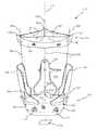
- FIG. 1is a perspective view of a two piece heart valve assembly including a gasket member having a plurality of guide shields extending therefrom and a valve member.
- FIG. 2is a perspective view of a gasket member including an annular prosthesis and a plurality of guide shields and guide rails extending from an annular prosthesis, which may included in the assembly of FIG. 1 .
- FIG. 3is a front view of an exemplary embodiment of a guide shield that includes suture holes, a receiving slot for a guide rail, and a belt and buckle.
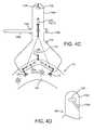
- FIGS. 4A and 4Bare top and side views, respectively, of a guide shield being attached to a gasket member with sutures.
- FIG. 4Cis a detail of an alternative method for releasably securing the guide shield of FIGS. 4A and 4B to anchor loops on a gasket member.
- FIG. 4Dis a detail of an alternative embodiment of an upper end of a guide shield.
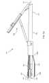
- FIGS. 5A-5Care side, perspective, and end views, respectively, of a tool for delivering the gasket member of FIG. 2 .
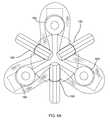
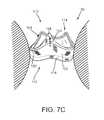
- FIGS. 6A and 6Bare end and side views, respectively, of a distal end of the tool of FIGS. 5A-5C , showing the gasket of FIG. 2 (with the guide shields and guide rails omitted for clarity) secured thereto in a folded or contracted condition.
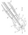
- FIGS. 7A-7Care cross-sectional views of a biological annulus, showing a method for implanting a heart valve assembly including the gasket of FIG. 2 .
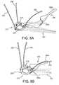
- FIGS. 8A and 8Bare perspective views of a gasket member including a guide shield slidable towards and away from the gasket member.
- FIGS. 9A and 9Bare perspective views of a gasket member including a guide shield constrained within a removable sleeve.
- FIGS. 1 and 2shows an embodiment of a heart valve assembly 110 that generally includes a gasket member 112 and a valve member 114 .
- the gasket member 112is an annular shaped body generally defining a plane 116 and a central longitudinal axis 117 extending substantially perpendicular to the plane 116 .
- the gasket member 112includes an annular ring 118 , a sewing cuff 120 , a plurality of elongate guide rails, leaders, or other elements 150 extending from the sewing cuff 120 or other portion of the gasket member 112 , and a plurality of guide shields 156 removably attached to the gasket member 112 .
- a fabric covering 121may be provided on one or more components of the gasket member 112 , e.g., over the annular ring 118 and/or over a core of the sewing cuff 120 , as described further below.
- the annular ring 118may have a generally circular shape.
- the annular ring 118may have a multi-lobular shape about the circumference, e.g., including three lobes separated by scallops or cusps (not shown).
- the annular ring 118may be formed from an elastic or superelastic material, for example, metal, such as Nitinol, stainless steel, and the like, a polymer, or a composite material. Such material may facilitate compression and/or expansion of the annular ring 118 , as described further below.
- the annular ring 118may be cut from a flat sheet of base material having a desired thickness for the annular ring 118 , for example, by laser cutting, mechanical cutting, and the like.
- the annular ring 118may be initially formed as a long band of material, having a width corresponding to the desired width of the annular ring 118 and a length corresponding to the desired circumference of the annular ring 118 .
- the bandmay be wrapped around a mandrel or otherwise restrained in a generally cylindrical shape with the ends adjacent to one another, and the band may be heat treated or otherwise processed to program the generally cylindrical shape into the material to create the annular ring 118 .
- the generally cylindrical shapemay include the ends overlapping one another, spaced apart from one another to provide an open “C” shape, or attached to one another.
- the annular ring 18may be manufactured from a solid rod of material, e.g. Nitinol, stainless steel, a polymer, or composite material, e.g., by machining, electrical discharge machining (“EDM”), laser cutting, or other processes.
- the annular ring 118may be heat treated to program a shape memory into the band material, e.g., when the material is in an austenitic state.
- the programmed shapemay be an enlarged or relaxed condition, e.g., having a substantially circular shape.
- the composition of the materialmay be such that the annular ring 118 transforms to a substantially martensitic state substantially below body temperature, e.g., at or below ambient temperatures (e.g., 20° C. or less).
- the annular ring 118may be relatively soft such that the annular ring 118 may be plastically compressed or otherwise deformed, e.g., into a contracted condition to facilitate delivery, as described below.
- a transition temperature of the materialmay be set such that the annular ring 118 transforms substantially back to an austenitic state close to or at about body temperature (e.g., 37° C. or more).
- body temperaturee.g. 37° C. or more.
- the materialmay be programmed to assume an austenitic state at both ambient and body temperatures, but within the elastic or superelastic range of the material.
- the annular ring 118may be elastically compressed into the contracted condition, but may resiliently expand towards the enlarged condition when released from any constraints maintaining the annular ring 118 in the contracted condition.
- the annular ring 118may be at least partially covered with fabric, e.g., for tissue ingrowth, by wrapping fabric around the annular ring 118 , while accommodating expansion and contraction of the annular ring 118 .
- fabrice.g., for tissue ingrowth
- sutures and the likemay be used to secure the fabric to the annular ring 118 , e.g., at locations removed from the ends, such as at an intermediate location about the circumference of the annular ring 118 .
- the entire annular ring 118may be free to slide within the fabric wrapped around the annular ring 118 .
- the gasket member 112may also include a flexible skirt and/or baleen elements (not shown), e.g., surrounding the annular ring 118 and/or within the fabric covering the annular ring 118 , which may bias a portion of the fabric covering outwardly.
- a flexible skirt and/or baleen elementsnot shown, e.g., surrounding the annular ring 118 and/or within the fabric covering the annular ring 118 , which may bias a portion of the fabric covering outwardly.
- the sewing cuff 120may be attached to or otherwise extend around the annular ring 118 .
- the sewing cuff 120may simply be one or more layers of fabric or other material covering at least a portion of the annular ring 118 .
- a layer of fabricmay cover all of the annular ring 118 (other than any connectors and/or bearing surfaces, if any) and/or may include a section of material extending radially outwardly from the annular ring 118 .
- the sewing cuff 120may include flexible core material (not shown) that may be attached to or otherwise extend around the annular ring 118 .
- the coremay be secured around the annular ring 118 by an interference fit, bonding, fusing a portion of the core, and the like.
- the coremay be substantially covered with fabric, similar to the annular ring 118 .
- the coremay include a lattice (not shown) extending around a circumference of the core, e.g., including at least two spaced apart circumferential elements and a plurality of ribs or transverse elements extending between the circumferential elements, thereby defining openings through the lattice.
- the openingsmay be completely open, i.e., free from any material.
- the openingsmay be recesses including a relatively thin wall of core material, i.e., that is substantially thinner than the circumferential elements and/or ribs.
- the coremay include a base or web and a plurality of fins or ribs extending from the web to provide a flexible structure that may facilitate sealing between the sewing cuff 120 and valve member 114 .
- Exemplary materials for the coreinclude silicone or other elastomeric materials, foam, fabric, felt, polymers, and the like.
- the coremay include swellable material, e.g., foam or sponge materials that may expand when exposed to fluid, such as blood.
- the materialsmay be molded or otherwise formed into the core, e.g., using known molding, extrusion, cutting, or other manufacturing procedures.
- the coremay be injection molded or otherwise formed in its annular shape.
- the coremay be molded or otherwise formed as a flat sheet, and rolled into the annular shape.
- the ends of the sheetmay be attached to one another, e.g., using sutures, adhesives, ultrasonic welding, and the like.
- one or more wedgesmay be cut out of the band to provide a desired tapered but annular shape.
- portions of the coremay be disconnected from other portions, e.g., to prevent puckering. For example, if the core is formed from a rolled sheet (not shown), ends of the sheet (also not shown) may remain loose to allow the ends to move relative to one another.
- the sewing cuff 120may adopt an undulating annular shape or a generally planar annular shape.
- the sewing cuff 120may also be tapered, as shown in FIG. 1 , e.g., having a larger diameter or circumference about an upper edge than about an edge adjacent the annular ring 118 .
- the tapered shape of the sewing cuff 120may define an angle relative to the longitudinal axis 117 , e.g., between about twenty and forty five degrees (20-45°).
- the material of the coremay be substantially flexible, e.g., manufactured in a desired annular shape, yet easily deformed, e.g., deflected, stretched, and/or compressed.
- the coremay be sufficiently flexible to be “floppy,” i.e., such that the core conforms easily to the particular anatomy and/or implantation arrangements encountered during implantation.
- the coremay conform to the surrounding anatomy and/or may deform when the valve member 114 is secured to the gasket member 112 , e.g., to enhance sealing between the valve member 114 and the gasket member 112 , as described further below.
- the gasket member 112may include one or more additional components.
- the gasket member 112may include a collar or stand-off (not shown) that extends upwardly from the sewing cuff 120 for receiving the valve member 114 . Additional information on materials, construction, and/or components of the gasket member 112 may be found in U.S. Publication Nos. US 2004/0122516, filed as Ser. No. 10/327,821, US 2005/0165479, filed as Ser. No. 10/765,725, US 2006/0195184, filed as Ser. No. 11/069,081, and US 2007/0016285, filed as Ser. No. 11/420,720, and in co-pending application Ser. No. 11/567,735, filed Dec. 6, 2006. The entire disclosures of these references are expressly incorporated by reference herein.
- the guide rails 150may include elongate bands, fibers, or filaments including a first or distal end 153 attached or otherwise secured to the gasket member 112 and a second or proximal end 152 .
- the guide rails 150may include one or more depth markers or other elements (not shown) spaced apart along at least a portion of their lengths, e.g., immediately adjacent the first end 153 and/or at one or more predetermined distances from the gasket member 112 .
- the guide rails 150may include one or more retention elements 154 , e.g., locking beads, latches, catches, ratcheting elements, and the like, for securing the valve member 114 to or adjacent the gasket member 112 .
- retention elements 154e.g., locking beads, latches, catches, ratcheting elements, and the like, for securing the valve member 114 to or adjacent the gasket member 112 .
- the guide rails 150may be flat bands, e.g., formed from plastic or other material, and may have the retention elements 154 formed therein or attached thereto, as described in application Ser. No. 11/567,735, incorporated by reference herein.
- the guide rails 150may be formed from wire or suture materials, e.g., formed from plastic, such as polyethylene, metal, such as stainless steel, cat gut, or composite materials, using known methods.
- the guide rails 150may have sufficient column strength to maintain a substantially straight and/or upward orientation, but may be sufficiently flexible to be movable, e.g., laterally towards or away from the central axis 117 of the gasket member 112 .
- the retention elements 154may be integrally formed on the guide rails 150 , e.g., at the time the guide rails 150 are formed or by removing some of the guide rail material, and/or may be separate elements (made from the same or different materials than the guide rails 150 ) that are bonded, fused, or otherwise attached to the guide rails 150 at predetermined locations.
- the retention elements 154 on the guide rails 150may include knots (not shown) tied onto the guide rails 150 and/or beads (also not shown) formed on the guide rails 150 at predetermined locations.
- only one retention element 154is shown on each guide rail 150 , multiple retention elements 154 may be provided spaced apart from one another along each guide rail 150 , similar to the elements shown in US 2005/0165479, incorporated by reference herein.
- the retention elements 154may include tapered or ramped proximal edges 154 a and substantially blunt distal edges 154 b .
- the tapered proximal edges 154 amay provide a transition allowing the valve member 114 to be passed distally over the retention elements 154 .
- the blunt distal edges 154 bmay provide locks that prevent the valve member 114 from being passed proximally back over the retention elements 154 , as described further below.
- each guide rail 150may be attached to the gasket member 112 , e.g., using one or more sutures, adhesives, and the like.
- each guide rail 150may include one or more holes (not shown) through the distal end 153 that may receive one or more sutures. The sutures may be directed through the holes and driven through the fabric covering and/or a portion of the sewing cuff 120 to secure the distal end 153 to the gasket member 112 .
- the distal endsmay be attached to the gasket member 112 using an adhesive, by receiving the distal end 153 through a portion of the gasket member 112 , e.g., through the fabric covering or sewing cuff 120 , and the like.
- the distal end 153may be fused to or embedded in a core of the sewing cuff 120 .
- the guide rails 150may be spaced apart from one another about the circumference or periphery of the gasket member 112 .
- the guide rails 150may be provided on portions of the gasket member 112 that are aligned with the commissures (not shown) on the valve member 114 and/or a biological annulus into which the gasket member 112 is to be implanted.
- three guide rails 50may be provided, as shown in FIGS. 1 and 2 .
- one, two, or more guide railsmay be provided on the gasket member 112 .
- the guide shields 156may extend upwardly and/or outwardly from the sewing cuff 120 , e.g., to at least partially define a passage 124 therebetween for guiding the valve member 114 downwardly towards the gasket member 112 , as shown in FIG. 1 and described further below.
- the guide shields 156may be formed from a relatively thin and/or transparent sheet, e.g., a plastic such as polyester, Mylar®, or any other polymeric film or material, such as high-density or low-density polyethylene, polystyrene, and the like.
- the sheetmay be cut or otherwise formed to into a desired shape, such as a “mandolin” or inverted “Y” shape, e.g., defining a relatively wide base 156 a that may be attached to the gasket member 112 and a relatively narrow loose upper end 156 b .
- the guide shieldsmay have a generally triangular (not shown), e.g., optionally including a central open portion, thereby defining a pair of inverted “V” shaped bands (not shown) extending from the upper end 156 b to the base 156 a.
- the guide shields 156may be sufficiently rigid to maintain their shape and/or orientation, but may be sufficiently flexible to be deflected, folded, or bent, if desired, e.g., to facilitate access around the guide shields 156 .
- the transparency of the filmmay be pretty useful for seeing through the guide shields 156 , e.g., to locate the gasket member 112 relative to or within a biological annulus, relative to other anatomical structures, and the like, without having to move the guide shields 156 out of the way.
- the upper end 156 bmay include one or more openings 158 for receiving the guide rails 150 therethrough.
- the openings 158may partially restrain the guide rails 150 away from the passage 124 or otherwise out of the operator's field of view during a procedure when the guide rails 150 are received in the openings 158 , as described further below.
- the upper ends 156 b of the guide shields 156may be split, e.g., including a slot 158 a extending down to the openings 158 to facilitate inserting and/or removing the guide rails into/from the openings 158 .
- the upper end 156 b ′ of the guide shields 156 ′may include a slot 158 a ′ that extends to or enters the opening 158 ′ from the side or below and extends to a side edge of the upper ends 156 b ′.
- a slot 158 a ′may provide side access to the opening 158 ′, yet still provide an opening 158 ′ that may securely capture a guide rail 150 (not shown in FIG. 4D ).
- the guide shields 156 and/or guide rails 150may include one or more other detents, connectors, and the like for releasably constraining the guide rails 150 relative to the guide shields 150 .
- the upper end 156 b of the guide shield 156may include a seatbelt or “zip tie” arrangement 159 for releasably constraining a guide rail adjacent the guide shield 156 .
- the arrangement 159may include an elongate belt or tab 159 a extending laterally from the upper end 156 b of the guide shield 156 , and a slot or other receptacle 159 b opposite the tab 159 a .
- the tab 159 amay include one or more connectors 159 c , e.g., ratchets, detents, or other retention elements, that may secure the tab 159 a at one or more positions within the receptacle 159 b .
- the arrangement 159may facilitate imparting a desired shape to the guide shield 156 , e.g., by constraining the guide shield 156 in a curved shape around the longitudinal axis 117 when the tab 159 a is securely received in the receptacle 159 b , e.g., to provide better access and/or visualization to the gasket member 112 during implantation.
- each guide shield 156may include a plurality of holes for facilitating removably attaching the guide shield 156 to the gasket member 112 .
- a plurality of holes 155 amay be disposed along the base 156 a of each guide shield 156 for receiving sutures or other fastening elements, which may be driven into the fabric covering 121 , sewing cuff 120 , and/or other portion of the gasket member 112 , as best seen in FIG. 4A .
- the guide shield 156may include a plurality of holes 155 b , 155 c extending and/or spaced apart generally axially along the guide shield 156 , e.g., a vertical array of holes 155 b along the base 156 a and a set of holes 155 c along the upper end 156 b.
- the vertical array of holes 155 b along the base of 156 amay provide preferential flexibility along an axis defined by the holes 155 b , e.g., to act as a hinge or to provide a preferred bending edge for shaping the guide shield 156 , for example, during folding process.
- the guide shields 156may be bent vertically, e.g., along the axis of the holes 155 b , to shape the guide shields 156 similar to the commissures of the sewing cuff 120 .
- the bendsmay reduce the force required to deform the guide shields 156 during bending and/or to provide a more compact folded shape when the gasket member 112 is loaded onto a gasket delivery tool, such as that described elsewhere herein.
- the bendmay bias the guide shield 156 towards a desired shape, e.g., when the gasket member 112 has been released or otherwise placed within a biological annulus or other implantation site.
- FIGS. 4A and 4Ban exemplary method is shown for attaching a guide shield 156 to a gasket member 112 .
- a suture 157 including a first end 157 a and a second end 157 bmay be routed through the holes 155 to removably secure the guide shield 156 relative to the gasket member 112 .
- the first end 157 amay be routed through one or more holes 155 c in the upper end 156 b , through one or more holes in the intermediate array of holes 155 b , and into a hole 155 a on one end of the base 156 a .
- the suture 157 amay then be directed through the holes 155 a along the base 156 a and through the fabric covering 121 of the gasket member 112 , e.g., from the one end of the base 156 a to the opposite end thereof.
- the suture 157may then be routed back through one or more of the array of holes 155 b and the set of holes 155 c , and then the first end 157 a may be tied or otherwise secured to the second end 157 b , e.g., by knot 157 c.
- the sewing cuff 120 of the gasket member 112may include one or more anchoring loops 123 , e.g., sewn into or otherwise secured to the sewing cuff 120 , fabric covering 121 , or otherwise to the gasket member 112 .
- the loops 123may facilitate passing sutures therethrough, e.g., when releasing the guide shields 156 from the gasket member 112 .
- the loops 123are shown at locations corresponding to holes 155 a adjacent the opposite ends or wings of the base 156 a.
- An exemplary method for attaching the guide shield 156 to the gasket member 112may include initially providing a set of guide shields 156 , e.g., three, made using the procedures and/or materials described elsewhere herein. Before sewing the guide shields 156 to the gasket member 112 , the guide shields 156 may be cleaned and/or sterilized, e.g., by ultrasonic cleaning and/or rinsing with purified water. The guide shields 156 may be folded vertically, e.g., along the vertical holes 155 b and/or to bend the upper end 156 b outwardly.
- the guide shields 156may then be sutured to the gasket member 112 , e.g., by initially putting a suture anchor loop on the surface of the gasket member 112 , e.g., using a needle pair on ends of a length of suture, e.g., at the center of the base 156 a .
- the suturesmay then be stitched outwardly towards the ends of the base 156 a , e.g., through the anchor loops 123 , and then up to the upper holes 155 c , where the suture ends may be tied, as shown in FIG. 4C .
- the guide shield 156may be removed from the gasket member 112 simply by cutting or otherwise severing the suture 157 .
- a chain stitch or other stitchmay be used, e.g., that may be loosened upon being cut at a single location, which may facilitate removing the sutures and, consequently, the guide shields 156 after implantation.
- one of the ends 157 a , 157 b of the suture 157may be looped and/or secured through the holes 155 c in the upper end 156 b , e.g., to prevent the suture 157 from separating entirely from the shield guard 156 .
- one side of the suture 157may be cut below the location where the end(s) 157 a , 157 are secured, and the suture may then be pulled from the other side, e.g., to cause the cut side to travel through the various holes 155 .
- the suture 157may be separated entirely from the gasket member 112 , thereby allowing the guide shield 156 to be removed from the gasket member 112 .
- the suture 157may be removed with the guide shield 156 , thereby avoiding the risk of leaving the suture 157 or a portion thereof behind.
- this configurationmay allow the suture 157 to be cut and the guide shield 156 removed simply by introducing a cutting tool (not shown) to the upper end 156 b of the guide shield 156 , rather than requiring the cutting tool to be introduced all the way to the base 156 a of the guide shield 156 .
- the suture 157may be formed from slippery material, e.g., Gore-Tex® expanded polytetrafluoroethylene (ePTFE), polyester, ultra-high molecular weight polyethylene (UHMWPE), polyethylene, and the like, which may slide easily out of the various holes 155 when pulled from one end.
- slippery materiale.g., Gore-Tex® expanded polytetrafluoroethylene (ePTFE), polyester, ultra-high molecular weight polyethylene (UHMWPE), polyethylene, and the like, which may slide easily out of the various holes 155 when pulled from one end.
- ePTFEGore-Tex® expanded polytetrafluoroethylene
- UHMWPEultra-high molecular weight polyethylene
- polyethylenepolyethylene
- one or more sutures 157may be secured through the holes 155 a in the base 156 a and the fabric covering 121 (or other component of the gasket member 112 ).
- individual suturescould be introduced through respective holes and portions of the gasket member 112 .
- the holes 155may be deleted and the suture 157 may simply be directed through desired locations of the guide shield 156 , e.g., using a sharp needle or other instrument carrying the suture 157 .
- the valve member 114generally includes an annular shaped body or frame 132 and one or more leaflets or other valve elements 133 .
- the valve member 114may include a fabric covering 135 , similar to the gasket member 112 , e.g., covering the frame 132 and/or other components of the valve member 114 , other than the leaflets 133 .
- the frame 132may have a noncircular, e.g., a multiple lobular shape corresponding to a shape of the biological annulus within which the valve member 114 is to be implanted.
- the valve member 114may have a tri-lobular shape, including three lobes separated by cusps or scallops 134 , e.g., corresponding to a sinus of Valsalva above an aortic valve site.
- the valve member 114may be a bioprosthetic valve member, e.g., an annular frame 132 carrying a plurality of tissue leaflets 133 .
- the frame 132may include a plurality of struts (also not shown for clarity) that may be attached to and/or otherwise carry the leaflets 133 .
- the strutsmay include a laminate structure, including two or more sheets of flexible material, similar to the valves disclosed in U.S. Pat. No. 6,371,983, and U.S. Publication No. US 2006/0276888, filed as Ser. No. 11/144,254, the entire disclosures of which are expressly incorporated by reference herein.
- valve member 114may be a connecting device to which a valve (not shown) may be connected or that may otherwise receive a valve component, such as the connection adapter elements shown in U.S. Publication No. US 2005/0043760, filed as 10/646,639, the entire disclosure of which is expressly incorporated by reference herein.
- valve 114may include a mechanical valve or other valve (not shown), such as those disclosed in US 2005/0165479 and US 2007/0016285, incorporated by reference herein.
- the valve member 114may include one or more introducers or receivers (not shown) through which the guide rails 150 may be received.
- the receiversmay include receptacles attached to desired locations on the valve member 114 , e.g., to the fabric covering 135 at the commissures or other desired locations around the periphery of the frame 132 .
- the receptaclesmay include one or more connectors (not shown) that interact with connectors on the guide rails 150 , such as retention elements 154 .
- the valve member 114may simply include slots, e.g., through the fabric covering 135 and/or frame 132 , through which the guide rails 150 may be slidably received.
- valve member 114 and/or gasket member 112may include one or more connectors (not shown) for securing the valve member 114 to or adjacent to the gasket member 112 .
- the gasket member 112may include a collar (not shown) extending upwardly from the sewing cuff 120 and/or annular ring 118 , and the valve member 114 may be received in the collar. Additional information on apparatus and methods for securing the valve member 114 relative to the gasket member 112 may be found in the references incorporated by reference above or in U.S. Publication No. US 2006/0235508, filed as 11/279,246, or U.S. application Ser. No. 11/668,459, filed Jan. 29, 2007, the entire disclosures of which are expressly incorporated by reference herein.
- a gasket delivery tool 160that generally includes a shaft 162 including a proximal end 161 , a distal end 163 , and an actuator 165 on the proximal end 161 .
- the delivery tool 160may include a plurality of supports 166 on the distal end, e.g., spaced apart around a longitudinal axis 167 of the tool 160 .
- the supports 166may be substantially rigid cylindrical hubs for receiving a gasket member 112 (such as any of those described herein) around the supports 166 .
- the supports 166may generally define a diameter that is smaller than the gasket member 112 , e.g., smaller than the radius of the annular ring 118 .
- the tool 160may include a plurality of arms 168 movably mounted to the distal end 163 .
- one end of the arms 168may be fixedly attached to the distal end 163 of the tool 160 , e.g., proximal to the supports 166 , and the other end may include tips disposed adjacent the supports 166 .
- the arms 168may be offset radially relative to the supports 166 such that each arm 168 is disposed between adjacent supports 166 .
- the arms 168may be movable from an outer position (not shown), defining a radius larger than the gasket member 112 to an inner position (shown in FIGS. 6A and 6B ), wherein the tips are disposed between and/or within the supports 166 .
- the actuator 165may include a lever or other mechanism that may selectively move the tips of the arms 168 between the outer and inner positions.
- a gasket member 112may be placed between the supports 166 and the arms 168 , e.g., with the nadir regions of the sewing cuff 120 aligned radially with the arms 168 .
- the arms 168may then be directed to the inner position, thereby securing the gasket member 112 between the supports 166 and the arms 168 . As shown in FIGS.
- the gasket member 112may be deformed from a generally circular expanded condition to a multiple lobed, e.g., “shamrock” shaped contracted condition defining lobes.
- the gasket member 112may be elastically deformed into the contracted condition or plastically deformed, e.g., in a martensitic state, similar to the previous embodiments.
- the heart valve assembly 110may be implanted within a patient's body, e.g., within or adjacent to a biological annulus 90 .
- the biological annulus 90may be the site for replacing an existing natural or previously implanted heart valve, such as a tricuspid, mitral, aortic, or pulmonary valve within a patient's heart (not shown).
- the patientBefore implanting the heart valve assembly 110 , the patient may be prepared for the procedure using known methods. For example, the patient may be placed on cardiopulmonary bypass (CPB), and the patient's heart may be exposed, e.g., by sternotomy, thoracotomy, or other open or minimally invasive procedure. An incision may be created in the blood vessel above the valve being replaced (not shown), e.g., the aorta for an aortic valve replacement, in order to access the annulus 90 . The existing natural or prosthetic heart valve and/or leaflets (also not shown) may then be removed from the annulus 90 using known methods.
- CPBcardiopulmonary bypass
- a heart valve assembly 110including a gasket member 112 and a valve member 114 may be selected based upon the anatomy encountered, e.g., having a plurality of lobes, matching the lobes of the biological annulus 90 and/or having a cross-sectional dimension corresponding to the interior cross-section of the biological annulus 90 .
- a gasket member 112 and/or valve member 114may be selected having a size that is larger than the biological annulus 90 .
- the gasket member 112may have a diameter in its relaxed condition that is slightly larger than the biological annulus 90 , e.g., such that the gasket member 112 may at least partially dilate the biological annulus 90 upon implantation.
- the valve member 114may have a diameter or other cross-section that is substantially larger than the biological annulus 90 , e.g., for supra-annular or intra-sinus implantation, which may accommodate the larger size.
- the gasket member 112may be loaded onto the tool 160 , e.g., in the contracted condition as described above.
- the gasket member 112may be loaded onto the tool 160 immediately before introduction, or may be prepared in advance, as desired.
- the gasket member 112 and distal end 163 of the tool 160may then be directed into the biological annulus 90 in the direction of arrow 94 .
- the tool 160may be rotated about its longitudinal axis, if necessary, to align the lobes of the gasket member 112 with the commissures (not shown) of the biological annulus 90 .
- the gasket member 112may be positioned such that the annular ring 118 is received within the valve annulus, e.g., from which the native leaflets (or prosthesis) has been removed, and the sewing cuff 120 is disposed supra-annularly, e.g., within the Sinus of Valsalva.
- the arms 168may then be directed to the outer position, e.g., using the actuator 165 on the tool 160 , thereby releasing the gasket member 112 within the biological annulus, as shown in FIG. 7B .
- the gasket member 112may resiliently expand towards its original expanded condition when released, e.g., to dilate the biological annulus 90 or otherwise direct the surrounding tissue 98 outwardly.
- the tool 160may be removed, leaving the gasket member 112 in place within the biological annulus 90 .
- the annular ring of the gasket member 112may be located within a native valve annulus, while the sewing cuff 120 is located in a supra-annular position relative to the native valve annulus.
- a dilation tool(not shown) may be advanced into the gasket member 112 and expanded to forcibly (e.g., plastically) expand the annular ring 118 within the biological annulus 90 .
- the guide shields 156 and guide rails 150may extend upwardly and/or outwardly from the gasket member 112 .
- the guide shields 156may be sufficiently long such that upper ends of the guide shields 156 are disposed outside the patient's body and/or outside the biological annulus.
- the guide shields 156may extend through an incision or other relatively narrow passage above the biological annulus 90 .
- the guide shields 156may at least partially define a passage 124 communicating through the biological annulus 90 , the inner surfaces of the guide shields 156 providing a smooth and/or lubricious surface to facilitate advancing the valve member 114 into the tissues annulus 90 towards the gasket member 112 .
- the gasket member 112may be secured to the surrounding tissue 98 .
- a tool(not shown) may be used to deliver a plurality of fasteners 96 through the sewing cuff 120 and into the surrounding tissue 98 . Forceps, tweezers, or other tools may be used, if desired, to manipulate components of the gasket member 112 during delivery of the fasteners 96 .
- the tool(not shown) may be used to hold the sewing cuff 120 and/or to move the guide rails 150 and/or guide shields 156 out of the way.
- the guide shields 156may not obscure observation and/or access into the biological annulus to deliver the fasteners 96 .
- Exemplary fasteners and methods for using them to secure the gasket member 112may be found in U.S. Publication Nos. US 2004/0122516, filed as Ser. No. 10/327,821, US 2005/0043760, filed as Ser. No. 10/646,639, US 2005/0080454, filed as Ser. No. 10/681,700, and US 2006/0122634, filed as Ser. No. 11/004,445, the entire disclosures of which are incorporated by reference herein.
- the desired valve member 114may be preloaded onto a valve holder tool (not shown) by the manufacturer or the user, or a desired size valve (if multiple sizes are available) may be selected and loaded onto the valve holder, e.g., using one or more sutures.
- a valve sizeror a series of progressively larger valve sizers may be directed into the biological annulus 90 to determine the appropriate size prosthetic valve to be delivered into the biological annulus 90 .
- guide rails 150 and guide shields 156may extend out of the biological annulus 90 and/or otherwise from the gasket member 112 .
- Each guide rail 150may be loaded through a receiver 130 on the valve member 114 , such as those described elsewhere herein, until the guide rail 150 exits an upper end of the receiver 130 .
- the guide rails 150may be inserted into receptacles (not shown) in the valve holder, e.g., before or after being loaded through the receivers 130 on the valve member 114 .
- the valve holder, carrying the valve member 114may then be directed into the biological annulus 90 , e.g., over the guide rails 150 .
- the guide rails 150are coupled to and/or constrained by the guide shields 156 , the guide rails may be released from the guide shields 156 to allow the valve member 114 to slide freely down the guide rails 150 towards the gasket member 112 .
- the valve member 114may slidably contact inner surfaces of the guide shields 156 extending from the gasket member 112 .
- the guide shields 156may provide a substantially smooth and/or lubricious surface, which may facilitate advancing the valve member 114 through a narrow and/or partially obstructed passage into the biological annulus 90 .
- at least the inner surfaces of the guide shields 156may be coated with a lubricious coating and the like to minimize friction between the guide shields 156 and the valve member 114 .
- the guide rails 150may include one or more markers 151 at predetermined locations, e.g., known distances from the gasket member 112 .
- the markers 151may provide the user confirmation of the location of the valve member 114 relative to the gasket member 112 , and/or may provide visual confirmation when the valve member 114 has been secured to the gasket member 112 , e.g., by indicating that the valve member 114 has passed over retention elements 154 on the guide rails 150 , has been received in a collar (not shown) on the gasket member 112 , and/or otherwise has been connected to the gasket member 112 .
- valve member 114may be advanced to engage the connectors on the valve member 112 with retention elements 154 and the like on the gasket member 112 .
- the usermay pull or otherwise subject the guide rails 150 to proximal tension, while advancing the valve holder and/or valve member 114 , e.g., until a “click” or other audible and/or tactile feedback is provided that confirms that the cooperating connectors are engaged.
- Each set of connectorsmay be engaged sequentially or simultaneously.
- the guide rails 150may include a weakened region, e.g., above the retention elements 154 or may be otherwise severable above the retention elements 154 .
- the guide rails 150may then be severed or otherwise separated from the gasket member 112 , e.g., above the retention elements 154 , and the guide rails 150 removed from the patient's body.
- an actuator (not shown) of the valve holder(also not shown) may be pulled proximally or otherwise manipulated to break or otherwise sever the guide rails 150 at their respective weakened regions.
- the guide shields 156may be removed from the gasket member 112 before or after severing the guide rails 150 .
- the sutures 157may be cut or otherwise severed to release the guide shields 156 and allow their separation from the gasket member 112 .
- the sutures 157may simply unravel, allowing the guide shields 156 and sutures 157 to be removed simultaneously from the gasket member 112 .
- the guide shields 156 and sutures 157may be removed separately from the gasket member 112 and from the patient's body.
- the valve member 114may be released from the valve holder, e.g., before or after severing the guide rails 150 and/or removing the guide shields 156 , thereby providing the heart valve assembly 110 implanted within the biological annulus 90 .
- FIGS. 8A and 8Banother embodiment of a gasket member 212 is shown that includes a set of guide shields 256 (one shown for simplicity).
- the gasket member 212may be formed similar to other embodiments described herein, e.g., including an annular ring 218 , sewing cuff 220 , and a plurality of guide rails or other leaders 250 .
- Each of the gasket shields 256may be formed generally similar to other embodiments described herein, e.g., including a broad base 256 a and upper end 256 b , which may include one or more features (not shown) for releasably constraining the guide rails 250 to respective guide shields 256 .
- each gasket shield 256may include one or more sutures or other filaments 257 secured to the base 256 a , which may be slidably received through a portion of the gasket member 212 , e.g., through the sewing cuff 220 and/or fabric covering.
- the sutures 257may be received through loops (not shown) formed in the sewing cuff 220 , if desired.
- the suture(s) 257may be sufficiently long to extend completely out of a patient's body when the gasket member 212 is introduced into a biological annulus (not shown).
- the free ends of the sutures 257may be braided or otherwise connected to one another such that the sutures 257 are pulled together.
- the guide shields 256may be provided away from the gasket member 212 , but with the sutures 257 slidably received through the gasket member 212 .
- the gasket member 212may then be introduced into a biological annulus and implanted or otherwise secured therein, similar to other embodiments described elsewhere herein.
- the sutures 257may be sufficiently long that the guide shields 256 may be disposed outside the patient's body, e.g., maintained out of the operating field.
- the gasket member 212may be more easily manipulated and/or monitored during introduction and implantation. For example, one or more clips, sutures, or other fasteners (not shown) may be delivered through the sewing cuff 220 into surrounding tissue without having to manipulate the guide shields out of the way.
- the guide shields 256may then be directed into biological annulus, e.g., by pulling the ends of the sutures 257 . This action may cause the sutures 257 to slide through the gasket member 212 , pulling the guide shields 256 into the biological annulus and against the sewing cuff 220 , as shown, or otherwise adjacent the gasket member 212 .
- a valve(not shown) may then be introduced into the biological annulus and secured to the gasket member 212 , similar to other embodiments described elsewhere herein.
- the upper ends 256 b of the guide shieldsmay simply be pulled, thereby causing the sutures 257 to slide through and out of the gasket member 212 .
- the guide shields 256may be provided adjacent the gasket member 212 , as shown in FIG. 8B , before the gasket member 212 is introduced into the biological annulus.
- the gasket member 212may be carried on a delivery tool (not shown), e.g., in a contracted condition, which may constrain the guide shields 256 with the gasket member 212 . This may facilitate introduction of the gasket member 212 without dealing with the guide shields 256 being loose or otherwise separate from the gasket member 212 , which may also require manipulating the sutures 257 to keep them out of the way.
- the guide shields 256may be pulled out of the biological annulus, i.e., to the position shown in FIG. 8A , before delivering fasteners through the gasket member 212 , if desired. After delivering the fasteners, the guide shields 256 may be pulled into the biological annulus, as described above.
- the guide shields 256may remain adjacent the gasket member 212 while fasteners are delivered, similar to the previous embodiments. After introducing and/or securing a valve to the gasket member 212 , the guide shields 256 may be removed, similar to the previous embodiments.
- a gasket member 312 and guide shields 356may be provided, similar to other embodiments described elsewhere herein, e.g., including an annular ring 318 and sewing cuff 320 .
- the guide railsmay be constrained in a rolled or other contracted configuration.
- a tubular sleeve 340may be received around at least a portion of the guide rails 356 after rolling, folding, or otherwise reducing the width of the guide rails 356 .
- the sleeve 340may be substantially flexible and/or transparent, e.g., formed from material similar to the guide shields 356 , and may have a length longer or shorter than the guide shields 356 .
- the sleeve 340may minimize obstruction caused by the guide shields 356 during introduction, e.g., maximizing access around the gasket member 212 , e.g., to deliver fasteners therethrough, and the like.
- the sleeve 340may simply be slid axially from around the guide shields 356 , e.g., by pulling an outer end of the sleeves 340 out of the biological annulus.
- the guide shields 356may then unroll, unfold, or otherwise open to provide surfaces for guiding and/or facilitating introduction of a valve into the biological annulus towards the gasket member 312 .
- the sleeves 340may include one or more weakened regions (not shown), e.g., extending axially along the sleeves 340 , that may be torn or otherwise separated to facilitate removing the sleeves 340 from around the guide shields 356 .
- the proceduremay be completed using any of the methods described herein.
- the guide shields 356may be removed by severing one or more sutures securing the guide shields 356 to the gasket member 312 .
- the guide shields 356may be slidable from the gasket member 312 , e.g., as described above with reference to FIGS. 8A and 8B .
Landscapes
- Health & Medical Sciences (AREA)
- Cardiology (AREA)
- Engineering & Computer Science (AREA)
- Biomedical Technology (AREA)
- Heart & Thoracic Surgery (AREA)
- Transplantation (AREA)
- Oral & Maxillofacial Surgery (AREA)
- Vascular Medicine (AREA)
- Life Sciences & Earth Sciences (AREA)
- Animal Behavior & Ethology (AREA)
- General Health & Medical Sciences (AREA)
- Public Health (AREA)
- Veterinary Medicine (AREA)
- Mechanical Engineering (AREA)
- Prostheses (AREA)
Abstract
Description
Claims (38)
Priority Applications (1)
| Application Number | Priority Date | Filing Date | Title |
|---|---|---|---|
| US11/742,390US9295548B2 (en) | 2006-04-29 | 2007-04-30 | Guide shields for multiple component prosthetic heart valve assemblies and apparatus and methods for using them |
Applications Claiming Priority (3)
| Application Number | Priority Date | Filing Date | Title |
|---|---|---|---|
| US74603806P | 2006-04-29 | 2006-04-29 | |
| US91474207P | 2007-04-29 | 2007-04-29 | |
| US11/742,390US9295548B2 (en) | 2006-04-29 | 2007-04-30 | Guide shields for multiple component prosthetic heart valve assemblies and apparatus and methods for using them |
Related Parent Applications (1)
| Application Number | Title | Priority Date | Filing Date |
|---|---|---|---|
| US74603806PContinuation | 2006-04-29 | 2006-04-29 |
Publications (2)
| Publication Number | Publication Date |
|---|---|
| US20070260305A1 US20070260305A1 (en) | 2007-11-08 |
| US9295548B2true US9295548B2 (en) | 2016-03-29 |
Family
ID=38266267
Family Applications (2)
| Application Number | Title | Priority Date | Filing Date |
|---|---|---|---|
| US11/742,390Active2027-06-14US9295548B2 (en) | 2006-04-29 | 2007-04-30 | Guide shields for multiple component prosthetic heart valve assemblies and apparatus and methods for using them |
| US14/340,900AbandonedUS20140336754A1 (en) | 2006-04-29 | 2014-07-25 | Multiple Component Prosthetic Heart Valve Assemblies and Methods for Delivering Them |
Family Applications After (1)
| Application Number | Title | Priority Date | Filing Date |
|---|---|---|---|
| US14/340,900AbandonedUS20140336754A1 (en) | 2006-04-29 | 2014-07-25 | Multiple Component Prosthetic Heart Valve Assemblies and Methods for Delivering Them |
Country Status (4)
| Country | Link |
|---|---|
| US (2) | US9295548B2 (en) |
| EP (1) | EP2012712B1 (en) |
| JP (1) | JP5016667B2 (en) |
| WO (1) | WO2007130880A1 (en) |
Cited By (8)
| Publication number | Priority date | Publication date | Assignee | Title |
|---|---|---|---|---|
| US9421094B2 (en) | 2013-10-23 | 2016-08-23 | Caisson Interventional, LLC | Methods and systems for heart valve therapy |
| US9427315B2 (en) | 2012-04-19 | 2016-08-30 | Caisson Interventional, LLC | Valve replacement systems and methods |
| US9566152B2 (en) | 2012-04-19 | 2017-02-14 | Caisson Interventional, LLC | Heart valve assembly and methods |
| US9750605B2 (en) | 2014-10-23 | 2017-09-05 | Caisson Interventional, LLC | Systems and methods for heart valve therapy |
| US9750607B2 (en) | 2014-10-23 | 2017-09-05 | Caisson Interventional, LLC | Systems and methods for heart valve therapy |
| US9974647B2 (en) | 2014-06-12 | 2018-05-22 | Caisson Interventional, LLC | Two stage anchor and mitral valve assembly |
| US10265166B2 (en) | 2015-12-30 | 2019-04-23 | Caisson Interventional, LLC | Systems and methods for heart valve therapy |
| US10449039B2 (en) | 2015-03-19 | 2019-10-22 | Caisson Interventional, LLC | Systems and methods for heart valve therapy |
Families Citing this family (229)
| Publication number | Priority date | Publication date | Assignee | Title |
|---|---|---|---|---|
| US8366769B2 (en) | 2000-06-01 | 2013-02-05 | Edwards Lifesciences Corporation | Low-profile, pivotable heart valve sewing ring |
| US6409758B2 (en) | 2000-07-27 | 2002-06-25 | Edwards Lifesciences Corporation | Heart valve holder for constricting the valve commissures and methods of use |
| US7201771B2 (en) | 2001-12-27 | 2007-04-10 | Arbor Surgical Technologies, Inc. | Bioprosthetic heart valve |
| US7959674B2 (en) | 2002-07-16 | 2011-06-14 | Medtronic, Inc. | Suture locking assembly and method of use |
| US8551162B2 (en) | 2002-12-20 | 2013-10-08 | Medtronic, Inc. | Biologically implantable prosthesis |
| US8021421B2 (en)* | 2003-08-22 | 2011-09-20 | Medtronic, Inc. | Prosthesis heart valve fixturing device |
| US7556647B2 (en) | 2003-10-08 | 2009-07-07 | Arbor Surgical Technologies, Inc. | Attachment device and methods of using the same |
| US7871435B2 (en) | 2004-01-23 | 2011-01-18 | Edwards Lifesciences Corporation | Anatomically approximate prosthetic mitral heart valve |
| ITTO20040135A1 (en) | 2004-03-03 | 2004-06-03 | Sorin Biomedica Cardio Spa | CARDIAC VALVE PROSTHESIS |
| US8371307B2 (en) | 2005-02-08 | 2013-02-12 | Koninklijke Philips Electronics N.V. | Methods and devices for the treatment of airway obstruction, sleep apnea and snoring |
| US8096303B2 (en) | 2005-02-08 | 2012-01-17 | Koninklijke Philips Electronics N.V | Airway implants and methods and devices for insertion and retrieval |
| US8574257B2 (en) | 2005-02-10 | 2013-11-05 | Edwards Lifesciences Corporation | System, device, and method for providing access in a cardiovascular environment |
| ITTO20050074A1 (en) | 2005-02-10 | 2006-08-11 | Sorin Biomedica Cardio Srl | CARDIAC VALVE PROSTHESIS |
| US7513909B2 (en) | 2005-04-08 | 2009-04-07 | Arbor Surgical Technologies, Inc. | Two-piece prosthetic valves with snap-in connection and methods for use |
| JP4912395B2 (en) | 2005-05-24 | 2012-04-11 | エドワーズ ライフサイエンシーズ コーポレイション | Rapid placement prosthetic heart valve |
| US8211169B2 (en) | 2005-05-27 | 2012-07-03 | Medtronic, Inc. | Gasket with collar for prosthetic heart valves and methods for using them |
| US7776084B2 (en) | 2005-07-13 | 2010-08-17 | Edwards Lifesciences Corporation | Prosthetic mitral heart valve having a contoured sewing ring |
| CA2881760C (en) | 2005-11-10 | 2017-06-13 | Arshad Quadri | Balloon-expandable, self-expanding, vascular prosthesis connecting stent |
| US7967857B2 (en)* | 2006-01-27 | 2011-06-28 | Medtronic, Inc. | Gasket with spring collar for prosthetic heart valves and methods for making and using them |
| JP2009535128A (en) | 2006-04-29 | 2009-10-01 | アーバー・サージカル・テクノロジーズ・インコーポレイテッド | Multi-part prosthetic heart valve assembly and apparatus and method for delivering the same |
| US8021161B2 (en) | 2006-05-01 | 2011-09-20 | Edwards Lifesciences Corporation | Simulated heart valve root for training and testing |
| WO2008013915A2 (en) | 2006-07-28 | 2008-01-31 | Arshad Quadri | Percutaneous valve prosthesis and system and method for implanting same |
| EP3360509B1 (en) | 2006-07-31 | 2022-06-22 | Syntheon TAVR, LLC | Sealable endovascular implants |
| US9408607B2 (en) | 2009-07-02 | 2016-08-09 | Edwards Lifesciences Cardiaq Llc | Surgical implant devices and methods for their manufacture and use |
| US9585743B2 (en) | 2006-07-31 | 2017-03-07 | Edwards Lifesciences Cardiaq Llc | Surgical implant devices and methods for their manufacture and use |
| SE530568C2 (en)* | 2006-11-13 | 2008-07-08 | Medtentia Ab | Device and method for improving the function of a heart valve |
| US8460369B2 (en)* | 2007-01-18 | 2013-06-11 | Valvexchange Inc. | Tools for removal and installation of exchangeable cardiovascular valves |
| US7753949B2 (en)* | 2007-02-23 | 2010-07-13 | The Trustees Of The University Of Pennsylvania | Valve prosthesis systems and methods |
| US8092523B2 (en)* | 2007-03-12 | 2012-01-10 | St. Jude Medical, Inc. | Prosthetic heart valves with flexible leaflets |
| US9566178B2 (en) | 2010-06-24 | 2017-02-14 | Edwards Lifesciences Cardiaq Llc | Actively controllable stent, stent graft, heart valve and method of controlling same |
| CA2696055C (en)* | 2007-08-21 | 2013-12-10 | Valvexchange Inc. | Method and apparatus for prosthetic valve removal |
| US9848981B2 (en) | 2007-10-12 | 2017-12-26 | Mayo Foundation For Medical Education And Research | Expandable valve prosthesis with sealing mechanism |
| ES2781686T3 (en) | 2007-12-14 | 2020-09-04 | Edwards Lifesciences Corp | Leaflet Junction Frame for a Prosthetic Valve |
| US20090276040A1 (en) | 2008-05-01 | 2009-11-05 | Edwards Lifesciences Corporation | Device and method for replacing mitral valve |
| EP2119417B2 (en) | 2008-05-16 | 2020-04-29 | Sorin Group Italia S.r.l. | Atraumatic prosthetic heart valve prosthesis |
| US8323337B2 (en)* | 2008-06-05 | 2012-12-04 | Medtronic, Inc. | Connection systems for two piece prosthetic heart valve assemblies and methods for making and using them |
| PL4223257T3 (en) | 2008-06-06 | 2024-09-23 | Edwards Lifesciences Corporation | LOW-PROFILE TRANSCATHETIC HEART VALVE |
| US8652202B2 (en) | 2008-08-22 | 2014-02-18 | Edwards Lifesciences Corporation | Prosthetic heart valve and delivery apparatus |
| WO2010030859A1 (en) | 2008-09-12 | 2010-03-18 | Valvexchange Inc. | Valve assembly with exchangeable valve member and a tool set for exchanging the valve member |
| CN102292053A (en) | 2008-09-29 | 2011-12-21 | 卡迪尔克阀门技术公司 | Heart valve |
| WO2010040009A1 (en) | 2008-10-01 | 2010-04-08 | Cardiaq Valve Technologies, Inc. | Delivery system for vascular implant |
| US8790387B2 (en) | 2008-10-10 | 2014-07-29 | Edwards Lifesciences Corporation | Expandable sheath for introducing an endovascular delivery device into a body |
| US8449625B2 (en) | 2009-10-27 | 2013-05-28 | Edwards Lifesciences Corporation | Methods of measuring heart valve annuluses for valve replacement |
| EP2370138B1 (en) | 2008-11-25 | 2020-12-30 | Edwards Lifesciences Corporation | Apparatus for in situ expansion of prosthetic device |
| US8308798B2 (en) | 2008-12-19 | 2012-11-13 | Edwards Lifesciences Corporation | Quick-connect prosthetic heart valve and methods |
| EP2682072A1 (en) | 2008-12-23 | 2014-01-08 | Sorin Group Italia S.r.l. | Expandable prosthetic valve having anchoring appendages |
| US9681950B2 (en) | 2009-01-12 | 2017-06-20 | Valve Medical Ltd. | System and method for placing a percutaneous valve device |
| US8998982B2 (en)* | 2009-01-12 | 2015-04-07 | Valve Medical Ltd. | Method and apparatus for fine adjustment of a percutaneous valve structure |
| US9402720B2 (en)* | 2009-01-12 | 2016-08-02 | Valve Medical Ltd. | Modular percutaneous valve structure and delivery method |
| US9980818B2 (en) | 2009-03-31 | 2018-05-29 | Edwards Lifesciences Corporation | Prosthetic heart valve system with positioning markers |
| CA2961053C (en) | 2009-04-15 | 2019-04-30 | Edwards Lifesciences Cardiaq Llc | Vascular implant and delivery system |
| EP2246011B1 (en) | 2009-04-27 | 2014-09-03 | Sorin Group Italia S.r.l. | Prosthetic vascular conduit |
| NZ596179A (en) | 2009-04-29 | 2014-05-30 | Cleveland Clinic Foundation | Apparatus and method for replacing a diseased cardiac valve |
| US8348998B2 (en) | 2009-06-26 | 2013-01-08 | Edwards Lifesciences Corporation | Unitary quick connect prosthetic heart valve and deployment system and methods |
| AU2010286524B2 (en)* | 2009-08-28 | 2014-09-04 | Medtronic 3F Therapeutics, Inc. | Surgical delivery device and method of use |
| US8652203B2 (en) | 2010-09-23 | 2014-02-18 | Cardiaq Valve Technologies, Inc. | Replacement heart valves, delivery devices and methods |
| US9730790B2 (en) | 2009-09-29 | 2017-08-15 | Edwards Lifesciences Cardiaq Llc | Replacement valve and method |
| US8808369B2 (en) | 2009-10-05 | 2014-08-19 | Mayo Foundation For Medical Education And Research | Minimally invasive aortic valve replacement |
| US8449599B2 (en) | 2009-12-04 | 2013-05-28 | Edwards Lifesciences Corporation | Prosthetic valve for replacing mitral valve |
| US8795354B2 (en)* | 2010-03-05 | 2014-08-05 | Edwards Lifesciences Corporation | Low-profile heart valve and delivery system |
| US8579964B2 (en) | 2010-05-05 | 2013-11-12 | Neovasc Inc. | Transcatheter mitral valve prosthesis |
| US8986374B2 (en) | 2010-05-10 | 2015-03-24 | Edwards Lifesciences Corporation | Prosthetic heart valve |
| US9554901B2 (en) | 2010-05-12 | 2017-01-31 | Edwards Lifesciences Corporation | Low gradient prosthetic heart valve |
| IT1400327B1 (en) | 2010-05-21 | 2013-05-24 | Sorin Biomedica Cardio Srl | SUPPORT DEVICE FOR VALVULAR PROSTHESIS AND CORRESPONDING CORRESPONDENT. |
| WO2011163275A2 (en) | 2010-06-21 | 2011-12-29 | Cardiaq Valve Technologies, Inc. | Replacement heart valve |
| US8641757B2 (en) | 2010-09-10 | 2014-02-04 | Edwards Lifesciences Corporation | Systems for rapidly deploying surgical heart valves |
| US9370418B2 (en) | 2010-09-10 | 2016-06-21 | Edwards Lifesciences Corporation | Rapidly deployable surgical heart valves |
| US9125741B2 (en) | 2010-09-10 | 2015-09-08 | Edwards Lifesciences Corporation | Systems and methods for ensuring safe and rapid deployment of prosthetic heart valves |
| US9579193B2 (en) | 2010-09-23 | 2017-02-28 | Transmural Systems Llc | Methods and systems for delivering prostheses using rail techniques |
| US10321998B2 (en) | 2010-09-23 | 2019-06-18 | Transmural Systems Llc | Methods and systems for delivering prostheses using rail techniques |
| US8845720B2 (en) | 2010-09-27 | 2014-09-30 | Edwards Lifesciences Corporation | Prosthetic heart valve frame with flexible commissures |
| DK4233795T3 (en) | 2010-10-05 | 2024-08-26 | Edwards Lifesciences Corp | Prosthetic heart valve |
| AU2013205892B2 (en)* | 2010-11-06 | 2016-07-07 | Mehr Medical Llc | Methods and Systems for Delivering Prostheses Using Rail Techniques |
| EP2661239B1 (en)* | 2011-01-04 | 2019-04-10 | The Cleveland Clinic Foundation | Apparatus for treating a regurgitant heart valve |
| EP2486894B1 (en) | 2011-02-14 | 2021-06-09 | Sorin Group Italia S.r.l. | Sutureless anchoring device for cardiac valve prostheses |
| ES2641902T3 (en) | 2011-02-14 | 2017-11-14 | Sorin Group Italia S.R.L. | Sutureless anchoring device for cardiac valve prostheses |
| US9155619B2 (en) | 2011-02-25 | 2015-10-13 | Edwards Lifesciences Corporation | Prosthetic heart valve delivery apparatus |
| US9308087B2 (en) | 2011-04-28 | 2016-04-12 | Neovasc Tiara Inc. | Sequentially deployed transcatheter mitral valve prosthesis |
| US9554897B2 (en) | 2011-04-28 | 2017-01-31 | Neovasc Tiara Inc. | Methods and apparatus for engaging a valve prosthesis with tissue |
| US10500038B1 (en)* | 2011-05-20 | 2019-12-10 | Tel Hashomer Medical Research Infrastructure And Services Ltd. | Prosthetic mitral valve, and methods and devices for deploying the prosthetic mitral valve |
| US8945209B2 (en) | 2011-05-20 | 2015-02-03 | Edwards Lifesciences Corporation | Encapsulated heart valve |
| US9119716B2 (en) | 2011-07-27 | 2015-09-01 | Edwards Lifesciences Corporation | Delivery systems for prosthetic heart valve |
| US9549817B2 (en) | 2011-09-22 | 2017-01-24 | Transmural Systems Llc | Devices, systems and methods for repairing lumenal systems |
| US12364596B2 (en) | 2011-10-21 | 2025-07-22 | Edwards Lifesciences Cardiaq Llc | Actively controllable stent, stent graft, heart valve and method of controlling same |
| US9827093B2 (en) | 2011-10-21 | 2017-11-28 | Edwards Lifesciences Cardiaq Llc | Actively controllable stent, stent graft, heart valve and method of controlling same |
| US9078747B2 (en) | 2011-12-21 | 2015-07-14 | Edwards Lifesciences Corporation | Anchoring device for replacing or repairing a heart valve |
| EP2842517A1 (en) | 2011-12-29 | 2015-03-04 | Sorin Group Italia S.r.l. | A kit for implanting prosthetic vascular conduits |
| EP3424469A1 (en) | 2012-02-22 | 2019-01-09 | Syntheon TAVR, LLC | Actively controllable stent, stent graft and heart valve |
| JP6219377B2 (en) | 2012-05-20 | 2017-10-25 | テル ハショマー メディカル リサーチ インフラストラクチャー アンド サーヴィシーズ リミテッド | Artificial mitral valve |
| US9345573B2 (en) | 2012-05-30 | 2016-05-24 | Neovasc Tiara Inc. | Methods and apparatus for loading a prosthesis onto a delivery system |
| CA2875669C (en)* | 2012-07-12 | 2017-02-14 | Boston Scientific Scimed, Inc. | Low profile heart valve delivery system and method |
| US9693862B2 (en) | 2012-07-31 | 2017-07-04 | Edwards Lifesciences Corporation | Holders for prosthetic heart valves |
| US12053378B2 (en) | 2012-11-07 | 2024-08-06 | Transmural Systems Llc | Devices, systems and methods for repairing lumenal systems |
| US9439763B2 (en) | 2013-02-04 | 2016-09-13 | Edwards Lifesciences Corporation | Prosthetic valve for replacing mitral valve |
| US9480563B2 (en)* | 2013-03-08 | 2016-11-01 | St. Jude Medical, Cardiology Division, Inc. | Valve holder with leaflet protection |
| US10583002B2 (en) | 2013-03-11 | 2020-03-10 | Neovasc Tiara Inc. | Prosthetic valve with anti-pivoting mechanism |
| US20140277427A1 (en) | 2013-03-14 | 2014-09-18 | Cardiaq Valve Technologies, Inc. | Prosthesis for atraumatically grasping intralumenal tissue and methods of delivery |
| US9730791B2 (en) | 2013-03-14 | 2017-08-15 | Edwards Lifesciences Cardiaq Llc | Prosthesis for atraumatically grasping intralumenal tissue and methods of delivery |
| US9681951B2 (en) | 2013-03-14 | 2017-06-20 | Edwards Lifesciences Cardiaq Llc | Prosthesis with outer skirt and anchors |
| US11007058B2 (en) | 2013-03-15 | 2021-05-18 | Edwards Lifesciences Corporation | Valved aortic conduits |
| WO2014145811A1 (en) | 2013-03-15 | 2014-09-18 | Edwards Lifesciences Corporation | Valved aortic conduits |
| US9572665B2 (en) | 2013-04-04 | 2017-02-21 | Neovasc Tiara Inc. | Methods and apparatus for delivering a prosthetic valve to a beating heart |
| US9468527B2 (en) | 2013-06-12 | 2016-10-18 | Edwards Lifesciences Corporation | Cardiac implant with integrated suture fasteners |
| CA3199859A1 (en) | 2013-08-12 | 2015-02-19 | Mitral Valve Technologies Sarl | Apparatus and methods for implanting a replacement heart valve |
| US9919137B2 (en) | 2013-08-28 | 2018-03-20 | Edwards Lifesciences Corporation | Integrated balloon catheter inflation system |
| EP3046512B1 (en) | 2013-09-20 | 2024-03-06 | Edwards Lifesciences Corporation | Heart valves with increased effective orifice area |
| US20150122687A1 (en) | 2013-11-06 | 2015-05-07 | Edwards Lifesciences Corporation | Bioprosthetic heart valves having adaptive seals to minimize paravalvular leakage |
| CR20160240A (en) | 2013-11-11 | 2016-08-04 | Edwards Lifesciences Cardiaq Llc | SYSTEMS AND METHODS FOR THE MANUFACTURE OF THE FRAME OF A CANNULA |
| US9622863B2 (en) | 2013-11-22 | 2017-04-18 | Edwards Lifesciences Corporation | Aortic insufficiency repair device and method |
| US10098734B2 (en) | 2013-12-05 | 2018-10-16 | Edwards Lifesciences Corporation | Prosthetic heart valve and delivery apparatus |
| EP3107497B1 (en) | 2014-02-21 | 2020-07-22 | Edwards Lifesciences CardiAQ LLC | Delivery device for controlled deployment of a replacement valve |
| USD755384S1 (en) | 2014-03-05 | 2016-05-03 | Edwards Lifesciences Cardiaq Llc | Stent |
| US9763778B2 (en)* | 2014-03-18 | 2017-09-19 | St. Jude Medical, Cardiology Division, Inc. | Aortic insufficiency valve percutaneous valve anchoring |
| US9549816B2 (en) | 2014-04-03 | 2017-01-24 | Edwards Lifesciences Corporation | Method for manufacturing high durability heart valve |
| US9585752B2 (en) | 2014-04-30 | 2017-03-07 | Edwards Lifesciences Corporation | Holder and deployment system for surgical heart valves |
| EP4470506A3 (en) | 2014-05-19 | 2025-01-08 | Edwards Lifesciences CardiAQ LLC | Replacement mitral valve with annular flap |
| US9532870B2 (en) | 2014-06-06 | 2017-01-03 | Edwards Lifesciences Corporation | Prosthetic valve for replacing a mitral valve |
| USD867594S1 (en) | 2015-06-19 | 2019-11-19 | Edwards Lifesciences Corporation | Prosthetic heart valve |
| CA2914094C (en) | 2014-06-20 | 2021-01-05 | Edwards Lifesciences Corporation | Surgical heart valves identifiable post-implant |
| WO2016022797A1 (en) | 2014-08-06 | 2016-02-11 | Edwards Lifesciences Corporation | Multi-lumen cannulae |
| US10016272B2 (en) | 2014-09-12 | 2018-07-10 | Mitral Valve Technologies Sarl | Mitral repair and replacement devices and methods |
| KR20170066470A (en) | 2014-09-28 | 2017-06-14 | 카디오키네틱스 인크. | Apparatuses for treating cardiac dysfunction |
| US10531951B2 (en) | 2014-11-26 | 2020-01-14 | Edwards Lifesciences Corporation | Transcatheter prosthetic heart valve and delivery system |
| WO2016153918A1 (en) | 2015-03-20 | 2016-09-29 | Cardiokinetix, Inc. | Systems and methods for delivering an implantable device |
| US12194256B2 (en) | 2015-04-10 | 2025-01-14 | Edwards Lifesciences Corporation | Expandable sheath |
| US10327896B2 (en) | 2015-04-10 | 2019-06-25 | Edwards Lifesciences Corporation | Expandable sheath with elastomeric cross sectional portions |
| US10792471B2 (en) | 2015-04-10 | 2020-10-06 | Edwards Lifesciences Corporation | Expandable sheath |
| US10441416B2 (en) | 2015-04-21 | 2019-10-15 | Edwards Lifesciences Corporation | Percutaneous mitral valve replacement device |
| US10376363B2 (en) | 2015-04-30 | 2019-08-13 | Edwards Lifesciences Cardiaq Llc | Replacement mitral valve, delivery system for replacement mitral valve and methods of use |
| CA2990872C (en) | 2015-06-22 | 2022-03-22 | Edwards Lifescience Cardiaq Llc | Actively controllable heart valve implant and methods of controlling same |
| US10092400B2 (en) | 2015-06-23 | 2018-10-09 | Edwards Lifesciences Cardiaq Llc | Systems and methods for anchoring and sealing a prosthetic heart valve |
| CA2989437C (en) | 2015-07-02 | 2023-08-08 | Edwards Lifesciences Corporation | Hybrid heart valves adapted for post-implant expansion |
| CN107920894B (en) | 2015-07-02 | 2020-04-28 | 爱德华兹生命科学公司 | Integrated hybrid heart valve |
| US10575951B2 (en) | 2015-08-26 | 2020-03-03 | Edwards Lifesciences Cardiaq Llc | Delivery device and methods of use for transapical delivery of replacement mitral valve |
| US10117744B2 (en) | 2015-08-26 | 2018-11-06 | Edwards Lifesciences Cardiaq Llc | Replacement heart valves and methods of delivery |
| US10350066B2 (en) | 2015-08-28 | 2019-07-16 | Edwards Lifesciences Cardiaq Llc | Steerable delivery system for replacement mitral valve and methods of use |
| CN108135592B (en) | 2015-09-02 | 2021-05-14 | 爱德华兹生命科学公司 | Spacer for securing a transcatheter valve to a bioprosthetic cardiac structure |
| US10080653B2 (en) | 2015-09-10 | 2018-09-25 | Edwards Lifesciences Corporation | Limited expansion heart valve |
| CA3007660A1 (en) | 2015-12-15 | 2017-06-22 | Neovasc Tiara Inc. | Transseptal delivery system |
| US10433952B2 (en) | 2016-01-29 | 2019-10-08 | Neovasc Tiara Inc. | Prosthetic valve for avoiding obstruction of outflow |
| US10179043B2 (en) | 2016-02-12 | 2019-01-15 | Edwards Lifesciences Corporation | Prosthetic heart valve having multi-level sealing member |
| US10667904B2 (en) | 2016-03-08 | 2020-06-02 | Edwards Lifesciences Corporation | Valve implant with integrated sensor and transmitter |
| CN108882980B (en) | 2016-03-24 | 2020-12-08 | 爱德华兹生命科学公司 | Delivery system for prosthetic heart valve |
| USD815744S1 (en) | 2016-04-28 | 2018-04-17 | Edwards Lifesciences Cardiaq Llc | Valve frame for a delivery system |
| US10456245B2 (en) | 2016-05-16 | 2019-10-29 | Edwards Lifesciences Corporation | System and method for applying material to a stent |
| EP3572006B1 (en)* | 2016-06-13 | 2020-07-22 | LSI Solutions, Inc. | Device for cardiac surgery |
| US10058426B2 (en)* | 2016-07-20 | 2018-08-28 | Abbott Cardiovascular Systems Inc. | System for tricuspid valve repair |
| US10350062B2 (en) | 2016-07-21 | 2019-07-16 | Edwards Lifesciences Corporation | Replacement heart valve prosthesis |
| US11096781B2 (en) | 2016-08-01 | 2021-08-24 | Edwards Lifesciences Corporation | Prosthetic heart valve |
| US10646340B2 (en) | 2016-08-19 | 2020-05-12 | Edwards Lifesciences Corporation | Steerable delivery system for replacement mitral valve |
| WO2018039631A1 (en) | 2016-08-26 | 2018-03-01 | Edwards Lifesciences Corporation | Multi-portion replacement heat valve prosthesis |
| US10758348B2 (en) | 2016-11-02 | 2020-09-01 | Edwards Lifesciences Corporation | Supra and sub-annular mitral valve delivery system |
| US10973631B2 (en) | 2016-11-17 | 2021-04-13 | Edwards Lifesciences Corporation | Crimping accessory device for a prosthetic valve |
| US10463484B2 (en) | 2016-11-17 | 2019-11-05 | Edwards Lifesciences Corporation | Prosthetic heart valve having leaflet inflow below frame |
| CA3042588A1 (en) | 2016-11-21 | 2018-05-24 | Neovasc Tiara Inc. | Methods and systems for rapid retraction of a transcatheter heart valve delivery system |
| US10548614B2 (en) | 2016-11-29 | 2020-02-04 | Evalve, Inc. | Tricuspid valve repair system |
| US10420565B2 (en) | 2016-11-29 | 2019-09-24 | Abbott Cardiovascular Systems Inc. | Cinch and post for tricuspid valve repair |
| US10603165B2 (en) | 2016-12-06 | 2020-03-31 | Edwards Lifesciences Corporation | Mechanically expanding heart valve and delivery apparatus therefor |
| USD846122S1 (en) | 2016-12-16 | 2019-04-16 | Edwards Lifesciences Corporation | Heart valve sizer |
| US11013600B2 (en) | 2017-01-23 | 2021-05-25 | Edwards Lifesciences Corporation | Covered prosthetic heart valve |
| US11654023B2 (en) | 2017-01-23 | 2023-05-23 | Edwards Lifesciences Corporation | Covered prosthetic heart valve |
| US11185406B2 (en) | 2017-01-23 | 2021-11-30 | Edwards Lifesciences Corporation | Covered prosthetic heart valve |
| US10492779B2 (en)* | 2017-02-20 | 2019-12-03 | Edwards Lifesciences Corporation | Suturing devices for heart valve surgery |
| US10952852B2 (en) | 2017-02-24 | 2021-03-23 | Abbott Cardiovascular Systems Inc. | Double basket assembly for valve repair |
| US10463485B2 (en) | 2017-04-06 | 2019-11-05 | Edwards Lifesciences Corporation | Prosthetic valve holders with automatic deploying mechanisms |
| EP3614969B1 (en) | 2017-04-28 | 2023-05-03 | Edwards Lifesciences Corporation | Prosthetic heart valve with collapsible holder |
| US11135056B2 (en) | 2017-05-15 | 2021-10-05 | Edwards Lifesciences Corporation | Devices and methods of commissure formation for prosthetic heart valve |
| CN114631913A (en) | 2017-05-22 | 2022-06-17 | 爱德华兹生命科学公司 | Valve anchor and installation method |
| US12064341B2 (en) | 2017-05-31 | 2024-08-20 | Edwards Lifesciences Corporation | Sealing member for prosthetic heart valve |
| US10869759B2 (en) | 2017-06-05 | 2020-12-22 | Edwards Lifesciences Corporation | Mechanically expandable heart valve |
| US11026785B2 (en) | 2017-06-05 | 2021-06-08 | Edwards Lifesciences Corporation | Mechanically expandable heart valve |
| WO2018237020A1 (en) | 2017-06-21 | 2018-12-27 | Edwards Lifesciences Corporation | CARDIAC EXPANDED CARDIAC VALVES IN THE FORM OF DOUBLE THREAD |
| EP4112009A1 (en) | 2017-07-06 | 2023-01-04 | Edwards Lifesciences Corporation | Steerable rail delivery system |
| US10918473B2 (en) | 2017-07-18 | 2021-02-16 | Edwards Lifesciences Corporation | Transcatheter heart valve storage container and crimping mechanism |
| WO2019032992A2 (en) | 2017-08-11 | 2019-02-14 | Edwards Lifesciences Corportion | Sealing element for prosthetic heart valve |
| US11083575B2 (en) | 2017-08-14 | 2021-08-10 | Edwards Lifesciences Corporation | Heart valve frame design with non-uniform struts |
| US10932903B2 (en) | 2017-08-15 | 2021-03-02 | Edwards Lifesciences Corporation | Skirt assembly for implantable prosthetic valve |
| US10898319B2 (en) | 2017-08-17 | 2021-01-26 | Edwards Lifesciences Corporation | Sealing member for prosthetic heart valve |
| US10973628B2 (en) | 2017-08-18 | 2021-04-13 | Edwards Lifesciences Corporation | Pericardial sealing member for prosthetic heart valve |
| US10722353B2 (en) | 2017-08-21 | 2020-07-28 | Edwards Lifesciences Corporation | Sealing member for prosthetic heart valve |
| CA3073834A1 (en) | 2017-08-25 | 2019-02-28 | Neovasc Tiara Inc. | Sequentially deployed transcatheter mitral valve prosthesis |
| US10973629B2 (en) | 2017-09-06 | 2021-04-13 | Edwards Lifesciences Corporation | Sealing member for prosthetic heart valve |
| US11147667B2 (en) | 2017-09-08 | 2021-10-19 | Edwards Lifesciences Corporation | Sealing member for prosthetic heart valve |
| EP3694562A2 (en) | 2017-10-13 | 2020-08-19 | Edwards Lifesciences Corporation | Method for sterilizing heart valves |
| US11202708B2 (en)* | 2017-11-08 | 2021-12-21 | The Charles Stark Draper Laboratory, Inc. | Segmented, growth-accommodating, artificial valve |
| EP3743016B1 (en) | 2018-01-23 | 2024-10-02 | Edwards Lifesciences Corporation | Prosthetic valve holders, systems, and methods |
| CN117481869A (en) | 2018-01-25 | 2024-02-02 | 爱德华兹生命科学公司 | Delivery system for assisting in recapture and repositioning of replacement valves after deployment |
| US11051934B2 (en) | 2018-02-28 | 2021-07-06 | Edwards Lifesciences Corporation | Prosthetic mitral valve with improved anchors and seal |
| US11318011B2 (en) | 2018-04-27 | 2022-05-03 | Edwards Lifesciences Corporation | Mechanically expandable heart valve with leaflet clamps |
| JP7074930B2 (en) | 2018-05-23 | 2022-05-24 | コーシム・ソチエタ・ア・レスポンサビリタ・リミタータ | Device for in-situ delivery of heart valve prosthesis |
| AU2018424859B2 (en) | 2018-05-23 | 2024-04-04 | Corcym S.R.L. | A cardiac valve prosthesis |
| USD908874S1 (en) | 2018-07-11 | 2021-01-26 | Edwards Lifesciences Corporation | Collapsible heart valve sizer |
| US12161551B2 (en) | 2018-08-30 | 2024-12-10 | Edwards Lifesciences Corporation | Systems and methods for sizing and implanting prosthetic heart valves |
| KR20210082188A (en) | 2018-10-19 | 2021-07-02 | 에드워즈 라이프사이언시스 코포레이션 | Artificial heart valve with non-cylindrical frame |
| US12310847B2 (en) | 2018-10-19 | 2025-05-27 | Edwards Lifesciences Corporation | Prosthetic heart valve having non-cylindrical frame |
| JP7395598B2 (en) | 2018-10-30 | 2023-12-11 | エドワーズ ライフサイエンシーズ コーポレイション | Monitoring valve diameter and force of prosthetic valves |
| CN113271890B (en) | 2018-11-08 | 2024-08-30 | 内奥瓦斯克迪亚拉公司 | Ventricular deployment of transcatheter mitral valve prosthesis |
| JP7555919B2 (en) | 2018-11-14 | 2024-09-25 | シェバ インパクト リミテッド | Atrioventricular valve repair |
| WO2020117887A1 (en) | 2018-12-06 | 2020-06-11 | Edwards Lifesciences Corporation | Mechanically expandable prosthetic heart valve and delivery apparatus |
| WO2020150378A1 (en) | 2019-01-17 | 2020-07-23 | Edwards Lifesciences Corporation | Frame for prosthetic heart valve |
| CN119857008A (en) | 2019-01-28 | 2025-04-22 | 爱德华兹生命科学公司 | Prosthetic valve |
| WO2020163145A1 (en) | 2019-02-05 | 2020-08-13 | Edwards Lifesciences Corporation | Prosthetic heart valve with suture loop preventing member |
| WO2020167531A1 (en) | 2019-02-13 | 2020-08-20 | Edwards Lifesciences Corporation | Heart valve frame design with non-uniform struts |
| JP7541023B2 (en) | 2019-03-04 | 2024-08-27 | エドワーズ ライフサイエンシーズ コーポレイション | Commissure attachment for artificial valves |
| CA3132873A1 (en) | 2019-03-08 | 2020-09-17 | Neovasc Tiara Inc. | Retrievable prosthesis delivery system |
| JP7520034B2 (en) | 2019-03-26 | 2024-07-22 | エドワーズ ライフサイエンシーズ コーポレイション | Artificial Heart Valves |
| CA3135753C (en) | 2019-04-01 | 2023-10-24 | Neovasc Tiara Inc. | Controllably deployable prosthetic valve |
| US11491006B2 (en) | 2019-04-10 | 2022-11-08 | Neovasc Tiara Inc. | Prosthetic valve with natural blood flow |
| EP4467102A1 (en) | 2019-04-11 | 2024-11-27 | Edwards Lifesciences Corporation | Method of assembling a prosthetic heart valve |
| ES2982566T3 (en) | 2019-04-23 | 2024-10-16 | Edwards Lifesciences Corp | Motorized implant delivery system |
| US11779742B2 (en) | 2019-05-20 | 2023-10-10 | Neovasc Tiara Inc. | Introducer with hemostasis mechanism |
| US11534303B2 (en) | 2020-04-09 | 2022-12-27 | Evalve, Inc. | Devices and systems for accessing and repairing a heart valve |
| JP7520897B2 (en) | 2019-06-20 | 2024-07-23 | ニオバスク ティアラ インコーポレイテッド | Thin prosthetic mitral valve |
| EP3999000A1 (en) | 2019-07-19 | 2022-05-25 | Edwards Lifesciences Corporation | Crimping devices for prosthetic heart valves |
| WO2021025979A1 (en) | 2019-08-02 | 2021-02-11 | Edwards Lifesciences Corporation | Rotary application of fibrous material to medical devices |
| CA3149527A1 (en) | 2019-08-14 | 2021-02-18 | Innovalve Bio Medical Ltd. | Atrioventricular valve replacement |
| CR20210655A (en) | 2019-12-16 | 2022-06-02 | Edwards Lifesciences Corp | Valve holder assembly with suture looping protection |
| EP4061283B1 (en) | 2020-01-10 | 2024-12-04 | Edwards Lifesciences Corporation | Assembly methods for a prosthetic heart valve leaflet |
| CN115426980A (en) | 2020-03-03 | 2022-12-02 | 爱德华兹生命科学公司 | Prosthetic heart valve leaflet commissure assemblies and methods |
| EP4167911B1 (en) | 2020-06-18 | 2024-10-30 | Edwards Lifesciences Corporation | Crimping methods |
| EP4243734A1 (en) | 2020-11-12 | 2023-09-20 | Edwards Lifesciences Corporation | Prosthetic heart valve leaflet assemblies and methods |
| EP4247297A1 (en) | 2020-12-18 | 2023-09-27 | Edwards Lifesciences Corporation | Storage jar assembly for aprosthetic heart valve |
| EP4281014A1 (en) | 2021-01-20 | 2023-11-29 | Edwards Lifesciences Corporation | Connecting skirt for attaching a leaflet to a frame of a prosthetic heart valve |
| KR20230160297A (en) | 2021-03-23 | 2023-11-23 | 에드워즈 라이프사이언시스 코포레이션 | Artificial heart valve with elongated sealing member |
| CN113456299B (en)* | 2021-07-30 | 2024-01-30 | 上海纽脉医疗科技股份有限公司 | Detachable artificial valve |
| CN113616388B (en)* | 2021-10-12 | 2022-01-21 | 上海御瓣医疗科技有限公司 | Clip for sandwiching biological tissue of heart valve |
| US11701224B1 (en)* | 2022-06-28 | 2023-07-18 | Seven Summits Medical, Inc. | Prosthetic heart valve for multiple positions and applications |
| USD1054562S1 (en) | 2022-08-31 | 2024-12-17 | Edwards Lifesciences Corporation | Leaflet for a prosthetic heart valve |
| US12414853B1 (en)* | 2024-05-13 | 2025-09-16 | Suzhou Hearthill Medical Technology Co., Ltd. | Expandable polymer heart valve |
Citations (10)
| Publication number | Priority date | Publication date | Assignee | Title |
|---|---|---|---|---|
| US5489298A (en)* | 1991-01-24 | 1996-02-06 | Autogenics | Rapid assembly concentric mating stent, tissue heart valve with enhanced clamping and tissue exposure |
| US5716401A (en)* | 1994-04-21 | 1998-02-10 | Medtronic, Inc. | Holder for heart valve |
| US5984959A (en)* | 1997-09-19 | 1999-11-16 | United States Surgical | Heart valve replacement tools and procedures |
| US6197053B1 (en)* | 1996-09-30 | 2001-03-06 | Edwards Lifesciences Corporation | Bioprosthetic heart valve implantation device |
| US20010044656A1 (en)* | 1996-02-23 | 2001-11-22 | Warren P. Williamson | Means and method of replacing a heart valve in a minimally invasive manner |
| US20040030381A1 (en)* | 2002-07-16 | 2004-02-12 | Shu Mark C.S. | Heart valve prosthesis |
| US20050137686A1 (en)* | 2003-12-23 | 2005-06-23 | Sadra Medical, A Delaware Corporation | Externally expandable heart valve anchor and method |
| US20050222674A1 (en)* | 2004-03-31 | 2005-10-06 | Med Institute, Inc. | Endoluminal graft with a prosthetic valve |
| US20060195184A1 (en)* | 2005-02-28 | 2006-08-31 | Ernest Lane | Conformable prosthesis for implanting two-piece heart valves and methods for using them |
| US20060195185A1 (en)* | 2005-02-28 | 2006-08-31 | Ernest Lane | Two piece heart valves including multiple lobe valves and methods for implanting them |
Family Cites Families (9)
| Publication number | Priority date | Publication date | Assignee | Title |
|---|---|---|---|---|
| US4725274A (en)* | 1986-10-24 | 1988-02-16 | Baxter Travenol Laboratories, Inc. | Prosthetic heart valve |
| US6395024B1 (en)* | 1997-05-20 | 2002-05-28 | Triflo Medical, Inc. | Mechanical heart valve |
| US6454799B1 (en)* | 2000-04-06 | 2002-09-24 | Edwards Lifesciences Corporation | Minimally-invasive heart valves and methods of use |
| US6974476B2 (en)* | 2003-05-05 | 2005-12-13 | Rex Medical, L.P. | Percutaneous aortic valve |
| US7033390B2 (en)* | 2002-01-02 | 2006-04-25 | Medtronic, Inc. | Prosthetic heart valve system |
| US8551162B2 (en)* | 2002-12-20 | 2013-10-08 | Medtronic, Inc. | Biologically implantable prosthesis |
| US20050075719A1 (en) | 2003-10-06 | 2005-04-07 | Bjarne Bergheim | Minimally invasive valve replacement system |
| US7748389B2 (en)* | 2003-12-23 | 2010-07-06 | Sadra Medical, Inc. | Leaflet engagement elements and methods for use thereof |
| US7597711B2 (en)* | 2004-01-26 | 2009-10-06 | Arbor Surgical Technologies, Inc. | Heart valve assembly with slidable coupling connections |
- 2007
- 2007-04-29WOPCT/US2007/067723patent/WO2007130880A1/enactiveApplication Filing
- 2007-04-29EPEP07761539.1Apatent/EP2012712B1/enactiveActive
- 2007-04-29JPJP2009508004Apatent/JP5016667B2/ennot_activeExpired - Fee Related
- 2007-04-30USUS11/742,390patent/US9295548B2/enactiveActive
- 2014
- 2014-07-25USUS14/340,900patent/US20140336754A1/ennot_activeAbandoned
Patent Citations (11)
| Publication number | Priority date | Publication date | Assignee | Title |
|---|---|---|---|---|
| US5489298A (en)* | 1991-01-24 | 1996-02-06 | Autogenics | Rapid assembly concentric mating stent, tissue heart valve with enhanced clamping and tissue exposure |
| US5716401A (en)* | 1994-04-21 | 1998-02-10 | Medtronic, Inc. | Holder for heart valve |
| US20010044656A1 (en)* | 1996-02-23 | 2001-11-22 | Warren P. Williamson | Means and method of replacing a heart valve in a minimally invasive manner |
| US6197053B1 (en)* | 1996-09-30 | 2001-03-06 | Edwards Lifesciences Corporation | Bioprosthetic heart valve implantation device |
| US5984959A (en)* | 1997-09-19 | 1999-11-16 | United States Surgical | Heart valve replacement tools and procedures |
| US20040030381A1 (en)* | 2002-07-16 | 2004-02-12 | Shu Mark C.S. | Heart valve prosthesis |
| US20050137686A1 (en)* | 2003-12-23 | 2005-06-23 | Sadra Medical, A Delaware Corporation | Externally expandable heart valve anchor and method |
| US20050222674A1 (en)* | 2004-03-31 | 2005-10-06 | Med Institute, Inc. | Endoluminal graft with a prosthetic valve |
| US20060195184A1 (en)* | 2005-02-28 | 2006-08-31 | Ernest Lane | Conformable prosthesis for implanting two-piece heart valves and methods for using them |
| US20060195186A1 (en)* | 2005-02-28 | 2006-08-31 | Drews Michael J | Connectors for two piece heart valves and methods for implanting such heart valves |
| US20060195185A1 (en)* | 2005-02-28 | 2006-08-31 | Ernest Lane | Two piece heart valves including multiple lobe valves and methods for implanting them |
Cited By (22)
| Publication number | Priority date | Publication date | Assignee | Title |
|---|---|---|---|---|
| US11051935B2 (en) | 2012-04-19 | 2021-07-06 | Caisson Interventional, LLC | Valve replacement systems and methods |
| US9427315B2 (en) | 2012-04-19 | 2016-08-30 | Caisson Interventional, LLC | Valve replacement systems and methods |
| US9427316B2 (en) | 2012-04-19 | 2016-08-30 | Caisson Interventional, LLC | Valve replacement systems and methods |
| US9566152B2 (en) | 2012-04-19 | 2017-02-14 | Caisson Interventional, LLC | Heart valve assembly and methods |
| US10660750B2 (en) | 2012-04-19 | 2020-05-26 | Caisson Interventional, LLC | Heart valve assembly systems and methods |
| US10080656B2 (en) | 2012-04-19 | 2018-09-25 | Caisson Interventional Llc | Heart valve assembly systems and methods |
| US10285810B2 (en) | 2012-04-19 | 2019-05-14 | Caisson Interventional, LLC | Valve replacement systems and methods |
| US11833035B2 (en) | 2013-10-23 | 2023-12-05 | Caisson Interventional Llc | Methods and systems for heart valve therapy |
| US9421094B2 (en) | 2013-10-23 | 2016-08-23 | Caisson Interventional, LLC | Methods and systems for heart valve therapy |
| US10117741B2 (en) | 2013-10-23 | 2018-11-06 | Caisson Interventional, LLC | Methods and systems for heart valve therapy |
| US10736736B2 (en) | 2013-10-23 | 2020-08-11 | Caisson Interventional, LLC | Methods and systems for heart valve therapy |
| US9974647B2 (en) | 2014-06-12 | 2018-05-22 | Caisson Interventional, LLC | Two stage anchor and mitral valve assembly |
| US10835375B2 (en) | 2014-06-12 | 2020-11-17 | Caisson Interventional, LLC | Two stage anchor and mitral valve assembly |
| US9750607B2 (en) | 2014-10-23 | 2017-09-05 | Caisson Interventional, LLC | Systems and methods for heart valve therapy |
| US10603167B2 (en) | 2014-10-23 | 2020-03-31 | Caisson Interventional, LLC | Systems and methods for heart valve therapy |
| US9750606B2 (en) | 2014-10-23 | 2017-09-05 | Caisson Interventional, LLC | Systems and methods for heart valve therapy |
| US11439506B2 (en) | 2014-10-23 | 2022-09-13 | Caisson Interventional Llc | Systems and methods for heart valve therapy |
| US9750605B2 (en) | 2014-10-23 | 2017-09-05 | Caisson Interventional, LLC | Systems and methods for heart valve therapy |
| US10449039B2 (en) | 2015-03-19 | 2019-10-22 | Caisson Interventional, LLC | Systems and methods for heart valve therapy |
| US11497600B2 (en) | 2015-03-19 | 2022-11-15 | Caisson Interventional, LLC | Systems and methods for heart valve therapy |
| US10265166B2 (en) | 2015-12-30 | 2019-04-23 | Caisson Interventional, LLC | Systems and methods for heart valve therapy |
| US10939998B2 (en) | 2015-12-30 | 2021-03-09 | Caisson Interventional, LLC | Systems and methods for heart valve therapy |
Also Published As
| Publication number | Publication date |
|---|---|
| US20070260305A1 (en) | 2007-11-08 |
| US20140336754A1 (en) | 2014-11-13 |
| JP5016667B2 (en) | 2012-09-05 |
| WO2007130880A1 (en) | 2007-11-15 |
| EP2012712A1 (en) | 2009-01-14 |
| JP2009535127A (en) | 2009-10-01 |
| EP2012712B1 (en) | 2016-02-10 |
Similar Documents
| Publication | Publication Date | Title |
|---|---|---|
| US9295548B2 (en) | Guide shields for multiple component prosthetic heart valve assemblies and apparatus and methods for using them | |
| US8821569B2 (en) | Multiple component prosthetic heart valve assemblies and methods for delivering them | |
| US12239311B2 (en) | Knotless suture fastener installation system | |
| US11589987B2 (en) | Catheter assembly with prosthesis crimping and prosthesis retaining accessories | |
| EP3468480B1 (en) | Sequential delivery of two-part prosthetic mitral valve | |
| US12144499B2 (en) | Suture fastener having spaced-apart layers | |
| JP5102279B2 (en) | Artificial valve introducer, method for producing the same and method for using the same | |
| US10226331B2 (en) | Conformable prostheses for implanting two-piece heart valves and methods for using them | |
| US8915958B2 (en) | Devices for transcatheter prosthetic heart valve implantation and access closure | |
| EP2578166A2 (en) | Devices for transcatheter prosthetic heart valve implantation and access closure | |
| US20240225828A1 (en) | Systems and methods for retrieving side-deliverable transcatheter prosthetic valves | |
| CN101180010A (en) | rapid deployment prosthetic heart valve | |
| CN113730032A (en) | Methods and devices for leaflet folding or capturing |
Legal Events
| Date | Code | Title | Description |
|---|---|---|---|
| AS | Assignment | Owner name:ARBOR SURGICAL TECHNOLOGIES, INC., CALIFORNIA Free format text:ASSIGNMENT OF ASSIGNORS INTEREST;ASSIGNORS:DREWS, MICHAEL J.;GURSKIS, DONNELL W.;NGUYEN-FITTERER, MIMI;AND OTHERS;SIGNING DATES FROM 20070628 TO 20070709;REEL/FRAME:019608/0722 Owner name:ARBOR SURGICAL TECHNOLOGIES, INC., CALIFORNIA Free format text:ASSIGNMENT OF ASSIGNORS INTEREST;ASSIGNORS:DREWS, MICHAEL J.;GURSKIS, DONNELL W.;NGUYEN-FITTERER, MIMI;AND OTHERS;REEL/FRAME:019608/0722;SIGNING DATES FROM 20070628 TO 20070709 | |
| AS | Assignment | Owner name:MEDTRONIC, INC.,MINNESOTA Free format text:ASSIGNMENT OF ASSIGNORS INTEREST;ASSIGNOR:ARBOR SURGICAL TECHNOLOGIES, INC.;REEL/FRAME:023928/0383 Effective date:20100205 Owner name:MEDTRONIC, INC., MINNESOTA Free format text:ASSIGNMENT OF ASSIGNORS INTEREST;ASSIGNOR:ARBOR SURGICAL TECHNOLOGIES, INC.;REEL/FRAME:023928/0383 Effective date:20100205 | |
| STCF | Information on status: patent grant | Free format text:PATENTED CASE | |
| FEPP | Fee payment procedure | Free format text:ENTITY STATUS SET TO UNDISCOUNTED (ORIGINAL EVENT CODE: BIG.); ENTITY STATUS OF PATENT OWNER: LARGE ENTITY | |
| MAFP | Maintenance fee payment | Free format text:PAYMENT OF MAINTENANCE FEE, 4TH YEAR, LARGE ENTITY (ORIGINAL EVENT CODE: M1551); ENTITY STATUS OF PATENT OWNER: LARGE ENTITY Year of fee payment:4 | |
| MAFP | Maintenance fee payment | Free format text:PAYMENT OF MAINTENANCE FEE, 8TH YEAR, LARGE ENTITY (ORIGINAL EVENT CODE: M1552); ENTITY STATUS OF PATENT OWNER: LARGE ENTITY Year of fee payment:8 |