US9295501B2 - Bayonet counter-torque wrench - Google Patents
Bayonet counter-torque wrenchDownload PDFInfo
- Publication number
- US9295501B2 US9295501B2US13/196,635US201113196635AUS9295501B2US 9295501 B2US9295501 B2US 9295501B2US 201113196635 AUS201113196635 AUS 201113196635AUS 9295501 B2US9295501 B2US 9295501B2
- Authority
- US
- United States
- Prior art keywords
- rod
- counter
- bone screw
- torque wrench
- engaging member
- Prior art date
- Legal status (The legal status is an assumption and is not a legal conclusion. Google has not performed a legal analysis and makes no representation as to the accuracy of the status listed.)
- Active
Links
- 210000000988bone and boneAnatomy0.000claimsabstractdescription96
- 239000007943implantSubstances0.000claimsabstractdescription12
- 238000002513implantationMethods0.000claimsabstract2
- 230000001737promoting effectEffects0.000description4
- 230000000712assemblyEffects0.000description3
- 238000000429assemblyMethods0.000description3
- PEDCQBHIVMGVHV-UHFFFAOYSA-NGlycerineChemical compoundOCC(O)COPEDCQBHIVMGVHV-UHFFFAOYSA-N0.000description1
- 238000012512characterization methodMethods0.000description1
- 230000013011matingEffects0.000description1
- 230000003068static effectEffects0.000description1
Images


Classifications
- A—HUMAN NECESSITIES
- A61—MEDICAL OR VETERINARY SCIENCE; HYGIENE
- A61B—DIAGNOSIS; SURGERY; IDENTIFICATION
- A61B17/00—Surgical instruments, devices or methods
- A61B17/56—Surgical instruments or methods for treatment of bones or joints; Devices specially adapted therefor
- A61B17/58—Surgical instruments or methods for treatment of bones or joints; Devices specially adapted therefor for osteosynthesis, e.g. bone plates, screws or setting implements
- A61B17/68—Internal fixation devices, including fasteners and spinal fixators, even if a part thereof projects from the skin
- A61B17/70—Spinal positioners or stabilisers, e.g. stabilisers comprising fluid filler in an implant
- A61B17/7074—Tools specially adapted for spinal fixation operations other than for bone removal or filler handling
- A61B17/7091—Tools specially adapted for spinal fixation operations other than for bone removal or filler handling for applying, tightening or removing longitudinal element-to-bone anchor locking elements, e.g. caps, set screws, nuts or wedges
- A—HUMAN NECESSITIES
- A61—MEDICAL OR VETERINARY SCIENCE; HYGIENE
- A61B—DIAGNOSIS; SURGERY; IDENTIFICATION
- A61B17/00—Surgical instruments, devices or methods
- A61B17/56—Surgical instruments or methods for treatment of bones or joints; Devices specially adapted therefor
- A61B17/58—Surgical instruments or methods for treatment of bones or joints; Devices specially adapted therefor for osteosynthesis, e.g. bone plates, screws or setting implements
- A61B17/68—Internal fixation devices, including fasteners and spinal fixators, even if a part thereof projects from the skin
- A61B17/70—Spinal positioners or stabilisers, e.g. stabilisers comprising fluid filler in an implant
- A61B17/7074—Tools specially adapted for spinal fixation operations other than for bone removal or filler handling
- A61B17/7083—Tools for guidance or insertion of tethers, rod-to-anchor connectors, rod-to-rod connectors, or longitudinal elements
Definitions
- Described hereinis a bayonet counter-torque wrench having engaging slots conformed to fit over and lock a rod during spinal bone screw tightening such that the tool is maintained in an orientation perpendicular to the rod.
- Counter-torque wrenchesare used to help prevent undesired forces from being transmitted to spinal bone screws, thereby minimizing forces that may otherwise result in the screw breaking through bone as tightening torques are applied.
- Known counter-torque wrenchesincorporate two straight slots configured to receive a rod and can pivot on the rod or be otherwise skewed relative to the rod when engaged with the rod. That is, the body of the wrench may not always be perpendicular to the axis of the rod. When a standard counter-torque wrench engages the rod and the screw body, there is no geometry for the wrench body to key into to promote a perpendicular orientation between the screw body and the rod.
- a standard counter-torque wrenchcan pivot on the rod or otherwise be skewed relative to the rod when it engages both the screw body and the rod. If the screw body is forced to stay in this skewed orientation, the set screw's ability to clamp the rod can be negatively impacted since it may not make flush contact with the rod.
- a counter-torque wrenchmay comprise a handle; a body having first and second ends, wherein the handle is attached to the first end of the body; and a rod engaging member attached to the second end of the body and comprising a bore sized to mate with a bone screw body; and first and second generally opposing slots, wherein each slot comprises: a pocket formed by a curved feature of each slot; and a prong extending into each slot, the prong creating a generally L-shaped slot; wherein the opposing slots are sized and shaped to at least partially receive and releasably attach to a spinal implant rod in an engaged position perpendicular to the body when the counter-torque wrench is rotated in a counter-clockwise direction.
- the counter-torque wrenchmay comprise a handle, and an elongated body comprising a bore therethrough, the body having first and second ends, wherein the handle is attached to the first end of the body.
- the counter-torque wrenchmay comprise a rod engaging member attached to the second end of the body and comprising a bore corresponding to the bore through the elongated body and sized to mate with a bone screw body.
- the rod engaging membermay further comprise first and second opposing slots, wherein each slot comprises a linear wall opposing a nonlinear wall having a pocket formed by at least one curved feature, and wherein the pocket is sized and shaped to releasably attach to a spinal implant rod.
- the rod engaging memberis sized and oriented to provide substantial perpendicular alignment between a longitudinal axis of a rod engaged in the pockets and a longitudinal axis of the counter-torque wrench body.
- the rod engaging memberis sized and oriented to provide substantial co-linear alignment between a longitudinal axis of the bone screw body and a longitudinal axis of the counter-torque wrench body.
- the rod engaging memberis integrally formed with the counter-torque wrench body. In other embodiments of the invention, the rod engaging member is removably attached to the counter-torque wrench body.
- the handleis integrally formed with the counter-torque wrench body. In other embodiments of the invention, the handle is removably attached to the counter-torque wrench body.
- FIG. 1Aillustrates a perspective view of a prior art counter-torque wrench showing a skewed orientation between the longitudinal axis of the rod and the longitudinal axis of the body of the wrench;
- FIG. 1Billustrates a second perspective view of a prior art counter-torque wrench showing the skewed orientation between the longitudinal axis of the rod and the longitudinal axis of the body of the wrench;
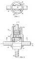
- FIG. 2Aillustrates a side elevation view of an embodiment of the inventive counter-torque wrench in position over a rod engaged in the head of a screw, in accordance with the present invention
- FIG. 2Billustrates an exploded view of an embodiment of the inventive counter-torque wrench in position over a rod engaged in the head of a screw, in accordance with the present invention
- FIG. 3illustrates a perspective view of an embodiment of the rod engaging member in accordance with the disclosed principles, in accordance with the present invention
- FIG. 4illustrates a perspective view of another embodiment of the rod engaging member having a single pocket in each slot, in accordance with the present invention
- FIG. 5illustrates a top view of the rod engaging member and screw body, in accordance with the present invention.
- FIG. 6illustrates a side elevation view of the rod engaging member of the counter-torque wrench in position over the rod engaged with the screw, in accordance with the present invention.
- Counter-torque wrenchesare currently used to help prevent undesired forces from being transmitted to spinal bone screws, thereby minimizing the forces that may otherwise result in the screw breaking through bone as tightening torques are applied.
- the counter-torque wrenches known in the artcan pivot on a rod or otherwise be skewed relative to the rod.
- the known counter-torque wrench 10includes a wrench body 19 that incorporates two straight slots 12 .
- the wrench body 19is operable to be configured with a mating bore that may receive a bone screw assembly, comprised of both a bone screw 16 and a bone screw body 18 , and may also receive a rod 14 .
- the known counter-torque wrench 10can pivot on the rod 14 or be otherwise skewed relative to the rod 14 when engaged with the rod 14 . That is, the longitudinal axis of the wrench body 19 is not always perpendicular to the longitudinal axis of the rod 14 and can be less than 90 degrees, as illustrated by ⁇ in FIGS. 1A and 1B .
- the ability of a set screw (internal, not shown) to efficiently clamp the rod 14is negatively impacted as the set screw and the bone screw assembly may not make flush contact with the rod 14 .
- use of the known counter-torque wrench 10permits the bone screw 16 to rotate out of alignment relative to the rod 14 during tightening if the known counter-torque wrench 10 is levered on during the act of tightening.
- the known counter-torque wrench 10permits the existence of both a gap between the bone screw assembly and the rod 14 and a gap between the rod 14 and the slots 12 and the set screw.
- one embodiment of the inventive counter-torque wrench 20may include a handle 24 which engages a first end 28 of a wrench body 26 .
- the longitudinal axis of the handle 24may be placed perpendicular to the longitudinal axis of the wrench body 26 .
- the longitudinal axis of the handle 24may alternatively be aligned with the longitudinal axis of the wrench body 26 .
- the longitudinal axis of the handle 24may alternatively be oriented at an angle greater than or less than 90 degrees, with respect to the longitudinal axis of the wrench body 26 .
- the handle 24may be integral with or removable from the wrench body 26 in alternative embodiments of the invention.
- the handle 24may even be rotatable around the longitudinal axis of the wrench body 26 .
- the wrench body 26may preferably be tubular.
- “Tubular,” as used herein,means having an inner bore and a wall and having any geometric cross section, including circular, square, hexagonal and the like.
- a tubular wrench body 26may further permit a surgeon to insert a set screw (not shown) and a driver/holder (not shown) through the counter-torque wrench body 26 at an opening 22 if desired.
- the tubular shaped body 26may also enable tools to pass through the wrench body 26 at opening 22 to tighten the set screw, thereby clamping on a rod 44 .
- FIG. 2AAlso shown in FIG. 2A is a rod engaging member 30 disposed on a second end 32 of the wrench body 26 .
- the rod engaging member 30may be tubular in shape having an internal bore (not shown), as discussed in more detail in FIG. 6 .
- the rod engaging member 30may be further configured to fit over a bone screw body 34 of a bone screw assembly, as discussed in more detail in FIG. 2B .
- the rod engaging member 30may further include two slots 36 within the tubular wall of the rod engaging member 30 and spaced opposing each other.
- the two slots 36may advantageously promote a perpendicular orientation between the body of the bone screw body 34 and the rod 44 by incorporating two “L”-shaped slots 36 that are perpendicular to the internal bore (not shown) of the rod engaging member 30 .
- “L”-shaped slots 36forces may be applied to both the wrench body 26 and the rod 44 , thereby promoting perpendicular orientation between the wrench body 26 and the rod 44 when the partial moon cut-out of the “L”-shaped slots 36 engage the rod 44 .
- the inner bore (not shown) of the rod engaging member 30may engage the outside surface of the bone screw body 34 , thereby promoting perpendicular alignment between the bone screw body 34 and the rod 44 .
- a bone screw assembly 35may comprise both the bone screw body 34 and the bone screw 38 and may be configured to receive the rod 44 .
- the bone screw body 34 and the bone screw 38 of the bone screw assembly 35may be manufactured as a single component with a static co-axial orientation between the bone screw body 34 and the bone screw 38 .
- the bone screw body 34 and the bone screw 38 of the bone screw assembly 35may be manufactured from separate components to allow the bone screw 38 to pivotably rotate away from a co-axial alignment with the longitudinal axis of the bone screw body 34 in order to allow the orientation of the longitudinal axis of the bone screw 38 to differ from that of the bone screw body 34 .
- the rod engaging member 30may be configured to be received over the rod 44 and the bone screw assembly 35 and may be rotated counterclockwise to “lock” the rod 44 into the slots in the rod engaging member 30 .
- a set screw 62may be driven through the opening of the wrench body (not shown) and an inner bore of the rod engaging member. As described in more detail in FIG. 6 , the set screw 62 may be engaged with internal threads in the bone screw body 34 , and when the set screw 62 is tightened, the set screw 62 may clamp the rod 44 to the bone screw body 34 .
- the rod engaging member 30may include an internal bore 46 .
- the tubular walls defining the inner bore 46may be perpendicular to the opposing “L”-shaped slots 36 so as to promote the desired perpendicular orientation between the bone screw body (not shown, reference 34 in FIG. 2A ) and the rod (not shown, reference 44 in FIG. 2A ) when the rod is received into the rod engaging member 30 .
- each slot 36 a and 36 bare shown as generally oval in shape defining an opening through which the rod (not shown) may pass in use.
- a curved prong 4040 a and 40 b ) forming a pocket 42 ( 42 a and 42 b ) in which a rod (not shown) may be removably “locked” into position.
- Each curved prong 40defines an “L”-shaped slot 36 , although in other embodiments, the opposing slots 36 could alternatively be described as being “C”-shaped or crescent-shaped, among other shapes.
- Each “L”-shaped slot 36extends substantially vertically from the opening defining the inner bore 46 of the rod engaging member 30 and each prong 40 defines the pocket 42 in slot 36 .
- the exact shape and size of the curved prongs 40 a and 40 bmay vary in various embodiments of the inventive counter-torque wrench provided that each curved prong 40 a and 40 b forms the pockets 42 a and 42 b such that a rod (not shown) may be at least partially held within the pockets 42 a and 42 b in an engaged position when the counter-torque wrench 30 is rotated in a counter-clockwise direction, as discussed in more detail in FIG. 4 .
- the L-shaped slots 36include a curved feature that substantially matches a circumferential curvature of the spinal implant rod.
- the curved prong 40 a of the first slot 36 amay be located opposite the curved prong 40 b of the second slot 36 b . That is, the prongs 40 a and 40 b are not adjacent to each other.
- This alternate placement of the prongs 40 a and 40 ballows the rod engaging member 30 to be placed over a rod (not shown) and “locked” into place by engaging opposing sides of a rod (not shown) in opposite pockets 42 a and 42 b of the rod engaging member 30 .
- the rod 44When the rod 44 is properly engaged and “locked” into place, the rod 44 may be perpendicularly orientated to the wrench body 26 and the bone screw body (not shown).
- each “L”-shaped slot 36may optionally include a straight prong 47 opposite and adjacent to the corresponding curved prong 40 defining the slot 36 .
- FIG. 5further illustrates that internal threads 64 that may be configured to mate with a set screw (not show) received through the internal bore 46 .
- the rod 44is engaged in the “L”-shaped slots 36 , as described in FIGS.
- the internal bore 46 in the wrench body 26engages with an outside diameter of the bone screw body 34 , thereby promoting a co-axial alignment between the wrench body 26 and the bone screw body 34 and a perpendicular orientation between the longitudinal axis of the rod 44 and the longitudinal axis of the bone screw body 34 .
- the set screw 62may be configured to engage with the threads 64 located within the bone screw body 34 in order to clamp the rod 44 perpendicular to the bone screw body 34 .
- the threads 64 shown in FIG. 6are located within an internal wall of the bone screw body 34 such that applying a clockwise torque to the set screw 62 will rotate the set screw 62 downwards against the rod 44 .
- the set screw 62may be engaged with the threads 64 in the bone screw body 34 prior to the counter-torque wrench 20 being engaged with the rod 44 , or the set screw 62 may be inserted through the opening 22 and through the inner bore 46 of the counter-torque wrench 20 , as shown in FIG. 2 . If the set screw 62 is inserted through the opening 22 , the set screw 62 may be passed through the inner bore 46 of the wrench body 26 with the aid of the set screw driver/holder 66 .
- both the bone screw body 34 and the rod 44may be engaged in order to promote a co-axial orientation between the bone screw body 34 and the wrench body 26 and a perpendicular orientation between a longitudinal axis 54 of the wrench body 26 and a longitudinal axis 50 of the rod 44 .
- the surgeonmay first apply counter-torque forces by hand to the counter-torque wrench 20 in a counter-clockwise rotation in order to engage the rod 44 into the slots 36 .
- the surgeonmay apply torque to the set screw 62 , referring back to FIG. 6 , with the set screw driver/holder 66 in a clockwise rotation through the internal bore 46 of the wrench body 26 in order to tighten the set screw 62 .
- the set screw 62may clamp the rod 44 to the bone screw body 34 , thereby promoting a perpendicular orientation between the two.
- the rod engaging member 30 and the bone screw body 34may be sized and oriented to provide a substantially co-linear alignment between the longitudinal axis 54 of the wrench body 26 and the longitudinal axis of the bone screw body 34 .
- the design the bone screw assemblymay allow the bone screw 38 to pivot independently of the bone screw body 34 , thereby allowing a surgeon to pivot the bone screw 38 into proper alignment without changing the orientation of the bone screw body 34 engaged within the internal bore 46 of the counter-torque wrench 20 .
- This functionalitymay allow the surgeon to insert adjacent bone screw assemblies 35 at different orientations in adjacent vertebrae and then connect the bone screw assemblies 35 with the rod 44 via the substantially aligned bone screw bodies 34 such that the rod 44 may be perpendicular to each bone screw body 34 may be connected between the bone screw assemblies 35 .
- each set screw 62may be configured to properly clamp with the connecting rod 44 even if each of the bone screws 38 are inserted into bone at different orientations.
- Proper use of the counter-torque wrench 20may consist of inserting the tool 66 and the set screw 62 through the opening 22 and internal bore 46 of the wrench body 26 onto the rod 44 and the bone screw body 34 to clamp the rod 44 to the bone screw body 34 , as shown in the exploded view of FIG. 2B .
- the counter-torque wrench 20may be configured to be rotated counter-clockwise such that the rod 44 is properly engaged and “locked” into the pockets 42 formed by the prongs 40 defining the “L”-shaped slots 36 on the rod engaging member 30 .
- the “L”-shaped slots 36may aid in aligning the rod 44 in a perpendicular orientation to the bone screw body 34 such that the set screw 62 may make flush contact with the rod 44 .
- the rod 44When properly engaged, the rod 44 is perpendicular to the wrench body 26 and the bone screw body 34 and may prevent inadvertent levering or misalignment of the counter-torque wrench 20 components during final tightening.
- the set screw 62may be tightened more smoothly against the rod 44 by rotating the set screw 62 in a clockwise rotation with the driving tool 66 in order to mate the set screw 62 with the internal threads 64 of the bone screw body 34 . Tightening the set screw 62 clamps the perpendicularly aligned rod 44 against the bone screw body 34 .
- the bone screw body 34When properly oriented perpendicular to the rod 44 , the bone screw body 34 may be less prone to squeaking and galling.
- the rod engaging member 30is generally tubular in shape and has a diameter slightly larger than that of the wrench body 26 . It will be understood that in alternative embodiments, the diameter of the rod engaging member 30 may be equal to or less than the diameter or cross sectional length of the wrench body 26 . In alternative embodiments of the inventive counter-torque wrench, the rod engaging member 30 may be integrally formed with the wrench body 26 or may be removably attached to the wrench body 26 .
- the rod engaging member 30is generally shown to include cutouts between the prongs 40 and 47 which may exist so that rod engaging member 30 can mate with alternative body styles of the bone screw assembly. It will be understood that in alternative embodiments, the cutouts may not be needed and that the only openings in the rod engaging member 30 may be the slots 36 for receiving the rod 44 .
Landscapes
- Health & Medical Sciences (AREA)
- Orthopedic Medicine & Surgery (AREA)
- Neurology (AREA)
- Life Sciences & Earth Sciences (AREA)
- Surgery (AREA)
- Heart & Thoracic Surgery (AREA)
- Engineering & Computer Science (AREA)
- Biomedical Technology (AREA)
- Nuclear Medicine, Radiotherapy & Molecular Imaging (AREA)
- Medical Informatics (AREA)
- Molecular Biology (AREA)
- Animal Behavior & Ethology (AREA)
- General Health & Medical Sciences (AREA)
- Public Health (AREA)
- Veterinary Medicine (AREA)
- Surgical Instruments (AREA)
Abstract
Description
Claims (6)
Priority Applications (2)
| Application Number | Priority Date | Filing Date | Title |
|---|---|---|---|
| US13/196,635US9295501B2 (en) | 2011-08-02 | 2011-08-02 | Bayonet counter-torque wrench |
| PCT/US2012/049180WO2013019873A1 (en) | 2011-08-02 | 2012-08-01 | Bayonet counter-torque wrench |
Applications Claiming Priority (1)
| Application Number | Priority Date | Filing Date | Title |
|---|---|---|---|
| US13/196,635US9295501B2 (en) | 2011-08-02 | 2011-08-02 | Bayonet counter-torque wrench |
Publications (2)
| Publication Number | Publication Date |
|---|---|
| US20130035729A1 US20130035729A1 (en) | 2013-02-07 |
| US9295501B2true US9295501B2 (en) | 2016-03-29 |
Family
ID=47627446
Family Applications (1)
| Application Number | Title | Priority Date | Filing Date |
|---|---|---|---|
| US13/196,635ActiveUS9295501B2 (en) | 2011-08-02 | 2011-08-02 | Bayonet counter-torque wrench |
Country Status (2)
| Country | Link |
|---|---|
| US (1) | US9295501B2 (en) |
| WO (1) | WO2013019873A1 (en) |
Cited By (3)
| Publication number | Priority date | Publication date | Assignee | Title |
|---|---|---|---|---|
| US10820936B2 (en) | 2016-11-04 | 2020-11-03 | Orthopedic Renovation Technologies, Llc | Pedicle screw removal tool and method of use |
| US11191574B2 (en) | 2020-03-17 | 2021-12-07 | Warsaw Orthopedic, Inc. | Set screw reducer for modular reduction screws |
| US11534223B2 (en) | 2016-11-04 | 2022-12-27 | Orthopedic Renovation Technologies, Llc | Pedicle screw removal tool and method of use |
Families Citing this family (8)
| Publication number | Priority date | Publication date | Assignee | Title |
|---|---|---|---|---|
| US8439922B1 (en) | 2008-02-06 | 2013-05-14 | NiVasive, Inc. | Systems and methods for holding and implanting bone anchors |
| US9198698B1 (en) | 2011-02-10 | 2015-12-01 | Nuvasive, Inc. | Minimally invasive spinal fixation system and related methods |
| US20130150905A1 (en)* | 2011-12-09 | 2013-06-13 | Edward Karpowicz | Rod Holder |
| US9486256B1 (en) | 2013-03-15 | 2016-11-08 | Nuvasive, Inc. | Rod reduction assemblies and related methods |
| US9974577B1 (en) | 2015-05-21 | 2018-05-22 | Nuvasive, Inc. | Methods and instruments for performing leveraged reduction during single position spine surgery |
| US10398481B2 (en) | 2016-10-03 | 2019-09-03 | Nuvasive, Inc. | Spinal fixation system |
| US11051861B2 (en) | 2018-06-13 | 2021-07-06 | Nuvasive, Inc. | Rod reduction assemblies and related methods |
| CN110292431B (en)* | 2019-07-24 | 2025-08-08 | 天津正天医疗器械有限公司 | Auxiliary device for fixing connecting rod |
Citations (48)
| Publication number | Priority date | Publication date | Assignee | Title |
|---|---|---|---|---|
| US920188A (en)* | 1908-04-28 | 1909-05-04 | Friedrich Schumacher | Baker's peel. |
| US2337402A (en)* | 1942-08-12 | 1943-12-21 | Cons Vultee Aircraft Corp | Drill chuck |
| US2411245A (en)* | 1944-11-13 | 1946-11-19 | Buechler John Henry | Nut tightener |
| US2987080A (en)* | 1959-06-03 | 1961-06-06 | Wilbur O Chandler | Drain cock tool |
| US3477486A (en) | 1967-10-27 | 1969-11-11 | Henry J Modrey | Ratchet-action tool holder |
| US5505732A (en)* | 1988-06-13 | 1996-04-09 | Michelson; Gary K. | Apparatus and method of inserting spinal implants |
| US5797911A (en) | 1996-09-24 | 1998-08-25 | Sdgi Holdings, Inc. | Multi-axial bone screw assembly |
| US20020120275A1 (en) | 2001-02-26 | 2002-08-29 | Arthrex, Inc. | Torque driver for interference screw |
| US20030105460A1 (en) | 2000-03-15 | 2003-06-05 | Dennis Crandall | Multidirectional pivoting bone screw and fixation system |
| US20030231927A1 (en)* | 2002-06-13 | 2003-12-18 | Electronic Eel Manufacturing Company Inc. | Connector for pipe cleaning apparatus |
| US20040176766A1 (en) | 2002-02-13 | 2004-09-09 | Shluzas Alan E. | Apparatus for connecting a longitudinal member to a bone portion |
| US20040186483A1 (en)* | 2003-03-22 | 2004-09-23 | Bagby George W. | Implant driver apparatus and bone joining device |
| US20040225289A1 (en) | 2003-05-07 | 2004-11-11 | Biedermann Motech Gmbh | Dynamic anchoring device and dynamic stabilization device for bones, in particular for vertebrae, with such an anchoring device |
| US20050043735A1 (en) | 2003-08-21 | 2005-02-24 | Osteomed L.P. | Bone anchor system |
| US20060142762A1 (en)* | 1993-06-10 | 2006-06-29 | Michelson Gary K | Apparatus and method for sequential distraction |
| US20060200131A1 (en) | 2005-03-04 | 2006-09-07 | Depuy Spine Sarl | Constrained motion bone screw assembly |
| US20070043357A1 (en)* | 2005-07-29 | 2007-02-22 | X-Spine Systems, Inc. | Capless multiaxial screw and spinal fixation assembly and method |
| US20070078460A1 (en)* | 2005-08-25 | 2007-04-05 | Robert Frigg | Methods of spinal fixation and instrumentation |
| US20070118123A1 (en) | 2005-11-21 | 2007-05-24 | Strausbaugh William L | Polyaxial bone anchors with increased angulation |
| US20070239159A1 (en) | 2005-07-22 | 2007-10-11 | Vertiflex, Inc. | Systems and methods for stabilization of bone structures |
| US20070281274A1 (en) | 2006-06-05 | 2007-12-06 | Allan Schraffran | Dental wrench and method of use thereof |
| US20080009862A1 (en) | 2006-06-16 | 2008-01-10 | Zimmer Spine, Inc. | Removable polyaxial housing for a pedicle screw |
| US20080147129A1 (en) | 2006-11-17 | 2008-06-19 | Lutz Biedermann | Bone anchoring device |
| US20090076552A1 (en) | 2007-09-17 | 2009-03-19 | Clariance | Vertebral anchoring device |
| US20090198280A1 (en) | 2007-10-24 | 2009-08-06 | Frank Spratt | Assembly for Orthopaedic Surgery |
| US20090281550A1 (en)* | 2006-06-28 | 2009-11-12 | Waldemar Link Gmbh & Co. Kg | Insertion instrument for joint sockets of prostheses |
| US20090306721A1 (en)* | 2008-06-06 | 2009-12-10 | X-Spine Systems, Inc. | Retraction tube for use with capless pedicle screw |
| US20100152785A1 (en) | 2008-12-16 | 2010-06-17 | Abbott Spine Inc. | Coaxially lockable poly-axial bone fastener assemblies |
| US7749258B2 (en) | 2005-10-12 | 2010-07-06 | Biedermann Motech Gmbh | Bone anchoring device |
| US20100212460A1 (en) | 2009-02-24 | 2010-08-26 | Aesculap Implant Systems, Inc. | Expandable counter-torque wrench |
| US20100298891A1 (en) | 2004-11-23 | 2010-11-25 | Jackson Roger P | Bone anchors with longitudinal connecting member engaging inserts and closures for fixation and optional angulation |
| US20100305621A1 (en) | 2009-06-02 | 2010-12-02 | Alphatec Spine, Inc. | Bone screw assembly for limited angulation |
| US20100312288A1 (en) | 2007-05-16 | 2010-12-09 | Hammill Sr John E | Thread-thru polyaxial pedicle screw system |
| US20110077694A1 (en) | 2009-09-25 | 2011-03-31 | Lutz Biedermann | Bone anchoring device |
| US7922725B2 (en)* | 2007-04-19 | 2011-04-12 | Zimmer Spine, Inc. | Method and associated instrumentation for installation of spinal dynamic stabilization system |
| US20110160778A1 (en) | 2009-11-16 | 2011-06-30 | Nexxt Spine, LLC | Poly-Axial Implant Fixation System |
| FR2954689A1 (en)* | 2009-12-28 | 2011-07-01 | Sterispine | DEVICE AND METHOD FOR SPINAL SURGERY. |
| US20110172714A1 (en) | 2008-06-27 | 2011-07-14 | K2M, Inc. | System and method for performing spinal surgery |
| US20110178559A1 (en) | 2010-01-15 | 2011-07-21 | Ebi, Llc | Uniplanar bone anchor system |
| US20110263945A1 (en) | 2010-04-23 | 2011-10-27 | Synthes Usa, Llc | Minimally invasive instrument set, devices and related methods |
| WO2011133160A1 (en) | 2010-04-23 | 2011-10-27 | Synthes Usa, Llc | Spinal surgery instrument sets and methods |
| US20120031792A1 (en)* | 2009-12-28 | 2012-02-09 | Safe Orthopaedics Sas | Instrument kit for performing spinal stabilization |
| US20120046699A1 (en) | 2010-08-20 | 2012-02-23 | K2M, Inc. | Spinal fixation system |
| US8419778B2 (en) | 2010-01-15 | 2013-04-16 | Ebi, Llc | Uniplanar bone anchor system |
| US20130096624A1 (en) | 2010-04-06 | 2013-04-18 | Seaspine, Inc. | System and methods for correcting spinal deformities |
| US20130110176A1 (en) | 2011-11-02 | 2013-05-02 | Warsaw Orthopedic, Inc. | Implant assembly with a rigid interface |
| US20130226243A1 (en) | 2010-04-30 | 2013-08-29 | Kilian Kraus | Pedicle screw and device and method for stabilizing the spinal column |
| US8845651B2 (en)* | 2003-12-08 | 2014-09-30 | DePuy Synthes Products, LLC | Impacting device and method |
- 2011
- 2011-08-02USUS13/196,635patent/US9295501B2/enactiveActive
- 2012
- 2012-08-01WOPCT/US2012/049180patent/WO2013019873A1/enactiveApplication Filing
Patent Citations (52)
| Publication number | Priority date | Publication date | Assignee | Title |
|---|---|---|---|---|
| US920188A (en)* | 1908-04-28 | 1909-05-04 | Friedrich Schumacher | Baker's peel. |
| US2337402A (en)* | 1942-08-12 | 1943-12-21 | Cons Vultee Aircraft Corp | Drill chuck |
| US2411245A (en)* | 1944-11-13 | 1946-11-19 | Buechler John Henry | Nut tightener |
| US2987080A (en)* | 1959-06-03 | 1961-06-06 | Wilbur O Chandler | Drain cock tool |
| US3477486A (en) | 1967-10-27 | 1969-11-11 | Henry J Modrey | Ratchet-action tool holder |
| US5505732A (en)* | 1988-06-13 | 1996-04-09 | Michelson; Gary K. | Apparatus and method of inserting spinal implants |
| US20060142762A1 (en)* | 1993-06-10 | 2006-06-29 | Michelson Gary K | Apparatus and method for sequential distraction |
| US5797911A (en) | 1996-09-24 | 1998-08-25 | Sdgi Holdings, Inc. | Multi-axial bone screw assembly |
| US20030105460A1 (en) | 2000-03-15 | 2003-06-05 | Dennis Crandall | Multidirectional pivoting bone screw and fixation system |
| US20020120275A1 (en) | 2001-02-26 | 2002-08-29 | Arthrex, Inc. | Torque driver for interference screw |
| US20040176766A1 (en) | 2002-02-13 | 2004-09-09 | Shluzas Alan E. | Apparatus for connecting a longitudinal member to a bone portion |
| US20030231927A1 (en)* | 2002-06-13 | 2003-12-18 | Electronic Eel Manufacturing Company Inc. | Connector for pipe cleaning apparatus |
| US20040186483A1 (en)* | 2003-03-22 | 2004-09-23 | Bagby George W. | Implant driver apparatus and bone joining device |
| US20040225289A1 (en) | 2003-05-07 | 2004-11-11 | Biedermann Motech Gmbh | Dynamic anchoring device and dynamic stabilization device for bones, in particular for vertebrae, with such an anchoring device |
| US20050043735A1 (en) | 2003-08-21 | 2005-02-24 | Osteomed L.P. | Bone anchor system |
| US8845651B2 (en)* | 2003-12-08 | 2014-09-30 | DePuy Synthes Products, LLC | Impacting device and method |
| US20100298891A1 (en) | 2004-11-23 | 2010-11-25 | Jackson Roger P | Bone anchors with longitudinal connecting member engaging inserts and closures for fixation and optional angulation |
| US20060200131A1 (en) | 2005-03-04 | 2006-09-07 | Depuy Spine Sarl | Constrained motion bone screw assembly |
| US20070239159A1 (en) | 2005-07-22 | 2007-10-11 | Vertiflex, Inc. | Systems and methods for stabilization of bone structures |
| US20070043357A1 (en)* | 2005-07-29 | 2007-02-22 | X-Spine Systems, Inc. | Capless multiaxial screw and spinal fixation assembly and method |
| US8066745B2 (en)* | 2005-07-29 | 2011-11-29 | X-Spine Systems, Inc. | Capless multiaxial screw and spinal fixation assembly and method |
| US20110152940A1 (en)* | 2005-08-25 | 2011-06-23 | Robert Frigg | Methods of spinal fixation and instrumentation |
| US20070078460A1 (en)* | 2005-08-25 | 2007-04-05 | Robert Frigg | Methods of spinal fixation and instrumentation |
| US7749258B2 (en) | 2005-10-12 | 2010-07-06 | Biedermann Motech Gmbh | Bone anchoring device |
| US20070118123A1 (en) | 2005-11-21 | 2007-05-24 | Strausbaugh William L | Polyaxial bone anchors with increased angulation |
| US20070281274A1 (en) | 2006-06-05 | 2007-12-06 | Allan Schraffran | Dental wrench and method of use thereof |
| US20080009862A1 (en) | 2006-06-16 | 2008-01-10 | Zimmer Spine, Inc. | Removable polyaxial housing for a pedicle screw |
| US20090281550A1 (en)* | 2006-06-28 | 2009-11-12 | Waldemar Link Gmbh & Co. Kg | Insertion instrument for joint sockets of prostheses |
| US20080147129A1 (en) | 2006-11-17 | 2008-06-19 | Lutz Biedermann | Bone anchoring device |
| US7922725B2 (en)* | 2007-04-19 | 2011-04-12 | Zimmer Spine, Inc. | Method and associated instrumentation for installation of spinal dynamic stabilization system |
| US20100312288A1 (en) | 2007-05-16 | 2010-12-09 | Hammill Sr John E | Thread-thru polyaxial pedicle screw system |
| US20090076552A1 (en) | 2007-09-17 | 2009-03-19 | Clariance | Vertebral anchoring device |
| US8430914B2 (en) | 2007-10-24 | 2013-04-30 | Depuy Spine, Inc. | Assembly for orthopaedic surgery |
| US20090198280A1 (en) | 2007-10-24 | 2009-08-06 | Frank Spratt | Assembly for Orthopaedic Surgery |
| US20090306721A1 (en)* | 2008-06-06 | 2009-12-10 | X-Spine Systems, Inc. | Retraction tube for use with capless pedicle screw |
| US8142436B2 (en)* | 2008-06-06 | 2012-03-27 | X-Spine Systems, Inc. | Retraction tube for use with bone screw |
| US20110172714A1 (en) | 2008-06-27 | 2011-07-14 | K2M, Inc. | System and method for performing spinal surgery |
| US20100152785A1 (en) | 2008-12-16 | 2010-06-17 | Abbott Spine Inc. | Coaxially lockable poly-axial bone fastener assemblies |
| US20100212460A1 (en) | 2009-02-24 | 2010-08-26 | Aesculap Implant Systems, Inc. | Expandable counter-torque wrench |
| US20100305621A1 (en) | 2009-06-02 | 2010-12-02 | Alphatec Spine, Inc. | Bone screw assembly for limited angulation |
| US20110077694A1 (en) | 2009-09-25 | 2011-03-31 | Lutz Biedermann | Bone anchoring device |
| US20110160778A1 (en) | 2009-11-16 | 2011-06-30 | Nexxt Spine, LLC | Poly-Axial Implant Fixation System |
| FR2954689A1 (en)* | 2009-12-28 | 2011-07-01 | Sterispine | DEVICE AND METHOD FOR SPINAL SURGERY. |
| US20120031792A1 (en)* | 2009-12-28 | 2012-02-09 | Safe Orthopaedics Sas | Instrument kit for performing spinal stabilization |
| US20110178559A1 (en) | 2010-01-15 | 2011-07-21 | Ebi, Llc | Uniplanar bone anchor system |
| US8419778B2 (en) | 2010-01-15 | 2013-04-16 | Ebi, Llc | Uniplanar bone anchor system |
| US20130096624A1 (en) | 2010-04-06 | 2013-04-18 | Seaspine, Inc. | System and methods for correcting spinal deformities |
| WO2011133160A1 (en) | 2010-04-23 | 2011-10-27 | Synthes Usa, Llc | Spinal surgery instrument sets and methods |
| US20110263945A1 (en) | 2010-04-23 | 2011-10-27 | Synthes Usa, Llc | Minimally invasive instrument set, devices and related methods |
| US20130226243A1 (en) | 2010-04-30 | 2013-08-29 | Kilian Kraus | Pedicle screw and device and method for stabilizing the spinal column |
| US20120046699A1 (en) | 2010-08-20 | 2012-02-23 | K2M, Inc. | Spinal fixation system |
| US20130110176A1 (en) | 2011-11-02 | 2013-05-02 | Warsaw Orthopedic, Inc. | Implant assembly with a rigid interface |
Non-Patent Citations (5)
| Title |
|---|
| International Search Report and Written Opinion, PCT/US2012/049180, dated Oct. 26, 2012, 9 pages. |
| International Search Report and Written Opinion, PCT/US2014/061293, dated Jan. 23, 2015, 12 pages. |
| U.S. Office Action, U.S. Appl. No. 14/037,011, dated Jun. 5, 2015, 30 pages. |
| U.S. Office Action, U.S. Appl. No. 14/059,203, dated May 18, 2015, 46 pages. |
| U.S. Office Action, U.S. Appl. No. 14/092,154, dated Dec. 24, 2015, 11 pages. |
Cited By (3)
| Publication number | Priority date | Publication date | Assignee | Title |
|---|---|---|---|---|
| US10820936B2 (en) | 2016-11-04 | 2020-11-03 | Orthopedic Renovation Technologies, Llc | Pedicle screw removal tool and method of use |
| US11534223B2 (en) | 2016-11-04 | 2022-12-27 | Orthopedic Renovation Technologies, Llc | Pedicle screw removal tool and method of use |
| US11191574B2 (en) | 2020-03-17 | 2021-12-07 | Warsaw Orthopedic, Inc. | Set screw reducer for modular reduction screws |
Also Published As
| Publication number | Publication date |
|---|---|
| WO2013019873A1 (en) | 2013-02-07 |
| US20130035729A1 (en) | 2013-02-07 |
Similar Documents
| Publication | Publication Date | Title |
|---|---|---|
| US9295501B2 (en) | Bayonet counter-torque wrench | |
| US10617448B2 (en) | Variable angle spinal screw assembly with press fitment bushing | |
| JP7290762B2 (en) | Medical instrument for temporary fastening of polyaxial pedicle screws | |
| US9585698B2 (en) | Polyaxial bone anchoring device | |
| EP1893110B1 (en) | Adjustable fixation clamp | |
| JP3307428B2 (en) | Device for straightening, fixing, compressing or stretching the spine | |
| US10869699B2 (en) | Rod link reducer | |
| US20100004694A1 (en) | Screw assembly | |
| US20080294202A1 (en) | Bone Anchor With Locking Cap and Method of Spinal Fixation | |
| US20060025768A1 (en) | Top loading spinal fixation device and instruments for loading and handling the same | |
| US20120283787A1 (en) | Pedicle screws and methods of use | |
| JP2012196453A (en) | Polyaxial pedicle screw and fixation system kit comprising the same | |
| JPH0739808U (en) | Fixator for posterior spinal correction | |
| TW201309256A (en) | Polyaxial bone anchoring device with enlarged pivot angle | |
| US20070227309A1 (en) | Hose Clamp Tool | |
| US12245778B2 (en) | Minimally invasive displacement osteotomy system and method |
Legal Events
| Date | Code | Title | Description |
|---|---|---|---|
| AS | Assignment | Owner name:BLACKSTONE MEDICAL, INC., TEXAS Free format text:ASSIGNMENT OF ASSIGNORS INTEREST;ASSIGNOR:HAMMER, MICHAEL A.;REEL/FRAME:026691/0888 Effective date:20110727 | |
| AS | Assignment | Owner name:JPMORGAN CHASE BANK, N.A., AS ADMINISTRATIVE AGENT Free format text:SECURITY INTEREST;ASSIGNOR:BLACKSTONE MEDICAL, INC.;REEL/FRAME:036682/0192 Effective date:20150831 | |
| STCF | Information on status: patent grant | Free format text:PATENTED CASE | |
| MAFP | Maintenance fee payment | Free format text:PAYMENT OF MAINTENANCE FEE, 4TH YEAR, LARGE ENTITY (ORIGINAL EVENT CODE: M1551); ENTITY STATUS OF PATENT OWNER: LARGE ENTITY Year of fee payment:4 | |
| AS | Assignment | Owner name:JPMORGAN CHASE BANK, N.A., ILLINOIS Free format text:SECURITY INTEREST;ASSIGNOR:ORTHOFIX SPINAL IMPLANTS INC.;REEL/FRAME:050839/0856 Effective date:20191025 | |
| AS | Assignment | Owner name:ORTHOFIX SPINAL IMPLANTS INC., TEXAS Free format text:CHANGE OF NAME;ASSIGNOR:BLACKSTONE MEDICAL, INC.;REEL/FRAME:054458/0045 Effective date:20181221 | |
| AS | Assignment | Owner name:ORTHOFIX HOLDINGS, INC., TEXAS Free format text:MERGER;ASSIGNOR:ORTHOFIX SPINAL IMPLANTS INC.;REEL/FRAME:055002/0751 Effective date:20201230 Owner name:ORTHOFIX INC., TEXAS Free format text:MERGER;ASSIGNOR:ORTHOFIX HOLDINGS, INC.;REEL/FRAME:055002/0841 Effective date:20201230 | |
| AS | Assignment | Owner name:JPMORGAN CHASE BANK, N.A., AS ADMINISTRATIVE ASSISTANT, ILLINOIS Free format text:SECURITY INTEREST;ASSIGNOR:ORTHOFIX US LLC;REEL/FRAME:056000/0153 Effective date:20210420 | |
| AS | Assignment | Owner name:ORTHOFIX US LLC, TEXAS Free format text:ENTITY CONVERSION;ASSIGNOR:ORTHOFIX INC.;REEL/FRAME:057247/0265 Effective date:20201231 | |
| MAFP | Maintenance fee payment | Free format text:PAYMENT OF MAINTENANCE FEE, 8TH YEAR, LARGE ENTITY (ORIGINAL EVENT CODE: M1552); ENTITY STATUS OF PATENT OWNER: LARGE ENTITY Year of fee payment:8 | |
| AS | Assignment | Owner name:ORTHOFIX SPINAL IMPLANTS INC., TEXAS Free format text:RELEASE BY SECURED PARTY;ASSIGNOR:JPMORGAN CHASE BANK, N.A.;REEL/FRAME:065609/0247 Effective date:20231106 Owner name:ORTHOFIX US LLC, TEXAS Free format text:RELEASE BY SECURED PARTY;ASSIGNOR:JPMORGAN CHASE BANK, N.A.;REEL/FRAME:065609/0223 Effective date:20231106 | |
| AS | Assignment | Owner name:BLUE TORCH FINANCE LLC, AS COLLATERAL AGENT, NEW YORK Free format text:SECURITY INTEREST;ASSIGNOR:ORTHOFIX US LLC;REEL/FRAME:066256/0423 Effective date:20231106 | |
| AS | Assignment | Owner name:OXFORD FINANCE LLC, AS AGENT, VIRGINIA Free format text:SECURITY INTEREST;ASSIGNORS:ORTHOFIX MEDICAL INC.;ORTHOFIX US LLC;SPINAL KINETICS LLC;AND OTHERS;REEL/FRAME:069332/0761 Effective date:20241107 | |
| AS | Assignment | Owner name:THEKEN SPINE, LLC, CALIFORNIA Free format text:RELEASE BY SECURED PARTY;ASSIGNOR:BLUE TORCH FINANCE LLC;REEL/FRAME:069358/0110 Effective date:20241111 Owner name:SPINAL KINETICS LLC, CALIFORNIA Free format text:RELEASE BY SECURED PARTY;ASSIGNOR:BLUE TORCH FINANCE LLC;REEL/FRAME:069358/0110 Effective date:20241111 Owner name:SEASPINE ORTHOPEDICS CORPORATION, CALIFORNIA Free format text:RELEASE BY SECURED PARTY;ASSIGNOR:BLUE TORCH FINANCE LLC;REEL/FRAME:069358/0110 Effective date:20241111 Owner name:SEASPINE, INC., CALIFORNIA Free format text:RELEASE BY SECURED PARTY;ASSIGNOR:BLUE TORCH FINANCE LLC;REEL/FRAME:069358/0110 Effective date:20241111 Owner name:ORTHOFIX US, LLC, TEXAS Free format text:RELEASE BY SECURED PARTY;ASSIGNOR:BLUE TORCH FINANCE LLC;REEL/FRAME:069358/0110 Effective date:20241111 Owner name:ISOTIS ORTHOBIOLOGICS, INC., CALIFORNIA Free format text:RELEASE BY SECURED PARTY;ASSIGNOR:BLUE TORCH FINANCE LLC;REEL/FRAME:069358/0110 Effective date:20241111 |