US9295449B2 - Landmarks for ultrasound imaging - Google Patents
Landmarks for ultrasound imagingDownload PDFInfo
- Publication number
- US9295449B2 US9295449B2US13/748,432US201313748432AUS9295449B2US 9295449 B2US9295449 B2US 9295449B2US 201313748432 AUS201313748432 AUS 201313748432AUS 9295449 B2US9295449 B2US 9295449B2
- Authority
- US
- United States
- Prior art keywords
- location
- information
- image plane
- orientation
- ultrasound
- Prior art date
- Legal status (The legal status is an assumption and is not a legal conclusion. Google has not performed a legal analysis and makes no representation as to the accuracy of the status listed.)
- Active, expires
Links
Images


Classifications
- A—HUMAN NECESSITIES
- A61—MEDICAL OR VETERINARY SCIENCE; HYGIENE
- A61B—DIAGNOSIS; SURGERY; IDENTIFICATION
- A61B8/00—Diagnosis using ultrasonic, sonic or infrasonic waves
- A61B8/42—Details of probe positioning or probe attachment to the patient
- A61B8/4245—Details of probe positioning or probe attachment to the patient involving determining the position of the probe, e.g. with respect to an external reference frame or to the patient
- A61B8/4263—Details of probe positioning or probe attachment to the patient involving determining the position of the probe, e.g. with respect to an external reference frame or to the patient using sensors not mounted on the probe, e.g. mounted on an external reference frame
- A—HUMAN NECESSITIES
- A61—MEDICAL OR VETERINARY SCIENCE; HYGIENE
- A61B—DIAGNOSIS; SURGERY; IDENTIFICATION
- A61B10/00—Instruments for taking body samples for diagnostic purposes; Other methods or instruments for diagnosis, e.g. for vaccination diagnosis, sex determination or ovulation-period determination; Throat striking implements
- A61B10/02—Instruments for taking cell samples or for biopsy
- A61B10/0233—Pointed or sharp biopsy instruments
- A—HUMAN NECESSITIES
- A61—MEDICAL OR VETERINARY SCIENCE; HYGIENE
- A61B—DIAGNOSIS; SURGERY; IDENTIFICATION
- A61B8/00—Diagnosis using ultrasonic, sonic or infrasonic waves
- A61B8/08—Clinical applications
- A61B8/0833—Clinical applications involving detecting or locating foreign bodies or organic structures
- A61B8/0841—Clinical applications involving detecting or locating foreign bodies or organic structures for locating instruments
- A—HUMAN NECESSITIES
- A61—MEDICAL OR VETERINARY SCIENCE; HYGIENE
- A61B—DIAGNOSIS; SURGERY; IDENTIFICATION
- A61B8/00—Diagnosis using ultrasonic, sonic or infrasonic waves
- A61B8/42—Details of probe positioning or probe attachment to the patient
- A61B8/4245—Details of probe positioning or probe attachment to the patient involving determining the position of the probe, e.g. with respect to an external reference frame or to the patient
- A61B8/4254—Details of probe positioning or probe attachment to the patient involving determining the position of the probe, e.g. with respect to an external reference frame or to the patient using sensors mounted on the probe
- A—HUMAN NECESSITIES
- A61—MEDICAL OR VETERINARY SCIENCE; HYGIENE
- A61B—DIAGNOSIS; SURGERY; IDENTIFICATION
- A61B8/00—Diagnosis using ultrasonic, sonic or infrasonic waves
- A61B8/46—Ultrasonic, sonic or infrasonic diagnostic devices with special arrangements for interfacing with the operator or the patient
- A61B8/461—Displaying means of special interest
- A61B8/463—Displaying means of special interest characterised by displaying multiple images or images and diagnostic data on one display
- A61B19/56—
- A—HUMAN NECESSITIES
- A61—MEDICAL OR VETERINARY SCIENCE; HYGIENE
- A61B—DIAGNOSIS; SURGERY; IDENTIFICATION
- A61B17/00—Surgical instruments, devices or methods
- A61B17/34—Trocars; Puncturing needles
- A61B17/3403—Needle locating or guiding means
- A61B2017/3413—Needle locating or guiding means guided by ultrasound
- A61B2019/507—
- A61B2019/5276—
- A61B2019/5287—
- A—HUMAN NECESSITIES
- A61—MEDICAL OR VETERINARY SCIENCE; HYGIENE
- A61B—DIAGNOSIS; SURGERY; IDENTIFICATION
- A61B34/00—Computer-aided surgery; Manipulators or robots specially adapted for use in surgery
- A61B34/10—Computer-aided planning, simulation or modelling of surgical operations
- A61B2034/107—Visualisation of planned trajectories or target regions
- A—HUMAN NECESSITIES
- A61—MEDICAL OR VETERINARY SCIENCE; HYGIENE
- A61B—DIAGNOSIS; SURGERY; IDENTIFICATION
- A61B90/00—Instruments, implements or accessories specially adapted for surgery or diagnosis and not covered by any of the groups A61B1/00 - A61B50/00, e.g. for luxation treatment or for protecting wound edges
- A61B90/36—Image-producing devices or illumination devices not otherwise provided for
- A61B2090/363—Use of fiducial points
- A—HUMAN NECESSITIES
- A61—MEDICAL OR VETERINARY SCIENCE; HYGIENE
- A61B—DIAGNOSIS; SURGERY; IDENTIFICATION
- A61B90/00—Instruments, implements or accessories specially adapted for surgery or diagnosis and not covered by any of the groups A61B1/00 - A61B50/00, e.g. for luxation treatment or for protecting wound edges
- A61B90/36—Image-producing devices or illumination devices not otherwise provided for
- A61B90/37—Surgical systems with images on a monitor during operation
- A61B2090/378—Surgical systems with images on a monitor during operation using ultrasound
- A—HUMAN NECESSITIES
- A61—MEDICAL OR VETERINARY SCIENCE; HYGIENE
- A61B—DIAGNOSIS; SURGERY; IDENTIFICATION
- A61B34/00—Computer-aided surgery; Manipulators or robots specially adapted for use in surgery
- A61B34/25—User interfaces for surgical systems
- A—HUMAN NECESSITIES
- A61—MEDICAL OR VETERINARY SCIENCE; HYGIENE
- A61B—DIAGNOSIS; SURGERY; IDENTIFICATION
- A61B8/00—Diagnosis using ultrasonic, sonic or infrasonic waves
- A61B8/13—Tomography
- A61B8/14—Echo-tomography
- A—HUMAN NECESSITIES
- A61—MEDICAL OR VETERINARY SCIENCE; HYGIENE
- A61B—DIAGNOSIS; SURGERY; IDENTIFICATION
- A61B8/00—Diagnosis using ultrasonic, sonic or infrasonic waves
- A61B8/46—Ultrasonic, sonic or infrasonic diagnostic devices with special arrangements for interfacing with the operator or the patient
- A61B8/467—Ultrasonic, sonic or infrasonic diagnostic devices with special arrangements for interfacing with the operator or the patient characterised by special input means
- A61B8/469—Ultrasonic, sonic or infrasonic diagnostic devices with special arrangements for interfacing with the operator or the patient characterised by special input means for selection of a region of interest
- A—HUMAN NECESSITIES
- A61—MEDICAL OR VETERINARY SCIENCE; HYGIENE
- A61B—DIAGNOSIS; SURGERY; IDENTIFICATION
- A61B8/00—Diagnosis using ultrasonic, sonic or infrasonic waves
- A61B8/52—Devices using data or image processing specially adapted for diagnosis using ultrasonic, sonic or infrasonic waves
- A61B8/5292—Devices using data or image processing specially adapted for diagnosis using ultrasonic, sonic or infrasonic waves using additional data, e.g. patient information, image labeling, acquisition parameters
Definitions
- This inventionrelates to medical imaging.
- the inventionrelates specifically to methods and apparatus for guiding biopsy devices or other tools to locations within the body of a patient.
- the inventionhas particular application to ultrasound-guided biopsy planning, guiding, brachytherapy and the like.
- biopsy samplestissue samples
- a physicianmay take biopsies at a number of locations within the prostate. These biopsy samples may be analyzed in a lab to allow medical professionals to better understand the state of the patient's health and also to allow the medical professionals to plan a treatment, where necessary.
- Some treatments for cancer and other tumoursinvolve placing small radioactive seeds or other objects in the body near the locations of the tumours.
- Brachytherapyis one example of such treatment.
- brachytherapyit is desirable to plant the seeds in locations such that, as much as possible, tumours are irradiated while normal tissues surrounding the tumours are spared.
- Example aspects of the inventionprovide ultrasound machines, systems for guided placement of medical tools for example, biopsy needles, devices for introducing brachytherapy seeds and other objects into a subject and the like, systems for facilitating guided return of a tool to a previously recorded location in a subject, systems for displaying guidance information for a surgical tool, methods for guided placement of medical tools, methods for guiding return of a tool to a previously recorded location in a subject, methods for displaying guidance information for a surgical tool, computer program products carrying machine-readable instructions for causing a data processor to control execution of a method or part thereof as described herein, and the like.
- One aspect of the inventionapplies 2D images which include indicia to indicate 3D locations.
- Combinations of graphic attributessuch as color, size, shape, brightness and transparency of the indicia are controlled to display information representing 3D locations in 2D images.
- Another aspect of the inventionapplies fiducial locations to provide location tracking mechanisms that are independent of the relative positions of a patient and a tracking system base unit.
- Another aspect of the inventionprovides systems and methods for recording in real time the locations at which interventions are performed on a patient (examples of interventions are taking biopsy samples, placing seeds or other objects in the patient, and the like).
- ultrasound imaging apparatuscomprising: an ultrasound probe configured to transmit ultrasound signals and to receive ultrasound echo signals and an ultrasound system configured to process the ultrasound echo signals to yield a two-dimensional ultrasound image representing an image plane within a subject.
- a displayis connected to display the ultrasound image.
- a position-sensing systemis configured to monitor a position and orientation of the ultrasound probe in a coordinate system to yield probe position and orientation information.
- a processoris configured to: process the probe position and orientation information to determine: a display location in the ultrasound image corresponding to a perpendicular projection of a predetermined location onto the image plane and a distance between the predetermined location and the image plane; and superimpose on the ultrasound image on the display location marking indicia at the display location and having one or more appearance characteristics determined at least in part by the distance between the predetermined location and the image plane.
- the apparatuscomprises a processor.
- the processoris configured to receive first information indicating the location and orientation of the ultrasound probe and to determine, based on the first information, second information indicating the location and orientation of a 2D region within the body of the patient scanned by the ultrasound probe.
- the processoris configured to receive third information indicating the location of the selected point and to determine, based the second and third information fourth information indicating whether or not the selected point lies within the 2D region.
- the processoris configured to set location and appearance of indicia on a display based on the fourth information.
- FIG. 1illustrates schematically a system according to an example embodiment.
- FIG. 2is a vector diagram illustrating an example method for determining location and orientation of a probe sensor and other tracked components.
- FIGS. 3 and 4are charts that illustrate example ways in which the color and/or size of a marker indicating a location in an image may be controlled to indicate the distance between the location and the image plane and the current side of the image plane on which the location is currently sited.
- FIGS. 5A, 5B and 5Cillustrate marking locations in an image based on position of a guided tool, position of a tracked free-hand tool and by direct marking on the image.
- FIG. 6schematically shows an example image which includes a portion of an organ and marked locations for acquiring biopsy samples.
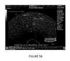
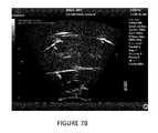
- FIGS. 7A , B, and Cshow example images overlaid with indicia indicating the locations of a number of points relative to an imaging plane.
- FIG. 7Dillustrates the geometry of FIG. 7A .
- FIG. 8is a flowchart illustrating one method of use of a system according to an embodiment of the invention.
- FIG. 9is a flowchart illustrating a method according to another embodiment.
- FIG. 10is a flowchart illustrating a method according to another embodiment.
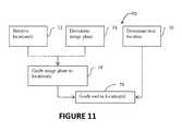
- FIG. 11is a flowchart illustrating a method according to another embodiment.
- FIG. 1illustrates schematically a system 10 according to an example embodiment.
- System 10is being used to investigate a patient P.
- An ultrasound imaging system 12has a probe 14 that sends ultrasound energy into patient P and receives echo signals from within patient P.
- the echo signalsare processed by ultrasound system 12 to yield images 17 that are displayed on a display 18 .
- Ultrasound system 12may have any suitable construction. A wide range of ultrasound systems capable of generating images of structures within a patient are commercially available. Ultrasound system 12 may, for example, be or operate like such commercially-available systems.
- Image 17may be a 2D image representing a slice through a portion of patient P.
- image 17may comprise a B-mode image.
- the particular location and orientation of the plane imaged by image 17is determined by the location and orientation of probe 14 relative to the patient P.
- Image 17may be refreshed in real time such that a user can readily select a desired imaging plane by moving probe 14 and watching the resulting image 17 .
- Ultrasound machine 12may have a user interface 16 which allows the user to select imaging modes and/or parameters affecting the imaging modes to achieve a desired image display on display 18 .
- System 10includes a 3D location system 20 which comprises a base unit 22 , a sensor 23 embedded in probe 14 , and an optional fiducial sensor 26 .
- Fiducial sensor 26when present, may be applied at a fixed location on the subject patient P. Where base unit 22 is or can be placed at a known position and orientation relative to patient P then a separate fiducial sensor 26 is not required. In such cases, base unit 22 can be considered to be the fiducial sensor 26 .
- System 20may operate according to any of a wide number of principles.
- system 20uses magnetic fields to monitor the location and orientation of the sensor 23 in the probe 14 and the fiducial sensor 26 .
- Various 6-degree-of freedom (6DOF) location systemsare commercially available. One of these systems may, for example, be applied as 3D location system 20 .
- system 10incorporates a fiducial sensor 26 .
- Fiducial sensor 26may be removably affixed at a known location on patient P.
- System 20detects the location and orientation of fiducial sensor 26 relative to base unit 22 .
- System 20can therefore determine the positions and orientations of other sensors relative to fiducial sensor 26 .
- base unit 22can be freely moved around the patient P without affecting the ability of system 20 to track positions and orientations of other sensors relative to fiducial sensor 26 . It is convenient but not mandatory that fiducial sensor 26 be affixed at the same spot on patient P for different study sessions.
- Image 17relates to a plane which has a known orientation relative to probe 14 and each location (e.g. each pixel) in image 17 corresponds to a known location in the image plane relative to probe 14 (the locations in the image plane that correspond to pixels in image 17 may change depending on the imaging mode).
- system 20may determine the location and orientation of the probe sensor 23 as vector V 23 and the location and orientation of fiducial sensor 26 as vector V 26 relative to base unit 22 .
- Any location L in the present imaging plane of the probe 14can then be derived by the ultrasound system 12 from vector V 23 and the vector V 24 between the point corresponding to location L and a reference location on the probe sensor 23 .
- the sum of these vectors, shown as vector V relative to the base unit 22may be further transformed to provide a vector V 25 indicating the position of location L relative to the location of fiducial sensor 26 using the known vector V 26 .
- Vector V 25indicates the position of location L relative to fiducial sensor 26 .
- Information identifying one or more locationsmay be stored for future reference. Such information may, for example, be applied to guide a tool to the location in future and/or to obtain an ultrasound image in the same plane relative to patient P as a current ultrasound image.
- the information storedmay comprise, for example, vector V 25 corresponding to one or more locations L.
- the stored informationmay also comprise stored fiducial data (e.g. vector V 26 ).
- locationsare initially stored in memory and then saved to files in a data store for subsequent reloading.
- System 20may track the position of a location L relative to the imaging plane of probe 23 .
- probe 23 and its imaging planemay be moving relative to base unit 22 .
- the relative locations of base unit 22 and fiducial sensor 26may also be changing.
- System 20may be configured to update a vector V 25 ′ indicating the position of a location L relative to fiducial sensor 26 (located at a current position V 26 ′) by applying spatial transformations (which may comprise rotations and/or translations) to vector V 25 .
- Vector V 25 ′may be converted back to a vector V′ indicating the current position of location L relative to base unit 22 , and then this current position of location L may be projected perpendicularly to the current imaging plane as L′.
- the systemmay display an indicia at a location in the image corresponding to L′.
- the indiciaidentifies the location L′ in the image which indicates the perpendicular projection of location L into the current image plane.
- the indiciamay be displayed with different colors, sizes, shapes and/or brightness.
- the indiciawhen the image plane is positioned and oriented such that location L falls in the imaging plane, the indicia may comprise a large green icon or other marker. While location L is out of the image plane in the near field (i.e. on a front side of the image plane), the color of the marker may be gradually mixed with blue with the amount of blue determined by the distance of location L from the image plane. The marker may be displayed as being pure blue at a threshold distance. In some embodiments the threshold distance is a maximum viewing depth. While location L is out of the image plane in the far field (i.e. on a rear side of the image plane), the color of the marker may be mixed with red. The amount of red may be determined by the distance of location L from the image plane. The marker may be displayed in a pure red color when location L is at a threshold distance out of the image plane.
- Colors other than green, blue and redmay be used in alternative example embodiments.
- some embodimentsare similar to the embodiment described above except that green, blue and red are respectively replaced with a first color, a second color and a third color (where the first, second and third colors are any three distinguishable colors).
- Characteristics other than color and sizemay be varied instead of or in addition to color and/or size. Other characteristics that may be varied include, for example, brightness, line thickness (width), line pattern, and the like.
- the size of the markermay also be varied based on the distance of location L from the image plane. For example, the marker may be made smaller with increasing distance from the image plane on either side of the image plane.
- FIGS. 3 and 4are charts that illustrate example ways in which the color and/or size of a marker indicating location L may be controlled to indicate the distance between location L and the image plane and the side of the image plane on which location L is currently.
- the markersmay, for example, comprise shapes.
- the shapesare un-filled in some embodiments.
- the shapesare simple geometric shapes such as circles, squares or triangles.
- System 10may provide the ability to record the precise locations at which biopsy samples are taken. For example, the triggering of a biopsy device (e.g. tool 24 ) to remove a biopsy sample from patient P may automatically generate a signal that causes one or more positions indicative of the location from which the biopsy sample was extracted (as determined by position monitoring system 20 ) to be preserved in a memory.
- a separate controlsuch as a foot pedal or button may be provided to allow the physician to signal when the surgical tool 24 is in the location at which the surgeon intends to operate or has operated the tool 24 to extract a biopsy sample.
- the location at which a biopsy sample is takenmay be determined by directly measuring the position (for example by tracking the position of a surgical tool used to acquire the biopsy sample with system 20 or by using a surgical tool with a guide which places the surgical tool at a known location relative to a sensor being tracked by position sensing system 20 .
- system 10comprises a surgical tool 24 , which might be a biopsy guide, or a tracking sensor enabled needle.
- a biopsy guidemay be mounted to probe 14 such that there is a known relationship between the probe 14 (hence sensor 23 ) and the location where a biopsy sample will be withdrawn into the tool.
- the biopsy guidemay be arranged such that the location at which the biopsy sample is taken is in an imaging plane of the images acquired by probe 14 . From the known relationship between the biopsy location and probe 14 (as determined by the biopsy guide) the location of the actual biopsy site relative to the fiducial sensor 26 can be calculated and recorded.
- a tool used to acquire a biopsy samplecomprises a needle with a tracking sensor which is monitored by position sensing system 20
- the location of the actual biopsy site relative to the tracking sensor of the needleis known from the construction of the needle.
- the location of the actual biopsy site relative to fiducial sensor 26can be determined in a manner similar to that illustrated in FIG. 2 .
- Embodimentsmay be provided which permit locations of biopsy samples or other operations to be recorded in one or more of several different ways. Such embodiments may be used to record exactly where biopsy samples have been taken. For example, where samples are taken with a tool guided by a biopsy guide, a physician may cause apparatus to record a biopsy location with one single push on a button or a footpad. Such a control input may record a location of the biopsy sample and cause display of a marker at a location where the guide causes the biopsy sample to be taken, as shown for example in FIG. 5A . Where the biopsy sample is acquired by a needle or other biopsy devices equipped with tracking sensor, the control input (e.g. push of a button or pedal) will record a location of the tip of the needle and mark that location as illustrated for example in FIG.
- the control inpute.g. push of a button or pedal
- the physicianmay use a user interface to manually mark a biopsy location in the current image plane. 3D coordinates of this location may be stored. Markers indicating the location may be shown as illustrated for example in FIG. 5C .
- 3D location system 20 and ultrasound system 12allows determination of the location and orientation of points in the image plane and biopsy sites from various surgical tools 24 all relative to the fiducial sensor 26 .
- the positions of recorded locations relative to the fiducial sensor 26can then be projected perpendicularly back on the active imaging plane as the relative relationship of the sensor 26 and probe sensor 23 is tracked by the system 20 .
- the system 10permits the 3-dimensional locations within patient P to be represented in the 2D image 17 intuitively with different colors, sizes, shapes and/or brightness etc.
- system 10comprises a programmed data processor that receives position data from 3D location system 20 and determines the 3-dimensional location within patient P of pixels of image 17 as well as the location of surgical tool 24 relative to the current image plane.
- the data processormay be a separate stand-alone data processor or may be integrated with 3D location sensing system 20 or ultrasound system 12 or some other component of system 10 , for example.
- a physicianmay remove a number of biopsy samples from a particular organ.
- a typical prostate biopsymay involve the taking of several biopsy samples.
- a biopsy of the prostatemay involve taking from a few biopsy samples to about 25 or so biopsy samples.
- the samplesmay each be taken at a different location within the prostate (or other organ being studied).
- System 20may be operated to obtain information relevant to the locations at which each of these biopsy samples was acquired.
- System 10may record this information to permit: the biopsy sites to be identified in future imaging; future biopsies to be taken at or near the same locations where the biopsies were taken; brachytherapy seeds or other objects to be inserted at the location at which a biopsy sample was acquired, etc.
- a system 10may assist in planning an array of locations from which biopsy samples may be taken. For example, the system may calculate locations in three dimensions of an array of points for taking biopsy samples. In some embodiments, the array of locations may be determined relative to an initial location of tool 24 . For example, a physician may insert tool 24 to a location at which it is desired to take a first biopsy sample. System 10 may then compute an array of points which are spaced apart from that initial location. In some embodiments, system 10 detects the boundaries of an organ within which the biopsy samples are to be taken (for example, by detecting edges of the organ in image data) and determines locations for taking biopsy samples that are evenly spread out throughout the organ or spread throughout the organ in a predetermined manner.
- FIG. 6shows an image which includes a portion of an organ S.
- System 10has computed locations 27 corresponding to suggested locations for acquiring biopsy samples and has added markers indicating those locations to image 17 .
- the recorded locations at which the biopsy samples were takenmay be used subsequently to guide a user to return to the location(s) at which any or all of the biopsy samples were taken.
- One example of a situation in which this may be desirableapplies to the case where laboratory investigations of one or more biopsy samples find that tissue is abnormal. It may be decided to implant a brachytherapy seed or implanted drug-dispenser at the location of the particular biopsy sample.
- System 10may be used to guide the user back to the same location from which the biopsy sample was taken. In this case, the user may be using a tool which permits implantation of a brachytherapy seed or other object at that location. As another example, it may be desirable to repeat a biopsy at a subsequent time to recheck results of an earlier biopsy.
- System 10may incorporate novel systems and methods for one or both of indicating the relationship between the current location and orientation of the imaging plane and one or more predefined locations within a patient; and indicating the relationship of the current location and orientation of a surgical tool, such as a biopsy probe to such predefined locations.
- a usermay use these systems and methods in order to one or both: move probe 14 such that the imaging plane passes through a previously determined location in the patient; and insert a surgical tool 24 to interact with that previously determined location. It may be desired, for example, to take another biopsy sample at the previously determined location, implant a brachytherapy seed or other apparatus at that location, withdraw fluids from the location, or inject a drug or other material at the location, or the like.
- indications of the relative location of a surgical tool and or a predetermined location relative to the current image planeare given by superimposing graphic elements on image 17 .
- the graphic elementsmay be shown at a location on image 17 which coincides with the projection of the location of the surgical tool or predetermined location into the current image plane.
- the projectionmay be a perpendicular projection for example.
- the colour, size, and/or shape of the graphic elementmay be controlled based upon the perpendicular distance from the surgical tool or predetermined location to the image plane.
- the colour of the graphic elementchanges with the signed distance between the relevant location and the image plane. For example, when the location of the surgical tool or the predetermined location is in (coincides with) the image plane to within some tolerance the colour of the graphical element may be green. When the location is displaced out of the image plane in one direction, the colour of the graphical element may be displayed as blue. When the location is displaced out of the image plane and on the other side of the image plane the colour of the graphical element may be red.
- the hue of the graphical elementmay change as the location moves relative to the image plane (such movement may be caused, for example, by moving ultrasound imaging probe 14 ) thereby changing the relative locations of the imaging plane a predetermined location within patient P and/or by moving the relative locations and/or orientations of surgical tool 24 and probe 14 .
- the huemay change essentially continuously or in steps.
- the brightness and/or transparency of the graphical elementare altered in response to the distance between the location and the current imaging plane.
- the brightness and/or transparency of the graphical elementmay be controlled such that the graphical element is most visible when in the imaging plane.
- the brightness and/or transparency of the graphical elementmay be controlled such that as the location is displaced out of the imaging plane the visibility of the graphical element gradually diminishes with increasing separation between the location and the imaging plane. In some embodiments, when the location is far enough away from the imaging plane the graphical element is not visible at all or is barely visible.
- the size of the graphical elementvaries with the distance between the imaging plane and the location.
- the graphical elementmay have a certain size when the location is in the imaging plane.
- the graphical elementmay be larger for displacements of the location to a first side of the imaging plane and may be smaller for displacements of the location to a second side of the imaging plane opposed to the first side.
- the size of the graphical elementmay be made smaller as the distance from the imaging plane increases (in both the near-field and far-field sides of the imaging plane) as shown in FIG. 4 .
- the shape or other feature of appearance of the graphical elementsmay indicate the natures of the location.
- a graphical element indicating a current location of a surgical toolmay have one shape or other appearance feature whereas a graphical element indicating the location relative to the current imaging plane of a predetermined location within the patient may have a different shape or appearance feature.
- a different shape or other appearance featuremay be superimposed on the current imaging plane.
- FIGS. 7A , B, and Cillustrate some specific example embodiments.
- FIG. 7Ashows an image with superposed indicia (depicted as circles) indicating the positions of various locations relative to an imaging plane in which the image is taken.
- the geometry of the locationsis indicated schematically in FIG. 7D which shows imaging plane 28 and locations in and out of imaging plane 28 .
- a location 2(which may be the location of a predetermined location within a patient P or a location of a surgical tool 24 ) is in imaging plane 28 and is located relative to transducer 14 a distance R at an angle ⁇ .
- Another location 3is spaced apart from imaging plane 28 on one side (in the illustrated embodiment in front of imaging plane 28 ) by a distance D 1 .
- Another location 4is in front of and spaced apart from imaging plane 28 by a second distance D 2 .
- a location 1is spaced behind image plane 28 by a distance D 1 .
- Another location 0is spaced behind image plane 28 by a distance D 2 .
- all of locations 2 , 3 , 4 , 1 , and 0are on a line intersecting with imaging plane at location 2 .
- FIG. 7Billustrates an image 17 of imaging plane 28 with the same points but at a greater angle with the imaging plane.
- FIG. 7Cshows all the points forming a line perpendicular to the imaging plane.
- Circle 2may be shown in the colour green to indicate that location 2 is in imaging plane 28 .
- the size and color of graphical elements indicating those locationsmay be different from those of circle 2 .
- the graphical element to indicate location 3may be a circle 3 that is decreased in size relative to circle 2 and may also be displayed in a different colour. This immediately indicates to a user that a location in question is out of the imaging plane and, from the size of the circle, the user can get an indication of how far out of the imaging plane the location is located.
- This information and the size of the graphical elementmay be adjusted in real time such that the user can get immediate graphical feedback which enables the user to position imaging plane 28 such that the location in question lies within imaging plane 28 .
- Real-time changes in the size of the circle (or other graphical element) as probe 14 and or tool 24 are movedprovide intuitive feedback that helps a user to make the image plane coincide with the targeted location.
- a usercan also use the real-time feedback provided by the overlay of graphical elements on image 17 to place the targeted location at a desired position in the image 17 .
- graphical elementmay be indicated by a circle 3 and 4 which is smaller than circle 2 and may also be of a different colour.
- a physicianhas previously acquired a set of biopsy samples from within the organ of a patient.
- the physicianmarked the locations at which the biopsy samples were taken using system 10 such that system 10 has stored coordinates directly or indirectly indicating the three dimensional locations at which those samples were acquired from the patient.
- the three dimensional locationsmay be known relative to any suitable fiducial point on the patient.
- the fiducial pointmay be indicated by a fiducial sensor (e.g. sensor 26 of FIG. 1 ), a brace or other device that holds the patient in a specific location relative to base unit 22 in a repeatable manner, a fiducial location that can be observed either manually or automatically marked in an image, as shown in FIG. 7A / 7 B/ 7 C as triangle markers for instance, or the like).
- the physicianfirst manipulates ultrasound transducer 14 until imaging plane 28 coincides with one or more of the previous biopsy locations.
- the physiciancan do this by observing the graphical indicators in image 17 .
- the changing sizes and colours of the graphical indicatorsgive the physician direct visual feedback which help the physician to position transducer 14 such that the one or more locations at which biopsy samples were previously taken are in imaging plane 28 of the transducer.
- the physicianprepares to insert a surgical tool 24 so as to enter the patient and reach the marked location.
- the physicianmay wish to implant a brachytherapy seed at the point at which a biopsy sample was previously taken or another biopsy sample in the same location at which the previous biopsy sample was taken.
- System 10records the location and orientation of the surgical tool.
- the systemcan determine a point at which the surgical tool will intersect the image plane if inserted to the patient along its current trajectory. This location may be displayed by means of a graphic indicia on image 17 .
- the physicianmay move the surgical tool and/or adjust its orientation until the indicia showing where the surgical tool will intersect the imaging plane coincides with the graphic indicia indicating the prior biopsy location on the imaging plane.
- Indicia on the displaymay be provided to indicate the progress of the surgical tool toward the imaging plane.
- This indiciamay also change size and/or colour to indicate the progress of the surgical tool toward the imaging plane and to indicate the coincidence of a specific location on the surgical tool (for example, a tip at which a brachytherapy seed is dispensed or an opening into which a biopsy sample is drawn).
- the physicianmay observe this indicia, while holding the transducer so as to keep the desired location in the imaging plane.
- the physicianmay operate the surgical tool to dispense and/or withdraw something at the location or to otherwise interact with the location.
- the locations of organsmay change relative to fiducial points on a patient. This may occur, for example, if a patient loses weight, gains weight, or the like in between the time that a location is first stored and a subsequent time at which it is desired to return to the location with a surgical tool or the like.
- a form of organ registrationis provided.
- the locations of points within an organare recorded with information that allows determination of the relative locations of those points to key points on the organ itself. For example, the locations of the points may be recorded together with locations of recognizable points on an organ (e.g.
- the original pointsmay be located relative to the fiducial points of the organ itself. This may provide a more accurate way to return to those original locations, even if the organ itself has moved somewhat relative to the skeletal structure of the patient in an intervening period.
- system 10has a user interface which allows a user to adjust the thickness of a slab on either side of the imaging plane within which graphical indicators for locations within that slab are displayed.
- the displayed imagecan be simplified to show fewer locations, increasing the thickness can allow the user to see a wider range of locations in the vicinity of the imaging plane and thus allows the user to rapidly find a location of interest to focus on.
- a systemallows a user to control by way of a user interface what locations will be indicated on the display.
- the systemmay have records of a large number of locations in a patient.
- the locationsmay be in different categories. For example, locations at which biopsy samples were taken, locations at which, seeds or drugs were placed, locations of fiducial features of the patient, etc. Each of these categories may have one or more sets of locations.
- the system usermay permit the user to select what locations are to be indicated on the display by category, set and/or individual location.
- a guidemay be fixed to ultrasound probe 14 .
- the guidemay be adjusted to define a trajectory for a surgical tool or the guide may be fixed.
- the surgical toolit is optional but not necessary for the surgical tool to include a position sensor detectable by the position monitoring system 20 .
- the location at which a surgical tool inserted through the fixed guide will intersect the imaging planewill be known from the geometry of the guide. The known location may automatically be located by an indicia in the image. A user may move the ultrasound probe (together with the attached guide) until the indicia coincides with the desired location in the imaging plane.
- FIG. 8is a flowchart illustrating one method of use of a system according to an embodiment of the invention.
- block 42determines the location of an ultrasound probe.
- Block 44determines the location of a surgical tool. From these two locations, the system can determine the distance of the tool from the imaging plane and the projection of the trajectory of the tool into the image plane. This is done in block 46 .
- Block 48generates an icon and displays it on the image 17 .
- the appearance of the iconis variable depending on the distance of the tool from the imaging plane. For example, the colour and/or size and/or transparency, and/or brightness, and/or hue of the icon may be set based upon the distance determined in block 48 .
- the iconis a circle.
- the iconis displayed on a two dimensional image of the area in an imaging plane based upon the location of the intersection determined in block 46 .
- FIG. 9shows a method 50 according to another example embodiment of the invention.
- Method 50is useful for generating a set of array locations, for example locations at which biopsy samples may be taken.
- a reference pointis selected.
- Block 52may, for example, comprise indicating on an image the location of a characteristic feature of an organ or a fiducial location within a person's body or the like.
- Block 52may also comprise inserting a surgical tool, such as a biopsy needle, to a location at which a first biopsy will be taken.
- Block 54generates an array of additional locations which are located relative to the first location.
- Block 56stores the array of locations, including the first location. Once these locations are stored, then navigation as described above may be performed in order to guide a user to any of the locations in the stored array.
- An example application of method 50applies where it may be desired to acquire biopsy samples at locations surrounding a location of a previously-acquired biopsy sample.
- the previous samplemay have been tested and may be suspicious. It may be desired to acquire additional biopsy samples at locations surrounding (in 3D) the previous sample.
- FIG. 10illustrates a method 60 according to another example embodiment for storing locations.
- Method 60begins at block 62 by determining a location of a tool. For example, block 62 may determine the current location and orientation of a biopsy tool.
- block 64the location is stored. Loop 65 is repeated for any desired number of distinct locations. Block 66 determines whether more locations are to be determined. If so, loop 65 is repeated. Otherwise, method 60 ends.
- FIG. 11shows another example embodiment of the invention.
- Method 70includes block 72 , 74 , and 76 .
- Block 72retrieves previously stored locations.
- Block 74determines a current location of an image plane and block 76 determines a current location of a tool, such as a biopsy needle, or the like.
- a useris assisted to guiding an image plane of the imaging device so that one or more of the retrieved locations coincides with the image plane. This may be done through the use of graphic indicia as described above, for example.
- block 79is performed.
- indiciaare displayed to assist a user in guiding the surgical tool to the desired locations. This may be done with the assistance of indicia as described above.
- Embodiments of the inventionmay be implemented using specifically designed hardware, configurable hardware, programmable data processors configured by the provision of software (which may optionally comprise ‘firmware’) capable of executing on the data processors, special purpose computers or data processors that are specifically programmed, configured, or constructed to perform one or more steps in a method as explained in detail herein and/or combinations of two or more of these.
- softwarewhich may optionally comprise ‘firmware’
- Examples of specifically designed hardwareare: logic circuits, application-specific integrated circuits (“ASICs”), large scale integrated circuits (“LSIs”), very large scale integrated circuits (“VLSIs”) and the like.
- Examples of configurable hardwareare: one or more programmable logic devices such as programmable array logic (“PALs”), programmable logic arrays (“PLAs”) and field programmable gate arrays (“FPGAs”).
- PALsprogrammable array logic
- PLAsprogrammable logic arrays
- FPGAsfield programmable gate arrays
- Examples of programmable data processorsare: microprocessors, digital signal processors (“DSPs”), embedded processors, graphics processors, math co-processors, general purpose computers, server computers, cloud computers, mainframe computers, computer workstations, and the like.
- DSPsdigital signal processors
- embedded processorsembedded processors
- graphics processorsgraphics processors
- math co-processorsgeneral purpose computers
- server computerscloud computers
- mainframe computersmainframe computers
- computer workstationsand the like.
- one or more data processors in a control circuit for a devicemay implement methods as described herein by executing software instructions in a program memory accessible to the processors.
- Processingmay be centralized or distributed. Where processing is distributed, information including software and/or data may be kept centrally or distributed. Such information may be exchanged between different functional units by way of a communications network, such as a Local Area Network (LAN), Wide Area Network (WAN), or the Internet, wired or wireless data links, electromagnetic signals, or other data communication channel.
- a communications networksuch as a Local Area Network (LAN), Wide Area Network (WAN), or the Internet, wired or wireless data links, electromagnetic signals, or other data communication channel.
- the inventionmay also be embodied in the form of a program product.
- the program productmay comprise any non-transitory medium which carries a set of computer-readable instructions which, when executed by a data processor, cause the data processor to execute a method of the invention.
- Program products according to the inventionmay be in any of a wide variety of forms.
- the program productmay comprise, for example, non-transitory media such as magnetic data storage media including floppy diskettes, hard disk drives, optical data storage media including CD ROMs, DVDs, electronic data storage media including ROMs, flash RAM, EPROMs, hardwired or preprogrammed chips (e.g., EEPROM semiconductor chips), nanotechnology memory, or the like.
- the computer-readable signals on the program productmay optionally be compressed or encrypted.
- the inventionmay be implemented in software combined with a processor to execute the software.
- softwareincludes any instructions executed on a processor, and may include (but is not limited to) firmware, resident software, microcode, and the like.
- a componente.g. a software module, processor, assembly, device, circuit, etc.
- reference to that componentshould be interpreted as including as equivalents of that component any component which performs the function of the described component (i.e., that is functionally equivalent), including components which are not structurally equivalent to the disclosed structure which performs the function in the illustrated exemplary embodiments of the invention.
Landscapes
- Health & Medical Sciences (AREA)
- Life Sciences & Earth Sciences (AREA)
- Engineering & Computer Science (AREA)
- Surgery (AREA)
- Animal Behavior & Ethology (AREA)
- Pathology (AREA)
- Veterinary Medicine (AREA)
- Public Health (AREA)
- Biomedical Technology (AREA)
- Heart & Thoracic Surgery (AREA)
- Medical Informatics (AREA)
- Molecular Biology (AREA)
- General Health & Medical Sciences (AREA)
- Nuclear Medicine, Radiotherapy & Molecular Imaging (AREA)
- Physics & Mathematics (AREA)
- Biophysics (AREA)
- Radiology & Medical Imaging (AREA)
- Ultra Sonic Daignosis Equipment (AREA)
- Computer Vision & Pattern Recognition (AREA)
Abstract
Description
Claims (23)
Priority Applications (1)
| Application Number | Priority Date | Filing Date | Title |
|---|---|---|---|
| US13/748,432US9295449B2 (en) | 2012-01-23 | 2013-01-23 | Landmarks for ultrasound imaging |
Applications Claiming Priority (2)
| Application Number | Priority Date | Filing Date | Title |
|---|---|---|---|
| US201261589857P | 2012-01-23 | 2012-01-23 | |
| US13/748,432US9295449B2 (en) | 2012-01-23 | 2013-01-23 | Landmarks for ultrasound imaging |
Publications (2)
| Publication Number | Publication Date |
|---|---|
| US20130211243A1 US20130211243A1 (en) | 2013-08-15 |
| US9295449B2true US9295449B2 (en) | 2016-03-29 |
Family
ID=48946187
Family Applications (1)
| Application Number | Title | Priority Date | Filing Date |
|---|---|---|---|
| US13/748,432Active2034-01-20US9295449B2 (en) | 2012-01-23 | 2013-01-23 | Landmarks for ultrasound imaging |
Country Status (1)
| Country | Link |
|---|---|
| US (1) | US9295449B2 (en) |
Cited By (2)
| Publication number | Priority date | Publication date | Assignee | Title |
|---|---|---|---|---|
| US10646201B2 (en) | 2014-11-18 | 2020-05-12 | C. R. Bard, Inc. | Ultrasound imaging system having automatic image presentation |
| US10905396B2 (en) | 2014-11-18 | 2021-02-02 | C. R. Bard, Inc. | Ultrasound imaging system having automatic image presentation |
Families Citing this family (16)
| Publication number | Priority date | Publication date | Assignee | Title |
|---|---|---|---|---|
| US9295449B2 (en)* | 2012-01-23 | 2016-03-29 | Ultrasonix Medical Corporation | Landmarks for ultrasound imaging |
| US10433763B2 (en) | 2013-03-15 | 2019-10-08 | Synaptive Medical (Barbados) Inc. | Systems and methods for navigation and simulation of minimally invasive therapy |
| EP2967347B1 (en) | 2013-03-15 | 2023-09-06 | Synaptive Medical Inc. | Intramodal synchronization of surgical data |
| RU2689176C2 (en)* | 2014-01-02 | 2019-05-24 | Конинклейке Филипс Н.В. | Orientation and tracking of tool position relative to ultrasound image plane |
| WO2015110866A1 (en)* | 2014-01-22 | 2015-07-30 | Analogic Corporation | Imaging apparatus and interventional instrument event mapper |
| CN107072632A (en)* | 2014-09-24 | 2017-08-18 | B-K医疗公司 | Transducer orientation is marked |
| KR102364490B1 (en) | 2014-12-15 | 2022-02-18 | 삼성메디슨 주식회사 | Untrasound dianognosis apparatus, method and computer-readable storage medium |
| KR102367194B1 (en)* | 2014-12-31 | 2022-02-25 | 삼성메디슨 주식회사 | Ultrasonic diagnostic apparatus and operating method for the same |
| EP3178380A1 (en)* | 2015-12-09 | 2017-06-14 | Canon Kabushiki Kaisha | Photoacoustic apparatus, display control method, and program |
| JP7019301B2 (en)* | 2016-05-17 | 2022-02-15 | キヤノンメディカルシステムズ株式会社 | Support device |
| US11266377B2 (en)* | 2016-05-17 | 2022-03-08 | Canon Medical Systems Corporation | Support apparatus and support method |
| KR102299132B1 (en)* | 2016-08-30 | 2021-09-08 | 마코 서지컬 코포레이션 | Intraoperative pelvic registration systems and methods |
| US11571180B2 (en)* | 2016-12-16 | 2023-02-07 | Koninklijke Philips N.V. | Systems providing images guiding surgery |
| JP7218293B2 (en)* | 2017-02-14 | 2023-02-06 | コーニンクレッカ フィリップス エヌ ヴェ | Path tracking in ultrasound systems for device tracking |
| US12064183B2 (en) | 2017-03-21 | 2024-08-20 | Canon U.S.A., Inc. | Methods, apparatuses and storage mediums for ablation planning and performance |
| US20190307425A1 (en)* | 2018-04-10 | 2019-10-10 | B-K Medical Aps | Ultrasound imaging tracking controlled presentation |
Citations (75)
| Publication number | Priority date | Publication date | Assignee | Title |
|---|---|---|---|---|
| US4173228A (en) | 1977-05-16 | 1979-11-06 | Applied Medical Devices | Catheter locating device |
| US4567896A (en) | 1984-01-20 | 1986-02-04 | Elscint, Inc. | Method and apparatus for calibrating a biopsy attachment for ultrasonic imaging apparatus |
| US4905698A (en) | 1988-09-13 | 1990-03-06 | Pharmacia Deltec Inc. | Method and apparatus for catheter location determination |
| US5078140A (en) | 1986-05-08 | 1992-01-07 | Kwoh Yik S | Imaging device - aided robotic stereotaxis system |
| US5095910A (en) | 1990-04-18 | 1992-03-17 | Advanced Technology Laboratories, Inc. | Ultrasonic imaging of biopsy needle |
| US5211165A (en) | 1991-09-03 | 1993-05-18 | General Electric Company | Tracking system to follow the position and orientation of a device with radiofrequency field gradients |
| US5425367A (en) | 1991-09-04 | 1995-06-20 | Navion Biomedical Corporation | Catheter depth, position and orientation location system |
| US5443489A (en) | 1993-07-20 | 1995-08-22 | Biosense, Inc. | Apparatus and method for ablation |
| US5515853A (en) | 1995-03-28 | 1996-05-14 | Sonometrics Corporation | Three-dimensional digital ultrasound tracking system |
| US5638819A (en) | 1995-08-29 | 1997-06-17 | Manwaring; Kim H. | Method and apparatus for guiding an instrument to a target |
| US5647373A (en) | 1993-11-07 | 1997-07-15 | Ultra-Guide Ltd. | Articulated needle guide for ultrasound imaging and method of using same |
| US5771896A (en) | 1993-05-28 | 1998-06-30 | Acuson Corporation | Compact rotationally steerable ultrasound transducer |
| US5797849A (en) | 1995-03-28 | 1998-08-25 | Sonometrics Corporation | Method for carrying out a medical procedure using a three-dimensional tracking and imaging system |
| US5868675A (en) | 1989-10-05 | 1999-02-09 | Elekta Igs S.A. | Interactive system for local intervention inside a nonhumogeneous structure |
| WO1999058055A1 (en) | 1998-05-08 | 1999-11-18 | Sonometrics Corporation | A method for carrying out a medical procedure using a three-dimensional tracking and imaging system |
| US6122538A (en) | 1997-01-16 | 2000-09-19 | Acuson Corporation | Motion--Monitoring method and system for medical devices |
| US6138495A (en) | 1997-12-31 | 2000-10-31 | Ultraguide Ltd. | Calibration method and apparatus for calibrating position sensors on scanning transducers |
| US6203497B1 (en) | 1996-12-03 | 2001-03-20 | Surgical Navigation Specialist | Apparatus and method for visualizing ultrasonic images |
| US6216027B1 (en)* | 1997-08-01 | 2001-04-10 | Cardiac Pathways Corporation | System for electrode localization using ultrasound |
| US6338716B1 (en) | 1999-11-24 | 2002-01-15 | Acuson Corporation | Medical diagnostic ultrasonic transducer probe and imaging system for use with a position and orientation sensor |
| US6459925B1 (en) | 1998-11-25 | 2002-10-01 | Fischer Imaging Corporation | User interface system for mammographic imager |
| US20020156376A1 (en) | 2001-03-16 | 2002-10-24 | U-Systems, Inc. | Guide and position monitor for invasive medical instrument |
| US20030013959A1 (en) | 1999-08-20 | 2003-01-16 | Sorin Grunwald | User interface for handheld imaging devices |
| US6517491B1 (en) | 2000-10-31 | 2003-02-11 | Koninklijke Philips Electronics N.V | Transducer with spatial sensor |
| US6524247B2 (en) | 2001-05-15 | 2003-02-25 | U-Systems, Inc. | Method and system for ultrasound imaging of a biopsy needle |
| US6558333B2 (en) | 1998-09-24 | 2003-05-06 | Super Dimension Ltd | System and method of recording and displaying in context of an image a location of at least one point-of-interest in a body during an intra-body medical procedure |
| US6628977B2 (en) | 1999-12-28 | 2003-09-30 | Siemens Aktiengesellschaft | Method and system for visualizing an object |
| US20030210812A1 (en) | 2002-02-26 | 2003-11-13 | Ali Khamene | Apparatus and method for surgical navigation |
| US20040034300A1 (en)* | 2002-08-19 | 2004-02-19 | Laurent Verard | Method and apparatus for virtual endoscopy |
| WO2004019799A2 (en) | 2002-08-29 | 2004-03-11 | Computerized Medical Systems, Inc. | Methods and systems for localizing of a medical imaging probe and of a biopsy needle |
| WO2004023103A2 (en) | 2002-09-09 | 2004-03-18 | Z-Kat, Inc. | Image guided interventional method and apparatus |
| US6733458B1 (en) | 2001-09-25 | 2004-05-11 | Acuson Corporation | Diagnostic medical ultrasound systems and methods using image based freehand needle guidance |
| US20040097806A1 (en) | 2002-11-19 | 2004-05-20 | Mark Hunter | Navigation system for cardiac therapies |
| US20040106869A1 (en) | 2002-11-29 | 2004-06-03 | Ron-Tech Medical Ltd. | Ultrasound tracking device, system and method for intrabody guiding procedures |
| US20040109608A1 (en) | 2002-07-12 | 2004-06-10 | Love Patrick B. | Systems and methods for analyzing two-dimensional images |
| US6764449B2 (en) | 2001-12-31 | 2004-07-20 | Medison Co., Ltd. | Method and apparatus for enabling a biopsy needle to be observed |
| US20040210547A1 (en) | 2002-07-12 | 2004-10-21 | Chroma Energy, Inc. | Pattern recognition template application applied to oil exploration and production |
| US20040249267A1 (en)* | 2002-04-17 | 2004-12-09 | Pinhas Gilboa | Endoscope structures and techniques for navigating to a target in branched structure |
| US6875179B2 (en) | 2002-06-17 | 2005-04-05 | Board Of Trustees Of The University Of Arkansas | Ultrasonic guided catheter deployment system |
| US20050085793A1 (en) | 2001-03-30 | 2005-04-21 | Glossop Neil D. | Device and method for registering a position sensor in an anatomical body |
| US20050182295A1 (en) | 2003-12-12 | 2005-08-18 | University Of Washington | Catheterscope 3D guidance and interface system |
| US20060184016A1 (en) | 2005-01-18 | 2006-08-17 | Glossop Neil D | Method and apparatus for guiding an instrument to a target in the lung |
| US20060241577A1 (en) | 2000-03-31 | 2006-10-26 | Rita Medical Systems, Inc. | Tissue biopsy and treatment apparatus and method |
| US7142905B2 (en) | 2000-12-28 | 2006-11-28 | Guided Therapy Systems, Inc. | Visual imaging system for ultrasonic probe |
| US7174202B2 (en) | 1992-08-14 | 2007-02-06 | British Telecommunications | Medical navigation apparatus |
| US7184991B1 (en) | 2002-07-12 | 2007-02-27 | Chroma Energy, Inc. | Pattern recognition applied to oil exploration and production |
| WO2007027511A2 (en) | 2005-09-02 | 2007-03-08 | Ultrasound Ventures, Llc | Ultrasound guidance system |
| WO2007067323A2 (en) | 2005-12-02 | 2007-06-14 | Abbott Cardiovascular Systems Inc. | Image-guidance in medical image processing |
| US7244234B2 (en) | 2003-11-11 | 2007-07-17 | Soma Development Llc | Ultrasound guided probe device and method of using same |
| US20070197896A1 (en) | 2005-12-09 | 2007-08-23 | Hansen Medical, Inc | Robotic catheter system and methods |
| US20070232882A1 (en) | 2006-03-31 | 2007-10-04 | Glossop Neil D | System, Methods, and Instrumentation for Image Guided Prostate Treatment |
| US20070293721A1 (en)* | 2004-03-29 | 2007-12-20 | Pinhas Gilboa | Endoscope Structures And Techniques For Navigating To A Target In Branched Structure |
| US7366562B2 (en) | 2003-10-17 | 2008-04-29 | Medtronic Navigation, Inc. | Method and apparatus for surgical navigation |
| US7383237B2 (en) | 1998-05-01 | 2008-06-03 | Health Discovery Corporation | Computer-aided image analysis |
| US20080132785A1 (en) | 2003-09-30 | 2008-06-05 | Cameron Anthony Piron | Hybrid imaging method to monitor medical device delivery and patient support for use in method |
| US20080132911A1 (en) | 2006-11-27 | 2008-06-05 | Mediguide Ltd. | System and method for navigating a surgical needle toward an organ of the body of a patient |
| US20080183071A1 (en) | 2007-01-10 | 2008-07-31 | Mediguide Lit. | System and method for superimposing a representation of the tip of a catheter on an image acquired by a moving imager |
| US20080242978A1 (en)* | 2007-03-29 | 2008-10-02 | Medtronic Navigation, Inc. | Method and apparatus for registering a physical space to image space |
| US20080287787A1 (en) | 2006-02-02 | 2008-11-20 | Frank Sauer | Line-based calibration of ultrasound transducer integrated with a pose sensor |
| US20090069679A1 (en) | 2007-09-11 | 2009-03-12 | Olympus Medical Systems Corp. | Ultrasound diagnostic apparatus |
| US7510536B2 (en) | 1999-09-17 | 2009-03-31 | University Of Washington | Ultrasound guided high intensity focused ultrasound treatment of nerves |
| WO2009049082A1 (en) | 2007-10-12 | 2009-04-16 | Gynesonics, Inc. | Methods and systems for controlled deployment of needles in tissue |
| US7529393B2 (en) | 2003-03-27 | 2009-05-05 | Koninklijke Philips Electronics, N.V. | Guidance of invasive medical devices by wide view three dimensional ultrasonic imaging |
| US20090143674A1 (en) | 1996-10-15 | 2009-06-04 | Nields Morgan W | User interface system for mammographic imager |
| USRE40852E1 (en) | 1995-06-14 | 2009-07-14 | Medtronic Navigation, Inc. | Method and system for navigating a catheter probe |
| US20090221908A1 (en) | 2008-03-01 | 2009-09-03 | Neil David Glossop | System and Method for Alignment of Instrumentation in Image-Guided Intervention |
| US20090274357A1 (en) | 2008-05-05 | 2009-11-05 | Wilson Doyle E | Systems, methods and devices for using ultrasonic probe pressure information in assessing muscle tissue quality |
| WO2009153723A1 (en) | 2008-06-20 | 2009-12-23 | Koninklijke Philips Electronics, N.V. | Method and system for performing biopsies |
| US7751868B2 (en) | 2004-11-12 | 2010-07-06 | Philips Electronics Ltd | Integrated skin-mounted multifunction device for use in image-guided surgery |
| US20100298704A1 (en) | 2009-05-20 | 2010-11-25 | Laurent Pelissier | Freehand ultrasound imaging systems and methods providing position quality feedback |
| US20100298712A1 (en)* | 2009-05-20 | 2010-11-25 | Laurent Pelissier | Ultrasound systems incorporating spatial position sensors and associated methods |
| US20120059220A1 (en)* | 2010-08-20 | 2012-03-08 | Troy Holsing | Apparatus and method for four dimensional soft tissue navigation in endoscopic applications |
| US8160676B2 (en)* | 2006-09-08 | 2012-04-17 | Medtronic, Inc. | Method for planning a surgical procedure |
| US20130211243A1 (en)* | 2012-01-23 | 2013-08-15 | Ultrasonix Medical Corporation | Landmarks for ultrasound imaging |
| US20130218024A1 (en)* | 2011-10-09 | 2013-08-22 | Clear Guide Medical, Llc | Interventional In-Situ Image-Guidance by Fusing Ultrasound and Video |
- 2013
- 2013-01-23USUS13/748,432patent/US9295449B2/enactiveActive
Patent Citations (83)
| Publication number | Priority date | Publication date | Assignee | Title |
|---|---|---|---|---|
| US4173228A (en) | 1977-05-16 | 1979-11-06 | Applied Medical Devices | Catheter locating device |
| US4567896A (en) | 1984-01-20 | 1986-02-04 | Elscint, Inc. | Method and apparatus for calibrating a biopsy attachment for ultrasonic imaging apparatus |
| US5078140A (en) | 1986-05-08 | 1992-01-07 | Kwoh Yik S | Imaging device - aided robotic stereotaxis system |
| US4905698A (en) | 1988-09-13 | 1990-03-06 | Pharmacia Deltec Inc. | Method and apparatus for catheter location determination |
| US4905698B1 (en) | 1988-09-13 | 1991-10-01 | Pharmacia Deltec Inc | |
| US5868675A (en) | 1989-10-05 | 1999-02-09 | Elekta Igs S.A. | Interactive system for local intervention inside a nonhumogeneous structure |
| US5095910A (en) | 1990-04-18 | 1992-03-17 | Advanced Technology Laboratories, Inc. | Ultrasonic imaging of biopsy needle |
| US5211165A (en) | 1991-09-03 | 1993-05-18 | General Electric Company | Tracking system to follow the position and orientation of a device with radiofrequency field gradients |
| US5425367A (en) | 1991-09-04 | 1995-06-20 | Navion Biomedical Corporation | Catheter depth, position and orientation location system |
| US7174202B2 (en) | 1992-08-14 | 2007-02-06 | British Telecommunications | Medical navigation apparatus |
| US5771896A (en) | 1993-05-28 | 1998-06-30 | Acuson Corporation | Compact rotationally steerable ultrasound transducer |
| US5443489A (en) | 1993-07-20 | 1995-08-22 | Biosense, Inc. | Apparatus and method for ablation |
| US5647373A (en) | 1993-11-07 | 1997-07-15 | Ultra-Guide Ltd. | Articulated needle guide for ultrasound imaging and method of using same |
| US5797849A (en) | 1995-03-28 | 1998-08-25 | Sonometrics Corporation | Method for carrying out a medical procedure using a three-dimensional tracking and imaging system |
| WO1996031753A2 (en) | 1995-03-28 | 1996-10-10 | Sonometrics Corporation | Three-dimensional digital ultrasound tracking system |
| US5515853A (en) | 1995-03-28 | 1996-05-14 | Sonometrics Corporation | Three-dimensional digital ultrasound tracking system |
| USRE41066E1 (en) | 1995-06-14 | 2009-12-29 | Metronic Navigation, Inc. | Method and system for navigating a catheter probe |
| USRE40852E1 (en) | 1995-06-14 | 2009-07-14 | Medtronic Navigation, Inc. | Method and system for navigating a catheter probe |
| US5638819A (en) | 1995-08-29 | 1997-06-17 | Manwaring; Kim H. | Method and apparatus for guiding an instrument to a target |
| US20090143674A1 (en) | 1996-10-15 | 2009-06-04 | Nields Morgan W | User interface system for mammographic imager |
| US7496398B2 (en) | 1996-10-15 | 2009-02-24 | Hologic Inc. | Spatially correlated x-ray and ultrasound mammographic imaging systems and method |
| US20030073895A1 (en) | 1996-10-15 | 2003-04-17 | Nields Morgan W. | User interface system for mammographic imager |
| US6203497B1 (en) | 1996-12-03 | 2001-03-20 | Surgical Navigation Specialist | Apparatus and method for visualizing ultrasonic images |
| US6122538A (en) | 1997-01-16 | 2000-09-19 | Acuson Corporation | Motion--Monitoring method and system for medical devices |
| US6216027B1 (en)* | 1997-08-01 | 2001-04-10 | Cardiac Pathways Corporation | System for electrode localization using ultrasound |
| US6138495A (en) | 1997-12-31 | 2000-10-31 | Ultraguide Ltd. | Calibration method and apparatus for calibrating position sensors on scanning transducers |
| US7383237B2 (en) | 1998-05-01 | 2008-06-03 | Health Discovery Corporation | Computer-aided image analysis |
| WO1999058055A1 (en) | 1998-05-08 | 1999-11-18 | Sonometrics Corporation | A method for carrying out a medical procedure using a three-dimensional tracking and imaging system |
| US6558333B2 (en) | 1998-09-24 | 2003-05-06 | Super Dimension Ltd | System and method of recording and displaying in context of an image a location of at least one point-of-interest in a body during an intra-body medical procedure |
| US6459925B1 (en) | 1998-11-25 | 2002-10-01 | Fischer Imaging Corporation | User interface system for mammographic imager |
| US20030013959A1 (en) | 1999-08-20 | 2003-01-16 | Sorin Grunwald | User interface for handheld imaging devices |
| US7510536B2 (en) | 1999-09-17 | 2009-03-31 | University Of Washington | Ultrasound guided high intensity focused ultrasound treatment of nerves |
| US6338716B1 (en) | 1999-11-24 | 2002-01-15 | Acuson Corporation | Medical diagnostic ultrasonic transducer probe and imaging system for use with a position and orientation sensor |
| US6628977B2 (en) | 1999-12-28 | 2003-09-30 | Siemens Aktiengesellschaft | Method and system for visualizing an object |
| US20060241577A1 (en) | 2000-03-31 | 2006-10-26 | Rita Medical Systems, Inc. | Tissue biopsy and treatment apparatus and method |
| US6517491B1 (en) | 2000-10-31 | 2003-02-11 | Koninklijke Philips Electronics N.V | Transducer with spatial sensor |
| US7142905B2 (en) | 2000-12-28 | 2006-11-28 | Guided Therapy Systems, Inc. | Visual imaging system for ultrasonic probe |
| US20020156376A1 (en) | 2001-03-16 | 2002-10-24 | U-Systems, Inc. | Guide and position monitor for invasive medical instrument |
| US20050085793A1 (en) | 2001-03-30 | 2005-04-21 | Glossop Neil D. | Device and method for registering a position sensor in an anatomical body |
| US6524247B2 (en) | 2001-05-15 | 2003-02-25 | U-Systems, Inc. | Method and system for ultrasound imaging of a biopsy needle |
| US6733458B1 (en) | 2001-09-25 | 2004-05-11 | Acuson Corporation | Diagnostic medical ultrasound systems and methods using image based freehand needle guidance |
| US6764449B2 (en) | 2001-12-31 | 2004-07-20 | Medison Co., Ltd. | Method and apparatus for enabling a biopsy needle to be observed |
| US20030210812A1 (en) | 2002-02-26 | 2003-11-13 | Ali Khamene | Apparatus and method for surgical navigation |
| US20040249267A1 (en)* | 2002-04-17 | 2004-12-09 | Pinhas Gilboa | Endoscope structures and techniques for navigating to a target in branched structure |
| US6875179B2 (en) | 2002-06-17 | 2005-04-05 | Board Of Trustees Of The University Of Arkansas | Ultrasonic guided catheter deployment system |
| US20040109608A1 (en) | 2002-07-12 | 2004-06-10 | Love Patrick B. | Systems and methods for analyzing two-dimensional images |
| US20040210547A1 (en) | 2002-07-12 | 2004-10-21 | Chroma Energy, Inc. | Pattern recognition template application applied to oil exploration and production |
| US7184991B1 (en) | 2002-07-12 | 2007-02-27 | Chroma Energy, Inc. | Pattern recognition applied to oil exploration and production |
| US20040034300A1 (en)* | 2002-08-19 | 2004-02-19 | Laurent Verard | Method and apparatus for virtual endoscopy |
| WO2004019799A2 (en) | 2002-08-29 | 2004-03-11 | Computerized Medical Systems, Inc. | Methods and systems for localizing of a medical imaging probe and of a biopsy needle |
| WO2004023103A2 (en) | 2002-09-09 | 2004-03-18 | Z-Kat, Inc. | Image guided interventional method and apparatus |
| US7599730B2 (en) | 2002-11-19 | 2009-10-06 | Medtronic Navigation, Inc. | Navigation system for cardiac therapies |
| US20040097806A1 (en) | 2002-11-19 | 2004-05-20 | Mark Hunter | Navigation system for cardiac therapies |
| US20040106869A1 (en) | 2002-11-29 | 2004-06-03 | Ron-Tech Medical Ltd. | Ultrasound tracking device, system and method for intrabody guiding procedures |
| US7529393B2 (en) | 2003-03-27 | 2009-05-05 | Koninklijke Philips Electronics, N.V. | Guidance of invasive medical devices by wide view three dimensional ultrasonic imaging |
| US20080132785A1 (en) | 2003-09-30 | 2008-06-05 | Cameron Anthony Piron | Hybrid imaging method to monitor medical device delivery and patient support for use in method |
| US7366562B2 (en) | 2003-10-17 | 2008-04-29 | Medtronic Navigation, Inc. | Method and apparatus for surgical navigation |
| US7244234B2 (en) | 2003-11-11 | 2007-07-17 | Soma Development Llc | Ultrasound guided probe device and method of using same |
| US20050182295A1 (en) | 2003-12-12 | 2005-08-18 | University Of Washington | Catheterscope 3D guidance and interface system |
| US20070293721A1 (en)* | 2004-03-29 | 2007-12-20 | Pinhas Gilboa | Endoscope Structures And Techniques For Navigating To A Target In Branched Structure |
| US7751868B2 (en) | 2004-11-12 | 2010-07-06 | Philips Electronics Ltd | Integrated skin-mounted multifunction device for use in image-guided surgery |
| US20060184016A1 (en) | 2005-01-18 | 2006-08-17 | Glossop Neil D | Method and apparatus for guiding an instrument to a target in the lung |
| WO2007027511A2 (en) | 2005-09-02 | 2007-03-08 | Ultrasound Ventures, Llc | Ultrasound guidance system |
| US20070167801A1 (en) | 2005-12-02 | 2007-07-19 | Webler William E | Methods and apparatuses for image guided medical procedures |
| WO2007067323A2 (en) | 2005-12-02 | 2007-06-14 | Abbott Cardiovascular Systems Inc. | Image-guidance in medical image processing |
| US20070197896A1 (en) | 2005-12-09 | 2007-08-23 | Hansen Medical, Inc | Robotic catheter system and methods |
| US20080287787A1 (en) | 2006-02-02 | 2008-11-20 | Frank Sauer | Line-based calibration of ultrasound transducer integrated with a pose sensor |
| US20070232882A1 (en) | 2006-03-31 | 2007-10-04 | Glossop Neil D | System, Methods, and Instrumentation for Image Guided Prostate Treatment |
| US8160676B2 (en)* | 2006-09-08 | 2012-04-17 | Medtronic, Inc. | Method for planning a surgical procedure |
| US20080132911A1 (en) | 2006-11-27 | 2008-06-05 | Mediguide Ltd. | System and method for navigating a surgical needle toward an organ of the body of a patient |
| US20080183071A1 (en) | 2007-01-10 | 2008-07-31 | Mediguide Lit. | System and method for superimposing a representation of the tip of a catheter on an image acquired by a moving imager |
| US20080242978A1 (en)* | 2007-03-29 | 2008-10-02 | Medtronic Navigation, Inc. | Method and apparatus for registering a physical space to image space |
| US20090069679A1 (en) | 2007-09-11 | 2009-03-12 | Olympus Medical Systems Corp. | Ultrasound diagnostic apparatus |
| WO2009049082A1 (en) | 2007-10-12 | 2009-04-16 | Gynesonics, Inc. | Methods and systems for controlled deployment of needles in tissue |
| US20090221908A1 (en) | 2008-03-01 | 2009-09-03 | Neil David Glossop | System and Method for Alignment of Instrumentation in Image-Guided Intervention |
| US20090274357A1 (en) | 2008-05-05 | 2009-11-05 | Wilson Doyle E | Systems, methods and devices for using ultrasonic probe pressure information in assessing muscle tissue quality |
| WO2009153723A1 (en) | 2008-06-20 | 2009-12-23 | Koninklijke Philips Electronics, N.V. | Method and system for performing biopsies |
| US20100298704A1 (en) | 2009-05-20 | 2010-11-25 | Laurent Pelissier | Freehand ultrasound imaging systems and methods providing position quality feedback |
| US20100298712A1 (en)* | 2009-05-20 | 2010-11-25 | Laurent Pelissier | Ultrasound systems incorporating spatial position sensors and associated methods |
| US20100298705A1 (en)* | 2009-05-20 | 2010-11-25 | Laurent Pelissier | Freehand ultrasound imaging systems and methods for guiding fine elongate instruments |
| US20120059220A1 (en)* | 2010-08-20 | 2012-03-08 | Troy Holsing | Apparatus and method for four dimensional soft tissue navigation in endoscopic applications |
| US20130218024A1 (en)* | 2011-10-09 | 2013-08-22 | Clear Guide Medical, Llc | Interventional In-Situ Image-Guidance by Fusing Ultrasound and Video |
| US20130211243A1 (en)* | 2012-01-23 | 2013-08-15 | Ultrasonix Medical Corporation | Landmarks for ultrasound imaging |
Non-Patent Citations (4)
| Title |
|---|
| Hsu, P-W et al., "Freehand 3D Ultrasound Calibration: A Review", CUED/F-INFENG/TR 584, University of Cambridge Department of Engineering, Dec. 2007. |
| Krucker, J. et al., "Electromagnetic Tracking for Thermal Ablation and Biopsy Guidance: Clinical Evaluation of Spatial Accuracy", J Vasc Interv Radiol. Sep. 2007; 18(9): 1141-1150. |
| Leotta, D. F. et al., "Performance of a Miniature Magnetic Position Sensor for Three-Dimensional Ultrasound Imaging", Ultrasound in Med. & Biol., vol. 23, No. 4, pp. 597-669, 1997. |
| Nagel, M. et al., "Electromagnetic Tracking System for Minimal Invasive Interventions Using a C-arm System with CT Option: First Clinical Results", Medical Imaging 2008: Visualization, Image-guided Procedures, and Modeling, Proc. of SPIE, vol. 6918 (2008). |
Cited By (4)
| Publication number | Priority date | Publication date | Assignee | Title |
|---|---|---|---|---|
| US10646201B2 (en) | 2014-11-18 | 2020-05-12 | C. R. Bard, Inc. | Ultrasound imaging system having automatic image presentation |
| US10905396B2 (en) | 2014-11-18 | 2021-02-02 | C. R. Bard, Inc. | Ultrasound imaging system having automatic image presentation |
| US11696746B2 (en) | 2014-11-18 | 2023-07-11 | C.R. Bard, Inc. | Ultrasound imaging system having automatic image presentation |
| US12274581B2 (en) | 2014-11-18 | 2025-04-15 | C. R. Bard, Inc. | Ultrasound imaging system having automatic image presentation |
Also Published As
| Publication number | Publication date |
|---|---|
| US20130211243A1 (en) | 2013-08-15 |
Similar Documents
| Publication | Publication Date | Title |
|---|---|---|
| US9295449B2 (en) | Landmarks for ultrasound imaging | |
| US11871913B2 (en) | Computed tomography enhanced fluoroscopic system, device, and method of utilizing the same | |
| CN101259026B (en) | Method and apparatus for tracking points in an ultrasound image | |
| US8556815B2 (en) | Freehand ultrasound imaging systems and methods for guiding fine elongate instruments | |
| US5603318A (en) | Apparatus and method for photogrammetric surgical localization | |
| CA2772679C (en) | Manual instrumented medical tool system | |
| EP2720636B1 (en) | System for guided injection during endoscopic surgery | |
| CN106456135B (en) | medical system | |
| EP3544538B1 (en) | System for navigating interventional instrumentation | |
| KR20190058528A (en) | Systems for Guided Procedures | |
| JP2005535382A (en) | Medical device positioning system and method | |
| RU2676521C2 (en) | Integration of ultrasound and x-ray modalities | |
| JP2009207677A (en) | Medical image diagnostic apparatus | |
| JP4717683B2 (en) | Medical image display device | |
| US20110257508A1 (en) | Device For Supporting, Scanning, Tomographically Displaying A Patient And Carrying Out An Intervention And Method For Determining The Spatial Relation Between Optical Recordings And Tomographic Displays | |
| EP2984987B1 (en) | Method and system for marking of fluoroscope field-of-view | |
| KR101862133B1 (en) | Robot apparatus for interventional procedures having needle insertion type | |
| JP2009279209A (en) | Surgical instrument guiding surgery supporting system | |
| Vandermeulen et al. | Prototype medical workstation for computer-assisted stereotactic neurosurgery | |
| EP3565474A1 (en) | Pathology localizer and therapeutical procedure guide system |
Legal Events
| Date | Code | Title | Description |
|---|---|---|---|
| AS | Assignment | Owner name:ANALOGIC CORPORATION, MASSACHUSETTS Free format text:ASSIGNMENT OF ASSIGNORS INTEREST;ASSIGNORS:ZHANG, BILL;ZHUANG, BO;PELISSIER, LAURENT;SIGNING DATES FROM 20140504 TO 20140702;REEL/FRAME:033285/0968 | |
| FEPP | Fee payment procedure | Free format text:PAYOR NUMBER ASSIGNED (ORIGINAL EVENT CODE: ASPN); ENTITY STATUS OF PATENT OWNER: LARGE ENTITY | |
| STCF | Information on status: patent grant | Free format text:PATENTED CASE | |
| AS | Assignment | Owner name:ANALOGIC CANADA CORPORATION, CANADA Free format text:MERGER;ASSIGNOR:ULTRASONIX MEDICAL CORPORATION;REEL/FRAME:043673/0948 Effective date:20160801 | |
| AS | Assignment | Owner name:BK MEDICAL HOLDING COMPANY, INC., MASSACHUSETTS Free format text:MERGER;ASSIGNORS:ANALOGIC CORPORATION;ANALOGIC CANADA CORP.;REEL/FRAME:047135/0561 Effective date:20180926 | |
| MAFP | Maintenance fee payment | Free format text:PAYMENT OF MAINTENANCE FEE, 4TH YEAR, LARGE ENTITY (ORIGINAL EVENT CODE: M1551); ENTITY STATUS OF PATENT OWNER: LARGE ENTITY Year of fee payment:4 | |
| AS | Assignment | Owner name:MIDCAP FINANCIAL TRUST, MARYLAND Free format text:SECURITY INTEREST;ASSIGNOR:BK MEDICAL HOLDING COMPANY, INC.;REEL/FRAME:051569/0525 Effective date:20200121 | |
| AS | Assignment | Owner name:BK MEDICAL HOLDING COMPANY, INC., MASSACHUSETTS Free format text:RELEASE BY SECURED PARTY;ASSIGNOR:MIDCAP FINANCIAL TRUST;REEL/FRAME:058456/0749 Effective date:20211221 | |
| MAFP | Maintenance fee payment | Free format text:PAYMENT OF MAINTENANCE FEE, 8TH YEAR, LARGE ENTITY (ORIGINAL EVENT CODE: M1552); ENTITY STATUS OF PATENT OWNER: LARGE ENTITY Year of fee payment:8 |