US9295412B2 - Wearable health monitoring device and methods for step detection - Google Patents
Wearable health monitoring device and methods for step detectionDownload PDFInfo
- Publication number
- US9295412B2 US9295412B2US12/192,830US19283008AUS9295412B2US 9295412 B2US9295412 B2US 9295412B2US 19283008 AUS19283008 AUS 19283008AUS 9295412 B2US9295412 B2US 9295412B2
- Authority
- US
- United States
- Prior art keywords
- user
- processor
- components
- movement
- aee
- Prior art date
- Legal status (The legal status is an assumption and is not a legal conclusion. Google has not performed a legal analysis and makes no representation as to the accuracy of the status listed.)
- Active, expires
Links
- 238000012806monitoring deviceMethods0.000titleclaimsabstractdescription64
- 238000001514detection methodMethods0.000titleclaimsdescription33
- 230000036541healthEffects0.000titleabstractdescription54
- 238000000034methodMethods0.000titledescription24
- 230000033001locomotionEffects0.000claimsabstractdescription63
- 230000000694effectsEffects0.000claimsdescription49
- 230000005484gravityEffects0.000claimsdescription13
- 230000010354integrationEffects0.000claimsdescription12
- 238000012545processingMethods0.000claimsdescription11
- 230000004044responseEffects0.000claimsdescription11
- 230000006870functionEffects0.000claimsdescription7
- 230000003068static effectEffects0.000claimsdescription6
- 238000005070samplingMethods0.000claimsdescription4
- 230000000737periodic effectEffects0.000claimsdescription2
- 238000001914filtrationMethods0.000claims4
- 230000036642wellbeingEffects0.000claims2
- 230000008878couplingEffects0.000claims1
- 238000010168coupling processMethods0.000claims1
- 238000005859coupling reactionMethods0.000claims1
- 238000012544monitoring processMethods0.000description25
- 229910052751metalInorganic materials0.000description12
- 239000002184metalSubstances0.000description12
- 230000008859changeEffects0.000description11
- 230000008901benefitEffects0.000description9
- 238000000605extractionMethods0.000description9
- 239000013598vectorSubstances0.000description9
- 238000004891communicationMethods0.000description8
- 230000029058respiratory gaseous exchangeEffects0.000description8
- 230000001133accelerationEffects0.000description7
- 238000010586diagramMethods0.000description6
- 239000004744fabricSubstances0.000description6
- 239000000284extractSubstances0.000description5
- 239000000463materialSubstances0.000description4
- 230000008569processEffects0.000description4
- 230000009471actionEffects0.000description3
- 235000019787caloric expenditureNutrition0.000description3
- 238000005259measurementMethods0.000description3
- 238000004458analytical methodMethods0.000description2
- 230000036772blood pressureEffects0.000description2
- 230000000747cardiac effectEffects0.000description2
- 229920001940conductive polymerPolymers0.000description2
- 239000004020conductorSubstances0.000description2
- 230000001186cumulative effectEffects0.000description2
- 230000009977dual effectEffects0.000description2
- 238000012986modificationMethods0.000description2
- 230000004048modificationEffects0.000description2
- 239000004033plasticSubstances0.000description2
- 229920003023plasticPolymers0.000description2
- 238000000718qrs complexMethods0.000description2
- 230000000284resting effectEffects0.000description2
- 239000004065semiconductorSubstances0.000description2
- 238000003860storageMethods0.000description2
- 238000012360testing methodMethods0.000description2
- 238000012935AveragingMethods0.000description1
- 208000017667Chronic DiseaseDiseases0.000description1
- RYGMFSIKBFXOCR-UHFFFAOYSA-NCopperChemical compound[Cu]RYGMFSIKBFXOCR-UHFFFAOYSA-N0.000description1
- 241000282412HomoSpecies0.000description1
- 230000002159abnormal effectEffects0.000description1
- 230000004913activationEffects0.000description1
- 229910052782aluminiumInorganic materials0.000description1
- XAGFODPZIPBFFR-UHFFFAOYSA-NaluminiumChemical compound[Al]XAGFODPZIPBFFR-UHFFFAOYSA-N0.000description1
- QVGXLLKOCUKJST-UHFFFAOYSA-Natomic oxygenChemical compound[O]QVGXLLKOCUKJST-UHFFFAOYSA-N0.000description1
- 238000003287bathingMethods0.000description1
- 238000004364calculation methodMethods0.000description1
- 229910052802copperInorganic materials0.000description1
- 239000010949copperSubstances0.000description1
- 230000036757core body temperatureEffects0.000description1
- 230000007423decreaseEffects0.000description1
- 230000001419dependent effectEffects0.000description1
- 238000009826distributionMethods0.000description1
- 238000005516engineering processMethods0.000description1
- 239000000945fillerSubstances0.000description1
- 239000004519greaseSubstances0.000description1
- 230000006872improvementEffects0.000description1
- 238000007726management methodMethods0.000description1
- 230000003387muscularEffects0.000description1
- 210000000653nervous systemAnatomy0.000description1
- 230000003287optical effectEffects0.000description1
- 239000013307optical fiberSubstances0.000description1
- 229910052760oxygenInorganic materials0.000description1
- 239000001301oxygenSubstances0.000description1
- 230000037081physical activityEffects0.000description1
- 230000004962physiological conditionEffects0.000description1
- 230000001766physiological effectEffects0.000description1
- 238000003825pressingMethods0.000description1
- 230000011664signalingEffects0.000description1
- 231100000430skin reactionToxicity0.000description1
- 229910001220stainless steelInorganic materials0.000description1
- 239000010935stainless steelSubstances0.000description1
- -1such asSubstances0.000description1
- 230000009182swimmingEffects0.000description1
- 230000009897systematic effectEffects0.000description1
- 230000002861ventricularEffects0.000description1
- 230000000007visual effectEffects0.000description1
- XLYOFNOQVPJJNP-UHFFFAOYSA-NwaterSubstancesOXLYOFNOQVPJJNP-UHFFFAOYSA-N0.000description1
Images


Classifications
- A—HUMAN NECESSITIES
- A61—MEDICAL OR VETERINARY SCIENCE; HYGIENE
- A61B—DIAGNOSIS; SURGERY; IDENTIFICATION
- A61B5/00—Measuring for diagnostic purposes; Identification of persons
- A61B5/103—Measuring devices for testing the shape, pattern, colour, size or movement of the body or parts thereof, for diagnostic purposes
- A61B5/11—Measuring movement of the entire body or parts thereof, e.g. head or hand tremor or mobility of a limb
- A61B5/1116—Determining posture transitions
- A61B5/1117—Fall detection
- A—HUMAN NECESSITIES
- A61—MEDICAL OR VETERINARY SCIENCE; HYGIENE
- A61B—DIAGNOSIS; SURGERY; IDENTIFICATION
- A61B5/00—Measuring for diagnostic purposes; Identification of persons
- A61B5/103—Measuring devices for testing the shape, pattern, colour, size or movement of the body or parts thereof, for diagnostic purposes
- A61B5/11—Measuring movement of the entire body or parts thereof, e.g. head or hand tremor or mobility of a limb
- A61B5/1118—Determining activity level
- A—HUMAN NECESSITIES
- A61—MEDICAL OR VETERINARY SCIENCE; HYGIENE
- A61B—DIAGNOSIS; SURGERY; IDENTIFICATION
- A61B5/00—Measuring for diagnostic purposes; Identification of persons
- A61B5/68—Arrangements of detecting, measuring or recording means, e.g. sensors, in relation to patient
- A61B5/6801—Arrangements of detecting, measuring or recording means, e.g. sensors, in relation to patient specially adapted to be attached to or worn on the body surface
- A61B5/683—Means for maintaining contact with the body
- A61B5/6831—Straps, bands or harnesses
- A—HUMAN NECESSITIES
- A61—MEDICAL OR VETERINARY SCIENCE; HYGIENE
- A61B—DIAGNOSIS; SURGERY; IDENTIFICATION
- A61B5/00—Measuring for diagnostic purposes; Identification of persons
- A61B5/0002—Remote monitoring of patients using telemetry, e.g. transmission of vital signals via a communication network
Definitions
- the present disclosurerelates generally to the field of ambulatory health monitoring, remote monitoring, motion sensing, digital signal processing, and activity monitoring devices.
- the present disclosurerelates to devices which monitor one or more external signals wherein a change in such signals triggers detection, monitoring, recording, and reporting functions of the system.
- the present disclosurerelates to wearable devices to be used for physiological health monitoring, activity assessment monitoring, human state monitoring, categorization of activity, and fall detection.
- Ambulatory health monitoring devicesare known in the field of medical instrumentation, in the field of computing, and in the field of wireless sensor networks. Such devices are used for monitoring, recording, and reporting physiological signals.
- ambulatory health monitoring devicestypically include self-test devices such as weight scales for monitoring a user's weight; blood pressure cuffs for monitoring blood pressure; heart rate monitor for monitoring heart rate; temperature sensors for monitoring skin (or core body) temperature; etc.
- Wearable devicesform a special sub-class of ambulatory monitoring devices. As a group, these have the added advantage that more continuous data can be collected and data can be collected in the subject's [more] natural environment.
- Holter monitors for ECG and EEG monitoringare among the first and most frequently used wearable devices. Current devices are limited, however, in that they are strictly data acquisition devices. Data is typically retrieved and analyzed post recording session.
- WSNsare comprised of one or more sensor nodes and a system controller.
- Sensor nodesinclude a computing platform with wireless communication capabilities and one or more sensor devices.
- the system controllerprovides a data sync point for the collection and extraction of data, system configuration capabilities, and may include an interface for the end user of the wireless sensor network.
- the system controllermay be referred to as a personal server, network coordinator or personal area network (PAN) coordinator.
- PANpersonal area network
- the system controllermay provide visual, audible or other signals to the user in response to certain events.
- PESPersonal Emergency Response System
- Fall Detectionrefers to the passive detection (no button requires pressing) of a user falling down.
- Step Detectionrefers to the systematic detection of steps as well as recording number of daily steps.
- Orientation or posturerefers to whether the user is horizontal or vertical.
- Category of Activityfor purposes within, refers to whether the user is resting, standing/sitting, walking, or fast walking/running. Sleep/Wake patterns refer to more general categories of activity (sleeping or not sleeping).
- Levels of Activityrefer to any quantitative measure of activity such as caloric expenditure or some other relative units for measuring activity.
- the present disclosureis directed to a wearable device intended for monitoring multiple physiological signals, recording metrics of health, and extracting measures of user state, user context, and categorizing activity.
- the present disclosurediscloses a novel wearable health monitoring device for the purpose of monitoring, recording, and reporting relevant changes in physiological signals or motion.
- the deviceincludes a microprocessor (or digital signal processor) at least one sensor for monitoring physiological data, a memory component for storing and retrieving information, and a means to communicate the data.
- a microprocessoror digital signal processor
- a memory componentfor storing and retrieving information
- a means to communicate the dataWhen one sensor is a multi-axis accelerometer, methods are disclosed for extracting a number of pertinent motion-based features including activity estimation, fall detection, step detection, discerning the categories of a user's activity, and recognizing sleep/wake patterns.
- Feature extractionrefers to the process of analyzing the signals, either post-session or, more desirably, in real-time as raw data is collected, and interpreting the raw signals to extract more useful, application-level, signals or events.
- heart rate and respiration ratecan be extracted from a raw electrocardiogram (ECO); core body temperature can be extracted from skin temperature.
- ECOraw electrocardiogram
- core body temperaturecan be extracted from skin temperature.
- the disclosure disclosed withinextracts a number of features from 3-axis accelerometer signals such as user orientation (posture), discerning category of activity, sleep/wake patterns, step detection, estimating levels of activity, and determining when the user falls (fall detection).
- Activity-induced Energy Expenditurerefers to a measure of physical activity and close approximation to caloric expenditure.
- FIG. 1is a perspective frontal view of an exemplary wearable health monitoring device in accordance with an embodiment of the present disclosure.
- FIG. 2is a perspective rear view of the wearable health monitoring device depicted in FIG. 1 .
- FIG. 3is a perspective view of a runner donning the wearable health monitoring device depicted in FIG. 1 and a system in accordance with an embodiment of the present disclosure.
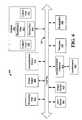
- FIG. 4is a block diagram depicting an exemplary computing system of the wearable health monitoring device as depicted in FIG. 1
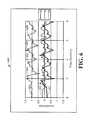
- FIG. 5is a graph depicting a plurality of outputs of a 3-axis accelerometer depicting a human standing, walking, and falling.
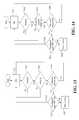
- FIG. 7is a block diagram depicting exemplary architecture of the control logic of the health monitoring device depicted in FIG. 4 .
- FIG. 8is a block diagram depicting another exemplary architecture of the control logic of the health monitoring device depicted in FIG. 4 .
- FIG. 9is a bar chart depicting exemplary activity-induced energy expenditure.
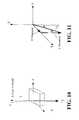
- FIG. 10is a diagram depicting a 3-axis coordinate and a gravity vector.
- FIG. 11is a diagram depicting the resultant effect of the gravity vector on the 3-axis coordinate depicted in FIG. 10 .
- FIG. 12is a flowchart depicting exemplary architecture and functionality of the control logic depicted in FIG. 4 for determining whether a user of the health monitoring device depicted in FIG. 1 has taken a step
- FIG. 13is a flowchart depicting exemplary architecture and functionality of the control logic depicted in FIG. 4 for determining whether a user of the health monitoring device depicted in FIG. 1 has fallen.
- FIG. 14is a flowchart depicting another exemplary architecture and functionality of the control logic depicted in FIG. 4 for determining whether a user of the health monitoring device depicted in FIG. 1 has fallen.
- Ambulatory health monitoringcan have many advantages including frequent monitoring of health metrics, monitoring in the user's natural setting, early detection of abnormal physiological levels, and building a history of user's health information.
- measures of an individual's activity(Activity-induced Energy Expenditure), number of daily steps, and their sleep/wake patterns are also generally deemed useful measures of health information.
- Certain high need individualssuch as seniors living alone or individuals with chronic illnesses, may realize the greatest benefit of ambulatory monitoring.
- Self-test devicessuch as thermometers, manual measurement of heart rate, and pedometers can be employed to generate data related to ambulatory monitoring.
- a comprehensive health monitoring device equipped with the ability to continuously monitor and assess activitycould provide greater benefit to individuals wearing the device.
- the present disclosureprovides a wearable device which includes either a microcontroller or digital signal processor (DSP), a battery, a battery management and power distribution system, and at least one physiological sensor from the following list: electrodes for monitoring cardiac and other muscular activity; oxygen saturation sensors (SpO 2 ); galvanic skin response (GSR) sensors; multi-axis accelerometer for monitoring motion; angular rate sensor (or gyroscope); temperature sensor.
- DSPdigital signal processor
- a batterya battery management and power distribution system
- at least one physiological sensorfrom the following list: electrodes for monitoring cardiac and other muscular activity; oxygen saturation sensors (SpO 2 ); galvanic skin response (GSR) sensors; multi-axis accelerometer for monitoring motion; angular rate sensor (or gyroscope); temperature sensor.
- DSPdigital signal processor
- FIG. 1depicts an exemplary perspective view of a wearable health monitoring device 100 in accordance with an embodiment of the present disclosure.
- the wearable health monitoring device 100comprises a controller housing 103 and a strap 101 , e.g., an elastic strap.
- the controller housing 103attaches to the strap 101 with two or more electrode snaps 104 .
- the snaps 104serve a dual purpose to both attach and secure as well as provide electrical connection to the elastic strap's electrodes, which is described further herein with reference to FIG. 2 .
- the wearable health monitoring device 100further comprises a connector 105 for fastening and/or tightening the elastic strap 101 around a user's torso.
- controller housing 103may be comprised of any type of suitable material known in the art or future-developed, including plastic.
- the controller housing 103is comprised of a water resistant type of material.
- the wearable health monitoring device 100can be used during bathing or swimming.
- the wearable health monitoring device 100is perpetually in an activated state, i.e., powered on.
- the controller housing 103further comprises an actuator 102 for signaling a remote device (not shown).
- the actuator 102may be, for example, a button or a switch that when actuated generates a message which is wirelessly transmitted to the remote device, which is described further with reference to FIG. 3 .
- FIG. 2depicts an exemplary perspective view of a back side of the wearable health monitoring device 100 .
- the wearable health monitoring device 100comprises one or more dry fabric electrodes 200 embedded within the strap 101 .
- the electrodes 200are made of conductive polymer yarn and formed in a mesh.
- Each of the electrode snaps 104comprise on one side a snap female receptacle 205 , which mates with the controller housing snap male connector 206 . Therefore, the electrode snaps 104 are removeably attached to the controller hosing 103 by inserting the male connector 206 into the female connector 205 .
- Each dry fabric electrode 200 embedded in the strap 101is connected to the female connector 205 .
- the female connector 205is riveted through the mesh dry fabric electrode 200 thereby establishing an electrical connection between the electrode 200 and the female connector 205 .
- the male connector 206is conductively connected to a printed circuit board (PCB) (not shown) within the controller housing 103 .
- PCBprinted circuit board
- the wearable health monitoring device 100further comprises one or more metal contacts 207 .
- the metal contact 207is conductively coupled to a thermistor (not shown) on the PCB, which detects temperature.
- the metal contact 207further serves as a third lead of an electrocardiogram (ECG) signal.
- ECGelectrocardiogram
- the first and second electrodes 200serves as the differential leads of the ECG signal and are biopotential electrodes for measuring biopotentials of the body and generating electrocardiogram (ECG) measurements.
- ECGelectrocardiogram
- the electrodes 200can be placed so they are across a user's heart, and a differential measurement is used to obtain and record ECG data.
- the metal contact 207serves as the third lead when obtaining the ECG data.
- the electrodes 200may be used to detect a heartbeat of the user.
- heartbeat detectioncan be extracted in any manner known or future-developed.
- the electrodes 200detect a user's heartbeat through R-peak detection. This can be in the form of hardware or software detection of the maximum peak waveform contained in the deflections in the tracing of the electrocardiogram (ECG), comprising the “Q,” “R,” and “S” waves, also referred to as the QRS Complex.
- ECGelectrocardiogram
- the “Q,” “R,” and “S” wavesrepresent the respective ventricular activity of a Heart (not shown).
- the wearable health monitoring device 100via the electrodes 200 , measures the elapsed time between each R-peak (hereinafter referred to as an “R-peak interval”), and the instantaneous heart rate may be calculated as the inverse of the measured R-peak interval.
- the ECG datacan be extracted from any various number of electrode configurations ranging from two to twelve electrodes.
- the use of three electrodes (two dry fabric 200 and one metal 207 ) in FIG. 2is for exemplary purposes only, and other numbers of electrodes in other embodiments are possible.
- the electrodes 200may be used to obtain respiration rate.
- the ECG signalis used to extract respiration rate using a low frequency response filter (not shown).
- the wearable health monitor device 100performs such extraction by employing a low pass filter (LPF) (not shown) and determining the period of a signal (not shown) transmitted by the LPF.
- LPFlow pass filter
- the low pass filtercan be implemented in hardware, in DSP firmware, or microcontroller software.
- the wearable health monitoring device 100analyzes a magnitude of the QRS complex in the time domain and extracts a magnitude of the R-peak as a function of time using the electrodes 200 . The wearable health monitoring device 100 then analyzes the derived signal to determine the period (detecting relative maximum), indicative of a respiration rate.
- the wearable health monitoring device 100extracts measures of Heart Rate Variability (HRV).
- HRVHeart Rate Variability
- time domainstandard deviation
- frequency domain representatione.g., time domain (standard deviation)
- the wearable health monitoring device 100calculates the HRV in system or during post-analysis by analyzing a time series of heartbeats.
- FIG. 3depicts a system 300 in accordance with an embodiment of the present disclosure.
- the system 300comprises the wearable health monitoring device 100 , as depicted in FIGS. 1 and 2 , which is being worn by a user 301 .
- the system 300comprises at least one data-receiving unit 302 .
- the wearable health monitoring device 100communicates with the data-receiving unit 302 over a local network 321 , e.g., Zigbee.
- the data-receiving unit 302 and/or the monitoring device 100communicates with a central monitoring device 305 via a network 303 .
- the network 303may be any type of network known in the art of future-developed.
- the network 303may be, for example, broadband over power lines (BPL), optical fiber, Ethernet, a local area network (LAN), a wireless local area network (WLAN), or a wide area network (WAN).
- BPLbroadband over power lines
- LANlocal area network
- WLANwireless local area network
- WANwide area network
- the data-receiving unit 302 , the wearable health monitor 101 , and the central monitoring device 305comprise hardware and/or software (not shown) known in the art or future-developed for communicating over the networks 321 and 303 , which is described further herein.
- the user 301wears the wearable health monitoring device 100 .
- one exemplary location of the wearable health monitoring device 100is above the user's waist 308 so that a static response (due to gravity) is in relation to an upper torso region 305 of the user 301 .
- mounting the wearable health monitoring device 100is accomplished by wrapping the elastic strap 101 ( FIG. 1 ) around the user's chest 307 and connecting the elastic strap 101 via the connector 105 ( FIG. 1 ). Note that the health monitoring device 100 is worn around the chest 307 next to the skin, i.e., under the clothes of the user 301 .
- the wearable health monitoring device 100transmits physiological data to the data-receiving unit 302 .
- the device 100may transmit the physiological data to the data-receiving unit 302 upon request, continuously, or automatically at predetermined intervals.
- the data-receiving unit 302receives the physiological data and generates historical health data related to the user 301 or detect particular events based upon the physiological data received from the monitoring device 100 .
- the system 300further comprises the central monitoring device 305 .
- the central monitoring device 305may be substantially similar to the data-receiving unit 302 .
- the wearable monitoring device 100provides real-time physiological data related to the user 300 to a device monitor 304 , e.g., an individual, via the central monitoring device 305 .
- the central monitoring device 305displays data indicative of the event on a graphical user interface (GUI) (not shown). Based upon the displayed data, the device monitor 304 can take an action based upon the physiological data indicative of the event, e.g., call emergency personnel for the user 301 .
- GUIgraphical user interface
- the device monitor 304is depicted graphically as a person.
- the central monitoring device 305may automatically, upon receipt of the physiological data, electronically notify emergency personnel.
- the wearable health monitoring device 100extracts features specifically related to the user's motion, respiration, cardiac activity, temperature, and the like.
- an accelerometerdescribed further with reference to FIG. 4 , is used, which extracts features based upon a 3-axis coordinate system depicted in FIG. 3 .
- Exemplary processes and methods for extracting such featuresare described further herein, and include processes for estimating the user's level of activity or approximating caloric expenditure, categorizing user activity, detecting a fall, step detection, or orientation detection, for example.
- FIG. 4is a block diagram depicting an exemplary controller 400 of the present disclosure that is contained in the controller housing 103 ( FIG. 1 ) of the wearable health monitor 100 ( FIG. 1 ).
- the exemplary controller 400comprises a processor 403 , an output device 405 , an input device 404 , a communication device 410 , and a power supply 409 .
- the exemplary controller 400comprises a thermistor 407 and one or more bioamplifiers 408 . Each of these components communicates over local interface 407 , which can include one or more buses.
- the controller 400comprises an accelerometer 406 and an analog-to-digital converter (ADC) 413 .
- ADCanalog-to-digital converter
- Controller 400further comprises control logic 402 , physiological data 411 , motion data 414 , and control data 412 .
- Control logic 402can be software, hardware, or a combination thereof. In the exemplary controller 400 shown in FIG. 4 , control logic 402 , is shown as software stored in memory 401 .
- Memory 401may be of any type of memory known in the art, including, but not limited to random access memory (RAM), read-only memory (ROM), flash memory, and the like.
- control logic 402physiological data 411 , motion data 414 , and control data 412 are shown in FIG. 4 as software stored in memory 401 .
- control logic 402physiological data 411 , motion data 414 , and control data 412 can be stored and transported on any computer-readable medium for use by or in connection with an instruction execution system, apparatus, or device, such as a computer-based system, processor-containing system, or other system that can fetch the instructions from the instruction execution system, apparatus, or device and execute the instructions.
- a “computer-readable medium”can be any means that can contain, store, communicate, propagate, or transport the program for use by or in connection with the instruction execution system, apparatus, or device.
- the computer readable mediumcan be, for example but not limited to, an electronic, magnetic, optical, electromagnetic, infrared, or semiconductor system, apparatus, device, or propagation medium
- Processor 403may be a digital signal processor (DSP) or other type of circuitry configured to run the control logic 402 by processing and executing the instructions of the control logic 402 .
- DSPdigital signal processor
- the communication device 410may be, for example, a low-powered radio device, e.g., a radio semiconductor, radio frequency antenna (RF antenna); a wired communication device such a RS232, USB, or Ethernet; or other wireless communication device, such as a magnetic communications scheme or infrared scheme; or any type of communication device, which communicatively couples the controller 400 to the data-receiving device 302 ( FIG. 3 ) and/or the central monitoring device 305 .
- a low-powered radio devicee.g., a radio semiconductor, radio frequency antenna (RF antenna); a wired communication device such a RS232, USB, or Ethernet; or other wireless communication device, such as a magnetic communications scheme or infrared scheme; or any type of communication device, which communicatively couples the controller 400 to the data-receiving device 302 ( FIG. 3 ) and/or the central monitoring device 305 .
- a low-powered radio devicee.g., a radio semiconductor, radio frequency antenna (RF antenna
- physiological data 411 and motion data 414can be relayed in a real-time manner, a periodic manner, an “as they occur” fashion, or some combination of the three. For example, a serious condition such as an individual falling could be relayed to the central monitoring device 305 ( FIG. 3 ).
- the bioamplifier 408is a device that interfaces with the electrodes 200 .
- the bioamplifier 408gathers, amplifies, filters and conditions the signal integrity of human physiological activity for use by the control logic 402 .
- the signals (not shown) collected by the bioamplifier 408 from the electrodes 200relate to the nervous system of the user 301 ( FIG. 3 ).
- the signals collectedare stored as the physiological data 411 , and are used by the control logic 402 .
- the output device 405is a device for communicating information to the user 301 ( FIG. 3 ).
- the output device 405may be, for example, an LED that indicates that power is on.
- the output device 405may be a speaker that emits a sound upon the occurrence of a particular event, e.g., when the battery needs to be charged or upon activation.
- Physiological data 411includes data obtained from the one or more sensors, e.g., the thermistor 407 or the bioamplifier 408 .
- the physiological data 411comprises data indicative of physiological aspects of the user 301 ( FIG. 3 ).
- Examples of physiological data 411include data indicative of ECG readings, heartbeat readings, temperature readings, or the like.
- Motion data 414includes data obtained from the accelerometer 406 .
- the motion data 414comprises data indicative of movement of the user.
- the motion data 414includes data indicative of the user 301 in an X-direction, Y-direction, and the Z-direction.
- the input device 404enables the user 301 to enter data into the controller 400 .
- the input device 404is the actuator 102 ( FIG. 1 ).
- the controller 400recognizes this as a user button which generates a message which is sent over the network 303 and is detected by the remote device monitor 304 .
- Other input devicesmay be used in other embodiments.
- the input device 404may be a keyboard or a touch screen for performing particular operations on the controller 400 .
- the input device 404is a microphone (not shown), and an exemplary output device 405 is a speaker (not shown), as described hereinabove.
- the speaker and the microphoneenable the user 301 to be in communication with the device monitor 304 where the device monitor 304 is a person.
- the wearable health monitoring device 100detects an event, such as, for example, a fall or a negative change in the user's physiological condition based upon received physiological data 411 .
- the central monitoring device 305receives the physiological data 411 and alerts the device monitor 304 to the particular concern.
- the device monitor 304then contacts the user 301 over the network 303 via the microphone/speaker input/output arrangement.
- the thermistor 407is conductively coupled to the metal contact 207 ( FIG. 2 ) as described hereinabove.
- the thermistor 407is a device that measures a skin temperature of the user 301 where the thermistor 407 is in contact with the metal contact 207 , which is in contact with the skin of the user 301 .
- the thermistor 407is a thermocouple (not shown) integrated with the housing 103 , and the thermocouple protrudes from the backside of the housing 103 . Placing it on the backside of the control housing 103 places the thermocouple in direct contact with the user's skin. In such an embodiment, leads (not shown) from the thermocouple are attached to the controller 400 .
- the metal contact 207( FIG. 2 ) is mounted inside the controller housing 103 and is mounted to the thermistor 407 of the controller 400 .
- the thermistor 407is mounted so that either the thermistor 407 is in direct contact with the thermally conductive metal contact 207 integrated with the controller housing 103 for detecting physiological data 411 indicative of skin temperature or it is positioned so that an intermediary thermally conductive material (not shown) can connect to the thermistor 407 and the contact 207 .
- the metal contact 207may be comprised of materials, such as, copper, aluminum, stainless steel, thermally conductive polymers or plastics.
- the metal contact 207is made of a combination of materials such as a thermally conductive gap filler connecting or thermal grease which connects the thermal contact 207 to the thermistor 407 .
- the accelerometer 406is a 3-axis accelerometer for monitoring motion.
- the accelerometer 406may be a direct current (“DC”) response or a non-DC response accelerometer.
- the accelerometer 406is a microelectromechanical (“MEMS”) piezoresistive technology sensor (not shown), however other types of accelerometers known in the art or future-developed may be used in other embodiments of the controller 400 .
- MEMSmicroelectromechanical
- the accelerometer 406measures acceleration due to gravity and physical movement and transmits the raw analog signals to the ADC 413 .
- the ADC 413translates the received analog into digital data indicative of the received analog signals (not shown).
- the ADC 413provides the digital data indicative of the analog signals to the control logic 402 , which can store the digital data as motion data 414 .
- the control logic 402then calculates and stores additional motion data 414 including activity-induced energy expenditure (AEE) and/or orientation, based upon the motion data 414 .
- the control logic 402can use the motion data 414 to detect a fall, detect steps made by the user 301 , and categorize activity performed by the user 301 .
- AEEactivity-induced energy expenditure
- the accelerometer 406may be a single (or dual) axis accelerometer arranged to create a three-axis orthogonal coordinate system, as depicted in FIG. 3 as X, Y, and Z axes.
- FIG. 3illustrates one possible axis orientation for a wearable health monitoring device including a 3-axis accelerometer sensor.
- the control logic 402reacts quickly to changes in real-time and also reduces the data stream, thereby maximizing the storage capabilities of memory 401 .
- Reducing the data streammay refer to techniques for averaging the data, or inspecting the real-time stream for certain feature extraction.
- One such techniqueis described in U.S. patent application Ser. No. 11/972,335 entitled Wireless Sensor Network Context Data Delivery System and Method.
- FIG. 5is a graph 500 that illustrates digitized signals 501 - 503 obtained from an accelerometer 406 ( FIG. 4 ) wherein the accelerometer 406 is a 3-axis accelerometer. As described herein, the accelerometer 406 provides the raw analog signals to the ADC 413 before the signals 501 - 503 are provided to the control logic 402 .
- the accelerometer 406 and ADC 413 from which the data plotted in the graph 500 is obtainedis housed in the controller housing 103 ( FIG. 1 ) by the user 301 ( FIG. 3 ) in the upper torso position depicted in FIG. 3 .
- three axesi.e., X-axis, Y-axis, and Z-axis, denote the three dimensions of movement possible for the user 301 and for which the accelerometer 406 obtains signals.
- the graph 500comprises an “Acceleration” axis in “g” and a corresponding “Time” axis in seconds. Note that the symbol “g” refers to the gravitational pull of Earth at sea level.
- the graph 500comprises the signal 501 , the signal 502 , and the signal 503 , which correspond to the X-axis, the Y-axis, and the Z-axis of FIG. 3 .
- the signal 501corresponds to movement of the user 301 in an X-direction
- the signal 502corresponds to movement of the user 301 in a Y-direction
- the signal 503corresponds to movement of the user 301 in a Z-direction.
- Each signalis indicated in the legend as Ax, Ay, and Az, respectively.
- the change in orientationis indicated by the change in location on the acceleration axis of the signals 501 - 503 following the fall. Note that this orientation is calculated as a function of the static response due to gravity and how it acts on each axis.
- the signal 502 in the Y-directionremains very near its original value, and the signal 503 in the Z-direction changes from approximately 1 g prior to the fall to slightly less than 0 g after the fall.
- the change in the DC components of the acceleration valuesindicates a change in orientation.
- the user 301may have been in an upright position; however, after the fall, the user may now be in a supine position.
- the notations of the signals 501 - 503remain the same, i.e., signal 501 is indicative of movement in the X-direction, signal 502 is indicative of movement in the Y-direction, and signal 503 is indicative of movement in the Z-direction.
- Each signal 501 - 503comprises peaks; however, for simplicity and brevity only those peaks in the Z-direction are identified in FIG. 6 .
- FIG. 7depicts exemplary architecture and functionality of the control logic 402 ( FIG. 4 ) in accordance with an embodiment of the present disclosure.
- the control logic 402can be software, hardware, or any combination thereof.
- the accelerometer 406transmits raw analog signals (not shown) detected by a respective sensor (not shown) of the accelerometer 406 corresponding to each of the X, Y, and Z directions, to the ADC 413 ( FIG. 4 ).
- the ADC 413translates the analog signals received into digital signals Ax, Ay, and Az 503 , and provides the signals to the control logic 402 .
- each of these signals 501 - 503comprises an alternating current (AC) component and direct current (DC) component.
- the ADC 413then provides the digitized signals 501 - 503 to the control logic 402 .
- FIG. 7depicts an exemplary embodiment of control logic 402 .
- the control logic 402comprises three separate tiers 710 - 712 that operate to manipulate each of the three separate input signals Ax 501 , Ay 402 , and Az 503 provided by the ADC 413 ( FIG. 4 ) into data indicative of an AC component, i.e., AC(Ax′), AC(Ay′), and AC(Az′), and data indicative of a DC component, i.e., DC(Ax′), DC(Ay′), and DC(Az′).
- AC componenti.e., AC(Ax′), AC(Ay′), and AC(Az′
- DC componenti.e., DC(Ax′), DC(Ay′), and DC(Az′
- the circuits 710 , 711 , and 712comprise low pass filters 701 .
- the low pass filters 701remove high-frequency noise (not shown) of the input signal Ax 510 , and Ax 503 and transmits as output the direct current (DC) portion of each of the signals DC(Ax′), DC(Ay′), and DC(Az′).
- the signals Ax, Ay, and Azare transmitted to summation circuits 703 .
- the summation circuits 703further receive the output signals DC(Ax′), DC(Ay′), and DC(Az′) from the low pass filter 701 .
- the summation circuit 703subtract the output signals DC(Ax′), DC(Ay′), and DC(Ax′) from the signals Ax, Ay, and Az to obtain the AC components AC(Ax′), AC(Ay′), and AC(Az′) of the signals Ax, Ay, and Az, respectively.
- a post filter median or low pass filteris applied to further smooth the signals AC(Ax′), AC(Ay′), and AC(Az′).
- the motion data 414( FIG. 4 ) indicative of the input signals Ax, Ay, and Az obtained from the accelerometer 406 are represented as a stream of discrete samples occurring in real-time, as defined by an application sampling frequency, the graphs of which are illustrated in FIGS. 5 and 6 .
- FIG. 8depicts another exemplary architecture and functionality of the control logic 402 ( FIG. 4 ) in accordance with an embodiment of the present disclosure.
- the control logic 402can be software, hardware, or any combination thereof.
- the ADC 413translates the analog signals received into digital signals Ax 501 , Ay 502 , and Az 503 , and provides the signals to the control logic 402 .
- each of these signals 501 - 503comprises an alternating current (AC) component and direct current (DC) component.
- the ADC 413then provides the digitized signals 501 - 503 to the control logic 402 .
- the control logic 402 depicted in FIG. 8comprises three separate tiers 2010 - 2012 that operate to manipulate each of the three separate input signals Ax 501 , Ay 502 , and Az 503 provided by the ADC 413 ( FIG. 4 ) into data indicative of an AC component, i.e., AC(AX′), AC(Ay′), and AC(Az′), and data indicative of a DC component, i.e., DC(Ax′), DC(Ay′), and DC(Az′).
- the circuit 2010comprises a median or low pass filter 2002 with a very low cutoff frequency. In an exemplary embodiment, this is set at 0.1 Hz.
- the filter 2002is used to remove high-frequency noise of from the signal Ax to obtain resultant signal Ax′.
- the signal AX′is then transmitted through a high pass filter 2004 to generate the alternating current portion AC(Ax′) only of the Ax′ signal.
- the signal Ax′is transmitted to a summation circuit 2003 , and the summation circuit 2003 also receives the signal AC(Ax′) from the high pass filter 2004 .
- the summation circuit 2004subtracts AC(Ax′) from the input signal Ax′to obtain the DC component DC(Ax′) of the signal Ax.
- a median filtercan be applied to post filter and further smooth the AC(Ax′) signal.
- one embodimentemploys DC extraction using a low pass filter to achieve the DC component and subtracting the DC component from the input signal to obtain the AC signal component, as is shown in FIG. 7
- another embodimentemploys AC extraction using a high pass filter to obtain the AC component and subtracting the AC component from the input signal to obtain the DC signal component, as shown in FIG. 8 .
- the motion data 414comprises data indicative of a plurality of AC signals AC(Ax′), AC(A y ′), and AC(A z ′) and a plurality of DC signals DC signals DC(Ax′), DC(A y ′), and DC(A z ′).
- the control logic 402receives the plurality of generated signals AC(A x ′), AC(A y ′), and AC(A z ′) from the motion data 414 or from the ADC 413 , as described hereinabove.
- the control logic 402upon receipt of the signals AC(A x ′), AC(A y ′), and AC(A z ′), calculates AEE based upon the following formula:
- a ⁇ ⁇ E ⁇ ⁇ E⁇ t t + T ⁇ AC ⁇ ( A x ′ ) 2 + AC ⁇ ( A y ′ ) 2 + AC ⁇ ( A z ′ ) 2 , ⁇ A ⁇ .1
- Tis the integration period.
- an integration period in formula A.1is application dependent.
- the calculated AEEis useful for interpreting the magnitude of a response.
- the control logic 402implements the integral from discrete samples of the signals AC(A x ′), AC(A y ′), and AC(A z ′) stored as motion data 414 by calculating a cumulative sum of the samples.
- the control logic 402calculates the square root of AC(A x ′) 2 +AC(A y ′) 2 +AC(A z ′) 2 The sum of these values represents an AEE for a given time, T.
- a temporary variableis first initialized to zero (every T/f s operations) and a cumulative sum is generated.
- the AEE resultis available every T/f s operations.
- FIG. 9shows AEE for a one second integration periods as calculated over an entire ten second time interval.
- control logiccalculates an orientation of the user 301 ( FIG. 3 ) based upon the DC signals DC(Ax′), DC(Ay′), and DC(Az′) stored as motion data 414 .
- orientation of the user 301refers to whether the individual's upper torso region is horizontal or vertical.
- the control logic 402receives and analyzes the signals DC(A x ′), DC(A y ′) and DC(A z ′) to determine an angle ⁇ between the z-dimension axis and the effect of gravity represented by the vector “1 g.”
- FIG. 11depicts the static effects of gravity and how the vector “1 g” is measured on each axis X, Y, and Z.
- FIG. 13shows the effect of gravity on each axis prior to a fall, where the user was in the vertical orientation and just after a fall, where the user was in a horizontal orientation.
- the present disclosurediscloses a method for calculating this angle ⁇ as a function of DC(A x ′), DC(A y ′), and DC(A z ′).
- One embodiment of the present disclosurecategorizes horizontal and vertical orientation in terms of ⁇ as follows:
- Yet another embodimentsimplifies the calculation by recognizing that the angle ⁇ is a function only of DC(A z ′) and the magnitude of the vector formed by gravity. Because the magnitude of the measured vector should be very near 1 g, it can be approximated—thus avoiding the inverse cosine calculation—by forming a look-up table or simple comparison based on DC(A z ′).
- the following tableillustrates one possible method:
- DC(z′) OrientationDC(z′) > k h1 or DC(z′) ⁇ k h2 Vertical k h1 > DC(z′) > k h2 Horizontal Where cos(0°) > k h1 > cos(90°) and cos(90°) > k h2 > cos(180°)
- Yet another embodimentfirst compensates for offset from the initial device placement as described within “Wireless Sensor Network System And Method For Using The Same”, U.S. Provisional Patent Application No. 60/884,352, filed Jan. 10, 2007. Using the methods contained within combined with those disclosed in this present disclosure, it is possible to extract orientation even when the device is erroneously worn—such as if it were placed upside down.
- control logic 402further detects steps performed by the user 300 ( FIG. 3 ) as described with reference to FIG. 12 . In order to determine whether a step has occurred by the user 300 , the control logic continuously monitors the signals AC(A x ′), AC(A y ′), and AC(A z ′).
- FIG. 12is a flowchart depicting exemplary architecture and functionality of the control logic 402 for detecting a step of a user 301 ( FIG. 3 ).
- the control logic 402initially remains idle, as indicated by step 1201 until a minimum amount of activity energy estimation (AEE) has met or exceeded a threshold “K,” as indicated in step l 202 .
- AEEactivity energy estimation
- a stepis determined by detecting a relative minimum followed by a relative minimum on the post filtered AC(Az′) signal within a given time window and further qualifying by assuring the user is not in a supine position (using intermediate signal orientation).
- control logic 402determines whether there has been a relative minimum of the post-filtered AC(Az′) as indicated in step 1203 .
- the control logic 402detects the relative minimum from the signal AC(Az′) by comparing each digital sample in AC(A z ′) to one or more previous and subsequent samples in AC(Az′). Thus, a relative minimum is detected when the current discrete sample is less than the previous sample and the following sample is greater than the current sample.
- step 1203the control logic 402 determines whether there is a relative minimum from signal AC(A z ′) in step 1204 . Similar to the discussion with reference to step 1203 , the control logic 402 detects the relative maximum from the signal AC(Az′) by comparing each digital sample in AC(A z ′) to one or more previous and subsequent samples in AC(Az′). Thus, a relative maximum is detected when the current discrete sample is greater than the previous sample and the following sample is less than the current sample.
- control logic 402determines if the user is in a non-horizontal orientation, as indicated in step 1205 .
- control logic 402stores motion data 414 indicative of a step having been performed at the particular time, as indicated in step 1206 . If the precise time occurrence of the step is of importance to the application, this can be defined by the user and stored as control data 412 .
- the magnitude of the relative maximum and relative minimumcan be used to further qualify the step detection.
- the phase relationship between other axescould be examined to further qualify the step.
- the control logic 402monitors the number of steps taken by the user 301 over time.
- the control logic 402can start a counter and each time a step is detected and stored in step 1206 , the counter can be incremented. After a given time interval, for example sixty seconds, the control logic 402 can stop the counter and store motion data 414 ( FIG. 4 ) in memory 401 ( FIG. 4 ) indicating the number of steps taken during the time interval. The control logic 402 can transmit this motion data 414 to the central monitoring device 305 for storage, display, or further analysis.
- FIG. 13is a flowchart illustrating exemplary architecture and functionality of the control logic 402 for detecting a fall of the user 301 in accordance with an embodiment of the present disclosure.
- control logic 402remains in an idle state, as indicated in step 1301 .
- the control logic 402determines if the user 301 is in a vertical position, as indicated in step 1302 . If the user is in a vertical position, then the control logic 402 compares a calculated AEE with a predefined threshold “k,” as indicated in step 1303 .
- the threshold kis set sufficiently high so as not to be exceeded by normal activity levels.
- AEEis sampled more often and AEE threshold exceeding can be determining if n out of m consecutive AEE samples are above k. In yet another embodiment, this can be further qualified to ensure that at least one of the m sampled AEE values is above a higher threshold j, where j>k.
- the control logic 402determines whether there is a change in orientation from vertical to horizontal, as indicated in step 1304 . If a continued horizontal state with relatively low activity (AEE ⁇ l and l ⁇ k) for some period of time, as indicated in step 1305 , the control logic 402 takes action, in step 1306 , e.g., stores data indicative of a fall or alerts the central monitoring device 305 .
- AEE ⁇ l and l ⁇ krelatively low activity
- control logic 402If while in steps 1301 - 1304 , an event does not transpire in a reasonable elapsed time, the control logic 402 returns to the idle (appropriate orientation) state in step 1301 .
- FIG. 14depicts additional architecture and functionality of the control logic 402 for determining a fall.
- the control logic 402remains idle, until the control logic 402 determines whether the user 301 ( FIG. 3 ) is vertical, in step 1402 .
- step 1404the control logic 402 determines whether there is a change in orientation from vertical to horizontal. If the control logic 402 determines that the user 301 is in a continued horizontal state with relatively low activity (AEE ⁇ l) for some period of time, as indicated in step 1405 , the control logic 402 takes action in step 1406 . In this regard, the control logic 402 may store data indicative of a fall or the control logic 402 may transmit an alert to central monitoring device 305 ( FIG. 3 ).
- the control logic 402categorizes activity of the user 301 based upon data received.
- the present disclosurediscloses a method for categorizing user activity. Using a microcontroller or DSP and having employed the signal processing architecture disclosed in present disclosure, derived signals Orientation, AEE, and Steps are of interest. The method provides for discerning four categories of activity: sleeping, sitting or standing, walking, and running.
- the present disclosurealso discloses monitoring of other physiological signals if available. For example, while the user is horizontal, it is imperative to ensure that the individual is okay. Heart rate, if available, provides a good indication of this and can be used to differentiate sleeping and other life threatening situations.
- the above tabledoes not accommodate history and in the case of a user having suffered a fall, software should keep state of this and use it to qualify the categorized activity. That is, a user is only sleeping if having not suffered a fall and all vitals are still okay.
- all extracted featuresshould be qualified with whether the device is being worn. A method for determining if the device is being worn is disclosed within the present disclosure.
- the present disclosurediscloses a method for discerning periods of sleep and wake. For present purposes, sleep and wake are more simply categorized by sleep and not sleep. Based on the methods for categorizing activity which has already been disclosed, it becomes possible to recognize periods of rest and consequently periods of non-rest. For most purposes, rest and sleep are synonymous.
- One embodimentmakes use one or more of heart rate, respiration, and skin temperature sensors when available.
- heart rate, respiration rate, and skin temperaturedecline while sleeping.
- the present disclosurediscloses a method for discerning rest from sleep by recording these parameters at onset of rest. If the parameters fall below a certain threshold (relative to recorded parameter at onset of rest), then the activity can be categorized as sleep.
- the control logic 402detects whether the device 100 has been removed. Notably, when dry electrodes 200 ( FIG. 2 ) and a metal electrode 207 ( FIG. 2 ) are used, heart beat detection stops and the detected temperature begins to drop quickly if the device 100 is removed from the user 300 .
- device removalcan be defined as no heart beat and temperature below a threshold. At the beginning of onset of absence of heart beats, the rate of change of temperature must also be used as a determination.
- control logic 402uses the electrodes 200 and applies a small potential to the body. By measuring the induced current, it can be determined if the electrodes 200 are in contact with the user's body. If current is induced, the electrodes 200 are in contact with a conductive body and can be determined to be being worn. This can be accomplished by providing a voltage source with a known impedance (a voltage follower amplifier in series with a resistor) and measuring the voltage on the output of the voltage source. If the measured voltage is at or near the source voltage, the loop is open and not in contact with skin. If the measured voltage is significantly lower than the source voltage, then it can be determined that the loop is closed and current is flowing thus causing a voltage drop in the resistive output of the voltage source.
- a voltage sourcewith a known impedance (a voltage follower amplifier in series with a resistor) and measuring the voltage on the output of the voltage source. If the measured voltage is at or near the source voltage, the loop is open and not in contact with skin. If the measured voltage is significantly lower than the
- the electrodesare in contact with a conductive material (presumably human skin). If deemed necessary, this could be further qualified for known resistive properties for humans so as to differentiate from a scenario where the device was laid on another non-human conductive surface.
- the present disclosurecomprises a wearable health monitoring device and methods for motion-based feature extraction. While particular embodiments of the disclosure have been described, it will be understood, however, that the disclosure is not limited thereto, since modifications may be made by those skilled in the art, particularly in light of the foregoing teachings. It is, therefore, contemplated by the appended claims to cover any such modifications that incorporate those features or those improvements that embody the spirit and scope of the present disclosure.
Landscapes
- Health & Medical Sciences (AREA)
- Life Sciences & Earth Sciences (AREA)
- Engineering & Computer Science (AREA)
- Medical Informatics (AREA)
- Physics & Mathematics (AREA)
- Veterinary Medicine (AREA)
- Biophysics (AREA)
- Pathology (AREA)
- Public Health (AREA)
- Biomedical Technology (AREA)
- Heart & Thoracic Surgery (AREA)
- General Health & Medical Sciences (AREA)
- Molecular Biology (AREA)
- Surgery (AREA)
- Animal Behavior & Ethology (AREA)
- Oral & Maxillofacial Surgery (AREA)
- Physiology (AREA)
- Dentistry (AREA)
- Measuring And Recording Apparatus For Diagnosis (AREA)
Abstract
Description
where T is the integration period.
u·v=|u∥v| cos φ
u=(0,0,1)
v=DC(x′),DC(y′),DC(z′)
| Angle Φ | Orientation | ||
| Φ < β or Φ > γ | Vertical | ||
| B < Φ < γ | Horizontal | ||
| Where 0° < β < 90° and 90° < γ < 180° | |||
| DC(z′) | Orientation | ||
| DC(z′) > kh1or DC(z′) < kh2 | Vertical | ||
| kh1> DC(z′) > kh2 | Horizontal | ||
| Where cos(0°) > kh1> cos(90°) and cos(90°) > kh2> cos(180°) | |||
| Orientation | AEE | Steps Detected | Category of Activity |
| Horizontal | AEE < k | — | Resting1 |
| Vertical | — | No | Standing or Sitting |
| Vertical | l < AEE < m | Yes | Walking |
| Vertical | AEE > m | Yes | Vigorous Walking or |
| Running | |||
| Where k << l << m | |||
Claims (13)
Priority Applications (1)
| Application Number | Priority Date | Filing Date | Title |
|---|---|---|---|
| US12/192,830US9295412B2 (en) | 2007-08-15 | 2008-08-15 | Wearable health monitoring device and methods for step detection |
Applications Claiming Priority (2)
| Application Number | Priority Date | Filing Date | Title |
|---|---|---|---|
| US95601407P | 2007-08-15 | 2007-08-15 | |
| US12/192,830US9295412B2 (en) | 2007-08-15 | 2008-08-15 | Wearable health monitoring device and methods for step detection |
Publications (2)
| Publication Number | Publication Date |
|---|---|
| US20090069724A1 US20090069724A1 (en) | 2009-03-12 |
| US9295412B2true US9295412B2 (en) | 2016-03-29 |
Family
ID=40363532
Family Applications (2)
| Application Number | Title | Priority Date | Filing Date |
|---|---|---|---|
| US12/192,830Active2029-04-10US9295412B2 (en) | 2007-08-15 | 2008-08-15 | Wearable health monitoring device and methods for step detection |
| US12/192,855Active2029-08-21US9179864B2 (en) | 2007-08-15 | 2008-08-15 | Wearable health monitoring device and methods for fall detection |
Family Applications After (1)
| Application Number | Title | Priority Date | Filing Date |
|---|---|---|---|
| US12/192,855Active2029-08-21US9179864B2 (en) | 2007-08-15 | 2008-08-15 | Wearable health monitoring device and methods for fall detection |
Country Status (1)
| Country | Link |
|---|---|
| US (2) | US9295412B2 (en) |
Cited By (3)
| Publication number | Priority date | Publication date | Assignee | Title |
|---|---|---|---|---|
| US11024142B2 (en) | 2017-07-27 | 2021-06-01 | NXT-ID, Inc. | Event detector for issuing a notification responsive to occurrence of an event |
| US11158179B2 (en) | 2017-07-27 | 2021-10-26 | NXT-ID, Inc. | Method and system to improve accuracy of fall detection using multi-sensor fusion |
| US11382511B2 (en) | 2017-07-27 | 2022-07-12 | Logicmark, Inc. | Method and system to reduce infrastructure costs with simplified indoor location and reliable communications |
Families Citing this family (116)
| Publication number | Priority date | Publication date | Assignee | Title |
|---|---|---|---|---|
| US9820658B2 (en) | 2006-06-30 | 2017-11-21 | Bao Q. Tran | Systems and methods for providing interoperability among healthcare devices |
| US8912908B2 (en) | 2005-04-28 | 2014-12-16 | Proteus Digital Health, Inc. | Communication system with remote activation |
| EP3827747A1 (en) | 2005-04-28 | 2021-06-02 | Otsuka Pharmaceutical Co., Ltd. | Pharma-informatics system |
| US8802183B2 (en) | 2005-04-28 | 2014-08-12 | Proteus Digital Health, Inc. | Communication system with enhanced partial power source and method of manufacturing same |
| US8836513B2 (en) | 2006-04-28 | 2014-09-16 | Proteus Digital Health, Inc. | Communication system incorporated in an ingestible product |
| US8730031B2 (en) | 2005-04-28 | 2014-05-20 | Proteus Digital Health, Inc. | Communication system using an implantable device |
| US7733224B2 (en)* | 2006-06-30 | 2010-06-08 | Bao Tran | Mesh network personal emergency response appliance |
| US8968195B2 (en) | 2006-05-12 | 2015-03-03 | Bao Tran | Health monitoring appliance |
| US9814425B2 (en)* | 2006-05-12 | 2017-11-14 | Koninklijke Philips N.V. | Health monitoring appliance |
| US7558622B2 (en)* | 2006-05-24 | 2009-07-07 | Bao Tran | Mesh network stroke monitoring appliance |
| US9060683B2 (en) | 2006-05-12 | 2015-06-23 | Bao Tran | Mobile wireless appliance |
| US8323189B2 (en) | 2006-05-12 | 2012-12-04 | Bao Tran | Health monitoring appliance |
| US7539533B2 (en) | 2006-05-16 | 2009-05-26 | Bao Tran | Mesh network monitoring appliance |
| FI20065828L (en)* | 2006-12-20 | 2008-06-21 | Polar Electro Oy | Portable electronic device, method and computer program product |
| EP2063771A1 (en) | 2007-03-09 | 2009-06-03 | Proteus Biomedical, Inc. | In-body device having a deployable antenna |
| US8206325B1 (en) | 2007-10-12 | 2012-06-26 | Biosensics, L.L.C. | Ambulatory system for measuring and monitoring physical activity and risk of falling and for automatic fall detection |
| US8152745B2 (en)* | 2008-02-25 | 2012-04-10 | Shriners Hospitals For Children | Activity monitoring |
| AU2009246442B2 (en)* | 2008-05-14 | 2015-02-12 | Heartmiles, Llc. | Physical activity monitor and data collection unit |
| MY154217A (en) | 2008-08-13 | 2015-05-15 | Proteus Digital Health Inc | Ingestible circuitry |
| US9439566B2 (en) | 2008-12-15 | 2016-09-13 | Proteus Digital Health, Inc. | Re-wearable wireless device |
| US9659423B2 (en) | 2008-12-15 | 2017-05-23 | Proteus Digital Health, Inc. | Personal authentication apparatus system and method |
| DE102009019767B4 (en)* | 2009-04-28 | 2017-07-20 | Universität Rostock | Device and method for fall detection |
| EP3906845A1 (en) | 2009-04-28 | 2021-11-10 | Otsuka Pharmaceutical Co., Ltd. | Highly reliable ingestible event markers |
| EP2445405B1 (en)* | 2009-06-24 | 2018-06-13 | The Medical Research, Infrastructure, And Health Services Fund Of The Tel Aviv Medical Center | Automated near-fall detector |
| CN102469955B (en) | 2009-07-10 | 2015-07-08 | 皇家飞利浦电子股份有限公司 | Method and device for determining fall risk of user |
| US20110045795A1 (en)* | 2009-08-19 | 2011-02-24 | Eric Sacknoff | Portable radio with automatic motion sensing and emergency alert facility |
| US20130131460A1 (en)* | 2010-01-08 | 2013-05-23 | Dayton Technologies Limited | Physilogical signal collection apparatus and performance monitoring apparatus incorporating same |
| BR112012019212A2 (en) | 2010-02-01 | 2017-06-13 | Proteus Digital Health Inc | data collection system |
| JP5515875B2 (en)* | 2010-03-08 | 2014-06-11 | セイコーエプソン株式会社 | Fall detection device, fall detection method |
| US8979665B1 (en) | 2010-03-22 | 2015-03-17 | Bijan Najafi | Providing motion feedback based on user center of mass |
| US8909497B1 (en) | 2010-04-06 | 2014-12-09 | Keynetik, Inc. | System and method for fall detection |
| WO2011127252A2 (en) | 2010-04-07 | 2011-10-13 | Proteus Biomedical, Inc. | Miniature ingestible device |
| US9993179B2 (en)* | 2012-10-29 | 2018-06-12 | Nightbalance B.V. | Method and device for sleep posture correction |
| JP5459179B2 (en)* | 2010-05-14 | 2014-04-02 | カシオ計算機株式会社 | Moving state discriminating apparatus, moving state discriminating method and program |
| US10335060B1 (en)* | 2010-06-19 | 2019-07-02 | Dp Technologies, Inc. | Method and apparatus to provide monitoring |
| WO2011163367A1 (en)* | 2010-06-22 | 2011-12-29 | Mcgregor Stephen J | Method of monitoring human body movement |
| US20120066696A1 (en)* | 2010-09-09 | 2012-03-15 | Sattam Dasgupta | Generic hardware and software platform for electronic devices in multimedia, graphics, and computing applications |
| JP5477238B2 (en)* | 2010-09-13 | 2014-04-23 | 富士通株式会社 | Information processing method, apparatus and program |
| US9462444B1 (en)* | 2010-10-04 | 2016-10-04 | Nortek Security & Control Llc | Cloud based collaborative mobile emergency call initiation and handling distribution system |
| JP2014504902A (en) | 2010-11-22 | 2014-02-27 | プロテウス デジタル ヘルス, インコーポレイテッド | Ingestible device with medicinal product |
| US8753275B2 (en) | 2011-01-13 | 2014-06-17 | BioSensics LLC | Intelligent device to monitor and remind patients with footwear, walking aids, braces, or orthotics |
| KR101093780B1 (en)* | 2011-02-23 | 2011-12-19 | 한국과학기술연구원 | Body Shock Relief |
| WO2012125425A2 (en) | 2011-03-11 | 2012-09-20 | Proteus Biomedical, Inc. | Wearable personal body associated device with various physical configurations |
| US10169972B1 (en) | 2011-06-09 | 2019-01-01 | Blackline Safety Corp. | Method and system for monitoring the safety of field workers |
| US9069380B2 (en) | 2011-06-10 | 2015-06-30 | Aliphcom | Media device, application, and content management using sensory input |
| US20130179116A1 (en)* | 2011-06-10 | 2013-07-11 | Aliphcom | Spatial and temporal vector analysis in wearable devices using sensor data |
| US20130194066A1 (en)* | 2011-06-10 | 2013-08-01 | Aliphcom | Motion profile templates and movement languages for wearable devices |
| US20130198694A1 (en)* | 2011-06-10 | 2013-08-01 | Aliphcom | Determinative processes for wearable devices |
| US20120316456A1 (en)* | 2011-06-10 | 2012-12-13 | Aliphcom | Sensory user interface |
| US8793522B2 (en)* | 2011-06-11 | 2014-07-29 | Aliphcom | Power management in a data-capable strapband |
| KR101110639B1 (en) | 2011-06-22 | 2012-06-12 | 팅크웨어(주) | Safe service system and method thereof |
| US8938210B1 (en)* | 2011-06-29 | 2015-01-20 | Integrity Tracking, Llc | Personal monitoring system and method |
| WO2015112603A1 (en) | 2014-01-21 | 2015-07-30 | Proteus Digital Health, Inc. | Masticable ingestible product and communication system therefor |
| US9756874B2 (en) | 2011-07-11 | 2017-09-12 | Proteus Digital Health, Inc. | Masticable ingestible product and communication system therefor |
| US9192326B2 (en) | 2011-07-13 | 2015-11-24 | Dp Technologies, Inc. | Sleep monitoring system |
| US9835644B2 (en) | 2011-08-18 | 2017-12-05 | Koninklijke Philips N.V. | Estimating velocity in a horizontal or vertical direction from acceleration measurements |
| US9818281B2 (en)* | 2011-11-14 | 2017-11-14 | Vital Connect, Inc. | Method and system for fall detection of a user |
| KR101795846B1 (en)* | 2012-01-19 | 2017-11-08 | 나이키 이노베이트 씨.브이. | Power management in an activity monitoring device |
| US20130204572A1 (en)* | 2012-02-07 | 2013-08-08 | Seiko Epson Corporation | State detection device, electronic apparatus, and program |
| US9459597B2 (en) | 2012-03-06 | 2016-10-04 | DPTechnologies, Inc. | Method and apparatus to provide an improved sleep experience by selecting an optimal next sleep state for a user |
| US10791986B1 (en) | 2012-04-05 | 2020-10-06 | Dp Technologies, Inc. | Sleep sound detection system and use |
| US9019100B2 (en) | 2012-05-16 | 2015-04-28 | Jason A. Sholder | ECG-enabled personal emergency response systems |
| US10258257B2 (en)* | 2012-07-20 | 2019-04-16 | Kinesis Health Technologies Limited | Quantitative falls risk assessment through inertial sensors and pressure sensitive platform |
| EP2874886B1 (en) | 2012-07-23 | 2023-12-20 | Otsuka Pharmaceutical Co., Ltd. | Techniques for manufacturing ingestible event markers comprising an ingestible component |
| EP2877861A4 (en)* | 2012-07-27 | 2016-04-13 | Adelaide Res &Innovation Pty Ltd | A system, method, software application and data signal for determining movement |
| US20140094940A1 (en)* | 2012-09-28 | 2014-04-03 | Saeed S. Ghassemzadeh | System and method of detection of a mode of motion |
| AU2013331417B2 (en) | 2012-10-18 | 2016-06-02 | Proteus Digital Health, Inc. | Apparatus, system, and method to adaptively optimize power dissipation and broadcast power in a power source for a communication device |
| JP6253660B2 (en)* | 2012-11-30 | 2017-12-27 | コーニンクレッカ フィリップス エヌ ヴェKoninklijke Philips N.V. | Computer program, apparatus, device and system for estimating user's fall risk |
| US9865176B2 (en) | 2012-12-07 | 2018-01-09 | Koninklijke Philips N.V. | Health monitoring system |
| US9474876B1 (en) | 2012-12-14 | 2016-10-25 | DPTechnologies, Inc. | Sleep aid efficacy |
| US11149123B2 (en) | 2013-01-29 | 2021-10-19 | Otsuka Pharmaceutical Co., Ltd. | Highly-swellable polymeric films and compositions comprising the same |
| US20150297145A1 (en)* | 2013-03-13 | 2015-10-22 | Aliphcom | Physiological information generation based on bioimpedance signals |
| US20150182163A1 (en)* | 2013-12-31 | 2015-07-02 | Aliphcom | Wearable device to detect inflamation |
| WO2014145122A2 (en)* | 2013-03-15 | 2014-09-18 | Aliphcom | Identification of motion characteristics to determine activity |
| JP6498177B2 (en) | 2013-03-15 | 2019-04-10 | プロテウス デジタル ヘルス, インコーポレイテッド | Identity authentication system and method |
| WO2014144738A1 (en) | 2013-03-15 | 2014-09-18 | Proteus Digital Health, Inc. | Metal detector apparatus, system, and method |
| US20140288877A1 (en)* | 2013-03-15 | 2014-09-25 | Aliphcom | Intermediate motion signal extraction to determine activity |
| US9311789B1 (en) | 2013-04-09 | 2016-04-12 | BioSensics LLC | Systems and methods for sensorimotor rehabilitation |
| US9594354B1 (en) | 2013-04-19 | 2017-03-14 | Dp Technologies, Inc. | Smart watch extended system |
| US9395792B1 (en) | 2013-06-14 | 2016-07-19 | Dp Technologies, Inc. | System including a sleep detection mechanism |
| US9796576B2 (en) | 2013-08-30 | 2017-10-24 | Proteus Digital Health, Inc. | Container with electronically controlled interlock |
| CA2965941C (en) | 2013-09-20 | 2020-01-28 | Proteus Digital Health, Inc. | Methods, devices and systems for receiving and decoding a signal in the presence of noise using slices and warping |
| WO2015044722A1 (en) | 2013-09-24 | 2015-04-02 | Proteus Digital Health, Inc. | Method and apparatus for use with received electromagnetic signal at a frequency not known exactly in advance |
| US10084880B2 (en) | 2013-11-04 | 2018-09-25 | Proteus Digital Health, Inc. | Social media networking based on physiologic information |
| US11963792B1 (en) | 2014-05-04 | 2024-04-23 | Dp Technologies, Inc. | Sleep ecosystem |
| US9968293B1 (en) | 2014-05-16 | 2018-05-15 | Dp Technologies, Inc. | Detecting and estimating sleep stages |
| CN104161524B (en)* | 2014-08-19 | 2016-04-27 | 杭州攻壳科技有限公司 | A kind of human motion state recognition methods and energy method computations thereof |
| KR20160024627A (en)* | 2014-08-26 | 2016-03-07 | 삼성전자주식회사 | Electronic apparatus and method for monitoring sleep |
| JP2017528241A (en)* | 2014-09-16 | 2017-09-28 | ヒップ ホープ テクノロジーズ リミテッド | Fall detection device and method |
| US10129384B2 (en)* | 2014-09-29 | 2018-11-13 | Nordic Technology Group Inc. | Automatic device configuration for event detection |
| US11883188B1 (en) | 2015-03-16 | 2024-01-30 | Dp Technologies, Inc. | Sleep surface sensor based sleep analysis system |
| KR102396291B1 (en)* | 2015-04-06 | 2022-05-10 | 삼성전자주식회사 | Method for processing data and electronic device thereof |
| WO2016201008A1 (en)* | 2015-06-08 | 2016-12-15 | Jaques Reifman | Method and system for measuring, predicting and optimizing human cognitive performance |
| US11051543B2 (en) | 2015-07-21 | 2021-07-06 | Otsuka Pharmaceutical Co. Ltd. | Alginate on adhesive bilayer laminate film |
| TWI650101B (en)* | 2015-09-16 | 2019-02-11 | 國立交通大學 | System for detecting core body temperature and method for the same |
| KR20210018961A (en) | 2016-07-22 | 2021-02-18 | 프로테우스 디지털 헬스, 인코포레이티드 | Electromagnetic sensing and detection of ingestible event markers |
| US10506990B2 (en)* | 2016-09-09 | 2019-12-17 | Qualcomm Incorporated | Devices and methods for fall detection based on phase segmentation |
| CN109963499B (en) | 2016-10-26 | 2022-02-25 | 大冢制药株式会社 | Method for manufacturing capsules with ingestible event markers |
| US12053269B2 (en)* | 2016-12-02 | 2024-08-06 | Bilab Co., Ltd. | Electrode belt device for measuring bio-signal |
| CN106725445B (en)* | 2017-02-27 | 2019-10-18 | 厦门大学 | A portable human sports injury monitoring system and method controlled by brain waves |
| US11527140B2 (en) | 2017-09-29 | 2022-12-13 | Apple Inc. | Detecting falls using a mobile device |
| US11282361B2 (en)* | 2017-09-29 | 2022-03-22 | Apple Inc. | Detecting falls using a mobile device |
| US10629048B2 (en) | 2017-09-29 | 2020-04-21 | Apple Inc. | Detecting falls using a mobile device |
| US11282362B2 (en) | 2017-09-29 | 2022-03-22 | Apple Inc. | Detecting falls using a mobile device |
| US11282363B2 (en) | 2017-09-29 | 2022-03-22 | Apple Inc. | Detecting falls using a mobile device |
| US20190167226A1 (en)* | 2017-12-04 | 2019-06-06 | International Business Machines Corporation | Infant gastrointestinal monitor |
| US10524737B2 (en) | 2018-05-08 | 2020-01-07 | International Business Machines Corporation | Condition detection in a virtual reality system or an augmented reality system |
| US11382534B1 (en) | 2018-10-15 | 2022-07-12 | Dp Technologies, Inc. | Sleep detection and analysis system |
| US10827968B2 (en)* | 2019-04-02 | 2020-11-10 | International Business Machines Corporation | Event detection and notification system |
| CN113936421A (en)* | 2020-07-14 | 2022-01-14 | 苹果公司 | Detecting falls using a mobile device |
| US20220134544A1 (en) | 2020-10-30 | 2022-05-05 | Honda Research Institute Europe Gmbh | System and method for continuously sharing behavioral states of a creature |
| JP7168020B2 (en) | 2021-03-24 | 2022-11-09 | カシオ計算機株式会社 | Detachable device, detachable determination method and program |
| TWI796035B (en)* | 2021-12-07 | 2023-03-11 | 矽譜科技股份有限公司 | Biochemical evaluation system and biomechanical sensor and biomechanical evaluation platform thereof |
| EP4452389A1 (en)* | 2021-12-20 | 2024-10-30 | Tc1 Llc | Systems and methods for improving thermal performance of wireless power transfer systems |
| US12148270B1 (en) | 2023-08-29 | 2024-11-19 | Bank Of America Corporation | Microelectromechanical system sensors for ATM information security |
| CN117370769B (en)* | 2023-12-08 | 2024-02-23 | 深圳市光速时代科技有限公司 | Intelligent wearable device data processing method suitable for sleep environment |
Citations (21)
| Publication number | Priority date | Publication date | Assignee | Title |
|---|---|---|---|---|
| US6160478A (en) | 1998-10-27 | 2000-12-12 | Sarcos Lc | Wireless health monitoring system |
| US6198394B1 (en) | 1996-12-05 | 2001-03-06 | Stephen C. Jacobsen | System for remote monitoring of personnel |
| US20020118121A1 (en)* | 2001-01-31 | 2002-08-29 | Ilife Solutions, Inc. | System and method for analyzing activity of a body |
| US20040027246A1 (en) | 2002-08-09 | 2004-02-12 | S.I.E.M. S.R.L. | Portable device with sensors for signalling physiological data |
| US20040059205A1 (en) | 2002-09-20 | 2004-03-25 | Sven-Erik Carlson | Configuration for monitoring the state of health of a person |
| US20040077934A1 (en) | 1999-07-06 | 2004-04-22 | Intercure Ltd. | Interventive-diagnostic device |
| US20040094613A1 (en)* | 2001-03-06 | 2004-05-20 | Norihiko Shiratori | Body motion detector |
| US20040116822A1 (en) | 2002-12-12 | 2004-06-17 | Carol Lindsey | System and Method for Monitoring Body Temperature |
| US20040199056A1 (en) | 2003-04-03 | 2004-10-07 | International Business Machines Corporation | Body monitoring using local area wireless interfaces |
| US20060031102A1 (en) | 2000-06-16 | 2006-02-09 | Bodymedia, Inc. | System for detecting, monitoring, and reporting an individual's physiological or contextual status |
| WO2006064397A2 (en) | 2004-12-13 | 2006-06-22 | Koninklijke Philips Electronics N.V. | Mobile monitoring |
| US20060238333A1 (en) | 2003-03-21 | 2006-10-26 | Welch Allyn Protocol, Inc. | Personal status physiologic monitor system and architecture and related monitoring methods |
| US20070043304A1 (en) | 2003-04-10 | 2007-02-22 | Noritada Katayama | Biological information monitoring system |
| US20070063850A1 (en) | 2005-09-13 | 2007-03-22 | Devaul Richard W | Method and system for proactive telemonitor with real-time activity and physiology classification and diary feature |
| US7211053B2 (en) | 2001-10-26 | 2007-05-01 | Koninklijke Philips Electronics, N.V. | Selectively applied wearable medical sensors |
| US20070209669A1 (en) | 2006-03-09 | 2007-09-13 | Derchak P Alexander | Monitoring and quantification of smoking behaviors |
| US20070219059A1 (en) | 2006-03-17 | 2007-09-20 | Schwartz Mark H | Method and system for continuous monitoring and training of exercise |
| US20070239229A1 (en) | 2006-03-31 | 2007-10-11 | Javaid Masoud | Multichannel Communication for Implantable Medical Device Applications |
| US20070250286A1 (en) | 2003-07-01 | 2007-10-25 | Queensland University Of Technology | Motion Monitoring and Analysis System |
| US20070276270A1 (en) | 2006-05-24 | 2007-11-29 | Bao Tran | Mesh network stroke monitoring appliance |
| US8206325B1 (en) | 2007-10-12 | 2012-06-26 | Biosensics, L.L.C. | Ambulatory system for measuring and monitoring physical activity and risk of falling and for automatic fall detection |
Family Cites Families (1)
| Publication number | Priority date | Publication date | Assignee | Title |
|---|---|---|---|---|
| AU2003904336A0 (en)* | 2003-08-15 | 2003-08-28 | Medcare Systems Pty Ltd | An automated personal alarm monitor |
- 2008
- 2008-08-15USUS12/192,830patent/US9295412B2/enactiveActive
- 2008-08-15USUS12/192,855patent/US9179864B2/enactiveActive
Patent Citations (21)
| Publication number | Priority date | Publication date | Assignee | Title |
|---|---|---|---|---|
| US6198394B1 (en) | 1996-12-05 | 2001-03-06 | Stephen C. Jacobsen | System for remote monitoring of personnel |
| US6160478A (en) | 1998-10-27 | 2000-12-12 | Sarcos Lc | Wireless health monitoring system |
| US20040077934A1 (en) | 1999-07-06 | 2004-04-22 | Intercure Ltd. | Interventive-diagnostic device |
| US20060031102A1 (en) | 2000-06-16 | 2006-02-09 | Bodymedia, Inc. | System for detecting, monitoring, and reporting an individual's physiological or contextual status |
| US20020118121A1 (en)* | 2001-01-31 | 2002-08-29 | Ilife Solutions, Inc. | System and method for analyzing activity of a body |
| US20040094613A1 (en)* | 2001-03-06 | 2004-05-20 | Norihiko Shiratori | Body motion detector |
| US7211053B2 (en) | 2001-10-26 | 2007-05-01 | Koninklijke Philips Electronics, N.V. | Selectively applied wearable medical sensors |
| US20040027246A1 (en) | 2002-08-09 | 2004-02-12 | S.I.E.M. S.R.L. | Portable device with sensors for signalling physiological data |
| US20040059205A1 (en) | 2002-09-20 | 2004-03-25 | Sven-Erik Carlson | Configuration for monitoring the state of health of a person |
| US20040116822A1 (en) | 2002-12-12 | 2004-06-17 | Carol Lindsey | System and Method for Monitoring Body Temperature |
| US20060238333A1 (en) | 2003-03-21 | 2006-10-26 | Welch Allyn Protocol, Inc. | Personal status physiologic monitor system and architecture and related monitoring methods |
| US20040199056A1 (en) | 2003-04-03 | 2004-10-07 | International Business Machines Corporation | Body monitoring using local area wireless interfaces |
| US20070043304A1 (en) | 2003-04-10 | 2007-02-22 | Noritada Katayama | Biological information monitoring system |
| US20070250286A1 (en) | 2003-07-01 | 2007-10-25 | Queensland University Of Technology | Motion Monitoring and Analysis System |
| WO2006064397A2 (en) | 2004-12-13 | 2006-06-22 | Koninklijke Philips Electronics N.V. | Mobile monitoring |
| US20070063850A1 (en) | 2005-09-13 | 2007-03-22 | Devaul Richard W | Method and system for proactive telemonitor with real-time activity and physiology classification and diary feature |
| US20070209669A1 (en) | 2006-03-09 | 2007-09-13 | Derchak P Alexander | Monitoring and quantification of smoking behaviors |
| US20070219059A1 (en) | 2006-03-17 | 2007-09-20 | Schwartz Mark H | Method and system for continuous monitoring and training of exercise |
| US20070239229A1 (en) | 2006-03-31 | 2007-10-11 | Javaid Masoud | Multichannel Communication for Implantable Medical Device Applications |
| US20070276270A1 (en) | 2006-05-24 | 2007-11-29 | Bao Tran | Mesh network stroke monitoring appliance |
| US8206325B1 (en) | 2007-10-12 | 2012-06-26 | Biosensics, L.L.C. | Ambulatory system for measuring and monitoring physical activity and risk of falling and for automatic fall detection |
Non-Patent Citations (6)
| Title |
|---|
| Andrew Christian et al., "Gathering Motion Data Using Featherweight Sensors and TCP/IP over 802.15.4", IEEE International Symposium on Wearable Computing, Workshop on On-Body Sensing, Oct. 18-21, 2005, Osaka, Japan, 4 pages, source: http://www.hpl.hp.com/techreports/2005/HPL-2005-188.pdf. |
| Benny P.L. Lo et al., "Body Sensor Network-A Wireless Sensor Platform for Pervasive Healthcare Monitoring", Department of Computing, Imperial College London, South Kensington Campus, 180 Queen's Gate, London, SW7 2AZ, United Kingdom, 4 pages, source: http://www.pervasive.ifi.lmu.de/adjunct-proceedings/demo/p077-080.pdf. |
| D. D. Kouvatsos et al., "Performance Issues in a Secure Health Monitoring Wireless Sensor Network", Performance Modeling and Engineering Group, University of Bradford, Bradford BD7 1DP, UK, 6 pages, source: http://www.comp.brad.ac.uk/het-net/tutorials/WP01.pdf. |
| Emil Jovanov et al., "A wireless body area network of intelligent motion sensors for computer assisted physical rehabilitation", Journal of NeuroEngineering and Rehabilitation 2005, 2:6, Mar. 1, 2005, 10 pages, source: http://www.jneuroengrehab.com/content/pdf/1743-0003-2-6.pdf. |
| Emil Jovanov, "Wireless Technology and System Integration in Body Area Networks for m-Health Applications", Electrical and Computer Engineering Department, University of Alabama in Huntsville, Huntsville, Alabama, 3 pages, source: http://www.ece.uah.edu/~jovanov/papers/embs05-integration.pdf. |
| Emil Jovanov, "Wireless Technology and System Integration in Body Area Networks for m-Health Applications", Electrical and Computer Engineering Department, University of Alabama in Huntsville, Huntsville, Alabama, 3 pages, source: http://www.ece.uah.edu/˜jovanov/papers/embs05-integration.pdf. |
Cited By (4)
| Publication number | Priority date | Publication date | Assignee | Title |
|---|---|---|---|---|
| US11024142B2 (en) | 2017-07-27 | 2021-06-01 | NXT-ID, Inc. | Event detector for issuing a notification responsive to occurrence of an event |
| US11158179B2 (en) | 2017-07-27 | 2021-10-26 | NXT-ID, Inc. | Method and system to improve accuracy of fall detection using multi-sensor fusion |
| US11382511B2 (en) | 2017-07-27 | 2022-07-12 | Logicmark, Inc. | Method and system to reduce infrastructure costs with simplified indoor location and reliable communications |
| US12354456B2 (en) | 2017-07-27 | 2025-07-08 | Logicmark, Inc. | Method and system to improve accuracy of fall detection using multi-sensor fusion |
Also Published As
| Publication number | Publication date |
|---|---|
| US9179864B2 (en) | 2015-11-10 |
| US20090069724A1 (en) | 2009-03-12 |
| US20090048540A1 (en) | 2009-02-19 |
Similar Documents
| Publication | Publication Date | Title |
|---|---|---|
| US9295412B2 (en) | Wearable health monitoring device and methods for step detection | |
| Muhlsteff et al. | Wearable approach for continuous ECG-and activity patient-monitoring | |
| CN101883518B (en) | Apparatus for detecting syncope | |
| JP5889197B2 (en) | Body movement monitoring device | |
| KR101656611B1 (en) | Method for obtaining oxygen desaturation index using unconstrained measurement of bio-signals | |
| CN109069004B (en) | Method and apparatus for determining at least one of a position and an orientation of a wearable device on an object | |
| Phan et al. | Estimation of respiratory waveform and heart rate using an accelerometer | |
| JP7057284B2 (en) | Equipment operating methods and equipment and computer programs that determine the criteria for one or more of the subject's physiological characteristics | |
| US10231628B2 (en) | Method for measuring movements of a person wearing a portable detector | |
| KR101410989B1 (en) | Methode for ECG and Stress Detection | |
| Liu et al. | Low-power, noninvasive measurement system for wearable ballistocardiography in sitting and standing positions | |
| US20120029300A1 (en) | System and method for reducing false alarms and false negatives based on motion and position sensing | |
| Sardini et al. | Instrumented wearable belt for wireless health monitoring | |
| US10631739B2 (en) | Monitoring vital signs | |
| Gjoreski et al. | Telehealth using ECG sensor and accelerometer | |
| WO2005027720A2 (en) | Method and apparatus for measuring heart related parameters | |
| Tamura | Home geriatric physiological measurements | |
| KR20140082308A (en) | Apparatus and Method for Deep Sleep Status and Dectect HRV on Bed | |
| Sivanantham | Measurement of heartbeat, respiration and movements detection using Smart Bed | |
| Liu et al. | A wearable health monitoring system with multi-parameters | |
| JP2020092907A (en) | Apnea state detection system and sleep provision system | |
| CA3100475C (en) | Apparatus and a method for monitoring a patient during his sleep | |
| Yang et al. | Simultaneously capturing electrocardiography and impedance plethysmogram signals from human feet by capacitive coupled electrode system | |
| JP2001299712A (en) | Long-time biological monitor | |
| Malik et al. | Development of a smart seat cushion for heart rate monitoring using ballistocardiography |
Legal Events
| Date | Code | Title | Description |
|---|---|---|---|
| AS | Assignment | Owner name:HALO MONITORING, INC., ALABAMA Free format text:ASSIGNMENT OF ASSIGNORS INTEREST;ASSIGNORS:OTTO, CHRIS A.;CHEN, XIAOFANG;REEL/FRAME:021401/0648 Effective date:20080815 | |
| AS | Assignment | Owner name:INTEGRITY TRACKING, LLC D/B/A/ MOBILEHELP, FLORIDA Free format text:ASSIGNMENT OF ASSIGNORS INTEREST;ASSIGNOR:HALO MONITORING, INC.;REEL/FRAME:028869/0297 Effective date:20120828 | |
| AS | Assignment | Owner name:INTEGRITY TRACKING, LLC, FLORIDA Free format text:ASSIGNMENT OF ASSIGNORS INTEREST;ASSIGNOR:HALO MONITORING, INC.;REEL/FRAME:030699/0745 Effective date:20120828 | |
| AS | Assignment | Owner name:THE PRIVATEBANK AND TRUST COMPANY, ILLINOIS Free format text:ACKNOWLEDGEMENT OF SECURITY INTEREST IN PATENTS;ASSIGNOR:INTEGRITY TRACKING, LLC;REEL/FRAME:031248/0743 Effective date:20130918 | |
| AS | Assignment | Owner name:THE PRIVATEBANK AND TRUST COMPANY, ILLINOIS Free format text:ACKNOWLEDGEMENT OF SECURITY INTEREST IN PATENTS;ASSIGNOR:INTEGRITY TRACKING, LLC;REEL/FRAME:036020/0339 Effective date:20140711 | |
| STCF | Information on status: patent grant | Free format text:PATENTED CASE | |
| FEPP | Fee payment procedure | Free format text:PAYER NUMBER DE-ASSIGNED (ORIGINAL EVENT CODE: RMPN); ENTITY STATUS OF PATENT OWNER: SMALL ENTITY Free format text:PAYOR NUMBER ASSIGNED (ORIGINAL EVENT CODE: ASPN); ENTITY STATUS OF PATENT OWNER: SMALL ENTITY | |
| AS | Assignment | Owner name:THE PRIVATEBANK AND TRUST COMPANY, ILLINOIS Free format text:ACKNOWLEDGEMENT OF SECURITY INTEREST IN PATENTS;ASSIGNOR:INTEGRITY TRACKING, LLC;REEL/FRAME:041778/0176 Effective date:20170222 Owner name:INTEGRITY TRACKING, LLC, FLORIDA Free format text:RELEASE OF SECURITY GRANT - PATENTS;ASSIGNOR:THE PRIVATEBANK AND TRUST COMPANY;REEL/FRAME:041778/0158 Effective date:20170222 | |
| AS | Assignment | Owner name:FMP AGENCY SERVICES, LLC, AS AGENT, MASSACHUSETTS Free format text:SECURITY AGREEMENT;ASSIGNOR:INTEGRITY TRACKING, LLC;REEL/FRAME:041808/0097 Effective date:20170222 | |
| AS | Assignment | Owner name:MOBILEHELP, LLC, FLORIDA Free format text:ASSIGNMENT OF ASSIGNORS INTEREST;ASSIGNOR:INTEGRITY TRACKING, LLC;REEL/FRAME:045932/0838 Effective date:20180226 | |
| AS | Assignment | Owner name:MOBILEHELP, LLC, FLORIDA Free format text:ASSIGNMENT OF ASSIGNORS INTEREST;ASSIGNOR:INTEGRITY TRACKING, LLC;REEL/FRAME:045928/0008 Effective date:20180326 | |
| MAFP | Maintenance fee payment | Free format text:PAYMENT OF MAINTENANCE FEE, 4TH YR, SMALL ENTITY (ORIGINAL EVENT CODE: M2551); ENTITY STATUS OF PATENT OWNER: SMALL ENTITY Year of fee payment:4 | |
| AS | Assignment | Owner name:CIBC BANK USA, ILLINOIS Free format text:ACKNOWLEDGMENT OF SECURITY INTEREST IN PATENTS;ASSIGNOR:MOBILEHELP, LLC;REEL/FRAME:049285/0245 Effective date:20190429 | |
| AS | Assignment | Owner name:MOBILEHELP, LLC F/K/A INTEGRITY TRACKING, LLC, FLORIDA Free format text:RELEASE BY SECURED PARTY;ASSIGNOR:CIBC BANK USA;REEL/FRAME:059475/0262 Effective date:20220401 | |
| AS | Assignment | Owner name:MOBILEHELP, LLC, FLORIDA Free format text:RELEASE OF PATENT SECURITY INTERESTS;ASSIGNOR:FMP AGENCY SERVICES, LLC;REEL/FRAME:059593/0463 Effective date:20220401 | |
| MAFP | Maintenance fee payment | Free format text:PAYMENT OF MAINTENANCE FEE, 8TH YR, SMALL ENTITY (ORIGINAL EVENT CODE: M2552); ENTITY STATUS OF PATENT OWNER: SMALL ENTITY Year of fee payment:8 | |
| AS | Assignment | Owner name:MIDCAP FINANCIAL TRUST, AS ADMINISTRATIVE AGENT, MARYLAND Free format text:SECURITY INTEREST;ASSIGNOR:MOBILEHELP, LLC;REEL/FRAME:068574/0915 Effective date:20240911 |