US9294754B2 - High dynamic range and depth of field depth camera - Google Patents
High dynamic range and depth of field depth cameraDownload PDFInfo
- Publication number
- US9294754B2 US9294754B2US13/757,301US201313757301AUS9294754B2US 9294754 B2US9294754 B2US 9294754B2US 201313757301 AUS201313757301 AUS 201313757301AUS 9294754 B2US9294754 B2US 9294754B2
- Authority
- US
- United States
- Prior art keywords
- frequency
- optical power
- interest
- peak optical
- depth
- Prior art date
- Legal status (The legal status is an assumption and is not a legal conclusion. Google has not performed a legal analysis and makes no representation as to the accuracy of the status listed.)
- Expired - Fee Related, expires
Links
Images

Classifications
- H04N13/0203—
- H—ELECTRICITY
- H04—ELECTRIC COMMUNICATION TECHNIQUE
- H04N—PICTORIAL COMMUNICATION, e.g. TELEVISION
- H04N13/00—Stereoscopic video systems; Multi-view video systems; Details thereof
- H04N13/20—Image signal generators
- H04N13/204—Image signal generators using stereoscopic image cameras
- G—PHYSICS
- G01—MEASURING; TESTING
- G01S—RADIO DIRECTION-FINDING; RADIO NAVIGATION; DETERMINING DISTANCE OR VELOCITY BY USE OF RADIO WAVES; LOCATING OR PRESENCE-DETECTING BY USE OF THE REFLECTION OR RERADIATION OF RADIO WAVES; ANALOGOUS ARRANGEMENTS USING OTHER WAVES
- G01S17/00—Systems using the reflection or reradiation of electromagnetic waves other than radio waves, e.g. lidar systems
- G01S17/88—Lidar systems specially adapted for specific applications
- G01S17/89—Lidar systems specially adapted for specific applications for mapping or imaging
- G01S17/894—3D imaging with simultaneous measurement of time-of-flight at a 2D array of receiver pixels, e.g. time-of-flight cameras or flash lidar
- G—PHYSICS
- G01—MEASURING; TESTING
- G01S—RADIO DIRECTION-FINDING; RADIO NAVIGATION; DETERMINING DISTANCE OR VELOCITY BY USE OF RADIO WAVES; LOCATING OR PRESENCE-DETECTING BY USE OF THE REFLECTION OR RERADIATION OF RADIO WAVES; ANALOGOUS ARRANGEMENTS USING OTHER WAVES
- G01S7/00—Details of systems according to groups G01S13/00, G01S15/00, G01S17/00
- G01S7/48—Details of systems according to groups G01S13/00, G01S15/00, G01S17/00 of systems according to group G01S17/00
- G01S7/481—Constructional features, e.g. arrangements of optical elements
- G01S7/4814—Constructional features, e.g. arrangements of optical elements of transmitters alone
- G—PHYSICS
- G01—MEASURING; TESTING
- G01S—RADIO DIRECTION-FINDING; RADIO NAVIGATION; DETERMINING DISTANCE OR VELOCITY BY USE OF RADIO WAVES; LOCATING OR PRESENCE-DETECTING BY USE OF THE REFLECTION OR RERADIATION OF RADIO WAVES; ANALOGOUS ARRANGEMENTS USING OTHER WAVES
- G01S7/00—Details of systems according to groups G01S13/00, G01S15/00, G01S17/00
- G01S7/48—Details of systems according to groups G01S13/00, G01S15/00, G01S17/00 of systems according to group G01S17/00
- G01S7/483—Details of pulse systems
- G01S7/484—Transmitters
- G—PHYSICS
- G01—MEASURING; TESTING
- G01S—RADIO DIRECTION-FINDING; RADIO NAVIGATION; DETERMINING DISTANCE OR VELOCITY BY USE OF RADIO WAVES; LOCATING OR PRESENCE-DETECTING BY USE OF THE REFLECTION OR RERADIATION OF RADIO WAVES; ANALOGOUS ARRANGEMENTS USING OTHER WAVES
- G01S7/00—Details of systems according to groups G01S13/00, G01S15/00, G01S17/00
- G01S7/48—Details of systems according to groups G01S13/00, G01S15/00, G01S17/00 of systems according to group G01S17/00
- G01S7/483—Details of pulse systems
- G01S7/486—Receivers
- G01S7/4868—Controlling received signal intensity or exposure of sensor
Definitions
- the present inventionrelates to a high dynamic range and depth of field depth camera, and in particular to a depth camera, which has a plurality of frequency, peak optical power and integration period settings within each frame time for use in a time of flight based camera system.
- depth of fieldis how much of your image is in focus.
- Shallow depth of fieldrefers to when only things that are very close to the plane of the subject you focus on are in focus. Objects that are behind or in front of your subject will appear out of focus.
- Dynamic rangerefers to the difference between your highlights and shadows in an image.
- the human eyecan see dynamic range on the order of 1,000,000:1. What this means is that we can see details in both very bright and very dark areas of a scene at the same time.
- a digital sensorhas a dynamic range on the order of 1,000:1, which means that if your subject is very bright compared to your background, when you expose the image correctly for your subject, you background will appear to be very dark. Conversely, if you exposed the image for the background, your subject may appear “blown out” or very bright white and overexposed.
- depth of fieldi.e. image sharpness consistency within the camera Field of View (FOV) and range of interest
- image dynamic rangei.e. image contrast range within the camera FOV and range of interest
- requirementscan be a significant challenge to a depth camera.
- objects close to the camera's light source and or of high reflectivitycan cause over saturation of sensor pixels while objects further from the camera's light source and or of low reflectivity can be difficult for the sensor/camera to detect at all.
- a “Time-of-Flight” based depth cameracomprises a depth image sensor, which is typically made using a standard CMOS fabrication process, and an IR light source for measuring distance, which is proportional to the length of time the IR light takes to travel from and return to the camera.
- a depth camera systemgenerates depth images and transmits them to the host processor over a suitable, e.g. USB, interface.
- the camera hardwareincludes a light source module, an IR light detecting, e.g. CMOS, image sensor, and an ambient light-color sensing, e.g. CMOS, image sensor.
- a 3D imagerproduces phase measurements that are processed either on sensor or in a remote coprocessor to produce actual range data.
- Such a cameracan be used in “Z-only” mode for applications, which require the use of range data only.
- the cameracould also be used in “RGB+Z”, i.e. full 3D depth and 2 dimensional colors, modes for applications which utilize both traditional color as well as depth images. Depth and color processing can be done in the camera or with a pass-through mode in which unprocessed data can be passed to the host for processing.
- the sensor and light sourcewill be synchronized in time.
- the light source and the two sensorswill be synchronized in time, such that both sensors start their frames cycles with a known and locked timing relationship, e.g. at the same time, with each other and the light source.
- the frame start time of each sensorcan be adjusted with respect to the data stream to the host to provide a system-level synchronization capability.
- Data from each sensor and audiocan be transmitted to host devices on separate streams over various interfaces, such as a USB2.0 isochronous link, which may include a tagging capability to insert timestamps into each frame of each sensor.
- the data streamscould be integrated before transmission and de-integrated by the host.
- the cameraenables developers to create many new kinds of applications, e.g. gesture control of host devices, interactive games, etc., requiring both depth and color video.
- the cameraIn a typical Time of Flight (ToF) based camera, the camera is designed to synchronously modulate a light source at a fixed Peak Optical Power (POP) level with a sensor's active integration period, i.e. frame time.
- POPPeak Optical Power
- camera operating frequenciesare varied in fairly narrow ranges, e.g. +/ ⁇ 20 MHz, to be able to detect distance aliasing artifacts caused by frequency wrap around or reflections of objects beyond the camera's working range created by frequency range multiples.
- frequencyis proportional to distance, e.g. an object at 6 m, which is 1 m outside a 5 m range of interest, can be falsely detected as an object of low reflectivity at 3 m, a distance within the range of interest.
- An object of the present inventionis to overcome the shortcomings of the prior art by providing a depth camera for a ToF system that divides the overall range of interest and Field of View (FoV) into Volume of Interest (VOI) sub-ranges with different frequency, peak optical power and integration period pairs or triplets for each VOI sub-range.
- FoVField of View
- VOIVolume of Interest
- the present inventionrelates to a depth camera for a time of flight device for presenting three dimensional data to a host comprising:
- a light sourcefor launching a beam of light at a range of interest for a field of view, the light source having an adjustable frequency and an adjustable peak optical power;
- a detector arrayfor receiving and detecting portions of the beam of light reflected off of objects within the range of interest and field of view;
- a controllerfor adjusting the light source frequency and peak optical power within a single frame time period in accordance with a plurality of frequency and peak optical power pairs to obtain a plurality of three dimensional data measurements for each frame
- the range of interest and field of viewis divided into a plurality of volumes of interest, each volume of interest having a different, frequency, peak optical power, and minimum and maximum distance from the light source, to increase dynamic range and depth of field within each volume of interest.
- Another aspect of the present inventionrelates to a method of operating a depth camera comprising:
- step a)includes:
- Yet another aspect of the present inventionincludes a time of flight based depth camera for presenting three dimensional data to a host device comprising:
- a light sourcefor launching a beam of light at a range of interest for a field of view, the light source having variable integration time periods and peak optical power;
- a detector arrayfor receiving and detecting portions of the beam of light reflected off of objects within the range of interest and field of view;
- a controllerfor adjusting the light source integration time period and peak optical power within a single frame time period in accordance with a plurality of integration time period and peak optical power pairs to obtain a plurality of three dimensional data measurements
- the range of interest and field of viewis divided into a plurality of volumes of interest, each volume of interest having a different, integration time period, peak optical power, and minimum and maximum distance from the light source, to increase dynamic range and depth of field within each volume of interest.
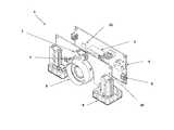
- FIG. 1is an isometric view of a depth camera in accordance with the present invention
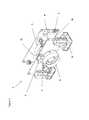
- FIG. 2is a schematic representation of the depth camera of FIG. 1 with predefined volume of interest sub-ranges in accordance with the present invention
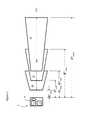
- FIG. 3is a plot of volume of interest sub-range triplet information in accordance with the present invention.
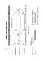
- FIG. 4is a schematic representation of and an ASIC of the depth camera of the present invention.
- a depth camera 1for a Time of Flight (ToF) system, e.g. for a gesture recognition device, includes a light source 2 , e.g. an LED, Laser or other light emitting device with associated drive and control circuitry, for launching a beam of light into an overall Range of Interest (RoI) and Field of View (FoV), a receiving optic with an IR filter, and a depth sensor detector array 3 for receiving and detecting portions of the beam of light reflected off of various moving objects within the RoI and FoV.
- the depth camera 1also includes a power port 4 for connection to a remote or host power supply, and a data port 6 for connection to a host processor.
- a color (RGB) camera 7is also provided, along with variable speed fans 8 for cooling the system.
- the camera 1When considering dynamic range and depth of field, higher frequencies and lower powers work well for short range applications (0.5 mm to 3 m), low frequencies and high powers work well for long range applications (3 m to 5 m), and something in between is better for intermediate range applications (2 m to 4 m).
- the camera 1of the present invention, provides a working range of between 0.5 mm and 5 m or more.
- the RoI and FoVfor the camera 1 according to the present invention, is divided into a plurality of sub-range volumes of interest (VoI), 16 , 17 and 18 , each with their own operating frequency and synchronized with a different light source peak optical power (POP) during a integration subperiod within the camera's frame time to create frequency, POP and integration subperiod pairs or triplets more finely tuned for the plurality of sub-ranges within the camera application's range of interest.
- POPlight source peak optical power
- the summing or aggregation of these sub-range intra-frame time frequency, POP and integration subperiod pairs or tripletscreates a higher dynamic range and sharper depth of field image within the given overall RoI.
- Three VoI'sare illustrated; however, two, four or more VoI's are possible and within the scope of this invention.
- An aggregation processis used to stitch together intra frame depth image fragments generated by the depth camera 1 using optical power, frequency and integration period pairs or triplets into a single or multiple frame composite image(s). Such aggregation could be done by, but not limited to, the simple or weighted averaging of individual pixel values generated by intra frame or multiple frame pairs, triplets, quadruplets, etc. Similarly mean values, mode values, etc. could be used.
- the determination of appropriate frequency, power values and ideally integration subperiodscan be made via estimation, calculation or empirically for static or dynamic scenes, statically, e.g. during an initial set up, or dynamically, e.g. during use.
- An example of a simple static estimationwould be to break the FOV Volume Of Interest (VOI) into a plurality of sections, e.g. two to five or more VoI sub-ranges, in the depth direction and assume that the power required for successive sections would increase moving away from the camera.
- VOIFOV Volume Of Interest
- the appropriate number of VoI sub-rangesis dependent on the application's overall range and depth of field requirements, and typical object reflectivity's in the range, i.e. longer distances and greater target object reflectivity ranges could mean more sections.
- the VoI sub-rangescan have equal ranges, and volumes, e.g. 1.5 m to 3 m, preferably 2 m deep, or they can have different ranges and volumes, e.g. the first volume 16 is smaller than the second volume 17 , which is smaller than the third volume 18 . Typically these sub-ranges or volumes will grow with distance from the camera 1 .
- the VoI sub-rangescan be discreet volumes, e.g. VoI 16 has an R 1 min to R 1 max of from 0.5 m to 1.5 m, VoI 17 has a R 2 min to R 2 max of from 1.5 m to 3 m, and VoI 18 has a R 3 min to R 3 max of from and 3 m to 5 m.
- the VoI sub-rangescan be a series of overlapping volumes, e.g. VoI 16 has an R 1 min to R 1 max of from 0.5 m to 2 m, VoI 17 has a R 2 min to R 2 max of from 1 m to 3 m, and VoI 18 has a R 3 min to R 3 max of from and 2 m to 5 m.
- a frequency f nis selected, e.g. a suitable unambiguous, frequency or the highest (non-aliasing) prime frequency the camera 1 is capable of, within a selected low range of frequencies (10 to 40 MHz) for the farthest VoI sub-range, e.g. VoI 18 .
- the non-aliasing max frequencyis 20 MHz, but 19 MHz, which is the highest prime frequency close to but not higher than 20 MHz, may be the better choice for the farthest VoI subrange 18 , so that erroneous readings do not occur due to the closer subranges in which the frequency might be set to 40 MHz or 60 MHz, thereby creating interfering harmonics. Accordingly, 37 MHz or 59 MHz would likely be better choices for the middle subrange VoI 17 , and 97 MHz, etc. for the nearest subrange VoI 16 . Ideally, the least common multiple of the three frequencies f 1 , f 2 , f n , selected are outside the working range of the camera.
- the POP P n for the farthest VoI sub-rangeis then determined based on the frequency f n and the POP necessary to resolve the required minimum object size at its lowest targeted reflectivity.
- the frequency and POP valuesare modified to optimize performance within the closer VoI sub-ranges, e.g. VoI sub-ranges 16 and 17 , e.g. lower power, higher frequency in successive ranges getting closer to camera.
- the frequency values between the VoI's 16 to 18are at much wider ranges, e.g. greater than +/ ⁇ 30 MHz, 50 MHz and up at least 100 MHz, than prior art systems.
- the frequency f n selectedmight be 10 to 40 MHz, preferably 20 to 25 MHz to avoid distance aliasing in the range, and the POP P n might be determined to be 5 W or more, preferably 1 W or more, most preferably greater than 500 mW, but ideally as low as possible to reduce power requirements.
- the middle VoI sub-range 17can have a frequency f 2 higher than the farthest VoI sub-range 18 , e.g. 30 to 70 MHz, preferably 40 to 50 MHz to avoid distance aliasing within this midrange, with a POP P 2 less than the farthest VoI sub-range 18 , e.g.
- the closest VoI sub-range 16can have a frequency f 1 higher than the other two or more VoI sub-ranges, e.g. 60 MHz or more, preferably 75 MHz or more, but typically as high as possible below the distance aliasing frequency, with a POP P 1 less than the other ranges, e.g. 400 mW or less, preferably less than 250 mW, and most preferably 50 mW or less, but ideally as low as possible.
- the intra-frame integration period Iis divided equally amongst the VoI sub-ranges; however, the intra-frame integration periods I 1 , I 2 , . . . I n can be divided unevenly amongst the frequency/POP pairs to more optimally allocate power within or distribute power to the various VoI sub-ranges.
- Intra-frame integration time, frequency and or powermight be reduced to avoid saturation of more reflective objects with in the range's VOI. For example: an integration period between say 5% and 40%, preferably between 25% and 40%, of the total frame period would be suitable time periods, depending on system requirement.
- the larger VoI sub-ranges and those with longer rangesrequire more time, e.g. a larger percentage of the integration period.
- the light sourcecan be turned off to conserve power and reduce the generation of unwanted heat in the system, as illustrated in FIG. 3 .
- the aggregation of object depth values across these more optimized sub-range intra-frame time frequency, POP and integration time triplets R 1 , R 2 , . . . R nenables the creation of a higher dynamic range, sharper depth of field and more accurate depth image of a given range of interest.
- the pair or triplet valuescan be modified to optimize performance within the second sub-range's VoI, e.g. lower power, higher frequency in successive ranges getting closer to camera.
- the light source power Pcould be reduced and/or the frequency f could be increased and/or the integration period I could be reduced, or any similar weighted combinations of these variables could be changed, using the components and processes described in the below explanation of the 3D camera block diagram, to avoid a saturation issue.
- a darker or less reflective object moving away from the camera 1could trigger modification to a range's VoI triplet to keep the object from disappearing while still in the range.
- the intra-frame triplet variationscould be used in conjunction with an autofocus/zoom lens 9 , with or without an equivalent light source zoom capability.
- a sub-range VoI tripletcould become a quadruplet.
- the FOV/VOIcould be increased or decreased as an application required by the widening or narrowing the FOV/VOI of one of the sub-range VoI's 16 to 18 .
- the sub-range VoI's closer to the camera 1typically require larger FOVs than sub-range VoI's further from the camera 1 .
- Narrowing or widening the camera's FOVhas nearly the same effect as increasing or decreasing POP for a sub-range VoI, the amount of which depends on whether or not the light source is synchronously zoomed with the lens 9 to cover the same FOV.
- the lens and the light sourcecan be zoomed out, which would effectively reduce the per pixel POP and similarly avoid potential object saturation issues.
- the lens 9 and light source 2can be zoomed in to effectively increase per pixel POP. This could significantly reduce the maximum POP and electrical power requirement of the camera 1 throughout its total range.
- the intra-frame triplet, or intra-frame triplet plus zoom lens 9 intra-frame quadruplet variations.could be used in conjunction with lens 9 with variable aperture capability, with or without an equivalent lens or light source zoom capability.
- a sub-range VoI tripletcould become a quadruplet or quintuplet if used with the lens' zoom capability.
- the FOV/VOIcould be increased or decreased as an application required by the widening or narrowing the lens aperture setting of one of the sub-range VoI's 16 to 18 .
- a camera sub-range VoImay require more or less light than the previous or next camera sub-range VoI. Narrowing or widening the camera's aperture has nearly the same effect as increasing or decreasing POP for a sub-range VoI, the amount of which depends on whether or not the light source 2 is synchronously zoomed and or focused with the lens 9 to cover the same FOV.
- the light source 2comprises a laser required to actively illuminate the specified optical field of view within the camera working range with modulated light.
- the light source 2provides the specified wavelength of monochromatic light for the active illumination.
- a typical light source 2comprises a laser, high speed driver circuitry 10 and a diffuser for uniform light distribution within the FOV.
- the laser driver circuit 10is controlled with signals coming from a coprocessor 21 .
- the light source 2is modulated during the integration time of the sensor 3 and is tightly coupled with sensor operation. Care needs to be taken to control the timing and waveform of signals going to the light source 2 and within the light source 2 to produce proper illumination over the operating temperature.
- Light source frequencyis a critical system performance variable and must be selected carefully based on camera operating range with higher frequencies being better for near range applications and lower frequencies being better for long range applications.
- aliasing artifactscan be reduced by proper frequency selection for an application.
- the coprocessor 21can translate phase data to depth data, performs depth calibration, depth data corrections, RGB color processing, compression sensor control, RGB & Z data synchronization, tagging and registration.
- some or all of these above processescould be handled by the camera coprocessor 21 or raw data could be passed through to the host for processing.
- fewer of these processeswill need to be handled by the coprocessor 21 within the camera 1 .
- the choice of coprocessor 21is very much dependent on the target host processing capability. Less intelligent host devices require more in camera processing while more intelligent host devices can be less dependent on in camera processing.
- the above coprocessor 21 and the following 3D imaging related functionscould be implemented in gate level logic and integrated into a single application specific integrated circuit ASIC 21 or implemented in host side software or hardware or any combination in between.
- phase data coming from a depth sensor, raw RGB data coming from a traditional color sensor, and audio coming from a microphone or microphone arraymust be further processed prior to presentation to various host devices, such as PCs, TVs, mobile devices, etc. for display.
- ADCanalog to digital converters
- the raw data streamscan exceed the bandwidth of the host input port, typically USB 2.0 and must therefore be processed and or compressed prior to transport.
- the below described functions of the ASIC 21can be performed faster when implemented in hardware logic as opposed to software running on a host's processor. If the host's processor is required to perform the below mentioned ASIC functions as well as application processing the result can be increased application latency, which can be distracting to a user. Similarly, keeping data flow on chip during processing can increase processing speed and further decrease application latency.
- An embedded microprocessor/controller 22controls the flow of data and command instructions within the ASIC 21 , and turns on or off specific ASIC logic block level functions or functions within ASIC logic blocks.
- the microprocessor 22also controls data and command instruction flow of sensors, i.e. the depth sensor 3 and RGB sensor 7 , and the light source 2 , in particular from the sensor and light source control module 23 .
- the microprocessor 22also supports device level user interfacing, e.g. buttons, switches, display 26 , etc., and supports firmware based processing functions and programmability, e.g. exposure control, gain control, light source frequency and duty cycle control, depth sensor 3 to RGB 7 and light source 2 synchronization, etc.
- I2C 27is a command/instruction bus allowing command and response flow within the ASIC 21 .
- I2C 27is the command, control and feedback mechanism; however, other standard communication, control and feedback standards or proprietary methods could be used.
- Any 3D processor blockcould be integrated into a single chip or parts in any combination of discrete chips.
- the system power supply(not shown) could be a standalone power supply, integrated into the 3D processor or received from a host 28 via an integrated power and data bus such as USB, Firewire, etc.
- Analog to digital converter (ADC) 29converts analog data to digital data for further on chip and host processing.
- One or more Input/Output Port(s) 31supports the input of raw or preprocessed data from the RGB sensor 7 , the depth sensor 3 , an optional microphone 32 , the light source 2 or other data; as well as command, clock or other general purpose input to the ASIC 21 from its peripherals and from the ASIC 21 to its peripherals.
- the input/output port 31also provides processed data output to the display 26 .
- Flash Memory 33stores or buffers data from the various input devices, e.g. depth and RGB sensors 3 and 7 , for the various on chip processing modules, e.g. depth processing module 34 and color processing module 36 .
- RAM 37stores command and control instruction firmware for execution by the microprocessor/controller 22 .
- a Clock/PLL 38provides an internal or externally synchronized clock reference for chip function timing and control.
- the USB Phy 6which could be PCI, MIPI or any other standard or proprietary Phy provides a physical interface from the ASIC 21 to the host device 28 .
- An Audio Codec 41converts raw or preprocessed audio data from mics 32 to an industry standard or proprietary data format for use by the host 28 .
- the Color Processing module 36performs white balancing/color correction, color demosaicing, color space conversion, and other raw or preprocessed RGB data stream related processing functions to the data from the RGB sensor 7 .
- the Depth Processing module 34performs phase to depth data conversion, etc. on raw or preprocessed depth data form the depth sensor 3 .
- a Corrections module 42performs lens, Gama, dark level compensation, sensor defect, scaling, horizontal/vertical flip/rotation, filtering, flicker, dealiasing, binning etc.
- a Compression module 43compresses raw or preprocess RGB, Depth, Audio or other data from the corresponding modules 7 , 3 , 32 to industry standard, e.g. JPEG, MJPEG, H.264, Dolby AC3, etc. or proprietary formats for use by host device 28 .
- industry standarde.g. JPEG, MJPEG, H.264, Dolby AC3, etc. or proprietary formats for use by host device 28 .
- a Data Bus 44transfers data between the functional blocks, e.g. modules 3 , 7 , 32 , memory 33 , 37 and ports 31 of the ASIC 21 under direction of the microprocessor/controller 22 .
- Synchronization, Tagging & Merging module 44tags, synchronizes and multiplexes packetized RGB, Depth and Audio raw or processed data streams from the corresponding sensors 7 , 3 and 32 for transfer and presentation to the host 28 via the USB Phy 6 .
- Calibration and Registration module 46uses algorithms and internal coefficients created from camera measurements made during the calibration phase of camera testing to correlate camera depth values with actual object distance values. Registration is the process of correlating the x & y locations of pixels between the RGB and Depth sensors.
- the microprocessor 22first applies settings for one of the predetermined frequency, power and integration period triplet stored in the RAM 37 or other suitable non-transitory memory. Preferably, the microprocessor 22 then assesses the image quality, such as depth accuracy, and image sharpness, e.g. by determining at least one of: the number of blurred pixels, the number of saturated pixels, and the number of dark pixels, etc., within the field of view and volume of interest sub-range, and comparing the determined number to a predetermined threshold value, based on algorithms stored in non-volatile memory or hard coded in the processor or other chip.
- image qualitysuch as depth accuracy, and image sharpness
- the micro-processor 22then, using other algorithms stored in memory or hard coded in the processor or other chip, calculates appropriate new triplets and triplet sequences for best or improved dynamic range.
- the micro-processor 22then adjusts the clock timing (frequency), light source 2 power level, lens 9 zoom and focus settings corresponding to each sequential triplet, as necessary.
- Image quality based feedback loopsmay or may not be used to validate or monitor sensor 3 , lens 9 or light source 2 actual settings or performance.
- the resulting tripletscould be sequenced in any order and the system could be implemented with a fixed focus lens with appropriate depth of field for the field of view and volume of interest.
- the micro-processor 22then merges the data from each triplet into or calculates a composite frame(s) for transfer to the host device 28 .
- processing and controlcould also be implemented on and performed by the sensor 3 or the raw data could be transferred to the host 28 for processing or in any distributed processing device combination.
- processingcould be performed before, after or during phase to depth calculation. i.e. on phase, depth/range or intermediate data; and before, after or during other (calibration, registration, corrections, compression and audio, RGB & Depth data synchronization, tagging and merging, etc.) data processing activities.
Landscapes
- Engineering & Computer Science (AREA)
- Physics & Mathematics (AREA)
- Computer Networks & Wireless Communication (AREA)
- General Physics & Mathematics (AREA)
- Radar, Positioning & Navigation (AREA)
- Remote Sensing (AREA)
- Electromagnetism (AREA)
- Multimedia (AREA)
- Signal Processing (AREA)
- Studio Devices (AREA)
- Testing, Inspecting, Measuring Of Stereoscopic Televisions And Televisions (AREA)
Abstract
Description
Claims (24)
Priority Applications (1)
| Application Number | Priority Date | Filing Date | Title |
|---|---|---|---|
| US13/757,301US9294754B2 (en) | 2012-02-03 | 2013-02-01 | High dynamic range and depth of field depth camera |
Applications Claiming Priority (2)
| Application Number | Priority Date | Filing Date | Title |
|---|---|---|---|
| US201261594745P | 2012-02-03 | 2012-02-03 | |
| US13/757,301US9294754B2 (en) | 2012-02-03 | 2013-02-01 | High dynamic range and depth of field depth camera |
Publications (2)
| Publication Number | Publication Date |
|---|---|
| US20130201288A1 US20130201288A1 (en) | 2013-08-08 |
| US9294754B2true US9294754B2 (en) | 2016-03-22 |
Family
ID=48902539
Family Applications (1)
| Application Number | Title | Priority Date | Filing Date |
|---|---|---|---|
| US13/757,301Expired - Fee RelatedUS9294754B2 (en) | 2012-02-03 | 2013-02-01 | High dynamic range and depth of field depth camera |
Country Status (1)
| Country | Link |
|---|---|
| US (1) | US9294754B2 (en) |
Cited By (17)
| Publication number | Priority date | Publication date | Assignee | Title |
|---|---|---|---|---|
| US20150116459A1 (en)* | 2013-10-25 | 2015-04-30 | Lips Incorporation | Sensing device and signal processing method thereof |
| US20160050346A1 (en)* | 2014-06-13 | 2016-02-18 | Lips Corporation | Integrated depth camera |
| US20160373722A1 (en)* | 2015-06-19 | 2016-12-22 | Amazon Technologies, Inc. | Steganographic depth images |
| US9786080B1 (en)* | 2015-07-02 | 2017-10-10 | Yesvideo, Inc. | 2D/3D image scanning and compositing |
| US10212306B1 (en) | 2016-03-23 | 2019-02-19 | Amazon Technologies, Inc. | Steganographic camera communication |
| US10241244B2 (en) | 2016-07-29 | 2019-03-26 | Lumentum Operations Llc | Thin film total internal reflection diffraction grating for single polarization or dual polarization |
| CN110312117A (en)* | 2019-06-12 | 2019-10-08 | 北京达佳互联信息技术有限公司 | Method for refreshing data and device |
| WO2019199645A1 (en) | 2018-04-09 | 2019-10-17 | Sense Photonics, Inc. | Automatic gain control for lidar for autonomous vehicles |
| WO2020058264A1 (en)* | 2018-09-19 | 2020-03-26 | Sony Semiconductor Solutions Corporation | Time of flight apparatus and method |
| US10873738B2 (en) | 2016-03-03 | 2020-12-22 | 4D Intellectual Properties, Llc | Multi-frame range gating for lighting-invariant depth maps for in-motion applications and attenuating environments |
| US10996320B2 (en)* | 2017-07-11 | 2021-05-04 | Sony Semiconductor Solutions Corporation | Electronic device and control method of electronic device |
| US11001979B2 (en) | 2018-08-13 | 2021-05-11 | Vergence Automation, Inc. | Methods and apparatus for ultrawide entrance angle reflective articles for use with autonomous vehicle machine vision systems |
| US11041957B2 (en) | 2018-06-25 | 2021-06-22 | Toyota Motor Engineering & Manufacturing North America, Inc. | Systems and methods for mitigating effects of high-reflectivity objects in LiDAR data |
| US11514594B2 (en) | 2019-10-30 | 2022-11-29 | Vergence Automation, Inc. | Composite imaging systems using a focal plane array with in-pixel analog storage elements |
| US11606517B1 (en) | 2021-06-07 | 2023-03-14 | Waymo Llc | Enhanced depth of focus cameras using variable apertures and pixel binning |
| US11762133B1 (en) | 2018-09-13 | 2023-09-19 | Vergence Automation, Inc. | Retroreflective materials and articles incorporating near-ideal total internal retroreflective elements |
| US12230649B2 (en) | 2020-05-19 | 2025-02-18 | Vergence Automation, Inc. | AI system on chip (SOC) for robotics vision applications |
Families Citing this family (58)
| Publication number | Priority date | Publication date | Assignee | Title |
|---|---|---|---|---|
| US9779546B2 (en) | 2012-05-04 | 2017-10-03 | Intermec Ip Corp. | Volume dimensioning systems and methods |
| US10007858B2 (en) | 2012-05-15 | 2018-06-26 | Honeywell International Inc. | Terminals and methods for dimensioning objects |
| TWI471630B (en)* | 2012-06-01 | 2015-02-01 | Hon Hai Prec Ind Co Ltd | Auto-focus system and method of a digital camera |
| US10321127B2 (en) | 2012-08-20 | 2019-06-11 | Intermec Ip Corp. | Volume dimensioning system calibration systems and methods |
| US9939259B2 (en) | 2012-10-04 | 2018-04-10 | Hand Held Products, Inc. | Measuring object dimensions using mobile computer |
| US20140104413A1 (en) | 2012-10-16 | 2014-04-17 | Hand Held Products, Inc. | Integrated dimensioning and weighing system |
| US9080856B2 (en) | 2013-03-13 | 2015-07-14 | Intermec Ip Corp. | Systems and methods for enhancing dimensioning, for example volume dimensioning |
| US10228452B2 (en) | 2013-06-07 | 2019-03-12 | Hand Held Products, Inc. | Method of error correction for 3D imaging device |
| US10203399B2 (en) | 2013-11-12 | 2019-02-12 | Big Sky Financial Corporation | Methods and apparatus for array based LiDAR systems with reduced interference |
| US9360554B2 (en) | 2014-04-11 | 2016-06-07 | Facet Technology Corp. | Methods and apparatus for object detection and identification in a multiple detector lidar array |
| US9823059B2 (en) | 2014-08-06 | 2017-11-21 | Hand Held Products, Inc. | Dimensioning system with guided alignment |
| US10810715B2 (en) | 2014-10-10 | 2020-10-20 | Hand Held Products, Inc | System and method for picking validation |
| US9779276B2 (en) | 2014-10-10 | 2017-10-03 | Hand Held Products, Inc. | Depth sensor based auto-focus system for an indicia scanner |
| US10775165B2 (en) | 2014-10-10 | 2020-09-15 | Hand Held Products, Inc. | Methods for improving the accuracy of dimensioning-system measurements |
| US9897434B2 (en) | 2014-10-21 | 2018-02-20 | Hand Held Products, Inc. | Handheld dimensioning system with measurement-conformance feedback |
| US9752864B2 (en) | 2014-10-21 | 2017-09-05 | Hand Held Products, Inc. | Handheld dimensioning system with feedback |
| US9557166B2 (en) | 2014-10-21 | 2017-01-31 | Hand Held Products, Inc. | Dimensioning system with multipath interference mitigation |
| US9762793B2 (en) | 2014-10-21 | 2017-09-12 | Hand Held Products, Inc. | System and method for dimensioning |
| US9330464B1 (en) | 2014-12-12 | 2016-05-03 | Microsoft Technology Licensing, Llc | Depth camera feedback |
| US9581696B2 (en)* | 2014-12-22 | 2017-02-28 | Google Inc. | Image sensor and light source driver integrated in a same semiconductor package |
| US9635231B2 (en) | 2014-12-22 | 2017-04-25 | Google Inc. | Time-of-flight camera system and method to improve measurement quality of weak field-of-view signal regions |
| US10036801B2 (en) | 2015-03-05 | 2018-07-31 | Big Sky Financial Corporation | Methods and apparatus for increased precision and improved range in a multiple detector LiDAR array |
| US9786101B2 (en) | 2015-05-19 | 2017-10-10 | Hand Held Products, Inc. | Evaluating image values |
| US10066982B2 (en) | 2015-06-16 | 2018-09-04 | Hand Held Products, Inc. | Calibrating a volume dimensioner |
| US20160377414A1 (en) | 2015-06-23 | 2016-12-29 | Hand Held Products, Inc. | Optical pattern projector |
| US9857167B2 (en) | 2015-06-23 | 2018-01-02 | Hand Held Products, Inc. | Dual-projector three-dimensional scanner |
| US9835486B2 (en) | 2015-07-07 | 2017-12-05 | Hand Held Products, Inc. | Mobile dimensioner apparatus for use in commerce |
| EP3118576B1 (en) | 2015-07-15 | 2018-09-12 | Hand Held Products, Inc. | Mobile dimensioning device with dynamic accuracy compatible with nist standard |
| US10094650B2 (en) | 2015-07-16 | 2018-10-09 | Hand Held Products, Inc. | Dimensioning and imaging items |
| US20170017301A1 (en) | 2015-07-16 | 2017-01-19 | Hand Held Products, Inc. | Adjusting dimensioning results using augmented reality |
| WO2017061104A1 (en) | 2015-10-09 | 2017-04-13 | パナソニックIpマネジメント株式会社 | Imaging apparatus and solid-state image element used for same |
| EP3156825B1 (en)* | 2015-10-16 | 2018-08-29 | Hand Held Products, Inc. | Dimensioning system with multipath interference mitigation |
| US10249030B2 (en) | 2015-10-30 | 2019-04-02 | Hand Held Products, Inc. | Image transformation for indicia reading |
| US10225544B2 (en) | 2015-11-19 | 2019-03-05 | Hand Held Products, Inc. | High resolution dot pattern |
| US10025314B2 (en) | 2016-01-27 | 2018-07-17 | Hand Held Products, Inc. | Vehicle positioning and object avoidance |
| US10339352B2 (en) | 2016-06-03 | 2019-07-02 | Hand Held Products, Inc. | Wearable metrological apparatus |
| US9940721B2 (en) | 2016-06-10 | 2018-04-10 | Hand Held Products, Inc. | Scene change detection in a dimensioner |
| US10163216B2 (en) | 2016-06-15 | 2018-12-25 | Hand Held Products, Inc. | Automatic mode switching in a volume dimensioner |
| US10742390B2 (en)* | 2016-07-13 | 2020-08-11 | Novatek Microelectronics Corp. | Method of improving clock recovery and related device |
| US10909708B2 (en) | 2016-12-09 | 2021-02-02 | Hand Held Products, Inc. | Calibrating a dimensioner using ratios of measurable parameters of optic ally-perceptible geometric elements |
| US11047672B2 (en) | 2017-03-28 | 2021-06-29 | Hand Held Products, Inc. | System for optically dimensioning |
| CN109314776B (en)* | 2017-05-17 | 2021-02-26 | 深圳配天智能技术研究院有限公司 | Image processing method, image processing apparatus, and storage medium |
| US10733748B2 (en) | 2017-07-24 | 2020-08-04 | Hand Held Products, Inc. | Dual-pattern optical 3D dimensioning |
| US11340339B2 (en) | 2017-12-22 | 2022-05-24 | Waymo Llc | Systems and methods for adaptive range coverage using LIDAR |
| US10999524B1 (en)* | 2018-04-12 | 2021-05-04 | Amazon Technologies, Inc. | Temporal high dynamic range imaging using time-of-flight cameras |
| US10584962B2 (en) | 2018-05-01 | 2020-03-10 | Hand Held Products, Inc | System and method for validating physical-item security |
| US10708484B2 (en) | 2018-06-20 | 2020-07-07 | Amazon Technologies, Inc. | Detecting interference between time-of-flight cameras using modified image sensor arrays |
| US10681338B1 (en) | 2018-07-24 | 2020-06-09 | Amazon Technologies, Inc. | Detecting interference in depth images captured using overlapping depth cameras |
| CN109286806A (en)* | 2018-09-11 | 2019-01-29 | Oppo广东移动通信有限公司 | Deep acquisition module and mobile terminal |
| US10915783B1 (en) | 2018-12-14 | 2021-02-09 | Amazon Technologies, Inc. | Detecting and locating actors in scenes based on degraded or supersaturated depth data |
| WO2020223879A1 (en)* | 2019-05-06 | 2020-11-12 | 深圳市大疆创新科技有限公司 | Distance measurement apparatus and mobile platform |
| US11639846B2 (en) | 2019-09-27 | 2023-05-02 | Honeywell International Inc. | Dual-pattern optical 3D dimensioning |
| WO2021065138A1 (en)* | 2019-10-01 | 2021-04-08 | パナソニックIpマネジメント株式会社 | Distance measurement device and control method |
| EP4014066A4 (en)* | 2019-12-11 | 2023-01-25 | Samsung Electronics Co., Ltd. | Electronic apparatus and method for controlling thereof |
| WO2021193645A1 (en)* | 2020-03-24 | 2021-09-30 | 株式会社小糸製作所 | Gating camera, sensing system, and vehicle lamp |
| US12025701B2 (en)* | 2020-10-12 | 2024-07-02 | Guangzhou Woya Laideling Technology Co., Ltd. | Dynamic signal control in flash LiDAR |
| CN116868026A (en)* | 2021-03-22 | 2023-10-10 | 深圳市大疆创新科技有限公司 | Range finding device, imaging device and cloud platform |
| DE102021130999A1 (en)* | 2021-11-25 | 2023-05-25 | Kuka Deutschland Gmbh | Process, laser-optical detection system and robot workstation |
Citations (2)
| Publication number | Priority date | Publication date | Assignee | Title |
|---|---|---|---|---|
| US20020015144A1 (en)* | 2000-05-02 | 2002-02-07 | Asahi Kogaku Kogyo Kabushiki Kaisha | Three-dimensional image capturing device |
| US20090273770A1 (en)* | 2008-04-30 | 2009-11-05 | Honeywell International Inc. | Systems and methods for safe laser imaging, detection and ranging (lidar) operation |
- 2013
- 2013-02-01USUS13/757,301patent/US9294754B2/ennot_activeExpired - Fee Related
Patent Citations (2)
| Publication number | Priority date | Publication date | Assignee | Title |
|---|---|---|---|---|
| US20020015144A1 (en)* | 2000-05-02 | 2002-02-07 | Asahi Kogaku Kogyo Kabushiki Kaisha | Three-dimensional image capturing device |
| US20090273770A1 (en)* | 2008-04-30 | 2009-11-05 | Honeywell International Inc. | Systems and methods for safe laser imaging, detection and ranging (lidar) operation |
Cited By (33)
| Publication number | Priority date | Publication date | Assignee | Title |
|---|---|---|---|---|
| US20150116459A1 (en)* | 2013-10-25 | 2015-04-30 | Lips Incorporation | Sensing device and signal processing method thereof |
| US20160050346A1 (en)* | 2014-06-13 | 2016-02-18 | Lips Corporation | Integrated depth camera |
| US9420149B2 (en)* | 2014-06-13 | 2016-08-16 | Lips Corporation | Integrated depth camera |
| US20160373722A1 (en)* | 2015-06-19 | 2016-12-22 | Amazon Technologies, Inc. | Steganographic depth images |
| US10158840B2 (en)* | 2015-06-19 | 2018-12-18 | Amazon Technologies, Inc. | Steganographic depth images |
| US9786080B1 (en)* | 2015-07-02 | 2017-10-10 | Yesvideo, Inc. | 2D/3D image scanning and compositing |
| US10210644B1 (en) | 2015-07-02 | 2019-02-19 | Yesvideo, Inc. | Image capture using target area illumination |
| US11838626B2 (en) | 2016-03-03 | 2023-12-05 | 4D Intellectual Properties, Llc | Methods and apparatus for an active pulsed 4D camera for image acquisition and analysis |
| US10873738B2 (en) | 2016-03-03 | 2020-12-22 | 4D Intellectual Properties, Llc | Multi-frame range gating for lighting-invariant depth maps for in-motion applications and attenuating environments |
| US12418719B2 (en) | 2016-03-03 | 2025-09-16 | 4D Intellectual Properties, Llc | Vehicle headlamp lighting control module for adas and autonomous vehicles |
| US11477363B2 (en) | 2016-03-03 | 2022-10-18 | 4D Intellectual Properties, Llc | Intelligent control module for utilizing exterior lighting in an active imaging system |
| US12096121B2 (en) | 2016-03-03 | 2024-09-17 | 4D Intellectual Properties, Llc | Precision reflectivity and ambient light removal for a geiger mode/single photon active sensor system |
| US10778867B1 (en) | 2016-03-23 | 2020-09-15 | Amazon Technologies, Inc. | Steganographic camera communication |
| US10212306B1 (en) | 2016-03-23 | 2019-02-19 | Amazon Technologies, Inc. | Steganographic camera communication |
| US10802183B2 (en) | 2016-07-29 | 2020-10-13 | Lumentum Operations Llc | Thin film total internal reflection diffraction grating for single polarization or dual polarization |
| US10241244B2 (en) | 2016-07-29 | 2019-03-26 | Lumentum Operations Llc | Thin film total internal reflection diffraction grating for single polarization or dual polarization |
| US10996320B2 (en)* | 2017-07-11 | 2021-05-04 | Sony Semiconductor Solutions Corporation | Electronic device and control method of electronic device |
| US12085675B2 (en) | 2018-04-09 | 2024-09-10 | Sense Photonics, Inc. | Automatic gain control for LIDAR for autonomous vehicles |
| EP3756032A4 (en)* | 2018-04-09 | 2021-12-01 | Sense Photonics, Inc. | Automatic gain control for lidar for autonomous vehicles |
| WO2019199645A1 (en) | 2018-04-09 | 2019-10-17 | Sense Photonics, Inc. | Automatic gain control for lidar for autonomous vehicles |
| US11041957B2 (en) | 2018-06-25 | 2021-06-22 | Toyota Motor Engineering & Manufacturing North America, Inc. | Systems and methods for mitigating effects of high-reflectivity objects in LiDAR data |
| US11001979B2 (en) | 2018-08-13 | 2021-05-11 | Vergence Automation, Inc. | Methods and apparatus for ultrawide entrance angle reflective articles for use with autonomous vehicle machine vision systems |
| US11505903B2 (en) | 2018-08-13 | 2022-11-22 | Vergence Automation, Inc. | Methods and apparatus for ultra wide entrance angle reflective articles for use with autonomous vehicle machine vision systems |
| US11762133B1 (en) | 2018-09-13 | 2023-09-19 | Vergence Automation, Inc. | Retroreflective materials and articles incorporating near-ideal total internal retroreflective elements |
| US12072515B2 (en) | 2018-09-13 | 2024-08-27 | Vergence Automation, Inc. | Retroreflective materials and articles incorporating near-ideal total internal retroreflective elements |
| WO2020058264A1 (en)* | 2018-09-19 | 2020-03-26 | Sony Semiconductor Solutions Corporation | Time of flight apparatus and method |
| US12222455B2 (en) | 2018-09-19 | 2025-02-11 | Sony Semiconductor Solutions Corporation | Time of flight apparatus and method |
| CN110312117B (en)* | 2019-06-12 | 2021-06-18 | 北京达佳互联信息技术有限公司 | Data refreshing method and device |
| CN110312117A (en)* | 2019-06-12 | 2019-10-08 | 北京达佳互联信息技术有限公司 | Method for refreshing data and device |
| US11514594B2 (en) | 2019-10-30 | 2022-11-29 | Vergence Automation, Inc. | Composite imaging systems using a focal plane array with in-pixel analog storage elements |
| US12230649B2 (en) | 2020-05-19 | 2025-02-18 | Vergence Automation, Inc. | AI system on chip (SOC) for robotics vision applications |
| US11606517B1 (en) | 2021-06-07 | 2023-03-14 | Waymo Llc | Enhanced depth of focus cameras using variable apertures and pixel binning |
| US12143734B1 (en) | 2021-06-07 | 2024-11-12 | Waymo Llc | Enhanced depth of focus cameras using variable apertures and pixel binning |
Also Published As
| Publication number | Publication date |
|---|---|
| US20130201288A1 (en) | 2013-08-08 |
Similar Documents
| Publication | Publication Date | Title |
|---|---|---|
| US9294754B2 (en) | High dynamic range and depth of field depth camera | |
| US10949647B2 (en) | System and method of efficient illuminator-sensor synchronization to capture images | |
| US11330199B2 (en) | Method and system of adaptable exposure control and light projection for cameras | |
| US9516295B2 (en) | Systems and methods for multi-channel imaging based on multiple exposure settings | |
| US10863155B2 (en) | Reduction of banding artifacts in image processing | |
| CN104717435B (en) | Camera device and image capture method | |
| US10009554B1 (en) | Method and system for using light emission by a depth-sensing camera to capture video images under low-light conditions | |
| US9578224B2 (en) | System and method for enhanced monoimaging | |
| RU2627933C2 (en) | Image capturing device and device control method | |
| US20130278738A1 (en) | Image processing apparatus and image processing method | |
| JP2021500820A (en) | Imaging control method and imaging device | |
| US8743226B2 (en) | Exposure adjustment method for night-vision camera | |
| WO2016203727A1 (en) | Medical image processing apparatus, medical image processing method, and medical observation system | |
| US10200623B1 (en) | Image capture setting determination in flash photography operations | |
| US10663593B2 (en) | Projector apparatus with distance image acquisition device and projection method | |
| JP6950698B2 (en) | Imaging control device, imaging control method and imaging device | |
| US20120050490A1 (en) | Method and system for depth-information based auto-focusing for a monoscopic video camera | |
| EP3609175B1 (en) | Apparatus and method for generating moving image data including multiple section images in electronic device | |
| US9838667B2 (en) | Image pickup apparatus, image pickup method, and non-transitory computer-readable medium | |
| US20200145641A1 (en) | Image processing apparatus and method | |
| WO2016055090A1 (en) | Microscope and method for obtaining a high dynamic range synthesized image of an object | |
| US20210400252A1 (en) | Imaging method, imaging system, manufacturing system, and method for manufacturing a product | |
| US20100039561A1 (en) | System, method, computer-readable medium, and user interface for displaying light radiation | |
| CN116208851B (en) | Image processing method and related device | |
| US20110243442A1 (en) | Video Camera for Acquiring Images with Varying Spatio-Temporal Resolutions |
Legal Events
| Date | Code | Title | Description |
|---|---|---|---|
| AS | Assignment | Owner name:JDS UNIPHASE CORPORATION, CALIFORNIA Free format text:ASSIGNMENT OF ASSIGNORS INTEREST;ASSIGNORS:BILLERBECK, BRYED;TIEN, AN-CHUN;MORALES, LUCAS;SIGNING DATES FROM 20130129 TO 20130329;REEL/FRAME:030151/0382 | |
| AS | Assignment | Owner name:LUMENTUM OPERATIONS LLC, CALIFORNIA Free format text:ASSIGNMENT OF ASSIGNORS INTEREST;ASSIGNOR:JDS UNIPHASE CORPORATION;REEL/FRAME:036420/0340 Effective date:20150731 | |
| FEPP | Fee payment procedure | Free format text:PAYOR NUMBER ASSIGNED (ORIGINAL EVENT CODE: ASPN); ENTITY STATUS OF PATENT OWNER: LARGE ENTITY | |
| AS | Assignment | Owner name:LUMENTUM OPERATIONS LLC, CALIFORNIA Free format text:CORRECTIVE ASSIGNMENT TO CORRECT THE PATENTS LISTED ON PAGE A-A33 PREVIOUSLY RECORDED ON REEL 036420 FRAME 0340. ASSIGNOR(S) HEREBY CONFIRMS THE PATENT NUMBERS 7,868,247 AND 6,476,312 WERE LISTED IN ERROR AND SHOULD BE REMOVED;ASSIGNOR:JDS UNIPHASE CORPORATION;REEL/FRAME:037562/0513 Effective date:20150731 Owner name:LUMENTUM OPERATIONS LLC, CALIFORNIA Free format text:CORRECTIVE ASSIGNMENT TO CORRECT INCORRECT PATENTS 7,868,247 AND 6,476,312 ON PAGE A-A33 PREVIOUSLY RECORDED ON REEL 036420 FRAME 0340. ASSIGNOR(S) HEREBY CONFIRMS THE ASSIGNMENT;ASSIGNOR:JDS UNIPHASE CORPORATION;REEL/FRAME:037562/0513 Effective date:20150731 | |
| AS | Assignment | Owner name:LUMENTUM OPERATIONS LLC, CALIFORNIA Free format text:CORRECTIVE ASSIGNMENT TO CORRECT THE PATENTS LISTED ON PAGE A-A33 PATENT NUMBERS 7,868,247 AND 6,476,312 WERE LISTED IN ERROR AND SHOULD BE REMOVED. PREVIOUSLY RECORDED ON REEL 036420 FRAME 0340. ASSIGNOR(S) HEREBY CONFIRMS THE ASSIGNMENT;ASSIGNOR:JDS UNIPHASE CORPORATION;REEL/FRAME:037627/0641 Effective date:20150731 Owner name:LUMENTUM OPERATIONS LLC, CALIFORNIA Free format text:CORRECTIVE ASSIGNMENT TO CORRECT PATENTS 7,868,247 AND 6,476,312 LISTED ON PAGE A-A33 PREVIOUSLY RECORDED ON REEL 036420 FRAME 0340. ASSIGNOR(S) HEREBY CONFIRMS THE ASSIGNMENT;ASSIGNOR:JDS UNIPHASE CORPORATION;REEL/FRAME:037627/0641 Effective date:20150731 | |
| STCF | Information on status: patent grant | Free format text:PATENTED CASE | |
| CC | Certificate of correction | ||
| AS | Assignment | Owner name:DEUTSCHE BANK AG NEW YORK BRANCH, AS COLLATERAL AGENT, NEW YORK Free format text:PATENT SECURITY AGREEMENT;ASSIGNORS:LUMENTUM OPERATIONS LLC;OCLARO FIBER OPTICS, INC.;OCLARO, INC.;REEL/FRAME:047788/0511 Effective date:20181210 Owner name:DEUTSCHE BANK AG NEW YORK BRANCH, AS COLLATERAL AG Free format text:PATENT SECURITY AGREEMENT;ASSIGNORS:LUMENTUM OPERATIONS LLC;OCLARO FIBER OPTICS, INC.;OCLARO, INC.;REEL/FRAME:047788/0511 Effective date:20181210 | |
| MAFP | Maintenance fee payment | Free format text:PAYMENT OF MAINTENANCE FEE, 4TH YEAR, LARGE ENTITY (ORIGINAL EVENT CODE: M1551); ENTITY STATUS OF PATENT OWNER: LARGE ENTITY Year of fee payment:4 | |
| AS | Assignment | Owner name:LUMENTUM OPERATIONS LLC, CALIFORNIA Free format text:RELEASE BY SECURED PARTY;ASSIGNOR:DEUTSCHE AG NEW YORK BRANCH;REEL/FRAME:051287/0556 Effective date:20191212 Owner name:OCLARO FIBER OPTICS, INC., CALIFORNIA Free format text:RELEASE BY SECURED PARTY;ASSIGNOR:DEUTSCHE AG NEW YORK BRANCH;REEL/FRAME:051287/0556 Effective date:20191212 Owner name:OCLARO, INC., CALIFORNIA Free format text:RELEASE BY SECURED PARTY;ASSIGNOR:DEUTSCHE AG NEW YORK BRANCH;REEL/FRAME:051287/0556 Effective date:20191212 | |
| FEPP | Fee payment procedure | Free format text:MAINTENANCE FEE REMINDER MAILED (ORIGINAL EVENT CODE: REM.); ENTITY STATUS OF PATENT OWNER: LARGE ENTITY | |
| LAPS | Lapse for failure to pay maintenance fees | Free format text:PATENT EXPIRED FOR FAILURE TO PAY MAINTENANCE FEES (ORIGINAL EVENT CODE: EXP.); ENTITY STATUS OF PATENT OWNER: LARGE ENTITY | |
| STCH | Information on status: patent discontinuation | Free format text:PATENT EXPIRED DUE TO NONPAYMENT OF MAINTENANCE FEES UNDER 37 CFR 1.362 | |
| FP | Lapsed due to failure to pay maintenance fee | Effective date:20240322 |