US9294218B2 - Rate prediction in fractional reuse systems - Google Patents
Rate prediction in fractional reuse systemsDownload PDFInfo
- Publication number
- US9294218B2 US9294218B2US11/168,904US16890405AUS9294218B2US 9294218 B2US9294218 B2US 9294218B2US 16890405 AUS16890405 AUS 16890405AUS 9294218 B2US9294218 B2US 9294218B2
- Authority
- US
- United States
- Prior art keywords
- subcarrier
- channel quality
- determining
- quality indicator
- reuse set
- Prior art date
- Legal status (The legal status is an assumption and is not a legal conclusion. Google has not performed a legal analysis and makes no representation as to the accuracy of the status listed.)
- Expired - Fee Related, expires
Links
- 238000004891communicationMethods0.000claimsabstractdescription71
- 238000000034methodMethods0.000claimsabstractdescription59
- 239000000969carrierSubstances0.000claimsabstractdescription35
- 230000005540biological transmissionEffects0.000claimsdescription63
- 238000004422calculation algorithmMethods0.000claimsdescription38
- 230000008569processEffects0.000claimsdescription12
- 230000000977initiatory effectEffects0.000claimsdescription3
- 238000013468resource allocationMethods0.000claims1
- 238000005259measurementMethods0.000description13
- 230000002441reversible effectEffects0.000description11
- 238000010586diagramMethods0.000description9
- 238000012935AveragingMethods0.000description3
- 235000008694Humulus lupulusNutrition0.000description3
- 238000007476Maximum LikelihoodMethods0.000description2
- 230000015556catabolic processEffects0.000description2
- 230000001413cellular effectEffects0.000description2
- 238000006731degradation reactionMethods0.000description2
- 238000005562fadingMethods0.000description2
- 230000002452interceptive effectEffects0.000description2
- 230000036961partial effectEffects0.000description2
- 238000012545processingMethods0.000description2
- 230000003595spectral effectEffects0.000description2
- 230000003068static effectEffects0.000description2
- 239000011800void materialSubstances0.000description2
- 230000009471actionEffects0.000description1
- 230000008859changeEffects0.000description1
- 238000012937correctionMethods0.000description1
- 125000004122cyclic groupChemical group0.000description1
- 230000007423decreaseEffects0.000description1
- 238000001514detection methodMethods0.000description1
- 230000006870functionEffects0.000description1
- 238000012886linear functionMethods0.000description1
- 238000013507mappingMethods0.000description1
- 238000012986modificationMethods0.000description1
- 230000004048modificationEffects0.000description1
- 230000002829reductive effectEffects0.000description1
- 230000011664signalingEffects0.000description1
- 238000004088simulationMethods0.000description1
- 238000001228spectrumMethods0.000description1
- 230000007480spreadingEffects0.000description1
- 230000008685targetingEffects0.000description1
Images


Classifications
- H—ELECTRICITY
- H04—ELECTRIC COMMUNICATION TECHNIQUE
- H04L—TRANSMISSION OF DIGITAL INFORMATION, e.g. TELEGRAPHIC COMMUNICATION
- H04L1/00—Arrangements for detecting or preventing errors in the information received
- H04L1/0001—Systems modifying transmission characteristics according to link quality, e.g. power backoff
- H04L1/0015—Systems modifying transmission characteristics according to link quality, e.g. power backoff characterised by the adaptation strategy
- H—ELECTRICITY
- H04—ELECTRIC COMMUNICATION TECHNIQUE
- H04L—TRANSMISSION OF DIGITAL INFORMATION, e.g. TELEGRAPHIC COMMUNICATION
- H04L1/00—Arrangements for detecting or preventing errors in the information received
- H04L1/0001—Systems modifying transmission characteristics according to link quality, e.g. power backoff
- H04L1/0002—Systems modifying transmission characteristics according to link quality, e.g. power backoff by adapting the transmission rate
- H—ELECTRICITY
- H04—ELECTRIC COMMUNICATION TECHNIQUE
- H04L—TRANSMISSION OF DIGITAL INFORMATION, e.g. TELEGRAPHIC COMMUNICATION
- H04L1/00—Arrangements for detecting or preventing errors in the information received
- H04L1/0001—Systems modifying transmission characteristics according to link quality, e.g. power backoff
- H04L1/0006—Systems modifying transmission characteristics according to link quality, e.g. power backoff by adapting the transmission format
- H—ELECTRICITY
- H04—ELECTRIC COMMUNICATION TECHNIQUE
- H04L—TRANSMISSION OF DIGITAL INFORMATION, e.g. TELEGRAPHIC COMMUNICATION
- H04L1/00—Arrangements for detecting or preventing errors in the information received
- H04L1/20—Arrangements for detecting or preventing errors in the information received using signal quality detector
- H—ELECTRICITY
- H04—ELECTRIC COMMUNICATION TECHNIQUE
- H04L—TRANSMISSION OF DIGITAL INFORMATION, e.g. TELEGRAPHIC COMMUNICATION
- H04L5/00—Arrangements affording multiple use of the transmission path
- H04L5/0001—Arrangements for dividing the transmission path
- H04L5/0003—Two-dimensional division
- H04L5/0005—Time-frequency
- H04L5/0007—Time-frequency the frequencies being orthogonal, e.g. OFDM(A) or DMT
- H04L5/0012—Hopping in multicarrier systems
- H—ELECTRICITY
- H04—ELECTRIC COMMUNICATION TECHNIQUE
- H04L—TRANSMISSION OF DIGITAL INFORMATION, e.g. TELEGRAPHIC COMMUNICATION
- H04L5/00—Arrangements affording multiple use of the transmission path
- H04L5/003—Arrangements for allocating sub-channels of the transmission path
- H04L5/0058—Allocation criteria
- H04L5/006—Quality of the received signal, e.g. BER, SNR, water filling
- H—ELECTRICITY
- H04—ELECTRIC COMMUNICATION TECHNIQUE
- H04W—WIRELESS COMMUNICATION NETWORKS
- H04W16/00—Network planning, e.g. coverage or traffic planning tools; Network deployment, e.g. resource partitioning or cells structures
- H04W16/02—Resource partitioning among network components, e.g. reuse partitioning
- H04W16/12—Fixed resource partitioning
- H—ELECTRICITY
- H04—ELECTRIC COMMUNICATION TECHNIQUE
- H04W—WIRELESS COMMUNICATION NETWORKS
- H04W28/00—Network traffic management; Network resource management
- H04W28/16—Central resource management; Negotiation of resources or communication parameters, e.g. negotiating bandwidth or QoS [Quality of Service]
- H04W28/18—Negotiating wireless communication parameters
- H04W28/22—Negotiating communication rate
- H—ELECTRICITY
- H04—ELECTRIC COMMUNICATION TECHNIQUE
- H04L—TRANSMISSION OF DIGITAL INFORMATION, e.g. TELEGRAPHIC COMMUNICATION
- H04L1/00—Arrangements for detecting or preventing errors in the information received
- H04L1/0001—Systems modifying transmission characteristics according to link quality, e.g. power backoff
- H04L1/0009—Systems modifying transmission characteristics according to link quality, e.g. power backoff by adapting the channel coding
- H—ELECTRICITY
- H04—ELECTRIC COMMUNICATION TECHNIQUE
- H04L—TRANSMISSION OF DIGITAL INFORMATION, e.g. TELEGRAPHIC COMMUNICATION
- H04L1/00—Arrangements for detecting or preventing errors in the information received
- H04L1/0001—Systems modifying transmission characteristics according to link quality, e.g. power backoff
- H04L1/0023—Systems modifying transmission characteristics according to link quality, e.g. power backoff characterised by the signalling
- H04L1/0026—Transmission of channel quality indication
- H—ELECTRICITY
- H04—ELECTRIC COMMUNICATION TECHNIQUE
- H04L—TRANSMISSION OF DIGITAL INFORMATION, e.g. TELEGRAPHIC COMMUNICATION
- H04L1/00—Arrangements for detecting or preventing errors in the information received
- H04L1/12—Arrangements for detecting or preventing errors in the information received by using return channel
- H04L1/16—Arrangements for detecting or preventing errors in the information received by using return channel in which the return channel carries supervisory signals, e.g. repetition request signals
- H04L1/18—Automatic repetition systems, e.g. Van Duuren systems
- H04L1/1812—Hybrid protocols; Hybrid automatic repeat request [HARQ]
- H—ELECTRICITY
- H04—ELECTRIC COMMUNICATION TECHNIQUE
- H04L—TRANSMISSION OF DIGITAL INFORMATION, e.g. TELEGRAPHIC COMMUNICATION
- H04L27/00—Modulated-carrier systems
- H04L27/26—Systems using multi-frequency codes
- H04L27/2601—Multicarrier modulation systems
Definitions
- the disclosurerelates to the field of wireless communications. More particularly, the disclosure relates to rate prediction in a wireless communication system.
- Wireless communication systemsare often configured as a network of wireless base stations communicating with one or more mobile wireless terminals.
- Each of the wireless base stationscan operate in a unique environment relative to any of the other base stations.
- a base stationcan be configured to support a metropolitan coverage area having numerous high rise buildings with a high density of potential users.
- Another base station coupled to the same communication networkcan be configured to support a relatively sparsely populated coverage area that is substantially void of terrain variations that can affect the signal quality.
- a first wireless base stationcan be configured to support a coverage area that includes numerous potential interfering sources, while a second base station can be configured to support a coverage area largely void of interfering sources.
- Signal quality experienced by a particular user terminal within a base station coverage areacan also vary based on a physical as well as an electrical environment.
- Mobile user terminalscan experience signal degradation such as Doppler and fading that can be attributable the velocity and location of the user terminal as well as the configuration of the surrounding environment.
- each user terminal in a wireless communication systemcan experience unique operating conditions that affect the quality of the signals communicated between the user terminal and an associated base station.
- the base stations and user terminalstypically prefer to communicate over a high bandwidth communication link.
- not all user terminals or base stationswill be able to support the same information bandwidth because of the differences in operating conditions.
- a wireless communication systemmay also allow the user terminals to handoff between base stations.
- the user terminal in handoffmay not be able to support the same information bandwidth with the base stations involved in the handoff.
- the user terminalhands off to a base station that is capable of supporting the same or higher information bandwidth.
- handoffscan be initiated for reasons other than improved communications.
- a user terminalcan handoff between base stations due to changes in location. That is, a user terminal can travel from a coverage area of a first base station to a coverage area of a second base station.
- the second base stationmay only have the ability to support a lower information bandwidth due to fading and interference experienced by the user terminal.
- a wireless communication system implementing Orthogonal Frequency Division Multiple Accesscan implement a fractional frequency reuse plan where a portion of carriers is allocated for terminals not anticipating handoff and another portion of the carriers is reserved for terminals having a higher probability of handoff.
- Each of the portionscan define a reuse set.
- the terminalscan be constrained to frequency hop within a reuse set.
- the terminalcan also be configured to determine a reuse set based on a present assignment of a subset of carriers.
- the terminalcan determine a channel estimate and a channel quality indicator based in part on at least the present reuse set.
- the terminalcan report the channel quality indicator to a source, which can determine a rate based on the index value.
- the disclosureincludes a method for rate control in a fractional reuse communication system, including determining a subcarrier assignment within a reuse set of the fractional reuse communication system, transmitting a pilot signal, receiving a channel quality indicator value based in part on the subcarrier assignment and the pilot signal, determining a transmission format based in part on the channel quality indicator, and controlling a code rate based in part on the transmission format.
- the disclosurealso includes a method for rate control in a fractional reuse communication system, including determining a subcarrier assignment within a reuse set of the fractional reuse communication system, transmitting a pilot signal comprising a Frequency Division Multiplex (FDM) pilot signal and at least one dedicated pilot signal, receiving a channel quality indicator value based in part on the subcarrier assignment and the pilot signal, summing a power control increment and backoff value to the channel quality indicator to generate a modified channel quality indicator, comparing the modified channel quality indicator to a plurality of predetermined thresholds, determining a transmission format based in part on a threshold level exceeded by the modified channel quality indicator, and controlling a code rate based in part on the transmission format.
- FDMFrequency Division Multiplex
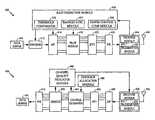
- FIG. 1is a functional block diagram of an embodiment of a wireless communication system configured to implement rate prediction and fractional reuse.
- FIG. 2is a coverage area diagram of an embodiment of a fractional reuse wireless communication system.
- FIG. 3is a time-frequency plot of an embodiment of a pilot channel carrier assignment.
- FIG. 4is a functional block diagram of embodiments of a transmitter and receiver.
- FIG. 5is a flowchart of an embodiment of a method of rate prediction in a fractional reuse communication system.
- a wireless communication system implementing Orthogonal Frequency Multiple Access (OFDMA) and fractional reusecan define a plurality of carrier sets and can constrain communications with a user terminal to operate within one or more of the carrier sets.
- OFDMAOrthogonal Frequency Multiple Access
- An OFDMA systemmay utilize fractional reuse.
- fractional reusea transmitter reserves part of the bandwidth for user terminals in handoff, thus allowing these user terminals to experience smaller interference levels. However, this may make the problem of rate prediction harder, because different reuse sets may see different channel qualities. Moreover, the user terminal may be blind to the reuse scheme.
- a frequency hopping techniquecan be incorporated.
- Each user terminalhas a hopping sequence assigned to it. This hopping sequence is constrained to hop within a reuse set. As a result, the user terminal can extrapolate the different reuse sets from the subcarriers assigned to it at any given time.
- the user terminalcan then report a channel quality information (CQI) for any desired reuse set, for example, the reuse set on which the user terminal is scheduled.
- CQIchannel quality information
- the user terminalcan determine the different reuse sets based on a predetermined hopping sequence, where a reuse set can be determined as a set of subcarriers that hops within the reuse set.
- the user terminalcan determine the subcarriers populating a reuse set using a variety of processes.
- the user terminalcan select a subcarrier at a given time instant.
- the user terminalcan then use the predetermined hopping sequence to determine where this subcarrier hops at the next time instant.
- the user terminalcan add this subcarrier assignment to the reuse set.
- the user terminalcan repeat the process until the set of identified subcarriers stops growing, that is, all new frequency hops are within the identified set of subcarriers.
- the identified set of subcarrierscan be a reuse set.
- the user terminalcan select a subcarrier that is in not within the set of subcarriers identified in the any of the reuse sets determined so far.
- the user terminalcan select a subcarrier distinct from a present subcarrier assignment.
- the user terminalcan then repeat the process to identify the remaining subcarriers in the reuse set.
- the user terminalcan determine any reuse set based on a subcarrier assignment and a predetermined hopping sequence.
- a user terminalcan determine its assigned reuse set in a low complexity manner by examining the subcarrier assignments over the past few time intervals and assume that they form the reuse set. This algorithm works well for the “static reuse” case, where each user terminal is assigned a single reuse set for a large amount of time.
- the user terminalmay, in an embodiment, determine a CQI based on a signal-to-noise ratio (SNR) of the user over a predetermined time period or a number of frames, such as a predetermined number of frames or a discrete time, e.g. 5 ms.
- the user terminalmay also quantize the CQI information as one or more CQI values.
- the CQI valueis quantized at steps of 2 dB of the SNR.
- the user terminalcan use pilot measurements to determine the channel strength while interference measurements can be based on data subcarriers.
- the user terminaltransmits the quantized or non-quantized CQI to the base station.
- the base stationcan modify this CQI to account for power control if pilot measurements do not take this into account.
- compensation for power controlis done in a linear manner, with the base station accounting for a +2 dB power control with a +2 dB change in the CQI.
- the base stationcompares this modified CQI with a set of thresholds to determine which packet format and corresponding rate is to be assigned to the user terminal.
- the user terminalperforms CQI determination based on interference estimation on the data subcarriers.
- the interference estimationcan be performed on subcarriers assigned to other user terminals, because the user might not be scheduled all the time.
- the user terminalcan determine the CQI for more than one reuse set, including a reuse set for which the user terminal is not assigned. In other embodiments, the user terminal can determine and report CQI for all possible reuse sets, the reuse set for which the user terminal was last scheduled, a predetermined group of reuse sets, or instructed reuse sets based upon communication with the base station.
- the user terminalcan measure the interference on a set of associated subcarriers within the reuse set using the same interference estimation algorithm used for data demodulation at the receiver.
- the interference measurement algorithmcan use blank pilots, i.e., dedicated symbols which the base station leaves blank.
- the user terminalcan also determine a measurement of channel strength using the FDM pilots.
- the user terminalcan determine SNR for the set of associated subcarriers.
- the user terminalcan get one SNR measurement for every set of associated subcarriers and for every hop. In this manner it can get several realizations of the SNR distribution that is seen over frequency and time. Using these realizations, it can compute the average value of the SNR that will be seen over the frame.
- the user terminalcan transmit this measurement back to the base station.
- a rate prediction algorithm in the base stationcan be configured to target the third transmission for termination so that there is some potential for early termination in case of a pessimistic CQI measurement, and also some protection against errors in case the CQI measurement is optimistic.
- the termination statisticsare computed based on FER curves for the third transmission.
- rate predictionwill target the second transmission.
- rate predictionwill go on to target the first transmission.
- the rate prediction algorithmcan be configured to initially target other transmissions for termination, such as the second or the first transmission based on delay or spectral efficiency requirements.
- a receiver in the base stationcan determine CQI values and report them to a transmitting user terminal.
- the RL rate prediction algorithmcan be configured very similar to the FL algorithm. If the channel estimation on the reverse link is poor, for example due to low bit rate or lack of diversity on the RL transmission, a long averaging filter can be employed in order to get a more accurate CQI.
- the only pilots signals availablemay be on a control channel, which gives the base station access to only a few, for example 2-4, subcarriers, which may or may not be within the reuse set of the user terminal, of the entire frequency band in a period equal to that used for the FL.
- the user terminalcan average the CQI values over a longer period in order to obtain an accurate measurement.
- the averaging periodcan be of the order of 100 ms, but can be some other period that can be determined based on system designs.
- the interference measurementas in the case of the FL, can be based on data subcarriers belonging to users in the same reuse set.
- the base stationhas knowledge of all the reuse sets, and can in fact determine an individual CQI for each reuse set.
- the averaging period of the CQImay create situations where the rate control algorithm is not be able to respond to the local channel fade. This is may not present issues since to some extent the changes in the rate may be limited by the channel assignment bandwidth.
- the reverse link power control algorithmgenerally maintains the control channel SNR around fixed value, at a rate which is faster than that of the rate prediction algorithm. As a result, the rate prediction algorithm should see an SNR that is almost static.
- the reverse link power control algorithmkeeps the SNR of the control channel approximately constant.
- the data power spectral density (psd)can be offset from the control channel psd by an amount that is controlled by the user terminal. This offset can be communicated to the base station through in-band signaling when the user terminal is scheduled, and can be used in the CQI computation. Even if the user terminal is not scheduled for a significant interval, this offset can be assumed to vary by a small enough amount that the rate prediction algorithm does not have to take into account errors in the offset and may utilize prior offset values. Alternatively, the rate prediction algorithm can take an additional backoff based on the amount of time lapsed since the user terminal was last scheduled, that is, since the value of the offset was last communicated.
- the algorithmproceeds as in the case of the FL.
- the CQI valueis compared with one or more predetermined thresholds for different packet formats, initially based on the third transmission. If the CQI is too high even for the least complex packet format at the third transmission, or if the packet has more stringent delay requirements, thresholds for the earlier transmissions may be used.
- a backoff control loopcan be the same as used in the FL.
- Rate predictioncan be performed at a slow rate relative to the rate of data transmission.
- rate prediction algorithmcould thus build a table mapping the value of the offset to a packet format. If such a table were available, however, then rate prediction could be performed either at the base station or at the access terminal.
- Another embodimentperforms rate prediction simply based on the observed termination statistics and the termination requirements demanded by the QoS. This embodiment could also be done at either the access terminal or the base station. Such an algorithm, would, however, be somewhat ad-hoc in nature and would have to be developed through simulations.
- FIG. 1is a functional block diagram of an embodiment of a wireless communication system 100 .
- the systemincludes one or more fixed elements that can be in communication with a user terminal 110 .
- the user terminal 110can be, for example, a wireless telephone configured to operate according to one or more communication standards.
- the user terminal 110can be a portable unit, a mobile unit, or, a stationary unit.
- the user terminal 110may also be referred to as a mobile unit, a mobile terminal, a mobile station, user equipment, a portable, a phone, and the like.
- FIG. 1it is understood that a typical wireless communication system 100 has the ability to communicate with multiple user terminals 110 .
- the user terminal 110typically communicates with one or more base stations 120 a or 120 b , here depicted as sectored cellular towers.
- a base stationmay be a fixed station used for communicating with the terminals and may also be referred to as, and include some or all the functionality of, an access point, a Node B, or some other terminology.
- the user terminal 110will typically communicate with the base station, for example 120 b , that provides the strongest signal strength at a receiver within the user terminal 110 .
- the one or more base stations 120 a - 120 bcan be configured to utilize fractional frequency reuse in which a fraction of the bandwidth for a base station, such as 120 a , is shared with a fraction of the bandwidth allocated to an adjacent base station, such as 120 b.
- Each of the base stations 120 a and 120 bcan be coupled to a Base Station Controller (BSC) 130 that routes the communication signals to and from the appropriate base stations 120 a and 120 b .
- the BSC 130may be coupled to a Mobile Switching Center (MSC) 140 that can be configured to operate as an interface between the user terminal 110 and a Public Switched Telephone Network (PSTN) 150 .
- the MSC 140can also be configured to operate as an interface between the user terminal 110 and a network 160 .
- the network 160can be, for example, a Local Area Network (LAN) or a Wide Area Network (WAN). In one embodiment, the network 160 includes the Internet. Therefore, the MSC 140 is coupled to the PSTN 150 and network 160 .
- the MSC 140can also be configured to coordinate inter-system handoffs with other communication systems (not shown).
- the wireless communication system 100can be configured as an OFDMA system with communications in both the forward link and reverse link utilizing OFDM communications.
- the term forward linkrefers to the communication link from the base stations 120 a or 120 b to the user terminal 110
- the term reverse linkrefers to the communication link from the user terminal 110 to the base stations 120 a or 120 b .
- Both the base stations 120 a and 120 b and the user terminal 110may allocate resources for channel and interference estimation.
- both the base stations 120 a and 120 b and the user terminal 110may broadcast pilot signals that are used be the corresponding receivers for channel and interference estimation.
- rate predictionis not limited to application in the forward link, but may be used in both the forward link as well as the reverse link, or may be implemented in one communication link exclusive of the other.
- the base stations 120 a and 120 bcan be configured to broadcast a pilot signal for purposes of channel and interference estimation.
- the pilot signalcan include a number of tones selected from the OFDM frequency set.
- the common pilot signalcan utilize uniformly spaced tones selected from the OFDM frequency set. The uniformly spaced configuration may be referred to as a comb pilot signal.
- the common pilot signalcan be formed from uniformly spaced carriers selected from the OFDM frequency set and dedicated pilot signals that are blanked.
- the base stations 120 a and 120 bcan also be configured to allocate a set of carriers from a reuse set to the user terminal 110 for communications.
- the set of carriers allocated to the user terminal 110can be fixed or can vary. If the set of carriers varies, the base station, for example 120 a , can periodically send an update of the allocated set of carriers to the user terminal 110 .
- the set of carriers assigned to a particular user terminal 110may vary according to a predetermined frequency hopping algorithm.
- the base station 120 aassigns a set of carriers to a user terminal 110
- the user terminal 110can determine the next set of carriers based on a predetermined frequency hopping algorithm.
- the predetermined frequency hopping algorithmcan be configured to ensure that the carrier set remains in the same reuse set that encompasses the previous carrier set.
- the user terminal 110can determine an estimate of the channel and interference based on the received pilot signal. Additionally, the user terminal 110 can determine an estimate of the signal quality of the received signal, such as by determining a received signal to noise ratio (SNR). The signal quality of the received signal can be quantified as a channel quality indicator (CQI) value, which can be determined, in part based on the estimated channel and interference.
- CQIchannel quality indicator
- the user terminal 110advantageously determines a channel and interference estimate corresponding to the reuse set with which it is associated.
- the user terminal 110reports the CQI value back to the base station, for example 120 a , and the base station 120 a can compare the CQI value against one or more predetermined thresholds to determine a data format and rate that is likely supported by the channel.
- the base station 120 acan determine a data format and rate targeting an initial transmission or a subsequent retransmission.
- HARQHybrid Automatic Repeat Request
- retransmissionsmay be transmitted at lower rates corresponding lower encoding rates.
- the HARQ implementationcan be configured to provide a maximum number or retransmissions, and each of the retransmissions can occur at a lower rate.
- the HARQ processcan be configured to transmit some of the retransmissions at the same rate.
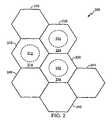
- FIG. 2is a coverage area diagram 200 of an embodiment of a cellular wireless communication system implementing fractional frequency reuse.
- the wireless communication systemcan be, for example, the wireless communication system 100 shown in FIG. 1 .
- the coverage area diagram 200shows a number of coverage areas 210 , 220 , 230 , 240 , 250 , 260 , and 270 arranged to provide an overall coverage.
- Each of the coverage areas, for example 210can have a base station positioned in the center.
- a wireless communication systemis not limited to the number of coverage areas shown in FIG. 2 , nor is the coverage area limited to the pattern shown in FIG. 2 .
- the coverage areas, for example 210can be configured to support OFDM communications using a predetermined number of carriers.
- One or more of the coverage areas, for example 210can implement multiple reuse sets, and a plurality of the coverage areas, for example 210 , 220 , and 230 , can implement partial frequency reuse.
- a first coverage area 210is shown as arranged as an outer hexagonal shape encompassing an inner circle.
- the first coverage area 210can implement partial frequency reuse and multiple reuse sets.
- An inner coverage area 212can implement a stable reuse set allocated to user terminals having a low probability of initiating a handoff.
- An outer coverage area 214outside of the inner coverage area 212 , can implement a handoff reuse set that can be allocated to user terminals that have a higher probability of initiating a handoff.
- the stable reuse setcan use a first set of carriers from the OFDM frequency set and the handoff reuse set can use a second distinct set of carriers from the OFDM frequency set. Additionally, the second set of carriers in the handoff reuse set can be shared with a reuse set of an adjacent coverage area, such as 220 or 230 .
- a user terminal in the first coverage area 210can initially be allocated a set of carriers within the stable reuse set.
- the base stationcan, for example, communicate the assigned carriers in the stable reuse set to the user terminal.
- the user terminalcan then determine subsequent carrier assignments within the stable reuse set based in part on a frequency hopping algorithm.
- the user terminaldetermines channel and interference estimates, and determines a CQI value based on the stable reuse set.
- the base stationmay allocate a set of carriers from the handoff reuse set to the user terminal.
- the base stationcan transmit a control message to the user terminal to indicate that the user terminal should hop to the handoff reuse set.
- the user terminalcan then determine subsequent carrier assignments within the handoff reuse set based in part on a frequency hopping algorithm, which can be the same or different from the frequency hopping algorithm used to determine carrier sets in the stable reuse set.
- the user terminaldetermines channel and interference estimates, and determines a CQI value based on the handoff reuse set.
- Such a reuse set configurationmay be advantageous because fewer users can be assigned to the handoff reuse set, allowing the users in the handoff reuse set to see smaller interference levels.
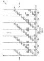
- FIG. 3is a time-frequency diagram 300 of an example of a spectrum of an OFDMA communication system using a comb pilot signal with a dedicated pilot signal.
- the time-frequency diagram 300illustrates an example of an OFDMA system in which carrier blocks 310 a - 310 f are assigned to each user in the system.
- a number of common pilot signals, designated by ‘P’ e.g. 320are present in each time epoch, but do not necessarily appear within each carrier block 310 a - 310 f .
- the common pilot signals, e.g. 320are not assigned to the same carriers at each time epoch, but instead follow a predetermined algorithm.
- a number of dedicated pilot signals 330can be present within each carrier block 310 a - 310 f but may not be present in each time epoch.
- Each receivercan determine channel and interference estimates based in part on all of the common 320 and dedicated 330 pilot signals.
- a first set of carrier blocksfor example 310 a - 310 d can be assigned to the stable reuse set and a second set of carrier blocks, for example 310 e - 310 g , can be assigned to the handoff reuse set.
- the handoff reuse setcan also be shared with a second base station. Because the different reuse sets have different interference levels, the user terminal can be configured to estimate the channel and interference and determine the CQI value based on the assigned reuse set. The user terminal can then report the CQI value back to the base station, for example, using a control channel or an overhead channel.
- FIG. 4is a functional block diagram of an embodiment of a data source 400 and receiver 404 that can be implemented with a wireless communication system such as the wireless communication system of FIG. 1 .
- the data source 400can be, for example, a transmitter portion within a base station or a transmitter portion within a user terminal.
- the embodiment of the receiver 404similarly can be implemented, for example, in one or both of the base station and user terminal shown in the wireless communication system 100 of FIG. 1 .
- the data source 400is implemented in a base station of a wireless communication system configured for OFDMA communications with fractional reuse and HARQ.
- the data source 400is configured to transmit one or more OFDMA signals to one or more user terminals.
- the data source 400includes a data buffer 410 configured to store data destined for one or more receivers.
- the datacan be, for example, raw unencoded data or encoded data.
- the data stored in the data buffer 410is unencoded, and is coupled to the encoder 412 where it is encoded according to the rate determined by the rate prediction module 430 .
- the encoder 412can include encoding for error detection and Forward Error Correction (FEC).
- FECForward Error Correction
- the encoded datacan be encoded according to one or more encoding algorithms.
- Each of the encoding algorithms and resultant coding ratescan be associated with a particular data format of a multiple format HARQ system.
- the encodingcan include, but is not limited to, convolutional coding, block coding, interleaving, direct sequence spreading, cyclic redundancy coding, and the like, or some other coding.
- the rate prediction module 430performs selection of the data format and associated coding.
- the encoded data to be transmittedis coupled to a serial to parallel converter 414 that is configured to convert a serial data stream from the encoder 412 to a plurality of data streams in parallel.
- the number of carriers allocated to any particular user terminalmay be a subset of all available carriers. Therefore, the data destined for a particular user terminals is converted to those parallel data streams corresponding to the data carriers allocated to that user terminal.
- the output of the serial to parallel converter 414is coupled to a pilot module 420 that is configured to allocate the common pilot channels to the common pilot and to allocate the dedicated pilot signals.
- the pilot module 420can be configured to modulate each of the carriers of the OFDMA system with a corresponding data or pilot signal.
- the output of the pilot module 420is coupled to an Inverse Fast Fourier Transform (IFFT) module 422 .
- the IFFT module 422is configured to transform the OFDMA carriers to corresponding time domain symbols.
- FFTFast Fourier Transform
- DFTDiscrete Fourier Transform
- the output of the IFFT module 422is coupled to a parallel to serial converter 424 that is configured to convert the parallel time domain symbols to a serial stream.
- the serial OFDMA symbol streamis coupled from the parallel to serial converter 424 to a transceiver 440 .
- the transceiver 440is a base station transceiver configured to transmit the forward link signals and receive reverse link signals.
- the transceiver 440includes a transmitter module 444 that is configured to convert the serial symbol stream to an analog signal at an appropriate frequency for broadcast to user terminals via an antenna 446 .
- the transceiver 440can also include a receiver module 442 that is coupled to the antenna 446 and is configured to receive the signals transmitted by one or more remote user terminals.
- a rate prediction module 430is configured to determine the proper data format and corresponding encoding that can be supported over a communications channel linking the data source 400 , such as a base station, to a receiver 404 , such as a user terminal.
- the rate prediction module 430receives one or more CQI values from the receiver 404 , via a reverse link channel, and determines the data rate and associated encoding based on the CQI values.
- the rate prediction module 430can include a threshold comparator 432 , backoff control module 434 , and power control compensation module 436 that each process one or more of the received CQI values to assist in determining the appropriate rate.
- the OFDMA wireless communication systemtypically uses power control on the forward link.
- the use of power controlcan complicate the rate-prediction determination because the user terminal typically reports a CQI value that is based on the pilot power or maybe the current data power.
- the CQI value determined by the user terminal in a future frame of transmissionwill be substantially different if the transmit power changes.
- the user terminalmay report an effective SNR which may be a non-linear function of the transmit power.
- the base stationcan use the power control compensation module 436 to modify the CQI value to approximately account for transmit power variations.
- the power control compensation module 436performs a linear approximation relative to the power control value. If the transmit power changes up or down by a certain dB value, then the power control compensation module 436 modifies the reported CQI value by the same dB value.
- the linear approximation implemented by the power control compensation module 436is an approximation, and such, will likely result in a residual error which can be compensated.
- This errorcan be quite significant for certain operating conditions. Another thing to note is that this error can be one sided, i.e., it is positive when the transmit power increases and negative when the transmit power decreases.
- the CQI valuecan be further biased, or compensated, to further reduce the mean error closer to zero.
- the backoff control module 434can be configured to provide the additional compensation by subtracting a backoff value from the CQI value.
- the backoff control module 434can maintain a variable in dB, ⁇ , referred to as backoff for every user terminal. Every time the user terminal reports a CQI value, the power control compensation module 436 adjusts the value to take transmit power variations into account. The backoff control module 434 then subtracts the value ⁇ from the modified CQI value.
- the value of ⁇needs to be initialized to an appropriate value, and can also have defined minimum and maximum values. Apart from this, the backoff control module 434 can update the backoff value to satisfy the constraint that the packet error rate should be less than a predetermined threshold, such as 1%.
- the backoff control module 434can increase the value of ⁇ by a predetermined increment, for example 0.25 dB, every time a packet is received in error.
- a packet errormay refer to an unsuccessful last transmission in a HARQ system, not just an unsuccessful targeted transmission.
- the backoff control module 434can be configured to reduce the backoff value by a predetermined amount, for example 0.25*0.01 dB, every time a packet is decoded correctly.
- the backoff control module 434may not have an upper bound on ⁇ since it is used to keep the packet error rate under 1%. However, the backoff control module 434 may implement a lower bound. A lower bound may be necessary because otherwise the rate prediction module 430 may drive to the last transmission of the highest feasible packet format, which might be a lower rate than the one that was targeted. As an initial value, the backoff control module 434 can implement a lower bound at 0 dB. The initial value is not very important except to avoid initial errors, and can be arbitrarily set to approximately 1.5 dB.
- the threshold comparator 432can be configured to compare the processed CQI value against a number of predetermined thresholds, with each threshold corresponding to a particular packet format and coding likely supported by the communication link. As noted before, in a HARQ system, the rate prediction module can target a rate that is subsequent to the first transmission.
- the receiver 404can be, for example, part of a user terminal 110 or base station 120 a or 120 b shown in FIG. 1 .
- the following discussiondescribes a receiver 404 implemented within a user terminal.
- the receiver 404can include an antenna 456 coupled to a transceiver 450 configured to communicate over a wireless channel with the data source 400 .
- the transceiver 450can include a receiver module 452 configured to receive the wireless signals, via the antenna 456 , and generate a serial baseband symbol stream.
- the output of the receiver module 450 of the transceiver 450is coupled to a serial to parallel converter 460 configured to convert the serial symbol stream to a plurality of parallel streams corresponding to the number of carriers in the OFDMA system.
- the output of the serial to parallel converter 460is coupled to a Fast Fourier Transform (FFT) module 462 .
- the FFT module 462is configured to transform the time domain symbols to the frequency domain counterpart.
- the output of the FFT module 462is coupled to a channel estimator 464 that is configure to determine a channel and interference estimate based in part on the common pilot signals and any dedicated pilot signals.
- a carrier allocation module 480can determine the carriers assigned to the data, the carriers assigned to the common pilot signals, and the carriers, if any, assigned to the dedicated pilot signals.
- the carrier allocation module 480can, for example, implement a frequency hopping algorithm to determine the current carrier assignment based on a past assignment.
- the carrier allocation module 480can be configured to determine a carrier assignment for a particular reuse set.
- the carrier allocation module 480is coupled to the channel estimator 464 and informs the channel estimator 464 of the carrier assignment.
- the channel estimator 464determines a channel and interference estimate based in part on the common pilot signals the dedicated pilot signals, if any.
- the channel estimator 464can determine an estimate using a least squares method, a maximum likelihood estimate, a combination of least squares and maximum likelihood estimate, and the like, or some other process of channel and interference estimation.
- the output of the channel estimator 464 including the frequency domain transform of the received symbols and the channel and interference estimateis coupled to a demodulator 470 .
- the carrier allocation module 470can also inform the demodulator 470 of the carrier frequencies allocated to data transmission.
- the demodulator 470is configured to demodulate the received data carriers based in part on the channel and interference estimate. In some instances, the demodulator 470 may be unable to demodulate the received signals. As noted earlier, the demodulator 470 may be unsuccessful because the channel quality is inadequate and cannot support the transmitted rate of the data, or because degradation attributable to inadequate channel and interference estimation is sufficiently severe to result in decoding error.
- the demodulator 470can generate an indication of the inability to demodulate the received signals.
- the demodulator 470can, for example, inform the carrier allocation module 480 such that the carrier allocation module 480 can expect a dedicated pilot signal in subsequent transmission.
- the demodulator 470can also provide an unsuccessful demodulation indication to the transmitter module 454 in the transceiver 450 for transmission back to the data source 400 .
- the demodulator 470can be configured to couple the demodulated data to a parallel to serial converter 472 that is configured to convert the parallel demodulated data to a serial data stream.
- the output of the parallel to serial converter 472is coupled to a data buffer 474 for further processing.
- a channel quality indicator (CQI) module 490can also be coupled to the channel estimator 464 and demodulator 470 and can use the values of pilot power, channel estimate, and interference estimate to determine a value of the CQI.
- the CQI valueis based in part on the SNR.
- the CQI module 490couples the CQI value to the transmitter module 454 , which can be configured to transmit the value to the data source 400 using, for example, an overhead channel, control channel, or traffic channel.
- the CQI module 490can determine a CQI value for one or more reuse sets. For example, the CQI module 490 can determine a CQI value for the present reuse set based on the present subcarrier assignment and a predetermined frequency hopping algorithm. The CQI module 490 may also determine a CQI value for a reuse set distinct from the reuse set assigned to the receiver 404 .
- FIG. 5is a flowchart of an embodiment of a method 500 of rate prediction in a fractional reuse OFDMA system.
- the method 500can be performed, for example, by the base station of the wireless communication system of FIG. 1 to configure the forward link transmissions.
- the method 500can be performed by a user terminal of the wireless communication system of FIG. 1 to configure reverse link transmissions.
- the following descriptionassumes a base station performs the method 500 .
- the method 500begins at block 502 when the base station initially determines a subcarrier assignment within a reuse set of the fractional reuse communication system.
- the base stationcan, for example, determine a subcarrier assignment in a stable reuse set for a user terminal having a low probability of handoff, or within a predetermined radius of the base station.
- the base stationmay determine a subcarrier assignment in a handoff reuse set for a user terminal that has a high probability of handoff.
- the base stationcan transmit the subcarrier assignment to the user terminal.
- the base stationneed not transmit the subcarrier assignment if the user terminal or mobile station can determine the subcarrier assignment based in part on a frequency hopping algorithm and a prior subcarrier assignment.
- the base stationcan transmit data to the user terminal on the assigned subcarriers.
- the base stationproceeds to block 510 and transmits a pilot signal.
- the pilot signalcan include a common pilot signal and a dedicated pilot signal.
- the user terminalcan receive the pilot signal and can determine, based on the subcarrier assignment and the pilot signals, a CQI value. The user terminal can transmit this CQI value to the base station.
- the base stationproceeds to block 520 and receives the CQI value based in part on the subcarrier assignment and the pilot signal.
- the user terminalcan determine and transmit a CQI value that is based on the current subcarrier assignment.
- the user terminalcan determine a CQI value based on a future subcarrier assignment that can be determined using the present subcarrier assignment and a frequency hopping algorithm.
- the base stationthen proceeds to block 530 and determines a transmission format based in part on the channel quality indicator.
- the base stationcan process the received CQI value using, for example, a power control compensation module, a backoff control module, and the like, or some other signal processing module.
- the base stationcan average a predetermined number of CQI values.
- the base stationcan determine the transmission format, for example, by comparing the CQI value against a number of predetermined thresholds. The base station then proceeds to block 540 and controls a code rate based in part on the transmission format.
- the base stationcan, for example, control an encoder to encode data according to the code rate determined by the rate prediction module.
- the base stationcan then transmit the encoded data to the user terminal.
- DSPdigital signal processor
- RISCReduced Instruction Set Computer
- ASICapplication specific integrated circuit
- FPGAfield programmable gate array
- a general purpose processormay be a microprocessor, but in the alternative, the processor may be any processor, controller, microcontroller, or state machine.
- a processormay also be implemented as a combination of computing devices, for example, a combination of a DSP and a microprocessor, a plurality of microprocessors, one or more microprocessors in conjunction with a DSP core, or any other such configuration.
- a software modulemay reside in RAM memory, flash memory, non-volatile memory, ROM memory, EPROM memory, EEPROM memory, registers, hard disk, a removable disk, a CD-ROM, or any other form of storage medium known in the art.
- An exemplary storage mediumis coupled to the processor such the processor can read information from, and write information to, the storage medium.
- the storage mediummay be integral to the processor.
- the various methodsmay be performed in the order shown in the embodiments or may be performed using a modified order of steps. Additionally, one or more process or method steps may be omitted or one or more process or method steps may be added to the methods and processes. An additional step, block, or action may be added in the beginning, end, or intervening existing elements of the methods and processes.
Landscapes
- Engineering & Computer Science (AREA)
- Signal Processing (AREA)
- Computer Networks & Wireless Communication (AREA)
- Quality & Reliability (AREA)
- Mobile Radio Communication Systems (AREA)
- Liquid Crystal Substances (AREA)
- Gyroscopes (AREA)
- Amplifiers (AREA)
Abstract
Description
Claims (47)
Priority Applications (1)
| Application Number | Priority Date | Filing Date | Title |
|---|---|---|---|
| US11/168,904US9294218B2 (en) | 2004-07-16 | 2005-06-28 | Rate prediction in fractional reuse systems |
Applications Claiming Priority (2)
| Application Number | Priority Date | Filing Date | Title |
|---|---|---|---|
| US58862904P | 2004-07-16 | 2004-07-16 | |
| US11/168,904US9294218B2 (en) | 2004-07-16 | 2005-06-28 | Rate prediction in fractional reuse systems |
Publications (2)
| Publication Number | Publication Date |
|---|---|
| US20060014542A1 US20060014542A1 (en) | 2006-01-19 |
| US9294218B2true US9294218B2 (en) | 2016-03-22 |
Family
ID=35058834
Family Applications (1)
| Application Number | Title | Priority Date | Filing Date |
|---|---|---|---|
| US11/168,904Expired - Fee RelatedUS9294218B2 (en) | 2004-07-16 | 2005-06-28 | Rate prediction in fractional reuse systems |
Country Status (11)
| Country | Link |
|---|---|
| US (1) | US9294218B2 (en) |
| EP (2) | EP2256975B1 (en) |
| JP (3) | JP2008507215A (en) |
| KR (1) | KR100885137B1 (en) |
| CN (1) | CN101019362B (en) |
| AT (1) | ATE488062T1 (en) |
| CA (1) | CA2574066C (en) |
| DE (1) | DE602005024692D1 (en) |
| ES (2) | ES2356170T3 (en) |
| TW (1) | TWI389501B (en) |
| WO (1) | WO2006020032A1 (en) |
Cited By (1)
| Publication number | Priority date | Publication date | Assignee | Title |
|---|---|---|---|---|
| CN107979454A (en)* | 2017-11-22 | 2018-05-01 | 华南理工大学 | A kind of OFDMA distributed modes downlink comb spectrum rapid extracting method |
Families Citing this family (78)
| Publication number | Priority date | Publication date | Assignee | Title |
|---|---|---|---|---|
| US5754961A (en) | 1994-06-20 | 1998-05-19 | Kabushiki Kaisha Toshiba | Radio communication system including SDL having transmission rate of relatively high speed |
| JP4734116B2 (en) | 2003-08-06 | 2011-07-27 | パナソニック株式会社 | Wireless communication apparatus and reception quality reporting method |
| DE102004028703A1 (en)* | 2004-06-14 | 2005-12-29 | Siemens Ag | Method for allocating transmission capacities in a signal transmission, base station and mobile terminal |
| US20060092873A1 (en)* | 2004-10-29 | 2006-05-04 | Telefonaktiebolaget Lm Ericsson ( Publ) | Method for adaptive interleaving in a wireless communication system with feedback |
| US8233907B1 (en) | 2004-11-03 | 2012-07-31 | At&T Mobility Ii Llc | System and method for constructing a carrier to interference matrix based on subscriber calls |
| KR100703442B1 (en)* | 2004-11-12 | 2007-04-03 | 삼성전자주식회사 | Handover Method and System in Broadband Wireless Access Communication System |
| KR100617835B1 (en)* | 2005-01-05 | 2006-08-28 | 삼성전자주식회사 | Apparatus and method for transmitting/receiving a channel quality information in a communication system |
| US7742444B2 (en)* | 2005-03-15 | 2010-06-22 | Qualcomm Incorporated | Multiple other sector information combining for power control in a wireless communication system |
| US8064327B2 (en)* | 2005-05-04 | 2011-11-22 | Samsung Electronics Co., Ltd. | Adaptive data multiplexing method in OFDMA system and transmission/reception apparatus thereof |
| US8965440B2 (en)* | 2005-05-31 | 2015-02-24 | Alcatel Lucent | Method of estimating a current channel condition in a wireless communications network |
| US8750908B2 (en)* | 2005-06-16 | 2014-06-10 | Qualcomm Incorporated | Quick paging channel with reduced probability of missed page |
| US9055552B2 (en)* | 2005-06-16 | 2015-06-09 | Qualcomm Incorporated | Quick paging channel with reduced probability of missed page |
| EP1734665B1 (en) | 2005-06-17 | 2011-08-10 | Fujitsu Limited | Multi-hop communication system |
| EP1734667B1 (en) | 2005-06-17 | 2011-08-10 | Fujitsu Limited | Multi-hop communication system |
| EP2144467B1 (en) | 2005-06-17 | 2011-11-23 | Fujitsu Limited | Systems and methods for power control in multi-hop communication system |
| EP1734666A1 (en) | 2005-06-17 | 2006-12-20 | Fujitsu Limited | Resource management in multi-hop communication system |
| KR100747600B1 (en)* | 2005-08-19 | 2007-08-08 | 한국전자통신연구원 | Dynamic Resource Allocation Method Based on Frequency Reuse Rate Division Method for Orthogonal Frequency Division Multiple Access System and Frame Transmission Method Therefor |
| WO2007021139A1 (en)* | 2005-08-19 | 2007-02-22 | Electronics And Telecommunications Research Institute | Dynamic resource allocation method based on frequency reuse partitioning for ofdma/fdd system, and frame transmission method therefor |
| US20090207790A1 (en)* | 2005-10-27 | 2009-08-20 | Qualcomm Incorporated | Method and apparatus for settingtuneawaystatus in an open state in wireless communication system |
| US20100150106A1 (en)* | 2005-10-27 | 2010-06-17 | Qualcomm Incorporated | Method and apparatus for managing assignment during handoff in wireless communication systems |
| US20070147226A1 (en)* | 2005-10-27 | 2007-06-28 | Aamod Khandekar | Method and apparatus for achieving flexible bandwidth using variable guard bands |
| US8175021B2 (en)* | 2005-11-04 | 2012-05-08 | Texas Instruments Incorporated | Method for transmission of unicast control in broadcast/multicast transmission time intervals |
| US8811369B2 (en)* | 2006-01-11 | 2014-08-19 | Qualcomm Incorporated | Methods and apparatus for supporting multiple communications modes of operation |
| ATE526801T1 (en) | 2006-01-11 | 2011-10-15 | Qualcomm Inc | COMMUNICATION METHOD AND APPARATUS FOR SENDING PRIORITY INFORMATION VIA BEACON SIGNALS |
| US20070177501A1 (en)* | 2006-01-31 | 2007-08-02 | Texas Instruments Incorporated | Signaling Requirements to Support Interference Coordination in OFDMA Based Systems |
| US7440412B2 (en)* | 2006-03-13 | 2008-10-21 | Tzero Technologies, Inc. | Link quality prediction |
| EP1999982B1 (en)* | 2006-03-20 | 2018-08-29 | BlackBerry Limited | Method&system for fractional frequency reuse in a wireless communication network |
| DE602006003859D1 (en)* | 2006-03-20 | 2009-01-08 | Alcatel Lucent | A method of partitioning user terminals into subcarriers in a multi-cell or multi-sector FDM communication network, a base station and a network therefor |
| EP1863209A1 (en)* | 2006-06-02 | 2007-12-05 | Alcatel Lucent | Channel quality reporting in an orthogonal frequency division multiplexing system |
| US7933606B2 (en)* | 2006-06-30 | 2011-04-26 | Nokia Corporation | Multi-level control for measurement reports |
| EP1895806B1 (en) | 2006-08-30 | 2016-09-28 | Vodafone Holding GmbH | Resource distribution in wireless communication systems |
| US8611259B2 (en)* | 2006-09-08 | 2013-12-17 | Samsung Electronics Co., Ltd. | Method and system for providing channel state information feedback in a wireless communication system |
| US8254927B2 (en)* | 2006-09-11 | 2012-08-28 | Qualcomm Incorporated | SFN and signaling mechanisms for softer handoff groups |
| JP5015255B2 (en)* | 2006-09-29 | 2012-08-29 | インテル コーポレイション | Channel quality evaluation method and corresponding system in OFDM (A) communication |
| GB0619454D0 (en) | 2006-10-02 | 2006-11-08 | Fujitsu Ltd | Communication systems |
| CA2663976A1 (en) | 2006-10-24 | 2008-05-02 | Qualcomm Incorporated | Enabling resource partitioning for wireless communication systems |
| EP2605600A1 (en) | 2006-10-31 | 2013-06-19 | Qualcomm Incorporated | Inter-cell power control in the presence of fractional frequency reuse |
| GB2443464A (en) | 2006-11-06 | 2008-05-07 | Fujitsu Ltd | Signalling in a multi-hop communication systems |
| JP5156334B2 (en)* | 2006-12-04 | 2013-03-06 | 株式会社エヌ・ティ・ティ・ドコモ | Wireless communication apparatus and wireless communication method |
| US8483038B2 (en) | 2006-12-04 | 2013-07-09 | Ntt Docomo, Inc. | Radio communication apparatus and radio communication method |
| KR101401617B1 (en) | 2007-02-16 | 2014-06-03 | 삼성전자주식회사 | OFDM transmitting and receiving system and methods thereof |
| GB2447883A (en) | 2007-03-02 | 2008-10-01 | Fujitsu Ltd | Bandwidth allocation in multi-hop wireless communication systems |
| GB2447635A (en)* | 2007-03-19 | 2008-09-24 | Fujitsu Ltd | Scheduling qos communications between nodes within a predetermined time unit in wimax systems |
| FI20075223A0 (en)* | 2007-04-02 | 2007-04-02 | Nokia Corp | Improved communication link adaptation method improved link adaptation method |
| KR101454027B1 (en)* | 2007-08-10 | 2014-10-24 | 한국전자통신연구원 | Time Division Multiplexing Communication System and Method Having Parallel Structure |
| US7827270B2 (en)* | 2007-10-31 | 2010-11-02 | Cisco Technology, Inc. | Mobility service clustering using network service segments |
| US9326253B2 (en) | 2007-11-15 | 2016-04-26 | Qualcomm Incorporated | Wireless communication channel blanking |
| US8798665B2 (en) | 2007-11-15 | 2014-08-05 | Qualcomm Incorporated | Beacon-based control channels |
| US8761032B2 (en) | 2007-11-16 | 2014-06-24 | Qualcomm Incorporated | Random reuse based control channels |
| US7649839B2 (en)* | 2007-11-21 | 2010-01-19 | Motorola, Inc. | Method and device for managing data rate in a communication system |
| JP5088149B2 (en)* | 2008-01-17 | 2012-12-05 | 富士通株式会社 | Scheduling method and radio base station |
| US9009573B2 (en) | 2008-02-01 | 2015-04-14 | Qualcomm Incorporated | Method and apparatus for facilitating concatenated codes for beacon channels |
| JP5169689B2 (en)* | 2008-02-14 | 2013-03-27 | 富士通株式会社 | Communication device |
| US8306473B2 (en)* | 2008-02-15 | 2012-11-06 | Qualcomm Incorporated | Methods and apparatus for using multiple antennas having different polarization |
| KR101480550B1 (en)* | 2008-03-26 | 2015-01-20 | 엘지전자 주식회사 | Method for Performing Intercell Interference Coordination |
| US8675537B2 (en) | 2008-04-07 | 2014-03-18 | Qualcomm Incorporated | Method and apparatus for using MBSFN subframes to send unicast information |
| US9107239B2 (en) | 2008-04-07 | 2015-08-11 | Qualcomm Incorporated | Systems and methods to define control channels using reserved resource blocks |
| US8595501B2 (en)* | 2008-05-09 | 2013-11-26 | Qualcomm Incorporated | Network helper for authentication between a token and verifiers |
| KR101433847B1 (en) | 2008-05-28 | 2014-09-23 | 삼성전자주식회사 | Apparatus and method for burst scheduling in a broadband wireless communication system |
| WO2010018643A1 (en)* | 2008-08-12 | 2010-02-18 | 株式会社日立コミュニケーションテクノロジー | Radio communication system, radio communication device, and radio resource management method |
| WO2010024536A2 (en)* | 2008-08-27 | 2010-03-04 | 엘지전자 주식회사 | Apparatus for transmitting a signal in a wireless communication system and method for same |
| WO2010044621A2 (en)* | 2008-10-15 | 2010-04-22 | 엘지전자주식회사 | Method and apparatus for transmitting mbs data in wireless communication system using fractional frequency reuse |
| US8654834B2 (en) | 2009-01-06 | 2014-02-18 | Electronics And Telecommunications Research Institute | Method for tuning coding rate and applying unequal error protection for adaptive video transmission, and video transmission/reception apparatus using the method |
| US9084119B2 (en)* | 2009-01-07 | 2015-07-14 | Qualcomm Incorporated | Carrier reuse in a multicarrier wireless communication environment |
| US8817769B2 (en)* | 2009-01-26 | 2014-08-26 | Qualcomm Incorporated | Power decision pilot for wireless communication |
| CN101795148B (en)* | 2009-02-03 | 2014-07-16 | 中兴通讯股份有限公司 | Mapping method and device based on channel quality indication calculation pilot frequency |
| WO2010107267A2 (en)* | 2009-03-18 | 2010-09-23 | 한국전자통신연구원 | System for transmitting reference signal with information on state of channel |
| US20110038356A1 (en)* | 2009-08-13 | 2011-02-17 | Yuval Bachrach | VBR interference mitigation in an mmwave network |
| US8599768B2 (en)* | 2009-08-24 | 2013-12-03 | Intel Corporation | Distributing group size indications to mobile stations |
| KR101752416B1 (en)* | 2009-08-28 | 2017-06-29 | 엘지전자 주식회사 | A method for transmitting signal with fractional frequency reuse |
| IL202000A0 (en)* | 2009-11-09 | 2010-11-30 | Alvarion Ltd | Fractional frequency reuse deployment method for wireless system |
| CN102291731A (en)* | 2010-06-18 | 2011-12-21 | 电信科学技术研究院 | Measurement method applied to layered network and device thereof |
| US9398602B2 (en)* | 2010-09-22 | 2016-07-19 | Qualcomm Incorporated | Multi-radio coexistence |
| CN102958170B (en)* | 2011-08-30 | 2015-04-29 | 华为技术有限公司 | Up-link interference coordination method and base station |
| JP5479566B2 (en)* | 2012-12-12 | 2014-04-23 | 京セラ株式会社 | Wireless terminal and wireless communication method |
| EP2852238A1 (en) | 2013-09-19 | 2015-03-25 | NTT DoCoMo, Inc. | Signaling and interference estimation for dynamic fractional reuse |
| DE102014214923A1 (en) | 2014-07-30 | 2016-02-25 | Rohde & Schwarz Gmbh & Co. Kg | Method and device for determining an estimate of a noise power |
| CN113595698B (en)* | 2020-04-30 | 2023-06-02 | 华为技术有限公司 | Method for adjusting channel quality index CQI and terminal equipment |
Citations (30)
| Publication number | Priority date | Publication date | Assignee | Title |
|---|---|---|---|---|
| WO1996002979A2 (en) | 1994-07-15 | 1996-02-01 | Telefonaktiebolaget Lm Ericsson | Channel hopping in a radio communications system |
| GB2318252A (en) | 1996-10-09 | 1998-04-15 | Motorola Ltd | Channel Allocation in a Cellular Radio Network |
| US5991636A (en)* | 1996-08-21 | 1999-11-23 | Electronics And Telecommunications Research Institute | Adaptive power control method for a CDMA mobile radio telephone system |
| US6137787A (en) | 1997-04-03 | 2000-10-24 | Chawla; Kapil K. | Method and apparatus for resource assignment in a wireless communication system |
| US6256729B1 (en) | 1998-01-09 | 2001-07-03 | Sun Microsystems, Inc. | Method and apparatus for resolving multiple branches |
| JP2001274764A (en) | 2000-03-28 | 2001-10-05 | Matsushita Electric Ind Co Ltd | Digital signal transmitter |
| JP2001359152A (en) | 2000-06-14 | 2001-12-26 | Sony Corp | Radio communication system and radio base station device and radio mobile station device and radio zone assigning method and radio communication method |
| WO2002049305A2 (en) | 2000-12-15 | 2002-06-20 | Broadstorm Telecommunications, Inc. | Ofdma with adaptive subcarrier-cluster configuration and selective loading |
| WO2002058300A1 (en) | 2001-01-19 | 2002-07-25 | Broadstorm Telecommunications, Inc. | Multi-carrier communication with time division multiplexing and carrier-selective loading |
| US20020105925A1 (en)* | 2001-01-16 | 2002-08-08 | Shoemake Matthew B. | Jointly controlling transmission rate and power in a communications system |
| US20020136268A1 (en)* | 2001-01-25 | 2002-09-26 | Hongbing Gan | Approach for selecting communications channels based on performance |
| US6526279B1 (en)* | 1999-08-11 | 2003-02-25 | Ericsson Inc. | Communication system with a mobile terminal supporting mobile assisted signal strength measurements for a plurality of networks and methods for operating the same |
| US20030060209A1 (en)* | 2001-09-27 | 2003-03-27 | Bruin Peter De | Total radio network solution for GSM/EDGE |
| US6591108B1 (en)* | 2000-03-06 | 2003-07-08 | Lucent Technologies Inc. | Apparatus and method to reduce the reuse factor for adaptive-dynamic channel assignment systems |
| US6687239B1 (en) | 2000-05-08 | 2004-02-03 | Vtech Telecommunications, Ltd | Method for dynamic channel allocation in a frequency hopping radio system |
| JP2004129241A (en) | 2002-09-30 | 2004-04-22 | Lucent Technol Inc | Method of electric power allocation and speed control in ofdma system |
| US20040097238A1 (en)* | 2002-11-07 | 2004-05-20 | Samsung Electronics Co., Ltd. | Frequency reuse method in an orthogonal frequency division multiplex mobile communication system |
| WO2004045228A1 (en) | 2002-11-07 | 2004-05-27 | Broadstorm Telecommunications, Inc. | Method and apparatus for adaptive carrier allocation and power control in multi-carrier communication systems |
| JP2004173017A (en) | 2002-11-20 | 2004-06-17 | Matsushita Electric Ind Co Ltd | Base station apparatus and retransmission packet transmission power control method |
| JP2004172981A (en) | 2002-11-20 | 2004-06-17 | Matsushita Electric Ind Co Ltd | Wireless transmission device and wireless transmission method |
| US6792276B1 (en)* | 1999-07-13 | 2004-09-14 | Telefonaktiebolaget Lm Ericsson (Publ) | Hot spot with tailored range for extra frequency to minimize interference |
| US20050025040A1 (en)* | 2003-07-29 | 2005-02-03 | Nokia Corporation | Method and apparatus providing adaptive learning in an orthogonal frequency division multiplex communication system |
| JP2005080286A (en) | 2003-09-02 | 2005-03-24 | Korea Electronics Telecommun | Forward channel configuration method and forward channel allocation method in OFDMA / FDD based mobile communication system |
| US6907228B1 (en)* | 2001-08-21 | 2005-06-14 | Nortel Networks Limited | Allocating carrier frequencies for communicating beacon control signaling |
| US20050169229A1 (en)* | 2003-12-23 | 2005-08-04 | Samsung Electronics Co., Ltd. | Apparatus and method for allocating subchannels adaptively according to frequency reuse rates in an orthogonal frequency division multiple access system |
| US6940827B2 (en)* | 2001-03-09 | 2005-09-06 | Adaptix, Inc. | Communication system using OFDM for one direction and DSSS for another direction |
| US7164649B2 (en)* | 2001-11-02 | 2007-01-16 | Qualcomm, Incorporated | Adaptive rate control for OFDM communication system |
| US7307972B2 (en)* | 2003-02-24 | 2007-12-11 | Autocell Laboratories, Inc. | Apparatus for selecting an optimum access point in a wireless network on a common channel |
| US7403528B2 (en)* | 2002-09-13 | 2008-07-22 | Lucent Technologies Inc. | Method of data communication using a control message |
| US8483691B2 (en) | 2003-10-30 | 2013-07-09 | Qualcomm Incorporated | Restrictive reuse for a wireless communication system |
Family Cites Families (1)
| Publication number | Priority date | Publication date | Assignee | Title |
|---|---|---|---|---|
| US6771706B2 (en)* | 2001-03-23 | 2004-08-03 | Qualcomm Incorporated | Method and apparatus for utilizing channel state information in a wireless communication system |
- 2005
- 2005-06-28USUS11/168,904patent/US9294218B2/ennot_activeExpired - Fee Related
- 2005-07-14JPJP2007521680Apatent/JP2008507215A/ennot_activeWithdrawn
- 2005-07-14KRKR20077003640Apatent/KR100885137B1/ennot_activeExpired - Fee Related
- 2005-07-14ESES05771458Tpatent/ES2356170T3/ennot_activeExpired - Lifetime
- 2005-07-14WOPCT/US2005/025170patent/WO2006020032A1/enactiveApplication Filing
- 2005-07-14EPEP10174614.7Apatent/EP2256975B1/ennot_activeExpired - Lifetime
- 2005-07-14DEDE200560024692patent/DE602005024692D1/ennot_activeExpired - Lifetime
- 2005-07-14CNCN2005800310346Apatent/CN101019362B/ennot_activeExpired - Fee Related
- 2005-07-14CACA2574066Apatent/CA2574066C/ennot_activeExpired - Fee Related
- 2005-07-14ESES10174614.7Tpatent/ES2553433T3/ennot_activeExpired - Lifetime
- 2005-07-14EPEP20050771458patent/EP1774688B1/ennot_activeExpired - Lifetime
- 2005-07-14ATAT05771458Tpatent/ATE488062T1/ennot_activeIP Right Cessation
- 2005-07-15TWTW94124010Apatent/TWI389501B/ennot_activeIP Right Cessation
- 2010
- 2010-04-26JPJP2010101014Apatent/JP5431238B2/ennot_activeExpired - Fee Related
- 2011
- 2011-02-14JPJP2011028804Apatent/JP5634909B2/ennot_activeExpired - Fee Related
Patent Citations (36)
| Publication number | Priority date | Publication date | Assignee | Title |
|---|---|---|---|---|
| WO1996002979A2 (en) | 1994-07-15 | 1996-02-01 | Telefonaktiebolaget Lm Ericsson | Channel hopping in a radio communications system |
| US5991636A (en)* | 1996-08-21 | 1999-11-23 | Electronics And Telecommunications Research Institute | Adaptive power control method for a CDMA mobile radio telephone system |
| GB2318252A (en) | 1996-10-09 | 1998-04-15 | Motorola Ltd | Channel Allocation in a Cellular Radio Network |
| US6137787A (en) | 1997-04-03 | 2000-10-24 | Chawla; Kapil K. | Method and apparatus for resource assignment in a wireless communication system |
| US6256729B1 (en) | 1998-01-09 | 2001-07-03 | Sun Microsystems, Inc. | Method and apparatus for resolving multiple branches |
| US6792276B1 (en)* | 1999-07-13 | 2004-09-14 | Telefonaktiebolaget Lm Ericsson (Publ) | Hot spot with tailored range for extra frequency to minimize interference |
| US6526279B1 (en)* | 1999-08-11 | 2003-02-25 | Ericsson Inc. | Communication system with a mobile terminal supporting mobile assisted signal strength measurements for a plurality of networks and methods for operating the same |
| US6591108B1 (en)* | 2000-03-06 | 2003-07-08 | Lucent Technologies Inc. | Apparatus and method to reduce the reuse factor for adaptive-dynamic channel assignment systems |
| JP2001274764A (en) | 2000-03-28 | 2001-10-05 | Matsushita Electric Ind Co Ltd | Digital signal transmitter |
| US6687239B1 (en) | 2000-05-08 | 2004-02-03 | Vtech Telecommunications, Ltd | Method for dynamic channel allocation in a frequency hopping radio system |
| JP2001359152A (en) | 2000-06-14 | 2001-12-26 | Sony Corp | Radio communication system and radio base station device and radio mobile station device and radio zone assigning method and radio communication method |
| US6947748B2 (en) | 2000-12-15 | 2005-09-20 | Adaptix, Inc. | OFDMA with adaptive subcarrier-cluster configuration and selective loading |
| US20030169681A1 (en)* | 2000-12-15 | 2003-09-11 | Xiaodong Li | Multi-carrier communications with group-based subcarrier allocation |
| CN1484906A (en) | 2000-12-15 | 2004-03-24 | ˹���ķ��Ź�˾ | OFDMA with adaptive subcarrier cluster configuration and selective loading |
| WO2002049305A2 (en) | 2000-12-15 | 2002-06-20 | Broadstorm Telecommunications, Inc. | Ofdma with adaptive subcarrier-cluster configuration and selective loading |
| US20020105925A1 (en)* | 2001-01-16 | 2002-08-08 | Shoemake Matthew B. | Jointly controlling transmission rate and power in a communications system |
| WO2002058300A1 (en) | 2001-01-19 | 2002-07-25 | Broadstorm Telecommunications, Inc. | Multi-carrier communication with time division multiplexing and carrier-selective loading |
| US20020136268A1 (en)* | 2001-01-25 | 2002-09-26 | Hongbing Gan | Approach for selecting communications channels based on performance |
| US6940827B2 (en)* | 2001-03-09 | 2005-09-06 | Adaptix, Inc. | Communication system using OFDM for one direction and DSSS for another direction |
| US6907228B1 (en)* | 2001-08-21 | 2005-06-14 | Nortel Networks Limited | Allocating carrier frequencies for communicating beacon control signaling |
| US20030060209A1 (en)* | 2001-09-27 | 2003-03-27 | Bruin Peter De | Total radio network solution for GSM/EDGE |
| US7164649B2 (en)* | 2001-11-02 | 2007-01-16 | Qualcomm, Incorporated | Adaptive rate control for OFDM communication system |
| US7403528B2 (en)* | 2002-09-13 | 2008-07-22 | Lucent Technologies Inc. | Method of data communication using a control message |
| JP2004129241A (en) | 2002-09-30 | 2004-04-22 | Lucent Technol Inc | Method of electric power allocation and speed control in ofdma system |
| US20040097238A1 (en)* | 2002-11-07 | 2004-05-20 | Samsung Electronics Co., Ltd. | Frequency reuse method in an orthogonal frequency division multiplex mobile communication system |
| JP2004159345A (en) | 2002-11-07 | 2004-06-03 | Samsung Electronics Co Ltd | OFDM frequency reuse method in mobile communication system |
| WO2004045228A1 (en) | 2002-11-07 | 2004-05-27 | Broadstorm Telecommunications, Inc. | Method and apparatus for adaptive carrier allocation and power control in multi-carrier communication systems |
| US20050186983A1 (en) | 2002-11-20 | 2005-08-25 | Matsushita Electric Industrial Co. Ltd. | Base station apparatus, and method for controlling transmission power for retransmitted packets |
| JP2004172981A (en) | 2002-11-20 | 2004-06-17 | Matsushita Electric Ind Co Ltd | Wireless transmission device and wireless transmission method |
| JP2004173017A (en) | 2002-11-20 | 2004-06-17 | Matsushita Electric Ind Co Ltd | Base station apparatus and retransmission packet transmission power control method |
| US7307972B2 (en)* | 2003-02-24 | 2007-12-11 | Autocell Laboratories, Inc. | Apparatus for selecting an optimum access point in a wireless network on a common channel |
| US20050025040A1 (en)* | 2003-07-29 | 2005-02-03 | Nokia Corporation | Method and apparatus providing adaptive learning in an orthogonal frequency division multiplex communication system |
| JP2005080286A (en) | 2003-09-02 | 2005-03-24 | Korea Electronics Telecommun | Forward channel configuration method and forward channel allocation method in OFDMA / FDD based mobile communication system |
| US8483691B2 (en) | 2003-10-30 | 2013-07-09 | Qualcomm Incorporated | Restrictive reuse for a wireless communication system |
| US8526963B2 (en) | 2003-10-30 | 2013-09-03 | Qualcomm Incorporated | Restrictive reuse for a wireless communication system |
| US20050169229A1 (en)* | 2003-12-23 | 2005-08-04 | Samsung Electronics Co., Ltd. | Apparatus and method for allocating subchannels adaptively according to frequency reuse rates in an orthogonal frequency division multiple access system |
Non-Patent Citations (5)
| Title |
|---|
| European Search Report-EP10174614-Search Authority-Munich-Oct. 21, 2011. |
| International Search Report; PCT/US2005/025170; Jan. 23, 2006. |
| Muneta et al, "A New Frequency-Domain Link Adaptation Scheme for Broadband OFDM Systems;" Vehicular Technology Conference, Sep. 19-22, 1999; pp. 253-257; NTT Network Service Systems Laboratories; Yokosuka-shi, Japan. |
| Taiwan Search Report-TW094124010-TIPO-Mar. 27, 2012. |
| Written Opinion-PCT/US2005/025170, International Search Authority, European Patent Office, Jan. 23, 2006. |
Cited By (2)
| Publication number | Priority date | Publication date | Assignee | Title |
|---|---|---|---|---|
| CN107979454A (en)* | 2017-11-22 | 2018-05-01 | 华南理工大学 | A kind of OFDMA distributed modes downlink comb spectrum rapid extracting method |
| CN107979454B (en)* | 2017-11-22 | 2021-01-19 | 华南理工大学 | Method for rapidly extracting OFDMA distributed mode downlink comb spectrum |
Also Published As
| Publication number | Publication date |
|---|---|
| TWI389501B (en) | 2013-03-11 |
| EP2256975A3 (en) | 2011-11-30 |
| JP5634909B2 (en) | 2014-12-03 |
| CA2574066A1 (en) | 2006-02-23 |
| TW200627855A (en) | 2006-08-01 |
| JP2008507215A (en) | 2008-03-06 |
| US20060014542A1 (en) | 2006-01-19 |
| EP1774688B1 (en) | 2010-11-10 |
| EP2256975B1 (en) | 2015-08-19 |
| EP2256975A2 (en) | 2010-12-01 |
| JP5431238B2 (en) | 2014-03-05 |
| ES2356170T3 (en) | 2011-04-05 |
| JP2010239623A (en) | 2010-10-21 |
| CN101019362A (en) | 2007-08-15 |
| KR100885137B1 (en) | 2009-02-23 |
| ATE488062T1 (en) | 2010-11-15 |
| JP2011120280A (en) | 2011-06-16 |
| CA2574066C (en) | 2015-11-17 |
| WO2006020032A1 (en) | 2006-02-23 |
| KR20070042181A (en) | 2007-04-20 |
| DE602005024692D1 (en) | 2010-12-23 |
| CN101019362B (en) | 2012-11-21 |
| ES2553433T3 (en) | 2015-12-09 |
| EP1774688A1 (en) | 2007-04-18 |
Similar Documents
| Publication | Publication Date | Title |
|---|---|---|
| US9294218B2 (en) | Rate prediction in fractional reuse systems | |
| JP2010239623A5 (en) | ||
| JP2011120280A5 (en) | ||
| US9209956B2 (en) | Segment sensitive scheduling | |
| US12143337B2 (en) | Method and apparatus for measuring interference, feeding back demodulation related information and scheduling terminals, channel switching, and interference processing | |
| RU2372719C1 (en) | Device and method for sending information on channel quality in return communication line, and planning device and method of wireless communication system, which use them | |
| KR100981514B1 (en) | Adaptive Subchannel and Bit Allocation Method Using Partial Channel Information Feedback in Orthogonal Frequency Division Multiple Access Communication Systems | |
| EP2271031B1 (en) | Channel quality indicator for time, frequency and spatial channel in terrestrial radio access network | |
| RU2469499C2 (en) | Basic station | |
| CN101510798A (en) | Communication apparatus | |
| WO2009148749A2 (en) | Channel quality reporting in a wireless communication system | |
| US12199750B2 (en) | Multiple modulation scheme signalling in a single resource allocation | |
| KR101308681B1 (en) | Apparatus and method for allocating resource based on reliablity of feedback channel in broadband wireless communication system | |
| HK1107472A (en) | Rate prediction in fractional reuse systems | |
| KR20100125701A (en) | Exclusive frequency resource reuse device in wireless communication environment | |
| JP4703253B2 (en) | Communication terminal device | |
| US20130201854A1 (en) | Cellular radio network | |
| KR20100091329A (en) | Apparatus and method for reporting channel quality indication in communication system based on fractional frequency reuse |
Legal Events
| Date | Code | Title | Description |
|---|---|---|---|
| AS | Assignment | Owner name:QUALCOMM INCORPORATED, A DELAWARE CORPORATION, CAL Free format text:ASSIGNMENT OF ASSIGNORS INTEREST;ASSIGNORS:KHANDEKAR, AAMOD;AGRAWAL, AVNEESH;SIGNING DATES FROM 20050122 TO 20050131;REEL/FRAME:016850/0762 Owner name:QUALCOMM INCORPORATED, A DELAWARE CORPORATION, CAL Free format text:ASSIGNMENT OF ASSIGNORS INTEREST;ASSIGNORS:KHANDEKAR, AAMOD;AGRAWAL, AVNEESH;REEL/FRAME:016850/0762;SIGNING DATES FROM 20050122 TO 20050131 | |
| AS | Assignment | Owner name:QUALCOMM INCORPORATED, A DELAWARE CORPORATION, CAL Free format text:ASSIGNMENT OF ASSIGNORS INTEREST;ASSIGNORS:KHANDEKAR, AAMOD;AGRAWAL, AVNEESH;SIGNING DATES FROM 20050122 TO 20050131;REEL/FRAME:016960/0213 Owner name:QUALCOMM INCORPORATED, A DELAWARE CORPORATION, CAL Free format text:ASSIGNMENT OF ASSIGNORS INTEREST;ASSIGNORS:KHANDEKAR, AAMOD;AGRAWAL, AVNEESH;REEL/FRAME:016960/0213;SIGNING DATES FROM 20050122 TO 20050131 | |
| ZAAA | Notice of allowance and fees due | Free format text:ORIGINAL CODE: NOA | |
| ZAAB | Notice of allowance mailed | Free format text:ORIGINAL CODE: MN/=. | |
| ZAAA | Notice of allowance and fees due | Free format text:ORIGINAL CODE: NOA | |
| ZAAB | Notice of allowance mailed | Free format text:ORIGINAL CODE: MN/=. | |
| ZAAA | Notice of allowance and fees due | Free format text:ORIGINAL CODE: NOA | |
| ZAAB | Notice of allowance mailed | Free format text:ORIGINAL CODE: MN/=. | |
| STCF | Information on status: patent grant | Free format text:PATENTED CASE | |
| MAFP | Maintenance fee payment | Free format text:PAYMENT OF MAINTENANCE FEE, 4TH YEAR, LARGE ENTITY (ORIGINAL EVENT CODE: M1551); ENTITY STATUS OF PATENT OWNER: LARGE ENTITY Year of fee payment:4 | |
| FEPP | Fee payment procedure | Free format text:MAINTENANCE FEE REMINDER MAILED (ORIGINAL EVENT CODE: REM.); ENTITY STATUS OF PATENT OWNER: LARGE ENTITY | |
| LAPS | Lapse for failure to pay maintenance fees | Free format text:PATENT EXPIRED FOR FAILURE TO PAY MAINTENANCE FEES (ORIGINAL EVENT CODE: EXP.); ENTITY STATUS OF PATENT OWNER: LARGE ENTITY | |
| STCH | Information on status: patent discontinuation | Free format text:PATENT EXPIRED DUE TO NONPAYMENT OF MAINTENANCE FEES UNDER 37 CFR 1.362 | |
| FP | Lapsed due to failure to pay maintenance fee | Effective date:20240322 |