US9293741B1 - Mechanical conditioning by bead blasting lithium iodine cell case - Google Patents
Mechanical conditioning by bead blasting lithium iodine cell caseDownload PDFInfo
- Publication number
- US9293741B1 US9293741B1US13/340,217US201113340217AUS9293741B1US 9293741 B1US9293741 B1US 9293741B1US 201113340217 AUS201113340217 AUS 201113340217AUS 9293741 B1US9293741 B1US 9293741B1
- Authority
- US
- United States
- Prior art keywords
- casing
- anode
- providing
- cathode
- inner casing
- Prior art date
- Legal status (The legal status is an assumption and is not a legal conclusion. Google has not performed a legal analysis and makes no representation as to the accuracy of the status listed.)
- Active, expires
Links
Images


Classifications
- H—ELECTRICITY
- H01—ELECTRIC ELEMENTS
- H01M—PROCESSES OR MEANS, e.g. BATTERIES, FOR THE DIRECT CONVERSION OF CHEMICAL ENERGY INTO ELECTRICAL ENERGY
- H01M6/00—Primary cells; Manufacture thereof
- H01M6/14—Cells with non-aqueous electrolyte
- H01M6/18—Cells with non-aqueous electrolyte with solid electrolyte
- H01M6/182—Cells with non-aqueous electrolyte with solid electrolyte with halogenide as solid electrolyte
- H—ELECTRICITY
- H01—ELECTRIC ELEMENTS
- H01M—PROCESSES OR MEANS, e.g. BATTERIES, FOR THE DIRECT CONVERSION OF CHEMICAL ENERGY INTO ELECTRICAL ENERGY
- H01M6/00—Primary cells; Manufacture thereof
- H01M6/005—Devices for making primary cells
- H01M2/0202—
- B—PERFORMING OPERATIONS; TRANSPORTING
- B24—GRINDING; POLISHING
- B24C—ABRASIVE OR RELATED BLASTING WITH PARTICULATE MATERIAL
- B24C1/00—Methods for use of abrasive blasting for producing particular effects; Use of auxiliary equipment in connection with such methods
- B24C1/04—Methods for use of abrasive blasting for producing particular effects; Use of auxiliary equipment in connection with such methods for treating only selected parts of a surface, e.g. for carving stone or glass
- B—PERFORMING OPERATIONS; TRANSPORTING
- B24—GRINDING; POLISHING
- B24C—ABRASIVE OR RELATED BLASTING WITH PARTICULATE MATERIAL
- B24C1/00—Methods for use of abrasive blasting for producing particular effects; Use of auxiliary equipment in connection with such methods
- B24C1/06—Methods for use of abrasive blasting for producing particular effects; Use of auxiliary equipment in connection with such methods for producing matt surfaces, e.g. on plastic materials, on glass
- B—PERFORMING OPERATIONS; TRANSPORTING
- B24—GRINDING; POLISHING
- B24C—ABRASIVE OR RELATED BLASTING WITH PARTICULATE MATERIAL
- B24C3/00—Abrasive blasting machines or devices; Plants
- B24C3/32—Abrasive blasting machines or devices; Plants designed for abrasive blasting of particular work, e.g. the internal surfaces of cylinder blocks
- B24C3/322—Abrasive blasting machines or devices; Plants designed for abrasive blasting of particular work, e.g. the internal surfaces of cylinder blocks for electrical components
- B—PERFORMING OPERATIONS; TRANSPORTING
- B24—GRINDING; POLISHING
- B24C—ABRASIVE OR RELATED BLASTING WITH PARTICULATE MATERIAL
- B24C3/00—Abrasive blasting machines or devices; Plants
- B24C3/32—Abrasive blasting machines or devices; Plants designed for abrasive blasting of particular work, e.g. the internal surfaces of cylinder blocks
- B24C3/325—Abrasive blasting machines or devices; Plants designed for abrasive blasting of particular work, e.g. the internal surfaces of cylinder blocks for internal surfaces, e.g. of tubes
- H01M2/026—
- H—ELECTRICITY
- H01—ELECTRIC ELEMENTS
- H01M—PROCESSES OR MEANS, e.g. BATTERIES, FOR THE DIRECT CONVERSION OF CHEMICAL ENERGY INTO ELECTRICAL ENERGY
- H01M4/00—Electrodes
- H01M4/02—Electrodes composed of, or comprising, active material
- H01M4/06—Electrodes for primary cells
- H—ELECTRICITY
- H01—ELECTRIC ELEMENTS
- H01M—PROCESSES OR MEANS, e.g. BATTERIES, FOR THE DIRECT CONVERSION OF CHEMICAL ENERGY INTO ELECTRICAL ENERGY
- H01M50/00—Constructional details or processes of manufacture of the non-active parts of electrochemical cells other than fuel cells, e.g. hybrid cells
- H01M50/10—Primary casings; Jackets or wrappings
- H01M50/116—Primary casings; Jackets or wrappings characterised by the material
- H01M50/117—Inorganic material
- H01M50/119—Metals
- H—ELECTRICITY
- H01—ELECTRIC ELEMENTS
- H01M—PROCESSES OR MEANS, e.g. BATTERIES, FOR THE DIRECT CONVERSION OF CHEMICAL ENERGY INTO ELECTRICAL ENERGY
- H01M6/00—Primary cells; Manufacture thereof
- H—ELECTRICITY
- H01—ELECTRIC ELEMENTS
- H01M—PROCESSES OR MEANS, e.g. BATTERIES, FOR THE DIRECT CONVERSION OF CHEMICAL ENERGY INTO ELECTRICAL ENERGY
- H01M6/00—Primary cells; Manufacture thereof
- H01M6/02—Details
- H01M2002/0297—
- H—ELECTRICITY
- H01—ELECTRIC ELEMENTS
- H01M—PROCESSES OR MEANS, e.g. BATTERIES, FOR THE DIRECT CONVERSION OF CHEMICAL ENERGY INTO ELECTRICAL ENERGY
- H01M2300/00—Electrolytes
- H01M2300/0017—Non-aqueous electrolytes
- H01M2300/0065—Solid electrolytes
- H01M2300/0068—Solid electrolytes inorganic
- H01M2300/008—Halides
- H—ELECTRICITY
- H01—ELECTRIC ELEMENTS
- H01M—PROCESSES OR MEANS, e.g. BATTERIES, FOR THE DIRECT CONVERSION OF CHEMICAL ENERGY INTO ELECTRICAL ENERGY
- H01M4/00—Electrodes
- H01M4/02—Electrodes composed of, or comprising, active material
- H01M4/36—Selection of substances as active materials, active masses, active liquids
- H01M4/38—Selection of substances as active materials, active masses, active liquids of elements or alloys
- H01M4/381—Alkaline or alkaline earth metals elements
- H01M4/382—Lithium
- H—ELECTRICITY
- H01—ELECTRIC ELEMENTS
- H01M—PROCESSES OR MEANS, e.g. BATTERIES, FOR THE DIRECT CONVERSION OF CHEMICAL ENERGY INTO ELECTRICAL ENERGY
- H01M50/00—Constructional details or processes of manufacture of the non-active parts of electrochemical cells other than fuel cells, e.g. hybrid cells
- H01M50/10—Primary casings; Jackets or wrappings
- H01M50/102—Primary casings; Jackets or wrappings characterised by their shape or physical structure
- H01M50/107—Primary casings; Jackets or wrappings characterised by their shape or physical structure having curved cross-section, e.g. round or elliptic
- H—ELECTRICITY
- H01—ELECTRIC ELEMENTS
- H01M—PROCESSES OR MEANS, e.g. BATTERIES, FOR THE DIRECT CONVERSION OF CHEMICAL ENERGY INTO ELECTRICAL ENERGY
- H01M50/00—Constructional details or processes of manufacture of the non-active parts of electrochemical cells other than fuel cells, e.g. hybrid cells
- H01M50/10—Primary casings; Jackets or wrappings
- H01M50/131—Primary casings; Jackets or wrappings characterised by physical properties, e.g. gas permeability, size or heat resistance
Definitions
- the present inventiongenerally relates to a solid-state primary cell, and more particularly, to improved discharge performance for alkali metal-halogen cells with simplified methods of making the same.
- the cellsare preferably housed inside of stainless steel cases and the improvements are realized by mechanically conditioning the inside surface of the case according to the present invention prior to introduction of the cell active components.
- the condition of the internal surface of the stainless steel casings employed in lithium/halogen cells, particularly lithium/iodine cells,has been determined to be critical to cell electrical performance.
- the casing inner surface or wallserves as the cathodic current collector, facilitating electron transfer during discharge. Voltage, impedance and delivered capacity at low current drains can all be adversely affected by contaminants which may be present on casings in their condition as received from suppliers.
- electro-polishing methodshave also been utilized to remove contamination from the surface of cell cases.
- the surface of the cell caseis typically subjected to a sequence of pre and post polishing steps.
- the pre treatment preparation processoften comprises a vapor degreasing step, an acid pickling step and a series of rinses.
- the surfaceis then electro-polished.
- the electro-polish processgenerally involves submersion of the surface in an electrically charged acid bath comprised of various acids and electrical parameters.
- a post polishing processtypically comprising a series of rinses and drying steps but may also include an additional chemical treatment sequence.
- electro-polishingis a time-consuming and increasingly expensive process.
- electro-polishingis an extensive and complex process that requires costly equipment and chemicals to perform.
- electro-polishing methodsare primarily chemical reaction driven processes in which the electro-polishing chemicals become limited due to the increasing concentration of metal ions that accumulate in the acid solution with use. As a result, over time, the electro-polishing bath becomes less effective thereby creating cell case surface conditions that are not uniform and therefore produce cells with inconsistent electrical performance.
- a casingpreferably a stainless steel case, for an alkali metal-halogen cell wherein the casing inner surface is essentially free of contaminants to ensure satisfactory electrical performance during discharge.
- the alkali metal-halogen electrochemical coupleis typically constructed in a case-positive configuration with the case wall serving as the cathodic current collector.
- a contamination free inner surface for the casingfacilitates electron transfer during discharge. It would, therefore, be highly desirable to provide the foregoing in a time-saving, economical and environmentally sound manner.
- the present inventionis directed to conditioning inner surface of electrochemical cell cases through a bead blasting process.
- a pressurized stream of discrete beadscomposed either of metal, ceramic or glass, is directed at a surface of the cell case.
- the beadsimpinge the surface, particularly the inner surface, of the electrochemical cell case thereby removing undesirable surface contamination.
- impingement of the beads on the surface of the caseincreases the overall surface area of the case surface, thereby increasing the surface area of the current collector of the cell.
- the bead blasting processis carried out on cell cases in the as-annealed condition received from suppliers without the need for pretreatment of any kind.
- the cell casesare preferably of stainless steel and are used to construct alkali metal-halogen cells of the central anode, case-positive configuration.
- the bead blasted casesare ready for cell assembly after a final rinse and cell electrical performance is maintained without the need for wet chemical treatment.
- a preferred electrochemical systemis the lithium-iodine couple.
- the lithium-iodine coupleis housed in a bead blast conditioned casing and comprises a lithium anode, a solid-state lithium halide electrolyte, and a solid-state electronically conductive cathode that contains iodine.
- the anode reactionis: Li ⁇ Li + +e ⁇ and the cathode reaction is: I 2 +2 e ⁇ ⁇ 2I ⁇ giving an overall reaction of: 2Li+I 2 ⁇ 2LiI
- This electrochemical systemis especially advantageous in that lithium has a high energy density, as the most electropositive metal with the lowest equivalent weight.
- the electrolyte formed on discharge of the cellis LiI.
- This lithium salthas the highest ionic conductivity, much higher than the ionic conductivity of divalent halides.
- the cathode iodinemay be free iodine intimately admixed with a solid electronic conductor or, preferably, it is at least partially chemically bound as in organic-iodine charge transfer complexes.
- the electrolyteis preferably lithium iodide, which may be formed in situ by contacting the anode and cathode surfaces, whereby lithium reacts with iodine in the cathode to form a solid lithium iodide electrolyte layer contacting the anode and cathode.
- the electrolyteincludes a coating of lithium iodide or other lithium halide on the lithium anode formed by reaction of the lithium with iodine or another halogen.
- the cathodeis contacted against the inner surface of the bead blasted casing, which serves as the cathode current collector.
- Lithium-iodine cells fabricated in casings that have been treated according to the present inventionhave a high operating voltage, typically an open circuit voltage of about 2.7 to 2.8 volts, depending primarily on cell design and the cathode material.
- Testinghas revealed that the prior art processing methods of chemical etching and electro-polishing yield lithium-iodine cells with a more varied voltage output as compared to the method of the present invention.
- test resultsshow that the voltage output of cells produced with the prior art methods can vary as much as 56 millivolts as compared to about 13 millivolts for cells produced with the method of the present invention. This is an improvement of over 75 percent in manufacturing repeatability from cell to cell. This improvement is believed to be attributed to not only the removal of surface contamination and resistive oxide layers, but also to the increased surface area results from the method of the present invention.
- the present inventionis an improved manufacturing process for this electrochemical couple that increases electrical performance repeatability without compromising discharge efficiency.
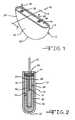
- FIG. 1is a perspective view of an exemplary alkali metal-halogen cell 10 housed in a bead blast conditioned casing 12 according to the present invention.
- FIG. 2is an enlarged sectional view taken about on line 2 - 2 in FIG. 1 .
- FIG. 3illustrates a perspective view of an embodiment of casings of the alkali metal-halogen cell 10 in an as received condition.
- FIG. 4illustrates a perspective view of an embodiment of a fixture used to hold the casings 12 during the bead blasting process.
- FIG. 5shows a perspective view of an embodiment of the casings 12 being bead blasted according to the method of the present invention.
- FIGS. 1 and 2there is shown an exemplary alkali metal-halogen electrochemical cell 10 housed inside of a casing 12 in which its surface has been conditioned through a bead blasting treatment according to the present invention.
- the casing 12is of a metal such as stainless steel and includes spaced apart sidewalls 14 , 16 joined by curved end walls 18 , 20 and a curved bottom wall 22 .
- stainless steelis the preferred casing material, it is contemplated that other materials such as titanium, mild steel, nickel plated steel, aluminum, or nickel cobalt alloys may be used.
- the casing 12prior to assembly of the cell 10 , the casing 12 is bead blasted for a period of time sufficient to render the inner surface 24 of the casing essentially free of contaminants to ensure satisfactory electrical performance of the cell during discharge.
- the casing 12is subjected to a pressurized stream of beads for about 2 to about 10 seconds.
- a pressurefrom about 0.34 MPa (50 psi) to about 0.48 MPa (70 psi) may be used.
- the composition of the beadsis non-limiting and may comprise a metal, a ceramic material such as alumina or zirconia, or a glass.
- glass beads having a grain size from about 35 ⁇ m to about 65 ⁇ m, per MIL SPEC “G”—9954Aare used during the bead blasting process.
- the conditioned casingis ready for cell assembly after a final rinse in deionized water.
- casings 12in an as received condition, are positioned in a bead-blasting fixture 60 .
- the fixture 60as shown in FIG. 4 , comprises a fixture lid 62 , a fixture base plate 64 and left and right fixture sidewalls 66 , 68 positioned therebetween.
- the fixture sidewalls 66 , 68serve as support structures between the lid 62 and base plate 64 .
- the fixture base plate 64comprises a series of openings 70 that extend widthwise along the length of the lid 62 .
- Each of the series of openings 70extends through the thickness of the base plate 64 .
- each of the openings 70has a recess 72 with an annular lip 74 .
- the fixture openings 70are designed such that the annular lip 74 of the openings 70 align with a case rim 76 that surrounds the opening 78 of the cell case 12 ( FIG. 3 ).
- the fixture openings 70provide respective passageways that communicate with the case opening 78 to the inner surface 24 of the case 12 .
- the lid 62is placed across the left and right sidewalls 66 , 68 , enclosing the cases 12 therewithin.
- a spacer 80preferably composed of a soft material such as foam or rubber is attached to the bottom surface of the fixture lid 62 .
- the spacer 80provides a cushion between the bottom of the fixture lid 62 and curved casing bottom wall 22 and ensures a snug fit therebetween.
- Alignment pins 82extend from a top surface of the left and right sidewalls 66 , 68 . These pins 82 are positioned within lid openings 84 .
- a wing nut 86is preferably positioned through fixture slot 88 and is secured down within each of the fixture sidewalls 66 , 68 enclosing the cases 12 therewithin.
- a pressurized stream of beads 90is directed towards the openings 70 of the fixture 60 .
- the stream of beads 90exits a bead-blasting nozzle 92 and passes through the fixture opening 70 , entering the case opening 78 and contacting the inner surface 24 of the case 12 .
- the stream of beads 90impinge the inner surface 24 of the case 12 , thereby removing any surface contamination thereof.
- bombardment of the beads against the inner surface 24 of the case 12roughens the surface, thereby increasing its surface area.
- the surface area of the inner surface 24 of the case 12is increased, thus increasing the chemical reaction rate within the cell 10 .
- the stream of beads 90is directed to the next opening 70 and cell case 12 . This process is repeated until each of the cell cases 12 within the fixture 60 is conditioned with the pressurized stream of beads 90 . After each of the cases 12 has been bead blasted, they are then rinsed and dried.
- the electrochemical cell 10 housed inside of the bead blasted casing 12includes an anode, generally designated 26 and comprising alkali metal, preferably in the form of a pair of lithium plates 28 , 30 pressed together and bonded against an anode current collector 32 .
- the anode current collector 32is a portion of the anode conductor means of the cell.
- Anode current collector 32thus is sandwiched between lithium plates 28 , 30 and can be of various forms such as a length of wire, a strand or ribbon, or a mesh or screen.
- Anode current collector 32is of metal such as nickel or nickel, alloy.
- Each of the lithium plates 28 , 30 in the cell of FIG. 2has generally planar, oppositely directed parallel surfaces.
- Lithium plate 28is identical to lithium plate 30 in size and peripheral outline, the two plates being in registry or in alignment when pressed together.
- the lithium anodemay also be deposited on the anode current collector 32 by vacuum deposition, electroplating or other conventional methods
- the cathode material 36preferably comprises a charge transfer complex of an organic material and iodine, although any other cathode active material may be used that is electronically conductive and contains available iodine for the electrochemical reaction.
- Charge transfer complexesare a well-known class of materials that have two components, one an electron donor, the other an electron acceptor, that form weakly bonded complexes that exhibit electronic conductivity higher than either component.
- Suitable charge transfer complexes for this inventionconsist of an organic donor component and iodine, the electron acceptor, preferably has a conductivity of greater than about 2.5 ⁇ 10 ⁇ 4 ohm/cm.
- the charge transfer complexesare in chemical equilibrium with some small amount of free iodine that is available for electrochemical reaction. These charge transfer complexes have a wide range of electronic conductivity. If the conductivity is low, the current output will be comparatively low because of the high internal ohmic resistance. Cathodes containing intimate mixtures of such low conductivity complexes with powdered graphite or inert metal have high conductivities and can provide electrical discharge performance comparable to cells using high conductivity complexes.
- the cathode material 36is prepared by heating the organic material mixed with iodine to a temperature greater than the crystallization temperature of iodine, for example about 300° F.
- the amount of iodineshould be greater than about 50 percent by weight of the resulting mixture so that enough iodine is available in the cathode material to provide sufficient conductivity for proper cell operation.
- the resulting mixtureis a viscous, flowable substance, which is preferably introduced into the cell casing 12 by flowing it through the above mentioned fill opening in lid 34 .
- a closure element 38preferably also of stainless steel, or the like, is welded to the lid 34 in the fill opening and a terminal lead 40 is spot welded to closure, either before or after the closure element 38 is welded to lid 34 .
- Suitable charge transfer complexesmay be prepared using as organic donor components polycyclic aromatic compounds, such as, for example, pyrene, perylene, anthracene, naphthalene, erythrosine, azulene and fluorene; organic polymers, such as, for example, polyethylene, polypropylene, polystyrene, polypyrrole, polyamides and polyvinyls; or heterocyclic compounds, containing nitrogen or sulfur, such as, for example, phenothiazine, phenazine, 10-phenylphenophiozine, thianthrene, 10-methylthiazinc and methalyineblue; and polymerized or polymerizable compounds in which a heterocyclic nitrogen moiety is incorporated as a side chain or substituent, especially vinyl compounds and polymers, such as poly-2-vinyl quinoline, poly-2-vinyl pyridine, poly-4-vinyl pyridine, poly-5-vinyl-2-methyl-pyridine and poly-
- the proportions of iodine to organic componentcan be varied over a wide range, although a high proportion of uncomplexed iodine in the cathode generally increases internal cell resistance.
- Other iodine containing cathodes that are electronically conductivemay also be used, such as mixtures of iodine and carbon or graphite.
- a lithium iodide electrolyte 42is formed in situ by reaction of the iodine present in the cathode with the lithium anode. It is equally satisfactory, and in some instances preferable, to form a film of lithium salt electrolyte on the anode surface abutting the cathode prior to cell assembly. That's done most conveniently by exposing the anode surface to dry air or argon atmosphere containing halogen gas or vapor. It will be recognized that additional lithium iodide electrolyte is formed by the electrochemical reaction of the cell.
- a strip or band of electrical insulating material 44serves to insulate anode 26 from the metal lid 34 of casing 12 in a completed or assembled cell.
- An anode lead(not shown) extends from the anode current collector 32 through a glass-to-metal seal serves an insulator and seal structure 46 and becomes an anode terminal lead 46 , which extends through lid 34 .
- an alkali metal-halogen cellreference may be made to U.S. Pat. No. 4,401,736 issued Aug. 30, 1983 entitled “Anode Assembly For Lithium Halogen Cell” and assigned to the assignee of the present invention, the disclosure of which is hereby incorporated by reference.
- the above described exemplary alkali metal-halogen electrochemical cell housed in the bead blasted casing according to the present inventionperforms as well as or better than a comparable cell having a case treated by the more costly acid-cleaning and electro-polishing processes of the prior art.
- Lithium/iodine cells of case-positive configurations similar in construction to the exemplary alkali metal-halide cell 10 just describedwere used as test vehicles.
- the cellswere constructed to deliver rate capacities of 1.32 Ah.
- Stainless steel caseswere conditioned using the three methods previously discussed, conventional chemical etching, conventional electro-polishing and bead blasting according to the present invention.
- Three groups of cellswere fabricated, group “A” in which the casings were bead blasted according to the present invention, a prior art group “B” in which the casings were electro-polished using a solution of about 20 volume percent perchioric acid and about 80 volume percent acetic acid, and a prior art group “C” in which the casing were treated using Diversey® chemical etchant.
- alkali metal-halogen cellstypically are characterized by high loaded voltages and low internal impedances.
- the cells comprising the bead blasted case surface according to the present inventionexhibited electrical discharge characteristics equaling or exceeding those of cells housed in acid treated or electro-polished cases.
- the bead blasting process of the present inventionis seen to have caused the cathodic current collectors, i.e., the inner case surfaces, to perform as effectively as those which have been acid-treated or electro-polished according to the prior art.
- High loaded cell voltageis maintained and internal impedance is typically lowered for the present invention cells in comparison to those of a comparable chemistry housed in casings having their internal surfaces treated according to the prior art.
- the bead blasted cellsnot only have a greater high loaded cell voltage output averaging about 2,724 my, but also have the lowest standard deviation of about 3 mV, it is, therefore, believed that the case conditioning afforded by the bead blasting method of the present invention improves voltage output performance and manufacturability of alkali metal-halogen electrochemical cells.
Landscapes
- Engineering & Computer Science (AREA)
- Chemical & Material Sciences (AREA)
- Chemical Kinetics & Catalysis (AREA)
- Electrochemistry (AREA)
- General Chemical & Material Sciences (AREA)
- Manufacturing & Machinery (AREA)
- Mechanical Engineering (AREA)
- Inorganic Chemistry (AREA)
- Primary Cells (AREA)
Abstract
Description
Li→Li++e−
and the cathode reaction is:
I2+2e−→2I−
giving an overall reaction of:
2Li+I2→2LiI
| TABLE I | |||||
| Final 100K | Final 100K loaded | ||||
| S/N | Group | loaded voltage, mv | impedance, ohms | ||
| 711 | A | 2,726 | 86 | ||
| 712 | 2,725 | 88 | |||
| 713 | 2,726 | 85 | |||
| 714 | 2,731 | 82 | |||
| 715 | 2,727 | 84 | |||
| 716 | 2,725 | 85 | |||
| 717 | 2,726 | 90 | |||
| 718 | 2,718 | 97 | |||
| 719 | 2,719 | 100 | |||
| 720 | 2,721 | 95 | |||
| 721 | 2,718 | 97 | |||
| 722 | 2,722 | 94 | |||
| 723 | 2,723 | 91 | |||
| 724 | 2,724 | 92 | |||
| 725 | 2,727 | 86 | |||
| 726 | 2,723 | 93 | |||
| 727 | 2,726 | 88 | |||
| 728 | 2,726 | 83 | |||
| 729 | 2,725 | 89 | |||
| 730 | 2,724 | 92 | |||
| 731 | 2,726 | 87 | |||
| 732 | 2,726 | 90 | |||
| 733 | 2,726 | 89 | |||
| 734 | 2,719 | 98 | |||
| 735 | 2,721 | 96 | |||
| 2,724 +/− 3 | 90 +/− 5 | ||||
| 686 | B | 2,694 | 94 | ||
| 687 | 2,708 | 94 | |||
| 688 | 2,693 | 96 | |||
| 689 | 2,688 | 92 | |||
| 690 | 2,698 | 93 | |||
| 691 | 2,695 | 100 | |||
| 692 | 2,690 | 94 | |||
| 693 | 2,685 | 95 | |||
| 694 | 2,696 | 102 | |||
| 695 | 2,687 | 100 | |||
| 696 | 2,700 | 97 | |||
| 697 | 2,687 | 102 | |||
| 698 | 2,682 | 94 | |||
| 699 | 2,699 | 90 | |||
| 700 | 2,697 | 89 | |||
| 701 | 2,682 | 89 | |||
| 702 | 2,679 | 88 | |||
| 703 | 2,677 | 92 | |||
| 704 | 2,675 | 91 | |||
| 705 | 2,678 | 89 | |||
| 706 | 2,699 | 92 | |||
| 707 | 2,700 | 85 | |||
| 708 | 2,704 | 87 | |||
| 709 | 2,702 | 89 | |||
| 710 | 2,707 | 94 | |||
| 2,692 +/− 10 | 95 +/− 5 | ||||
| 661 | C | 2,687 | 89 | ||
| 662 | 2,679 | 93 | |||
| 663 | 2,665 | 92 | |||
| 665 | 2,694 | 82 | |||
| 666 | 2,671 | 84 | |||
| 667 | 2,670 | 91 | |||
| 668 | 2,669 | 92 | |||
| 669 | 2,679 | 87 | |||
| 670 | 2,687 | 84 | |||
| 671 | 2,657 | 92 | |||
| 672 | 2,656 | 87 | |||
| 673 | 2,678 | 97 | |||
| 674 | 2,658 | 86 | |||
| 675 | 2,688 | 94 | |||
| 676 | 2,698 | 85 | |||
| 677 | 2,661 | 85 | |||
| 678 | 2,673 | 87 | |||
| 679 | 2,699 | 88 | |||
| 680 | 2,684 | 88 | |||
| 681 | 2,683 | 90 | |||
| 682 | 2,653 | 91 | |||
| 683 | 2,671 | 87 | |||
| 684 | 2,686 | 85 | |||
| 685 | 2,680 | 87 | |||
| 2,676 +/− 13 | 88 +/− 4 | ||||
Claims (22)
Priority Applications (2)
| Application Number | Priority Date | Filing Date | Title |
|---|---|---|---|
| US13/340,217US9293741B1 (en) | 2010-12-29 | 2011-12-29 | Mechanical conditioning by bead blasting lithium iodine cell case |
| US15/073,706US10141545B2 (en) | 2010-12-29 | 2016-03-18 | Mechanical conditioning by bead blasting lithium iodine cell case |
Applications Claiming Priority (2)
| Application Number | Priority Date | Filing Date | Title |
|---|---|---|---|
| US201061427924P | 2010-12-29 | 2010-12-29 | |
| US13/340,217US9293741B1 (en) | 2010-12-29 | 2011-12-29 | Mechanical conditioning by bead blasting lithium iodine cell case |
Related Child Applications (1)
| Application Number | Title | Priority Date | Filing Date |
|---|---|---|---|
| US15/073,706DivisionUS10141545B2 (en) | 2010-12-29 | 2016-03-18 | Mechanical conditioning by bead blasting lithium iodine cell case |
Publications (1)
| Publication Number | Publication Date |
|---|---|
| US9293741B1true US9293741B1 (en) | 2016-03-22 |
Family
ID=55487489
Family Applications (2)
| Application Number | Title | Priority Date | Filing Date |
|---|---|---|---|
| US13/340,217Active2033-03-31US9293741B1 (en) | 2010-12-29 | 2011-12-29 | Mechanical conditioning by bead blasting lithium iodine cell case |
| US15/073,706Active2032-10-25US10141545B2 (en) | 2010-12-29 | 2016-03-18 | Mechanical conditioning by bead blasting lithium iodine cell case |
Family Applications After (1)
| Application Number | Title | Priority Date | Filing Date |
|---|---|---|---|
| US15/073,706Active2032-10-25US10141545B2 (en) | 2010-12-29 | 2016-03-18 | Mechanical conditioning by bead blasting lithium iodine cell case |
Country Status (1)
| Country | Link |
|---|---|
| US (2) | US9293741B1 (en) |
Families Citing this family (20)
| Publication number | Priority date | Publication date | Assignee | Title |
|---|---|---|---|---|
| CA2903843C (en) | 2013-03-15 | 2019-03-05 | Alfred E. Mann Foundation For Scientific Research | Current sensing multiple output current stimulators with fast turn on time |
| US9780596B2 (en) | 2013-07-29 | 2017-10-03 | Alfred E. Mann Foundation For Scientific Research | Microprocessor controlled class E driver |
| ES2782556T3 (en) | 2014-08-15 | 2020-09-15 | Axonics Modulation Tech Inc | System for neurostimulation electrode configurations based on neuronal location |
| AU2015301398B2 (en) | 2014-08-15 | 2020-05-21 | Axonics Modulation Technologies, Inc. | Implantable lead affixation structure for nerve stimulation to alleviate bladder dysfunction and other indications |
| AU2015301401B2 (en) | 2014-08-15 | 2020-01-16 | Axonics Modulation Technologies, Inc. | Electromyographic lead positioning and stimulation titration in a nerve stimulation system for treatment of overactive bladder |
| CA2958210C (en) | 2014-08-15 | 2023-09-26 | Axonics Modulation Technologies, Inc. | Integrated electromyographic clinician programmer for use with an implantable neurostimulator |
| CA3208375A1 (en) | 2014-08-15 | 2016-02-18 | Axonics, Inc. | External pulse generator device and associated methods for trial nerve stimulation |
| JP6751718B2 (en) | 2015-01-09 | 2020-09-09 | アクソニクス モジュレーション テクノロジーズ インコーポレイテッド | Mounting devices and related methods for use with neurostimulation charging devices |
| CN107427675B (en) | 2015-01-09 | 2021-10-26 | 艾克索尼克斯股份有限公司 | Patient remote control and associated method for use with a neurostimulation system |
| CA2973192C (en) | 2015-01-09 | 2023-04-04 | Axonics Modulation Technologies, Inc. | Improved antenna and methods of use for an implantable nerve stimulator |
| AU2016291554B2 (en) | 2015-07-10 | 2021-01-07 | Axonics Modulation Technologies, Inc. | Implantable nerve stimulator having internal electronics without ASIC and methods of use |
| JP6876363B2 (en) | 2016-01-29 | 2021-05-26 | アクソニクス モジュレーション テクノロジーズ インコーポレイテッド | Methods and systems for frequency adjustment that optimize the charging of implantable neurostimulators |
| WO2017139784A1 (en) | 2016-02-12 | 2017-08-17 | Axonics Modulation Technologies, Inc. | External pulse generator device and associated methods for trial nerve stimulation |
| US10790482B2 (en)* | 2017-08-04 | 2020-09-29 | Greatbatch Ltd. | Lithium-iodine electrochemical cells exhibiting low discharge impedance |
| WO2019165108A1 (en) | 2018-02-22 | 2019-08-29 | Axonics Modulation Technologies, Inc. | Neurostimulation leads for trial nerve stimulation and methods of use |
| US11642537B2 (en) | 2019-03-11 | 2023-05-09 | Axonics, Inc. | Charging device with off-center coil |
| US11439829B2 (en) | 2019-05-24 | 2022-09-13 | Axonics, Inc. | Clinician programmer methods and systems for maintaining target operating temperatures |
| WO2020242900A1 (en) | 2019-05-24 | 2020-12-03 | Axonics Modulation Technologies, Inc. | Trainer device for a neurostimulator programmer and associated methods of use with a neurostimulation system |
| US12420103B1 (en) | 2020-08-20 | 2025-09-23 | Axonics, Inc. | Neurostimulation leads with reduced current leakage |
| DE102023101908A1 (en)* | 2023-01-26 | 2024-08-01 | Bayerische Motoren Werke Aktiengesellschaft | Method for removing a process material from a cell housing of a battery cell of a battery module, battery cell and vehicle |
Citations (12)
| Publication number | Priority date | Publication date | Assignee | Title |
|---|---|---|---|---|
| US3601601A (en)* | 1969-07-24 | 1971-08-24 | Progressive Products Co | Battery encased in a functional unit |
| JPS5812262A (en)* | 1981-06-30 | 1983-01-24 | Toshiba Battery Co Ltd | Organic solvent cell |
| US5604055A (en)* | 1996-02-16 | 1997-02-18 | Wilson Greatbatch Ltd. | Oxidized alkali metal-halogen cell case |
| US5704239A (en) | 1996-01-11 | 1998-01-06 | Smith & Nephew, Inc. | Method for ceramic peening of orthopaedic titanium alloy implants |
| US5773087A (en) | 1991-11-15 | 1998-06-30 | Sumitomo Electric Industries, Ltd. | Coated article and method for producing same |
| US6150033A (en) | 1995-06-06 | 2000-11-21 | Sermatech International, Inc. | Environmentally friendly coating compositions, bonding solution, and coated parts |
| US20020000033A1 (en)* | 2000-06-30 | 2002-01-03 | Hideyuki Tajima | Method for manufacturing a gas sensor |
| US6544351B2 (en) | 2001-07-12 | 2003-04-08 | General Electric Company | Compositions and methods for producing coatings with improved surface smoothness and articles having such coatings |
| US6584820B1 (en) | 1999-09-23 | 2003-07-01 | Polyclad Laminates, Inc. | Surface enhanced metal press plates for use in manufacture of laminates and multilayer materials and method of making same |
| US6866562B2 (en) | 2000-08-10 | 2005-03-15 | Megara (Australia) Pty Ltd | Finishing of metal surfaces and related applications |
| US7168142B2 (en) | 2003-09-15 | 2007-01-30 | Greatbatch-Globe Tool, Inc. | Method of manufacturing a shaped titanium article |
| US7815357B2 (en) | 2004-09-28 | 2010-10-19 | Mitsubishi Rayon Co., Ltd. | Light guide for surface light source device and surface light source device |
Family Cites Families (3)
| Publication number | Priority date | Publication date | Assignee | Title |
|---|---|---|---|---|
| US4359818A (en)* | 1981-01-05 | 1982-11-23 | Wilson Greatbatch Ltd. | Coated anode for lithium halogen cells |
| US5576113A (en)* | 1993-06-04 | 1996-11-19 | Katayama Special Industries, Ltd. | Battery can, sheet for forming battery can, and method for manufacturing sheet |
| US5455123A (en)* | 1994-02-14 | 1995-10-03 | Medtronic, Inc. | Method for making an electrochemical cell |
- 2011
- 2011-12-29USUS13/340,217patent/US9293741B1/enactiveActive
- 2016
- 2016-03-18USUS15/073,706patent/US10141545B2/enactiveActive
Patent Citations (12)
| Publication number | Priority date | Publication date | Assignee | Title |
|---|---|---|---|---|
| US3601601A (en)* | 1969-07-24 | 1971-08-24 | Progressive Products Co | Battery encased in a functional unit |
| JPS5812262A (en)* | 1981-06-30 | 1983-01-24 | Toshiba Battery Co Ltd | Organic solvent cell |
| US5773087A (en) | 1991-11-15 | 1998-06-30 | Sumitomo Electric Industries, Ltd. | Coated article and method for producing same |
| US6150033A (en) | 1995-06-06 | 2000-11-21 | Sermatech International, Inc. | Environmentally friendly coating compositions, bonding solution, and coated parts |
| US5704239A (en) | 1996-01-11 | 1998-01-06 | Smith & Nephew, Inc. | Method for ceramic peening of orthopaedic titanium alloy implants |
| US5604055A (en)* | 1996-02-16 | 1997-02-18 | Wilson Greatbatch Ltd. | Oxidized alkali metal-halogen cell case |
| US6584820B1 (en) | 1999-09-23 | 2003-07-01 | Polyclad Laminates, Inc. | Surface enhanced metal press plates for use in manufacture of laminates and multilayer materials and method of making same |
| US20020000033A1 (en)* | 2000-06-30 | 2002-01-03 | Hideyuki Tajima | Method for manufacturing a gas sensor |
| US6866562B2 (en) | 2000-08-10 | 2005-03-15 | Megara (Australia) Pty Ltd | Finishing of metal surfaces and related applications |
| US6544351B2 (en) | 2001-07-12 | 2003-04-08 | General Electric Company | Compositions and methods for producing coatings with improved surface smoothness and articles having such coatings |
| US7168142B2 (en) | 2003-09-15 | 2007-01-30 | Greatbatch-Globe Tool, Inc. | Method of manufacturing a shaped titanium article |
| US7815357B2 (en) | 2004-09-28 | 2010-10-19 | Mitsubishi Rayon Co., Ltd. | Light guide for surface light source device and surface light source device |
Non-Patent Citations (1)
| Title |
|---|
| Yoshizaki et al., English abstract of JP 58-012262 A, Jan. 1983.* |
Also Published As
| Publication number | Publication date |
|---|---|
| US10141545B2 (en) | 2018-11-27 |
| US20160204391A1 (en) | 2016-07-14 |
Similar Documents
| Publication | Publication Date | Title |
|---|---|---|
| US10141545B2 (en) | Mechanical conditioning by bead blasting lithium iodine cell case | |
| US5867363A (en) | Energy storage device | |
| EP0755306B1 (en) | Improved energy storage device and methods of manufacture | |
| US7813107B1 (en) | Wet tantalum capacitor with multiple anode connections | |
| WO1990013150A1 (en) | Lithium/organosulfur redox cell having protective solid electrolyte barrier formed on anode and method of making same | |
| US20050095506A1 (en) | Lithium/air batteries with LiPON as separator and protective barrier and method | |
| US11043674B2 (en) | Battery electrode with carbon additives in meta-solid-state battery | |
| JPH0794172A (en) | Electrochemical cell, its anode, and method of coating anode | |
| JPH0343751B2 (en) | ||
| JPS62501248A (en) | Electrochemical cell with wound electrode structure | |
| JP2001052712A (en) | Lithium ion battery with oxidation / reduction negative current collector | |
| KR101009300B1 (en) | Accumulators with foam carbon current collectors | |
| US4283469A (en) | Integrated electrode/separator structures | |
| AU668547B2 (en) | An electrode plate construction | |
| EP3333964B1 (en) | Treatment processes for electrochemical cells | |
| JP2006517719A (en) | Secondary battery with polymer-coated anode | |
| US3944433A (en) | Lithium iodine battery having improved energy density | |
| US5604055A (en) | Oxidized alkali metal-halogen cell case | |
| JP2000513491A (en) | Improvement of conductivity at collector electrode interface in stacked lithium ion rechargeable batteries | |
| US4683648A (en) | Lead-titanium, bipolar electrode in a lead-acid battery | |
| JP2623311B2 (en) | Manufacturing method of electrode plate for bipolar battery | |
| US2663749A (en) | Primary cell | |
| EP3439077B1 (en) | Lithium-iodine electrochemical cells exhibiting low discharge impedance | |
| US4251608A (en) | Lead-sulfuric acid battery with stainless steel or titanium grid | |
| JPH09195094A (en) | Supporting body for electrochemical film formation |
Legal Events
| Date | Code | Title | Description |
|---|---|---|---|
| AS | Assignment | Owner name:GREATBATCH LTD., NEW YORK Free format text:ASSIGNMENT OF ASSIGNORS INTEREST;ASSIGNORS:KRAFT, GLENN J.;MONRIAN, JACQUELYN S.;REEL/FRAME:027461/0513 Effective date:20111214 | |
| AS | Assignment | Owner name:MANUFACTURERS AND TRADERS TRUST COMPANY, NEW YORK Free format text:SECURITY INTEREST;ASSIGNORS:GREATBATCH, INC.;GREATBATCH LTD.;ELECTROCHEM SOLUTIONS, INC.;AND OTHERS;REEL/FRAME:036980/0482 Effective date:20151027 | |
| STCF | Information on status: patent grant | Free format text:PATENTED CASE | |
| CC | Certificate of correction | ||
| MAFP | Maintenance fee payment | Free format text:PAYMENT OF MAINTENANCE FEE, 4TH YEAR, LARGE ENTITY (ORIGINAL EVENT CODE: M1551); ENTITY STATUS OF PATENT OWNER: LARGE ENTITY Year of fee payment:4 | |
| AS | Assignment | Owner name:WELLS FARGO BANK, NATIONAL ASSOCIATION, AS ADMINISTRATIVE AGENT, VIRGINIA Free format text:SECURITY INTEREST;ASSIGNORS:GREATBATCH LTD.;ELECTROCHEM SOLUTIONS, INC.;LAKE REGION MEDICAL, INC.;AND OTHERS;REEL/FRAME:057468/0056 Effective date:20210902 | |
| AS | Assignment | Owner name:MICRO POWER ELECTRONICS, INC., NEW YORK Free format text:RELEASE BY SECURED PARTY;ASSIGNOR:MANUFACTURERS AND TRADERS TRUST COMPANY (AS ADMINISTRATIVE AGENT);REEL/FRAME:060938/0069 Effective date:20210903 Owner name:PRECIMED INC., NEW YORK Free format text:RELEASE BY SECURED PARTY;ASSIGNOR:MANUFACTURERS AND TRADERS TRUST COMPANY (AS ADMINISTRATIVE AGENT);REEL/FRAME:060938/0069 Effective date:20210903 Owner name:GREATBATCH-GLOBE TOOL, INC., NEW YORK Free format text:RELEASE BY SECURED PARTY;ASSIGNOR:MANUFACTURERS AND TRADERS TRUST COMPANY (AS ADMINISTRATIVE AGENT);REEL/FRAME:060938/0069 Effective date:20210903 Owner name:NEURONEXUS TECHNOLOGIES, INC., NEW YORK Free format text:RELEASE BY SECURED PARTY;ASSIGNOR:MANUFACTURERS AND TRADERS TRUST COMPANY (AS ADMINISTRATIVE AGENT);REEL/FRAME:060938/0069 Effective date:20210903 Owner name:ELECTROCHEM SOLUTIONS, INC., NEW YORK Free format text:RELEASE BY SECURED PARTY;ASSIGNOR:MANUFACTURERS AND TRADERS TRUST COMPANY (AS ADMINISTRATIVE AGENT);REEL/FRAME:060938/0069 Effective date:20210903 Owner name:GREATBATCH LTD., NEW YORK Free format text:RELEASE BY SECURED PARTY;ASSIGNOR:MANUFACTURERS AND TRADERS TRUST COMPANY (AS ADMINISTRATIVE AGENT);REEL/FRAME:060938/0069 Effective date:20210903 Owner name:GREATBATCH, INC., NEW YORK Free format text:RELEASE BY SECURED PARTY;ASSIGNOR:MANUFACTURERS AND TRADERS TRUST COMPANY (AS ADMINISTRATIVE AGENT);REEL/FRAME:060938/0069 Effective date:20210903 | |
| AS | Assignment | Owner name:MICRO POWER ELECTRONICS, INC., NEW YORK Free format text:RELEASE BY SECURED PARTY;ASSIGNOR:MANUFACTURERS AND TRADERS TRUST COMPANY (AS ADMINISTRATIVE AGENT);REEL/FRAME:061659/0858 Effective date:20210903 Owner name:PRECIMED INC., NEW YORK Free format text:RELEASE BY SECURED PARTY;ASSIGNOR:MANUFACTURERS AND TRADERS TRUST COMPANY (AS ADMINISTRATIVE AGENT);REEL/FRAME:061659/0858 Effective date:20210903 Owner name:GREATBATCH-GLOBE TOOL, INC., NEW YORK Free format text:RELEASE BY SECURED PARTY;ASSIGNOR:MANUFACTURERS AND TRADERS TRUST COMPANY (AS ADMINISTRATIVE AGENT);REEL/FRAME:061659/0858 Effective date:20210903 Owner name:NEURONEXUS TECHNOLOGIES, INC., NEW YORK Free format text:RELEASE BY SECURED PARTY;ASSIGNOR:MANUFACTURERS AND TRADERS TRUST COMPANY (AS ADMINISTRATIVE AGENT);REEL/FRAME:061659/0858 Effective date:20210903 Owner name:ELECTROCHEM SOLUTIONS, INC., NEW YORK Free format text:RELEASE BY SECURED PARTY;ASSIGNOR:MANUFACTURERS AND TRADERS TRUST COMPANY (AS ADMINISTRATIVE AGENT);REEL/FRAME:061659/0858 Effective date:20210903 Owner name:GREATBATCH LTD., NEW YORK Free format text:RELEASE BY SECURED PARTY;ASSIGNOR:MANUFACTURERS AND TRADERS TRUST COMPANY (AS ADMINISTRATIVE AGENT);REEL/FRAME:061659/0858 Effective date:20210903 Owner name:GREATBATCH, INC., NEW YORK Free format text:RELEASE BY SECURED PARTY;ASSIGNOR:MANUFACTURERS AND TRADERS TRUST COMPANY (AS ADMINISTRATIVE AGENT);REEL/FRAME:061659/0858 Effective date:20210903 | |
| MAFP | Maintenance fee payment | Free format text:PAYMENT OF MAINTENANCE FEE, 8TH YEAR, LARGE ENTITY (ORIGINAL EVENT CODE: M1552); ENTITY STATUS OF PATENT OWNER: LARGE ENTITY Year of fee payment:8 |