US9292138B2 - Single layer sensor pattern - Google Patents
Single layer sensor patternDownload PDFInfo
- Publication number
- US9292138B2 US9292138B2US13/904,481US201313904481AUS9292138B2US 9292138 B2US9292138 B2US 9292138B2US 201313904481 AUS201313904481 AUS 201313904481AUS 9292138 B2US9292138 B2US 9292138B2
- Authority
- US
- United States
- Prior art keywords
- subelements
- small
- subelement
- sensor array
- sensor electrodes
- Prior art date
- Legal status (The legal status is an assumption and is not a legal conclusion. Google has not performed a legal analysis and makes no representation as to the accuracy of the status listed.)
- Active
Links
Images


Classifications
- G—PHYSICS
- G06—COMPUTING OR CALCULATING; COUNTING
- G06F—ELECTRIC DIGITAL DATA PROCESSING
- G06F3/00—Input arrangements for transferring data to be processed into a form capable of being handled by the computer; Output arrangements for transferring data from processing unit to output unit, e.g. interface arrangements
- G06F3/01—Input arrangements or combined input and output arrangements for interaction between user and computer
- G06F3/03—Arrangements for converting the position or the displacement of a member into a coded form
- G06F3/041—Digitisers, e.g. for touch screens or touch pads, characterised by the transducing means
- G06F3/044—Digitisers, e.g. for touch screens or touch pads, characterised by the transducing means by capacitive means
- G06F3/0446—Digitisers, e.g. for touch screens or touch pads, characterised by the transducing means by capacitive means using a grid-like structure of electrodes in at least two directions, e.g. using row and column electrodes
- G—PHYSICS
- G06—COMPUTING OR CALCULATING; COUNTING
- G06F—ELECTRIC DIGITAL DATA PROCESSING
- G06F3/00—Input arrangements for transferring data to be processed into a form capable of being handled by the computer; Output arrangements for transferring data from processing unit to output unit, e.g. interface arrangements
- G06F3/01—Input arrangements or combined input and output arrangements for interaction between user and computer
- G06F3/03—Arrangements for converting the position or the displacement of a member into a coded form
- G06F3/041—Digitisers, e.g. for touch screens or touch pads, characterised by the transducing means
- G06F3/044—Digitisers, e.g. for touch screens or touch pads, characterised by the transducing means by capacitive means
- G—PHYSICS
- G06—COMPUTING OR CALCULATING; COUNTING
- G06F—ELECTRIC DIGITAL DATA PROCESSING
- G06F2203/00—Indexing scheme relating to G06F3/00 - G06F3/048
- G06F2203/041—Indexing scheme relating to G06F3/041 - G06F3/045
- G06F2203/04111—Cross over in capacitive digitiser, i.e. details of structures for connecting electrodes of the sensing pattern where the connections cross each other, e.g. bridge structures comprising an insulating layer, or vias through substrate
Definitions
- This disclosurerelates to the field of touch-sensors and, in particular, to trace patterns of electrodes in capacitive touch-sensor arrays.
- Computing devicessuch as notebook computers, personal data assistants (PDAs), kiosks, and mobile handsets, have user interface devices, which are also known as human interface devices (HID).
- user interface deviceswhich are also known as human interface devices (HID).
- One user interface device that has become more commonis a touch-sensor pad (also commonly referred to as a touchpad).
- a basic notebook computer touch-sensor pademulates the function of a personal computer (PC) mouse.
- a touch-sensor padis typically embedded into a PC notebook for built-in portability.
- a touch-sensor padreplicates mouse X/Y movement by using two defined axes which contain a collection of sensor electrodes that detect the position of one or more conductive objects, such as a finger.
- Mouse right/left button clickscan be replicated by two mechanical buttons, located in the vicinity of the touchpad, or by tapping commands on the touch-sensor pad itself.
- the touch-sensor padprovides a user interface device for performing such functions as positioning a pointer, or selecting an item on a display.
- These touch-sensor padsmay include multi-dimensional sensor arrays for detecting movement in multiple axes.
- the sensor arraymay include a one-dimensional sensor array, detecting movement in one axis.
- the sensor arraymay also be two dimensional, detecting movements in two axes.
- Touch screensalso known as touchscreens, touch windows, touch panels, or touchscreen panels
- transparent display overlayswhich are typically either pressure-sensitive (resistive or piezoelectric), electrically-sensitive (capacitive), acoustically-sensitive (surface acoustic wave (SAW)) or photo-sensitive (infra-red).
- SAWsurface acoustic wave
- the effect of such overlaysallows a display to be used as an input device, removing the keyboard and/or the mouse as the primary input device for interacting with the display's content.
- Such displayscan be attached to computers or, as terminals, to networks.
- Touch screenshave become familiar in retail settings, on point-of-sale systems, on ATMs, on mobile handsets, on kiosks, on game consoles, and on PDAs where a stylus is sometimes used to manipulate the graphical user interface (GUI) and to enter data.
- GUIgraphical user interface
- a usercan touch a touch screen or a touch-sensor pad to manipulate data. For example, a user can apply a single touch, by using a finger to touch the surface of a touch screen, to select an item from a menu.
- FIG. 1is a block diagram illustrating an embodiment of an electronic system that processes touch sensor data.
- FIG. 2is a block diagram illustrating an embodiment of an electronic system that processes touch sensor data.
- FIG. 3Aillustrates an embodiment of an electronic touch-sensing system using a dual solid diamond capacitive sensor pattern.
- FIG. 3Billustrates an embodiment of a dual solid diamond capacitive sensor pattern.
- FIG. 4Aillustrates components of a touch screen assembly, according to an embodiment.
- FIG. 4Billustrates components of a touch screen assembly, according to an embodiment.
- FIG. 5Aillustrates a portion of a sensor array pattern, according to an embodiment.
- FIGS. 5B and 5Cillustrate embodiments of sensor array patterns.
- FIG. 6Aillustrates an embodiment of a sensor array.
- FIG. 6Billustrates electrical connections between a sensor array and a capacitance sensor, according to an embodiment.
- FIG. 7illustrates an embodiment of a sensor array.
- FIGS. 8A and 8Billustrate embodiments of sensor array patterns.
- FIGS. 9A, 9B, 9C, and 9Dillustrate embodiments of sensor array patterns.
- FIGS. 10A and 10Billustrate embodiments of sensor arrays with one or more bezels.
- the patternmay include a single layer of copper, indium-tin oxide (ITO), or other conductive material without any overlapping portions.
- ITOindium-tin oxide
- such a single layer of conductive materialmay include different types of conductive materials.
- part of the single layermay be constructed from ITO while another part may be constructed from copper.
- substantially all portions of the single layer of conductive materialmay lie substantially on a single plane or surface.
- the single layer of conductive materialmay conform to the surface of a substrate such as glass or plastic.
- An embodiment of a single-layer sensor array patternmay further maximize its sensitivity to capacitance changes by minimizing the area occupied by routing channels that connect the sensor electrodes to the edge of the capacitive sensor array.
- a single-layer sensor patternmay have a reduced number of electrodes in order to reduce the space occupied by the routing channel; in such an embodiment, the resolution of the sensor pattern may be maintained by subdividing some of the electrodes. In one embodiment, this results in a capacitive sensor array that includes a first set of sensor electrodes each made up of one or more large subelements and a second set of sensor electrodes each made up of one or more smaller subelements. In one embodiment, each of the large sensor electrode subelements may be capacitively coupled with two or more of the smaller subelements. Thus, the resolution of the sensor array is increased because a mutual capacitance can be separately measured between the large subelement and either of the two smaller subelements.
- a capacitance sensor coupled with a capacitive sensor array as described abovemay be used to scan the capacitive sensor array by measuring the self capacitances associated with each sensor electrode, or the mutual capacitances between pairs of sensor electrodes.
- the capacitance sensormay then transmit the measured capacitance values to a host, where the capacitance values may be further processed to determine, for example, locations of fingers or other conductive objects near or touching the surface of the capacitive sensor array.
- the hostcompensates for the capacitance differences between the regions having different patterns of conductive traces.
- FIG. 1illustrates a block diagram of one embodiment of an electronic system 100 including a processing device 110 that may be configured to measure capacitances from a touch sensing surface 116 including a capacitive sensor array as described above.
- the electronic system 100includes a touch-sensing surface 116 (e.g., a touchscreen, or a touch pad) coupled to the processing device 110 and a host 150 .
- the touch-sensing surface 116is a two-dimensional user interface that uses a sensor array 121 to detect touches on the surface 116 .
- the sensor array 121includes sensor electrodes 121 ( 1 )- 121 (N) (where N is a positive integer) that are disposed as a two-dimensional matrix (also referred to as an XY matrix).
- the sensor array 121is coupled to pins 113 ( 1 )- 113 (N) of the processing device 110 via one or more analog buses 115 transporting multiple signals.
- each sensor electrode 121 ( 1 )- 121 (N)is represented as a capacitor.
- the capacitance sensor 101may include a relaxation oscillator or other means to convert a capacitance into a measured value.
- the capacitance sensor 101may also include a counter or timer to measure the oscillator output.
- the processing device 110may further include software components to convert the count value (e.g., capacitance value) into a sensor electrode detection decision (also referred to as switch detection decision) or relative magnitude.
- a sensor electrode detection decisionalso referred to as switch detection decision
- switch detection decisione.g., switch detection decision
- the capacitance sensor 101may be evaluating other measurements to determine the user interaction. For example, in the capacitance sensor 101 having a sigma-delta modulator, the capacitance sensor 101 is evaluating the ratio of pulse widths of the output, instead of the raw counts being over or under a certain threshold.
- the processing device 110further includes processing logic 102 .
- Operations of the processing logic 102may be implemented in firmware; alternatively, it may be implemented in hardware or software.
- the processing logic 102may receive signals from the capacitance sensor 101 , and determine the state of the sensor array 121 , such as whether an object (e.g., a finger) is detected on or in proximity to the sensor array 121 (e.g., determining the presence of the object), where the object is detected on the sensor array (e.g., determining the location of the object), tracking the motion of the object, or other information related to an object detected at the touch sensor.
- an objecte.g., a finger
- the processing logic 102may receive signals from the capacitance sensor 101 , and determine the state of the sensor array 121 , such as whether an object (e.g., a finger) is detected on or in proximity to the sensor array 121 (e.g., determining the presence of the object), where the object is detected on the sensor array (e.g.,
- the processing device 110may send the raw data or partially-processed data to the host 150 .
- the host 150may include decision logic 151 that performs some or all of the operations of the processing logic 102 .
- Operations of the decision logic 151may be implemented in firmware, hardware, software, or a combination thereof.
- the host 150may include a high-level Application Programming Interface (API) in applications 152 that perform routines on the received data, such as compensating for sensitivity differences, other compensation algorithms, baseline update routines, start-up and/or initialization routines, interpolation operations, or scaling operations.
- APIApplication Programming Interface
- the operations described with respect to the processing logic 102may be implemented in the decision logic 151 , the applications 152 , or in other hardware, software, and/or firmware external to the processing device 110 .
- the processing device 110is the host 150 .
- the processing device 110may also include a non-sensing actions block 103 .
- This block 103may be used to process and/or receive/transmit data to and from the host 150 .
- additional componentsmay be implemented to operate with the processing device 110 along with the sensor array 121 (e.g., keyboard, keypad, mouse, trackball, LEDs, displays, or other peripheral devices).
- the processing device 110may reside on a common carrier substrate such as, for example, an integrated circuit (IC) die substrate, or a multi-chip module substrate.
- the components of the processing device 110may be one or more separate integrated circuits and/or discrete components.
- the processing device 110may be the Programmable System on a Chip (PSoCTM) processing device, developed by Cypress Semiconductor Corporation, San Jose, Calif.
- the processing device 110may be one or more other processing devices known by those of ordinary skill in the art, such as a microprocessor or central processing unit, a controller, special-purpose processor, digital signal processor (DSP), an application specific integrated circuit (ASIC), a field programmable gate array (FPGA), or other programmable device.
- the processing device 110may be a network processor having multiple processors including a core unit and multiple micro-engines.
- the processing device 110may include any combination of general-purpose processing device(s) and special-purpose processing device(s).
- the electronic system 100is implemented in a device that includes the touch-sensing surface 116 as the user interface, such as handheld electronics, portable telephones, cellular telephones, notebook computers, personal computers, personal data assistants (PDAs), kiosks, keyboards, televisions, remote controls, monitors, handheld multi-media devices, handheld video players, gaming devices, control panels of a household or industrial appliances, or other computer peripheral or input devices.
- the electronic system 100may be used in other types of devices.
- the components of electronic system 100may include all the components described above.
- electronic system 100may include only some of the components described above, or include additional components not listed herein.
- FIG. 2is a block diagram illustrating one embodiment of a capacitive touch sensor array 121 and a capacitance sensor 101 that converts changes in measured capacitances to coordinates indicating the presence and location of touch. The coordinates are calculated based on changes in measured capacitances relative to the capacitances of the same touch sensor array 121 in an un-touched state.
- sensor array 121 and capacitance sensor 101are implemented in a system such as electronic system 100 .
- Sensor array 220includes a matrix 225 of N ⁇ M electrodes (N receive electrodes and M transmit electrodes), which further includes transmit (TX) electrode 222 and receive (RX) electrode 223 . Each of the electrodes in matrix 225 is connected with capacitance sensing circuit 201 through demultiplexer 212 and multiplexer 213 .
- Capacitance sensor 101includes multiplexer control 211 , demultiplexer 212 and multiplexer 213 , clock generator 214 , signal generator 215 , demodulation circuit 216 , and analog to digital converter (ADC) 217 .
- ADC 217is further coupled with touch coordinate converter 218 .
- Touch coordinate converter 218may be implemented in the processing logic 102 .
- the transmit and receive electrodes in the electrode matrix 225may be arranged so that each of the transmit electrodes overlap and cross each of the receive electrodes such as to form an array of intersections, while maintaining galvanic isolation from each other.
- each transmit electrodemay be capacitively coupled with each of the receive electrodes.
- transmit electrode 222is capacitively coupled with receive electrode 223 at the point where transmit electrode 222 and receive electrode 223 overlap.
- Clock generator 214supplies a clock signal to signal generator 215 , which produces a TX signal 224 to be supplied to the transmit electrodes of touch sensor 121 .
- the signal generator 215includes a set of switches that operate according to the clock signal from clock generator 214 . The switches may generate a TX signal 224 by periodically connecting the output of signal generator 215 to a first voltage and then to a second voltage, wherein said first and second voltages are different.
- the output of signal generator 215is connected with demultiplexer 212 , which allows the TX signal 224 to be applied to any of the M transmit electrodes of touch sensor 121 .
- multiplexer control 211controls demultiplexer 212 so that the TX signal 224 is applied to each transmit electrode 222 in a controlled sequence.
- Demultiplexer 212may also be used to ground, float, or connect an alternate signal to the other transmit electrodes to which the TX signal 224 is not currently being applied.
- the TX signal 224may be presented in a true form to a subset of the transmit electrodes 222 and in complement form to a second subset of the transmit electrodes 222 , wherein there is no overlap in members of the first and second subset of transmit electrodes 222 .
- the TX signal 224 applied to each transmit electrodeinduces a current within each of the receive electrodes. For instance, when the TX signal 224 is applied to transmit electrode 222 through demultiplexer 212 , the TX signal 224 induces an RX signal 227 on the receive electrodes in matrix 225 . The RX signal 227 on each of the receive electrodes can then be measured in sequence by using multiplexer 213 to connect each of the N receive electrodes to demodulation circuit 216 in sequence.
- the mutual capacitance associated with each intersection between a TX electrode and an RX electrodecan be sensed by selecting every available combination of TX electrode and an RX electrode using demultiplexer 212 and multiplexer 213 .
- multiplexer 213may also be segmented to allow more than one of the receive electrodes in matrix 225 to be routed to additional demodulation circuits 216 . In an optimized configuration, wherein there is a 1-to-1 correspondence of instances of demodulation circuit 216 with receive electrodes, multiplexer 213 may not be present in the system.
- the objectWhen an object, such as a finger, approaches the electrode matrix 225 , the object causes a change in the measured mutual capacitance between only some of the electrodes. For example, if a finger is placed near the intersection of transmit electrode 222 and receive electrode 223 , the presence of the finger will decrease the charge coupled between electrodes 222 and 223 .
- the location of the finger on the touchpadcan be determined by identifying the one or more receive electrodes having a decrease in measured mutual capacitance in addition to identifying the transmit electrode to which the TX signal 224 was applied at the time the decrease in capacitance was measured on the one or more receive electrodes.
- the presence and locations of one or more conductive objectsmay be determined. The determination may be sequential, in parallel, or may occur more frequently at commonly used electrodes.
- a finger or other conductive objectmay be used where the finger or conductive object causes an increase in measured capacitance at one or more electrodes, which may be arranged in a grid or other pattern.
- a finger placed near an electrode of a capacitive sensormay introduce an additional capacitance to ground that increases the total capacitance between the electrode and ground.
- the location of the fingercan be determined based on the locations of one or more electrodes at which a change in measured capacitance is detected.
- the induced current signal 227is integrated by demodulation circuit 216 .
- the rectified current output by demodulation circuit 216can then be filtered and converted to a digital code by ADC 217 .
- a series of such digital codes measured from adjacent sensor or intersectionsmay be converted to touch coordinates indicating a position of an input on touch sensor array 121 by touch coordinate converter 218 .
- the touch coordinatesmay then be used to detect gestures or perform other functions by the processing logic 102 .
- the capacitance sensor 101can be configured to detect multiple touches.
- One technique for the detection and location resolution of multiple touchesuses a two-axis implementation: one axis to support rows and another axis to support columns. Additional axes, such as a diagonal axis, implemented on the surface using additional layers, can allow resolution of additional touches.
- FIG. 3Aillustrates an embodiment of a capacitive touch sensing system 300 that includes a capacitive sensor array 320 .
- Capacitive sensor array 320includes a plurality of row sensor electrodes 331 - 340 and a plurality of column sensor electrodes 341 - 348 .
- the row and column sensor electrodes 331 - 348are connected to a processing device 310 , which may include the functionality of capacitance sensor 101 , as illustrated in FIG. 2 .
- the processing device 310may perform TX-RX scans of the capacitive sensor array 320 to measure a mutual capacitance value associated with each of the intersections between a row sensor electrode and a column sensor electrode in the sensor array 320 .
- the measured capacitancesmay be further processed to determine higher resolution locations of one or more contacts at the capacitive sensor array 320 .
- the processing device 310is connected to a host 150 which may receive the measured capacitances or calculate high precision locations from the processing device 310 .
- the sensor array 320 illustrated in FIG. 3Aincludes sensor electrodes arranged in a diamond pattern. Specifically, the sensor electrodes 331 - 348 of sensor array 320 are arranged in a single solid diamond (SSD) pattern.
- FIG. 3Billustrates a capacitive sensor array 321 having an alternate embodiment of the diamond pattern, which is the dual solid diamond (DSD) pattern.
- Each of the sensor electrodes of capacitive sensor array 321includes two rows or columns of electrically connected diamond shaped traces. Relative to the SSD pattern, the DSD pattern has improved signal disparity characteristics due to an increase in the coupling between TX and RX sensor electrodes while maintaining the same self-capacitance coupling possible between each sensor electrode and a conductive object near the sensor electrode.
- the DSD patternmay also provide higher sensitivity for tracking smaller objects, such as the point of a stylus, as compared to patterns having larger features, such as SSD.
- the DSD patternalso increases the number of bridges (such as bridge 323 ) used to create the pattern, which may result in decreased manufacturing yield. The increased number of bridges may also be visible if metal bridges are used.
- sensor array 321includes four bridges within unit cell 322 .
- FIGS. 4A and 4Billustrate embodiments of touch screen assemblies 400 and 410 , respectively, that include capacitive sensor arrays.
- Touch screen assembly 400includes a liquid crystal display (LCD) 401 over which glass 402 is laid.
- a sensor pattern 403is constructed on the surface of glass 402 .
- the sensor pattern 403is constructed on the surface of glass 402 that faces away from the LCD 401 .
- Optically clear adhesive (OCA) 404may be used to bond glass 405 to the surface of glass 402 on which the sensor pattern 403 is constructed, thus protecting the sensor pattern 403 .
- OCAOptically clear adhesive
- Touch screen assembly 410includes an LCD 411 , over which a glass 412 may be positioned.
- sensor pattern 413may be constructed on the surface of glass 412 that faces the LCD 411 .
- an air gap 414may separate the glass 412 from the LCD 411 .
- a capacitive sensor patternsuch as the SSD or DSD patterns may include row and column sensor electrodes that can be expressed as a matrix of the intersections between the row and column electrodes.
- Resolution of the sensor arraymay be represented as the product of the number of columns and the number of rows. For example, for a sensor array with N row electrodes and M column electrodes, the number of intersections would be N ⁇ M.
- FIG. 5Aillustrates a portion of a capacitive sensor array pattern 500 , according to an embodiment.
- the sensor array pattern 500may be constructed from a single layer of conductive material without bridges or overlapping areas.
- the sensor array pattern 500includes a first set of sensor electrodes each made up of one or more large subelements, such as subelements 511 , 512 , 515 , and 516 .
- the sensor array pattern 500may further include a second set of sensor electrodes each made up of one or more small subelements, such as subelements 520 ( 1 ), 520 ( 2 ) 521 ( 1 ), and 521 ( 2 ).
- each of the small subelementsis smaller than any of the large subelements in the sensor array pattern 500 .
- all of the large subelements and small subelements in the sensor array pattern 500are constructed using a single layer of conductive material, such as copper or indium tin oxide (ITO).
- ITOindium tin oxide
- each of the small subelementsis approximately equal in size with each of the other small subelements.
- each of the large subelementsis substantially equal in size with each of the other large subelements.
- subelements that are substantially equal in sizeare designed to be nominally equal in size, but may have variations in size due to manufacturing processes.
- the total number of small subelementsis a multiple of the total number of large subelements.
- the multiplemay be represented as k, where k is a value that is greater than or equal to 2.
- the pattern 500may include k small subelements. In other words, the total number of small subelements is k times the total number of large subelements in the sensor array pattern 500 .
- the combined area of the small subelementsmay be less than the combined area of the large subelements.
- the sum of the areas covered by all of the small subelementsmay be less than the sum of the areas covered by all of the large subelements in the sensor array pattern 500 .
- the surface area of the sensor array pattern 500may be considered as being divided into a grid of N ⁇ M unit cells, such as unit cell 501 .
- the grid of unit cellsthus has N rows of unit cells and M columns of unit cells.
- the area contained within unit cell 501includes the large subelement 511 and two smaller subelements 520 ( 1 ) and 521 ( 1 ).
- each of the other unit cells in the gridmay include one large subelement and two small subelements, as illustrated in FIG. 5A .
- each unit cellmay contain one large subelement and k small subelements, where k is an integer greater than or equal to 2.
- Each unit cellthus includes the regions of greatest capacitive coupling between the large subelement and the k small subelements. These regions of greatest capacitive coupling are the areas at which a mutual capacitance between the large subelement and small subelement may be most influenced by the presence of a conductive object.
- the unit cell 501includes a first region 505 a of greatest capacitive coupling between the large subelement 511 and the small subelement 520 ( 1 ), and also includes a second region 505 b of greatest capacitive coupling between the large subelement 511 and the small subelement 521 ( 1 ).
- a capacitance sensorsuch as capacitance sensor 101 , as illustrated in FIG. 1 , may be configured to measure mutual capacitances between the large subelement 511 and the small subelements 520 ( 1 ) and 521 ( 1 ).
- the capacitance sensor 101may measure two mutual capacitance values.
- the capacitance sensor 101may measure k mutual capacitance values, including one mutual capacitance value for each pairing of the large subelement with each of k small subelements in the unit cell.
- the capacitance sensor 101may generate a matrix of mutual capacitance values each corresponding to a pairing between one of the large subelements and one of the small subelements.
- a capacitance sensorthat is normally configured to measure mutual capacitances from a SSD or DSD capacitive sensor array having N rows and M columns may be used to measure mutual capacitances from a single layer sensor array such as sensor array 500 .
- the first set of sensor electrodes made up of large subelementsmay be treated as row sensor electrodes, while the second set of sensor electrodes made up of small subelements may be treated as column sensor electrodes.
- the large or small subelements that are being used as row subelementsmay be electrically coupled together during a capacitance sensing scan.
- large subelements 511 and 515may be electrically coupled together by a switch or other type of connection during the sensing process. In one embodiment, this connection may be implemented in the capacitance sensor.
- the large subelement 516 and small subelements 522 ( 2 ) and 523 ( 2 )may be connected to the capacitance sensor instead of row sensor electrode 339 and column electrodes 346 and 345 of sensor array 320 illustrated in FIG. 3A , respectively.
- the intersections between row electrode 339 and column electrodes 346 and 345are arranged horizontally while the sensing regions 505 c and 505 d between the large subelement 516 and small subelements 522 ( 2 ) and 523 ( 2 ) are arranged vertically.
- the region 505 c of greatest capacitive coupling between subelement 516 and subelement 522 ( 2 )lies along a vertical axis along with the region 505 d of greatest capacitive coupling between subelement 516 and subelement 523 ( 2 ).
- the resulting matrix of N ⁇ M measured mutual capacitance measurementsmay be transformed via a matrix transformation to generate a transformed matrix storing the capacitance values in positions that correspond to the actual locations of the sensing regions.
- an N ⁇ M matrix of capacitance valuesmay be transformed into a (N ⁇ k) ⁇ (M/k) matrix.
- the surface area of the capacitive sensor array pattern 500may be considered as being divided into a number of column regions.
- the areais divisible into two sets of column regions, where each column region in the first set includes the large sensor electrode subelements and each column region in the second set includes the small sensor electrode subelements.
- each of the N ⁇ M unit cellswould thus overlap one of the first set of column regions and one of the second set of column regions.
- unit cell 501overlaps both of column regions 502 ( 1 ) and 503 ( 1 ).
- a first set of column regionsmay include column regions 502 ( 1 ) and 502 ( 2 ), which include the large subelements 511 , 512 , 515 , and 516 .
- a second set of column regionsmay include column regions 503 ( 1 ) and 503 ( 2 ), which include small subelements 520 ( 1 ), 520 ( 2 ), 521 ( 1 ), 521 ( 2 ), 522 ( 1 ), 522 ( 2 ), 523 ( 1 ), and 523 ( 2 ).
- each of the column regions in the first set of column regionsmay include N large subelements
- each of the column regions in the second set of column regionsmay include N ⁇ k small subelements. For example, where k is equal to 2, a column region from the first set including 4 large subelements may be adjacent to a column region from the second set including 8 small subelements.
- the column regions of the first setare interleaved with the column regions of the second set such that the column regions from either set alternate along an axis perpendicular to the lengths of the column regions.
- the column regions 502alternate with the column regions 503 along a horizontal axis that is perpendicular to the lengths of the column regions 502 and 503 .
- each unit cellmay overlap one column region from each of the two sets of column regions. For example, unit cell 501 overlaps column region 502 ( 1 ) from the first set of column regions and column region 503 ( 1 ) from the second set of column regions.
- the column regions 502 and 503may extend from a first edge of the surface area of the capacitive sensor array 500 to a second edge of the surface area, which may be opposite the first edge. In one embodiment where the surface area of the sensor array is substantially rectangular, each of the column regions may extend from a top edge of the surface area of the capacitive sensor array to a bottom edge of the surface area.
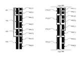
- FIG. 5Billustrates two columns, or four unit cells, of a sensor array pattern similar to the sensor array pattern 500 illustrated in FIG. 5A .
- Subelements 511 , 520 ( 1 ), and 521 ( 1 )are contained within the same unit cell.
- Subelements 512 , 520 ( 2 ), and 521 ( 2 )are contained within the same unit cell.
- Subelements 513 , 520 ( 3 ), and 521 ( 3 )are contained within the same unit cell.
- Subelements 514 , 520 ( 4 ), and 521 ( 4 )are contained within the same unit cell.
- Subelements 511 - 514are in the same column region from a first set of column regions and subelements 520 - 521 are in the same column region from a second set of column regions.
- the small subelements 520 ( 1 ) and 521 ( 1 ) within the same unit cell as large subelement 511may be arranged along an axis parallel to a longitudinal axis 511 a of the large subelement 511 .
- the large subelements 511 - 514are substantially equal to each other in size.
- the small subelements 520 - 521are substantially equal to each other in size.
- each of the large subelements 511 - 514is electrically isolated from each of the other subelements 511 - 514 that are in the same column region, or that are in a different row of the grid of N ⁇ M unit cells.
- each of the sensor electrodes including large subelementsmay also include a routing trace extending from the one or more of the large subelements to an edge of the surface area.
- each of the large subelements 511 , 512 , 513 , and 514may be electrically connected to routing traces 511 b , 512 b , 513 b , and 514 b , respectively, which extend towards the edge 504 of the capacitive sensor array where they can be connected to a capacitance sensor.
- each of the small subelements 520 - 521is electrically coupled via one or more connecting traces with at least another one of the small subelements 520 - 521 in a same column of the grid of N ⁇ M unit cells.
- connecting trace 521 belectrically connects small subelement 521 ( 1 ) with another small subelement 521 ( 2 ) in the same column region, but in a different row of unit cells.
- the small subelements within the same column regionmake up two sensor electrodes that have their respective subelements interleaved so that the subelements belonging to the electrodes alternate from one end of the column region to the opposite end.
- a small subelement that has its greatest capacitive coupling with a first large subelementmay be electrically connected via a connecting trace to a different small subelement that has its greatest capacitive coupling with a second large subelement.
- the small subelement 521 ( 1 )is closest to and has its greatest capacitive coupling with large subelement 511 ; subelement 521 is electrically connected via connecting trace 521 b to small subelement 521 ( 2 ), which is closest to and has its greatest capacitive coupling with large subelement 512 .
- a sensor electrodemay include a subelement in each row of unit cells.
- the small subelementsmake up two sensor electrodes; the subelements 520 are electrically coupled by conductive traces to form one sensor electrode, and the subelements 521 are electrically coupled by conductive traces to form another sensor electrode.
- each of the small subelements 520 - 521is wider than any of the one or more connecting traces between the small subelements.
- one or more of the sensor electrodes consisting of small subelementsmay be connected to a routing trace that extends towards an edge of the capacitive sensor array.
- the routing tracesmay thus extend from one or more of the small subelements to an edge of the surface area so that they can be connected to a capacitance sensor.
- routing trace 521is electrically connected to subelements 521 and extends from the subelements 521 toward an edge 504 of the capacitive sensor array.
- the ratio of sensing regions (N ⁇ k) to routing traces (N+k)is at least (N ⁇ k):(N+k) for a given column.
- FIG. 5Cillustrates an embodiment of a sensor array pattern where each of the large subelements is electrically coupled with at least another large subelement in the same column of the grid of N ⁇ M unit cells, and where each of the small subelements is electrically coupled with at least one other small subelement in a different unit cell.
- each of the large subelements 530 and 531is electrically connected via one or more conductive connecting traces to another of the large subelements.
- Subelement 530 ( 1 )is connected via a connecting trace 530 b to subelement 530 ( 2 ), which is in the same column as subelement 530 ( 1 ), but in a different unit cell in a different row of unit cells.
- subelement 531 ( 1 )is connected via a connecting trace 531 b to subelement 531 ( 2 ), which is in the same column as subelement 531 ( 1 ), but is in a different unit cell in a different row of unit cells.
- the large subelements within the same column regionmake up two sensor electrodes that have their respective subelements interleaved so that the subelements belonging to the electrodes alternate from one end of the column region to the opposite end.
- each of the small subelements 541 - 544may be electrically connected via one or more connecting traces to another small subelement in a different unit cell.
- small subelement 542 ( 1 )may be electrically connected via a connecting trace 542 b to small subelement 542 ( 2 ), which is in the same column and in a different unit cell and different row of unit cells.
- a small subelement that is capacitively coupled to a first large subelementmay be electrically connected to another small subelement that capacitively coupled with a second large subelement different from the first large subelement.
- small subelement 543 ( 1 )is closest to, and thus has its greatest capacitive coupling with, the large subelement 530 ( 2 ). Accordingly, small subelement 543 ( 1 ) is electrically coupled with small subelement 543 ( 2 ), which is closest to large subelement 531 ( 2 ).
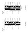
- FIG. 6Aillustrates a capacitive sensor array 600 , according to an embodiment.
- the sensor array 600includes a pattern of conductive material including similar features as the pattern 500 , as illustrated in FIG. 5A .
- the surface area of sensor array pattern 600is bounded by top, left, right, and bottom edges 610 , 611 , 612 , and 613 . In one embodiment, the surface area of the sensor array pattern is the active sensing area of the sensor array.
- the surface area of sensor array pattern 600may be divisible into alternating column regions. Specifically, a first set of column regions may include column regions 602 ( 1 ), 602 ( 2 ), 602 ( 3 ), 602 ( 4 ), 602 ( 5 ), and 602 ( 6 ), which are interleaved with a second set of column regions, including column regions 603 ( 1 ), 603 ( 2 ), 603 ( 3 ), 603 ( 4 ), 603 ( 5 ), and 603 ( 6 ).
- the column regions from the first set and second set of column regionsalternate along the length of a horizontal axis passing from edge 611 to 612 through the longitudinal axes of the column regions 602 and 603 .
- the large subelementsare located within first set of column regions 602
- the small subelementsare located within the second set of column regions 603 .
- each of the column regions 602 and 603extends from a first edge 610 to a second edge 613 of the surface area of sensor array 600 .
- the surface area of sensor array 600is substantially rectangular such that the first edge 610 is opposite the second edge 613 .
- the area of the sensor array 600may include routing channels 601 ( 1 ), 601 ( 2 ), 601 ( 3 ), 601 ( 4 ), 601 ( 5 ), and 601 ( 6 ), which contain the routing traces that are electrically connected to the subelements, and that extend from the subelements towards the edge 610 of the sensor array 600 .
- a sensing regionmay exist wherever a small subelement is near a large subelement; thus, as illustrated in FIG. 6A , sensor array 600 may have a resolution of 16 ⁇ 6 sensing regions.
- the surface area of sensor array 600may be divisible into a grid of 8 rows and 6 columns, where each unit cell includes two sensing regions.
- FIG. 6Billustrates electrical connections between the sensor array 600 and a capacitance sensor 101 , according to one embodiment.
- each of the sensor electrodes large subelementsmay be electrically connected to one of the row pins 101 a of the capacitance sensor 101 .
- each of the large subelements in the same row of unit cellsmay be connected to the same row pin, while each of the large subelements in the same column of unit cells may be connected to a different row pin.
- each of the sensor electrodes including small subelementsmay be connected to one of the column pins 101 b of capacitance sensor 101 .
- the large subelementsmay be electrically connected to column pins, while the small subelements are electrically connected to row pins.
- FIG. 7illustrates an embodiment of a sensor array 700 .
- the sensor array 700includes a pattern of conductive material similar to the pattern as illustrated in FIG. 5C .
- the surface area of sensor array pattern 700is bounded by top, left, right, and bottom edges 710 , 711 , 712 , and 713 . In one embodiment, the surface area of the sensor array pattern 700 is the active sensing area of the pattern 700 .
- the surface area of sensor array pattern 700may be divisible into alternating column regions. Specifically, a first set of column regions may include column regions 702 ( 1 ), 702 ( 2 ), 702 ( 3 ), and 702 ( 4 ), which are interleaved with a second set of column regions, including column regions 703 ( 1 ), 703 ( 2 ), 703 ( 3 ), and 703 ( 4 ).
- the column regions from the first set and second set of column regionsalternate along the length of a horizontal axis passing from edge 711 to 712 through the longitudinal axes of the column regions 702 and 703 .
- the large subelementsare located within first set of column regions 702
- the small subelementsare located within the second set of column regions 703 .
- the routing channels 701 ( 1 )- 701 ( 8 )are areas including the routing traces that are electrically connected to the small subelements are extend from the small subelements towards an edge 710 where they can be connected to a capacitance sensor.
- the large subelement 811is adjacent to the small subelements 821 ( 1 ), 822 ( 1 ), and 823 ( 1 ), such that three sensing regions are formed, between large subelement 811 and each of the small subelements 821 ( 1 ), 822 ( 1 ), and 823 ( 1 ).
- each unit cellcontains one large subelement and three small subelements; thus, each unit cell contains three sensing regions.
- the order of the small subelementsis the same within each unit cell. For example, within each unit cell, electrode 821 is at the top, electrode 822 is in the middle, and electrode 823 is at the bottom of the unit cell. In one embodiment, the small subelements are aligned vertically along an axis that is parallel to a longitudinal axis of the large subelements.
- FIG. 8Aalso illustrates the routing of connecting traces that electrically connect the small subelements.
- connecting traces and routing tracesmay connect to different sides of the small subelements.
- subelements of electrode 821are connected to traces on the left side
- subelements of electrode 822are connected to traces on both left and right sides
- subelements of electrode 823are connected to traces on the right side.
- each sensor electrodewhether consisting of large subelements or small subelements, is electrically coupled with a routing trace that extends to an edge 804 of the capacitive sensor array.
- each subelementis electrically connected to a routing trace that extends to an edge 805 of the capacitive sensor array and is also connected to a routing trace that extends to a bottom edge 806 of the capacitive sensor array.
- the edge 806is opposite the edge 805 .
- each electrodemay be routed via the routing traces to two opposite sides of the capacitive sensor array.
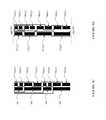
- FIGS. 9A, 9B, 9C, and 9Dillustrate embodiments of a single layer capacitive sensor array pattern that include electrodes comprising large subelements and electrodes comprising small subelements.
- electrodes corresponding to different rows or columnsmay have different shapes and/or dimensions. In one embodiment, this variation in subelement geometry may be used to compensate for signal non-uniformity across the sensor array.
- FIGS. 9A, 9B, 9C, and 9Dthus illustrate embodiments of pattern layouts having varied and fixed heights of sensor electrodes subelements.
- FIG. 9Aillustrates an embodiment of a sensor array pattern where subelements of the same electrode may be substantially the same size, but subelements of different electrodes may be different sizes.
- the subelements 921 ( 1 ), 921 ( 2 ), 921 ( 3 ), and 921 ( 4 ), which are electrically coupled together as part of the same electrode,are similar in size to each other; however, these subelements may each be smaller in size than any of subelements 922 ( 1 ), 922 ( 2 ), 922 ( 3 ), or 922 ( 4 ).
- the combined area of the small subelements paired with a large subelement in the same unit cellmay be less than the area of the large subelement.
- the combined area of small subelements 921 ( 1 ) and 922 ( 1 )may be less than or equal to the area of the large subelement 910 .
- the large subelements 911 , 912 , 913 , and 914may be similar in size, and may each be larger than any of the subelements of electrodes 921 or 922 .
- FIG. 9Billustrates an embodiment of a sensor array pattern where subelements of the same electrode may be different sizes.
- each electrodemay have two small electrodes, one of which is smaller than the other.
- the electrode 941may have two small subelements 941 ( 1 ) and 941 ( 2 ), where subelement 941 ( 1 ) is smaller than subelement 941 ( 2 ).
- electrode 942has two small subelements 942 ( 1 ) and 942 ( 2 ), where subelement 942 ( 2 ) is smaller than subelement 942 ( 1 ); electrode 943 has two small subelements 943 ( 1 ) and 943 ( 2 ), where subelement 943 ( 1 ) is smaller than subelement 942 ( 2 ); and electrode 944 has two small subelements 944 ( 1 ) and 944 ( 2 ), where subelement 944 ( 2 ) is smaller than subelement 944 ( 1 ).
- the subelements of sensor electrode 941may be interleaved with the subelements of sensor electrode 942
- the subelements of sensor electrode 943may be interleaved with the subelements of sensor electrode 944 .
- FIG. 9Cillustrates an embodiment of a sensor array pattern where the heights of both the large subelements and the small subelements are varied.
- each of the large subelements 951 , 952 , 953 , and 954may be electrically isolated from each other and may have alternating sizes.
- subelements 951 and 953are similar in size
- subelements 952 and 954are similar in size and are each larger than either of subelements 951 and 953 .
- each of the large subelementsis larger than either of the small subelements with which the large subelement is paired; however, in one embodiment, a “large” subelement may be smaller than a “small” subelement in a different row.
- subelement 951has a larger area than either of the small subelements 961 ( 1 ) and 962 ( 1 ), but may be smaller than subelement 961 ( 2 ).
- the sensor electrode 961includes small subelements 961 ( 1 ), 961 ( 2 ), 961 ( 3 ), and 961 ( 4 ). Of these subelements, subelements 961 ( 1 ) and 961 ( 3 ) are similar in size, and subelements 961 ( 2 ) and 961 ( 4 ) are similar in size and are each larger than either of subelements 961 ( 1 ) and 961 ( 3 ).
- Sensor electrode 962includes small subelements 962 ( 1 ), 962 ( 2 ), 962 ( 3 ), and 962 ( 4 ).
- subelements 962 ( 1 ) and 962 ( 3 )are similar in size, and subelements 962 ( 2 ) and 962 ( 4 ) are similar in size and are each larger than either of subelements 962 ( 1 ) and 962 ( 3 ).
- the subelements of sensor electrode 961may be interleaved with the subelements of sensor electrode 962 .
- FIG. 9Dillustrates an embodiment of a single layer sensor pattern having large and small sensor electrode subelements where the subelements vary in size progressively from one side of the sensor array area to another.
- the large subelements 971 ( 1 ), 972 ( 1 ), 971 ( 2 ), and 972 ( 2 )may become progressively larger the farther they are from edge 905 and the nearer they are to an opposite edge 906 .
- each of the small subelements 981 ( 1 ), 982 ( 1 ), 981 ( 2 ), 982 ( 2 ), 983 ( 1 ), 984 ( 1 ), 983 ( 2 ), and 984 ( 2 )may become progressively larger they farther they are from edge 905 and the nearer they are to edge 906 .
- the subelements 981 ( 1 ) and 981 ( 2 ) of sensor electrode 981may be interleaved with the subelements 982 ( 1 ) and 982 ( 2 ) of sensor electrode 982 .
- the subelements 983 ( 1 ) and 983 ( 2 ) of sensor electrode 983may be interleaved with the subelements 984 ( 1 ) and 984 ( 2 ) of sensor electrode 984 .
- FIG. 10Aillustrates an embodiment of a sensor array 1000 having a pattern similar to the pattern as illustrated in FIG. 5B .
- sensor array 1000includes a number of routing traces, such as routing traces 1010 , that are electrically connected to the sensor electrodes in sensor array 1000 and extend towards an edge of the sensor array 1000 .
- the routing traces 1010may connect the sensor electrodes to pins outside of the active sensing area. In one embodiment, the pins may be hidden by an opaque top bezel.
- the sensor electrodes in the array 1000may be connected to circuitry on a PCB 1003 via a connector 1002 .
- the connector 1002may be made from conductive material on a flexible substrate.
- components of the capacitance sensing system, such as the processing device 110may be mounted on the PCB 1003 .
- other hardwaresuch as hardware supporting a display over which the sensor array is overlaid, may also be mounted on PCB 1003 .
- one or more of the sensor electrodes in array 1000may be connected together; for example, each of the sensor electrodes including large subelements that are in the same row of unit cells may be electrically coupled together and sensed together.
- some or all of the connections between sensor electrodesmay be established by one or more switches, multiplexers, conductive traces, or other conductive paths that may reside on or underneath the bezel 1001 , on the PCB 1003 , or on some other part of the sensor array assembly.
- FIG. 10Billustrates an embodiment of a sensor array 1050 having a sensor pattern that is similar to the pattern of sensor array 1000 , but for the routing traces, such as routing traces 1060 and 1061 , that lead in opposite directions to a top bezel 1051 and a bottom bezel 1052 , respectively.
- routing traces that are electrically connected to a particular subelementextend towards the one of two opposite edges of the sensor array that is nearer to the particular subelement in order to minimize the length of the routing trace.
- the large subelements nearest the top bezel 1051are connected to routing traces that extend towards the top bezel 1051
- the large subelements nearest the bottom bezelare connected to routing traces that extend toward the bottom bezel 1052 .
- the sensor electrodes in the array 1050may be connected to circuitry on a PCB 1055 via connectors 1053 and 1054 .
- one or both of the connectors 1053 and 1054may be made from conductive material on a flexible substrate.
- components of the capacitance sensing system, such as the processing device 110may be mounted on the PCB 1055 .
- other hardwaresuch as hardware supporting a display over which the sensor array is overlaid, may also be mounted on PCB 1055 .
- one or more of the sensor electrodes in array 1050may be connected together; for example, each of the sensor electrodes including large subelements that are in the same row of unit cells may be electrically coupled together and sensed together.
- some or all of the connections between sensor electrodesmay be established by one or more switches, multiplexers, conductive traces, or other conductive paths that may reside on or underneath one or both of the bezels 1051 and 1052 , on the PCB 1055 , or on some other part of the sensor array assembly.
- row sensor electrodes and column sensor electrodesmay be interchanged, and row or column sensor electrodes may be used as either TX or RX sensor electrodes.
- sensor electrodes comprising large subelementsmay be used as TX or RX sensor electrodes and sensor electrodes comprising small subelements may be used as RX or TX sensor electrodes.
- intersections between row and column sensor electrodesmay be replaced with conductive bridges.
- bridgesmay be used to electrically connect portions of sensor electrodes when both row and column sensor electrodes are constructed from a single layer of conductive material.
- conductive electrodes that are “electrically connected” or “electrically coupled”may be coupled such that a relatively low resistance conductive path exists between the conductive electrodes.
- Embodiments of the present inventioninclude various operations. These operations may be performed by hardware components, software, firmware, or a combination thereof.
- the term “coupled to”may mean coupled directly or indirectly through one or more intervening components. Any of the signals provided over various buses described herein may be time multiplexed with other signals and provided over one or more common buses. Additionally, the interconnection between circuit components or blocks may be shown as buses or as single signal lines. Each of the buses may alternatively be one or more single signal lines and each of the single signal lines may alternatively be buses.
- Certain embodimentsmay be implemented as a computer program product that may include instructions stored on a computer-readable medium. These instructions may be used to program a general-purpose or special-purpose processor to perform the described operations.
- a computer-readable mediumincludes any mechanism for storing or transmitting information in a form (e.g., software, processing application) readable by a machine (e.g., a computer).
- the computer-readable storage mediummay include, but is not limited to, magnetic storage medium (e.g., floppy diskette); optical storage medium (e.g., CD-ROM); magneto-optical storage medium; read-only memory (ROM); random-access memory (RAM); erasable programmable memory (e.g., EPROM and EEPROM); flash memory, or another type of medium suitable for storing electronic instructions.
- magnetic storage mediume.g., floppy diskette
- optical storage mediume.g., CD-ROM
- magneto-optical storage mediume.g., magneto-optical storage medium
- ROMread-only memory
- RAMrandom-access memory
- EPROM and EEPROMerasable programmable memory
- flash memoryor another type of medium suitable for storing electronic instructions.
- some embodimentsmay be practiced in distributed computing environments where the computer-readable medium is stored on and/or executed by more than one computer system.
- the information transferred between computer systemsmay either be pulled or pushed across the transmission medium connecting the computer systems.
Landscapes
- Engineering & Computer Science (AREA)
- General Engineering & Computer Science (AREA)
- Theoretical Computer Science (AREA)
- Human Computer Interaction (AREA)
- Physics & Mathematics (AREA)
- General Physics & Mathematics (AREA)
- Position Input By Displaying (AREA)
- Measurement Of Length, Angles, Or The Like Using Electric Or Magnetic Means (AREA)
Abstract
Description
Claims (20)
Priority Applications (3)
| Application Number | Priority Date | Filing Date | Title |
|---|---|---|---|
| US13/904,481US9292138B2 (en) | 2013-02-08 | 2013-05-29 | Single layer sensor pattern |
| CN201480020107.0ACN105637458B (en) | 2013-02-08 | 2014-01-15 | Single layer sensor pattern |
| PCT/US2014/011644WO2014123671A1 (en) | 2013-02-08 | 2014-01-15 | Single layer sensor pattern |
Applications Claiming Priority (2)
| Application Number | Priority Date | Filing Date | Title |
|---|---|---|---|
| US201361762550P | 2013-02-08 | 2013-02-08 | |
| US13/904,481US9292138B2 (en) | 2013-02-08 | 2013-05-29 | Single layer sensor pattern |
Publications (2)
| Publication Number | Publication Date |
|---|---|
| US20160004343A1 US20160004343A1 (en) | 2016-01-07 |
| US9292138B2true US9292138B2 (en) | 2016-03-22 |
Family
ID=51300041
Family Applications (1)
| Application Number | Title | Priority Date | Filing Date |
|---|---|---|---|
| US13/904,481ActiveUS9292138B2 (en) | 2013-02-08 | 2013-05-29 | Single layer sensor pattern |
Country Status (3)
| Country | Link |
|---|---|
| US (1) | US9292138B2 (en) |
| CN (1) | CN105637458B (en) |
| WO (1) | WO2014123671A1 (en) |
Cited By (11)
| Publication number | Priority date | Publication date | Assignee | Title |
|---|---|---|---|---|
| US20150008941A1 (en)* | 2013-03-11 | 2015-01-08 | Cypress Semiconductor Corporation | Flipped Cell Sensor Pattern |
| US20150193047A1 (en)* | 2013-09-10 | 2015-07-09 | Cypress Semiconductor Corporation | Interleaving sense elements of a capacitive-sense array |
| US20160154517A1 (en)* | 2013-05-06 | 2016-06-02 | Polyic Gmbh & Co. Kg | Layer Electrode for Touchscreens |
| US20170060322A1 (en)* | 2014-03-03 | 2017-03-02 | Nokia Technologies Oy | Capacitive Touch Sensor Circuit, Method of Forming Circuit, and Touch Screen and Mobile Device Comprising the Same |
| US9612265B1 (en) | 2011-09-23 | 2017-04-04 | Cypress Semiconductor Corporation | Methods and apparatus to detect a conductive object |
| US20170160833A1 (en)* | 2014-06-23 | 2017-06-08 | Leading Ui Co., Ltd. | Capacitive touch panel and capacitive touch apparatus having the same |
| US20190235678A1 (en)* | 2018-01-31 | 2019-08-01 | Samsung Display Co., Ltd. | Display device |
| US10372258B2 (en)* | 2015-12-31 | 2019-08-06 | Xiamen Tianma Micro-Electronics Co., Ltd. | Touch-control display device |
| US20200183516A1 (en)* | 2014-03-14 | 2020-06-11 | Samsung Display Co., Ltd. | Touch panel and display device including the same |
| US10963084B2 (en)* | 2019-04-02 | 2021-03-30 | Samsung Display Co., Ltd. | Touch sensor |
| US20220179324A1 (en)* | 2019-03-21 | 2022-06-09 | Dongwoo Fine-Chem Co., Ltd. | Touch sensor and exposure mask for forming same |
Families Citing this family (12)
| Publication number | Priority date | Publication date | Assignee | Title |
|---|---|---|---|---|
| KR102291564B1 (en)* | 2015-01-06 | 2021-08-19 | 삼성디스플레이 주식회사 | Touch panel comprising touch sensor and diriving method thereof |
| US10152163B2 (en)* | 2015-03-10 | 2018-12-11 | Cirque Corporation | Method of reducing the space occupied by electrode routing traces on single layer touch sensor |
| CN104765499A (en)* | 2015-04-15 | 2015-07-08 | 合肥京东方光电科技有限公司 | Touch screen and touch device |
| KR102402256B1 (en)* | 2015-11-04 | 2022-05-27 | 삼성디스플레이 주식회사 | Display device |
| CN105677094B (en)* | 2016-01-04 | 2018-10-09 | 京东方科技集团股份有限公司 | Touch panel, point detecting method of touch control and display device |
| TWI581157B (en)* | 2016-04-20 | 2017-05-01 | 群創光電股份有限公司 | Touch display device |
| CN106502484B (en)* | 2016-11-04 | 2019-05-21 | 友达光电(苏州)有限公司 | touch unit |
| KR102205762B1 (en)* | 2017-04-11 | 2021-01-21 | 주식회사 지2터치 | Touch screen |
| KR102461720B1 (en)* | 2017-08-03 | 2022-11-01 | 삼성전자주식회사 | Fingerprint recongnizing sensor and combined fingerprint recognition touch screen device |
| US11256359B2 (en)* | 2019-03-29 | 2022-02-22 | Mianyang Boe Optoelectronics Technology Co., Ltd. | Touch screen, touch display screen and display device |
| US10747384B1 (en)* | 2019-08-01 | 2020-08-18 | Stmicroelectronics Asia Pacific Pte Ltd | Single layer capacitive touch matrix |
| CN111427475B (en)* | 2020-03-26 | 2022-09-02 | 京东方科技集团股份有限公司 | Touch module, touch display screen and manufacturing method of touch display screen |
Citations (84)
| Publication number | Priority date | Publication date | Assignee | Title |
|---|---|---|---|---|
| US4123631A (en)* | 1977-02-16 | 1978-10-31 | Owens-Illinois, Inc. | Touch switch |
| US4233522A (en) | 1978-10-30 | 1980-11-11 | General Electric Company | Capacitive touch switch array |
| US4293987A (en)* | 1978-03-16 | 1981-10-13 | Texas Instruments Incorporated | Method of fabricating capacitive touch switch panel |
| US4379287A (en)* | 1978-08-08 | 1983-04-05 | Robertshaw Controls Company | Capacitive switch and panel |
| US4707845A (en) | 1986-08-26 | 1987-11-17 | Tektronix, Inc. | Touch panel with automatic nulling |
| US6452514B1 (en)* | 1999-01-26 | 2002-09-17 | Harald Philipp | Capacitive sensor and array |
| US6590629B1 (en) | 1999-02-05 | 2003-07-08 | Sharp Kabushiki Kaisha | Liquid crystal display having a plurality of mounting substrates with common connection lines connecting the mounting substrates |
| US20040175257A1 (en) | 2001-08-09 | 2004-09-09 | Dirk Pallas | Capacitive proximity sensor for detecting component belts, component feeding device and method for detecting component belts |
| US20040239650A1 (en) | 2003-06-02 | 2004-12-02 | Mackey Bob Lee | Sensor patterns for a capacitive sensing apparatus |
| US20050270273A1 (en) | 2003-06-13 | 2005-12-08 | Victor Marten | Sensor for capacitive touch pad pointing device |
| US20050280639A1 (en) | 2002-08-02 | 2005-12-22 | Cirque Corporation | Single-layer touchpad having touch zones |
| US20060097991A1 (en) | 2004-05-06 | 2006-05-11 | Apple Computer, Inc. | Multipoint touchscreen |
| US20070008299A1 (en) | 2005-07-08 | 2007-01-11 | Harald Philipp | Two-Dimensional Position Sensor |
| US20070074913A1 (en) | 2005-10-05 | 2007-04-05 | Geaghan Bernard O | Capacitive touch sensor with independently adjustable sense channels |
| US20070074914A1 (en) | 2005-10-05 | 2007-04-05 | Geaghan Bernard O | Interleaved electrodes for touch sensing |
| US7202859B1 (en) | 2002-08-09 | 2007-04-10 | Synaptics, Inc. | Capacitive sensing pattern |
| US7202855B2 (en) | 2001-09-20 | 2007-04-10 | Alps Electric Co., Ltd. | Capacitive input device |
| US20070279395A1 (en) | 2006-05-31 | 2007-12-06 | Harald Philipp | Two Dimensional Position Sensor |
| US20080006453A1 (en)* | 2006-07-06 | 2008-01-10 | Apple Computer, Inc., A California Corporation | Mutual capacitance touch sensing device |
| US7382139B2 (en) | 2004-06-03 | 2008-06-03 | Synaptics Incorporated | One layer capacitive sensing apparatus having varying width sensing elements |
| US20080143683A1 (en) | 2006-12-15 | 2008-06-19 | Apple Inc. | Pet-based touch pad |
| US20080158181A1 (en) | 2007-01-03 | 2008-07-03 | Apple Computer, Inc. | Double-sided touch sensitive panel and flex circuit bonding |
| US20080246496A1 (en) | 2007-04-05 | 2008-10-09 | Luben Hristov | Two-Dimensional Position Sensor |
| US7439962B2 (en) | 2005-06-01 | 2008-10-21 | Synaptics Incorporated | Touch pad with flexible substrate |
| US20080264699A1 (en) | 2007-04-27 | 2008-10-30 | Trendon Touch Technology Corp. | Conductor pattern structure of capacitive touch panel |
| US20080265914A1 (en)* | 2007-04-24 | 2008-10-30 | Kenichi Matsushima | Proximity detector and proximity detecting method |
| US7499039B2 (en) | 2005-01-10 | 2009-03-03 | 3M Innovative Properties Company | Iterative method for determining touch location |
| US20090090694A1 (en) | 2007-10-03 | 2009-04-09 | Apple Inc. | Shaping a cover glass |
| US20090159344A1 (en) | 2007-12-21 | 2009-06-25 | Apple Inc. | Touch pad electrode design |
| CN101470557A (en) | 2007-12-27 | 2009-07-01 | 统宝光电股份有限公司 | Position sensing panel, detection method and display |
| US20090273570A1 (en) | 2008-04-30 | 2009-11-05 | Apple Inc. | Multi-touch sensor patterns and stack-ups |
| US20090314621A1 (en)* | 2008-04-25 | 2009-12-24 | Apple Inc. | Brick Layout and Stackup for a Touch Screen |
| US7639234B2 (en) | 2007-01-04 | 2009-12-29 | Avago Technologies Ecbu Ip (Singapore) Pte. Ltd. | Capacitive sensing and absolute position mapping in displacement type pointing devices |
| US20100059294A1 (en)* | 2008-09-08 | 2010-03-11 | Apple Inc. | Bandwidth enhancement for a touch sensor panel |
| US20100079384A1 (en) | 2008-09-26 | 2010-04-01 | Cypress Semiconductor Corporation | Capacitance touch screen |
| US20100090979A1 (en)* | 2007-03-05 | 2010-04-15 | Melfas, Inc. | Touch location detecting panel having a simple layer structure |
| US20100108409A1 (en) | 2008-11-06 | 2010-05-06 | Jun Tanaka | Capacitive coupling type touch panel |
| US20100123670A1 (en) | 2008-11-15 | 2010-05-20 | Atmel Corporation | Touch Screen Sensor |
| US20100144391A1 (en) | 2008-12-05 | 2010-06-10 | Shih Chang Chang | Integrated touch panel for a TFT display |
| US20100149108A1 (en) | 2008-12-11 | 2010-06-17 | Steve Porter Hotelling | Single layer touch panel with segmented drive and sense electrodes |
| US20100201647A1 (en) | 2009-02-11 | 2010-08-12 | Tpo Displays Corp. | Capacitive touch sensor |
| US20100214247A1 (en) | 2009-02-20 | 2010-08-26 | Acrosense Technology Co., Ltd. | Capacitive Touch Panel |
| US20100214260A1 (en) | 2009-02-24 | 2010-08-26 | Jun Tanaka | Liquid crystal display device with input function |
| US20100220071A1 (en) | 2009-02-20 | 2010-09-02 | Kiyoshi Nishihara | Touch panel and display device including the same |
| JP2010205177A (en) | 2009-03-05 | 2010-09-16 | Sharp Corp | Screen board and method for manufacturing touch panel using same |
| US20100258360A1 (en)* | 2009-04-14 | 2010-10-14 | Atmel Corporation | Two-Dimensional Position Sensor |
| US7821425B2 (en) | 2002-07-12 | 2010-10-26 | Atmel Corporation | Capacitive keyboard with non-locking reduced keying ambiguity |
| US20100289774A1 (en) | 2009-05-15 | 2010-11-18 | Mstar Semiconductor, Inc. | Capacitive Touch Sensing Structure and Sensing Method Thereof |
| US20100321331A1 (en) | 2009-06-18 | 2010-12-23 | Wacom Co., Ltd. | Pointer detection apparatus and pointer detection method |
| US20100321326A1 (en)* | 2009-06-19 | 2010-12-23 | Grunthaner Martin Paul | Direct Connect Single Layer Touch Panel |
| US20110012845A1 (en) | 2009-07-20 | 2011-01-20 | Rothkopf Fletcher R | Touch sensor structures for displays |
| US20110048813A1 (en) | 2009-09-03 | 2011-03-03 | Esat Yilmaz | Two-dimensional position sensor |
| US20110048812A1 (en)* | 2009-09-03 | 2011-03-03 | Esat Yilmaz | Two-dimensional position sensor |
| US20110062969A1 (en)* | 2009-09-11 | 2011-03-17 | Kirk Hargreaves | Single layer capacitive image sensing |
| US20110062974A1 (en) | 2009-09-11 | 2011-03-17 | Day Shawn P | Input device based on voltage gradients |
| US20110102361A1 (en) | 2009-10-29 | 2011-05-05 | Atmel Corporation | Touchscreen electrode configuration |
| US20110148785A1 (en) | 2009-12-18 | 2011-06-23 | Wacom Co., Ltd. | Pointer detection apparatus and pointer detection method |
| US7973771B2 (en) | 2007-04-12 | 2011-07-05 | 3M Innovative Properties Company | Touch sensor with electrode array |
| US20110170099A1 (en) | 2010-01-11 | 2011-07-14 | Ko Cheng-Hao | Spectrometer capable of eliminating side-tail effects |
| US20110215814A1 (en) | 2010-03-04 | 2011-09-08 | Franklin Sensors Inc. | Advanced obscured feature detector |
| WO2011142589A2 (en) | 2010-05-11 | 2011-11-17 | Woo Gwan-Je | Pet touch sensor for a touch screen and a fabrication method of the sensor |
| US20110279169A1 (en)* | 2010-05-14 | 2011-11-17 | Salaverry Ricardo R | System and method for detecting locations of touches on a projected capacitive touch sensor |
| US8072429B2 (en) | 2006-12-22 | 2011-12-06 | Cypress Semiconductor Corporation | Multi-axial touch-sensor device with multi-touch resolution |
| US20120050180A1 (en) | 2010-08-27 | 2012-03-01 | Brian Michael King | Touch and hover switching |
| US8149207B2 (en) | 2008-07-09 | 2012-04-03 | Chi Hsin Electronics Corp. | Touch signal transmission circuit for touch LCD |
| DE202012101378U1 (en) | 2011-10-20 | 2012-04-27 | Atmel Corp. | One-layer touch sensor |
| US20120162090A1 (en) | 2010-12-22 | 2012-06-28 | Shih Chang Chang | Relay driving of displays |
| US20120162144A1 (en) | 2009-09-02 | 2012-06-28 | Flatfrog Laboratories Ab | Touch Surface With A Compensated Signal Profile |
| US8243027B2 (en) | 2006-06-09 | 2012-08-14 | Apple Inc. | Touch screen liquid crystal display |
| US20120227259A1 (en) | 2011-02-24 | 2012-09-13 | Cypress Semiconductor Corporation | Single layer touch sensor |
| US20120256851A1 (en) | 2011-04-08 | 2012-10-11 | Wintek Corporation | Touch panel and touch display panel |
| US20120262412A1 (en) | 2011-04-18 | 2012-10-18 | Guard David Brent | Touch Sensor with a Conductive Line Having Different Widths |
| US8300019B2 (en) | 2008-07-15 | 2012-10-30 | Apple Inc. | Capacitive sensor coupling correction |
| US20120306792A1 (en) | 2011-06-01 | 2012-12-06 | Powers Winston J | Touch Screen System |
| WO2012176639A1 (en) | 2011-06-22 | 2012-12-27 | Sharp Kabushiki Kaisha | Touch panel system and electronic device |
| US20130050105A1 (en) | 2011-08-23 | 2013-02-28 | Samsung Electro-Mechanics Co., Ltd. | Touch panel |
| US20130061869A1 (en)* | 2011-09-06 | 2013-03-14 | Brewer Science Inc. | Use of megasonic energy to assist edge bond removal in a zonal temporary bonding process |
| US20130081869A1 (en)* | 2011-09-30 | 2013-04-04 | Jae Hong Kim | Touch sensing apparatus and method of manufacturing the same |
| US20130100041A1 (en)* | 2011-10-21 | 2013-04-25 | Touch Turns Llc | System for a single-layer sensor having reduced number of interconnect pads for the interconnect periphery of the sensor panel |
| US20130127772A1 (en) | 2011-11-22 | 2013-05-23 | David Brent GUARD | Touch Sensor with Conductive Lines having Different Widths |
| US20130234974A1 (en) | 2012-03-06 | 2013-09-12 | David Brent GUARD | Touch Sensor with Conductive Lines Having Portions with Different Widths |
| US20140092036A1 (en) | 2012-10-03 | 2014-04-03 | Giantplus Technology Co., Ltd. | Touch panel with single electrode layer |
| US8754662B1 (en) | 2013-03-11 | 2014-06-17 | Cypress Semiconductor Corporation | Flipped cell sensor pattern |
| US20140210784A1 (en) | 2011-02-24 | 2014-07-31 | Cypress Semiconductor Corporation | Touch sensor device |
Family Cites Families (1)
| Publication number | Priority date | Publication date | Assignee | Title |
|---|---|---|---|---|
| CN102667693B (en)* | 2010-08-09 | 2016-07-06 | 创造者科技有限公司 | Mesh structure for applications related to capacitive sensing electrodes |
- 2013
- 2013-05-29USUS13/904,481patent/US9292138B2/enactiveActive
- 2014
- 2014-01-15CNCN201480020107.0Apatent/CN105637458B/enactiveActive
- 2014-01-15WOPCT/US2014/011644patent/WO2014123671A1/enactiveApplication Filing
Patent Citations (95)
| Publication number | Priority date | Publication date | Assignee | Title |
|---|---|---|---|---|
| US4123631A (en)* | 1977-02-16 | 1978-10-31 | Owens-Illinois, Inc. | Touch switch |
| US4293987A (en)* | 1978-03-16 | 1981-10-13 | Texas Instruments Incorporated | Method of fabricating capacitive touch switch panel |
| US4379287A (en)* | 1978-08-08 | 1983-04-05 | Robertshaw Controls Company | Capacitive switch and panel |
| US4233522A (en) | 1978-10-30 | 1980-11-11 | General Electric Company | Capacitive touch switch array |
| US4707845A (en) | 1986-08-26 | 1987-11-17 | Tektronix, Inc. | Touch panel with automatic nulling |
| US6452514B1 (en)* | 1999-01-26 | 2002-09-17 | Harald Philipp | Capacitive sensor and array |
| US6590629B1 (en) | 1999-02-05 | 2003-07-08 | Sharp Kabushiki Kaisha | Liquid crystal display having a plurality of mounting substrates with common connection lines connecting the mounting substrates |
| US20040175257A1 (en) | 2001-08-09 | 2004-09-09 | Dirk Pallas | Capacitive proximity sensor for detecting component belts, component feeding device and method for detecting component belts |
| US7202855B2 (en) | 2001-09-20 | 2007-04-10 | Alps Electric Co., Ltd. | Capacitive input device |
| US7821425B2 (en) | 2002-07-12 | 2010-10-26 | Atmel Corporation | Capacitive keyboard with non-locking reduced keying ambiguity |
| US20050280639A1 (en) | 2002-08-02 | 2005-12-22 | Cirque Corporation | Single-layer touchpad having touch zones |
| US7423635B2 (en) | 2002-08-02 | 2008-09-09 | Cirque Corporation | Single-layer touchpad having touch zones |
| US7202859B1 (en) | 2002-08-09 | 2007-04-10 | Synaptics, Inc. | Capacitive sensing pattern |
| US20040239650A1 (en) | 2003-06-02 | 2004-12-02 | Mackey Bob Lee | Sensor patterns for a capacitive sensing apparatus |
| US7129935B2 (en) | 2003-06-02 | 2006-10-31 | Synaptics Incorporated | Sensor patterns for a capacitive sensing apparatus |
| US20050270273A1 (en) | 2003-06-13 | 2005-12-08 | Victor Marten | Sensor for capacitive touch pad pointing device |
| US20060097991A1 (en) | 2004-05-06 | 2006-05-11 | Apple Computer, Inc. | Multipoint touchscreen |
| US7382139B2 (en) | 2004-06-03 | 2008-06-03 | Synaptics Incorporated | One layer capacitive sensing apparatus having varying width sensing elements |
| US7499039B2 (en) | 2005-01-10 | 2009-03-03 | 3M Innovative Properties Company | Iterative method for determining touch location |
| US7439962B2 (en) | 2005-06-01 | 2008-10-21 | Synaptics Incorporated | Touch pad with flexible substrate |
| US20110018841A1 (en) | 2005-07-08 | 2011-01-27 | Atmel Uk | Two-Dimensional Position Sensor |
| US20070008299A1 (en) | 2005-07-08 | 2007-01-11 | Harald Philipp | Two-Dimensional Position Sensor |
| US20070074914A1 (en) | 2005-10-05 | 2007-04-05 | Geaghan Bernard O | Interleaved electrodes for touch sensing |
| US20070074913A1 (en) | 2005-10-05 | 2007-04-05 | Geaghan Bernard O | Capacitive touch sensor with independently adjustable sense channels |
| US20070279395A1 (en) | 2006-05-31 | 2007-12-06 | Harald Philipp | Two Dimensional Position Sensor |
| US8243027B2 (en) | 2006-06-09 | 2012-08-14 | Apple Inc. | Touch screen liquid crystal display |
| US20080006453A1 (en)* | 2006-07-06 | 2008-01-10 | Apple Computer, Inc., A California Corporation | Mutual capacitance touch sensing device |
| US20080143683A1 (en) | 2006-12-15 | 2008-06-19 | Apple Inc. | Pet-based touch pad |
| CN101578574B (en) | 2006-12-15 | 2012-07-18 | 苹果公司 | PET based touchpad |
| US8072429B2 (en) | 2006-12-22 | 2011-12-06 | Cypress Semiconductor Corporation | Multi-axial touch-sensor device with multi-touch resolution |
| US20080158181A1 (en) | 2007-01-03 | 2008-07-03 | Apple Computer, Inc. | Double-sided touch sensitive panel and flex circuit bonding |
| US7639234B2 (en) | 2007-01-04 | 2009-12-29 | Avago Technologies Ecbu Ip (Singapore) Pte. Ltd. | Capacitive sensing and absolute position mapping in displacement type pointing devices |
| US8274488B2 (en) | 2007-03-05 | 2012-09-25 | Melfas, Inc. | Touch location detecting panel having a simple layer structure |
| US20100090979A1 (en)* | 2007-03-05 | 2010-04-15 | Melfas, Inc. | Touch location detecting panel having a simple layer structure |
| US20080246496A1 (en) | 2007-04-05 | 2008-10-09 | Luben Hristov | Two-Dimensional Position Sensor |
| US7973771B2 (en) | 2007-04-12 | 2011-07-05 | 3M Innovative Properties Company | Touch sensor with electrode array |
| US20080265914A1 (en)* | 2007-04-24 | 2008-10-30 | Kenichi Matsushima | Proximity detector and proximity detecting method |
| US20080264699A1 (en) | 2007-04-27 | 2008-10-30 | Trendon Touch Technology Corp. | Conductor pattern structure of capacitive touch panel |
| US20090090694A1 (en) | 2007-10-03 | 2009-04-09 | Apple Inc. | Shaping a cover glass |
| US20090159344A1 (en) | 2007-12-21 | 2009-06-25 | Apple Inc. | Touch pad electrode design |
| CN101470557A (en) | 2007-12-27 | 2009-07-01 | 统宝光电股份有限公司 | Position sensing panel, detection method and display |
| US20090314621A1 (en)* | 2008-04-25 | 2009-12-24 | Apple Inc. | Brick Layout and Stackup for a Touch Screen |
| US20090273570A1 (en) | 2008-04-30 | 2009-11-05 | Apple Inc. | Multi-touch sensor patterns and stack-ups |
| US8149207B2 (en) | 2008-07-09 | 2012-04-03 | Chi Hsin Electronics Corp. | Touch signal transmission circuit for touch LCD |
| US8300019B2 (en) | 2008-07-15 | 2012-10-30 | Apple Inc. | Capacitive sensor coupling correction |
| US20100059294A1 (en)* | 2008-09-08 | 2010-03-11 | Apple Inc. | Bandwidth enhancement for a touch sensor panel |
| US20100079384A1 (en) | 2008-09-26 | 2010-04-01 | Cypress Semiconductor Corporation | Capacitance touch screen |
| US20100108409A1 (en) | 2008-11-06 | 2010-05-06 | Jun Tanaka | Capacitive coupling type touch panel |
| US20100123670A1 (en) | 2008-11-15 | 2010-05-20 | Atmel Corporation | Touch Screen Sensor |
| US20100144391A1 (en) | 2008-12-05 | 2010-06-10 | Shih Chang Chang | Integrated touch panel for a TFT display |
| US20100149108A1 (en) | 2008-12-11 | 2010-06-17 | Steve Porter Hotelling | Single layer touch panel with segmented drive and sense electrodes |
| US8319747B2 (en) | 2008-12-11 | 2012-11-27 | Apple Inc. | Single layer touch panel with segmented drive and sense electrodes |
| US20100201647A1 (en) | 2009-02-11 | 2010-08-12 | Tpo Displays Corp. | Capacitive touch sensor |
| US20100220071A1 (en) | 2009-02-20 | 2010-09-02 | Kiyoshi Nishihara | Touch panel and display device including the same |
| US20100214247A1 (en) | 2009-02-20 | 2010-08-26 | Acrosense Technology Co., Ltd. | Capacitive Touch Panel |
| US20100214260A1 (en) | 2009-02-24 | 2010-08-26 | Jun Tanaka | Liquid crystal display device with input function |
| JP2010205177A (en) | 2009-03-05 | 2010-09-16 | Sharp Corp | Screen board and method for manufacturing touch panel using same |
| US20100258360A1 (en)* | 2009-04-14 | 2010-10-14 | Atmel Corporation | Two-Dimensional Position Sensor |
| US20100289774A1 (en) | 2009-05-15 | 2010-11-18 | Mstar Semiconductor, Inc. | Capacitive Touch Sensing Structure and Sensing Method Thereof |
| US20100321331A1 (en) | 2009-06-18 | 2010-12-23 | Wacom Co., Ltd. | Pointer detection apparatus and pointer detection method |
| US20100321326A1 (en)* | 2009-06-19 | 2010-12-23 | Grunthaner Martin Paul | Direct Connect Single Layer Touch Panel |
| US20110012845A1 (en) | 2009-07-20 | 2011-01-20 | Rothkopf Fletcher R | Touch sensor structures for displays |
| US20120162144A1 (en) | 2009-09-02 | 2012-06-28 | Flatfrog Laboratories Ab | Touch Surface With A Compensated Signal Profile |
| US20110048813A1 (en) | 2009-09-03 | 2011-03-03 | Esat Yilmaz | Two-dimensional position sensor |
| US20110048812A1 (en)* | 2009-09-03 | 2011-03-03 | Esat Yilmaz | Two-dimensional position sensor |
| US20110062969A1 (en)* | 2009-09-11 | 2011-03-17 | Kirk Hargreaves | Single layer capacitive image sensing |
| US20110062974A1 (en) | 2009-09-11 | 2011-03-17 | Day Shawn P | Input device based on voltage gradients |
| US8599150B2 (en) | 2009-10-29 | 2013-12-03 | Atmel Corporation | Touchscreen electrode configuration |
| US20120081324A1 (en) | 2009-10-29 | 2012-04-05 | Harald Philipp | Single-Layer Sensor Stack |
| US20130100054A1 (en) | 2009-10-29 | 2013-04-25 | Harald Philipp | Dual-Substrate-Sensor Stack With Electrodes Opposing a Display |
| US20110102361A1 (en) | 2009-10-29 | 2011-05-05 | Atmel Corporation | Touchscreen electrode configuration |
| US20110148785A1 (en) | 2009-12-18 | 2011-06-23 | Wacom Co., Ltd. | Pointer detection apparatus and pointer detection method |
| US20110170099A1 (en) | 2010-01-11 | 2011-07-14 | Ko Cheng-Hao | Spectrometer capable of eliminating side-tail effects |
| US20110215814A1 (en) | 2010-03-04 | 2011-09-08 | Franklin Sensors Inc. | Advanced obscured feature detector |
| WO2011142589A2 (en) | 2010-05-11 | 2011-11-17 | Woo Gwan-Je | Pet touch sensor for a touch screen and a fabrication method of the sensor |
| US20110279169A1 (en)* | 2010-05-14 | 2011-11-17 | Salaverry Ricardo R | System and method for detecting locations of touches on a projected capacitive touch sensor |
| US20120050180A1 (en) | 2010-08-27 | 2012-03-01 | Brian Michael King | Touch and hover switching |
| US20120162090A1 (en) | 2010-12-22 | 2012-06-28 | Shih Chang Chang | Relay driving of displays |
| US20120255167A1 (en) | 2011-02-24 | 2012-10-11 | Cypress Semiconductor Corporation | Single layer touch sensor |
| US20120227259A1 (en) | 2011-02-24 | 2012-09-13 | Cypress Semiconductor Corporation | Single layer touch sensor |
| US20120256642A1 (en) | 2011-02-24 | 2012-10-11 | Cypress Semiconductor Corporation | Single layer touch sensor |
| US20140210784A1 (en) | 2011-02-24 | 2014-07-31 | Cypress Semiconductor Corporation | Touch sensor device |
| US20120256851A1 (en) | 2011-04-08 | 2012-10-11 | Wintek Corporation | Touch panel and touch display panel |
| US20120262412A1 (en) | 2011-04-18 | 2012-10-18 | Guard David Brent | Touch Sensor with a Conductive Line Having Different Widths |
| US20120306792A1 (en) | 2011-06-01 | 2012-12-06 | Powers Winston J | Touch Screen System |
| WO2012176639A1 (en) | 2011-06-22 | 2012-12-27 | Sharp Kabushiki Kaisha | Touch panel system and electronic device |
| US20130050105A1 (en) | 2011-08-23 | 2013-02-28 | Samsung Electro-Mechanics Co., Ltd. | Touch panel |
| US20130061869A1 (en)* | 2011-09-06 | 2013-03-14 | Brewer Science Inc. | Use of megasonic energy to assist edge bond removal in a zonal temporary bonding process |
| US20130081869A1 (en)* | 2011-09-30 | 2013-04-04 | Jae Hong Kim | Touch sensing apparatus and method of manufacturing the same |
| DE202012101378U1 (en) | 2011-10-20 | 2012-04-27 | Atmel Corp. | One-layer touch sensor |
| US20130100041A1 (en)* | 2011-10-21 | 2013-04-25 | Touch Turns Llc | System for a single-layer sensor having reduced number of interconnect pads for the interconnect periphery of the sensor panel |
| US20130127772A1 (en) | 2011-11-22 | 2013-05-23 | David Brent GUARD | Touch Sensor with Conductive Lines having Different Widths |
| US20130234974A1 (en) | 2012-03-06 | 2013-09-12 | David Brent GUARD | Touch Sensor with Conductive Lines Having Portions with Different Widths |
| US20140092036A1 (en) | 2012-10-03 | 2014-04-03 | Giantplus Technology Co., Ltd. | Touch panel with single electrode layer |
| US8754662B1 (en) | 2013-03-11 | 2014-06-17 | Cypress Semiconductor Corporation | Flipped cell sensor pattern |
Non-Patent Citations (39)
| Title |
|---|
| "Chapter A: Wire Bonding" <www.vps.nu/img/image/Docs/safe%20light.pdf> Jun. 4, 1999 (Accessed Jun. 11, 2013). |
| "Chapter A: Wire Bonding" Jun. 4, 1999 (Accessed Jun. 11, 2013). |
| Ho, Tsz-Kin, et al. "32.3: Simple Single-Layer Multi-Touch Projected Capacitive Touch Panel." SID Symposium Digest of Technical Papers. vol. 40. No. 1. Blackwell Publishing Ltd, 2009. |
| International Search Report for International Application No. PCT/US11/53916 dated Apr. 10, 2012; 3 pages. |
| International Search Report for International Application No. PCT/US12/26634 dated May 29, 2012; 2 pages. |
| International Search Report for International Application No. PCT/US14/11644 dated Jun. 23, 2014; 2 pages. |
| International Search Report for International Application No. PCT/US14/16781 dated May 16, 2014; 2 pages. |
| International Search Report for International Application No. PCT/US14/51363 dated Dec. 18, 2014; 2 pages. |
| SIPO Office Action for Chinese Application No. 201280001803.8 dated Jan. 6, 2015; 6 pages. |
| U.S. Appl. No. 13/248,776: "Single Layer Touch Sensor," Massoud Badaye, filed Sep. 29, 2011; 36 pages. |
| USPTO Advisory Action for U.S. Appl. No. 13/405,071 dated Jan. 9, 2015; 3 pages. |
| USPTO Advisory Action for U.S. Appl. No. 14/229,524 dated Dec. 31, 2014; 3 pages. |
| USPTO Advisory Action for U.S. Appl. No. 14/318,354 dated Mar. 13, 2015; 3 pages. |
| USPTO Final Rejection for U.S. Appl. No. 13/405,071 dated Oct. 16, 2014; 18 pages. |
| USPTO Final Rejection for U.S. Appl. No. 13/918,252 dated Dec. 10, 2013; 16 pages. |
| USPTO Final Rejection for U.S. Appl. No. 14/229,524 dated Oct. 23, 2014; 16 pages. |
| USPTO Final Rejection for U.S. Appl. No. 14/318,354 dated Dec. 26, 2014; 19 pages. |
| USPTO Non-Final Rejection for U.S. Appl. No. 13/405,071 dated Apr. 30, 2015; 19 pages. |
| USPTO Non-Final Rejection for U.S. Appl. No. 13/405,071 dated Jul. 21, 2014; 15 pages. |
| USPTO Non-Final Rejection for U.S. Appl. No. 13/528,644 dated Nov. 20, 2012; 6 pages. |
| USPTO Non-Final Rejection for U.S. Appl. No. 13/528,739 dated Apr. 29, 2015; 19 pages. |
| USPTO Non-Final Rejection for U.S. Appl. No. 13/918,252 dated Sep. 20, 2013; 12 pages. |
| USPTO Non-Final Rejection for U.S. Appl. No. 14/229,524 dated Jul. 29, 2014; 15 pages. |
| USPTO Non-Final Rejection for U.S. Appl. No. 14/229,524 dated May 28, 2015; 16 pages. |
| USPTO Non-Final Rejection for U.S. Appl. No. 14/318,354 dated Jun. 10, 2015; 19 pages. |
| USPTO Non-Final Rejection for U.S. Appl. No. 14/318,354 dated Sep. 9, 2014; 18 pages. |
| USPTO Notice of Allowance for U.S. Appl. No. 13/528,644 dated Apr. 23, 2013; 6 pages. |
| USPTO Notice of Allowance for U.S. Appl. No. 13/528,644 dated Jan. 25, 2013; 5 pages. |
| USPTO Notice of Allowance for U.S. Appl. No. 13/528,664 dated Jun. 7, 2013; 3 pages. |
| USPTO Notice of Allowance for U.S. Appl. No. 13/918,252 dated Feb. 6, 2014; 8 pages. |
| USPTO Requirement for Restriction/Election for U.S. Appl. No. 14/229,524 dated Jun. 10, 2014; 6 pages. |
| USPTO Requirement to Restriction for U.S. Appl. No. 13/405,071 dated Sep. 13, 2013; 5 pages. |
| USPTO Requirement to Restriction for U.S. Appl. No. 13/528,644 dated Aug. 21, 2012; 6 pages. |
| Written Opinion and Search Report of the International Searching Authority for International Application No. PCT/US1411644 mailed Jun. 23, 2014; 11 pages. |
| Written Opinion of the International Searching Authority for International Application No. PCT/US11/53916 dated Apr. 10, 2012; 5 pages. |
| Written Opinion of the International Searching Authority for International Application No. PCT/US12/26634 mailed May 29, 2012; 5 pages. |
| Written Opinion of the International Searching Authority for International Application No. PCT/US14/11644 dated Jun. 23, 2014; 8 pages. |
| Written Opinion of the International Searching Authority for International Application No. PCT/US14/16781 mailed May 16, 2014; 6 pages. |
| Written Opinion of the International Searching Authority for International Application No. PCT/US14/51363 mailed Dec. 18, 2014; 7 pages. |
Cited By (19)
| Publication number | Priority date | Publication date | Assignee | Title |
|---|---|---|---|---|
| US9612265B1 (en) | 2011-09-23 | 2017-04-04 | Cypress Semiconductor Corporation | Methods and apparatus to detect a conductive object |
| US9547031B2 (en)* | 2013-03-11 | 2017-01-17 | Parade Technologies, Ltd. | Flipped cell sensor pattern |
| US20150008941A1 (en)* | 2013-03-11 | 2015-01-08 | Cypress Semiconductor Corporation | Flipped Cell Sensor Pattern |
| US9921698B2 (en)* | 2013-05-06 | 2018-03-20 | Polyic Gmbh & Co. Kg | Layer electrode for touchscreens |
| US20160154517A1 (en)* | 2013-05-06 | 2016-06-02 | Polyic Gmbh & Co. Kg | Layer Electrode for Touchscreens |
| US9563318B2 (en)* | 2013-09-10 | 2017-02-07 | Monterey Research, Llc | Interleaving conductive elements of a capacitive-sense array |
| US20150193047A1 (en)* | 2013-09-10 | 2015-07-09 | Cypress Semiconductor Corporation | Interleaving sense elements of a capacitive-sense array |
| US20170060322A1 (en)* | 2014-03-03 | 2017-03-02 | Nokia Technologies Oy | Capacitive Touch Sensor Circuit, Method of Forming Circuit, and Touch Screen and Mobile Device Comprising the Same |
| US12032775B2 (en)* | 2014-03-14 | 2024-07-09 | Samsung Display Co., Ltd. | Touch panel and display device including the same |
| US20200183516A1 (en)* | 2014-03-14 | 2020-06-11 | Samsung Display Co., Ltd. | Touch panel and display device including the same |
| US20170160833A1 (en)* | 2014-06-23 | 2017-06-08 | Leading Ui Co., Ltd. | Capacitive touch panel and capacitive touch apparatus having the same |
| US10372258B2 (en)* | 2015-12-31 | 2019-08-06 | Xiamen Tianma Micro-Electronics Co., Ltd. | Touch-control display device |
| US10775916B2 (en)* | 2018-01-31 | 2020-09-15 | Samsung Display Co., Ltd. | Display device including sensor electrodes |
| US11429211B2 (en) | 2018-01-31 | 2022-08-30 | Samsung Display Co., Ltd. | Display device |
| US20190235678A1 (en)* | 2018-01-31 | 2019-08-01 | Samsung Display Co., Ltd. | Display device |
| US20220179324A1 (en)* | 2019-03-21 | 2022-06-09 | Dongwoo Fine-Chem Co., Ltd. | Touch sensor and exposure mask for forming same |
| US11774858B2 (en)* | 2019-03-21 | 2023-10-03 | Dongwoo Fine-Chem Co., Ltd. | Touch sensor and exposure mask for forming same |
| US10963084B2 (en)* | 2019-04-02 | 2021-03-30 | Samsung Display Co., Ltd. | Touch sensor |
| US11340723B2 (en) | 2019-04-02 | 2022-05-24 | Samsung Display Co., Ltd. | Touch sensor |
Also Published As
| Publication number | Publication date |
|---|---|
| CN105637458A (en) | 2016-06-01 |
| CN105637458B (en) | 2018-11-16 |
| US20160004343A1 (en) | 2016-01-07 |
| WO2014123671A1 (en) | 2014-08-14 |
Similar Documents
| Publication | Publication Date | Title |
|---|---|---|
| US9292138B2 (en) | Single layer sensor pattern | |
| US9547031B2 (en) | Flipped cell sensor pattern | |
| US10402022B2 (en) | Sensor array with edge pattern | |
| US9513755B2 (en) | Lattice structure for capacitance sensing electrodes | |
| US9658726B2 (en) | Single layer sensor pattern | |
| US8638316B2 (en) | Two prong capacitive sensor pattern | |
| US9529485B2 (en) | Trace pattern for touch-sensing application | |
| US9201106B1 (en) | Self shielding capacitance sensing panel | |
| US8410795B1 (en) | Serpentine touch sensor pattern | |
| US10073563B2 (en) | Touch sensor pattern | |
| US9829523B1 (en) | Offset sensor pattern | |
| US9391610B2 (en) | Single layer touchscreen with ground insertion | |
| US9705495B2 (en) | Asymmetric sensor pattern | |
| WO2012021524A2 (en) | Lattice structure for capacitance sensing electrodes | |
| US9495050B1 (en) | Sensor pattern with signal-spreading electrodes |
Legal Events
| Date | Code | Title | Description |
|---|---|---|---|
| AS | Assignment | Owner name:CYPRESS SEMICONDUCTOR CORPORATION, CALIFORNIA Free format text:ASSIGNMENT OF ASSIGNORS INTEREST;ASSIGNORS:GOUREVITCH, ALEXANDRE;KOROBOV, VLADIMIR;VAVAROUTSOS, PETER;SIGNING DATES FROM 20130521 TO 20130522;REEL/FRAME:030504/0549 | |
| AS | Assignment | Owner name:MORGAN STANLEY SENIOR FUNDING, INC., NEW YORK Free format text:PATENT SECURITY AGREEMENT;ASSIGNOR:CYPRESS SEMICONDUCTOR CORPORATION;REEL/FRAME:031636/0105 Effective date:20131104 | |
| AS | Assignment | Owner name:MORGAN STANLEY SENIOR FUNDING, INC., NEW YORK Free format text:SECURITY INTEREST;ASSIGNORS:CYPRESS SEMICONDUCTOR CORPORATION;SPANSION LLC;REEL/FRAME:035240/0429 Effective date:20150312 | |
| AS | Assignment | Owner name:CYPRESS SEMICONDUCTOR CORPORATION, CALIFORNIA Free format text:PARTIAL RELEASE OF SECURITY INTEREST IN PATENTS AND TRADEMARKS;ASSIGNOR:MORGAN STANLEY SENIOR FUNDING, INC., AS COLLATERAL AGENT FOR THE SECURED PARTIES;REEL/FRAME:036264/0114 Effective date:20150803 | |
| AS | Assignment | Owner name:PARADE TECHNOLOGIES, LTD., CALIFORNIA Free format text:ASSIGNMENT OF ASSIGNORS INTEREST;ASSIGNOR:CYPRESS SEMICONDUCTOR CORPORATION;REEL/FRAME:036508/0284 Effective date:20150724 | |
| STCF | Information on status: patent grant | Free format text:PATENTED CASE | |
| MAFP | Maintenance fee payment | Free format text:PAYMENT OF MAINTENANCE FEE, 4TH YEAR, LARGE ENTITY (ORIGINAL EVENT CODE: M1551); ENTITY STATUS OF PATENT OWNER: LARGE ENTITY Year of fee payment:4 | |
| AS | Assignment | Owner name:MORGAN STANLEY SENIOR FUNDING, INC., NEW YORK Free format text:CORRECTIVE ASSIGNMENT TO CORRECT THE 8647899 PREVIOUSLY RECORDED ON REEL 035240 FRAME 0429. ASSIGNOR(S) HEREBY CONFIRMS THE SECURITY INTERST;ASSIGNORS:CYPRESS SEMICONDUCTOR CORPORATION;SPANSION LLC;REEL/FRAME:058002/0470 Effective date:20150312 | |
| MAFP | Maintenance fee payment | Free format text:PAYMENT OF MAINTENANCE FEE, 8TH YEAR, LARGE ENTITY (ORIGINAL EVENT CODE: M1552); ENTITY STATUS OF PATENT OWNER: LARGE ENTITY Year of fee payment:8 |