US9291449B2 - Detection of configuration changes among optical elements of illumination system - Google Patents
Detection of configuration changes among optical elements of illumination systemDownload PDFInfo
- Publication number
- US9291449B2 US9291449B2US14/089,750US201314089750AUS9291449B2US 9291449 B2US9291449 B2US 9291449B2US 201314089750 AUS201314089750 AUS 201314089750AUS 9291449 B2US9291449 B2US 9291449B2
- Authority
- US
- United States
- Prior art keywords
- light
- illumination
- elements
- light source
- change
- Prior art date
- Legal status (The legal status is an assumption and is not a legal conclusion. Google has not performed a legal analysis and makes no representation as to the accuracy of the status listed.)
- Active, expires
Links
Images


Classifications
- G—PHYSICS
- G01—MEASURING; TESTING
- G01B—MEASURING LENGTH, THICKNESS OR SIMILAR LINEAR DIMENSIONS; MEASURING ANGLES; MEASURING AREAS; MEASURING IRREGULARITIES OF SURFACES OR CONTOURS
- G01B11/00—Measuring arrangements characterised by the use of optical techniques
- G01B11/14—Measuring arrangements characterised by the use of optical techniques for measuring distance or clearance between spaced objects or spaced apertures
- G—PHYSICS
- G01—MEASURING; TESTING
- G01J—MEASUREMENT OF INTENSITY, VELOCITY, SPECTRAL CONTENT, POLARISATION, PHASE OR PULSE CHARACTERISTICS OF INFRARED, VISIBLE OR ULTRAVIOLET LIGHT; COLORIMETRY; RADIATION PYROMETRY
- G01J1/00—Photometry, e.g. photographic exposure meter
- G01J1/02—Details
- G01J1/0228—Control of working procedures; Failure detection; Spectral bandwidth calculation
- G—PHYSICS
- G01—MEASURING; TESTING
- G01J—MEASUREMENT OF INTENSITY, VELOCITY, SPECTRAL CONTENT, POLARISATION, PHASE OR PULSE CHARACTERISTICS OF INFRARED, VISIBLE OR ULTRAVIOLET LIGHT; COLORIMETRY; RADIATION PYROMETRY
- G01J1/00—Photometry, e.g. photographic exposure meter
- G01J1/10—Photometry, e.g. photographic exposure meter by comparison with reference light or electric value provisionally void
- G01J1/20—Photometry, e.g. photographic exposure meter by comparison with reference light or electric value provisionally void intensity of the measured or reference value being varied to equalise their effects at the detectors, e.g. by varying incidence angle
- G01J1/28—Photometry, e.g. photographic exposure meter by comparison with reference light or electric value provisionally void intensity of the measured or reference value being varied to equalise their effects at the detectors, e.g. by varying incidence angle using variation of intensity or distance of source
- G01J1/30—Photometry, e.g. photographic exposure meter by comparison with reference light or electric value provisionally void intensity of the measured or reference value being varied to equalise their effects at the detectors, e.g. by varying incidence angle using variation of intensity or distance of source using electric radiation detectors
- G01J1/32—Photometry, e.g. photographic exposure meter by comparison with reference light or electric value provisionally void intensity of the measured or reference value being varied to equalise their effects at the detectors, e.g. by varying incidence angle using variation of intensity or distance of source using electric radiation detectors adapted for automatic variation of the measured or reference value
Definitions
- Illumination systemsare used in many applications. For example, they can be used in depth camera systems such as time-of-flight (TOF) cameras, lidar systems, and spectrometers.
- An illumination systemincludes a light source such as a laser or a light emitting diode (LED).
- a light sourcesuch as a laser or a light emitting diode (LED).
- additional optical or light processing elementssuch as lenses and mirrors are incorporated in the optical design of the illumination system.
- these light processing elementscan be used to direct the light of the light source to a target location or to spread the light over a target area. If the configuration of the optical elements is changed whether due to tampering or unintended damage, the illumination system does not work as intended for its optical design, and may cause a safety hazard.
- the technologyprovides for detection of a change of position of an element configured in an illumination system.
- the technologycan detect removal of, damage to or position changes in the elements of the illumination system.
- a light sourcegenerates an illumination signal and an element of the illumination system directs a portion of light of the illumination signal to a light detector.
- the elementreflects a portion of the light back.
- the lightmay be directed to the light detector by techniques other than reflection such as diffraction.
- the light detectorgenerates an output signal based on the reflected light, and control circuitry monitors the output signal for detection of a change in a configuration position of one or more elements of the illumination system.
- the illumination signalis collimated by one or more collimating lenses and a portion of light from the signal is reflected by a tilted optical element.
- the reflected lightpasses through the one or more collimating lenses again.
- the lightwill shift or translate in relation to the tilt angle in a way that all or most of the reflected light is focused back to the source but shifted by an amount or distance.
- a light detectorcan be placed at the location of the shift or translation, typically near the source, and the light detector can measure the reflected light. By controlling the tilt angle, good control of where reflected light is directed makes it sensitive to changes in the illumination system.
- Reflecting the light back near the sourcepermits use of already existing, commercially and widely available light source packages such as laser diode packages including monitor photodiodes positioned near the light source. By being able to receive the reflected light at the monitor photodiode, an effect or change outside the light source package can be detected by a standard component within an off-the-shelf light source package.
- control circuitrymodifies operation of the illumination system responsive to detecting the change in the configuration position.
- modified operationis turning off the light source.
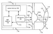
- FIG. 1Ais a block diagram of an embodiment of an illumination system comprising technology for detection of a change in the configuration of its elements.
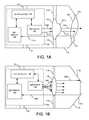
- FIG. 1Bis a block diagram of another embodiment of an illumination system comprising technology for detection of a change in the configuration of its elements.
- FIG. 2is a block diagram in a perspective view of an embodiment of a laser diode illumination system which can detect a change in the configuration of its elements.
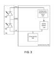
- FIG. 3is a block diagram of control circuitry in accordance with one embodiment for detecting a position configuration change of an element of the illumination system of FIG. 2 .
- FIG. 4is a block diagram in a perspective view of another embodiment of a laser diode illumination system comprising technology for detection of a change in the configuration of its elements.
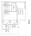
- FIG. 5is a block diagram of control circuitry in accordance with one embodiment for detecting a position configuration change of an element of the illumination system of FIG. 4 .
- FIG. 6is a flowchart of an embodiment of a method for detecting a change in a configuration position of one or more elements in an illumination system.
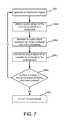
- FIG. 7is a flowchart of an implementation example of the method of FIG. 6 in an illumination system using reflected light as the indicator of a change in the position of one of the system's elements.
- FIG. 8is a graph illustrating some results of some data points for percentage changes in monitor photodiode current after removing an optical element vs. initial monitor photodiode currents before removal.
- An illumination systemtypically includes a light source and one or more optical elements.
- the light sourcemay be an off-the-shelf package, for example a standardized, commercially available package, including the light source and supporting circuitry fabricated using integrated circuit technology.
- a designer of the illumination systemconfigures one or more optical elements, for example mirrors and lenses, in positions to receive and process the light.
- Another example of an elementis a light blocking element.
- Other elements of the systemcan include structural elements like support structures on which the various elements are mounted, attached or supported in position. If the position of these elements is changed in the configuration, for example by significant movement, damage, or removal, the operation of the illumination or optical system is likely to be significantly compromised.
- the technologydetects a change in a configuration position of one or more elements in an illumination system by monitoring a portion of light of an illumination signal directed back to a light detector.
- a laserWhen a laser is used as the light source, the laser generates light or illumination which propagates mostly in one direction, referred to as forward, but also a smaller portion of light in an opposite direction to make up a reverse illumination signal.
- a monitor photodiodemonitors the reverse illumination signal as an indicator of the output power of the illumination signal for a laser.
- the forward illumination signalis the signal typically used by illumination systems in a wide variety of applications such as in cameras, lidars, spectrometers, etc. and is the signal referenced by the term illumination signal.
- An element of the illumination systemdirects a portion of the light of the signal back to the light detector.
- One way to direct a portion of the lightis to reflect the light.
- Some embodimentstake advantage of the inherent surface reflection of the light off of optical elements. Surface reflected light that is minimally scattered provides intensity measurements of surface reflected light that are easily detected over environmental factors such as noise.
- the light detectorgenerates an output signal based on the measurements of the light received back from the element. The output signal of the light detector is monitored to detect that a position of an element of the system has changed.
- an off-the-shelf integrated circuit light source packagesuch as that for a laser diode package which includes a monitor photodiode can be used to monitor changes outside the package.
- changescan be detected in the configuration of one or more optical elements of the illumination system which are outside the package.
- FIG. 1Ais a block diagram of an embodiment of an illumination system comprising technology for detection of a change in the configuration of its elements.
- An outer structure 118provides support for optical elements 124 and 122 and a package of a case or can 104 including integrated circuitry comprising a semiconductor light source 106 , control circuitry 126 and a light detector 108 .
- the optical elements 124 and 122are representative of lenses in this embodiment, but other optical or light processing elements (e.g. mirrors) may be used as per a particular optical design. Additionally, the illustrated lenses 124 and 122 may represent an optical subsystem of one or more optical elements.
- the light source 106generates an illumination signal, in this example represented as dispersive rays 109 f and 111 f .
- Semiconductor diodessuch as laser diodes and light-emitting diodes (LEDs) typically generate dispersive light beams unlike gas or crystal lasers which generate highly collimated beams.
- a collimating lens 124collimates the divergent light as illustrated.
- Optical element 122is a tilted optical element which reflects a portion of the collimated light.
- the tiltis not drawn to scale.
- the tilt anglemay be two to three (2-3) degrees.
- the reflected light 111 bpasses again through the one or more collimating lenses represented by lens 124 . In relation to the tilt angle, the reflected light 111 b travels to a location translated from, but near, the light source 106 where light detector 108 is located.
- Light detector 108is positioned to receive the reflected light 111 b .
- the light source 106is near, in this case behind, the light source 106 but extends beyond the area of the light source 106 and receives ray 111 b .
- the intensity measurement on the light detectorwill be higher due to the minimal scattering of the specularly reflected light than for light simply scattered back to the detector.
- FIG. 1Bis a block diagram of another embodiment of an illumination system comprising technology for detection of a change in the configuration of its elements.
- divergent ray 109 fis collimated by one or more lenses 124 and travels and intersects with a reflective area 115 a on a surface on an interior side of the outer structure 118 .
- a reflective area 115 a , 115 bmay be coated with a paint or coating which directs the light 109 b back to the light detector 108 through the one or more collimating lenses 124 .
- the structure 118may include a reflective area of coatings or mirrors in portions 115 a and 115 b .
- portions 115 a and 115 bmay form a trapezoid which is an incomplete corner of a cube due to the opening for the illumination signal between 115 a and 115 b .
- a corner reflectoris effectively formed as a reflective element.
- FIG. 2is a block diagram in a perspective view of an embodiment of a laser diode illumination system comprising technology for detection of a change in the configuration of its elements.
- the disclosure with respect to FIGS. 2 and 4is equally applicable to configurations with light-emitting diodes, which can share similar configurations to those depicted in FIGS. 2 and 4 .
- outer structural element 118 of the illumination systemsupports optical elements 124 and 122 .
- Lens 124is representative of one or more optical elements for collimating light beam 114 .
- Tilted optical element 122(not drawn to scale) has a tilt angle 120 measured from an axis 121 perpendicular to a direction of propagation of the illumination signal. As mentioned for FIG. 1A , in this example, the tilt angle may be between two to three degrees. Of course, other tilt angles may be used and different reflection arrangements according to design choice of the optical illumination system.
- Optical element 122can be implemented by one or more elements.
- the optical element 122represents one or more diffractive optical elements.
- a diffraction grating for the diffractive element 122provides a non-uniform or rough surface which directs light, for example surface reflects light back, toward the light detector.
- the laser diode lead LDis connected to a first lead of the control circuitry 126 which connects to a drive circuit 220 and a control system 218 .
- the control system 218maintains a constant current input via drive circuit 220 in this example.
- the laser diodemay be placed between the drive circuit 220 and common COM.
- the current level provided to the laser diodeis compared by the control system 218 with a set drive current level.
- the set drive current levelcan be represented by an analog voltage and compared with the actual current level, also represented as an analog voltage. Using the difference between the two voltages, representing an error, the input level of current to the laser diode can be adjusted to maintain a constant input drive signal to the laser.
- the monitor photodiode 108is not needed to monitor the output power of the laser in order to adjust the input power to achieve a selected output power.
- Photodiode lead PDconnects to a configuration measurement circuit 210 which in this example measures current.
- the type of photodiode usedmay output a current representative or based upon the light intensity received from the reverse illumination signal and the reflected light. In other examples, another characteristic of the output signal, for example voltage or phase or frequency, may be used as the measurement characteristic.
- the control system 218includes logic which may be in the form of firmware or software instructions which determines if the measured current is outside of a threshold stored in a memory such as a flash or a read only memory. Outside of a threshold may be above or below the threshold. For example, a measurement or a number of measurements may be above or below a certain amount of current indicating the configuration of at least one element has changed.
- a laser diodeproduces between about 190-200 milliwatts (mw) of power.
- the reverse illumination signalproduces an output signal of about 500 microamps uA.
- the reflected lightproduces an increase of about 2000 uA so an output signal of 2500 uA indicates the elements of the illumination system are in their intended positions within the configuration.
- the control systemdetects that there has been a change in the configuration position of the one or more optical elements outside the integrated light source package.
- Being outside the thresholdis an example of a criteria for modifying the operation of the illumination system.
- the criteriamay be a shut down criteria in which the control circuitry 126 turns off the light source, the laser diode in this example.
- the control system 218causes the drive circuit 220 to stop producing a drive signal for the laser diode 106 so the illumination system shuts down.
- the control circuitryprocesses the measurements of the configuration measurement circuit 210 as described above for FIG. 3 except the values will be reduced by the contribution of the reverse illumination signal.
- different types of reflectionmay be used to reflect the light back to the light detector.
- a mirror or other device with a surface having an angle of incidence of about zeromay reflect a portion of the illumination back to the light detector.
- retro-reflectionmay be used wherein light is reflected back toward its source as minimally scattered light or at least less scattered than diffusely reflected light.
- specular reflectionwhere the angle of incidence is equal to the angle of reflection is used.
- other elementsmay be used to direct a portion of the illumination outside a package to a photodiode within the package by other optical techniques than reflection. For example, a portion of the light may be split off by a splitter and routed through optical elements back to the light detector. In another example, light could be diffracted to a light detector placed in the package.
- FIG. 6is a flowchart of an embodiment of a method for detecting a change in a configuration position of one or more elements in an illumination system.
- a light source 106generates an illumination signal.
- An element of the illumination systemsuch as one or more tilted diffractive optical elements 122 as in FIG. 2 or the reflective areas 115 a and 115 b (for example being embodied as retro-reflective areas in some examples) of structural element 118 in FIG. 1B direct a portion of light of the illumination signal to a light detector 108 in step 304 .
- the control circuitry 126 in step 306monitors the directed light for detecting a change in a configuration position of one or more elements of the illumination system and determines in step 308 whether a change in the configuration position of one or more elements has occurred. Responsive to no change, the system continues operating by continuing to generate the illumination signal in step 302 and the monitoring of light directed back to the light detector. Responsive to a change in a configuration position of an element, the control circuitry 126 modifies operation of the illumination system in step 310 . In many cases for safety and proper operation concerns, the step 310 results in shutting down the illumination system.
- Step 306 of monitoring detected light for detecting a change in a configuration position of one or more elements of the illumination systemis implemented in step 306 a by the photodiode 108 , 107 generating an output signal representing the light-reflected back to the photodiode and in step 306 b monitoring the output signal as an indicator for a change in the reflected light.
- FIG. 8is a graph illustrating some results of some data points for percentage changes in monitor photodiode current after removing an optical element versus initial monitor photodiode currents before removal. The results were obtained for a system such as that in FIG. 2 wherein the diffractive optical element 122 was removed. For an initial monitor photodiode current of about 1.125 milliamps (ma) before removal, the percentage change was between about 25 and 30 percent. At an initial current of 1.6 ma, the percentage change after removal was between about 45 and 50 percent. For an initial current of 1.8 ma, the percentage change was about 55 percent after removal. As indicated, the changes in this range of currents indicated a fairly linear and direct relationship between initial monitor photodiode current and percentage change due to removal of the diffractive optical element 122 .
Landscapes
- Physics & Mathematics (AREA)
- Spectroscopy & Molecular Physics (AREA)
- General Physics & Mathematics (AREA)
- Length Measuring Devices By Optical Means (AREA)
- Optical Radar Systems And Details Thereof (AREA)
- Semiconductor Lasers (AREA)
Abstract
Description
Claims (20)
Priority Applications (1)
| Application Number | Priority Date | Filing Date | Title |
|---|---|---|---|
| US14/089,750US9291449B2 (en) | 2010-11-02 | 2013-11-25 | Detection of configuration changes among optical elements of illumination system |
Applications Claiming Priority (2)
| Application Number | Priority Date | Filing Date | Title |
|---|---|---|---|
| US12/938,254US8592739B2 (en) | 2010-11-02 | 2010-11-02 | Detection of configuration changes of an optical element in an illumination system |
| US14/089,750US9291449B2 (en) | 2010-11-02 | 2013-11-25 | Detection of configuration changes among optical elements of illumination system |
Related Parent Applications (1)
| Application Number | Title | Priority Date | Filing Date |
|---|---|---|---|
| US12/938,254ContinuationUS8592739B2 (en) | 2010-11-02 | 2010-11-02 | Detection of configuration changes of an optical element in an illumination system |
Publications (2)
| Publication Number | Publication Date |
|---|---|
| US20140160493A1 US20140160493A1 (en) | 2014-06-12 |
| US9291449B2true US9291449B2 (en) | 2016-03-22 |
Family
ID=45995606
Family Applications (2)
| Application Number | Title | Priority Date | Filing Date |
|---|---|---|---|
| US12/938,254Active2031-12-13US8592739B2 (en) | 2010-11-02 | 2010-11-02 | Detection of configuration changes of an optical element in an illumination system |
| US14/089,750Active2031-04-02US9291449B2 (en) | 2010-11-02 | 2013-11-25 | Detection of configuration changes among optical elements of illumination system |
Family Applications Before (1)
| Application Number | Title | Priority Date | Filing Date |
|---|---|---|---|
| US12/938,254Active2031-12-13US8592739B2 (en) | 2010-11-02 | 2010-11-02 | Detection of configuration changes of an optical element in an illumination system |
Country Status (2)
| Country | Link |
|---|---|
| US (2) | US8592739B2 (en) |
| CN (1) | CN103091071B (en) |
Families Citing this family (15)
| Publication number | Priority date | Publication date | Assignee | Title |
|---|---|---|---|---|
| US9366752B2 (en) | 2011-09-23 | 2016-06-14 | Apple Inc. | Proximity sensor with asymmetric optical element |
| US9263618B2 (en) | 2013-03-05 | 2016-02-16 | Apple Inc. | Proximity sensor module with light reflector |
| US9476968B2 (en)* | 2014-07-24 | 2016-10-25 | Rosemount Aerospace Inc. | System and method for monitoring optical subsystem performance in cloud LIDAR systems |
| US9854226B2 (en)* | 2014-12-22 | 2017-12-26 | Google Inc. | Illuminator for camera system having three dimensional time-of-flight capture with movable mirror element |
| JP6500474B2 (en)* | 2015-02-09 | 2019-04-17 | 株式会社島津製作所 | Optical analyzer |
| US9553423B2 (en) | 2015-02-27 | 2017-01-24 | Princeton Optronics Inc. | Miniature structured light illuminator |
| EP3095710B1 (en)* | 2015-05-20 | 2018-01-03 | Goodrich Lighting Systems GmbH | Dynamic exterior aircraft light unit and method of operating a dynamic exterior aircraft light unit |
| DE102015117265A1 (en)* | 2015-10-09 | 2017-04-13 | Endress+Hauser Conducta Gmbh+Co. Kg | Device for monitoring a light source of an optical sensor |
| DE102016104947A1 (en)* | 2016-03-17 | 2017-09-21 | Osram Opto Semiconductors Gmbh | Optoelectronic component and method for operating an optoelectronic component |
| EP3226555B1 (en) | 2016-03-28 | 2019-11-20 | Ricoh Company, Ltd. | Wavelength estimation device, light-source device, image display apparatus, wavelength estimation method, and light-source control method |
| US10031059B1 (en)* | 2017-01-20 | 2018-07-24 | Rosemount Aerospace Inc. | Controlled sampling volume of clouds for measuring cloud parameters |
| US11258234B2 (en)* | 2017-02-24 | 2022-02-22 | Princeton Optronics, Inc. | Eye safe VCSEL illuminator package |
| CN108333850A (en)* | 2018-02-27 | 2018-07-27 | 广东欧珀移动通信有限公司 | Laser projection module and its damage detection method, depth camera and electronic device |
| CN108490632B (en)* | 2018-03-12 | 2020-01-10 | Oppo广东移动通信有限公司 | Laser projection module, depth camera and electronic device |
| US11624836B2 (en) | 2019-09-24 | 2023-04-11 | Continental Autonomous Mobility US, LLC | Detection of damage to optical element of illumination system |
Citations (174)
| Publication number | Priority date | Publication date | Assignee | Title |
|---|---|---|---|---|
| US4627620A (en) | 1984-12-26 | 1986-12-09 | Yang John P | Electronic athlete trainer for improving skills in reflex, speed and accuracy |
| US4630910A (en) | 1984-02-16 | 1986-12-23 | Robotic Vision Systems, Inc. | Method of measuring in three-dimensions at high speed |
| US4645458A (en) | 1985-04-15 | 1987-02-24 | Harald Phillip | Athletic evaluation and training apparatus |
| US4695953A (en) | 1983-08-25 | 1987-09-22 | Blair Preston E | TV animation interactively controlled by the viewer |
| US4702475A (en) | 1985-08-16 | 1987-10-27 | Innovating Training Products, Inc. | Sports technique and reaction training system |
| US4711543A (en) | 1986-04-14 | 1987-12-08 | Blair Preston E | TV animation interactively controlled by the viewer |
| US4751642A (en) | 1986-08-29 | 1988-06-14 | Silva John M | Interactive sports simulation system with physiological sensing and psychological conditioning |
| US4796997A (en) | 1986-05-27 | 1989-01-10 | Synthetic Vision Systems, Inc. | Method and system for high-speed, 3-D imaging of an object at a vision station |
| US4809065A (en) | 1986-12-01 | 1989-02-28 | Kabushiki Kaisha Toshiba | Interactive system and related method for displaying data to produce a three-dimensional image of an object |
| US4817950A (en) | 1987-05-08 | 1989-04-04 | Goo Paul E | Video game control unit and attitude sensor |
| US4843568A (en) | 1986-04-11 | 1989-06-27 | Krueger Myron W | Real time perception of and response to the actions of an unencumbered participant/user |
| US4893183A (en) | 1988-08-11 | 1990-01-09 | Carnegie-Mellon University | Robotic vision system |
| US4901362A (en) | 1988-08-08 | 1990-02-13 | Raytheon Company | Method of recognizing patterns |
| US4925189A (en) | 1989-01-13 | 1990-05-15 | Braeunig Thomas F | Body-mounted video game exercise device |
| US5101444A (en) | 1990-05-18 | 1992-03-31 | Panacea, Inc. | Method and apparatus for high speed object location |
| US5148154A (en) | 1990-12-04 | 1992-09-15 | Sony Corporation Of America | Multi-dimensional user interface |
| US5184295A (en) | 1986-05-30 | 1993-02-02 | Mann Ralph V | System and method for teaching physical skills |
| US5190175A (en) | 1992-06-10 | 1993-03-02 | Continental White Cap, Inc. | Tamper evident closure |
| WO1993010708A1 (en) | 1991-12-03 | 1993-06-10 | French Sportech Corporation | Interactive video testing and training system |
| US5229754A (en) | 1990-02-13 | 1993-07-20 | Yazaki Corporation | Automotive reflection type display apparatus |
| US5229756A (en) | 1989-02-07 | 1993-07-20 | Yamaha Corporation | Image control apparatus |
| US5239464A (en) | 1988-08-04 | 1993-08-24 | Blair Preston E | Interactive video system providing repeated switching of multiple tracks of actions sequences |
| US5239463A (en) | 1988-08-04 | 1993-08-24 | Blair Preston E | Method and apparatus for player interaction with animated characters and objects |
| EP0583061A2 (en) | 1992-07-10 | 1994-02-16 | The Walt Disney Company | Method and apparatus for providing enhanced graphics in a virtual world |
| US5288078A (en) | 1988-10-14 | 1994-02-22 | David G. Capper | Control interface apparatus |
| US5295491A (en) | 1991-09-26 | 1994-03-22 | Sam Technology, Inc. | Non-invasive human neurocognitive performance capability testing method and system |
| US5306903A (en)* | 1991-07-08 | 1994-04-26 | Kabushiki Kaisha Toshiba | Objective lens position detecting system capable of adjusting amounts of radiation |
| US5320538A (en) | 1992-09-23 | 1994-06-14 | Hughes Training, Inc. | Interactive aircraft training system and method |
| US5347306A (en) | 1993-12-17 | 1994-09-13 | Mitsubishi Electric Research Laboratories, Inc. | Animated electronic meeting place |
| US5385519A (en) | 1994-04-19 | 1995-01-31 | Hsu; Chi-Hsueh | Running machine |
| US5405152A (en) | 1993-06-08 | 1995-04-11 | The Walt Disney Company | Method and apparatus for an interactive video game with physical feedback |
| US5417210A (en) | 1992-05-27 | 1995-05-23 | International Business Machines Corporation | System and method for augmentation of endoscopic surgery |
| US5423554A (en) | 1993-09-24 | 1995-06-13 | Metamedia Ventures, Inc. | Virtual reality game method and apparatus |
| US5454043A (en) | 1993-07-30 | 1995-09-26 | Mitsubishi Electric Research Laboratories, Inc. | Dynamic and static hand gesture recognition through low-level image analysis |
| US5469740A (en) | 1989-07-14 | 1995-11-28 | Impulse Technology, Inc. | Interactive video testing and training system |
| US5495576A (en) | 1993-01-11 | 1996-02-27 | Ritchey; Kurtis J. | Panoramic image based virtual reality/telepresence audio-visual system and method |
| US5516105A (en) | 1994-10-06 | 1996-05-14 | Exergame, Inc. | Acceleration activated joystick |
| US5524637A (en) | 1994-06-29 | 1996-06-11 | Erickson; Jon W. | Interactive system for measuring physiological exertion |
| US5534917A (en) | 1991-05-09 | 1996-07-09 | Very Vivid, Inc. | Video image based control system |
| US5563988A (en) | 1994-08-01 | 1996-10-08 | Massachusetts Institute Of Technology | Method and system for facilitating wireless, full-body, real-time user interaction with a digitally represented visual environment |
| US5569904A (en) | 1994-07-19 | 1996-10-29 | Eastman Kodak Company | Multispot autofocus system having a radiation emitter which emits radiation that is divided into a plurality of discrete beams |
| US5577981A (en) | 1994-01-19 | 1996-11-26 | Jarvik; Robert | Virtual reality exercise machine and computer controlled video system |
| US5580249A (en) | 1994-02-14 | 1996-12-03 | Sarcos Group | Apparatus for simulating mobility of a human |
| US5594469A (en) | 1995-02-21 | 1997-01-14 | Mitsubishi Electric Information Technology Center America Inc. | Hand gesture machine control system |
| US5597309A (en) | 1994-03-28 | 1997-01-28 | Riess; Thomas | Method and apparatus for treatment of gait problems associated with parkinson's disease |
| US5617312A (en) | 1993-11-19 | 1997-04-01 | Hitachi, Ltd. | Computer system that enters control information by means of video camera |
| US5616078A (en) | 1993-12-28 | 1997-04-01 | Konami Co., Ltd. | Motion-controlled video entertainment system |
| WO1997017598A1 (en) | 1995-11-06 | 1997-05-15 | Impulse Technology, Inc. | System for continuous monitoring of physical activity during unrestricted movement |
| US5638300A (en) | 1994-12-05 | 1997-06-10 | Johnson; Lee E. | Golf swing analysis system |
| US5641288A (en) | 1996-01-11 | 1997-06-24 | Zaenglein, Jr.; William G. | Shooting simulating process and training device using a virtual reality display screen |
| CN1159048A (en) | 1996-01-23 | 1997-09-10 | 三星电子株式会社 | Light output apparatus and optical pickup apparatus employing the same |
| US5682196A (en) | 1995-06-22 | 1997-10-28 | Actv, Inc. | Three-dimensional (3D) video presentation system providing interactive 3D presentation with personalized audio responses for multiple viewers |
| US5682229A (en) | 1995-04-14 | 1997-10-28 | Schwartz Electro-Optics, Inc. | Laser range camera |
| US5690582A (en) | 1993-02-02 | 1997-11-25 | Tectrix Fitness Equipment, Inc. | Interactive exercise apparatus |
| US5703367A (en) | 1994-12-09 | 1997-12-30 | Matsushita Electric Industrial Co., Ltd. | Human occupancy detection method and system for implementing the same |
| CN1169009A (en) | 1996-04-18 | 1997-12-31 | 三星电子株式会社 | Laser diode elements with light yield mornitoring function |
| US5704837A (en) | 1993-03-26 | 1998-01-06 | Namco Ltd. | Video game steering system causing translation, rotation and curvilinear motion on the object |
| US5715834A (en) | 1992-11-20 | 1998-02-10 | Scuola Superiore Di Studi Universitari & Di Perfezionamento S. Anna | Device for monitoring the configuration of a distal physiological unit for use, in particular, as an advanced interface for machine and computers |
| US5875108A (en) | 1991-12-23 | 1999-02-23 | Hoffberg; Steven M. | Ergonomic man-machine interface incorporating adaptive pattern recognition based control system |
| US5877803A (en) | 1997-04-07 | 1999-03-02 | Tritech Mircoelectronics International, Ltd. | 3-D image detector |
| US5913727A (en) | 1995-06-02 | 1999-06-22 | Ahdoot; Ned | Interactive movement and contact simulation game |
| US5933125A (en) | 1995-11-27 | 1999-08-03 | Cae Electronics, Ltd. | Method and apparatus for reducing instability in the display of a virtual environment |
| US5980256A (en) | 1993-10-29 | 1999-11-09 | Carmein; David E. E. | Virtual reality system with enhanced sensory apparatus |
| US5989157A (en) | 1996-08-06 | 1999-11-23 | Walton; Charles A. | Exercising system with electronic inertial game playing |
| US5995649A (en) | 1996-09-20 | 1999-11-30 | Nec Corporation | Dual-input image processor for recognizing, isolating, and displaying specific objects from the input images |
| US6005548A (en) | 1996-08-14 | 1999-12-21 | Latypov; Nurakhmed Nurislamovich | Method for tracking and displaying user's spatial position and orientation, a method for representing virtual reality for a user, and systems of embodiment of such methods |
| US6009210A (en) | 1997-03-05 | 1999-12-28 | Digital Equipment Corporation | Hands-free interface to a virtual reality environment using head tracking |
| US6054991A (en) | 1991-12-02 | 2000-04-25 | Texas Instruments Incorporated | Method of modeling player position and movement in a virtual reality system |
| US6066075A (en) | 1995-07-26 | 2000-05-23 | Poulton; Craig K. | Direct feedback controller for user interaction |
| US6072494A (en) | 1997-10-15 | 2000-06-06 | Electric Planet, Inc. | Method and apparatus for real-time gesture recognition |
| US6073489A (en) | 1995-11-06 | 2000-06-13 | French; Barry J. | Testing and training system for assessing the ability of a player to complete a task |
| US6077201A (en) | 1998-06-12 | 2000-06-20 | Cheng; Chau-Yang | Exercise bicycle |
| US6101289A (en) | 1997-10-15 | 2000-08-08 | Electric Planet, Inc. | Method and apparatus for unencumbered capture of an object |
| US6100896A (en) | 1997-03-24 | 2000-08-08 | Mitsubishi Electric Information Technology Center America, Inc. | System for designing graphical multi-participant environments |
| US6128003A (en) | 1996-12-20 | 2000-10-03 | Hitachi, Ltd. | Hand gesture recognition system and method |
| US6130677A (en) | 1997-10-15 | 2000-10-10 | Electric Planet, Inc. | Interactive computer vision system |
| US6141463A (en) | 1997-10-10 | 2000-10-31 | Electric Planet Interactive | Method and system for estimating jointed-figure configurations |
| US6147678A (en) | 1998-12-09 | 2000-11-14 | Lucent Technologies Inc. | Video hand image-three-dimensional computer interface with multiple degrees of freedom |
| US6152856A (en) | 1996-05-08 | 2000-11-28 | Real Vision Corporation | Real time simulation using position sensing |
| US6159100A (en) | 1998-04-23 | 2000-12-12 | Smith; Michael D. | Virtual reality game |
| US6173066B1 (en) | 1996-05-21 | 2001-01-09 | Cybernet Systems Corporation | Pose determination and tracking by matching 3D objects to a 2D sensor |
| US6181343B1 (en) | 1997-12-23 | 2001-01-30 | Philips Electronics North America Corp. | System and method for permitting three-dimensional navigation through a virtual reality environment using camera-based gesture inputs |
| US6188777B1 (en) | 1997-08-01 | 2001-02-13 | Interval Research Corporation | Method and apparatus for personnel detection and tracking |
| US6215890B1 (en) | 1997-09-26 | 2001-04-10 | Matsushita Electric Industrial Co., Ltd. | Hand gesture recognizing device |
| US6215898B1 (en) | 1997-04-15 | 2001-04-10 | Interval Research Corporation | Data processing system and method |
| US6226396B1 (en) | 1997-07-31 | 2001-05-01 | Nec Corporation | Object extraction method and system |
| US6229913B1 (en) | 1995-06-07 | 2001-05-08 | The Trustees Of Columbia University In The City Of New York | Apparatus and methods for determining the three-dimensional shape of an object using active illumination and relative blurring in two-images due to defocus |
| US6256400B1 (en) | 1998-09-28 | 2001-07-03 | Matsushita Electric Industrial Co., Ltd. | Method and device for segmenting hand gestures |
| US6283860B1 (en) | 1995-11-07 | 2001-09-04 | Philips Electronics North America Corp. | Method, system, and program for gesture based option selection |
| US6289112B1 (en) | 1997-08-22 | 2001-09-11 | International Business Machines Corporation | System and method for determining block direction in fingerprint images |
| US6299308B1 (en) | 1999-04-02 | 2001-10-09 | Cybernet Systems Corporation | Low-cost non-imaging eye tracker system for computer control |
| US6308565B1 (en) | 1995-11-06 | 2001-10-30 | Impulse Technology Ltd. | System and method for tracking and assessing movement skills in multidimensional space |
| US6316934B1 (en) | 1998-09-17 | 2001-11-13 | Netmor Ltd. | System for three dimensional positioning and tracking |
| US6363160B1 (en) | 1999-01-22 | 2002-03-26 | Intel Corporation | Interface using pattern recognition and tracking |
| US6384819B1 (en) | 1997-10-15 | 2002-05-07 | Electric Planet, Inc. | System and method for generating an animatable character |
| US6411744B1 (en) | 1997-10-15 | 2002-06-25 | Electric Planet, Inc. | Method and apparatus for performing a clean background subtraction |
| US6430997B1 (en) | 1995-11-06 | 2002-08-13 | Trazer Technologies, Inc. | System and method for tracking and assessing movement skills in multidimensional space |
| US6476834B1 (en) | 1999-05-28 | 2002-11-05 | International Business Machines Corporation | Dynamic creation of selectable items on surfaces |
| US6496598B1 (en) | 1997-09-02 | 2002-12-17 | Dynamic Digital Depth Research Pty. Ltd. | Image processing method and apparatus |
| US6503195B1 (en) | 1999-05-24 | 2003-01-07 | University Of North Carolina At Chapel Hill | Methods and systems for real-time structured light depth extraction and endoscope using real-time structured light depth extraction |
| CN1395677A (en) | 2000-01-19 | 2003-02-05 | 海德堡显微技术仪器股份有限公司 | Method and arrangement for optically detecting position of moveable mirror |
| US20030057355A1 (en) | 2001-09-24 | 2003-03-27 | Cheng-Bin Wang | Auto feedback and photo attenuation structure of vertical cavity surface emitting laser |
| US6539931B2 (en) | 2001-04-16 | 2003-04-01 | Koninklijke Philips Electronics N.V. | Ball throwing assistant |
| US6570555B1 (en) | 1998-12-30 | 2003-05-27 | Fuji Xerox Co., Ltd. | Method and apparatus for embodied conversational characters with multimodal input/output in an interface device |
| US6633294B1 (en) | 2000-03-09 | 2003-10-14 | Seth Rosenthal | Method and apparatus for using captured high density motion for animation |
| US6640202B1 (en) | 2000-05-25 | 2003-10-28 | International Business Machines Corporation | Elastic sensor mesh system for 3-dimensional measurement, mapping and kinematics applications |
| US6661918B1 (en) | 1998-12-04 | 2003-12-09 | Interval Research Corporation | Background estimation and segmentation based on range and color |
| US6681031B2 (en) | 1998-08-10 | 2004-01-20 | Cybernet Systems Corporation | Gesture-controlled interfaces for self-service machines and other applications |
| US6714665B1 (en) | 1994-09-02 | 2004-03-30 | Sarnoff Corporation | Fully automated iris recognition system utilizing wide and narrow fields of view |
| US6731799B1 (en) | 2000-06-01 | 2004-05-04 | University Of Washington | Object segmentation with background extraction and moving boundary techniques |
| US6738066B1 (en) | 1999-07-30 | 2004-05-18 | Electric Plant, Inc. | System, method and article of manufacture for detecting collisions between video images generated by a camera and an object depicted on a display |
| US6788809B1 (en) | 2000-06-30 | 2004-09-07 | Intel Corporation | System and method for gesture recognition in three dimensions using stereo imaging and color vision |
| US6801637B2 (en) | 1999-08-10 | 2004-10-05 | Cybernet Systems Corporation | Optical body tracker |
| US6810135B1 (en) | 2000-06-29 | 2004-10-26 | Trw Inc. | Optimized human presence detection through elimination of background interference |
| US20040228577A1 (en) | 2000-10-30 | 2004-11-18 | Bardia Pezeshki | Laser and fiber coupling control |
| US6873723B1 (en) | 1999-06-30 | 2005-03-29 | Intel Corporation | Segmenting three-dimensional video images using stereo |
| US6937742B2 (en) | 2001-09-28 | 2005-08-30 | Bellsouth Intellectual Property Corporation | Gesture activated home appliance |
| US6950534B2 (en) | 1998-08-10 | 2005-09-27 | Cybernet Systems Corporation | Gesture-controlled interfaces for self-service machines and other applications |
| US7003134B1 (en) | 1999-03-08 | 2006-02-21 | Vulcan Patents Llc | Three dimensional object pose estimation which employs dense depth information |
| CN1738117A (en) | 2004-08-20 | 2006-02-22 | 安捷伦科技公司 | self-monitoring light emitting device |
| US7036094B1 (en) | 1998-08-10 | 2006-04-25 | Cybernet Systems Corporation | Behavior recognition system |
| US7039676B1 (en) | 2000-10-31 | 2006-05-02 | International Business Machines Corporation | Using video image analysis to automatically transmit gestures over a network in a chat or instant messaging session |
| US7042440B2 (en) | 1997-08-22 | 2006-05-09 | Pryor Timothy R | Man machine interfaces and applications |
| US7050606B2 (en) | 1999-08-10 | 2006-05-23 | Cybernet Systems Corporation | Tracking and gesture recognition system particularly suited to vehicular control applications |
| US7058204B2 (en) | 2000-10-03 | 2006-06-06 | Gesturetek, Inc. | Multiple camera control system |
| US7060957B2 (en) | 2000-04-28 | 2006-06-13 | Csem Centre Suisse D'electronique Et Microtechinique Sa | Device and method for spatially resolved photodetection and demodulation of modulated electromagnetic waves |
| CN1800836A (en) | 2004-12-24 | 2006-07-12 | 奥林巴斯株式会社 | Image testing device |
| US7113918B1 (en) | 1999-08-01 | 2006-09-26 | Electric Planet, Inc. | Method for video enabled electronic commerce |
| US7121946B2 (en) | 1998-08-10 | 2006-10-17 | Cybernet Systems Corporation | Real-time head tracking system for computer games and other applications |
| US7170492B2 (en) | 2002-05-28 | 2007-01-30 | Reactrix Systems, Inc. | Interactive video display system |
| US7202898B1 (en) | 1998-12-16 | 2007-04-10 | 3Dv Systems Ltd. | Self gating photosurface |
| US7210859B2 (en) | 2002-02-14 | 2007-05-01 | Finisar Corporation | Optoelectronic components with multi-layer feedthrough structure |
| US7222078B2 (en) | 1992-08-06 | 2007-05-22 | Ferrara Ethereal Llc | Methods and systems for gathering information from units of a commodity across a network |
| US7227526B2 (en) | 2000-07-24 | 2007-06-05 | Gesturetek, Inc. | Video-based image control system |
| US7259747B2 (en) | 2001-06-05 | 2007-08-21 | Reactrix Systems, Inc. | Interactive video display system |
| US7308112B2 (en) | 2004-05-14 | 2007-12-11 | Honda Motor Co., Ltd. | Sign based human-machine interaction |
| US7317836B2 (en) | 2005-03-17 | 2008-01-08 | Honda Motor Co., Ltd. | Pose estimation based on critical point analysis |
| US20080026838A1 (en) | 2005-08-22 | 2008-01-31 | Dunstan James E | Multi-player non-role-playing virtual world games: method for two-way interaction between participants and multi-player virtual world games |
| US7348963B2 (en) | 2002-05-28 | 2008-03-25 | Reactrix Systems, Inc. | Interactive video display system |
| US7367887B2 (en) | 2000-02-18 | 2008-05-06 | Namco Bandai Games Inc. | Game apparatus, storage medium, and computer program that adjust level of game difficulty |
| US7379563B2 (en) | 2004-04-15 | 2008-05-27 | Gesturetek, Inc. | Tracking bimanual movements |
| US7379566B2 (en) | 2005-01-07 | 2008-05-27 | Gesturetek, Inc. | Optical flow based tilt sensor |
| US7388486B2 (en) | 2006-01-05 | 2008-06-17 | Honeywell International Inc. | Method and system to detect tampering using light detector |
| US7389591B2 (en) | 2005-05-17 | 2008-06-24 | Gesturetek, Inc. | Orientation-sensitive signal output |
| US7412077B2 (en) | 2006-12-29 | 2008-08-12 | Motorola, Inc. | Apparatus and methods for head pose estimation and head gesture detection |
| US7430312B2 (en) | 2005-01-07 | 2008-09-30 | Gesturetek, Inc. | Creating 3D images of objects by illuminating with infrared patterns |
| US7436496B2 (en) | 2003-02-03 | 2008-10-14 | National University Corporation Shizuoka University | Distance image sensor |
| US7443587B2 (en) | 1999-04-30 | 2008-10-28 | Metrologic Instruments, Inc. | DOE-based systems and devices for producing laser beams having modified beam characteristics |
| US7450736B2 (en) | 2005-10-28 | 2008-11-11 | Honda Motor Co., Ltd. | Monocular tracking of 3D human motion with a coordinated mixture of factor analyzers |
| US7452275B2 (en) | 2001-06-29 | 2008-11-18 | Konami Digital Entertainment Co., Ltd. | Game device, game controlling method and program |
| US7489812B2 (en) | 2002-06-07 | 2009-02-10 | Dynamic Digital Depth Research Pty Ltd. | Conversion and encoding techniques |
| US20090039235A1 (en) | 2005-11-16 | 2009-02-12 | Macfarlane Duncan L | Method for determining location and movement of a moving object |
| US7518507B2 (en) | 2005-11-14 | 2009-04-14 | Honeywell International Inc. | Method and system to detect tampering of a closed chassis using a passive fiber optic sensor |
| US7536032B2 (en) | 2003-10-24 | 2009-05-19 | Reactrix Systems, Inc. | Method and system for processing captured image information in an interactive video display system |
| US7560701B2 (en) | 2005-08-12 | 2009-07-14 | Mesa Imaging Ag | Highly sensitive, fast pixel for use in an image sensor |
| US7574020B2 (en) | 2005-01-07 | 2009-08-11 | Gesturetek, Inc. | Detecting and tracking objects in images |
| US7576727B2 (en) | 2002-12-13 | 2009-08-18 | Matthew Bell | Interactive directed light/sound system |
| US7590262B2 (en) | 2003-05-29 | 2009-09-15 | Honda Motor Co., Ltd. | Visual tracking using depth data |
| US7593552B2 (en) | 2003-03-31 | 2009-09-22 | Honda Motor Co., Ltd. | Gesture recognition apparatus, gesture recognition method, and gesture recognition program |
| US7598942B2 (en) | 2005-02-08 | 2009-10-06 | Oblong Industries, Inc. | System and method for gesture based control system |
| US7607509B2 (en) | 2002-04-19 | 2009-10-27 | Iee International Electronics & Engineering S.A. | Safety device for a vehicle |
| US7620202B2 (en) | 2003-06-12 | 2009-11-17 | Honda Motor Co., Ltd. | Target orientation estimation using depth sensing |
| US20100006741A1 (en) | 2008-07-10 | 2010-01-14 | Funai Electric Co., Ltd. | Device and method for displaying image |
| US7684592B2 (en) | 1998-08-10 | 2010-03-23 | Cybernet Systems Corporation | Realtime object tracking system |
| US7683954B2 (en) | 2006-09-29 | 2010-03-23 | Brainvision Inc. | Solid-state image sensor |
| US7701439B2 (en) | 2006-07-13 | 2010-04-20 | Northrop Grumman Corporation | Gesture recognition simulation system and method |
| US7702130B2 (en) | 2004-12-20 | 2010-04-20 | Electronics And Telecommunications Research Institute | User interface apparatus using hand gesture recognition and method thereof |
| US7704135B2 (en) | 2004-08-23 | 2010-04-27 | Harrison Jr Shelton E | Integrated game system, method, and device |
| US7710391B2 (en) | 2002-05-28 | 2010-05-04 | Matthew Bell | Processing an image utilizing a spatially varying pattern |
| US7729530B2 (en) | 2007-03-03 | 2010-06-01 | Sergey Antonov | Method and apparatus for 3-D data input to a personal computer with a multimedia oriented operating system |
| CN101254344B (en) | 2008-04-18 | 2010-06-16 | 李刚 | Game device of field orientation corresponding with display screen dot array in proportion and method |
| US7852262B2 (en) | 2007-08-16 | 2010-12-14 | Cybernet Systems Corporation | Wireless mobile indoor/outdoor tracking system |
| US8035612B2 (en) | 2002-05-28 | 2011-10-11 | Intellectual Ventures Holding 67 Llc | Self-contained interactive video display system |
| US8072470B2 (en) | 2003-05-29 | 2011-12-06 | Sony Computer Entertainment Inc. | System and method for providing a real-time three-dimensional interactive environment |
- 2010
- 2010-11-02USUS12/938,254patent/US8592739B2/enactiveActive
- 2011
- 2011-11-01CNCN201110352669.3Apatent/CN103091071B/enactiveActive
- 2013
- 2013-11-25USUS14/089,750patent/US9291449B2/enactiveActive
Patent Citations (196)
| Publication number | Priority date | Publication date | Assignee | Title |
|---|---|---|---|---|
| US4695953A (en) | 1983-08-25 | 1987-09-22 | Blair Preston E | TV animation interactively controlled by the viewer |
| US4630910A (en) | 1984-02-16 | 1986-12-23 | Robotic Vision Systems, Inc. | Method of measuring in three-dimensions at high speed |
| US4627620A (en) | 1984-12-26 | 1986-12-09 | Yang John P | Electronic athlete trainer for improving skills in reflex, speed and accuracy |
| US4645458A (en) | 1985-04-15 | 1987-02-24 | Harald Phillip | Athletic evaluation and training apparatus |
| US4702475A (en) | 1985-08-16 | 1987-10-27 | Innovating Training Products, Inc. | Sports technique and reaction training system |
| US4843568A (en) | 1986-04-11 | 1989-06-27 | Krueger Myron W | Real time perception of and response to the actions of an unencumbered participant/user |
| US4711543A (en) | 1986-04-14 | 1987-12-08 | Blair Preston E | TV animation interactively controlled by the viewer |
| US4796997A (en) | 1986-05-27 | 1989-01-10 | Synthetic Vision Systems, Inc. | Method and system for high-speed, 3-D imaging of an object at a vision station |
| US5184295A (en) | 1986-05-30 | 1993-02-02 | Mann Ralph V | System and method for teaching physical skills |
| US4751642A (en) | 1986-08-29 | 1988-06-14 | Silva John M | Interactive sports simulation system with physiological sensing and psychological conditioning |
| US4809065A (en) | 1986-12-01 | 1989-02-28 | Kabushiki Kaisha Toshiba | Interactive system and related method for displaying data to produce a three-dimensional image of an object |
| US4817950A (en) | 1987-05-08 | 1989-04-04 | Goo Paul E | Video game control unit and attitude sensor |
| US5239463A (en) | 1988-08-04 | 1993-08-24 | Blair Preston E | Method and apparatus for player interaction with animated characters and objects |
| US5239464A (en) | 1988-08-04 | 1993-08-24 | Blair Preston E | Interactive video system providing repeated switching of multiple tracks of actions sequences |
| US4901362A (en) | 1988-08-08 | 1990-02-13 | Raytheon Company | Method of recognizing patterns |
| US4893183A (en) | 1988-08-11 | 1990-01-09 | Carnegie-Mellon University | Robotic vision system |
| US5288078A (en) | 1988-10-14 | 1994-02-22 | David G. Capper | Control interface apparatus |
| US4925189A (en) | 1989-01-13 | 1990-05-15 | Braeunig Thomas F | Body-mounted video game exercise device |
| US5229756A (en) | 1989-02-07 | 1993-07-20 | Yamaha Corporation | Image control apparatus |
| US5469740A (en) | 1989-07-14 | 1995-11-28 | Impulse Technology, Inc. | Interactive video testing and training system |
| US5229754A (en) | 1990-02-13 | 1993-07-20 | Yazaki Corporation | Automotive reflection type display apparatus |
| US5101444A (en) | 1990-05-18 | 1992-03-31 | Panacea, Inc. | Method and apparatus for high speed object location |
| US5148154A (en) | 1990-12-04 | 1992-09-15 | Sony Corporation Of America | Multi-dimensional user interface |
| US5534917A (en) | 1991-05-09 | 1996-07-09 | Very Vivid, Inc. | Video image based control system |
| US5306903A (en)* | 1991-07-08 | 1994-04-26 | Kabushiki Kaisha Toshiba | Objective lens position detecting system capable of adjusting amounts of radiation |
| US5295491A (en) | 1991-09-26 | 1994-03-22 | Sam Technology, Inc. | Non-invasive human neurocognitive performance capability testing method and system |
| US6054991A (en) | 1991-12-02 | 2000-04-25 | Texas Instruments Incorporated | Method of modeling player position and movement in a virtual reality system |
| WO1993010708A1 (en) | 1991-12-03 | 1993-06-10 | French Sportech Corporation | Interactive video testing and training system |
| US5875108A (en) | 1991-12-23 | 1999-02-23 | Hoffberg; Steven M. | Ergonomic man-machine interface incorporating adaptive pattern recognition based control system |
| US5417210A (en) | 1992-05-27 | 1995-05-23 | International Business Machines Corporation | System and method for augmentation of endoscopic surgery |
| US5190175A (en) | 1992-06-10 | 1993-03-02 | Continental White Cap, Inc. | Tamper evident closure |
| EP0583061A2 (en) | 1992-07-10 | 1994-02-16 | The Walt Disney Company | Method and apparatus for providing enhanced graphics in a virtual world |
| US7222078B2 (en) | 1992-08-06 | 2007-05-22 | Ferrara Ethereal Llc | Methods and systems for gathering information from units of a commodity across a network |
| US5320538A (en) | 1992-09-23 | 1994-06-14 | Hughes Training, Inc. | Interactive aircraft training system and method |
| US5715834A (en) | 1992-11-20 | 1998-02-10 | Scuola Superiore Di Studi Universitari & Di Perfezionamento S. Anna | Device for monitoring the configuration of a distal physiological unit for use, in particular, as an advanced interface for machine and computers |
| US5495576A (en) | 1993-01-11 | 1996-02-27 | Ritchey; Kurtis J. | Panoramic image based virtual reality/telepresence audio-visual system and method |
| US5690582A (en) | 1993-02-02 | 1997-11-25 | Tectrix Fitness Equipment, Inc. | Interactive exercise apparatus |
| US5704837A (en) | 1993-03-26 | 1998-01-06 | Namco Ltd. | Video game steering system causing translation, rotation and curvilinear motion on the object |
| US5405152A (en) | 1993-06-08 | 1995-04-11 | The Walt Disney Company | Method and apparatus for an interactive video game with physical feedback |
| US5454043A (en) | 1993-07-30 | 1995-09-26 | Mitsubishi Electric Research Laboratories, Inc. | Dynamic and static hand gesture recognition through low-level image analysis |
| US5423554A (en) | 1993-09-24 | 1995-06-13 | Metamedia Ventures, Inc. | Virtual reality game method and apparatus |
| US5980256A (en) | 1993-10-29 | 1999-11-09 | Carmein; David E. E. | Virtual reality system with enhanced sensory apparatus |
| US5617312A (en) | 1993-11-19 | 1997-04-01 | Hitachi, Ltd. | Computer system that enters control information by means of video camera |
| US5347306A (en) | 1993-12-17 | 1994-09-13 | Mitsubishi Electric Research Laboratories, Inc. | Animated electronic meeting place |
| US5616078A (en) | 1993-12-28 | 1997-04-01 | Konami Co., Ltd. | Motion-controlled video entertainment system |
| US5577981A (en) | 1994-01-19 | 1996-11-26 | Jarvik; Robert | Virtual reality exercise machine and computer controlled video system |
| US5580249A (en) | 1994-02-14 | 1996-12-03 | Sarcos Group | Apparatus for simulating mobility of a human |
| US5597309A (en) | 1994-03-28 | 1997-01-28 | Riess; Thomas | Method and apparatus for treatment of gait problems associated with parkinson's disease |
| US5385519A (en) | 1994-04-19 | 1995-01-31 | Hsu; Chi-Hsueh | Running machine |
| US5524637A (en) | 1994-06-29 | 1996-06-11 | Erickson; Jon W. | Interactive system for measuring physiological exertion |
| US5569904A (en) | 1994-07-19 | 1996-10-29 | Eastman Kodak Company | Multispot autofocus system having a radiation emitter which emits radiation that is divided into a plurality of discrete beams |
| US5563988A (en) | 1994-08-01 | 1996-10-08 | Massachusetts Institute Of Technology | Method and system for facilitating wireless, full-body, real-time user interaction with a digitally represented visual environment |
| US6714665B1 (en) | 1994-09-02 | 2004-03-30 | Sarnoff Corporation | Fully automated iris recognition system utilizing wide and narrow fields of view |
| US5516105A (en) | 1994-10-06 | 1996-05-14 | Exergame, Inc. | Acceleration activated joystick |
| US5638300A (en) | 1994-12-05 | 1997-06-10 | Johnson; Lee E. | Golf swing analysis system |
| US5703367A (en) | 1994-12-09 | 1997-12-30 | Matsushita Electric Industrial Co., Ltd. | Human occupancy detection method and system for implementing the same |
| US5594469A (en) | 1995-02-21 | 1997-01-14 | Mitsubishi Electric Information Technology Center America Inc. | Hand gesture machine control system |
| US5682229A (en) | 1995-04-14 | 1997-10-28 | Schwartz Electro-Optics, Inc. | Laser range camera |
| US5913727A (en) | 1995-06-02 | 1999-06-22 | Ahdoot; Ned | Interactive movement and contact simulation game |
| US6229913B1 (en) | 1995-06-07 | 2001-05-08 | The Trustees Of Columbia University In The City Of New York | Apparatus and methods for determining the three-dimensional shape of an object using active illumination and relative blurring in two-images due to defocus |
| US5682196A (en) | 1995-06-22 | 1997-10-28 | Actv, Inc. | Three-dimensional (3D) video presentation system providing interactive 3D presentation with personalized audio responses for multiple viewers |
| US6066075A (en) | 1995-07-26 | 2000-05-23 | Poulton; Craig K. | Direct feedback controller for user interaction |
| US7359121B2 (en) | 1995-11-06 | 2008-04-15 | Impulse Technology Ltd. | System and method for tracking and assessing movement skills in multidimensional space |
| US6308565B1 (en) | 1995-11-06 | 2001-10-30 | Impulse Technology Ltd. | System and method for tracking and assessing movement skills in multidimensional space |
| US7038855B2 (en) | 1995-11-06 | 2006-05-02 | Impulse Technology Ltd. | System and method for tracking and assessing movement skills in multidimensional space |
| US6430997B1 (en) | 1995-11-06 | 2002-08-13 | Trazer Technologies, Inc. | System and method for tracking and assessing movement skills in multidimensional space |
| WO1997017598A1 (en) | 1995-11-06 | 1997-05-15 | Impulse Technology, Inc. | System for continuous monitoring of physical activity during unrestricted movement |
| US6098458A (en) | 1995-11-06 | 2000-08-08 | Impulse Technology, Ltd. | Testing and training system for assessing movement and agility skills without a confining field |
| US6765726B2 (en) | 1995-11-06 | 2004-07-20 | Impluse Technology Ltd. | System and method for tracking and assessing movement skills in multidimensional space |
| US6876496B2 (en) | 1995-11-06 | 2005-04-05 | Impulse Technology Ltd. | System and method for tracking and assessing movement skills in multidimensional space |
| US6073489A (en) | 1995-11-06 | 2000-06-13 | French; Barry J. | Testing and training system for assessing the ability of a player to complete a task |
| US6283860B1 (en) | 1995-11-07 | 2001-09-04 | Philips Electronics North America Corp. | Method, system, and program for gesture based option selection |
| US5933125A (en) | 1995-11-27 | 1999-08-03 | Cae Electronics, Ltd. | Method and apparatus for reducing instability in the display of a virtual environment |
| US5641288A (en) | 1996-01-11 | 1997-06-24 | Zaenglein, Jr.; William G. | Shooting simulating process and training device using a virtual reality display screen |
| CN1159048A (en) | 1996-01-23 | 1997-09-10 | 三星电子株式会社 | Light output apparatus and optical pickup apparatus employing the same |
| CN1169009A (en) | 1996-04-18 | 1997-12-31 | 三星电子株式会社 | Laser diode elements with light yield mornitoring function |
| US6152856A (en) | 1996-05-08 | 2000-11-28 | Real Vision Corporation | Real time simulation using position sensing |
| US6173066B1 (en) | 1996-05-21 | 2001-01-09 | Cybernet Systems Corporation | Pose determination and tracking by matching 3D objects to a 2D sensor |
| US5989157A (en) | 1996-08-06 | 1999-11-23 | Walton; Charles A. | Exercising system with electronic inertial game playing |
| US6005548A (en) | 1996-08-14 | 1999-12-21 | Latypov; Nurakhmed Nurislamovich | Method for tracking and displaying user's spatial position and orientation, a method for representing virtual reality for a user, and systems of embodiment of such methods |
| US5995649A (en) | 1996-09-20 | 1999-11-30 | Nec Corporation | Dual-input image processor for recognizing, isolating, and displaying specific objects from the input images |
| US6128003A (en) | 1996-12-20 | 2000-10-03 | Hitachi, Ltd. | Hand gesture recognition system and method |
| US6009210A (en) | 1997-03-05 | 1999-12-28 | Digital Equipment Corporation | Hands-free interface to a virtual reality environment using head tracking |
| US6100896A (en) | 1997-03-24 | 2000-08-08 | Mitsubishi Electric Information Technology Center America, Inc. | System for designing graphical multi-participant environments |
| US5877803A (en) | 1997-04-07 | 1999-03-02 | Tritech Mircoelectronics International, Ltd. | 3-D image detector |
| US6215898B1 (en) | 1997-04-15 | 2001-04-10 | Interval Research Corporation | Data processing system and method |
| US6226396B1 (en) | 1997-07-31 | 2001-05-01 | Nec Corporation | Object extraction method and system |
| US6188777B1 (en) | 1997-08-01 | 2001-02-13 | Interval Research Corporation | Method and apparatus for personnel detection and tracking |
| US6289112B1 (en) | 1997-08-22 | 2001-09-11 | International Business Machines Corporation | System and method for determining block direction in fingerprint images |
| US7042440B2 (en) | 1997-08-22 | 2006-05-09 | Pryor Timothy R | Man machine interfaces and applications |
| US6496598B1 (en) | 1997-09-02 | 2002-12-17 | Dynamic Digital Depth Research Pty. Ltd. | Image processing method and apparatus |
| US6215890B1 (en) | 1997-09-26 | 2001-04-10 | Matsushita Electric Industrial Co., Ltd. | Hand gesture recognizing device |
| US6141463A (en) | 1997-10-10 | 2000-10-31 | Electric Planet Interactive | Method and system for estimating jointed-figure configurations |
| US6411744B1 (en) | 1997-10-15 | 2002-06-25 | Electric Planet, Inc. | Method and apparatus for performing a clean background subtraction |
| USRE42256E1 (en) | 1997-10-15 | 2011-03-29 | Elet Systems L.L.C. | Method and apparatus for performing a clean background subtraction |
| US6101289A (en) | 1997-10-15 | 2000-08-08 | Electric Planet, Inc. | Method and apparatus for unencumbered capture of an object |
| US6384819B1 (en) | 1997-10-15 | 2002-05-07 | Electric Planet, Inc. | System and method for generating an animatable character |
| US7746345B2 (en) | 1997-10-15 | 2010-06-29 | Hunter Kevin L | System and method for generating an animatable character |
| US6130677A (en) | 1997-10-15 | 2000-10-10 | Electric Planet, Inc. | Interactive computer vision system |
| US6256033B1 (en) | 1997-10-15 | 2001-07-03 | Electric Planet | Method and apparatus for real-time gesture recognition |
| US7184048B2 (en) | 1997-10-15 | 2007-02-27 | Electric Planet, Inc. | System and method for generating an animatable character |
| US6072494A (en) | 1997-10-15 | 2000-06-06 | Electric Planet, Inc. | Method and apparatus for real-time gesture recognition |
| US6181343B1 (en) | 1997-12-23 | 2001-01-30 | Philips Electronics North America Corp. | System and method for permitting three-dimensional navigation through a virtual reality environment using camera-based gesture inputs |
| US6159100A (en) | 1998-04-23 | 2000-12-12 | Smith; Michael D. | Virtual reality game |
| US6077201A (en) | 1998-06-12 | 2000-06-20 | Cheng; Chau-Yang | Exercise bicycle |
| US6950534B2 (en) | 1998-08-10 | 2005-09-27 | Cybernet Systems Corporation | Gesture-controlled interfaces for self-service machines and other applications |
| US7668340B2 (en) | 1998-08-10 | 2010-02-23 | Cybernet Systems Corporation | Gesture-controlled interfaces for self-service machines and other applications |
| US7684592B2 (en) | 1998-08-10 | 2010-03-23 | Cybernet Systems Corporation | Realtime object tracking system |
| US7460690B2 (en) | 1998-08-10 | 2008-12-02 | Cybernet Systems Corporation | Gesture-controlled interfaces for self-service machines and other applications |
| US6681031B2 (en) | 1998-08-10 | 2004-01-20 | Cybernet Systems Corporation | Gesture-controlled interfaces for self-service machines and other applications |
| US7036094B1 (en) | 1998-08-10 | 2006-04-25 | Cybernet Systems Corporation | Behavior recognition system |
| US7121946B2 (en) | 1998-08-10 | 2006-10-17 | Cybernet Systems Corporation | Real-time head tracking system for computer games and other applications |
| US6316934B1 (en) | 1998-09-17 | 2001-11-13 | Netmor Ltd. | System for three dimensional positioning and tracking |
| US6256400B1 (en) | 1998-09-28 | 2001-07-03 | Matsushita Electric Industrial Co., Ltd. | Method and device for segmenting hand gestures |
| US6661918B1 (en) | 1998-12-04 | 2003-12-09 | Interval Research Corporation | Background estimation and segmentation based on range and color |
| US6147678A (en) | 1998-12-09 | 2000-11-14 | Lucent Technologies Inc. | Video hand image-three-dimensional computer interface with multiple degrees of freedom |
| US7202898B1 (en) | 1998-12-16 | 2007-04-10 | 3Dv Systems Ltd. | Self gating photosurface |
| US6570555B1 (en) | 1998-12-30 | 2003-05-27 | Fuji Xerox Co., Ltd. | Method and apparatus for embodied conversational characters with multimodal input/output in an interface device |
| US6363160B1 (en) | 1999-01-22 | 2002-03-26 | Intel Corporation | Interface using pattern recognition and tracking |
| US7003134B1 (en) | 1999-03-08 | 2006-02-21 | Vulcan Patents Llc | Three dimensional object pose estimation which employs dense depth information |
| US6299308B1 (en) | 1999-04-02 | 2001-10-09 | Cybernet Systems Corporation | Low-cost non-imaging eye tracker system for computer control |
| US7443587B2 (en) | 1999-04-30 | 2008-10-28 | Metrologic Instruments, Inc. | DOE-based systems and devices for producing laser beams having modified beam characteristics |
| US6503195B1 (en) | 1999-05-24 | 2003-01-07 | University Of North Carolina At Chapel Hill | Methods and systems for real-time structured light depth extraction and endoscope using real-time structured light depth extraction |
| US6476834B1 (en) | 1999-05-28 | 2002-11-05 | International Business Machines Corporation | Dynamic creation of selectable items on surfaces |
| US6873723B1 (en) | 1999-06-30 | 2005-03-29 | Intel Corporation | Segmenting three-dimensional video images using stereo |
| US6738066B1 (en) | 1999-07-30 | 2004-05-18 | Electric Plant, Inc. | System, method and article of manufacture for detecting collisions between video images generated by a camera and an object depicted on a display |
| US7113918B1 (en) | 1999-08-01 | 2006-09-26 | Electric Planet, Inc. | Method for video enabled electronic commerce |
| US7760182B2 (en) | 1999-08-01 | 2010-07-20 | Subutai Ahmad | Method for video enabled electronic commerce |
| US7050606B2 (en) | 1999-08-10 | 2006-05-23 | Cybernet Systems Corporation | Tracking and gesture recognition system particularly suited to vehicular control applications |
| US6801637B2 (en) | 1999-08-10 | 2004-10-05 | Cybernet Systems Corporation | Optical body tracker |
| CN1395677A (en) | 2000-01-19 | 2003-02-05 | 海德堡显微技术仪器股份有限公司 | Method and arrangement for optically detecting position of moveable mirror |
| US7367887B2 (en) | 2000-02-18 | 2008-05-06 | Namco Bandai Games Inc. | Game apparatus, storage medium, and computer program that adjust level of game difficulty |
| US6633294B1 (en) | 2000-03-09 | 2003-10-14 | Seth Rosenthal | Method and apparatus for using captured high density motion for animation |
| US7060957B2 (en) | 2000-04-28 | 2006-06-13 | Csem Centre Suisse D'electronique Et Microtechinique Sa | Device and method for spatially resolved photodetection and demodulation of modulated electromagnetic waves |
| US6640202B1 (en) | 2000-05-25 | 2003-10-28 | International Business Machines Corporation | Elastic sensor mesh system for 3-dimensional measurement, mapping and kinematics applications |
| US6731799B1 (en) | 2000-06-01 | 2004-05-04 | University Of Washington | Object segmentation with background extraction and moving boundary techniques |
| US6810135B1 (en) | 2000-06-29 | 2004-10-26 | Trw Inc. | Optimized human presence detection through elimination of background interference |
| US6788809B1 (en) | 2000-06-30 | 2004-09-07 | Intel Corporation | System and method for gesture recognition in three dimensions using stereo imaging and color vision |
| US7227526B2 (en) | 2000-07-24 | 2007-06-05 | Gesturetek, Inc. | Video-based image control system |
| US7898522B2 (en) | 2000-07-24 | 2011-03-01 | Gesturetek, Inc. | Video-based image control system |
| US7058204B2 (en) | 2000-10-03 | 2006-06-06 | Gesturetek, Inc. | Multiple camera control system |
| US7555142B2 (en) | 2000-10-03 | 2009-06-30 | Gesturetek, Inc. | Multiple camera control system |
| US7421093B2 (en) | 2000-10-03 | 2008-09-02 | Gesturetek, Inc. | Multiple camera control system |
| US20040228577A1 (en) | 2000-10-30 | 2004-11-18 | Bardia Pezeshki | Laser and fiber coupling control |
| US7039676B1 (en) | 2000-10-31 | 2006-05-02 | International Business Machines Corporation | Using video image analysis to automatically transmit gestures over a network in a chat or instant messaging session |
| US6539931B2 (en) | 2001-04-16 | 2003-04-01 | Koninklijke Philips Electronics N.V. | Ball throwing assistant |
| US7834846B1 (en) | 2001-06-05 | 2010-11-16 | Matthew Bell | Interactive video display system |
| US7259747B2 (en) | 2001-06-05 | 2007-08-21 | Reactrix Systems, Inc. | Interactive video display system |
| US7452275B2 (en) | 2001-06-29 | 2008-11-18 | Konami Digital Entertainment Co., Ltd. | Game device, game controlling method and program |
| US20030057355A1 (en) | 2001-09-24 | 2003-03-27 | Cheng-Bin Wang | Auto feedback and photo attenuation structure of vertical cavity surface emitting laser |
| US6937742B2 (en) | 2001-09-28 | 2005-08-30 | Bellsouth Intellectual Property Corporation | Gesture activated home appliance |
| US7680298B2 (en) | 2001-09-28 | 2010-03-16 | At&T Intellectual Property I, L. P. | Methods, systems, and products for gesture-activated appliances |
| US7210859B2 (en) | 2002-02-14 | 2007-05-01 | Finisar Corporation | Optoelectronic components with multi-layer feedthrough structure |
| US7607509B2 (en) | 2002-04-19 | 2009-10-27 | Iee International Electronics & Engineering S.A. | Safety device for a vehicle |
| US7710391B2 (en) | 2002-05-28 | 2010-05-04 | Matthew Bell | Processing an image utilizing a spatially varying pattern |
| US7348963B2 (en) | 2002-05-28 | 2008-03-25 | Reactrix Systems, Inc. | Interactive video display system |
| US8035624B2 (en) | 2002-05-28 | 2011-10-11 | Intellectual Ventures Holding 67 Llc | Computer vision based touch screen |
| US7170492B2 (en) | 2002-05-28 | 2007-01-30 | Reactrix Systems, Inc. | Interactive video display system |
| US8035612B2 (en) | 2002-05-28 | 2011-10-11 | Intellectual Ventures Holding 67 Llc | Self-contained interactive video display system |
| US8035614B2 (en) | 2002-05-28 | 2011-10-11 | Intellectual Ventures Holding 67 Llc | Interactive video window |
| US7489812B2 (en) | 2002-06-07 | 2009-02-10 | Dynamic Digital Depth Research Pty Ltd. | Conversion and encoding techniques |
| US7576727B2 (en) | 2002-12-13 | 2009-08-18 | Matthew Bell | Interactive directed light/sound system |
| US7436496B2 (en) | 2003-02-03 | 2008-10-14 | National University Corporation Shizuoka University | Distance image sensor |
| US7593552B2 (en) | 2003-03-31 | 2009-09-22 | Honda Motor Co., Ltd. | Gesture recognition apparatus, gesture recognition method, and gesture recognition program |
| US8072470B2 (en) | 2003-05-29 | 2011-12-06 | Sony Computer Entertainment Inc. | System and method for providing a real-time three-dimensional interactive environment |
| US7590262B2 (en) | 2003-05-29 | 2009-09-15 | Honda Motor Co., Ltd. | Visual tracking using depth data |
| US7620202B2 (en) | 2003-06-12 | 2009-11-17 | Honda Motor Co., Ltd. | Target orientation estimation using depth sensing |
| US7536032B2 (en) | 2003-10-24 | 2009-05-19 | Reactrix Systems, Inc. | Method and system for processing captured image information in an interactive video display system |
| US7809167B2 (en) | 2003-10-24 | 2010-10-05 | Matthew Bell | Method and system for processing captured image information in an interactive video display system |
| US7379563B2 (en) | 2004-04-15 | 2008-05-27 | Gesturetek, Inc. | Tracking bimanual movements |
| US7308112B2 (en) | 2004-05-14 | 2007-12-11 | Honda Motor Co., Ltd. | Sign based human-machine interaction |
| CN1738117A (en) | 2004-08-20 | 2006-02-22 | 安捷伦科技公司 | self-monitoring light emitting device |
| US7704135B2 (en) | 2004-08-23 | 2010-04-27 | Harrison Jr Shelton E | Integrated game system, method, and device |
| US7702130B2 (en) | 2004-12-20 | 2010-04-20 | Electronics And Telecommunications Research Institute | User interface apparatus using hand gesture recognition and method thereof |
| US20060249651A1 (en) | 2004-12-24 | 2006-11-09 | Olympus Corporation | Image inspection system for correcting focal position in autofocusing |
| CN1800836A (en) | 2004-12-24 | 2006-07-12 | 奥林巴斯株式会社 | Image testing device |
| US7430312B2 (en) | 2005-01-07 | 2008-09-30 | Gesturetek, Inc. | Creating 3D images of objects by illuminating with infrared patterns |
| US7379566B2 (en) | 2005-01-07 | 2008-05-27 | Gesturetek, Inc. | Optical flow based tilt sensor |
| US7574020B2 (en) | 2005-01-07 | 2009-08-11 | Gesturetek, Inc. | Detecting and tracking objects in images |
| US7570805B2 (en) | 2005-01-07 | 2009-08-04 | Gesturetek, Inc. | Creating 3D images of objects by illuminating with infrared patterns |
| US7598942B2 (en) | 2005-02-08 | 2009-10-06 | Oblong Industries, Inc. | System and method for gesture based control system |
| US7317836B2 (en) | 2005-03-17 | 2008-01-08 | Honda Motor Co., Ltd. | Pose estimation based on critical point analysis |
| US7389591B2 (en) | 2005-05-17 | 2008-06-24 | Gesturetek, Inc. | Orientation-sensitive signal output |
| US7560701B2 (en) | 2005-08-12 | 2009-07-14 | Mesa Imaging Ag | Highly sensitive, fast pixel for use in an image sensor |
| US20080026838A1 (en) | 2005-08-22 | 2008-01-31 | Dunstan James E | Multi-player non-role-playing virtual world games: method for two-way interaction between participants and multi-player virtual world games |
| US7450736B2 (en) | 2005-10-28 | 2008-11-11 | Honda Motor Co., Ltd. | Monocular tracking of 3D human motion with a coordinated mixture of factor analyzers |
| US7518507B2 (en) | 2005-11-14 | 2009-04-14 | Honeywell International Inc. | Method and system to detect tampering of a closed chassis using a passive fiber optic sensor |
| US20090039235A1 (en) | 2005-11-16 | 2009-02-12 | Macfarlane Duncan L | Method for determining location and movement of a moving object |
| US7388486B2 (en) | 2006-01-05 | 2008-06-17 | Honeywell International Inc. | Method and system to detect tampering using light detector |
| US7701439B2 (en) | 2006-07-13 | 2010-04-20 | Northrop Grumman Corporation | Gesture recognition simulation system and method |
| US7683954B2 (en) | 2006-09-29 | 2010-03-23 | Brainvision Inc. | Solid-state image sensor |
| US7412077B2 (en) | 2006-12-29 | 2008-08-12 | Motorola, Inc. | Apparatus and methods for head pose estimation and head gesture detection |
| US7729530B2 (en) | 2007-03-03 | 2010-06-01 | Sergey Antonov | Method and apparatus for 3-D data input to a personal computer with a multimedia oriented operating system |
| US7852262B2 (en) | 2007-08-16 | 2010-12-14 | Cybernet Systems Corporation | Wireless mobile indoor/outdoor tracking system |
| CN101254344B (en) | 2008-04-18 | 2010-06-16 | 李刚 | Game device of field orientation corresponding with display screen dot array in proportion and method |
| US20100006741A1 (en) | 2008-07-10 | 2010-01-14 | Funai Electric Co., Ltd. | Device and method for displaying image |
Non-Patent Citations (37)
| Title |
|---|
| "First Office Action Issued in Chinese Patent Application No. 201110352669.3", Mailed Date: Dec. 8, 2014, 11 Pages. |
| "Simulation and Training", 1994, 6 pages, HP Division Incorporated. |
| "Virtual High Anxiety", Tech Update, Aug. 1995, pp. 22. |
| Aggarwal et al., "Human Motion Analysis: A Review", IEEE Nonrigid and Articulated Motion Workshop, 1997, pp. 90-102, University of Texas at Austin, Austin, TX. |
| Azarbayejani et al., "Visually Controlled Graphics", Jun. 1993, pp. 602-605, vol. 15, No. 6, IEEE Transactions on Pattern Analysis and Machine Intelligence. |
| Breen et al., "Interactive Occlusion and Collision of Real and Virtual Objects in Augmented Reality", Technical Report ECRC-95-02, 1995, European Computer-Industry Research Center GmbH, Munich, Germany. |
| Brogan et al., "Dynamically Simulated Characters in Virtual Environments", Sep./Oct. 1998, pp. 58-69, vol. 18, Issue 5, IEEE Computer Graphics and Applications. |
| Chang, W.C., K.F. Yarn and W.C. Chuang. "The Use of Soft-Lithography Technique Associated with Semiconductor Light Source for the New Optical Design," Digest Journal of Nanomaterials and Biostructures, Apr.-Jun., 2010, pp. 433-439, vol. 5, No. 2. Forum of Chalcogeniders / National Institute R&D of Materials Physics: Bucharest, Romania. |
| English Machine-translation of Japanese Publication No. JP08-044490 published on Feb. 16, 1996. |
| Fisher et al., "Virtual Environment Display System", ACM Workshop on Interactive 3D Graphics, Oct. 1986, 12 pages, Chapel Hill, NC. |
| Freeman et al., "Television Control by Hand Gestures", Dec. 1994, Mitsubishi Electric Research Laboratories, TR94-24, Caimbridge, MA. |
| Granieri et al., "Simulating Humans in VR", The British Computer Society, Oct. 1994, pp. 1-4, 6-9, 12, 15-16, and 18-21 (15 pages) Academic Press. |
| Hasegawa et al., "Human-Scale Haptic Interaction with a Reactive Virtual Human in a Real-Time Physics Simulator", Jul. 2006, 12 pages, vol. 4, No. 3, Article 6C, ACM Computers in Entertainment, New York, NY. |
| He, "Generation of Human Body Models", Apr. 2005, 111 pages, University of Auckland, New Zealand. |
| Hongo et al., "Focus of Attention for Face and Hand Gesture Recognition Using Multiple Cameras", Mar. 2000, pp. 156-161, 4th IEEE International Conference on Automatic Face and Gesture Recognition, Grenoble, France. |
| Isard et al., "Condensation-Conditional Density Propagation for Visual Tracking", 1998, pp. 5-28, International Journal of Computer Vision 29(1), Netherlands. |
| Kanade et al., "A Stereo Machine for Video-rate Dense Depth Mapping and Its New Applications", IEEE Computer Society Conference on Computer Vision and Pattern Recognition, 1996, pp. 196-202,The Robotics Institute, Carnegie Mellon University, Pittsburgh, PA. |
| Kohler, "Special Topics of Gesture Recognition Applied in Intelligent Home Environments", In Proceedings of the Gesture Workshop, 1998, pp. 285-296, Germany. |
| Kohler, "Technical Details and Ergonomical Aspects of Gesture Recognition applied in Intelligent Home Environments", 1997, 35 pages, Germany. |
| Kohler, "Vision Based Remote Control in Intelligent Home Environments", University of Erlangen-Nuremberg/ Germany, 1996, pp. 147-154, Germany. |
| Livingston, "Vision-based Tracking with Dynamic Structured Light for Video See-through Augmented Reality", 1998, 145 pages, University of North Carolina at Chapel Hill, North Carolina, USA. |
| Miyagawa et al., "CCD-Based Range Finding Sensor", Oct. 1997, pp. 1648-1652, vol. 44 No. 10, IEEE Transactions on Electron Devices. |
| Notice of Allowance dated Jul. 9, 2013 in U.S. Appl. No. 12/938,254, 9 pages. |
| Office Action dated Jan. 18, 2013 in U.S. Appl. No. 12,938,254, 40 pages. |
| Pavlovic et al., "Visual Interpretation of Hand Gestures for Human-Computer Interaction: A Review", Jul. 1997, pp. 677-695, vol. 19, No. 7, IEEE Transactions on Pattern Analysis and Machine Intelligence. |
| Qian et al., "A Gesture-Driven Multimodal Interactive Dance System", Jun. 2004, pp. 1579-1582, IEEE International Conference on Multimedia and Expo (ICME), Taipei, Taiwan. |
| Response to Office Action filed Apr. 18, 2013, U.S. Appl. No. 12/938,254, 11 pages. |
| Retroreflector-Wikipedia, the free encyclopedia Wikipedia, "Retroreflector," last modified Nov. 1, 2010, retrieved from Internet on Nov. 2, 2010: , 7 pages. |
| Retroreflector-Wikipedia, the free encyclopedia Wikipedia, "Retroreflector," last modified Nov. 1, 2010, retrieved from Internet on Nov. 2, 2010: <http://en.wikipedia.org/wiki/Retro-reflector>, 7 pages. |
| Rosenhahn et al., "Automatic Human Model Generation", 2005, pp. 41-48, University of Auckland (CITR), New Zealand. |
| Shao et al., "An Open System Architecture for a Multimedia and Multimodal User Interface", Aug. 24, 1998, 8 pages, Japanese Society for Rehabilitation of Persons with Disabilities (JSRPD), Japan. |
| Sheridan et al., "Virtual Reality Check", Technology Review, Oct. 1993, pp. 21-28, vol. 96, No. 7. |
| Stevens, "Flights into Virtual Reality Treating Real-World Disorders", The Washington Post, Mar. 27, 1995, Science Psychology, 2 pages. |
| Supplemental Notice of Allowance dated Oct. 28, 2013 in U.S. Appl. No. 12/938,254, 4 pages. |
| Toyama, et al., "Probabilistic Tracking in a Metric Space," Eighth International Conference on Computer Vision, Vancouver, Canada, vol. 2, Jul. 2001, 8 pages. |
| Wren et al., "Pfinder: Real-Time Tracking of the Human Body", MIT Media Laboratory Perceptual Computing Section Technical Report No. 353, Jul. 1997, vol. 19, No. 7, pp. 780-785, IEEE Transactions on Pattern Analysis and Machine Intelligence, Caimbridge, MA. |
| Zhao, "Dressed Human Modeling, Detection, and Parts Localization", 2001, 121 pages, The Robotics Institute, Carnegie Mellon University, Pittsburgh, PA. |
Also Published As
| Publication number | Publication date |
|---|---|
| US8592739B2 (en) | 2013-11-26 |
| CN103091071B (en) | 2015-11-25 |
| US20120104225A1 (en) | 2012-05-03 |
| CN103091071A (en) | 2013-05-08 |
| US20140160493A1 (en) | 2014-06-12 |
| HK1183095A1 (en) | 2013-12-13 |
Similar Documents
| Publication | Publication Date | Title |
|---|---|---|
| US9291449B2 (en) | Detection of configuration changes among optical elements of illumination system | |
| KR20230126704A (en) | LiDAR system using transmit optical power monitor | |
| KR20100115356A (en) | Laser sensor system based on self-mixing interference | |
| JP2004212059A (en) | Distance measuring device | |
| WO2009031094A1 (en) | Laser scanning projection device with eye detection unit | |
| US20230065210A1 (en) | Optical distance measuring device | |
| US10091852B2 (en) | Lighting system and methods for reducing noise at light sensing device | |
| WO2021043851A1 (en) | Projector for a solid-state lidar system | |
| US11754680B2 (en) | Optical system that detects and blocks backscatter | |
| US9945656B2 (en) | Multi-function spectroscopic device | |
| JP7005994B2 (en) | Distance measuring device and distance measuring method | |
| TWI805824B (en) | Low divergence vertical cavity surface emitting lasers, and modules and host devices incorporating the same | |
| JP7115329B2 (en) | Optical ranging device and method for detecting occurrence of abnormality in optical ranging device | |
| US20220244397A1 (en) | Lidar system having a ray optics diagnosis | |
| JP2025028363A (en) | Sensor Device | |
| US20240103141A1 (en) | Ranging device, ranging device control method, and ranging system | |
| US20090268206A1 (en) | Photoelectonic sensor | |
| US20070063125A1 (en) | Semiconductor light source with optical feedback | |
| CN215573687U (en) | A light detection assembly and laser device | |
| CN114779267B (en) | Laser ranging system and laser ranging device | |
| HK1183095B (en) | Detection of configuration changes in an illumination system | |
| EP3241709B1 (en) | Luminous module comprising a laser element | |
| CN118209967A (en) | Laser radar and detection deviation measuring method and calibration method thereof | |
| US20230131002A1 (en) | Sensor device | |
| US20230333219A1 (en) | Distance measurement system, light emitting device, and light receiving device |
Legal Events
| Date | Code | Title | Description |
|---|---|---|---|
| AS | Assignment | Owner name:MICROSOFT TECHNOLOGY LICENSING, LLC, WASHINGTON Free format text:ASSIGNMENT OF ASSIGNORS INTEREST;ASSIGNOR:MICROSOFT CORPORATION;REEL/FRAME:034747/0417 Effective date:20141014 Owner name:MICROSOFT TECHNOLOGY LICENSING, LLC, WASHINGTON Free format text:ASSIGNMENT OF ASSIGNORS INTEREST;ASSIGNOR:MICROSOFT CORPORATION;REEL/FRAME:039025/0454 Effective date:20141014 | |
| AS | Assignment | Owner name:MICROSOFT CORPORATION, WASHINGTON Free format text:ASSIGNMENT OF ASSIGNORS INTEREST;ASSIGNORS:MCELDOWNEY, SCOTT;YEE, DAWSON;REEL/FRAME:036199/0777 Effective date:20101102 | |
| FEPP | Fee payment procedure | Free format text:PAYOR NUMBER ASSIGNED (ORIGINAL EVENT CODE: ASPN); ENTITY STATUS OF PATENT OWNER: LARGE ENTITY | |
| STCF | Information on status: patent grant | Free format text:PATENTED CASE | |
| MAFP | Maintenance fee payment | Free format text:PAYMENT OF MAINTENANCE FEE, 4TH YEAR, LARGE ENTITY (ORIGINAL EVENT CODE: M1551); ENTITY STATUS OF PATENT OWNER: LARGE ENTITY Year of fee payment:4 | |
| MAFP | Maintenance fee payment | Free format text:PAYMENT OF MAINTENANCE FEE, 8TH YEAR, LARGE ENTITY (ORIGINAL EVENT CODE: M1552); ENTITY STATUS OF PATENT OWNER: LARGE ENTITY Year of fee payment:8 |