US9291274B1 - Valve body and seal assembly - Google Patents
Valve body and seal assemblyDownload PDFInfo
- Publication number
- US9291274B1 US9291274B1US13/899,112US201313899112AUS9291274B1US 9291274 B1US9291274 B1US 9291274B1US 201313899112 AUS201313899112 AUS 201313899112AUS 9291274 B1US9291274 B1US 9291274B1
- Authority
- US
- United States
- Prior art keywords
- valve body
- wall portion
- retention groove
- seal
- peripheral seal
- Prior art date
- Legal status (The legal status is an assumption and is not a legal conclusion. Google has not performed a legal analysis and makes no representation as to the accuracy of the status listed.)
- Expired - Fee Related, expires
Links
- 230000014759maintenance of locationEffects0.000claimsdescription94
- 230000002093peripheral effectEffects0.000claimsdescription42
- 239000000463materialSubstances0.000claimsdescription7
- 239000013536elastomeric materialSubstances0.000claims2
- 229920001971elastomerPolymers0.000abstractdescription110
- 239000000806elastomerSubstances0.000abstractdescription110
- 238000000034methodMethods0.000abstractdescription25
- 238000007789sealingMethods0.000abstractdescription10
- 239000000314lubricantSubstances0.000description58
- 230000002401inhibitory effectEffects0.000description25
- 238000005266castingMethods0.000description18
- 239000012530fluidSubstances0.000description18
- 230000033001locomotionEffects0.000description16
- 238000001125extrusionMethods0.000description14
- 230000036961partial effectEffects0.000description11
- 229910052751metalInorganic materials0.000description9
- 239000002184metalSubstances0.000description9
- 239000003921oilSubstances0.000description8
- 229920000642polymerPolymers0.000description8
- 238000005336crackingMethods0.000description7
- 238000005452bendingMethods0.000description5
- 238000004132cross linkingMethods0.000description5
- 238000004519manufacturing processMethods0.000description4
- 229920002635polyurethanePolymers0.000description4
- 239000004814polyurethaneSubstances0.000description4
- 230000009467reductionEffects0.000description4
- 230000002829reductive effectEffects0.000description4
- OKTJSMMVPCPJKN-UHFFFAOYSA-NCarbonChemical compound[C]OKTJSMMVPCPJKN-UHFFFAOYSA-N0.000description3
- 238000006073displacement reactionMethods0.000description3
- 229910002804graphiteInorganic materials0.000description3
- 239000010439graphiteSubstances0.000description3
- 230000005764inhibitory processEffects0.000description3
- 238000003754machiningMethods0.000description3
- CWQXQMHSOZUFJS-UHFFFAOYSA-Nmolybdenum disulfideChemical compoundS=[Mo]=SCWQXQMHSOZUFJS-UHFFFAOYSA-N0.000description3
- 229910052982molybdenum disulfideInorganic materials0.000description3
- 239000004033plasticSubstances0.000description3
- 229920003023plasticPolymers0.000description3
- JOYRKODLDBILNP-UHFFFAOYSA-NEthyl urethaneChemical compoundCCOC(N)=OJOYRKODLDBILNP-UHFFFAOYSA-N0.000description2
- 239000004952PolyamideSubstances0.000description2
- 229910000831SteelInorganic materials0.000description2
- 238000004026adhesive bondingMethods0.000description2
- 230000000712assemblyEffects0.000description2
- 238000000429assemblyMethods0.000description2
- 230000000694effectsEffects0.000description2
- 230000004048modificationEffects0.000description2
- 238000012986modificationMethods0.000description2
- 239000013618particulate matterSubstances0.000description2
- 230000000704physical effectEffects0.000description2
- -1poly(vinyl-acetate-ethylene)Polymers0.000description2
- 229920002647polyamidePolymers0.000description2
- 238000010791quenchingMethods0.000description2
- 230000000171quenching effectEffects0.000description2
- 230000000717retained effectEffects0.000description2
- 239000010959steelSubstances0.000description2
- 229910000851Alloy steelInorganic materials0.000description1
- 229910000906BronzeInorganic materials0.000description1
- 235000009967Erodium cicutariumNutrition0.000description1
- 240000003759Erodium cicutariumSpecies0.000description1
- 229910001209Low-carbon steelInorganic materials0.000description1
- 229920006362Teflon®Polymers0.000description1
- 238000005299abrasionMethods0.000description1
- 239000000853adhesiveSubstances0.000description1
- 230000001070adhesive effectEffects0.000description1
- 230000008901benefitEffects0.000description1
- 239000010974bronzeSubstances0.000description1
- 230000002301combined effectEffects0.000description1
- 230000002860competitive effectEffects0.000description1
- 150000001875compoundsChemical class0.000description1
- 239000000356contaminantSubstances0.000description1
- KUNSUQLRTQLHQQ-UHFFFAOYSA-Ncopper tinChemical compound[Cu].[Sn]KUNSUQLRTQLHQQ-UHFFFAOYSA-N0.000description1
- 238000005260corrosionMethods0.000description1
- 230000007797corrosionEffects0.000description1
- 230000001351cycling effectEffects0.000description1
- 230000002939deleterious effectEffects0.000description1
- 230000001627detrimental effectEffects0.000description1
- 125000005442diisocyanate groupChemical group0.000description1
- 239000006185dispersionSubstances0.000description1
- 230000005713exacerbationEffects0.000description1
- 230000005484gravityEffects0.000description1
- 238000010438heat treatmentMethods0.000description1
- 239000007788liquidSubstances0.000description1
- 238000005259measurementMethods0.000description1
- 230000007246mechanismEffects0.000description1
- 239000007769metal materialSubstances0.000description1
- 230000000737periodic effectEffects0.000description1
- 238000005498polishingMethods0.000description1
- 229920000728polyesterPolymers0.000description1
- 230000002028prematureEffects0.000description1
- 230000003252repetitive effectEffects0.000description1
- 239000012858resilient materialSubstances0.000description1
- 230000004044responseEffects0.000description1
- 238000000926separation methodMethods0.000description1
- 230000000087stabilizing effectEffects0.000description1
- 238000003860storageMethods0.000description1
- 239000000126substanceSubstances0.000description1
- 229920001187thermosetting polymerPolymers0.000description1
- 230000007704transitionEffects0.000description1
- 150000003673urethanesChemical class0.000description1
- 239000001993waxSubstances0.000description1
Images


Classifications
- F—MECHANICAL ENGINEERING; LIGHTING; HEATING; WEAPONS; BLASTING
- F16—ENGINEERING ELEMENTS AND UNITS; GENERAL MEASURES FOR PRODUCING AND MAINTAINING EFFECTIVE FUNCTIONING OF MACHINES OR INSTALLATIONS; THERMAL INSULATION IN GENERAL
- F16K—VALVES; TAPS; COCKS; ACTUATING-FLOATS; DEVICES FOR VENTING OR AERATING
- F16K1/00—Lift valves or globe valves, i.e. cut-off apparatus with closure members having at least a component of their opening and closing motion perpendicular to the closing faces
- F16K1/32—Details
- F16K1/34—Cutting-off parts, e.g. valve members, seats
- F16K1/42—Valve seats
- F—MECHANICAL ENGINEERING; LIGHTING; HEATING; WEAPONS; BLASTING
- F16—ENGINEERING ELEMENTS AND UNITS; GENERAL MEASURES FOR PRODUCING AND MAINTAINING EFFECTIVE FUNCTIONING OF MACHINES OR INSTALLATIONS; THERMAL INSULATION IN GENERAL
- F16K—VALVES; TAPS; COCKS; ACTUATING-FLOATS; DEVICES FOR VENTING OR AERATING
- F16K1/00—Lift valves or globe valves, i.e. cut-off apparatus with closure members having at least a component of their opening and closing motion perpendicular to the closing faces
- F16K1/32—Details
- F16K1/34—Cutting-off parts, e.g. valve members, seats
- F16K1/36—Valve members
- F—MECHANICAL ENGINEERING; LIGHTING; HEATING; WEAPONS; BLASTING
- F16—ENGINEERING ELEMENTS AND UNITS; GENERAL MEASURES FOR PRODUCING AND MAINTAINING EFFECTIVE FUNCTIONING OF MACHINES OR INSTALLATIONS; THERMAL INSULATION IN GENERAL
- F16K—VALVES; TAPS; COCKS; ACTUATING-FLOATS; DEVICES FOR VENTING OR AERATING
- F16K1/00—Lift valves or globe valves, i.e. cut-off apparatus with closure members having at least a component of their opening and closing motion perpendicular to the closing faces
- F16K1/32—Details
- F16K1/34—Cutting-off parts, e.g. valve members, seats
- F16K1/46—Attachment of sealing rings
- F—MECHANICAL ENGINEERING; LIGHTING; HEATING; WEAPONS; BLASTING
- F16—ENGINEERING ELEMENTS AND UNITS; GENERAL MEASURES FOR PRODUCING AND MAINTAINING EFFECTIVE FUNCTIONING OF MACHINES OR INSTALLATIONS; THERMAL INSULATION IN GENERAL
- F16K—VALVES; TAPS; COCKS; ACTUATING-FLOATS; DEVICES FOR VENTING OR AERATING
- F16K15/00—Check valves
- F16K15/02—Check valves with guided rigid valve members
- F16K15/06—Check valves with guided rigid valve members with guided stems
- F16K15/063—Check valves with guided rigid valve members with guided stems the valve being loaded by a spring
- F—MECHANICAL ENGINEERING; LIGHTING; HEATING; WEAPONS; BLASTING
- F16—ENGINEERING ELEMENTS AND UNITS; GENERAL MEASURES FOR PRODUCING AND MAINTAINING EFFECTIVE FUNCTIONING OF MACHINES OR INSTALLATIONS; THERMAL INSULATION IN GENERAL
- F16K—VALVES; TAPS; COCKS; ACTUATING-FLOATS; DEVICES FOR VENTING OR AERATING
- F16K25/00—Details relating to contact between valve members and seats
- F16K25/005—Particular materials for seats or closure elements
- Y—GENERAL TAGGING OF NEW TECHNOLOGICAL DEVELOPMENTS; GENERAL TAGGING OF CROSS-SECTIONAL TECHNOLOGIES SPANNING OVER SEVERAL SECTIONS OF THE IPC; TECHNICAL SUBJECTS COVERED BY FORMER USPC CROSS-REFERENCE ART COLLECTIONS [XRACs] AND DIGESTS
- Y10—TECHNICAL SUBJECTS COVERED BY FORMER USPC
- Y10T—TECHNICAL SUBJECTS COVERED BY FORMER US CLASSIFICATION
- Y10T137/00—Fluid handling
- Y10T137/7722—Line condition change responsive valves
- Y10T137/7837—Direct response valves [i.e., check valve type]
- Y10T137/7866—Plural seating
- Y10T137/7867—Sequential
- Y10T137/7868—Resilient gasket
Definitions
- the inventionrelates generally to valves suitable for rapid open-close cycling with abrasive particulate fluids, as in high pressure pumps used for oil field operations.
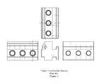
- FIG. 1is a cross-sectional schematic view of a typical fluid end showing its connection to a power section by stay rods. A plurality of fluid sections similar to that illustrated in FIG. 1 may be combined in a fluid end, as suggested in the Triplex fluid end housing schematically illustrated in FIG. 2 .
- Valve terminologyvaries according to the industry (e.g., pipeline or oil field service) in which the valve is used.
- the term “valve”means just the moving element or valve body.
- the term “valve”includes not only a valve body but also one or more valve guides to control the motion of the valve body, a valve seat, and a valve spring and spring retainer that tend to hold the valve closed (i.e., with the valve body reversibly sealed against the valve seat).
- Valve bodiestypically comprise guide means such as a crow-foot guide, a lower guide stem and/or a top guide stem for guiding the valve body as it moves between open and closed positions. Additionally, valve bodies typically include at least one seal retention groove for incorporating a peripheral element for sealing against a valve seat.
- FIG. 3schematically illustrates a cross-section of a web valve seat and a stem-guided valve body incorporating an elastomeric seal insert conventionally bonded within a seal retention groove.
- Conventional web-seat, stem-guided designswere proposed in the past to withstand the high pressures and repetitive impact loading typical of oil field service.
- Elastomeric seal tearing or crackingas schematically illustrated in FIG. 3 , extrusion of elastomer into the extrusion gap, and excessive wear of lower and/or top valve stem guides are among the common failure modes of these valves. Additional background, particularly on extrusion-related elastomer stress, can be found in U.S. Pat. No. 6,955,181 B1, incorporated herein by reference.
- elastomeric seal tearing or crackingtypically occurs during valve closure.
- Such seal damageoccurs in part because of high residual elastomer stress that develops due to shrinkage of the elastomer as it cures.
- the seal insertis conventionally bonded to the metal walls of the seal retention groove, elastomer near the bond cannot move appreciably when a cast-in-place seal insert shrinks during curing. In contrast, elastomer more distant from the bond is more free to move as it shrinks
- FIG. 5is a partial cross-section schematically illustrating discharge valve body 701 in its closed position (i.e., with elastomeric seal 703 held in symmetrical contact with valve seat 705 by discharge valve spring 707 ). Note that top guide stem 709 of discharge valve body 701 is aligned in close sliding contact with top valve stem guide 711 .
- FIG. 6schematically illustrates how misalignment of top guide stem 709 is possible with excessive wear of top valve stem guide 711 .
- Such excessive wearcan occur because discharge valve body 701 , including top guide stem 709 , is typically made of steel that has been carburized to a hardness of about 60 Rockwell C.
- the wall of top valve stem guide 711which is shown in FIG. 6 as being formed within discharge bore plug 713 , is typically made of mild alloy steel with a hardness of about 30 Rockwell C.
- the softer wall of stem guide 711is worn away by sliding contact with the harder guide stem 709 .
- This wearis accelerated by side loads on valve body 701 that result when fluid flowing past the valve body changes its direction of flow into the discharge manifold. Analogous side loads would be present on a suction valve when fluid flowing past the valve body changes its direction of flow into the plunger cavity.
- top valve stem guide 711can be worn sufficiently to allow discharge valve leakage due to significant asymmetric contact of elastomeric seal 703 with valve seat 705 as schematically illustrated in FIG. 7 .
- This problem of stem guide wearis typically addressed in practice through use of a replaceable bushing 715 having a modified top valve stem guide 711 ′ (see the schematic illustration in FIG. 8 ).
- Bushing 715is commonly made of a plastic such as urethane, or a wear and corrosion-resistant metal such as bronze. Such bushings require periodic checking and replacement, but these steps may be overlooked by pump mechanics until a valve fails prematurely.
- valve bodyrequires finish machining to closely match the dimensions of the seals.
- finish machiningcould be reduced or eliminated if elastomeric seals were cast and cured in place on the valve body (hereinafter “cast-in-place”). But savings in machining costs were often offset in practice by added costs associated with adhesive bonding of the cast-in-place seal inserts to a valve element in an attempt to increase overall valve body integrity (see the '995 patent, col 7, lines 47-50).
- the inventionextends the service life of valves by incorporating specially formed elastomeric elements such as valve seals and/or guide stem sleeves as described herein.
- Elastomeric elements as described hereincomprise elastomers (e.g., resilient materials having a modulus less than that of mild steel), and may additionally comprise one or more components that impart or enhance a desirable property (e.g., lubricant(s) and/or lubricant element(s) for reducing a coefficient of friction).
- valve body and seal assemblyas described herein comprises at least one elastomeric element.
- certain valve body and seal assembly embodimentsmay comprise at least one elastomeric element having at least one lubricant element partially embedded in it and/or at least one lubricant otherwise incorporated in it.
- a lubricant elementif present, may in turn be cross-linked to one or more elastomeric elements to which it may be adjacent.
- a first embodiment of the inventioncomprises a method of making a valve body and seal assembly.
- the methodcomprises providing a longitudinally symmetrical valve body comprising a seal retention groove and a frusto-conical valve body impact area for contacting a valve seat.
- the methodthen comprises providing a mold reversibly fitted to the longitudinally symmetrical valve body to facilitate subsequent casting steps.
- the methodfurther comprises symmetrically casting a first elastomer (e.g., a polyurethane) in the seal retention groove to form a first seal section having a first frusto-conical seal portion for sealing against a valve seat.
- the frusto-conical valve body impact areais central to and geometrically similar to the first frusto-conical seal portion.
- the methodfurther comprises partially curing the first elastomer, followed by symmetrically casting a second elastomer (e.g., a polyurethane) in the seal retention groove to form a second seal section having a second frusto-conical seal portion for sealing against a valve seat.
- a second elastomere.g., a polyurethane
- the first frusto-conical seal portionis centrally adjacent to and geometrically similar to said second frusto-conical seal portion.
- a final stepincludes crosslinking and curing the first elastomer and the second elastomer to make a valve body and seal assembly. The mold may then be separated from the valve body and seal assembly.
- frusto-conical portions of both the first and second symmetrically cast seal sectionsfunction by sealing against a valve seat.
- the first frusto-conical seal portionis centrally adjacent to and geometrically similar to the second frusto-conical seal portion, and the shapes and/or physical properties of the first and second seal sections may differ in a predetermined manner.
- the first seal sectionmay have a greater modulus than the second seal section to better cushion the impact forces of rapid valve closure.
- the coefficient of friction of the first seal section on a valve seatmay differ from the coefficient of friction of the second seal section on the same valve seat so as to minimize seal wear.
- first and second seal sectionsmay be shaped to beneficially distribute the impact forces of rapid valve closure through the seal sections to predetermined portions of the valve body on which the seal sections are cast.
- the lubricant element embodiments shown schematically in FIGS. 14A-Fsignificantly reduce the buildup of residual elastomer seal stress during curing (described above with reference to FIG. 3 ).
- the inventionreduces seal elastomer stress, and thus cracking, in the region near the extrusion gap (see FIG. 3 ).
- the conventional elastomer-metal bond schematically shown in FIG. 3is absent.
- a lubricant elementis present, a portion of the lubricant element being crosslinked to the seal elastomer.
- a lubricant elementis typically relatively non-rigid (compared to the metal of the walls of the seal retention groove), such a lubricant element is relatively free to shrink along with the curing seal elastomer to which it is crosslinked.
- residual elastomer stress in the cured seal insertis typically lower in the illustrated invention embodiments of FIGS. 14A-F than in conventionally bonded seal inserts.
- exacerbation of seal elastomer stress during valve operationis also reduced as a result of relatively lower frictional drag forces arising as a lubricant element slides relatively easily over the valve seat.
- a lubricant elementcan function to reduce extrusion stress in seal elastomers.
- Lubricant elementscomprise at least one commercially-available polymer (e.g., polyamide) and at least one lubricant (e.g., molybdenum disulfide and/or graphite), the polymer being cross-linkable with an elastomeric element when partially embedded therein.
- a lubricant elementtypically has a higher modulus of elasticity than the elastomeric element with which it is crosslinked, and such a lubricant element can function as an anti-extrusion device as described herein.
- Lubricant elementsalso tend to reduce sliding friction and wear during valve operation.
- elastomeric elementsallow small displacements of lubricant elements to which they are crosslinked, while substantially maintaining the lubricant elements' friction-reducing, wear-reducing, and/or anti-extrusion functions.
- the inventionaddresses both the problem of premature valve failures due to tearing or cracking of an elastomeric cast-in-place seal insert and the problem of excessive wear of valve stem guides.
- the problem of excessive wear of valve stem guidesapplies particularly to applications of top-stem-guided valve bodies because of the absence of the stabilizing influence of a lower guide stem.
- the amount of such limited relative movementis an inverse function of the modulus of elasticity for each elastomer selected and an inverse function of any adhesion between each elastomer and the valve body.
- an elastomer's microstructureand physical properties such as modulus of elasticity, strengths and stiffnesses may not be fixed but may instead be functions of the stresses to which the elastomer has been exposed (e.g., mechanical, thermal and/or chemical stress).
- the inventionincludes methods of making a valve body and seal assembly, valve body and seal assemblies made by such methods, and valves comprising such valve body and seal assemblies.
- Elastomeric elements cast-in-place according to the inventionexperience relatively lower stress due to limited relative movement between the valve body and the elastomer(s).
- One such methodcomprises providing a castable elastomer (comprising, for example, urethane) and a valve body on which the elastomer is cast-in-place.
- the valve bodyhas a longitudinal axis and comprises a seal retention groove spaced apart from the longitudinal axis.
- the seal retention groovehas first and second opposing sides, the opposing sides being separated by a groove width.
- a top guide stemextends away from the seal retention groove along the longitudinal axis, and an impact area of the valve body for contacting a valve seat is proximate to (i.e., is relatively close to or intersects) the first opposing side of the seal retention groove.
- a transition areamay be smoothed between the first opposing side of the seal retention groove and an impact area of the valve body to eliminate or reduce stress risers in this area.
- a moldfor containing the castable elastomer, the mold comprising a mold shell mated with the valve body.
- the mold in this embodimentcomprises the adhesion-inhibiting seal retention groove and the adhesion-inhibiting top guide stem.
- the castable elastomeris poured into the mold and cured in the mold, after which the mold shell is removed from the valve body to make a valve body and seal assembly.
- first and second moldsare provided for containing the castable elastomer, the first and second molds comprising, respectively, an adhesion-inhibiting first mold shell mated with the valve body and an adhesion-inhibiting second mold shell mated with the valve body.
- the first moldis for a cast-in-place elastomeric seal insert in a seal retention groove and comprises the first mold shell and the valve body's adhesion-inhibiting seal retention groove.
- the second moldis for a cast-in-place elastomeric top guide stem sleeve and comprises the second mold shell and at least a portion of the adhesion-inhibiting top guide stem.
- First and second castable elastomers(which may be the same or different) are poured into the first and second molds respectively and cured in these molds, after which the first and second mold shells are removed from the valve body to make a valve body and seal assembly.
- the first and second moldsare combined into one mold comprising a mold shell mated with the valve body.
- This combined moldis for both an elastomeric seal insert in a seal retention groove and an elastomeric top guide stem sleeve and comprises both the adhesion-inhibiting seal retention groove and at least a portion of the adhesion-inhibiting top guide stem.
- a castable elastomeris poured into and cured within the combined mold, after which the mold shell is removed from the valve body to make a valve body and seal assembly.
- the above methods for forming elastomeric elementsmay comprise additional steps for placement of at least one lubricant element in a mold so that when an elastomer is poured and cured in the mold (i.e., a castable elastomer), a portion of the lubricant element is embedded in the resulting elastomeric element.
- Lubricant elementscomprise at least one commercially-available polymer (e.g., polyamide) and at least one lubricant (e.g., molybdenum disulfide and/or graphite), the polymer being cross-linkable with a cured elastomeric element when embedded therein.
- a portion of a circular lubricant elementmay be embedded proximate to the first opposing groove wall and to the impact area of a valve body.
- the circular lubricant elementmay have, for example, a generally washer shape (i.e., resembling a Belleville washer), or a generally frusto-conical or cylindrical shape.
- a castable elastomer for such applicationswould be chosen from commercially available elastomers known to crosslink during curing with the lubricant element polymer (e.g., a poly(vinyl-acetate-ethylene) material such as Polymer Products Inc. black compound P-395). Note that such crosslinking generally increases with increasing temperature. Heat may thus be added in one or more steps in the above methods (e.g., during curing of the castable elastomer and/or by preheating the lubricant element).
- At least one cylindrical lubricant elementmay be incorporated in a mold in a position surrounding at least a portion of a top stem guide elastomeric element in the form of a sleeve.
- a portion of the cylindrical lubricant elementis crosslinked with the top stem guide sleeve.
- lubricant elementstend to reduce sliding friction and wear during valve operation, and the elastomeric elements in which the lubricant elements are partially embedded allow small displacements of the lubricant elements while substantially maintaining their friction-reducing and wear-reducing functions.
- a lubricant elementmay thus move relatively small distances with respect to a valve body on which it operates, it remains relatively stable because of the relative stability of the elastomeric element to which it is crosslinked.
- elastomeric elements with respect to a valve bodyFor applications herein, relative stability of elastomeric elements with respect to a valve body is addressed in methods of securing an elastomeric seal insert and a top guide stem sleeve on a valve body that comprises a top guide stem and a seal retention groove having first and second opposing sides.
- One such methodcomprises providing one or more circular serrations on the first and/or second opposing groove sides and providing a mold for making an elastomeric seal insert and a top guide stem sleeve, the mold comprising the seal retention groove and at least a portion of the top guide stem.
- first and second moldsare provided for making an elastomeric seal insert in a seal retention groove and an elastomeric top guide stem sleeve respectively, the first mold comprising the seal retention groove and the second mold comprising at least a portion of the top guide stem.
- the modified methodthen allows the use of first and second castable elastomers (which may be different) for casting and curing in the first and second molds respectively to make an adhesion-inhibiting elastomeric seal insert and a top guide stem sleeve and secure them on a valve body.
- the valve bodyis subsequently separated from the first and second molds.
- these methodsmay be modified by additional steps relating to embedding portions of one or more lubricant elements and crosslinking these elements to the elastomer in which they are partially embedded.
- Provision for limited relative movement of cast-in-place elastomers in the illustrated embodiments of the inventionobviates shortcomings in past designs related to adhesively bonding or otherwise fixing cast-in-place elastomers to a valve body.
- Such past designsdid not allow limited relative elastomer movement in response to localized dynamic compressive, bending and/or shear loads, nor did these designs account for deleterious effects of an increase in background stress as the elastomer cured and shrank away from portions of a valve body to which it was bonded or otherwise fixed. This increased background and dynamic elastomer stress shortened valve service life because it predisposed the elastomer to cracking and tearing.
- Elastomeric valve seal inserts and guide stem sleeves cast-in-place on valve bodies according to the inventiondiffer materially from prior elastomers cast-in-place on valve bodies due to the inhibition of adhesion (including the absence of bonding) between the elastomer and the valve body, resulting in materially lower levels of background and dynamic stress in the cured elastomer.
- Such stress reductionwhich includes reduction of peak contact pressures, with dissipation of impact energy within the elastomer of seal inserts and guide stem sleeves, significantly extends the service life of both the seal inserts and valve stem guides.
- a cast-in-place seal insertmay experience limited relative movement with respect to the seal retention groove of that valve body.
- Groove wall serrationswhen used to assist in retaining the seal insert in the peripheral groove during its limited relative movement, may be offset as described below to minimize their effects as stress raisers for either the seal retention groove walls or the elastomer of the cast-in-place seal insert. Such serration placement minimizes valve body fatigue failures due to impact loads and bending stress.
- serrationsmay be designed so the seal insert elastomer experiences continued effective contact with the serrations on the groove walls notwithstanding the combined effects of elastomer shrinkage during curing and limited relative movement of the seal insert with respect to the serrations during valve operation. Such continued effective contact (i.e., interdigitation) ensures that the seal insert is retained in its peripheral groove without suffering displacement that would materially reduce its service life.
- FIG. 1is a cross-sectional schematic view of a typical plunger pump fluid section showing its connection to a power section by stay rods.
- FIG. 2schematically illustrates a conventional Triplex plunger pump fluid section housing.
- FIG. 3schematically illustrates a partial cross-section of a web valve seat and a corresponding stem-guided valve body showing areas of common failure modes of cast-in-place elastomeric seals that are bonded to a valve body.
- FIG. 4Aschematically illustrates a cross-section of a plunger pump that includes a top-stem-guided suction valve and a top-stem-guided discharge valve.
- FIG. 4Bschematically illustrates the sectional view labeled B-B in FIG. 4A .
- FIG. 5is a partial cross-section schematically illustrating detail of the top-stem-guided discharge valve of FIGS. 4A and 4B .
- FIG. 6schematically illustrates misalignment of the top guide stem of the discharge valve of FIG. 5 .
- FIG. 7schematically illustrates improper closure of the discharge valve of FIG. 6 due to misalignment of the top guide stem.
- FIG. 8schematically illustrates a replaceable bushing in a modification of the top valve stem guide shown in FIG. 7 .
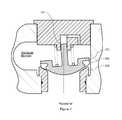
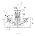
- FIG. 9schematically illustrates an embodiment of a top-stem-guided valve body having a cast-in-place elastomeric seal insert and a separate cast-in-place top guide stem sleeve made according to the invention.
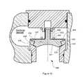
- FIG. 10schematically illustrates an embodiment of a top-stem-guided valve body having a cast-in-place elastomeric seal insert and an integral cast-in-place top guide stem sleeve made according to the invention.
- FIG. 11schematically illustrates a cross-section showing a top-stem-guided valve body and a first mold shell for casting-in-place an elastomeric seal insert in the valve body's seal retention groove, together with a second mold shell for casting-in-place a sleeve on the valve body's top guide stem, the seal retention groove, the top guide stem, and the first and second mold shells comprising adhesion-inhibiting surfaces.
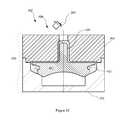
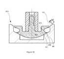
- FIG. 12schematically illustrates a cross-section showing a top-stem-guided valve body and a mold shell for casting-in-place an elastomeric seal insert in the valve body's seal retention groove and an integral sleeve on the valve body's top guide stem, the seal retention groove, the top guide stem, and the mold shell comprising adhesion-inhibiting surfaces.
- FIG. 13Aschematically illustrates a partial cross-section showing detail of a top-stem-guided discharge valve body in a plunger pump, the valve body having a cast-in-place elastomeric seal insert in a seal retention groove and a cast-in-place sleeve on the top guide stem.
- FIG. 13Bschematically illustrates the partial cross-section B-B indicated in FIG. 13A , cross-section B-B showing longitudinal fluid flow channels in the top guide stem sleeve.
- FIG. 14Aschematically illustrates a partial cross-section of a valve body and seal assembly 999 , together with first and second molds.
- FIG. 14Bschematically illustrates a magnified section of the circular lubricant element shown in FIG. 14A which has a generally frusto-conical shape and which is partially embedded in an elastomeric element.
- FIG. 14Cschematically illustrates a circular lubricant element having a generally cylindrical shape which is partially embedded in an elastomeric element.
- FIG. 14Dschematically illustrates a magnified section of the circular lubricant element having a generally cylindrical shape which is shown in FIG. 14C .
- FIG. 14Eschematically illustrates a generally washer-shaped circular lubricant element which is partially embedded in an elastomeric element.
- FIG. 14Fschematically illustrates a magnified section of the generally washer-shaped circular lubricant element which is shown in FIG. 14E .
- FIG. 15schematically illustrates a partial cross-section of a valve body and seal assembly 999 ′ analogous-in-part to that shown in FIG. 14A but showing casting of a first seal section in a seal retention groove.
- FIG. 16schematically illustrates a partial cross-section of a valve body and seal assembly 999 ′′ analogous-in-part to that shown in FIG. 15 but showing casting of a second seal section in a seal retention groove.
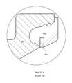
- FIG. 17schematically illustrates a magnified section analogous-in-part to that of FIG. 14F but showing an elastomeric seal comprising first and second seal sections cast in a seal retention groove.
- FIG. 9An illustrated embodiment of a top-stem-guided valve body having a cast-in-place elastomeric seal insert and a separate cast-in-place top guide stem sleeve made according to the invention is shown in FIG. 9 .
- the elastomeric seal insertis cast-in-place in a first mold comprising a seal retention groove of a valve body that comprises at least one such groove, while the top guide stem sleeve is cast-in-place in a second mold comprising at least a portion of the top guide stem of the valve body.
- FIG. 10An illustrated alternative embodiment of a top-stem-guided valve body having a cast-in-place elastomeric seal insert and an integral cast-in-place top guide stem sleeve made according to the invention is shown in FIG. 10 .
- the elastomeric seal insert and the elastomeric top guide stem sleeveare cast-in-place in a single mold comprising both a valve body's seal retention groove and the valve body's top guide stem.
- mold surfaces coming into contact with the elastomer as a seal insert and/or a top guide stem sleeve is cast-in-placeare chosen and/or prepared so as to inhibit adhesion of the elastomer to each such surface.
- Adhesion-inhibiting properties of a mold-elastomer interfacemay be obtained by appropriate choice of materials for the mold and the elastomer, and/or by subsequent treatment of these materials. For example, if a valve body is quenched in oil after heat-treatment (e.g., carburization), a thin layer of the quenching oil may be retained on the seal retention groove after quenching is completed for treating the groove to increase its adhesion-inhibiting properties.
- An adhesion-inhibiting seal retention groovemay also be prepared, for example, by polishing the groove and/or by the applying to the groove one or more layers of non-stick materials such as oils, greases, waxes or plastics having non-stick properties analogous to those of Teflon®.
- non-stick materialssuch as oils, greases, waxes or plastics having non-stick properties analogous to those of Teflon®.
- an elastomeric seal cast-in-place in contact with a mold having adhesion-inhibiting surfacesexhibits minimal or no adherence to such surfaces during curing. That is, forces due to adhesion of the elastomer to mold surfaces, if present, will not materially add to the elastomer's background stress and thus will not materially reduce service life through a mechanism similar to that schematically illustrated in FIG. 3 .
- valve body and seal assembly 699that is schematically illustrated in FIG. 9 comprises a top-stem-guided valve body 601 having a cast-in-place elastomeric seal insert 603 and a separate cast-in-place top guide stem sleeve 623 secured to valve body 601 according to a method of the invention.
- Elastomeric seal insert 603is cast-in-place in a seal retention groove 633 having first and second opposing groove sides 635 and 637 respectively, while guide stem sleeve 623 is cast-in-place on top guide stem 609 .
- top guide stem 609comprises an undercut 643 having a chamfered superior wall 645 for further securing guide stem sleeve 623 to top guide stem 609 while allowing limited relative movement of guide stem sleeve 623 with respect to top guide stem 609 .
- Guide stem sleeve 623is additionally secured to top guide stem 609 by an ambient pressure greater than zero because the close fit of guide stem sleeve 623 on top guide stem 609 does not admit air or liquid between them.
- the method of securing an elastomeric seal insert 603 and a top guide stem sleeve 623 on valve body 601 of the illustrated embodimentcomprises providing circular serrations 636 on first opposing groove side 635 and circular serrations 638 on second opposing groove side 637 .
- FIG. 11schematically shows that a first mold 513 is provided comprising the seal retention groove 633 , and a second mold 533 is provided comprising at least a portion of the top guide stem 609 . At least one castable elastomer is chosen that will not adhere to first mold 513 or second mold 533 .
- FIG. 11schematically shows that a first mold 513 is provided comprising the seal retention groove 633 , and a second mold 533 is provided comprising at least a portion of the top guide stem 609 . At least one castable elastomer is chosen that will not adhere to first mold 513 or second mold 533 .
- castable elastomer 301is cast and cured in first mold 513 to secure elastomeric seal insert 603 on valve body 601 , while a different castable elastomer 302 is cast and cured in second mold 533 to secure top guide stem sleeve 623 on valve body 601 .
- Valve body 601is then separated from first mold 513 and second mold 533 .
- castable elastomer 301may be chosen to have one or more properties (e.g., greater compliance) different from those of castable elastomer 302 because of the different stresses to which peripheral seal inserts and guide stem sleeves are exposed in use.
- a cast-in-place elastomer seal insert 603 and guide stem sleeve 623 secured to a valve body 601 as described aboveexperience relatively lower stress due to limited relative movement between the valve body 601 and the elastomer(s) in use.
- An alternative method of making a valve body and seal assembly 499comprises providing a castable elastomer 303 (see FIG. 12 ) and a valve body 401 on which the elastomer is cast-in-place.
- the valve body 401has a longitudinal axis and comprises a seal retention groove 433 spaced apart from the longitudinal axis.
- valve body 401comprises a partially concave lower surface 421 , in contrast to the convex lower surface 621 of valve body 601 (see FIG. 9 ).
- Concave lower surface 421facilitates reducing the mass of valve body 401 without significant loss of valve body strength.
- seal retention groove 433has first and second opposing sides 435 and 437 respectively, opposing sides 435 and 437 being separated by a groove width.
- a top guide stem 409extends away from seal retention groove 433 along the longitudinal axis, and an impact area 431 of the valve body for contacting a valve seat is proximate to the first opposing side 435 of the seal retention groove 433 .
- the methodincludes treating seal retention groove 433 and top stem guide 409 to render seal retention groove 433 and top guide stem 409 adhesion-inhibiting.
- treating top surface 404 of valve body 401 to render it adhesion-inhibitingmay be included in the method, but such treatment may be eliminated because elastomer overlying top surface 404 is locally compressed by valve spring 407 .
- a mold 202is provided for containing castable elastomer 303 , mold 202 comprising mold shell 203 (shown in FIG. 12 as comprising upper mold shell section 263 and lower mold shell section 273 ) mated with valve body 401 .
- the mold 202comprises the adhesion-inhibiting seal retention groove 433 and the adhesion-inhibiting top guide stem 409 for making a valve body and seal assembly having an elastomeric seal insert 403 in a seal retention groove integral with an elastomeric top guide stem sleeve 423 on a top guide stem.
- Castable elastomer 303is poured into mold 202 and cured in mold 202 to achieve a cross-linked elastomer, after which mold shell 203 is removed to make a valve body and seal assembly 499 .
- mold 202can be replaced by two separate molds such as mold 513 and mold 533 (see FIG. 11 ) for making a valve body and seal assembly having an elastomeric seal insert in a seal retention groove separate from an elastomeric top guide stem sleeve on a top guide stem.
- FIG. 11shows that mold 513 comprises mold shell 503 and adhesion-inhibiting seal retention groove 633
- mold 533comprises mold shell 523 and at least a portion of adhesion-inhibiting top guide stem 609 .
- Castable elastomer 301is poured into mold 513 and cured in mold 513 to achieve a cross-linked elastomeric seal insert, and castable elastomer 302 is poured into mold 533 and cured in mold 533 to achieve a cross-linked elastomeric top guide stem sleeve. Then mold shell 503 and mold shell 523 are removed to make a valve body and seal assembly 699 .
- FIG. 13Aschematically illustrates a partial cross-section showing detail of a top-stem-guided discharge valve body 601 ′ in a plunger pump.
- Valve body 601 ′has a cast-in-place elastomeric seal insert 603 in a seal retention groove 633 and a cast-in-place sleeve 623 ′ on the top guide stem 609 ′.
- top guide stem 609(see FIG. 9 ) comprises an undercut 643
- top guide stem 609 ′ in FIG. 13has no undercut.
- Cast-in-place sleeve 623 ′is secured on top guide stem 609 ′ by ambient pressure greater than zero as described above.
- FIG. 13Bschematically illustrates the partial cross-section B-B indicated in FIG. 13A , cross-section B-B showing longitudinal fluid flow channels 655 molded into top guide stem sleeve 623 ′.
- At least one longitudinal fluid flow channel 655allows escape of fluid that may be present in top stem guide 611 as top guide stem 609 ′ within top guide stem sleeve 623 ′ advances into top stem guide 611 within discharge bore plug 613 .
- longitudinal fluid flow channelsneed not be straight as schematically illustrated herein, but may instead have a curved (e.g., spiral or helical) shape, as long as the channel(s) allow longitudinal fluid flow (i.e., the escape of fluid from the top stem guide as described above).
- FIG. 14Aschematically illustrates a partial cross-section of a valve body and seal assembly 999 , together with first mold 813 and second mold 833 .
- First mold 813comprises seal retention groove 933 having first and second opposing sides (i.e., groove walls) 935 and 937 respectively.
- First opposing groove wall 935is proximate to valve body impact area 931 of valve body 901 .
- Second mold 833comprises at least a portion of top guide stem 909 (an embodiment of guide means) of valve body and seal assembly 999 .
- Surfaces of molds 813 and 833 that are intended to contact castable elastomersare adhesion-inhibiting surfaces.
- Castable elastomers 101 and 102 shown being poured into molds 813 and 833 respectivelymay be the same or different.
- Such castable elastomersmay be chosen from commercially available elastomers capable of crosslinking with a polymer component of the respective lubricant element 951 , 953 , 955 and/or 957 intended to be partially embedded in them when cured.
- Lubricant element 951shown in schematic cross-section in FIG. 14A and in a magnified section in FIG. 14B , is a circular lubricant element having a generally frusto-conical shape which is partially embedded in elastomeric element 903 .
- Lubricant element 953also shown in schematic cross-section in FIG. 14A , is a circular lubricant element having a generally cylindrical shape and functioning as a portion of guide stem sleeve 923 .
- Lubricant element 955shown in schematic cross-section in FIG. 14C and in a magnified section in FIG. 14D , is a circular lubricant element having a generally cylindrical shape which is partially embedded in elastomeric element 903 ′.
- Lubricant element 957shown in schematic cross-section in FIG. 14E and in a magnified section in FIG. 14F , is a generally washer-shaped circular lubricant element which is partially embedded in elastomeric element 903 ′′.
- FIGS. 15-17schematically illustrate a method of making a valve body and seal assembly 999 ′ comprising a valve body 901 and seal 983 .
- the methodcomprises providing a mold 813 ′ reversibly fitted as shown (see FIGS. 15 and 16 ) to a longitudinally symmetrical valve body 901 .
- Valve body 901comprises a seal retention groove 973 and a frusto-conical valve body impact area 931 for contacting a valve seat.
- the methodfurther comprises symmetrically casting a first elastomer 103 in seal retention groove 973 to form a first seal section 959 of seal 983 having a first frusto-conical seal portion 961 for sealing against a valve seat (see FIG. 15 ).
- frusto-conical valve body impact area 931is central to and geometrically similar to first frusto-conical seal portion 961 .
- the method schematically illustrated in FIGS. 15-17further comprises partially curing first elastomer 103 after it is cast in the shape of first seal section 959 , followed by symmetrically casting a second elastomer 104 in seal retention groove 973 to form a second seal section 903 ′′′ of seal 983 having a second frusto-conical seal portion 971 for sealing against a valve seat (see FIG. 16 ).
- first frusto-conical seal portion 961is centrally adjacent to and geometrically similar to second frusto-conical seal portion 971 .
- a final stepincludes crosslinking and curing first elastomer 103 (in the shape of first seal section 959 ) and second elastomer 104 (in the shape of second seal section 903 ′′′) in one or more areas where the seal sections are in contact (i.e., along intra-seal interface 981 as seen, e.g., in FIG. 17 ) to make a valve body and seal assembly 999 ′. Mold 813 ′ may then be separated from valve body and seal assembly 999 ′.
- first seal section 959may comprise polyurethane of about 95 durometer Shore A hardness to about 60 durometer Shore D hardness to resist seal extrusion and/or to absorb and redistribute impact forces due to valve closure.
- second seal section 903 ′′′may comprise polyurethane of about 75 to about 85 durometer Shore A hardness to facilitate valve sealing on closure and to aid redistribution of impact forces due to valve closure.
- First seal section 959may additionally comprise at least one lubricant (e.g., graphite and/or molybdenum disulfide) to reduce shear forces and seal extrusion on valve closure.
- lubricante.g., graphite and/or molybdenum disulfide
- Lubricant elements 951 , 955 and 957can function to resist extrusion of elastomeric elements 903 , 903 ′ and 903 ′′ respectively when the lubricant elements have a higher modulus of elasticity than the respective elastomeric elements.
- These extrusion-resistance functions of partially embedded and crosslinked lubricant elementsare not found in older valve designs. Rather, resistance to extrusion was provided in older valve designs by, for example, a bond between a cast-in-place elastomeric seal insert and a relatively rigid anti-extrusion ring and/or a seal retention groove wall.
- a lubricant element of the inventionis relatively non-rigid and also crosslinked to an elastomeric element in which it is partially embedded, the lubricant element can be somewhat deformed by shrinkage of the embedding elastomer during curing. Such deformation of the lubricant element tends to reduce the harmful residual curing stresses that occurred previously when a cast-in-place elastomer was bonded to a rigid anti-extrusion ring or a seal retention groove wall. And with lowered residual curing stress in a peripheral valve seal, valve service life may be extended.
- first opposing groove walls on valve bodies of the inventionare closer than second opposing walls to an area of high impact loads because they are closer to a peripheral metal sealing surface (i.e., an impact area) on the valve body.
- a peripheral metal sealing surfacei.e., an impact area
- Second opposing groove wallswhile more distant from the site of maximum metal-to-metal impact stress than first opposing walls, nevertheless experience significant bending stress due to forces transmitted to them through the seal insert elastomer.
- This bending stress on the second opposing groove wallis lowest peripherally and highest centrally (i.e., highest in that part of the wall that is closest to the longitudinal axis of the valve body).
- the area of maximum bending stress on second opposing groove wallsis more central than the area of maximum metal-to-metal impact stress on first opposing walls because second opposing walls are effectively cantilevered peripherally from the most centrally located area of the seal retention groove.
- first opposing groove wallsare preferably located as far centrally on such groove walls as practicable to maximize the distance from the impact area and thus minimize stress build-up near the serrations (which act as stress raisers).
- This relatively central locationalso provides clearance between the serrations and a frusto-conical lubricant element such as 951, which may be located more peripherally (i.e., proximate to the first opposing groove wall and the impact area of a valve body).
- serrations on second opposing wallsare located as far as practicable from the longitudinal axis of symmetry (i.e., peripherally, relative to the centrally-placed serrations on the first opposing walls as noted above).
- Serrations on first and second groove wallsare thus offset. Serration offset, in turn, minimizes the detrimental stress-raising effects of the serrations on their respective valve body flange areas.
- use of offset serrationsmeans that retaining forces exerted on an elastomeric seal in a groove by serrations on the opposing groove walls are further spaced apart as a function of the offset distance. This further spacing apart adds to the separation of forces acting on the seal insert and thus tends to allow limited relative movement of the seal insert with respect to the groove walls without excessive elastomer stress.
- the offset serrations in a seal retention groove of the inventionact to reduce the likelihood of fatigue failures in valve body flanges, and they simultaneously reduce stress concentration in the elastomer of a seal in the groove.
- the latter benefitmay be further increased if spacing between the respective flange areas that form the opposing walls of a seal retention groove increases as a function of increasing distance from the valve body longitudinal axis. Spacing between seal retention groove walls is determined in part by industry standards but may diverge peripherally in valve bodies of the invention to obtain additional elastomer stress relief.
- Elastomer stressmay also be reduced when provision is made for escape of air or gas bubbles that may be present during casting of an elastomeric seal insert and/or an elastomeric guide stem sleeve in a mold comprising portions of a valve body when the longitudinal axis of the valve body is in the vertical orientation.
- escape of the air bubblesis facilitated by the presence of a superior chamfered wall on any guide stem undercut that may be present.
- escape of the air bubblesis facilitated if the groove width increases as a function of increasing distance from the valve body longitudinal axis.
- a desirable amount of groove width increase with increasing distance from the valve body longitudinal axismay be specified in terms of the included angle measured between straight (or nearly straight) portions of seal retention groove walls.
- the preferred range of these included angles for the inventionis about 10 to 60 degrees, depending on the particular valve body design.
- curvature of groove walls toward the center of the grooveis allowable if the resulting curved wall would not trap air bubbles in castable elastomer when the valve body is in position for casting of a seal in the groove. Included angle measurements for any curved portion of the groove wall may be made using the chord of any such curved portion.
Landscapes
- Engineering & Computer Science (AREA)
- General Engineering & Computer Science (AREA)
- Mechanical Engineering (AREA)
- Sealing With Elastic Sealing Lips (AREA)
Abstract
Description
Claims (18)
Priority Applications (1)
| Application Number | Priority Date | Filing Date | Title |
|---|---|---|---|
| US13/899,112US9291274B1 (en) | 2001-04-16 | 2013-05-21 | Valve body and seal assembly |
Applications Claiming Priority (6)
| Application Number | Priority Date | Filing Date | Title |
|---|---|---|---|
| US83604301A | 2001-04-16 | 2001-04-16 | |
| US10/179,804US6955181B1 (en) | 2001-04-16 | 2002-06-25 | Valve body and seal assembly |
| US11/148,081US7168440B1 (en) | 2002-06-25 | 2005-06-08 | Valve body and seal assembly |
| US56712706A | 2006-12-05 | 2006-12-05 | |
| US47239909A | 2009-05-27 | 2009-05-27 | |
| US13/899,112US9291274B1 (en) | 2001-04-16 | 2013-05-21 | Valve body and seal assembly |
Related Parent Applications (1)
| Application Number | Title | Priority Date | Filing Date |
|---|---|---|---|
| US47239909ADivision | 2001-04-16 | 2009-05-27 |
Publications (1)
| Publication Number | Publication Date |
|---|---|
| US9291274B1true US9291274B1 (en) | 2016-03-22 |
Family
ID=55488275
Family Applications (1)
| Application Number | Title | Priority Date | Filing Date |
|---|---|---|---|
| US13/899,112Expired - Fee RelatedUS9291274B1 (en) | 2001-04-16 | 2013-05-21 | Valve body and seal assembly |
Country Status (1)
| Country | Link |
|---|---|
| US (1) | US9291274B1 (en) |
Cited By (42)
| Publication number | Priority date | Publication date | Assignee | Title |
|---|---|---|---|---|
| US20170002947A1 (en)* | 2015-07-02 | 2017-01-05 | S.P.M. Flow Control, Inc. | Valve for Reciprocating Pump Assembly |
| US9631739B2 (en)* | 2015-01-27 | 2017-04-25 | Black Horse Llc | Valve and seat assembly for a high pressure pump |
| US20180283568A1 (en)* | 2016-05-16 | 2018-10-04 | Sumitomo Metal Mining Co., Ltd. | Cone valve |
| US20190101109A1 (en)* | 2017-10-02 | 2019-04-04 | S.P.M. Flow Control, Inc. | Valve stop |
| US10711778B2 (en)* | 2017-04-18 | 2020-07-14 | St9 Gas And Oil, Llc | Frac pump valve assembly |
| US11353117B1 (en) | 2020-01-17 | 2022-06-07 | Vulcan Industrial Holdings, LLC | Valve seat insert system and method |
| US11384756B1 (en) | 2020-08-19 | 2022-07-12 | Vulcan Industrial Holdings, LLC | Composite valve seat system and method |
| US11391374B1 (en) | 2021-01-14 | 2022-07-19 | Vulcan Industrial Holdings, LLC | Dual ring stuffing box |
| US11415229B2 (en)* | 2018-07-19 | 2022-08-16 | Gea Tuchenhagen Gmbh | Lifting valve and seal |
| US11421679B1 (en) | 2020-06-30 | 2022-08-23 | Vulcan Industrial Holdings, LLC | Packing assembly with threaded sleeve for interaction with an installation tool |
| US11421680B1 (en) | 2020-06-30 | 2022-08-23 | Vulcan Industrial Holdings, LLC | Packing bore wear sleeve retainer system |
| US20220268362A1 (en)* | 2019-10-25 | 2022-08-25 | Spm Oil & Gas Inc. | Wear-resistant hydraulic fracturing pump valves |
| US11434900B1 (en) | 2022-04-25 | 2022-09-06 | Vulcan Industrial Holdings, LLC | Spring controlling valve |
| US11448210B2 (en) | 2015-07-02 | 2022-09-20 | Spm Oil & Gas Inc. | Valve for reciprocating pump assembly |
| US11560884B2 (en) | 2019-11-18 | 2023-01-24 | Kerr Machine Co. | Fluid end |
| US11578711B2 (en) | 2019-11-18 | 2023-02-14 | Kerr Machine Co. | Fluid routing plug |
| US11578710B2 (en) | 2019-05-02 | 2023-02-14 | Kerr Machine Co. | Fracturing pump with in-line fluid end |
| USD980876S1 (en) | 2020-08-21 | 2023-03-14 | Vulcan Industrial Holdings, LLC | Fluid end for a pumping system |
| US20230101730A1 (en)* | 2020-02-25 | 2023-03-30 | Rotarex S.A. | Closing member of a gas valve for very high pressure |
| US11635068B2 (en) | 2019-11-18 | 2023-04-25 | Kerr Machine Co. | Modular power end |
| US11644018B2 (en) | 2019-11-18 | 2023-05-09 | Kerr Machine Co. | Fluid end |
| USD986928S1 (en) | 2020-08-21 | 2023-05-23 | Vulcan Industrial Holdings, LLC | Fluid end for a pumping system |
| US11686296B2 (en) | 2019-11-18 | 2023-06-27 | Kerr Machine Co. | Fluid routing plug |
| USD997992S1 (en) | 2020-08-21 | 2023-09-05 | Vulcan Industrial Holdings, LLC | Fluid end for a pumping system |
| US11808254B2 (en) | 2019-11-18 | 2023-11-07 | Kerr Machine Co. | Fluid end assembly |
| US11808364B2 (en) | 2021-11-11 | 2023-11-07 | Kerr Machine Co. | Valve body |
| US20240003345A1 (en)* | 2020-11-25 | 2024-01-04 | Victrex Manufacturing Limited | Linear compressor discharge valves |
| US11920583B2 (en) | 2021-03-05 | 2024-03-05 | Kerr Machine Co. | Fluid end with clamped retention |
| US11920684B1 (en) | 2022-05-17 | 2024-03-05 | Vulcan Industrial Holdings, LLC | Mechanically or hybrid mounted valve seat |
| US11946465B2 (en) | 2021-08-14 | 2024-04-02 | Kerr Machine Co. | Packing seal assembly |
| US12018662B2 (en) | 2019-11-18 | 2024-06-25 | Kerr Machine Co. | High pressure pump |
| US12049889B2 (en) | 2020-06-30 | 2024-07-30 | Vulcan Industrial Holdings, LLC | Packing bore wear sleeve retainer system |
| US12055221B2 (en) | 2021-01-14 | 2024-08-06 | Vulcan Industrial Holdings, LLC | Dual ring stuffing box |
| US12140240B1 (en) | 2022-01-19 | 2024-11-12 | Vulcan Industrial Holdings, LLC | Gradient material structures and methods of forming the same |
| USD1061623S1 (en) | 2022-08-03 | 2025-02-11 | Vulcan Industrial Holdings, LLC | Fluid end for a pumping system |
| US12292121B2 (en) | 2023-08-10 | 2025-05-06 | Vulcan Industrial Holdings, LLC | Valve member including cavity, and related assemblies, systems, and methods |
| US12292120B1 (en) | 2021-02-23 | 2025-05-06 | Vulcan Industrial Holdings, LLC | System and method for valve assembly |
| US12292040B2 (en) | 2019-11-18 | 2025-05-06 | Kerr Machine Co. | High pressure pump |
| US12297922B1 (en) | 2022-03-04 | 2025-05-13 | Vulcan Industrial Holdings, LLC | Valve seat with embedded structure and related methods |
| US12297827B2 (en) | 2023-06-05 | 2025-05-13 | Kerr Machine Co. | Fluid end with clamped retention |
| US12345332B2 (en) | 2021-08-18 | 2025-07-01 | Vulcan Industrial Holdings, LLC | Self-locking plug |
| US12366245B1 (en) | 2020-08-27 | 2025-07-22 | Vulcan Industrial Holdings, LLC | Connecting rod assembly for reciprocating pump |
Citations (122)
| Publication number | Priority date | Publication date | Assignee | Title |
|---|---|---|---|---|
| US1372878A (en) | 1919-06-28 | 1921-03-29 | William F Leschen | Valve |
| US1526248A (en) | 1922-03-20 | 1925-02-10 | Frick Co | Valve head |
| US1705800A (en) | 1928-04-21 | 1929-03-19 | Swan M Akeyson | Pump valve |
| US1716896A (en)* | 1925-10-16 | 1929-06-11 | Erwin E Miller | Mud-pump valve |
| US1733180A (en) | 1927-03-14 | 1929-10-29 | Paul R G Biedermann | Valve |
| US1863252A (en) | 1931-05-27 | 1932-06-14 | Gen American Tank Car Corp | Outlet valve |
| US1964249A (en) | 1930-11-13 | 1934-06-26 | Gardner Denver Co | Pump valve |
| US2103503A (en) | 1934-07-14 | 1937-12-28 | Oil Well Mfg Corp | Slush pump valve |
| US2163472A (en) | 1936-07-07 | 1939-06-20 | Oil Well Supply Co | Valve |
| US2232739A (en)* | 1932-03-01 | 1941-02-25 | Dudley C Sharp | Pump valve |
| US2329576A (en)* | 1942-01-27 | 1943-09-14 | American Well & Prospecting Co | Slush pump valve |
| US2435948A (en) | 1944-09-08 | 1948-02-10 | Thompson Prod Inc | Method of preparing composite poppet valves |
| US2439240A (en) | 1945-01-18 | 1948-04-06 | Thompson Prod Inc | Braced head dome valve |
| US2621017A (en) | 1947-10-22 | 1952-12-09 | Union Steam Pump Company | Packed valve |
| US2627259A (en) | 1942-06-24 | 1953-02-03 | Gen Motors Corp | Valve |
| US2665675A (en) | 1952-03-31 | 1954-01-12 | Richard H Sheppard | Valve seat insert |
| US2675021A (en) | 1952-10-24 | 1954-04-13 | Weatherhead Co | Check valve |
| US2726843A (en) | 1954-06-14 | 1955-12-13 | Gen Electric | High temperature valve seat |
| US2745631A (en)* | 1952-10-23 | 1956-05-15 | Macclatchie Mfg Co | Oil well mud pump valve |
| US2762601A (en)* | 1952-04-25 | 1956-09-11 | W K M Mfg Company Inc | Ball valve |
| US2903235A (en) | 1954-06-21 | 1959-09-08 | American Iron & Machine Works | Valves |
| US2904065A (en) | 1957-05-10 | 1959-09-15 | Perry Plastics Inc | Valve for fuel pumps and the like |
| US2904385A (en) | 1956-07-17 | 1959-09-15 | Oreal | Dyeing animal fibres and compositions therefor |
| US2949127A (en) | 1958-12-22 | 1960-08-16 | Pioneer Well Tools Inc | Current rotating check valve |
| US3053500A (en) | 1957-12-05 | 1962-09-11 | Ute Ind Inc | Valve apparatus |
| US3054422A (en) | 1958-09-26 | 1962-09-18 | Pellegrino E Napolitano | Fluid seal for pressure responsive valve |
| US3070120A (en) | 1960-12-23 | 1962-12-25 | L K Pump Valve Company | Valve and sealing gasket therefor |
| US3090596A (en) | 1960-12-16 | 1963-05-21 | Vernay Laboratories | Rubber tipped needle valve |
| US3107895A (en) | 1958-09-11 | 1963-10-22 | Sulzer Ag | Valve seat construction |
| US3127905A (en) | 1960-03-09 | 1964-04-07 | Sulzer Ag | Valve seat unit |
| US3164364A (en) | 1962-10-04 | 1965-01-05 | Diamond Power Speciality | Deformable valve head and seat construction |
| US3174718A (en) | 1961-11-17 | 1965-03-23 | Manning Maxwell & Moore Inc | Valve with improved head seal |
| US3191617A (en) | 1962-11-29 | 1965-06-29 | Halliburton Co | Pump valve |
| US3202178A (en) | 1964-10-20 | 1965-08-24 | Amf American Iron Inc | Valves |
| US3426741A (en) | 1968-04-03 | 1969-02-11 | Thomas E Haagen | Diesel engine poppet valve |
| US3433250A (en) | 1966-12-27 | 1969-03-18 | Toa Valve | Pop safety valve |
| US3450385A (en) | 1966-12-12 | 1969-06-17 | Rockwell Mfg Co | Grooved valve disc |
| US3483885A (en) | 1965-03-02 | 1969-12-16 | Grant Oil Tool Co | "d" dowell valve |
| US3518742A (en) | 1967-08-30 | 1970-07-07 | Sem Tec Inc | Cavity wall valve balls and a method of manufacturing them |
| US3611470A (en) | 1970-06-08 | 1971-10-12 | Armstrong Cork Co | Adhesive spreader |
| US3620653A (en) | 1969-12-23 | 1971-11-16 | Gulf Research Development Co | Apparatus for controlling solids-laden liquids |
| US3742976A (en) | 1971-11-09 | 1973-07-03 | Murphy Ind Inc | Valves |
| US3759385A (en) | 1969-06-18 | 1973-09-18 | Cribla Sa | Method and apparatus for separating mixtures of fine grain materials |
| US3770009A (en) | 1971-12-29 | 1973-11-06 | Victor Equipment Co | Sensitive check valve |
| US3874636A (en) | 1973-11-19 | 1975-04-01 | Rockwell International Corp | Sealed valve and related structure |
| US3884266A (en) | 1972-04-17 | 1975-05-20 | Shigeji Kondo | Directional-control valve |
| USRE29299E (en) | 1961-04-03 | 1977-07-12 | Acf Industries, Incorporated | Self sealing gate valve |
| US4076212A (en) | 1977-03-10 | 1978-02-28 | Leman Arthur L | Stretch seal valve |
| US4077636A (en) | 1977-04-18 | 1978-03-07 | Incom International, Inc. | Self-aligning cable rod seal |
| US4099706A (en) | 1976-12-09 | 1978-07-11 | Robertshaw Controls Company | Valve construction and method of making the same |
| US4113268A (en) | 1977-03-15 | 1978-09-12 | Posi-Seal International, Inc. | Extended temperature range valve seal |
| US4130285A (en) | 1978-01-26 | 1978-12-19 | Walworth Company | Valve sealing device |
| US4140148A (en) | 1976-11-18 | 1979-02-20 | The Coca-Cola Company | Pressure relief valve for product containers |
| US4180097A (en) | 1978-11-02 | 1979-12-25 | Chromalloy American Corporation | Mud pump valve |
| US4194527A (en) | 1976-11-29 | 1980-03-25 | Siemens Aktiengesellschaft | Pressure limiting valve |
| US4222126A (en) | 1978-12-14 | 1980-09-16 | The United States Of America As Represented By The Secretary Of The Department Of Health, Education & Welfare | Unitized three leaflet heart valve |
| US4258901A (en) | 1979-01-26 | 1981-03-31 | Tokyo Koso Kabushiki Kaisha | Valve sealing device |
| US4307140A (en) | 1980-07-31 | 1981-12-22 | Davis Thomas E | Abrasive resistant laminated article and method of manufacture |
| US4318532A (en) | 1979-02-01 | 1982-03-09 | Balzers Aktiengesellschaft | High vacuum valve having a metal-to-metal sealing joint |
| US4340084A (en) | 1980-08-28 | 1982-07-20 | Houdaille Industries, Inc. | Check valve |
| US4394003A (en) | 1981-11-16 | 1983-07-19 | The Walworth Company | Cryogenic butterfly valve with bi-directional sealing capability |
| US4408629A (en) | 1982-06-25 | 1983-10-11 | Conoco Inc. | Valve modification for fluid pump valves |
| US4508315A (en) | 1981-05-28 | 1985-04-02 | Edison International Inc. | Bidirectional valve seal |
| US4518329A (en) | 1984-03-30 | 1985-05-21 | Weaver Joe T | Wear resistant pump valve |
| US4529006A (en) | 1981-06-10 | 1985-07-16 | Bochumer Eisehutte Heitzmann GmbH & Co. KG | Electrohydraulic three-port, two position valve |
| US4545404A (en) | 1983-03-10 | 1985-10-08 | United States Steel Corporation | Bonded valve with replaceable insert |
| US4597367A (en) | 1982-04-05 | 1986-07-01 | Nissan Motor Co., Ltd. | Engine valve and method of producing the same |
| US4676481A (en) | 1985-06-24 | 1987-06-30 | White Consolidated Industries, Inc. | Seal for high performance butterfly valve |
| US4822003A (en) | 1987-06-01 | 1989-04-18 | Freddy Self | Valve for fire extinguisher |
| US4822000A (en) | 1987-08-24 | 1989-04-18 | Rockford Controls Corporation | Eccentric segmented ball valves |
| US4832769A (en) | 1987-05-19 | 1989-05-23 | A. R. D. Industries Ltd. | Friction welding flash trap seal and method of producing same |
| US4834036A (en) | 1987-06-25 | 1989-05-30 | Kawasaki Jukogyo Kabushiki Kaisha | Composite valve for reciprocating engines and method for manufacturing the same |
| US4842287A (en) | 1987-10-22 | 1989-06-27 | Helix Technology Corporation | Helium pressure seal for a cryogenic refrigerator |
| US4860995A (en) | 1988-04-19 | 1989-08-29 | Utex Industries, Inc. | Valve element for use in pumps for handling fluids containing abrasive materials |
| US4876126A (en) | 1984-06-04 | 1989-10-24 | Terumo Kabushiki Kaisha | Medical instrument and method for making |
| US4915355A (en) | 1986-01-23 | 1990-04-10 | Fort Vale Engineering Limited | Seal |
| US4944977A (en) | 1987-05-19 | 1990-07-31 | A.R.D. Industries Ltd. | Friction welding flash trap seal |
| US4951707A (en) | 1989-04-10 | 1990-08-28 | National-Oilwell | Seal for a pump valve |
| US5029811A (en) | 1989-03-31 | 1991-07-09 | Tomoe Technical Research Company | Butterfly valve |
| US5052435A (en) | 1990-08-09 | 1991-10-01 | Steven E. Crudup | Pump valve |
| US5062452A (en) | 1990-11-21 | 1991-11-05 | Harrisburg, Inc. | Valve member and method of making such a member |
| US5082020A (en) | 1989-02-21 | 1992-01-21 | Masx Energy Services Group, Inc. | Valve body for oilfield applications |
| US5088521A (en) | 1990-10-29 | 1992-02-18 | Harrisburg, Inc. | Mud pump valve |
| US5176170A (en) | 1991-08-05 | 1993-01-05 | Performance Industries, Inc. | Multiple stage reed valves for use in internal combustion engines |
| US5193577A (en) | 1990-06-25 | 1993-03-16 | Holthuis B.V | Sludge pump valve |
| US5249600A (en) | 1991-12-31 | 1993-10-05 | Blume George H | Valve seat for use with pumps for handling abrasive fluids |
| US5253987A (en) | 1992-04-03 | 1993-10-19 | Harrison Curtis W | Fluid end for high-pressure fluid pumps |
| US5275204A (en) | 1993-05-10 | 1994-01-04 | Utex Industries, Inc. | Valve element |
| US5328763A (en) | 1993-02-03 | 1994-07-12 | Kennametal Inc. | Spray powder for hardfacing and part with hardfacing |
| US5345965A (en)* | 1993-05-21 | 1994-09-13 | Blume George H | Valve body design for use with pumps handling abrasive fluids |
| US5392826A (en) | 1991-06-14 | 1995-02-28 | Saville; Eric J. | Aircraft waste system drain valve |
| US5431415A (en) | 1993-11-15 | 1995-07-11 | Greene Tweed Of Delaware, Inc. | Seal with acute heel angle |
| US5458314A (en) | 1993-04-01 | 1995-10-17 | Eaton Corporation | Temperature control in an ultra light engine valve |
| US5480163A (en) | 1993-08-05 | 1996-01-02 | Utex Industries, Inc. | Lip seal with reinforced backup |
| US5535784A (en) | 1993-03-25 | 1996-07-16 | Pneu-Draulics, Inc. | Aircraft waste system drain valve |
| US5538029A (en) | 1995-04-17 | 1996-07-23 | Henry Pratt Company | Method for adjusting valve sealing engagement |
| GB2323597A (en) | 1997-03-26 | 1998-09-30 | Bespak Plc | Sealing material for use in a valve for an aerosol inhaler |
| US5931474A (en) | 1997-02-24 | 1999-08-03 | Raychem Corporation | Cavity sealing article and method |
| US6026670A (en) | 1997-12-05 | 2000-02-22 | Crown Cork & Seal Technologies Corporation | Apparatus for use in forming can bodies |
| US6189894B1 (en) | 1999-04-19 | 2001-02-20 | The Texacone Company | Urethane packing member with improved geometric configuration |
| US6206376B1 (en) | 1998-12-08 | 2001-03-27 | Thomas A. Hartman | Apparatus and method of sealing a valve against increasing fluid pressure |
| JP2001227480A (en) | 2000-02-14 | 2001-08-24 | Mitsubishi Heavy Ind Ltd | Scroll type fluid machinery |
| US6435475B1 (en) | 2001-04-16 | 2002-08-20 | George H. Blume | Valve body with integral seal retention groove |
| US6679526B2 (en) | 1999-08-27 | 2004-01-20 | Sumitomo Metal Industries, Ltd. | Threaded joint for an oil well pipe |
| US6679447B2 (en) | 1999-03-11 | 2004-01-20 | Breed Automotive Technology, Inc. | Seat belt retractor |
| US6698719B2 (en) | 2002-06-26 | 2004-03-02 | Vat Holding Ag | Seal arrangement for a vacuum valve |
| US6955339B1 (en) | 2002-08-19 | 2005-10-18 | Blume George H | Valve body with integral seal retention groove |
| US6955181B1 (en) | 2001-04-16 | 2005-10-18 | Blume George H | Valve body and seal assembly |
| US7168440B1 (en) | 2002-06-25 | 2007-01-30 | Blume George H | Valve body and seal assembly |
| US7222837B1 (en) | 2003-11-17 | 2007-05-29 | Blume George H | Valve body with integral seal retention groove |
| US7513483B1 (en) | 2002-06-25 | 2009-04-07 | Blume George H | Valve body and seal assembly |
| US7513759B1 (en) | 2003-07-03 | 2009-04-07 | Blume George H | Valve guide and spring retainer assemblies |
| US7591450B1 (en) | 2001-04-16 | 2009-09-22 | Blume George H | Valve body and seal assembly |
| US7641175B1 (en) | 2001-04-16 | 2010-01-05 | Blume George H | Valve body and seal |
| CN201487257U (en) | 2009-09-04 | 2010-05-26 | 四川华林自控科技有限公司 | Valve body and plug sealing structure of plunger type high-pressure adjusting valve |
| CN101737317A (en) | 2009-12-09 | 2010-06-16 | 新疆新鑫矿业股份有限公司 | Adjustable-core one-way valve for metering pump |
| CN201786639U (en) | 2010-09-18 | 2011-04-06 | 中国有色(沈阳)泵业有限公司 | Valve box of diaphragm pump |
| US8037897B2 (en) | 2008-06-20 | 2011-10-18 | Mcintire William Ray | Valve apparatus |
| US8141849B1 (en) | 2001-04-16 | 2012-03-27 | Blume George H | Valve body and seal assembly |
| US8317498B2 (en) | 2007-05-11 | 2012-11-27 | Schlumberger Technology Corporation | Valve-seat interface architecture |
| US20130020521A1 (en) | 2011-04-14 | 2013-01-24 | S.P.M. Flow Control, Inc. | Preconfigured seal for valve assemblies |
| US8567753B1 (en) | 2011-07-18 | 2013-10-29 | Dennis W. Gilstad | Tunable valve assembly |
- 2013
- 2013-05-21USUS13/899,112patent/US9291274B1/ennot_activeExpired - Fee Related
Patent Citations (124)
| Publication number | Priority date | Publication date | Assignee | Title |
|---|---|---|---|---|
| US1372878A (en) | 1919-06-28 | 1921-03-29 | William F Leschen | Valve |
| US1526248A (en) | 1922-03-20 | 1925-02-10 | Frick Co | Valve head |
| US1716896A (en)* | 1925-10-16 | 1929-06-11 | Erwin E Miller | Mud-pump valve |
| US1733180A (en) | 1927-03-14 | 1929-10-29 | Paul R G Biedermann | Valve |
| US1705800A (en) | 1928-04-21 | 1929-03-19 | Swan M Akeyson | Pump valve |
| US1964249A (en) | 1930-11-13 | 1934-06-26 | Gardner Denver Co | Pump valve |
| US1863252A (en) | 1931-05-27 | 1932-06-14 | Gen American Tank Car Corp | Outlet valve |
| US2232739A (en)* | 1932-03-01 | 1941-02-25 | Dudley C Sharp | Pump valve |
| US2103503A (en) | 1934-07-14 | 1937-12-28 | Oil Well Mfg Corp | Slush pump valve |
| US2163472A (en) | 1936-07-07 | 1939-06-20 | Oil Well Supply Co | Valve |
| US2329576A (en)* | 1942-01-27 | 1943-09-14 | American Well & Prospecting Co | Slush pump valve |
| US2627259A (en) | 1942-06-24 | 1953-02-03 | Gen Motors Corp | Valve |
| US2435948A (en) | 1944-09-08 | 1948-02-10 | Thompson Prod Inc | Method of preparing composite poppet valves |
| US2439240A (en) | 1945-01-18 | 1948-04-06 | Thompson Prod Inc | Braced head dome valve |
| US2621017A (en) | 1947-10-22 | 1952-12-09 | Union Steam Pump Company | Packed valve |
| US2665675A (en) | 1952-03-31 | 1954-01-12 | Richard H Sheppard | Valve seat insert |
| US2762601A (en)* | 1952-04-25 | 1956-09-11 | W K M Mfg Company Inc | Ball valve |
| US2745631A (en)* | 1952-10-23 | 1956-05-15 | Macclatchie Mfg Co | Oil well mud pump valve |
| US2675021A (en) | 1952-10-24 | 1954-04-13 | Weatherhead Co | Check valve |
| US2726843A (en) | 1954-06-14 | 1955-12-13 | Gen Electric | High temperature valve seat |
| US2903235A (en) | 1954-06-21 | 1959-09-08 | American Iron & Machine Works | Valves |
| US2904385A (en) | 1956-07-17 | 1959-09-15 | Oreal | Dyeing animal fibres and compositions therefor |
| US2904065A (en) | 1957-05-10 | 1959-09-15 | Perry Plastics Inc | Valve for fuel pumps and the like |
| US3053500A (en) | 1957-12-05 | 1962-09-11 | Ute Ind Inc | Valve apparatus |
| US3107895A (en) | 1958-09-11 | 1963-10-22 | Sulzer Ag | Valve seat construction |
| US3054422A (en) | 1958-09-26 | 1962-09-18 | Pellegrino E Napolitano | Fluid seal for pressure responsive valve |
| US2949127A (en) | 1958-12-22 | 1960-08-16 | Pioneer Well Tools Inc | Current rotating check valve |
| US3127905A (en) | 1960-03-09 | 1964-04-07 | Sulzer Ag | Valve seat unit |
| US3090596A (en) | 1960-12-16 | 1963-05-21 | Vernay Laboratories | Rubber tipped needle valve |
| US3070120A (en) | 1960-12-23 | 1962-12-25 | L K Pump Valve Company | Valve and sealing gasket therefor |
| USRE29299E (en) | 1961-04-03 | 1977-07-12 | Acf Industries, Incorporated | Self sealing gate valve |
| US3174718A (en) | 1961-11-17 | 1965-03-23 | Manning Maxwell & Moore Inc | Valve with improved head seal |
| US3164364A (en) | 1962-10-04 | 1965-01-05 | Diamond Power Speciality | Deformable valve head and seat construction |
| US3191617A (en) | 1962-11-29 | 1965-06-29 | Halliburton Co | Pump valve |
| US3202178A (en) | 1964-10-20 | 1965-08-24 | Amf American Iron Inc | Valves |
| US3483885A (en) | 1965-03-02 | 1969-12-16 | Grant Oil Tool Co | "d" dowell valve |
| US3450385A (en) | 1966-12-12 | 1969-06-17 | Rockwell Mfg Co | Grooved valve disc |
| US3433250A (en) | 1966-12-27 | 1969-03-18 | Toa Valve | Pop safety valve |
| US3518742A (en) | 1967-08-30 | 1970-07-07 | Sem Tec Inc | Cavity wall valve balls and a method of manufacturing them |
| US3426741A (en) | 1968-04-03 | 1969-02-11 | Thomas E Haagen | Diesel engine poppet valve |
| US3759385A (en) | 1969-06-18 | 1973-09-18 | Cribla Sa | Method and apparatus for separating mixtures of fine grain materials |
| US3620653A (en) | 1969-12-23 | 1971-11-16 | Gulf Research Development Co | Apparatus for controlling solids-laden liquids |
| US3611470A (en) | 1970-06-08 | 1971-10-12 | Armstrong Cork Co | Adhesive spreader |
| US3742976A (en) | 1971-11-09 | 1973-07-03 | Murphy Ind Inc | Valves |
| US3770009A (en) | 1971-12-29 | 1973-11-06 | Victor Equipment Co | Sensitive check valve |
| US3884266A (en) | 1972-04-17 | 1975-05-20 | Shigeji Kondo | Directional-control valve |
| US3874636A (en) | 1973-11-19 | 1975-04-01 | Rockwell International Corp | Sealed valve and related structure |
| US4140148A (en) | 1976-11-18 | 1979-02-20 | The Coca-Cola Company | Pressure relief valve for product containers |
| US4194527A (en) | 1976-11-29 | 1980-03-25 | Siemens Aktiengesellschaft | Pressure limiting valve |
| US4099706A (en) | 1976-12-09 | 1978-07-11 | Robertshaw Controls Company | Valve construction and method of making the same |
| US4076212A (en) | 1977-03-10 | 1978-02-28 | Leman Arthur L | Stretch seal valve |
| US4113268A (en) | 1977-03-15 | 1978-09-12 | Posi-Seal International, Inc. | Extended temperature range valve seal |
| US4077636A (en) | 1977-04-18 | 1978-03-07 | Incom International, Inc. | Self-aligning cable rod seal |
| US4130285A (en) | 1978-01-26 | 1978-12-19 | Walworth Company | Valve sealing device |
| US4180097A (en) | 1978-11-02 | 1979-12-25 | Chromalloy American Corporation | Mud pump valve |
| US4222126A (en) | 1978-12-14 | 1980-09-16 | The United States Of America As Represented By The Secretary Of The Department Of Health, Education & Welfare | Unitized three leaflet heart valve |
| US4258901A (en) | 1979-01-26 | 1981-03-31 | Tokyo Koso Kabushiki Kaisha | Valve sealing device |
| US4318532A (en) | 1979-02-01 | 1982-03-09 | Balzers Aktiengesellschaft | High vacuum valve having a metal-to-metal sealing joint |
| US4307140A (en) | 1980-07-31 | 1981-12-22 | Davis Thomas E | Abrasive resistant laminated article and method of manufacture |
| US4340084A (en) | 1980-08-28 | 1982-07-20 | Houdaille Industries, Inc. | Check valve |
| US4508315A (en) | 1981-05-28 | 1985-04-02 | Edison International Inc. | Bidirectional valve seal |
| US4529006A (en) | 1981-06-10 | 1985-07-16 | Bochumer Eisehutte Heitzmann GmbH & Co. KG | Electrohydraulic three-port, two position valve |
| US4394003A (en) | 1981-11-16 | 1983-07-19 | The Walworth Company | Cryogenic butterfly valve with bi-directional sealing capability |
| US4597367A (en) | 1982-04-05 | 1986-07-01 | Nissan Motor Co., Ltd. | Engine valve and method of producing the same |
| US4408629A (en) | 1982-06-25 | 1983-10-11 | Conoco Inc. | Valve modification for fluid pump valves |
| US4545404A (en) | 1983-03-10 | 1985-10-08 | United States Steel Corporation | Bonded valve with replaceable insert |
| US4518329A (en) | 1984-03-30 | 1985-05-21 | Weaver Joe T | Wear resistant pump valve |
| US4876126A (en) | 1984-06-04 | 1989-10-24 | Terumo Kabushiki Kaisha | Medical instrument and method for making |
| US4676481A (en) | 1985-06-24 | 1987-06-30 | White Consolidated Industries, Inc. | Seal for high performance butterfly valve |
| US4915355A (en) | 1986-01-23 | 1990-04-10 | Fort Vale Engineering Limited | Seal |
| US4944977A (en) | 1987-05-19 | 1990-07-31 | A.R.D. Industries Ltd. | Friction welding flash trap seal |
| US4832769A (en) | 1987-05-19 | 1989-05-23 | A. R. D. Industries Ltd. | Friction welding flash trap seal and method of producing same |
| US4822003A (en) | 1987-06-01 | 1989-04-18 | Freddy Self | Valve for fire extinguisher |
| US4834036A (en) | 1987-06-25 | 1989-05-30 | Kawasaki Jukogyo Kabushiki Kaisha | Composite valve for reciprocating engines and method for manufacturing the same |
| US4822000A (en) | 1987-08-24 | 1989-04-18 | Rockford Controls Corporation | Eccentric segmented ball valves |
| US4842287A (en) | 1987-10-22 | 1989-06-27 | Helix Technology Corporation | Helium pressure seal for a cryogenic refrigerator |
| US4860995A (en) | 1988-04-19 | 1989-08-29 | Utex Industries, Inc. | Valve element for use in pumps for handling fluids containing abrasive materials |
| US5082020A (en) | 1989-02-21 | 1992-01-21 | Masx Energy Services Group, Inc. | Valve body for oilfield applications |
| US5029811A (en) | 1989-03-31 | 1991-07-09 | Tomoe Technical Research Company | Butterfly valve |
| US4951707A (en) | 1989-04-10 | 1990-08-28 | National-Oilwell | Seal for a pump valve |
| US5193577A (en) | 1990-06-25 | 1993-03-16 | Holthuis B.V | Sludge pump valve |
| US5052435A (en) | 1990-08-09 | 1991-10-01 | Steven E. Crudup | Pump valve |
| US5088521A (en) | 1990-10-29 | 1992-02-18 | Harrisburg, Inc. | Mud pump valve |
| US5062452A (en) | 1990-11-21 | 1991-11-05 | Harrisburg, Inc. | Valve member and method of making such a member |
| US5392826A (en) | 1991-06-14 | 1995-02-28 | Saville; Eric J. | Aircraft waste system drain valve |
| US5176170A (en) | 1991-08-05 | 1993-01-05 | Performance Industries, Inc. | Multiple stage reed valves for use in internal combustion engines |
| US5249600A (en) | 1991-12-31 | 1993-10-05 | Blume George H | Valve seat for use with pumps for handling abrasive fluids |
| US5253987A (en) | 1992-04-03 | 1993-10-19 | Harrison Curtis W | Fluid end for high-pressure fluid pumps |
| US5328763A (en) | 1993-02-03 | 1994-07-12 | Kennametal Inc. | Spray powder for hardfacing and part with hardfacing |
| US5535784A (en) | 1993-03-25 | 1996-07-16 | Pneu-Draulics, Inc. | Aircraft waste system drain valve |
| US5458314A (en) | 1993-04-01 | 1995-10-17 | Eaton Corporation | Temperature control in an ultra light engine valve |
| US5275204A (en) | 1993-05-10 | 1994-01-04 | Utex Industries, Inc. | Valve element |
| US5345965A (en)* | 1993-05-21 | 1994-09-13 | Blume George H | Valve body design for use with pumps handling abrasive fluids |
| US5431186A (en) | 1993-05-21 | 1995-07-11 | Blume; George H. | Valve body design for use with pumps handling abrasive fluids |
| US5480163A (en) | 1993-08-05 | 1996-01-02 | Utex Industries, Inc. | Lip seal with reinforced backup |
| US5431415A (en) | 1993-11-15 | 1995-07-11 | Greene Tweed Of Delaware, Inc. | Seal with acute heel angle |
| US5538029A (en) | 1995-04-17 | 1996-07-23 | Henry Pratt Company | Method for adjusting valve sealing engagement |
| US5931474A (en) | 1997-02-24 | 1999-08-03 | Raychem Corporation | Cavity sealing article and method |
| GB2323597A (en) | 1997-03-26 | 1998-09-30 | Bespak Plc | Sealing material for use in a valve for an aerosol inhaler |
| US6026670A (en) | 1997-12-05 | 2000-02-22 | Crown Cork & Seal Technologies Corporation | Apparatus for use in forming can bodies |
| US6206376B1 (en) | 1998-12-08 | 2001-03-27 | Thomas A. Hartman | Apparatus and method of sealing a valve against increasing fluid pressure |
| US6679447B2 (en) | 1999-03-11 | 2004-01-20 | Breed Automotive Technology, Inc. | Seat belt retractor |
| US6189894B1 (en) | 1999-04-19 | 2001-02-20 | The Texacone Company | Urethane packing member with improved geometric configuration |
| US6679526B2 (en) | 1999-08-27 | 2004-01-20 | Sumitomo Metal Industries, Ltd. | Threaded joint for an oil well pipe |
| JP2001227480A (en) | 2000-02-14 | 2001-08-24 | Mitsubishi Heavy Ind Ltd | Scroll type fluid machinery |
| US6955181B1 (en) | 2001-04-16 | 2005-10-18 | Blume George H | Valve body and seal assembly |
| US7591450B1 (en) | 2001-04-16 | 2009-09-22 | Blume George H | Valve body and seal assembly |
| US8141849B1 (en) | 2001-04-16 | 2012-03-27 | Blume George H | Valve body and seal assembly |
| US7641175B1 (en) | 2001-04-16 | 2010-01-05 | Blume George H | Valve body and seal |
| US6435475B1 (en) | 2001-04-16 | 2002-08-20 | George H. Blume | Valve body with integral seal retention groove |
| US6679477B1 (en) | 2001-04-16 | 2004-01-20 | George H. Blume | Valve body with integral seal retention groove |
| US7168440B1 (en) | 2002-06-25 | 2007-01-30 | Blume George H | Valve body and seal assembly |
| US7513483B1 (en) | 2002-06-25 | 2009-04-07 | Blume George H | Valve body and seal assembly |
| US6698719B2 (en) | 2002-06-26 | 2004-03-02 | Vat Holding Ag | Seal arrangement for a vacuum valve |
| US6955339B1 (en) | 2002-08-19 | 2005-10-18 | Blume George H | Valve body with integral seal retention groove |
| US7513759B1 (en) | 2003-07-03 | 2009-04-07 | Blume George H | Valve guide and spring retainer assemblies |
| US7222837B1 (en) | 2003-11-17 | 2007-05-29 | Blume George H | Valve body with integral seal retention groove |
| US8317498B2 (en) | 2007-05-11 | 2012-11-27 | Schlumberger Technology Corporation | Valve-seat interface architecture |
| US8037897B2 (en) | 2008-06-20 | 2011-10-18 | Mcintire William Ray | Valve apparatus |
| CN201487257U (en) | 2009-09-04 | 2010-05-26 | 四川华林自控科技有限公司 | Valve body and plug sealing structure of plunger type high-pressure adjusting valve |
| CN101737317A (en) | 2009-12-09 | 2010-06-16 | 新疆新鑫矿业股份有限公司 | Adjustable-core one-way valve for metering pump |
| CN201786639U (en) | 2010-09-18 | 2011-04-06 | 中国有色(沈阳)泵业有限公司 | Valve box of diaphragm pump |
| US20130020521A1 (en) | 2011-04-14 | 2013-01-24 | S.P.M. Flow Control, Inc. | Preconfigured seal for valve assemblies |
| US8567753B1 (en) | 2011-07-18 | 2013-10-29 | Dennis W. Gilstad | Tunable valve assembly |
Non-Patent Citations (8)
| Title |
|---|
| "Kevlar Wearforce Composites" brochure (date and author unknown). |
| "Valves & Seats" brochure, Harrisburg, Inc. (1989). |
| Copending U.S. Appl. No. 14/212,369, filed Mar. 14, 2014; Inventor: Roy Michael Butler et al. |
| Copending U.S. Appl. No. 61/790,570, filed Mar. 15, 2013; Inventor: Roy Michael Butler et al. |
| Copending U.S. Appl. No. 61/889,892, filed Oct. 11, 2013; Inventor: Roy Michael Butler et al. |
| Copending U.S. Appl. No. 61/943,285, filed Feb. 21, 2014; Inventor: Roy Michael Butler et al. |
| International Search Report and Written Opinion of PCT/US2014/028516 dated Aug. 5, 2014. |
| U.S. Appl. No. 14/212,369; Office Action mailed Jun. 11, 2015. |
Cited By (65)
| Publication number | Priority date | Publication date | Assignee | Title |
|---|---|---|---|---|
| US9631739B2 (en)* | 2015-01-27 | 2017-04-25 | Black Horse Llc | Valve and seat assembly for a high pressure pump |
| US10221848B2 (en)* | 2015-07-02 | 2019-03-05 | S.P.M. Flow Control, Inc. | Valve for reciprocating pump assembly |
| US11111915B2 (en) | 2015-07-02 | 2021-09-07 | SPM Oil & Gas PC LLC | Valve for reciprocating pump assembly |
| US11448210B2 (en) | 2015-07-02 | 2022-09-20 | Spm Oil & Gas Inc. | Valve for reciprocating pump assembly |
| US20170002947A1 (en)* | 2015-07-02 | 2017-01-05 | S.P.M. Flow Control, Inc. | Valve for Reciprocating Pump Assembly |
| US20180283568A1 (en)* | 2016-05-16 | 2018-10-04 | Sumitomo Metal Mining Co., Ltd. | Cone valve |
| US10711778B2 (en)* | 2017-04-18 | 2020-07-14 | St9 Gas And Oil, Llc | Frac pump valve assembly |
| US20190101109A1 (en)* | 2017-10-02 | 2019-04-04 | S.P.M. Flow Control, Inc. | Valve stop |
| US11415229B2 (en)* | 2018-07-19 | 2022-08-16 | Gea Tuchenhagen Gmbh | Lifting valve and seal |
| US12276270B2 (en) | 2019-05-02 | 2025-04-15 | Kerr Machine Co. | Fracturing pump arrangement using a plunger with an internal fluid passage |
| US11952986B2 (en) | 2019-05-02 | 2024-04-09 | Kerr Machine Co. | Fracturing pump arrangement using a plunger with an internal fluid passage |
| US11578710B2 (en) | 2019-05-02 | 2023-02-14 | Kerr Machine Co. | Fracturing pump with in-line fluid end |
| US11592011B2 (en) | 2019-05-02 | 2023-02-28 | Kerr Machine Co. | Fracturing pump with in-line fluid end |
| US20240288076A1 (en)* | 2019-10-25 | 2024-08-29 | Spm Oil & Gas Inc. | Wear-resistant hydraulic fracturing pump valves |
| US12025231B2 (en)* | 2019-10-25 | 2024-07-02 | Spm Oil & Gas Inc. | Wear-resistant hydraulic fracturing pump valves |
| US20220268362A1 (en)* | 2019-10-25 | 2022-08-25 | Spm Oil & Gas Inc. | Wear-resistant hydraulic fracturing pump valves |
| US12416363B2 (en)* | 2019-10-25 | 2025-09-16 | Spm Oil & Gas Inc. | Wear-resistant hydraulic fracturing pump valves |
| US11859611B2 (en) | 2019-11-18 | 2024-01-02 | Kerr Machine Co. | Fluid routing plug |
| US11686296B2 (en) | 2019-11-18 | 2023-06-27 | Kerr Machine Co. | Fluid routing plug |
| US11560884B2 (en) | 2019-11-18 | 2023-01-24 | Kerr Machine Co. | Fluid end |
| US11578711B2 (en) | 2019-11-18 | 2023-02-14 | Kerr Machine Co. | Fluid routing plug |
| US12188458B2 (en) | 2019-11-18 | 2025-01-07 | Kerr Machine Co. | Fluid end assembly |
| US11635151B2 (en) | 2019-11-18 | 2023-04-25 | Kerr Machine Co | Modular power end |
| US11635068B2 (en) | 2019-11-18 | 2023-04-25 | Kerr Machine Co. | Modular power end |
| US11644018B2 (en) | 2019-11-18 | 2023-05-09 | Kerr Machine Co. | Fluid end |
| US12292040B2 (en) | 2019-11-18 | 2025-05-06 | Kerr Machine Co. | High pressure pump |
| US12018662B2 (en) | 2019-11-18 | 2024-06-25 | Kerr Machine Co. | High pressure pump |
| US12281645B2 (en) | 2019-11-18 | 2025-04-22 | Kerr Machine Co. | Modular power end |
| US12264661B2 (en) | 2019-11-18 | 2025-04-01 | Kerr Machine Co. | High pressure pump |
| US11808254B2 (en) | 2019-11-18 | 2023-11-07 | Kerr Machine Co. | Fluid end assembly |
| US12221958B2 (en) | 2019-11-18 | 2025-02-11 | Kerr Machine Co. | Modular power end |
| US11846282B2 (en) | 2019-11-18 | 2023-12-19 | Kerr Machine Co. | High pressure pump |
| US11353117B1 (en) | 2020-01-17 | 2022-06-07 | Vulcan Industrial Holdings, LLC | Valve seat insert system and method |
| US20230101730A1 (en)* | 2020-02-25 | 2023-03-30 | Rotarex S.A. | Closing member of a gas valve for very high pressure |
| US12049889B2 (en) | 2020-06-30 | 2024-07-30 | Vulcan Industrial Holdings, LLC | Packing bore wear sleeve retainer system |
| US12270394B2 (en) | 2020-06-30 | 2025-04-08 | Vulcan Industrial Holdings, LLC | Packing bore wear sleeve retainer system |
| US11421680B1 (en) | 2020-06-30 | 2022-08-23 | Vulcan Industrial Holdings, LLC | Packing bore wear sleeve retainer system |
| US11421679B1 (en) | 2020-06-30 | 2022-08-23 | Vulcan Industrial Holdings, LLC | Packing assembly with threaded sleeve for interaction with an installation tool |
| US12345253B2 (en) | 2020-06-30 | 2025-07-01 | Vulcan Industrial Holdings, LLC | Packing assembly with threaded sleeve for interaction with an installation tool |
| US11384756B1 (en) | 2020-08-19 | 2022-07-12 | Vulcan Industrial Holdings, LLC | Composite valve seat system and method |
| USD980876S1 (en) | 2020-08-21 | 2023-03-14 | Vulcan Industrial Holdings, LLC | Fluid end for a pumping system |
| USD986928S1 (en) | 2020-08-21 | 2023-05-23 | Vulcan Industrial Holdings, LLC | Fluid end for a pumping system |
| USD997992S1 (en) | 2020-08-21 | 2023-09-05 | Vulcan Industrial Holdings, LLC | Fluid end for a pumping system |
| US12366245B1 (en) | 2020-08-27 | 2025-07-22 | Vulcan Industrial Holdings, LLC | Connecting rod assembly for reciprocating pump |
| US20240003345A1 (en)* | 2020-11-25 | 2024-01-04 | Victrex Manufacturing Limited | Linear compressor discharge valves |
| US12352262B2 (en)* | 2020-11-25 | 2025-07-08 | Victrex Manufacturing Limited | Linear compressor discharge valves |
| US11391374B1 (en) | 2021-01-14 | 2022-07-19 | Vulcan Industrial Holdings, LLC | Dual ring stuffing box |
| US12404931B2 (en) | 2021-01-14 | 2025-09-02 | Vulcan Industrial Holdings, LLC | Dual ring stuffing box |
| US12055221B2 (en) | 2021-01-14 | 2024-08-06 | Vulcan Industrial Holdings, LLC | Dual ring stuffing box |
| US12292120B1 (en) | 2021-02-23 | 2025-05-06 | Vulcan Industrial Holdings, LLC | System and method for valve assembly |
| US11920583B2 (en) | 2021-03-05 | 2024-03-05 | Kerr Machine Co. | Fluid end with clamped retention |
| US12305628B2 (en) | 2021-08-14 | 2025-05-20 | Kerr Machine Co. | Packing seal assembly |
| US11946465B2 (en) | 2021-08-14 | 2024-04-02 | Kerr Machine Co. | Packing seal assembly |
| US12345332B2 (en) | 2021-08-18 | 2025-07-01 | Vulcan Industrial Holdings, LLC | Self-locking plug |
| US12297915B2 (en) | 2021-11-11 | 2025-05-13 | Kerr Machine Co. | Valve body |
| US11808364B2 (en) | 2021-11-11 | 2023-11-07 | Kerr Machine Co. | Valve body |
| US12140240B1 (en) | 2022-01-19 | 2024-11-12 | Vulcan Industrial Holdings, LLC | Gradient material structures and methods of forming the same |
| US12297922B1 (en) | 2022-03-04 | 2025-05-13 | Vulcan Industrial Holdings, LLC | Valve seat with embedded structure and related methods |
| US11761441B1 (en)* | 2022-04-25 | 2023-09-19 | Vulcan Industrial Holdings, LLC | Spring controlling valve |
| US11434900B1 (en) | 2022-04-25 | 2022-09-06 | Vulcan Industrial Holdings, LLC | Spring controlling valve |
| US12366244B2 (en) | 2022-04-25 | 2025-07-22 | Vulcan Industrial Holdings, LLC | Spring controlling valve |
| US11920684B1 (en) | 2022-05-17 | 2024-03-05 | Vulcan Industrial Holdings, LLC | Mechanically or hybrid mounted valve seat |
| USD1061623S1 (en) | 2022-08-03 | 2025-02-11 | Vulcan Industrial Holdings, LLC | Fluid end for a pumping system |
| US12297827B2 (en) | 2023-06-05 | 2025-05-13 | Kerr Machine Co. | Fluid end with clamped retention |
| US12292121B2 (en) | 2023-08-10 | 2025-05-06 | Vulcan Industrial Holdings, LLC | Valve member including cavity, and related assemblies, systems, and methods |
Similar Documents
| Publication | Publication Date | Title |
|---|---|---|
| US9291274B1 (en) | Valve body and seal assembly | |
| US7168440B1 (en) | Valve body and seal assembly | |
| US7591450B1 (en) | Valve body and seal assembly | |
| US8141849B1 (en) | Valve body and seal assembly | |
| US8312805B1 (en) | High pressure pump piston | |
| US7513483B1 (en) | Valve body and seal assembly | |
| US6955181B1 (en) | Valve body and seal assembly | |
| US5431186A (en) | Valve body design for use with pumps handling abrasive fluids | |
| US6957605B1 (en) | High pressure pump piston | |
| US9435454B2 (en) | Fluid end with carbide valve seat and adhesive dampening interface | |
| KR101340925B1 (en) | Radial seal and method of making | |
| US5460678A (en) | Process of making radial lip seal | |
| KR101196352B1 (en) | Reduced inertia valve stem seal flange | |
| CN101208548B (en) | Dynamic seal, rotary seal and method of making high temperature dynamic seal | |
| US8967301B2 (en) | Composite metallic elastomeric sealing components for roller cone drill bits | |
| CN205371758U (en) | Electromagnetic ball valve | |
| CN112166270A (en) | Valves and Seats with Seals | |
| EP2705284B1 (en) | Hydrodynamic seal with increased flexibility sealing element | |
| EP1734282B1 (en) | Seal chain and manufacturing method thereof | |
| EP0770180B1 (en) | Piston/slide shoe arrangement | |
| US5279320A (en) | Gate valve | |
| EP0060620A1 (en) | Fire safe seat for a valve | |
| US5621962A (en) | Method of manufacturing chisel for impact tool | |
| WO2017161434A1 (en) | Ball valve seat with triple seal | |
| JPS63115969A (en) | Gate valve made of ceramics |
Legal Events
| Date | Code | Title | Description |
|---|---|---|---|
| AS | Assignment | Owner name:NOVATECH HOLDINGS CORP., UTAH Free format text:CHANGE OF NAME;ASSIGNOR:NEON ACQUISITION CORPORATION;REEL/FRAME:030583/0123 Effective date:20120222 Owner name:NEON ACQUISITION CORPORATION, UTAH Free format text:ASSIGNMENT OF ASSIGNORS INTEREST;ASSIGNOR:BLUME, GEORGE;REEL/FRAME:030573/0135 Effective date:20120222 | |
| STCF | Information on status: patent grant | Free format text:PATENTED CASE | |
| AS | Assignment | Owner name:S.P.M. FLOW CONTROL, INC., A TEXAS CORPORATION, TE Free format text:MERGER AND CHANGE OF NAME;ASSIGNORS:S.P.M. FLOW CONTROL, INC., A TEXAS CORPORATION;NOVATECH HOLDINGS CORP., A DELAWARE CORPORATION;REEL/FRAME:042363/0908 Effective date:20161222 | |
| MAFP | Maintenance fee payment | Free format text:PAYMENT OF MAINTENANCE FEE, 4TH YEAR, LARGE ENTITY (ORIGINAL EVENT CODE: M1551); ENTITY STATUS OF PATENT OWNER: LARGE ENTITY Year of fee payment:4 | |
| FEPP | Fee payment procedure | Free format text:MAINTENANCE FEE REMINDER MAILED (ORIGINAL EVENT CODE: REM.); ENTITY STATUS OF PATENT OWNER: LARGE ENTITY | |
| LAPS | Lapse for failure to pay maintenance fees | Free format text:PATENT EXPIRED FOR FAILURE TO PAY MAINTENANCE FEES (ORIGINAL EVENT CODE: EXP.); ENTITY STATUS OF PATENT OWNER: LARGE ENTITY | |
| STCH | Information on status: patent discontinuation | Free format text:PATENT EXPIRED DUE TO NONPAYMENT OF MAINTENANCE FEES UNDER 37 CFR 1.362 | |
| FP | Lapsed due to failure to pay maintenance fee | Effective date:20240322 |