US9290370B1 - Hydraulic lifting apparatus - Google Patents
Hydraulic lifting apparatusDownload PDFInfo
- Publication number
- US9290370B1 US9290370B1US13/621,513US201213621513AUS9290370B1US 9290370 B1US9290370 B1US 9290370B1US 201213621513 AUS201213621513 AUS 201213621513AUS 9290370 B1US9290370 B1US 9290370B1
- Authority
- US
- United States
- Prior art keywords
- lifting
- lifting apparatus
- assembly
- manhole cover
- pair
- Prior art date
- Legal status (The legal status is an assumption and is not a legal conclusion. Google has not performed a legal analysis and makes no representation as to the accuracy of the status listed.)
- Expired - Fee Related, expires
Links
- 230000000712assemblyEffects0.000claimsabstractdescription37
- 238000000429assemblyMethods0.000claimsabstractdescription37
- 230000008859changeEffects0.000claimsabstractdescription5
- 239000012530fluidSubstances0.000claimsdescription7
- 238000000034methodMethods0.000claims4
- 230000003213activating effectEffects0.000claims3
- 238000003780insertionMethods0.000claims3
- 230000037431insertionEffects0.000claims3
- 238000010276constructionMethods0.000description6
- 229910000831SteelInorganic materials0.000description5
- 239000010959steelSubstances0.000description5
- 238000003466weldingMethods0.000description5
- 230000004913activationEffects0.000description4
- 238000009434installationMethods0.000description3
- 230000008878couplingEffects0.000description2
- 238000010168coupling processMethods0.000description2
- 238000005859coupling reactionMethods0.000description2
- 238000012423maintenanceMethods0.000description2
- 239000000463materialSubstances0.000description2
- 230000004048modificationEffects0.000description2
- 238000012986modificationMethods0.000description2
- 241000606643Anaplasma centraleSpecies0.000description1
- 229910001018Cast ironInorganic materials0.000description1
- 208000027418Wounds and injuryDiseases0.000description1
- 230000006378damageEffects0.000description1
- 238000004880explosionMethods0.000description1
- 208000014674injuryDiseases0.000description1
- 239000002184metalSubstances0.000description1
- 229910052751metalInorganic materials0.000description1
- 239000007787solidSubstances0.000description1
Images


Classifications
- B—PERFORMING OPERATIONS; TRANSPORTING
- B66—HOISTING; LIFTING; HAULING
- B66F—HOISTING, LIFTING, HAULING OR PUSHING, NOT OTHERWISE PROVIDED FOR, e.g. DEVICES WHICH APPLY A LIFTING OR PUSHING FORCE DIRECTLY TO THE SURFACE OF A LOAD
- B66F19/00—Hoisting, lifting, hauling or pushing, not otherwise provided for
- B66F19/005—Lifting devices for manhole covers
- B—PERFORMING OPERATIONS; TRANSPORTING
- B66—HOISTING; LIFTING; HAULING
- B66C—CRANES; LOAD-ENGAGING ELEMENTS OR DEVICES FOR CRANES, CAPSTANS, WINCHES, OR TACKLES
- B66C1/00—Load-engaging elements or devices attached to lifting or lowering gear of cranes or adapted for connection therewith for transmitting lifting forces to articles or groups of articles
- B66C1/10—Load-engaging elements or devices attached to lifting or lowering gear of cranes or adapted for connection therewith for transmitting lifting forces to articles or groups of articles by mechanical means
- B66C1/22—Rigid members, e.g. L-shaped members, with parts engaging the under surface of the loads; Crane hooks
- B66C1/28—Duplicate, e.g. pivoted, members engaging the loads from two sides
- E—FIXED CONSTRUCTIONS
- E01—CONSTRUCTION OF ROADS, RAILWAYS, OR BRIDGES
- E01C—CONSTRUCTION OF, OR SURFACES FOR, ROADS, SPORTS GROUNDS, OR THE LIKE; MACHINES OR AUXILIARY TOOLS FOR CONSTRUCTION OR REPAIR
- E01C19/00—Machines, tools or auxiliary devices for preparing or distributing paving materials, for working the placed materials, or for forming, consolidating, or finishing the paving
- E01C19/52—Apparatus for laying individual preformed surfacing elements, e.g. kerbstones
- E—FIXED CONSTRUCTIONS
- E02—HYDRAULIC ENGINEERING; FOUNDATIONS; SOIL SHIFTING
- E02D—FOUNDATIONS; EXCAVATIONS; EMBANKMENTS; UNDERGROUND OR UNDERWATER STRUCTURES
- E02D29/00—Independent underground or underwater structures; Retaining walls
- E02D29/12—Manhole shafts; Other inspection or access chambers; Accessories therefor
- E02D29/14—Covers for manholes or the like; Frames for covers
- E02D29/1445—Tools for positioning or removing cover frames
- B—PERFORMING OPERATIONS; TRANSPORTING
- B66—HOISTING; LIFTING; HAULING
- B66F—HOISTING, LIFTING, HAULING OR PUSHING, NOT OTHERWISE PROVIDED FOR, e.g. DEVICES WHICH APPLY A LIFTING OR PUSHING FORCE DIRECTLY TO THE SURFACE OF A LOAD
- B66F19/00—Hoisting, lifting, hauling or pushing, not otherwise provided for
- Y—GENERAL TAGGING OF NEW TECHNOLOGICAL DEVELOPMENTS; GENERAL TAGGING OF CROSS-SECTIONAL TECHNOLOGIES SPANNING OVER SEVERAL SECTIONS OF THE IPC; TECHNICAL SUBJECTS COVERED BY FORMER USPC CROSS-REFERENCE ART COLLECTIONS [XRACs] AND DIGESTS
- Y10—TECHNICAL SUBJECTS COVERED BY FORMER USPC
- Y10T—TECHNICAL SUBJECTS COVERED BY FORMER US CLASSIFICATION
- Y10T29/00—Metal working
- Y10T29/49—Method of mechanical manufacture
- Y10T29/49815—Disassembling
Definitions
- Underground utility installationssuch as sewer pipes, electrical cable conduits, and the like
- This increasing complexityoften requires frequent access by construction or maintenance personnel in order to install new utilities or upgrade and maintain existing utilities. Since these utility installations are located underground, access to them is generally accomplished through an entrance hole set at ground level. Personnel typically descend through the entrance hole into a vertical access conduit that permits access to the utility installations. These access conduits are commonly referred to as “manholes”.
- the entrance hole of the access conduitis usually closed with some type of cover, such as a manhole cover or grating.
- manhole coverscan be of different shapes and sizes (circular, rectangular, etc.) depending upon the degree of access required or the type of access conduit that is in use.
- manhole coversare typically constructed of a rigid material, such as cast iron. As a result, the manhole covers can be very heavy and difficult to lift, and may pose a safety risk to personnel who attempt to remove a manhole cover for entry into an access conduit.
- the invention described hereinis intended to addresses the above needs.
- Another objective of the inventionis to permit personnel to safely perform such removal and replacement from a sufficient distance from the rectangular manhole cover and the access conduit.
- the inventionprovides a hydraulic lifting apparatus that permits safe and convenient removal and replacement of a rectangular manhole cover.
- An embodiment of the inventionprovides a lifting member operably connected to a hydraulic actuation device and a plurality of lifting hooks.
- the hydraulic lifting devicemay be configured to be lifted by appropriate rigging equipment, such as a crane, and the hydraulic actuation device may be activated by personnel from a location that is not in close proximity to the rectangular manhole cover and access conduit.
- one embodiment of the inventionprovides for the activation of the hydraulic actuation device that causes the plurality of lifting hooks to securely interface with lifting blocks that are provided on the rectangular manhole cover.
- the hydraulic lifting apparatus and the rectangular manhole covermay be lifted by an appropriate rigging structure.
- the hydraulic actuation devicemay be de-activated to allow release of the lifting hooks from the lifting blocks of the rectangular manhole cover.
- a lifting apparatusfor lifting a rectangular manhole cover, which includes an elongated frame having first and second end assemblies each supporting a hook adapted to engage a corresponding lifting block on a rectangular manhole cover. At least one end assembly is movable with respects to the other end assembly to expand a distance between the hooks. An actuator moves the movable end assembly to increase distance between the hooks and force the hooks into engagement with the lifting blocks on an adjacent rectangular manhole cover.
- FIG. 1is a side view of a hydraulic lifting apparatus in accordance with one embodiment of the invention
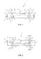
- FIG. 3is a sectional view of the hydraulic lifting apparatus shown in FIG. 2 , taken along line A-A;
- FIG. 4is a top view of one type of rectangular manhole cover with which a hydraulic lifting apparatus in accordance with one embodiment of the invention may be used;
- FIG. 5Ais a perspective view of a hydraulic lifting apparatus according the another embodiment of the invention.
- FIG. 5Bis a top view of the hydraulic lifting apparatus of FIG. 5A ;
- FIG. 5Dis an end view of the hydraulic lifting apparatus of FIG. 5A .
- FIGS. 1-5 of the drawingsin which like numbers designate like parts.
- Hydraulic lifting apparatus 1includes a lifting member 2 .
- Lifting member 2may be of any suitable construction.
- the lifting member 2has an elongated box-type structure, constructed of four steel plates fastened together in a suitable fashion, for example, by welding.
- lifting member 2could be constructed of a frame that includes tubular members.
- Lifting member 2preferably includes a plurality of lifting points 3 to which an appropriate rigging structure may be affixed in order to lift the complete hydraulic lifting apparatus 1 with rigging or lifting equipment, such as, a crane.
- rigging lines 4may be attached to lifting points 3 .
- Rigging lines 4may be constructed of steel wire, chain, or any other suitable material known in the art.
- Bearing plates 5may be fastened to lifting member 2 with bolts (as shown), by welding, or may be integral with the steel plates that form the lifting member 2 .
- rods 6are positioned through holes in the bearing plates 5 and corresponding holes of the steel plates that form the long sides of lifting member 2 . Appropriate means (not shown) to secure the rods 6 in the axial direction may be incorporated as is well known in the art.
- Rods 6may be of any suitable cross-sectional shape, such as, for example, round, square, or hexagonal.
- lifting hooks 7Affixed to the rods 6 in a suitable fashion, such as, for example, by welding, are a plurality of lifting hooks 7 that may extend in the downward direction (e.g., towards the ground).
- lifting hooks 7may removable from the rods 6 in a manner that permits disconnection and replacement with either a new lifting hook 7 of the same type, or a hook of a different type, depending upon the size of the rectangular manhole cover being lifted by the hydraulic lifting apparatus 1 or the particular location and structure of pockets 13 and lifting blocks 14 that are integral with the rectangular manhole cover, as shown, for example, on rectangular manhole cover 12 in FIG. 4 .
- Lifting hooks 7may be affixed to the ends of rods 6 , or may be affixed at a position offset from the ends, towards the center of rods 6 .
- the hydraulic lifting apparatus 1includes a hydraulic actuation device.
- Hydraulic actuation deviceincludes a hydraulic piston 9 with actuation members 10 and 11 .
- hydraulic actuation devicemay be operated by personnel from an appropriate distance by suitable connections and control equipment (not shown) as are known in the art.
- Activation of the hydraulic piston 9causes actuation members 10 and 11 to translate in a manner such that the ends of actuation members 10 and 11 , 10 a and 11 a , respectively, move towards one another.
- the ends 10 a and 11 a of actuation members 10 and 11are coupled to the top end of arms 8 , as shown.
- the coupling of ends 10 a and 11 a to arms 8may be disengaged, to allow for maintenance and/or replacement of hydraulic activation device, or any of its component parts.
- FIG. 4shows one type of rectangular manhole cover used to cover an access conduit that may be lifted and replaced using an embodiment of the hydraulic lifting apparatus 1 .
- Rectangular manhole cover 12includes an interface structure.
- the interface structure of rectangular manhole cover 12may include a plurality of pockets 13 . Integral with each pocket 13 is a lifting block 14 positioned such that lifting hook 7 may be inserted into the pocket 13 and under lifting block 14 to form an interface, or engagement, between the lifting hook 7 and the lifting block 14 and allow the rectangular manhole cover 12 to be lifted from the access conduit.
- hydraulic lifting apparatus 1is affixed to an appropriate rigging structure at lifting points 3 by rigging lines 4 .
- Rigging lines 4may be affixed to appropriate rigging or lifting equipment, such as a crane or similar device.
- the hydraulic lifting apparatus 1is moved into a position over the rectangular manhole cover 12 , and is lowered to allow lifting hooks 7 to be inserted into pockets 13 .
- the hydraulic piston 9is then activated by personnel from a remote location. As described above, activation of the hydraulic piston 9 causes ends 10 a and 11 a of actuation members 10 and 11 to move towards one another. Movement of ends 10 a and 11 a in this manner causes arms 8 , rods 6 , and lifting hooks 7 to rotate about the axis of rods 6 .
- the hydraulic lifting device 1 and rectangular manhole cover 12are appropriately positioned over the access conduit, again using suitable rigging equipment.
- the hydraulic lifting device 1 and rectangular manhole cover 12are then lowered such that rectangular manhole cover 12 is placed on top of the access conduit.
- Hydraulic piston 9may then be de-actuated by personnel from a remote location such that ends 10 a and 11 a of actuation members 10 and 11 move away from one another.
- FIGS. 5A-5Dare respectively perspective, top, side and end views of a hydraulic rectangular manhole cover lifting apparatus 20 according to another embodiment of the invention.
- Lifting apparatus 20is particularly suited for lifting rectangular manhole covers such as rectangular manhole cover 12 shown in FIG. 4 , although it may be used in other applications, as well.
- Lifting apparatus 20includes a generally rectangular frame having longitudinal frame members 21 a - 21 b and lateral frame members 22 a - 22 b .
- Longitudinal frame members 21 a - 21 b and lateral frame members 22 a - 22 bare preferably made of metal, such as steel, and can be one of a number of possible constructions, including tubular, solid, or channel, among others.
- longitudinal frame members 21 a - 21 bare of a channel construction and lateral frame members 22 a - 22 b are of a tubular construction.
- a first pair of rectangular tubular members 23 a - 23 battach lateral frame member 22 b to longitudinal frame members 21 a - 21 b .
- each tubular support 23 a - 23 bincludes an outer sidewall attached to a corresponding end of lateral frame member 22 b , for example by welding or bolts.
- the inner sidewalls of rectangular tubular members 23 a - 23 bform a rectangular tube for receiving one end of a corresponding longitudinal frame member 21 a - 21 b .
- rectangular tubular members 23 a - 23 b and lateral frame member 22 bform an end assembly, which is preferably fixed relative to longitudinal frame members 21 a - 21 b during the lifting operations described below.
- the fixed end assemblycomprised of lateral frame member 22 b and rectangular tubular members 23 a - 23 b is selectively positioned along longitudinal frame members 21 a - 21 b and held in place by bolts or pins 24 that extend through apertures 25 in the vertical walls of longitudinal frame members 21 a - 21 b ( FIG. 5C ).
- the position of the fixed end assembly (lateral frame member 22 b and rectangular tubular members 23 a - 23 b ) along longitudinal frame members 21 a - 21 bmay change through the use of pins 24 and apertures 24 , depending, for example, on the spacing of the lifting blocks 14 and pockets 13 on the manhole cover to be lifted.
- a first set of hooks 26 a - 26 bextend downward from the bottom walls of rectangular tubular members 23 a - 23 b , respectively ( FIG. 5A ).
- hooks 26 a - 26 bare adapted to engage one pair of lifting blocks 14 on manhole cover 12 of FIG. 4 .
- a second pair of rectangular tubular members 27 a - 27 battach lateral frame member 22 a to longitudinal frame members 21 a - 21 b .
- the end assembly comprised of rectangular tubular members 27 a - 27 b and lateral frame member 22 ais allowed to move (i.e., slide) along a part of the length of longitudinal frame members 21 a - 21 b during lifting operations
- a second set of hooks 28 a - 28 bextend downward from the bottom walls of rectangular tubular members 27 a - 27 b , respectively ( FIG. 5D ).
- hooks 28 a - 28 bare adapted to engage a second pair of lifting blocks 14 on manhole cover 12 of FIG. 4 .
- a central lateral support member 29is supported between longitudinal frame members 21 a - 21 b by rectangular tubular members 30 a - 30 b .
- Central lateral support 29is positioned along longitudinal frame members 21 a - 21 b and held into place with pins 24 and apertures 25 .
- the position of central lateral support member 29 along longitudinal frame members 21 a - 21 bmay change through the use of pins 24 and apertures 24 , depending, for example, on the spacing of lifting blocks 14 and pockets 13 and the resulting required positioning of the movable end assembly of lateral frame member 22 a and rectangular tubular members 27 a - 27 b.
- the movable shaft of a horizontal hydraulic piston assembly 31attaches to central lateral support member 29 with assembly 32 .
- the end of the body of horizontal piston assembly 31is fastened to lateral frame member 22 a .
- Central lateral support member 29also supports a four-way hydraulic flow divider 33 and a control valve 34 , both of which are discussed below.
- Each wheel assemblyincludes a wheel 36 and a wheel support bracket 37 .
- Each wheel support bracket 37pivots vertically in conjunction with assemblies 37 on corresponding rectangular tubular member pairs 23 a - 23 b and 27 a - 27 b.
- the pivoting of wheel assemblies 35 a - 35 dis implemented with vertical hydraulic units 39 a and 39 b , which in turn vertically raises and lowers lifting apparatus 20 to allow lifting and moving manhole cover 14 .
- Each vertical hydraulic unit 39includes a support structure 40 extending from lateral frame members 22 a - 22 b and vertical hydraulic piston assemblies 41 a - 41 b extending at an angle downwardly from the top of support structure 40 ( FIG. 5C ).
- the bodies of vertical hydraulic piston assemblies 41 a - 41 bare attached to upper ends of the corresponding support structure 40 and the ends of the moving piston shafts are attached to a point on the corresponding wheel assembly support frame 37 .
- Handles(not shown) may be inserted into the tubular structure of one or both of support structures 40 to allow manual movement of lifting apparatus 20 .
- vertical hydraulic units 39 a - 39 bUse of vertical hydraulic units 39 a - 39 b is not required. In alternate embodiments, vertical movement hydraulic units 39 a - 39 b may be eliminated from lifting apparatus 20 in their entirety.
- Lifting rings 43 a - 43 d at the corners of lifting apparatus 20are provided for engaging a crane or the like as an alternative means of raising and lowering lifting apparatus 20 and any engaged manhole cover.
- conventional horizontal piston assembly 31includes two hydraulic ports, one for receiving fluid under pressure to extend the piston shaft and another for receiving fluid under pressure for retracting the piston shaft. Each of these ports is connected by a hose and couplings to a corresponding port on control valve 34 .
- Control valve 34also includes another of ports that exchange fluid through a pair of hoses with a conventional hydraulic pump or pressure unit.
- Each vertical hydraulic piston assembly 41also exchanges fluid under pressure with a conventional hydraulic pump or pressure unit through a pair of hoses.
- Each vertical hydraulic piston assembly 41includes two ports, one for extending the piston shaft and one for retracting the piston shaft. Two hoses are then provided between four-way hydraulic flow divider 33 and each of the four vertical hydraulic piston assemblies 41 to provide pressure for lifting and lowering lifting apparatus 20 .
- lifting apparatus 20is positioned such that hooks 26 a - 26 b and 28 a - 28 b are within pockets 13 of manhole cover 12 , and aligned, but not yet engaged, with lifting blocks 14 .
- wheel assemblieswheel assemblies 35 a - 35 d and vertical movement hydraulic units 39 a - 39 b
- lifting apparatusis rolled into place and wheel assemblies 35 a - 35 d rotated upward to lower hooks 26 a - 26 b and 28 a - 28 b into pockets 13 . If only hooks 43 a - 43 d are available or being used, then lifting apparatus 20 can be lowered into position with a crane.
- piston assembly 31expands the distance between fixed hooks 26 a - 26 b and movable hooks 28 a - 28 b until lifting apparatus 20 is securely engaged with manhole cover 20 .
- the operating personnelcan move to a safe distance from the manhole cover 14 being lifted. Hydraulic fluid under pressure is then remotely provided to hydraulic piston assemblies 41 a - 41 b causing wheel assemblies 35 a - 35 b to rotate downward and lift manhole cover 12 upward. Lifting apparatus 20 and engaged manhole cover 12 can be subsequently rolled away from the access conduit. Alternatively, lifting apparatus and engaged manhole cover 12 can be lifted using a crane and hooks 43 a - 43 b.
Landscapes
- Engineering & Computer Science (AREA)
- Structural Engineering (AREA)
- Life Sciences & Earth Sciences (AREA)
- Mechanical Engineering (AREA)
- Civil Engineering (AREA)
- Geology (AREA)
- Environmental & Geological Engineering (AREA)
- General Life Sciences & Earth Sciences (AREA)
- Mining & Mineral Resources (AREA)
- Paleontology (AREA)
- General Engineering & Computer Science (AREA)
- Architecture (AREA)
- Underground Structures, Protecting, Testing And Restoring Foundations (AREA)
Abstract
Description
Claims (17)
Priority Applications (2)
| Application Number | Priority Date | Filing Date | Title |
|---|---|---|---|
| US13/621,513US9290370B1 (en) | 2010-09-13 | 2012-09-17 | Hydraulic lifting apparatus |
| US14/245,174US9725289B2 (en) | 2010-09-13 | 2014-04-04 | Hydraulic lifting apparatus |
Applications Claiming Priority (2)
| Application Number | Priority Date | Filing Date | Title |
|---|---|---|---|
| US12/880,824US20120061632A1 (en) | 2010-09-13 | 2010-09-13 | Hydraulic Lifting Apparatus |
| US13/621,513US9290370B1 (en) | 2010-09-13 | 2012-09-17 | Hydraulic lifting apparatus |
Related Parent Applications (1)
| Application Number | Title | Priority Date | Filing Date |
|---|---|---|---|
| US12/880,824Continuation-In-PartUS20120061632A1 (en) | 2010-09-13 | 2010-09-13 | Hydraulic Lifting Apparatus |
Related Child Applications (1)
| Application Number | Title | Priority Date | Filing Date |
|---|---|---|---|
| US14/245,174Continuation-In-PartUS9725289B2 (en) | 2010-09-13 | 2014-04-04 | Hydraulic lifting apparatus |
Publications (1)
| Publication Number | Publication Date |
|---|---|
| US9290370B1true US9290370B1 (en) | 2016-03-22 |
Family
ID=55487293
Family Applications (1)
| Application Number | Title | Priority Date | Filing Date |
|---|---|---|---|
| US13/621,513Expired - Fee RelatedUS9290370B1 (en) | 2010-09-13 | 2012-09-17 | Hydraulic lifting apparatus |
Country Status (1)
| Country | Link |
|---|---|
| US (1) | US9290370B1 (en) |
Cited By (11)
| Publication number | Priority date | Publication date | Assignee | Title |
|---|---|---|---|---|
| CN108083083A (en)* | 2017-12-21 | 2018-05-29 | 重庆千乔机电有限公司 | The process equipment of hoisting machinery |
| CN108589791A (en)* | 2018-07-18 | 2018-09-28 | 彭渤 | A kind of installation equipment of municipal administration inspection well cover |
| US20190106857A1 (en)* | 2017-10-10 | 2019-04-11 | Canada Pipe Company ULC | Frame positioning device for positioning a frame over an inlet of a catch basin or manhole and method for positioning the same |
| US10480151B1 (en)* | 2018-04-27 | 2019-11-19 | Michael K. Crites | Manhole removal device for use with a manhole cutting and removing tool |
| CN112357858A (en)* | 2020-11-20 | 2021-02-12 | 广东电网有限责任公司 | Manhole cover opening device |
| JP2022094414A (en)* | 2020-12-15 | 2022-06-27 | 西部技術コンサルタント株式会社 | Utility tunnel lid opening / closing conveyor |
| US11518661B2 (en) | 2020-01-07 | 2022-12-06 | Bigham Easy Lift, LLC | Cover lift and move apparatus |
| US20230078245A1 (en)* | 2021-09-13 | 2023-03-16 | Fer-Pal Construction, Ltd. | Road plate moving system and method |
| US11999595B1 (en)* | 2020-04-08 | 2024-06-04 | JJB Solutions LLC | Load lifter assembly |
| US12319388B2 (en) | 2020-04-08 | 2025-06-03 | JJB Solutions LLC | Load lifter assembly |
| US12351993B2 (en) | 2021-09-13 | 2025-07-08 | Fer-Pal Construction, Ltd. | Road plate moving system and method |
Citations (52)
| Publication number | Priority date | Publication date | Assignee | Title |
|---|---|---|---|---|
| US1716188A (en) | 1927-06-10 | 1929-06-04 | Rekenthaler Anthony William | Battery carrier and lifter |
| US1822629A (en) | 1930-04-14 | 1931-09-08 | American Sheet & Tin Plate | Hoisting mechanism |
| US1957719A (en) | 1933-04-06 | 1934-05-08 | Rotary Steel Company | Lifting device |
| US2554433A (en) | 1945-07-19 | 1951-05-22 | Millard R Warren | Block handling machine |
| US2747535A (en) | 1953-01-16 | 1956-05-29 | Elmer P Curry | Pneumatic clamp |
| US2946618A (en) | 1958-08-07 | 1960-07-26 | United States Steel Corp | Grapple |
| US2951725A (en) | 1957-07-22 | 1960-09-06 | Worcester Automatic Machine Co | Material handling apparatus |
| US3035336A (en)* | 1960-06-29 | 1962-05-22 | Taylor Wilson Mfg Company | Plug screw-on apparatus for pipe testers |
| US3164406A (en) | 1960-09-07 | 1965-01-05 | Leonard D Barry | Automatic holding device |
| DE1228380B (en)* | 1962-04-02 | 1966-11-10 | Josef Pesch | Gripping device for picking up and automatically releasing stacking plates |
| US3627157A (en) | 1968-07-01 | 1971-12-14 | Post Office | Lifting devices |
| US3695667A (en) | 1970-06-16 | 1972-10-03 | Frederick George Ullrich | Lifting devices |
| US3695670A (en) | 1971-01-08 | 1972-10-03 | Export Leaf Tobacco Co | Hogshead splitter |
| US3797676A (en)* | 1971-05-19 | 1974-03-19 | W Mccarthy | Adjustable shear bed |
| US3861649A (en) | 1974-01-15 | 1975-01-21 | Robert L Mosley | Manhole cover lifting device |
| US3899205A (en) | 1973-08-13 | 1975-08-12 | Mi Jack Products Inc | Container retrieval system |
| GB1500632A (en)* | 1976-03-09 | 1978-02-08 | Croydon Mayor Aldermen & Burge | Lifting devices |
| US4136903A (en) | 1977-05-16 | 1979-01-30 | Roethler Kenneth W | Tire lifting apparatus |
| US4181290A (en) | 1978-12-15 | 1980-01-01 | Affolter Bill G | Manhole cover lifting device |
| US4252358A (en)* | 1979-08-08 | 1981-02-24 | Klebs James P | Horizontal grapple |
| US4256429A (en)* | 1979-05-09 | 1981-03-17 | D. W. Zimmerman Mfg., Inc. | Apparatus for handling signature bundles |
| GB2109766A (en)* | 1981-06-02 | 1983-06-08 | Self Level Covers Aktiengesell | Man-hole cover, inspection cover or grating lifting device |
| US4482182A (en) | 1983-02-02 | 1984-11-13 | Mortensen James W | Manhole lid lifter |
| US4488706A (en) | 1982-04-01 | 1984-12-18 | Kazuhiko Kono | Manhole cover lifting hook |
| US4826388A (en) | 1987-04-01 | 1989-05-02 | Golding Simon S | Manhole cover lifter |
| GB2219984A (en)* | 1988-06-21 | 1989-12-28 | Peter David Irish | A manhole cover lifter |
| US4928927A (en)* | 1987-12-21 | 1990-05-29 | Fredrick William R | Lifting mechanism for heavy street gratings |
| US4973094A (en)* | 1988-09-27 | 1990-11-27 | Marinestar Nautica Di Tana Guido & C. S.N.C. | Crane implement for hoisting and launching boats to and from a quay |
| US4991893A (en) | 1988-08-25 | 1991-02-12 | Saddle Vent, Inc. | Manhole cover lifting device |
| US5141386A (en) | 1990-09-28 | 1992-08-25 | Barwise Robert D | Load handling apparatus with separable load coupling |
| US5165661A (en) | 1992-02-28 | 1992-11-24 | Wright D Ronnie | Lifting tool |
| JPH06136775A (en) | 1992-10-23 | 1994-05-17 | Shinichi Tsubakimori | Manhole frame removing machine |
| US5338150A (en)* | 1990-10-22 | 1994-08-16 | Focke & Co. (Gmbh & Co.) | Apparatus for handling articles, such as cartons |
| US5403057A (en)* | 1992-04-02 | 1995-04-04 | Nippodenso Co., Ltd. | Object holding apparatus |
| US5429490A (en)* | 1993-06-15 | 1995-07-04 | Concrete Products Incorporated | Apparatus and method for manipulating prefabricated concrete products |
| US5458435A (en) | 1994-04-11 | 1995-10-17 | Kohno; Kazuhiko | Opening and closing apparatus for manhole cover |
| JPH11323984A (en) | 1998-05-11 | 1999-11-26 | Takashu:Kk | Opening and closing device for manhole cover |
| US5997064A (en)* | 1996-12-06 | 1999-12-07 | Tsubakimoto Chain Co. | Article gripping apparatus |
| US6019565A (en)* | 1996-11-12 | 2000-02-01 | Gesuale; Thomas | Container lifting and transport apparatus |
| US20010032972A1 (en) | 2000-04-18 | 2001-10-25 | Fillisetti John P. | Lifting device |
| US6439628B1 (en) | 2001-03-19 | 2002-08-27 | At&T Corp. | Manhole cover removal tool |
| US6595566B1 (en) | 2001-07-13 | 2003-07-22 | Michael J. Donnan | Manhole cover lifter |
| US6749392B1 (en) | 2001-02-22 | 2004-06-15 | Ben A. Adams | Quick connect/disconnect tank lifting brace and method of use |
| US20040135389A1 (en) | 2003-01-09 | 2004-07-15 | Helms Robert J. | Lifting device for manhole tops and manhole covers |
| US6964407B1 (en) | 2004-06-28 | 2005-11-15 | Butler Ted A | Manhole cover lifter |
| GB2415007A (en)* | 2004-06-12 | 2005-12-14 | Kobus Jacobus Hendrik Cilliers | Lifting device for manhole covers |
| US20060118653A1 (en)* | 2004-11-05 | 2006-06-08 | Raven Industries, Inc. | Ground contacting boom height control system |
| US7387463B2 (en) | 2004-12-28 | 2008-06-17 | Winn Jr Walter T | Manhole cover removal apparatus and method of use |
| US20080159810A1 (en) | 2006-12-29 | 2008-07-03 | Parker Myers | Manhole cover extractor |
| US7562923B2 (en)* | 2004-02-09 | 2009-07-21 | Mirae Corporation | Tray transferring apparatus with gripper mechanism |
| US8226140B1 (en)* | 2009-03-30 | 2012-07-24 | Honda Motor Co., Ltd. | Article holding assembly |
| US8444366B2 (en)* | 2010-12-16 | 2013-05-21 | Jerry Allen Cole | Forklift adapter |
- 2012
- 2012-09-17USUS13/621,513patent/US9290370B1/ennot_activeExpired - Fee Related
Patent Citations (52)
| Publication number | Priority date | Publication date | Assignee | Title |
|---|---|---|---|---|
| US1716188A (en) | 1927-06-10 | 1929-06-04 | Rekenthaler Anthony William | Battery carrier and lifter |
| US1822629A (en) | 1930-04-14 | 1931-09-08 | American Sheet & Tin Plate | Hoisting mechanism |
| US1957719A (en) | 1933-04-06 | 1934-05-08 | Rotary Steel Company | Lifting device |
| US2554433A (en) | 1945-07-19 | 1951-05-22 | Millard R Warren | Block handling machine |
| US2747535A (en) | 1953-01-16 | 1956-05-29 | Elmer P Curry | Pneumatic clamp |
| US2951725A (en) | 1957-07-22 | 1960-09-06 | Worcester Automatic Machine Co | Material handling apparatus |
| US2946618A (en) | 1958-08-07 | 1960-07-26 | United States Steel Corp | Grapple |
| US3035336A (en)* | 1960-06-29 | 1962-05-22 | Taylor Wilson Mfg Company | Plug screw-on apparatus for pipe testers |
| US3164406A (en) | 1960-09-07 | 1965-01-05 | Leonard D Barry | Automatic holding device |
| DE1228380B (en)* | 1962-04-02 | 1966-11-10 | Josef Pesch | Gripping device for picking up and automatically releasing stacking plates |
| US3627157A (en) | 1968-07-01 | 1971-12-14 | Post Office | Lifting devices |
| US3695667A (en) | 1970-06-16 | 1972-10-03 | Frederick George Ullrich | Lifting devices |
| US3695670A (en) | 1971-01-08 | 1972-10-03 | Export Leaf Tobacco Co | Hogshead splitter |
| US3797676A (en)* | 1971-05-19 | 1974-03-19 | W Mccarthy | Adjustable shear bed |
| US3899205A (en) | 1973-08-13 | 1975-08-12 | Mi Jack Products Inc | Container retrieval system |
| US3861649A (en) | 1974-01-15 | 1975-01-21 | Robert L Mosley | Manhole cover lifting device |
| GB1500632A (en)* | 1976-03-09 | 1978-02-08 | Croydon Mayor Aldermen & Burge | Lifting devices |
| US4136903A (en) | 1977-05-16 | 1979-01-30 | Roethler Kenneth W | Tire lifting apparatus |
| US4181290A (en) | 1978-12-15 | 1980-01-01 | Affolter Bill G | Manhole cover lifting device |
| US4256429A (en)* | 1979-05-09 | 1981-03-17 | D. W. Zimmerman Mfg., Inc. | Apparatus for handling signature bundles |
| US4252358A (en)* | 1979-08-08 | 1981-02-24 | Klebs James P | Horizontal grapple |
| GB2109766A (en)* | 1981-06-02 | 1983-06-08 | Self Level Covers Aktiengesell | Man-hole cover, inspection cover or grating lifting device |
| US4488706A (en) | 1982-04-01 | 1984-12-18 | Kazuhiko Kono | Manhole cover lifting hook |
| US4482182A (en) | 1983-02-02 | 1984-11-13 | Mortensen James W | Manhole lid lifter |
| US4826388A (en) | 1987-04-01 | 1989-05-02 | Golding Simon S | Manhole cover lifter |
| US4928927A (en)* | 1987-12-21 | 1990-05-29 | Fredrick William R | Lifting mechanism for heavy street gratings |
| GB2219984A (en)* | 1988-06-21 | 1989-12-28 | Peter David Irish | A manhole cover lifter |
| US4991893A (en) | 1988-08-25 | 1991-02-12 | Saddle Vent, Inc. | Manhole cover lifting device |
| US4973094A (en)* | 1988-09-27 | 1990-11-27 | Marinestar Nautica Di Tana Guido & C. S.N.C. | Crane implement for hoisting and launching boats to and from a quay |
| US5141386A (en) | 1990-09-28 | 1992-08-25 | Barwise Robert D | Load handling apparatus with separable load coupling |
| US5338150A (en)* | 1990-10-22 | 1994-08-16 | Focke & Co. (Gmbh & Co.) | Apparatus for handling articles, such as cartons |
| US5165661A (en) | 1992-02-28 | 1992-11-24 | Wright D Ronnie | Lifting tool |
| US5403057A (en)* | 1992-04-02 | 1995-04-04 | Nippodenso Co., Ltd. | Object holding apparatus |
| JPH06136775A (en) | 1992-10-23 | 1994-05-17 | Shinichi Tsubakimori | Manhole frame removing machine |
| US5429490A (en)* | 1993-06-15 | 1995-07-04 | Concrete Products Incorporated | Apparatus and method for manipulating prefabricated concrete products |
| US5458435A (en) | 1994-04-11 | 1995-10-17 | Kohno; Kazuhiko | Opening and closing apparatus for manhole cover |
| US6019565A (en)* | 1996-11-12 | 2000-02-01 | Gesuale; Thomas | Container lifting and transport apparatus |
| US5997064A (en)* | 1996-12-06 | 1999-12-07 | Tsubakimoto Chain Co. | Article gripping apparatus |
| JPH11323984A (en) | 1998-05-11 | 1999-11-26 | Takashu:Kk | Opening and closing device for manhole cover |
| US20010032972A1 (en) | 2000-04-18 | 2001-10-25 | Fillisetti John P. | Lifting device |
| US6749392B1 (en) | 2001-02-22 | 2004-06-15 | Ben A. Adams | Quick connect/disconnect tank lifting brace and method of use |
| US6439628B1 (en) | 2001-03-19 | 2002-08-27 | At&T Corp. | Manhole cover removal tool |
| US6595566B1 (en) | 2001-07-13 | 2003-07-22 | Michael J. Donnan | Manhole cover lifter |
| US20040135389A1 (en) | 2003-01-09 | 2004-07-15 | Helms Robert J. | Lifting device for manhole tops and manhole covers |
| US7562923B2 (en)* | 2004-02-09 | 2009-07-21 | Mirae Corporation | Tray transferring apparatus with gripper mechanism |
| GB2415007A (en)* | 2004-06-12 | 2005-12-14 | Kobus Jacobus Hendrik Cilliers | Lifting device for manhole covers |
| US6964407B1 (en) | 2004-06-28 | 2005-11-15 | Butler Ted A | Manhole cover lifter |
| US20060118653A1 (en)* | 2004-11-05 | 2006-06-08 | Raven Industries, Inc. | Ground contacting boom height control system |
| US7387463B2 (en) | 2004-12-28 | 2008-06-17 | Winn Jr Walter T | Manhole cover removal apparatus and method of use |
| US20080159810A1 (en) | 2006-12-29 | 2008-07-03 | Parker Myers | Manhole cover extractor |
| US8226140B1 (en)* | 2009-03-30 | 2012-07-24 | Honda Motor Co., Ltd. | Article holding assembly |
| US8444366B2 (en)* | 2010-12-16 | 2013-05-21 | Jerry Allen Cole | Forklift adapter |
Cited By (11)
| Publication number | Priority date | Publication date | Assignee | Title |
|---|---|---|---|---|
| US20190106857A1 (en)* | 2017-10-10 | 2019-04-11 | Canada Pipe Company ULC | Frame positioning device for positioning a frame over an inlet of a catch basin or manhole and method for positioning the same |
| CN108083083A (en)* | 2017-12-21 | 2018-05-29 | 重庆千乔机电有限公司 | The process equipment of hoisting machinery |
| US10480151B1 (en)* | 2018-04-27 | 2019-11-19 | Michael K. Crites | Manhole removal device for use with a manhole cutting and removing tool |
| CN108589791A (en)* | 2018-07-18 | 2018-09-28 | 彭渤 | A kind of installation equipment of municipal administration inspection well cover |
| US11518661B2 (en) | 2020-01-07 | 2022-12-06 | Bigham Easy Lift, LLC | Cover lift and move apparatus |
| US11999595B1 (en)* | 2020-04-08 | 2024-06-04 | JJB Solutions LLC | Load lifter assembly |
| US12319388B2 (en) | 2020-04-08 | 2025-06-03 | JJB Solutions LLC | Load lifter assembly |
| CN112357858A (en)* | 2020-11-20 | 2021-02-12 | 广东电网有限责任公司 | Manhole cover opening device |
| JP2022094414A (en)* | 2020-12-15 | 2022-06-27 | 西部技術コンサルタント株式会社 | Utility tunnel lid opening / closing conveyor |
| US20230078245A1 (en)* | 2021-09-13 | 2023-03-16 | Fer-Pal Construction, Ltd. | Road plate moving system and method |
| US12351993B2 (en) | 2021-09-13 | 2025-07-08 | Fer-Pal Construction, Ltd. | Road plate moving system and method |
Similar Documents
| Publication | Publication Date | Title |
|---|---|---|
| US9290370B1 (en) | Hydraulic lifting apparatus | |
| EP2428484A1 (en) | Hydraulic lifting apparatus | |
| US9725289B2 (en) | Hydraulic lifting apparatus | |
| CN102367152B (en) | For promoting the apparatus and method of the tower wall portion of wind turbine | |
| US7950709B1 (en) | Method and apparatus for gripping and installing pipe | |
| JP6881843B2 (en) | Flange lifting tool | |
| JP2008519270A (en) | Chromatography column | |
| CA2848441A1 (en) | Hoisting apparatus and method of use | |
| AU2019204104A1 (en) | Device for inserting/removing pivot pins | |
| US5042601A (en) | Triple tool with sliding spider bowl | |
| US10352106B1 (en) | Cradle for retention, transportation and rotation of blowout preventer | |
| AU2017333416B2 (en) | Pile guide comprising a base frame and a guide member | |
| EP2396473B1 (en) | Lifting device for lifting a curb stone | |
| WO2007051880A1 (en) | Nacelle lifting tool and method | |
| EP3197808B1 (en) | Reel drive assembly | |
| US4490088A (en) | Lifting tool | |
| CN116853890A (en) | A rope releasing device | |
| CN112811309B (en) | Cable cover plate jack | |
| CN114590727A (en) | Confined space suspended pipeline device and method | |
| CN217780649U (en) | Building pipeline erects lifting machine | |
| KR101744937B1 (en) | Lift apparatus for pipe connection | |
| AU784497B2 (en) | Lifting and/or removal device | |
| CN115030123B (en) | Lifting platform equipment and operation method thereof | |
| KR102479475B1 (en) | 4 foot manhole switch | |
| CN103967106A (en) | Movable flood control, storm drainage, firefighting and drainage and irrigation device |
Legal Events
| Date | Code | Title | Description |
|---|---|---|---|
| ZAAA | Notice of allowance and fees due | Free format text:ORIGINAL CODE: NOA | |
| ZAAB | Notice of allowance mailed | Free format text:ORIGINAL CODE: MN/=. | |
| FEPP | Fee payment procedure | Free format text:PAYOR NUMBER ASSIGNED (ORIGINAL EVENT CODE: ASPN); ENTITY STATUS OF PATENT OWNER: SMALL ENTITY | |
| AS | Assignment | Owner name:HLBP DESIGN CORP., NEW YORK Free format text:ASSIGNMENT OF ASSIGNORS INTEREST;ASSIGNORS:PANIO, MICHAEL T;BAYNON, JEFFREY;SIGNING DATES FROM 20160119 TO 20160120;REEL/FRAME:037536/0718 | |
| STCF | Information on status: patent grant | Free format text:PATENTED CASE | |
| FEPP | Fee payment procedure | Free format text:MAINTENANCE FEE REMINDER MAILED (ORIGINAL EVENT CODE: REM.); ENTITY STATUS OF PATENT OWNER: SMALL ENTITY | |
| FEPP | Fee payment procedure | Free format text:SURCHARGE FOR LATE PAYMENT, SMALL ENTITY (ORIGINAL EVENT CODE: M2554); ENTITY STATUS OF PATENT OWNER: SMALL ENTITY | |
| MAFP | Maintenance fee payment | Free format text:PAYMENT OF MAINTENANCE FEE, 4TH YR, SMALL ENTITY (ORIGINAL EVENT CODE: M2551); ENTITY STATUS OF PATENT OWNER: SMALL ENTITY Year of fee payment:4 | |
| FEPP | Fee payment procedure | Free format text:MAINTENANCE FEE REMINDER MAILED (ORIGINAL EVENT CODE: REM.); ENTITY STATUS OF PATENT OWNER: SMALL ENTITY | |
| LAPS | Lapse for failure to pay maintenance fees | Free format text:PATENT EXPIRED FOR FAILURE TO PAY MAINTENANCE FEES (ORIGINAL EVENT CODE: EXP.); ENTITY STATUS OF PATENT OWNER: SMALL ENTITY | |
| STCH | Information on status: patent discontinuation | Free format text:PATENT EXPIRED DUE TO NONPAYMENT OF MAINTENANCE FEES UNDER 37 CFR 1.362 | |
| FP | Lapsed due to failure to pay maintenance fee | Effective date:20240322 |