US9289312B2 - Spinal implants with stem cells - Google Patents
Spinal implants with stem cellsDownload PDFInfo
- Publication number
- US9289312B2 US9289312B2US13/546,430US201213546430AUS9289312B2US 9289312 B2US9289312 B2US 9289312B2US 201213546430 AUS201213546430 AUS 201213546430AUS 9289312 B2US9289312 B2US 9289312B2
- Authority
- US
- United States
- Prior art keywords
- implant
- spinal
- spinal implant
- body structure
- synthetic
- Prior art date
- Legal status (The legal status is an assumption and is not a legal conclusion. Google has not performed a legal analysis and makes no representation as to the accuracy of the status listed.)
- Active, expires
Links
Images


Classifications
- A—HUMAN NECESSITIES
- A61—MEDICAL OR VETERINARY SCIENCE; HYGIENE
- A61F—FILTERS IMPLANTABLE INTO BLOOD VESSELS; PROSTHESES; DEVICES PROVIDING PATENCY TO, OR PREVENTING COLLAPSING OF, TUBULAR STRUCTURES OF THE BODY, e.g. STENTS; ORTHOPAEDIC, NURSING OR CONTRACEPTIVE DEVICES; FOMENTATION; TREATMENT OR PROTECTION OF EYES OR EARS; BANDAGES, DRESSINGS OR ABSORBENT PADS; FIRST-AID KITS
- A61F2/00—Filters implantable into blood vessels; Prostheses, i.e. artificial substitutes or replacements for parts of the body; Appliances for connecting them with the body; Devices providing patency to, or preventing collapsing of, tubular structures of the body, e.g. stents
- A61F2/0095—Packages or dispensers for prostheses or other implants
- A—HUMAN NECESSITIES
- A61—MEDICAL OR VETERINARY SCIENCE; HYGIENE
- A61B—DIAGNOSIS; SURGERY; IDENTIFICATION
- A61B50/00—Containers, covers, furniture or holders specially adapted for surgical or diagnostic appliances or instruments, e.g. sterile covers
- A61B50/30—Containers specially adapted for packaging, protecting, dispensing, collecting or disposing of surgical or diagnostic appliances or instruments
- A—HUMAN NECESSITIES
- A61—MEDICAL OR VETERINARY SCIENCE; HYGIENE
- A61F—FILTERS IMPLANTABLE INTO BLOOD VESSELS; PROSTHESES; DEVICES PROVIDING PATENCY TO, OR PREVENTING COLLAPSING OF, TUBULAR STRUCTURES OF THE BODY, e.g. STENTS; ORTHOPAEDIC, NURSING OR CONTRACEPTIVE DEVICES; FOMENTATION; TREATMENT OR PROTECTION OF EYES OR EARS; BANDAGES, DRESSINGS OR ABSORBENT PADS; FIRST-AID KITS
- A61F2/00—Filters implantable into blood vessels; Prostheses, i.e. artificial substitutes or replacements for parts of the body; Appliances for connecting them with the body; Devices providing patency to, or preventing collapsing of, tubular structures of the body, e.g. stents
- A61F2/02—Prostheses implantable into the body
- A61F2/30—Joints
- A61F2/44—Joints for the spine, e.g. vertebrae, spinal discs
- A61F2/4455—Joints for the spine, e.g. vertebrae, spinal discs for the fusion of spinal bodies, e.g. intervertebral fusion of adjacent spinal bodies, e.g. fusion cages
- A61F2/447—Joints for the spine, e.g. vertebrae, spinal discs for the fusion of spinal bodies, e.g. intervertebral fusion of adjacent spinal bodies, e.g. fusion cages substantially parallelepipedal, e.g. having a rectangular or trapezoidal cross-section
- A—HUMAN NECESSITIES
- A61—MEDICAL OR VETERINARY SCIENCE; HYGIENE
- A61L—METHODS OR APPARATUS FOR STERILISING MATERIALS OR OBJECTS IN GENERAL; DISINFECTION, STERILISATION OR DEODORISATION OF AIR; CHEMICAL ASPECTS OF BANDAGES, DRESSINGS, ABSORBENT PADS OR SURGICAL ARTICLES; MATERIALS FOR BANDAGES, DRESSINGS, ABSORBENT PADS OR SURGICAL ARTICLES
- A61L27/00—Materials for grafts or prostheses or for coating grafts or prostheses
- A61L27/02—Inorganic materials
- A61L27/04—Metals or alloys
- A61L27/042—Iron or iron alloys
- A—HUMAN NECESSITIES
- A61—MEDICAL OR VETERINARY SCIENCE; HYGIENE
- A61L—METHODS OR APPARATUS FOR STERILISING MATERIALS OR OBJECTS IN GENERAL; DISINFECTION, STERILISATION OR DEODORISATION OF AIR; CHEMICAL ASPECTS OF BANDAGES, DRESSINGS, ABSORBENT PADS OR SURGICAL ARTICLES; MATERIALS FOR BANDAGES, DRESSINGS, ABSORBENT PADS OR SURGICAL ARTICLES
- A61L27/00—Materials for grafts or prostheses or for coating grafts or prostheses
- A61L27/02—Inorganic materials
- A61L27/04—Metals or alloys
- A61L27/06—Titanium or titanium alloys
- A—HUMAN NECESSITIES
- A61—MEDICAL OR VETERINARY SCIENCE; HYGIENE
- A61L—METHODS OR APPARATUS FOR STERILISING MATERIALS OR OBJECTS IN GENERAL; DISINFECTION, STERILISATION OR DEODORISATION OF AIR; CHEMICAL ASPECTS OF BANDAGES, DRESSINGS, ABSORBENT PADS OR SURGICAL ARTICLES; MATERIALS FOR BANDAGES, DRESSINGS, ABSORBENT PADS OR SURGICAL ARTICLES
- A61L27/00—Materials for grafts or prostheses or for coating grafts or prostheses
- A61L27/14—Macromolecular materials
- A61L27/18—Macromolecular materials obtained otherwise than by reactions only involving carbon-to-carbon unsaturated bonds
- A—HUMAN NECESSITIES
- A61—MEDICAL OR VETERINARY SCIENCE; HYGIENE
- A61L—METHODS OR APPARATUS FOR STERILISING MATERIALS OR OBJECTS IN GENERAL; DISINFECTION, STERILISATION OR DEODORISATION OF AIR; CHEMICAL ASPECTS OF BANDAGES, DRESSINGS, ABSORBENT PADS OR SURGICAL ARTICLES; MATERIALS FOR BANDAGES, DRESSINGS, ABSORBENT PADS OR SURGICAL ARTICLES
- A61L27/00—Materials for grafts or prostheses or for coating grafts or prostheses
- A61L27/36—Materials for grafts or prostheses or for coating grafts or prostheses containing ingredients of undetermined constitution or reaction products thereof, e.g. transplant tissue, natural bone, extracellular matrix
- A61L27/38—Materials for grafts or prostheses or for coating grafts or prostheses containing ingredients of undetermined constitution or reaction products thereof, e.g. transplant tissue, natural bone, extracellular matrix containing added animal cells
- A61L27/3804—Materials for grafts or prostheses or for coating grafts or prostheses containing ingredients of undetermined constitution or reaction products thereof, e.g. transplant tissue, natural bone, extracellular matrix containing added animal cells characterised by specific cells or progenitors thereof, e.g. fibroblasts, connective tissue cells, kidney cells
- A61L27/3834—Cells able to produce different cell types, e.g. hematopoietic stem cells, mesenchymal stem cells, marrow stromal cells, embryonic stem cells
- C—CHEMISTRY; METALLURGY
- C08—ORGANIC MACROMOLECULAR COMPOUNDS; THEIR PREPARATION OR CHEMICAL WORKING-UP; COMPOSITIONS BASED THEREON
- C08L—COMPOSITIONS OF MACROMOLECULAR COMPOUNDS
- C08L71/00—Compositions of polyethers obtained by reactions forming an ether link in the main chain; Compositions of derivatives of such polymers
- A—HUMAN NECESSITIES
- A61—MEDICAL OR VETERINARY SCIENCE; HYGIENE
- A61F—FILTERS IMPLANTABLE INTO BLOOD VESSELS; PROSTHESES; DEVICES PROVIDING PATENCY TO, OR PREVENTING COLLAPSING OF, TUBULAR STRUCTURES OF THE BODY, e.g. STENTS; ORTHOPAEDIC, NURSING OR CONTRACEPTIVE DEVICES; FOMENTATION; TREATMENT OR PROTECTION OF EYES OR EARS; BANDAGES, DRESSINGS OR ABSORBENT PADS; FIRST-AID KITS
- A61F2/00—Filters implantable into blood vessels; Prostheses, i.e. artificial substitutes or replacements for parts of the body; Appliances for connecting them with the body; Devices providing patency to, or preventing collapsing of, tubular structures of the body, e.g. stents
- A61F2/02—Prostheses implantable into the body
- A61F2/30—Joints
- A61F2/46—Special tools for implanting artificial joints
- A61F2/4684—Trial or dummy prostheses
- A—HUMAN NECESSITIES
- A61—MEDICAL OR VETERINARY SCIENCE; HYGIENE
- A61F—FILTERS IMPLANTABLE INTO BLOOD VESSELS; PROSTHESES; DEVICES PROVIDING PATENCY TO, OR PREVENTING COLLAPSING OF, TUBULAR STRUCTURES OF THE BODY, e.g. STENTS; ORTHOPAEDIC, NURSING OR CONTRACEPTIVE DEVICES; FOMENTATION; TREATMENT OR PROTECTION OF EYES OR EARS; BANDAGES, DRESSINGS OR ABSORBENT PADS; FIRST-AID KITS
- A61F2/00—Filters implantable into blood vessels; Prostheses, i.e. artificial substitutes or replacements for parts of the body; Appliances for connecting them with the body; Devices providing patency to, or preventing collapsing of, tubular structures of the body, e.g. stents
- A61F2/02—Prostheses implantable into the body
- A61F2/28—Bones
- A61F2002/2817—Bone stimulation by chemical reactions or by osteogenic or biological products for enhancing ossification, e.g. by bone morphogenetic or morphogenic proteins [BMP] or by transforming growth factors [TGF]
- A—HUMAN NECESSITIES
- A61—MEDICAL OR VETERINARY SCIENCE; HYGIENE
- A61F—FILTERS IMPLANTABLE INTO BLOOD VESSELS; PROSTHESES; DEVICES PROVIDING PATENCY TO, OR PREVENTING COLLAPSING OF, TUBULAR STRUCTURES OF THE BODY, e.g. STENTS; ORTHOPAEDIC, NURSING OR CONTRACEPTIVE DEVICES; FOMENTATION; TREATMENT OR PROTECTION OF EYES OR EARS; BANDAGES, DRESSINGS OR ABSORBENT PADS; FIRST-AID KITS
- A61F2/00—Filters implantable into blood vessels; Prostheses, i.e. artificial substitutes or replacements for parts of the body; Appliances for connecting them with the body; Devices providing patency to, or preventing collapsing of, tubular structures of the body, e.g. stents
- A61F2/02—Prostheses implantable into the body
- A61F2/28—Bones
- A61F2002/2835—Bone graft implants for filling a bony defect or an endoprosthesis cavity, e.g. by synthetic material or biological material
- A—HUMAN NECESSITIES
- A61—MEDICAL OR VETERINARY SCIENCE; HYGIENE
- A61F—FILTERS IMPLANTABLE INTO BLOOD VESSELS; PROSTHESES; DEVICES PROVIDING PATENCY TO, OR PREVENTING COLLAPSING OF, TUBULAR STRUCTURES OF THE BODY, e.g. STENTS; ORTHOPAEDIC, NURSING OR CONTRACEPTIVE DEVICES; FOMENTATION; TREATMENT OR PROTECTION OF EYES OR EARS; BANDAGES, DRESSINGS OR ABSORBENT PADS; FIRST-AID KITS
- A61F2/00—Filters implantable into blood vessels; Prostheses, i.e. artificial substitutes or replacements for parts of the body; Appliances for connecting them with the body; Devices providing patency to, or preventing collapsing of, tubular structures of the body, e.g. stents
- A61F2/02—Prostheses implantable into the body
- A61F2/30—Joints
- A61F2002/30001—Additional features of subject-matter classified in A61F2/28, A61F2/30 and subgroups thereof
- A61F2002/30003—Material related properties of the prosthesis or of a coating on the prosthesis
- A61F2002/3006—Properties of materials and coating materials
- A61F2002/30062—(bio)absorbable, biodegradable, bioerodable, (bio)resorbable, resorptive
- A—HUMAN NECESSITIES
- A61—MEDICAL OR VETERINARY SCIENCE; HYGIENE
- A61F—FILTERS IMPLANTABLE INTO BLOOD VESSELS; PROSTHESES; DEVICES PROVIDING PATENCY TO, OR PREVENTING COLLAPSING OF, TUBULAR STRUCTURES OF THE BODY, e.g. STENTS; ORTHOPAEDIC, NURSING OR CONTRACEPTIVE DEVICES; FOMENTATION; TREATMENT OR PROTECTION OF EYES OR EARS; BANDAGES, DRESSINGS OR ABSORBENT PADS; FIRST-AID KITS
- A61F2/00—Filters implantable into blood vessels; Prostheses, i.e. artificial substitutes or replacements for parts of the body; Appliances for connecting them with the body; Devices providing patency to, or preventing collapsing of, tubular structures of the body, e.g. stents
- A61F2/02—Prostheses implantable into the body
- A61F2/30—Joints
- A61F2002/30001—Additional features of subject-matter classified in A61F2/28, A61F2/30 and subgroups thereof
- A61F2002/30003—Material related properties of the prosthesis or of a coating on the prosthesis
- A61F2002/3006—Properties of materials and coating materials
- A61F2002/30065—Properties of materials and coating materials thermoplastic, i.e. softening or fusing when heated, and hardening and becoming rigid again when cooled
- A—HUMAN NECESSITIES
- A61—MEDICAL OR VETERINARY SCIENCE; HYGIENE
- A61F—FILTERS IMPLANTABLE INTO BLOOD VESSELS; PROSTHESES; DEVICES PROVIDING PATENCY TO, OR PREVENTING COLLAPSING OF, TUBULAR STRUCTURES OF THE BODY, e.g. STENTS; ORTHOPAEDIC, NURSING OR CONTRACEPTIVE DEVICES; FOMENTATION; TREATMENT OR PROTECTION OF EYES OR EARS; BANDAGES, DRESSINGS OR ABSORBENT PADS; FIRST-AID KITS
- A61F2/00—Filters implantable into blood vessels; Prostheses, i.e. artificial substitutes or replacements for parts of the body; Appliances for connecting them with the body; Devices providing patency to, or preventing collapsing of, tubular structures of the body, e.g. stents
- A61F2/02—Prostheses implantable into the body
- A61F2/30—Joints
- A61F2002/30001—Additional features of subject-matter classified in A61F2/28, A61F2/30 and subgroups thereof
- A61F2002/30108—Shapes
- A61F2002/30199—Three-dimensional shapes
- A61F2002/30261—Three-dimensional shapes parallelepipedal
- A—HUMAN NECESSITIES
- A61—MEDICAL OR VETERINARY SCIENCE; HYGIENE
- A61F—FILTERS IMPLANTABLE INTO BLOOD VESSELS; PROSTHESES; DEVICES PROVIDING PATENCY TO, OR PREVENTING COLLAPSING OF, TUBULAR STRUCTURES OF THE BODY, e.g. STENTS; ORTHOPAEDIC, NURSING OR CONTRACEPTIVE DEVICES; FOMENTATION; TREATMENT OR PROTECTION OF EYES OR EARS; BANDAGES, DRESSINGS OR ABSORBENT PADS; FIRST-AID KITS
- A61F2/00—Filters implantable into blood vessels; Prostheses, i.e. artificial substitutes or replacements for parts of the body; Appliances for connecting them with the body; Devices providing patency to, or preventing collapsing of, tubular structures of the body, e.g. stents
- A61F2/02—Prostheses implantable into the body
- A61F2/30—Joints
- A61F2002/30001—Additional features of subject-matter classified in A61F2/28, A61F2/30 and subgroups thereof
- A61F2002/30316—The prosthesis having different structural features at different locations within the same prosthesis; Connections between prosthetic parts; Special structural features of bone or joint prostheses not otherwise provided for
- A61F2002/30317—The prosthesis having different structural features at different locations within the same prosthesis
- A61F2002/30322—The prosthesis having different structural features at different locations within the same prosthesis differing in surface structures
- A—HUMAN NECESSITIES
- A61—MEDICAL OR VETERINARY SCIENCE; HYGIENE
- A61F—FILTERS IMPLANTABLE INTO BLOOD VESSELS; PROSTHESES; DEVICES PROVIDING PATENCY TO, OR PREVENTING COLLAPSING OF, TUBULAR STRUCTURES OF THE BODY, e.g. STENTS; ORTHOPAEDIC, NURSING OR CONTRACEPTIVE DEVICES; FOMENTATION; TREATMENT OR PROTECTION OF EYES OR EARS; BANDAGES, DRESSINGS OR ABSORBENT PADS; FIRST-AID KITS
- A61F2/00—Filters implantable into blood vessels; Prostheses, i.e. artificial substitutes or replacements for parts of the body; Appliances for connecting them with the body; Devices providing patency to, or preventing collapsing of, tubular structures of the body, e.g. stents
- A61F2/02—Prostheses implantable into the body
- A61F2/30—Joints
- A61F2002/30001—Additional features of subject-matter classified in A61F2/28, A61F2/30 and subgroups thereof
- A61F2002/30316—The prosthesis having different structural features at different locations within the same prosthesis; Connections between prosthetic parts; Special structural features of bone or joint prostheses not otherwise provided for
- A61F2002/30329—Connections or couplings between prosthetic parts, e.g. between modular parts; Connecting elements
- A61F2002/30476—Connections or couplings between prosthetic parts, e.g. between modular parts; Connecting elements locked by an additional locking mechanism
- A61F2002/30477—Connections or couplings between prosthetic parts, e.g. between modular parts; Connecting elements locked by an additional locking mechanism using sharp protrusions, e.g. spikes, for anchoring into connecting prosthetic part
- A—HUMAN NECESSITIES
- A61—MEDICAL OR VETERINARY SCIENCE; HYGIENE
- A61F—FILTERS IMPLANTABLE INTO BLOOD VESSELS; PROSTHESES; DEVICES PROVIDING PATENCY TO, OR PREVENTING COLLAPSING OF, TUBULAR STRUCTURES OF THE BODY, e.g. STENTS; ORTHOPAEDIC, NURSING OR CONTRACEPTIVE DEVICES; FOMENTATION; TREATMENT OR PROTECTION OF EYES OR EARS; BANDAGES, DRESSINGS OR ABSORBENT PADS; FIRST-AID KITS
- A61F2/00—Filters implantable into blood vessels; Prostheses, i.e. artificial substitutes or replacements for parts of the body; Appliances for connecting them with the body; Devices providing patency to, or preventing collapsing of, tubular structures of the body, e.g. stents
- A61F2/02—Prostheses implantable into the body
- A61F2/30—Joints
- A61F2002/30001—Additional features of subject-matter classified in A61F2/28, A61F2/30 and subgroups thereof
- A61F2002/30316—The prosthesis having different structural features at different locations within the same prosthesis; Connections between prosthetic parts; Special structural features of bone or joint prostheses not otherwise provided for
- A61F2002/30535—Special structural features of bone or joint prostheses not otherwise provided for
- A61F2002/30593—Special structural features of bone or joint prostheses not otherwise provided for hollow
- A—HUMAN NECESSITIES
- A61—MEDICAL OR VETERINARY SCIENCE; HYGIENE
- A61F—FILTERS IMPLANTABLE INTO BLOOD VESSELS; PROSTHESES; DEVICES PROVIDING PATENCY TO, OR PREVENTING COLLAPSING OF, TUBULAR STRUCTURES OF THE BODY, e.g. STENTS; ORTHOPAEDIC, NURSING OR CONTRACEPTIVE DEVICES; FOMENTATION; TREATMENT OR PROTECTION OF EYES OR EARS; BANDAGES, DRESSINGS OR ABSORBENT PADS; FIRST-AID KITS
- A61F2/00—Filters implantable into blood vessels; Prostheses, i.e. artificial substitutes or replacements for parts of the body; Appliances for connecting them with the body; Devices providing patency to, or preventing collapsing of, tubular structures of the body, e.g. stents
- A61F2/02—Prostheses implantable into the body
- A61F2/30—Joints
- A61F2002/30001—Additional features of subject-matter classified in A61F2/28, A61F2/30 and subgroups thereof
- A61F2002/30316—The prosthesis having different structural features at different locations within the same prosthesis; Connections between prosthetic parts; Special structural features of bone or joint prostheses not otherwise provided for
- A61F2002/30535—Special structural features of bone or joint prostheses not otherwise provided for
- A61F2002/30604—Special structural features of bone or joint prostheses not otherwise provided for modular
- A61F2002/30607—Kits of prosthetic parts to be assembled in various combinations for forming different prostheses
- A—HUMAN NECESSITIES
- A61—MEDICAL OR VETERINARY SCIENCE; HYGIENE
- A61F—FILTERS IMPLANTABLE INTO BLOOD VESSELS; PROSTHESES; DEVICES PROVIDING PATENCY TO, OR PREVENTING COLLAPSING OF, TUBULAR STRUCTURES OF THE BODY, e.g. STENTS; ORTHOPAEDIC, NURSING OR CONTRACEPTIVE DEVICES; FOMENTATION; TREATMENT OR PROTECTION OF EYES OR EARS; BANDAGES, DRESSINGS OR ABSORBENT PADS; FIRST-AID KITS
- A61F2/00—Filters implantable into blood vessels; Prostheses, i.e. artificial substitutes or replacements for parts of the body; Appliances for connecting them with the body; Devices providing patency to, or preventing collapsing of, tubular structures of the body, e.g. stents
- A61F2/02—Prostheses implantable into the body
- A61F2/30—Joints
- A61F2002/30001—Additional features of subject-matter classified in A61F2/28, A61F2/30 and subgroups thereof
- A61F2002/30316—The prosthesis having different structural features at different locations within the same prosthesis; Connections between prosthetic parts; Special structural features of bone or joint prostheses not otherwise provided for
- A61F2002/30535—Special structural features of bone or joint prostheses not otherwise provided for
- A61F2002/30604—Special structural features of bone or joint prostheses not otherwise provided for modular
- A61F2002/30609—Sets comprising both coated and non-coated endoprostheses
- A61F2002/30611—
- A61F2002/30612—
- A—HUMAN NECESSITIES
- A61—MEDICAL OR VETERINARY SCIENCE; HYGIENE
- A61F—FILTERS IMPLANTABLE INTO BLOOD VESSELS; PROSTHESES; DEVICES PROVIDING PATENCY TO, OR PREVENTING COLLAPSING OF, TUBULAR STRUCTURES OF THE BODY, e.g. STENTS; ORTHOPAEDIC, NURSING OR CONTRACEPTIVE DEVICES; FOMENTATION; TREATMENT OR PROTECTION OF EYES OR EARS; BANDAGES, DRESSINGS OR ABSORBENT PADS; FIRST-AID KITS
- A61F2/00—Filters implantable into blood vessels; Prostheses, i.e. artificial substitutes or replacements for parts of the body; Appliances for connecting them with the body; Devices providing patency to, or preventing collapsing of, tubular structures of the body, e.g. stents
- A61F2/02—Prostheses implantable into the body
- A61F2/30—Joints
- A61F2002/30001—Additional features of subject-matter classified in A61F2/28, A61F2/30 and subgroups thereof
- A61F2002/30316—The prosthesis having different structural features at different locations within the same prosthesis; Connections between prosthetic parts; Special structural features of bone or joint prostheses not otherwise provided for
- A61F2002/30535—Special structural features of bone or joint prostheses not otherwise provided for
- A61F2002/30604—Special structural features of bone or joint prostheses not otherwise provided for modular
- A61F2002/30616—Sets comprising a plurality of prosthetic parts of different sizes or orientations
- A—HUMAN NECESSITIES
- A61—MEDICAL OR VETERINARY SCIENCE; HYGIENE
- A61F—FILTERS IMPLANTABLE INTO BLOOD VESSELS; PROSTHESES; DEVICES PROVIDING PATENCY TO, OR PREVENTING COLLAPSING OF, TUBULAR STRUCTURES OF THE BODY, e.g. STENTS; ORTHOPAEDIC, NURSING OR CONTRACEPTIVE DEVICES; FOMENTATION; TREATMENT OR PROTECTION OF EYES OR EARS; BANDAGES, DRESSINGS OR ABSORBENT PADS; FIRST-AID KITS
- A61F2/00—Filters implantable into blood vessels; Prostheses, i.e. artificial substitutes or replacements for parts of the body; Appliances for connecting them with the body; Devices providing patency to, or preventing collapsing of, tubular structures of the body, e.g. stents
- A61F2/02—Prostheses implantable into the body
- A61F2/30—Joints
- A61F2002/30001—Additional features of subject-matter classified in A61F2/28, A61F2/30 and subgroups thereof
- A61F2002/30621—Features concerning the anatomical functioning or articulation of the prosthetic joint
- A61F2002/30622—Implant for fusing a joint or bone material
- A—HUMAN NECESSITIES
- A61—MEDICAL OR VETERINARY SCIENCE; HYGIENE
- A61F—FILTERS IMPLANTABLE INTO BLOOD VESSELS; PROSTHESES; DEVICES PROVIDING PATENCY TO, OR PREVENTING COLLAPSING OF, TUBULAR STRUCTURES OF THE BODY, e.g. STENTS; ORTHOPAEDIC, NURSING OR CONTRACEPTIVE DEVICES; FOMENTATION; TREATMENT OR PROTECTION OF EYES OR EARS; BANDAGES, DRESSINGS OR ABSORBENT PADS; FIRST-AID KITS
- A61F2/00—Filters implantable into blood vessels; Prostheses, i.e. artificial substitutes or replacements for parts of the body; Appliances for connecting them with the body; Devices providing patency to, or preventing collapsing of, tubular structures of the body, e.g. stents
- A61F2/02—Prostheses implantable into the body
- A61F2/30—Joints
- A61F2/30767—Special external or bone-contacting surface, e.g. coating for improving bone ingrowth
- A61F2/30771—Special external or bone-contacting surface, e.g. coating for improving bone ingrowth applied in original prostheses, e.g. holes or grooves
- A61F2002/30772—Apertures or holes, e.g. of circular cross section
- A61F2002/30774—Apertures or holes, e.g. of circular cross section internally-threaded
- A—HUMAN NECESSITIES
- A61—MEDICAL OR VETERINARY SCIENCE; HYGIENE
- A61F—FILTERS IMPLANTABLE INTO BLOOD VESSELS; PROSTHESES; DEVICES PROVIDING PATENCY TO, OR PREVENTING COLLAPSING OF, TUBULAR STRUCTURES OF THE BODY, e.g. STENTS; ORTHOPAEDIC, NURSING OR CONTRACEPTIVE DEVICES; FOMENTATION; TREATMENT OR PROTECTION OF EYES OR EARS; BANDAGES, DRESSINGS OR ABSORBENT PADS; FIRST-AID KITS
- A61F2/00—Filters implantable into blood vessels; Prostheses, i.e. artificial substitutes or replacements for parts of the body; Appliances for connecting them with the body; Devices providing patency to, or preventing collapsing of, tubular structures of the body, e.g. stents
- A61F2/02—Prostheses implantable into the body
- A61F2/30—Joints
- A61F2/30767—Special external or bone-contacting surface, e.g. coating for improving bone ingrowth
- A61F2/30771—Special external or bone-contacting surface, e.g. coating for improving bone ingrowth applied in original prostheses, e.g. holes or grooves
- A61F2002/30772—Apertures or holes, e.g. of circular cross section
- A61F2002/30784—Plurality of holes
- A—HUMAN NECESSITIES
- A61—MEDICAL OR VETERINARY SCIENCE; HYGIENE
- A61F—FILTERS IMPLANTABLE INTO BLOOD VESSELS; PROSTHESES; DEVICES PROVIDING PATENCY TO, OR PREVENTING COLLAPSING OF, TUBULAR STRUCTURES OF THE BODY, e.g. STENTS; ORTHOPAEDIC, NURSING OR CONTRACEPTIVE DEVICES; FOMENTATION; TREATMENT OR PROTECTION OF EYES OR EARS; BANDAGES, DRESSINGS OR ABSORBENT PADS; FIRST-AID KITS
- A61F2/00—Filters implantable into blood vessels; Prostheses, i.e. artificial substitutes or replacements for parts of the body; Appliances for connecting them with the body; Devices providing patency to, or preventing collapsing of, tubular structures of the body, e.g. stents
- A61F2/02—Prostheses implantable into the body
- A61F2/30—Joints
- A61F2/30767—Special external or bone-contacting surface, e.g. coating for improving bone ingrowth
- A61F2/30771—Special external or bone-contacting surface, e.g. coating for improving bone ingrowth applied in original prostheses, e.g. holes or grooves
- A61F2002/30836—Special external or bone-contacting surface, e.g. coating for improving bone ingrowth applied in original prostheses, e.g. holes or grooves knurled
- A—HUMAN NECESSITIES
- A61—MEDICAL OR VETERINARY SCIENCE; HYGIENE
- A61F—FILTERS IMPLANTABLE INTO BLOOD VESSELS; PROSTHESES; DEVICES PROVIDING PATENCY TO, OR PREVENTING COLLAPSING OF, TUBULAR STRUCTURES OF THE BODY, e.g. STENTS; ORTHOPAEDIC, NURSING OR CONTRACEPTIVE DEVICES; FOMENTATION; TREATMENT OR PROTECTION OF EYES OR EARS; BANDAGES, DRESSINGS OR ABSORBENT PADS; FIRST-AID KITS
- A61F2/00—Filters implantable into blood vessels; Prostheses, i.e. artificial substitutes or replacements for parts of the body; Appliances for connecting them with the body; Devices providing patency to, or preventing collapsing of, tubular structures of the body, e.g. stents
- A61F2/02—Prostheses implantable into the body
- A61F2/30—Joints
- A61F2/30767—Special external or bone-contacting surface, e.g. coating for improving bone ingrowth
- A61F2/30771—Special external or bone-contacting surface, e.g. coating for improving bone ingrowth applied in original prostheses, e.g. holes or grooves
- A61F2002/30841—Sharp anchoring protrusions for impaction into the bone, e.g. sharp pins, spikes
- A61F2002/30843—Pyramidally-shaped
- A—HUMAN NECESSITIES
- A61—MEDICAL OR VETERINARY SCIENCE; HYGIENE
- A61F—FILTERS IMPLANTABLE INTO BLOOD VESSELS; PROSTHESES; DEVICES PROVIDING PATENCY TO, OR PREVENTING COLLAPSING OF, TUBULAR STRUCTURES OF THE BODY, e.g. STENTS; ORTHOPAEDIC, NURSING OR CONTRACEPTIVE DEVICES; FOMENTATION; TREATMENT OR PROTECTION OF EYES OR EARS; BANDAGES, DRESSINGS OR ABSORBENT PADS; FIRST-AID KITS
- A61F2/00—Filters implantable into blood vessels; Prostheses, i.e. artificial substitutes or replacements for parts of the body; Appliances for connecting them with the body; Devices providing patency to, or preventing collapsing of, tubular structures of the body, e.g. stents
- A61F2/02—Prostheses implantable into the body
- A61F2/30—Joints
- A61F2/30767—Special external or bone-contacting surface, e.g. coating for improving bone ingrowth
- A61F2/30771—Special external or bone-contacting surface, e.g. coating for improving bone ingrowth applied in original prostheses, e.g. holes or grooves
- A61F2002/30904—Special external or bone-contacting surface, e.g. coating for improving bone ingrowth applied in original prostheses, e.g. holes or grooves serrated profile, i.e. saw-toothed
- A—HUMAN NECESSITIES
- A61—MEDICAL OR VETERINARY SCIENCE; HYGIENE
- A61F—FILTERS IMPLANTABLE INTO BLOOD VESSELS; PROSTHESES; DEVICES PROVIDING PATENCY TO, OR PREVENTING COLLAPSING OF, TUBULAR STRUCTURES OF THE BODY, e.g. STENTS; ORTHOPAEDIC, NURSING OR CONTRACEPTIVE DEVICES; FOMENTATION; TREATMENT OR PROTECTION OF EYES OR EARS; BANDAGES, DRESSINGS OR ABSORBENT PADS; FIRST-AID KITS
- A61F2/00—Filters implantable into blood vessels; Prostheses, i.e. artificial substitutes or replacements for parts of the body; Appliances for connecting them with the body; Devices providing patency to, or preventing collapsing of, tubular structures of the body, e.g. stents
- A61F2/02—Prostheses implantable into the body
- A61F2/30—Joints
- A61F2/30767—Special external or bone-contacting surface, e.g. coating for improving bone ingrowth
- A61F2/30907—Nets or sleeves applied to surface of prostheses or in cement
- A61F2002/30909—Nets
- A61F2002/30912—Nets made of expanded metal, e.g. diamond mesh or metal nets having lozenge-shaped apertures
- A—HUMAN NECESSITIES
- A61—MEDICAL OR VETERINARY SCIENCE; HYGIENE
- A61F—FILTERS IMPLANTABLE INTO BLOOD VESSELS; PROSTHESES; DEVICES PROVIDING PATENCY TO, OR PREVENTING COLLAPSING OF, TUBULAR STRUCTURES OF THE BODY, e.g. STENTS; ORTHOPAEDIC, NURSING OR CONTRACEPTIVE DEVICES; FOMENTATION; TREATMENT OR PROTECTION OF EYES OR EARS; BANDAGES, DRESSINGS OR ABSORBENT PADS; FIRST-AID KITS
- A61F2/00—Filters implantable into blood vessels; Prostheses, i.e. artificial substitutes or replacements for parts of the body; Appliances for connecting them with the body; Devices providing patency to, or preventing collapsing of, tubular structures of the body, e.g. stents
- A61F2/02—Prostheses implantable into the body
- A61F2/30—Joints
- A61F2/30767—Special external or bone-contacting surface, e.g. coating for improving bone ingrowth
- A61F2/30907—Nets or sleeves applied to surface of prostheses or in cement
- A61F2002/30909—Nets
- A61F2002/30914—Details of the mesh structure, e.g. disposition of the woven warp and weft wires
- A—HUMAN NECESSITIES
- A61—MEDICAL OR VETERINARY SCIENCE; HYGIENE
- A61F—FILTERS IMPLANTABLE INTO BLOOD VESSELS; PROSTHESES; DEVICES PROVIDING PATENCY TO, OR PREVENTING COLLAPSING OF, TUBULAR STRUCTURES OF THE BODY, e.g. STENTS; ORTHOPAEDIC, NURSING OR CONTRACEPTIVE DEVICES; FOMENTATION; TREATMENT OR PROTECTION OF EYES OR EARS; BANDAGES, DRESSINGS OR ABSORBENT PADS; FIRST-AID KITS
- A61F2/00—Filters implantable into blood vessels; Prostheses, i.e. artificial substitutes or replacements for parts of the body; Appliances for connecting them with the body; Devices providing patency to, or preventing collapsing of, tubular structures of the body, e.g. stents
- A61F2/02—Prostheses implantable into the body
- A61F2/30—Joints
- A61F2/30767—Special external or bone-contacting surface, e.g. coating for improving bone ingrowth
- A61F2/30907—Nets or sleeves applied to surface of prostheses or in cement
- A61F2002/30909—Nets
- A61F2002/30915—Nets made of a stack of bonded perforated sheets, grids or wire meshes
- A—HUMAN NECESSITIES
- A61—MEDICAL OR VETERINARY SCIENCE; HYGIENE
- A61F—FILTERS IMPLANTABLE INTO BLOOD VESSELS; PROSTHESES; DEVICES PROVIDING PATENCY TO, OR PREVENTING COLLAPSING OF, TUBULAR STRUCTURES OF THE BODY, e.g. STENTS; ORTHOPAEDIC, NURSING OR CONTRACEPTIVE DEVICES; FOMENTATION; TREATMENT OR PROTECTION OF EYES OR EARS; BANDAGES, DRESSINGS OR ABSORBENT PADS; FIRST-AID KITS
- A61F2/00—Filters implantable into blood vessels; Prostheses, i.e. artificial substitutes or replacements for parts of the body; Appliances for connecting them with the body; Devices providing patency to, or preventing collapsing of, tubular structures of the body, e.g. stents
- A61F2/02—Prostheses implantable into the body
- A61F2/30—Joints
- A61F2/3094—Designing or manufacturing processes
- A61F2002/30971—Laminates, i.e. layered products
- A61F2002/30973—Two joined adjacent layers having complementary interlocking protrusions and recesses
- A61F2002/4475—
- A—HUMAN NECESSITIES
- A61—MEDICAL OR VETERINARY SCIENCE; HYGIENE
- A61F—FILTERS IMPLANTABLE INTO BLOOD VESSELS; PROSTHESES; DEVICES PROVIDING PATENCY TO, OR PREVENTING COLLAPSING OF, TUBULAR STRUCTURES OF THE BODY, e.g. STENTS; ORTHOPAEDIC, NURSING OR CONTRACEPTIVE DEVICES; FOMENTATION; TREATMENT OR PROTECTION OF EYES OR EARS; BANDAGES, DRESSINGS OR ABSORBENT PADS; FIRST-AID KITS
- A61F2/00—Filters implantable into blood vessels; Prostheses, i.e. artificial substitutes or replacements for parts of the body; Appliances for connecting them with the body; Devices providing patency to, or preventing collapsing of, tubular structures of the body, e.g. stents
- A61F2/02—Prostheses implantable into the body
- A61F2/30—Joints
- A61F2/44—Joints for the spine, e.g. vertebrae, spinal discs
- A61F2002/4495—Joints for the spine, e.g. vertebrae, spinal discs having a fabric structure, e.g. made from wires or fibres
- A—HUMAN NECESSITIES
- A61—MEDICAL OR VETERINARY SCIENCE; HYGIENE
- A61F—FILTERS IMPLANTABLE INTO BLOOD VESSELS; PROSTHESES; DEVICES PROVIDING PATENCY TO, OR PREVENTING COLLAPSING OF, TUBULAR STRUCTURES OF THE BODY, e.g. STENTS; ORTHOPAEDIC, NURSING OR CONTRACEPTIVE DEVICES; FOMENTATION; TREATMENT OR PROTECTION OF EYES OR EARS; BANDAGES, DRESSINGS OR ABSORBENT PADS; FIRST-AID KITS
- A61F2310/00—Prostheses classified in A61F2/28 or A61F2/30 - A61F2/44 being constructed from or coated with a particular material
- A61F2310/00005—The prosthesis being constructed from a particular material
- A61F2310/00011—Metals or alloys
- A61F2310/00017—Iron- or Fe-based alloys, e.g. stainless steel
- A—HUMAN NECESSITIES
- A61—MEDICAL OR VETERINARY SCIENCE; HYGIENE
- A61F—FILTERS IMPLANTABLE INTO BLOOD VESSELS; PROSTHESES; DEVICES PROVIDING PATENCY TO, OR PREVENTING COLLAPSING OF, TUBULAR STRUCTURES OF THE BODY, e.g. STENTS; ORTHOPAEDIC, NURSING OR CONTRACEPTIVE DEVICES; FOMENTATION; TREATMENT OR PROTECTION OF EYES OR EARS; BANDAGES, DRESSINGS OR ABSORBENT PADS; FIRST-AID KITS
- A61F2310/00—Prostheses classified in A61F2/28 or A61F2/30 - A61F2/44 being constructed from or coated with a particular material
- A61F2310/00005—The prosthesis being constructed from a particular material
- A61F2310/00011—Metals or alloys
- A61F2310/00023—Titanium or titanium-based alloys, e.g. Ti-Ni alloys
- A—HUMAN NECESSITIES
- A61—MEDICAL OR VETERINARY SCIENCE; HYGIENE
- A61F—FILTERS IMPLANTABLE INTO BLOOD VESSELS; PROSTHESES; DEVICES PROVIDING PATENCY TO, OR PREVENTING COLLAPSING OF, TUBULAR STRUCTURES OF THE BODY, e.g. STENTS; ORTHOPAEDIC, NURSING OR CONTRACEPTIVE DEVICES; FOMENTATION; TREATMENT OR PROTECTION OF EYES OR EARS; BANDAGES, DRESSINGS OR ABSORBENT PADS; FIRST-AID KITS
- A61F2310/00—Prostheses classified in A61F2/28 or A61F2/30 - A61F2/44 being constructed from or coated with a particular material
- A61F2310/00389—The prosthesis being coated or covered with a particular material
- A61F2310/00976—Coating or prosthesis-covering structure made of proteins or of polypeptides, e.g. of bone morphogenic proteins BMP or of transforming growth factors TGF
- A—HUMAN NECESSITIES
- A61—MEDICAL OR VETERINARY SCIENCE; HYGIENE
- A61L—METHODS OR APPARATUS FOR STERILISING MATERIALS OR OBJECTS IN GENERAL; DISINFECTION, STERILISATION OR DEODORISATION OF AIR; CHEMICAL ASPECTS OF BANDAGES, DRESSINGS, ABSORBENT PADS OR SURGICAL ARTICLES; MATERIALS FOR BANDAGES, DRESSINGS, ABSORBENT PADS OR SURGICAL ARTICLES
- A61L2430/00—Materials or treatment for tissue regeneration
- A61L2430/38—Materials or treatment for tissue regeneration for reconstruction of the spine, vertebrae or intervertebral discs
Definitions
- the present inventionrelates to spinal implant devices generally. More specifically to synthetic or metal implants wrapped or coated with stem cells.
- stem cell therapieshave had beneficial healing effects in relation to wound healing.
- the woundwhether caused by trauma or as part of a surgical procedure, appears and has been proven to heal more rapidly with the beneficial use of sutures laden with stem cells.
- a patentwas granted and publicly released called Biomatrix for soft tissue regeneration using mesenchymal stem cells which was U.S. Pat. No. 6,174,333 B1. This work was in conjunction with Case Western University and Osiris Therapeutics Inc. and disclosed the manufacture of a mat sheet that was formed into a spiral roll with sutures extending from opposite roll ends to form an implant laden with stem cells.
- the implant for repair of a tissue defectused a plurality of physiologically compatible load-bearing sutures for securing under tension tissue adjacent to the defect to be repaired, the sutures for supporting a tissue reparative cell mass in the defect and a tissue reparative cell mass supported thereby.
- the sutureshad a central portion encapsulated in a cell containing matrix which is contracted under a tensile load by the cells thereof and formed into a mat sheet during the contraction. Spring metal wires hold the sutures in tension during the contraction.
- the matrixwas a collagen gel or other material which the cells contract, the cells comprising human mesenchymal stem cells.
- WO 2010054527the use of stem cells was taught to be beneficial in jaw bone prosthesis. These prostheses. These prostheses were implants made of human tissue taken from cadavers.
- the present inventionproposes a new and beneficial use of stem cell coatings or preferably stem cell wraps in pliable sheet form as disclosed and described below.
- a spinal implant devicehas a synthetic or metallic or a combination thereof of these materials in an implant body structure and stem cells in a coating, or a sheet, wrap or a membrane wrap applied to surfaces on the synthetic or metallic or both implant body structure or alternatively filled with a plug of stem cell laden material.
- the implant body structurepreferably has an aperture or channel.
- the body structurecan be made of an implantable grade synthetic plastic, which is a thermoplastic or thermoset material.
- the plastic materialcan be any implantable grade material such as PEEK (polyether ether ketone), polyethylene, ultra high molecular weight polyethylene, polyphenylsulfone, polysulfone, polythermide, acetal copolymer, polyester woven or solid or implantable grade lennite UHME-PE.
- the implant body structurecan be made of stainless steel or titanium or any other acceptable implantable metallic material.
- the spinal implant devicemay include anchoring holes to secure the device to the spinal skeletal structure with fasteners or alternatively can simply be held in place by and between adjacent vertebrae.
- the spinal implant devicemay be pre-packaged as a kit with the body structure and the coating, sheet or membrane wrap laden with stem cells in a separate container to be applied to the body structure during the surgical procedure.
- the surgical implant devicemay be sterilized and then coated or wrapped or filled with a plug molded in the channel of the implant device with the stem cell laden material and packaged together in a sterile package or container.
- the package or containermay be sterile dry filled which may require re-hydrating the coated or wrapped implant or alternatively the spinal implant with a stem cell laden coating or wrap could be sterile liquid filled in which case the implant device can be directly implanted.
- the devicepermits several methods for treating a patient in need of a spinal implant.
- One methodhas the steps of preparing the patient to receive a spinal implant by surgically exposing the area to receive the spinal implant, the spinal implant having a synthetic or metallic or both body structure, coating or wrapping the body structure of the spinal implant, the coating or wrapping being a material laden with stem cells, implanting the coated or wrapped spinal implant and may also include hydrating the stem cell laden coating or wrap before wrapping the implant.
- the pre-applied stem cell laden spinal implant devicesimplifies the method by simply preparing the patient and implanting the spinal implant device pre-coated or wrapped with a stem cell laden material. This simplified procedure can require hydrating the implant if packaged dry or may not even require that additional step.
- FIGS. 1 a - 1 kare a number of perspective views of exemplary synthetic, metallic or a combination thereof spinal implants that can be made according to the present invention.
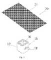
- FIG. 2is a depiction of a stem cell laden sheet or membrane material that can be used in the spinal implant made according to the present invention.
- FIG. 3is an exploded view of an exemplary pre-packaged kit with the spinal implant wrapped with a stem cell sheet or membrane according to the present invention.
- FIG. 4is an exploded view of an alternative embodiment pre-packaged kit with the spinal implant and a separate container with a stem cell laden coating in liquid or gel form.
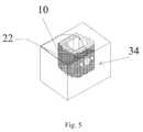
- FIG. 5is an exploded view of a sterile pre-packaged spinal implant with a coating applied.
- FIG. 6is an exploded view of a sterile spinal implant covered with a stem cell laden wrap.
- FIG. 7is an exploded view of a pre-packaged spinal implant made according to the present invention in a liquid filled sterile container.
- FIG. 8is a perspective view of the spinal implant shown being spray coated with a mist laden with stem cells.
- FIG. 9is a perspective view of an alternative embodiment of the present invention using droplets to apply the stem cells.
- FIG. 10is a perspective view of an alternative embodiment of the present invention showing the stem cells molded into a gelatinous plug.
- FIGS. 1 a - 1 ka number of perspective views of exemplary synthetic metallic or combinations thereof of spinal implants that are made according to the present invention are illustrated.
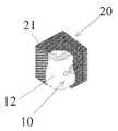
- Each of the implants 10 as shownhas a metallic, synthetic or combination of metallic and synthetic implant body structures 12 .
- the implant body structures 12 as shownare designed for insertion on or into a skeletal spinal structure of a patient.
- FIG. 1 ais the Phenix CID
- FIG. 1 bis the Talos-P PLIF
- FIG. 1 cis the TLIF
- FIG. 1 dis Talos-T TLIF
- FIG. 1 eis entitled OLIF
- FIG. 1 fis Talos-A ALIF
- FIG. 1 gis LLIF
- FIG. 1 his Thor Standalone ALIF
- FIG. 1 iis the Diamond Cervical Plate
- FIG. 1 jis the Facet Screw Skirt
- FIG. 1 kis a synthetic woven pouch used in bone grafting and repair.
- each of these exemplary spinal implant device examplesare manufactured and sold by Amendia or are competitor's alternatives that are also available for this purpose.
- each of these devicesare commonly referred to by reference numeral 10 for the device and 12 for its body structure even though they are structurally not the same in appearance each device 10 shown in FIGS. 1 a - 1 k is designed to function as a spinal implant device made in accordance to the present invention.
- the Phenix CID, PhenixTM—Cervical Interbody DeviceIs a rectangular implant comprised of PEEK-OPTIMA® polymer from Invibio Biomaterial Solutions, a radiolucent material with properties that match the modulus of elasticity of cortical bone.
- the PhenixTMis intended for use with supplemental spinal fixation systems that have been labeled for use in the cervical spine.
- the Phenix “PEEK-OPTIMA® polymer from Invibio Biomaterial Solutions Cervical Interbody Deviceis available in a range of sizes and heights to fit any anatomy and includes heights up to 12 mm. Available sizes range from a traditional 12 mm ⁇ 12 mm implant for small vertebral bodies to a 17 mm wide ⁇ 14 mm A/P implant that sits at the load bearing perimeter of the vertebral body and contains a large graft window.
- the Talos-P PLIFis a PEEK-OPTIMA lumbar interbody device for PLIF approach.
- This cageis available in 3 lengths, 2 widths and a complete range of heights with instrumentation that combines with the Talos®-T in one set to provide a complete Posterior and Transforaminal solution.
- the Talos-Tis a PEEK-OPTIMA lumbar interbody device for TLIF approach.
- the Talos-Tis a curved cage with a functional system for guiding the implant to a proper position.
- the instrumentation of the Talos®-Tis combined with the Talos®-P instrument set to provide a flexible solution for Posterior and Transforaminal approaches. It includes angled teeth prevent implant migration, tapered nose aids in insertion and distraction, angled shape improves fit between vertebral bodies, functional tamps guide implant to proper position and tantalum markers.
- the Talos-O OLIFthe Talos®-O is a truly unique percutaneous PEEK-OPTIMA lumbar interbody device that is delivered through an oblique approach.
- This interbodyis delivered through an annular incision that is anterior to the transverse process, and is totally percutaneous.
- the PEEK-OPTIMA implantdistracts and provides unquestioned rigid anterior support for the vertebral body.
- This oblique approachis achieved for all lumbar segments, including the L5-S1 disc space.
- Our discectomy instrumentswork through the small access portal to provide a complete percutaneous discectomy. Implants are available in lengths and heights to accommodate all varieties of lumbar interbody spaces.
- the Talos-A ALIFis a traditional ALIF interbody device that is available in a range of sizes to accommodate every anatomic requirement. Instrumentation is provided for delivery from an Anterior or Anterolateral approach. A variety of lordotic angles and sizes are available. It includes chamfered corners provide anatomical fit, angled teeth prevent implant migration, two insertion options for anterior or santerolateral approaches, lordotic angles to match spinal anatomy, implant trials and rasps for preparing disc space and tantalum markers.
- the Diamond Cervical Platethe Diamond Anterior Cervical Plate is a world class cervical plating system utilizing a unique self-locking mechanism that is effortless to engage and offers superior screw retention while providing a simple revision technique.
- the Diamond Cervical Plateis offered in single through four level varieties and has the option of fixed or variable screws, and self-tapping or self-drilling. Rescue screws are also provided.
- Benefitsinclude; superior back-out resistance, fixed and variable screws for rigid, dynamic, or hybrid stabilization, variable screws allow 30 degrees of freedom, low profile, easy to revise, color-coding of screws for length and fixed/variable head identification, instrumentation designed to reduce surgical steps, diamond window allows for greater graft visualization and self-drilling tip or conservative self-tapping tip.
- FIG. 1 kshows a surgical mesh made of a Polyethylene Terephthalate (PET) mesh pouch designed to contain impacted granular bone graft and enable its incorporation.
- PETPolyethylene Terephthalate
- the meshis used most commonly for traumatic fracture repair and interbody fusion.
- each of the body structures 12is provided with at least one vertically oriented channel 16 or aperture which extends through the implant device 10 .
- These channels 16are provided to enable bone tissue or bone graft material to be inserted into the device during a surgical procedure.
- Some of the exemplary embodimentshave a lateral or side opening or channel 18 .
- the side openings or channels 18are provided to enable an x-ray to pass through the implant device in order to establish bone formation in the patient after surgery has been completed and the implant has been inserted for a period of time.
- some implants 10may have holes 15 such as in the diamond cervical plate 10 of FIG.
- the exterior surface of the body structures 12 of each of these devicescan be coated with a coating 22 gel or spray of a biological substance or material containing stem cells 21 when made according to the present invention.
- a sheet or membrane 20 of materialcan be provided that is laden with stem cells 21 .
- This sheet or membrane 20can be wrapped around each of the exemplary implant devices 10 at the time of surgery if so desired.
- the sheet or membrane 20can form a wrap around the implant device 10 which can be pre-assembled at a manufacturing facility in a sterile environment, packaged and shipped to the medical facility for direct use as a surgical implant with a stem cell laden sheet or wrap membrane 20 material wrapped about the outer surface of the implant device 10 . It is this combination of the implant device 10 with a coating of stem cells 21 or a wrap 20 of stem cell material that provides an enhanced ability of the implant to be accepted by the patient in order for the implant to be fused by bone growth between vertebrae if so desired.
- the channels of the implant devices 10are filled with bone graft material either in a paste form or in solid bone material. This material during the patient's healing is expected to fuse with the adjacent vertebrae and by providing an envelope or covering of stem cells on the implant it is believed that the implant device 10 will be more quickly fused to the spinal skeletal structure in a faster more rapid fashion due to the ability of the stem cells to trigger the regenerative process and to allow the adjacent bone structure to grow around the implant device more quickly than would occur otherwise in the absence of the stem cell wrap 20 or coating 22 .
- the kitcan include the spinal implant device 10 with a separate stem cell laden wrap 20 included. These devices 10 and 20 when assembled as a kit can then be taken to an operating room and opened in an aseptic technique.
- the implant device 10preferably is prepackaged in a separate package as well as the stem cell laden wrap 20 being separately packaged in a package.
- FIG. 4an alternative embodiment is shown with a prepackaged kit wherein the spinal implant 10 can be separately packaged and a separate container 33 is provided filled with a stem cell laden coating 22 either in a liquid or gel form.
- this container 33can be provided with a sealed lid 35 in such a fashion that the implant device 10 can be dipped into the stem cell 21 laden coating material 22 or alternatively as shown in FIG. 8 can be provided in a spray device wherein the stem cells 21 can be sprayed directly onto the implant device 10 in a sterile and aseptic technique used in the operating room.
- a prepackaged kitcan be made where the spinal implant 10 is placed in a prepackaged container 34 with the coating 22 already applied.
- the spinal implant device 10can also be prepackaged and covered with the stem cell laden 20 wrap if so desired.
- this prepackaging of the stem cells 21requires that the spinal implant 10 be made in an aseptic or clean room environment in the absence of any secondary sterilization that might impede or kill the stem cells coated or otherwise wrapped onto the device.
- FIG. 7a view of the prepackaged spinal implant made according to the present invention is shown wherein the device 10 is stored in a clear liquid filled sterile container 34 .
- This liquid filled sterile container 34has a spinal implant device 10 either wrapped 20 or coated 22 but placed in a fluid or liquid that ensures that the stem cell 21 viability is maintained during shipping.
- the spinal implant 10must be made in a sterile or clean environment or sterilized prior to being placed in the container and prior to being coated or wrapped with the stem cell material in such a fashion that the stem cells are not damaged and remain viable so that when the surgeon implants the spinal device, the stem cells are active and capable of generating tissue regeneration in a rapid and fast healing manner.
- FIG. 8is a perspective view of a spinal implant device 10 shown being spray coated with a mist 22 laden with stem cells 21 from a spray nozzle container 42 prior to being inserted into a patient.
- This mist 22 laden with stem cells 21can be applied in the surgical room if so desired.
- FIG. 9the implant device of FIG. 1 k is shown being coated with stem cell 21 laden drops 22 from a liquid dropper 52 .
- the stem cells 21are molded into a gelatinous plug 24 that fills a hollow portion or channel 16 of the device of the implant 10 .
- the spinal implant 10has a body structure 12 made out of either a metallic material or a synthetic material. If made out of synthetic plastic material, it is preferred that the synthetic implantable grade plastic be either a thermoset or a thermoplastic material.
- suitable thermoplastic materialsare available for implanting such as polyether ether kethone, polyethylene, ultra high molecular weight polyethylene, polysulfone and any number of other materials.
- the implant body structure 12can be made out of a metallic material that is suitable for implanting. As shown, titanium or stainless steel materials are very suited for spinal implant devices.
- the implantable device 10 formed as a spinal implantis designed to either be anchored to the spinal structure or implanted by providing holes 15 or openings 15 through which threaded fasteners can be screwed directly into the bone structure if so desired.
- the implantable device 10can be unanchored and simply placed between vertebrae and held in place by and between adjacent vertebrae of the spinal skeletal structure. When held in this fashion, it is recommended that the upper surface 11 and lower exterior surface 13 have jagged or serrated teeth 17 configured to help hold the device 10 in place.
- the device 10When the device 10 is made with a body structure 12 having a fixation surface like the saw teeth 17 it is no problem for this structure to be wrapped with a stem cell laden sheet or skin-like membrane 20 or alternatively to be coated with a coating 22 of stem cells 21 at the surgical site.
- the stem cell 21being a wrap 20 of rather thin skin-like membrane simply will conform to the underlying teeth 17 or ridges, as shown in FIG. 6 , and therefore help assist and not impede the securing of the device 10 between the vertebrae.
- the spinal implant device 10 as presented according to the present inventionenables a variety of methods to be used for surgically treating a patient with a spinal defect which includes the steps of providing a spinal implant according to the present invention, preparing the patient to receive the spinal implant by surgically exposing the area to receive the spinal implant.
- the spinal implantpreferably being a synthetic or metallic body structure or a combination of those materials is coated or wrapped around the body structure of the spinal implant with a coating or wrapping laden with viable stem cells. Once the coating or wrapping is achieved, if done at the surgical site, the device 10 is implanted with the coated or wrapped spinal implant 10 is positioned into the spinal skeletal structure of the patient, the surgical wound is then sutured and the patient is sent into a recovery room.
- One additional stepis if the stem cell coating 22 or wrap 20 is in a dehydrated condition for shipping and storage, it may be necessary to hydrate the stem cells 21 with a liquid before wrapping or coating the implant 10 . If this is accomplished, the stem cell wrap or membrane 20 becomes far more pliable and easier to conform to the outer surface of the body structure 12 of the spinal implant 10 . If the spinal implant 10 is pretreated with a coating 22 or wrapping 20 laden with stem cells 21 , then the procedure is similar however the surgeon does not need to wrap the implant body structure because it will have been previously done at the manufacture site in such a case, the stem cells 21 if already hydrated can be placed directly into the patient. Alternatively, if they require hydrating this additional step of providing a liquid to the coating or wrap laden body structure will need to be accomplished in order to rehydrate the stem cells 21 within the coating 22 or wrap 20 .
- the spinal implant 10can be packaged in a variety of kits and provided to the surgeon either as separate components which are either wrapped or coated in the surgical suite or alternatively are pre-coated or wrapped at the manufacturing site, in either event, the present invention provides a unique and useful way of treating a spinal implant device with a material laden with viable stem cells in an attempt to accelerate bone regeneration and fusing of the implant 10 between vertebrae if so desired. While the present invention shows a variety of exemplary spinal implants 10 , it is understood that any number of spinal implants 10 having a synthetic or metallic or combination of materials can be coated or wrapped and these variations are considered in the scope of the present invention.
- the spinal implant body structure 12may include apertures 16 to provide additional biological material to facilitate in the fusing of the implant 10 to the skeletal bone structure, in such a case a paste of bone tissue may be provided within the aperture or channel 16 of the body structure 12 of the implant 10 .
- cadaver bonecould be used within the implant 10 , as such these are considered also within the scope of the present invention and they facilitate the fusing of the spinal implant 10 in combination with the use of a coating 22 or wrap 20 laden with stem cells 21 .
- any of the implant devices shown in FIGS. 1 a - 1 kcan be wrapped or coated or plugged with a stem cell laden material and the use of the exemplary implant device of FIG.
- FIGS. 1 a - 1 jwere not intended to be limiting, but rather exemplary of the present invention. It is believed significant that the implants illustrated in FIGS. 1 a - 1 j are made of a solid synthetic implantable plastic or metal or a combination of the two materials that is non-porous and inflexible.
- the implant of FIG. 1 kis a woven porous implantable device and as such is in a separate and otherwise distinct class from the others and while all are believed novel when combined with stem cells the group from FIGS. 1 a - 1 j are clearly unique spinal implant devices treated with a stem cell wrap, plug or coating that otherwise have no favorable porosity from which the stem cells can attach themselves.
Landscapes
- Health & Medical Sciences (AREA)
- Life Sciences & Earth Sciences (AREA)
- Engineering & Computer Science (AREA)
- Biomedical Technology (AREA)
- Chemical & Material Sciences (AREA)
- Veterinary Medicine (AREA)
- Public Health (AREA)
- Animal Behavior & Ethology (AREA)
- General Health & Medical Sciences (AREA)
- Transplantation (AREA)
- Oral & Maxillofacial Surgery (AREA)
- Orthopedic Medicine & Surgery (AREA)
- Neurology (AREA)
- Medicinal Chemistry (AREA)
- Dermatology (AREA)
- Epidemiology (AREA)
- Heart & Thoracic Surgery (AREA)
- Vascular Medicine (AREA)
- Cardiology (AREA)
- Chemical Kinetics & Catalysis (AREA)
- Inorganic Chemistry (AREA)
- Cell Biology (AREA)
- Surgery (AREA)
- Hematology (AREA)
- Urology & Nephrology (AREA)
- Zoology (AREA)
- Botany (AREA)
- Developmental Biology & Embryology (AREA)
- Nuclear Medicine, Radiotherapy & Molecular Imaging (AREA)
- Medical Informatics (AREA)
- Molecular Biology (AREA)
- Prostheses (AREA)
- Polymers & Plastics (AREA)
- Organic Chemistry (AREA)
Abstract
Description
Claims (20)
Priority Applications (6)
| Application Number | Priority Date | Filing Date | Title |
|---|---|---|---|
| US13/546,430US9289312B2 (en) | 2011-07-13 | 2012-07-11 | Spinal implants with stem cells |
| EP18203638.4AEP3461509A1 (en) | 2011-07-13 | 2012-07-11 | Spinal implants with stem cells |
| EP12811601.9AEP2731555B1 (en) | 2011-07-13 | 2012-07-11 | Spinal implants with stem cells |
| PCT/US2012/046209WO2013009837A1 (en) | 2011-07-13 | 2012-07-11 | Spinal implants with stem cells |
| US14/812,126US9814558B2 (en) | 2011-07-13 | 2015-07-29 | Spinal implants with stem cells |
| US15/045,724US9757223B2 (en) | 2011-07-13 | 2016-02-17 | Spinal implants with stem cells |
Applications Claiming Priority (2)
| Application Number | Priority Date | Filing Date | Title |
|---|---|---|---|
| US201161507310P | 2011-07-13 | 2011-07-13 | |
| US13/546,430US9289312B2 (en) | 2011-07-13 | 2012-07-11 | Spinal implants with stem cells |
Related Child Applications (2)
| Application Number | Title | Priority Date | Filing Date |
|---|---|---|---|
| US14/812,126DivisionUS9814558B2 (en) | 2011-07-13 | 2015-07-29 | Spinal implants with stem cells |
| US15/045,724DivisionUS9757223B2 (en) | 2011-07-13 | 2016-02-17 | Spinal implants with stem cells |
Publications (2)
| Publication Number | Publication Date |
|---|---|
| US20130018471A1 US20130018471A1 (en) | 2013-01-17 |
| US9289312B2true US9289312B2 (en) | 2016-03-22 |
Family
ID=47506484
Family Applications (3)
| Application Number | Title | Priority Date | Filing Date |
|---|---|---|---|
| US13/546,430Active2033-10-11US9289312B2 (en) | 2011-07-13 | 2012-07-11 | Spinal implants with stem cells |
| US14/812,126ActiveUS9814558B2 (en) | 2011-07-13 | 2015-07-29 | Spinal implants with stem cells |
| US15/045,724Active2032-08-25US9757223B2 (en) | 2011-07-13 | 2016-02-17 | Spinal implants with stem cells |
Family Applications After (2)
| Application Number | Title | Priority Date | Filing Date |
|---|---|---|---|
| US14/812,126ActiveUS9814558B2 (en) | 2011-07-13 | 2015-07-29 | Spinal implants with stem cells |
| US15/045,724Active2032-08-25US9757223B2 (en) | 2011-07-13 | 2016-02-17 | Spinal implants with stem cells |
Country Status (3)
| Country | Link |
|---|---|
| US (3) | US9289312B2 (en) |
| EP (2) | EP3461509A1 (en) |
| WO (1) | WO2013009837A1 (en) |
Cited By (15)
| Publication number | Priority date | Publication date | Assignee | Title |
|---|---|---|---|---|
| US9907654B2 (en)* | 2012-12-11 | 2018-03-06 | Dr. H.C. Robert Mathys Stiftung | Bone substitute and method for producing the same |
| USD847339S1 (en) | 2017-06-26 | 2019-04-30 | Advanced Research System, LLC | Spinal fusion cage |
| US10368930B2 (en)* | 2014-11-14 | 2019-08-06 | Warsaw Orthopedic,Inc. | Milled bone graft materials and methods of use |
| USD879295S1 (en) | 2017-02-13 | 2020-03-24 | Advance Research System, Llc | Spinal fusion cage |
| US11058551B2 (en) | 2016-12-16 | 2021-07-13 | Advance Research System, Llc | Interbody implant with concave profiled nose |
| US11737888B1 (en) | 2019-09-19 | 2023-08-29 | Advance Research System, Llc | Spinal fusion implant system and method |
| US11793652B2 (en) | 2017-11-21 | 2023-10-24 | Institute for Musculoskeletal Science and Education, Ltd. | Implant with improved bone contact |
| US11819419B2 (en) | 2015-04-29 | 2023-11-21 | Institute for Musculoskeletal Science and Education, Ltd. | Implant with curved bone contacting elements |
| US11826261B2 (en) | 2015-04-29 | 2023-11-28 | Institute for Musculoskeletal Science and Education, Ltd. | Coiled implants and systems and methods of use thereof |
| US11938039B2 (en) | 2017-03-13 | 2024-03-26 | Institute for Musculoskeletal Science and Education, Ltd. | Implant with structural members arranged around a ring |
| US11951018B2 (en) | 2017-11-21 | 2024-04-09 | Institute for Musculoskeletal Science and Education, Ltd. | Implant with improved flow characteristics |
| US12042399B2 (en) | 2016-10-25 | 2024-07-23 | Institute for Musculoskeletal Science and Education, Ltd. | Implant with protected fusion zones |
| US12097123B2 (en) | 2015-04-29 | 2024-09-24 | Institute for Musculoskeletal Science and Education, Ltd. | Implant with arched bone contacting elements |
| US12208011B2 (en) | 2016-10-25 | 2025-01-28 | Institute for Musculoskeletal Science and Education, Ltd. | Implant with multi-layer bone interfacing lattice |
| USD1095838S1 (en)* | 2021-10-15 | 2025-09-30 | Rv Medical Llc | Interbody device |
Families Citing this family (19)
| Publication number | Priority date | Publication date | Assignee | Title |
|---|---|---|---|---|
| US8287597B1 (en) | 2009-04-16 | 2012-10-16 | Nuvasive, Inc. | Method and apparatus for performing spine surgery |
| EP2547292B1 (en) | 2010-03-16 | 2019-04-24 | Pinnacle Spine Group, LLC | Ntervertebral implants and graft delivery systems |
| WO2012012327A1 (en)* | 2010-07-20 | 2012-01-26 | X-Spine Systems, Inc. | Composite orthopedic implant having a low friction material substrate with primary frictional features and secondary frictional features |
| US9380932B1 (en) | 2011-11-02 | 2016-07-05 | Pinnacle Spine Group, Llc | Retractor devices for minimally invasive access to the spine |
| US20130261746A1 (en)* | 2012-03-28 | 2013-10-03 | Linares Medical Devices, Llc | Implantable inter-vertebral disk having upper and lower layers of a metal exhibiting bone fusing characteristics and which sandwich therebetween a soft plastic cushioning disc for providing dynamic properties mimicking that of a natural inter-vertebral disc |
| US9693876B1 (en)* | 2012-03-30 | 2017-07-04 | Ali H. MESIWALA | Spinal fusion implant and related methods |
| WO2014159739A1 (en) | 2013-03-14 | 2014-10-02 | Pinnacle Spine Group, Llc | Interbody implants and graft delivery systems |
| US9486328B2 (en) | 2014-04-01 | 2016-11-08 | Ex Technology, Llc | Expandable intervertebral cage |
| US9763705B2 (en)* | 2014-10-03 | 2017-09-19 | Globus Medical, Inc. | Orthopedic stabilization devices and methods for installation thereof |
| WO2016137983A1 (en) | 2015-02-24 | 2016-09-01 | X-Spine Systems, Inc. | Modular interspinous fixation system with threaded component |
| CN106109064A (en)* | 2016-06-15 | 2016-11-16 | 东北大学 | A kind of spinal fusion device |
| IT201600124971A1 (en)* | 2016-12-12 | 2018-06-12 | Mt Ortho S R L | Intervertebral cage for bone fusion. |
| US10695157B2 (en) | 2017-01-10 | 2020-06-30 | Musculoskeletal Transplant Foundation | Packaging system for tissue grafts |
| US11375710B2 (en) | 2017-01-10 | 2022-07-05 | Musculoskeletal Transplant Foundation | Packaging system for tissue grafts |
| US10582994B2 (en) | 2018-03-06 | 2020-03-10 | Musculoskeletal Transplant Foundation | Implant packaging assembly |
| USD954993S1 (en) | 2020-06-17 | 2022-06-14 | Musculoskeletal Transplant Foundation | Tissue graft retainer |
| CN112155807A (en)* | 2020-10-30 | 2021-01-01 | 黄亚增 | Lumbar interbody fusion cage and use method thereof |
| WO2023055783A1 (en) | 2021-09-29 | 2023-04-06 | Ex Technology, Llc | Expandable intervertebral cage |
| US20230372077A1 (en)* | 2022-05-23 | 2023-11-23 | Kinamed, Inc. | Medical implants with nano surfaces |
Citations (43)
| Publication number | Priority date | Publication date | Assignee | Title |
|---|---|---|---|---|
| US6174333B1 (en) | 1994-06-06 | 2001-01-16 | Osiris Therapeutics, Inc. | Biomatrix for soft tissue regeneration using mesenchymal stem cells |
| US6254637B1 (en) | 2000-04-10 | 2001-07-03 | Lucid Korea Co., Ltd. | Artificial cornea and implantation thereof |
| US6261586B1 (en)* | 1997-06-11 | 2001-07-17 | Sdgi Holdings, Inc. | Bone graft composites and spacers |
| US6371988B1 (en)* | 1996-10-23 | 2002-04-16 | Sdgi Holdings, Inc. | Bone grafts |
| US20020143400A1 (en) | 1999-02-25 | 2002-10-03 | Depuy Acromed, Inc. | Spinal fusion implant |
| US6541024B1 (en)* | 1996-04-19 | 2003-04-01 | Osiris Therapeutics, Inc. | Regeneration and augmentation of bone using mesenchymal stem cells |
| US20030180263A1 (en)* | 2002-02-21 | 2003-09-25 | Peter Geistlich | Resorbable extracellular matrix for reconstruction of bone |
| WO2003083088A2 (en) | 2002-03-28 | 2003-10-09 | Ruggero Della Bitta | Stem cell therapy |
| US20040193270A1 (en)* | 2003-03-31 | 2004-09-30 | Depuyacromed, Inc. | Implantable bone graft |
| US20040193274A1 (en)* | 2003-03-28 | 2004-09-30 | Trieu Hai H. | Materials and methods for augmenting and/or repairing intervertebral discs |
| US20040259972A1 (en)* | 2003-06-20 | 2004-12-23 | Ringeisen Timothy A. | High density fibrous polymers suitable for implant |
| US20050070900A1 (en)* | 2003-09-30 | 2005-03-31 | Depuy Acromed, Inc. | Vertebral fusion device and method for using same |
| WO2005040361A1 (en) | 2003-10-28 | 2005-05-06 | Kyoto University | Method of simply preparing stem cell and feeder cell to be used therein |
| US20050154463A1 (en)* | 2000-08-30 | 2005-07-14 | Trieu Hal H. | Spinal nucleus replacement implants and methods |
| US20060159668A1 (en)* | 1997-10-10 | 2006-07-20 | Ed. Geistlich Soehne Ag Fuer Chemistrie Industrie | Resorbable extracellular matrix for reconstruction of bone |
| US20060276793A1 (en)* | 2005-05-26 | 2006-12-07 | Amedica Corporation | Bone fixation plate with self-locking screws |
| US20060276788A1 (en) | 2005-05-26 | 2006-12-07 | Amedica Corporation | Osteoconductive spinal fixation system |
| US20060293749A1 (en) | 2005-06-02 | 2006-12-28 | Zimmer Spine, Inc. | Interbody fusion ring and method of using the same |
| US20070100455A1 (en) | 2005-10-31 | 2007-05-03 | Depuy Spine, Inc. | Method and apparatus for fixation of intervertebral disc prosthesis |
| US20070141036A1 (en) | 2002-01-09 | 2007-06-21 | Alberto Gorrochategui Barrueta | Composition and procedure for tissue creation, regeneration and repair by a cell-bearing biological implant enriched with platelet concentrate and supplements |
| US20080097618A1 (en) | 2006-10-18 | 2008-04-24 | Kevin Charles Baker | Deposition of calcium-phosphate (CaP) and calcium-phosphate with bone morphogenic protein (CaP+BMP) coatings on metallic and polymeric surfaces |
| US20080119853A1 (en) | 2006-11-21 | 2008-05-22 | Jeffrey Felt | Methods and apparatus for minimally invasive modular interbody fusion devices |
| US20090105825A1 (en)* | 2007-10-19 | 2009-04-23 | Greg Foreman | Fusion methods using autologous stem cells |
| US20090175954A1 (en) | 2005-07-25 | 2009-07-09 | Arblast Co., Ltd. | Sheet-like composition |
| US20090198339A1 (en) | 2008-02-06 | 2009-08-06 | Nuvasive, Inc. | Systems and methods for spinal fusion |
| US20090209031A1 (en) | 2006-01-26 | 2009-08-20 | Tyco Healthcare Group Lp | Medical device package |
| US20090238855A1 (en) | 2007-05-10 | 2009-09-24 | Matheny Robert G | Laminate sheet articles for tissue regeneration |
| US20090254182A1 (en)* | 2008-04-02 | 2009-10-08 | John Kovarik | Intervertebral implant devices for supporting vertebrae and devices and methods for insertion thereof |
| CN101579537A (en) | 2009-07-07 | 2009-11-18 | 中国人民解放军第四军医大学 | Surface treatment method of tissue-engineered bioactive implant |
| US20090318962A1 (en) | 2008-06-24 | 2009-12-24 | Bioactive Surgical, Inc. | Surgical sutures incorporated with stem cells or other bioactive materials |
| US20100023129A1 (en) | 2008-07-22 | 2010-01-28 | Guo-Feng Xu | Jawbone prosthesis and method of manufacture |
| US20100034864A1 (en) | 2008-08-07 | 2010-02-11 | Bioactive Surgical, Inc. | Stem cell capture and immobilization coatings for medical devices and implants |
| US20100196437A1 (en) | 2004-05-27 | 2010-08-05 | Medtronic, Inc. | Medical devices having a surface including a biologically active agent therein |
| US20100203101A1 (en) | 2006-05-31 | 2010-08-12 | Biorigen S.R.L. | Bio-membrane for tissue regeneration |
| US7923246B2 (en) | 2004-05-27 | 2011-04-12 | Riken | Method of culturing embryonic stem cells with the use of amniotic membrane-origin factor |
| US20120010715A1 (en)* | 2008-12-26 | 2012-01-12 | Scott Spann | Method of retroperitoneal lateral insertion of spinal implants |
| US20120226319A1 (en)* | 2011-03-03 | 2012-09-06 | Warsaw Orthropedic, Inc. | Interbody device and plate for spinal stabilization and instruments for positioning same |
| US20120271361A1 (en)* | 2009-10-02 | 2012-10-25 | Drexel University | Functionalized Nanodiamond Reinforced Biopolymers |
| US20120277866A1 (en)* | 2011-04-28 | 2012-11-01 | Prakasam Kalluri | Angled Bullet-Nose Banana Cage |
| US8414654B1 (en)* | 2011-11-23 | 2013-04-09 | Amendia, Inc. | Bone implants and method of manufacture |
| US20130268075A1 (en)* | 2012-04-05 | 2013-10-10 | Warsaw Orthopedic, Inc. | Interbody bone implant device |
| US9011537B2 (en)* | 2009-02-12 | 2015-04-21 | Warsaw Orthopedic, Inc. | Delivery system cartridge |
| US9066993B2 (en)* | 2007-05-10 | 2015-06-30 | Cormatrix Cardiovascular, Inc. | Extracellular matrix encasement structures and methods |
Family Cites Families (7)
| Publication number | Priority date | Publication date | Assignee | Title |
|---|---|---|---|---|
| US6241769B1 (en)* | 1998-05-06 | 2001-06-05 | Cortek, Inc. | Implant for spinal fusion |
| US6989030B1 (en)* | 1999-11-11 | 2006-01-24 | Japan Tissue Engineering Co., Ltd. | Transplant material and method for fabricating the same |
| US7252685B2 (en)* | 2003-06-05 | 2007-08-07 | Sdgi Holdings, Inc. | Fusion implant and method of making same |
| US8080060B2 (en)* | 2007-05-30 | 2011-12-20 | Alphatec Spine, Inc. | Processes and systems for loading medical implants with simulative growth agents |
| WO2009131752A2 (en)* | 2008-04-25 | 2009-10-29 | Schapira Jay N | Programmed-release, nanostructured biological construct for stimulating cellular engraftment for tissue regeneration |
| US9034052B2 (en)* | 2013-01-14 | 2015-05-19 | Warsaw Orthopedic, Inc. | Delivery systems containing bioactive materials |
| US9283013B2 (en)* | 2013-03-14 | 2016-03-15 | Warsaw Orthopedic, Inc. | Filling systems for bone delivery devices |
- 2012
- 2012-07-11EPEP18203638.4Apatent/EP3461509A1/enactivePending
- 2012-07-11WOPCT/US2012/046209patent/WO2013009837A1/enactiveApplication Filing
- 2012-07-11EPEP12811601.9Apatent/EP2731555B1/enactiveActive
- 2012-07-11USUS13/546,430patent/US9289312B2/enactiveActive
- 2015
- 2015-07-29USUS14/812,126patent/US9814558B2/enactiveActive
- 2016
- 2016-02-17USUS15/045,724patent/US9757223B2/enactiveActive
Patent Citations (46)
| Publication number | Priority date | Publication date | Assignee | Title |
|---|---|---|---|---|
| US6174333B1 (en) | 1994-06-06 | 2001-01-16 | Osiris Therapeutics, Inc. | Biomatrix for soft tissue regeneration using mesenchymal stem cells |
| US6863900B2 (en) | 1996-04-19 | 2005-03-08 | Osiris Therapeutics, Inc. | Regeneration and augmentation of bone using mesenchymal stem cells |
| US6541024B1 (en)* | 1996-04-19 | 2003-04-01 | Osiris Therapeutics, Inc. | Regeneration and augmentation of bone using mesenchymal stem cells |
| US6371988B1 (en)* | 1996-10-23 | 2002-04-16 | Sdgi Holdings, Inc. | Bone grafts |
| US6261586B1 (en)* | 1997-06-11 | 2001-07-17 | Sdgi Holdings, Inc. | Bone graft composites and spacers |
| US20060159668A1 (en)* | 1997-10-10 | 2006-07-20 | Ed. Geistlich Soehne Ag Fuer Chemistrie Industrie | Resorbable extracellular matrix for reconstruction of bone |
| US20020143400A1 (en) | 1999-02-25 | 2002-10-03 | Depuy Acromed, Inc. | Spinal fusion implant |
| US6254637B1 (en) | 2000-04-10 | 2001-07-03 | Lucid Korea Co., Ltd. | Artificial cornea and implantation thereof |
| US20050154463A1 (en)* | 2000-08-30 | 2005-07-14 | Trieu Hal H. | Spinal nucleus replacement implants and methods |
| US20070141036A1 (en) | 2002-01-09 | 2007-06-21 | Alberto Gorrochategui Barrueta | Composition and procedure for tissue creation, regeneration and repair by a cell-bearing biological implant enriched with platelet concentrate and supplements |
| US20030180263A1 (en)* | 2002-02-21 | 2003-09-25 | Peter Geistlich | Resorbable extracellular matrix for reconstruction of bone |
| WO2003083088A2 (en) | 2002-03-28 | 2003-10-09 | Ruggero Della Bitta | Stem cell therapy |
| US20040193274A1 (en)* | 2003-03-28 | 2004-09-30 | Trieu Hai H. | Materials and methods for augmenting and/or repairing intervertebral discs |
| US20040193270A1 (en)* | 2003-03-31 | 2004-09-30 | Depuyacromed, Inc. | Implantable bone graft |
| US20040259972A1 (en)* | 2003-06-20 | 2004-12-23 | Ringeisen Timothy A. | High density fibrous polymers suitable for implant |
| US20050070900A1 (en)* | 2003-09-30 | 2005-03-31 | Depuy Acromed, Inc. | Vertebral fusion device and method for using same |
| WO2005040361A1 (en) | 2003-10-28 | 2005-05-06 | Kyoto University | Method of simply preparing stem cell and feeder cell to be used therein |
| US20100196437A1 (en) | 2004-05-27 | 2010-08-05 | Medtronic, Inc. | Medical devices having a surface including a biologically active agent therein |
| US7923246B2 (en) | 2004-05-27 | 2011-04-12 | Riken | Method of culturing embryonic stem cells with the use of amniotic membrane-origin factor |
| US20060276793A1 (en)* | 2005-05-26 | 2006-12-07 | Amedica Corporation | Bone fixation plate with self-locking screws |
| US20060276788A1 (en) | 2005-05-26 | 2006-12-07 | Amedica Corporation | Osteoconductive spinal fixation system |
| US20060293749A1 (en) | 2005-06-02 | 2006-12-28 | Zimmer Spine, Inc. | Interbody fusion ring and method of using the same |
| US20090175954A1 (en) | 2005-07-25 | 2009-07-09 | Arblast Co., Ltd. | Sheet-like composition |
| US20070100455A1 (en) | 2005-10-31 | 2007-05-03 | Depuy Spine, Inc. | Method and apparatus for fixation of intervertebral disc prosthesis |
| US20090209031A1 (en) | 2006-01-26 | 2009-08-20 | Tyco Healthcare Group Lp | Medical device package |
| US20100203101A1 (en) | 2006-05-31 | 2010-08-12 | Biorigen S.R.L. | Bio-membrane for tissue regeneration |
| US20080097618A1 (en) | 2006-10-18 | 2008-04-24 | Kevin Charles Baker | Deposition of calcium-phosphate (CaP) and calcium-phosphate with bone morphogenic protein (CaP+BMP) coatings on metallic and polymeric surfaces |
| US20080119853A1 (en) | 2006-11-21 | 2008-05-22 | Jeffrey Felt | Methods and apparatus for minimally invasive modular interbody fusion devices |
| US9066993B2 (en)* | 2007-05-10 | 2015-06-30 | Cormatrix Cardiovascular, Inc. | Extracellular matrix encasement structures and methods |
| US8758448B2 (en)* | 2007-05-10 | 2014-06-24 | Cormatrix Cardiovascular, Inc. | Laminate sheet articles for tissue regeneration |
| US20090238855A1 (en) | 2007-05-10 | 2009-09-24 | Matheny Robert G | Laminate sheet articles for tissue regeneration |
| US20090105825A1 (en)* | 2007-10-19 | 2009-04-23 | Greg Foreman | Fusion methods using autologous stem cells |
| US20090198339A1 (en) | 2008-02-06 | 2009-08-06 | Nuvasive, Inc. | Systems and methods for spinal fusion |
| US20090254182A1 (en)* | 2008-04-02 | 2009-10-08 | John Kovarik | Intervertebral implant devices for supporting vertebrae and devices and methods for insertion thereof |
| US20090318962A1 (en) | 2008-06-24 | 2009-12-24 | Bioactive Surgical, Inc. | Surgical sutures incorporated with stem cells or other bioactive materials |
| US20100023129A1 (en) | 2008-07-22 | 2010-01-28 | Guo-Feng Xu | Jawbone prosthesis and method of manufacture |
| US20100034864A1 (en) | 2008-08-07 | 2010-02-11 | Bioactive Surgical, Inc. | Stem cell capture and immobilization coatings for medical devices and implants |
| WO2010054527A1 (en) | 2008-11-13 | 2010-05-20 | Grandhope Biotech Co., Ltd. | Jawbone prosthesis and manufacturing method thereof |
| US20120010715A1 (en)* | 2008-12-26 | 2012-01-12 | Scott Spann | Method of retroperitoneal lateral insertion of spinal implants |
| US9011537B2 (en)* | 2009-02-12 | 2015-04-21 | Warsaw Orthopedic, Inc. | Delivery system cartridge |
| CN101579537A (en) | 2009-07-07 | 2009-11-18 | 中国人民解放军第四军医大学 | Surface treatment method of tissue-engineered bioactive implant |
| US20120271361A1 (en)* | 2009-10-02 | 2012-10-25 | Drexel University | Functionalized Nanodiamond Reinforced Biopolymers |
| US20120226319A1 (en)* | 2011-03-03 | 2012-09-06 | Warsaw Orthropedic, Inc. | Interbody device and plate for spinal stabilization and instruments for positioning same |
| US20120277866A1 (en)* | 2011-04-28 | 2012-11-01 | Prakasam Kalluri | Angled Bullet-Nose Banana Cage |
| US8414654B1 (en)* | 2011-11-23 | 2013-04-09 | Amendia, Inc. | Bone implants and method of manufacture |
| US20130268075A1 (en)* | 2012-04-05 | 2013-10-10 | Warsaw Orthopedic, Inc. | Interbody bone implant device |
Non-Patent Citations (1)
| Title |
|---|
| Bearingworks.com; PEEK Data Sheet; available as of Sep. 2010; accessed Sep. 15, 2015. http://www.bearingworks.com/content-files/pdf/retainers/PEEK%20datasheet.pdf. Relevant data at pp. 1 of 3.* |
Cited By (18)
| Publication number | Priority date | Publication date | Assignee | Title |
|---|---|---|---|---|
| US9907654B2 (en)* | 2012-12-11 | 2018-03-06 | Dr. H.C. Robert Mathys Stiftung | Bone substitute and method for producing the same |
| US10368930B2 (en)* | 2014-11-14 | 2019-08-06 | Warsaw Orthopedic,Inc. | Milled bone graft materials and methods of use |
| US11819419B2 (en) | 2015-04-29 | 2023-11-21 | Institute for Musculoskeletal Science and Education, Ltd. | Implant with curved bone contacting elements |
| US12097123B2 (en) | 2015-04-29 | 2024-09-24 | Institute for Musculoskeletal Science and Education, Ltd. | Implant with arched bone contacting elements |
| US11826261B2 (en) | 2015-04-29 | 2023-11-28 | Institute for Musculoskeletal Science and Education, Ltd. | Coiled implants and systems and methods of use thereof |
| US12042399B2 (en) | 2016-10-25 | 2024-07-23 | Institute for Musculoskeletal Science and Education, Ltd. | Implant with protected fusion zones |
| US12208011B2 (en) | 2016-10-25 | 2025-01-28 | Institute for Musculoskeletal Science and Education, Ltd. | Implant with multi-layer bone interfacing lattice |
| US11058551B2 (en) | 2016-12-16 | 2021-07-13 | Advance Research System, Llc | Interbody implant with concave profiled nose |
| USD923178S1 (en) | 2017-02-13 | 2021-06-22 | Advance Research System, Llc | Spinal fusion cage |
| USD879295S1 (en) | 2017-02-13 | 2020-03-24 | Advance Research System, Llc | Spinal fusion cage |
| US11938039B2 (en) | 2017-03-13 | 2024-03-26 | Institute for Musculoskeletal Science and Education, Ltd. | Implant with structural members arranged around a ring |
| US12303400B2 (en) | 2017-03-13 | 2025-05-20 | Institute for Musculoskeletal Science and Education, Ltd. | Implant with structural members arranged around a ring |
| USD847339S1 (en) | 2017-06-26 | 2019-04-30 | Advanced Research System, LLC | Spinal fusion cage |
| US11793652B2 (en) | 2017-11-21 | 2023-10-24 | Institute for Musculoskeletal Science and Education, Ltd. | Implant with improved bone contact |
| US11951018B2 (en) | 2017-11-21 | 2024-04-09 | Institute for Musculoskeletal Science and Education, Ltd. | Implant with improved flow characteristics |
| US12186200B2 (en) | 2017-11-21 | 2025-01-07 | Institute for Musculoskeletal Science and Education, Ltd. | Implant with improved bone contact |
| US11737888B1 (en) | 2019-09-19 | 2023-08-29 | Advance Research System, Llc | Spinal fusion implant system and method |
| USD1095838S1 (en)* | 2021-10-15 | 2025-09-30 | Rv Medical Llc | Interbody device |
Also Published As
| Publication number | Publication date |
|---|---|
| US20130018471A1 (en) | 2013-01-17 |
| WO2013009837A1 (en) | 2013-01-17 |
| US9814558B2 (en) | 2017-11-14 |
| US20160166369A1 (en) | 2016-06-16 |
| EP3461509A1 (en) | 2019-04-03 |
| EP2731555A4 (en) | 2015-01-07 |
| EP2731555B1 (en) | 2018-11-07 |
| EP2731555A1 (en) | 2014-05-21 |
| US9757223B2 (en) | 2017-09-12 |
| US20150328011A1 (en) | 2015-11-19 |
Similar Documents
| Publication | Publication Date | Title |
|---|---|---|
| US9757223B2 (en) | Spinal implants with stem cells | |
| US10258481B2 (en) | Modular, customizable spine stabilization system | |
| US10098681B2 (en) | Segmented delivery system | |
| US6846327B2 (en) | Radiolucent bone graft | |
| Bosch et al. | Guided bone regeneration in calvarial bone defects using polytetrafluoroethylene membranes | |
| US20240423811A1 (en) | Porous implantable interbody devices | |
| US20050149192A1 (en) | Intervertebral body fusion cage with keels and implantation method | |
| US20140277570A1 (en) | Bone growth promotion systems and methods | |
| MXPA04009547A (en) | Surgical implant. | |
| US9333093B2 (en) | Minimally invasive expandable interbody fusion cage | |
| US9241810B1 (en) | Fusion device and associated methods | |
| US10420652B2 (en) | Bone scaffold improvements | |
| US9855149B2 (en) | Interbody fusion device | |
| KR20230165006A (en) | Apparatus and medhod for treating orthopedic diseases using bioactive and biodegradable material |
Legal Events
| Date | Code | Title | Description |
|---|---|---|---|
| AS | Assignment | Owner name:AMENDIA, INC., GEORGIA Free format text:ASSIGNMENT OF ASSIGNORS INTEREST;ASSIGNORS:DAVENPORT, ALAN;ANDERSON, TRACY SCOTT;RADCLIFFE, JEFFREY SCOTT;SIGNING DATES FROM 20140124 TO 20140131;REEL/FRAME:032115/0593 | |
| AS | Assignment | Owner name:VIVEX BIOMEDICAL, INC., GEORGIA Free format text:ASSIGNMENT OF ASSIGNORS INTEREST;ASSIGNOR:AMENDIA, INC.;REEL/FRAME:032459/0196 Effective date:20140218 | |
| AS | Assignment | Owner name:JP MORGAN CHASE BANK NA, TEXAS Free format text:SECURITY INTEREST;ASSIGNOR:AMENDIA, INC.;REEL/FRAME:033120/0286 Effective date:20140404 | |
| AS | Assignment | Owner name:SILICON VALLEY BANK, AS ADMINISTRATIVE AGENT, GEOR Free format text:PATENT SECURITY AGREEMENT;ASSIGNORS:AMENDIA, INC.;OMNI ACQUISITION, INC.;REEL/FRAME:033696/0940 Effective date:20140905 | |
| AS | Assignment | Owner name:AMENDIA, INC., GEORGIA Free format text:RELEASE BY SECURED PARTY;ASSIGNOR:JPMORGAN CHASE BANK, N.A.;REEL/FRAME:033771/0759 Effective date:20140908 | |
| AS | Assignment | Owner name:SILICON VALLEY BANK, CALIFORNIA Free format text:SECURITY INTEREST;ASSIGNOR:VIVEX BIOMEDICAL, INC.;REEL/FRAME:037413/0089 Effective date:20151231 | |
| STCF | Information on status: patent grant | Free format text:PATENTED CASE | |
| AS | Assignment | Owner name:OMNI ACQUISITION INC., GEORGIA Free format text:RELEASE BY SECURED PARTY;ASSIGNOR:SILICON VALLEY BANK, AS ADMINISTRATIVE AGENT;REEL/FRAME:038578/0828 Effective date:20160429 Owner name:AMENDIA, INC., GEORGIA Free format text:RELEASE BY SECURED PARTY;ASSIGNOR:SILICON VALLEY BANK, AS ADMINISTRATIVE AGENT;REEL/FRAME:038578/0828 Effective date:20160429 | |
| AS | Assignment | Owner name:HERITAGE BANK OF COMMERCE, CALIFORNIA Free format text:SECURITY INTEREST;ASSIGNORS:VIVEX BIOMEDICAL, INC.;UMTB BIOMEDICAL, INC.;ADVANCED NUMED TECHNOLOGIES, LTD.;AND OTHERS;REEL/FRAME:041782/0452 Effective date:20170221 | |
| MAFP | Maintenance fee payment | Free format text:PAYMENT OF MAINTENANCE FEE, 4TH YR, SMALL ENTITY (ORIGINAL EVENT CODE: M2551); ENTITY STATUS OF PATENT OWNER: SMALL ENTITY Year of fee payment:4 | |
| AS | Assignment | Owner name:VIVEX BIOLOGICS, INC., GEORGIA Free format text:CHANGE OF NAME;ASSIGNOR:VIVEX BIOMEDICAL, INC.;REEL/FRAME:050079/0179 Effective date:20190701 Owner name:VIVEX BIOLOGICS GROUP, INC., GEORGIA Free format text:CHANGE OF NAME;ASSIGNOR:VIVEX BIOLOGICS, INC.;REEL/FRAME:050079/0225 Effective date:20190731 | |
| AS | Assignment | Owner name:BANKUNITED, N.A., FLORIDA Free format text:NOTICE OF GRANT OF SECURITY INTEREST IN PATENTS;ASSIGNOR:VIVEX BIOLOGICS GROUP, INC.;REEL/FRAME:051260/0064 Effective date:20191210 | |
| AS | Assignment | Owner name:VIVEX BIOMEDICAL INTERNATIONAL, INC., GEORGIA Free format text:RELEASE BY SECURED PARTY;ASSIGNOR:HERITAGE BANK OF COMMERCE;REEL/FRAME:051282/0653 Effective date:20191211 Owner name:UMTB BIOMEDICAL, INC, GEORGIA Free format text:RELEASE BY SECURED PARTY;ASSIGNOR:HERITAGE BANK OF COMMERCE;REEL/FRAME:051282/0653 Effective date:20191211 Owner name:ADVANCED NUMED TECHNOLOGIES, LTD., GEORGIA Free format text:RELEASE BY SECURED PARTY;ASSIGNOR:HERITAGE BANK OF COMMERCE;REEL/FRAME:051282/0653 Effective date:20191211 Owner name:VIVEX BIOMEDICAL, INC., GEORGIA Free format text:RELEASE BY SECURED PARTY;ASSIGNOR:HERITAGE BANK OF COMMERCE;REEL/FRAME:051282/0653 Effective date:20191211 | |
| AS | Assignment | Owner name:HERITAGE BANK OF COMMERCE, CALIFORNIA Free format text:SECURITY INTEREST;ASSIGNOR:VIVEX BIOLOGICS GROUP, INC.;REEL/FRAME:061084/0607 Effective date:20220731 | |
| AS | Assignment | Owner name:VIVEX BIOLOGICS GROUP, INC., GEORGIA Free format text:RELEASE BY SECURED PARTY;ASSIGNOR:BANKUNITED, N.A.;REEL/FRAME:061333/0853 Effective date:20220825 | |
| MAFP | Maintenance fee payment | Free format text:PAYMENT OF MAINTENANCE FEE, 8TH YR, SMALL ENTITY (ORIGINAL EVENT CODE: M2552); ENTITY STATUS OF PATENT OWNER: SMALL ENTITY Year of fee payment:8 |