US9286922B1 - Adaptive tacking of head gimbal assembly long tail and HSA arm slot - Google Patents
Adaptive tacking of head gimbal assembly long tail and HSA arm slotDownload PDFInfo
- Publication number
- US9286922B1 US9286922B1US14/752,646US201514752646AUS9286922B1US 9286922 B1US9286922 B1US 9286922B1US 201514752646 AUS201514752646 AUS 201514752646AUS 9286922 B1US9286922 B1US 9286922B1
- Authority
- US
- United States
- Prior art keywords
- adhesive
- zone
- gaps
- hsa
- machine vision
- Prior art date
- Legal status (The legal status is an assumption and is not a legal conclusion. Google has not performed a legal analysis and makes no representation as to the accuracy of the status listed.)
- Expired - Fee Related
Links
- 230000003044adaptive effectEffects0.000titledescription2
- 239000000853adhesiveSubstances0.000claimsabstractdescription171
- 230000001070adhesive effectEffects0.000claimsabstractdescription171
- 238000005259measurementMethods0.000claimsabstractdescription40
- 238000013500data storageMethods0.000claimsabstractdescription17
- 230000007723transport mechanismEffects0.000claimsabstractdescription13
- 238000000034methodMethods0.000claimsdescription21
- 238000004519manufacturing processMethods0.000description11
- 230000008569processEffects0.000description6
- 239000000725suspensionSubstances0.000description3
- 239000004821Contact adhesiveSubstances0.000description1
- 238000004891communicationMethods0.000description1
- 230000003247decreasing effectEffects0.000description1
- 238000010586diagramMethods0.000description1
- 230000006870functionEffects0.000description1
- 230000001939inductive effectEffects0.000description1
- 235000000396ironNutrition0.000description1
- 238000012986modificationMethods0.000description1
- 230000004048modificationEffects0.000description1
- 238000009987spinningMethods0.000description1
- 230000003068static effectEffects0.000description1
- 238000006467substitution reactionMethods0.000description1
Images


Classifications
- G—PHYSICS
- G11—INFORMATION STORAGE
- G11B—INFORMATION STORAGE BASED ON RELATIVE MOVEMENT BETWEEN RECORD CARRIER AND TRANSDUCER
- G11B5/00—Recording by magnetisation or demagnetisation of a record carrier; Reproducing by magnetic means; Record carriers therefor
- G11B5/48—Disposition or mounting of heads or head supports relative to record carriers ; arrangements of heads, e.g. for scanning the record carrier to increase the relative speed
- G11B5/4806—Disposition or mounting of heads or head supports relative to record carriers ; arrangements of heads, e.g. for scanning the record carrier to increase the relative speed specially adapted for disk drive assemblies, e.g. assembly prior to operation, hard or flexible disk drives
- G11B5/4826—Mounting, aligning or attachment of the transducer head relative to the arm assembly, e.g. slider holding members, gimbals, adhesive
- B—PERFORMING OPERATIONS; TRANSPORTING
- B32—LAYERED PRODUCTS
- B32B—LAYERED PRODUCTS, i.e. PRODUCTS BUILT-UP OF STRATA OF FLAT OR NON-FLAT, e.g. CELLULAR OR HONEYCOMB, FORM
- B32B37/00—Methods or apparatus for laminating, e.g. by curing or by ultrasonic bonding
- B32B37/12—Methods or apparatus for laminating, e.g. by curing or by ultrasonic bonding characterised by using adhesives
- B32B37/1284—Application of adhesive
- B32B37/1292—Application of adhesive selectively, e.g. in stripes, in patterns
- B—PERFORMING OPERATIONS; TRANSPORTING
- B32—LAYERED PRODUCTS
- B32B—LAYERED PRODUCTS, i.e. PRODUCTS BUILT-UP OF STRATA OF FLAT OR NON-FLAT, e.g. CELLULAR OR HONEYCOMB, FORM
- B32B37/00—Methods or apparatus for laminating, e.g. by curing or by ultrasonic bonding
- B32B37/14—Methods or apparatus for laminating, e.g. by curing or by ultrasonic bonding characterised by the properties of the layers
- B32B37/16—Methods or apparatus for laminating, e.g. by curing or by ultrasonic bonding characterised by the properties of the layers with all layers existing as coherent layers before laminating
- B32B37/18—Methods or apparatus for laminating, e.g. by curing or by ultrasonic bonding characterised by the properties of the layers with all layers existing as coherent layers before laminating involving the assembly of discrete sheets or panels only
- B—PERFORMING OPERATIONS; TRANSPORTING
- B32—LAYERED PRODUCTS
- B32B—LAYERED PRODUCTS, i.e. PRODUCTS BUILT-UP OF STRATA OF FLAT OR NON-FLAT, e.g. CELLULAR OR HONEYCOMB, FORM
- B32B41/00—Arrangements for controlling or monitoring lamination processes; Safety arrangements
- G—PHYSICS
- G01—MEASURING; TESTING
- G01B—MEASURING LENGTH, THICKNESS OR SIMILAR LINEAR DIMENSIONS; MEASURING ANGLES; MEASURING AREAS; MEASURING IRREGULARITIES OF SURFACES OR CONTOURS
- G01B5/00—Measuring arrangements characterised by the use of mechanical techniques
- G01B5/14—Measuring arrangements characterised by the use of mechanical techniques for measuring distance or clearance between spaced objects or spaced apertures
- G—PHYSICS
- G11—INFORMATION STORAGE
- G11B—INFORMATION STORAGE BASED ON RELATIVE MOVEMENT BETWEEN RECORD CARRIER AND TRANSDUCER
- G11B5/00—Recording by magnetisation or demagnetisation of a record carrier; Reproducing by magnetic means; Record carriers therefor
- G11B5/48—Disposition or mounting of heads or head supports relative to record carriers ; arrangements of heads, e.g. for scanning the record carrier to increase the relative speed
- G11B5/4806—Disposition or mounting of heads or head supports relative to record carriers ; arrangements of heads, e.g. for scanning the record carrier to increase the relative speed specially adapted for disk drive assemblies, e.g. assembly prior to operation, hard or flexible disk drives
- G11B5/4846—Constructional details of the electrical connection between arm and support
- G—PHYSICS
- G11—INFORMATION STORAGE
- G11B—INFORMATION STORAGE BASED ON RELATIVE MOVEMENT BETWEEN RECORD CARRIER AND TRANSDUCER
- G11B5/00—Recording by magnetisation or demagnetisation of a record carrier; Reproducing by magnetic means; Record carriers therefor
- G11B5/48—Disposition or mounting of heads or head supports relative to record carriers ; arrangements of heads, e.g. for scanning the record carrier to increase the relative speed
- G11B5/4806—Disposition or mounting of heads or head supports relative to record carriers ; arrangements of heads, e.g. for scanning the record carrier to increase the relative speed specially adapted for disk drive assemblies, e.g. assembly prior to operation, hard or flexible disk drives
- G11B5/486—Disposition or mounting of heads or head supports relative to record carriers ; arrangements of heads, e.g. for scanning the record carrier to increase the relative speed specially adapted for disk drive assemblies, e.g. assembly prior to operation, hard or flexible disk drives with provision for mounting or arranging electrical conducting means or circuits on or along the arm assembly
- B—PERFORMING OPERATIONS; TRANSPORTING
- B32—LAYERED PRODUCTS
- B32B—LAYERED PRODUCTS, i.e. PRODUCTS BUILT-UP OF STRATA OF FLAT OR NON-FLAT, e.g. CELLULAR OR HONEYCOMB, FORM
- B32B2457/00—Electrical equipment
- F—MECHANICAL ENGINEERING; LIGHTING; HEATING; WEAPONS; BLASTING
- F16—ENGINEERING ELEMENTS AND UNITS; GENERAL MEASURES FOR PRODUCING AND MAINTAINING EFFECTIVE FUNCTIONING OF MACHINES OR INSTALLATIONS; THERMAL INSULATION IN GENERAL
- F16B—DEVICES FOR FASTENING OR SECURING CONSTRUCTIONAL ELEMENTS OR MACHINE PARTS TOGETHER, e.g. NAILS, BOLTS, CIRCLIPS, CLAMPS, CLIPS OR WEDGES; JOINTS OR JOINTING
- F16B11/00—Connecting constructional elements or machine parts by sticking or pressing them together, e.g. cold pressure welding
- F16B11/006—Connecting constructional elements or machine parts by sticking or pressing them together, e.g. cold pressure welding by gluing
Definitions
- a magnetic hard disk driveis an example of a data storage device that includes one or more heads for reading data from and writing data to a spinning disk coated with a magnetic layer that stores the data.
- each headis a sub-component of a head-gimbal assembly (HGA) that typically includes a laminated flexure to carry electrical signals to and from the head(s).
- HGAhead-gimbal assembly
- HSAhead-stack assembly
- the plurality of HGAsare attached to various arms of the actuator, and each of the laminated flexures of the HGAs has a flexure long tail that is electrically connected to the HSA's flex cable.
- the HGA long tailmust be properly secured to the HSA arm to prevent it from moving or vibrating during operation of the magnetic disk drive.
- FIG. 1is a block diagram of a disk drive comprising a HSA manufactured and configured according to one embodiment.
- FIG. 2is a perspective view of a HSA comprising HGA long tail to HSA adhesive tacking points, according to one embodiment.
- FIG. 3is a side view of a HSA comprising HGA long tail to HSA adhesive tacking points, according to one embodiment.
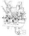
- FIG. 4is a view of a multi-zone jet adhesive dispenser assembly, according to one embodiment.
- FIG. 5shows details of the transport mechanism of a multi-zone jet adhesive dispenser assembly according to one embodiment.
- FIG. 6shows details of a machine vision system of a first zone of a multi-zone jet adhesive dispenser assembly according to one embodiment, showing a downward-looking camera.
- FIG. 7is a view of an adhesive tacking system, as may be present in a first or second zone of a multi-zone jet adhesive dispenser assembly according to one embodiment.
- FIG. 8is a table relating HGA long tail to HSA gap measurements to the number adhesive dots applied and the opening time of the jet adhesive dispenser, according to one embodiment.
- FIG. 9is a flowchart of a method according to one embodiment.
- HGA long tailsare adhesively tacked to HSA arms using a needle to contact both the actuator arm and the HGA long tail to dispense an amount of adhesive.
- the needlemay be disposed at a 45 degree angle relative to the HSA arms while dispensing the adhesive. In so doing, the dispensing needle pushes the HGA long tail sideways to ensure that the adhesive will contact both the HGA long tail and HSA arm. This process can disturb the HGA long tail and is lengthy, which negatively affects yields.
- FIG. 1shows the principal components of a magnetic disk drive 100 configured according to an embodiment of the present invention.
- the disk drive 100comprises a head disk assembly (HDA) 144 and a printed circuit board assembly (PCBA) 141 .
- the HDA 144includes a base 161 and a cover 171 attached to the base 161 that collectively house one or more disks 800 (only one disk 800 is shown in FIG. 1 ), a spindle motor 113 attached to the base 161 for rotating the disk 800 , a HSA 150 according to one embodiment, and a pivot bearing cartridge 184 that rotatably supports the HSA 150 on the base 161 .
- the spindle motor 113rotates the disk 800 at a substantially constant angular velocity.
- the HSA 150comprises a swing-type or rotary actuator assembly 152 , at least one HGA that includes the suspension assembly 154 , a flex circuit cable assembly 180 and a flex bracket 159 .
- the rotary actuator assembly 152includes a body portion 145 , at least one actuator arm cantilevered from the body portion 145 , and a coil assembly including a coil 156 cantilevered from the body portion 145 in an opposite direction from the actuator arm(s).
- a bobbin 158may be attached to the inner periphery of the coil assembly to stiffen the coil assembly.
- the actuator arm(s)support respective suspension assembly(ies) that, in turn, support the head that includes the read/write transducer(s) for reading and writing to the disk 100 .
- the HSA 150is pivotally secured to the base 161 via the pivot-bearing cartridge 184 so that the read/write transducer(s) at the distal end of the suspension assembly(ies) may be moved over the recording surface(s) of the disk(s) 100 .
- the pivot-bearing cartridge 184enables the HSA 150 to pivot about its pivot axis.
- the “rotary” or “swing-type” actuator assemblyrotates on the pivot bearing cartridge 184 between limited positions, and the coil assembly that extends from one side of the body portion 145 interacts with one or more permanent magnets 190 mounted to back irons 170 , 172 to form a voice coil motor (VCM).
- VCMvoice coil motor
- the headWhen a driving voltage is applied to the VCM, torque is developed that causes the HSA 150 to pivot about the actuator pivot axis and causes the read/write transducer(s) to sweep radially over the disk 800 .
- the headincludes a body called a “slider” that carries a magnetic transducer on its trailing end (not visible given the scale of FIG. 1 ).
- the magnetic transducermay include an inductive write element and a magnetoresistive read element. During operation, the transducer is separated from the magnetic disk by a very thin hydrodynamic air bearing.
- this hydrodynamic air bearingis formed between an air bearing surface of the slider of head 40 , and a surface of the magnetic disk 800 .
- the thickness of the air bearing at the location of the transduceris commonly referred to as “flying height.”
- One embodimentincludes a device configured to adaptively tack or apply adhesive between selected portions of the HGA and selected portions of the arms of the HSA.
- the location and amount of adhesive being appliedmay vary depending on the position and gap or distance between the selected portions of the HGA and the selected portions of the arm, as measured using a machine vision system.
- FIG. 2is a perspective view of a HSA comprising HGA long tail to HSA adhesive tacking points, according to one embodiment.
- FIG. 3is a side view of a HSA comprising HGA long tail to HSA adhesive tacking points, according to one embodiment.
- the HSA 200comprises an actuator assembly 204 that includes a plurality of actuator arms 205 .
- HGAs 202may be affixed to the actuator arms 205 through, for example, a ball swaging process.
- a selected portion of the HGAs 202may be secured to the actuator arms 205 using adhesive applied at selected points.
- the selected portions of the HGAs 202 that are to be secured to the actuator arms 205may include the long tails of the HGA, which include conductive traces to and from the read and write transducers.
- the HSA 200may comprise actuator arms 205 that, as best shown in FIG. 2 , define a plurality of adhesive tacking points 206 to which adhesive may be applied, to secure the selected portion of the HGA to a corresponding selected portion of the actuator arms 205 .
- the adhesive tacking points 206may be located at or near slots distributed along the length of the actuator arms 205 .
- the long tails of the HGAsmay span these slots, immediately adjacent thereto or may be separated therefrom by a small but measurable gap. These slots and the gaps between the HGA long tail may be imaged by a machine vision system in communication with an adhesive tacking system that is configured to selectively apply adhesive to secure the HGA long tails to the actuator arms 205 .
- FIG. 4is a view of a multi-zone jet adhesive dispenser assembly, according to one embodiment.
- the device or assembly 400may comprise a plurality of functional areas or zones. In the implementation of FIG. 4 , three zones are depicted.
- a transport mechanism, as shown at 402may be provided to transport the HSA under manufacture from zone to zone, as suggested by arrow 404 in FIG. 4 .
- the device 400may comprise a machine vision system 406 in a first zone of the device.
- the machine vision system 406may be configured to image the HSA under manufacture, process the captured image of the HSA and determine the selected location(s) where the adhesive is to be applied.
- the machine vision system 406may be configured to image the HSA and determine, from the captured image or images, locations on the actuator arms 205 and corresponding locations on the HGA to which adhesive is to be applied. In one embodiment, the machine vision system may determine, from the image(s) of the HSA, the locations of the adhesive tacking points 206 . The determined locations may be determined as x, y and z coordinates from an origin point.
- the machine vision system 406may be configured to determine the locations of the slots in the actuator arms 205 as well as measurements of gaps between selected portions of the HGA (such as the aforementioned long tails of the HGAs) and corresponding selected portions (such as the slots, for example) of the actuator arms 205 of the HSA 204 of a data storage device.
- the transport mechanism 402may comprise one or more motors and one or more rails to sequentially transport the HSAs under manufacture to the first zone to be imaged by the machine vision system 406 and from the first zone the second zone of the device 400 .
- the second zonemay comprise a first adhesive tacking system to apply adhesive to the gaps between the actuator arms 205 and the long tails of the HGAs 202 .
- the first adhesive tacking systemmay be configured to sequentially apply adhesive to the gaps based upon the measurements of the gaps provided by the machine vision system 406 .
- the multi-zone jet adhesive dispenser assembly 400may comprise a third zone.
- the third zonemay comprise a second adhesive tacking system, also be configured to apply adhesive to the gaps based upon the measurements of the gaps provided by the machine vision system 406 . That is, the first adhesive tacking system in the second zone may be configured to apply some of the adhesive necessary to secure the HGAs 202 to the actuator arms 205 and the second adhesive tacking system in the third zone may be configured to apply some more of the adhesive (or all remaining adhesive) necessary to secure the HGAs 202 to the actuator arms 205 .
- the transport mechanism 402may sequentially carry the HSA under manufacture from a previous manufacturing station to the first zone to enable the machine vision system 406 to locate and measure the gaps where the adhesive is to be applied and from the first zone to the second zone of the device to enable the first adhesive tacking system to apply adhesive to the located and measured gaps and from the second zone to the third zone to apply additional adhesive and/or to carry out other functions.
- the multi-zone jet adhesive dispenser assembly 400may comprise one or more microprocessors and/or controllers 122 and one or more volatile and/or non-volatile memory stores 124 .
- the memory 124may be configured to store sequences of instructions that, when executed by processor(s) 122 , cause the device 400 to carry out the functionality shown and described herein.
- FIG. 5shows details of the transport mechanism 402 of a multi-zone jet adhesive dispenser assembly according to one embodiment.
- the transport mechanism 402may comprise a plurality of movable platforms 502 , each configured to support an HSA under manufacture (not shown in FIG. 5 ).
- the movable platforms 502may be configured to roll along rails 504 and rollers 506 between the first zone, the second zone and the third zone of the multi-zone jet adhesive dispenser assembly.
- the platforms 502may be configured to transport the HSAs under manufacture from one zone to another and to stop at each zone.
- the transport mechanism 402may be configured to continuously transport the HSAs under manufacture from one zone to another, with the machine vision system and the adhesive tacking system(s) configured to image the moving HSAs and to apply the adhesive thereto in a non-contact manner, as the HSAs move from one zone to another.
- the machine vision system 406may comprise a downward-looking camera 602 and/or a side-looking camera 604 , configured to obtain sufficient views of the HSA transported to the first zone to enable it to accurately determine the location of adhesive tacking points 206 where the adhesive is to be applied and the width of the gaps between the actuator arms 205 and the HGA long tails. Cameras at other angles may be provided also, or in addition to those shown in FIG. 6 . Based upon the image or images obtained, the machine vision system may determine coordinates for the locations where the adhesive is to be applied, to secure the HGAs to the actuator arms 205 .
- the adhesive tacking systems of zones 1 and 2may be configured to move in at least two planes, apply adhesive to the gaps between the HGA and the facing surface of the actuator arm 205 at locations (at least partially) derived from one or more of the measurements provided by the machine vision system 406 .
- FIG. 7is a view of a portion of a jet adhesive dispenser according to one embodiment.
- FIG. 7shows a jet adhesive dispenser 702 , as may be present in zones 2 and/or 3 of the present multi-zone jet adhesive dispenser assembly.
- the jet adhesive dispenser 702may be configured to dispense adhesive in a non-contact manner (e.g., at a distance of about 2 mm from its target adhesive application location) as the cradled HSA 200 is moved thereunder. In this manner, the adhesive jet dispenser(s) may be configured to apply the adhesive to the gaps without contacting the HGA or the HSA of the data storage device.
- the jet adhesive dispenser 702 in one zonemay be configured to apply some of the required adhesive at some of the slots of the HSA arms 205 , while the jet adhesive dispenser in another zone may be configured to apply adhesive to remaining ones of the slots of the HSA arms 205 .
- Adhesivemay be applied simultaneously in zone 1 and in zone 2.
- FIG. 7shows a HSA cradle configured to orient and immobile the HSA 200 under manufacture on a movable platform 502 .
- the HSA cradlemay be configured to couple to the pivot bearing cartridge of the HSA 200 , as shown at 704 .
- the HSA cradlemay comprise a positioning pin 706 configured to abut the VCM arms 708 .
- spreaders 710may be configured to interdigitate between next adjacent ones of the actuator arms 205 and coupled HGAs to precisely spread and immobilize each of the actuator arms and HGAs. This also protects the sliders from damage during manufacture.
- the HSA cradlemay also comprise posts 712 against which the distal lift tabs may rest.
- the HSA under manufactureis both immobilized and properly oriented so that the machine vision system 406 and the adhesive tacking system(s) may image, determine the coordinates of slots of the HSA arms 205 and precisely apply adhesive, respectively.
- the adhesive tacking system in the first zone or in the second zonemay be configured to vary the amount of adhesive applied based upon one or more of the measurements provided by the machine vision system 406 .
- the machine vision systemmay be configured to measure the width of the gaps between the HGA long tail and the actuator arm 205 at the locations selected for adhesive application (e.g., the slots of actuator arm 205 ). In one embodiment, the measured width of the gap may determine the amount of adhesive applied thereto.
- the adhesive tacking systemmay be configured to apply the adhesive in the forms of “dots”, with each such dot comprising a predetermined amount of adhesive applied to one location. FIG.
- the adhesive tacking systems of zones and 2may be configured to apply a number of dots of adhesive to each of the gaps, with the number of dots of adhesive applied being based upon one or more of the measurements provided by the machine vision system 406 . Therefore, the amount of adhesive applied to any one location may be adaptive and based upon a measured width of the gap between the HGA long tail and the facing surface of the actuator arm 205 .
- the opening time of the jet adhesive dispenseris constant across all measured widths, but this need not be the case. For example, for large gap widths, a longer opening time may be necessary for the jet adhesive dispenser to have time to apply the needed amount of adhesive, whether in the form of adhesive dots or not.
- the adhesive tacking systems in zones 1 and 2may be configured to dispense an exact amount of adhesive depending on the gap or distance between the long tail of the HGA and the slots on the actuator arm 205 .
- the gap and location at which the adhesive is to be appliedmay be determined by the machine vision system 406 and the resulting measurements may then relayed to adhesive tacking systems in the first zone or in the second zone for on-the-fly adhesive dispensing.
- FIG. 9is a flowchart of a method according to one embodiment.
- the methodmay comprise transporting a HSA of a data storage device to a first zone of an adhesive tacking device, as shown at block B 91 .
- a machine vision systemin the first zone of the adhesive tacking device, the gaps between selected portions of a HGA and selected portions of arms of the HSA may be measured and the measurements thereof provided, as shown at B 92 .
- Block B 93calls for transporting the HSA from the first zone to a second zone of the adhesive tacking device.
- the adhesivemay then be sequentially applied, in the second zone of the adhesive tacking device, to the gaps based upon at least one of the measurements provided by the machine vision system, as called for by block B 94 .
- the amount of adhesive applied to the gapsmay be varied based upon one or more of the measurements provided by the machine vision system. For example, the number of dots of adhesive in each of the gaps may be varied, based upon one or more of the measurements provided by the machine vision system. Also, the adhesive may be applied at locations derived (or at least partially derived) from the or some of the measurements provided by the machine vision system. According to one embodiment, the application of the adhesive to the gaps may be carried out without contacting the HGA or the HSA of the data storage device. The adhesive may be applied to the gaps, according to one embodiment, for an amount of time that may be at least partially derived from one or more of the measurements provided by the machine vision system.
- the adhesive dispenser of the adhesive tacking devicemay be moved in planes parallel to the x, y and/or z axes to apply the adhesive to the gaps at locations that may be at least partially derived from one or more of the measurements provided by the machine vision system.
- One embodimentincludes transporting the HSA of the data storage device from the second zone to a third zone of the adhesive tacking device and applying further adhesive to the gaps in the third zone of the adhesive tacking device based upon one or more of the measurements provided by the machine vision system.
- measuringmay include taking an image of the HSA after the HSA has been transported to the first zone of the adhesive tacking device and analyzing the image to provide the measurements of the gaps.
- an adhesive tacking devicemay comprise a machine vision system in a first zone of the device, a first adhesive tacking system in a second zone of the device, a transport mechanism, a processor such as shown at 122 in FIG. 4 and a memory, as shown at reference 124 , coupled to the memory 124 the memory storing sequences of instructions that, when executed by the processor 122 , cause the device to carry out the steps and functionality shown in FIG. 9 and described herein.
- the devices and methods disclosed hereinare able to achieve a faster adhesive tacking process to meet stringent HSA automation line cycle time requirements, thereby increasing yield and decreasing costs.
- the adhesiveaccording to one embodiment, is also more accurately dispensed, leading to a more consistent adhesive HGA long tail to actuator arm tacking process.
- the non-contact adhesive dispensing of the adhesive tacking systemsallows for safer processes that are less likely to lead to damaging electrical static discharge (ESD) damage.
- ESDelectrical static discharge
Landscapes
- Physics & Mathematics (AREA)
- General Physics & Mathematics (AREA)
- Supporting Of Heads In Record-Carrier Devices (AREA)
Abstract
Description
Claims (19)
Priority Applications (1)
| Application Number | Priority Date | Filing Date | Title |
|---|---|---|---|
| US14/752,646US9286922B1 (en) | 2015-06-26 | 2015-06-26 | Adaptive tacking of head gimbal assembly long tail and HSA arm slot |
Applications Claiming Priority (1)
| Application Number | Priority Date | Filing Date | Title |
|---|---|---|---|
| US14/752,646US9286922B1 (en) | 2015-06-26 | 2015-06-26 | Adaptive tacking of head gimbal assembly long tail and HSA arm slot |
Publications (1)
| Publication Number | Publication Date |
|---|---|
| US9286922B1true US9286922B1 (en) | 2016-03-15 |
Family
ID=55450205
Family Applications (1)
| Application Number | Title | Priority Date | Filing Date |
|---|---|---|---|
| US14/752,646Expired - Fee RelatedUS9286922B1 (en) | 2015-06-26 | 2015-06-26 | Adaptive tacking of head gimbal assembly long tail and HSA arm slot |
Country Status (1)
| Country | Link |
|---|---|
| US (1) | US9286922B1 (en) |
Cited By (2)
| Publication number | Priority date | Publication date | Assignee | Title |
|---|---|---|---|---|
| CN108331816A (en)* | 2017-01-20 | 2018-07-27 | 富鼎电子科技(嘉善)有限公司 | Assembling device |
| CN109869390A (en)* | 2019-04-03 | 2019-06-11 | 余姚泰速自动化科技有限公司 | A kind of automatic moulding equipment of ultrasonic bonding |
Citations (122)
| Publication number | Priority date | Publication date | Assignee | Title |
|---|---|---|---|---|
| US5505777A (en) | 1992-11-19 | 1996-04-09 | Asymptotic Technologies, Inc. | Computer controlled viscous fluid dispensing system |
| US6049973A (en) | 1999-04-12 | 2000-04-18 | Western Digital Corporation | Method of assembling an integrated computer module |
| US6271996B1 (en) | 1997-11-10 | 2001-08-07 | Hutchinson Technology Incorporated | Damper with unconstrained surface for a disk drive head suspension |
| US20020038506A1 (en)* | 2000-09-19 | 2002-04-04 | Takehiro Kamigama | Manufacturing method of head arm assembly |
| US6467153B2 (en) | 1997-06-11 | 2002-10-22 | Western Digital Technologies, Inc. | Method for manufacturing a disk drive |
| US20020181157A1 (en) | 2001-04-18 | 2002-12-05 | Dai Nippon Printing Co., Ltd. | Magnetic head suspension and method of fabricating the same |
| US6651192B1 (en) | 2000-11-30 | 2003-11-18 | Western Digital Technologies, Inc. | Method and system for testing reliability attributes in disk drives |
| US6657801B1 (en) | 2002-09-30 | 2003-12-02 | Western Digital Technologies, Inc. | Disk drive with improved characterization segment pattern and method of recording the same |
| US20040012891A1 (en)* | 2001-12-04 | 2004-01-22 | Masao Habe | FPC mounting apparatus |
| US6687093B1 (en) | 2001-05-31 | 2004-02-03 | Western Digital Technologies, Inc. | Head stack assembly shipping comb with temporary locating feature for internal head disk assembly build process and disk drive manufactured using the same |
| US6751041B1 (en) | 2002-01-31 | 2004-06-15 | Western Digital Technologies, Inc. | Method and apparatus for selecting servo track writing speed |
| US6779252B2 (en)* | 1999-02-17 | 2004-08-24 | Applied Kinetics, Inc. | Apparatus for assembling components |
| US6788480B1 (en) | 2001-12-22 | 2004-09-07 | Western Digital Technologies, Inc. | Method and apparatus for determining track density during a servo-track writing operation |
| US6791782B1 (en) | 2002-01-31 | 2004-09-14 | Western Digital Technologies, Inc. | Method and apparatus for determining operational spindle rotation rate in a disk drive |
| US6792669B2 (en) | 2001-11-30 | 2004-09-21 | Western Digital Technologies, Inc. | Method for allocating disk drive spindle motors based on an operating characteristic |
| US6798592B1 (en) | 2001-08-31 | 2004-09-28 | Western Digital Technologies, Inc. | Method for reducing position error signal in a disk drive |
| US20050013055A1 (en)* | 2003-07-18 | 2005-01-20 | Yiu Sing Ho | Method of head stack assembly flexible circuit assembly attached to an actuator arm |
| US6894861B1 (en) | 2001-09-28 | 2005-05-17 | Western Digital Technologies, Inc. | Method for reducing written-in runout during servo track writing of a disk drive |
| US6897393B1 (en) | 2002-04-30 | 2005-05-24 | Western Digital Technologies, Inc. | Methods for reducing costs and increasing throughput in the manufacture of disk drives by categorizing the disk drives based upon measured disk pack imbalance |
| US6898044B1 (en) | 2003-04-30 | 2005-05-24 | Western Digital Technologies, Inc. | Method for calculating a format specific parameter in a disk drive having differing surface formats |
| US6943972B1 (en) | 2003-06-27 | 2005-09-13 | Western Digital Technologies, Inc. | Selecting a track density for each disk surface of a disk drive based on head characteristic |
| US20050235510A1 (en)* | 2004-04-21 | 2005-10-27 | Riospring, Inc. | Inspection fixture |
| US7003626B1 (en) | 2003-05-30 | 2006-02-21 | Western Digital Technologies, Inc. | Method for storing format specific data in a microcontroller execution memory |
| US7027242B1 (en) | 2004-09-23 | 2006-04-11 | Western Digital (Fremont), Inc. | Method and apparatus for measuring write-induced pole tip protrusion |
| US7046467B1 (en) | 2003-04-30 | 2006-05-16 | Western Digital Technologies, Inc. | Method for generating a format specific data structure in a disk drive having differing surface formats |
| US7058759B1 (en) | 2003-03-31 | 2006-06-06 | Western Digital Technologies, Inc. | Configuring a disk drive to support a targeted storage format |
| US7072129B1 (en) | 2004-06-30 | 2006-07-04 | Western Digital Technologies, Inc. | Identifying defective data sectors in a disk drive |
| US7076603B1 (en) | 2003-03-31 | 2006-07-11 | Western Digital Technologies, Inc. | Method for mapping a selected sector to a zone on a disk |
| US7076391B1 (en) | 2002-10-31 | 2006-07-11 | Western Digital Technologies, Inc. | Methods and systems for asynchronously testing a plurality of disk drives |
| US7136242B1 (en) | 2004-12-09 | 2006-11-14 | Western Digital Technologies, Inc. | Servo writing substantially linear servo wedges to reduce overwrite effect in perpendicular magnetic recording |
| US7139145B1 (en) | 2004-09-23 | 2006-11-21 | Western Digital Technologies, Inc. | Cluster-based defect detection testing for disk drives |
| US7145744B1 (en) | 2005-08-03 | 2006-12-05 | Western Digital Technologies, Inc. | Reducing spiral write time and clock track drift while writing spiral reference patterns to a disk of a disk drive |
| US7178432B1 (en) | 2005-11-30 | 2007-02-20 | Western Digital Technologies, Inc. | Methods, devices and systems for screw feeding by vacuum and gravity |
| US7199959B1 (en) | 2004-12-13 | 2007-04-03 | Western Digital Technologies, Inc. | Repeatable timing error correction system for use in a servo writer |
| US7203020B1 (en) | 2005-10-07 | 2007-04-10 | Western Digital Technologies, Inc. | System and method for particle monitoring for a head disk assembly to detect a head disk interface event |
| US7209310B1 (en) | 2005-07-25 | 2007-04-24 | Western Digital Technologies, Inc. | Disk drive identifying starting track by performing multiple load operations |
| US7222410B1 (en) | 2004-10-27 | 2007-05-29 | Western Digital Technologies, Inc. | Method of assembly of a disk drive including engaging first and second VCM plates while maintaining a holding force against the first VCM plate |
| US7236911B1 (en) | 2004-06-16 | 2007-06-26 | Western Digital Technologies, Inc. | Using a genetic algorithm to select a subset of quality metrics as input to a disk drive failure prediction algorithm |
| US7269525B1 (en) | 2004-06-16 | 2007-09-11 | Western Digital Technologies, Inc. | Binning disk drives during manufacturing by evaluating quality metrics prior to a final quality audit |
| US20080084630A1 (en) | 2006-10-05 | 2008-04-10 | Western Digital Technologies, Inc. | Media cover for manufacturing a disk drive |
| US7458282B1 (en) | 2006-11-21 | 2008-12-02 | Western Digital Technologies, Inc. | Screwdriver comprising a slider having an attached screw bit and a position detector for position feedback |
| US7490398B1 (en)* | 2006-02-22 | 2009-02-17 | Western Digital Technologies, Inc. | Methods for assembling a disk drive using robotic end effector |
| US7506553B1 (en) | 2007-06-18 | 2009-03-24 | Western Digital Technologies, Inc. | Methods, devices and systems for adaptively driving screws using a screw driving tool |
| US20090157848A1 (en) | 2007-12-18 | 2009-06-18 | Western Digital Technologies, Inc. | Application server processing tcp/ip requests from a client by invoking an asynchronous function |
| US7549204B1 (en) | 2005-11-30 | 2009-06-23 | Western Digital Technologies, Inc. | Methods for picking and placing workpieces into small form factor hard disk drives |
| US7552526B1 (en) | 2005-01-12 | 2009-06-30 | Western Digital Technologies, Inc. | Tooling mandrel for assembling a head stack assembly with a disk drive base |
| US7559590B1 (en) | 2005-10-19 | 2009-07-14 | Western Digital Technologies, Inc. | Pressure transmission assembly for mounting to a robotic device having a rotatable end effector |
| US7561416B1 (en) | 2006-12-15 | 2009-07-14 | Western Digital Technologies, Inc. | Storage device fixture with simultaneous unload mechanism |
| US7596722B1 (en) | 2006-02-14 | 2009-09-29 | Western Digital Technologies, Inc. | Asynchronous automatic software module updates in a multi-cell disk drive test system |
| US7634375B1 (en) | 2002-10-31 | 2009-12-15 | Western Digital Technologies, Inc. | Multi-drive adaptor for use in a slot of a disk drive test system |
| US7653983B1 (en) | 2007-06-26 | 2010-02-02 | Western Digital Technologies, Inc. | Manufacturing assembly for manufacturing a disk drive |
| US7669711B1 (en) | 2005-10-19 | 2010-03-02 | Western Digital Technologies, Inc. | Disk pack balancing station |
| US7671599B1 (en) | 2007-01-31 | 2010-03-02 | Western Digital Technologies, Inc. | Static electricity monitor comprising a walking footpad electrode and handrail electrode |
| US7673638B1 (en) | 2006-06-16 | 2010-03-09 | Western Digital Technologies, Inc. | System and method to monitor particles removed from a component |
| US7690705B1 (en) | 2006-12-21 | 2010-04-06 | Western Digital Technologies, Inc. | Vacuum chuck useful for affixing cover seals to hard disk drives |
| US20100108256A1 (en) | 2008-11-05 | 2010-05-06 | Western Digital Technologies, Inc. | Closed loop control of adhesive dot characteristics |
| US20100178433A1 (en) | 2009-01-14 | 2010-07-15 | Gm Global Technology Operations, Inc. | Method and apparatus for applying bonding adhesive |
| US7863889B1 (en) | 2007-02-06 | 2011-01-04 | Western Digital Technologies, Inc. | Component receptacle to segregate components |
| US7869182B1 (en) | 2006-08-23 | 2011-01-11 | Western Digital Technologies, Inc. | Monitoring device for use with an insulated dual portion garment |
| US7896218B2 (en) | 2007-06-28 | 2011-03-01 | Western Digital Technologies, Inc. | Apparatus and method for conductive metal ball bonding with electrostatic discharge detection |
| US7900272B1 (en) | 2006-08-23 | 2011-03-08 | Western Digital Technologies, Inc. | Static control garment |
| US7912666B1 (en) | 2005-11-28 | 2011-03-22 | Western Digital Technologies, Inc. | Disk drive grouping in a multi-cell disk drive test system |
| US7916599B1 (en) | 2008-05-23 | 2011-03-29 | Western Digital Technologies, Inc. | Method to balance spindles in a plurality of disk drives |
| US7940487B1 (en) | 2008-06-24 | 2011-05-10 | Western Digital Technologies, Inc. | Heating a head disk assembly for a time interval prior to writing spiral servo tracks to the disk |
| US7974038B2 (en) | 2007-12-10 | 2011-07-05 | Western Digital Technologies, Inc. | Servo writer with retract capacitor for generating a VCM driving current during a power failure |
| US7980159B1 (en) | 2005-11-30 | 2011-07-19 | Western Digital Technologies, Inc. | Methods, devices and systems for screw feeding by vacuum and gravity |
| US8078421B1 (en) | 2007-12-19 | 2011-12-13 | Western Digital Technologies, Inc. | Multi-cell disk drive test system providing a power recovery mode |
| US8094414B1 (en) | 2009-07-09 | 2012-01-10 | Western Digital Technologies, Inc. | Head gimbal assembly mounting mechanism |
| US8092610B1 (en) | 2010-12-21 | 2012-01-10 | Western Digital Technologies, Inc. | Apparatus and method for cleaning a driver used in disk drive manufacturing |
| US8098460B1 (en) | 2009-06-30 | 2012-01-17 | Western Digital Technologies, Inc. | Dual-state clamping mechanism |
| US8135208B1 (en) | 2009-01-15 | 2012-03-13 | Western Digital Technologies, Inc. | Calibrated vision based robotic system utilizing upward and downward looking cameras |
| US8162366B1 (en) | 2010-03-26 | 2012-04-24 | Western Digital Technologies, Inc. | Systems and methods for gripping a component |
| US8168033B1 (en) | 2007-06-12 | 2012-05-01 | Western Digital Technologies, Inc. | Methods and devices for printing and affixing an individual label onto an item having a machine readable code thereon |
| US8180487B1 (en) | 2008-09-30 | 2012-05-15 | Western Digital Technologies, Inc. | Calibrated vision based robotic system |
| US8199425B1 (en) | 2009-05-29 | 2012-06-12 | Western Digital Technologies, Inc. | Method to replace gas in a disk drive |
| US8218256B1 (en) | 2009-10-30 | 2012-07-10 | Western Digital Technologies, Inc. | Disk spindle assembly cartridge |
| US8223448B1 (en) | 2010-04-22 | 2012-07-17 | Western Digital Technologies, Inc. | Disk drive calibrating preamp for servo sectors and data sectors |
| US8233243B2 (en) | 2008-12-10 | 2012-07-31 | Seagate Technology Llc | Head suspension assembly interconnect for a data storage device |
| US8230570B1 (en) | 2009-06-12 | 2012-07-31 | Western Digital Technologies, Inc. | Automatic gravity vacuum screw feeding |
| US20120200287A1 (en)* | 2009-10-22 | 2012-08-09 | Xyratex Technology Limited | Spinstands for testing a head gimbal assembly |
| US8245601B1 (en) | 2010-03-31 | 2012-08-21 | Western Digital Technologies, Inc. | Screwdriver sleeve finder |
| US8267831B1 (en) | 2009-05-19 | 2012-09-18 | Western Digital Technologies, Inc. | Method and apparatus for washing, etching, rinsing, and plating substrates |
| US8270118B1 (en) | 2009-10-30 | 2012-09-18 | Western Digital Technologies, Inc. | Head stack assembly cartridge |
| US8300338B1 (en) | 2010-09-30 | 2012-10-30 | Western Digital Technologies, Inc. | Disk drive correlating different fly height measurements to verify disk warpage |
| US8307537B1 (en) | 2005-10-24 | 2012-11-13 | Western Digital Technologies, Inc. | Method of using a tooling mandrel for assembling a disk drive |
| US8322235B1 (en) | 2011-02-18 | 2012-12-04 | Western Digital Technologies, Inc. | Microactuator test assembly comprising a spreader pin for engaging a load beam of an actuator arm |
| US8327529B1 (en) | 2010-06-04 | 2012-12-11 | Western Digital Technologies, Inc. | Assembly tool system |
| US8335049B1 (en) | 2010-06-07 | 2012-12-18 | Western Digital Technologies, Inc. | Disk drive detecting crack in microactuator |
| US8345367B1 (en) | 2010-12-23 | 2013-01-01 | Western Digital Technologies, Inc. | Recording defects on a hard drive |
| US8356384B1 (en) | 2010-06-30 | 2013-01-22 | Western Digital Technologies, Inc. | Hard drive assembly tools for evacuating particles |
| US8369073B2 (en) | 2010-09-30 | 2013-02-05 | Western Digital Technologies, Inc. | Systems and methods for connecting multiple hard drives |
| US8379363B1 (en) | 2010-03-26 | 2013-02-19 | Western Digital Technologies, Inc. | Bulk erase tool to erase a perpendicular media recording disk of a disk drive |
| US8387631B1 (en) | 2008-12-10 | 2013-03-05 | Western Digital Technologies, Inc. | HDA vacuum cleaning machine for manufacturing of HDD |
| US20130057986A1 (en) | 2011-09-06 | 2013-03-07 | Western Digital Technologies, Inc. | System and method to align a boss of a head gimbal assembly to a boss hole of an actuator arm for disk drive assembly |
| US8424824B1 (en) | 2009-12-22 | 2013-04-23 | Western Digital Technologies, Inc. | Balancer swivel arm assembly |
| US8424418B1 (en) | 2010-09-30 | 2013-04-23 | Western Digital Technologies, Inc. | Systems and methods for coupling screwdrivers to screw finders |
| US8432630B1 (en) | 2010-06-30 | 2013-04-30 | Western Digital Technologies, Inc. | Disk drive component test system |
| US8447551B1 (en) | 2010-06-30 | 2013-05-21 | Western Digital Technologies, Inc. | Hard drive assembly tool calibration verification |
| US8447430B1 (en) | 2010-06-30 | 2013-05-21 | Western Digital Technologies, Inc. | Systems and methods for assembly tool calibration verification |
| US8451578B1 (en) | 2010-02-12 | 2013-05-28 | Western Digital Technologies, Inc. | Hard drive particle cleaning system and method |
| US8453841B1 (en) | 2009-04-23 | 2013-06-04 | Western Digital Technologies, Inc. | Disk placement and storage assembly with disk cassette and disk slotter |
| US8485772B1 (en) | 2010-02-24 | 2013-07-16 | Western Digital Technologies, Inc. | Media flip and cassette exchange apparatus and method |
| US8493681B1 (en) | 2010-11-23 | 2013-07-23 | Western Digital Technologies, Inc. | Disk drive generating map of margin rectangles around defects |
| US8537480B1 (en) | 2010-11-23 | 2013-09-17 | Western Digital Technologies, Inc. | Hard drive testing |
| US20130248545A1 (en) | 2012-03-23 | 2013-09-26 | Western Digital Technologies, Inc. | Fastener container to provide fasteners to a fastener feeder |
| US8547657B1 (en) | 2010-06-10 | 2013-10-01 | Western Digital Technologies, Inc. | Disk drive detecting defective microactuator |
| US8553968B1 (en) | 2005-02-18 | 2013-10-08 | Western Digital Technologies, Inc. | Using optical character recognition augmented by an error correction code to detect serial numbers written on a wafer |
| US8565511B1 (en) | 2010-12-22 | 2013-10-22 | Western Digital Technologies, Inc. | Apparatus and method to align a manufacturing device having an end effecter and fixture in a parallel manner |
| US8582229B1 (en) | 2010-09-27 | 2013-11-12 | Western Digital Technologies, Inc. | Pushpin assembly |
| US8596107B1 (en) | 2010-03-30 | 2013-12-03 | Western Digital Technologies, Inc. | Correlation standard for calibrating a scanning electron microscope |
| US8605383B1 (en) | 2012-05-21 | 2013-12-10 | Western Digital Technologies, Inc. | Methods, devices and systems for characterizing polarities of piezoelectric (PZT) elements of a two PZT element microactuator |
| US8640328B1 (en) | 2010-06-18 | 2014-02-04 | Western Digital Technologies, Inc. | Systems for fastening a head stack to a hard drive base assembly |
| US8653824B1 (en) | 2009-12-16 | 2014-02-18 | Western Digital (Fremont), Llc | Delta temperature test method and system |
| US8650716B1 (en) | 2011-12-13 | 2014-02-18 | Western Digital Technologies, Inc. | Methods and apparatus for minimizing contamination in hard disk drive assembly processes |
| US8662554B1 (en) | 2011-12-20 | 2014-03-04 | Western Digital Technologies, Inc. | Vacuum pick-up end effecter to pick and place a component in a manufacturing process |
| US8683676B1 (en) | 2011-04-29 | 2014-04-01 | Western Digital Technologies, Inc. | Apparatus and method to grip a disk clamp of a disk drive |
| US8707531B1 (en) | 2009-10-22 | 2014-04-29 | Western Digital Technologies, Inc. | Storage device assembly fixture |
| US8713333B1 (en) | 2011-03-24 | 2014-04-29 | Western Digital Technologies, Inc. | Apparatus and method to simulate a power trip to a disk drive |
| US8763790B1 (en) | 2011-05-25 | 2014-07-01 | Western Digital Technologies, Inc. | Clean room roller conveyor with motors between and torquing drive roller pairs |
| US8789446B1 (en) | 2011-06-28 | 2014-07-29 | Western Digital Technologies, Inc. | Screw feeding apparatus to deliver a screw from a vibrating rail to a screw guide tube |
| US8811135B1 (en) | 2012-03-20 | 2014-08-19 | Western Digital Technologies, Inc. | Disk drive component flow fixture |
| US8869385B2 (en)* | 2007-09-24 | 2014-10-28 | HGST Netherlands B.V. | Apparatus for positioning components in HDD |
- 2015
- 2015-06-26USUS14/752,646patent/US9286922B1/ennot_activeExpired - Fee Related
Patent Citations (136)
| Publication number | Priority date | Publication date | Assignee | Title |
|---|---|---|---|---|
| US5505777A (en) | 1992-11-19 | 1996-04-09 | Asymptotic Technologies, Inc. | Computer controlled viscous fluid dispensing system |
| US6467153B2 (en) | 1997-06-11 | 2002-10-22 | Western Digital Technologies, Inc. | Method for manufacturing a disk drive |
| US6271996B1 (en) | 1997-11-10 | 2001-08-07 | Hutchinson Technology Incorporated | Damper with unconstrained surface for a disk drive head suspension |
| US6779252B2 (en)* | 1999-02-17 | 2004-08-24 | Applied Kinetics, Inc. | Apparatus for assembling components |
| US6049973A (en) | 1999-04-12 | 2000-04-18 | Western Digital Corporation | Method of assembling an integrated computer module |
| US20020038506A1 (en)* | 2000-09-19 | 2002-04-04 | Takehiro Kamigama | Manufacturing method of head arm assembly |
| US6651192B1 (en) | 2000-11-30 | 2003-11-18 | Western Digital Technologies, Inc. | Method and system for testing reliability attributes in disk drives |
| US20020181157A1 (en) | 2001-04-18 | 2002-12-05 | Dai Nippon Printing Co., Ltd. | Magnetic head suspension and method of fabricating the same |
| US6687093B1 (en) | 2001-05-31 | 2004-02-03 | Western Digital Technologies, Inc. | Head stack assembly shipping comb with temporary locating feature for internal head disk assembly build process and disk drive manufactured using the same |
| US6798592B1 (en) | 2001-08-31 | 2004-09-28 | Western Digital Technologies, Inc. | Method for reducing position error signal in a disk drive |
| US6894861B1 (en) | 2001-09-28 | 2005-05-17 | Western Digital Technologies, Inc. | Method for reducing written-in runout during servo track writing of a disk drive |
| US6792669B2 (en) | 2001-11-30 | 2004-09-21 | Western Digital Technologies, Inc. | Method for allocating disk drive spindle motors based on an operating characteristic |
| US20040012891A1 (en)* | 2001-12-04 | 2004-01-22 | Masao Habe | FPC mounting apparatus |
| US6788480B1 (en) | 2001-12-22 | 2004-09-07 | Western Digital Technologies, Inc. | Method and apparatus for determining track density during a servo-track writing operation |
| US6751041B1 (en) | 2002-01-31 | 2004-06-15 | Western Digital Technologies, Inc. | Method and apparatus for selecting servo track writing speed |
| US6791782B1 (en) | 2002-01-31 | 2004-09-14 | Western Digital Technologies, Inc. | Method and apparatus for determining operational spindle rotation rate in a disk drive |
| US6897393B1 (en) | 2002-04-30 | 2005-05-24 | Western Digital Technologies, Inc. | Methods for reducing costs and increasing throughput in the manufacture of disk drives by categorizing the disk drives based upon measured disk pack imbalance |
| US6657801B1 (en) | 2002-09-30 | 2003-12-02 | Western Digital Technologies, Inc. | Disk drive with improved characterization segment pattern and method of recording the same |
| US7634375B1 (en) | 2002-10-31 | 2009-12-15 | Western Digital Technologies, Inc. | Multi-drive adaptor for use in a slot of a disk drive test system |
| US7076391B1 (en) | 2002-10-31 | 2006-07-11 | Western Digital Technologies, Inc. | Methods and systems for asynchronously testing a plurality of disk drives |
| US7058759B1 (en) | 2003-03-31 | 2006-06-06 | Western Digital Technologies, Inc. | Configuring a disk drive to support a targeted storage format |
| US7076603B1 (en) | 2003-03-31 | 2006-07-11 | Western Digital Technologies, Inc. | Method for mapping a selected sector to a zone on a disk |
| US7046467B1 (en) | 2003-04-30 | 2006-05-16 | Western Digital Technologies, Inc. | Method for generating a format specific data structure in a disk drive having differing surface formats |
| US6898044B1 (en) | 2003-04-30 | 2005-05-24 | Western Digital Technologies, Inc. | Method for calculating a format specific parameter in a disk drive having differing surface formats |
| US7003626B1 (en) | 2003-05-30 | 2006-02-21 | Western Digital Technologies, Inc. | Method for storing format specific data in a microcontroller execution memory |
| US6943972B1 (en) | 2003-06-27 | 2005-09-13 | Western Digital Technologies, Inc. | Selecting a track density for each disk surface of a disk drive based on head characteristic |
| US20050013055A1 (en)* | 2003-07-18 | 2005-01-20 | Yiu Sing Ho | Method of head stack assembly flexible circuit assembly attached to an actuator arm |
| US20050235510A1 (en)* | 2004-04-21 | 2005-10-27 | Riospring, Inc. | Inspection fixture |
| US7236911B1 (en) | 2004-06-16 | 2007-06-26 | Western Digital Technologies, Inc. | Using a genetic algorithm to select a subset of quality metrics as input to a disk drive failure prediction algorithm |
| US7269525B1 (en) | 2004-06-16 | 2007-09-11 | Western Digital Technologies, Inc. | Binning disk drives during manufacturing by evaluating quality metrics prior to a final quality audit |
| US7072129B1 (en) | 2004-06-30 | 2006-07-04 | Western Digital Technologies, Inc. | Identifying defective data sectors in a disk drive |
| US7027242B1 (en) | 2004-09-23 | 2006-04-11 | Western Digital (Fremont), Inc. | Method and apparatus for measuring write-induced pole tip protrusion |
| US7139145B1 (en) | 2004-09-23 | 2006-11-21 | Western Digital Technologies, Inc. | Cluster-based defect detection testing for disk drives |
| US7222410B1 (en) | 2004-10-27 | 2007-05-29 | Western Digital Technologies, Inc. | Method of assembly of a disk drive including engaging first and second VCM plates while maintaining a holding force against the first VCM plate |
| US7136242B1 (en) | 2004-12-09 | 2006-11-14 | Western Digital Technologies, Inc. | Servo writing substantially linear servo wedges to reduce overwrite effect in perpendicular magnetic recording |
| US7199959B1 (en) | 2004-12-13 | 2007-04-03 | Western Digital Technologies, Inc. | Repeatable timing error correction system for use in a servo writer |
| US7743486B1 (en) | 2005-01-12 | 2010-06-29 | Western Digital Technologies, Inc. | Method for assembling a head stack assembly with a disk drive base utilizing a tooling mandrel |
| US7552526B1 (en) | 2005-01-12 | 2009-06-30 | Western Digital Technologies, Inc. | Tooling mandrel for assembling a head stack assembly with a disk drive base |
| US8553968B1 (en) | 2005-02-18 | 2013-10-08 | Western Digital Technologies, Inc. | Using optical character recognition augmented by an error correction code to detect serial numbers written on a wafer |
| US7209310B1 (en) | 2005-07-25 | 2007-04-24 | Western Digital Technologies, Inc. | Disk drive identifying starting track by performing multiple load operations |
| US7145744B1 (en) | 2005-08-03 | 2006-12-05 | Western Digital Technologies, Inc. | Reducing spiral write time and clock track drift while writing spiral reference patterns to a disk of a disk drive |
| US7203020B1 (en) | 2005-10-07 | 2007-04-10 | Western Digital Technologies, Inc. | System and method for particle monitoring for a head disk assembly to detect a head disk interface event |
| US7559590B1 (en) | 2005-10-19 | 2009-07-14 | Western Digital Technologies, Inc. | Pressure transmission assembly for mounting to a robotic device having a rotatable end effector |
| US7874424B1 (en) | 2005-10-19 | 2011-01-25 | Western Digital Technologies, Inc. | Disk pack balancing station |
| US7669711B1 (en) | 2005-10-19 | 2010-03-02 | Western Digital Technologies, Inc. | Disk pack balancing station |
| US8307537B1 (en) | 2005-10-24 | 2012-11-13 | Western Digital Technologies, Inc. | Method of using a tooling mandrel for assembling a disk drive |
| US7912666B1 (en) | 2005-11-28 | 2011-03-22 | Western Digital Technologies, Inc. | Disk drive grouping in a multi-cell disk drive test system |
| US7980159B1 (en) | 2005-11-30 | 2011-07-19 | Western Digital Technologies, Inc. | Methods, devices and systems for screw feeding by vacuum and gravity |
| US7549204B1 (en) | 2005-11-30 | 2009-06-23 | Western Digital Technologies, Inc. | Methods for picking and placing workpieces into small form factor hard disk drives |
| US8561285B1 (en) | 2005-11-30 | 2013-10-22 | Western Digital Technologies, Inc. | Methods and devices for picking and placing workpieces into small form factor hard disk drives |
| US7178432B1 (en) | 2005-11-30 | 2007-02-20 | Western Digital Technologies, Inc. | Methods, devices and systems for screw feeding by vacuum and gravity |
| US8127643B1 (en) | 2005-11-30 | 2012-03-06 | Western Digital Technologies, Inc. | Methods, devices and systems for screw feeding by vacuum and gravity |
| US7596722B1 (en) | 2006-02-14 | 2009-09-29 | Western Digital Technologies, Inc. | Asynchronous automatic software module updates in a multi-cell disk drive test system |
| US7987585B1 (en) | 2006-02-22 | 2011-08-02 | Western Digital Technologies, Inc. | System for assembling a disk drive using a robotic end effector |
| US7490398B1 (en)* | 2006-02-22 | 2009-02-17 | Western Digital Technologies, Inc. | Methods for assembling a disk drive using robotic end effector |
| US7673638B1 (en) | 2006-06-16 | 2010-03-09 | Western Digital Technologies, Inc. | System and method to monitor particles removed from a component |
| US7869182B1 (en) | 2006-08-23 | 2011-01-11 | Western Digital Technologies, Inc. | Monitoring device for use with an insulated dual portion garment |
| US7869183B1 (en) | 2006-08-23 | 2011-01-11 | Western Digital Technologies, Inc. | Static electricity monitoring device comprising a first footpad electrically insulated from a second footpad |
| US7900272B1 (en) | 2006-08-23 | 2011-03-08 | Western Digital Technologies, Inc. | Static control garment |
| US7921543B2 (en) | 2006-10-05 | 2011-04-12 | Western Digital Technologies, Inc. | Method of manufacturing a disk drive using a media cover |
| US20080084630A1 (en) | 2006-10-05 | 2008-04-10 | Western Digital Technologies, Inc. | Media cover for manufacturing a disk drive |
| US7458282B1 (en) | 2006-11-21 | 2008-12-02 | Western Digital Technologies, Inc. | Screwdriver comprising a slider having an attached screw bit and a position detector for position feedback |
| US7561416B1 (en) | 2006-12-15 | 2009-07-14 | Western Digital Technologies, Inc. | Storage device fixture with simultaneous unload mechanism |
| US7690705B1 (en) | 2006-12-21 | 2010-04-06 | Western Digital Technologies, Inc. | Vacuum chuck useful for affixing cover seals to hard disk drives |
| US7671599B1 (en) | 2007-01-31 | 2010-03-02 | Western Digital Technologies, Inc. | Static electricity monitor comprising a walking footpad electrode and handrail electrode |
| US7863889B1 (en) | 2007-02-06 | 2011-01-04 | Western Digital Technologies, Inc. | Component receptacle to segregate components |
| US8168033B1 (en) | 2007-06-12 | 2012-05-01 | Western Digital Technologies, Inc. | Methods and devices for printing and affixing an individual label onto an item having a machine readable code thereon |
| US7506553B1 (en) | 2007-06-18 | 2009-03-24 | Western Digital Technologies, Inc. | Methods, devices and systems for adaptively driving screws using a screw driving tool |
| US7653983B1 (en) | 2007-06-26 | 2010-02-02 | Western Digital Technologies, Inc. | Manufacturing assembly for manufacturing a disk drive |
| US7896218B2 (en) | 2007-06-28 | 2011-03-01 | Western Digital Technologies, Inc. | Apparatus and method for conductive metal ball bonding with electrostatic discharge detection |
| US8066171B1 (en) | 2007-06-28 | 2011-11-29 | Western Digital Technologies, Inc. | Conductive metal ball bonding with electrostatic discharge detection |
| US8869385B2 (en)* | 2007-09-24 | 2014-10-28 | HGST Netherlands B.V. | Apparatus for positioning components in HDD |
| US7974038B2 (en) | 2007-12-10 | 2011-07-05 | Western Digital Technologies, Inc. | Servo writer with retract capacitor for generating a VCM driving current during a power failure |
| US20090157848A1 (en) | 2007-12-18 | 2009-06-18 | Western Digital Technologies, Inc. | Application server processing tcp/ip requests from a client by invoking an asynchronous function |
| US8078421B1 (en) | 2007-12-19 | 2011-12-13 | Western Digital Technologies, Inc. | Multi-cell disk drive test system providing a power recovery mode |
| US7916599B1 (en) | 2008-05-23 | 2011-03-29 | Western Digital Technologies, Inc. | Method to balance spindles in a plurality of disk drives |
| US7940487B1 (en) | 2008-06-24 | 2011-05-10 | Western Digital Technologies, Inc. | Heating a head disk assembly for a time interval prior to writing spiral servo tracks to the disk |
| US8180487B1 (en) | 2008-09-30 | 2012-05-15 | Western Digital Technologies, Inc. | Calibrated vision based robotic system |
| US20100108256A1 (en) | 2008-11-05 | 2010-05-06 | Western Digital Technologies, Inc. | Closed loop control of adhesive dot characteristics |
| US8387631B1 (en) | 2008-12-10 | 2013-03-05 | Western Digital Technologies, Inc. | HDA vacuum cleaning machine for manufacturing of HDD |
| US8233243B2 (en) | 2008-12-10 | 2012-07-31 | Seagate Technology Llc | Head suspension assembly interconnect for a data storage device |
| US20100178433A1 (en) | 2009-01-14 | 2010-07-15 | Gm Global Technology Operations, Inc. | Method and apparatus for applying bonding adhesive |
| US8135208B1 (en) | 2009-01-15 | 2012-03-13 | Western Digital Technologies, Inc. | Calibrated vision based robotic system utilizing upward and downward looking cameras |
| US8453841B1 (en) | 2009-04-23 | 2013-06-04 | Western Digital Technologies, Inc. | Disk placement and storage assembly with disk cassette and disk slotter |
| US8267831B1 (en) | 2009-05-19 | 2012-09-18 | Western Digital Technologies, Inc. | Method and apparatus for washing, etching, rinsing, and plating substrates |
| US8199425B1 (en) | 2009-05-29 | 2012-06-12 | Western Digital Technologies, Inc. | Method to replace gas in a disk drive |
| US8230570B1 (en) | 2009-06-12 | 2012-07-31 | Western Digital Technologies, Inc. | Automatic gravity vacuum screw feeding |
| US8689433B1 (en) | 2009-06-12 | 2014-04-08 | Western Digital Technologies, Inc. | Automatic gravity vacuum screw feeding |
| US8098460B1 (en) | 2009-06-30 | 2012-01-17 | Western Digital Technologies, Inc. | Dual-state clamping mechanism |
| US8094414B1 (en) | 2009-07-09 | 2012-01-10 | Western Digital Technologies, Inc. | Head gimbal assembly mounting mechanism |
| US20120200287A1 (en)* | 2009-10-22 | 2012-08-09 | Xyratex Technology Limited | Spinstands for testing a head gimbal assembly |
| US8707531B1 (en) | 2009-10-22 | 2014-04-29 | Western Digital Technologies, Inc. | Storage device assembly fixture |
| US8270118B1 (en) | 2009-10-30 | 2012-09-18 | Western Digital Technologies, Inc. | Head stack assembly cartridge |
| US8218256B1 (en) | 2009-10-30 | 2012-07-10 | Western Digital Technologies, Inc. | Disk spindle assembly cartridge |
| US8544164B1 (en) | 2009-10-30 | 2013-10-01 | Western Digital Technologies, Inc. | Method for test mounting a head stack assembly cartridge |
| US8432631B1 (en) | 2009-10-30 | 2013-04-30 | Western Digital Technologies, Inc. | Disk spindle assembly cartridge |
| US8653824B1 (en) | 2009-12-16 | 2014-02-18 | Western Digital (Fremont), Llc | Delta temperature test method and system |
| US8424824B1 (en) | 2009-12-22 | 2013-04-23 | Western Digital Technologies, Inc. | Balancer swivel arm assembly |
| US8451578B1 (en) | 2010-02-12 | 2013-05-28 | Western Digital Technologies, Inc. | Hard drive particle cleaning system and method |
| US8485772B1 (en) | 2010-02-24 | 2013-07-16 | Western Digital Technologies, Inc. | Media flip and cassette exchange apparatus and method |
| US8162366B1 (en) | 2010-03-26 | 2012-04-24 | Western Digital Technologies, Inc. | Systems and methods for gripping a component |
| US8379363B1 (en) | 2010-03-26 | 2013-02-19 | Western Digital Technologies, Inc. | Bulk erase tool to erase a perpendicular media recording disk of a disk drive |
| US8596107B1 (en) | 2010-03-30 | 2013-12-03 | Western Digital Technologies, Inc. | Correlation standard for calibrating a scanning electron microscope |
| US8245601B1 (en) | 2010-03-31 | 2012-08-21 | Western Digital Technologies, Inc. | Screwdriver sleeve finder |
| US8223448B1 (en) | 2010-04-22 | 2012-07-17 | Western Digital Technologies, Inc. | Disk drive calibrating preamp for servo sectors and data sectors |
| US8327529B1 (en) | 2010-06-04 | 2012-12-11 | Western Digital Technologies, Inc. | Assembly tool system |
| US8454755B1 (en) | 2010-06-04 | 2013-06-04 | Western Digital Technologies, Inc. | Methods for evacuating particles from a hard drive component |
| US8335049B1 (en) | 2010-06-07 | 2012-12-18 | Western Digital Technologies, Inc. | Disk drive detecting crack in microactuator |
| US8547657B1 (en) | 2010-06-10 | 2013-10-01 | Western Digital Technologies, Inc. | Disk drive detecting defective microactuator |
| US8640328B1 (en) | 2010-06-18 | 2014-02-04 | Western Digital Technologies, Inc. | Systems for fastening a head stack to a hard drive base assembly |
| US8432630B1 (en) | 2010-06-30 | 2013-04-30 | Western Digital Technologies, Inc. | Disk drive component test system |
| US8447551B1 (en) | 2010-06-30 | 2013-05-21 | Western Digital Technologies, Inc. | Hard drive assembly tool calibration verification |
| US8447430B1 (en) | 2010-06-30 | 2013-05-21 | Western Digital Technologies, Inc. | Systems and methods for assembly tool calibration verification |
| US8356384B1 (en) | 2010-06-30 | 2013-01-22 | Western Digital Technologies, Inc. | Hard drive assembly tools for evacuating particles |
| US8582229B1 (en) | 2010-09-27 | 2013-11-12 | Western Digital Technologies, Inc. | Pushpin assembly |
| US8424418B1 (en) | 2010-09-30 | 2013-04-23 | Western Digital Technologies, Inc. | Systems and methods for coupling screwdrivers to screw finders |
| US8300338B1 (en) | 2010-09-30 | 2012-10-30 | Western Digital Technologies, Inc. | Disk drive correlating different fly height measurements to verify disk warpage |
| US8369073B2 (en) | 2010-09-30 | 2013-02-05 | Western Digital Technologies, Inc. | Systems and methods for connecting multiple hard drives |
| US8537480B1 (en) | 2010-11-23 | 2013-09-17 | Western Digital Technologies, Inc. | Hard drive testing |
| US8493681B1 (en) | 2010-11-23 | 2013-07-23 | Western Digital Technologies, Inc. | Disk drive generating map of margin rectangles around defects |
| US8092610B1 (en) | 2010-12-21 | 2012-01-10 | Western Digital Technologies, Inc. | Apparatus and method for cleaning a driver used in disk drive manufacturing |
| US8312585B1 (en) | 2010-12-21 | 2012-11-20 | Western Digital Technologies, Inc. | Apparatus and method for cleaning a driver used in disk drive manufacturing |
| US8565511B1 (en) | 2010-12-22 | 2013-10-22 | Western Digital Technologies, Inc. | Apparatus and method to align a manufacturing device having an end effecter and fixture in a parallel manner |
| US8345367B1 (en) | 2010-12-23 | 2013-01-01 | Western Digital Technologies, Inc. | Recording defects on a hard drive |
| US8322235B1 (en) | 2011-02-18 | 2012-12-04 | Western Digital Technologies, Inc. | Microactuator test assembly comprising a spreader pin for engaging a load beam of an actuator arm |
| US8713333B1 (en) | 2011-03-24 | 2014-04-29 | Western Digital Technologies, Inc. | Apparatus and method to simulate a power trip to a disk drive |
| US8683676B1 (en) | 2011-04-29 | 2014-04-01 | Western Digital Technologies, Inc. | Apparatus and method to grip a disk clamp of a disk drive |
| US8763790B1 (en) | 2011-05-25 | 2014-07-01 | Western Digital Technologies, Inc. | Clean room roller conveyor with motors between and torquing drive roller pairs |
| US8789446B1 (en) | 2011-06-28 | 2014-07-29 | Western Digital Technologies, Inc. | Screw feeding apparatus to deliver a screw from a vibrating rail to a screw guide tube |
| US20130057986A1 (en) | 2011-09-06 | 2013-03-07 | Western Digital Technologies, Inc. | System and method to align a boss of a head gimbal assembly to a boss hole of an actuator arm for disk drive assembly |
| US8996143B2 (en)* | 2011-09-06 | 2015-03-31 | Western Digital Technologies, Inc. | System and method to align a boss of a head gimbal assembly to a boss hole of an actuator arm for disk drive assembly |
| US8650716B1 (en) | 2011-12-13 | 2014-02-18 | Western Digital Technologies, Inc. | Methods and apparatus for minimizing contamination in hard disk drive assembly processes |
| US8662554B1 (en) | 2011-12-20 | 2014-03-04 | Western Digital Technologies, Inc. | Vacuum pick-up end effecter to pick and place a component in a manufacturing process |
| US8811135B1 (en) | 2012-03-20 | 2014-08-19 | Western Digital Technologies, Inc. | Disk drive component flow fixture |
| US20130248545A1 (en) | 2012-03-23 | 2013-09-26 | Western Digital Technologies, Inc. | Fastener container to provide fasteners to a fastener feeder |
| US8605383B1 (en) | 2012-05-21 | 2013-12-10 | Western Digital Technologies, Inc. | Methods, devices and systems for characterizing polarities of piezoelectric (PZT) elements of a two PZT element microactuator |
Non-Patent Citations (1)
| Title |
|---|
| Phiphat Jungrungruangkit, et al., U.S. Appl. No. 13/931,163, filed Jun. 28, 2013, 17 pages. |
Cited By (4)
| Publication number | Priority date | Publication date | Assignee | Title |
|---|---|---|---|---|
| CN108331816A (en)* | 2017-01-20 | 2018-07-27 | 富鼎电子科技(嘉善)有限公司 | Assembling device |
| CN108331816B (en)* | 2017-01-20 | 2020-01-24 | 富准精密模具(嘉善)有限公司 | Assembling device |
| CN109869390A (en)* | 2019-04-03 | 2019-06-11 | 余姚泰速自动化科技有限公司 | A kind of automatic moulding equipment of ultrasonic bonding |
| CN109869390B (en)* | 2019-04-03 | 2020-08-21 | 余姚泰速自动化科技有限公司 | Automatic adhesive pressing equipment for ultrasonic welding |
Similar Documents
| Publication | Publication Date | Title |
|---|---|---|
| US10679651B2 (en) | Tape head having sensors proximate to an edge | |
| US7315435B1 (en) | Disk drives, head stack, head gimbal and suspension assemblies having positional conductive features | |
| US10224065B2 (en) | Tape head and system having asymmetrical construction | |
| US20160358621A1 (en) | Self-Servo Write Non-Reference Head Position Measuring | |
| CN114730577A (en) | Data storage device configured with a manufactured PCB for simultaneous write/read operations | |
| US9646636B2 (en) | Methods of manufacturing magnetic heads using a trigger reader electronic lapping guide | |
| US9286922B1 (en) | Adaptive tacking of head gimbal assembly long tail and HSA arm slot | |
| US7595952B2 (en) | Magnetic head evaluation apparatus and method for manufacturing magnetic disk drive using the same | |
| US7582218B2 (en) | Method for merging sensor field-mill and electronic lapping guide material placement for a partial mill process and sensor formed according to the method | |
| US9330695B1 (en) | Disk drive head suspension tail with a noble metal layer disposed on a plurality of structural backing islands | |
| US9117467B1 (en) | Disk drive head suspension including a grounded conductive substrate | |
| US8988830B1 (en) | Air bearing design to mitigate lube waterfall effect | |
| US10424327B1 (en) | Head suspension assembly for testing a slider | |
| US20160329071A1 (en) | Variable Rough Lap Machining For Magnetic Recording Read-Write Heads | |
| CN114730578B (en) | Data storage device including dual channel preamplifier circuit | |
| CN111148598B (en) | Lapping tool and assembly, magnetic read-write head slider and data storage device | |
| US6946854B2 (en) | Ramp arrangement and method for measuring the position of an actuator in a rotating media data storage device | |
| CN105390148B (en) | Hard disk drive and its electronic building brick and the method for high-speed record disc defect detection | |
| US9263070B1 (en) | Actuator pivot assembly including a bonding adhesive barrier configured to reduce contamination | |
| US20100149682A1 (en) | Dynamic pitch and roll sensing in hard disk drives | |
| US7549325B1 (en) | Glide head with active device | |
| US11495253B1 (en) | Gimbal test system | |
| US7876519B2 (en) | Self-spinning disk bulk erasure for hard disk assembly | |
| US8199438B2 (en) | In-situ dynamic pitch and roll adjustment in hard disk drives | |
| US20130050877A1 (en) | Slider, head gimbal assembly and disk drive unit with the same |
Legal Events
| Date | Code | Title | Description |
|---|---|---|---|
| ZAAA | Notice of allowance and fees due | Free format text:ORIGINAL CODE: NOA | |
| ZAAB | Notice of allowance mailed | Free format text:ORIGINAL CODE: MN/=. | |
| AS | Assignment | Owner name:WESTERN DIGITAL TECHNOLOGIES, INC., CALIFORNIA Free format text:ASSIGNMENT OF ASSIGNORS INTEREST;ASSIGNORS:MAGSOMBOL, FERNANDO A.;AMORNMANNUN, ARNON;ASHAMETRA, SARAVUT;AND OTHERS;SIGNING DATES FROM 20151214 TO 20151215;REEL/FRAME:037307/0746 | |
| STCF | Information on status: patent grant | Free format text:PATENTED CASE | |
| AS | Assignment | Owner name:JPMORGAN CHASE BANK, N.A., AS COLLATERAL AGENT, ILLINOIS Free format text:SECURITY AGREEMENT;ASSIGNOR:WESTERN DIGITAL TECHNOLOGIES, INC.;REEL/FRAME:038744/0481 Effective date:20160512 Owner name:U.S. BANK NATIONAL ASSOCIATION, AS COLLATERAL AGENT, CALIFORNIA Free format text:SECURITY AGREEMENT;ASSIGNOR:WESTERN DIGITAL TECHNOLOGIES, INC.;REEL/FRAME:038744/0281 Effective date:20160512 Owner name:JPMORGAN CHASE BANK, N.A., AS COLLATERAL AGENT, ILLINOIS Free format text:SECURITY AGREEMENT;ASSIGNOR:WESTERN DIGITAL TECHNOLOGIES, INC.;REEL/FRAME:038722/0229 Effective date:20160512 Owner name:JPMORGAN CHASE BANK, N.A., AS COLLATERAL AGENT, IL Free format text:SECURITY AGREEMENT;ASSIGNOR:WESTERN DIGITAL TECHNOLOGIES, INC.;REEL/FRAME:038722/0229 Effective date:20160512 Owner name:JPMORGAN CHASE BANK, N.A., AS COLLATERAL AGENT, IL Free format text:SECURITY AGREEMENT;ASSIGNOR:WESTERN DIGITAL TECHNOLOGIES, INC.;REEL/FRAME:038744/0481 Effective date:20160512 Owner name:U.S. BANK NATIONAL ASSOCIATION, AS COLLATERAL AGEN Free format text:SECURITY AGREEMENT;ASSIGNOR:WESTERN DIGITAL TECHNOLOGIES, INC.;REEL/FRAME:038744/0281 Effective date:20160512 | |
| AS | Assignment | Owner name:WESTERN DIGITAL TECHNOLOGIES, INC., CALIFORNIA Free format text:RELEASE BY SECURED PARTY;ASSIGNOR:U.S. BANK NATIONAL ASSOCIATION, AS COLLATERAL AGENT;REEL/FRAME:045501/0714 Effective date:20180227 | |
| MAFP | Maintenance fee payment | Free format text:PAYMENT OF MAINTENANCE FEE, 4TH YEAR, LARGE ENTITY (ORIGINAL EVENT CODE: M1551); ENTITY STATUS OF PATENT OWNER: LARGE ENTITY Year of fee payment:4 | |
| AS | Assignment | Owner name:WESTERN DIGITAL TECHNOLOGIES, INC., CALIFORNIA Free format text:RELEASE OF SECURITY INTEREST AT REEL 038744 FRAME 0481;ASSIGNOR:JPMORGAN CHASE BANK, N.A.;REEL/FRAME:058982/0556 Effective date:20220203 | |
| AS | Assignment | Owner name:JPMORGAN CHASE BANK, N.A., ILLINOIS Free format text:PATENT COLLATERAL AGREEMENT - A&R LOAN AGREEMENT;ASSIGNOR:WESTERN DIGITAL TECHNOLOGIES, INC.;REEL/FRAME:064715/0001 Effective date:20230818 Owner name:JPMORGAN CHASE BANK, N.A., ILLINOIS Free format text:PATENT COLLATERAL AGREEMENT - DDTL LOAN AGREEMENT;ASSIGNOR:WESTERN DIGITAL TECHNOLOGIES, INC.;REEL/FRAME:067045/0156 Effective date:20230818 | |
| FEPP | Fee payment procedure | Free format text:MAINTENANCE FEE REMINDER MAILED (ORIGINAL EVENT CODE: REM.); ENTITY STATUS OF PATENT OWNER: LARGE ENTITY | |
| LAPS | Lapse for failure to pay maintenance fees | Free format text:PATENT EXPIRED FOR FAILURE TO PAY MAINTENANCE FEES (ORIGINAL EVENT CODE: EXP.); ENTITY STATUS OF PATENT OWNER: LARGE ENTITY | |
| STCH | Information on status: patent discontinuation | Free format text:PATENT EXPIRED DUE TO NONPAYMENT OF MAINTENANCE FEES UNDER 37 CFR 1.362 | |
| FP | Lapsed due to failure to pay maintenance fee | Effective date:20240315 |