US9286810B2 - Systems and methods for VSLAM optimization - Google Patents
Systems and methods for VSLAM optimizationDownload PDFInfo
- Publication number
- US9286810B2 US9286810B2US13/244,221US201113244221AUS9286810B2US 9286810 B2US9286810 B2US 9286810B2US 201113244221 AUS201113244221 AUS 201113244221AUS 9286810 B2US9286810 B2US 9286810B2
- Authority
- US
- United States
- Prior art keywords
- pose
- graph
- edges
- landmark
- edge
- Prior art date
- Legal status (The legal status is an assumption and is not a legal conclusion. Google has not performed a legal analysis and makes no representation as to the accuracy of the status listed.)
- Active, expires
Links
Images


Classifications
- G—PHYSICS
- G05—CONTROLLING; REGULATING
- G05D—SYSTEMS FOR CONTROLLING OR REGULATING NON-ELECTRIC VARIABLES
- G05D1/00—Control of position, course, altitude or attitude of land, water, air or space vehicles, e.g. using automatic pilots
- G05D1/02—Control of position or course in two dimensions
- G05D1/021—Control of position or course in two dimensions specially adapted to land vehicles
- G05D1/0231—Control of position or course in two dimensions specially adapted to land vehicles using optical position detecting means
- G05D1/0246—Control of position or course in two dimensions specially adapted to land vehicles using optical position detecting means using a video camera in combination with image processing means
- G—PHYSICS
- G09—EDUCATION; CRYPTOGRAPHY; DISPLAY; ADVERTISING; SEALS
- G09B—EDUCATIONAL OR DEMONSTRATION APPLIANCES; APPLIANCES FOR TEACHING, OR COMMUNICATING WITH, THE BLIND, DEAF OR MUTE; MODELS; PLANETARIA; GLOBES; MAPS; DIAGRAMS
- G09B29/00—Maps; Plans; Charts; Diagrams, e.g. route diagram
- G09B29/003—Maps
- G09B29/006—Representation of non-cartographic information on maps, e.g. population distribution, wind direction, radiation levels, air and sea routes
- G09B29/007—Representation of non-cartographic information on maps, e.g. population distribution, wind direction, radiation levels, air and sea routes using computer methods
- G—PHYSICS
- G05—CONTROLLING; REGULATING
- G05D—SYSTEMS FOR CONTROLLING OR REGULATING NON-ELECTRIC VARIABLES
- G05D1/00—Control of position, course, altitude or attitude of land, water, air or space vehicles, e.g. using automatic pilots
- G05D1/02—Control of position or course in two dimensions
- G05D1/021—Control of position or course in two dimensions specially adapted to land vehicles
- G05D1/0231—Control of position or course in two dimensions specially adapted to land vehicles using optical position detecting means
- G05D1/0246—Control of position or course in two dimensions specially adapted to land vehicles using optical position detecting means using a video camera in combination with image processing means
- G05D1/0253—Control of position or course in two dimensions specially adapted to land vehicles using optical position detecting means using a video camera in combination with image processing means extracting relative motion information from a plurality of images taken successively, e.g. visual odometry, optical flow
- G—PHYSICS
- G05—CONTROLLING; REGULATING
- G05D—SYSTEMS FOR CONTROLLING OR REGULATING NON-ELECTRIC VARIABLES
- G05D1/00—Control of position, course, altitude or attitude of land, water, air or space vehicles, e.g. using automatic pilots
- G05D1/02—Control of position or course in two dimensions
- G05D1/021—Control of position or course in two dimensions specially adapted to land vehicles
- G05D1/0268—Control of position or course in two dimensions specially adapted to land vehicles using internal positioning means
- G05D1/0274—Control of position or course in two dimensions specially adapted to land vehicles using internal positioning means using mapping information stored in a memory device
- G—PHYSICS
- G06—COMPUTING OR CALCULATING; COUNTING
- G06F—ELECTRIC DIGITAL DATA PROCESSING
- G06F16/00—Information retrieval; Database structures therefor; File system structures therefor
- G06F16/20—Information retrieval; Database structures therefor; File system structures therefor of structured data, e.g. relational data
- G06F16/24—Querying
- G06F16/245—Query processing
- G06F16/2457—Query processing with adaptation to user needs
- G06F16/24578—Query processing with adaptation to user needs using ranking
- G—PHYSICS
- G06—COMPUTING OR CALCULATING; COUNTING
- G06F—ELECTRIC DIGITAL DATA PROCESSING
- G06F16/00—Information retrieval; Database structures therefor; File system structures therefor
- G06F16/20—Information retrieval; Database structures therefor; File system structures therefor of structured data, e.g. relational data
- G06F16/29—Geographical information databases
- G—PHYSICS
- G06—COMPUTING OR CALCULATING; COUNTING
- G06F—ELECTRIC DIGITAL DATA PROCESSING
- G06F16/00—Information retrieval; Database structures therefor; File system structures therefor
- G06F16/40—Information retrieval; Database structures therefor; File system structures therefor of multimedia data, e.g. slideshows comprising image and additional audio data
- G06F16/44—Browsing; Visualisation therefor
- G06F16/444—Spatial browsing, e.g. 2D maps, 3D or virtual spaces
- G—PHYSICS
- G06—COMPUTING OR CALCULATING; COUNTING
- G06F—ELECTRIC DIGITAL DATA PROCESSING
- G06F18/00—Pattern recognition
- G06F18/20—Analysing
- G06F18/22—Matching criteria, e.g. proximity measures
Definitions
- the inventiongenerally relates to navigation of mobile electronic devices.
- the inventionrelates to front-end and back-end processing for localization and mapping techniques that can be used in mobile electronic systems, such as in mobile robots.
- Mobile robotsare becoming more and more commonplace in society. It will be understood that these robots can be embodied in a variety of forms, such as in automated vacuum cleaners.
- a variety of applicationscan be found for mobile robots, such as, but not limited to, entertainment applications, such as toy robots, utility applications in environments that are unfriendly to humans, such as space, deep water, cold temperature, radiation, chemical exposure, biohazards, etc., dangerous tasks such as defusing of potential explosives, operation in confined spaces, such as collapsed buildings, the performance of menial tasks, such as cleaning, etc.
- Conventional robots that are mobiledo not include automated localization and/or mapping functionality.
- Localization techniquesrefer to processes by which a robot determines its position with respect to its surroundings. For example, in a “pure” localization system, the robot is provided with a map of its surroundings. Such “pure” localization systems are disadvantageous because generating a map via manual techniques is a relatively difficult, labor-intensive, and specialized task. Moreover, many environments are not static. For example, the rearranging of furniture in a room can render a preexisting map unusable. As a result, maps in pure localization systems are subject to relatively frequent and costly updates such that the map accurately represents its surroundings. This may be especially true for unmanned air, water, and ground vehicles.
- SLAMSimultaneous Localization and Mapping
- a systemis capable of both localization and mapping in order to perform SLAM.
- a SLAM systemcan use the same data to both localize a vehicle, such as a mobile robot, or a smart phone, within a map and also to update the map.
- SLAM processestypically use probabilistic techniques, such as Bayesian Estimation.
- Various states of a dynamic systemsuch as various hypotheses of a location of a robot and/or a map of robot, can be simultaneously maintained.
- probabilistic techniquesa probability density function represents the distribution of probability over these various states of the system.
- the probability density functioncan be approximated with a finite number of sample points, termed “particles” or in parametric form (for example using a mean vector and a covariance matrix to represent a Gaussian probability distribution).
- SLAM techniquesexhibit relatively many disadvantages. For example, one conventional SLAM technique builds a map using a laser rangefinder. Such laser rangefinder techniques, while accurate, are relatively unreliable in dynamic environments such as environments where people are walking. In addition, a laser rangefinder is a relatively expensive instrument, and can be cost prohibitive for many robot applications.
- the following referencesprovide a general overview of previous systems and components.
- Video camerasare attractive sensors for SLAM due to their relatively low cost and high data rate. Much research has been devoted to their use.
- Davison[5, 4]employs a Kalman filter and image-patch tracking to perform visual SLAM on a small scale with a single camera. Visual features are incrementally selected from the video and tracked through subsequent frames, with all measurements being aggregated into the common state with an extended Kalman filter (EKF). The cost of filter updates increases quadratically with the number of features tracked, and the tracking is not robust to discontinuous motion or low frame rates. Later developments[27] of the same platform allow multiple small maps to be connected in a larger network, with image-based relocalization when tracking fails.
- EKFextended Kalman filter
- Karlsson et al.[ll, 9]construct a SLAM system using an image recognition system and a particle filter. Instead of filtering over individual tracked features, their method builds collections of features called landmarks and maintains their state in a FastSLAM[19] back-end filter.
- the particle filterprovides more efficient performance than the EKF as the number of landmarks grows.
- the recognition front enddoes not depend on any tracking assumptions, making visual loop closure automatic.
- Thrun et al.[24]present a graph-based framework for representing SLAM state and observations, and describe methods for refining the state estimate using the graph representation. All past poses of a robot are stored explicitly in the graph, along with all observations. The graph complexity grows steadily with time, and no state variables are permanently coalesced in recursive filter. Thus iterative refinement can eventually bring the state to consistent convergence despite the nonlinearity of the objective function.
- the described graph refinementis structurally identical to bundle adjustment methods[26] typically used for structure and motion in computer vision.
- Konolige et al.[14]suggest how state complexity in such a graph representation might be reduced by marginalizing out past pose states. The statistical ramifications are discussed and methods examined, but no working application is presented.
- Grisetti et al.[10]present techniques for incremental optimization of SLAM constraint networks such as the graph framework of Thrun.
- Eade et al.[6]construct a graph structure over local maps, each maintained with a recursive filter.
- the systemuses patch tracking during normal operation.
- a relocalization and recovery framework[7]is built on top of the graph of local maps using viewpoint invariant features and recognition methods.
- the graphis incrementally refined to improve the overall statistical estimate of the state.
- Klein et al.[12]describe a system for tracking and mapping using only visual data in small spaces. Key frames are selected from the video stream and correspondences are established between these key frames. All correspondences and key frame poses are optimized jointly in a bundle adjustment running in parallel to the main operation of the system. At each frame, image features are tracked using patches and the camera pose is estimated relative to the current estimate of global structure. The system is extended by Castle et al.[3] to support relocalisation using image-based comparisons.
- Konolige et al.[15]present a system similar to Klein's that employs key frames and global optimization to achieve SLAM. Additionally, the system of Konolige aggregates multiple tracking results between keyframes into visual odometry measurements, allowing connections between key frames that are visually separated. The system is demonstrated on a mobile robot with stereo camera. The system is then extended to use view-based recognition, relying less on tracking assumptions[13].
- Certain embodimentscontemplate a method for localization and mapping in a system comprising a processor and a camera, wherein the processor is configured to generate a graph with a plurality of pose nodes and a plurality of edges.
- the methodcomprises updating the graph if the number of pose nodes in the graph exceeds a first threshold, wherein updating comprises: i) identifying a pose node directly linked to associated Markov blanket nodes with two or more incident edges; ii) composing said incident edges to generate one or more new edges between pairs of said associated Markov blanket nodes; and iii) removing the identified pose node and said two or more incident edges.
- the methodmay also comprise removing at least one edge of said plurality of edges present in the graph if the total number of edges in the graph exceeds a second threshold.
- the methodmay also comprise updating an estimate of a location of the remaining pose nodes based at least in part on the plurality of edges present in the graph.
- identifying a pose nodecomprises: i) for each pose node in the graph, determining a total number of edges that would be present in the graph if the pose node was removed and incident edges composed to generate one or more new edges between pairs of Markov blanket nodes; and ii) selecting the pose node that would result in the least total number of edges if removed from the graph.
- composing said incident edgescomprises: i) generating an estimate of a relative pose between a pair of Markov blanket nodes, the relative pose estimate being based in part on a vector sum of relative pose measurements associated with two or more incident edges; and ii) generating a covariance estimate based on covariance estimates associated with the two or more incident edges.
- removing at least one edge of said plurality of edges present in the graphcomprises: i) generating a residual value for each edge in the graph, the residual value being based at least in part on the difference between the relative pose of the nodes connected by the edge in the graph and the relative pose given by the transformation value associated with the same edge; ii) identifying the edge with lowest residual value; and iii) removing the identified edge from the graph.
- the systemis a mobile robot further comprising a navigation system and a path planner and the method further comprises: i) generating a set of robot move commands to traverse a trajectory; and ii) after updating the estimate of the location of the pose nodes present in the graph, updating the set of move commands for navigating the robot based at least in part on the trajectory and updated estimate of the location of the pose nodes present in the graph and a plurality of landmark pose nodes.
- a pose nodecomprises a pose of the robot; a landmark node comprises a pose of the robot, a landmark identifier corresponding to one or more objects, and an estimate of the location of each of the one or more objects; and an edge comprises a rigid transformation relating position and orientation of the robot at two locations.
- the methodfurther comprises: capturing at least one image while traversing the trajectory; determining whether the one or more images depict a known landmark or a new landmark; and updating the graph.
- updating the graphcomprises: i) generating a new pose node if the at least one image depicts a known landmark; ii) generating a new landmark pose node if the at least one image depicts a new landmark; and iii) generating at least one new edge associating the new pose node or new landmark pose node with one or more existing nodes in the graph.
- Some embodimentsfurther comprise extracting a plurality of features, each feature comprising a scale-invariant feature transform (SIFT) feature.
- SIFTscale-invariant feature transform
- composing said incident edges to generate one or more new edges between pairs of said associated Markov blanket nodesfurther comprises: combining at least one of said new edges with an existing edge by generating a weighted average of a mean of the new edge and a mean of the existing edge, and generating a new covariance estimate based on the sum of the inverse of the covariance estimate of the new edge and the covariance estimate of the existing edge.
- a mobile electronic devicecomprising: a camera configured to capture an image; a navigation system, the navigation system configured to maintain a graph comprising a plurality of pose nodes and edges.
- the navigation systemis configured to: update the graph if the number of pose nodes in the graph exceeds a first threshold, comprising: i) identifying a pose node directly linked to associated Markov blanket nodes with two or more incident edges; ii) composing said incident edges to generate one or more new edges between pairs of said associated Markov blanket nodes; and iii) removing the identified pose node and said two or more incident edges.
- the navigation systemmay also be configured to remove at least one edge of said plurality of edges present in the graph if the total number of edges in the graph exceeds a second threshold and update an estimate of a location of each of the remaining pose nodes based at least in part on the plurality of edges present in the graph.
- identifying a pose nodecomprises: i) for each pose node in the graph, determining a total number of edges that would be present in the graph if the pose node was removed and incident edges composed to generate one or more new edges between pairs of blanket nodes; and ii) selecting the pose node that would result in the least total number of edges if removed from the graph.
- composing said incident edgescomprises: i) generating an estimate of a relative pose between a pair of blanket nodes, the relative pose estimate being a vector sum of relative pose measurements associated with two or more incident edges; and ii) generating a covariance estimate based on covariance estimates associated with the two or more incident edges.
- removing at least one edge of said plurality of edges present in the graphcomprises: i) generating an residual value for each edge in the graph, the residual value being based at least in part on the difference between the relative pose of the nodes connected by the edge in the updated graph and the relative pose given by the mean of the same edge; ii) identifying the edge with lowest residual value; and iii) removing the identified edge from the graph.
- the mobile electronic deviceis a mobile robot further comprising a path planner.
- a pose nodecomprises a pose of the robot; a landmark node comprises a pose of the robot, a landmark identifier corresponding to one or more objects, and an estimate of the location of each of the one or more objects; and an edge comprises a rigid transformation relating position and orientation of the robot at two locations.
- the navigation systemis further configured to: capture at least one image while traversing the trajectory; determine whether the one or more images depict a known landmark or a new landmark; and to update the graph. Updating the graph may comprise: i) generating a new pose node if the at least one image depicts a known landmark; ii) generating a new landmark node if the at least one image depicts a new landmark; and iii) generating at least one new edge associating the new pose node or new landmark node with one or more existing nodes in the graph.
- the navigation systemis further configured to extract a plurality of features, each feature comprising a scale-invariant feature transform (SIFT) feature.
- SIFTscale-invariant feature transform
- composing said incident edges to generate one or more new edges between pairs of said associated blanket nodesfurther comprises: combining at least one of said new edges with an existing edge by averaging the estimate of a relative pose of the new edge and existing edge, and averaging the covariance estimate of the new edge and existing edge.
- Certain embodimentsdisclose a method for navigating a mobile system, the method implemented on one or more computer systems, comprising the steps of: matching landmarks in a mobile device by.
- Matching the landmarksmay comprise: retrieving features from a global database; ranking landmarks by visual similarity; selecting a plurality of candidate landmarks; for each of the plurality of candidate landmarks: retrieving features in a local database; performing robust pose estimation; performing bundle adjustment; determine an observation pose and covariance; selecting the best candidate as the matching landmark.
- Certain embodimentscontemplate a method for navigating a mobile system, the method implemented on one or more computer systems, comprising the steps of: creating landmarks in a mobile device.
- Creating landmarksmay comprise: finding inlier matches by camera motion and epipolar geometry; refining camera motion using inlier matches; determining if sufficient inliers exist; determining if a tolerance has been reached; adjusting a tolerance based on the determination that a tolerance has been reached; and returning inliers and camera motion as a new landmark.
- Certain embodimentscontemplate a non-transitory computer readable medium comprising instructions configured to cause one or more computer systems in communication with a mobile electronic device to generate a graph with a plurality of pose nodes and a plurality of edges.
- the mediummay also cause the systems to update the graph if the number of pose nodes in the graph exceeds a first threshold, comprising: i) identifying a pose node directly linked to associated blanket nodes with two or more incident edges; ii) composing said incident edges to generate one or more new edges between pairs of said associated blanket nodes; and iii) removing the identified pose node and said two or more incident edges.
- the mediummay also cause the systems to remove at least one edge of said plurality of edges present in the graph if the total number of edges in the graph exceeds a second threshold.
- the mediummay also cause the systems to update an estimate of a location of each of the remaining pose nodes based at least in part on the plurality of edges present in the graph.
- identifying a pose nodecomprises: i) for each pose node in the graph, determining a total number of edges that would be present in the graph if the pose node was removed and incident edges composed to generate one or more new edges between pairs of blanket nodes; and ii) selecting the pose node that would result in the least total number of edges if removed from the graph.
- composing said incident edgescomprises: i) generating an estimate of a relative pose between a pair of blanket nodes, the relative pose estimate being a vector sum of relative pose measurements associated with two or more incident edges; and ii) generating a covariance estimate based on covariance estimates associated with the two or more incident edges.
- removing at least one edge of said plurality of edges present in the graphcomprises: i) generating a current graph mean; ii) generating an error estimate for each edge, the error estimate being based at least in part on the difference between the pose of each of the plurality of edges present in the graph and the current graph mean; iii) identifying at least one edge having a lowest error estimate; and iv) removing the at least one identified edge from the graph.
- the systemis a mobile robot further comprising a navigation system and a path planner. In some embodiments the system is a mobile robot further comprising a navigation system and a path planner.
- the methodfurther comprises: i) generating a set of robot move commands to traverse a trajectory; and ii) after updating the estimate of the location of the remaining pose nodes, updating the set of move commands for navigating the robot based at least in part on the trajectory and updated estimate of the location of the remaining pose nodes.
- a pose nodecomprises a pose of the robot
- a landmark nodecomprises a pose of the robot, a landmark identifier corresponding to one or more objects, and an estimate of the location of each of the one or more objects
- an edgecomprises a rigid transformation relating position and orientation of the robot at two locations.
- the methodfurther comprises: capturing at least one image while traversing the trajectory; determining whether the one or more images depict a known landmark or a new landmark.
- updating the graphmay comprise: i) generating a new pose node if the at least one image depicts a known landmark; ii) generating a new landmark node if the at least one image depicts a new landmark; and iii) generating at least one new edge associating the new pose node or new landmark node with one or more existing nodes in the graph.
- the methodfurther comprises extracting a plurality of features, each feature comprising a scale-invariant feature transform (SIFT) feature.
- SIFTscale-invariant feature transform
- composing said incident edges to generate one or more new edges between pairs of said associated blanket nodesfurther comprises: i) combining at least one of said new edges with an existing edge by averaging the estimate of a relative pose of the new edge and existing edge, and averaging the covariance estimate of the new edge and existing edge.
- a mobile electronic devicecomprising: a camera configured to capture an image; a navigation system, the navigation system configured to maintain a graph comprising a plurality of pose nodes and edges.
- the navigation systemmay be configured to: update the graph if the number of pose nodes in the graph exceeds a first threshold. Updating the graph may comprise: i) identifying a pose node directly linked to associated blanket nodes with two or more incident edges; ii) composing said incident edges to generate one or more new edges between pairs of said associated blanket nodes; and iii) removing the identified pose node and said two or more incident edges.
- the navigation systemmay also be configured to remove at least one edge of said plurality of edges present in the graph if the total number of edges in the graph exceeds a second threshold; and update an estimate of a location of each of the remaining pose nodes based at least in part on the plurality of edges present in the graph.
- identifying a pose nodecomprises: i) for each pose node in the graph, determining a total number of edges that would be present in the graph if the pose node was removed and incident edges composed to generate one or more new edges between pairs of blanket nodes; and ii) selecting the pose node that would result in the least total number of edges if removed from the graph.
- composing said incident edgescomprises: i) generating an estimate of a relative pose between a pair of blanket nodes, the relative pose estimate being a vector sum of relative pose measurements associated with two or more incident edges; and ii) generating a covariance estimate based on covariance estimates associated with the two or more incident edges.
- removing at least one edge of said plurality of edges present in the graphcomprises: i) generating a current graph mean; ii) generating an error estimate for each edge, the error estimate being based at least in part on the difference between the pose of each of the plurality of edges present in the graph and the current graph mean; iii) identifying at least one edge having a lowest error estimate; and iv) removing the at least one identified edge from the graph.
- the systemis a mobile robot further comprising a navigation system and a path planner.
- the systemis a mobile robot, the method further comprising: i) generating a set of robot move commands to traverse a trajectory; and ii) after updating the estimate of the location of the remaining pose nodes, updating the set of move commands for navigating the robot based at least in part on the trajectory and updated estimate of the location of the remaining pose nodes.
- a pose nodecomprises a pose of the robot;
- a landmark nodecomprises a pose of the robot, a landmark identifier corresponding to one or more objects, and an estimate of the location of each of the one or more objects; and an edge comprises a rigid transformation relating position and orientation of the robot at two locations.
- the navigation systemis further configured to: capture at least one image while traversing the trajectory; determine whether the one or more images depict a known landmark or a new landmark.
- the systemmay also update the graph by: i) generating a new pose node if the at least one image depicts a known landmark ii) generating a new landmark node if the at least one image depicts a new landmark; and iii) generating at least one new edge associating the new pose node or new landmark node with one or more existing nodes in the graph.
- the navigation systemis further configured to extract a plurality of features, each feature comprising a scale-invariant feature transform (SIFT) feature.
- SIFTscale-invariant feature transform
- a blanket nodecomprises a node immediately neighboring a selected node.
- composing said incident edges to generate one or more new edges between pairs of said associated blanket nodesfurther comprises: i) combining at least one of said new edges with an existing edge by averaging the estimate of a relative pose of the new edge and existing edge, and averaging the covariance estimate of the new edge and existing edge.
- Certain embodimentscontemplate a method for navigating a mobile system, the method implemented on one or more computer systems, comprising the steps of: matching landmarks in a mobile device by: retrieving features from a global database; ranking landmarks by visual similarity; and selecting a plurality of candidate landmarks.
- the methodmay also comprise, for each of the plurality of candidate landmarks: retrieving features in a local database; performing robust pose estimation; performing bundle adjustment; determine an observation pose and covariance; select the best candidate as the matching landmark.
- Certain embodimentscontemplate a method for navigating a mobile system, the method implemented on one or more computer systems, comprising the steps of: creating landmarks in a mobile device by: finding inlier matches by camera motion and epipolar geometry; refining camera motion using inlier matches; determining if sufficient inliers exist; determining if a tolerance has been reached; adjusting a tolerance based on the determination that a tolerance has been reached; and returning inliers and camera motion as a new landmark.
- FIG. 1illustrates an example of a robot.
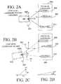
- FIG. 2Aillustrates a robot reference frame in the context of creating a record in a landmark database.
- FIG. 2Billustrates a landmark reference frame and a robot reference frame in the context of revisiting a landmark.
- FIG. 2Cillustrates the convention used to describe a ⁇ x and a ⁇ y calculation.
- FIG. 2Dillustrates the convention used to describe a ⁇ calculation.
- FIG. 3illustrates one embodiment of a system architecture for a VSLAM system.
- FIG. 4illustrates a SLAM graph representing landmark pose nodes and other pose nodes of a robot.
- FIG. 5illustrates various information associated with the nodes and edges of the SLAM graph.
- FIG. 6is a flowchart of a process useful in a visual front end for creating a new landmark.
- FIG. 7is a flowchart illustrating an overview of the front-end processing described in certain embodiments.
- FIG. 8is a flowchart elaborating on state 2702 of the flowchart of FIG. 7 , i.e. upon the landmark matching process implemented in certain embodiments.
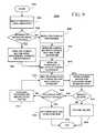
- FIG. 9is a flowchart elaborating on state 2705 of FIG. 7 , i.e. upon one embodiment of the landmark creation process.
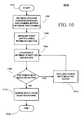
- FIG. 10is a flowchart elaborating on process 1616 of FIG. 9 , i.e. upon the process for estimating 3-dimensional structure and camera motion for landmark creation.
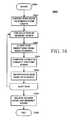
- FIG. 11is a flowchart illustrating an overview of the back-end processing described in certain embodiments.
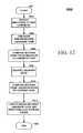
- FIG. 12is a flowchart elaborating on state 2602 of the flowchart of FIG. 11 , i.e. illustrating a process for integrating a landmark into a graph back-end.
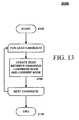
- FIG. 13is a flowchart elaborating on state 2606 of the flowchart of FIG. 11 , i.e. illustrating a process for integrating observations into a SLAM graph.
- FIG. 14illustrates the changing structure of a SLAM graph following certain of the operations described in FIGS. 15-17 .
- FIG. 15is a flowchart elaborating on state 2607 of the flowchart of FIG. 11 , i.e. reduction of the SLAM graph complexity.
- FIG. 16is a flowchart elaborating on state 2802 of the flowchart of FIG. 15 , i.e. node selection and removal.
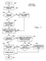
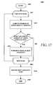
- FIG. 17is a flowchart elaborating on state 2302 of the flowchart of FIG. 16 , i.e. choosing a pose node to remove from the SLAM graph.
- FIG. 18is a flowchart elaborating on state 2804 of the flowchart of FIG. 15 , i.e. edge selection and removal.
- FIG. 19is a flowchart elaborating on state 2610 of the flowchart of FIG. 11 , i.e. one method for graph optimization.
- posethe position and orientation, such as the position and orientation of a robot, in some reference frame.
- robot posealso known as global robot pose: the position and orientation of a robot in a global reference frame.
- the robot posecan be specified by a two-dimensional position (x,y) and a heading ( ⁇ ).
- relative robot posethe position and orientation of a robot with respect to another reference frame, such as a landmark reference frame.
- global reference framea reference frame that is fixed to the environment.
- landmark reference framethe reference frame in which a landmark's 3-D structure is defined.
- 3-D structurethe 3-D coordinates of a set of 3-D features.
- a landmarkcomprises a collection of 3-dimensional (3-D) features and a unique identifier.
- 3-D featurean observable location, such as, for example, a portion of an object, with an associated 3-D coordinate in a reference frame and one or more associated 2-D features observable when viewing the location. It will be understood that a 3-D feature can be observed from one or more perspectives with varying 2-D features.
- 2-D featurea position in an image and a descriptor that relates to the pixel at the position or the pixels in some neighborhood around that position.
- physical landmarka collection consisting of one or more visually-identifiable 3-D features in the environment.
- landmark posethe pose of the landmark reference frame in the global reference frame.
- camera posea relative pose in the landmark reference frame based on the location of the visual sensor, which can be, for example, a camera.
- Embodiments of the inventionadvantageously use one or more visual sensors and one or more dead reckoning sensors to process Simultaneous Localization and Mapping (SLAM).
- SLAMSimultaneous Localization and Mapping
- VSLAMis advantageously used by a vehicle, such as a mobile robot, to autonomously generate and update a map.
- VSLAMis advantageously used by a portion of a vehicle, such as by an “arm” of a vehicle.
- the visual techniquesare economically practical in a wide range of applications and can be used in relatively dynamic environments, such as environments in which people move. Certain embodiments maintain the representation of SLAM information in a relatively computationally-efficient manner, thereby permitting the SLAM processes to be performed in software using relatively inexpensive microprocessor-based computer systems.
- a robotcan be embodied in a variety of forms.
- a robotmay be referred to by a different name, such as by a function that is performed by the robot.
- a robotmay be referred to as an automated sweeper or as an automated vacuum cleaner.
- a mobile robotcorresponds to a self-propelled object that can navigate in an autonomous or semi-autonomous manner.
- autonomous or semi-autonomous mobile robotsinclude, but are not limited to, mobile robots for use in automated floor cleaners, humanoid robots, robots for experimentation and lab use, robots for delivering supplies, robots for exploring confined or inaccessible spaces, robots for entertainment or play, and the like.
- the VSLAM techniques disclosed hereincan advantageously be applied to autonomous robots and to non-autonomous robots.
- the VSLAM techniquescan be used with a manually-driven vehicle, such as a remotely-controlled vehicle for bomb detection or other mobile electronic device.
- the VSLAM techniquescan be advantageously used in a remote-control application to assist an operator to navigate around an environment.
- a vehiclecan include various operational modes, such as a mode for manual control of the vehicle and another mode for an autonomous control of the vehicle.
- the vehiclecan be manually-driven during an initial mapping stage, and then later, the vehicle can be configured for autonomous control.
- the VSLAM techniquescan be used by a scout to create a map of the region.
- the scoutcan correspond to, for example, a person or another animal, such as a dog or a rat.
- the VSLAM used by the scoutcan be coupled to a video camera carried by the scout to observe the environment and to a dead reckoning device, such as an odometer, a pedometer, a GPS sensor, an inertial sensor, and the like, to measure displacement.
- the map generated by the scoutcan be stored and later used again by the scout or by another entity, such as by an autonomous robot. It will be understood that between the generation of the map by the scout and the use of the map by another entity, there can be additional processing to accommodate differences in visual sensors, differences in the installed height of the visual sensor, and the like.
- the mobile systemmay be interfaced with a robot, such as when a smart phone is inserted into a robot chassis.
- Robotscan be specified in a variety of configurations.
- a robot configurationtypically includes at least one dead reckoning sensor and at least one video sensor.
- Another name for dead reckoningis “ded” reckoning or deduced reckoning.
- An example of a dead reckoning sensoris a wheel odometer, where a sensor, such as an optical wheel encoder, measures the rotation of a wheel. The rotation of wheels can indicate distance traveled, and a difference in the rotation of wheels can indicate changes in heading.
- the robotcan compute course and distance traveled from a previous position and orientation (pose) and use this information to estimate a current position and orientation (pose). While relatively accurate over relatively short distances, dead reckoning sensing is prone to drift over time.
- a dead reckoning sensorcan correspond to either distance, to velocity, or to acceleration and can be converted as applicable.
- Other forms of dead reckoningcan include a pedometer (for walking robots), measurements from an inertial measurement unit, optical sensors such as those used in optical mouse devices, and the like.
- drift errorscan accumulate in dead reckoning measurements.
- examples of sources of driftinclude calibration errors, wheel slippage, and the like. These sources of drift can affect both the distance computations and the heading computations.
- Embodiments of the inventionadvantageously use a visual sensor to recognize landmarks on a visual basis. These observations of visual landmarks can advantageously provide a global indication of position and can be used to correct for drift in the dead reckoning sensors.
- SLAMsimultaneous localization and mapping
- embodiments of the inventioncan use data from visual sensors and from dead reckoning sensors to provide simultaneous localization and mapping (SLAM) with advantageously little or no additional cost.
- FIG. 1illustrates an example of a mobile robot 100 in which a VSLAM system can be incorporated.
- the illustrated robot 100includes a visual sensor 104 , which is used to visually recognize landmarks such that a SLAM module can determine global position.
- a broad variety of visual sensorscan be used for the visual sensor 104 .
- the visual sensor 104can correspond to a digital camera with a CCD imager, a CMOS imager, an infrared imager, and the like.
- the visual sensor 104can include normal lenses or special lenses, such as wide-angle lenses, fish-eye lenses, omni-directional lenses, and the like.
- the lenscan include reflective surfaces, such as planar, parabolic, or conical mirrors, which can be used to provide a relatively large field of view or multiple viewpoints.
- the visual sensor 104can correspond to a single camera or to multiple cameras.
- the VSLAM systemis advantageously configured to operate with a single camera, which advantageously reduces cost when compared to multiple cameras.
- the motors 110 , 112 of the illustrated robot 100are coupled to wheels 114 , 116 to provide locomotion for the robot 100 .
- wheelscan use legs, tracks, rollers, propellers, and the like, to move around.
- information regarding the rotation of the wheelsalso known as odometry, is provided as an input to a control 108 .
- Image data 106 from the visual sensor 104is also provided as an input to the control 108 for the robot 100 .
- the VSLAM systemis embodied within the control 108 .
- the control 108is coupled to motors 110 , 112 to control the movement of the robot 100 .
- a power source for the robot 100such as a battery, is not shown in FIG. 1 .
- the control 108can provide control signals to the motors 110 , 112 that control the movement of the robot 100 .
- the control 108can provide control signals to instruct the robot to move forward, to stop, to move backward, to turn, to rotate about a vertical axis, and the like.
- this rotationis referred to as “yaw.”
- the control 108can include hardware, such as microprocessors, memory, etc., can include firmware, can include software, can include network communication equipment, and the like.
- the control 108uses dedicated hardware, such as single-board computers, application specific integrated circuits (ASICs), field programmable gate arrays (FPGAs), and the like.
- ASICsapplication specific integrated circuits
- FPGAsfield programmable gate arrays
- the control 108is implemented by interfacing to a general-purpose computer, such as to a laptop computer, and by software executing in the computer.
- a laptop computer with an Intel® Pentium® 4 processor with a 2.4 GHz clock speedcan process landmark generation processes in about 1 second and can process visual measurements in about half a second. It will be understood that the processing time can depend on parameters such as image resolution, frame rates, bus speeds, and the like.
- the softwarecan include instructions that are embodied in a tangible medium, such as a hard disk or an optical disk.
- Data processing for the robot 100can be performed entirely within the robot 100 such that the robot 100 is autonomous, or the data processing can be performed partially outside the robot 100 .
- the control 108can be configured to relay data to another computer, via a network such as a wireless network, where a portion of the data processing takes place.
- the robotcan observe physical landmarks.
- these physical landmarkscan be related to landmarks created and stored in a database.
- the VSLAM techniquesdo not require artificial navigational beacons to be placed in the environment. Rather, VSLAM techniques can conveniently be used in unaltered and unmodified environments.
- the VSLAM techniquescan utilize features from the beacons and/or the surrounding environment as landmarks. For example, in a landmarks database, where a landmark can correspond to a collection of 3-D features and the corresponding 2-D features from which the 3-D features are computed.
- a physical landmarkcan correspond to one or more physical objects, such as, for example, an object mounted to a wall and a portion of the wall. These physical landmarks are used to estimate global position such that drift in dead reckoning measurements can later be corrected or compensated. It should be noted that a physical landmark will typically be arranged in a particular location and orientation in the global reference frame, and that the observing robot will be at a different location and orientation. In certain embodiments, the locations of the features of the physical landmark are referenced relative to the landmark reference frame. Then, the pose of the landmark itself is referenced to the global reference frame.
- the VSLAM systemcan also be used in a variety of devices such that the robot pose can also correspond to a device pose.
- the orientation ( ⁇ ) of the robot as it observes the physical landmark and creates the landmark in the databaseis indicated with an arrow.
- the initial estimate of the pose of the “landmark” that is referenced in the global reference framecorresponds to the pose of the robot when creating the landmark.
- the set of 3-D features and their corresponding 2-D features that visually identify the landmarkare stored.
- the 2-D featurescorrespond to SIFT features.
- SIFTThe concept of SIFT has been extensively described in the literature. See David G. Lowe, Local Feature View Clustering for 3 D Object Recognition , Proceedings of the IEEE Conference on Computer Vision and Pattern Recognition, Kauai, Hi. (December 2001). One will readily recognize variations and alternatives to SIFT, such as SURF, BRIEF, etc.
- dead reckoning measurementssuch as those obtained from odometry readings
- these dead reckoning measurementscan drift or accumulate errors over distance and/or time such that a position calculated after a relatively long period of time can vary significantly from a position that was initially calculated even when the errors in the dead reckoning measurements are relatively small.
- the robotcan make relatively many traversals over an environment, thereby accumulating errors in drift.
- the VSLAM techniquescan wholly or partially compensate for the drift in the dead reckoning measurements such that even after a robot has traveled over relatively large distances, the global position of the robot can be maintained with relatively high accuracy.
- the VSLAM techniquesmaintain the accuracy of the global robot pose estimate to exceed the accuracy of the visual measurements even after the robot has traversed relatively long distances.
- the visual sensor usedwas a relatively simple and inexpensive color camera with a resolution of 640 ⁇ 480, and the accuracy of the visual measurements was maintained to about 10 centimeters (cm). It will be understood that other visual sensors, such as grayscale cameras and infrared cameras, can also be used.
- a trinoculor camerasuch as the DigiclopsTM camera available from Point Grey Research Inc., of Vancouver, British Columbia, Canada may be used.
- camera systemsthat provide a stereoscopic view, such as binocular or trinocular camera systems, can be used to identify 3-D features of a landmark and to estimate displacements to the 3-D features in a relatively fast and efficient manner.
- such camerasare produced in relatively low volumes and can be relatively expensive relative to single visual sensor cameras due to the extra components and to the relative lack of economies of scale.
- FIGS. 2A and 2Billustrate a robot 502 and a corresponding robot reference frame 520 .
- the robot reference frame 520is used by the visual localization portion of a VSLAM system.
- the zero vector for the robot reference frame 520moves with the robot 502 .
- the robot reference frame 520is a relative reference frame, as opposed to a global reference frame that has a globally-fixed zero vector.
- the zero vector for the robot reference frame 520can be located approximately at the camera of the robot 502 and is illustrated in FIG. 2A by a pose “A” 522 and in FIG. 2B by a pose “B” 524 .
- FIG. 2Aillustrates the robot reference frame 520 in the context of “creating” or recognizing a new landmark, i.e., creating an entry in a database for a freshly observed landmark.
- FIG. 2Billustrates the robot reference frame 520 in the context of revisiting a previously observed and recorded landmark.
- the robot reference frame 520moves with the robot 502 such that the pose “A” 522 corresponding to the pose of the robot, with respect to the global reference frame, at the time when the landmark was created, and the pose “B” 524 corresponding to the pose of the robot, with respect to the global reference frame, at the time when the landmark was revisited can be different as illustrated in FIG. 2B .
- a physical landmark 504is identified by its 3-D features.
- 3-D featuresare extracted by triangulating 2-dimensional (2-D) features by solving the structure and motion problem using the trifocal tensor method.
- the 2-D featuresare SIFT features.
- SIFT featuresA discussion of SIFT features can be found in Lowe, id. See Olivier Faugeras and Quang-Tuan Luong, The Geometry of Multiple Images , MIT Press (2001) for a discussion of the trifocal tensor method.
- the physical landmark 504can be characterized by relatively many 3-D features and that the physical landmark 504 can correspond to one or more physical objects or to a portion of physical object.
- the physical landmark 504 illustrated in FIG. 2Ais drawn with 3 3-D features: a first feature 506 , a second feature 508 , and a third feature 510 .
- the visual front enddetermines the displacements or positions from the robot 502 to the respective features.
- the robot 502can reference displacements to visual features using the current position of the robot reference frame 520 as an initial estimate of a landmark reference frame. For example, in the example illustrated in FIG.
- arrows r 1 , r 2 , and r 3represent 3-dimensional displacements, such as displacements in x, y, and z dimensions between the robot 502 and the first feature 506 , the second feature 508 , and the third feature 510 , respectively.
- these x, y, and z displacementsare relative to the robot reference frame of the robot 502 and not to the global reference frame.
- the x, y, and z displacementscorrespond to relative displacements in the fore-aft dimension, in the left-right dimension, and in the up-down dimension, respectively.
- the 2-D image coordinates or locations for the 3-D featuresare also stored.
- the 2-D image coordinatescorrespond to one or more pixel locations that correspond to the 3-D features. It will be understood that 3-D features will typically occupy more than merely a single point in space.
- the displacements from the robot 502 to the featuresare referenced to the first image in a three-image set.
- any identifiable reference framecan be used as the reference.
- the other images in the image setcan also be used as the reference, so long as the image used as the reference is consistently selected.
- an identifiable reference frame that does not correspond to any particular imagecan also be used.
- the pose of the robot corresponding to the first image in the three-image setis used as the local reference frame for the particular landmark, i.e., the landmark reference frame.
- the Visual Front End 602when a new physical landmark is encountered, stores (i) the 3-D coordinates of the 3-D features in the local reference frame for the landmark in a database, such as a landmark database 606 of FIG. 3 and (ii) the 2-D features for a selected image, such as the 2-D features of the first image, corresponding to the 3-D features.
- the SLAM module 604when the new physical landmark is encountered and processed by the Visual Front End 602 , the SLAM module 604 correspondingly “creates” a landmark by storing an initial estimate of the landmark pose, such as the global robot pose when the landmark was created, computed from the change in pose as provided by the dead reckoning data for each particle from the last pose of the robot for the corresponding particle.
- FIG. 2Billustrates an example of the robot 502 revisiting the physical landmark 504 earlier observed, termed “new view.”
- the robot 502is displaced from the original pose “A,” which corresponds to the “landmark reference frame,” to a new pose “B.”
- the robot reference framealso moves with the robot 502 .
- the robot 502again observes the first feature 506 , the second feature 508 , and the third feature 510 . It will be understood that as the robot 502 moves about, some of the features of a physical landmark may not be observable in all locations.
- the Visual Front End 602 of the robot 502computes the relative pose, i.e., the difference between new pose “B” and pose “A,” as illustrated in FIGS.
- the Visual Front End 602computes the relative pose of the robot with respect to the stored landmark reference frame illustrated as “A” by finding the relative pose of the robot that minimizes the projection error from the 3-D features onto the 2-D coordinates of the first feature 506 , the second feature 508 , and the third feature 510 .
- Dashed lines between the robot 502 and the features 506 , 508 , 510represent the projection of the features 506 , 508 , 510 onto an image plane, which is illustrated by a line 530 in the top view of FIG. 2B .
- the image plane for a visual sensorsuch as a camera
- the line 530approximately represents the field of view of the camera for the projection of the points and does not indicate any particular distance from the camera.
- the Visual Front End 602can estimate the relative pose by, for example, minimizing projection error.
- the relative posereveals a change in pose from (i) the pose when the landmark was created and stored in the database to (ii) the pose when the physical landmark was re-observed.
- a relative posecan be represented in a variety of coordinate forms.
- the translational component of the relative pose along the floorcan be represented by Cartesian coordinates (x,y).
- polar coordinates ( ⁇ , ⁇ )can also be used.
- 2Dgraphically illustrate the relative pose also known as “camera pose” components of ⁇ x, ⁇ y, and ⁇ . While the term “camera pose” includes the word “camera,” it will be understood that visual sensors other than cameras can also be used.
- the relative posecan also include a change in vertical dimension, roll, and pitch, which can be the result of uneven floor surfaces, robot and/or camera movement in these dimensions, misidentified landmarks, changes in the physical landmarks in the environment, and the like. In one embodiment, these additional dimensions are advantageously used to test the validity of the identified landmark.
- the Cartesian-coordinate relative poseis used between a visual front-end and a SLAM module when re-encountering landmarks, and a polar-coordinate “delta pose” is used in the SLAM module when computing change in pose between points measured by dead reckoning data.
- the pose of the robot according to dead reckoning sensor data as the robot travels in its environmentis stored with a corresponding timestamp in a matrix. Retrieval of poses according to two points in time permits change in heading, direction traveled, and distance traveled to be computed between the two points in time.
- FIG. 3illustrates one embodiment of a system architecture for a VSLAM system 600 .
- the VSLAM system 600can be implemented in a variety of ways, such as by dedicated hardware, by software executed by a microprocessor, or by a combination of both dedicated hardware and software.
- Inputs to the VSLAM system 600include raw pose data 610 from one or more dead reckoning sensors 614 and also include visual data 612 from one or more cameras or other visual sensors 616 .
- a dead reckoning sensor 614such as an optical wheel encoder, can communicate with the VSLAM system 600 via a dead reckoning interface 618 , such as via a driver or via a hardware abstraction layer.
- the raw pose data 610can correspond to distance traveled, to velocity, to acceleration, and the like, and can depend on the type of dead reckoning sensor used.
- Outputs from the VS LAM system 600can include one or more poses and maps 620 .
- the raw pose data 610 and the visual data 612are provided as inputs to the Visual Front End 602 .
- the Visual Front End 602can perform a variety of functions, such as identify landmarks, identify 3-D features for landmarks, calculate delta pose, and the like. Examples of processes that can be performed by the Visual Front End 602 will be described in greater detail later in connection with FIG. 4 .
- the Visual Front End 602can use the raw pose data 610 to determine the approximate distance traveled between the images in the visual data 612 , which are then used in computations to measure the displacements to the features.
- corresponding records or entriescan be added to the landmark database 606 .
- Newly recognized landmarkscan also be indicated to the SLAM module 604 . For example, a “new landmark” flag can be activated, and a “new landmark” identifier or tag can be provided to the SLAM module such that the appropriate records in a SLAM database 608 and the landmark database 606 can be matched.
- the Visual Front End 602can provide the SLAM module 604 or an optional Pre-Filter module 622 with one or more identifiers or tags to indicate the one or more landmarks encountered, relative pose information, such as relative pose information ( ⁇ x, ⁇ y, and ⁇ ), and data reliability measures as applicable.
- the optional Pre-Filter module 622analyzes the data reliability measures provided by the Visual Front End 602 .
- the data reliability measurescan be used as an indication of the reliability of the identification of the physical landmark by the Visual Front End 602 .
- the Pre-Filter module 622can advantageously be used to identify a landmark measurement identified by the Visual Front End 602 , which may have been inaccurately identified and can correspond to an outlier with respect to other landmarks in a map.
- the Pre-Filter module 622identifies a potentially inaccurate visual measurement
- the Pre-Filter module 622does not pass the identified visual landmark data onto the SLAM module 604 such that the VSLAM system 600 effectively ignores the potentially inaccurate landmark measurement.
- Pre-filtering of data to the SLAM module 604can advantageously enhance the robustness and accuracy of one or more poses (position and orientation) and maps 620 estimated by the SLAM module 604 .
- the SLAM module 604maintains one or more poses and maps 620 .
- the SLAM module 604maintains multiple particles or hypotheses, and each particle is associated with a pose and a map.
- the SLAM module 604receives the raw pose data 610 from the dead reckoning interface 618 . It will be understood that the nature of the raw pose data 610 can vary according to the type of dead reckoning sensor 614 and the type of output specified by the dead reckoning interface 618 . Examples of the raw pose data 610 can include distance measurements, velocity measurements, and acceleration measurements.
- the dead reckoning datais used by the SLAM module 604 to estimate course and distance traveled from a prior pose. It will be understood that where multiple hypotheses are used by the SLAM module 604 , that the dead reckoning data is used to estimate course and distance traveled from relatively many prior poses.
- Other inputs to the SLAM module 604include visual localization data from the Visual Front End 602 and/or the optional Pre-Filter module 622 .
- visual localization datafrom the Visual Front End 602 and/or the optional Pre-Filter module 622 .
- the robotobserves visual landmarks.
- the SLAM module 604can store the robot's global reference frame location for the particles in the SLAM database 608 .
- the robot's posecan be estimated from a previous location and the course and distance traveled from a last known pose.
- the SLAM module 604When a previously created landmark is observed, the SLAM module 604 is provided with a new estimate of relative pose information, such as ⁇ x, ⁇ y, and ⁇ to the observed landmark, from the Visual Front End 602 or the optional Pre-Filter module 622 .
- the SLAM module 604uses the change in pose information to update the one or more poses and maps 620 maintained. Accordingly, the visually observed landmarks can advantageously compensate for drift in dead reckoning measurements.
- a landmarkis associated with a landmark tag or identifier I, a landmark pose estimate S, and an uncertainty measure, such as, for example, a covariance matrix C.
- Information describing the visual characteristics or image of the landmarkcan be stored in a collection of data associated with the Visual Front End 602 , such as in the landmark database 606 .
- a cross reference or database record identifiercan be used to identify the landmark tag I.
- the landmark pose Scorresponds to the pose of the robot itself when the robot “creates” the landmark and adds the landmark to the map.
- the landmark pose Scan also be updated when the robot re-observes the landmark.
- the landmark pose Scorresponds to a 3 ⁇ 1 column vector with the contents of an x-dimension x for global reference, a y-dimension y for global reference, and a robot heading ⁇ relative to the global reference frame.
- the hypothetical pose and the corresponding mapcan advantageously vary among the particles of a multi-particle or multiple hypothesis SLAM system.
- a covariance matrix Crepresents the uncertainty of the landmark pose S.
- the symbol C m kwill be used herein to denote the covariance matrix associated with landmark k for particle m.
- the covariance matrix C m kis updated with a Kalman filter.
- a databasecan be implemented on an addressable storage medium and can be implemented using a variety of different types of addressable storage mediums.
- the landmark database 606 and/or the SLAM database 608can be entirely contained in a single device or can be spread over several devices, computers, or servers in a network.
- the landmark database 606 and/or SLAM database 608can be implemented in such devices as memory chips, hard drives, optical drives, and the like.
- the databasemay also be, by way of example, an object-oriented database, a hierarchical database, a lightweight directory access protocol (LDAP) directory, an object-oriented-relational database, and the like.
- the databasesmay conform to any database standard, or may even conform to a non-standard, private specification.
- the databasecan also be implemented utilizing any number of commercially available database products such as, by way of example, Oracle® from Oracle Corporation, SQL Server and Access from Microsoft Corporation, Sybase® from Sybase, Incorporated and the like.
- RDBMSrelational database management system
- data within the tableis stored within fields, which are arranged into columns and rows.
- Each fieldcontains one item of information.
- Each column within a tableis identified by its column name and contains one type of information, such as a value for a SIFT feature.
- the size of the databases holding the various maps for the particlescan grow over time as landmarks are accumulated in the maps.
- One embodiment of the inventionalso include techniques for managing the databases.
- the landmark database 606 and the SLAM database 608can be managed to provide efficient performance of VSLAM processing in a diverse variety of settings and to manage the amount of memory used in VSLAM processing.
- One way to efficiently manage the databasesis to remove landmarks from the databases that are perceived to be no longer present in the environment or can otherwise be considered unreliable, bad, or in any other way undesired.
- the assessment that a physical landmark has disappeared from the environment such that the corresponding landmark should be removed from the databasescan be based on repeatedly not observing the physical landmark at or near poses where it is expected to be observed.
- measurements that repetitively correspond to outlierscan also be considered to be unreliable and can be removed from the databases.
- a landmarkcan be considered to be unreliable or bad if measurements of the landmark over time have been repeatedly inconsistent or otherwise indicated as unreliable.
- An example of a range for repeatedly inconsistent measurementsis about 5 to 10 inconsistent measurements. Other appropriate values will be readily determined by one of ordinary skill in the art.
- a measurement for a landmarkis inconsistent if the measurement suggests that the robot is located relatively far away from where a relatively large proportion of the particles, such as about 90%, the SLAM subsystem predicts the robot to be.
- the robotis determined to be located relatively far away when the SLAM prediction prior to incorporation of the new visual measurement into an estimate falls outside a 95% confidence ellipse.
- the 95% confidence ellipsehas (i) the visual measurement estimate of robot pose as its mean, and (ii) C sensor as its covariance matrix.
- the robotcan be determined to be located relatively far away when the difference between the pose estimated by SLAM and the pose estimated by the visual measurement exceed a predetermined threshold.
- An example of an appropriate value for a predetermined threshold in an indoor environmentis about 2 meters. Other values will be readily determined by one of ordinary skill in the art.
- landmarkscan be considered undesirable when, for example, it is determined that the density of landmarks in some parts of the map is relatively high, such as about 5-10 landmarks per square meter for an indoor environment. It will be understood that the density of landmarks can vary considerably from one environment to another and that correspondingly, appropriate thresholds for “high” density will also vary and will be readily determined by the skilled practitioner. By selectively removing some of the landmarks in a too dense portion of the map, memory can be freed for other tasks.
- a memory management techniquecan be used when the landmark database has grown to a relatively large size.
- a mass storage devicesuch as a hard disk is relatively slow compared to a solid-state memory device, such as random access memory (RAM).
- RAMrandom access memory
- a mass-storage devicetypically has much more storage capacity than a solid-state memory device.
- a solid-state memory devicesuch as, for example, a flash memory or an EEPROM device, can be used to store a landmark database in a non-volatile manner. Memory usage can be efficiently managed by maintaining only a relatively small fraction of the total landmark database in the relatively fast memory, such as the RAM, at a time.
- a few initial landmark measurements and comparisons with the landmark databasecan typically reveal approximately where the robot is likely to be operating in a mapped environment. For example, an entire house, office, or hospital floor can be mapped as the environment; and after a few initial measurements, the VSLAM system 600 can determine that the robot is in a particular room in a house, on the first floor of an office, in a particular wing of a hospital, and the like.
- the VSLAM system 600can then maintain a relatively small subset of the database in RAM that contains the relevant portion of the database, and other previously used memory resources can be released back to the system. Should, for example, a relatively long period of time transpire without successful matches with the loaded subset of the database, the entire map can again be loaded temporarily to determine if the robot has been moved or has moved to another part of the environment. For example, the robot may have traveled autonomously or may have been picked up and moved to a new location.
- the subset of the map that is maintained in relatively fast memorysuch as RAM can at least temporarily correspond to a randomly selected subset of the plurality of landmarks from the map.
- the subset of the map that is maintained in relatively fast memorycan at least temporarily correspond to a subset that is selected such that the density of landmarks remaining in the subset is relatively uniformly distributed throughout the map.
- the VS LAM systemadvantageously discontinues adding new landmarks to the database.
- the VSLAM systemdiscontinues landmark creation in a portion of an environment or in the entire environment at least partly in response to a determination that the landmark density has exceeded a predetermined threshold, such as 5-10 landmarks per square meter. For example, when a database for an environment exhibits relatively high landmark density in one portion of the environment and a relatively low landmark density in another portion of the environment, the addition of new landmarks to the database can be disabled for the portion of the environment corresponding to the relatively high landmark density in the database, and the addition of new landmarks can be enabled for portions of the environment corresponding to the relatively low landmark density.
- the VSLAM systemdiscontinues adding new landmarks to the database at least partly in response to a landmark creation decay rate, i.e., a determination that over a period of time, fewer and fewer new landmarks are being identified.
- the measurement of the landmark creation decay ratecan be applied to parts of an environment or to the entire environment. For example, in a relatively static environment under relatively constant lighting conditions, the rate at which landmarks are created will typically be highest in the beginning, before many landmarks have been created. After the area has been partially mapped by the creation of landmarks, i.e., the addition of landmarks to the database, the visual front end less frequently attempts to create landmarks.
- a creation ratecorresponds to the number of landmarks created per meter of travel.
- a thresholdwhich can correspond to for example, (i) a predetermined value such as 1 landmark every 10 meters, or can correspond to (ii) a percentage of the initial creation rate such as 5% of the rate (per unit of distance traveled) obtained during the first passage through the relevant part of the environment, then landmark creation can be temporarily discontinued in that part of the environment.
- the VSLAM systemdiscontinues adding new landmarks to the database for all or part of the environment at least partly in response to a ratio of visual measurements to landmarks created.
- the discontinuing of adding landmarkscan also be triggered at least partly in response to elapsed time, such as after 30 minutes of mapping, or at least partly in response to memory usage, such as when 75% of the memory has been used for the landmark database.
- FIG. 4provides an example of how certain of the present embodiments represent landmarks and other poses of the robot in a graph structure, referred to herein as a SLAM graph.
- pose nodesmay be classified as either “normal” pose nodes 1802 or “landmark” pose nodes 1804 .
- Landmark pose nodes 1804identify a pose node with a landmark associated with the node.
- “Normal” pose nodes 1802in contrast, indicate only the robot's pose.
- a plurality of pose nodes 1802 , 1804are connected by a plurality of edges 1806 . Adjusting the SLAM graph in real-time to more optimally represent the past observations will facilitate more efficient navigation.
- Each pose node 1802 in the SLAM graphencodes the estimated pose of the robot at a particular time step of operation.
- Each oriented edge 1806encodes an estimate of the transformation between the coordinate frame of the source graph node and the destination graph node.
- the SLAM graphmay be constructed and refined incrementally during operation, that is, in real-time.
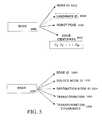
- FIG. 5shows the information associated with nodes and edges in the SLAM graph in certain embodiments in greater detail.
- Each edge 1810includes a unique identifier 1820 , and the identifier of its source node 1822 and its destination node 1824 .
- the transformation from source to destinationis encoded as a Gaussian random vector which is represented by its mean 1826 and covariance 1828 over the coordinate transformation parameters.
- the a distribution different from Gaussiancould be used and it can be represented by sample particles or in a parametric form.
- a deterministic formulationcan be used where only the mean value is stored in the edge data structure. The contents of a pose or landmark node are shown in further detail in 1808 .
- Each nodehas a unique identifier 1812 , a robot pose estimate 1816 , and a list of edge identifiers 1818 that enumerates the edges incident to the node in the SLAM graph.
- the nodeis a landmark node, it may also encode the unique identifier 1814 of the landmark associated with the node.
- pose estimatedcan be represented as a random variable or a deterministic parameter. In a case of a random variable, either a parametric or a numerical sample could be used to represent the distribution. In one embodiment, a Gaussian distribution is used and the parameters are the mean vector and the covariance matrix. Nodes and edges may be accessed via each of the unique identifiers 1812 , 1820 .
- the structures depicted in FIG. 5are merely provided by way of example and one will readily recognize a plurality of alternative representations.
- FIG. 6is a flowchart generally illustrating a process that can be used in a visual front end when recognizing a new physical landmark in the environment and creating a corresponding landmark in one or more maps in a database.
- the act of creating a new landmarkmay also be referred to as “generating” a landmark.
- the illustrated processcan be modified in a variety of ways without departing from the spirit and scope of the invention. For example, in another embodiment, various portions of the illustrated process can be combined, can be rearranged in an alternate sequence, can be removed, and the like.
- the processcan be performed in a variety of ways, such as by software executing in a general-purpose computer, by firmware executed by a microprocessor, by dedicated hardware, and the like.
- the processbegins at a state 1002 , where the process retrieves a group of at least 2 images for analysis.
- the imagescan be provided by a visual sensor with multiple images, such as a binocular or trinocular camera, or by a visual sensor with a single imager, such as from a single camera.
- the processcan select images that are appropriately spaced apart.
- the robotis equipped with a single forward-looking camera and travels forward to take related images.
- the visual sensorcan correspond to a generally upward-pointing camera, to a sideways-looking camera, or to positions between forward looking, upward, and/or sideways.
- three imagesare selected at a separation distance of at least about 10 centimeters (cm) apart.
- an appropriate distance for the separation distancecan vary in a broad range depending on the environment. For example, where the operating environment corresponds to a relatively expansive environment, such as to an outdoor environment, the appropriate distance for separation between images can be higher in order to gain perspective on the features.
- the separation distancecan be adaptively varied in response to an estimate of the proximity of obstacles that can obstruct the motion of the robot.
- the robotis equipped with a single forward-looking camera, the robot moves in an approximately straight line in the forward direction while taking the images. Although some turning can be tolerated while the robot is taking images, the turning should not be so excessive such that the features of the landmarks are no longer in the view of the camera.
- the processadvances from the state 1002 to an optional state 1004 .
- the state 1004 and a decision block 1006can be optional depending on the configuration of the robot. Where the robot is equipped with a visual sensor with multiple imagers, such as a trinocular camera, the state 1004 and the decision block 1006 can be skipped, and the spacing between the visual sensors can be retrieved from a stored parameter in memory. When skipped, the process advances from the state 1002 to a state 1010 .
- the processretrieves the actual distances between images in the state 1004 and checks the amount of movement in the decision block 1006 . In one embodiment, these distances are determined by monitoring the dead reckoning data corresponding to the times at which the images were taken. The process advances from the state 1004 to the decision block 1006 .
- the processtests the distance traveled between images, termed “baseline.” For example, the amount of baseline between images can be compared to a predetermined value. It will be understood that the predetermined value can vary in a very broad range. In an indoor environment, such as the interior of a home or apartment, an appropriate value can be about 10 centimeters for the predetermined value. Of course, the appropriate value can depend on the environment, and other appropriate values will be readily determined by one of ordinary skill in the art.
- the processproceeds to a state 1008 , and the process does not create a landmark. Otherwise, the process proceeds from the decision block to the state 1010 .
- the processanalyzes the selected images to identify 2-D features that are common to the images in the group.
- the number of features that are observablewill vary according to the environment.
- SIFT featuresare one example of such 2-D features. See, for example, David G. Lowe, Local Feature View Clustering for 3 D Object Recognition Proceedings of the IEEE Conference on Computer Vision and Pattern Recognition, Kauai, Hi. (December 2001).
- other information used in the calculation of the featurescan include intrinsic camera calibration parameters and extrinsic camera parameters. Examples of intrinsic camera calibration parameters include optical center, distortion parameters, and focal length. Examples of extrinsic camera calibration parameters include a camera-rigid transformation between the camera reference frame and the local reference frame.
- the processadvances from the state 1010 to a decision block 1012 .
- the processdetermines whether enough features have been identified that are common to the images in the group, e.g., the three images, for reliable identification of the landmark.
- the processdetermines that fewer than a predetermined number of features are common to the images in the group, the process can determine that there are not enough features detected to reliably identify the landmark in the future. In this case, the process can proceed from the decision block 1012 to the state 1008 , and the process does not “create” a landmark.
- an appropriate value for the predetermined number of featurescan vary in a very broad range and can depend on the method used to identify visual features. In one embodiment, the predetermined number of features is higher for the decision block 1012 for landmark creation than a predetermined value used to compare an image to an already stored landmark.
- VSLAM system 600can be configured to permit predetermined values to be user configurable. The process proceeds from the decision block 1012 to a state 1014 when enough features common to the images in the group have been identified.
- the processcomputes 3-D local reference frame positions or displacements to the common features identified in the state 1010 .
- the 3-D local reference frame positionscorrespond to the approximate 3-D position (x, y, z) of a feature relative to the visual sensor of the robot. Where multiple images are taken from a single visual sensor as the robot moves, the 3-D local reference frame positions can be relative to the position of the robot when the robot took one of the images in the group, such as the first image in the group.
- the computations for the 3-D positionsare resolved by solving the structure and motion problem using the trifocal tensor method. It will be understood that the features can occupy a space larger than a point, such that the correspond 3-D positions can be relatively approximate.
- the processadvances from the state 1014 to a decision block 1016 .
- the processdetermines whether there have been enough 3-D local reference frame positions for features resolved in the state 1014 for the landmark to be reliably recognized. It will be understood that occasionally, the process may not find a solution to the 3-D local reference frame positions for a particular feature such that the number of 3-D features with corresponding displacement information can be different than the number of such initially-detected features. For example, in the decision block 1016 , the process can compare a count of the 3-D local reference frame positions resolved for features of a landmark to a predetermined number. In one embodiment, where SIFT features are used, the process determines that a landmark has a sufficient number of features with 3-D local reference frame positions resolved for relatively reliable recognition when there have been 10 or more such features resolved.
- the processproceeds from the decision block 1016 to a state 1018 when the landmark has been determined to be reliably recognized. Otherwise, the process proceeds from the decision block 1016 to the state 1008 , and the process does not “create” a landmark.
- the processidentifiably stores the features, the 3-D positions, and, optionally, the approximate 2-D image locations corresponding to the features for the image that is used as the reference.
- the 3-D position and the 2-D image location for a featurecan be stored in a record in a feature table.
- each landmark that is createdshould have a unique reference, such as a unique numbered identifier, and that each feature of a reference should also be identifiable, such as by a combination of the reference for the landmark, e.g., Landmark ID, and the reference for the feature, e.g., Feature ID.
- the processadvances from the state 1018 to a state 1020 .
- the processprovides an indication that a new landmark has been created to other processes, such as processes related to the SLAM portion of VSLAM.
- the indicationcan be provided as a parameter or flag in a software call, a hardware or a software interrupt, and the like.
- the indicationcan also be accompanied by the landmark identifier for the newly created landmark.
- Present embodimentsdisclose various improvements to the front-end and to the back-end of a SLAM-based mobile platform navigation system.
- the “front-end”refers to operations involved in generating landmarks, or recognizing landmarks in the graph
- “back-end”refers to operations concerning maintenance and upkeep of the SLAM graph.
- the division between “front-end” and “back-end” operationsis merely for conceptual convenience and one will readily recognize that certain operations may occur across this artificial division.
- present embodimentsdisclose a novel feature matching methodology wherein a global database is searched in conjunction with a local database of features. These embodiments are particularly discussed in relation to FIG. 8 .
- certain embodimentsdisclose a robust matching and estimation landmark creation process. These embodiments are particularly discussed in relation to FIG. 10 .
- certain embodimentscontemplate methods for improved optimization and management of the SLAM graph so as to improve memory usage and operational efficiency of the SLAM-based system. These embodiments are particularly discussed in relation to FIGS. 15-18 .
- a “mobile system”is a broad term and is to be given its ordinary and customary meaning to a person of ordinary skill in the art (i.e., it is not to be limited to a special or customized meaning) and includes, without limitation, any electronic system which may be moved, such as a robot, handheld electronic device, accessory to a vehicle and the like. Such a system may move under its own control, as in the example of a robot, while other systems may be moved by a user, such as in the example of a handheld device.
- a “trajectory”is a broad term and is to be given its ordinary and customary meaning to a person of ordinary skill in the art (i.e., it is not to be limited to a special or customized meaning) and includes, without limitation, any path upon which an object is to travel. For example, a robot may use a trajectory as the path between two waypoints across a terrain.
- a “pose node”is a broad term and is to be given its ordinary and customary meaning to a person of ordinary skill in the art (i.e., it is not to be limited to a special or customized meaning) and includes, without limitation, any data structure sufficient to store pose information for a mobile system.
- a “landmark node”will be understood as a pose node which is designated, either by an internal identifier or an external identifier, as comprising information related to a landmark.
- a “landmark”is a broad term and is to be given its ordinary and customary meaning to a person of ordinary skill in the art (i.e., it is not to be limited to a special or customized meaning) and includes, without limitation, any object, feature, or aspect found in a terrain which a system may subsequently identify.
- a “threshold”is a broad term and is to be given its ordinary and customary meaning to a person of ordinary skill in the art (i.e., it is not to be limited to a special or customized meaning) and includes, without limitation, any numerical value or condition which may be used as a basis for determining whether to perform an action.
- “identifying a pose node”is a broad term and is to be given its ordinary and customary meaning to a person of ordinary skill in the art (i.e., it is not to be limited to a special or customized meaning) and includes, without limitation, any operation used to select a pose node from a plurality of pose nodes.
- removing a pose nodeis a broad term and is to be given its ordinary and customary meaning to a person of ordinary skill in the art (i.e., it is not to be limited to a special or customized meaning) and includes, without limitation, any operation which modifies a graph so that the graph no longer references a pose node, or which initiates one or more operations so that the graph will no longer reference a pose node.
- “inserting a pose node”is a broad term and is to be given its ordinary and customary meaning to a person of ordinary skill in the art (i.e., it is not to be limited to a special or customized meaning) and includes, without limitation, any operation which modifies a graph so that the graph references the pose node, or which initiates one or more operations which will result in the graph referencing the pose node.
- “camera”is a broad term and is to be given its ordinary and customary meaning to a person of ordinary skill in the art (i.e., it is not to be limited to a special or customized meaning) and includes, without limitation, any device capable of capturing an image.
- “navigation system”is a broad term and is to be given its ordinary and customary meaning to a person of ordinary skill in the art (i.e., it is not to be limited to a special or customized meaning) and includes, without limitation, any software, hardware, or firmware module configured to perform certain of the operations disclosed herein.
- a laptop, or any mobile computer systemcomprising software instructions to maintain a SLAM graph and to perform one or more of the operations depicted in FIGS. 16-18 would comprise a navigation system.
- “planner”is a broad term and is to be given its ordinary and customary meaning to a person of ordinary skill in the art (i.e., it is not to be limited to a special or customized meaning) and includes, without limitation, any software, hardware, or firmware module configured to operate various actuators, such as servos, motors, or pistons so as to move a mobile electronic system from a first location to a second location.
- certain of the present embodimentscontemplate a landmark creation module possessing novel feature matching, structure and motion estimation functionality.
- This modulecomprises novel criterion for performing the landmark creation process discussed above in relation to FIG. 6 .
- Present embodimentsmay similarly follow part or all of the FIG. 6 flowchart.
- the landmark creation processmay need only two distinct views of a scene as input 1002 (in contrast to the three distinct views discussed in certain embodiments above).
- the inter-frame matching procedure 1010may use both feature appearance and epipolar geometry constraints, improved by estimates from dead reckoning sensors when these are available.
- the structure estimation 1014may be performed using optimization to enforce the epipolar geometry constraints and only the visual measurements, yielding a relative pose estimate with an associated covariance matrix.
- the validity check 1016may require not only a certain number of resolved features, but also a degree of statistical certainty in the estimation of direction of motion, which may be related to the strength and/or numerical conditioning of the structure estimation operation. This stronger check at 1016 allows the baseline check at 1006 to be relaxed with respect to the previous embodiment, permitting a greater range of viable image pairs for landmark creation. Each of these processes is described in greater detail below.
- FIG. 7depicts a general overview of the visual front end process for creating a new landmark or identifying a previous landmark implemented in certain embodiments.
- the processmay begin at state 2701 by retrieving an image, such as an image from a camera.
- the systemmay attempt to match landmarks. In one embodiment this is performed by matching a set of visual features extracted from the retrieved image against a database of visual features from all the generated landmarks.
- the systemmay determine if at least one landmark matched the retrieved image. If at least one match exists, the system may end 2706 . If there are no matches the system may instead proceed to state 2704 and add the image to a list of potential images for landmark creation. The system may then proceed to the state 2705 and attempt landmark creation from the list of accumulated images.
- FIG. 8is shows the landmark recognition process implemented in certain embodiments. Particularly, FIG. 8 's flowchart elaborates on state 2702 of the flowchart of FIG. 7 , i.e. upon the landmark matching process implemented in certain embodiments. This process may be executed for each captured image during operation. In these embodiments, features may be matched using a coarse to fine strategy. This reduces processing effort while attempting to maximize the number of matched features found.
- the processbegins at state 2002 where the system looks up features in the query image from a global database to find candidate landmarks.
- a global databasemay comprise a database containing features from all the previously identified landmarks.
- Such a databasemay be stored on a mobile device performing the described operations or may be located remotely, such as on a server. Consequently, to look up features in a global database indicates finding features in the global database that are visually similar to the ones from the query image.
- Visual similaritycan be determined by a number of well known methods. For example, SIFT descriptors may be used as described above. These features may then be used to establish a ranking by visual similarity in state 2004 . From this ranking, promising landmark candidates may be selected in state 2006 .
- a more granular matchingis then performed against the set of features in each candidate landmark using a local database.
- a “local” databaseto refer to look up among features from a current landmark.
- the systemthen iterates through all the candidates, performing local matching against each candidate in 2008 - 2014 , potentially yielding observations.
- Local matchingmay comprise looking up the query image features in a database that only contains features from the current candidate landmark. Particularly, in each iteration the system may look up features in state 2008 , perform robust pose estimation in state 2010 , perform bundle adjustment in state 2012 , and yield observation pose and covariance in state 2014 .
- the covarianceis the accuracy of the estimated relative pose.
- a successfully recognized landmarkis determined via observation at state 2014 which consists of a mean and covariance of the relative camera pose between the landmark coordinate frame and the query image. As indicated in FIG. 8 the system may fail to reach this state by a number of routes. For example, at state 2008 , if there were no similar features in the database the feature lookups would have failed. In state 2010 , the robust pose estimation can fail to find a pose. Similarly, in state 2012 , the bundle adjustment can fail if the reprojection error is too high.
- FIG. 9is a flowchart elaborating on state 2705 of FIG. 7 , i.e. upon one embodiment of the landmark creation process.
- the procedurefirst establishes putative (candidate) correspondences, and then partitions these correspondences into inlier (correct) and outlier (incorrect) correspondences using geometric constraints.
- a correspondencecomprises a pair of matching features consisting of a feature in one image and the corresponding feature in the other image.
- the geometric constraintsmay similarly comprise the constraints on the structure of the points from the camera projection model.
- the processmay begin 1600 at state 1602 by selecting a temporally local image pair, i.e. a pair of images captured closely in time. With a single camera, this pair may comprise successive or nearly successive images. With a stereoscopic system, this may comprise a stereoscopic image pair.
- the frames in this image pairare referred to as Frames A and B respectively herein.
- the systemmay then proceed to decision block 1604 and determine if a differential estimate is available.
- Differential estimatescomprise motion estimates of motion from one instant to the next such as those provided by odometry or a gyro.
- Putative correspondencesmay be generated at decision block 1604 , either by using only the feature descriptors, or by taking advantage of any dead reckoning robot motion estimates supplied by other sensors.
- the term “putative correspondence” as used hereinrefers to the initial draft list of possible correspondences. Where only feature descriptors are used, each feature in frame B may be first paired with the feature in frame A according to distance in the feature descriptor space 1608 . An approximate nearest neighbors (ANN) method may be used to identify mutually corresponding pairs at state 1608 .
- ANNapproximate nearest neighbors
- RANSACRandom Sample Consensus
- the motion estimatemay constrain the search for putative correspondences and provides an estimate of camera motion at state 1606 .
- the motion estimatemay be first transformed from the robot coordinate frame to the camera coordinate frame using the known extrinsic camera parameters. Then each feature in frame A may be projected to its estimated epipolar line in the frame B, using the estimated camera motion. Only the features near the epipolar line, with locations consistent with positive depths, may need to be considered as potential correspondences to the feature in frame A. The nearest feature in descriptor space that also satisfies this epipolar constraint is taken as the putative correspondence.
- This methodmay be employed in place of a standard M-estimator scheme (iterated reweighted least squares) in order to reduce the computational cost. If the computation budget permits, the M-estimator approach can be used instead, with the Tukey weighting function. In such a case, those correspondences with non-zero weight at convergence may be taken as inliers.
- the systemwill ultimately return inliers and camera motion at state 1624 as components to form a landmark or return failure at state 1626 before ending.
- FIG. 10is a flowchart elaborating on process 1616 of FIG. 9 , i.e. upon the process for estimating 3-dimensional structure and camera motion for landmark creation.
- the processbegins 1701 at state 1702 when the feature correspondences and camera motion input from robust inter-frame matching are retrieved as input.
- each featureis assigned a depth along its ray in Frame A by triangulation using the estimated camera motion.
- the depthmay parameterized in several ways, though an inverse depth parameterization is advantageous for preserving linearity.
- the systemmay then proceed to state 1706 and iteratively optimize the structures and motion by performing a bundle adjustment.
- the bundle adjustmentmay be performed over the reprojection objective function to yield joint estimates on structure and camera motion.
- the scalemay be left unconstrained by the feature correspondences, so the optimization is performed over a fixed-scale displacement (the camera translation is constrained to be a unit vector). Typically only two or three iterations of a standard optimization technique are necessary before the parameters converge to their maximum likelihood values.
- the structure estimatesare checked at decision block 1708 for any features that triangulate to negative depths. If such features exist, they are removed from the landmark at 1710 , and bundle adjustment is repeated. When there are no more points with negative depth, the system proceeds to state 1712 and assigns a scale to the landmark based on the dead reckoning odometry between the two views used for estimation before ending.
- the covariance over camera motionmay be computed during bundle adjustment (state 1706 in FIG. 10 ) and examined to evaluate the conditioning of the estimation.
- the uncertainty orthogonal to the direction of motionmay be extracted and compared to a predefined threshold. If the uncertainty is above the predefined threshold, the landmark creation may be aborted. This check may strengthen the threshold on the resolved features of state 1016 in FIG. 6 .
- FIG. 11is a flowchart illustrating an overview of the back-end processing described in certain embodiments. Particularly, FIG. 11 illustrates the general process flow by which the SLAM Back End stores the map in a graphical mode and estimates the robot poses stored in the graph.
- the processbegins at state 2601 by receiving results form the front end.
- the systemthen proceeds to decision block 2603 and determines whether a normal pose node is to be created at state 2604 or whether a landmark node is to be created.
- the systemthen connects the generated pose node to the preceding nodes with a motion edge at 2605 .
- a motion edgeis defined as an edge where the transformation information is obtained from a dead reckoning type of sensor.
- the systemmay then determine if landmarks are observed 2608 . If landmarks are not observed, the system may proceed directly to state 2607 and reduce graph complexity. Once the complexity has been reduced the system may then proceed to state 2601 and optimize the graph before ending.
- the systemmay first connect the pose nodes to landmark nodes with observation edges at state 2606 .
- An observation edgeis defined as an edge where the transformation information is obtained from the observation of a landmark. Then, at decision block 2622 , the system and determines if the preceding node is a landmark node. If the node is a landmark node, the system proceeds to state 2623 and combines the motion and observation edges are combined 2623 . Adding landmarks 2602 and adding observations 2606 and graph optimization 2610 are described in greater detail below. The system may then proceed to states 2607 and 2610 and reduce graph complexity and optimize the graph as before.
- FIG. 12is a flowchart elaborating on state 2602 of the flowchart of FIG. 11 , i.e. illustrating a process for integrating a landmark into a graph back-end.
- the processbegins by receiving an indication of a new landmark at state 1902 .
- the systemdetermines the node preceding the new landmark pose. Incremental motion estimates between that node and the pose of the new landmark are then composed in state 1906 .
- the new landmark nodeis then created at state 1908 , and initialized with a pose consistent with the composed motions and the preceding node. All motion estimates between the landmark node and the current node may then be composed in 1910 .
- graph edgesare created between the new landmark node and preceding and successor nodes using the composed motion estimates at state 1912 .
- FIG. 13is a flowchart elaborating on state 2606 of the flowchart of FIG. 11 , i.e. illustrating a process for integrating observations into a SLAM graph.
- a pose nodemay be created in the graph for the current pose.
- an edgeis created in the graph for each observation, connecting the landmark node associated with the observed landmark to the newly-created pose node at state 2104 .
- the transformation estimate encoded by each edgeconsists of the corresponding observation's mean and covariance as described in FIG. 8 .
- the SLAM graphgrows every time a landmark is created or observed and new nodes and edges are added to the graph. This is true even if the robot stays within a bounded space. If the landmarks occupying that space are observed repeatedly and continuously the graph will continue to grow and complexity will increase with time. Since the storage requirements and graph optimization costs grow with the graph complexity, in order to bound these costs, certain embodiments contemplate a method for bounding the graph complexity.
- the spatial density of landmark nodesmay be automatically bounded by the visual front end (as existing landmarks will be recognized within a certain radius of poses), so that operation within a fixed spatial region implies a bounded number of landmark nodes.
- the pose nodesrepresent past robot poses that are not directly useful in subsequent operation, except as a data structure for encoding constraints on other nodes.
- the number of pose nodesgrows with the number of observations, instead of with the number of landmarks.
- the graph complexitycan be bounded by removing pose nodes and selected edges to keep the complexity of the graph linear in the number of landmarks and thus linear in the amount of space explored.
- FIG. 14illustrates an example of the marginalization and reduction procedure.
- Graph 4800 Arepresents an original graph comprising node n r selected for removal.
- the node n r and all its incident edgesare marked for deletion as part of the marginalization process.
- New edges indicated by the dashed linesare introduced and the information from the edges marked for deletion is transferred to the new and previously existing edges connecting the nodes remaining.
- the central nodehas been removed together with its incident edges and the system reconstitutes the graph by introducing new edges to account for those deleted as part of the removal process.
- FIG. 15illustrates an overview of the graph complexity reduction.
- the number of pose nodesis bounded to a linear function of the number of landmark nodes ( 2801 , 2802 ).
- the details of selecting and remove a nodeis given in FIG. 16 .
- the average degree of nodesis bounded ( 2803 , 2804 , 2805 ).
- the details of selecting and removing edgesis given in FIG. 18 .
- FIG. 15Generally the process in FIG. 15 comprises three stages. First, a node is identified for removal and removed ( 2801 , 2802 ), second edges are added to retain information previously represented by the edges incident into the removed node (not shown), and finally, the edges over the entire graph are pruned to remove those which are excessive ( 2803 , 2804 , 2805 ), including those which may have been generated in the second stage. Each of these three stages are described in greater detail below.
- the graphrepresents a Gaussian Markov Random Field (GMRF) over past poses of the robot
- pose nodescan be removed in statistically consistent manner by marginalizing out the corresponding poses from the GMRF state.
- the graphdirectly encodes the Markov property of the system: a node is conditionally independent of all nodes to which it is not directly connected.
- marginalizing out a node's stateinvolves only the Markov blanket of the node (all of the nodes within one hop, i.e. an incident edge, in the graph).
- the marginal distributions of a Gaussianare also Gaussian, the graph resulting from the removal exactly encodes the correct Gaussian distribution over the remaining variables.
- FIG. 16is a flowchart elaborating on state 2802 of the flowchart of FIG. 15 , i.e. node selection and removal. Particularly, FIG. 16 illustrates the pose node marginalization procedure for decreasing the number of nodes in the SLAM graph.
- the processbegins at state 2302 when the system selects a pose node to remove from the graph. The system may then iterate through each of the pairs of incident edges to the node. For each pair of incident edges, in state 2304 the system may align edge directions using edge reversal. Then, in state 2306 , the system may compose edges to connect endpoint nodes. At state 2308 the system may then incorporate a new edge into the graph. After all the pairs of incident edges have been considered, the system may delete the chosen node and incident edges in state 2310 .
- An edge erepresents an uncertain rigid transformation between its two endpoint nodes, given by a mean and covariance ( ⁇ , ⁇ ) in the appropriate Lie group and Lie algebra respectively.
- the adjoint operator in a Lie groupallows elements of the Lie algebra to be moved from the right tangent space of a transformation to the left.
- e ⁇ 1( ⁇ ⁇ 1 ,Adj[ ⁇ ⁇ 1 ] ⁇ Adj[ ⁇ ⁇ 1 ] T ) Equation 1
- the resulting composed edge( 2306 ) is added to the graph between the two incident nodes that are not n r . If such an edge already exists, the edges are combined (the new composed edge may need to be reversed before combining it with the existing edge) ( 2308 ).
- FIG. 17which is a flowchart elaborating on state 2302 of the flowchart of FIG. 16 , i.e. choosing a pose node to remove from the SLAM graph.
- an iteration over all the existing pose nodesis established.
- the number of edges added to the graph by the removal of that nodeis computed.
- the best current candidate node for removalis stored. The best candidate is the one who's removal will cause the smallest increase in the number of edges.
- the best overall candidateis selected in 2406 .
- edgescan be heuristically pruned during operation. Removing an edge from the graph is equivalent to discarding the information represented by the edge, as though the observation or measurement had never been made.
- An edge pruning procedurekeeps a list of nodes with degree above a fixed, pre-determined bound.
- the listneeds to be modified only when edges are added to graph, which occurs during landmark observations or node removal events. Then edges are removed from each node in the list until no node degrees exceed the bound.
- FIG. 18is a flowchart elaborating on state 2804 of the flowchart of FIG. 15 , i.e. edge selection and removal.
- the processmay begin at state 3402 where the pose node in the SLAM graph or a portion thereof having the highest edge degree (i.e., the largest number of incident edges) is selected. For each of these incident edges the process may then perform a plurality of operations to identify which of the incident edges is the best candidate for removal.
- the systemdetermines whether removing the edge would disconnect the graph. Edges are only considered for removal if removing would not split the graph into two unconnected components.
- the processdetermines if the edge under consideration has the lowest residual considered so far.
- the residual of the edgehere refers the residual from the optimization process.
- FIG. 19is a flowchart elaborating on state 2610 of the flowchart of FIG. 11 , i.e. one method for graph optimization.
- the SLAM graphflexibly represents the GMRF corresponding to the SLAM estimation problem.
- the processbegins at state 2202 by computing the negative log-likelihood of the parameter estimates (encoded by the nodes). This value may be computed by summing over the residuals of the edges as described in the following manner.
- the negative log-likelihood ⁇ Lis lower.
- Graph optimizationincreases the likelihood of the GMRF parameters by minimizing the negative log-likelihood as a function of the node parameters.
- the systemmay then iteratively seek the optimization producing a reduced residual in states 2204 , 2206 , and 2208 .
- the residual(or its change) may be computed at state 2204 , and if the residual has not decreased at decision block 2206 the node updates may reverted and the update heuristics adjusted at state 2208 .
- suitable graph optimization embodiments for state 2204include conjugate gradients, stochastic relaxation, Gauss-Seidel relaxation, Cholesky decomposition, rigid subgraph adjustment, multi-level relaxation, or any of a variety of other established methods.
- any general method for incremental nonlinear optimizationmay be applied successfully to the graph.
- a software modulemay reside in RAM memory, flash memory, ROM memory, EPROM memory, EEPROM memory, registers, hard disk, a removable disk, a CD-ROM, or any other form of storage medium known in the art.
- An exemplary storage mediummay be coupled to the processor such the processor can read information from, and write information to, the storage medium.
- the storage mediummay be integral to the processor.
- the processor and the storage mediummay reside in an ASIC.
- the ASICmay reside in a user terminal.
- the processor and the storage mediummay reside as discrete components in a user terminal.
- All of the processes described abovemay be embodied in, and fully automated via, software code modules executed by one or more general purpose or special purpose computers or processors.
- the code modulesmay be stored on any type of computer-readable medium or other computer storage device or collection of storage devices. Some or all of the methods may alternatively be embodied in specialized computer hardware.
- the computer systemmay, in some cases, include multiple distinct computers or computing devices (e.g., physical servers, workstations, storage arrays, etc.) that communicate and interoperate over a network to perform the described functions.
- Each such computing devicetypically includes a processor (or multiple processors or circuitry or collection of circuits, e.g. a module) that executes program instructions or modules stored in a memory or other non-transitory computer-readable storage medium.
- the various functions disclosed hereinmay be embodied in such program instructions, although some or all of the disclosed functions may alternatively be implemented in application-specific circuitry (e.g., ASICs or FPGAs) of the computer system. Where the computer system includes multiple computing devices, these devices may, but need not, be co-located.
- the results of the disclosed methods and tasksmay be persistently stored by transforming physical storage devices, such as solid state memory chips and/or magnetic disks, into a different state.
Landscapes
- Engineering & Computer Science (AREA)
- Theoretical Computer Science (AREA)
- Physics & Mathematics (AREA)
- General Physics & Mathematics (AREA)
- General Engineering & Computer Science (AREA)
- Data Mining & Analysis (AREA)
- Databases & Information Systems (AREA)
- Radar, Positioning & Navigation (AREA)
- Remote Sensing (AREA)
- Aviation & Aerospace Engineering (AREA)
- Automation & Control Theory (AREA)
- Multimedia (AREA)
- Computer Vision & Pattern Recognition (AREA)
- Computational Linguistics (AREA)
- Electromagnetism (AREA)
- Life Sciences & Earth Sciences (AREA)
- Educational Technology (AREA)
- Ecology (AREA)
- Mathematical Physics (AREA)
- Business, Economics & Management (AREA)
- Educational Administration (AREA)
- Computer Hardware Design (AREA)
- Evolutionary Computation (AREA)
- Evolutionary Biology (AREA)
- Bioinformatics & Computational Biology (AREA)
- Bioinformatics & Cheminformatics (AREA)
- Artificial Intelligence (AREA)
- Control Of Position, Course, Altitude, Or Attitude Of Moving Bodies (AREA)
- Image Analysis (AREA)
Abstract
Description
- [1] M. Agrawal and K. Konolige. Censure: Center surround extremas for realtime feature detection and matching. In ECCV, 2008.
- [2] Herbert Bay, Andreas Ess, Tinne Tuytelaars, and Luc Van Gool. Speeded-up robust features (surf).Computer Vision and Image Understanding,110(3):346-359, 2008.
- [3] R. O. Castle, G. Klein, and D. W. Murray. Video-rate localization in multiple maps for wearable augmented reality. InProc12th IEEE Int Symp on Wearable Computers, Pittsburgh Pa., Sep. 28-Oct. 1, 2008, pages 15-22, 2008.
- [4] A. Davison, 1. Reid, N. Molton, and O. Stasse. Monoslam: Real-time single camera slam.IEEE Trans. Pattern Anal. Mach. Intell.,29(6):1052-1067, 2007.
- [5] Andrew J. Davison. Real-time simultaneous localisation and mapping with a single camera.In Proc.9th IEEE International Conference on Computer Vision(ICCV'03), pages 1403-1410, Nice, France, October 2003.
- [6] E. Eade and T. Drummond. Monocular slam as a graph of coalesced observations. InProc.11th IEEE International Conference on Computer Vision(ICCV'07), Rio de Janeiro, Brazil, October 2007.
- [7] E. Eade and T. Drummond. Unified loop closing and recovery for real time monocular slam. InProc. British Machine Vision Conference(BM VC '08), pages 53-62, Leeds, September 2008. BMVA.
- [8] M. A. Fischler and R. C. Bolles. Random sample consensus: A paradigm for model fitting with applications to image analysis and automated cartography.Communications of the ACM,24(6):381-395, June 1981.
- [9] L. Goncalves, E. Di Bernardo, D. Benson, M. Svedman, J. Ostrowski, N. Karlsson, and P. Pirjanian. A visual frontend for simultaneous localization and mapping. InProc. of Int. Conf on Robotics and Automation(ICRA), 2005.
- [10] Giorgio Grisetti, Dario Lodi Rizzini, Cyrill Stachniss, Edwin Olson, and Wolfram Burgard. Online constraint network optimization for efficient maximum likelihood map learning. InICRA, pages 1880-1885, Pasadena, Calif., April 2008.
- [11] N. Karlsson, E. di Bernardo, J. Ostrowski, L. Goncalves, P. Pirjanian, and M. E. Munich. The vslam algorithm for robust localization and mapping. InProc.2005IEEE International Conference on Robotics and Automation(ICRA '05), pages 24-29, Barcelona, Spain, April 2005.
- [12] G. Klein and D. Murray. Parallel tracking and mapping for small AR workspaces. InProc. Sixth IEEE and ACM Int'l Symp. Mixed and Augmented Reality,2007.
- [13] K. Konolige, J. Bowman, J. D. Chen, P. Mihelich, M. Calonder, V. Lepetit, and P. Fua. View-based maps. InProceedings of Robotics: Science and Systems, Seattle, USA, June 2009.
- [14] Kurt Konolige. Slam via variable reduction from constraint maps. InICRA, pages 667-672, Barcelona, Spain, April 2005.
- [15] Kurt Konolige and Motilal Agrawal. Frame-frame matching for realtime consistent visual mapping. InProc.2007IEEE International Conference on Robotics and Automation(ICRA '07), pages 2803-2810, Rome, Italy, April 2007.
- [16] David Lowe. Distinctive image features from scale-invariant keypoints.International Journal of Computer Vision,60(2):91-100, 2004.
- [17] J. Matas, O. Chum, M. Urban, and T. Pajdla. Robust wide baseline stereo from maximally stable extremal regions. InProc. British Machine Vision Conference(BMVC '02), pages 384-393, Cardiff, September 2002. BMVA.
- [18] Krystian Mikolajczyk and Cordelia Schmid. A performance evaluation of local descriptors.IEEE Transactions on Pattern Analysis and Machine Intelligence(PAMI), 27(10):1615-1630, 2005.
- [19] M. Montemerlo, S. Thrun, D. Koller, and B. Wegbreit. FastSLAM 2.0: An improved particle filtering algorithm for simultaneous localization and mapping that provably converges. In Georg Gottlob and Toby Walsh, editors,Proc. Eighteenth International Joint Conference on Artificial Intelligence(IJCAI'03), Acapulco, Mexico, August 2003. Morgan Kaufmann.
- [20] David Nister. An efficient solution to the five-point relative pose problem.IEEE Transactions on Pattern Analysis and Machine Intelligence(PAMI), 26(6):756-777, June 2004.
- [21] David Nister and Henrik Stewenius, Scalable recognition with a vocabulary tree. InProc. IEEE Intl. Conference on Computer Vision and Pattern Recognition(CVPR '06), pages 2161-2168, New York, N.Y., USA, June 2006. IEEE Computer Society.
- [22] Jonathan R Shewchuk. An introduction to the conjugate gradient method without the agonizing pain. Technical report, Pittsburgh, Pa., USA, 1994.
- [23] J. Sivic and A. Zisserman. Video Google: A text retrieval approach to object matching in videos. InProc.9th IEEE International Conference on Computer Vision(ICCV'03), pages 1470-1477, Nice, France, October 2003.
- [24] S. Thrun and M. Montemerlo. The GraphSLAM algorithm with applications to large-scale mapping of urban structures.International Journal on Robotics Research,25(5/6):403-430, 2005.
- [25] Sebastian Thrun and Michael Montemerlo. The graph slam algorithm with applications to large-scale mapping of urban structures.The International Journal of Robotics Research,25(5-6):403-429, 2006.
- [26] Bill Triggs, P. McLauchlan, Richard Hartley, and A. Fitzgibbon. Bundle adjustment—a modern synthesis. In B. Triggs, A. Zisserman, and R. Szeliski, editors, Vision Algorithms Theory and Practice, volume 1883 ofLecture Notes in Computer Science, pages 298-372. Springer-Verlag, 2000.
- [27] B. Williams, M. Cummins, J. Neira, P. Newman, 1. Reid, and J. Tardos. An image-to-map loop closing method for monocular slam. InProc. Int. Conf Intelligent Robots and Systems,2008. To appear.
e−1=(μ−1,Adj[μ−1]·Σ·Adj[μ−1]T)
e1·e0=(μ1·μ0,Σ1+Adj[μ1]·Σ0·Adj[μ1]T)
ΣC=(Σ0−1+Σ1−1)−1
μC0=μ0 Equation 4
vji=μCi·μj Equation 5
δμ=ΣC·Σ(Σj−1·vji) Equation 6
μCi+1=exp(δμ)·μCi Equation 7
eC=(μCk,ΣC) Equation 8
vi≡μ(ei)·s(ei)·d(ei)−1 Equation 10
Claims (18)
Priority Applications (2)
| Application Number | Priority Date | Filing Date | Title |
|---|---|---|---|
| US13/244,221US9286810B2 (en) | 2010-09-24 | 2011-09-23 | Systems and methods for VSLAM optimization |
| US15/014,934US9910444B2 (en) | 2010-09-24 | 2016-02-03 | Systems and methods for VSLAM optimization |
Applications Claiming Priority (2)
| Application Number | Priority Date | Filing Date | Title |
|---|---|---|---|
| US40400110P | 2010-09-24 | 2010-09-24 | |
| US13/244,221US9286810B2 (en) | 2010-09-24 | 2011-09-23 | Systems and methods for VSLAM optimization |
Related Child Applications (1)
| Application Number | Title | Priority Date | Filing Date |
|---|---|---|---|
| US15/014,934DivisionUS9910444B2 (en) | 2010-09-24 | 2016-02-03 | Systems and methods for VSLAM optimization |
Publications (2)
| Publication Number | Publication Date |
|---|---|
| US20120121161A1 US20120121161A1 (en) | 2012-05-17 |
| US9286810B2true US9286810B2 (en) | 2016-03-15 |
Family
ID=45874194
Family Applications (2)
| Application Number | Title | Priority Date | Filing Date |
|---|---|---|---|
| US13/244,221Active2034-12-28US9286810B2 (en) | 2010-09-24 | 2011-09-23 | Systems and methods for VSLAM optimization |
| US15/014,934Active2031-11-04US9910444B2 (en) | 2010-09-24 | 2016-02-03 | Systems and methods for VSLAM optimization |
Family Applications After (1)
| Application Number | Title | Priority Date | Filing Date |
|---|---|---|---|
| US15/014,934Active2031-11-04US9910444B2 (en) | 2010-09-24 | 2016-02-03 | Systems and methods for VSLAM optimization |
Country Status (6)
| Country | Link |
|---|---|
| US (2) | US9286810B2 (en) |
| EP (2) | EP3327697A1 (en) |
| JP (3) | JP5745067B2 (en) |
| AU (1) | AU2011305154B2 (en) |
| CA (1) | CA2812723C (en) |
| WO (1) | WO2012040644A1 (en) |
Cited By (31)
| Publication number | Priority date | Publication date | Assignee | Title |
|---|---|---|---|---|
| US20160062361A1 (en)* | 2013-05-01 | 2016-03-03 | Murata Machinery, Ltd. | Autonomous moving body |
| US20160063330A1 (en)* | 2014-09-03 | 2016-03-03 | Sharp Laboratories Of America, Inc. | Methods and Systems for Vision-Based Motion Estimation |
| US9672735B2 (en) | 2014-12-01 | 2017-06-06 | Here Global B.V. | Traffic classification based on spatial neighbor model |
| US9857799B2 (en)* | 2016-01-27 | 2018-01-02 | Hon Hai Precision Industry Co., Ltd. | Computer vision positioning system and method for the same |
| US9886036B2 (en)* | 2014-02-10 | 2018-02-06 | John Bean Technologies Corporation | Routing of automated guided vehicles |
| US9910444B2 (en)* | 2010-09-24 | 2018-03-06 | Irobot Corporation | Systems and methods for VSLAM optimization |
| US10145956B2 (en)* | 2014-12-26 | 2018-12-04 | Here Global B.V. | Geometric fingerprinting for localization of a device |
| US10296006B2 (en)* | 2016-01-27 | 2019-05-21 | Scienbizip Consulting (Shenzhen) Co., Ltd. | Computer vision positioning system and method for the same |
| US10365656B2 (en) | 2017-11-22 | 2019-07-30 | Locus Robotics Corp. | Robot charger docking localization |
| US10386851B2 (en) | 2017-09-22 | 2019-08-20 | Locus Robotics Corp. | Multi-resolution scan matching with exclusion zones |
| US10429847B2 (en) | 2017-09-22 | 2019-10-01 | Locus Robotics Corp. | Dynamic window approach using optimal reciprocal collision avoidance cost-critic |
| US10444021B2 (en) | 2016-08-04 | 2019-10-15 | Reification Inc. | Methods for simultaneous localization and mapping (SLAM) and related apparatus and systems |
| US20200167953A1 (en)* | 2017-07-28 | 2020-05-28 | Qualcomm Incorporated | Image Sensor Initialization in a Robotic Vehicle |
| CN111489393A (en)* | 2019-01-28 | 2020-08-04 | 速感科技(北京)有限公司 | VS L AM method, controller and mobile device |
| US10761539B2 (en) | 2017-11-22 | 2020-09-01 | Locus Robotics Corp. | Robot charger docking control |
| US10782702B2 (en) | 2017-02-03 | 2020-09-22 | Samsung Electronics Co., Ltd. | Robot cleaner and method of controlling the same |
| US10782137B2 (en) | 2019-01-28 | 2020-09-22 | Qfeeltech (Beijing) Co., Ltd. | Methods, apparatus, and systems for localization and mapping |
| US10866102B2 (en) | 2016-12-23 | 2020-12-15 | X Development Llc | Localization of robotic vehicles |
| US20200409382A1 (en)* | 2017-12-19 | 2020-12-31 | Carnegie Mellon University | Intelligent cleaning robot |
| WO2021074871A1 (en)* | 2019-10-16 | 2021-04-22 | Verity Ag | System and method for matching of image features with indistinguishable landmarks |
| US11164326B2 (en) | 2018-12-18 | 2021-11-02 | Samsung Electronics Co., Ltd. | Method and apparatus for calculating depth map |
| US11399685B2 (en)* | 2019-03-28 | 2022-08-02 | Lg Electronics Inc. | Artificial intelligence cleaner and method of operating the same |
| US11435756B2 (en)* | 2019-12-01 | 2022-09-06 | Nvidia Corporation | Visual odometry in autonomous machine applications |
| WO2022240254A1 (en)* | 2021-05-14 | 2022-11-17 | (주)로보티즈 | Two-dimensional phase map for road traveling of outdoor mobile robot |
| US11508016B1 (en)* | 2020-02-04 | 2022-11-22 | Avalara, Inc. | Determining a resource for a place based on three-dimensional coordinates that define the place |
| US20230043557A1 (en)* | 2006-11-02 | 2023-02-09 | Google Llc | Adaptive and Personalized Navigation System |
| US11625857B1 (en) | 2020-06-15 | 2023-04-11 | Apple Inc. | Enhanced content positioning |
| US11961182B2 (en) | 2021-03-09 | 2024-04-16 | Canon Kabushiki Kaisha | Information processing apparatus, information processing method, and storage medium |
| US20240318964A1 (en)* | 2023-03-24 | 2024-09-26 | Intel Corporation | Enhanced navigation, localization, and path planning for autonomous robots |
| US12217454B2 (en) | 2021-10-21 | 2025-02-04 | Samsung Electronics Co., Ltd. | Method and device with sensing data processing |
| US12291358B2 (en) | 2017-09-15 | 2025-05-06 | Syracuse University | Integrated guidance and feedback control for autonomous vehicle |
Families Citing this family (281)
| Publication number | Priority date | Publication date | Assignee | Title |
|---|---|---|---|---|
| US8395482B2 (en) | 2007-03-23 | 2013-03-12 | Mojix, Inc. | RFID systems using distributed exciter network |
| US9766074B2 (en) | 2008-03-28 | 2017-09-19 | Regents Of The University Of Minnesota | Vision-aided inertial navigation |
| EP3232414A1 (en) | 2008-04-14 | 2017-10-18 | Mojix, Inc. | Radio frequency identification tag location estimation and tracking system |
| CN102884562B (en) | 2010-04-14 | 2015-10-21 | 莫伊克斯公司 | Systems and methods for detecting patterns in spatiotemporal data collected using RFID systems |
| US8855406B2 (en)* | 2010-09-10 | 2014-10-07 | Honda Motor Co., Ltd. | Egomotion using assorted features |
| KR101750340B1 (en)* | 2010-11-03 | 2017-06-26 | 엘지전자 주식회사 | Robot cleaner and controlling method of the same |
| EP2450667B1 (en)* | 2010-11-09 | 2016-11-02 | Harman Becker Automotive Systems GmbH | Vision system and method of analyzing an image |
| US9602316B2 (en) | 2011-03-07 | 2017-03-21 | Mojix, Inc. | Multiple symbol noncoherent soft output detector |
| US8868323B2 (en) | 2011-03-22 | 2014-10-21 | Honeywell International Inc. | Collaborative navigation using conditional updates |
| US8588972B2 (en)* | 2011-04-17 | 2013-11-19 | Hei Tao Fung | Method for creating low-cost interactive entertainment robots |
| US8913055B2 (en)* | 2011-05-31 | 2014-12-16 | Honda Motor Co., Ltd. | Online environment mapping |
| US8981995B2 (en) | 2011-06-03 | 2015-03-17 | Microsoft Technology Licensing, Llc. | Low accuracy positional data by detecting improbable samples |
| US9470529B2 (en) | 2011-07-14 | 2016-10-18 | Microsoft Technology Licensing, Llc | Activating and deactivating sensors for dead reckoning |
| US9464903B2 (en) | 2011-07-14 | 2016-10-11 | Microsoft Technology Licensing, Llc | Crowd sourcing based on dead reckoning |
| JP2013022705A (en)* | 2011-07-25 | 2013-02-04 | Sony Corp | Robot device, control method of the robot device, computer program, and robot system |
| US10027952B2 (en)* | 2011-08-04 | 2018-07-17 | Trx Systems, Inc. | Mapping and tracking system with features in three-dimensional space |
| US8798840B2 (en)* | 2011-09-30 | 2014-08-05 | Irobot Corporation | Adaptive mapping with spatial summaries of sensor data |
| US10184798B2 (en)* | 2011-10-28 | 2019-01-22 | Microsoft Technology Licensing, Llc | Multi-stage dead reckoning for crowd sourcing |
| US9201133B2 (en)* | 2011-11-11 | 2015-12-01 | The Board Of Trustees Of The Leland Stanford Junior University | Method and system for signal-based localization |
| US9429657B2 (en) | 2011-12-14 | 2016-08-30 | Microsoft Technology Licensing, Llc | Power efficient activation of a device movement sensor module |
| US9702707B2 (en) | 2011-12-22 | 2017-07-11 | AppLabz, LLC | Systems, methods, and apparatus for providing indoor navigation using optical floor sensors |
| US9513127B2 (en)* | 2011-12-22 | 2016-12-06 | AppLabz, LLC | Systems, methods, and apparatus for providing indoor navigation |
| US9243918B2 (en) | 2011-12-22 | 2016-01-26 | AppLabz, LLC | Systems, methods, and apparatus for providing indoor navigation using magnetic sensors |
| GB201202344D0 (en)* | 2012-02-10 | 2012-03-28 | Isis Innovation | Method of locating a sensor and related apparatus |
| US8798372B1 (en)* | 2012-03-07 | 2014-08-05 | Hrl Laboratories, Llc | Method for detecting bridges using lidar point cloud data |
| GB2501466A (en) | 2012-04-02 | 2013-10-30 | Univ Oxford | Localising transportable apparatus |
| US8682933B2 (en)* | 2012-04-05 | 2014-03-25 | Fujitsu Limited | Traversal based directed graph compaction |
| JP5913743B2 (en)* | 2012-06-08 | 2016-04-27 | アイロボット コーポレイション | Carpet drift estimation using differential sensors or visual measurements |
| US9518821B2 (en) | 2012-08-02 | 2016-12-13 | Benjamin Malay | Vehicle control system |
| US9147251B2 (en)* | 2012-08-03 | 2015-09-29 | Flyby Media, Inc. | Systems and methods for efficient 3D tracking of weakly textured planar surfaces for augmented reality applications |
| CN103632606B (en)* | 2012-08-27 | 2016-03-30 | 联想(北京)有限公司 | Information processing method and device |
| CN103631261B (en)* | 2012-08-27 | 2017-11-28 | 联想(北京)有限公司 | Information processing method and device |
| US9817125B2 (en) | 2012-09-07 | 2017-11-14 | Microsoft Technology Licensing, Llc | Estimating and predicting structures proximate to a mobile device |
| JP6055391B2 (en)* | 2012-11-05 | 2016-12-27 | 株式会社デンソーアイティーラボラトリ | Relevance determination device, relevance determination program, and relevance determination method |
| US8442765B1 (en) | 2012-11-08 | 2013-05-14 | Honeywell International Inc. | Shared state selection and data exchange for collaborative navigation using conditionally independent parallel filters |
| US9104752B2 (en) | 2012-11-16 | 2015-08-11 | Honeywell International Inc. | Data sharing among conditionally independent parallel filters |
| CN103884330B (en)* | 2012-12-21 | 2016-08-10 | 联想(北京)有限公司 | Information processing method, mobile electronic equipment, guiding equipment and server |
| US10254118B2 (en) | 2013-02-21 | 2019-04-09 | Regents Of The University Of Minnesota | Extrinsic parameter calibration of a vision-aided inertial navigation system |
| KR20140108821A (en)* | 2013-02-28 | 2014-09-15 | 삼성전자주식회사 | Mobile robot and method of localization and mapping of mobile robot |
| US9111156B2 (en) | 2013-03-15 | 2015-08-18 | Mojix, Inc. | Systems and methods for compressive sensing ranging evaluation |
| US9495389B2 (en) | 2013-03-15 | 2016-11-15 | Qualcomm Incorporated | Client-server based dynamic search |
| FR3004571B1 (en)* | 2013-04-11 | 2015-04-10 | Vit | METHOD OF CORRECTING A THREE-DIMENSIONAL IMAGE OF AN ELECTRONIC CIRCUIT |
| US9674507B2 (en) | 2013-04-30 | 2017-06-06 | Qualcomm Incorporated | Monocular visual SLAM with general and panorama camera movements |
| US9607401B2 (en)* | 2013-05-08 | 2017-03-28 | Regents Of The University Of Minnesota | Constrained key frame localization and mapping for vision-aided inertial navigation |
| US10262462B2 (en) | 2014-04-18 | 2019-04-16 | Magic Leap, Inc. | Systems and methods for augmented and virtual reality |
| JP6202559B2 (en)* | 2013-07-26 | 2017-09-27 | 積水化学工業株式会社 | Buried pipe measuring device and buried pipe measuring method |
| US20150092048A1 (en) | 2013-09-27 | 2015-04-02 | Qualcomm Incorporated | Off-Target Tracking Using Feature Aiding in the Context of Inertial Navigation |
| EP3055834B1 (en)* | 2013-10-07 | 2017-08-02 | Metaio GmbH | Method and system for providing position or movement information for controlling at least one function of a vehicle |
| US10937187B2 (en) | 2013-10-07 | 2021-03-02 | Apple Inc. | Method and system for providing position or movement information for controlling at least one function of an environment |
| US9528834B2 (en) | 2013-11-01 | 2016-12-27 | Intelligent Technologies International, Inc. | Mapping techniques using probe vehicles |
| US10311595B2 (en)* | 2013-11-19 | 2019-06-04 | Canon Kabushiki Kaisha | Image processing device and its control method, imaging apparatus, and storage medium |
| US10209080B2 (en)* | 2013-12-19 | 2019-02-19 | Aktiebolaget Electrolux | Robotic cleaning device |
| US9390344B2 (en)* | 2014-01-09 | 2016-07-12 | Qualcomm Incorporated | Sensor-based camera motion detection for unconstrained slam |
| US9342888B2 (en)* | 2014-02-08 | 2016-05-17 | Honda Motor Co., Ltd. | System and method for mapping, localization and pose correction of a vehicle based on images |
| DE102014002821A1 (en)* | 2014-02-26 | 2015-08-27 | Audi Ag | Method and system for locating a mobile device |
| EP2916189B1 (en) | 2014-03-06 | 2019-05-08 | Hexagon Technology Center GmbH | Quality assured manufacturing |
| US9659447B2 (en) | 2014-04-08 | 2017-05-23 | Bally Gaming, Inc. | System and method for augmented wagering |
| WO2015165523A1 (en)* | 2014-04-30 | 2015-11-05 | Longsand Limited | Simultaneous localization and mapping initialization |
| US10012504B2 (en) | 2014-06-19 | 2018-07-03 | Regents Of The University Of Minnesota | Efficient vision-aided inertial navigation using a rolling-shutter camera with inaccurate timestamps |
| BR112016030104A2 (en)* | 2014-06-27 | 2017-08-22 | Crown Equip Corp | material handling vehicle, system for providing global location for vehicles, and method for navigating or tracking the navigation of a material handling vehicle. |
| DE102014212781A1 (en) | 2014-07-02 | 2016-01-07 | Continental Automotive Gmbh | Method for determining and providing a landmark for determining the position of a vehicle |
| US10373335B1 (en)* | 2014-07-10 | 2019-08-06 | Hrl Laboratories, Llc | System and method for location recognition and learning utilizing convolutional neural networks for robotic exploration |
| US10289910B1 (en) | 2014-07-10 | 2019-05-14 | Hrl Laboratories, Llc | System and method for performing real-time video object recognition utilizing convolutional neural networks |
| US10518879B1 (en)* | 2014-07-10 | 2019-12-31 | Hrl Laboratories, Llc | System and method for drift-free global trajectory estimation of a mobile platform |
| US9658070B2 (en) | 2014-07-11 | 2017-05-23 | Regents Of The University Of Minnesota | Inverse sliding-window filters for vision-aided inertial navigation systems |
| FR3025325B1 (en)* | 2014-09-01 | 2016-12-30 | Valeo Schalter & Sensoren Gmbh | DEVICE AND METHOD FOR LOCALIZATION AND MAPPING |
| US9625912B2 (en)* | 2014-09-03 | 2017-04-18 | Sharp Laboratories Of America, Inc. | Methods and systems for mobile-agent navigation |
| US9969337B2 (en)* | 2014-09-03 | 2018-05-15 | Sharp Laboratories Of America, Inc. | Methods and systems for mobile-agent navigation |
| US9157757B1 (en)* | 2014-09-03 | 2015-10-13 | Sharp Laboratories Of America, Inc. | Methods and systems for mobile-agent navigation |
| DE102014217847A1 (en)* | 2014-09-08 | 2016-03-10 | Conti Temic Microelectronic Gmbh | Driver assistance system, traffic telematics system and method for updating a digital map |
| CN105527968A (en)* | 2014-09-29 | 2016-04-27 | 联想(北京)有限公司 | Information processing method and information processing device |
| CN106796277B (en)* | 2014-10-09 | 2020-06-16 | 瑞典爱立信有限公司 | Location adjustment in a mobile communication network |
| US9478029B2 (en) | 2014-10-23 | 2016-10-25 | Qualcomm Incorporated | Selection strategy for exchanging map information in collaborative multi-user SLAM systems |
| US20160148136A1 (en)* | 2014-11-24 | 2016-05-26 | Boyi Ni | Multiple sequential planning and allocation of time-divisible resources |
| US9751210B2 (en) | 2014-11-26 | 2017-09-05 | Irobot Corporation | Systems and methods for performing occlusion detection |
| US9744670B2 (en) | 2014-11-26 | 2017-08-29 | Irobot Corporation | Systems and methods for use of optical odometry sensors in a mobile robot |
| US9519289B2 (en) | 2014-11-26 | 2016-12-13 | Irobot Corporation | Systems and methods for performing simultaneous localization and mapping using machine vision systems |
| US9465796B2 (en) | 2014-12-01 | 2016-10-11 | Symbol Technologies, Llc | Apparatus and method for dynamically updating landmarks in a space during execution of natural language instructions |
| US10618174B2 (en) | 2014-12-09 | 2020-04-14 | Aeolus Robotics, Inc. | Robotic Touch Perception |
| US9678210B2 (en)* | 2014-12-19 | 2017-06-13 | Caterpillar Inc. | Error estimation in real-time visual odometry system |
| US9630319B2 (en) | 2015-03-18 | 2017-04-25 | Irobot Corporation | Localization and mapping using physical features |
| CN106573372B (en)* | 2015-03-31 | 2018-12-21 | 广州艾若博机器人科技有限公司 | Charger, the method, apparatus and system that charger is found based on map structuring |
| EP3078935A1 (en)* | 2015-04-10 | 2016-10-12 | The European Atomic Energy Community (EURATOM), represented by the European Commission | Method and device for real-time mapping and localization |
| US9709404B2 (en) | 2015-04-17 | 2017-07-18 | Regents Of The University Of Minnesota | Iterative Kalman Smoother for robust 3D localization for vision-aided inertial navigation |
| US9883337B2 (en) | 2015-04-24 | 2018-01-30 | Mijix, Inc. | Location based services for RFID and sensor networks |
| US9616773B2 (en) | 2015-05-11 | 2017-04-11 | Uber Technologies, Inc. | Detecting objects within a vehicle in connection with a service |
| CN104881029B (en)* | 2015-05-15 | 2018-01-30 | 重庆邮电大学 | Mobile Robotics Navigation method based on a point RANSAC and FAST algorithms |
| US10878278B1 (en)* | 2015-05-16 | 2020-12-29 | Sturfee, Inc. | Geo-localization based on remotely sensed visual features |
| EP3299922B1 (en)* | 2015-05-22 | 2022-09-07 | FUJIFILM Corporation | Robot device and movement control method for robot device |
| CN104848856B (en)* | 2015-05-29 | 2017-09-22 | 山东鲁能智能技术有限公司 | A kind of Intelligent Mobile Robot reckoning method and apparatus based on differential between wheel |
| US9558424B2 (en)* | 2015-06-30 | 2017-01-31 | Mitsubishi Electric Research Laboratories, Inc. | On-road stereo visual odometry without explicit pose determinations |
| JP6594686B2 (en)* | 2015-07-14 | 2019-10-23 | 東急建設株式会社 | Three-dimensional shape measuring apparatus, three-dimensional shape measuring method, and program |
| US10482705B2 (en) | 2015-08-11 | 2019-11-19 | Bally Gaming, Inc. | Gaming machine and system for concurrent gaming player interface manipulation based on visual focus |
| US10360718B2 (en)* | 2015-08-14 | 2019-07-23 | Samsung Electronics Co., Ltd. | Method and apparatus for constructing three dimensional model of object |
| GB2541884A (en) | 2015-08-28 | 2017-03-08 | Imp College Of Science Tech And Medicine | Mapping a space using a multi-directional camera |
| US9681118B2 (en)* | 2015-10-01 | 2017-06-13 | Infinity Augmented Reality Israel Ltd. | Method and system for recalibrating sensing devices without familiar targets |
| US10209063B2 (en)* | 2015-10-03 | 2019-02-19 | X Development Llc | Using sensor-based observations of agents in an environment to estimate the pose of an object in the environment and to estimate an uncertainty measure for the pose |
| WO2017059581A1 (en) | 2015-10-09 | 2017-04-13 | SZ DJI Technology Co., Ltd. | Salient feature based vehicle positioning |
| JP6218991B2 (en) | 2015-11-13 | 2017-10-25 | オリンパス株式会社 | Method of operating endoscope state estimation apparatus and endoscope system |
| JP6659317B2 (en)* | 2015-11-17 | 2020-03-04 | 株式会社東芝 | Position and orientation estimation device, position and orientation estimation program, and vacuum cleaner system |
| US10712160B2 (en) | 2015-12-10 | 2020-07-14 | Uatc, Llc | Vehicle traction map for autonomous vehicles |
| US9840256B1 (en) | 2015-12-16 | 2017-12-12 | Uber Technologies, Inc. | Predictive sensor array configuration system for an autonomous vehicle |
| US9841763B1 (en) | 2015-12-16 | 2017-12-12 | Uber Technologies, Inc. | Predictive sensor array configuration system for an autonomous vehicle |
| EP3182371B1 (en) | 2015-12-17 | 2018-09-26 | Stmicroelectronics Sa | Threshold determination in for example a type ransac algorithm |
| EP3182373B1 (en) | 2015-12-17 | 2019-06-19 | STMicroelectronics S.A. | Improvements in determination of an ego-motion of a video apparatus in a slam type algorithm |
| EP3182370B1 (en) | 2015-12-17 | 2020-07-29 | STmicroelectronics SA | Method and device for generating binary descriptors in video frames |
| EP3185212B1 (en)* | 2015-12-17 | 2019-07-03 | STmicroelectronics SA | Dynamic particle filter parameterization |
| JP6671507B2 (en)* | 2016-01-04 | 2020-03-25 | 浙江立▲ビアオ▼机器人有限公司Zhejiang Libiao Robots Co., Ltd. | Method and Apparatus for Returning to Robot Site {METHOD AND DEVICE FOR RETURNING ROBOTS FROM SITE} |
| US10546385B2 (en)* | 2016-02-25 | 2020-01-28 | Technion Research & Development Foundation Limited | System and method for image capture device pose estimation |
| CN108780309B (en)* | 2016-03-09 | 2021-06-29 | 富士通株式会社 | Recording medium recording visualization program of manufacturing process, visualization method of manufacturing process, and visualization system of manufacturing process |
| US9990548B2 (en) | 2016-03-09 | 2018-06-05 | Uber Technologies, Inc. | Traffic signal analysis system |
| US9927814B2 (en)* | 2016-03-28 | 2018-03-27 | Fetch Robotics, Inc. | System and method for localization of robots |
| US11313684B2 (en)* | 2016-03-28 | 2022-04-26 | Sri International | Collaborative navigation and mapping |
| JP6552448B2 (en)* | 2016-03-31 | 2019-07-31 | 株式会社デンソーアイティーラボラトリ | Vehicle position detection device, vehicle position detection method, and computer program for vehicle position detection |
| US9996083B2 (en) | 2016-04-28 | 2018-06-12 | Sharp Laboratories Of America, Inc. | System and method for navigation assistance |
| US9558265B1 (en)* | 2016-05-12 | 2017-01-31 | Quid, Inc. | Facilitating targeted analysis via graph generation based on an influencing parameter |
| US10203209B2 (en) | 2016-05-25 | 2019-02-12 | Regents Of The University Of Minnesota | Resource-aware large-scale cooperative 3D mapping using multiple mobile devices |
| US9965689B2 (en)* | 2016-06-09 | 2018-05-08 | Qualcomm Incorporated | Geometric matching in visual navigation systems |
| EP3449214B1 (en)* | 2016-06-10 | 2021-12-15 | Duke University | Motion planning for autonomous vehicles and reconfigurable motion planning processors |
| JP6685847B2 (en) | 2016-06-14 | 2020-04-22 | 株式会社東芝 | Information processing apparatus and information processing method |
| CN107515006A (en)* | 2016-06-15 | 2017-12-26 | 华为终端(东莞)有限公司 | A kind of map updating method and car-mounted terminal |
| ES2911400T3 (en)* | 2016-06-24 | 2022-05-19 | Bosch Gmbh Robert | SLAM system based on RGB-D camera and its method |
| US10628533B2 (en)* | 2016-06-27 | 2020-04-21 | Faro Technologies, Inc. | Global optimization of networks of locally fitted objects |
| US20180005052A1 (en)* | 2016-07-01 | 2018-01-04 | Uber Technologies, Inc. | Static object detection for operating autonomous vehicle |
| US11466990B2 (en) | 2016-07-22 | 2022-10-11 | Regents Of The University Of Minnesota | Square-root multi-state constraint Kalman filter for vision-aided inertial navigation system |
| WO2018031678A1 (en)* | 2016-08-09 | 2018-02-15 | Nauto Global Limited | System and method for precision localization and mapping |
| US10571926B1 (en) | 2016-08-29 | 2020-02-25 | Trifo, Inc. | Autonomous platform guidance systems with auxiliary sensors and obstacle avoidance |
| US10032276B1 (en) | 2016-08-29 | 2018-07-24 | PerceptIn, Inc. | Visual-inertial positional awareness for autonomous and non-autonomous device |
| US10571925B1 (en) | 2016-08-29 | 2020-02-25 | Trifo, Inc. | Autonomous platform guidance systems with auxiliary sensors and task planning |
| US10410328B1 (en) | 2016-08-29 | 2019-09-10 | Perceptin Shenzhen Limited | Visual-inertial positional awareness for autonomous and non-autonomous device |
| US10390003B1 (en) | 2016-08-29 | 2019-08-20 | Perceptln Shenzhen Limited | Visual-inertial positional awareness for autonomous and non-autonomous device |
| US10366508B1 (en) | 2016-08-29 | 2019-07-30 | Perceptin Shenzhen Limited | Visual-inertial positional awareness for autonomous and non-autonomous device |
| US10453213B2 (en) | 2016-08-29 | 2019-10-22 | Trifo, Inc. | Mapping optimization in autonomous and non-autonomous platforms |
| US10402663B1 (en) | 2016-08-29 | 2019-09-03 | Trifo, Inc. | Visual-inertial positional awareness for autonomous and non-autonomous mapping |
| US10395117B1 (en) | 2016-08-29 | 2019-08-27 | Trifo, Inc. | Visual-inertial positional awareness for autonomous and non-autonomous tracking |
| US11314262B2 (en) | 2016-08-29 | 2022-04-26 | Trifo, Inc. | Autonomous platform guidance systems with task planning and obstacle avoidance |
| US10043076B1 (en) | 2016-08-29 | 2018-08-07 | PerceptIn, Inc. | Visual-inertial positional awareness for autonomous and non-autonomous tracking |
| US10162362B2 (en) | 2016-08-29 | 2018-12-25 | PerceptIn, Inc. | Fault tolerance to provide robust tracking for autonomous positional awareness |
| US10075818B2 (en)* | 2016-09-13 | 2018-09-11 | Google Llc | Systems and methods for graph-based localization and mapping |
| WO2018080961A1 (en)* | 2016-10-24 | 2018-05-03 | Agco International Gmbh | Land mapping and guidance system |
| US10274325B2 (en)* | 2016-11-01 | 2019-04-30 | Brain Corporation | Systems and methods for robotic mapping |
| US10723018B2 (en) | 2016-11-28 | 2020-07-28 | Brain Corporation | Systems and methods for remote operating and/or monitoring of a robot |
| US10694325B2 (en) | 2016-12-31 | 2020-06-23 | Google Llc | Determining position of a device in three-dimensional space and corresponding calibration techniques |
| JP6913339B2 (en)* | 2017-01-26 | 2021-08-04 | 学校法人千葉工業大学 | Movement locus calculation system, control method and program of movement locus calculation system |
| DE102017201669A1 (en) | 2017-02-02 | 2018-08-02 | Robert Bosch Gmbh | Method and device for updating a digital map |
| GB201706129D0 (en)* | 2017-04-18 | 2017-05-31 | Blue Vision Labs Uk Ltd | Distributed device mapping |
| WO2018191818A1 (en) | 2017-04-18 | 2018-10-25 | Clearpath Robotics Inc. | Stand-alone self-driving material-transport vehicle |
| US10397896B2 (en) | 2017-04-19 | 2019-08-27 | International Business Machines Corporation | IP address geo-position detection based on landmark sequencing |
| US10222215B2 (en)* | 2017-04-21 | 2019-03-05 | X Development Llc | Methods and systems for map generation and alignment |
| US11087181B2 (en) | 2017-05-24 | 2021-08-10 | Google Llc | Bayesian methodology for geospatial object/characteristic detection |
| US10444761B2 (en) | 2017-06-14 | 2019-10-15 | Trifo, Inc. | Monocular modes for autonomous platform guidance systems with auxiliary sensors |
| US10453150B2 (en) | 2017-06-16 | 2019-10-22 | Nauto, Inc. | System and method for adverse vehicle event determination |
| US10496104B1 (en) | 2017-07-05 | 2019-12-03 | Perceptin Shenzhen Limited | Positional awareness with quadocular sensor in autonomous platforms |
| EP3428760B1 (en)* | 2017-07-12 | 2021-03-10 | Trifo, Inc. | Mapping optimization in autonomous and non-autonomous platforms |
| EP3447448B1 (en)* | 2017-07-24 | 2021-01-06 | Trifo, Inc. | Fault-tolerance to provide robust tracking for autonomous and non-autonomous positional awareness |
| US10788830B2 (en)* | 2017-07-28 | 2020-09-29 | Qualcomm Incorporated | Systems and methods for determining a vehicle position |
| GB201718507D0 (en)* | 2017-07-31 | 2017-12-27 | Univ Oxford Innovation Ltd | A method of constructing a model of the motion of a mobile device and related systems |
| US10832078B2 (en)* | 2017-08-11 | 2020-11-10 | Mitsubishi Electric Research Laboratories, Inc. | Method and system for concurrent reconstruction of dynamic and static objects |
| CN107727104B (en) | 2017-08-16 | 2019-04-30 | 北京极智嘉科技有限公司 | Navigation method, device and system combined with simultaneous positioning and map creation |
| EP3676801B1 (en)* | 2017-08-31 | 2023-08-02 | Sony Group Corporation | Electronic devices, methods, and computer program products for controlling 3d modeling operations based on pose metrics |
| US10794710B1 (en) | 2017-09-08 | 2020-10-06 | Perceptin Shenzhen Limited | High-precision multi-layer visual and semantic map by autonomous units |
| US10437252B1 (en) | 2017-09-08 | 2019-10-08 | Perceptln Shenzhen Limited | High-precision multi-layer visual and semantic map for autonomous driving |
| CN107526360B (en)* | 2017-09-26 | 2020-08-21 | 河南科技学院 | Multistage autonomous navigation detection system and method for explosive-handling robot in unknown environment |
| CN107907124B (en)* | 2017-09-30 | 2020-05-15 | 杭州迦智科技有限公司 | Location method, electronic device, storage medium and system based on scene re-recognition |
| US10422648B2 (en)* | 2017-10-17 | 2019-09-24 | AI Incorporated | Methods for finding the perimeter of a place using observed coordinates |
| EP3474230B1 (en)* | 2017-10-18 | 2020-07-22 | Tata Consultancy Services Limited | Systems and methods for edge points based monocular visual slam |
| CN107806881A (en)* | 2017-10-25 | 2018-03-16 | 上海思岚科技有限公司 | Mobile robot builds the method and apparatus of structure map |
| WO2019090417A1 (en) | 2017-11-10 | 2019-05-16 | Clearpath Robotics Inc. | Systems and methods for updating an electronic map |
| CN108008409B (en)* | 2017-11-28 | 2019-12-10 | 深圳市杉川机器人有限公司 | Region contour drawing method and device |
| US10907971B2 (en) | 2017-12-08 | 2021-02-02 | Regents Of The University Of Minnesota | Square root inverse Schmidt-Kalman filters for vision-aided inertial navigation and mapping |
| CN108008728B (en)* | 2017-12-12 | 2020-01-17 | 深圳市银星智能科技股份有限公司 | Cleaning robot and shortest path planning method based on cleaning robot |
| IL274976B2 (en)* | 2017-12-15 | 2024-05-01 | Magic Leap Inc | Enhanced pose determination for display device |
| US10989538B2 (en) | 2017-12-15 | 2021-04-27 | Uatc, Llc | IMU data offset compensation for an autonomous vehicle |
| US10513037B2 (en)* | 2017-12-15 | 2019-12-24 | Ankobot (Shanghai) Smart Technologies Co., Ltd. | Control method and system, and mobile robot using the same |
| CN108170144A (en)* | 2017-12-27 | 2018-06-15 | 北斗七星(重庆)物联网技术有限公司 | A kind of control system and security robot applied to security robot |
| US10636205B2 (en) | 2018-01-05 | 2020-04-28 | Qualcomm Incorporated | Systems and methods for outlier edge rejection |
| CN108332752B (en)* | 2018-01-09 | 2021-04-20 | 深圳市无限动力发展有限公司 | Indoor robot positioning method and device |
| US11926038B2 (en)* | 2018-01-10 | 2024-03-12 | Sony Corporation | Information processing apparatus and information processing method |
| WO2019139815A1 (en) | 2018-01-12 | 2019-07-18 | Duke University | Apparatus, method and article to facilitate motion planning of an autonomous vehicle in an environment having dynamic objects |
| CN110044334B (en) | 2018-01-16 | 2020-04-21 | 京东方科技集团股份有限公司 | Indoor space localization based on Voronoi diagram |
| CN108253958B (en)* | 2018-01-18 | 2020-08-11 | 亿嘉和科技股份有限公司 | Robot real-time positioning method in sparse environment |
| TWI822729B (en) | 2018-02-06 | 2023-11-21 | 美商即時機器人股份有限公司 | Method and apparatus for motion planning of a robot storing a discretized environment on one or more processors and improved operation of same |
| US11392131B2 (en) | 2018-02-27 | 2022-07-19 | Nauto, Inc. | Method for determining driving policy |
| JP7067130B2 (en)* | 2018-03-07 | 2022-05-16 | カシオ計算機株式会社 | Autonomous mobile device, memory organization method and program |
| EP3769174B1 (en) | 2018-03-21 | 2022-07-06 | Realtime Robotics, Inc. | Motion planning of a robot for various environments and tasks and improved operation of same |
| US11263549B2 (en)* | 2018-03-22 | 2022-03-01 | Here Global B.V. | Method, apparatus, and system for in-vehicle data selection for feature detection model creation and maintenance |
| KR102508960B1 (en)* | 2018-03-28 | 2023-03-14 | 현대모비스 주식회사 | Real time 3d map building apparatus and method |
| US10521913B2 (en)* | 2018-03-29 | 2019-12-31 | Aurora Innovation, Inc. | Relative atlas for autonomous vehicle and generation thereof |
| US10990101B2 (en)* | 2018-04-18 | 2021-04-27 | Baidu Usa Llc | Method for drifting correction for planning a path for autonomous driving vehicles |
| WO2019204800A1 (en)* | 2018-04-20 | 2019-10-24 | WeRide Corp. | Method and system for generating high definition map |
| CN108564625B (en)* | 2018-04-27 | 2019-08-23 | 百度在线网络技术(北京)有限公司 | Figure optimization method, device, electronic equipment and storage medium |
| US10807236B2 (en)* | 2018-04-30 | 2020-10-20 | Beijing Jingdong Shangke Information Technology Co., Ltd. | System and method for multimodal mapping and localization |
| US11377119B2 (en)* | 2018-05-18 | 2022-07-05 | Baidu Usa Llc | Drifting correction between planning stage and controlling stage of operating autonomous driving vehicles |
| US10565714B2 (en) | 2018-05-25 | 2020-02-18 | Denso Corporation | Feature tracking for visual odometry |
| US11940277B2 (en) | 2018-05-29 | 2024-03-26 | Regents Of The University Of Minnesota | Vision-aided inertial navigation system for ground vehicle localization |
| DE102018114963A1 (en) | 2018-06-21 | 2019-12-24 | Connaught Electronics Ltd. | Relocation process of a vehicle using different 3D clouds |
| US11287262B2 (en)* | 2018-07-13 | 2022-03-29 | Labrador Systems, Inc. | Visual navigation for mobile devices operable in differing environmental lighting conditions |
| US10778943B2 (en) | 2018-07-17 | 2020-09-15 | C-Tonomy, LLC | Autonomous surveillance duo |
| CN109344687B (en)* | 2018-08-06 | 2021-04-16 | 深圳拓邦股份有限公司 | Vision-based obstacle detection method and device and mobile device |
| WO2020040979A1 (en) | 2018-08-23 | 2020-02-27 | Realtime Robotics, Inc. | Collision detection useful in motion planning for robotics |
| DE102018214694A1 (en)* | 2018-08-30 | 2020-03-05 | Continental Automotive Gmbh | Localization device for the visual localization of a vehicle |
| DE102018121365A1 (en) | 2018-08-31 | 2020-04-23 | RobArt GmbH | EXPLORATION OF A ROBOT APPLICATION AREA BY AN AUTONOMOUS MOBILE ROBOT |
| KR102147210B1 (en) | 2018-10-22 | 2020-08-24 | 엘지전자 주식회사 | Controlling method for Artificial intelligence Moving robot |
| KR102084756B1 (en)* | 2018-10-30 | 2020-03-04 | 한동대학교 산학협력단 | Biometric authentication system and method based on resting state eeg |
| US11287824B2 (en)* | 2018-11-19 | 2022-03-29 | Mobile Industrial Robots A/S | Detecting a location of an autonomous device |
| CN109514529A (en)* | 2018-11-28 | 2019-03-26 | 贵州工程应用技术学院 | A kind of pedestal and industrial robot for industrial robot |
| US12204336B2 (en) | 2018-12-04 | 2025-01-21 | Duke University | Apparatus, method and article to facilitate motion planning in an environment having dynamic objects |
| CN111354042B (en)* | 2018-12-24 | 2023-12-01 | 深圳市优必选科技有限公司 | Feature extraction method and device of robot visual image, robot and medium |
| CN111435244B (en)* | 2018-12-26 | 2023-05-30 | 沈阳新松机器人自动化股份有限公司 | Loop closing method and device and robot |
| US11774983B1 (en) | 2019-01-02 | 2023-10-03 | Trifo, Inc. | Autonomous platform guidance systems with unknown environment mapping |
| GB2580690B (en)* | 2019-01-24 | 2023-03-29 | Imperial College Innovations Ltd | Mapping an environment using a state of a robotic device |
| CN109782768A (en)* | 2019-01-26 | 2019-05-21 | 哈尔滨玄智科技有限公司 | A kind of autonomous navigation system adapting to expert's planetary compound gear train transfer robot |
| JP2022523312A (en)* | 2019-01-28 | 2022-04-22 | キューフィールテック (ベイジン) カンパニー,リミティド | VSLAM methods, controllers and mobile devices |
| US10565863B1 (en)* | 2019-01-31 | 2020-02-18 | StradVision, Inc. | Method and device for providing advanced pedestrian assistance system to protect pedestrian preoccupied with smartphone |
| JP7173471B2 (en) | 2019-01-31 | 2022-11-16 | 株式会社豊田中央研究所 | 3D position estimation device and program |
| US10885666B2 (en) | 2019-02-06 | 2021-01-05 | Ford Global Technologies, Llc | Hybrid metric-topological camera-based localization |
| DE102019202702B3 (en) | 2019-02-28 | 2020-08-13 | Kuka Deutschland Gmbh | Driving along a predetermined arrangement of paths with a mobile robot |
| CN110147095A (en)* | 2019-03-15 | 2019-08-20 | 广东工业大学 | Robot relocalization method based on landmark information and multi-sensor data fusion |
| US11526182B2 (en)* | 2019-03-25 | 2022-12-13 | Cbn Nano Technologies Inc. | Sensing and operation of devices in viscous flow using derived parameters to reduce data-handling requirements |
| KR102212825B1 (en)* | 2019-04-08 | 2021-02-08 | 네이버랩스 주식회사 | Method and system for updating map for pose estimation based on images |
| CN113905855B (en) | 2019-04-17 | 2023-08-25 | 实时机器人有限公司 | Motion planning graph generation user interface, system, method and rules |
| EP3977226B1 (en) | 2019-06-03 | 2025-08-06 | Realtime Robotics, Inc. | Apparatus and method to facilitate motion planning in environments having dynamic obstacles |
| CN112116661B (en)* | 2019-06-20 | 2024-07-16 | 北京地平线机器人技术研发有限公司 | High-precision map construction method and device |
| TWI873149B (en) | 2019-06-24 | 2025-02-21 | 美商即時機器人股份有限公司 | Motion planning system and method for multiple robots in shared workspace |
| CN110320520B (en)* | 2019-06-26 | 2022-08-02 | 哈尔滨工程大学 | A robust back-end map optimization method for simultaneous positioning and mapping of sounding information |
| CN110261877B (en)* | 2019-06-26 | 2024-06-11 | 南京航空航天大学 | A ground-to-air collaborative visual navigation method and device based on improved graph optimization SLAM |
| EP3993963B1 (en) | 2019-08-23 | 2025-07-16 | Realtime Robotics, Inc. | Motion planning for robots to optimize velocity while maintaining limits on acceleration and jerk |
| CN110307838B (en)* | 2019-08-26 | 2019-12-10 | 深圳市优必选科技股份有限公司 | Robot repositioning method and device, computer-readable storage medium and robot |
| CN110514198B (en)* | 2019-08-28 | 2021-05-04 | 电子科技大学 | A front-end and back-end architecture map localization method based on computer vision technology |
| TWI736960B (en)* | 2019-08-28 | 2021-08-21 | 財團法人車輛研究測試中心 | Synchronous positioning and mapping optimization method |
| KR102864685B1 (en)* | 2019-09-06 | 2025-09-25 | 엘지전자 주식회사 | Method of slam based on salient object in image and robot and cloud server implementing thereof |
| CN110598783A (en)* | 2019-09-10 | 2019-12-20 | 中国科学技术大学 | Visual consistency method based on distributed mobile robot system |
| CN110610513B (en)* | 2019-09-18 | 2022-02-08 | 郑州轻工业学院 | Invariance center differential filter method for vision SLAM of autonomous mobile robot |
| US11127164B2 (en)* | 2019-10-04 | 2021-09-21 | Mitsubishi Electric Research Laboratories, Inc. | Image processing system and method for landmark location estimation with uncertainty |
| CN110849380B (en)* | 2019-10-28 | 2022-04-22 | 北京影谱科技股份有限公司 | Map alignment method and system based on collaborative VSLAM |
| EP3819663B1 (en)* | 2019-11-07 | 2025-08-27 | Aptiv Technologies AG | Method for determining a position of a vehicle |
| KR102322000B1 (en)* | 2019-11-12 | 2021-11-04 | 네이버랩스 주식회사 | Method and system for tracking trajectory based on visual localizaion and odometry |
| JP2021081850A (en)* | 2019-11-15 | 2021-05-27 | 株式会社東芝 | Location estimation device, location estimation method, and program |
| CN110851556B (en)* | 2019-11-20 | 2023-02-17 | 苏州博众智能机器人有限公司 | Mobile robot mapping method, device, equipment and storage medium |
| CN110825088B (en)* | 2019-11-29 | 2021-10-01 | 燕山大学 | A multi-eye vision-guided ship hull cleaning robot system and cleaning method |
| CN111190191A (en)* | 2019-12-11 | 2020-05-22 | 杭州电子科技大学 | A Scanning Matching Method Based on Laser SLAM |
| CN111121789B (en)* | 2019-12-12 | 2022-02-22 | 上海航天控制技术研究所 | Image-based remote sensing satellite multi-mode autonomous orbit determination method |
| JP7283665B2 (en) | 2019-12-19 | 2023-05-30 | 株式会社豊田自動織機 | Self-position estimation device, mobile object, self-position estimation method, and self-position estimation program |
| KR102232629B1 (en)* | 2019-12-26 | 2021-03-26 | 주식회사 케이티 | Server and method for generating map based on network quality data and robot moving based on network quality map |
| CN113091767B (en)* | 2020-01-09 | 2022-08-30 | 舜宇光学(浙江)研究院有限公司 | Filtering type rear end loop correction method and system and electronic equipment |
| EP3851870B1 (en)* | 2020-01-14 | 2025-08-27 | Aptiv Technologies AG | Method for determining position data and/or motion data of a vehicle |
| CN111174758B (en)* | 2020-01-18 | 2021-07-16 | 湖南工学院 | A method for robot terrain detection without signal |
| TWI887329B (en) | 2020-01-22 | 2025-06-21 | 美商即時機器人股份有限公司 | Method and system for configuration of robots in multi-robot operational environment |
| US11158066B2 (en)* | 2020-01-24 | 2021-10-26 | Ford Global Technologies, Llc | Bearing only SLAM with cameras as landmarks |
| CN111337943B (en)* | 2020-02-26 | 2022-04-05 | 同济大学 | A mobile robot localization method based on vision-guided laser relocation |
| JP7454965B2 (en) | 2020-03-11 | 2024-03-25 | 本田技研工業株式会社 | Information processing device, information processing system, and information processing method |
| CN115297999A (en) | 2020-03-18 | 2022-11-04 | 实时机器人有限公司 | A digital representation of the robot operating environment useful in the motion planning of robots |
| US11797016B2 (en) | 2020-04-13 | 2023-10-24 | Boston Dynamics, Inc. | Online authoring of robot autonomy applications |
| SE544298C2 (en) | 2020-04-14 | 2022-03-29 | Husqvarna Ab | Robotic work tool system and method for defining a working area |
| US11561102B1 (en) | 2020-04-17 | 2023-01-24 | AI Incorporated | Discovering and plotting the boundary of an enclosure |
| CN111664842A (en)* | 2020-05-07 | 2020-09-15 | 苏州品坤智能科技有限公司 | Instant positioning and map building system of unmanned sweeper |
| WO2021235458A1 (en)* | 2020-05-21 | 2021-11-25 | 株式会社ソシオネクスト | Map information update method, landmark generation method, and feature point distribution adjustment method |
| CN112016612A (en)* | 2020-08-26 | 2020-12-01 | 四川阿泰因机器人智能装备有限公司 | A multi-sensor fusion SLAM method based on monocular depth estimation |
| US12122367B2 (en)* | 2020-09-10 | 2024-10-22 | Rockwell Automation Technologies, Inc. | Systems and methods for operating one or more self-driving vehicles |
| JP7591908B2 (en)* | 2020-11-19 | 2024-11-29 | 株式会社Nttデータグループ | Coordinate conversion system, coordinate conversion method and program |
| US11835949B2 (en) | 2020-11-24 | 2023-12-05 | Mobile Industrial Robots A/S | Autonomous device safety system |
| CN112197770B (en)* | 2020-12-02 | 2021-03-12 | 北京欣奕华数字科技有限公司 | Robot positioning method and positioning device thereof |
| CN112710312B (en)* | 2020-12-24 | 2023-12-01 | 长三角哈特机器人产业技术研究院 | Laser SLAM front end matching method integrating distance residual error and probability residual error |
| CN112883290B (en)* | 2021-01-12 | 2023-06-27 | 中山大学 | Automatic graph cutting method based on branch delimitation method |
| KR102339625B1 (en)* | 2021-01-29 | 2021-12-16 | 주식회사 맥스트 | Apparatus and method for updating space map |
| JP7301897B2 (en)* | 2021-03-09 | 2023-07-03 | 本田技研工業株式会社 | map generator |
| US11946749B2 (en)* | 2021-03-12 | 2024-04-02 | Motional Ad Llc | Driving data guided spatial planning |
| US12384115B2 (en)* | 2021-05-07 | 2025-08-12 | New York University | Display guided high-accuracy robotic navigation and motion control system and methods |
| US20220388174A1 (en)* | 2021-06-04 | 2022-12-08 | Boston Dynamics, Inc. | Autonomous and teleoperated sensor pointing on a mobile robot |
| US12377542B2 (en)* | 2021-06-25 | 2025-08-05 | Intel Corporation | Geometric robotic platform |
| CN113670293B (en)* | 2021-08-11 | 2024-07-30 | 北京小米移动软件有限公司 | Map construction method and device |
| KR102692572B1 (en) | 2021-08-23 | 2024-08-05 | 연세대학교 산학협력단 | Method and apparatus for estimating location of a moving object and generating map using fusion of point feature and surfel feature |
| KR20230079884A (en) | 2021-11-29 | 2023-06-07 | 삼성전자주식회사 | Method and apparatus of image processing using integrated optimization framework of heterogeneous features |
| CN114399547B (en)* | 2021-12-09 | 2024-01-02 | 中国人民解放军国防科技大学 | Monocular SLAM robust initialization method based on multiframe |
| WO2023195982A1 (en)* | 2022-04-06 | 2023-10-12 | Innopeak Technology, Inc. | Keyframe downsampling for memory usage reduction in slam |
| CN114842278B (en)* | 2022-04-20 | 2025-04-08 | 浙江大学 | A visual servoing method based on image error weighted vector |
| CN115122331B (en)* | 2022-07-04 | 2024-07-23 | 中冶赛迪工程技术股份有限公司 | Workpiece grasping method and device |
| CN115127543A (en)* | 2022-07-22 | 2022-09-30 | 上海于万科技有限公司 | A method and system for removing abnormal edges in laser mapping optimization |
| US12403601B2 (en)* | 2022-11-15 | 2025-09-02 | Gideon Brothers d.o.o. | System and method for queueing robot operations in a warehouse environment based on workflow optimization instructions |
| CN117455968B (en)* | 2023-11-16 | 2024-10-22 | 玩出梦想(上海)科技有限公司 | Coordinate system transformation method and storage medium |
| CN118682779B (en)* | 2024-08-23 | 2024-10-25 | 成都建工第八建筑工程有限公司 | Control method and control device of construction robot based on VSLAM technology |
Citations (82)
| Publication number | Priority date | Publication date | Assignee | Title |
|---|---|---|---|---|
| US4628453A (en) | 1983-10-17 | 1986-12-09 | Hitachi, Ltd. | Navigation apparatus for mobile system |
| US4846297A (en) | 1987-09-28 | 1989-07-11 | Tennant Company | Automated guided vehicle |
| US4942539A (en) | 1988-12-21 | 1990-07-17 | Gmf Robotics Corporation | Method and system for automatically determining the position and orientation of an object in 3-D space |
| US4954962A (en) | 1988-09-06 | 1990-09-04 | Transitions Research Corporation | Visual navigation and obstacle avoidance structured light system |
| EP0390052A2 (en) | 1989-03-31 | 1990-10-03 | Honeywell Inc. | Landmark recognition system and process |
| US5040116A (en) | 1988-09-06 | 1991-08-13 | Transitions Research Corporation | Visual navigation and obstacle avoidance structured light system |
| US5083257A (en) | 1989-04-27 | 1992-01-21 | Motorola, Inc. | Bit plane partitioning for graphic displays |
| US5109425A (en) | 1988-09-30 | 1992-04-28 | The United States Of America As Represented By The United States National Aeronautics And Space Administration | Method and apparatus for predicting the direction of movement in machine vision |
| US5111401A (en) | 1990-05-19 | 1992-05-05 | The United States Of America As Represented By The Secretary Of The Navy | Navigational control system for an autonomous vehicle |
| US5155775A (en) | 1988-10-13 | 1992-10-13 | Brown C David | Structured illumination autonomous machine vision system |
| US5170352A (en) | 1990-05-07 | 1992-12-08 | Fmc Corporation | Multi-purpose autonomous vehicle with path plotting |
| US5321614A (en) | 1991-06-06 | 1994-06-14 | Ashworth Guy T D | Navigational control apparatus and method for autonomus vehicles |
| US5517419A (en) | 1993-07-22 | 1996-05-14 | Synectics Corporation | Advanced terrain mapping system |
| US5525882A (en) | 1993-10-25 | 1996-06-11 | International Business Machines Corporation | Method and system for maneuvering a mobile robot |
| US5525883A (en) | 1994-07-08 | 1996-06-11 | Sara Avitzour | Mobile robot location determination employing error-correcting distributed landmarks |
| US5581629A (en) | 1995-01-30 | 1996-12-03 | David Sarnoff Research Center, Inc | Method for estimating the location of an image target region from tracked multiple image landmark regions |
| US5677836A (en) | 1994-03-11 | 1997-10-14 | Siemens Aktiengesellschaft | Method for producing a cellularly structured environment map of a self-propelled, mobile unit that orients itself in the environment at least with the assistance of sensors based on wave refection |
| US5793934A (en) | 1994-06-22 | 1998-08-11 | Siemens Aktiengesellschaft | Method for the orientation, route planning and control of an autonomous mobile unit |
| US5911767A (en) | 1994-10-04 | 1999-06-15 | Garibotto; Giovanni | Navigation system for an autonomous mobile robot |
| US5957984A (en) | 1994-09-06 | 1999-09-28 | Siemens Aktiengesellschaft | Method of determining the position of a landmark in the environment map of a self-propelled unit, the distance of the landmark from the unit being determined dynamically by the latter |
| US5961571A (en) | 1994-12-27 | 1999-10-05 | Siemens Corporated Research, Inc | Method and apparatus for automatically tracking the location of vehicles |
| US6005610A (en) | 1998-01-23 | 1999-12-21 | Lucent Technologies Inc. | Audio-visual object localization and tracking system and method therefor |
| US6009359A (en) | 1996-09-18 | 1999-12-28 | National Research Council Of Canada | Mobile system for indoor 3-D mapping and creating virtual environments |
| US6108597A (en) | 1996-03-06 | 2000-08-22 | Gmd-Forschungszentrum Informationstechnik Gmbh | Autonomous mobile robot system for sensor-based and map-based navigation in pipe networks |
| US6243657B1 (en) | 1997-12-23 | 2001-06-05 | Pii North America, Inc. | Method and apparatus for determining location of characteristics of a pipeline |
| US6256581B1 (en) | 1998-07-30 | 2001-07-03 | Nippon Telegraph And Telephone Corporation | Navigation method, device, system and computer readable medium |
| US6266068B1 (en) | 1998-03-13 | 2001-07-24 | Compaq Computer Corporation | Multi-layer image-based rendering for video synthesis |
| US6269763B1 (en) | 1998-02-20 | 2001-08-07 | Richard Lawrence Ken Woodland | Autonomous marine vehicle |
| US6285393B1 (en) | 1993-09-08 | 2001-09-04 | Sumitomo Electric Industries, Ltd. | Object recognition apparatus and method |
| US6288704B1 (en) | 1999-06-08 | 2001-09-11 | Vega, Vista, Inc. | Motion detection and tracking system to control navigation and display of object viewers |
| US6301370B1 (en) | 1998-04-13 | 2001-10-09 | Eyematic Interfaces, Inc. | Face recognition from video images |
| US6330858B1 (en) | 1998-06-05 | 2001-12-18 | Navigation Technologies Corporation | Method and system for scrolling a map display in a navigation application |
| US20020072848A1 (en) | 2000-12-12 | 2002-06-13 | Hiroyuki Hamada | Landmark update system and navigation device |
| US20020095239A1 (en) | 1999-11-24 | 2002-07-18 | Wallach Bret A. | Autonomous multi-platform robot system |
| US6427118B1 (en) | 1999-10-15 | 2002-07-30 | Yazaki Corporation | Vehicle-mounted navigation system, and recording medium having recorded thereon a processing program for use therewith |
| US6453223B1 (en) | 1996-11-05 | 2002-09-17 | Carnegie Mellon University | Infrastructure independent position determining system |
| US6459955B1 (en) | 1999-11-18 | 2002-10-01 | The Procter & Gamble Company | Home cleaning robot |
| US6496754B2 (en) | 2000-11-17 | 2002-12-17 | Samsung Kwangju Electronics Co., Ltd. | Mobile robot and course adjusting method thereof |
| US20030007682A1 (en) | 2001-05-02 | 2003-01-09 | Takamasa Koshizen | Image recognizing apparatus and method |
| US6516267B1 (en) | 1997-10-16 | 2003-02-04 | Navigation Technologies Corporation | System and method for updating, enhancing or refining a geographic database using feedback |
| US20030025472A1 (en) | 2001-06-12 | 2003-02-06 | Jones Joseph L. | Method and system for multi-mode coverage for an autonomous robot |
| US20030030398A1 (en) | 2001-08-13 | 2003-02-13 | Stephen Jacobs | Mapped robot system |
| US20030044048A1 (en) | 2001-06-18 | 2003-03-06 | Zhengyou Zhang | Incremental motion estimation through local bundle adjustment |
| US6552729B1 (en) | 1999-01-08 | 2003-04-22 | California Institute Of Technology | Automatic generation of animation of synthetic characters |
| US6687571B1 (en) | 2001-04-24 | 2004-02-03 | Sandia Corporation | Cooperating mobile robots |
| US6711293B1 (en) | 1999-03-08 | 2004-03-23 | The University Of British Columbia | Method and apparatus for identifying scale invariant features in an image and use of same for locating an object in an image |
| US6766245B2 (en) | 2002-03-14 | 2004-07-20 | Microsoft Corporation | Landmark-based location of users |
| US6771932B2 (en) | 2002-05-24 | 2004-08-03 | Omnilux, Inc. | Method and system for automatically determining lines of sight between nodes |
| US20040167716A1 (en) | 2002-12-17 | 2004-08-26 | Goncalves Luis Filipe Domingues | Systems and methods for controlling a density of visual landmarks in a visual simultaneous localization and mapping system |
| US6836701B2 (en) | 2002-05-10 | 2004-12-28 | Royal Appliance Mfg. Co. | Autonomous multi-platform robotic system |
| US6856901B2 (en) | 2003-06-02 | 2005-02-15 | Alpine Electronics, Inc. | Display method and apparatus for navigation system |
| US6904360B2 (en) | 2002-04-30 | 2005-06-07 | Telmap Ltd. | Template-based map distribution system |
| US6915008B2 (en) | 2001-03-08 | 2005-07-05 | Point Grey Research Inc. | Method and apparatus for multi-nodal, three-dimensional imaging |
| US6917855B2 (en) | 2002-05-10 | 2005-07-12 | Honda Motor Co., Ltd. | Real-time target tracking of an unpredictable target amid unknown obstacles |
| US20050159879A1 (en)* | 2002-10-23 | 2005-07-21 | Charles-Marie De Graeve | Method and system, computer program comprising program code means, and computer program product for forming a graph structure in order to describe an area with a free area and an occupied area |
| US6922632B2 (en) | 2002-08-09 | 2005-07-26 | Intersense, Inc. | Tracking, auto-calibration, and map-building system |
| US20050182518A1 (en)* | 2004-02-13 | 2005-08-18 | Evolution Robotics, Inc. | Robust sensor fusion for mapping and localization in a simultaneous localization and mapping (SLAM) system |
| US20050223176A1 (en)* | 2003-12-30 | 2005-10-06 | Peters Richard A Ii | Sensory ego-sphere: a mediating interface between sensors and cognition |
| US20050234679A1 (en)* | 2004-02-13 | 2005-10-20 | Evolution Robotics, Inc. | Sequential selective integration of sensor data |
| US20050238200A1 (en)* | 2004-04-27 | 2005-10-27 | Rakesh Gupta | Simultaneous localization and mapping using multiple view feature descriptors |
| US20050289527A1 (en) | 2004-06-08 | 2005-12-29 | Daniel Illowsky | Device interoperability format rule set and method for assembling interoperability application package |
| US7031496B2 (en) | 2000-06-28 | 2006-04-18 | Matsushita Electric Industrial.Co., Ltd. | Method and apparatus for object recognition using a plurality of cameras and databases |
| US20060095169A1 (en) | 2004-04-15 | 2006-05-04 | Minor Mark A | System and method for controlling modular robots |
| JP2006184976A (en) | 2004-12-24 | 2006-07-13 | Toshiba Corp | Mobile robot, mobile robot movement method, and mobile program |
| US7082350B2 (en) | 2000-12-04 | 2006-07-25 | Abb Ab | Robot system |
| US20070045018A1 (en) | 2005-08-25 | 2007-03-01 | Carter Scott J | Systems and methods for controlling powered vehicles near a restricted region |
| US20070097832A1 (en) | 2005-10-19 | 2007-05-03 | Nokia Corporation | Interoperation between virtual gaming environment and real-world environments |
| WO2007051972A1 (en)* | 2005-10-31 | 2007-05-10 | Qinetiq Limited | Navigation system |
| US20080009965A1 (en) | 2006-07-05 | 2008-01-10 | Battelle Energy Alliance, Llc | Autonomous Navigation System and Method |
| US20080033645A1 (en)* | 2006-08-03 | 2008-02-07 | Jesse Sol Levinson | Pobabilistic methods for mapping and localization in arbitrary outdoor environments |
| US20080065267A1 (en)* | 2006-09-13 | 2008-03-13 | Samsung Electronics Co., Ltd. | Method, medium, and system estimating pose of mobile robots |
| US20080133052A1 (en) | 2006-11-29 | 2008-06-05 | Irobot Corporation | Robot development platform |
| US20090276092A1 (en)* | 2008-04-30 | 2009-11-05 | Samsung Electronics Co., Ltd. | Robot and method of building map therefor |
| US20100274387A1 (en)* | 2009-04-24 | 2010-10-28 | Robert Bosch Gmbh | Method of accurate mapping with mobile robots |
| US20110125323A1 (en) | 2009-11-06 | 2011-05-26 | Evolution Robotics, Inc. | Localization by learning of wave-signal distributions |
| JP2012064131A (en) | 2010-09-17 | 2012-03-29 | Tokyo Institute Of Technology | Map generating device, map generation method, movement method of mobile, and robot device |
| US20120089295A1 (en)* | 2010-10-07 | 2012-04-12 | Samsung Electronics Co., Ltd. | Moving robot and method to build map for the same |
| US20120121161A1 (en)* | 2010-09-24 | 2012-05-17 | Evolution Robotics, Inc. | Systems and methods for vslam optimization |
| US20130138246A1 (en)* | 2005-03-25 | 2013-05-30 | Jens-Steffen Gutmann | Management of resources for slam in large environments |
| US8649565B1 (en)* | 2009-06-18 | 2014-02-11 | Hrl Laboratories, Llc | System for automatic object localization based on visual simultaneous localization and mapping (SLAM) and cognitive swarm recognition |
| US8849036B2 (en)* | 2009-10-30 | 2014-09-30 | Yujin Robot Co., Ltd. | Map generating and updating method for mobile robot position recognition |
| US9031809B1 (en)* | 2010-07-14 | 2015-05-12 | Sri International | Method and apparatus for generating three-dimensional pose using multi-modal sensor fusion |
Family Cites Families (14)
| Publication number | Priority date | Publication date | Assignee | Title |
|---|---|---|---|---|
| JP4285279B2 (en)* | 2003-03-26 | 2009-06-24 | ソニー株式会社 | Diagnostic device for stereo camera mounted on robot, and diagnostic method for stereo camera mounted on robot device |
| KR100776215B1 (en)* | 2005-01-25 | 2007-11-16 | 삼성전자주식회사 | An apparatus and method for estimating and mapping a moving object using an upstream image and a computer-readable recording medium storing a computer program controlling the apparatus |
| JP4132068B2 (en)* | 2005-02-28 | 2008-08-13 | 学校法人早稲田大学 | Image processing apparatus, three-dimensional measuring apparatus, and program for image processing apparatus |
| US8160400B2 (en)* | 2005-11-17 | 2012-04-17 | Microsoft Corporation | Navigating images using image based geometric alignment and object based controls |
| KR100748245B1 (en)* | 2005-12-09 | 2007-08-10 | 한국전자통신연구원 | Method for mapping and navigating mobile robot by artificial landmark and local coordinate |
| US7925049B2 (en)* | 2006-08-15 | 2011-04-12 | Sri International | Stereo-based visual odometry method and system |
| KR100926783B1 (en)* | 2008-02-15 | 2009-11-13 | 한국과학기술연구원 | A method for estimating the magnetic position of the robot based on the environment information including object recognition and recognized object |
| KR100955483B1 (en)* | 2008-08-12 | 2010-04-30 | 삼성전자주식회사 | 3D grid map making method and control method of automatic driving device using same |
| EP2199983A1 (en)* | 2008-12-22 | 2010-06-23 | Nederlandse Centrale Organisatie Voor Toegepast Natuurwetenschappelijk Onderzoek TNO | A method of estimating a motion of a multiple camera system, a multiple camera system and a computer program product |
| US8798840B2 (en)* | 2011-09-30 | 2014-08-05 | Irobot Corporation | Adaptive mapping with spatial summaries of sensor data |
| US9992471B2 (en)* | 2012-03-15 | 2018-06-05 | Fuji Xerox Co., Ltd. | Generating hi-res dewarped book images |
| AU2013317738B2 (en)* | 2012-09-21 | 2015-05-07 | Irobot Corporation | Proximity sensing on mobile robots |
| US9538892B2 (en)* | 2012-10-05 | 2017-01-10 | Irobot Corporation | Robot management systems for determining docking station pose including mobile robots and methods using same |
| US9519289B2 (en)* | 2014-11-26 | 2016-12-13 | Irobot Corporation | Systems and methods for performing simultaneous localization and mapping using machine vision systems |
- 2011
- 2011-09-23JPJP2013530375Apatent/JP5745067B2/ennot_activeExpired - Fee Related
- 2011-09-23EPEP17210922.5Apatent/EP3327697A1/ennot_activeWithdrawn
- 2011-09-23WOPCT/US2011/053122patent/WO2012040644A1/enactiveApplication Filing
- 2011-09-23USUS13/244,221patent/US9286810B2/enactiveActive
- 2011-09-23AUAU2011305154Apatent/AU2011305154B2/enactiveActive
- 2011-09-23CACA2812723Apatent/CA2812723C/enactiveActive
- 2011-09-23EPEP11827663.3Apatent/EP2619742B1/enactiveActive
- 2014
- 2014-09-03JPJP2014178852Apatent/JP5881790B2/ennot_activeExpired - Fee Related
- 2014-09-03JPJP2014178851Apatent/JP6410530B2/enactiveActive
- 2016
- 2016-02-03USUS15/014,934patent/US9910444B2/enactiveActive
Patent Citations (109)
| Publication number | Priority date | Publication date | Assignee | Title |
|---|---|---|---|---|
| US4628453A (en) | 1983-10-17 | 1986-12-09 | Hitachi, Ltd. | Navigation apparatus for mobile system |
| US4846297A (en) | 1987-09-28 | 1989-07-11 | Tennant Company | Automated guided vehicle |
| US4954962A (en) | 1988-09-06 | 1990-09-04 | Transitions Research Corporation | Visual navigation and obstacle avoidance structured light system |
| US5040116A (en) | 1988-09-06 | 1991-08-13 | Transitions Research Corporation | Visual navigation and obstacle avoidance structured light system |
| US5109425A (en) | 1988-09-30 | 1992-04-28 | The United States Of America As Represented By The United States National Aeronautics And Space Administration | Method and apparatus for predicting the direction of movement in machine vision |
| US5155775A (en) | 1988-10-13 | 1992-10-13 | Brown C David | Structured illumination autonomous machine vision system |
| US4942539A (en) | 1988-12-21 | 1990-07-17 | Gmf Robotics Corporation | Method and system for automatically determining the position and orientation of an object in 3-D space |
| US5144685A (en)* | 1989-03-31 | 1992-09-01 | Honeywell Inc. | Landmark recognition for autonomous mobile robots |
| EP0390052A2 (en) | 1989-03-31 | 1990-10-03 | Honeywell Inc. | Landmark recognition system and process |
| US5083257A (en) | 1989-04-27 | 1992-01-21 | Motorola, Inc. | Bit plane partitioning for graphic displays |
| US5170352A (en) | 1990-05-07 | 1992-12-08 | Fmc Corporation | Multi-purpose autonomous vehicle with path plotting |
| US5111401A (en) | 1990-05-19 | 1992-05-05 | The United States Of America As Represented By The Secretary Of The Navy | Navigational control system for an autonomous vehicle |
| US5321614A (en) | 1991-06-06 | 1994-06-14 | Ashworth Guy T D | Navigational control apparatus and method for autonomus vehicles |
| US5517419A (en) | 1993-07-22 | 1996-05-14 | Synectics Corporation | Advanced terrain mapping system |
| US6285393B1 (en) | 1993-09-08 | 2001-09-04 | Sumitomo Electric Industries, Ltd. | Object recognition apparatus and method |
| US5525882A (en) | 1993-10-25 | 1996-06-11 | International Business Machines Corporation | Method and system for maneuvering a mobile robot |
| US5677836A (en) | 1994-03-11 | 1997-10-14 | Siemens Aktiengesellschaft | Method for producing a cellularly structured environment map of a self-propelled, mobile unit that orients itself in the environment at least with the assistance of sensors based on wave refection |
| US5793934A (en) | 1994-06-22 | 1998-08-11 | Siemens Aktiengesellschaft | Method for the orientation, route planning and control of an autonomous mobile unit |
| US5525883A (en) | 1994-07-08 | 1996-06-11 | Sara Avitzour | Mobile robot location determination employing error-correcting distributed landmarks |
| US5957984A (en) | 1994-09-06 | 1999-09-28 | Siemens Aktiengesellschaft | Method of determining the position of a landmark in the environment map of a self-propelled unit, the distance of the landmark from the unit being determined dynamically by the latter |
| US5911767A (en) | 1994-10-04 | 1999-06-15 | Garibotto; Giovanni | Navigation system for an autonomous mobile robot |
| US5961571A (en) | 1994-12-27 | 1999-10-05 | Siemens Corporated Research, Inc | Method and apparatus for automatically tracking the location of vehicles |
| US5581629A (en) | 1995-01-30 | 1996-12-03 | David Sarnoff Research Center, Inc | Method for estimating the location of an image target region from tracked multiple image landmark regions |
| US6108597A (en) | 1996-03-06 | 2000-08-22 | Gmd-Forschungszentrum Informationstechnik Gmbh | Autonomous mobile robot system for sensor-based and map-based navigation in pipe networks |
| US6009359A (en) | 1996-09-18 | 1999-12-28 | National Research Council Of Canada | Mobile system for indoor 3-D mapping and creating virtual environments |
| US6453223B1 (en) | 1996-11-05 | 2002-09-17 | Carnegie Mellon University | Infrastructure independent position determining system |
| US6516267B1 (en) | 1997-10-16 | 2003-02-04 | Navigation Technologies Corporation | System and method for updating, enhancing or refining a geographic database using feedback |
| US6243657B1 (en) | 1997-12-23 | 2001-06-05 | Pii North America, Inc. | Method and apparatus for determining location of characteristics of a pipeline |
| US6005610A (en) | 1998-01-23 | 1999-12-21 | Lucent Technologies Inc. | Audio-visual object localization and tracking system and method therefor |
| US6269763B1 (en) | 1998-02-20 | 2001-08-07 | Richard Lawrence Ken Woodland | Autonomous marine vehicle |
| US6266068B1 (en) | 1998-03-13 | 2001-07-24 | Compaq Computer Corporation | Multi-layer image-based rendering for video synthesis |
| US6301370B1 (en) | 1998-04-13 | 2001-10-09 | Eyematic Interfaces, Inc. | Face recognition from video images |
| US6330858B1 (en) | 1998-06-05 | 2001-12-18 | Navigation Technologies Corporation | Method and system for scrolling a map display in a navigation application |
| US6256581B1 (en) | 1998-07-30 | 2001-07-03 | Nippon Telegraph And Telephone Corporation | Navigation method, device, system and computer readable medium |
| US6552729B1 (en) | 1999-01-08 | 2003-04-22 | California Institute Of Technology | Automatic generation of animation of synthetic characters |
| US6711293B1 (en) | 1999-03-08 | 2004-03-23 | The University Of British Columbia | Method and apparatus for identifying scale invariant features in an image and use of same for locating an object in an image |
| US6288704B1 (en) | 1999-06-08 | 2001-09-11 | Vega, Vista, Inc. | Motion detection and tracking system to control navigation and display of object viewers |
| US6427118B1 (en) | 1999-10-15 | 2002-07-30 | Yazaki Corporation | Vehicle-mounted navigation system, and recording medium having recorded thereon a processing program for use therewith |
| US6459955B1 (en) | 1999-11-18 | 2002-10-01 | The Procter & Gamble Company | Home cleaning robot |
| US20020095239A1 (en) | 1999-11-24 | 2002-07-18 | Wallach Bret A. | Autonomous multi-platform robot system |
| US7031496B2 (en) | 2000-06-28 | 2006-04-18 | Matsushita Electric Industrial.Co., Ltd. | Method and apparatus for object recognition using a plurality of cameras and databases |
| US6496754B2 (en) | 2000-11-17 | 2002-12-17 | Samsung Kwangju Electronics Co., Ltd. | Mobile robot and course adjusting method thereof |
| US7082350B2 (en) | 2000-12-04 | 2006-07-25 | Abb Ab | Robot system |
| US20020072848A1 (en) | 2000-12-12 | 2002-06-13 | Hiroyuki Hamada | Landmark update system and navigation device |
| US6728635B2 (en) | 2000-12-12 | 2004-04-27 | Matsushita Electric Industrial Co., Ltd. | Landmark update system and navigation device |
| US6915008B2 (en) | 2001-03-08 | 2005-07-05 | Point Grey Research Inc. | Method and apparatus for multi-nodal, three-dimensional imaging |
| US6687571B1 (en) | 2001-04-24 | 2004-02-03 | Sandia Corporation | Cooperating mobile robots |
| US20030007682A1 (en) | 2001-05-02 | 2003-01-09 | Takamasa Koshizen | Image recognizing apparatus and method |
| US20030025472A1 (en) | 2001-06-12 | 2003-02-06 | Jones Joseph L. | Method and system for multi-mode coverage for an autonomous robot |
| US20030044048A1 (en) | 2001-06-18 | 2003-03-06 | Zhengyou Zhang | Incremental motion estimation through local bundle adjustment |
| US20030030398A1 (en) | 2001-08-13 | 2003-02-13 | Stephen Jacobs | Mapped robot system |
| US6898518B2 (en) | 2002-03-14 | 2005-05-24 | Microsoft Corporation | Landmark-based location of users |
| US6766245B2 (en) | 2002-03-14 | 2004-07-20 | Microsoft Corporation | Landmark-based location of users |
| US6904360B2 (en) | 2002-04-30 | 2005-06-07 | Telmap Ltd. | Template-based map distribution system |
| US6917855B2 (en) | 2002-05-10 | 2005-07-12 | Honda Motor Co., Ltd. | Real-time target tracking of an unpredictable target amid unknown obstacles |
| US6836701B2 (en) | 2002-05-10 | 2004-12-28 | Royal Appliance Mfg. Co. | Autonomous multi-platform robotic system |
| US6771932B2 (en) | 2002-05-24 | 2004-08-03 | Omnilux, Inc. | Method and system for automatically determining lines of sight between nodes |
| US6922632B2 (en) | 2002-08-09 | 2005-07-26 | Intersense, Inc. | Tracking, auto-calibration, and map-building system |
| US20050159879A1 (en)* | 2002-10-23 | 2005-07-21 | Charles-Marie De Graeve | Method and system, computer program comprising program code means, and computer program product for forming a graph structure in order to describe an area with a free area and an occupied area |
| US20040167667A1 (en)* | 2002-12-17 | 2004-08-26 | Goncalves Luis Filipe Domingues | Systems and methods for filtering potentially unreliable visual data for visual simultaneous localization and mapping |
| US20100286905A1 (en) | 2002-12-17 | 2010-11-11 | Evolution Robotics, Inc. | Systems and methods for filtering potentially unreliable visual data for visual simultaneous localization and mapping |
| US20040167669A1 (en) | 2002-12-17 | 2004-08-26 | Karlsson L. Niklas | Systems and methods for using multiple hypotheses in a visual simultaneous localization and mapping system |
| US20040168148A1 (en) | 2002-12-17 | 2004-08-26 | Goncalves Luis Filipe Domingues | Systems and methods for landmark generation for visual simultaneous localization and mapping |
| US20040167670A1 (en) | 2002-12-17 | 2004-08-26 | Goncalves Luis Filipe Domingues | Systems and methods for computing a relative pose for global localization in a visual simultaneous localization and mapping system |
| US20130006420A1 (en)* | 2002-12-17 | 2013-01-03 | Evolution Robotics, Inc. | Systems and methods for using multiple hypotheses in a visual simultaneous localization and mapping system |
| US8095336B2 (en) | 2002-12-17 | 2012-01-10 | Evolution Robotics, Inc. | Systems and methods for determining whether to add a landmark for visual simultaneous localization and mapping |
| US8086419B2 (en) | 2002-12-17 | 2011-12-27 | Evolution Robotics, Inc. | Systems and methods for adding landmarks for visual simultaneous localization and mapping |
| US20100284621A1 (en) | 2002-12-17 | 2010-11-11 | Evolution Robotics, Inc. | Systems and methods for adding a landmarks for visual simultaneous localization and mapping |
| US20100280754A1 (en) | 2002-12-17 | 2010-11-04 | Evolution Robotics, Inc. | Systems and methods for adding landmarks for visual simultaneous localization and mapping |
| US20060012493A1 (en) | 2002-12-17 | 2006-01-19 | Karlsson L N | Systems and methods for incrementally updating a pose of a mobile device calculated by visual simultaneous localization and mapping techniques |
| US7015831B2 (en) | 2002-12-17 | 2006-03-21 | Evolution Robotics, Inc. | Systems and methods for incrementally updating a pose of a mobile device calculated by visual simultaneous localization and mapping techniques |
| US20040167688A1 (en) | 2002-12-17 | 2004-08-26 | Karlsson L. Niklas | Systems and methods for correction of drift via global localization with a visual landmark |
| US7774158B2 (en)* | 2002-12-17 | 2010-08-10 | Evolution Robotics, Inc. | Systems and methods for landmark generation for visual simultaneous localization and mapping |
| US7679532B2 (en) | 2002-12-17 | 2010-03-16 | Evolution Robotics, Inc. | Systems and methods for using multiple hypotheses in a visual simultaneous localization and mapping system |
| US20040167716A1 (en) | 2002-12-17 | 2004-08-26 | Goncalves Luis Filipe Domingues | Systems and methods for controlling a density of visual landmarks in a visual simultaneous localization and mapping system |
| US7135992B2 (en) | 2002-12-17 | 2006-11-14 | Evolution Robotics, Inc. | Systems and methods for using multiple hypotheses in a visual simultaneous localization and mapping system |
| US7145478B2 (en) | 2002-12-17 | 2006-12-05 | Evolution Robotics, Inc. | Systems and methods for controlling a density of visual landmarks in a visual simultaneous localization and mapping system |
| US7162338B2 (en) | 2002-12-17 | 2007-01-09 | Evolution Robotics, Inc. | Systems and methods for computing a relative pose for global localization in a visual simultaneous localization and mapping system |
| US7177737B2 (en) | 2002-12-17 | 2007-02-13 | Evolution Robotics, Inc. | Systems and methods for correction of drift via global localization with a visual landmark |
| US7573403B2 (en) | 2002-12-17 | 2009-08-11 | Evolution Robotics, Inc. | Systems and methods for controlling a density of visual landmarks in a visual simultaneous localization and mapping system |
| US20070090973A1 (en) | 2002-12-17 | 2007-04-26 | Evolution Robotics, Inc. | Systems and methods for using multiple hypotheses in a visual simultaneous localization and mapping system |
| US20070262884A1 (en)* | 2002-12-17 | 2007-11-15 | Evolution Robotics, Inc. | Systems and methods for controlling a density of visual landmarks in a visual simultaneous localization and mapping system |
| US7272467B2 (en) | 2002-12-17 | 2007-09-18 | Evolution Robotics, Inc. | Systems and methods for filtering potentially unreliable visual data for visual simultaneous localization and mapping |
| US6856901B2 (en) | 2003-06-02 | 2005-02-15 | Alpine Electronics, Inc. | Display method and apparatus for navigation system |
| US20050223176A1 (en)* | 2003-12-30 | 2005-10-06 | Peters Richard A Ii | Sensory ego-sphere: a mediating interface between sensors and cognition |
| US20050182518A1 (en)* | 2004-02-13 | 2005-08-18 | Evolution Robotics, Inc. | Robust sensor fusion for mapping and localization in a simultaneous localization and mapping (SLAM) system |
| US20050234679A1 (en)* | 2004-02-13 | 2005-10-20 | Evolution Robotics, Inc. | Sequential selective integration of sensor data |
| US7689321B2 (en) | 2004-02-13 | 2010-03-30 | Evolution Robotics, Inc. | Robust sensor fusion for mapping and localization in a simultaneous localization and mapping (SLAM) system |
| US20060095169A1 (en) | 2004-04-15 | 2006-05-04 | Minor Mark A | System and method for controlling modular robots |
| US20050238200A1 (en)* | 2004-04-27 | 2005-10-27 | Rakesh Gupta | Simultaneous localization and mapping using multiple view feature descriptors |
| US20050289527A1 (en) | 2004-06-08 | 2005-12-29 | Daniel Illowsky | Device interoperability format rule set and method for assembling interoperability application package |
| JP2006184976A (en) | 2004-12-24 | 2006-07-13 | Toshiba Corp | Mobile robot, mobile robot movement method, and mobile program |
| US20130138246A1 (en)* | 2005-03-25 | 2013-05-30 | Jens-Steffen Gutmann | Management of resources for slam in large environments |
| US20070045018A1 (en) | 2005-08-25 | 2007-03-01 | Carter Scott J | Systems and methods for controlling powered vehicles near a restricted region |
| US20070097832A1 (en) | 2005-10-19 | 2007-05-03 | Nokia Corporation | Interoperation between virtual gaming environment and real-world environments |
| WO2007051972A1 (en)* | 2005-10-31 | 2007-05-10 | Qinetiq Limited | Navigation system |
| US20080009965A1 (en) | 2006-07-05 | 2008-01-10 | Battelle Energy Alliance, Llc | Autonomous Navigation System and Method |
| US20080033645A1 (en)* | 2006-08-03 | 2008-02-07 | Jesse Sol Levinson | Pobabilistic methods for mapping and localization in arbitrary outdoor environments |
| US20080065267A1 (en)* | 2006-09-13 | 2008-03-13 | Samsung Electronics Co., Ltd. | Method, medium, and system estimating pose of mobile robots |
| US20080133052A1 (en) | 2006-11-29 | 2008-06-05 | Irobot Corporation | Robot development platform |
| US20090276092A1 (en)* | 2008-04-30 | 2009-11-05 | Samsung Electronics Co., Ltd. | Robot and method of building map therefor |
| US20100274387A1 (en)* | 2009-04-24 | 2010-10-28 | Robert Bosch Gmbh | Method of accurate mapping with mobile robots |
| US8649565B1 (en)* | 2009-06-18 | 2014-02-11 | Hrl Laboratories, Llc | System for automatic object localization based on visual simultaneous localization and mapping (SLAM) and cognitive swarm recognition |
| US8849036B2 (en)* | 2009-10-30 | 2014-09-30 | Yujin Robot Co., Ltd. | Map generating and updating method for mobile robot position recognition |
| US20110125323A1 (en) | 2009-11-06 | 2011-05-26 | Evolution Robotics, Inc. | Localization by learning of wave-signal distributions |
| US9031809B1 (en)* | 2010-07-14 | 2015-05-12 | Sri International | Method and apparatus for generating three-dimensional pose using multi-modal sensor fusion |
| JP2012064131A (en) | 2010-09-17 | 2012-03-29 | Tokyo Institute Of Technology | Map generating device, map generation method, movement method of mobile, and robot device |
| US20120121161A1 (en)* | 2010-09-24 | 2012-05-17 | Evolution Robotics, Inc. | Systems and methods for vslam optimization |
| US20120089295A1 (en)* | 2010-10-07 | 2012-04-12 | Samsung Electronics Co., Ltd. | Moving robot and method to build map for the same |
Non-Patent Citations (61)
| Title |
|---|
| Adam et al.; Fusion of Fixation and Odemetry for Vehicle Navigation; (1999); IEEE; 29(6): 593-603. |
| Agrawal et al., CenSurE: Center Surround Extremas for Realtime Feature Detection and Matching, Lecture Notes in Computer Science, Computer Vision-ECCV (2008), 5305: 102-115. |
| Australian Government IP Australia; Patent Examination Report dated Oct. 23, 2013, from related Australian Patent Application No. 2011305154. |
| Bay et al., Speeded-up Robust Features (SURF). Computer Vision and Image Understanding, (2008), 110(3) : 346-359 [Available Online Dec. 15, 2007]. |
| Castellanos et al., Multisensor Fusion for Simultaneous Localization and Map Building; (2001); IEEE; 17(6): 908-914. |
| Castle et al., Video-rate localization in multiple maps for wearable augmented reality. In Proc 12th IEEE Int Symp on Wearable Computers (2008), Pittsburgh PA, Sep. 28-Oct. 1, 2008, pp. 15-22. |
| Davison et al., Monoslam: Real-time single camera slam. IEEE Trans. Pattern Anal. Mach. Intell., (2007), 29(6): 1052-1067. |
| Davison., Real-time simultaneous localisation and mapping with a single camera. In Proc. 9th IEEE International Conference on Computer Vision (ICCV'03), Nice, France, (Oct. 2003), pp. 1403-1410. |
| Digiclops, versatile digital camera [online], [retrieved on Sep. 23, 2003]. Point Grey Research. Retrieved from the Internet: . |
| Digiclops, versatile digital camera [online], [retrieved on Sep. 23, 2003]. Point Grey Research. Retrieved from the Internet: <URL: http://www.ptgrey.com/products/digiclops/digiclops.pdf>. |
| Dissanayake et al., a Computationally Efficient Solution to the Simultaneous Localisation and Map Building (SLAM) Problem, Proceedings of the 2000 IEEE international Conference on Robotics & Automation (ICRA) (Apr. 2000), pp. 1009-1014. |
| Eade et al., "Monocular Graph SLAM with Complexity Reduction", IEEE, Oct. 2010.* |
| Eade et al., Monocular SLAM as a graph of coalesced observations. In Proc.11th IEEE International Conference on Computer Vision (ICCV'07), Rio de Janeiro, Brazil, (Oct. 2007), pp. 1-8. |
| Eade et al., Unified Loop Closing and Recovery for Real Time Monocular Slam. In Proc. British Machine Vision Conference (BM VC '08), Leeds, BMVA, (Sep. 2008), pp. 53-62. |
| Faugeras et al., Three Views: The trifocal geometry in The Geometry of Multiple Images, (Cambridge, The MIT Press, 2001), Chapter 8, pp. 409-500. |
| Fischler et al., Random sample consensus: A paradigm for model fitting with applications to image analysis and automated cartography. Communications of the ACM, (Jun. 1981), 24(6): 381-395. |
| Fox et al., Markov Localization for mobile robots in dynamic environments Journal of Artificial Intelligence Research , vol. 11 (1999), pp. 391-427. |
| Fox et al., Particle Filters for Mobile Robot Localization in: Doucet, A., Freitas, N., and Gordon, N., Sequential Monte Carlo Methods in Practice (New York, Springer Verlag, 2001), pp. 401-428. |
| Gaspar et al.; Vision-Based Navigation and Environmental Representation with an Omnidirectional Camera; IEEE, (2000), 16(6): 890-898. |
| Goncalves et al., A visual frontend for simultaneous localization and mapping. In Proc. of Int. Conf. on Robotics and Automation (ICRA), Barcelona, Spain, (Apr. 2005), pp. 44-49. |
| Grisetti et al., Online Constraint Network Optimization for Efficient Maximum Likelihood Map Learning. Robotics and Automation IEEE Conference (ICRA), Pasadena, California, (May 2008), pp. 1880-1885. |
| Hahnel, Dirk, et al. "An efficient FastSLAM algorithm for generating maps of large-scale cyclic environments from raw laser range measurements." Intelligent Robots and Systems, 2003.(IROS 2003). Proceedings. 2003 IEEE/RSJ International Conference on. vol. 1. IEEE, 2003.* |
| Ila et al., Vision-based Loop Closing for Delayed State Robot Mapping, Proceedings of the 2007 IEEE/RSJ International, San Diego, CA (Oct. 2007), pp. 3892-3897. |
| Ila, V.; Andrade-Cetto, J.; Valencia, R.; Sanfeliu, Alberto, "Vision-based loop closing for delayed state robot mapping," Intelligent Robots and Systems, 2007. IROS 2007. IEEE/RSJ International Conference on , vol., no., pp. 3892,3897, Oct. 29, 2007-Nov. 2, 2007.* |
| International Search Report and Written Opinion dated Jan. 19, 2012 for PCT application PCT/US2011/053122, filed Sep. 23, 2011. |
| Japanese Patent Office; Notice of Reasons for Rejection dated Mar. 3, 2014, from related Japanese Patent Application No. 2013-530375. |
| Jens-Steffen Gutmann, Ethan Eade, Philip Fong, Mario E. Munich, "A Constant-Time Algorithm for Vector Field SLAM using an Exactly Sparse Extended Information Filter" Robotics: Science and Systems, Jun. 2010.* |
| Jens-Steffen Gutmann, Gabriel Brisson, Ethan Eade, Philip Fong, Mario E. Munich, "Vector field SLAM," ICRA, 236-242, May 2010.* |
| Kalman R.E., A New Approach to Linear Filtering and Prediction Problems Transactions of the ASME-Journal of Basic Engineering, (1960), vol. 82D, pp. 35-45 & Appendix. |
| Karlsson et al., The vSLAM Algorithm for Robust Localization and Mapping, Proc of Int Conf on Robotics & Automation (ICRA), (2005) [Online: http://ieeexplore.ieee.org/xpl/freeabs-all.jsp?arnumber=1570091]. |
| Karlsson, Niklas, et al. "The vSLAM algorithm for robust localization and mapping." Robotics and Automation, 2005. ICRA 2005. Proceedings of the 2005 IEEE International Conference on. IEEE, 2005.* |
| Klein et al., Parallel tracking and mapping for small AR workspaces. In Proc. 6thh IEEE and ACM Int'l Symp. Mixed and Augmented Reality, (2007) pp. 1-10. |
| Konolige et al., Frame-frame matching for realtime consistent visual mapping. In Proc. 2007 IEEE International Conference on Robotics and Automation (ICRA '07), Rome, Italy, (Apr. 2007) pp. 2803-2810. |
| Konolige, K., SLAM via Variable Reduction from Constraint Maps. Proceedings of the 2005 IEEE International Conference, Barcelona, Spain, in ICRA, Robotics and Automation (Apr. 2005) pp. 667-672. |
| Konolige, K., View-based maps. In Proceedings of Robotics: Science and Systems, Seattle, USA, (Jun. 2009), pp. 1-14. |
| Kretzschmar et al., Lifelong Map Learning for Graph-based SLAM in Static Environments. KI-Künstliche Intelligenz, (May 2010) 24(3), 199-206. |
| Lowe D. G., Distinctive image features from scale-invariant keypoints. International Journal of Computer Vision, (2004), 60(2): 91-100. |
| Lowe, D. G., Object Recognition from Local Scale-Invariant Features, Proceedings of the International Conference on Computer Vision, Corfu, Greece (Sep. 1999), pp. 1-8. |
| Lowe, D.G., Local Feature View Clustering for 3D Object Recognition, Proceedings of the IEEE Conference on Computer Vision and Pattern Recognition, Kauai, Hawaii (Dec. 2001), pp. 1-7. |
| Matas et al., Robust wide baseline stereo from maximally stable extremal regions. In Proc. British Machine Vision Conference (BMVC '02) , Cardiff, (Sep. 2002) pp. 384-393. |
| Mikolajcyk et al., A performance evaluation of local descriptors. IEEE Transactions on Pattern Analysis and Machine Intelligence (PAMI), (2005), 27(10): 1615-1630. |
| Montemerlo et al., FastSLAM 2.0: An Improved Particle Filtering Algorithm for Simultaneous Localization and Mapping that Provably Converges., Proc. 18th International Joint Conference on Artificial Intelligence (IJCAI'03), Acapulco, Mexico, (Aug. 2003) pp. 1-6. |
| Montemerlo et al., FastSLAM: A Factored Solution to the Simultaneous Localization and Mapping Problem, Proceedings of the American Association for Artificial Intelligence (AAAI) National Conference on Artificial Intelligence, Edmonton, Canada (2002), pp. 1-6. |
| Nister et al., Scalable recognition with a vocabulary tree. In Proc. IEEE Intl. Conference on Computer Vision and Pattern Recognition (CVPR '06), pp. 2161-2168, New York, NY, USA, . IEEE Computer Society (Jun. 2006), pp. 2161-2168. |
| Nister, D., An Efficient Solution to the Five-Point Relative Pose Problem. IEEE Trans Pattern Anal Mach Intel!. (PAMI), (Jun. 2004), 26(6): 756-777. |
| Roumeliotis et al., Bayesian estimation and Kalman filtering: A unified framework for mobile robot localization Proceedings of the IEEE International Conference on Robotics and Automation (ICRA), San Francisco, CA (2000) pp. 2985-2992. |
| Se et al., Local and Global Localization for Mobile Robots using Visual Landmarks Proceedings of the 2001 IEEE/RSJ International Conference on Intelligent Robots and Systems, Maui, Hawaii, (2001) pp. 414-420. |
| Se et al., Mobile Robot Localization and Mapping with Uncertainty using Scale-Invariant Visual Landmarks the International Journal of Robotics Research, vol. 21, No. 8, (Sage Publications Aug. 2002), pp. 735-758. |
| Se et al., Vision-based Mobile Robot Localization and Mapping using Scale-Invariant Features Proceedings of IEEE International Conference on Robotics and Automation, Seoul, Korea, May 2001 (ICRA 2001), pp. 2051-2058. |
| Shewchuk, J. R., An Introduction to the Conjugate Gradient Method without the agonizing pain. Technical report, Pittsburgh, PA, USA, (1994) pp. 1-64. |
| Sivic et al., Video Google: A text retrieval approach to object matching in videos. In Proc. 9th IEEE International Conference on Computer Vision (ICCV'03), Nice, France, (Oct. 2003), pp. 1470-1477. |
| Stella et al., Position Estimation for a Mobile Robot using Data Fusion. Intelligent Control, IEEE, May, 1995, pp. 565-570. |
| Thrun et al., A Probabilistic Approach to Concurrent Mapping and Localization for Mobile Robots Machine Learning & Autonomous Robots, (1998) 31(5): 1-25. |
| Thrun et al., Multi-Robot SLAM With Sparce Extended Information Filers, Robotics Research, Springer Tracts in Advanced Robotics, (2005) 15: 1-12. [Online: http://springerlink.com/content/255jw4lnhhwq6k1l]. |
| Thrun et al., The GraphSLAM Algorithm with Applications to Large-scale Mapping of Urban Structures. International Journal of on Robotics Research, (2005) 25(5/6): 403-430. |
| Thrun, S. Probabilistic Algorithms in Robotics, Technical Report, CMU-CS-00-126, Carnegie Mellon University, Pittsburgh, PA, (Apr. 2000), pp. 1-18. |
| Thrun, S. Robotic Mapping: A Survey, Technical Report, CMU-CS-02-111, Carnegie Mellon University, Pittsburgh, PA (Feb. 2000) pp. 1-29. |
| Thrun, Sebastian, and Yufeng Liu. "Multi-robot SLAM with sparse extended information filers." Robotics Research. Springer Berlin Heidelberg, 2005. 254-266.* |
| Triggs et al., Bundle adjustment-A Modern Synthesis. In B. Triggs, A. Zisserman, and R. Szeliski, editors, Vision Algorithms: Theory and Practice, Lecture Notes in Computer Science, (2000) 1883: 298-372. |
| Williams et al., An image-to-map loop closing method for monocular slam. In Proc. 2007 IEEE Int. Conf. Intelligent Robots and Systems, (2008) pp. 1-7. |
| Wolf et al., Robust Vision-based Localization for Mobile Robots Using an Image Retrieval System Based on Invariant Features Proceedings of the 2002 IEEE International Conference on Robotics and Automation, Washington, DC, (May 2002) pp. 359-363. |
Cited By (45)
| Publication number | Priority date | Publication date | Assignee | Title |
|---|---|---|---|---|
| US20230043557A1 (en)* | 2006-11-02 | 2023-02-09 | Google Llc | Adaptive and Personalized Navigation System |
| US12209877B2 (en)* | 2006-11-02 | 2025-01-28 | Google Llc | Adaptive and personalized navigation system |
| US9910444B2 (en)* | 2010-09-24 | 2018-03-06 | Irobot Corporation | Systems and methods for VSLAM optimization |
| US20160062361A1 (en)* | 2013-05-01 | 2016-03-03 | Murata Machinery, Ltd. | Autonomous moving body |
| US9740209B2 (en)* | 2013-05-01 | 2017-08-22 | Murata Machinery, Ltd. | Autonomous moving body |
| US9886036B2 (en)* | 2014-02-10 | 2018-02-06 | John Bean Technologies Corporation | Routing of automated guided vehicles |
| US20160063330A1 (en)* | 2014-09-03 | 2016-03-03 | Sharp Laboratories Of America, Inc. | Methods and Systems for Vision-Based Motion Estimation |
| US10339389B2 (en)* | 2014-09-03 | 2019-07-02 | Sharp Laboratories Of America, Inc. | Methods and systems for vision-based motion estimation |
| US9672735B2 (en) | 2014-12-01 | 2017-06-06 | Here Global B.V. | Traffic classification based on spatial neighbor model |
| US10145956B2 (en)* | 2014-12-26 | 2018-12-04 | Here Global B.V. | Geometric fingerprinting for localization of a device |
| US9857799B2 (en)* | 2016-01-27 | 2018-01-02 | Hon Hai Precision Industry Co., Ltd. | Computer vision positioning system and method for the same |
| US10296006B2 (en)* | 2016-01-27 | 2019-05-21 | Scienbizip Consulting (Shenzhen) Co., Ltd. | Computer vision positioning system and method for the same |
| US10444021B2 (en) | 2016-08-04 | 2019-10-15 | Reification Inc. | Methods for simultaneous localization and mapping (SLAM) and related apparatus and systems |
| US11215465B2 (en) | 2016-08-04 | 2022-01-04 | Reification Inc. | Methods for simultaneous localization and mapping (SLAM) and related apparatus and systems |
| US10866102B2 (en) | 2016-12-23 | 2020-12-15 | X Development Llc | Localization of robotic vehicles |
| US10782702B2 (en) | 2017-02-03 | 2020-09-22 | Samsung Electronics Co., Ltd. | Robot cleaner and method of controlling the same |
| US20200167953A1 (en)* | 2017-07-28 | 2020-05-28 | Qualcomm Incorporated | Image Sensor Initialization in a Robotic Vehicle |
| US11080890B2 (en)* | 2017-07-28 | 2021-08-03 | Qualcomm Incorporated | Image sensor initialization in a robotic vehicle |
| US12291358B2 (en) | 2017-09-15 | 2025-05-06 | Syracuse University | Integrated guidance and feedback control for autonomous vehicle |
| US10386851B2 (en) | 2017-09-22 | 2019-08-20 | Locus Robotics Corp. | Multi-resolution scan matching with exclusion zones |
| US10429847B2 (en) | 2017-09-22 | 2019-10-01 | Locus Robotics Corp. | Dynamic window approach using optimal reciprocal collision avoidance cost-critic |
| US10761539B2 (en) | 2017-11-22 | 2020-09-01 | Locus Robotics Corp. | Robot charger docking control |
| US10365656B2 (en) | 2017-11-22 | 2019-07-30 | Locus Robotics Corp. | Robot charger docking localization |
| US20200409382A1 (en)* | 2017-12-19 | 2020-12-31 | Carnegie Mellon University | Intelligent cleaning robot |
| US12038756B2 (en)* | 2017-12-19 | 2024-07-16 | Carnegie Mellon University | Intelligent cleaning robot |
| US11164326B2 (en) | 2018-12-18 | 2021-11-02 | Samsung Electronics Co., Ltd. | Method and apparatus for calculating depth map |
| CN111489393A (en)* | 2019-01-28 | 2020-08-04 | 速感科技(北京)有限公司 | VS L AM method, controller and mobile device |
| US10782137B2 (en) | 2019-01-28 | 2020-09-22 | Qfeeltech (Beijing) Co., Ltd. | Methods, apparatus, and systems for localization and mapping |
| US11629965B2 (en) | 2019-01-28 | 2023-04-18 | Qfeeltech (Beijing) Co., Ltd. | Methods, apparatus, and systems for localization and mapping |
| US11399685B2 (en)* | 2019-03-28 | 2022-08-02 | Lg Electronics Inc. | Artificial intelligence cleaner and method of operating the same |
| US12327391B2 (en) | 2019-10-16 | 2025-06-10 | Verity Ag | System and method for matching of image features with indistinguishable landmarks |
| CN114556426A (en)* | 2019-10-16 | 2022-05-27 | 维里蒂股份公司 | System and method for matching image features to indistinguishable landmarks |
| EP4546267A3 (en)* | 2019-10-16 | 2025-07-16 | Verity AG | System and method for matching of image features with indistinguishable landmarks |
| WO2021074871A1 (en)* | 2019-10-16 | 2021-04-22 | Verity Ag | System and method for matching of image features with indistinguishable landmarks |
| US11435756B2 (en)* | 2019-12-01 | 2022-09-06 | Nvidia Corporation | Visual odometry in autonomous machine applications |
| US11803192B2 (en)* | 2019-12-01 | 2023-10-31 | Nvidia Corporation | Visual odometry in autonomous machine applications |
| US20220413509A1 (en)* | 2019-12-01 | 2022-12-29 | Nvidia Corporation | Visual odometry in autonomous machine applications |
| US11508016B1 (en)* | 2020-02-04 | 2022-11-22 | Avalara, Inc. | Determining a resource for a place based on three-dimensional coordinates that define the place |
| US12282968B1 (en) | 2020-02-04 | 2025-04-22 | Avalara, Inc. | Determining a resource for a place based on three-dimensional coordinates that define the place |
| US11625857B1 (en) | 2020-06-15 | 2023-04-11 | Apple Inc. | Enhanced content positioning |
| US12062211B1 (en) | 2020-06-15 | 2024-08-13 | Apple Inc. | Enhanced content positioning |
| US11961182B2 (en) | 2021-03-09 | 2024-04-16 | Canon Kabushiki Kaisha | Information processing apparatus, information processing method, and storage medium |
| WO2022240254A1 (en)* | 2021-05-14 | 2022-11-17 | (주)로보티즈 | Two-dimensional phase map for road traveling of outdoor mobile robot |
| US12217454B2 (en) | 2021-10-21 | 2025-02-04 | Samsung Electronics Co., Ltd. | Method and device with sensing data processing |
| US20240318964A1 (en)* | 2023-03-24 | 2024-09-26 | Intel Corporation | Enhanced navigation, localization, and path planning for autonomous robots |
Also Published As
| Publication number | Publication date |
|---|---|
| EP2619742B1 (en) | 2018-02-28 |
| JP5745067B2 (en) | 2015-07-08 |
| EP3327697A1 (en) | 2018-05-30 |
| US20120121161A1 (en) | 2012-05-17 |
| JP5881790B2 (en) | 2016-03-09 |
| AU2011305154B2 (en) | 2015-02-05 |
| JP2014222551A (en) | 2014-11-27 |
| AU2011305154A1 (en) | 2013-04-18 |
| EP2619742A4 (en) | 2016-10-26 |
| CA2812723C (en) | 2017-02-14 |
| US20160154408A1 (en) | 2016-06-02 |
| JP2013537995A (en) | 2013-10-07 |
| WO2012040644A1 (en) | 2012-03-29 |
| JP6410530B2 (en) | 2018-10-24 |
| JP2014222550A (en) | 2014-11-27 |
| CA2812723A1 (en) | 2012-03-29 |
| EP2619742A1 (en) | 2013-07-31 |
| US9910444B2 (en) | 2018-03-06 |
Similar Documents
| Publication | Publication Date | Title |
|---|---|---|
| US9910444B2 (en) | Systems and methods for VSLAM optimization | |
| US9886037B2 (en) | Systems and methods for using multiple hypotheses in a visual simultaneous localization and mapping system | |
| AU2017201409B2 (en) | Systems and methods for VSLAM optimization |
Legal Events
| Date | Code | Title | Description |
|---|---|---|---|
| AS | Assignment | Owner name:EVOLUTION ROBOTICS, INC., CALIFORNIA Free format text:ASSIGNMENT OF ASSIGNORS INTEREST;ASSIGNORS:EADE, ETHAN;MUNICH, MARIO E.;FONG, PHILIP;SIGNING DATES FROM 20120113 TO 20120117;REEL/FRAME:027620/0146 | |
| AS | Assignment | Owner name:EVOLUTION ROBOTICS, INC., CALIFORNIA Free format text:CORRECTIVE ASSIGNMENT TO CORRECT THE DATE OF EXECUTION OF PHILIP FONG ON THE ASSIGNMENT PREVIOUSLY RECORDED ON REEL 027620 FRAME 0146. ASSIGNOR(S) HEREBY CONFIRMS THE EXECUTION DATE BY PHILIP FONG ON ASSIGNMENT PREVIOUSLY RECORDED WAS JANUARY 13, 2013 AND HAS BEEN CORRECTED TO JANUARY 13, 2012;ASSIGNORS:EADE, ETHAN;MUNICH, MARIO E.;FONG, PHILIP;SIGNING DATES FROM 20120113 TO 20120117;REEL/FRAME:027770/0869 | |
| AS | Assignment | Owner name:IROBOT CORPORATION, MASSACHUSETTS Free format text:ASSIGNMENT OF ASSIGNORS INTEREST;ASSIGNOR:EVOLUTION ROBOTICS, INC.;REEL/FRAME:030486/0104 Effective date:20130522 | |
| STCF | Information on status: patent grant | Free format text:PATENTED CASE | |
| MAFP | Maintenance fee payment | Free format text:PAYMENT OF MAINTENANCE FEE, 4TH YEAR, LARGE ENTITY (ORIGINAL EVENT CODE: M1551); ENTITY STATUS OF PATENT OWNER: LARGE ENTITY Year of fee payment:4 | |
| AS | Assignment | Owner name:BANK OF AMERICA, N.A., AS ADMINISTRATIVE AGENT, NORTH CAROLINA Free format text:SECURITY INTEREST;ASSIGNOR:IROBOT CORPORATION;REEL/FRAME:061878/0097 Effective date:20221002 | |
| AS | Assignment | Owner name:IROBOT CORPORATION, MASSACHUSETTS Free format text:RELEASE BY SECURED PARTY;ASSIGNOR:BANK OF AMERICA, N.A., AS ADMINISTRATIVE AGENT;REEL/FRAME:064430/0001 Effective date:20230724 | |
| AS | Assignment | Owner name:TCG SENIOR FUNDING L.L.C., AS COLLATERAL AGENT, NEW YORK Free format text:SECURITY INTEREST;ASSIGNOR:IROBOT CORPORATION;REEL/FRAME:064532/0856 Effective date:20230807 | |
| MAFP | Maintenance fee payment | Free format text:PAYMENT OF MAINTENANCE FEE, 8TH YEAR, LARGE ENTITY (ORIGINAL EVENT CODE: M1552); ENTITY STATUS OF PATENT OWNER: LARGE ENTITY Year of fee payment:8 |