US9283734B2 - Manufacturing apparatus and method of forming a preform - Google Patents
Manufacturing apparatus and method of forming a preformDownload PDFInfo
- Publication number
- US9283734B2 US9283734B2US13/149,292US201113149292AUS9283734B2US 9283734 B2US9283734 B2US 9283734B2US 201113149292 AUS201113149292 AUS 201113149292AUS 9283734 B2US9283734 B2US 9283734B2
- Authority
- US
- United States
- Prior art keywords
- mandrel
- extrudate
- layer
- wrapping
- preform
- Prior art date
- Legal status (The legal status is an assumption and is not a legal conclusion. Google has not performed a legal analysis and makes no representation as to the accuracy of the status listed.)
- Active, expires
Links
Images


Classifications
- B—PERFORMING OPERATIONS; TRANSPORTING
- B32—LAYERED PRODUCTS
- B32B—LAYERED PRODUCTS, i.e. PRODUCTS BUILT-UP OF STRATA OF FLAT OR NON-FLAT, e.g. CELLULAR OR HONEYCOMB, FORM
- B32B18/00—Layered products essentially comprising ceramics, e.g. refractory products
- B—PERFORMING OPERATIONS; TRANSPORTING
- B28—WORKING CEMENT, CLAY, OR STONE
- B28B—SHAPING CLAY OR OTHER CERAMIC COMPOSITIONS; SHAPING SLAG; SHAPING MIXTURES CONTAINING CEMENTITIOUS MATERIAL, e.g. PLASTER
- B28B1/00—Producing shaped prefabricated articles from the material
- B28B1/30—Producing shaped prefabricated articles from the material by applying the material on to a core or other moulding surface to form a layer thereon
- B28B1/40—Producing shaped prefabricated articles from the material by applying the material on to a core or other moulding surface to form a layer thereon by wrapping, e.g. winding
- B28B1/42—Producing shaped prefabricated articles from the material by applying the material on to a core or other moulding surface to form a layer thereon by wrapping, e.g. winding using mixtures containing fibres, e.g. for making sheets by slitting the wound layer
- B—PERFORMING OPERATIONS; TRANSPORTING
- B28—WORKING CEMENT, CLAY, OR STONE
- B28B—SHAPING CLAY OR OTHER CERAMIC COMPOSITIONS; SHAPING SLAG; SHAPING MIXTURES CONTAINING CEMENTITIOUS MATERIAL, e.g. PLASTER
- B28B21/00—Methods or machines specially adapted for the production of tubular articles
- B28B21/02—Methods or machines specially adapted for the production of tubular articles by casting into moulds
- B28B21/10—Methods or machines specially adapted for the production of tubular articles by casting into moulds using compacting means
- B28B21/22—Methods or machines specially adapted for the production of tubular articles by casting into moulds using compacting means using rotatable mould or core parts
- B—PERFORMING OPERATIONS; TRANSPORTING
- B28—WORKING CEMENT, CLAY, OR STONE
- B28B—SHAPING CLAY OR OTHER CERAMIC COMPOSITIONS; SHAPING SLAG; SHAPING MIXTURES CONTAINING CEMENTITIOUS MATERIAL, e.g. PLASTER
- B28B21/00—Methods or machines specially adapted for the production of tubular articles
- B28B21/42—Methods or machines specially adapted for the production of tubular articles by shaping on or against mandrels or like moulding surfaces
- B28B21/48—Methods or machines specially adapted for the production of tubular articles by shaping on or against mandrels or like moulding surfaces by wrapping, e.g. winding
- B—PERFORMING OPERATIONS; TRANSPORTING
- B28—WORKING CEMENT, CLAY, OR STONE
- B28B—SHAPING CLAY OR OTHER CERAMIC COMPOSITIONS; SHAPING SLAG; SHAPING MIXTURES CONTAINING CEMENTITIOUS MATERIAL, e.g. PLASTER
- B28B21/00—Methods or machines specially adapted for the production of tubular articles
- B28B21/52—Methods or machines specially adapted for the production of tubular articles by extruding
- B—PERFORMING OPERATIONS; TRANSPORTING
- B28—WORKING CEMENT, CLAY, OR STONE
- B28B—SHAPING CLAY OR OTHER CERAMIC COMPOSITIONS; SHAPING SLAG; SHAPING MIXTURES CONTAINING CEMENTITIOUS MATERIAL, e.g. PLASTER
- B28B21/00—Methods or machines specially adapted for the production of tubular articles
- B28B21/70—Methods or machines specially adapted for the production of tubular articles by building-up from preformed elements
- B28B21/72—Producing multilayer tubes
- B—PERFORMING OPERATIONS; TRANSPORTING
- B28—WORKING CEMENT, CLAY, OR STONE
- B28B—SHAPING CLAY OR OTHER CERAMIC COMPOSITIONS; SHAPING SLAG; SHAPING MIXTURES CONTAINING CEMENTITIOUS MATERIAL, e.g. PLASTER
- B28B21/00—Methods or machines specially adapted for the production of tubular articles
- B28B21/76—Moulds
- B28B21/78—Moulds with heating or cooling means, e.g. steam jackets
- B29C47/0004—
- B29C47/0023—
- B29C47/0059—
- B29C47/0064—
- B29C47/0066—
- B—PERFORMING OPERATIONS; TRANSPORTING
- B29—WORKING OF PLASTICS; WORKING OF SUBSTANCES IN A PLASTIC STATE IN GENERAL
- B29C—SHAPING OR JOINING OF PLASTICS; SHAPING OF MATERIAL IN A PLASTIC STATE, NOT OTHERWISE PROVIDED FOR; AFTER-TREATMENT OF THE SHAPED PRODUCTS, e.g. REPAIRING
- B29C48/00—Extrusion moulding, i.e. expressing the moulding material through a die or nozzle which imparts the desired form; Apparatus therefor
- B29C48/001—Combinations of extrusion moulding with other shaping operations
- B29C48/0019—Combinations of extrusion moulding with other shaping operations combined with shaping by flattening, folding or bending
- B—PERFORMING OPERATIONS; TRANSPORTING
- B29—WORKING OF PLASTICS; WORKING OF SUBSTANCES IN A PLASTIC STATE IN GENERAL
- B29C—SHAPING OR JOINING OF PLASTICS; SHAPING OF MATERIAL IN A PLASTIC STATE, NOT OTHERWISE PROVIDED FOR; AFTER-TREATMENT OF THE SHAPED PRODUCTS, e.g. REPAIRING
- B29C48/00—Extrusion moulding, i.e. expressing the moulding material through a die or nozzle which imparts the desired form; Apparatus therefor
- B29C48/001—Combinations of extrusion moulding with other shaping operations
- B29C48/0021—Combinations of extrusion moulding with other shaping operations combined with joining, lining or laminating
- B—PERFORMING OPERATIONS; TRANSPORTING
- B29—WORKING OF PLASTICS; WORKING OF SUBSTANCES IN A PLASTIC STATE IN GENERAL
- B29C—SHAPING OR JOINING OF PLASTICS; SHAPING OF MATERIAL IN A PLASTIC STATE, NOT OTHERWISE PROVIDED FOR; AFTER-TREATMENT OF THE SHAPED PRODUCTS, e.g. REPAIRING
- B29C48/00—Extrusion moulding, i.e. expressing the moulding material through a die or nozzle which imparts the desired form; Apparatus therefor
- B29C48/001—Combinations of extrusion moulding with other shaping operations
- B29C48/0022—Combinations of extrusion moulding with other shaping operations combined with cutting
- B—PERFORMING OPERATIONS; TRANSPORTING
- B29—WORKING OF PLASTICS; WORKING OF SUBSTANCES IN A PLASTIC STATE IN GENERAL
- B29C—SHAPING OR JOINING OF PLASTICS; SHAPING OF MATERIAL IN A PLASTIC STATE, NOT OTHERWISE PROVIDED FOR; AFTER-TREATMENT OF THE SHAPED PRODUCTS, e.g. REPAIRING
- B29C48/00—Extrusion moulding, i.e. expressing the moulding material through a die or nozzle which imparts the desired form; Apparatus therefor
- B29C48/022—Extrusion moulding, i.e. expressing the moulding material through a die or nozzle which imparts the desired form; Apparatus therefor characterised by the choice of material
- B—PERFORMING OPERATIONS; TRANSPORTING
- B29—WORKING OF PLASTICS; WORKING OF SUBSTANCES IN A PLASTIC STATE IN GENERAL
- B29C—SHAPING OR JOINING OF PLASTICS; SHAPING OF MATERIAL IN A PLASTIC STATE, NOT OTHERWISE PROVIDED FOR; AFTER-TREATMENT OF THE SHAPED PRODUCTS, e.g. REPAIRING
- B29C48/00—Extrusion moulding, i.e. expressing the moulding material through a die or nozzle which imparts the desired form; Apparatus therefor
- B29C48/03—Extrusion moulding, i.e. expressing the moulding material through a die or nozzle which imparts the desired form; Apparatus therefor characterised by the shape of the extruded material at extrusion
- B29C48/09—Articles with cross-sections having partially or fully enclosed cavities, e.g. pipes or channels
- C—CHEMISTRY; METALLURGY
- C04—CEMENTS; CONCRETE; ARTIFICIAL STONE; CERAMICS; REFRACTORIES
- C04B—LIME, MAGNESIA; SLAG; CEMENTS; COMPOSITIONS THEREOF, e.g. MORTARS, CONCRETE OR LIKE BUILDING MATERIALS; ARTIFICIAL STONE; CERAMICS; REFRACTORIES; TREATMENT OF NATURAL STONE
- C04B35/00—Shaped ceramic products characterised by their composition; Ceramics compositions; Processing powders of inorganic compounds preparatory to the manufacturing of ceramic products
- C04B35/01—Shaped ceramic products characterised by their composition; Ceramics compositions; Processing powders of inorganic compounds preparatory to the manufacturing of ceramic products based on oxide ceramics
- C04B35/10—Shaped ceramic products characterised by their composition; Ceramics compositions; Processing powders of inorganic compounds preparatory to the manufacturing of ceramic products based on oxide ceramics based on aluminium oxide
- C04B35/111—Fine ceramics
- C04B35/117—Composites
- C—CHEMISTRY; METALLURGY
- C04—CEMENTS; CONCRETE; ARTIFICIAL STONE; CERAMICS; REFRACTORIES
- C04B—LIME, MAGNESIA; SLAG; CEMENTS; COMPOSITIONS THEREOF, e.g. MORTARS, CONCRETE OR LIKE BUILDING MATERIALS; ARTIFICIAL STONE; CERAMICS; REFRACTORIES; TREATMENT OF NATURAL STONE
- C04B35/00—Shaped ceramic products characterised by their composition; Ceramics compositions; Processing powders of inorganic compounds preparatory to the manufacturing of ceramic products
- C04B35/515—Shaped ceramic products characterised by their composition; Ceramics compositions; Processing powders of inorganic compounds preparatory to the manufacturing of ceramic products based on non-oxide ceramics
- C04B35/56—Shaped ceramic products characterised by their composition; Ceramics compositions; Processing powders of inorganic compounds preparatory to the manufacturing of ceramic products based on non-oxide ceramics based on carbides or oxycarbides
- C04B35/563—Shaped ceramic products characterised by their composition; Ceramics compositions; Processing powders of inorganic compounds preparatory to the manufacturing of ceramic products based on non-oxide ceramics based on carbides or oxycarbides based on boron carbide
- C—CHEMISTRY; METALLURGY
- C04—CEMENTS; CONCRETE; ARTIFICIAL STONE; CERAMICS; REFRACTORIES
- C04B—LIME, MAGNESIA; SLAG; CEMENTS; COMPOSITIONS THEREOF, e.g. MORTARS, CONCRETE OR LIKE BUILDING MATERIALS; ARTIFICIAL STONE; CERAMICS; REFRACTORIES; TREATMENT OF NATURAL STONE
- C04B35/00—Shaped ceramic products characterised by their composition; Ceramics compositions; Processing powders of inorganic compounds preparatory to the manufacturing of ceramic products
- C04B35/515—Shaped ceramic products characterised by their composition; Ceramics compositions; Processing powders of inorganic compounds preparatory to the manufacturing of ceramic products based on non-oxide ceramics
- C04B35/56—Shaped ceramic products characterised by their composition; Ceramics compositions; Processing powders of inorganic compounds preparatory to the manufacturing of ceramic products based on non-oxide ceramics based on carbides or oxycarbides
- C04B35/565—Shaped ceramic products characterised by their composition; Ceramics compositions; Processing powders of inorganic compounds preparatory to the manufacturing of ceramic products based on non-oxide ceramics based on carbides or oxycarbides based on silicon carbide
- C—CHEMISTRY; METALLURGY
- C04—CEMENTS; CONCRETE; ARTIFICIAL STONE; CERAMICS; REFRACTORIES
- C04B—LIME, MAGNESIA; SLAG; CEMENTS; COMPOSITIONS THEREOF, e.g. MORTARS, CONCRETE OR LIKE BUILDING MATERIALS; ARTIFICIAL STONE; CERAMICS; REFRACTORIES; TREATMENT OF NATURAL STONE
- C04B35/00—Shaped ceramic products characterised by their composition; Ceramics compositions; Processing powders of inorganic compounds preparatory to the manufacturing of ceramic products
- C04B35/622—Forming processes; Processing powders of inorganic compounds preparatory to the manufacturing of ceramic products
- C04B35/626—Preparing or treating the powders individually or as batches ; preparing or treating macroscopic reinforcing agents for ceramic products, e.g. fibres; mechanical aspects section B
- C04B35/63—Preparing or treating the powders individually or as batches ; preparing or treating macroscopic reinforcing agents for ceramic products, e.g. fibres; mechanical aspects section B using additives specially adapted for forming the products, e.g.. binder binders
- C04B35/6303—Inorganic additives
- C04B35/6316—Binders based on silicon compounds
- C—CHEMISTRY; METALLURGY
- C04—CEMENTS; CONCRETE; ARTIFICIAL STONE; CERAMICS; REFRACTORIES
- C04B—LIME, MAGNESIA; SLAG; CEMENTS; COMPOSITIONS THEREOF, e.g. MORTARS, CONCRETE OR LIKE BUILDING MATERIALS; ARTIFICIAL STONE; CERAMICS; REFRACTORIES; TREATMENT OF NATURAL STONE
- C04B35/00—Shaped ceramic products characterised by their composition; Ceramics compositions; Processing powders of inorganic compounds preparatory to the manufacturing of ceramic products
- C04B35/622—Forming processes; Processing powders of inorganic compounds preparatory to the manufacturing of ceramic products
- C04B35/626—Preparing or treating the powders individually or as batches ; preparing or treating macroscopic reinforcing agents for ceramic products, e.g. fibres; mechanical aspects section B
- C04B35/63—Preparing or treating the powders individually or as batches ; preparing or treating macroscopic reinforcing agents for ceramic products, e.g. fibres; mechanical aspects section B using additives specially adapted for forming the products, e.g.. binder binders
- C04B35/632—Organic additives
- C04B35/636—Polysaccharides or derivatives thereof
- C04B35/6365—Cellulose or derivatives thereof
- C—CHEMISTRY; METALLURGY
- C04—CEMENTS; CONCRETE; ARTIFICIAL STONE; CERAMICS; REFRACTORIES
- C04B—LIME, MAGNESIA; SLAG; CEMENTS; COMPOSITIONS THEREOF, e.g. MORTARS, CONCRETE OR LIKE BUILDING MATERIALS; ARTIFICIAL STONE; CERAMICS; REFRACTORIES; TREATMENT OF NATURAL STONE
- C04B35/00—Shaped ceramic products characterised by their composition; Ceramics compositions; Processing powders of inorganic compounds preparatory to the manufacturing of ceramic products
- C04B35/71—Ceramic products containing macroscopic reinforcing agents
- C04B35/78—Ceramic products containing macroscopic reinforcing agents containing non-metallic materials
- C04B35/80—Fibres, filaments, whiskers, platelets, or the like
- C04B35/803—
- C04B35/806—
- B—PERFORMING OPERATIONS; TRANSPORTING
- B28—WORKING CEMENT, CLAY, OR STONE
- B28B—SHAPING CLAY OR OTHER CERAMIC COMPOSITIONS; SHAPING SLAG; SHAPING MIXTURES CONTAINING CEMENTITIOUS MATERIAL, e.g. PLASTER
- B28B21/00—Methods or machines specially adapted for the production of tubular articles
- B28B21/02—Methods or machines specially adapted for the production of tubular articles by casting into moulds
- B28B21/10—Methods or machines specially adapted for the production of tubular articles by casting into moulds using compacting means
- B28B21/22—Methods or machines specially adapted for the production of tubular articles by casting into moulds using compacting means using rotatable mould or core parts
- B28B21/24—Methods or machines specially adapted for the production of tubular articles by casting into moulds using compacting means using rotatable mould or core parts using compacting heads, rollers, or the like
- B28B21/242—Methods or machines specially adapted for the production of tubular articles by casting into moulds using compacting means using rotatable mould or core parts using compacting heads, rollers, or the like the working diameter of the compacting mechanism being adjustable, e.g. the compacting rollers on the head being displaceable
- B29C47/0019—
- B29C47/0021—
- B—PERFORMING OPERATIONS; TRANSPORTING
- B29—WORKING OF PLASTICS; WORKING OF SUBSTANCES IN A PLASTIC STATE IN GENERAL
- B29C—SHAPING OR JOINING OF PLASTICS; SHAPING OF MATERIAL IN A PLASTIC STATE, NOT OTHERWISE PROVIDED FOR; AFTER-TREATMENT OF THE SHAPED PRODUCTS, e.g. REPAIRING
- B29C48/00—Extrusion moulding, i.e. expressing the moulding material through a die or nozzle which imparts the desired form; Apparatus therefor
- B29C48/03—Extrusion moulding, i.e. expressing the moulding material through a die or nozzle which imparts the desired form; Apparatus therefor characterised by the shape of the extruded material at extrusion
- B29C48/07—Flat, e.g. panels
- B29C48/08—Flat, e.g. panels flexible, e.g. films
- B—PERFORMING OPERATIONS; TRANSPORTING
- B29—WORKING OF PLASTICS; WORKING OF SUBSTANCES IN A PLASTIC STATE IN GENERAL
- B29K—INDEXING SCHEME ASSOCIATED WITH SUBCLASSES B29B, B29C OR B29D, RELATING TO MOULDING MATERIALS OR TO MATERIALS FOR MOULDS, REINFORCEMENTS, FILLERS OR PREFORMED PARTS, e.g. INSERTS
- B29K2105/00—Condition, form or state of moulded material or of the material to be shaped
- B29K2105/06—Condition, form or state of moulded material or of the material to be shaped containing reinforcements, fillers or inserts
- B29K2105/12—Condition, form or state of moulded material or of the material to be shaped containing reinforcements, fillers or inserts of short lengths, e.g. chopped filaments, staple fibres or bristles
- B—PERFORMING OPERATIONS; TRANSPORTING
- B29—WORKING OF PLASTICS; WORKING OF SUBSTANCES IN A PLASTIC STATE IN GENERAL
- B29K—INDEXING SCHEME ASSOCIATED WITH SUBCLASSES B29B, B29C OR B29D, RELATING TO MOULDING MATERIALS OR TO MATERIALS FOR MOULDS, REINFORCEMENTS, FILLERS OR PREFORMED PARTS, e.g. INSERTS
- B29K2909/00—Use of inorganic materials not provided for in groups B29K2803/00 - B29K2807/00, as mould material
- B29K2909/02—Ceramics
- C—CHEMISTRY; METALLURGY
- C04—CEMENTS; CONCRETE; ARTIFICIAL STONE; CERAMICS; REFRACTORIES
- C04B—LIME, MAGNESIA; SLAG; CEMENTS; COMPOSITIONS THEREOF, e.g. MORTARS, CONCRETE OR LIKE BUILDING MATERIALS; ARTIFICIAL STONE; CERAMICS; REFRACTORIES; TREATMENT OF NATURAL STONE
- C04B2235/00—Aspects relating to ceramic starting mixtures or sintered ceramic products
- C04B2235/02—Composition of constituents of the starting material or of secondary phases of the final product
- C04B2235/30—Constituents and secondary phases not being of a fibrous nature
- C04B2235/34—Non-metal oxides, non-metal mixed oxides, or salts thereof that form the non-metal oxides upon heating, e.g. carbonates, nitrates, (oxy)hydroxides, chlorides
- C04B2235/3418—Silicon oxide, silicic acids or oxide forming salts thereof, e.g. silica sol, fused silica, silica fume, cristobalite, quartz or flint
- C—CHEMISTRY; METALLURGY
- C04—CEMENTS; CONCRETE; ARTIFICIAL STONE; CERAMICS; REFRACTORIES
- C04B—LIME, MAGNESIA; SLAG; CEMENTS; COMPOSITIONS THEREOF, e.g. MORTARS, CONCRETE OR LIKE BUILDING MATERIALS; ARTIFICIAL STONE; CERAMICS; REFRACTORIES; TREATMENT OF NATURAL STONE
- C04B2235/00—Aspects relating to ceramic starting mixtures or sintered ceramic products
- C04B2235/02—Composition of constituents of the starting material or of secondary phases of the final product
- C04B2235/50—Constituents or additives of the starting mixture chosen for their shape or used because of their shape or their physical appearance
- C04B2235/52—Constituents or additives characterised by their shapes
- C04B2235/5208—Fibers
- C04B2235/5216—Inorganic
- C04B2235/522—Oxidic
- C04B2235/5228—Silica and alumina, including aluminosilicates, e.g. mullite
- C—CHEMISTRY; METALLURGY
- C04—CEMENTS; CONCRETE; ARTIFICIAL STONE; CERAMICS; REFRACTORIES
- C04B—LIME, MAGNESIA; SLAG; CEMENTS; COMPOSITIONS THEREOF, e.g. MORTARS, CONCRETE OR LIKE BUILDING MATERIALS; ARTIFICIAL STONE; CERAMICS; REFRACTORIES; TREATMENT OF NATURAL STONE
- C04B2235/00—Aspects relating to ceramic starting mixtures or sintered ceramic products
- C04B2235/02—Composition of constituents of the starting material or of secondary phases of the final product
- C04B2235/50—Constituents or additives of the starting mixture chosen for their shape or used because of their shape or their physical appearance
- C04B2235/52—Constituents or additives characterised by their shapes
- C04B2235/5208—Fibers
- C04B2235/5216—Inorganic
- C04B2235/524—Non-oxidic, e.g. borides, carbides, silicides or nitrides
- C04B2235/5248—Carbon, e.g. graphite
- C—CHEMISTRY; METALLURGY
- C04—CEMENTS; CONCRETE; ARTIFICIAL STONE; CERAMICS; REFRACTORIES
- C04B—LIME, MAGNESIA; SLAG; CEMENTS; COMPOSITIONS THEREOF, e.g. MORTARS, CONCRETE OR LIKE BUILDING MATERIALS; ARTIFICIAL STONE; CERAMICS; REFRACTORIES; TREATMENT OF NATURAL STONE
- C04B2235/00—Aspects relating to ceramic starting mixtures or sintered ceramic products
- C04B2235/02—Composition of constituents of the starting material or of secondary phases of the final product
- C04B2235/50—Constituents or additives of the starting mixture chosen for their shape or used because of their shape or their physical appearance
- C04B2235/52—Constituents or additives characterised by their shapes
- C04B2235/5208—Fibers
- C04B2235/5268—Orientation of the fibers
- C—CHEMISTRY; METALLURGY
- C04—CEMENTS; CONCRETE; ARTIFICIAL STONE; CERAMICS; REFRACTORIES
- C04B—LIME, MAGNESIA; SLAG; CEMENTS; COMPOSITIONS THEREOF, e.g. MORTARS, CONCRETE OR LIKE BUILDING MATERIALS; ARTIFICIAL STONE; CERAMICS; REFRACTORIES; TREATMENT OF NATURAL STONE
- C04B2235/00—Aspects relating to ceramic starting mixtures or sintered ceramic products
- C04B2235/02—Composition of constituents of the starting material or of secondary phases of the final product
- C04B2235/50—Constituents or additives of the starting mixture chosen for their shape or used because of their shape or their physical appearance
- C04B2235/52—Constituents or additives characterised by their shapes
- C04B2235/5296—Constituents or additives characterised by their shapes with a defined aspect ratio, e.g. indicating sphericity
- C—CHEMISTRY; METALLURGY
- C04—CEMENTS; CONCRETE; ARTIFICIAL STONE; CERAMICS; REFRACTORIES
- C04B—LIME, MAGNESIA; SLAG; CEMENTS; COMPOSITIONS THEREOF, e.g. MORTARS, CONCRETE OR LIKE BUILDING MATERIALS; ARTIFICIAL STONE; CERAMICS; REFRACTORIES; TREATMENT OF NATURAL STONE
- C04B2235/00—Aspects relating to ceramic starting mixtures or sintered ceramic products
- C04B2235/60—Aspects relating to the preparation, properties or mechanical treatment of green bodies or pre-forms
- C04B2235/602—Making the green bodies or pre-forms by moulding
- C04B2235/6021—Extrusion moulding
- C—CHEMISTRY; METALLURGY
- C04—CEMENTS; CONCRETE; ARTIFICIAL STONE; CERAMICS; REFRACTORIES
- C04B—LIME, MAGNESIA; SLAG; CEMENTS; COMPOSITIONS THEREOF, e.g. MORTARS, CONCRETE OR LIKE BUILDING MATERIALS; ARTIFICIAL STONE; CERAMICS; REFRACTORIES; TREATMENT OF NATURAL STONE
- C04B2235/00—Aspects relating to ceramic starting mixtures or sintered ceramic products
- C04B2235/65—Aspects relating to heat treatments of ceramic bodies such as green ceramics or pre-sintered ceramics, e.g. burning, sintering or melting processes
- C04B2235/656—Aspects relating to heat treatments of ceramic bodies such as green ceramics or pre-sintered ceramics, e.g. burning, sintering or melting processes characterised by specific heating conditions during heat treatment
- C04B2235/6567—Treatment time
- C—CHEMISTRY; METALLURGY
- C04—CEMENTS; CONCRETE; ARTIFICIAL STONE; CERAMICS; REFRACTORIES
- C04B—LIME, MAGNESIA; SLAG; CEMENTS; COMPOSITIONS THEREOF, e.g. MORTARS, CONCRETE OR LIKE BUILDING MATERIALS; ARTIFICIAL STONE; CERAMICS; REFRACTORIES; TREATMENT OF NATURAL STONE
- C04B2235/00—Aspects relating to ceramic starting mixtures or sintered ceramic products
- C04B2235/70—Aspects relating to sintered or melt-casted ceramic products
- C04B2235/74—Physical characteristics
- C04B2235/77—Density
- C—CHEMISTRY; METALLURGY
- C04—CEMENTS; CONCRETE; ARTIFICIAL STONE; CERAMICS; REFRACTORIES
- C04B—LIME, MAGNESIA; SLAG; CEMENTS; COMPOSITIONS THEREOF, e.g. MORTARS, CONCRETE OR LIKE BUILDING MATERIALS; ARTIFICIAL STONE; CERAMICS; REFRACTORIES; TREATMENT OF NATURAL STONE
- C04B2237/00—Aspects relating to ceramic laminates or to joining of ceramic articles with other articles by heating
- C04B2237/30—Composition of layers of ceramic laminates or of ceramic or metallic articles to be joined by heating, e.g. Si substrates
- C04B2237/32—Ceramic
- C04B2237/34—Oxidic
- C04B2237/343—Alumina or aluminates
- C—CHEMISTRY; METALLURGY
- C04—CEMENTS; CONCRETE; ARTIFICIAL STONE; CERAMICS; REFRACTORIES
- C04B—LIME, MAGNESIA; SLAG; CEMENTS; COMPOSITIONS THEREOF, e.g. MORTARS, CONCRETE OR LIKE BUILDING MATERIALS; ARTIFICIAL STONE; CERAMICS; REFRACTORIES; TREATMENT OF NATURAL STONE
- C04B2237/00—Aspects relating to ceramic laminates or to joining of ceramic articles with other articles by heating
- C04B2237/30—Composition of layers of ceramic laminates or of ceramic or metallic articles to be joined by heating, e.g. Si substrates
- C04B2237/32—Ceramic
- C04B2237/36—Non-oxidic
- C04B2237/365—Silicon carbide
- C—CHEMISTRY; METALLURGY
- C04—CEMENTS; CONCRETE; ARTIFICIAL STONE; CERAMICS; REFRACTORIES
- C04B—LIME, MAGNESIA; SLAG; CEMENTS; COMPOSITIONS THEREOF, e.g. MORTARS, CONCRETE OR LIKE BUILDING MATERIALS; ARTIFICIAL STONE; CERAMICS; REFRACTORIES; TREATMENT OF NATURAL STONE
- C04B2237/00—Aspects relating to ceramic laminates or to joining of ceramic articles with other articles by heating
- C04B2237/30—Composition of layers of ceramic laminates or of ceramic or metallic articles to be joined by heating, e.g. Si substrates
- C04B2237/32—Ceramic
- C04B2237/38—Fiber or whisker reinforced
- C—CHEMISTRY; METALLURGY
- C04—CEMENTS; CONCRETE; ARTIFICIAL STONE; CERAMICS; REFRACTORIES
- C04B—LIME, MAGNESIA; SLAG; CEMENTS; COMPOSITIONS THEREOF, e.g. MORTARS, CONCRETE OR LIKE BUILDING MATERIALS; ARTIFICIAL STONE; CERAMICS; REFRACTORIES; TREATMENT OF NATURAL STONE
- C04B2237/00—Aspects relating to ceramic laminates or to joining of ceramic articles with other articles by heating
- C04B2237/50—Processing aspects relating to ceramic laminates or to the joining of ceramic articles with other articles by heating
- C04B2237/84—Joining of a first substrate with a second substrate at least partially inside the first substrate, where the bonding area is at the inside of the first substrate, e.g. one tube inside another tube
- C—CHEMISTRY; METALLURGY
- C04—CEMENTS; CONCRETE; ARTIFICIAL STONE; CERAMICS; REFRACTORIES
- C04B—LIME, MAGNESIA; SLAG; CEMENTS; COMPOSITIONS THEREOF, e.g. MORTARS, CONCRETE OR LIKE BUILDING MATERIALS; ARTIFICIAL STONE; CERAMICS; REFRACTORIES; TREATMENT OF NATURAL STONE
- C04B35/00—Shaped ceramic products characterised by their composition; Ceramics compositions; Processing powders of inorganic compounds preparatory to the manufacturing of ceramic products
- C04B35/01—Shaped ceramic products characterised by their composition; Ceramics compositions; Processing powders of inorganic compounds preparatory to the manufacturing of ceramic products based on oxide ceramics
- C04B35/10—Shaped ceramic products characterised by their composition; Ceramics compositions; Processing powders of inorganic compounds preparatory to the manufacturing of ceramic products based on oxide ceramics based on aluminium oxide
- C—CHEMISTRY; METALLURGY
- C04—CEMENTS; CONCRETE; ARTIFICIAL STONE; CERAMICS; REFRACTORIES
- C04B—LIME, MAGNESIA; SLAG; CEMENTS; COMPOSITIONS THEREOF, e.g. MORTARS, CONCRETE OR LIKE BUILDING MATERIALS; ARTIFICIAL STONE; CERAMICS; REFRACTORIES; TREATMENT OF NATURAL STONE
- C04B35/00—Shaped ceramic products characterised by their composition; Ceramics compositions; Processing powders of inorganic compounds preparatory to the manufacturing of ceramic products
- C04B35/622—Forming processes; Processing powders of inorganic compounds preparatory to the manufacturing of ceramic products
- C04B35/62227—Forming processes; Processing powders of inorganic compounds preparatory to the manufacturing of ceramic products obtaining fibres
- C04B35/62231—Forming processes; Processing powders of inorganic compounds preparatory to the manufacturing of ceramic products obtaining fibres based on oxide ceramics
- C04B35/6224—Fibres based on silica
- C—CHEMISTRY; METALLURGY
- C04—CEMENTS; CONCRETE; ARTIFICIAL STONE; CERAMICS; REFRACTORIES
- C04B—LIME, MAGNESIA; SLAG; CEMENTS; COMPOSITIONS THEREOF, e.g. MORTARS, CONCRETE OR LIKE BUILDING MATERIALS; ARTIFICIAL STONE; CERAMICS; REFRACTORIES; TREATMENT OF NATURAL STONE
- C04B35/00—Shaped ceramic products characterised by their composition; Ceramics compositions; Processing powders of inorganic compounds preparatory to the manufacturing of ceramic products
- C04B35/622—Forming processes; Processing powders of inorganic compounds preparatory to the manufacturing of ceramic products
- C04B35/626—Preparing or treating the powders individually or as batches ; preparing or treating macroscopic reinforcing agents for ceramic products, e.g. fibres; mechanical aspects section B
- C04B35/62605—Treating the starting powders individually or as mixtures
- C04B35/62625—Wet mixtures
- C—CHEMISTRY; METALLURGY
- C04—CEMENTS; CONCRETE; ARTIFICIAL STONE; CERAMICS; REFRACTORIES
- C04B—LIME, MAGNESIA; SLAG; CEMENTS; COMPOSITIONS THEREOF, e.g. MORTARS, CONCRETE OR LIKE BUILDING MATERIALS; ARTIFICIAL STONE; CERAMICS; REFRACTORIES; TREATMENT OF NATURAL STONE
- C04B35/00—Shaped ceramic products characterised by their composition; Ceramics compositions; Processing powders of inorganic compounds preparatory to the manufacturing of ceramic products
- C04B35/622—Forming processes; Processing powders of inorganic compounds preparatory to the manufacturing of ceramic products
- C04B35/64—Burning or sintering processes
- C—CHEMISTRY; METALLURGY
- C04—CEMENTS; CONCRETE; ARTIFICIAL STONE; CERAMICS; REFRACTORIES
- C04B—LIME, MAGNESIA; SLAG; CEMENTS; COMPOSITIONS THEREOF, e.g. MORTARS, CONCRETE OR LIKE BUILDING MATERIALS; ARTIFICIAL STONE; CERAMICS; REFRACTORIES; TREATMENT OF NATURAL STONE
- C04B35/00—Shaped ceramic products characterised by their composition; Ceramics compositions; Processing powders of inorganic compounds preparatory to the manufacturing of ceramic products
- C04B35/71—Ceramic products containing macroscopic reinforcing agents
- C04B35/74—Ceramic products containing macroscopic reinforcing agents containing shaped metallic materials
- C04B35/76—Fibres, filaments, whiskers, platelets, or the like
- Y—GENERAL TAGGING OF NEW TECHNOLOGICAL DEVELOPMENTS; GENERAL TAGGING OF CROSS-SECTIONAL TECHNOLOGIES SPANNING OVER SEVERAL SECTIONS OF THE IPC; TECHNICAL SUBJECTS COVERED BY FORMER USPC CROSS-REFERENCE ART COLLECTIONS [XRACs] AND DIGESTS
- Y10—TECHNICAL SUBJECTS COVERED BY FORMER USPC
- Y10T—TECHNICAL SUBJECTS COVERED BY FORMER US CLASSIFICATION
- Y10T428/00—Stock material or miscellaneous articles
- Y10T428/13—Hollow or container type article [e.g., tube, vase, etc.]
- Y10T428/131—Glass, ceramic, or sintered, fused, fired, or calcined metal oxide or metal carbide containing [e.g., porcelain, brick, cement, etc.]
- Y10T428/1314—Contains fabric, fiber particle, or filament made of glass, ceramic, or sintered, fused, fired, or calcined metal oxide, or metal carbide or other inorganic compound [e.g., fiber glass, mineral fiber, sand, etc.]
Definitions
- the present inventionrelates to a manufacturing apparatus and a method of forming a preform.
- preformssuch as ceramic preforms
- current methods for manufacturing ceramic preformsare accomplished through a manual batch mixing process and then manual formation of the desired configuration.
- preforms shaped as a cylinderare hand formed from a composition.
- a metal wireis disposed about the preform for strengthening the preform. More specifically, the composition used to produce the preform does not meet the strength requirements for the final preform. As such, the metal wire is required to add strength to the final preform.
- Preforms having the metal wire as discussed aboveis disclosed in U.S. Pat. No. 6,530,458.
- the present inventionprovides for a manufacturing apparatus for forming a ceramic preform from an extrudate having a first end and a second end.
- the apparatusincludes a multi-screw extruder including at least three intermeshing screws for forming the extrudate.
- the apparatusalso includes a mandrel defining an outer diameter for wrapping the extrudate about the outer diameter to define a plurality of layers disposed on top of each other such that the extrudate defines an inner diameter complementary to the outer diameter of the mandrel.
- the apparatusfurther includes a pressure-applying device adjacent the mandrel for applying pressure to the layers of the extrudate.
- the apparatusincludes a cutter for forming the first and second ends of the extrudate complementary to each other such that the first and second ends of the extrudate align with each other in a spaced relationship to define a preform having a substantially uniform exterior surface and a substantially uniform thickness.
- the present inventionalso provides for a method of forming a preform from an extrudate having a first end and a second end utilizing a mandrel.
- the methodincludes the steps of forming the first end of the extrudate, wrapping the extrudate about the mandrel to form a first layer having the first end abutting the mandrel, and applying pressure to the first layer during wrapping of the extrudate about the mandrel.
- the methodfurther includes the steps of forming the second end of the extrudate complementary in configuration to the first end, wrapping the extrudate about the mandrel to form a second layer on top of the first layer with the second end spaced from the mandrel, and applying pressure to the second layer during wrapping of the extrudate about the mandrel.
- the methodalso includes the step of aligning the second end complementary to the first end of the first layer in a spaced relationship to define the preform having a substantially uniform exterior surface and a substantially uniform thickness.
- the present inventionfurther provides a method of forming a ceramic preform comprising ceramic particles and ceramic fibers having an aspect ratio of greater than or equal to 10:1 and the ceramic fibers substantially randomly orientated in three dimensions utilizing a mandrel and an extruder. Said differently, greater than 90 out of 100 ceramic fibers are randomly oriented in three dimensions in said ceramic article.
- the methodincludes the step of extruding the ceramic particles and the ceramic fibers through the extruder to form an extrudate having a first end and a second end.
- the methodalso includes the steps of forming the first end of the extrudate, wrapping the extrudate about the mandrel to form a first layer having the first end abutting the mandrel, and applying pressure to the first layer during wrapping of the extrudate about the mandrel.
- the methodfurther includes the steps of forming the second end of the extrudate complementary in configuration to the first end, wrapping the extrudate about the mandrel to form a second layer on top of the first layer with the second end spaced from the mandrel, and applying pressure to the second layer during wrapping of the extrudate about the mandrel.
- the methodincludes the step of aligning the second end complementary to the first end of the first layer in a spaced relationship to define the preform having a substantially uniform exterior surface and a substantially uniform thickness.
- the present inventionprovides for the manufacturing apparatus that allows for an automated production of the preforms thus providing a more efficient process. Wrapping the layers on top of each other provides for the preform to be easily formed of a desired thickness. Additionally, the layers are easily integrated or blended together when the layers are disposed on top of each other. Further, the second end provides one small seam to be integrated or blended into the respective layer. Also, the preform as described herein is easily removable from the mandrel without being damaged and is resistant to cracking.
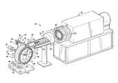
- FIG. 1is a perspective view of the manufacturing apparatus including a pressure-applying device engaging an extrudate wrapped about a mandrel.
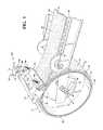
- FIG. 2is a perspective view of a first end of a first layer of the extrudate abutting the mandrel with the pressure-applying device removed.
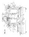
- FIG. 3is a perspective view of the first layer abutting the mandrel, a second layer on top of the first layer, and a third layer being disposed on top of the second layer with the pressure-applying device engaging the third layer.
- FIG. 4is a perspective view of a second end of the third layer cut to define a preform with the pressure-applying device engaging the third layer.
- FIG. 5is an enlarged-broken side view of the layers disposed on top of each other at the first and second ends.
- FIG. 6is a front view of the mandrel including an outer surface being substantially flat with the preform cross-sectioned to illustrate the first, second, and third layers complementary in configuration to the outer surface of the mandrel.
- FIG. 7is a front view of the mandrel of another configuration with the outer surface being tapered and the preform cross-sectioned to illustrate the first, second, and third layers complementary in configuration to the outer surface of the mandrel.
- FIG. 8is an enlarged front view of the mandrel with the outer surface being tapered.
- FIG. 9is a perspective view of another configuration of a pressure-applying device applying pressure to the second layer.
- FIG. 10is a schematic view of the preform in a heating apparatus.
- FIG. 11is a perspective view of the preform after being removed from the mandrel.
- FIG. 12is a perspective view of the manufacturing apparatus including a first mandrel and a second mandrel coupled to a platform movable relative to a multi-screw extruder.
- a manufacturing apparatus 20 for forming a ceramic article or preform 22 from an extrudate 24is generally shown in FIG. 1 . More specifically, the manufacturing apparatus 20 is utilized for forming a ceramic preform 22 from the extrudate 24 .
- the manufacturing apparatus 20includes a multi-screw extruder 26 for processing a composition for forming the extrudate 24 .
- the compositionis mixed in the multi-screw extruder 26 for forming the extrudate 24 .
- the compositiongenerally comprises ceramic particles and ceramic fibers having an aspect ratio of greater than or equal to 10:1.
- the ceramic fibersare substantially randomly orientated in three dimensions. It is to be appreciated that the composition can be manufactured from materials other than ceramic particles and ceramic fibers. The composition will be discussed further below.
- the multi-screw extruder 26includes at least three intermeshing screws 28 for processing the composition to form the extrudate 24 .
- the at least three intermeshing screws 28are formed in a ring configuration. More specifically, the at least three intermeshing screws 28 are generally arranged in a fixed ring configuration and geared to a common motor. In one embodiment, the at least three intermeshing screws 28 are further defined as twelve intermeshing screws 28 which are formed in the ring configuration.
- the screws 28also rotate at a common speed as is known in the industry.
- the screws 28can be co-rotating or counter-rotating. In addition, the screws 28 can be self-wiping. It is to be appreciated that the screws 28 can be any suitable configuration and can rotate as desired.
- Processing the composition for forming or extruding the extrudate 24can be further defined as rotating the at least three intermeshing screws 28 at about 20 to 1,200 rpm and more specifically about 100 to 400 rpm. As the intermeshing screws 28 rotate, the composition is conveyed, mixed, and advanced through the multi-screw extruder 26 until the composition exits the multi-screw extruder 26 .
- the multi-screw extruder 26has a modular design and comprises solid barrels and/or combination barrels.
- the combination barrelsinclude ports for injecting materials and/or for venting volatile gases. It is to be appreciated that one skilled in the art can select a combination of solid barrels and combination barrels to provide desired mixing characteristics of the multi-screw extruder 26 and desired physical properties of the extrudate 24 .
- the multi-screw extruder 26can also include flow blocking flights for providing separate mixing processes in the multi-screw extruder 26 .
- the flow blocking flightscan be flighted and can impede passing of the composition between sections of the multi-screw extruder 26 . It is to be appreciated that certain flow blocking flights can be removed for increasing the feeding capability of the multi-screw extruder 26 .
- the multi-screw extruder 26has 2 to 8 mixing zones, and in one embodiment has 4 to 6 mixing zones. It is to be appreciated that the multi-screw extruder 26 can have more or less mixing zones as desired.
- the multi-screw extruder 26also has an L/D ratio of from about 18 to 56, and in one embodiment has an L/D ratio of from about 20 to 44.
- a suitable multi-screw extruder 26is a 3+ RingExtruder commercially available from Century, Inc. of Traverse City, Mich.
- the multi-screw extruder 26generally elongates and shears the composition to provide distributive and dispersive mixing to both randomly orient the ceramic fibers in three dimensions and homogeneously distribute dispersed the ceramic fibers.
- Extruding the compositiongenerally includes arranging adjacent the ceramic fibers in different dimensions so that adjacent ceramic fibers arranged in different dimensions are present in the extrudate 24 in an amount of greater than 85 parts by volume based on 100 parts by volume of the extrudate 24 . In one embodiment, greater than 85 parts by volume of the ceramic fibers are uniformly distributed on a scale of twice the diameter of the ceramic fibers. That is, the multi-screw extruder 26 provides excellent elongational and low-intensity shear mixing that results in adjacent ceramic fibers oriented in different dimensions in the extrudate 24 .
- the multi-screw extruder 26can also mix an organic binder into the composition.
- the organic bindercomprises cellulose ether.
- Cellulose ethergenerally exhibits reverse thermal gelation and provides lubricity during formation of the preform 22 . Without intending to be limited by theory, it is believed that the cellulose ether also provides surface activity, plasticity, uniform rheology, strength, and uniform distribution of air during formation of the preform 22 .
- Cellulose etheris generally selected from the group of methyl cellulose, hydroxypropylmethylcellulose, hydroxybutylmethylcellulose, and combinations thereof.
- a suitable methyl celluloseis hydroxypropylmethylcellulose, commercially available under the trade name MethocelTM A4M from The Dow Chemical Company of Midland, Mich. It is to be appreciated that any suitable organic binder can be utilized.
- the multi-screw extruder 26can also mix a filler into the composition. It is to be appreciated that one skilled in the art can select the filler to control the density of the extrudate 24 . That is, the filler is included in the composition according to the weight percent of the ceramic particles and the ceramic fibers in the composition. The filler generally spaces out the ceramic particles and the ceramic fibers to provide the extrudate 24 and the preform 22 with the desired density and/or to allow effective metal infiltration during any secondary processing of the preform 22 , such as infiltrating the preform 22 with a metal. The filler is selected to burn off during heating of the extrudate 24 or preform 22 as discussed further below.
- the fillercan be selected from walnut shell flour, cellulose fiber, air, and combinations thereof.
- One example of a suitable filleris walnut shell flour, commercially available under from Ecoshell of Corning, Calif. It is to be appreciated that any suitable filler can be utilized.
- the multi-screw extruder 26can also mix an inorganic binder into the composition.
- the inorganic binderis silica. Without intending to be limited by theory, it is believed that the inorganic binder provides the preform 22 with strength.
- a suitable inorganic binderis silica, commercially available under the trade name Bindzil 1440 Colloidal Silica from Wesbond Corporation of Wilmington, Del. It is to be appreciated that any suitable inorganic binder can be utilized.
- the multi-screw extruder 26includes an exiting end 30 having a die plate 32 coupled to the exiting end 30 of the multi-screw extruder 26 .
- the compositionis defined as the extrudate 24 once the composition has been processed in and exits the multi-screw extruder 26 . As such, once the composition exits the exiting end 30 of the multi-screw extruder 26 , the composition will be referred to as the extrudate 24 .
- the die plate 32shapes the extrudate 24 in a desired configuration as the composition exits the multi-screw extruder 26 . More specifically, the die plate 32 defines a bore 34 of the desired configuration for allowing the composition to pass through the die plate 32 to form the desired configuration of the extrudate 24 .
- the compositionAs the composition exits the multi-screw extruder 26 , the composition is forced through the bore 34 of the die plate 32 .
- the extrudate 24moves away from the multi-screw extruder 26 in a first direction as indicated in FIG. 1 .
- the extrudate 24defines a continuous piece of extrudate 24 as the extrudate 24 exits the exiting end 30 of the multi-screw extruder 26 .
- the extrudate 24can define a generally rectangular cross-section when exiting the die plate 32 . It is to be appreciated that the extrudate 24 can be any suitable configuration.
- the extrudate 24defines an initial temperature of from about 50 to 100 degrees Fahrenheit as the extrudate 24 exits the multi-screw extruder 26 .
- the composition or extrudate 24exits the multi-screw extruder 26 at the initial temperature of from about 50 to 100 degrees Fahrenheit.
- the extrudate 24has a first end 36 defining a first configuration and a second end 38 defining a second configuration with the first and second ends 36 , 38 spaced from each other.
- the extrudate 24includes a first side 40 and a second side 42 opposing the first side 40 .
- the extrudate 24defines the continuous piece of extrudate 24 between the first and second ends 36 , 38 .
- the first configuration and the second configurationare each angled such that the first and second ends 36 , 38 complement each other. More specifically, as best shown in FIG.
- the first end 36 of the extrudate 24defines a first angle ⁇ relative to the first side 40 and the second end 38 of the extrudate 24 defines a second angle ⁇ relative to the second side 42 .
- the first and second ends 36 , 38can be cut at any suitable angle, such as, for example, approximately 45 degrees or less.
- the first and second angles ⁇ , ⁇are each defined as of from about 30 to 45 degrees.
- the first and second angles ⁇ , ⁇are each defined as less than 45 degrees.
- the first and second ends 36 , 38 of the extrudate 24complement each other such that the first and second ends 36 , 38 align with each other in a spaced relationship which is discussed further below. It is to be appreciated that the first and second angles ⁇ , ⁇ have been exaggerated for illustrative purposes only.
- the manufacturing apparatus 20also includes a mandrel 44 adjacent the multi-screw extruder 26 for wrapping the extrudate 24 about the mandrel 44 . More specifically, the mandrel 44 is rotatable about a longitudinal axis L transverse to the first direction. Also referring to FIG. 11 , the mandrel 44 defines an outer diameter OD for wrapping the extrudate 24 about the outer diameter OD to define a plurality of layers 46 disposed on top of each other such that the extrudate 24 defines an inner diameter ID complementary to the outer diameter OD of the mandrel 44 .
- a bracket 48is disposed adjacent the multi-screw extruder 26 for rotatably supporting the mandrel 44 .
- the bracket 48can be any suitable configuration for supporting the mandrel 44 .
- a pivot 47is coupled to the bracket 48 and disposed along the longitudinal axis L with the mandrel 44 concurrently rotatable with the pivot 47 about the longitudinal axis L. It is to be appreciated that the mandrel 44 can rotate independently of the pivot 47 .
- a clamp 49selectively engages one end of the pivot 47 for securing the mandrel 44 to the pivot 47 .
- the pivot 47 and the clamp 49cooperate for allowing the mandrel 44 to be easily removable from the pivot 47 and the bracket 48 , thus automating production of the preform 22 .
- a motor 51is coupled to the pivot 47 for rotating the mandrel 44 about the longitudinal axis L.
- the motor 51rotates the pivot 47 which causes the mandrel 44 to rotate about the longitudinal axis L. It is to be appreciated that the motor 51 can be any suitable horsepower and configuration for rotating the mandrel 44 .
- the mandrel 44includes an outer surface 50 spaced radially from the longitudinal axis L for wrapping the extrudate 24 about the outer surface 50 of the mandrel 44 .
- the extrudate 24is wrapped about the mandrel 44 to form a first layer 52 . More specifically, as the mandrel 44 rotates about the longitudinal axis L, the first side 40 of the first layer 52 abuts the outer surface 50 of the mandrel 44 .
- the extrudate 24can continue to be wrapped about the mandrel 44 to form a second layer 54 on top of the first layer 52 . As such, the first side 40 of the second layer 54 abuts the second side 42 of the first layer 52 as the mandrel 44 continues to rotate about the longitudinal axis L.
- the extrudate 24can continue to be wrapped about the mandrel 44 to form a third layer 56 on top of the second layer 54 . Therefore, the first side 40 of the third layer 56 abuts the second side 42 of the second layer 54 . Hence, the first 52 , second 54 , and third 56 layers overlap each other.
- the layers 46and hence, the first 52 , second 54 , and third 56 layers, each include the first and second sides 40 , 42 .
- the layers 46such as the first 52 , second 54 , and third 56 layers, are wrapped on the outer surface 50 of the mandrel 44 as the mandrel 44 rotates about the longitudinal axis L. It is to be appreciated that one or more layers 46 can be wrapped about the mandrel 44 . It is to further be appreciated that any suitable number of layers 46 can be wrapped about the mandrel 44 .
- the second layer 54ramps up over the first end 36 of the first layer 52 and overlaps the first layer 52 .
- the third layer 56ramps up over the first end 36 in a spaced relationship and overlaps the second layer 54 .
- the first and second ends 36 , 38 of the extrudate 24complement each other such that the first and second ends 36 , 38 of the extrudate 24 align with each other in a spaced relationship.
- having the first and second ends 36 , 38 spaced from each other with at least one layer 46 disposed between the first and second ends 36 , 38minimizes cracking of the preform 22 .
- Each of the layers 46define approximately one revolution about the mandrel 44 . Therefore, for example, the extrudate 24 is wrapped about the mandrel 44 approximately three times to form the first 52 , second 54 , and third 56 layers.
- the manufacturing apparatus 20includes a cutter 58 for forming the first and second ends 36 , 38 of the extrudate 24 complementary to each other such that the first and second ends 36 , 38 of the extrudate 24 align with each other in a spaced relationship to define the preform 22 having a substantially uniform exterior surface 60 and a substantially uniform thickness T.
- the first and second ends 36 , 38are cut to align with each other in a spaced relationship to define the preform 22 .
- the exterior surface 60 of the preform 22is an exposed side of the last layer 52 , 54 , 56 .
- the substantially uniform thickness Tis the total combined thickness T of the layers 52 , 54 , 56 as identified in FIGS. 6 and 7 . Further, having the substantially uniform thickness T of the preform 22 also minimizes cracking of the preform 22 .
- the extrudate 24 exiting the die plate 32must be cut to form the first end 36 defining the first angle ⁇ .
- a portion of the first layer 52is disposed on the outer surface 50 of the mandrel 44 and then the first layer 52 is cut to form the first end 36 defining the first angle ⁇ .
- the first end 36 of the first layer 52can be cut before being disposed on the outer surface 50 of the mandrel 44 .
- the first and second ends 36 , 38can be cut by any suitable machine, device, apparatus, by hand, etc.
- the cutter 58can be defined as a knife, etc. As such, in one embodiment, the extrudate 24 is cut by hand with the knife.
- the preform 22 and the mandrel 44are ready for the next step of the process, and therefore, are ready to be removed from the bracket 48 .
- Another mandrelcan be rotatably coupled to the bracket 48 for forming another preform, and so on.
- the mandrel 44 and the preform 22can be removed from the bracket 48 and replaced by another mandrel for repeating the process of wrapping the extrudate 24 about the second mandrel to form a second preform, etc. Therefore, cutting the second end 38 of the previous preform 22 is also the first end 36 of the next preform.
- cutting the second end 38 to the second angle ⁇ for the previous preform 22also creates the first angle ⁇ of the first end 36 of the next preform. It is to be appreciated that the first end 36 can be re-cut if desired when starting the next preform.
- the second end 38 of the preform 22defines a seam 62 on the exterior surface 60 of the preform 22 .
- the second end 38 or seam 62is adhered and/or leveled into the second side 42 of the last layer 52 , 54 , 56 to further define the substantially uniform exterior surface 60 .
- the second end 38 or seam 62is blended or massaged into the second side 42 of the last layer 52 , 54 , 56 to integrate or combine the second end 38 into the last layer 52 , 54 , 56 .
- the ceramic particles and ceramic fibers, etc. of the second end 38 of one layer 52 , 54 , 56is blended/integrated with the ceramic particles and ceramic fibers, etc. of another layer 52 , 54 , 56 .
- the extrudate 24defines the preform 22 when the desired number of layers 46 are wrapped about the mandrel 44 and the second end 38 is cut.
- the first and second layers 52 , 54define the preform 22 once the second end 38 is cut with the second side 42 of the second layer 54 being the exposed side and thus defining the exterior surface 60 of the preform 22 .
- the first 52 , second 54 , and third 56 layersdefine the preform 22 once the second end 38 is cut.
- the first 52 , second 54 , and third 56 layersare wrapped on top of each other on the mandrel 44 with the second side 42 of the third layer 56 being the exposed side and thus defining the exterior surface 60 of the preform 22 .
- the second end 38can be blended or massaged to smooth the last layer 52 , 54 , 56 and/or decrease the visibility of the second end 38 , etc. It is to be appreciated that the desired number of layers 46 wrapped about the mandrel 44 are one continuous piece of extrudate 24 .
- a first substancecan be applied to the first and second ends 36 , 38 for increasing adhesion of the extrudate 24 .
- the first substanceis applied to the first end 36 prior to wrapping the extrudate 24 about the mandrel 44 .
- the first substanceis applied to the second end 38 after wrapping the extrudate 24 about the mandrel 44 .
- the first substancecan be applied to any of the layers 46 of the extrudate 24 .
- the first substancecan be of any suitable composition, including water, to increase adhesion.
- the mandrel 44is cooled to a first temperature for adhering the extrudate 24 to the mandrel 44 .
- the mandrel 44is cooled such that the extrudate 24 sticks to the mandrel 44 .
- the mandrel 44is cooled such that the first side 40 of the first layer 52 adheres to the outer surface 50 of the mandrel 44 . Having the extrudate 24 adhere or stick to the mandrel 44 allows the first layer 52 to remain attached to the outer surface 50 of the mandrel 44 as the mandrel 44 rotates about the longitudinal axis L.
- the first temperature of the mandrel 44is below room temperature.
- the first temperature of the mandrel 44is above 40 and below 70 degrees Fahrenheit. In another embodiment, the first temperature of the mandrel 44 is of from about 40 to 60 degrees Fahrenheit. In yet another embodiment, the first temperature of the mandrel 44 is of from about 40 to 50 degrees Fahrenheit.
- the mandrel 44is formed of a metal material.
- the metal material of the mandrel 44is an alloy. Suitable alloys include aluminum and/or iron alloys. It is to be appreciated that the mandrel 44 can be formed of other material(s).
- the outer surface 50 of the mandrel 44includes a first edge 64 and a second edge 66 spaced from each other with the outer diameter OD defined between the first and second edges 64 , 66 .
- the outer surface 50 of the mandrel 44defines an angle ⁇ relative to a plane P parallel to the longitudinal axis L. In one embodiment, the angle ⁇ of the outer surface 50 is 0 degrees such that the outer surface 50 is substantially flat as shown in FIG. 6 . Hence, the outer diameter OD of the mandrel 44 remains the same between the first and second edges 64 , 66 .
- the angle ⁇ of the outer surface 50is greater than 0 degrees and less than 3 degrees such that the outer surface 50 is substantially tapered as shown in FIGS. 7 and 8 .
- the outer diameter OD of the mandrel 44changes between the first and second edges 64 , 66 .
- the outer diameter OD of the mandrel 44increases from one of the first and second edges 64 , 66 to the other one of the first and second edges 64 , 66 .
- the outer diameter OD of the mandrel 44 adjacent the first edge 64is less than the outer diameter OD of the mandrel 44 adjacent the second edge 66 with the outer diameter OD gradually increasing from the first edge 64 toward the second edge 66 .
- the angle ⁇ of the outer surface 50is further defined as of from about 0.5 to 2.0 degrees. In one embodiment, the angle ⁇ of the outer surface 50 is defined as 0.75 degrees. It is to be appreciated that the angle ⁇ of the outer surface 50 can be any suitable degree.
- the outer surface 50 of the mandrel 44aids in releasing or removing the preform 22 from the mandrel 44 .
- the changing outer diameter OD of the outer surface 50improves the ability to release or remove the preform 22 from the mandrel 44 .
- Utilizing the mandrel 44 including the outer surface 50 having the taperreduces frictional engagement between the preform 22 and the mandrel 44 as the preform 22 is removed from the mandrel 44 . More specifically, sliding friction is progressively reduced as the preform 22 separates from the mandrel 44 when utilizing the mandrel 44 including the outer surface 50 having the taper.
- the preform 22is removed over the first edge 64 until the preform 22 is completely removed from the mandrel 44 .
- the preform 22is removed from the first edge 64 of the mandrel 44 defining the smaller outer diameter OD.
- the inner diameter ID of the preform 22becomes spaced from the outer diameter OD of the mandrel 44 due to the taper and thus frictional engagement between the preform 22 and the mandrel 44 is reduced.
- the preform 22is removed from the mandrel 44 after the preform 22 has been dried as discussed further below.
- the manufacturing apparatus 20further includes a pressure-applying device 68 adjacent the mandrel 44 for applying pressure to the layers 46 of the extrudate 24 . More specifically, the pressure-applying device 68 applies pressure to the layers 46 as the mandrel 44 rotates about the longitudinal axis L. Hence, the pressure-applying device 68 engages the extrudate 24 for applying pressure to the extrudate 24 to adhere and/or level the layers 46 to further define the substantially uniform thickness T.
- the pressure-applying device 68applies pressure to the first 52 , second 54 , and third 56 layers as the mandrel 44 rotates about the longitudinal axis L, thus blending, integrating, or combining the second layer 54 to the first layer 52 and blending, integrating, or combining the third layer 56 to the second layer 54 .
- the ceramic particles and ceramic fibers, etc. of one layer 52 , 54 , 56are blended/integrated with the ceramic particles and ceramic fibers, etc. of another layer 52 , 54 , 56 .
- the pressure-applying device 68levels each of the layers 46 and/or levels the exterior surface 60 of the preform 22 to further defining the substantially uniform exterior surface 60 .
- pressureis applied after the first end 36 of the first layer 52 is disposed on the mandrel 44 and/or after the first end 36 is cut to the first angle ⁇ .
- the application of pressure to level the extrudate 24ensures a strong bond between the layers 46 that abut each other.
- the pressure-applying device 68can be disposed adjacent the mandrel 44 . Further, the pressure-applying device 68 can be attached to the bracket 48 or spaced from the bracket 48 as shown in FIGS. 1 and 9 .
- a brace 70is disposed adjacent the mandrel 44 for supporting the pressure-applying device 68 .
- the brace 70can be coupled to the pivot 47 and/or attached to the bracket 48 .
- the pressure-applying device 68is shown schematically and can be of any suitable configuration. FIGS. 1 , 3 , and 4 illustrate one configuration of the pressure-applying device 68 and FIG. 9 illustrates another configuration of the pressure-applying device 68 .
- the pressure-applying device 68includes a shaft 72 rotatable about a central axis C with at least one support 76 mounted to the shaft 72 .
- the support 76is further defined as a plurality of supports 76 mounted to the shaft 72 and spaced from each other. As such, rotation of the support 72 about the central axis C also causes concurrent rotation of the support(s) 76 about the central axis C.
- the pressure-applying devicecan include a sleeve (not shown) disposed about the shaft 72 and rotatable about the central axis C.
- the sleeveis attached to the shaft 72 such that the shaft 72 and the sleeve concurrently rotate about the central axis C and/or tilt as discussed below.
- the support(s) 76are mounted to the sleeve. It is to be appreciated that the support(s) 76 can be mounted to the shaft 72 or the sleeve by any suitable method, such as for example, welding, press fit, adhesive, fasteners, etc.
- the pressure-applying device 68includes a roller 78 engaging the layers 46 with the roller 78 being rotatable.
- the roller 78is coupled to the support(s) 76 such that the roller 78 is rotatable relative to the support(s) 76 .
- the roller 78is coupled to the shaft 72 through the support(s) 76 .
- the roller 78rotates as the roller 78 engages the extrudate 24 or the layers 46 . In other words, the roller 78 rotates during engagement of the extrudate 24 or the layers 46 as the extrudate 24 is wrapped about the mandrel 44 .
- the roller 78can also concurrently rotate with the support(s) 76 and the shaft 72 about the central axis C such that the roller 78 moves up and/or down relative to the extrudate 24 or the layers 46 to compensate for variances of the extrudate 24 or the layers 46 . As such, the roller 78 is allowed to float or adjust as the extrudate 24 is wrapped about the mandrel 44 .
- the roller 78can rotate with the support(s) 76 and the shaft 72 about the central axis C for preventing the roller 78 from engaging the mandrel 44 when preparing to wrap the layers 46 .
- the roller 78can rotate with the support(s) 76 and the shaft 72 about the central axis C for preventing the roller 78 from engaging the preform 22 when preparing to remove the mandrel 44 and the preform 22 from the pivot 47 or when preparing to couple the mandrel 44 to the pivot 47 .
- the shaft 72defines a slot 80 with a pin 82 disposed through the brace 70 and in the slot 80 for securing the roller 78 out of engagement from the mandrel 44 or the preform 22 .
- the pin 82engages the slot 80 for maintain the roller 78 in an upward position for preventing the roller 78 from engaging the mandrel 44 or the preform 22 . It is to be appreciated that the roller 78 can be secured out of engagement from the mandrel 44 or the preform 22 by any suitable method.
- an amount of pressure being applied to the layers 46can be adjusted by changing the weight of the roller 78 . In another embodiment, the amount of pressure being applied to the layers 46 can be adjusted by coupling a weight to the roller 78 . More specifically, at least one post 84 extends from one of the support(s) 76 for coupling one or more weights to the post 84 .
- the post 84can be further defined as a plurality of posts 84 with one of the posts 84 extending from one of the supports 76 and another one of the posts 84 extending from another one of the supports 76 . It is to be appreciated that the posts 84 and the supports 76 supporting the posts 84 are spaced from the roller 78 for allowing the roller 78 to rotate without interference from the posts 84 or the supports 76 .
- the pressure-applying device 68is disposed complementary to the outer surface 50 of the mandrel 44 for engaging the layers 46 . More specifically, when utilizing the three layers 46 , the pressure-applying device 68 engages the first 52 , second 54 , and third 56 layers as the mandrel 44 rotates about the longitudinal axis L. Specifically, the roller 78 is disposed complementary to the outer surface 50 of the mandrel 44 for engaging the layers 46 or the extrudate 24 .
- the pressure-applying device 68includes an adjuster 86 for complementing the outer surface 50 of the mandrel 44 .
- the adjuster 86allows the pressure-applying device 68 to remain substantially parallel to the outer surface 50 of the mandrel 44 .
- the adjuster 86allows the roller 78 to adjust in light of the configuration of the outer surface 50 of the mandrel 44 . Therefore, the adjuster 86 allows the pressure-applying device 68 , and more specifically, the roller 78 , to be substantial parallel to the outer surface 50 when flat or tapered while allowing the roller 78 to apply pressure to the layers 46 .
- the adjuster 86is coupled to the brace 70 and the shaft 72 . More specifically, the adjuster 86 is coupled to an end of the shaft 72 and disposed through the brace 70 .
- the adjuster 86is threaded and includes a nut 88 cooperating with the threads of the adjuster 86 . As such, tightening or loosening the nut 88 causes the adjuster 86 to move the shaft 72 to a desired position which adjusts the roller 78 relative to the outer surface 50 of the mandrel 44 . In other words, threading the nut 88 on the adjuster 86 up or down causes the adjuster 86 to move the shaft 72 and correspondingly move the support(s) 76 .
- the adjuster 86allows the shaft 72 and thus the roller 78 to selectively tilt.
- the adjuster 86allows the shaft 72 to rotate about the central axis C relative to the adjuster 86 .
- the adjuster 86does not rotate about the central axis C.
- the adjuster 86can be further defined as a tie rod rotatably attached to the shaft 72 .
- bearingscan be utilized for rotatably supporting the shaft 72 .
- the adjuster 86can be any suitable configuration for adjusting the roller 78 complementary to the outer surface 50 of the mandrel 44 while also allowing the roller 78 to compensate for variances of the extrudate 24 .
- the adjuster 86is shown schematically with the shaft 72 eliminated such that the support 76 is directly coupled to the roller 78 and the adjuster 86 .
- the brace 70defines an aperture 90 generally complementary to the adjuster 86 for removing the adjuster 86 from the brace 70 .
- the shaft 72is removed from one side of the brace 70 and the adjuster 86 is removed from another side of the brace 70 .
- the adjuster 86is removed from the side of the brace 90 defining the aperture 90 .
- the adjuster 86 and the shaft 72can both be removed from the brace 70 through the aperture 90 .
- the adjuster 86 and the shaft 72can be removed from the brace 70 by any suitable method.
- a second substancecan be applied to the extrudate 24 prior to or simultaneously with applying pressure to the extrudate 24 for assisting with the leveling of the extrudate 24 .
- the second substancecan also be of any suitable composition, including water, to increase adhesion.
- the second substancecan be applied to the second side 42 of the layers 46 for assisting the pressure-applying device 68 to level the second side 42 of the layers 46 .
- the manufacturing apparatus 20can also include a plurality of second cutters 92 adjacent the mandrel 44 for trimming the extrudate 24 or the layers 46 as the extrudate 24 or the layers 46 are wrapped about the mandrel 44 .
- the extrudate 24includes a first outer edge 94 and a second outer edge 96 spaced from each other adjacent the first and second sides 40 , 42 with one of the second cutters 92 adjacent the first outer edge 94 and another one of the second cutters 92 adjacent the second outer edge 96 .
- One of the second cutters 92trims or cuts the first outer edge 94 of the extrudate 24 and the other one of the second cutters 92 trims or cuts the second outer edge 96 of the extrudate 24 .
- the second cutters 92can be rotated relative to the mandrel 44 for adjusting the position of the second cutters 92 . It is to be appreciated that the first and second outer edges 94 , 96 can be trimmed or cut by any suitable machine, device, apparatus, by hand, etc. For example, the second cutters 92 can be defined as a knife, etc. It is to be appreciated that the second cutters 92 as shown in FIG. 1 are rotated out of engagement from the layers 46 for illustrative purposes only.
- the manufacturing apparatus 20can also include a heating apparatus 98 , such as an oven or a kiln.
- the heating apparatus 98is shown schematically and it is to be appreciated that the preform 22 can be heated by other methods, such as an open heat source.
- the heating apparatus 98heats the preform 22 to a plurality of elevated temperatures.
- the preform 22is placed in the heating apparatus 98 and heated to a second temperature.
- the preform 22is disposed on the mandrel 44 during this heating to the second temperature. It is to be appreciated that the preform 22 can be heated to the second temperature by alternative methods.
- the second temperatureis of from about 70 to 200 degrees Fahrenheit.
- heatingis utilized for evaporating water, burning off any organic binder and filler from the preform 22 , and setting the inorganic binder to strengthen the preform 22 , which defines void space in the preform 22 .
- the mandrel 44 with the preform 22i.e., the mandrel 44 with the wrapped layers 46 of the extrudate 24 , is disposed in the oven as a single unit. It should be appreciated that heating the preform 22 can be accomplished through a variety of different methods.
- the preform 22is heated to the second temperature to dry the preform 22 .
- the preform 22is known as an uncured ceramic article.
- the preform 22is held at the second temperature until a gel point of the organic binder is reached which occurs after about 90 to 240 minutes.
- the preform 22is then removed from the heating apparatus 98 and the mandrel 44 .
- the preform 22is again placed into the heating apparatus 98 and again heated to the second temperature until the moisture content of the preform 22 is of from about 0 to 18 percent, and more specifically, of from about 5 to 10 percent.
- the preform 22is subsequently heated to a third temperature for about 30 to 90 minutes and more specifically for about 60 minutes for burning off the organic binders and the fillers within the composition.
- the third temperatureis of from about 450 to 700 degrees Fahrenheit and more specifically of from about 475 to 525 degrees Fahrenheit.
- the preform 22is then heated to a fourth temperature for about 90 to 150 minutes and more specifically for about 105 to 135 minutes to set the inorganic binder and provide the preform 22 with excellent strength at high temperatures.
- the fourth temperatureis of from about 1,600 to 2,000 degrees Fahrenheit and more specifically of from about 1,700 to 1,900 degrees Fahrenheit.
- the preform 22can be referred to as a cured or sintered ceramic article.
- the preform 22can also be machined to a final configuration if desired.
- FIG. 11illustrates the preform 22 removed from the mandrel 44 after being heated, etc. and the layers 52 , 54 , 56 secured to each other to further define the uniform thickness T.
- the dash-dot-dot-dash lines of FIG. 11represent where the initially wrapped layers 52 , 54 , 56 were prior to curing the preform 22 .
- the configuration of the preform 22i.e., the wrapped layers 46 , allows the preform 22 to be removed from the mandrel 44 without being damaged.
- the preform 22can be removed from the mandrel 44 without the layers 46 or the first and second ends 36 , 38 separating, and additional, can be removed from the mandrel 44 without cracking the preform 22 .
- the manufacturing apparatus 20can be utilized to automate production of the preforms 22 .
- the mandrel 44is further defined as a first mandrel 44 and the manufacturing apparatus 20 further includes a second mandrel 100 spaced from the first mandrel 44 .
- the second mandrel 100includes the same components as described above for the first mandrel 44 , and therefore, the features of the second mandrel 100 will not be discussed further.
- the outer surface 50 of the second mandrel 100can be flat or tapered as discussed above.
- the second mandrel 100is supported by a second bracket 102 .
- a second pivot 104is coupled to the second bracket 102 with a second motor 106 coupled to the second pivot 104 for rotating the second mandrel 100 .
- the second mandrel 100can be selectively secured to the second pivot 104 by another clamp 49 engaging one end of the second pivot 104 .
- the second pivot 104 and the clamp 49cooperate for allowing the second mandrel 100 to be easily removable from the second pivot 104 and the second bracket 102 , thus automating production of the preforms 22 .
- the second motor 106is coupled to the second pivot 104 for rotating the second mandrel 100 about the longitudinal axis L.
- the second motor 106rotates the second pivot 104 which causes the second mandrel 100 to rotate about the longitudinal axis L.
- the second motor 106can be any suitable horsepower and configuration for rotating the second mandrel 100 .
- a second pressure-applying device 108is utilized with the second mandrel 100 .
- the second pressure-applying device 108is a minor image of the pressure-applying device 68 discussed above, and therefore, the second pressure-applying device 108 includes the same components which will not be discussed further.
- the pressure-applying device 68 for the first mandrel 44is illustrated with the roller 78 engaging the outer surface 50 of the first mandrel 44
- the second pressure-applying device 108 for the second mandrel 100is illustrated with the roller 78 in the upward position with the roller 78 prevented from engaging the preform 22 or the second mandrel 100 .
- the second pressure-applying device 108can be configured as illustrated in the embodiment of FIG. 9 .
- the first and second mandrels 44 , 100are spaced from each other such that the first mandrel 44 can be removed from the pivot 47 without interfering with the second mandrel 100 .
- the second mandrel 100can be removed from the second pivot 104 without interfering with the first mandrel 44 .
- the first and second mandrels 44 , 100are easily removable from the pivot 47 and the second pivot 104 respectively for automating production of the preforms 22 .
- the manufacturing apparatus 20further includes a platform 110 supporting the first and second mandrels 44 , 100 for automating production of the preforms 22 .
- the bracket 48 that supports the first mandrel 44is attached to the platform 110 and the second bracket 102 that supports the second mandrel 100 is also attached to the platform 110 .
- the brace 70 that supports the pressure-applying device 68can be attached to the platform 110 and another brace 70 that supports the second pressure-applying device 108 can be attached to the platform 110 .
- the platform 110is movable relative to the multi-screw extruder 26 such that the first and second mandrels 44 , 100 move relative to the multi-screw extruder 26 for wrapping the extrudate 24 about one of the first and second mandrels 44 , 100 while an other one of the first and second mandrels 44 , 100 is removable from the platform 110 .
- the platform 110moves transverse to the first direction of the extrudate 24 .
- the platform 110moves back and forth such that one of the first and second mandrels 44 , 100 align with the extrudate 24 exiting the die plate 32 of the multi-screw extruder 26 while the other one of the first and second mandrels 44 , 100 is offset from the extrudate 24 .
- the first mandrel 44is aligned with the exiting end 30 of the multi-screw extruder 26 while the second mandrel 100 is offset from the exiting end 30 .
- the preform 22is ready for the next step in the process. Therefore, the platform 110 moves transverse to the first direction such that the second mandrel 100 aligns with the extrudate 24 to wrap the extrudate 24 about the second mandrel 100 to form another preform 22 .
- the preform 22 disposed on the first mandrel 44can be removed and a third mandrel (not shown) can be coupled to the pivot 47 to form yet another preform 22 .
- this preform 22is ready for the next step in the process.
- the platform 110again moves transverse to the first direction such that the third mandrel aligns with the extrudate 24 to wrap the extrudate 24 about the third mandrel to form yet another preform 22 .
- This processcontinues until the desired number of preforms 22 are formed.
- the platform 110automates production of the preforms 22 , thus more efficiently increasing output of the preforms 22 .
- the present inventionfurther provides a method of forming the preform 22 from the extrudate 24 having the first end 36 and the second end 38 utilizing the mandrel 44 .
- the method as discussed hereincan be accomplished by utilizing the manufacturing apparatus 20 as discussed above or by any other suitable apparatus.
- the compositionis processed within the multi-screw extruder 26 with the composition extruded through the die plate 32 to form the extrudate 24 .
- Forming the extrudate 24can be accomplished by utilizing the multi-screw extruder 26 and the die plate 32 as discussed above or any other suitable process.
- the methodincludes the steps of forming the first end 36 of the extrudate 24 , wrapping the extrudate 24 about the mandrel 44 to form the first layer 52 having the first end 36 abutting the mandrel 44 , and applying pressure to the first layer 52 during wrapping of the extrudate 24 about the mandrel 44 .
- the first end 36 of the extrudate 24defines the first angle ⁇ relative to the first side 40 as discussed above and the step of forming the first end 36 is further defined as the step of cutting the first end 36 to the first angle ⁇ .
- the methodfurther includes the steps of forming the second end 38 of the extrudate 24 complementary in configuration to the first end 36 , wrapping the extrudate 24 about the mandrel 44 to form the second layer 54 on top of the first layer 52 with the second end 38 spaced from the mandrel 44 , and applying pressure to the second layer 54 during wrapping of the extrudate 24 about the mandrel 44 .
- the second end 38 of the extrudate 24defines the second angle ⁇ relative to the second side 42 as discussed above and the step of forming the second end 38 is further defined as the step of cutting the second end 38 to the second angle ⁇ .
- the extrudate 24is defined as the continuous piece of extrudate 24 between the first and second ends 36 , 38 as discussed above and the steps of wrapping the extrudate 24 about the mandrel 44 is further defined as the steps of wrapping the continuous piece of extrudate 24 about the mandrel 44 to form the first and second layers 52 , 54 .
- the step of forming the first end 36occurs before the step of forming the second end 38 and additionally, the step of forming the first end 36 occurs before the step of wrapping the extrudate 24 about the mandrel 44 to form the second layer 54 . Further, the step of forming the second end 38 occurs after the step of wrapping the extrudate 24 about the mandrel 44 to form the second layer 54 . In addition, the step of applying pressure to the first layer 52 occurs before the step of applying pressure to the second layer 54 .
- the extrudate 24includes the first side 40 and the second side 42 opposing the first side 40 such that the first and second layers 52 , 54 include the first and second sides 40 , 42 as discussed above.
- the step of wrapping the extrudate 24 about the mandrel 44 to form the first layer 52is further defined as abutting the first side 40 of the first layer 52 to the mandrel 44 .
- the step of wrapping the extrudate 24 about the mandrel 44 to form the second layer 54is further defined as abutting the first side 40 of the second layer 54 to the second side 42 of the first layer 52 .
- the methodfurther includes the step of wrapping the extrudate 24 about the mandrel 44 to form the third layer 56 on top of the second layer 54 .
- the extrudate 24is defined as the continuous piece of extrudate 24 such that the steps of wrapping the extrudate 24 about the mandrel 44 is further defined as the steps of wrapping the continuous piece of extrudate 24 about the mandrel 44 to form the first 52 , second 54 , and third 56 layers.
- the step of forming the first end 36occurs before the step of forming the second end 38 .
- the steps of applying pressure to the first and second layers 52 , 54are further defined as the steps of applying pressure to the first 52 , second 54 , and third 56 layers during wrapping of the extrudate 24 about the mandrel 44 .
- the step of applying pressure to the first layer 52occurs before the steps of applying pressure to the second and third layers 54 , 56 . More specifically, the steps of applying pressure to the first and second layers 52 , 54 occur before the step of applying pressure to the third layer 56 .
- the methodalso includes the step of aligning the second end 38 complementary to the first end 36 of the first layer 52 in the spaced relationship to define the preform 22 having the substantially uniform exterior surface 60 and the substantially uniform thickness T.
- the second layer 54has the second end 38 and the step of aligning the second end 38 complementary to the first end 36 of the first layer 52 in the spaced relationship is further defined as the step of aligning the second end 38 of the second layer 54 complementary to the first end 36 of the first layer 52 in the spaced relationship to define the preform 22 having the substantially uniform exterior surface 60 and the substantially uniform thickness T.
- the third layer 56has the second end 38 and the step of aligning the second end 38 complementary to the first end 36 of the first layer 52 in the spaced relationship is further defined as the step of aligning the second end 38 of the third layer 56 complementary to the first end 36 of the first layer 52 in the spaced relationship to define the preform 22 having the substantially uniform exterior surface 60 and the substantially uniform thickness T.
- the present inventionalso provides a method of forming the ceramic preform 22 comprising ceramic particles and ceramic fibers having an aspect ratio of greater than or equal to 10:1 and the ceramic fibers substantially randomly orientated in three dimensions utilizing the mandrel 44 and the extruder 26 as discussed above.
- This methodis similar to the method discussed above and therefore can include the steps discussed above for the other method. Only a few of the steps for this other method are set forth below for illustrative purposes.
- the methodincludes the step of extruding the ceramic particles and the ceramic fibers through the extruder 26 to form the extrudate 24 having the first end 36 and the second end 38 .
- the methodfurther includes the steps of forming the first end 36 of the extrudate 24 , wrapping the extrudate 24 about the mandrel 44 to form the first layer 52 having the first end 36 abutting the mandrel 44 , and applying pressure to the first layer 52 during wrapping of the extrudate 24 about the mandrel 44 .
- the methodincludes the steps of forming the second end 38 of the extrudate 24 complementary in configuration to the first end 36 , wrapping the extrudate 24 about the mandrel 44 to form the second layer 54 on top of the first layer 52 with the second end 38 spaced from the mandrel 44 , and applying pressure to the second layer 54 during wrapping of the extrudate 24 about the mandrel 44 .
- the methodalso includes the step of aligning the second end 38 complementary to the first end 36 of the first layer 52 in the spaced relationship to define the preform 22 having the substantially uniform exterior surface 60 and the substantially uniform thickness T.
- the methodfurther includes the step of wrapping the extrudate 24 about the mandrel 44 to form the third layer 56 on top of the second layer 54 .
- the extrudate 24is defined as the continuous piece of extrudate 24 between the first and second ends 36 , 38 such that the steps of wrapping the extrudate 24 about the mandrel 44 is further defined as the steps of wrapping the continuous piece of extrudate 24 about the mandrel 44 to form the first 52 , second 54 , and third 56 layers.
- the third layer 56has the second end 38 and the step of aligning the second end 38 complementary to the first end 36 of the first layer 52 in the spaced relationship is further defined as the step of aligning the second end 38 of the third layer 56 complementary to the first end 36 of the first layer 52 in the spaced relationship to define the preform 22 having the substantially uniform exterior surface 60 and the substantially uniform thickness T.
- the methods as discussed abovecan include various additional steps.
- the methodscan further include the steps of cooling the mandrel 44 and/or heating the preform 22 to one or more temperatures, as discussed above, etc.
- the preform 22may be heated, fired, and/or sintered at any temperature as selected by one of skill in the art. After heating, the preform 22 may be described as the ceramic article.
- the ceramic articleincludes the firing (or sintering) product of ceramic particles, ceramic fibers having an aspect ratio of greater than or equal to 10:1, an organic binder comprising a cellulose ether, an inorganic binder comprising silica; and water. It is contemplated that greater than 90 out of 100 ceramic fibers may be randomly oriented in three dimensions in the ceramic article. Additionally, greater than 85 parts by volume of the ceramic fibers may be uniformly distributed in the ceramic article on a scale of twice the diameter of the ceramic fibers.
- the ceramic articlemay have a consistent density of from 0.9 to 1.1 g/cm 3 in x-, y-, and z-dimensions and/or have a uniform strength in three dimensions as measured in accordance with ASTM C1424.
- the ceramic fibersare present in the ceramic article in an amount of from 3 to 15 parts by volume based on 100 parts by volume of the ceramic article.
- the ceramic fiberscomprise an element from period 2, 3, 4, or 5 of the periodic table of the elements, such as aluminum, silicon, oxygen, zirconium, or carbon.
- the ceramic fibersmay be selected from the group of alumina-silica fibers, alumina-silica-zirconia fibers, carbon-graphite fibers, and combinations thereof.
- the ceramic particlesare present in the ceramic article in an amount of from 15 to 30 parts by volume based on 100 parts by volume of the ceramic article.
- the ceramic particlesmay include an element from period 2, 3, or 4 of the periodic table of the elements such as silicon, oxygen, carbon, aluminum, or boron.
- the ceramic particlesmay be selected from the group of silicon carbide, alumina, boron carbide, and combinations thereof.
- the ceramic articleis as described in U.S. patent application Ser. No. 12/174,982, which is expressly incorporated herein by reference.
Landscapes
- Engineering & Computer Science (AREA)
- Chemical & Material Sciences (AREA)
- Ceramic Engineering (AREA)
- Manufacturing & Machinery (AREA)
- Mechanical Engineering (AREA)
- Materials Engineering (AREA)
- Structural Engineering (AREA)
- Organic Chemistry (AREA)
- Inorganic Chemistry (AREA)
- Composite Materials (AREA)
- Chemical Kinetics & Catalysis (AREA)
- Press-Shaping Or Shaping Using Conveyers (AREA)
Abstract
Description
Claims (27)
Priority Applications (1)
| Application Number | Priority Date | Filing Date | Title |
|---|---|---|---|
| US13/149,292US9283734B2 (en) | 2010-05-28 | 2011-05-31 | Manufacturing apparatus and method of forming a preform |
Applications Claiming Priority (2)
| Application Number | Priority Date | Filing Date | Title |
|---|---|---|---|
| US39659610P | 2010-05-28 | 2010-05-28 | |
| US13/149,292US9283734B2 (en) | 2010-05-28 | 2011-05-31 | Manufacturing apparatus and method of forming a preform |
Publications (2)
| Publication Number | Publication Date |
|---|---|
| US20120183707A1 US20120183707A1 (en) | 2012-07-19 |
| US9283734B2true US9283734B2 (en) | 2016-03-15 |
Family
ID=46490979
Family Applications (1)
| Application Number | Title | Priority Date | Filing Date |
|---|---|---|---|
| US13/149,292Active2033-03-10US9283734B2 (en) | 2010-05-28 | 2011-05-31 | Manufacturing apparatus and method of forming a preform |
Country Status (1)
| Country | Link |
|---|---|
| US (1) | US9283734B2 (en) |
Families Citing this family (4)
| Publication number | Priority date | Publication date | Assignee | Title |
|---|---|---|---|---|
| US7793703B2 (en)* | 2008-06-17 | 2010-09-14 | Century Inc. | Method of manufacturing a metal matrix composite |
| DE102017003122B4 (en)* | 2017-03-30 | 2025-08-28 | Richard Koplar | Dough winding machine |
| FR3071765B1 (en)* | 2017-10-03 | 2020-11-20 | Safran Ceram | COMPOSITE MATERIAL REALIZATION OF A FLOW MIXER LOBE STRUCTURE |
| US20240181665A1 (en)* | 2021-03-19 | 2024-06-06 | Vibracoustic Cv Air Spring Otomotiv Sanayi Ve Ticaret Anonim Sirketi | Automatic apparel machine |
Citations (116)
| Publication number | Priority date | Publication date | Assignee | Title |
|---|---|---|---|---|
| US1768451A (en)* | 1930-06-24 | Pipes | ||
| GB410734A (en)* | 1932-08-18 | 1934-05-24 | Hans Hatschek | Process for the manufacture of hollow bodies from mixtures of fibrous materials and hydraulic binding agents |
| US2196570A (en)* | 1937-06-10 | 1940-04-09 | Russell Mfg Co | Clutch friction disk |
| US2262242A (en) | 1938-03-24 | 1941-11-11 | Frank J Lenox | Container |
| GB674994A (en) | 1949-10-14 | 1952-07-02 | British Insulated Callenders | Improvements in insulated electric conductors |
| US2671939A (en)* | 1950-04-28 | 1954-03-16 | Nat Clay Pipe Res Corp | Method and apparatus for forming tubular ceramic bodies |
| US2724671A (en)* | 1952-12-30 | 1955-11-22 | Johns Manville | Friction element and method of making the same |
| US3002433A (en) | 1958-01-10 | 1961-10-03 | Sonoco Products Co | Spiral wound paper tube having seamless outer surface |
| US3005259A (en) | 1958-11-24 | 1961-10-24 | Chrysler Corp | Method of making brake drums |
| US3007553A (en) | 1958-05-19 | 1961-11-07 | Keisey Hayes Company | Brake drum |
| US3066766A (en) | 1961-04-04 | 1962-12-04 | Robert N Minor | Quick change brake lining |
| US3090114A (en) | 1958-12-29 | 1963-05-21 | Kelsey Hayes Co | Method of making a brake drum |
| US3126306A (en) | 1964-03-24 | Attoxj | ||
| US3388017A (en) | 1963-12-18 | 1968-06-11 | American Can Co | Tube making method and apparatus |
| US3564661A (en) | 1967-11-06 | 1971-02-23 | Uniroyal Inc | Flexible mandrels |
| US3697718A (en) | 1970-02-13 | 1972-10-10 | Mannesmann Ag | Method for manufacturing welded pipes or tubes with helical seam |
| US3743069A (en)* | 1971-06-24 | 1973-07-03 | Johns Manville | Glass fiber friction element |
| US3794538A (en) | 1970-07-13 | 1974-02-26 | Goodyear Tire & Rubber | Method of making a rolling lobe diaphragm |
| US3841448A (en) | 1973-06-14 | 1974-10-15 | Budd Co | Reinforced brake drum |
| US3870581A (en) | 1972-05-10 | 1975-03-11 | Johns Manville | Friction element and method of making same |
| US3933565A (en) | 1972-11-20 | 1976-01-20 | Semperit Aktiengesellschaft | Method and apparatus for butt connection of plies formed of plastic deformable material, especially rubberized steel cord plies |
| GB1462888A (en) | 1973-08-24 | 1977-01-26 | Hitachi Shipbuilding Eng Co | Method and apparatus for producing composite pipe |
| US4026690A (en) | 1976-06-22 | 1977-05-31 | J.C. Baxter Co. | Forming tube for winding glass fibers and method for using same |
| US4141481A (en) | 1975-04-23 | 1979-02-27 | Brunswick Corporation | Method and apparatus for making helically seamed tubing |
| US4266638A (en) | 1977-12-08 | 1981-05-12 | Ford Motor Company | Composite brake drum |
| US4312672A (en) | 1979-04-25 | 1982-01-26 | Metzeler Kautschuk Gmbh | Release agent for removing plastics, especially polyurethane plastics from molds |
| US4331628A (en) | 1976-07-28 | 1982-05-25 | Feldmuhle Anlagen-und Produktionsgesellschaft mbH | Method for preparing a finished concrete part |
| US4448833A (en) | 1981-06-16 | 1984-05-15 | Nippondenso Co., Ltd. | Porous ceramic body and a method of manufacturing the same |
| US4513807A (en) | 1983-04-29 | 1985-04-30 | The United States Of America As Represented By The Secretary Of The Army | Method for making a radial flow ceramic rotor for rotary type regenerator heat exchange apparatus: and attendant ceramic rotor constructions |
| US4577734A (en) | 1984-01-20 | 1986-03-25 | Rockwell International Corporation | Brake drum |
| US4632720A (en) | 1979-12-04 | 1986-12-30 | Heidelberger Zement Ag | Apparatus for preparing an annular body of a hydraulically setting mass |
| EP0206310A2 (en) | 1985-06-28 | 1986-12-30 | BASF Aktiengesellschaft | Process and apparatus for making a hollow article of a composite material |
| US4645553A (en) | 1984-07-03 | 1987-02-24 | L'homme, S.A. | Process and apparatus for forming a multilayer tube |
| US4680224A (en)* | 1984-03-06 | 1987-07-14 | Phillips Petroleum Company | Reinforced plastic |
| US4679681A (en) | 1984-04-05 | 1987-07-14 | Kolbenschmidt Ag | Synchronizing ring and process of manufacturing the same |
| US4702877A (en) | 1985-12-31 | 1987-10-27 | Davis Jr Lindsey B | Method for molding concrete blocks or bricks |
| US4710252A (en) | 1984-10-22 | 1987-12-01 | Steeltin Can Corporation | Method and machine for convolute or spiral winding of composite materials |
| US4772199A (en) | 1985-07-12 | 1988-09-20 | Societe d'Estudes et de Constructions Electroniques | Installations for drying and baking ceramic products |
| US4909301A (en) | 1988-10-14 | 1990-03-20 | Sundstrand Corporation | Method of making a bearing |
| US4963301A (en) | 1988-06-28 | 1990-10-16 | Kaiser Aerotech | Method for fabrication of refractory composite tubing |
| US5002836A (en) | 1985-06-21 | 1991-03-26 | Imperial Chemical Industries Plc | Fiber-reinforced metal matrix composites |
| US5068076A (en) | 1988-07-28 | 1991-11-26 | Libbey-Owens-Ford Co. | Method of forming an encapsulated glazing unit |
| US5108964A (en) | 1989-02-15 | 1992-04-28 | Technical Ceramics Laboratories, Inc. | Shaped bodies containing short inorganic fibers or whiskers and methods of forming such bodies |
| US5112553A (en) | 1989-09-04 | 1992-05-12 | Polyplastics Co., Ltd. | Improvement in injection molded articles having three dimensional surfaces |
| US5153057A (en) | 1989-02-15 | 1992-10-06 | Technical Ceramics Laboratories, Inc. | Shaped bodies containing short inorganic fibers or whiskers within a metal matrix |
| US5188787A (en) | 1988-01-25 | 1993-02-23 | Du Pont Canada Inc. | Process for the injection moulding of multi-layered articles |
| US5325941A (en) | 1990-09-11 | 1994-07-05 | Farinacci Michael F | Composite brake rotors and clutches |
| US5340433A (en) | 1989-10-30 | 1994-08-23 | Stratasys, Inc. | Modeling apparatus for three-dimensional objects |
| US5342463A (en) | 1991-10-28 | 1994-08-30 | Centro Sviluppo Settori Impiego S.R.L. | Process for producing shaped articles by starting from reinforced thermoplastic sheets |
| US5382399A (en) | 1991-07-26 | 1995-01-17 | Compagnie Plastic Omnium | Method for the production of fluorinated resin tubes, particularly of polytetrafluoroethylene |
| US5425907A (en) | 1993-10-18 | 1995-06-20 | Schuller International, Inc. | Method of making a cylindrical filter cartridge |
| US5433511A (en) | 1993-10-07 | 1995-07-18 | Hayes Wheels International, Inc. | Cast wheel reinforced with a metal matrix composite |
| EP0516673B1 (en) | 1990-02-22 | 1995-12-27 | New Millennium Composites Limited | Fibre reinforced composites |
| US5511603A (en) | 1993-03-26 | 1996-04-30 | Chesapeake Composites Corporation | Machinable metal-matrix composite and liquid metal infiltration process for making same |
| US5586963A (en) | 1994-06-27 | 1996-12-24 | Sonoco Products Company | Single-ply paperboard tube and method of forming same |
| US5591292A (en) | 1992-04-30 | 1997-01-07 | Oy Kwh Pipe Ab | Welding method in the manufacture of a spirally wound tube and a welding head for performing the method |
| US5637168A (en) | 1994-05-27 | 1997-06-10 | Steward Plastics, Inc. | Apparatus and method for making flexible tubing with helically wound heating conductor |
| US5662145A (en) | 1993-12-03 | 1997-09-02 | Quality Tubing, Inc. | Dual bias weld for continuous coiled tubing |
| US5798013A (en) | 1993-08-06 | 1998-08-25 | Brandenburger Patentverwertungsgesellschaft Des Burgerlichen Rechts | Method and apparatus for producing a tubular lining hose |
| US5900194A (en) | 1996-12-27 | 1999-05-04 | Wasatch Technologies Corporation | Method for removing mandrels from composite tubes of substantial length |
| US6169048B1 (en) | 1997-12-22 | 2001-01-02 | Sandvik Ab | Method of manufacturing whisker-reinforced ceramics |
| US6180258B1 (en) | 1997-06-04 | 2001-01-30 | Chesapeake Composites Corporation | Metal-matrix composites and method for making such composites |
| US20010000333A1 (en) | 1997-07-10 | 2001-04-19 | Honda Giken Kogyo Kabushiki Kaisha | Preform and production method therefor |
| US6306235B1 (en) | 1997-10-16 | 2001-10-23 | Nomaco, Inc. | Spiral formed products and method of manufacture |
| US6344160B1 (en) | 1996-09-17 | 2002-02-05 | Compcast Technologies, Llc | Method for molding composite structural plastic and objects molded thereby |
| US6413069B2 (en) | 1994-04-25 | 2002-07-02 | Dai Nippon Printing Co., Ltd. | Apparatus for forming pattern onto article during injection molding |
| EP0686082B1 (en) | 1993-02-17 | 2002-09-04 | E. Khashoggi Industries, Llc | Inorganically filled moulded articles and methods for their manufacture |
| US6460597B1 (en) | 1995-06-21 | 2002-10-08 | 3M Innovative Properties Company | Method of making fiber reinforced aluminum matrix composite |
| US6488802B1 (en) | 1998-09-30 | 2002-12-03 | Jerry C. Levingston | Pipe extrusion process |
| US6503441B2 (en) | 2001-05-30 | 2003-01-07 | General Electric Company | Method for producing melt-infiltrated ceramic composites using formed supports |
| US6530458B1 (en) | 1996-02-28 | 2003-03-11 | Rau, Iii Charles B. | Lightweight reinforced brake drum and method for making lightweight reinforced brake drum |
| US6539644B1 (en) | 2001-09-15 | 2003-04-01 | Corning Incorporated | Drying of ceramic honeycomb substrates |
| US6548000B1 (en) | 1999-01-21 | 2003-04-15 | Companie Plastic Omnium | Method of manufacturing a molded piece of plastic that is painted in part, and pieces obtained by implementing the method |
| EP1308263A2 (en) | 1992-11-25 | 2003-05-07 | E. Khashoggi Industries, Llc | Highly inorganically filled compositions |
| US20030092557A1 (en) | 2000-11-07 | 2003-05-15 | Wilfried Aichele | Ceramic composite |
| US20030180172A1 (en) | 2002-03-18 | 2003-09-25 | Teruyuki Oda | Preform structure and method of manufacturing preform and bearing housing structure having the preform formed into metal matrix composite of cylinder block |
| US20040035547A1 (en) | 2002-08-20 | 2004-02-26 | 3M Innovative Properties Company | Metal matrix composites, and methods for making the same |
| WO2004018718A1 (en) | 2002-08-20 | 2004-03-04 | 3M Innovative Properties Company | Metal matrix composites, and methods for making the same |
| US20040048095A1 (en) | 2001-07-13 | 2004-03-11 | Crocco Frank Victor | Reinforced aluminum metal composite carrier |
| US20040118547A1 (en) | 2002-12-23 | 2004-06-24 | Chesapeake Composites Corporation | Machineable metal-matrix composite and method for making the same |
| US20040141405A1 (en) | 2001-05-09 | 2004-07-22 | Blach Josef A. | Homogenizing and/or dispersing device comprising endless screws |
| US20040145095A1 (en) | 2003-01-24 | 2004-07-29 | Vec Technology, Inc. | Method of making a composite molded article |
| US20040173291A1 (en) | 2002-11-18 | 2004-09-09 | Rozenoyer Boris Y. | Metal matrix composite |
| US6796365B1 (en) | 2000-07-14 | 2004-09-28 | 3M Innovative Properties Company | Method of making aluminum matrix composite wire |
| US6803003B2 (en)* | 2000-12-04 | 2004-10-12 | Advanced Ceramics Research, Inc. | Compositions and methods for preparing multiple-component composite materials |
| US20050011591A1 (en) | 2002-06-13 | 2005-01-20 | Murty Gollapudi S. | Metal matrix composites with intermettalic reinforcements |
| US20050183909A1 (en) | 2004-01-21 | 2005-08-25 | Rau Charles B.Iii | Disc brake rotor assembly and method for producing same |
| US20050217950A1 (en) | 2004-03-11 | 2005-10-06 | Benmaxx, Llc | Lightweight reinforced brake drum and method for making same |
| US20050241434A1 (en) | 2004-03-25 | 2005-11-03 | Mx Composites Ab | Use of a transmission component of a metal matrix composite (MMC) material |
| US20050253302A1 (en) | 2002-03-12 | 2005-11-17 | Degussa Ag | Release agents comprising hydrophobic, nanoscalar particles, and the use of these mold release agents |
| US20050260408A1 (en) | 2004-05-19 | 2005-11-24 | Prem Anand | Rotatable head for forming spiral extrusions |
| US6989067B2 (en) | 2003-04-14 | 2006-01-24 | Roller Equipment Manufacturing Co., Inc. | Method and apparatus for application of material to core |
| US20060027429A1 (en) | 2004-08-04 | 2006-02-09 | Donn Knight | Composite brake drum |
| US20060057356A1 (en) | 2004-06-15 | 2006-03-16 | Honda Motor Co., Ltd. | Ceramic molded body and metal matrix composite |
| US7052637B1 (en) | 2000-05-17 | 2006-05-30 | Saab Ab | Manufacturing of components for valve mechanisms for internal combustion engines |
| US7126257B2 (en) | 2003-05-23 | 2006-10-24 | Virginia Tech Intellectual Properties, Inc. | Piezoelectric ceramic-reinforced metal matrix composites |
| WO2006113762A2 (en) | 2005-04-18 | 2006-10-26 | Benmaxx, Llc | Improved cast wheel comprising pre-form reinforcement in high-density die casting |
| US20060243421A1 (en) | 2005-04-29 | 2006-11-02 | United States Of America, Represented By Secretary Of The U.S. Army | Soluble casting core for metal matrix composite components and method of producing thereof |
| US20060263574A1 (en) | 2004-10-08 | 2006-11-23 | Ibiden Co., Ltd. | Honeycomb structure and method for manufacturing the same |
| US20060293457A1 (en) | 2005-06-27 | 2006-12-28 | Nadella Hari P | Preparation of thermoplastic elastomers by dynamic vulcanization in multi-screw extruders |
| US20060293454A1 (en) | 2005-06-27 | 2006-12-28 | Nadella Hari P | Dynamic vulcanization process for preparing thermoplastic elastomers |
| US7175796B2 (en) | 2000-09-29 | 2007-02-13 | Menzolit-Fibron Gmbh | Method for producing ceramic brake disks from bmc |
| WO2007033378A1 (en) | 2005-09-14 | 2007-03-22 | Benmaxx, Llc | Lightweight reinforced castings and method for making same |
| US7208108B2 (en) | 2001-12-07 | 2007-04-24 | Ngk Insulators, Ltd. | Method for producing porous ceramic article |
| US7216746B2 (en) | 2004-02-03 | 2007-05-15 | Nissin Kogyo Co., Ltd. | Brake drum and process for manufacturing the same |
| US7290506B2 (en) | 2004-02-09 | 2007-11-06 | Benmaxx, Llc | Fluid-cooled cylinder liner |
| WO2008066768A1 (en) | 2006-11-29 | 2008-06-05 | Noel Group Llc ( A Limited Liability Company Of Delaware) | Multi-layer tubes or conduits and manufacturing methods therefor |
| US20080135359A1 (en) | 2006-12-11 | 2008-06-12 | Basirico John T | Brake rotor with ceramic matrix composite friction surface plates |
| US20080220234A1 (en) | 2005-04-07 | 2008-09-11 | Snt Co., Ltd | Method of Preparing Wear-Resistant Coating Layer Comprising Metal Matrix Composite and Coating Layer Prepared Thereby |
| US20080264595A1 (en) | 2004-04-08 | 2008-10-30 | Roger Stanley Bushby | Liquid Pressure Forming |
| US20080310989A1 (en) | 2005-03-14 | 2008-12-18 | Forges De Bologne | Method for Preparing Metal-Matrix Composite and Device for Implementing Said Method |
| US20080318042A1 (en) | 2001-01-31 | 2008-12-25 | Kusek Walter W | Method of making reinforced pvc plastisol resin and products prepared therewith |
| US20090309252A1 (en) | 2008-06-17 | 2009-12-17 | Century, Inc. | Method of controlling evaporation of a fluid in an article |
| US20090312174A1 (en)* | 2008-06-17 | 2009-12-17 | Century, Inc. | Ceramic article |
| US20100001231A1 (en) | 2006-12-01 | 2010-01-07 | Ftf, Llc | Variable-density preforms |
| EP2289690A2 (en) | 2009-06-02 | 2011-03-02 | Johns Manville | Method and systems for making reinforced thermoplastic composites, and the products |
- 2011
- 2011-05-31USUS13/149,292patent/US9283734B2/enactiveActive
Patent Citations (128)
| Publication number | Priority date | Publication date | Assignee | Title |
|---|---|---|---|---|
| US3126306A (en) | 1964-03-24 | Attoxj | ||
| US1768451A (en)* | 1930-06-24 | Pipes | ||
| GB410734A (en)* | 1932-08-18 | 1934-05-24 | Hans Hatschek | Process for the manufacture of hollow bodies from mixtures of fibrous materials and hydraulic binding agents |
| US2196570A (en)* | 1937-06-10 | 1940-04-09 | Russell Mfg Co | Clutch friction disk |
| US2262242A (en) | 1938-03-24 | 1941-11-11 | Frank J Lenox | Container |
| GB674994A (en) | 1949-10-14 | 1952-07-02 | British Insulated Callenders | Improvements in insulated electric conductors |
| US2671939A (en)* | 1950-04-28 | 1954-03-16 | Nat Clay Pipe Res Corp | Method and apparatus for forming tubular ceramic bodies |
| US2724671A (en)* | 1952-12-30 | 1955-11-22 | Johns Manville | Friction element and method of making the same |
| US3002433A (en) | 1958-01-10 | 1961-10-03 | Sonoco Products Co | Spiral wound paper tube having seamless outer surface |
| US3007553A (en) | 1958-05-19 | 1961-11-07 | Keisey Hayes Company | Brake drum |
| US3005259A (en) | 1958-11-24 | 1961-10-24 | Chrysler Corp | Method of making brake drums |
| US3090114A (en) | 1958-12-29 | 1963-05-21 | Kelsey Hayes Co | Method of making a brake drum |
| US3066766A (en) | 1961-04-04 | 1962-12-04 | Robert N Minor | Quick change brake lining |
| US3388017A (en) | 1963-12-18 | 1968-06-11 | American Can Co | Tube making method and apparatus |
| US3564661A (en) | 1967-11-06 | 1971-02-23 | Uniroyal Inc | Flexible mandrels |
| US3697718A (en) | 1970-02-13 | 1972-10-10 | Mannesmann Ag | Method for manufacturing welded pipes or tubes with helical seam |
| US3794538A (en) | 1970-07-13 | 1974-02-26 | Goodyear Tire & Rubber | Method of making a rolling lobe diaphragm |
| US3743069A (en)* | 1971-06-24 | 1973-07-03 | Johns Manville | Glass fiber friction element |
| US3870581A (en) | 1972-05-10 | 1975-03-11 | Johns Manville | Friction element and method of making same |
| US3933565A (en) | 1972-11-20 | 1976-01-20 | Semperit Aktiengesellschaft | Method and apparatus for butt connection of plies formed of plastic deformable material, especially rubberized steel cord plies |
| US3841448A (en) | 1973-06-14 | 1974-10-15 | Budd Co | Reinforced brake drum |
| GB1462888A (en) | 1973-08-24 | 1977-01-26 | Hitachi Shipbuilding Eng Co | Method and apparatus for producing composite pipe |
| US4141481A (en) | 1975-04-23 | 1979-02-27 | Brunswick Corporation | Method and apparatus for making helically seamed tubing |
| US4026690A (en) | 1976-06-22 | 1977-05-31 | J.C. Baxter Co. | Forming tube for winding glass fibers and method for using same |
| US4331628A (en) | 1976-07-28 | 1982-05-25 | Feldmuhle Anlagen-und Produktionsgesellschaft mbH | Method for preparing a finished concrete part |
| US4266638A (en) | 1977-12-08 | 1981-05-12 | Ford Motor Company | Composite brake drum |
| US4312672A (en) | 1979-04-25 | 1982-01-26 | Metzeler Kautschuk Gmbh | Release agent for removing plastics, especially polyurethane plastics from molds |
| US4632720A (en) | 1979-12-04 | 1986-12-30 | Heidelberger Zement Ag | Apparatus for preparing an annular body of a hydraulically setting mass |
| US4448833A (en) | 1981-06-16 | 1984-05-15 | Nippondenso Co., Ltd. | Porous ceramic body and a method of manufacturing the same |
| US4513807A (en) | 1983-04-29 | 1985-04-30 | The United States Of America As Represented By The Secretary Of The Army | Method for making a radial flow ceramic rotor for rotary type regenerator heat exchange apparatus: and attendant ceramic rotor constructions |
| US4577734A (en) | 1984-01-20 | 1986-03-25 | Rockwell International Corporation | Brake drum |
| US4680224A (en)* | 1984-03-06 | 1987-07-14 | Phillips Petroleum Company | Reinforced plastic |
| US4680224B1 (en)* | 1984-03-06 | 1992-04-07 | Phillips Petroleum Co | |
| US4679681A (en) | 1984-04-05 | 1987-07-14 | Kolbenschmidt Ag | Synchronizing ring and process of manufacturing the same |
| US4645553A (en) | 1984-07-03 | 1987-02-24 | L'homme, S.A. | Process and apparatus for forming a multilayer tube |
| US4710252A (en) | 1984-10-22 | 1987-12-01 | Steeltin Can Corporation | Method and machine for convolute or spiral winding of composite materials |
| US5002836A (en) | 1985-06-21 | 1991-03-26 | Imperial Chemical Industries Plc | Fiber-reinforced metal matrix composites |
| EP0206310A2 (en) | 1985-06-28 | 1986-12-30 | BASF Aktiengesellschaft | Process and apparatus for making a hollow article of a composite material |
| US4772199A (en) | 1985-07-12 | 1988-09-20 | Societe d'Estudes et de Constructions Electroniques | Installations for drying and baking ceramic products |
| US4702877A (en) | 1985-12-31 | 1987-10-27 | Davis Jr Lindsey B | Method for molding concrete blocks or bricks |
| US5188787A (en) | 1988-01-25 | 1993-02-23 | Du Pont Canada Inc. | Process for the injection moulding of multi-layered articles |
| US4963301A (en) | 1988-06-28 | 1990-10-16 | Kaiser Aerotech | Method for fabrication of refractory composite tubing |
| US5068076A (en) | 1988-07-28 | 1991-11-26 | Libbey-Owens-Ford Co. | Method of forming an encapsulated glazing unit |
| US4909301A (en) | 1988-10-14 | 1990-03-20 | Sundstrand Corporation | Method of making a bearing |
| US5458181A (en) | 1989-02-15 | 1995-10-17 | Technical Ceramics Laboratories, Inc. | Shaped bodies containing short inorganic fibers or whiskers and methods of forming such bodies |
| US5108964A (en) | 1989-02-15 | 1992-04-28 | Technical Ceramics Laboratories, Inc. | Shaped bodies containing short inorganic fibers or whiskers and methods of forming such bodies |
| US5529620A (en) | 1989-02-15 | 1996-06-25 | Technical Ceramics Laboratories, Inc. | Shaped bodies containing short inorganic fibers or whiskers and methods of forming such bodies |
| US5153057A (en) | 1989-02-15 | 1992-10-06 | Technical Ceramics Laboratories, Inc. | Shaped bodies containing short inorganic fibers or whiskers within a metal matrix |
| US5112553A (en) | 1989-09-04 | 1992-05-12 | Polyplastics Co., Ltd. | Improvement in injection molded articles having three dimensional surfaces |
| US5340433A (en) | 1989-10-30 | 1994-08-23 | Stratasys, Inc. | Modeling apparatus for three-dimensional objects |
| EP0516673B1 (en) | 1990-02-22 | 1995-12-27 | New Millennium Composites Limited | Fibre reinforced composites |
| US5325941A (en) | 1990-09-11 | 1994-07-05 | Farinacci Michael F | Composite brake rotors and clutches |
| US5382399A (en) | 1991-07-26 | 1995-01-17 | Compagnie Plastic Omnium | Method for the production of fluorinated resin tubes, particularly of polytetrafluoroethylene |
| US5342463A (en) | 1991-10-28 | 1994-08-30 | Centro Sviluppo Settori Impiego S.R.L. | Process for producing shaped articles by starting from reinforced thermoplastic sheets |
| US5591292A (en) | 1992-04-30 | 1997-01-07 | Oy Kwh Pipe Ab | Welding method in the manufacture of a spirally wound tube and a welding head for performing the method |
| EP1308263A2 (en) | 1992-11-25 | 2003-05-07 | E. Khashoggi Industries, Llc | Highly inorganically filled compositions |
| EP0686082B1 (en) | 1993-02-17 | 2002-09-04 | E. Khashoggi Industries, Llc | Inorganically filled moulded articles and methods for their manufacture |
| US5511603A (en) | 1993-03-26 | 1996-04-30 | Chesapeake Composites Corporation | Machinable metal-matrix composite and liquid metal infiltration process for making same |
| US5798013A (en) | 1993-08-06 | 1998-08-25 | Brandenburger Patentverwertungsgesellschaft Des Burgerlichen Rechts | Method and apparatus for producing a tubular lining hose |
| US5433511A (en) | 1993-10-07 | 1995-07-18 | Hayes Wheels International, Inc. | Cast wheel reinforced with a metal matrix composite |
| US5425907A (en) | 1993-10-18 | 1995-06-20 | Schuller International, Inc. | Method of making a cylindrical filter cartridge |
| US5662145A (en) | 1993-12-03 | 1997-09-02 | Quality Tubing, Inc. | Dual bias weld for continuous coiled tubing |
| US6413069B2 (en) | 1994-04-25 | 2002-07-02 | Dai Nippon Printing Co., Ltd. | Apparatus for forming pattern onto article during injection molding |
| US5637168A (en) | 1994-05-27 | 1997-06-10 | Steward Plastics, Inc. | Apparatus and method for making flexible tubing with helically wound heating conductor |
| US5586963A (en) | 1994-06-27 | 1996-12-24 | Sonoco Products Company | Single-ply paperboard tube and method of forming same |
| US6460597B1 (en) | 1995-06-21 | 2002-10-08 | 3M Innovative Properties Company | Method of making fiber reinforced aluminum matrix composite |
| US6530458B1 (en) | 1996-02-28 | 2003-03-11 | Rau, Iii Charles B. | Lightweight reinforced brake drum and method for making lightweight reinforced brake drum |
| US6344160B1 (en) | 1996-09-17 | 2002-02-05 | Compcast Technologies, Llc | Method for molding composite structural plastic and objects molded thereby |
| US5900194A (en) | 1996-12-27 | 1999-05-04 | Wasatch Technologies Corporation | Method for removing mandrels from composite tubes of substantial length |
| US6180258B1 (en) | 1997-06-04 | 2001-01-30 | Chesapeake Composites Corporation | Metal-matrix composites and method for making such composites |
| US20010000333A1 (en) | 1997-07-10 | 2001-04-19 | Honda Giken Kogyo Kabushiki Kaisha | Preform and production method therefor |
| US6306235B1 (en) | 1997-10-16 | 2001-10-23 | Nomaco, Inc. | Spiral formed products and method of manufacture |
| US6537405B1 (en) | 1997-10-16 | 2003-03-25 | Nomaco, Inc. | Spiral formed products and method of manufacture |
| US6169048B1 (en) | 1997-12-22 | 2001-01-02 | Sandvik Ab | Method of manufacturing whisker-reinforced ceramics |
| US6488802B1 (en) | 1998-09-30 | 2002-12-03 | Jerry C. Levingston | Pipe extrusion process |
| US6548000B1 (en) | 1999-01-21 | 2003-04-15 | Companie Plastic Omnium | Method of manufacturing a molded piece of plastic that is painted in part, and pieces obtained by implementing the method |
| US7052637B1 (en) | 2000-05-17 | 2006-05-30 | Saab Ab | Manufacturing of components for valve mechanisms for internal combustion engines |
| US6796365B1 (en) | 2000-07-14 | 2004-09-28 | 3M Innovative Properties Company | Method of making aluminum matrix composite wire |
| US7175796B2 (en) | 2000-09-29 | 2007-02-13 | Menzolit-Fibron Gmbh | Method for producing ceramic brake disks from bmc |
| US20030092557A1 (en) | 2000-11-07 | 2003-05-15 | Wilfried Aichele | Ceramic composite |
| US6803003B2 (en)* | 2000-12-04 | 2004-10-12 | Advanced Ceramics Research, Inc. | Compositions and methods for preparing multiple-component composite materials |
| US20080318042A1 (en) | 2001-01-31 | 2008-12-25 | Kusek Walter W | Method of making reinforced pvc plastisol resin and products prepared therewith |
| US20040141405A1 (en) | 2001-05-09 | 2004-07-22 | Blach Josef A. | Homogenizing and/or dispersing device comprising endless screws |
| US6503441B2 (en) | 2001-05-30 | 2003-01-07 | General Electric Company | Method for producing melt-infiltrated ceramic composites using formed supports |
| US20040048095A1 (en) | 2001-07-13 | 2004-03-11 | Crocco Frank Victor | Reinforced aluminum metal composite carrier |
| US6539644B1 (en) | 2001-09-15 | 2003-04-01 | Corning Incorporated | Drying of ceramic honeycomb substrates |
| US7208108B2 (en) | 2001-12-07 | 2007-04-24 | Ngk Insulators, Ltd. | Method for producing porous ceramic article |
| US20050253302A1 (en) | 2002-03-12 | 2005-11-17 | Degussa Ag | Release agents comprising hydrophobic, nanoscalar particles, and the use of these mold release agents |
| US20030180172A1 (en) | 2002-03-18 | 2003-09-25 | Teruyuki Oda | Preform structure and method of manufacturing preform and bearing housing structure having the preform formed into metal matrix composite of cylinder block |
| US20050011591A1 (en) | 2002-06-13 | 2005-01-20 | Murty Gollapudi S. | Metal matrix composites with intermettalic reinforcements |
| WO2004018718A1 (en) | 2002-08-20 | 2004-03-04 | 3M Innovative Properties Company | Metal matrix composites, and methods for making the same |
| US20040035547A1 (en) | 2002-08-20 | 2004-02-26 | 3M Innovative Properties Company | Metal matrix composites, and methods for making the same |
| US20040173291A1 (en) | 2002-11-18 | 2004-09-09 | Rozenoyer Boris Y. | Metal matrix composite |
| US20040118547A1 (en) | 2002-12-23 | 2004-06-24 | Chesapeake Composites Corporation | Machineable metal-matrix composite and method for making the same |
| US20040145095A1 (en) | 2003-01-24 | 2004-07-29 | Vec Technology, Inc. | Method of making a composite molded article |
| US6989067B2 (en) | 2003-04-14 | 2006-01-24 | Roller Equipment Manufacturing Co., Inc. | Method and apparatus for application of material to core |
| US7126257B2 (en) | 2003-05-23 | 2006-10-24 | Virginia Tech Intellectual Properties, Inc. | Piezoelectric ceramic-reinforced metal matrix composites |
| US20050183909A1 (en) | 2004-01-21 | 2005-08-25 | Rau Charles B.Iii | Disc brake rotor assembly and method for producing same |
| US7216746B2 (en) | 2004-02-03 | 2007-05-15 | Nissin Kogyo Co., Ltd. | Brake drum and process for manufacturing the same |
| US20070170016A1 (en) | 2004-02-03 | 2007-07-26 | Nissin Kogyo Co., Ltd. | Brake drum and process for manufacturing the same |
| US7290506B2 (en) | 2004-02-09 | 2007-11-06 | Benmaxx, Llc | Fluid-cooled cylinder liner |
| US20050217950A1 (en) | 2004-03-11 | 2005-10-06 | Benmaxx, Llc | Lightweight reinforced brake drum and method for making same |
| US20050241434A1 (en) | 2004-03-25 | 2005-11-03 | Mx Composites Ab | Use of a transmission component of a metal matrix composite (MMC) material |
| US20080264595A1 (en) | 2004-04-08 | 2008-10-30 | Roger Stanley Bushby | Liquid Pressure Forming |
| US20050260408A1 (en) | 2004-05-19 | 2005-11-24 | Prem Anand | Rotatable head for forming spiral extrusions |
| US7357976B2 (en) | 2004-06-15 | 2008-04-15 | Honda Motor Co., Ltd. | Ceramic molded body and metal matrix composite |
| US20060057356A1 (en) | 2004-06-15 | 2006-03-16 | Honda Motor Co., Ltd. | Ceramic molded body and metal matrix composite |
| US20060027429A1 (en) | 2004-08-04 | 2006-02-09 | Donn Knight | Composite brake drum |
| US20060263574A1 (en) | 2004-10-08 | 2006-11-23 | Ibiden Co., Ltd. | Honeycomb structure and method for manufacturing the same |
| US20080310989A1 (en) | 2005-03-14 | 2008-12-18 | Forges De Bologne | Method for Preparing Metal-Matrix Composite and Device for Implementing Said Method |
| US20080220234A1 (en) | 2005-04-07 | 2008-09-11 | Snt Co., Ltd | Method of Preparing Wear-Resistant Coating Layer Comprising Metal Matrix Composite and Coating Layer Prepared Thereby |
| WO2006113762A2 (en) | 2005-04-18 | 2006-10-26 | Benmaxx, Llc | Improved cast wheel comprising pre-form reinforcement in high-density die casting |
| US20070131374A1 (en) | 2005-04-29 | 2007-06-14 | U.S. Government, Represented By Secretary Of The Army | Soluble Casting Core For Metal Matrix Composite Components and Method of Producing Thereof |
| US20060243421A1 (en) | 2005-04-29 | 2006-11-02 | United States Of America, Represented By Secretary Of The U.S. Army | Soluble casting core for metal matrix composite components and method of producing thereof |
| US20060293454A1 (en) | 2005-06-27 | 2006-12-28 | Nadella Hari P | Dynamic vulcanization process for preparing thermoplastic elastomers |
| US20060293457A1 (en) | 2005-06-27 | 2006-12-28 | Nadella Hari P | Preparation of thermoplastic elastomers by dynamic vulcanization in multi-screw extruders |
| WO2007033378A1 (en) | 2005-09-14 | 2007-03-22 | Benmaxx, Llc | Lightweight reinforced castings and method for making same |
| WO2008066768A1 (en) | 2006-11-29 | 2008-06-05 | Noel Group Llc ( A Limited Liability Company Of Delaware) | Multi-layer tubes or conduits and manufacturing methods therefor |
| US20100001231A1 (en) | 2006-12-01 | 2010-01-07 | Ftf, Llc | Variable-density preforms |
| US20080135359A1 (en) | 2006-12-11 | 2008-06-12 | Basirico John T | Brake rotor with ceramic matrix composite friction surface plates |
| US20090309252A1 (en) | 2008-06-17 | 2009-12-17 | Century, Inc. | Method of controlling evaporation of a fluid in an article |
| US20090312174A1 (en)* | 2008-06-17 | 2009-12-17 | Century, Inc. | Ceramic article |
| US20090309262A1 (en)* | 2008-06-17 | 2009-12-17 | Century, Inc. | Manufacturing apparatus and method for producing a preform |
| WO2009154734A2 (en) | 2008-06-17 | 2009-12-23 | Century, Inc. | Method of controlling evaporation of a fluid in an article |
| WO2009154728A2 (en) | 2008-06-17 | 2009-12-23 | Century, Inc. | Ceramic article |
| US7793703B2 (en) | 2008-06-17 | 2010-09-14 | Century Inc. | Method of manufacturing a metal matrix composite |
| US20110061830A1 (en) | 2008-06-17 | 2011-03-17 | Century, Inc. | Method of Manufacturing a Metal Matrix Composite |
| EP2289690A2 (en) | 2009-06-02 | 2011-03-02 | Johns Manville | Method and systems for making reinforced thermoplastic composites, and the products |
Non-Patent Citations (6)
| Title |
|---|
| Article entitled "Emerging Applications of Ceramic and Metal Matrix Composites" from the website About.com: Composites/Plastics; dated Sep. 19, 2005; http://composite.about.com/od/aboutcompositesplastics/1/aa030205.htm. |
| Article entitled "Liquid State Fabrication of Metal Matrix Composites" from the website created by Dr. Dmitri Kopeliovich; dated Feb. 4, 2008; http://www.substech.com/dokuwiki/doku.php?id=liquid-state-fabrication-of-metal-matrix-composites. |
| Article entitled "Metal Matrix Composite" from Wikipedia, the free encyclopedia; dated Aug. 8, 2004; http://en.wikipedia.org/wiki/Metal-matrix-composite. |
| Article entitled "Metal Matrix Composites" from the website Composites-By-Design; dated Mar. 21, 2008; http://www.composites-by-design.com/metal-matrix.htm. |
| Article entitled "Optimization of the Squeeze Casting Process for Aluminum Alloy Parts" from the Office of Industrial Technologies Energy Efficiency and Renewable Energy , US Department of Energy; dated Sep. 10, 2006; www.dmseg5.case.edu/Groups/CMPL/projects/cwru-optimize-al.pdf. |
| Japanese application, English language abstract, and English language computer generated translation for JP6340475; dated Dec. 13, 1994; 37 pages. |
Also Published As
| Publication number | Publication date |
|---|---|
| US20120183707A1 (en) | 2012-07-19 |
Similar Documents
| Publication | Publication Date | Title |
|---|---|---|
| US20090309262A1 (en) | Manufacturing apparatus and method for producing a preform | |
| US9283734B2 (en) | Manufacturing apparatus and method of forming a preform | |
| EP3463799B1 (en) | System for the additive manufacture of metal parts | |
| DE10252073B4 (en) | Manufacturing method and drying apparatus for a ceramic honeycomb mold | |
| CN101878098A (en) | Method for producing ceramic honeycomb structure | |
| US20090309252A1 (en) | Method of controlling evaporation of a fluid in an article | |
| EA017046B1 (en) | Process for the production of a cylindrical heat source | |
| DE3843576C2 (en) | ||
| WO2010133641A2 (en) | Method for producing a sic ceramic component | |
| EP3362604B1 (en) | Heat-bonded porous structures from recycled plastics and methods for making | |
| JP2007191381A (en) | Ceramic raw material and method for producing ceramic molding | |
| DE102020113408A1 (en) | Device for building up a body and method for producing a body with such a device | |
| EP1547992B1 (en) | Process for producing a fibre reinforced composite material and the fibre reinforced composite material | |
| EP1198436B1 (en) | Method for producing ceramic green bodies | |
| DE102018007267A1 (en) | Manufacture of highly filled plastics | |
| CN102202846A (en) | A method for forming a wood composite product, a wood composite product, and an apparatus for the manufacture of a wood composite product | |
| DE102019111698A1 (en) | Process for the production of ceramic balls | |
| CN113573794B (en) | Ceramic honeycomb body with skin | |
| CN109676908B (en) | Method for preparing pipe by winding short fiber reinforced thermoplastic polymer | |
| WO2020120155A1 (en) | Tool and method for the additive manufacturing of components | |
| DE102020004141A1 (en) | Laboratory extruder | |
| US20240307962A1 (en) | Room temperature flexible uv curable resin and metal filled composite filament for fused filament fabrication printing | |
| BR102019020658A2 (en) | production process of thermoplastic plates | |
| DE202019002210U1 (en) | Laboratory extruder | |
| DE19526849A1 (en) | Clay tile or brick prods. |
Legal Events
| Date | Code | Title | Description |
|---|---|---|---|
| AS | Assignment | Owner name:CENTURY, INC., MICHIGAN Free format text:ASSIGNMENT OF ASSIGNORS INTEREST;ASSIGNORS:ANDERSON, NEIL;KERO, MATT;REEL/FRAME:026363/0494 Effective date:20110531 | |
| AS | Assignment | Owner name:CENTURY 3-PLUS, LLC, MICHIGAN Free format text:ASSIGNMENT OF ASSIGNORS INTEREST;ASSIGNOR:CENTURY, INC.;REEL/FRAME:035479/0501 Effective date:20150420 | |
| AS | Assignment | Owner name:GUNITE CORPORATION, INDIANA Free format text:ASSIGNMENT OF ASSIGNORS INTEREST;ASSIGNOR:CENTURY-3 PLUS, L.L.C.;REEL/FRAME:036010/0191 Effective date:20150702 | |
| AS | Assignment | Owner name:WELLS FARGO BANK, NATIONAL ASSOCIATION, AS AGENT, Free format text:SECURITY INTEREST;ASSIGNOR:GUNITE CORPORATION;REEL/FRAME:036197/0072 Effective date:20150728 | |
| STCF | Information on status: patent grant | Free format text:PATENTED CASE | |
| AS | Assignment | Owner name:GUNITE CORPORATION, INDIANA Free format text:RELEASE BY SECURED PARTY;ASSIGNOR:WELLS FARGO BANK, NATIONAL ASSOCIATION;REEL/FRAME:040680/0480 Effective date:20161118 Owner name:ACCURIDE CORPORATION, INDIANA Free format text:RELEASE BY SECURED PARTY;ASSIGNOR:WELLS FARGO BANK, NATIONAL ASSOCIATION;REEL/FRAME:040680/0480 Effective date:20161118 Owner name:ACCURIDE EMI, LLC, INDIANA Free format text:RELEASE BY SECURED PARTY;ASSIGNOR:WELLS FARGO BANK, NATIONAL ASSOCIATION;REEL/FRAME:040680/0480 Effective date:20161118 Owner name:ROYAL BANK OF CANADA, CANADA Free format text:ABL CREDIT AGREEMENT;ASSIGNORS:ACCURIDE CORPORATION;GUNITE CORPORATION;ACCURIDE EMI, LLC;REEL/FRAME:040680/0557 Effective date:20161118 Owner name:ROYAL BANK OF CANADA, ONTARIO Free format text:SECURITY INTEREST;ASSIGNORS:ACCURIDE CORPORATION;GUNITE CORPORATION;ACCURIDE EMI;REEL/FRAME:040800/0267 Effective date:20161118 | |
| AS | Assignment | Owner name:BANK OF AMERICA, N.A., AS SUCCESSOR AGENT, NORTH C Free format text:PATENT SECURITY INTEREST ASSIGNMENT AGREEMENT;ASSIGNOR:ROYAL BANK OF CANADA;REEL/FRAME:047287/0054 Effective date:20180601 | |
| MAFP | Maintenance fee payment | Free format text:PAYMENT OF MAINTENANCE FEE, 4TH YEAR, LARGE ENTITY (ORIGINAL EVENT CODE: M1551); ENTITY STATUS OF PATENT OWNER: LARGE ENTITY Year of fee payment:4 | |
| MAFP | Maintenance fee payment | Free format text:PAYMENT OF MAINTENANCE FEE, 8TH YEAR, LARGE ENTITY (ORIGINAL EVENT CODE: M1552); ENTITY STATUS OF PATENT OWNER: LARGE ENTITY Year of fee payment:8 | |
| AS | Assignment | Owner name:ALTER DOMUS (US) LLC, AS SUCCESSOR COLLATERAL AGENT, ILLINOIS Free format text:ASSIGNMENT TO SECURITY INTEREST IN PATENTS AT REEL 040680/FRAME 0557 TO SUCCESSOR COLLATERAL AGENT BY RESIGNING COLLATERAL AGENT;ASSIGNOR:ROYAL BANK OF CANADA, AS RESIGNING COLLATERAL AGENT;REEL/FRAME:068549/0776 Effective date:20240807 | |
| AS | Assignment | Owner name:ACCURIDE CORPORATION, MICHIGAN Free format text:INTELECTUAL PROPERTY AND BORROWING BASE ASSETS ASSIGNMENT AGREEMENT;ASSIGNORS:KIC LLC;GUNITE CORPORATION;REEL/FRAME:070442/0451 Effective date:20250307 | |
| AS | Assignment | Owner name:BANK OF AMERICA, N.A., AS COLLATERAL AGENT, NORTH CAROLINA Free format text:PATENT SECURITY AGREEMENT;ASSIGNORS:ACCURIDE CORPORATION;ACCURIDE EMI, LLC;REEL/FRAME:070454/0961 Effective date:20250307 Owner name:KIC LLC, WASHINGTON Free format text:RELEASE BY SECURED PARTY;ASSIGNOR:ALTER DOMUS (US) LLC, AS PREPETITION AGENT;REEL/FRAME:070464/0012 Effective date:20250307 Owner name:GUNITE CORPORATION, INDIANA Free format text:RELEASE BY SECURED PARTY;ASSIGNOR:ALTER DOMUS (US) LLC, AS PREPETITION AGENT;REEL/FRAME:070464/0012 Effective date:20250307 Owner name:ACCURIDE CORPORATION, INDIANA Free format text:RELEASE BY SECURED PARTY;ASSIGNOR:ALTER DOMUS (US) LLC, AS PREPETITION AGENT;REEL/FRAME:070464/0012 Effective date:20250307 Owner name:ACCURIDE EMI, LLC, MICHIGAN Free format text:RELEASE OF U.S. SECURITY INTEREST IN PATENTS;ASSIGNOR:BANK OF AMERICA, N.A.;REEL/FRAME:070454/0744 Effective date:20250307 Owner name:GUNITE CORPORATION, INDIANA Free format text:RELEASE OF U.S. SECURITY INTEREST IN PATENTS;ASSIGNOR:BANK OF AMERICA, N.A.;REEL/FRAME:070454/0744 Effective date:20250307 Owner name:KIC LLC, WASHINGTON Free format text:RELEASE OF U.S. SECURITY INTEREST IN PATENTS;ASSIGNOR:BANK OF AMERICA, N.A.;REEL/FRAME:070454/0744 Effective date:20250307 Owner name:ACCURIDE CORPORATION, MICHIGAN Free format text:RELEASE OF U.S. SECURITY INTEREST IN PATENTS;ASSIGNOR:BANK OF AMERICA, N.A.;REEL/FRAME:070454/0744 Effective date:20250307 |