US9283086B2 - Expandable corpectomy cage - Google Patents
Expandable corpectomy cageDownload PDFInfo
- Publication number
- US9283086B2 US9283086B2US13/409,357US201213409357AUS9283086B2US 9283086 B2US9283086 B2US 9283086B2US 201213409357 AUS201213409357 AUS 201213409357AUS 9283086 B2US9283086 B2US 9283086B2
- Authority
- US
- United States
- Prior art keywords
- cage
- sleeve
- corpectomy cage
- corpectomy
- outer member
- Prior art date
- Legal status (The legal status is an assumption and is not a legal conclusion. Google has not performed a legal analysis and makes no representation as to the accuracy of the status listed.)
- Active, expires
Links
Images


Classifications
- A—HUMAN NECESSITIES
- A61—MEDICAL OR VETERINARY SCIENCE; HYGIENE
- A61F—FILTERS IMPLANTABLE INTO BLOOD VESSELS; PROSTHESES; DEVICES PROVIDING PATENCY TO, OR PREVENTING COLLAPSING OF, TUBULAR STRUCTURES OF THE BODY, e.g. STENTS; ORTHOPAEDIC, NURSING OR CONTRACEPTIVE DEVICES; FOMENTATION; TREATMENT OR PROTECTION OF EYES OR EARS; BANDAGES, DRESSINGS OR ABSORBENT PADS; FIRST-AID KITS
- A61F2/00—Filters implantable into blood vessels; Prostheses, i.e. artificial substitutes or replacements for parts of the body; Appliances for connecting them with the body; Devices providing patency to, or preventing collapsing of, tubular structures of the body, e.g. stents
- A61F2/02—Prostheses implantable into the body
- A61F2/30—Joints
- A61F2/44—Joints for the spine, e.g. vertebrae, spinal discs
- A61F2/442—Intervertebral or spinal discs, e.g. resilient
- A—HUMAN NECESSITIES
- A61—MEDICAL OR VETERINARY SCIENCE; HYGIENE
- A61F—FILTERS IMPLANTABLE INTO BLOOD VESSELS; PROSTHESES; DEVICES PROVIDING PATENCY TO, OR PREVENTING COLLAPSING OF, TUBULAR STRUCTURES OF THE BODY, e.g. STENTS; ORTHOPAEDIC, NURSING OR CONTRACEPTIVE DEVICES; FOMENTATION; TREATMENT OR PROTECTION OF EYES OR EARS; BANDAGES, DRESSINGS OR ABSORBENT PADS; FIRST-AID KITS
- A61F2/00—Filters implantable into blood vessels; Prostheses, i.e. artificial substitutes or replacements for parts of the body; Appliances for connecting them with the body; Devices providing patency to, or preventing collapsing of, tubular structures of the body, e.g. stents
- A61F2/02—Prostheses implantable into the body
- A61F2/30—Joints
- A61F2/44—Joints for the spine, e.g. vertebrae, spinal discs
- A61F2/4455—Joints for the spine, e.g. vertebrae, spinal discs for the fusion of spinal bodies, e.g. intervertebral fusion of adjacent spinal bodies, e.g. fusion cages
- A—HUMAN NECESSITIES
- A61—MEDICAL OR VETERINARY SCIENCE; HYGIENE
- A61F—FILTERS IMPLANTABLE INTO BLOOD VESSELS; PROSTHESES; DEVICES PROVIDING PATENCY TO, OR PREVENTING COLLAPSING OF, TUBULAR STRUCTURES OF THE BODY, e.g. STENTS; ORTHOPAEDIC, NURSING OR CONTRACEPTIVE DEVICES; FOMENTATION; TREATMENT OR PROTECTION OF EYES OR EARS; BANDAGES, DRESSINGS OR ABSORBENT PADS; FIRST-AID KITS
- A61F2/00—Filters implantable into blood vessels; Prostheses, i.e. artificial substitutes or replacements for parts of the body; Appliances for connecting them with the body; Devices providing patency to, or preventing collapsing of, tubular structures of the body, e.g. stents
- A61F2/02—Prostheses implantable into the body
- A61F2/30—Joints
- A61F2/3094—Designing or manufacturing processes
- A61F2/30965—Reinforcing the prosthesis by embedding particles or fibres during moulding or dipping
- A—HUMAN NECESSITIES
- A61—MEDICAL OR VETERINARY SCIENCE; HYGIENE
- A61F—FILTERS IMPLANTABLE INTO BLOOD VESSELS; PROSTHESES; DEVICES PROVIDING PATENCY TO, OR PREVENTING COLLAPSING OF, TUBULAR STRUCTURES OF THE BODY, e.g. STENTS; ORTHOPAEDIC, NURSING OR CONTRACEPTIVE DEVICES; FOMENTATION; TREATMENT OR PROTECTION OF EYES OR EARS; BANDAGES, DRESSINGS OR ABSORBENT PADS; FIRST-AID KITS
- A61F2/00—Filters implantable into blood vessels; Prostheses, i.e. artificial substitutes or replacements for parts of the body; Appliances for connecting them with the body; Devices providing patency to, or preventing collapsing of, tubular structures of the body, e.g. stents
- A61F2/02—Prostheses implantable into the body
- A61F2/30—Joints
- A61F2/44—Joints for the spine, e.g. vertebrae, spinal discs
- A61F2/4455—Joints for the spine, e.g. vertebrae, spinal discs for the fusion of spinal bodies, e.g. intervertebral fusion of adjacent spinal bodies, e.g. fusion cages
- A61F2/4465—Joints for the spine, e.g. vertebrae, spinal discs for the fusion of spinal bodies, e.g. intervertebral fusion of adjacent spinal bodies, e.g. fusion cages having a circular or kidney shaped cross-section substantially perpendicular to the axis of the spine
- A—HUMAN NECESSITIES
- A61—MEDICAL OR VETERINARY SCIENCE; HYGIENE
- A61F—FILTERS IMPLANTABLE INTO BLOOD VESSELS; PROSTHESES; DEVICES PROVIDING PATENCY TO, OR PREVENTING COLLAPSING OF, TUBULAR STRUCTURES OF THE BODY, e.g. STENTS; ORTHOPAEDIC, NURSING OR CONTRACEPTIVE DEVICES; FOMENTATION; TREATMENT OR PROTECTION OF EYES OR EARS; BANDAGES, DRESSINGS OR ABSORBENT PADS; FIRST-AID KITS
- A61F2/00—Filters implantable into blood vessels; Prostheses, i.e. artificial substitutes or replacements for parts of the body; Appliances for connecting them with the body; Devices providing patency to, or preventing collapsing of, tubular structures of the body, e.g. stents
- A61F2/02—Prostheses implantable into the body
- A61F2/30—Joints
- A61F2/44—Joints for the spine, e.g. vertebrae, spinal discs
- A61F2/4455—Joints for the spine, e.g. vertebrae, spinal discs for the fusion of spinal bodies, e.g. intervertebral fusion of adjacent spinal bodies, e.g. fusion cages
- A61F2/447—Joints for the spine, e.g. vertebrae, spinal discs for the fusion of spinal bodies, e.g. intervertebral fusion of adjacent spinal bodies, e.g. fusion cages substantially parallelepipedal, e.g. having a rectangular or trapezoidal cross-section
- A—HUMAN NECESSITIES
- A61—MEDICAL OR VETERINARY SCIENCE; HYGIENE
- A61F—FILTERS IMPLANTABLE INTO BLOOD VESSELS; PROSTHESES; DEVICES PROVIDING PATENCY TO, OR PREVENTING COLLAPSING OF, TUBULAR STRUCTURES OF THE BODY, e.g. STENTS; ORTHOPAEDIC, NURSING OR CONTRACEPTIVE DEVICES; FOMENTATION; TREATMENT OR PROTECTION OF EYES OR EARS; BANDAGES, DRESSINGS OR ABSORBENT PADS; FIRST-AID KITS
- A61F2/00—Filters implantable into blood vessels; Prostheses, i.e. artificial substitutes or replacements for parts of the body; Appliances for connecting them with the body; Devices providing patency to, or preventing collapsing of, tubular structures of the body, e.g. stents
- A61F2/02—Prostheses implantable into the body
- A61F2/30—Joints
- A61F2002/30001—Additional features of subject-matter classified in A61F2/28, A61F2/30 and subgroups thereof
- A61F2002/30108—Shapes
- A61F2002/30199—Three-dimensional shapes
- A61F2002/30224—Three-dimensional shapes cylindrical
- A61F2002/30235—Three-dimensional shapes cylindrical tubular, e.g. sleeves
- A—HUMAN NECESSITIES
- A61—MEDICAL OR VETERINARY SCIENCE; HYGIENE
- A61F—FILTERS IMPLANTABLE INTO BLOOD VESSELS; PROSTHESES; DEVICES PROVIDING PATENCY TO, OR PREVENTING COLLAPSING OF, TUBULAR STRUCTURES OF THE BODY, e.g. STENTS; ORTHOPAEDIC, NURSING OR CONTRACEPTIVE DEVICES; FOMENTATION; TREATMENT OR PROTECTION OF EYES OR EARS; BANDAGES, DRESSINGS OR ABSORBENT PADS; FIRST-AID KITS
- A61F2/00—Filters implantable into blood vessels; Prostheses, i.e. artificial substitutes or replacements for parts of the body; Appliances for connecting them with the body; Devices providing patency to, or preventing collapsing of, tubular structures of the body, e.g. stents
- A61F2/02—Prostheses implantable into the body
- A61F2/30—Joints
- A61F2002/30001—Additional features of subject-matter classified in A61F2/28, A61F2/30 and subgroups thereof
- A61F2002/30108—Shapes
- A61F2002/30199—Three-dimensional shapes
- A61F2002/30261—Three-dimensional shapes parallelepipedal
- A61F2002/30265—Flat parallelepipeds
- A61F2002/30271—
- A—HUMAN NECESSITIES
- A61—MEDICAL OR VETERINARY SCIENCE; HYGIENE
- A61F—FILTERS IMPLANTABLE INTO BLOOD VESSELS; PROSTHESES; DEVICES PROVIDING PATENCY TO, OR PREVENTING COLLAPSING OF, TUBULAR STRUCTURES OF THE BODY, e.g. STENTS; ORTHOPAEDIC, NURSING OR CONTRACEPTIVE DEVICES; FOMENTATION; TREATMENT OR PROTECTION OF EYES OR EARS; BANDAGES, DRESSINGS OR ABSORBENT PADS; FIRST-AID KITS
- A61F2/00—Filters implantable into blood vessels; Prostheses, i.e. artificial substitutes or replacements for parts of the body; Appliances for connecting them with the body; Devices providing patency to, or preventing collapsing of, tubular structures of the body, e.g. stents
- A61F2/02—Prostheses implantable into the body
- A61F2/30—Joints
- A61F2002/30001—Additional features of subject-matter classified in A61F2/28, A61F2/30 and subgroups thereof
- A61F2002/30316—The prosthesis having different structural features at different locations within the same prosthesis; Connections between prosthetic parts; Special structural features of bone or joint prostheses not otherwise provided for
- A61F2002/30329—Connections or couplings between prosthetic parts, e.g. between modular parts; Connecting elements
- A61F2002/30383—Connections or couplings between prosthetic parts, e.g. between modular parts; Connecting elements made by laterally inserting a protrusion, e.g. a rib into a complementarily-shaped groove
- A61F2002/3039—Connections or couplings between prosthetic parts, e.g. between modular parts; Connecting elements made by laterally inserting a protrusion, e.g. a rib into a complementarily-shaped groove with possibility of relative movement of the rib within the groove
- A—HUMAN NECESSITIES
- A61—MEDICAL OR VETERINARY SCIENCE; HYGIENE
- A61F—FILTERS IMPLANTABLE INTO BLOOD VESSELS; PROSTHESES; DEVICES PROVIDING PATENCY TO, OR PREVENTING COLLAPSING OF, TUBULAR STRUCTURES OF THE BODY, e.g. STENTS; ORTHOPAEDIC, NURSING OR CONTRACEPTIVE DEVICES; FOMENTATION; TREATMENT OR PROTECTION OF EYES OR EARS; BANDAGES, DRESSINGS OR ABSORBENT PADS; FIRST-AID KITS
- A61F2/00—Filters implantable into blood vessels; Prostheses, i.e. artificial substitutes or replacements for parts of the body; Appliances for connecting them with the body; Devices providing patency to, or preventing collapsing of, tubular structures of the body, e.g. stents
- A61F2/02—Prostheses implantable into the body
- A61F2/30—Joints
- A61F2002/30001—Additional features of subject-matter classified in A61F2/28, A61F2/30 and subgroups thereof
- A61F2002/30316—The prosthesis having different structural features at different locations within the same prosthesis; Connections between prosthetic parts; Special structural features of bone or joint prostheses not otherwise provided for
- A61F2002/30329—Connections or couplings between prosthetic parts, e.g. between modular parts; Connecting elements
- A61F2002/30383—Connections or couplings between prosthetic parts, e.g. between modular parts; Connecting elements made by laterally inserting a protrusion, e.g. a rib into a complementarily-shaped groove
- A61F2002/30403—Longitudinally-oriented cooperating ribs and grooves on mating lateral surfaces of a mainly longitudinal connection
- A—HUMAN NECESSITIES
- A61—MEDICAL OR VETERINARY SCIENCE; HYGIENE
- A61F—FILTERS IMPLANTABLE INTO BLOOD VESSELS; PROSTHESES; DEVICES PROVIDING PATENCY TO, OR PREVENTING COLLAPSING OF, TUBULAR STRUCTURES OF THE BODY, e.g. STENTS; ORTHOPAEDIC, NURSING OR CONTRACEPTIVE DEVICES; FOMENTATION; TREATMENT OR PROTECTION OF EYES OR EARS; BANDAGES, DRESSINGS OR ABSORBENT PADS; FIRST-AID KITS
- A61F2/00—Filters implantable into blood vessels; Prostheses, i.e. artificial substitutes or replacements for parts of the body; Appliances for connecting them with the body; Devices providing patency to, or preventing collapsing of, tubular structures of the body, e.g. stents
- A61F2/02—Prostheses implantable into the body
- A61F2/30—Joints
- A61F2002/30001—Additional features of subject-matter classified in A61F2/28, A61F2/30 and subgroups thereof
- A61F2002/30316—The prosthesis having different structural features at different locations within the same prosthesis; Connections between prosthetic parts; Special structural features of bone or joint prostheses not otherwise provided for
- A61F2002/30329—Connections or couplings between prosthetic parts, e.g. between modular parts; Connecting elements
- A61F2002/30433—Connections or couplings between prosthetic parts, e.g. between modular parts; Connecting elements using additional screws, bolts, dowels, rivets or washers e.g. connecting screws
- A61F2002/30472—
- A—HUMAN NECESSITIES
- A61—MEDICAL OR VETERINARY SCIENCE; HYGIENE
- A61F—FILTERS IMPLANTABLE INTO BLOOD VESSELS; PROSTHESES; DEVICES PROVIDING PATENCY TO, OR PREVENTING COLLAPSING OF, TUBULAR STRUCTURES OF THE BODY, e.g. STENTS; ORTHOPAEDIC, NURSING OR CONTRACEPTIVE DEVICES; FOMENTATION; TREATMENT OR PROTECTION OF EYES OR EARS; BANDAGES, DRESSINGS OR ABSORBENT PADS; FIRST-AID KITS
- A61F2/00—Filters implantable into blood vessels; Prostheses, i.e. artificial substitutes or replacements for parts of the body; Appliances for connecting them with the body; Devices providing patency to, or preventing collapsing of, tubular structures of the body, e.g. stents
- A61F2/02—Prostheses implantable into the body
- A61F2/30—Joints
- A61F2002/30001—Additional features of subject-matter classified in A61F2/28, A61F2/30 and subgroups thereof
- A61F2002/30316—The prosthesis having different structural features at different locations within the same prosthesis; Connections between prosthetic parts; Special structural features of bone or joint prostheses not otherwise provided for
- A61F2002/30329—Connections or couplings between prosthetic parts, e.g. between modular parts; Connecting elements
- A61F2002/30518—Connections or couplings between prosthetic parts, e.g. between modular parts; Connecting elements with possibility of relative movement between the prosthetic parts
- A61F2002/3052—Connections or couplings between prosthetic parts, e.g. between modular parts; Connecting elements with possibility of relative movement between the prosthetic parts unrestrained in only one direction, e.g. moving unidirectionally
- A61F2002/30522—Connections or couplings between prosthetic parts, e.g. between modular parts; Connecting elements with possibility of relative movement between the prosthetic parts unrestrained in only one direction, e.g. moving unidirectionally releasable, e.g. using a releasable ratchet
- A—HUMAN NECESSITIES
- A61—MEDICAL OR VETERINARY SCIENCE; HYGIENE
- A61F—FILTERS IMPLANTABLE INTO BLOOD VESSELS; PROSTHESES; DEVICES PROVIDING PATENCY TO, OR PREVENTING COLLAPSING OF, TUBULAR STRUCTURES OF THE BODY, e.g. STENTS; ORTHOPAEDIC, NURSING OR CONTRACEPTIVE DEVICES; FOMENTATION; TREATMENT OR PROTECTION OF EYES OR EARS; BANDAGES, DRESSINGS OR ABSORBENT PADS; FIRST-AID KITS
- A61F2/00—Filters implantable into blood vessels; Prostheses, i.e. artificial substitutes or replacements for parts of the body; Appliances for connecting them with the body; Devices providing patency to, or preventing collapsing of, tubular structures of the body, e.g. stents
- A61F2/02—Prostheses implantable into the body
- A61F2/30—Joints
- A61F2002/30001—Additional features of subject-matter classified in A61F2/28, A61F2/30 and subgroups thereof
- A61F2002/30316—The prosthesis having different structural features at different locations within the same prosthesis; Connections between prosthetic parts; Special structural features of bone or joint prostheses not otherwise provided for
- A61F2002/30535—Special structural features of bone or joint prostheses not otherwise provided for
- A61F2002/30593—Special structural features of bone or joint prostheses not otherwise provided for hollow
- A—HUMAN NECESSITIES
- A61—MEDICAL OR VETERINARY SCIENCE; HYGIENE
- A61F—FILTERS IMPLANTABLE INTO BLOOD VESSELS; PROSTHESES; DEVICES PROVIDING PATENCY TO, OR PREVENTING COLLAPSING OF, TUBULAR STRUCTURES OF THE BODY, e.g. STENTS; ORTHOPAEDIC, NURSING OR CONTRACEPTIVE DEVICES; FOMENTATION; TREATMENT OR PROTECTION OF EYES OR EARS; BANDAGES, DRESSINGS OR ABSORBENT PADS; FIRST-AID KITS
- A61F2/00—Filters implantable into blood vessels; Prostheses, i.e. artificial substitutes or replacements for parts of the body; Appliances for connecting them with the body; Devices providing patency to, or preventing collapsing of, tubular structures of the body, e.g. stents
- A61F2/02—Prostheses implantable into the body
- A61F2/30—Joints
- A61F2002/30001—Additional features of subject-matter classified in A61F2/28, A61F2/30 and subgroups thereof
- A61F2002/30316—The prosthesis having different structural features at different locations within the same prosthesis; Connections between prosthetic parts; Special structural features of bone or joint prostheses not otherwise provided for
- A61F2002/30535—Special structural features of bone or joint prostheses not otherwise provided for
- A61F2002/30601—Special structural features of bone or joint prostheses not otherwise provided for telescopic
- A—HUMAN NECESSITIES
- A61—MEDICAL OR VETERINARY SCIENCE; HYGIENE
- A61F—FILTERS IMPLANTABLE INTO BLOOD VESSELS; PROSTHESES; DEVICES PROVIDING PATENCY TO, OR PREVENTING COLLAPSING OF, TUBULAR STRUCTURES OF THE BODY, e.g. STENTS; ORTHOPAEDIC, NURSING OR CONTRACEPTIVE DEVICES; FOMENTATION; TREATMENT OR PROTECTION OF EYES OR EARS; BANDAGES, DRESSINGS OR ABSORBENT PADS; FIRST-AID KITS
- A61F2/00—Filters implantable into blood vessels; Prostheses, i.e. artificial substitutes or replacements for parts of the body; Appliances for connecting them with the body; Devices providing patency to, or preventing collapsing of, tubular structures of the body, e.g. stents
- A61F2/02—Prostheses implantable into the body
- A61F2/30—Joints
- A61F2002/30001—Additional features of subject-matter classified in A61F2/28, A61F2/30 and subgroups thereof
- A61F2002/30316—The prosthesis having different structural features at different locations within the same prosthesis; Connections between prosthetic parts; Special structural features of bone or joint prostheses not otherwise provided for
- A61F2002/30535—Special structural features of bone or joint prostheses not otherwise provided for
- A61F2002/30604—Special structural features of bone or joint prostheses not otherwise provided for modular
- A61F2002/30607—Kits of prosthetic parts to be assembled in various combinations for forming different prostheses
- A—HUMAN NECESSITIES
- A61—MEDICAL OR VETERINARY SCIENCE; HYGIENE
- A61F—FILTERS IMPLANTABLE INTO BLOOD VESSELS; PROSTHESES; DEVICES PROVIDING PATENCY TO, OR PREVENTING COLLAPSING OF, TUBULAR STRUCTURES OF THE BODY, e.g. STENTS; ORTHOPAEDIC, NURSING OR CONTRACEPTIVE DEVICES; FOMENTATION; TREATMENT OR PROTECTION OF EYES OR EARS; BANDAGES, DRESSINGS OR ABSORBENT PADS; FIRST-AID KITS
- A61F2/00—Filters implantable into blood vessels; Prostheses, i.e. artificial substitutes or replacements for parts of the body; Appliances for connecting them with the body; Devices providing patency to, or preventing collapsing of, tubular structures of the body, e.g. stents
- A61F2/02—Prostheses implantable into the body
- A61F2/30—Joints
- A61F2002/30001—Additional features of subject-matter classified in A61F2/28, A61F2/30 and subgroups thereof
- A61F2002/30316—The prosthesis having different structural features at different locations within the same prosthesis; Connections between prosthetic parts; Special structural features of bone or joint prostheses not otherwise provided for
- A61F2002/30535—Special structural features of bone or joint prostheses not otherwise provided for
- A61F2002/30604—Special structural features of bone or joint prostheses not otherwise provided for modular
- A61F2002/30616—Sets comprising a plurality of prosthetic parts of different sizes or orientations
- A—HUMAN NECESSITIES
- A61—MEDICAL OR VETERINARY SCIENCE; HYGIENE
- A61F—FILTERS IMPLANTABLE INTO BLOOD VESSELS; PROSTHESES; DEVICES PROVIDING PATENCY TO, OR PREVENTING COLLAPSING OF, TUBULAR STRUCTURES OF THE BODY, e.g. STENTS; ORTHOPAEDIC, NURSING OR CONTRACEPTIVE DEVICES; FOMENTATION; TREATMENT OR PROTECTION OF EYES OR EARS; BANDAGES, DRESSINGS OR ABSORBENT PADS; FIRST-AID KITS
- A61F2/00—Filters implantable into blood vessels; Prostheses, i.e. artificial substitutes or replacements for parts of the body; Appliances for connecting them with the body; Devices providing patency to, or preventing collapsing of, tubular structures of the body, e.g. stents
- A61F2/02—Prostheses implantable into the body
- A61F2/30—Joints
- A61F2/30767—Special external or bone-contacting surface, e.g. coating for improving bone ingrowth
- A61F2/30771—Special external or bone-contacting surface, e.g. coating for improving bone ingrowth applied in original prostheses, e.g. holes or grooves
- A61F2002/30772—Apertures or holes, e.g. of circular cross section
- A61F2002/30777—Oblong apertures
- A61F2002/30779—Oblong apertures arcuate
- A—HUMAN NECESSITIES
- A61—MEDICAL OR VETERINARY SCIENCE; HYGIENE
- A61F—FILTERS IMPLANTABLE INTO BLOOD VESSELS; PROSTHESES; DEVICES PROVIDING PATENCY TO, OR PREVENTING COLLAPSING OF, TUBULAR STRUCTURES OF THE BODY, e.g. STENTS; ORTHOPAEDIC, NURSING OR CONTRACEPTIVE DEVICES; FOMENTATION; TREATMENT OR PROTECTION OF EYES OR EARS; BANDAGES, DRESSINGS OR ABSORBENT PADS; FIRST-AID KITS
- A61F2/00—Filters implantable into blood vessels; Prostheses, i.e. artificial substitutes or replacements for parts of the body; Appliances for connecting them with the body; Devices providing patency to, or preventing collapsing of, tubular structures of the body, e.g. stents
- A61F2/02—Prostheses implantable into the body
- A61F2/30—Joints
- A61F2/30767—Special external or bone-contacting surface, e.g. coating for improving bone ingrowth
- A61F2/30771—Special external or bone-contacting surface, e.g. coating for improving bone ingrowth applied in original prostheses, e.g. holes or grooves
- A61F2002/30772—Apertures or holes, e.g. of circular cross section
- A61F2002/30784—Plurality of holes
- A61F2002/30785—Plurality of holes parallel
- A—HUMAN NECESSITIES
- A61—MEDICAL OR VETERINARY SCIENCE; HYGIENE
- A61F—FILTERS IMPLANTABLE INTO BLOOD VESSELS; PROSTHESES; DEVICES PROVIDING PATENCY TO, OR PREVENTING COLLAPSING OF, TUBULAR STRUCTURES OF THE BODY, e.g. STENTS; ORTHOPAEDIC, NURSING OR CONTRACEPTIVE DEVICES; FOMENTATION; TREATMENT OR PROTECTION OF EYES OR EARS; BANDAGES, DRESSINGS OR ABSORBENT PADS; FIRST-AID KITS
- A61F2/00—Filters implantable into blood vessels; Prostheses, i.e. artificial substitutes or replacements for parts of the body; Appliances for connecting them with the body; Devices providing patency to, or preventing collapsing of, tubular structures of the body, e.g. stents
- A61F2/02—Prostheses implantable into the body
- A61F2/30—Joints
- A61F2/30767—Special external or bone-contacting surface, e.g. coating for improving bone ingrowth
- A61F2/30771—Special external or bone-contacting surface, e.g. coating for improving bone ingrowth applied in original prostheses, e.g. holes or grooves
- A61F2002/30772—Apertures or holes, e.g. of circular cross section
- A61F2002/30784—Plurality of holes
- A61F2002/30789—Plurality of holes perpendicular with respect to each other
- A—HUMAN NECESSITIES
- A61—MEDICAL OR VETERINARY SCIENCE; HYGIENE
- A61F—FILTERS IMPLANTABLE INTO BLOOD VESSELS; PROSTHESES; DEVICES PROVIDING PATENCY TO, OR PREVENTING COLLAPSING OF, TUBULAR STRUCTURES OF THE BODY, e.g. STENTS; ORTHOPAEDIC, NURSING OR CONTRACEPTIVE DEVICES; FOMENTATION; TREATMENT OR PROTECTION OF EYES OR EARS; BANDAGES, DRESSINGS OR ABSORBENT PADS; FIRST-AID KITS
- A61F2/00—Filters implantable into blood vessels; Prostheses, i.e. artificial substitutes or replacements for parts of the body; Appliances for connecting them with the body; Devices providing patency to, or preventing collapsing of, tubular structures of the body, e.g. stents
- A61F2/02—Prostheses implantable into the body
- A61F2/30—Joints
- A61F2/3094—Designing or manufacturing processes
- A61F2/30942—Designing or manufacturing processes for designing or making customized prostheses, e.g. using templates, CT or NMR scans, finite-element analysis or CAD-CAM techniques
- A61F2002/30948—Designing or manufacturing processes for designing or making customized prostheses, e.g. using templates, CT or NMR scans, finite-element analysis or CAD-CAM techniques using computerized tomography, i.e. CT scans
- A—HUMAN NECESSITIES
- A61—MEDICAL OR VETERINARY SCIENCE; HYGIENE
- A61F—FILTERS IMPLANTABLE INTO BLOOD VESSELS; PROSTHESES; DEVICES PROVIDING PATENCY TO, OR PREVENTING COLLAPSING OF, TUBULAR STRUCTURES OF THE BODY, e.g. STENTS; ORTHOPAEDIC, NURSING OR CONTRACEPTIVE DEVICES; FOMENTATION; TREATMENT OR PROTECTION OF EYES OR EARS; BANDAGES, DRESSINGS OR ABSORBENT PADS; FIRST-AID KITS
- A61F2/00—Filters implantable into blood vessels; Prostheses, i.e. artificial substitutes or replacements for parts of the body; Appliances for connecting them with the body; Devices providing patency to, or preventing collapsing of, tubular structures of the body, e.g. stents
- A61F2/02—Prostheses implantable into the body
- A61F2/30—Joints
- A61F2/44—Joints for the spine, e.g. vertebrae, spinal discs
- A61F2002/448—Joints for the spine, e.g. vertebrae, spinal discs comprising multiple adjacent spinal implants within the same intervertebral space or within the same vertebra, e.g. comprising two adjacent spinal implants
- A61F2002/4485—Joints for the spine, e.g. vertebrae, spinal discs comprising multiple adjacent spinal implants within the same intervertebral space or within the same vertebra, e.g. comprising two adjacent spinal implants comprising three or more adjacent spinal implants
- A—HUMAN NECESSITIES
- A61—MEDICAL OR VETERINARY SCIENCE; HYGIENE
- A61F—FILTERS IMPLANTABLE INTO BLOOD VESSELS; PROSTHESES; DEVICES PROVIDING PATENCY TO, OR PREVENTING COLLAPSING OF, TUBULAR STRUCTURES OF THE BODY, e.g. STENTS; ORTHOPAEDIC, NURSING OR CONTRACEPTIVE DEVICES; FOMENTATION; TREATMENT OR PROTECTION OF EYES OR EARS; BANDAGES, DRESSINGS OR ABSORBENT PADS; FIRST-AID KITS
- A61F2/00—Filters implantable into blood vessels; Prostheses, i.e. artificial substitutes or replacements for parts of the body; Appliances for connecting them with the body; Devices providing patency to, or preventing collapsing of, tubular structures of the body, e.g. stents
- A61F2/02—Prostheses implantable into the body
- A61F2/30—Joints
- A61F2/44—Joints for the spine, e.g. vertebrae, spinal discs
- A61F2002/449—Joints for the spine, e.g. vertebrae, spinal discs comprising multiple spinal implants located in different intervertebral spaces or in different vertebrae
- A—HUMAN NECESSITIES
- A61—MEDICAL OR VETERINARY SCIENCE; HYGIENE
- A61F—FILTERS IMPLANTABLE INTO BLOOD VESSELS; PROSTHESES; DEVICES PROVIDING PATENCY TO, OR PREVENTING COLLAPSING OF, TUBULAR STRUCTURES OF THE BODY, e.g. STENTS; ORTHOPAEDIC, NURSING OR CONTRACEPTIVE DEVICES; FOMENTATION; TREATMENT OR PROTECTION OF EYES OR EARS; BANDAGES, DRESSINGS OR ABSORBENT PADS; FIRST-AID KITS
- A61F2310/00—Prostheses classified in A61F2/28 or A61F2/30 - A61F2/44 being constructed from or coated with a particular material
- A61F2310/00389—The prosthesis being coated or covered with a particular material
- A61F2310/00395—Coating or prosthesis-covering structure made of metals or of alloys
- A61F2310/00419—Other metals
Definitions
- the inventionrelates to an expandable corpectomy cage having non-weight bearing telescoping members which are expandable and retractable and a weight-bearing sleeve fit over the telescoping members so that the sleeve bears axial loads when the assembled cage is implanted in a patient.
- a corpectomyis a surgical procedure wherein a portion of the vertebral body and adjacent intervertebral discs are removed to relieve pressure or decompress the spinal cord and nerves.
- a corpectomy cageis used to fill the space created by the vertebrae removal.
- Two types of cagesare generally available: A solid fixed height cage and an expandable cage. Fixed cages are manufactured in various heights so that one cage can be selected to best fit the cavity created by the removed vertebral body. Alternatively, an expandable cage having a variable height can be used to maintain spacing of the vertebrae above and below the removed body material.
- Such expandable cagestypically include telescoping members with a physical mechanism to retain the members at the selected height. For example, telescoping members are formed with threaded or ratcheting interconnections, or the use of pins, set screws and the like, to fix the members at a selected height.
- Some commercially available expandable cageare made of metal. These metal cages cause artifact on MRI or CT scans, thereby decreasing the ability to visualize nearby anatomy. Metal cages are also much harder than bone, and can telescope into the vertebral bodies above and below the cage. Commercially available fixed cages are made of other materials, such as carbon fiber, or plastic, which eliminate artifacts on MRI and CT scans.
- a primary objective of the present inventionis the provision of an improved expandable corpectomy cage which overcomes the problems of the prior art.
- Another objective of the present inventionis the provision of an expandable corpectomy cage having structural integrity and which is easy to use.
- Still another objective of the present inventionis the provision of an expandable corpectomy cage which is made of non-metallic materials so as to avoid scanning and imaging artifacts.
- Yet another objective of the present inventionis the provision of a corpectomy cage having telescoping members which are non-load bearing, and a load-bearing sleeve around the telescoping members.
- a further objective of the present inventionis the provision of a corpectomy cage having C-shaped telescoping members with aligned openings for receiving bone fusion material, and a sleeve to cover the openings so as to retain the fusion material within the cage.
- Still another objective of the present inventionis the provision of an improved corpectomy cage having minimal weight and increased strength.
- a further objective of the present inventionis the provision of an improved corpectomy cage which is economical to manufacture, and safe and durable in use.
- the expandable corpectomy cage of the present inventionincludes upper and lower telescoping members or segments which are movable axially between extended and retracted positions. Each segment has an internal cavity for receiving bone fusion material.
- a C-shaped sleeve or coverremovably fits over the opening in opposite sides of the telescoping members. The primary function of the sleeve is to support axial loads on the assembly to prevent the telescoping members from retracting or collapsing.
- the sleevealso encloses the cavity, which is free from obstructions.
- the sleeveis retained on the telescoping members by a snap fit, fasteners, or other locking means.
- the assemblymay have a substantially square cross-section or a circular cross-section.
- FIGS. 1-14 of the drawingsshow a first embodiment of the corpectomy cage of the present invention having a square cross-section.
- FIGS. 15-21show a second embodiment of the corpectomy cage of the present invention having a round cross-section.
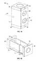
- FIG. 1Ais a perspective view of the first embodiment of the corpectomy cage according to the present invention.
- FIG. 1Bis a perspective view of the telescoping members of the first embodiment.
- FIG. 2is a sectional view taken along lines 2 - 2 of FIG. 1A .
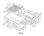
- FIG. 3is an exploded view of the telescoping members and sleeve of the corpectomy cage of the first embodiment.
- FIG. 3Ais an exploded view of an alternate embodiment with ratcheting side walls on the telescoping member.
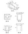
- FIG. 4is a plan view from one side of the cage.
- FIG. 5is a sectional view taken along lines 5 - 5 of FIG. 4 .
- FIG. 6is a perspective view of a shortened sleeve for the corpectomy cage.
- FIG. 7Ais a perspective view of the inner telescoping members.
- FIG. 7Bis an end view of the inner telescoping members shown in FIG. 7A .
- FIG. 7Cis an elevation view of one side of the inner telescoping member.
- FIG. 7Dis an end view from the opposite end of FIG. 7B .
- FIG. 7Eis another elevation view of the inner telescoping member.
- FIG. 8Ais a perspective view of the outer telescoping members.
- FIG. 8Bis an end view of the outer telescoping members shown in FIG. 8A .
- FIG. 8Cis an elevation view of one side of the outer telescoping member.
- FIG. 8Dis an end view from the opposite end of FIG. 8B .
- FIG. 8Eis another elevation view of the outer telescoping member.
- FIG. 9Ais a perspective view of the sleeve of the corpectomy cage.
- FIG. 9Bis a top plan view of the sleeve.
- FIG. 9Cis an elevation view from one side of the sleeve.
- FIG. 9Dis an elevation view from another side of the sleeve.
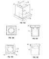
- FIG. 10is an exploded view of an alternative embodiment of the corpectomy cage.
- FIG. 11is a perspective view of a shortened sleeve for the cage of FIG. 10 .
- FIG. 12Ais a perspective view of the inner telescoping member of the corpectomy cage shown in FIG. 10 .
- FIG. 12Bis an end view of the inner telescoping members shown in FIG. 12A .
- FIG. 12Cis an elevation view of one side of the inner telescoping member shown in FIG. 12A .
- FIG. 12Dis an end view from the opposite end of FIG. 12B .
- FIG. 12Eis another elevation view of the inner telescoping member of FIG. 12A .
- FIG. 13Ais a perspective view of the outer telescoping member of the cage shown in FIG. 10 .
- FIG. 13Bis an end view of the outer telescoping members shown in FIG. 13A .
- FIG. 13Cis an elevation view of one side of the outer telescoping member shown in FIG. 13A .
- FIG. 13Dis an end view from the opposite end of FIG. 13B .
- FIG. 13Eis another elevation view of the outer telescoping member of FIG. 13A .
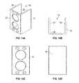
- FIG. 14Ais a perspective view of the sleeve of the corpectomy cage shown in FIG. 10 .
- FIG. 14Bis a top plan view of the sleeve of FIG. 14A .
- FIG. 14Cis an elevation view from one side of the sleeve shown in FIG. 14A .
- FIG. 14Dis an elevation view from another side of the sleeve of FIG. 14A .
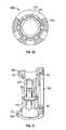
- FIG. 15is a perspective view of the round embodiment of the corpectomy cage of the present invention.
- FIG. 16is another perspective view of the round corpectomy cage.
- FIG. 17is an exploded view of the round corpectomy cage.
- FIG. 18is an enlarged view taken along line 18 of FIG. 16 .
- FIG. 19is a side elevation view of the round corpectomy cage.
- FIG. 20is a sectional view taken along lines 20 - 20 of FIG. 19 .
- FIG. 21is a sectional view taken along lines 21 - 21 of FIG. 19 .
- FIGS. 15-21show a round embodiment of the corpectomy cage designated by the reference numeral 10 A.
- the cage 10has three primary components: an inner telescoping member 12 , and outer telescoping member 14 and a sleeve or cover 16 .
- the cage 10 Ahas three primary components: an inner telescoping member 12 A, an outer telescoping member 14 A, and a sleeve or cover 16 A.
- the cages 10 and 10 A, and their components,function similarly to one another in implantation and in use.
- the inner telescoping member 12has opposite sides 18 with an inner connecting web or back wall 20 , with an opening 22 opposite the web 20 .
- the inner telescoping member 12has a general C-shape with squared corners.
- the outer telescoping member 14has opposite sides 24 , with an inner connecting web or back wall 26 , with an opening 28 opposite the web 26 .
- the outer telescoping member 14has a C-shape with squared corners.
- the sidewalls 18 of the member 12have a narrower spacing than the side walls 24 of the member 14 , such that the members 12 , 14 can be assembled for axial movement relative to one another.
- the sides 18have external ratchets 19 and the side 24 have internal ratchets.
- the ratchets 19 , 24matingly overlap and allow the telescoping members to be extended one step at a time, such as 1 mm increments.
- the inner and outer telescoping members 12 A, 14 Aeach have cylindrical side walls 18 A, 24 A, respectively, with enlarged openings therein.
- the diameter of member 12 Ais smaller than the diameter of member 14 A, so that the members can be assembled for axial movement relative to one another.
- the sleeve 16includes opposite sides 30 with a web or front wall 32 extending between the opposite sides, and an opening 34 opposite the web 32 .
- the sleeve 16has a C-shaped profile with squared corners.
- the sleeve 16 Ahas opposite sides 30 A with an opening 34 A.
- the inner and outer telescoping members 12 , 14each have an end plate 36 , 38 , respectively.
- the inner and outer round telescoping members 12 A, 14 Ahave respective end plates 36 A, 38 A.
- the inner and outer telescoping members 12 , 14 and 12 A, 14 Aare adapted to matingly and slidably fit together in a telescoping manner for axial expansion and retraction.
- the sleeve 16is adapted to matingly fit over the outer telescoping member 14 A, with the opposite ends of the sleeve 16 engaging the inner surfaces of the end plates 36 , 38 .
- the sleeve 16 Ais adapted to matingly fit over the outer telescoping member 14 A, with the ends of the sleeve 16 A abutting the inner surfaces of the end plates 36 A, 38 A.
- This assembly of the inner and outer telescoping members and the sleeveforms the cage 10 , 10 A with the sleeve 16 , 16 A being load bearing.
- the sleeves 16 , 16 Abear the axial loads from the vertebral bodies on the end plates 36 , 38 or 36 A, 38 A.
- the sleeves 16 , 16 Athereby preclude or prevent the telescoping members 12 , 14 and 12 A, 14 A from collapsing or retracting in vivo relative to one another.
- the sleeves 16 , 16 Aeliminate the need for a fastener between the inner and outer telescoping members, as in the prior art, to fix the relative positions of the telescoping members relative to one another.
- the telescoping members 12 , 14 and 12 A, 14 Aare non-load bearing.
- the inner and outer telescoping members 12 , 14have overlapping or interlocking structure so that these members slide axially without transverse separation. More particularly, in the preferred embodiment, the inner telescoping member 12 has an external tongue or lip 40 extending outwardly from each side 18 . The outer telescoping member has internal grooves 42 on each side 24 to slidably receive the tongues or lips 40 on the inner telescoping member 12 .
- the circular shapecontrols the sliding axial movement of the members relative to one another.
- the sleeve 16can be retained on the telescoping members 12 , 14 in any convenient manner.
- the sleeve 16snap fits onto the outer telescoping member 14 .
- the outer telescoping member 14has an axially extending external projection or bead 44 with a beveled surface and a retention shoulder extending along each side 24 .
- the sleeve 16has an internal groove 46 along the inside of each side wall 30 .
- the sides 30 of the sleeveare resilient such that the sleeve snap fits over the beads 44 , which are matingly received within the grooves 46 of the sleeve 16 .
- the sleeve 16is retained on the outer telescoping member 14 by the overlapping beads 44 and grooves 46 .
- the sleeve 16can be removed from the outer telescoping member 14 by spreading the sides 30 to disengage the beads 44 and grooves 46 .
- the sleeve 16is retained on the telescoping members 12 , 14 using screws 48 which extend through the sleeve and into threaded holes in the telescoping members 12 , 14 .
- the sides 30 A of the sleeve 16 Aare resilient, such that the sleeve 16 A can be snap fit over the telescoping members 12 A, 14 A.
- the sleeve 16 , 16 Ais generally selected by the surgeon performing the corpectomy from a set of sleeves having various heights or lengths, such that the assembled cage 10 , 10 A will properly fit between the upper and lower vertebral bodies.
- FIGS. 1-4show a longer or taller sleeve 16
- FIG. 6shows a shorter sleeve.
- FIG. 11shows a shorter sleeve compared to the longer sleeve shown in FIG. 14A .
- the sleeve 16 , 16 Aprevents the telescoping members 12 , 14 and 12 A, 14 A from being retracted toward one another
- the sleevecan prevent extension of the telescoping members relative to one another.
- the sleeve 16 Ahas a radially directed lip 50 extending inwardly from each end for receipt in a groove 42 on each telescoping member 12 A, 14 A.
- the lips 50 of the sleeve 16 Aare received in the grooves 52 of the telescoping members 12 A, 14 A to prevent the members from expanding axially.
- the cages 10 , 10 A of the present inventionare implanted using conventional methodology.
- the tips of a hand held expanding toolare received in holes 54 in the end plates 36 , 38 of the telescoping members 12 , 14 , or in a perimeter groove 56 in the end plates 36 A, 38 A of the telescoping members 12 A, 14 A.
- the sleeve 16 , 16 Ais placed over the telescoping members so as to fix the height of the cage 10 , 10 A.
- the axial loads on the cage 10 , 10 Aare then born by the sleeve 16 , 16 A, rather than by the telescoping members 12 , 14 and 12 A, 14 A.
- the cages 10 , 10 Ahave enlarged fusion openings 58 , 58 A to accommodate bone growth around and through the cage.
- the center cavity of the cageis substantially unobstructed for improved or enhanced bone growth and fusion.
- the telescoping segments 12 , 14 and 12 A, 14 A, as well as the sleeves 16 , 16 Acan be made of non-metallic material which does not interfere or otherwise produce artifacts when scanned or imaged.
- the cages 10 , 10 Acan be made of any high strength, lightweight, biocompatible material.
Landscapes
- Health & Medical Sciences (AREA)
- Engineering & Computer Science (AREA)
- Biomedical Technology (AREA)
- Neurology (AREA)
- Orthopedic Medicine & Surgery (AREA)
- Cardiology (AREA)
- Oral & Maxillofacial Surgery (AREA)
- Transplantation (AREA)
- Heart & Thoracic Surgery (AREA)
- Vascular Medicine (AREA)
- Life Sciences & Earth Sciences (AREA)
- Animal Behavior & Ethology (AREA)
- General Health & Medical Sciences (AREA)
- Public Health (AREA)
- Veterinary Medicine (AREA)
- Prostheses (AREA)
Abstract
Description
Claims (17)
Priority Applications (2)
| Application Number | Priority Date | Filing Date | Title |
|---|---|---|---|
| US13/409,357US9283086B2 (en) | 2011-03-03 | 2012-03-01 | Expandable corpectomy cage |
| US15/045,781US10004606B2 (en) | 2011-03-03 | 2016-02-17 | Expandable corpectomy cage |
Applications Claiming Priority (2)
| Application Number | Priority Date | Filing Date | Title |
|---|---|---|---|
| US201161448981P | 2011-03-03 | 2011-03-03 | |
| US13/409,357US9283086B2 (en) | 2011-03-03 | 2012-03-01 | Expandable corpectomy cage |
Related Child Applications (1)
| Application Number | Title | Priority Date | Filing Date |
|---|---|---|---|
| US15/045,781ContinuationUS10004606B2 (en) | 2011-03-03 | 2016-02-17 | Expandable corpectomy cage |
Publications (2)
| Publication Number | Publication Date |
|---|---|
| US20120226356A1 US20120226356A1 (en) | 2012-09-06 |
| US9283086B2true US9283086B2 (en) | 2016-03-15 |
Family
ID=46753778
Family Applications (2)
| Application Number | Title | Priority Date | Filing Date |
|---|---|---|---|
| US13/409,357Active2034-05-22US9283086B2 (en) | 2011-03-03 | 2012-03-01 | Expandable corpectomy cage |
| US15/045,781Active2032-06-02US10004606B2 (en) | 2011-03-03 | 2016-02-17 | Expandable corpectomy cage |
Family Applications After (1)
| Application Number | Title | Priority Date | Filing Date |
|---|---|---|---|
| US15/045,781Active2032-06-02US10004606B2 (en) | 2011-03-03 | 2016-02-17 | Expandable corpectomy cage |
Country Status (1)
| Country | Link |
|---|---|
| US (2) | US9283086B2 (en) |
Cited By (2)
| Publication number | Priority date | Publication date | Assignee | Title |
|---|---|---|---|---|
| US20190060081A1 (en)* | 2013-05-14 | 2019-02-28 | Expanding Innovations, Inc. | Intervertebral devices and related methods |
| US20240407926A1 (en)* | 2023-06-07 | 2024-12-12 | Biedermann Technologies Gmbh & Co. Kg | Implant for engagement between vertebrae, and implant kit |
Families Citing this family (22)
| Publication number | Priority date | Publication date | Assignee | Title |
|---|---|---|---|---|
| EP2547292B1 (en) | 2010-03-16 | 2019-04-24 | Pinnacle Spine Group, LLC | Ntervertebral implants and graft delivery systems |
| DE102010047901B4 (en)* | 2010-10-11 | 2019-01-10 | Heinrich Böhm | Implant for the spine and operating instrument |
| US9700425B1 (en) | 2011-03-20 | 2017-07-11 | Nuvasive, Inc. | Vertebral body replacement and insertion methods |
| US9468537B2 (en)* | 2011-06-21 | 2016-10-18 | Globus Medical, Inc. | Method and implant device for grafting adjacent vertebral bodies |
| US9380932B1 (en) | 2011-11-02 | 2016-07-05 | Pinnacle Spine Group, Llc | Retractor devices for minimally invasive access to the spine |
| WO2014159739A1 (en) | 2013-03-14 | 2014-10-02 | Pinnacle Spine Group, Llc | Interbody implants and graft delivery systems |
| ES2923640T3 (en)* | 2013-03-15 | 2022-09-29 | Spectrum Spine Ip Holdings Llc | Expandable Vertebral Body Replacement Device |
| WO2014145982A1 (en) | 2013-03-15 | 2014-09-18 | Spectrum Spine Ip Holdings, Llc | Expandable vertebral body replacement device, system, and methods |
| US9566167B2 (en) | 2013-08-22 | 2017-02-14 | K2M, Inc. | Expandable spinal implant |
| US9717605B2 (en) | 2014-06-03 | 2017-08-01 | Atlas Spine, Inc. | Spinal implant device |
| US10322011B2 (en) | 2014-06-03 | 2019-06-18 | Atlas Spine, Inc. | Spinal implant device with bone screws |
| US10034767B2 (en) | 2014-06-03 | 2018-07-31 | Atlas Spine, Inc. | Spinal implant device |
| US10610377B2 (en) | 2014-06-03 | 2020-04-07 | Atlas Spine, Inc. | Spinal implant device |
| US10010429B2 (en) | 2014-06-13 | 2018-07-03 | Facet-Link Inc. | Intervertebral cage which is expandable in steps and implantation instrument therefor |
| US10363142B2 (en) | 2014-12-11 | 2019-07-30 | K2M, Inc. | Expandable spinal implants |
| WO2016145165A1 (en)* | 2015-03-10 | 2016-09-15 | Atlas Spine, Inc. | Spinal implant device |
| US9839529B2 (en)* | 2015-05-18 | 2017-12-12 | Zavation Medical Products, Llc | Method and system of installing a spinal fusion cage |
| US10842651B2 (en)* | 2016-06-10 | 2020-11-24 | Globus Medical, Inc. | Vertebral implants and attachment assemblies |
| US10758365B2 (en) | 2017-05-08 | 2020-09-01 | Zavation Medical Products, Llc | Expandable spinal cage assemblies for supporting bone structures |
| US10441430B2 (en) | 2017-07-24 | 2019-10-15 | K2M, Inc. | Expandable spinal implants |
| US11135070B2 (en)* | 2018-02-14 | 2021-10-05 | Titan Spine, Inc. | Modular adjustable corpectomy cage |
| CN114795599A (en)* | 2022-04-28 | 2022-07-29 | 南京体医融合康复产业研究院有限公司 | Medical titanium cage with adjustable length and use method |
Citations (55)
| Publication number | Priority date | Publication date | Assignee | Title |
|---|---|---|---|---|
| US5059193A (en) | 1989-11-20 | 1991-10-22 | Spine-Tech, Inc. | Expandable spinal implant and surgical method |
| US5171278A (en) | 1991-02-22 | 1992-12-15 | Madhavan Pisharodi | Middle expandable intervertebral disk implants |
| US5236460A (en)* | 1990-02-12 | 1993-08-17 | Midas Rex Pneumatic Tools, Inc. | Vertebral body prosthesis |
| US5290312A (en) | 1991-09-03 | 1994-03-01 | Alphatec | Artificial vertebral body |
| US5336223A (en)* | 1993-02-04 | 1994-08-09 | Rogers Charles L | Telescoping spinal fixator |
| US5405391A (en)* | 1993-02-16 | 1995-04-11 | Hednerson; Fraser C. | Fusion stabilization chamber |
| US5458641A (en)* | 1993-09-08 | 1995-10-17 | Ramirez Jimenez; Juan J. | Vertebral body prosthesis |
| US5480442A (en)* | 1993-06-24 | 1996-01-02 | Man Ceramics Gmbh | Fixedly adjustable intervertebral prosthesis |
| US5514180A (en)* | 1994-01-14 | 1996-05-07 | Heggeness; Michael H. | Prosthetic intervertebral devices |
| US5702453A (en)* | 1994-12-09 | 1997-12-30 | Sofamor Danek Group | Adjustable vertebral body replacement |
| US5723013A (en)* | 1995-02-06 | 1998-03-03 | Jbs S.A. | Spacer implant for substituting missing vertebrae |
| US6066175A (en) | 1993-02-16 | 2000-05-23 | Henderson; Fraser C. | Fusion stabilization chamber |
| US6126689A (en) | 1998-06-15 | 2000-10-03 | Expanding Concepts, L.L.C. | Collapsible and expandable interbody fusion device |
| US6176881B1 (en)* | 1997-04-15 | 2001-01-23 | Synthes | Telescopic vertebral prosthesis |
| US6176882B1 (en) | 1998-02-20 | 2001-01-23 | Biedermann Motech Gmbh | Intervertebral implant |
| US6193756B1 (en)* | 1997-09-30 | 2001-02-27 | Sulzer Orthopaedie Ag | Tubular support body for bridging two vertebrae |
| US6200348B1 (en)* | 1998-02-06 | 2001-03-13 | Biedermann, Motech Gmbh | Spacer with adjustable axial length |
| US20010056302A1 (en)* | 2000-03-22 | 2001-12-27 | Boyer Michael L. | Skeletal reconstruction cages |
| US6375683B1 (en)* | 1997-05-02 | 2002-04-23 | Stryker France S.A. | Implant in particular for replacing a vertebral body in surgery of the spine |
| US20020161441A1 (en)* | 1998-10-15 | 2002-10-31 | Bruno Lang | Telescopic vertebral prosthesis |
| US20030083749A1 (en) | 2001-10-31 | 2003-05-01 | Kuslich Stephen D. | Corpectomy device |
| US20030181980A1 (en)* | 2002-03-21 | 2003-09-25 | Berry Bret M. | Vertebral body and disc space replacement devices |
| US20030191531A1 (en)* | 2002-03-21 | 2003-10-09 | Berry Bret M. | Vertebral body and disc space replacement devices |
| US6648891B2 (en) | 2001-09-14 | 2003-11-18 | The Regents Of The University Of California | System and method for fusing spinal vertebrae |
| US20030220643A1 (en)* | 2002-05-24 | 2003-11-27 | Ferree Bret A. | Devices to prevent spinal extension |
| US20040158250A1 (en) | 2002-09-13 | 2004-08-12 | Chappuis James L. | Anterior cervical corpectomy plate |
| US6866682B1 (en) | 1999-09-02 | 2005-03-15 | Stryker Spine | Distractable corpectomy device |
| US20060100710A1 (en)* | 2003-04-28 | 2006-05-11 | Michael Gutlin | Intervertebral implant |
| US7226481B2 (en) | 2000-07-21 | 2007-06-05 | Spineology, Inc. | Expandable porous mesh bag device and methods of use for reduction, filling, fixation, and supporting of bone |
| US20080046083A1 (en)* | 2006-08-15 | 2008-02-21 | Motionback Llc | Spinal implant |
| US20080058930A1 (en)* | 2006-07-21 | 2008-03-06 | Edie Jason A | Implant with nested members and methods of use |
| US7393361B2 (en)* | 2004-02-20 | 2008-07-01 | Spinecore, Inc. | Artificial intervertebral disc having a bored semispherical bearing with a compression locking post and retaining caps |
| US20080288071A1 (en) | 2006-05-16 | 2008-11-20 | Ashok Biyani | Expandable corpectomy device |
| US7458988B2 (en) | 2003-11-05 | 2008-12-02 | Warsaw Orthopedic, Inc. | Compressible corpectomy device |
| US20090118765A1 (en) | 2003-03-24 | 2009-05-07 | Richard Mueller | Expandable Corpectomy Device |
| US20090138083A1 (en) | 2006-09-14 | 2009-05-28 | Ashok Biyani | Variable height vertebral body replacement implant |
| US20090138089A1 (en) | 2007-11-27 | 2009-05-28 | Doubler Robert L | Corpectomy implant |
| US7544208B1 (en) | 2004-05-03 | 2009-06-09 | Theken Spine, Llc | Adjustable corpectomy apparatus |
| US20090164018A1 (en) | 2007-12-19 | 2009-06-25 | Robert Sommerich | Instruments For Expandable Corpectomy Spinal Fusion Cage |
| US7628800B2 (en) | 2005-06-03 | 2009-12-08 | Warsaw Orthopedic, Inc. | Formed in place corpectomy device |
| US20100030335A1 (en)* | 2008-01-25 | 2010-02-04 | Spinalmotion, Inc. | Compliant Implantable Prosthetic Joint With Preloaded Spring |
| US7674296B2 (en) | 2005-04-21 | 2010-03-09 | Globus Medical, Inc. | Expandable vertebral prosthesis |
| US20100179594A1 (en)* | 2008-03-28 | 2010-07-15 | Charles Theofilos | Expandable cage |
| US20100179656A1 (en) | 2008-03-28 | 2010-07-15 | Charles Theofilos | Expandable cage with locking device |
| US7758648B2 (en)* | 2006-04-27 | 2010-07-20 | Warsaw Orthopedic, Inc. | Stabilized, adjustable expandable implant and method |
| US7794501B2 (en) | 2006-04-27 | 2010-09-14 | Wasaw Orthopedic, Inc. | Expandable intervertebral spacers and methods of use |
| US7815683B2 (en) | 2006-10-16 | 2010-10-19 | Warsaw Orthopedic, Inc. | Implants with helical supports and methods of use for spacing vertebral members |
| US7824445B2 (en) | 1999-07-26 | 2010-11-02 | Ladislau Biro | Corpectomy vertebral body replacement implant system |
| US20100280616A1 (en) | 2009-04-29 | 2010-11-04 | William Frasier | Minimally invasive corpectomy cage and instrument |
| US7909870B2 (en)* | 2003-12-11 | 2011-03-22 | Tpl - Kilian Kraus | Height-adjustable spinal implant and operating instrument for the implant |
| US8062366B2 (en)* | 2007-01-08 | 2011-11-22 | Warsaw Orthopedic, Inc. | Ratcheting expandable corpectomy/vertebrectomy cage |
| US8187331B2 (en)* | 2006-04-27 | 2012-05-29 | Warsaw Orthopedic, Inc. | Expandable vertebral implant and methods of use |
| US8252054B2 (en)* | 2009-01-14 | 2012-08-28 | Stout Medical Group, L.P. | Expandable support device and method of use |
| US20130310938A1 (en)* | 2011-02-03 | 2013-11-21 | Medicrea International | Corporectomy implant |
| US8721723B2 (en)* | 2009-01-12 | 2014-05-13 | Globus Medical, Inc. | Expandable vertebral prosthesis |
Family Cites Families (2)
| Publication number | Priority date | Publication date | Assignee | Title |
|---|---|---|---|---|
| US7938858B2 (en) | 2003-09-15 | 2011-05-10 | Warsaw Orthopedic, Inc. | Spinal implant system |
| US8657882B2 (en) | 2006-04-24 | 2014-02-25 | Warsaw Orthopedic, Inc. | Expandable intervertebral devices and methods of use |
- 2012
- 2012-03-01USUS13/409,357patent/US9283086B2/enactiveActive
- 2016
- 2016-02-17USUS15/045,781patent/US10004606B2/enactiveActive
Patent Citations (55)
| Publication number | Priority date | Publication date | Assignee | Title |
|---|---|---|---|---|
| US5059193A (en) | 1989-11-20 | 1991-10-22 | Spine-Tech, Inc. | Expandable spinal implant and surgical method |
| US5236460A (en)* | 1990-02-12 | 1993-08-17 | Midas Rex Pneumatic Tools, Inc. | Vertebral body prosthesis |
| US5171278A (en) | 1991-02-22 | 1992-12-15 | Madhavan Pisharodi | Middle expandable intervertebral disk implants |
| US5290312A (en) | 1991-09-03 | 1994-03-01 | Alphatec | Artificial vertebral body |
| US5336223A (en)* | 1993-02-04 | 1994-08-09 | Rogers Charles L | Telescoping spinal fixator |
| US5405391A (en)* | 1993-02-16 | 1995-04-11 | Hednerson; Fraser C. | Fusion stabilization chamber |
| US6066175A (en) | 1993-02-16 | 2000-05-23 | Henderson; Fraser C. | Fusion stabilization chamber |
| US5480442A (en)* | 1993-06-24 | 1996-01-02 | Man Ceramics Gmbh | Fixedly adjustable intervertebral prosthesis |
| US5458641A (en)* | 1993-09-08 | 1995-10-17 | Ramirez Jimenez; Juan J. | Vertebral body prosthesis |
| US5514180A (en)* | 1994-01-14 | 1996-05-07 | Heggeness; Michael H. | Prosthetic intervertebral devices |
| US5702453A (en)* | 1994-12-09 | 1997-12-30 | Sofamor Danek Group | Adjustable vertebral body replacement |
| US5723013A (en)* | 1995-02-06 | 1998-03-03 | Jbs S.A. | Spacer implant for substituting missing vertebrae |
| US6176881B1 (en)* | 1997-04-15 | 2001-01-23 | Synthes | Telescopic vertebral prosthesis |
| US6375683B1 (en)* | 1997-05-02 | 2002-04-23 | Stryker France S.A. | Implant in particular for replacing a vertebral body in surgery of the spine |
| US6193756B1 (en)* | 1997-09-30 | 2001-02-27 | Sulzer Orthopaedie Ag | Tubular support body for bridging two vertebrae |
| US6200348B1 (en)* | 1998-02-06 | 2001-03-13 | Biedermann, Motech Gmbh | Spacer with adjustable axial length |
| US6176882B1 (en) | 1998-02-20 | 2001-01-23 | Biedermann Motech Gmbh | Intervertebral implant |
| US6126689A (en) | 1998-06-15 | 2000-10-03 | Expanding Concepts, L.L.C. | Collapsible and expandable interbody fusion device |
| US20020161441A1 (en)* | 1998-10-15 | 2002-10-31 | Bruno Lang | Telescopic vertebral prosthesis |
| US7824445B2 (en) | 1999-07-26 | 2010-11-02 | Ladislau Biro | Corpectomy vertebral body replacement implant system |
| US6866682B1 (en) | 1999-09-02 | 2005-03-15 | Stryker Spine | Distractable corpectomy device |
| US20010056302A1 (en)* | 2000-03-22 | 2001-12-27 | Boyer Michael L. | Skeletal reconstruction cages |
| US7226481B2 (en) | 2000-07-21 | 2007-06-05 | Spineology, Inc. | Expandable porous mesh bag device and methods of use for reduction, filling, fixation, and supporting of bone |
| US6648891B2 (en) | 2001-09-14 | 2003-11-18 | The Regents Of The University Of California | System and method for fusing spinal vertebrae |
| US20030083749A1 (en) | 2001-10-31 | 2003-05-01 | Kuslich Stephen D. | Corpectomy device |
| US20030181980A1 (en)* | 2002-03-21 | 2003-09-25 | Berry Bret M. | Vertebral body and disc space replacement devices |
| US20030191531A1 (en)* | 2002-03-21 | 2003-10-09 | Berry Bret M. | Vertebral body and disc space replacement devices |
| US20030220643A1 (en)* | 2002-05-24 | 2003-11-27 | Ferree Bret A. | Devices to prevent spinal extension |
| US20040158250A1 (en) | 2002-09-13 | 2004-08-12 | Chappuis James L. | Anterior cervical corpectomy plate |
| US20090118765A1 (en) | 2003-03-24 | 2009-05-07 | Richard Mueller | Expandable Corpectomy Device |
| US20060100710A1 (en)* | 2003-04-28 | 2006-05-11 | Michael Gutlin | Intervertebral implant |
| US7458988B2 (en) | 2003-11-05 | 2008-12-02 | Warsaw Orthopedic, Inc. | Compressible corpectomy device |
| US7909870B2 (en)* | 2003-12-11 | 2011-03-22 | Tpl - Kilian Kraus | Height-adjustable spinal implant and operating instrument for the implant |
| US7393361B2 (en)* | 2004-02-20 | 2008-07-01 | Spinecore, Inc. | Artificial intervertebral disc having a bored semispherical bearing with a compression locking post and retaining caps |
| US7544208B1 (en) | 2004-05-03 | 2009-06-09 | Theken Spine, Llc | Adjustable corpectomy apparatus |
| US7674296B2 (en) | 2005-04-21 | 2010-03-09 | Globus Medical, Inc. | Expandable vertebral prosthesis |
| US7628800B2 (en) | 2005-06-03 | 2009-12-08 | Warsaw Orthopedic, Inc. | Formed in place corpectomy device |
| US8187331B2 (en)* | 2006-04-27 | 2012-05-29 | Warsaw Orthopedic, Inc. | Expandable vertebral implant and methods of use |
| US7758648B2 (en)* | 2006-04-27 | 2010-07-20 | Warsaw Orthopedic, Inc. | Stabilized, adjustable expandable implant and method |
| US7794501B2 (en) | 2006-04-27 | 2010-09-14 | Wasaw Orthopedic, Inc. | Expandable intervertebral spacers and methods of use |
| US20080288071A1 (en) | 2006-05-16 | 2008-11-20 | Ashok Biyani | Expandable corpectomy device |
| US20080058930A1 (en)* | 2006-07-21 | 2008-03-06 | Edie Jason A | Implant with nested members and methods of use |
| US20080046083A1 (en)* | 2006-08-15 | 2008-02-21 | Motionback Llc | Spinal implant |
| US20090138083A1 (en) | 2006-09-14 | 2009-05-28 | Ashok Biyani | Variable height vertebral body replacement implant |
| US7815683B2 (en) | 2006-10-16 | 2010-10-19 | Warsaw Orthopedic, Inc. | Implants with helical supports and methods of use for spacing vertebral members |
| US8062366B2 (en)* | 2007-01-08 | 2011-11-22 | Warsaw Orthopedic, Inc. | Ratcheting expandable corpectomy/vertebrectomy cage |
| US20090138089A1 (en) | 2007-11-27 | 2009-05-28 | Doubler Robert L | Corpectomy implant |
| US20090164018A1 (en) | 2007-12-19 | 2009-06-25 | Robert Sommerich | Instruments For Expandable Corpectomy Spinal Fusion Cage |
| US20100030335A1 (en)* | 2008-01-25 | 2010-02-04 | Spinalmotion, Inc. | Compliant Implantable Prosthetic Joint With Preloaded Spring |
| US20100179656A1 (en) | 2008-03-28 | 2010-07-15 | Charles Theofilos | Expandable cage with locking device |
| US20100179594A1 (en)* | 2008-03-28 | 2010-07-15 | Charles Theofilos | Expandable cage |
| US8721723B2 (en)* | 2009-01-12 | 2014-05-13 | Globus Medical, Inc. | Expandable vertebral prosthesis |
| US8252054B2 (en)* | 2009-01-14 | 2012-08-28 | Stout Medical Group, L.P. | Expandable support device and method of use |
| US20100280616A1 (en) | 2009-04-29 | 2010-11-04 | William Frasier | Minimally invasive corpectomy cage and instrument |
| US20130310938A1 (en)* | 2011-02-03 | 2013-11-21 | Medicrea International | Corporectomy implant |
Cited By (4)
| Publication number | Priority date | Publication date | Assignee | Title |
|---|---|---|---|---|
| US20190060081A1 (en)* | 2013-05-14 | 2019-02-28 | Expanding Innovations, Inc. | Intervertebral devices and related methods |
| US11602441B2 (en)* | 2013-05-14 | 2023-03-14 | Expanding Innovations, Inc. | Intervertebral devices and related methods |
| US20240407926A1 (en)* | 2023-06-07 | 2024-12-12 | Biedermann Technologies Gmbh & Co. Kg | Implant for engagement between vertebrae, and implant kit |
| US12396864B2 (en)* | 2023-06-07 | 2025-08-26 | Biedermann Technologies Gmbh & Co. Kg | Implant for engagement between vertebrae, and implant kit |
Also Published As
| Publication number | Publication date |
|---|---|
| US10004606B2 (en) | 2018-06-26 |
| US20160242922A1 (en) | 2016-08-25 |
| US20120226356A1 (en) | 2012-09-06 |
Similar Documents
| Publication | Publication Date | Title |
|---|---|---|
| US10004606B2 (en) | Expandable corpectomy cage | |
| US10842643B2 (en) | Unidirectional dynamic interbody fusion device and method of use | |
| US12329657B2 (en) | Expandable intervertebral spacers | |
| US20210369468A1 (en) | Multiple spindle adjustable interbody fusion devices and methods of use | |
| US10667925B2 (en) | Adjustable interbody fusion device and method of use | |
| US8152852B2 (en) | Variable height vertebral body replacement implant | |
| US8187331B2 (en) | Expandable vertebral implant and methods of use | |
| US8197546B2 (en) | Corpectomy implant | |
| US9610169B2 (en) | Vertebral implants and methods for installation thereof | |
| US8377140B2 (en) | Expandable spinal implant device | |
| JP6678161B2 (en) | Spinal implant | |
| CA2347472C (en) | Telescopic vertebral prosthesis | |
| US9023107B2 (en) | Vertebral body replacement | |
| HK1223527A1 (en) | Staged, bilaterally expandable trial | |
| WO2009023016A1 (en) | Expandable vertebral implant and methods of use |
Legal Events
| Date | Code | Title | Description |
|---|---|---|---|
| AS | Assignment | Owner name:LANX, INC., COLORADO Free format text:ASSIGNMENT OF ASSIGNORS INTEREST;ASSIGNOR:HIRSCHL, ROBERT ALEX, M.D.;REEL/FRAME:029502/0537 Effective date:20121022 | |
| AS | Assignment | Owner name:BANK OF AMERICA, N.A., AS ADMINISTRATIVE AGENT, NORTH CAROLINA Free format text:SECURITY AGREEMENT;ASSIGNOR:LANX, INC.;REEL/FRAME:032086/0664 Effective date:20140113 Owner name:BANK OF AMERICA, N.A., AS ADMINISTRATIVE AGENT, NO Free format text:SECURITY AGREEMENT;ASSIGNOR:LANX, INC.;REEL/FRAME:032086/0664 Effective date:20140113 | |
| AS | Assignment | Owner name:HIRSCHL, ROBERT ALEX, IOWA Free format text:ASSIGNMENT OF ASSIGNORS INTEREST;ASSIGNOR:LANX, INC.;REEL/FRAME:034290/0273 Effective date:20140623 Owner name:LIFE SPINE, INC., ILLINOIS Free format text:ASSIGNMENT OF ASSIGNORS INTEREST;ASSIGNOR:HIRSCHL, ROBERT;REEL/FRAME:034501/0306 Effective date:20140612 | |
| AS | Assignment | Owner name:LANX, INC., COLORADO Free format text:RELEASE BY SECURED PARTY;ASSIGNOR:BANK OF AMERICA, N.A.;REEL/FRAME:034646/0992 Effective date:20150106 | |
| AS | Assignment | Owner name:LANX, INC., COLORADO Free format text:RELEASE OF SECURITY INTEREST IN PATENTS RECORDED AT REEL 032086/ FRAME 0664;ASSIGNOR:BANK OF AMERICA, N.A., AS ADMINISTRATIVE AGENT;REEL/FRAME:037155/0041 Effective date:20150624 | |
| STCF | Information on status: patent grant | Free format text:PATENTED CASE | |
| AS | Assignment | Owner name:MB FINANCIAL BANK, N.A., ILLINOIS Free format text:SECURITY INTEREST;ASSIGNORS:LIFE SPINE, INC.;GIZMO MEDICAL, LLC;REEL/FRAME:040491/0791 Effective date:20161025 Owner name:ST CLOUD CAPITAL PARTNERS III SBIC, LP, CALIFORNIA Free format text:SECURITY INTEREST;ASSIGNORS:GIZMO MEDICAL, LLC;LIFE SPINE, INC.;REEL/FRAME:040497/0926 Effective date:20161025 | |
| AS | Assignment | Owner name:LIFE SPINE, INC., ILLINOIS Free format text:RELEASE BY SECURED PARTY;ASSIGNOR:BMO HARRIS BANK N.A.;REEL/FRAME:040511/0788 Effective date:20161028 | |
| AS | Assignment | Owner name:ST CLOUD CAPITAL PARTNERS III SBIC, LP, CALIFORNIA Free format text:CORRECTIVE ASSIGNMENT TO CORRECT THE LEGAL DOCUMENT ATTACHED TO THE FILING PREVIOUSLY RECORDED AT REEL: 040497 FRAME: 0926. ASSIGNOR(S) HEREBY CONFIRMS THE SECURITY INTEREST;ASSIGNORS:GIZMO MEDIACL, LLC;LIFE SPINE, INC.;REEL/FRAME:042084/0917 Effective date:20161025 Owner name:ST CLOUD CAPITAL PARTNERS III SBIC, LP, CALIFORNIA Free format text:CORRECTIVE ASSIGNMENT TO CORRECT THE LEGAL DOCUMENT PREVIOUSLY RECORDED AT REEL: 040497 FRAME: 0926. ASSIGNOR(S) HEREBY CONFIRMS THE ASSIGNMENT;ASSIGNORS:GIZMO MEDICAL, LLC;LIFE SPINE, INC.;REEL/FRAME:042243/0607 Effective date:20161025 | |
| FEPP | Fee payment procedure | Free format text:MAINTENANCE FEE REMINDER MAILED (ORIGINAL EVENT CODE: REM.); ENTITY STATUS OF PATENT OWNER: SMALL ENTITY | |
| FEPP | Fee payment procedure | Free format text:SURCHARGE FOR LATE PAYMENT, SMALL ENTITY (ORIGINAL EVENT CODE: M2554); ENTITY STATUS OF PATENT OWNER: SMALL ENTITY | |
| MAFP | Maintenance fee payment | Free format text:PAYMENT OF MAINTENANCE FEE, 4TH YR, SMALL ENTITY (ORIGINAL EVENT CODE: M2551); ENTITY STATUS OF PATENT OWNER: SMALL ENTITY Year of fee payment:4 | |
| AS | Assignment | Owner name:GIZMO MEDICAL, LLC, ILLINOIS Free format text:RELEASE BY SECURED PARTY;ASSIGNOR:FIFTH THIRD BANK, NATIONAL ASSOCIATION;REEL/FRAME:054843/0755 Effective date:20201218 Owner name:LIFE SPINE, INC., ILLINOIS Free format text:RELEASE BY SECURED PARTY;ASSIGNOR:FIFTH THIRD BANK, NATIONAL ASSOCIATION;REEL/FRAME:054843/0755 Effective date:20201218 Owner name:ST. CLOUD CAPITAL PARTNERS III SBIC, LP, CALIFORNIA Free format text:SECURITY INTEREST;ASSIGNORS:LIFE SPINE, INC.;GIZMO MEDICAL, LLC;REEL/FRAME:054844/0239 Effective date:20201218 | |
| AS | Assignment | Owner name:ASSOCIATED BANK, NATIONAL ASSOCIATION, AS AGENT, ILLINOIS Free format text:SECURITY INTEREST;ASSIGNOR:LIFE SPINE, INC.;REEL/FRAME:056728/0438 Effective date:20210630 | |
| AS | Assignment | Owner name:LIFE SPINE, INC., ILLINOIS Free format text:RELEASE BY SECURED PARTY;ASSIGNOR:ASSOCIATED BANK, NATIONAL ASSOCIATION;REEL/FRAME:064275/0446 Effective date:20230526 | |
| FEPP | Fee payment procedure | Free format text:MAINTENANCE FEE REMINDER MAILED (ORIGINAL EVENT CODE: REM.); ENTITY STATUS OF PATENT OWNER: SMALL ENTITY | |
| FEPP | Fee payment procedure | Free format text:7.5 YR SURCHARGE - LATE PMT W/IN 6 MO, SMALL ENTITY (ORIGINAL EVENT CODE: M2555); ENTITY STATUS OF PATENT OWNER: SMALL ENTITY | |
| MAFP | Maintenance fee payment | Free format text:PAYMENT OF MAINTENANCE FEE, 8TH YR, SMALL ENTITY (ORIGINAL EVENT CODE: M2552); ENTITY STATUS OF PATENT OWNER: SMALL ENTITY Year of fee payment:8 |