US9283031B2 - Ablation apparatus and system to limit nerve conduction - Google Patents
Ablation apparatus and system to limit nerve conductionDownload PDFInfo
- Publication number
- US9283031B2 US9283031B2US12/612,360US61236009AUS9283031B2US 9283031 B2US9283031 B2US 9283031B2US 61236009 AUS61236009 AUS 61236009AUS 9283031 B2US9283031 B2US 9283031B2
- Authority
- US
- United States
- Prior art keywords
- probe
- nerve
- ablation
- electrode
- energy
- Prior art date
- Legal status (The legal status is an assumption and is not a legal conclusion. Google has not performed a legal analysis and makes no representation as to the accuracy of the status listed.)
- Expired - Fee Related, expires
Links
Images


Classifications
- A—HUMAN NECESSITIES
- A61—MEDICAL OR VETERINARY SCIENCE; HYGIENE
- A61B—DIAGNOSIS; SURGERY; IDENTIFICATION
- A61B18/00—Surgical instruments, devices or methods for transferring non-mechanical forms of energy to or from the body
- A61B18/04—Surgical instruments, devices or methods for transferring non-mechanical forms of energy to or from the body by heating
- A61B18/12—Surgical instruments, devices or methods for transferring non-mechanical forms of energy to or from the body by heating by passing a current through the tissue to be heated, e.g. high-frequency current
- A61B18/14—Probes or electrodes therefor
- A61B18/1477—Needle-like probes
- A—HUMAN NECESSITIES
- A61—MEDICAL OR VETERINARY SCIENCE; HYGIENE
- A61B—DIAGNOSIS; SURGERY; IDENTIFICATION
- A61B18/00—Surgical instruments, devices or methods for transferring non-mechanical forms of energy to or from the body
- A61B18/04—Surgical instruments, devices or methods for transferring non-mechanical forms of energy to or from the body by heating
- A61B18/12—Surgical instruments, devices or methods for transferring non-mechanical forms of energy to or from the body by heating by passing a current through the tissue to be heated, e.g. high-frequency current
- A61B18/14—Probes or electrodes therefor
- A—HUMAN NECESSITIES
- A61—MEDICAL OR VETERINARY SCIENCE; HYGIENE
- A61B—DIAGNOSIS; SURGERY; IDENTIFICATION
- A61B18/00—Surgical instruments, devices or methods for transferring non-mechanical forms of energy to or from the body
- A61B18/04—Surgical instruments, devices or methods for transferring non-mechanical forms of energy to or from the body by heating
- A61B18/12—Surgical instruments, devices or methods for transferring non-mechanical forms of energy to or from the body by heating by passing a current through the tissue to be heated, e.g. high-frequency current
- A61B18/1206—Generators therefor
- A—HUMAN NECESSITIES
- A61—MEDICAL OR VETERINARY SCIENCE; HYGIENE
- A61B—DIAGNOSIS; SURGERY; IDENTIFICATION
- A61B18/00—Surgical instruments, devices or methods for transferring non-mechanical forms of energy to or from the body
- A61B18/04—Surgical instruments, devices or methods for transferring non-mechanical forms of energy to or from the body by heating
- A61B18/12—Surgical instruments, devices or methods for transferring non-mechanical forms of energy to or from the body by heating by passing a current through the tissue to be heated, e.g. high-frequency current
- A61B18/14—Probes or electrodes therefor
- A61B18/16—Indifferent or passive electrodes for grounding
- A—HUMAN NECESSITIES
- A61—MEDICAL OR VETERINARY SCIENCE; HYGIENE
- A61B—DIAGNOSIS; SURGERY; IDENTIFICATION
- A61B90/00—Instruments, implements or accessories specially adapted for surgery or diagnosis and not covered by any of the groups A61B1/00 - A61B50/00, e.g. for luxation treatment or for protecting wound edges
- A61B90/30—Devices for illuminating a surgical field, the devices having an interrelation with other surgical devices or with a surgical procedure
- G—PHYSICS
- G06—COMPUTING OR CALCULATING; COUNTING
- G06F—ELECTRIC DIGITAL DATA PROCESSING
- G06F13/00—Interconnection of, or transfer of information or other signals between, memories, input/output devices or central processing units
- H—ELECTRICITY
- H04—ELECTRIC COMMUNICATION TECHNIQUE
- H04N—PICTORIAL COMMUNICATION, e.g. TELEVISION
- H04N5/00—Details of television systems
- H04N5/44—Receiver circuitry for the reception of television signals according to analogue transmission standards
- H04N5/455—Demodulation-circuits
- A61B19/5202—
- A61B19/5244—
- A—HUMAN NECESSITIES
- A61—MEDICAL OR VETERINARY SCIENCE; HYGIENE
- A61B—DIAGNOSIS; SURGERY; IDENTIFICATION
- A61B17/00—Surgical instruments, devices or methods
- A61B2017/00477—Coupling
- A61B2017/00482—Coupling with a code
- A—HUMAN NECESSITIES
- A61—MEDICAL OR VETERINARY SCIENCE; HYGIENE
- A61B—DIAGNOSIS; SURGERY; IDENTIFICATION
- A61B18/00—Surgical instruments, devices or methods for transferring non-mechanical forms of energy to or from the body
- A61B2018/00315—Surgical instruments, devices or methods for transferring non-mechanical forms of energy to or from the body for treatment of particular body parts
- A61B2018/00434—Neural system
- A—HUMAN NECESSITIES
- A61—MEDICAL OR VETERINARY SCIENCE; HYGIENE
- A61B—DIAGNOSIS; SURGERY; IDENTIFICATION
- A61B18/00—Surgical instruments, devices or methods for transferring non-mechanical forms of energy to or from the body
- A61B2018/00571—Surgical instruments, devices or methods for transferring non-mechanical forms of energy to or from the body for achieving a particular surgical effect
- A61B2018/00577—Ablation
- A—HUMAN NECESSITIES
- A61—MEDICAL OR VETERINARY SCIENCE; HYGIENE
- A61B—DIAGNOSIS; SURGERY; IDENTIFICATION
- A61B18/00—Surgical instruments, devices or methods for transferring non-mechanical forms of energy to or from the body
- A61B2018/00636—Sensing and controlling the application of energy
- A61B2018/00696—Controlled or regulated parameters
- A61B2018/00702—Power or energy
- A—HUMAN NECESSITIES
- A61—MEDICAL OR VETERINARY SCIENCE; HYGIENE
- A61B—DIAGNOSIS; SURGERY; IDENTIFICATION
- A61B18/00—Surgical instruments, devices or methods for transferring non-mechanical forms of energy to or from the body
- A61B2018/00636—Sensing and controlling the application of energy
- A61B2018/00696—Controlled or regulated parameters
- A61B2018/0072—Current
- A—HUMAN NECESSITIES
- A61—MEDICAL OR VETERINARY SCIENCE; HYGIENE
- A61B—DIAGNOSIS; SURGERY; IDENTIFICATION
- A61B18/00—Surgical instruments, devices or methods for transferring non-mechanical forms of energy to or from the body
- A61B2018/00636—Sensing and controlling the application of energy
- A61B2018/00696—Controlled or regulated parameters
- A61B2018/00732—Frequency
- A—HUMAN NECESSITIES
- A61—MEDICAL OR VETERINARY SCIENCE; HYGIENE
- A61B—DIAGNOSIS; SURGERY; IDENTIFICATION
- A61B18/00—Surgical instruments, devices or methods for transferring non-mechanical forms of energy to or from the body
- A61B2018/00636—Sensing and controlling the application of energy
- A61B2018/00696—Controlled or regulated parameters
- A61B2018/00761—Duration
- A—HUMAN NECESSITIES
- A61—MEDICAL OR VETERINARY SCIENCE; HYGIENE
- A61B—DIAGNOSIS; SURGERY; IDENTIFICATION
- A61B18/00—Surgical instruments, devices or methods for transferring non-mechanical forms of energy to or from the body
- A61B2018/00988—Means for storing information, e.g. calibration constants, or for preventing excessive use, e.g. usage, service life counter
- A—HUMAN NECESSITIES
- A61—MEDICAL OR VETERINARY SCIENCE; HYGIENE
- A61B—DIAGNOSIS; SURGERY; IDENTIFICATION
- A61B18/00—Surgical instruments, devices or methods for transferring non-mechanical forms of energy to or from the body
- A61B18/04—Surgical instruments, devices or methods for transferring non-mechanical forms of energy to or from the body by heating
- A61B18/12—Surgical instruments, devices or methods for transferring non-mechanical forms of energy to or from the body by heating by passing a current through the tissue to be heated, e.g. high-frequency current
- A61B18/14—Probes or electrodes therefor
- A61B2018/1467—Probes or electrodes therefor using more than two electrodes on a single probe
- A—HUMAN NECESSITIES
- A61—MEDICAL OR VETERINARY SCIENCE; HYGIENE
- A61B—DIAGNOSIS; SURGERY; IDENTIFICATION
- A61B18/00—Surgical instruments, devices or methods for transferring non-mechanical forms of energy to or from the body
- A61B18/04—Surgical instruments, devices or methods for transferring non-mechanical forms of energy to or from the body by heating
- A61B18/12—Surgical instruments, devices or methods for transferring non-mechanical forms of energy to or from the body by heating by passing a current through the tissue to be heated, e.g. high-frequency current
- A61B18/14—Probes or electrodes therefor
- A61B18/16—Indifferent or passive electrodes for grounding
- A61B2018/162—Indifferent or passive electrodes for grounding located on the probe body
- A61B2019/4815—
- A61B2019/4873—
- A61B2019/5437—
- A—HUMAN NECESSITIES
- A61—MEDICAL OR VETERINARY SCIENCE; HYGIENE
- A61B—DIAGNOSIS; SURGERY; IDENTIFICATION
- A61B90/00—Instruments, implements or accessories specially adapted for surgery or diagnosis and not covered by any of the groups A61B1/00 - A61B50/00, e.g. for luxation treatment or for protecting wound edges
- A61B90/08—Accessories or related features not otherwise provided for
- A61B2090/0803—Counting the number of times an instrument is used
- A—HUMAN NECESSITIES
- A61—MEDICAL OR VETERINARY SCIENCE; HYGIENE
- A61B—DIAGNOSIS; SURGERY; IDENTIFICATION
- A61B90/00—Instruments, implements or accessories specially adapted for surgery or diagnosis and not covered by any of the groups A61B1/00 - A61B50/00, e.g. for luxation treatment or for protecting wound edges
- A61B90/08—Accessories or related features not otherwise provided for
- A61B2090/0814—Preventing re-use
- A—HUMAN NECESSITIES
- A61—MEDICAL OR VETERINARY SCIENCE; HYGIENE
- A61B—DIAGNOSIS; SURGERY; IDENTIFICATION
- A61B90/00—Instruments, implements or accessories specially adapted for surgery or diagnosis and not covered by any of the groups A61B1/00 - A61B50/00, e.g. for luxation treatment or for protecting wound edges
- A61B90/39—Markers, e.g. radio-opaque or breast lesions markers
- A61B2090/3937—Visible markers
- A—HUMAN NECESSITIES
- A61—MEDICAL OR VETERINARY SCIENCE; HYGIENE
- A61B—DIAGNOSIS; SURGERY; IDENTIFICATION
- A61B34/00—Computer-aided surgery; Manipulators or robots specially adapted for use in surgery
- A61B34/20—Surgical navigation systems; Devices for tracking or guiding surgical instruments, e.g. for frameless stereotaxis
Definitions
- the present inventionrelates to a method and device used in the field of Minimally Invasive Surgery (or MIS) for interrupting the flow of signals through nerves. These nerves may be rendered incapable of transmitting signals either on a temporarily (hours, days or weeks) or a permanent (months or years) basis.
- One embodiment of the apparatusincludes a single puncture system which features electrodes capable of creating areas of nerve destruction, inhibition and ablation.
- the human nervous systemis used to send and receive signals.
- the pathway taken by the nerve signalsconveys sensory information such as pain, heat, cold and touch and command signals which cause movement (e.g. muscle contractions).
- nervesOften extraneous, undesired, or abnormal signals are generated (or are transmitted) along nervous system pathways. Examples include, but are not limited to, the pinching of a minor nerve in the back, which causes extreme back pain. Similarly, the compression or other activation of certain nerves may cause referred pain. Certain diseases also may compromise the lining of nerves such that signals are spontaneously generated, which can cause a variety of maladies, from seizures to pain or (in extreme conditions) even death. Abnormal signal activations can cause many other problems including (but not limited to) twitching, tics, seizures, distortions, cramps, disabilities (in addition to pain), other undesirable conditions, or other painful, abnormal, undesirable, socially or physically detrimental afflictions.
- the normal conduction of nerve signalscan cause undesirable effects.
- the activation of the corrugator supercilli musclecauses frown lines which may result in permanent distortion of the brow (or forehead); giving the appearance of premature aging.
- this phenomenonmay be terminated.
- Direct surgical interruption of nervesis however a difficult procedure.
- a unipolar electrode systemincludes a small surface area electrode, and a return electrode.
- the return electrodeis generally larger in size, and is either resistively or capacitively coupled to the body. Since the same amount of current must flow through each electrode to complete the circuit; the heat generated in the return electrode is dissipated over a larger surface area, and whenever possible, the return electrode is located in areas of high blood flow (such as the biceps, buttocks or other muscular or highly vascularized area) so that heat generated is rapidly carried away, thus preventing a heat rise and consequent burns of the tissue.
- a unipolar systemis the ability to place the unipolar probe exactly where it is needed and optimally focus electrosurgical energy where desired.
- One disadvantage of a unipolar systemis that the return electrode must be properly placed and in contact throughout the procedure. A resistive return electrode would typically be coated with a conductive paste or jelly. If the contact with the patient is reduced or if the jelly dries out, a high-current density area may result, increasing the probability for burns at the contact point.
- Typical bipolar electrode systemsare generally based upon a dual surface device (such as forceps, tweezers, pliers and other grasping type instruments) where the two separate surfaces can be brought together mechanically under force. Each opposing surface is connected to one of the two source connections of the electrosurgical generator. Subsequently, the desired object is held and compressed between the two surfaces. When the electrosurgical energy is applied, it is concentrated (and focused) so that tissue can be cut, desiccated, burned, killed, stunned, closed, destroyed or sealed between the grasping surfaces. Assuming the instrument has been designed and used properly, the resulting current flow will be constrained within the target tissue between the two surfaces.
- One disadvantage of a conventional bipolar systemis that the target tissue must be properly located and isolated between these surfaces.
- the electrodescan not make contact with other tissue, which often requires visual guidance (such as direct visualization, use of a scope, ultrasound or other direct visualization methods) so that the target tissue is properly contained within the bipolar electrodes themselves, prior to application of electrical energy.
- RF ablationdelivers electrical energy in either a bipolar or unipolar configuration utilizing a long catheter, similar to an electrophysiology (EP) catheter.
- An EP catheterconsisting of a long system of wires and supporting structures normally introduced via an artery or vein which leads into the heart is manipulated using various guidance techniques, such as measurement of electrical activity, ultrasonic guidance, and/or X-ray visualization, into the target area. Electrical energy is then applied and the target tissue is destroyed.
- U.S. Pat. No. 5,397,339issued Mar. 14, 1995, describes a multipolar electrode catheter, which can be used to stimulate, ablate, obtain intercardiac signals, and can expand and enlarge itself inside the heart.
- Other applicationsinclude the ability to destroy plaque formations in the interior of lumens within the body; using RF energy applied near, or at the tip of, catheters such as described in U.S. Pat. No. 5,454,809 and U.S. Pat. No. 5,749,914.
- a more advanced catheterwhich is similar to the EP catheters described above contains an array of electrodes that are able to selectively apply energy in a specific direction.
- U.S. Pat. No. 5,098,431discloses another catheter based system for removing obstructions from within blood vessels.
- Parins, in U.S. Pat. No. 5,078,717discloses yet another catheter to selectively remove stenotic lesions from the interior walls of blood vessels.
- Auth in U.S. Pat. No. 5,364,393describes a modification of the above technologies whereby a small guide wire which goes through an angioplasty device and is typically 110 cm or longer has an electrically energized tip, which creates a path to follow and thus guides itself through the obstructions.
- catheterswhich carry larger energy bursts, for example from a defibrillator into chambers of the heart have been disclosed. These catheters are used to destroy both tissues and structures as described in Cunningham (U.S. Pat. No. 4,896,671).
- Botulinum toxinbotulinum toxin
- the cardiac ablation fieldhas included stimulation by using either unipolar and bipolar energy by means of a test pacemaker pulse prior to the implantation of a pacemaker or other stimulation device.
- a method of threshold analysiscalled the ‘strength duration curve’ has been used for many years. This curve consists of a vertical axis (or Y-axis) typically voltage, current, charge or other measure of amplitude, and has a horizontal axis (or X-axis) of pulse duration (typically in milliseconds). Such a curve is a rapidly declining line, which decreases exponentially as the pulse width is increased.
- One aspect of the present inventionis an electrosurgical probe including a probe body which defines a longitudinal probe axis. Thus the probe resembles a single needle and can be placed into tissue through a single opening.
- the electrosurgical probealso includes a first and second conductive electrode, each disposed along the probe axis.
- the surface area of the first conductive electrodeis, in this aspect of the invention, greater than the surface area of the second conductive electrode.
- the ratio of the surface area of the first conductive electrode to the surface area of the second conductive electrodemay be equal to or greater than 3:1 or equal to or greater than 8:1.
- the ratio of the surface area of the first conductive electrode to the surface area of the second conductive electrodemay be adjustable.
- the electrosurgical probe of the subject inventionmay further include a stimulation energy source in electrical communication with either the first or the second conductive electrode.
- the electrosurgical probemay also include an ablation energy source communicating with either the first or second conductive electrode.
- a switchmay be provided for the selective connection of the stimulation energy source or the ablation energy source to at least one of the conductive electrodes. Either the first or the second conductive electrode may be nearer the point of the electrosurgical probe at one end of the probe axis.
- an electrosurgical probeincluding a probe body defining a longitudinal probe axis, an active electrode operatively associated with the probe body at a first location along the probe axis, a stimulation electrode associated with the probe body at a second location along the probe axis and a return electrode operatively associated with the probe body at a third location along the probe axis.
- the stimulation electrodemay be positioned between the active and return electrodes.
- the electrosurgical probe of this embodimentmay further include a stimulation energy source in electrical communication with the stimulation electrode.
- the stimulation energy sourcemay provide variable stimulation current. Either the active electrode, the return electrode or both may be connected to a ground for the stimulation energy source. Alternatively, a separate ground may be employed.
- This aspect of the present inventionmay also include an ablation energy source connected to the active electrode.
- the ablation energy sourcemay be configured to provide variable ablation energy.
- an electrosurgical probealso having a probe body defining a longitudinal probe axis. At least three electrodes will be associated with the probe body at distinct and separate locations along the probe axis. A stimulation energy source connected to at least one of the electrodes is also included.
- the stimulation energy source of this embodiment of the present inventionmay be configured to provide variable stimulation energy.
- the stimulation energy sourcemay be selectively connected by means of a switch to at least one or more of the various electrodes.
- a ground for the stimulation energy sourcemay be selectively connected to one or more of the electrodes.
- Another aspect of the present inventionis a method for positioning an electrosurgical probe.
- the methodincludes providing an electrosurgical probe such as those described immediately above, inserting the electrical surgical probe to a first position within tissue containing a target nerve and applying stimulation energy to an electrode. Upon the application of stimulation energy, a first response of a muscle associated with the target nerve may be observed. Thereupon, the electrosurgical probe may be moved to a second position and a second application of stimulation energy may be undertaken. The method further includes observing a second response of a muscle associated with the target nerve and comparing the second response with the first response. The method may also include varying the level of stimulation energy between the first and second applications of stimulation current. If the electrosurgical probe provided to implement the method has a third electrode, stimulation energy may be applied to a select third electrode as well. Certain advantages will be observed with respect to positioning the electrosurgical probe if stimulation energy is sequentially applied to first, second, third and subsequent electrodes.
- the management methodincludes providing a practitioner with a minimally invasive surgery system including a controller.
- One or more use parametersis stored to memory associated with the controller.
- an electrosurgical probe having its own memoryis provided to mate with the remaining elements of the system.
- Complementary use parametersare stored in the memory of the probe.
- the management methodalso includes communicating and comparing the use parameters of the controller with the complementary use parameters of the probe and managing the use of the electrosurgical probe according to the use parameters.
- the use parametersmay include items such as a practitioner identification designation, a controller identification designation and a permitted therapeutic protocol. Other use parameters may be devised.
- This aspect of the present inventionmay also include maintaining a probe use flag in the electrosurgical probe memory.
- Another aspect of the present inventionis a system for minimally invasive surgery including a controller associated with memory, an electrosurgical probe associated with memory, a communication link between the controller and the probe and means for comparing use parameters stored in the memory of the controller with complementary use parameters stored in the electrosurgical probe.
- the systemincludes means for managing use of the electrosurgical probe according to the use parameters.
- an electrosurgical probehaving a probe body defining a longitudinal probe axis with multiple conductive electrodes operatively disposed along the probe axis.
- the probealso includes a stimulation current source in electrical communication with at least one conductive electrode and a blunt tip operatively disposed at a first end of the probe.
- an electrosurgical probeincluding a probe body defining a longitudinal probe axis, multiple conductive electrodes operatively disposed along the probe axis, and a stimulation current source in electrical communication with at least one of the conductive electrodes.
- This aspect of the present inventionfurther includes a handle operatively associated with the probe body and a switch operatively associated with the handle. The switch is selected so that selective actuation of the switch may increase or decrease the application of stimulation current to at least one conductive electrode.
- the switchmay also be configured such that an alternative actuation of the switch allows the application of ablation current to at least one conductive electrode.
- Another aspect of the present inventionis a system for minimally invasive surgery including an electrosurgical probe, a source of ablation current in electrical communication with the electrosurgical probe and apparatus for automatically delivering a therapeutic quantity of energy from the source of ablation current to the electrosurgical probe.
- the therapeutic quantity of energymay include a select waveform, a select energy application duration, or a predetermined power profile that varies over time. Other attributes of the therapeutic quantity of energy are possible.
- Another aspect of the present inventionis a method of minimally invasive surgery which includes automatically supplying a therapeutic quantity of energy from a source of ablation current such as is described above.
- FIG. 1Bi-Polar Driver System.
- FIGS. 2 , 2 A and 2 Bare schematic diagrams of the bi-polar needle.
- FIG. 2ASchematic diagram of the split bi-polar needle.
- FIG. 3AMagnified side view of conical bi-polar probe.
- FIG. 3BMagnified side view of hollow chisel bi-polar probe.
- FIG. 3CMagnified side view of tapered conical bi-polar probe.
- FIG. 3DMagnified side view of split conical bi-polar probe.
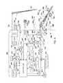
- FIG. 4Schematic diagram of the bi-polar driver system.
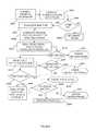
- FIG. 5AAblation Procedure without Auxiliary probe.
- FIG. 5BAblation Procedure with Auxiliary probe.
- FIG. 6Side view Hybrid bi-polar needle for nerve ablation.
- FIGS. 6A and 6Billustrate examples of directing energy and limiting ablation to smaller regions and thereby avoiding other structures.
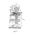
- FIG. 7Side view of auxiliary nerve probe.
- FIGS. 7A and 7Billustrate side views of auxiliary dual-tipped nerve probe.
- FIG. 8Side view of guided ablation procedure with auxiliary nerve probe(s).
- FIG. 9Sample electro-surgery waveforms.
- FIG. 10Side view of visually guided ablation procedure.
- FIGS. 11-11AController and probe data base structure.
- FIG. 12is a side view of a single axis electrosurgical probe having equal surface area electrodes.
- FIG. 13is a side view of a single axis electrosurgical probe having two electrodes of differing surface areas.
- FIG. 14is a side view of a single axis electrosurgical probe having two electrodes of differing surface areas.
- FIG. 15is a side view of a single axis electrosurgical probe having three electrodes.
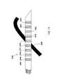
- FIG. 16is a side view of a single axis electrosurgical probe having three electrodes and a curved handle portion.
- FIG. 17is a side view of a single axis electrosurgical probe having multiple electrodes transverse a nerve.
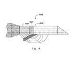
- FIG. 18is a side view of a single axis electrosurgical probe having multiple electrodes parallel to a nerve.
- FIG. 19is a side view of a single axis electrosurgical probe having multiple electrodes crossing a nerve at an angle.
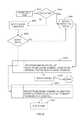
- FIG. 20is a flowchart illustrating certain aspects of a system management method consistent with the present invention.
- FIG. 21is a flowchart illustrating certain aspects of a system management method consistent with the present invention.
- FIG. 22is a flowchart illustrating certain aspects of a system management method consistent with the present invention.
- FIG. 23Ais a flowchart illustrating certain aspects of a system management method consistent with the present invention.
- FIG. 23Bis a flowchart illustrating certain aspects of a system management method consistent with the present invention.
- FIG. 23Cis a flowchart illustrating certain aspects of a system management method consistent with the present invention.
- FIG. 24is a flowchart illustrating certain aspects of a system management method consistent with the present invention.
- FIG. 25is a tabular representation of a therapeutic energy protocol consistent with the present invention.
- FIG. 26is a graphic representation of a therapeutic energy protocol consistent with the present invention.
- FIG. 27is a perspective view of an electrosurgical probe featuring a multi-position switch to control stimulation current.
- Corrugatorsupercili muscles—skeletal muscles of the forehead that produce brow depression and frowning.
- Cepressor anguli orisskeletal muscle of the corner of the mouth that produces depression of the corner of the mouth.
- Depressor labii inferiorisskeletal muscle of the lower lip that causes the lip to evert and depress downward.
- Dystoniasmedical condition describing an aberrant contraction of a skeletal muscle which is involuntary.
- Frontalisskeletal muscle of the forehead that produces brow elevation or raising of the eyebrows.
- Hyperhidrosiscondition of excessive sweat production.
- Masseterskeletal muscle of the jaw that produces jaw closure and clenching.
- Orbicularis oculioskeletal muscle of the eyelid area responsible for eyelid closure.
- Orbicularis oriskeletal muscle of the mouth area responsible for closure and competency of the lips and mouth.
- Parasymapatheticrefers to one division of the autonomic nervous system.
- Platysma myoidesskeletal muscle of the neck that protects deeper structures of the neck.
- Procerus musclesskeletal muscle of the central forehead responsible for frowning and producing horizontal creasing along the nasofrontal area.
- Procerusshortening
- Rhinorrheaexccessive nasal mucous secretions.
- Supercillia portion of the corrugator muscle that sits above the eyelids.
- Temporalisskeletal muscle of the jaw that stabilized the temporamandibular joint.
- Zygomaticus majorskeletal muscle of the face that produces smiling or creasing of the midface.
- ADCAnalog to digital converter.
- BAUDSerial communication data rate in bits per second.
- BYTEDigital data 8-bits in length.
- CHARACTERSymbol from the ASCII set.
- CHECKSUMNumerical sum of the data in a list.
- CPUCentral processing unit.
- EEPROMElectronically erasable programmable read only memory.
- FLASH MEMORYElectrically alterable read only memory. (See EEPROM)
- UIGraphical user interface.
- HEXADECIMALBase 16 representation of integer numbers.
- 12C BUSInter Integrated Circuit bus. Simple two-wire bi-directional serial bus developed by Philips for an independent communications path between embedded ICs on printed circuit boards and subsystems.
- the I2C busis used on and between system boards for internal system management and diagnostic functions.
- INTERRUPTSignal the computer to perform another task.
- PCPersonal computer
- PWMPulse-width modulation
- ROMRead only memory.
- FIG. 1illustrates two main components and one optional component, which are the energy generator 400 , the probe 371 (alternate probes are described in FIGS. 3A-D ) and optionally probes 771 or 772 that may be used.
- the novel probe 371would combine a unique bipolar configuration in a single MIS needle, is inserted into the patient using MIS techniques.
- the probewhich may contain and/or convey various functions described later, is initially guided anatomically to the region of the anticipated or desired location.
- Various means of locating the tip 301are utilized of placing the zone of ablation in the proper area to interrupt signal flows through the nerve 101 .
- the ‘novel’ probeperforms a variety of functions, such as stimulation, optical and electronic guidance, medication delivery, sample extraction, and controlled ablation.
- This bi-polar electrodeis designed as a small diameter needle inserted from a single point of entry thus minimizing scaring and simplifying precise electrode placement. This low cost, compact design provides a new tool to the art.
- Probesmay emit fiber optic illumination for deep applications using electronic guidance as taught in FIGS. 1 and 8 .
- the inventionoffers a simple low cost ablation probe that is capable of performing precise ablation while minimizing damage to nearby tissue structures.
- the metered ablation energy and precise probe targetinggive the practitioner a tool is also not available in prior art.
- the practitionerhas unprecedented control of treatment permanence in a minimally invasive procedure. Such a procedure is typically performed in less than one hour with only local anesthetic and would require no stitches or chemicals common to prior medical art.
- the userinitiates the treatment via switch(s) 410 and 310 using the selected power setting 404 ( FIG. 4 ).
- the controllerconfigures the generators 411 ( FIG. 4) and 412 to the amplitude frequency and modulation envelope, delivering 50 KHz-2.5 MHz of 5 to 500 watts of available energy.
- the summing junction 413combines the RF outputs as the application requires and passes them to the pulse-width modulator 415 for output power control.
- the output of modulation generator 420is applied to the multiplier 415 with radio frequency RF signals 422 and 423 . This permits complex energy profiles to be delivered to a time variant non-linear biologic load. All of these settings are based on the information provide to the generator by the installed probe 371 the selected power 404 settings, and the modulation envelope 420 ( FIG. 4 ) settings, which are then loaded by the generator 421 .
- both a high amplitude sine wave 910 ( FIG. 9 ), used for cutting, and a pulse-width modulated (or PWM) sine wave 920 , used for coagulation,are well known to electro-surgery art.
- Precise power rates and limits of average total powerare controlled via integrator 435 minimizing damage to nearby structures or burning close to the skin for shallow procedures.
- nearby structures 111 ( FIG. 2A )are too close to be avoided by electrodes such as 371 ( FIG. 3A) and 372 ( FIG. 3B )
- additional probe geometries as taught in FIGS. 3D , 6 , 6 A, and 6 Boffer novel methods to direct energy and limit ablation to a smaller region, thereby avoiding other structures.
- a hardwired switch 436disables the power amplifier in the event of a system fault, the probe is unplugged or over power condition, thus protecting both the patient and practitioner.
- the output of the modulator 415is applied to the input of the power amplifier 416 section.
- the power amplifier's 416 outputsare then feed into the impedance matching network 418 , which provides dynamic controlled output to the biologic loads that are highly variable and non-linear, and require dynamic control of both power levels and impedance matching.
- the tuning of the matching network 418is performed for optimal power transfer for the probe, power level, and treatment frequencies settled.
- the system's peak poweris 500 watts for this disclosed embodiment. Precise control is established by the proximity of the tip and the control loops included in the generator itself.
- the final energy envelope 420is delivered to probe tip 301 and return electrodes 302 .
- a low energy nerve stimulator 771has been integrated into the system to assist in more precise identification of nearby structures and for highly accurate target location.
- additional sensorssuch as temperature 330 , voltage, frequency, current and the like are read directly from the device and/or across the communications media 403 to the probe.
- FIG. 3DIn addition to the substantial radially-symmetric ablation patterns with probes as taught in 371 ( FIG. 3A) and 372 , switching or dividing ablation power to multiple electrodes ( FIG. 3D ) can generate an asymmetric ablation zone.
- This high intensity source 608 with probe 610FIGS. 6 and 6A ) minimizes damage to nearby structures 111 or the burning of skin 330 in shallow procedures.
- FIGS. 2A and 3Didentify probe configurations for selective or asymmetric ablation.
- the power amplifier output 430 and buffered the feedback signals 437are connected to an Analog to Digital converter (or ADC) 431 for processor analysis and control. Said signals 437 control power modulation 420 settings and impact the impedance matching control signals 419 .
- This integrated power signal 437is recorded to the operating-condition database ( FIG. 11 ) for later procedure review. This power level is also compared to reading taken from the probe 1492 ( FIG. 11A ) as compared against procedure maximums, which if exceeded will in turn disable the amplifier output, thereby protecting the patient from error or equipment fault. Similarly, limits from the probe and generator sensors such as temperature 330 are also used to terminate or substantially reduce the modulated power levels and ultimately the procedure.
- serial communications 403(or bus).
- Serial communicationsis used because it is commonly available to most single-chip microprocessors. This or similar methods (e.g. I2C, or SPI) may be used, but this disclosed embodiment will use serial for its simplicity.
- Serial communications 403permits the generator to address and control EEROM memory 331 , temperature sensors 330 , processors, ADC and DACs within the single-chip microprocessor embedded in the probe itself.
- the userselects the desired power setting 404 and based on probe identification read from the EEROM or microprocessor 331 makes the appropriate configurations.
- the probe 371is connected via cable 1334 ( FIG.
- the controller 401( FIG. 4 ) reads the stored time register from ID memory module 331 . If the probe's initialized time 1467 ( FIG. 11 ) is zero, the current real-time clock 482 value is written to probe's 331 's initial time register via serial bus 403 . If time read on module 331 is non-zero, the probe's initial time register is added to two (2) times the procedural time (based on the probe type) FIG. 14 1420 . If that value when compared to current real-time clock 482 , is less than current time, the controller will alert the practitioner via display 450 , speaker 451 and, flashing probe illumination 608 , that the procedure will be terminated and the probe rendered invalid.
- the controller 401also verifies selected procedure 1415 ( FIG. 11 ) for compatibility with installed probe. If incompatible, the user is also prompted to select a different power setting 404 , procedure, or probe 371 . If probe 371 matches power setting 404 , the system enables power amplifier 416 , guide light source 408 , and low-voltage nerve simulation 732 . Both of these procedures are enforced by a mandatory “hand shake” protocol and the serialized information, which must be present and properly verified by the electronic circuitry for a procedure to be instituted. During a clinical procedure, information is required to be conveyed by the embedded electronics contained within the probe, which provides another way of enforcing this protection and thus again preventing unauthorized re-use.
- the ultimate goalis prevent cross-contamination between patients.
- the probewill accomplish this by being unique, serialized, and given the above procedures. Once plugged in, the probe will enter the serial number into the data logging system via the serial bus 403 and circuit logic will thereafter prevent re-use of the probe and cross-contamination that would occur. Further, this scheme will prevent the use of unauthorized third party probes, for they will not be activated, preventing potential inferior or uncertified probes from being used and presenting potential danger to the patient.
- auxiliary probe 771Prior to treatment, the practitioner may use auxiliary probe 771 ( FIG. 4 ), to locate target 101 and nearby structures 111 as taught in FIGS. 4 , 7 , 7 A, 8 , and 10 .
- needle 771When needle 771 is in place, the practitioner may locate and place a mark or marks on the surface of the skin 755 (see FIGS. 7 and 8 ) or leaves auxiliary probe 771 in place.
- probe tip illumination 448 from source 408is visible to practitioner aiding in probe placement to pre-marked location.
- FIG. 6AIn other procedures, whereby somewhat larger targets are sought, such as more diffuse nerve structures or small areas of abnormal growth (e.g. such as cancer) the injection of specially designed dyes that attach to target structures are used, as taught in FIG. 6A .
- the probe 610FIG. 6
- the light source 608illuminates quantum-dot/dye tagged antibody 670 .
- the dyefluoresces 675 at a frequency/wavelength of a particular material and will typically emit light in the visible to infrared (or IR) or potentially other wavelength regions.
- the return fiber(s) 680deliver emissions 675 to the detector 478 for measurement and are the result is then displayed on bar graph 554 ( FIG.
- Low energy nerve stimulation current 810( FIG. 8 ) assist in locating desired treatment region and avoiding nearby structures.
- Probe 771is selectable between nerve stimulator and current measurement to/from auxiliary probe tip 702 ( FIG. 8 ).
- Return electrode 736provides a return path for local ground 735 .
- Ablation probe switch 367selects low-energy stimulator/receiver and high-energy ablation to/from probe 372 .
- Amplitude of measured guidance current 811 and light 478are transmitted to display 554 , and audio feedback 452 through the speaker 451 .
- Disclosed inventionprovides optical sources 408 that aid in probe placement ( FIG. 10 ) by supplementing stimulation source 732 and acting as preliminary guide.
- Probe 771is selectable between nerve stimulator or current 811 measurement and to or from the auxiliary probe tip 702 .
- the ablation probe switch 367selects low-energy stimulator/receiver or high-energy ablation to or from probe 371 , 372 , 373 , and 374 .
- the physician operatorwill have previously placed marks 755 on the surface of the skin by various means described.
- the physician operator 775will then see the tip when the 448 if the optical illumination is turned on. It 448 will provide a bright spot under the skin indicating the location of the tip in relation to the marks 755 .
- the physician 775will then guide the probe tip 301 into precise alignment under these marks 755 so as to enable ablation of that target tissue 101 .
- Real-time engineering parametersare measured such as average power 437 , luminous intensity 478 , probe current 811 , energy 438 and, temperature 330 to be recoded into USB memory 438 .
- the internal parameters disclosedsuch as frequency 423 , modulation 420 and such are recoded into USB memory 438 as well.
- probe, patient, and procedure parameters( FIG. 11 ) are written to local storage 438 .
- the practitionerdictates text and voice notes via microphone 455 , which are saved to memory 438 ( FIG. 1 ). All data and records are time stamped using the real-time clock 482 . This permits detailed post procedure graphing and analysis.
- the systemtransfers the data 438 recorded to the USB removable memory 1338 and to a file server(s) 1309 and 1307 .
- data transferis performed over Ethernet connection 480 .
- Probe usage records 1460FIG. 11
- Parallel recordsare mirrored to local storage 1309 and remote server 1306 storage 1307 via Ethernet connection 480 or similar means.
- Sensitive recordsare encrypted and transferred via secure network connection and also written to removable module 1320 .
- the database contained on the remote servertracks the following information: equipment by manufacture, probe accessory inventory, usage, billing, repair/warranty exchange information, and program recorders.
- the relational databasesare automatically updated to reflect new billing/procedure codes 1416 , potential power settings 1417 and the like. This insures that the equipment is current and alerts the practitioner to new probes/procedures as they are developed and certified.
- FIG. 1Bi-Polar Driver System
- FIG. 1identifies the two required components of the system, various modules and optional items.
- the two components always utilized during a procedurewill be the energy generator/controller/data storage device 400 and probe 371 .
- 400contains advanced electronic systems capable of recognizing a properly authorized probe, preventing re use of a previously used probe, generating appropriate energy as described, performing safety checks, storing data, and other functions as described.
- Main functions of 400may include, but not be limited to, generation of light, generation of location-stimulation currents, generation of ablation energies, data logging, storage, communication and retrieval, and other functions critical to a MIS procedure.
- Probe 371 and its various formsare single puncture bipolar surgical tools that may be used in identifying proper location of its tip 301 , in relation to target tissue 101 which is desired to be ablated, modified or destroyed. Probe 771 and its various derivatives may optionally be used to assist in locating and properly positioning tip 301 of probe 371 .
- FIG. 2Isometric View of the Bi-Polar Probe
- Bi-polar probe 310represents probes 371 , 372 , 373 shown in FIGS. 3A-C with exception to type of needlepoint on the probe.
- FIG. 3Dvaries from the other because it has a split return probe.
- Bi-polar probe 310(not drawn to scale) consists of insulating dielectric body 309 made from a suitable biology inert material, such as Teflon, PTFE or other insulative material, covering electrode 302 except for where 302 is exposed as a return electrode.
- Conductive return electrode 302 tubeis fabricated from medical grade stainless steel, titanium or other conductive material.
- Hollow or solid conductive tip electrode 301protrudes from surrounding dielectric insulator 305 . Sizes of 309 , 302 , 305 , and 301 and its inner lumen (diameter, length, thickness, etc.) may be adjusted so as to allow for different surface areas resulting in specific current densities as required for specific therapeutic applications.
- Hollow Electrode 301often used as a syringe to deliver medication such as local anesthetic.
- Tip electrode 301is connected to power amplifier 416 via impedance matching network 418 ( FIG. 4 ).
- Return electrode(s) 302delivers return current to power amplifier 416 via impedance matching network 418 .
- Dielectric insulator in the disclosed embodimentis a transparent medical grade polycarbonate acting as a light pipe or fiber optic cable.
- Light source LED or laser 408FIG. 4
- dielectric insulatoris replaced with a plurality of optical fibers for viewing and illumination as taught in FIG. 6 .
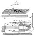
- Ablation regions 306 and 140extend radially about electrode 301 generally following electric field lines. For procedures very close to skin 330 a chance of burning exists in region 306 . To minimize the chance of burning, a split return electrode probe 374 in FIG. 3D is offered. Thereby concentrating the current away from region 306 to 140 or vice versa.
- insulator 307splits the return electrode into two sections 302 and 303 , dividing return current ratio from 0-50%, which may also be selectively activated. Active electrodes are also split into two sections 301 and 311 so energy may be directed in a desired direction. This electrode configuration is identified on the proximal portion of the probe so the operator may position the needle and electrodes accordingly.
- FIG. 6teaches a laser directed ablation for more precise energy delivery.
- FIG. 2AIsometric View of Split Bi-Polar Probe.
- the bi-polar probe 380(not drawn to scale) consists of an insulating dielectric body 309 made from a suitable biologically inert material, such as Teflon PTFE or other electrical insulation, that covers split return electrodes 302 and 303 .
- the disclosed conductive return electrodes 302 and 303are fabricated from medical grade stainless steel, titanium or other electrically conductive material.
- Hollow or solid split conductive tip electrodes 301 and 311protrude from the surrounding dielectric insulator 305 .
- the operation of the hollow/split conductive tipis very similar to probe tip 310 as taught in FIG. 3D .
- Ablation regions 1203 (FIG. 10 ) and 140 - 144extend radially about electrode 301 generally following electric field lines.
- the disclosed split electrode 380permits dividing or splitting energy delivered to electrode pairs 301 / 302 and 311 / 303 .
- the disclosed division or ratio between pairsis 0-100%.
- Dual amplifiers or time multiplexing/switching main amplifier, 416 located between electrode pairs,directs energy to target 101 avoiding 111 . This simple switch network reliably ratios electrical energy while minimizing damage to nearby structures.
- FIG. 3AConical Bi-Polar Needle
- Bi-polar probe 371discloses conical shaped electrode 301 and tip 351 for minimally invasive single point entry.
- Probe diameter 358is similar to a 20-gage or other small gauge syringe needle, but may be larger or smaller depending on the application, surface area required and depth of penetration necessary.
- electrode shaft 302is 30 mm long with approximately 5 mm not insulated. Lengths and surface areas of both may be modified to meet various applications such as in cosmetic surgery or in elimination of back pain.
- the conductive return electrode 302is fabricated from medical grade stainless steel, titanium or other conductive material.
- the dielectric insulator 305 in the disclosed embodimentis a transparent medical grade material such as polycarbonate, which may double as a light pipe or fiber optic cable.
- the high intensity light source 408 LED/laser( FIG. 4 ) provides guidance Illumination 448 at working end of probe.
- the illumination source modulation/flash rateis proportional to the received stimulation current 810 as taught in FIG. 8 .
- a small diameter electrodepermits a minimally invasive procedure that is typically performed with local anesthetic. This configuration may contain lumens for delivery of agents as described elsewhere.
- FIG. 3BHollow Chisel
- the hollow chisel electrode 352is often used as a syringe to deliver medication such as local anesthetic, medications,/tracer dye.
- the hollow electrodemay also extract a sample.
- Dielectric insulator 305 in the disclosed embodimentis a transparent medical grade polycarbonate and performs as a light pipe or fiber optic cable. The novel dual-purpose dielectric reduces probe diameter and manufacturing costs.
- Light source 408typically a LED or laser ( FIG. 4 not shown), provides Illumination 448 at the working end of probe. It provides an illumination source for guiding the probe under the skin.
- a second embodiment, as taught in FIG. 6dielectric insulator is replaced/combined with plurality of optical fibers for viewing/illumination.
- FIG. 3CTapered Conical
- the bi-polar probe 373discloses a tapered conical shaped probe for minimally invasive single point entry. It is constructed similarly to probe 371 as taught in FIG. 3A . Probe tip is not drawn to scale to teach the tip geometry. In disclosed embodiment, electrode 301 is approximately 5 mm long and fabricated from medical grade stainless steel but may be of various lengths to accommodate specific application and surface area requirements.
- the solid tapered conductive tip electrode 353protrudes from tapered dielectric insulator 305 .
- Transparent dielectric insulator 305also performs as light pipe or fiber optic cable terminated to high intensity light source 408 ( FIG. 4 ) providing illumination 448 .
- the electrode assemblyis mounted in an ergonomic handle 388 (which has not been drawn to scale). Handle 388 holds ablation on/off switch 310 , ablation/stimulation mode switch 367 , identification module 331 and terminations for cable 1334 ( FIG. 13 ).
- Temperature sensor 330located close to tip monitors tissue temperature.
- FIG. 3DSplit Conical Bi-Polar Probe
- Bi-polar probe 374(not drawn to scale) consists of insulating dielectric body 309 made from a suitable biologically inert material, such as Teflon, that covers split return electrodes 302 and 303 .
- Conductive return electrodes 302are fabricated from medical grade stainless steel, titanium or other suitable conductive material.
- Hollow or solid split conductive tip electrodes 301 and 311protrude from surrounding dielectric insulator 305 . Their operation is very similar to probe tip 380 as taught in FIG. 2A .
- Solid tapered conductive tip electrodes 311 and 301protrude from transparent dielectric insulator 305 .
- Dielectric insulator 305also performs as a light pipe or fiber optic cable terminated to high intensity light source 408 providing illumination 448 .
- Probe handle(not drawn to scale) encloses memory module 331 , on/off switch 310 and mode switch 367 .
- Temperature sensor 330(located close to tip) monitors tissue temperature.
- Split electrode 380( FIG. 2A ) permits dividing or splitting energy delivered to electrode pairs 301 / 302 and 311 / 303 .
- Dual amplifiers or time multiplexing/switching main amplifier 416are located between electrode pairs directing energy to target 101 avoiding 111 creating asymmetric ablation volume. A small diameter electrode needle is injected from a single point of entry minimizing scaring and simplifying precise electrode placement.
- Connectionsconsist of a tapered dielectric sleeve 309 covering the ridged stainless electrode tube 302 .
- Insulating sleeve 309is made from a suitable biologically inert material, which covers electrode 302 .
- Dielectric 305insulates conical tipped electrodes 351 and 301 .
- FIG. 5AAblation Procedure (Without Auxiliary Probes)
- Ablation probe 371is inserted and directed anatomically into the area where the target nerve to be ablated (Box 531 ) is located.
- Test current 811is applied (Box 532 ). If probe is located in the immediate proximity of the target nerve a physiological reaction will be detected/observed (Example: During elimination of glabellar furrowing, muscle stimulation of the forehead will be observed). If reaction is observed, then a mark may optionally be applied on the surface of the skin to locate the area of the nerve. Power is applied (Box 535 ) in an attempt to ablate the nerve. If physiological reaction is not observed, (Box 534 ) the probe will be relocated closer to the target nerve and the stimulation test will be repeated (Box 536 & 537 ). If no physiological reaction is observed, the procedure may be terminated (Box 544 ). Also, the probe may be moved in any direction, up, down, near, far, circular, in a pattern, etc. to create a larger area of ablation for a more permanent result.
- the ablation powermay be set higher (Box 538 ), alternatively, as mentioned, the needle may be moved in various directions, or a larger dosage of energy may be reapplied, to form a larger area of ablation for more effective or permanent termination of signal conduction through the nerve.
- stimulation energymay be applied again (Box 541 ). If there is no stimulation, the procedure is completed (Box 544 ). If there is still signal flow through the nerve (stimulation or physiological reaction) then the probe may be relocated (Box 542 ) and the procedure is started over again (Box 533 ).
- FIG. 5BFlow Chart of Visually Guided Ablation Procedure Using Auxiliary Probes Such as 771 and 772
- Auxiliary probes 771 and 772provide a method to quickly and accurately locate target structure 101 and subsequently mark target location 755 .
- Auxiliary probesmay be much smaller (like acupuncture needles) than ablation probes. Structures are marked typically with an ink or similar pen allowing the illuminated ablation probe 371 or other ablation probe to be quickly guided to mark 755 .
- non-illuminated probesmay be used allowing the practitioner to simply feel for the probe tip.
- probe 771( FIG. 8 ) us employed as an electronic beacon. Small current 811 , which is similar to the stimulation current but smaller, from probe tip 702 is used to guide ablation probe 372 ( FIG. 8 ).
- Operation 530inserts auxiliary probe 771 or 772 ( FIGS. 7 and 7A ) thru skin 330 and muscle layer(s) 710 near nerve 101 .
- Target 101 depth 766is measured ( FIGS. 7 and 7A ) using auxiliary probe markings 765 .
- Decision 533checks if the probe is in position if not adjustments are performed in 534 .
- Operation 532enables nerve simulation current 811 . When muscle stimulation is obtained or physiological reaction is obtained, Auxiliary probe tip is in place. Depth may be noted by reading marks 765 and location marks 755 may be made in operation 535 . With the probe in position under mark in operations 536 and 537 , operation 538 sets power level 404 and closes ablation switch 410 .
- stimulationmay be applied directly from the ablation probe as taught elsewhere.
- Operation 540 and controller 401set generator 411 ( FIG. 4 ) frequencies, modulation 420 envelope and enables power amplifier 416 to deliver preset ablation energy.
- Region 1203FIG. 10 shows the general shape of the ablation region for conical tip 301 for example.
- procedure 540(nerve conduction) is tested in 541 .
- Probe amplifier 416delivers small nerve stimulation current 811 from electrode 301 or Auxiliary probe 771 or both. Based on the nerve conduction test 541 if the desired level of conduction is achieved the procedure is compete. Operation 542 moves the probe to the next position and repeats conduction test 541 . If compete, the probe(s) is removed in operation 544 . Number and ablation intensity/energy are set by the particular procedure and the desired permanence.
- the practitionerselects the procedure/power level 404 ( FIG. 4 ) and controller 401 compares the installed probe via identification 331 ( FIG. 4 ) for compatibility with selected procedure. The practitioner is alerted if the installed probe is incompatible with selected power range 404 .
- ablation regions 140 , 141 , 142 , 143 , and 144are shown in FIG. 10 .
- Ablationstarts with area 144 , then the probe is moved to 143 and so on to 140 .
- movementmay be during insertion, moved laterally, in a circular manner or other manner to enlarge the area of targeted nerve destruction.
- Nerve responsesmay be tested after each ablation allowing the practitioner to immediately check the level of nerve conduction. Probe position and power adjustments are made before applying additional ablations if required.
- Accurate probe location tools and methods taught hereinpermit use of minimal ablation energy thereby minimizing damage to non-target structures. This translates to reduced healing time and minimal patient discomfort.
- the instant inventiongives the practitioner a new tool to perform a minimally invasive nerve conduction limiting procedure with the ability to select, temporary or permanent nerve conduction interruption with a new level of confidence.
- This new tooloffers a low cost procedure performed typically in office or outpatient setting often taking less than one hour with local anesthetic. In contrast to prior art where surgical procedures require stitches and longer healing intervals with limited control of permanence (nerve re-growth).
- FIG. 6Side View of the Bi-Polar Probe 610 With Enhanced Laser Targeting
- Probe insertion and placementis same as taught in FIG. 3 .
- Probe constructionis the same as FIG. 3 with the dielectric 305 having embedded optical fibers 690 and 680 providing imaging/illumination. Additional fiber(s) 690 - 691 are illuminated by a high intensity laser source.
- target nerve 101 or ablation region 640is in close proximity to second nerve 111 or skin 330 bi-polar probes 371 or 372 ( FIG. 3 ) create an annular ablation region between electrodes 301 and/or 302 , potentially damaging nearby structures such as other nerves 111 .
- laser 608FIG. 4
- target 670FIG. 6A
- fiber(s) 690Fiber(s) transmitting high intensity laser light to ionized region 640 is illuminated by fiber(s) 690 .
- RF energy 470is delivered to electrodes 301 and 302 .
- Probe 610improves on the already very precise ablation taught in FIG. 3 with the addition of a low power laser (or other type light source) and fiber delivery system.
- a diode pumped Nd:YAG (Neodymium Doped Yttrium Aluminum Garnet) laseris offered as an example and not a limitation.
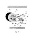
- FIG. 6ASide View is the Florescence Emission Guided Hybrid Bi-Polar Tumor Probe
- Probe constructionis similar to FIGS. 3A and 6 with dielectric 305 embedded with a plurality of optical fibers 380 , 690 , and 680 for illumination detection/imaging. These enhanced systems and processed augments the selective nature of previously disclosed probes.
- Fiber(s) 690 - 691are illuminated by a high intensity light source(s) 608 which is typically a tunable laser or UV LED.
- Source(s) 608FIG. 4
- Source(s) 608FIG. 4
- Excitation/illumination wavelength(s)are specific to the dye/nano-particle used with marker 670 that is very specific for the desired target 671 .
- the marker/tagis typically a protein specific antigen combined with a florescent marker.
- the novel probe illuminationpermits delivery of intense illumination to the target for maximum system sensitivity. Many dyes excited by short (Blue/UV) wavelength light are transmitted poorly in tissue but are easily delivered by fiber 690 .
- a second application offered for hybrid bi-polar ablation probe 610is for locating/destroying small cancer lesions. The probe addresses cases where surgery is not practical or it dangerous due to location or sub-operable size.
- Quantum-dot or dye tagged antibody materials 670are injected into the patients where it attaches to target structure 671 . Once tagged, cancer node(s) may be located, tested, and treated.
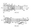
- FIG. 7Side View of Auxiliary Single Tipped Nerve Probe
- This probemay be used in conjunction with any of the therapeutic probes 371 and their derivatives.
- the needleitself will be very fine in nature, such as an acupuncture type needle. By its small size, numerous needle insertions may be accomplished with no scarring and minimal pain.
- the probe 771will be inserted in the vicinity of the target tissue through skin 330 .
- the exposed tip of 771 , 702will be exposed and electrically connected to generator 732 via wire 734 .
- the surface of probe 771is covered with dielectric 704 so the only exposed electrical contact is surface 702 and return electrode 736 .
- Exposed tip 702will be advanced to the vicinity of target 101 and test stimulation current will be applied. Appropriate physiological reaction will be observed and when the tip 702 is properly located, depth will be noted via observing marks 765 .
- External mark 755may be applied for reference.
- Ablation probe 371may then be advanced to the proximity of the target tissue under the X mark 755 and ablation/nerve destruction as described elsewhere may be performed.
- FIG. 7ASide View of Auxiliary Dual-Tipped Nerve Probe
- Dual tipped probe 772offers an additional embodiment that eliminates return electrode pad 736 .
- Probe frame/handle 739holds two fine needles, 702 and 701 , in the disclosed embodiment that are spaced a short distance (a few mm)-mm apart ( 730 ).
- the shaft of conductive needle 701is covered with dielectric insulator 706 , similar to the construction of probe 771 ( FIG. 7 ).
- the shaft of the second conductive needle 702is covered with dielectric insulator sleeve 703 .
- Electric generator 732provides current to the probes via conductors 734 and 735 . Current originates from 701 and returns via electrode 702 . Large probe handle 739 is drawn out to teach the dual probes.
- markers 765are printed on needle shafts.
- Dielectric insulating sleeves 703 and 706isolate the needle shaft current from muscle layer 710 .
- Current applied via generator 732stimulates the nerve directly while avoiding muscle 710 .
- Smaller probe tips with smaller currentpermits accurately locating small structures.
- Probes 702 and 701are very small gage needles similar in size to common acupuncture needles, thus permitting repeated probing with minimal discomfort, bleeding, and insertion force. Sharp probes are inserted thru skin 330 and muscle layer(s) 710 near nerve 101 . The practitioner locates target nerve 101 , then the skin surface may be marked 755 as location aide for ablation step as shown in flow chart ( FIG. 5B ). Once the desired site of ablation is located, ablation probe(s) 610 ( FIG. 6 ), 371 and related probes ( FIG. 3 ), may be inserted under skin 330 , illuminated 448 by tip 305 . They are visible through skin (via illumination 448 from tip 305 ) and are guided to mark 755 ( FIG. 8 ). The observed intensity 765 from illumination source 305 is used as an estimator of measured depth 765 . This simple probe system permits rapid, accurate locating of target structures with minimal pain and injury. Accurate target location permits use of lower ablation energy thereby minimizing damage to nearby structures.
- FIG. 8Side View of Guided Ablation Procedure with Auxiliary Nerve Probe(s)
- Auxiliary probes 771 and 772are used to accurately locate target structure 101 .
- Probe 771holds a fine conductive needle 702 that has a shaft covered with dielectric insulator 704 .
- Electric generator 732provides a small current to the auxiliary probe via conductor 734 and return conductor 735 via return electrode 736 .
- the sharp auxiliary probeis inserted thru skin 330 and muscle layer(s) 710 near target nerve 101 .
- Dielectric insulating sleeve 704isolates needle shaft from muscle layer 710 . Current is applied via generator 732 thereby stimulating the nerve directly while avoiding muscles 710 .
- Prior art probes without insulating sleeve 704stimulate both the nerve and muscle simultaneously, masking nerve 101 and subsequently making nerve location difficult.
- probe 701is used as a receiver detecting current 811 from electrode 301
- Moving probe tip 301 horizontally 1202 and in depth 766 relative to auxiliary probe 702changes current 810 inversely proportional to distance.
- Detected signal current 811 isolated and buffered by amplifier 430is measured and the current is displayed to simple bar graph 554 for rapid reading.
- audio feedbackin which the tone is modulated by proximity of probe tip 351 , 352 or equivalent in relation to auxiliary probe tip 702 is provided to minimize or eliminate the practitioner having to look away from the needle, thus assisting in accurate probe placement.
- Variable frequency/pitch and volume audio signalare proportional to sensed current 811 that is generated by 452 .
- the tone signal emitted by speaker 451FIGS.
- illumination source 408is modulated by amplifier 456 to blink at a rate proportional to the sensed current.
- Thispermits the practitioner to quickly and accuracy guide ablation probe 372 into position using a combination of audio and visual guides.
- the audio and visual aidesalso reduce the practitioner's training/learning time.
- the novel real-time probe placement feedbackgives the practitioner confidence that the system is working correctly so he/she can concentrate on the delicate procedure. Accurate probe location permits use of minimal energy during ablation, minimizing damage to non-target structures and reducing healing time and patient discomfort.
- Lower energy pulse width modulated (or PWM) sinusoid 920 for coagulationis also well known to electro-surgery art. Variations of cut followed by coagulation are also well known.
- FIG. 10Side View of Visually Guided Ablation Procedure
- Auxiliary probes 771 and 772( FIGS. 7 and 7A ) have accurately located target structure 101 and subsequently marked target locations 140 to 144 .
- Shallow structuresare marked typically with ink pen ( 755 ) allowing illuminated ablation probe 371 , 372 or equivalent to be quickly guided to that point.
- probe 771is employed as electronic beacon, small current 811 from probe tip 702 is used to guide ablation probe 372 as taught in FIG. 8 .
- Region 1203shows the general shape of the ablation region for conical tip 301 .
- Tip 301is positioned in close proximity to target nerve 101 .
- Ablationgenerally requires one or a series of localized ablations. Number and ablation intensity/energy are set by the particular procedure and the desired permanence.
- FIGS. 11-11AController and Probe Data Base Structure
- Controller 101maintains local probe 1460 , patient 1430 , and procedure 1410 databases. All work together to insure correct probes and settings are used for the desired procedure. Automatically verifying that the attached probe matches selected procedure and verifying probe authentication and usage to avoid patient cross contamination or use of unauthorized probes. Automatic probe inventory control quickly and accurately transfers procedure results to the billing system.
- FIG. 11Provide Parameters Code(s) Database 1410
- the practitionerselects the desired procedure from list 1410 .
- “TEMPORARY NERVE CONDUCTION” 1411 , “SMALL TUMOR 1CC” 1412 , and “SMALL NERVE ABLATE” 1413are a few of the choices.
- Each procedurehas a unique procedure code 1416 to be used in the billing system.
- Power range parameter 1417is a recommended power setting via power level control 404 .
- the recommended probe(s) Associated with procedure 1415 and power range parameter 1417are listed in parameters 1419 . With the probe connected, the part number is read from memory 331 ( FIGS. 1 , 3 and 4 ) and compared to list 1419 .
- the total power parameter 1418is the maximum energy that the system may deliver for this procedure and is determined by the procedure code, probe being used and software parameters. These parameters may be modified, updated and changed as required by addition of new probes and procedures allowed/approved. Power is delivered, measured and totaled with integrator 435 ( FIG. 4 ).
- the power integration circuitis designed as a hardwired redundant safety circuit that turns off the power amplifier if maximum energy is exceeded. This novel feature protects patients from system fault or practitioner error. Standard procedure time 1420 is doubled and added to current RTC 482 then written to probe memory 331 (in FIG. 1 ).
- FIGS. 11 & 11 AProvide Usage Authorization Database 1460
- Probe 371 and equivalents ( FIGS. 3A-D ) typeis selected from recommended list 1419 and is connected via cable 1334 ( FIG. 1 ) to control unit 101 .
- controller 401FIG. 4
- controller 401FIG. 4
- start time 1487 readis zero (factory default)
- current real time clock 482FIG. 4
- twice the standard procedure time 1420 parameteris added to RTC 482 and written to time register 1487 via serial bus 403 .
- various parameterssuch as peak temperature 1473 , power 1472 , impedance, etc. . . . are read, scaled, stored and displayed. Parameters such as procedure start 1467 ; end time 1468 , serial number 1469 , and part number 1468 are recorded as well. Critical parameters are written to local high-speed memory 438 for display and analysis. On a time permitting or end of procedure, data is mirrored to removable USB 1320 memory stick 1338 . Probe specific parameters 1463 are copied and written to probe memory 1338 for use at probe refurbishment facility. Database checksum/CRC(s) 1449 , 1479 , and 1499 are check and updated as required. Faults such as shorts (dielectric 305 ( FIG.
- the practitionerselects or enters patient name from previous procedure 1430 and creates a new record 1433 .
- a procedureis selected from 1410 (for example “TEMPORARY NERVE CONDUCTION” 1411 , “SMALL TUMOR 1CC” 1412 , and “SMALL NERVE ABLATE” 1413 ).
- Each procedurehas a unique procedure code 1416 that is used for the billing system.
- Other informationsuch as practitioners name 1440 , date 1435 is entered to record 1433 . As taught above probe appropriate for the procedure is connected and verified, part 1470 and serial number 1469 recorded.
- the practitionerenters additional text notes to file 1442 or records them with microphone 455 ( FIG. 5 ) to wave file 1445 for later playback or transcription.
- the instant inventionpermits temporary/permanent nerve conduction interruption. Thus, procedures are performed at intervals from months to years apart. A hands free integrated voice recorder is extremely useful. Detailed text and voice notes made while probing/ablating are also recording specific settings, and patient response. A feature that is very helpful when reviewing treatment progress and saves valuable time instead of writing notes. Practitioners play back voice/wave files 1445 with standard audio tools a his/or hers desk. Audio files 1445 can be sent via email or file transfer for transcription, updating note field 1442 .
- USB 1320 memory stick 1338( FIG. 1 ). If computer network 1326 such as Ethernet 802.11 or wireless 802.11x is available, files are mirrored to local storage 1309 , remote server 1307 . Patient name 1436 , procedure date 1435 , and procedure codes 1416 are automatically transferred via network or USB device 1320 to billing system 1306 .
- USB memory stickpermits continued operation in the event of a network 1326 failure. Data is loaded to USB memory 1338 for simple transfer to office computer 1306 ( FIG. 1 ) for backup. USB memory sticks 1320 have large data capacities in the tens to hundreds of megabytes at a low cost with long retention times. USB memory stick also support data encryption for secure transfer of patient data. Insuring patient is accurately billed with minimal office paper work. Probe inventory is automatic maintained with replacement probes automatic shipped as needed.
- one of the conductive electrodes 2002 , 2004may be selectively connected to a stimulation current source or an ablation current source as described above.
- the other electrode 2002 , 2004may be unconnected or connected as a ground or return path for the connected current source.
- conductive electrode 2002is configured to be connected to the ablation source making electrode 2002 the active electrode.
- electrode 2004is in this embodiment a return electrode.
- Either electrode 2002 , 2004may be connected to a current source or return with appropriate switches.
- the probe 2000 of FIG. 12also features a blunt tip 2010 rather than the conical tip 351 , chiseled tip 352 or other tips of FIG. 3 .
- the blunt tip 2010 of FIG. 12has a smooth rounded profile and is advantageous in certain instances to allow the probe to be easily advanced and maneuvered under the skin minimizing the risk of puncture or the cutting of adjacent tissue or anatomical structures.
- a blunt tip 2010may significantly reduce the bruising or other trauma associated with a procedure.
- the probe 2000 of FIG. 12may include a sensor 2012 .
- the sensormay be a temperature sensor 2012 .
- a temperature sensorprovides for active temperature monitoring within the ablation zone.
- a single axis electrosurgical probe of any configurationmay be implemented with a Kalman filter as taught by Conolly U.S. Pat. No. 6,384,384 which patent is incorporated herein by reference in its entirety.
- Kalman filtersare also used to estimate tissue temperature within an ablation volume. Kalman filters are suitable for use where well-defined tissue state changes occur at specific temperatures due to protein denaturation such as the denaturation of collagen at 65C. Kalman filter temperature monitoring is advantageous because the bulk and cost of a separate temperature sensor can be avoided.
- FIG. 13is a schematic view of an asymmetrical single axis probe 2014 also defining a longitudinal probe axis 2015 .
- the probe 2014features a first conductive electrode 2016 and a second conductive electrode 2018 having different surface areas.
- the first electrode 2016is an active electrode and the second electrode 2018 having a larger surface area is a return electrode.
- a probe having any surface area ratio between an active and return electrodemay be fabricated and used to achieve specific ablation results.
- the relative positions of the active electrode 2016 and the return electrode 2018 with respect to the tip of a given probemay be switched.
- the ratio of the active electrode 2016 to the surface area of the return electrode 2018is 1:3. Other ratios including 1:8 may be implemented to achieve specific results.
- the surface area ratiomay further be adjustable using a sleeve or other mechanism which will shield or cover a portion of on or both electrodes thus increasing or decreasing the length of the gap defining dielectric insulator 2019 .
- asymmetrical electrode surface areaswill result in asymmetrical heating and ablation because of the higher current density of the RF ablation energy at the electrode with smaller surface area.
- a tissue volume proximal the active electrode 2016may be asymmetrically heated due to the greater current density resulting from the relatively small surface area of the active electrode 2016 .
- Asymmetrical tissue heating coupled with precise RF power integration taught herein and various probe geometriespermits the formation of selected repeatable and controlled ablation volumes.
- FIG. 14schematically illustrates an alternative asymmetrical probe 2020 , which is similar in many respects to the asymmetrical probe 2014 of FIG. 13 .
- the asymmetrical probe 2020 of FIG. 14features an active electrode 2022 having a surface area greater than that of the return electrode 2024 .
- current densityis higher at the relatively smaller surface area electrode 2024 , thus ablation energy is concentrated in the dielectric insulator gap 2025 between the electrodes 2022 and 2024 nearer return electrode 2024 and away from the tip of the probe.
- FIG. 15is a schematic view of one embodiment of a multiple electrode probe 2026 .
- the multiple electrode probe 2026includes a substantially needle-shaped probe body 2028 which defines a longitudinal probe axis 2029 . More than two electrodes are associated with the probe body and positioned at various locations along the probe axis.
- the electrodesinclude an active electrode 2030 , a return electrode 2032 , and a stimulation electrode 2034 .
- the active electrodeis positioned near the tip of the multiple electrode probe 2026
- the return electrode 2032is positioned away from the tip
- the stimulation electrode 2034is positioned between the active electrode 2030 and the return electrode 2032 .
- the curved section 2040may in certain instances allow the practitioner to achieve optimal probe positioning with a minimum of unnecessary tissue disruption.
- a multiple electrode probe 2026may be implemented with dielectric insulators 2036 , 2038 of varying dimensions, sensors or electrodes of different surface areas, all as described above, to achieve desired ablation results.
- FIG. 17-19schematically illustrates an alternative embodiment of a multiple electrode probe 2042 .
- the multiple electrode probe 2042 of FIG. 17-19includes a probe body 2044 which defines a longitudinal probe axis 2045 .
- Multiple electrodes 2046 - 2062are associated with the probe body 2044 at separate locations along the probe axis.
- the electrodesare uniformly sized and spaced. It is important to note, however, that different sizes of electrodes and non-uniform spacing of the electrodes may be implemented to achieve specific ablation results.
- each of the electrodes 2046 - 2062may be selectively connected with one or more switches to a stimulation current source, an ablation current source, a ground for the stimulation current source a ground for an ablation energy source or left unconnected.
- a stimulation current sourcean ablation current source
- a ground for the stimulation current sourcea ground for an ablation energy source or left unconnected.
- the flexibility provided by switched connection of each electrode to a current source or groundprovides certain advantages in probe location and ablation.
- the multiple electrode probe 2042could be deployed in conjunction with a separate return electrode 2064 , typically placed in contact with tissue away from the ablation site.
- the single axis electrosurgical probe 2000 of FIG. 12 or the asymmetric probes 2014 , 2020 of FIGS. 13 and 14may each be properly positioned using an iterative technique, as described above with reference to FIGS. 5A-C .
- the iterative placement methodmay be refined for uses with multiple electrode probes such as are depicted in FIGS. 15-19 .
- the FIG. 15 embodiment of a multiple electrode probe 2026includes a separate stimulation electrode 2034 .
- the stimulation electrode 2034is located along the longitudinal axis 2029 of the probe body, typically though not necessarily between an active electrode 2030 and a return electrode 2032 .
- the active electrode 2030 , return electrode 2032 or a separate electrode 2035 not associated with the probe body 2028may serve as the ground for the stimulation current source.
- a practitionerwill typically monitor target nerve response by observing muscle reaction elicited by the stimulation current as the multiple electrode probe 2026 is iteratively guided closer to the target nerve 101 .
- the level of stimulation currently appliedmay be adjusted to increase or decrease the effective stimulation range depending upon the muscle response observed by the practitioner.
- stimulation currentwill be continuously or stepwise reduced with a switch or other control to decrease the stimulation range as the stimulation electrode 2034 is guided in close proximity to the subject nerve 101 , assuring that the nerve is ultimately placed adjacent to the stimulation electrode.
- the above described iterative methodguarantees that the target nerve is positioned within an elliptical ablation zone 2064 (see FIG. 16 ) which will be formed between the active electrode 2030 and return electrode 2032 upon the application of RF ablation energy.
- FIG. 17illustrates a method for locating and selectively ablating a target nerve 2066 , which runs substantially transverse the probe at a point along the axial length of the probe 2042 .
- This placement methodfeatures the practitioner initially positioning the probe across the target nerve 2066 .
- the electrodes 2046 through 2062are then activated sequentially with stimulating current, in adjacent active/ground pairs (bipolar mode) or individually with reliance upon an external ground 2064 (mono-polar mode). The practitioner may then observe the response of one or more muscles associated with the target nerve as stimulation current is applied to successive electrodes 2046 - 2062 .
- stimulation currentmay be applied between electrodes 2046 and 2048 .
- Stimulation currentmay next be applied between electrodes 2048 and 2050 . Again, no muscle response is observed by the practitioner.
- Sequentially, stimulation currentis then applied to successive electrode pairs. When the stimulation current is applied between electrodes 2054 and 2056 there may be a mild muscle response. When the stimulation current is applied between electrodes 2056 and 2058 however, a strong muscle response will be observed. Continuing on, the stimulation is then applied between electrodes 2058 and 2060 . Here a greatly reduced muscle response is observed indicating that the nerve is crossing the probe substantially between electrodes 2056 and 2058 . Subsequently, ablation energy may be applied between designated electrodes 2056 and 2058 to ablate nerve 2066 .
- FIG. 18illustrates a similar nerve location and ablation procedure wherein the nerve 2066 is substantially parallel to and adjacent to the axial length of the probe 2042 adjacent electrodes 2048 through 2056 .
- the practitionerfirst applies stimulation current is applied between electrodes 2046 and 2048 . A mild muscle response or no muscle response may be observed.
- stimulation currentis applied between electrodes 2048 and 2050 , a strong muscle response is noted by the practitioner.
- FIG. 19illustrates a substantially similar nerve location and ablation procedure wherein the multiple electrode probe 2042 crosses the nerve 2066 diagonally or at an oblique angle to the probe axis.
- FIG. 19illustrates a method for angular positioning of the probe 2042 relative to the nerve 2066 .
- stimulation current applied as described above at electrodes 2052 , 2054 , and perhaps 2056would result in a response in the associated muscle. If a larger number of electrodes elicit a muscle response, this is an indication of a broader nerve/probe contact area resulting from a more parallel contact placement of the probe 2042 relative to the nerve 2066 .
- Such a determination of angular placementcan be enhanced by fabricating a probe with relatively short distance between adjacent electrodes, relative to the diameter of a nerve of interest. The practitioner may also maneuver the probe to attain a muscle response from more or less electrodes as desired providing the opportunity to ablate a greater or lesser length of the never without axially repositioning the probe.
- the stimulation current generatormay be set at a relatively high level initially and reduced when the general location of the nerve with respect to certain electrodes is determined.
- the stimulation current threshold(to elicit an observable response) between electrodes 2048 and 2050 of FIG. 19 would be higher than the threshold between electrodes 2050 and 2053 .
- This informationcould be indicated graphically, numerically or audibly to allow the practitioner to reposition the probe for more parallel or more transverse positioning of probe 2042 relative to nerve 2066 .
- a system management methodsuch as is described herein may be implemented through computer software and hardware including computer processors and memory operating within or in association with the control console and the probe system described herein.
- Various interfaces between a practitioner, the control console, and the probe systemmay be present.
- the hardware associated with an ablation systemincluding the probe stimulation current source, ablation current source, and the probe system may be in communication with and provide feedback to the system processor.
- the steps of the system management methodcould be implemented manually.
- the techniques described below for managing an electrosurgical probe and systemmay be implemented as a method, apparatus or article of manufacture using standard programming and/or engineering techniques to produce software, firmware, hardware, or any combination thereof.
- article of manufacturerefers to code or logic implemented with or stored upon a medium or device (e.g., magnetic storage medium such as hard disk drives, floppy disks, tape), optical storage (e.g., CD-ROMs, optical disks, etc.), volatile and non-volatile memory devices (e.g., EEPROMs, ROMs, PROMs, RAMs, DRAMs, SRAMs, firmware, programmable logic, etc.).
- Code in the computer readable mediumis accessed and executed by a processor.
- the code in which implementations are mademay further be accessible through a transmission media or from a file server over a network.
- the article of manufacture in which the code is implementedmay comprise a transmission media such as network transmission line, wireless transmission media, signals propagating through space, radio waves, infrared, optical signals, etc.
- a transmission mediasuch as network transmission line, wireless transmission media, signals propagating through space, radio waves, infrared, optical signals, etc.
- FIGS. 20-24include a series of flow charts detailing various aspects of a method of probe management, system certification, system licensing and operator training consistent with the present invention. Although the method steps included herein are shown in a particular order on FIGS. 20-24 , other orders of operations are within the scope of the disclosed method. Certain aspects of the method, for example the practitioner authorization method illustrated in FIG. 20 , are executed before delivery of the system to a practitioner to assure that the system is set up appropriately according to the practitioner's license and skills certification. Other aspects of the method such as probe ordering and probe self test ( FIG. 21 and FIG. 22 ) are performed at the probe distribution point to assure that electrosurgical probes to be shipped are registered, tested, and identified in accordance with the practitioner's system, license, and treatment certification. In FIGS.
- the practitioner authorization method illustrated in FIG. 20are executed before delivery of the system to a practitioner to assure that the system is set up appropriately according to the practitioner's license and skills certification.
- Other aspects of the methodsuch as probe ordering and probe self test ( FIG. 21 and FIG. 22
- the patient side elements of the overall probe management methodare described as these steps will be followed interactively by the practitioner at or before the time of treatment.
- Any suitable computer interfacemay be provided to accept input into the system from the practitioner.
- a touch screen monitor, voice input, proximity sensor, or other interface for rapidly providing inputis advantageous for avoiding input delays and to enhance input accuracy.
- FIG. 20shows certain steps associated with a method of managing the “customers” of a treatment system provider and the setup of the customer's system prior to delivery, recognizing that the customers of the system providers are physicians, surgeons and other practitioners who provide therapeutic treatment.
- the methodbegins with a determination of the status of a select practitioner as a new customer or a returning customer of the system provider (step 3000 ). If the practitioner is new, a new private and public key pair is generated (step 3002 ) using any one of many well-known public-key cryptosystems or similar technologies. For example, Lu, et al. U.S. Pat. No.
- 4,306,111discloses a representative cryptosystem, which patent is incorporated herein by reference.
- Public and private keys and other customer informationsuch as identification or billing information associated with the practitioner are stored to a database (step 3006 ).
- a setup operatorPrior to performing any system setup procedure, a setup operator must select the new or previously stored practitioner data from the database (step 3008 ).
- the private key for the selected practitioneris read from the stored list (step 3010 ).
- Steps 3012 , 3014 and 3016include reading a serial number or media access control address (MAC address) from the memory associated with an electrosurgical system using the MAC address or serial number as a seed for a hashing function to encrypt a private key for storage in the system memory.
- MAC addressmedia access control address
- the system memoryis in communication with the control for the system stimulation and ablation current sources.
- implementation of the steps illustrated on FIG. 20assures that the system (when provided to a practitioner) may be used to deliver only certain treatment protocols associated with the selected practitioner in accordance with the practitioner's established license, training and certification, as is described in greater detail below.
- a sterile packaged probeis interrogated via RF, optical or wired link for approved treatment protocols.
- the probemay be interrogated for approved protocols over a communications link (step 3026 ). This step may occur at the probe distribution location.
- the communications linkis an RF link using ISO18000 part 3 protocol operating at 13.56 Mhz. Other suitable wired or wireless communication strategies could be used as well.
- a determinationmust be made whether the probe matches the allowed treatment protocols associated with the practitioner's system (step 3028 ). If no match occurs, an error message will be delivered in an automated implementation (step 3030 and step 3032 ). If a match is registered, session keys for use by hashing functions will be generated (step 3034 ).
- the session keys and other informationare then written to memory associated with the selected sterile probe (step 3036 ).
- the probe serial numberis returned to the system and a cyclic redundancy check (CRC) or other hash function is performed to verify both the correct serial number and proper information storage (step 3039 ).
- CRCcyclic redundancy check
- an incorrect CRCmay result from communications failure.
- the probemay be reoriented for a better signal (step 3040 ).
- a probe self testwill typically be completed, before the probe is sent to a customer/practitioner.
- This processoris particularly suitable for a smart probe since it includes security features such as: OTP (One Time Programmable) EEPROM area, RNG (Random Number Generator), side channel attack countermeasures, hardware DES/TDES, CRC, ISO 14443 Type A & B contactless and serial interfaces.
- a smart probecould also be implemented with other processors.
- An alternative embodiment of the probe, requiring identification only with less security functionalitymay be implemented with, for example an Atmel AT88SC0204CRF 2-Kbit user memory with authentication and encryption, an ISO/IEC 14443 Type B chip or other less full featured processor.
- step 3041the processor tests internal memory, the proper operation of the temperature sensor 311 and possibly other matters.
- a defective probewill generate an error message (step 3042 and step 3044 ).
- the defective probe serial numberwill be written to local storage before the probe is sent for repair (step 3046 and step 3048 ).
- a probe passing self-test operation 3041will be subject to a write clear of the used probe flag as discussed in more detail below (step 3050 ). Verification of the write clear of the used probe flag is performed (step 3052 ), with a failed verification resulting in the error notification and repair steps 3044 - 3048 . If the write clear of the used probe flag is verified, the serial number of the probe is written to a record for inventory control (step 3054 ). This method permits the select probe to be tracked to a specific end user. The public key system detailed above keeps any given probe from accidentally or intentionally being used in non-certified equipment. Once the probe is self-tested it may be shipped to the practitioner (step 3056 ).
- FIGS. 20-22The methods detailed above and illustrated on FIGS. 20-22 include steps which will enhance patient safety and ultimate procedure effectiveness prior to the time a probe or system is delivered to a practitioner for the performance of an ablation, nerve block or other electrosurgical procedure. Additional steps may be included in the system management method which provides protection immediately prior to or during a procedure.
- the FIG. 23 flowchartsillustrate certain probe usage and safety features which may be implemented immediately prior to or during a therapeutic procedure.
- a probeis removed from sterile packaging and connected to an ablation or stimulation current source control system such as the generator 400 of FIG. 1 .
- the processor associated with the control consoleestablishes communication with the probe over a serial bus 403 , an RF Link, or through another communication pathway (step 3062 ).
- a failure of the communication linkwill result in a prompt to reconnect the probe (step 3064 and step 3066 ).
- Successful establishment of communicationcauses a date and time to be read for the generation of session codes for hashing functions (step 3067 and step 3068 ).
- the systemreads the probe serial number, public key(s) and certified protocols generated and stored as described above. The system may then verify that the private key associated with the generator and the public key match (step 3072 ). This step assures that a properly ordered probe can only be used in an authorized system. If no match is observed, an error massage is displayed (step 3074 ).
- the systemperforms a pre-use probe self-test and calibration (step 3076 ).
- the probemight be identified as defective, out of calibration or the prior use flag associated with the probe might be active, indicating a non-sterile probe which will result in an appropriate error message (step 3078 to step 3084 ).
- the serial numberis read and the selected treatment protocol or selected energy bolus is matched with the authorized protocols for the probe (steps 3086 and 3088 ).
- an error messagemay be generated (step 3090 ). If a successful match is found the practitioner may insert the probe to perform a therapeutic protocol (step 3094 ). Representative therapeutic protocols are described above in Paragraphs 0163-0170 and illustrated in FIGS. 5A-5B .
- a treatment protocolalternatively known as an energy bolus may be loaded into the generator system (step 3096 ).
- the total energy required by the selected bolusis calculated (step 3098 ) and an estimated temperature profile is calculated (step 3100 ) from a known energy delivery profile.
- the operatormay press a front panel arm switch or otherwise arm the system once the practitioner has received consent of the patient to proceed.
- the systemreads the arm switch (step 3102 ) and verifies the system to be armed (step 3104 ).
- a supplemental practitioner arming stepfor example, a foot switch, further assures patient safety.
- the practitionermay press a foot switch to enable the delivery of RF energy when ready.
- the systemreads the activation of the foot switch (step 3106 ) and waits until the practitioner requests energy delivery (step 3108 ) at which point the amplifier is turned on (step 3110 ).
- Real poweris then measured (step 3112 ) as energy is delivered with power being integrated (step 3114 ) for total energy delivered.
- the optional probe temperature sensoris read and or a temperature profile is calculated (step 3116 ). For example, a 2D thermal model may be solved for real time temperature estimates assuming circular ablation lesion symmetry (step 3119 ). If the temperature is determined to be greater than desired as in step 3118 , power is reduced (step 3120 ). If the temperature is less than desired, power is increased (step 3122 ).
- the watchdog timeris read at each step (step 3124 ). If the watchdog timer is timed out, there has possibly been a software or hardware failure and the RF amplifier is turned off (steps 3126 , 3128 ).
- step timeris incremented (step 3130 ). If the currently selected protocol or energy bolus step timer has elapsed (step 3132 ) a step counter is incremented, the timer is reset (step 3134 ) and the next step ( 3136 ) is loaded for execution. If the last step associated with a select bolus is finished (step 3138 ), the energy delivery is terminated (step 3128 ).
- the foregoing stepsassure that an integrated system as described herein will only deliver a prescribed therapeutic dosage, also known as an energy bolus. Thus over-treatment or burns may be avoided, enhancing patient safety.
- the probe temperature and impedanceis read (step 3140 ). High impedance and a temperature below body temperature (step 3142 ) indicate that the probe is removed from body and the operator is prompted by the system if done (step 3144 ). If no reply is received from the operator (step 3146 ), the timer is incremented (step 3148 ). If the timer has timed out (step 3150 ) or if an affirmative reply is received (step 3146 ), the probe used flag is set (step 3152 ) in probe memory 331 and the controller 400 serial number and date are written to probe memory (step 3154 ). Also the probe serial number, date, time, and any sampled treatment data are written to system memory (step 3156 ).
- FIG. 24is a flowchart illustrating a data writing procedure suitable for documenting information at the conclusion of the treatment procedure. If the selected probe has timed out during the procedure, an error message is generated (step 3200 , step 3202 ). Otherwise, procedure data is retrieved from the system and a report is generated (step 3204 , step 3206 ) the report may be saved, or displayed on the user display 450 (See FIG. 1 ).
- the reportmay be encrypted (step 3210 ) and include, but not be limited to, the probe serial number, the procedure time/date, the therapeutic protocol(s) used, current source current and runtime data, temperatures, impedances and error messages.
- encrypted datamay be written to the probe memory 331 (see FIG. 4 ), including but not limited to the system generator serial number, protocol, and date (step 3210 ).
- the probe-used flagmust be set to a used status in the probe flash memory 331 (step 3212 ).
- the system of the present inventionis preferably implemented with an integrated and attractively packaged control console which includes within one or related multiple housings a stimulation current source, an ablation energy source, and a practitioner interface unit. See FIG. 1 for example.
- the practitioner interfaceparticularly if implemented as a computer style monitor, with or without touch screen capacity also provides for novel training and system use control methods.
- the systemmay be used to store and display practitioner training, promotional and client multimedia files for each procedure/protocol.
- Interactive multimedia filesmay be included to instruct a practitioner in the numerous safety features, therapeutic protocol or energy bolus prescriptions and nerve location methods taught herein. Similar multimedia files may be used to teach the protocol system settings and location of anatomical landmarks.
- the training and other multimedia materialsmay be customized for each practitioner.
- the fully integrated system described hereinmay be used to provide ongoing practitioner training thereby assuring patient safety and procedure effectiveness.
- tissue ablation or a nerve block or other minimally invasive electrosurgical proceduremay be performed with precisely applied RF energy.
- a fundamental requirement of the therapeutic RF waveformis to heat and denature human tissue in a small area over a selected time frame, for example, less than 25 seconds. Laboratory experiments indicate this to be a suitable time required to adequately ablate a small motor nerve. Longer or shorter treatment times may be required for other applications.
- the temperature required to denature the fine structure of the selected tissue, primarily proteins and lipidsis approximately 65° C. and above.
- the RF waveformmay be generated and applied to meet the following criteria:
- Initial RF power applicationshould bring the temperature of the probe tip to a working therapeutic temperature in controlled manner, causing minimal overshoot.
- the time frame for the initial warming phasemay be between 0.2 to 2.5 seconds.
- the therapeutic protocol 3250 of FIG. 25is optimized for the therapeutic ablation of a human nerve having a diameter of approximately 1 millimeter.
- the treatment protocol 3250is generally designed to rapidly heat tissue during an initial phase 3252 . Rapid heating during the initial phase has been shown to minimize perceived pain and reduce muscle stimulation from the subsequent application of pulsed RF energy.
- a second phase 3254includes constant power application resulting in a slower ramp to a desired therapeutic tissue/probe temperature.
- a third phase 3256includes the maintenance of a constant temperature at reduced power to grow the ablation lesion to a desired size.
- the therapeutic treatment protocol 3250 illustrated on FIGS. 25 and 26is only one treatment protocol which has been found suitable for the ablation of a small motor nerve. Other treatment protocols may be developed for other or the same therapeutic goals.
- the level of tissue ablationis substantially exponentially related to the product of time and temperature above 40° C. as is well known in the art as the Arrhenius rate.
- Thermal heat transport through target tissuemay be calculated with a finite difference algorithm.
- Tissue propertiesmay be specified on a 2D mesh and such properties can be arbitrary functions of space and time.
- Arrhenius rate equationsmay be solved for the extent of ablation caused by elevated temperatures.
- optical and electrical properties which are characteristic of ablated tissuemay be measured and determined through histological studies.
- various therapeutic protocolssuch as that illustrated in FIGS. 25 and 26 may be developed and optimized for the controlled achievement of desired therapeutic results.
- the therapeutic protocolsare automatically delivered to assure that the selected energy bolus is precisely delivered.
- FIG. 27is a perspective view of an electrosurgical probe 3260 consistent with the present invention held by practitioner's hand.
- the probe 3260includes an ergonomic probe handle 3262 which is symmetrical allowing for left or right handed operation.
- a sealed rocker switch 3264is located at the forward 1 ⁇ 3 of handle 3262 for operation with the practitioner's index finger or thumb.
- a rocker switchis shown in FIG. 27 , other multi-function switch styles are suitable for the implementation of this aspect of the invention.
- a light indicator 3266is installed on the handle 3262 near the probe needle 3268 to signal the system generator status.
- the needlehas an exposed return electrode 3270 , insulator 3272 and blunt active electrode 3274 . In use, the blunt active electrode 3274 is inserted in proximity to a target nerve.
- the stimulation current levelmay be increased or decreased as described herein by sequentially depressing one of the forward or rearward sides of the rocker switch (see arrows 3276 and 3278 ) thus closing internal switches 314 and 315 respectively.
- a speaker associated with the systemmay emit a tone having a volume or frequency or other sound attribute substantially proportional to the amplitude setting of the stimulation current with each switch closure. This feature permits the practitioner to adjust the stimulation level without the necessity of adjusting any level dials or switches associated with the generator, allowing the practitioner to focus on critical probe placement.
- the practitionermay depress switch 3264 at the center (see arrow 3280 ), thus closing both switches and commanding the generator to arm the ablation current source.
- the blunt tip embodimentpermits iterative probe placement while minimizing the risk of cutting arteries or other structures as with a chisel or pointed tip.
- the rocker switchis centrally depressed, the light 3266 may illuminate a select color, green for example, signaling to the practitioner that the system is ready to apply RF ablation energy. Without moving the probe, a pre-selected RF energy bolus may be delivered by closure of a foot switch (not shown).
- Light source 3266may illuminate a different color, blue for example, during the application of RF ablation energy.
- system generatormay be configured to emit a tone signaling energy delivery.
- the disclosed probe and systemmay be used by a practitioner to skillfully implement one of the probe location and placement methods described herein, followed by the initiation of the automatic delivery of a selected energy bolus.
Landscapes
- Health & Medical Sciences (AREA)
- Engineering & Computer Science (AREA)
- Surgery (AREA)
- Life Sciences & Earth Sciences (AREA)
- General Health & Medical Sciences (AREA)
- Public Health (AREA)
- Veterinary Medicine (AREA)
- Biomedical Technology (AREA)
- Heart & Thoracic Surgery (AREA)
- Medical Informatics (AREA)
- Molecular Biology (AREA)
- Animal Behavior & Ethology (AREA)
- Nuclear Medicine, Radiotherapy & Molecular Imaging (AREA)
- Physics & Mathematics (AREA)
- Plasma & Fusion (AREA)
- Otolaryngology (AREA)
- Oral & Maxillofacial Surgery (AREA)
- Pathology (AREA)
- Theoretical Computer Science (AREA)
- Multimedia (AREA)
- Signal Processing (AREA)
- General Engineering & Computer Science (AREA)
- General Physics & Mathematics (AREA)
- Surgical Instruments (AREA)
- Radiation-Therapy Devices (AREA)
- Prostheses (AREA)
Abstract
Description
- 1. The probe temperature will be limited to less than 160° C. in order to prevent excess damage to collateral tissue areas.
- 2. The probe temperatures will preferably be held to between 90° and 105° C. This range will prevent excessive tissue sticking as well as aid in the growth of an appropriate ablation lesion.
Claims (15)
Priority Applications (4)
| Application Number | Priority Date | Filing Date | Title |
|---|---|---|---|
| US12/612,360US9283031B2 (en) | 2004-06-17 | 2009-11-04 | Ablation apparatus and system to limit nerve conduction |
| US13/570,138US9168091B2 (en) | 2004-06-17 | 2012-08-08 | Ablation apparatus and system to limit nerve conduction |
| US14/594,935US20150351831A1 (en) | 2006-07-28 | 2015-01-12 | Ablation apparatus and system to limit nerve conduction |
| US14/852,983US10548660B2 (en) | 2004-06-17 | 2015-09-14 | Ablation apparatus and system to limit nerve conduction |
Applications Claiming Priority (4)
| Application Number | Priority Date | Filing Date | Title |
|---|---|---|---|
| US10/870,202US20050283148A1 (en) | 2004-06-17 | 2004-06-17 | Ablation apparatus and system to limit nerve conduction |
| US11/460,870US20070060921A1 (en) | 2004-06-17 | 2006-07-28 | Ablation apparatus and system to limit nerve conduction |
| US11/559,232US20070167943A1 (en) | 2004-06-17 | 2006-11-13 | Ablation apparatus and system to limit nerve conduction |
| US12/612,360US9283031B2 (en) | 2004-06-17 | 2009-11-04 | Ablation apparatus and system to limit nerve conduction |
Related Parent Applications (3)
| Application Number | Title | Priority Date | Filing Date |
|---|---|---|---|
| US11/460,870ContinuationUS20070060921A1 (en) | 2004-06-17 | 2006-07-28 | Ablation apparatus and system to limit nerve conduction |
| US11/460,870Continuation-In-PartUS20070060921A1 (en) | 2004-06-17 | 2006-07-28 | Ablation apparatus and system to limit nerve conduction |
| US11/559,232ContinuationUS20070167943A1 (en) | 2004-06-17 | 2006-11-13 | Ablation apparatus and system to limit nerve conduction |
Related Child Applications (2)
| Application Number | Title | Priority Date | Filing Date |
|---|---|---|---|
| US13/570,138ContinuationUS9168091B2 (en) | 2004-06-17 | 2012-08-08 | Ablation apparatus and system to limit nerve conduction |
| US14/594,935Continuation-In-PartUS20150351831A1 (en) | 2006-07-28 | 2015-01-12 | Ablation apparatus and system to limit nerve conduction |
Publications (2)
| Publication Number | Publication Date |
|---|---|
| US20100114095A1 US20100114095A1 (en) | 2010-05-06 |
| US9283031B2true US9283031B2 (en) | 2016-03-15 |
Family
ID=35481620
Family Applications (6)
| Application Number | Title | Priority Date | Filing Date |
|---|---|---|---|
| US10/870,202AbandonedUS20050283148A1 (en) | 2004-06-17 | 2004-06-17 | Ablation apparatus and system to limit nerve conduction |
| US11/460,870AbandonedUS20070060921A1 (en) | 2004-06-17 | 2006-07-28 | Ablation apparatus and system to limit nerve conduction |
| US11/559,232AbandonedUS20070167943A1 (en) | 2004-06-17 | 2006-11-13 | Ablation apparatus and system to limit nerve conduction |
| US12/612,360Expired - Fee RelatedUS9283031B2 (en) | 2004-06-17 | 2009-11-04 | Ablation apparatus and system to limit nerve conduction |
| US13/570,138Expired - Fee RelatedUS9168091B2 (en) | 2004-06-17 | 2012-08-08 | Ablation apparatus and system to limit nerve conduction |
| US14/852,983Expired - Fee RelatedUS10548660B2 (en) | 2004-06-17 | 2015-09-14 | Ablation apparatus and system to limit nerve conduction |
Family Applications Before (3)
| Application Number | Title | Priority Date | Filing Date |
|---|---|---|---|
| US10/870,202AbandonedUS20050283148A1 (en) | 2004-06-17 | 2004-06-17 | Ablation apparatus and system to limit nerve conduction |
| US11/460,870AbandonedUS20070060921A1 (en) | 2004-06-17 | 2006-07-28 | Ablation apparatus and system to limit nerve conduction |
| US11/559,232AbandonedUS20070167943A1 (en) | 2004-06-17 | 2006-11-13 | Ablation apparatus and system to limit nerve conduction |
Family Applications After (2)
| Application Number | Title | Priority Date | Filing Date |
|---|---|---|---|
| US13/570,138Expired - Fee RelatedUS9168091B2 (en) | 2004-06-17 | 2012-08-08 | Ablation apparatus and system to limit nerve conduction |
| US14/852,983Expired - Fee RelatedUS10548660B2 (en) | 2004-06-17 | 2015-09-14 | Ablation apparatus and system to limit nerve conduction |
Country Status (14)
| Country | Link |
|---|---|
| US (6) | US20050283148A1 (en) |
| EP (1) | EP1769320A2 (en) |
| JP (1) | JP2008503255A (en) |
| KR (1) | KR20070047762A (en) |
| CN (1) | CN1981256A (en) |
| BR (1) | BRPI0512233A (en) |
| CA (1) | CA2570911A1 (en) |
| CR (1) | CR8817A (en) |
| IL (1) | IL179503A0 (en) |
| MX (1) | MXPA06014889A (en) |
| NO (1) | NO20070184L (en) |
| RU (1) | RU2006144073A (en) |
| WO (1) | WO2006009705A2 (en) |
| ZA (1) | ZA200610576B (en) |
Cited By (9)
| Publication number | Priority date | Publication date | Assignee | Title |
|---|---|---|---|---|
| US20150223720A1 (en)* | 2013-09-16 | 2015-08-13 | Empire Technology Development, Llc | Nerve location detection |
| US10589089B2 (en) | 2017-10-25 | 2020-03-17 | Epineuron Technologies Inc. | Systems and methods for delivering neuroregenerative therapy |
| US10888372B2 (en) | 2016-01-28 | 2021-01-12 | Industrial Technology Research Institute | Radiofrequency ablation electrode needle |
| US11247043B2 (en) | 2019-10-01 | 2022-02-15 | Epineuron Technologies Inc. | Electrode interface devices for delivery of neuroregenerative therapy |
| US11247045B2 (en) | 2017-10-25 | 2022-02-15 | Epineuron Technologies Inc. | Systems and methods for delivering neuroregenerative therapy |
| US11497543B2 (en) | 2017-04-28 | 2022-11-15 | Stryker Corporation | Control console and accessories for RF nerve ablation and methods of operating the same |
| US11759271B2 (en) | 2017-04-28 | 2023-09-19 | Stryker Corporation | System and method for indicating mapping of console-based surgical systems |
| US12082868B2 (en) | 2012-11-13 | 2024-09-10 | Pulnovo Medical (Wuxi) Co., Ltd. | Multi-pole synchronous pulmonary artery radiofrequency ablation catheter |
| US12114846B2 (en) | 2018-10-29 | 2024-10-15 | Stryker Corporation | Systems and methods of performing spine surgery and maintaining a volume of fluid at a surgical site |
Families Citing this family (438)
| Publication number | Priority date | Publication date | Assignee | Title |
|---|---|---|---|---|
| US7364577B2 (en) | 2002-02-11 | 2008-04-29 | Sherwood Services Ag | Vessel sealing system |
| US6558385B1 (en) | 2000-09-22 | 2003-05-06 | Tissuelink Medical, Inc. | Fluid-assisted medical device |
| US6689131B2 (en) | 2001-03-08 | 2004-02-10 | Tissuelink Medical, Inc. | Electrosurgical device having a tissue reduction sensor |
| US7811282B2 (en) | 2000-03-06 | 2010-10-12 | Salient Surgical Technologies, Inc. | Fluid-assisted electrosurgical devices, electrosurgical unit with pump and methods of use thereof |
| US8048070B2 (en) | 2000-03-06 | 2011-11-01 | Salient Surgical Technologies, Inc. | Fluid-assisted medical devices, systems and methods |
| US6953461B2 (en) | 2002-05-16 | 2005-10-11 | Tissuelink Medical, Inc. | Fluid-assisted medical devices, systems and methods |
| ES2306706T3 (en) | 2000-03-06 | 2008-11-16 | Salient Surgical Technologies, Inc. | FLUID SUPPLY SYSTEM AND CONTROLLER FOR ELECTROCHURGICAL DEVICES. |
| ES2262639T3 (en) | 2001-04-06 | 2006-12-01 | Sherwood Services Ag | SHUTTER AND DIVIDER OF GLASSES WITH BUMPER MEMBERS N OCONDUCTIVES. |
| AU2002357166A1 (en) | 2001-12-12 | 2003-06-23 | Tissuelink Medical, Inc. | Fluid-assisted medical devices, systems and methods |
| US8109885B2 (en) | 2002-03-19 | 2012-02-07 | C. R. Bard, Inc. | Biopsy device for removing tissue specimens using a vacuum |
| EP1524940B1 (en) | 2002-03-19 | 2011-08-24 | Bard Dublin ITC Limited | Biopsy device and biopsy needle module that can be inserted into the biopsy device |
| US6907884B2 (en) | 2002-09-30 | 2005-06-21 | Depay Acromed, Inc. | Method of straddling an intraosseous nerve |
| US8613744B2 (en) | 2002-09-30 | 2013-12-24 | Relievant Medsystems, Inc. | Systems and methods for navigating an instrument through bone |
| US8361067B2 (en) | 2002-09-30 | 2013-01-29 | Relievant Medsystems, Inc. | Methods of therapeutically heating a vertebral body to treat back pain |
| US7258690B2 (en) | 2003-03-28 | 2007-08-21 | Relievant Medsystems, Inc. | Windowed thermal ablation probe |
| US8808284B2 (en) | 2008-09-26 | 2014-08-19 | Relievant Medsystems, Inc. | Systems for navigating an instrument through bone |
| US7931649B2 (en) | 2002-10-04 | 2011-04-26 | Tyco Healthcare Group Lp | Vessel sealing instrument with electrical cutting mechanism |
| WO2004039416A2 (en) | 2002-10-29 | 2004-05-13 | Tissuelink Medical, Inc. | Fluid-assisted electrosurgical scissors and methods |
| US7799026B2 (en) | 2002-11-14 | 2010-09-21 | Covidien Ag | Compressible jaw configuration with bipolar RF output electrodes for soft tissue fusion |
| DE10314240B4 (en) | 2003-03-29 | 2025-05-28 | Bard Dublin Itc Ltd. | Pressure generation unit |
| US9848938B2 (en) | 2003-11-13 | 2017-12-26 | Covidien Ag | Compressible jaw configuration with bipolar RF output electrodes for soft tissue fusion |
| US7367976B2 (en) | 2003-11-17 | 2008-05-06 | Sherwood Services Ag | Bipolar forceps having monopolar extension |
| US7131970B2 (en) | 2003-11-19 | 2006-11-07 | Sherwood Services Ag | Open vessel sealing instrument with cutting mechanism |
| US7727232B1 (en) | 2004-02-04 | 2010-06-01 | Salient Surgical Technologies, Inc. | Fluid-assisted medical devices and methods |
| US7780662B2 (en) | 2004-03-02 | 2010-08-24 | Covidien Ag | Vessel sealing system using capacitive RF dielectric heating |
| US20050283148A1 (en)* | 2004-06-17 | 2005-12-22 | Janssen William M | Ablation apparatus and system to limit nerve conduction |
| JP4814229B2 (en) | 2004-07-09 | 2011-11-16 | バード ペリフェラル ヴァスキュラー インコーポレイテッド | Transport device for biopsy device |
| US7799021B2 (en)* | 2004-08-04 | 2010-09-21 | Kimberly-Clark Inc. | Electrosurgical treatment in conjunction with monitoring |
| US20060041295A1 (en)* | 2004-08-17 | 2006-02-23 | Osypka Thomas P | Positive fixation percutaneous epidural neurostimulation lead |
| WO2010110823A1 (en) | 2009-03-27 | 2010-09-30 | Bing Innovations, Llc | Apparatus and method for reducing pain during skin puncturing procedures |
| US9463287B1 (en)* | 2004-09-20 | 2016-10-11 | Bing Innovations, Llc | Controlling usage of replaceable tool ends |
| US9168340B2 (en) | 2009-03-27 | 2015-10-27 | Bing Innovations, Llc | System and method for pain reduction during skin puncture and breakable tip therefor |
| US8613745B2 (en) | 2004-10-15 | 2013-12-24 | Baxano Surgical, Inc. | Methods, systems and devices for carpal tunnel release |
| US20100331883A1 (en) | 2004-10-15 | 2010-12-30 | Schmitz Gregory P | Access and tissue modification systems and methods |
| US7938830B2 (en) | 2004-10-15 | 2011-05-10 | Baxano, Inc. | Powered tissue modification devices and methods |
| US9101386B2 (en) | 2004-10-15 | 2015-08-11 | Amendia, Inc. | Devices and methods for treating tissue |
| US8048080B2 (en) | 2004-10-15 | 2011-11-01 | Baxano, Inc. | Flexible tissue rasp |
| US7959577B2 (en) | 2007-09-06 | 2011-06-14 | Baxano, Inc. | Method, system, and apparatus for neural localization |
| US8257356B2 (en) | 2004-10-15 | 2012-09-04 | Baxano, Inc. | Guidewire exchange systems to treat spinal stenosis |
| US20110190772A1 (en) | 2004-10-15 | 2011-08-04 | Vahid Saadat | Powered tissue modification devices and methods |
| US7857813B2 (en) | 2006-08-29 | 2010-12-28 | Baxano, Inc. | Tissue access guidewire system and method |
| US7887538B2 (en) | 2005-10-15 | 2011-02-15 | Baxano, Inc. | Methods and apparatus for tissue modification |
| US8062300B2 (en) | 2006-05-04 | 2011-11-22 | Baxano, Inc. | Tissue removal with at least partially flexible devices |
| US7578819B2 (en) | 2005-05-16 | 2009-08-25 | Baxano, Inc. | Spinal access and neural localization |
| US8221397B2 (en) | 2004-10-15 | 2012-07-17 | Baxano, Inc. | Devices and methods for tissue modification |
| US7738969B2 (en) | 2004-10-15 | 2010-06-15 | Baxano, Inc. | Devices and methods for selective surgical removal of tissue |
| US7963915B2 (en) | 2004-10-15 | 2011-06-21 | Baxano, Inc. | Devices and methods for tissue access |
| JP5243034B2 (en) | 2004-10-15 | 2013-07-24 | バクサノ,インク. | Tissue removal device |
| US9247952B2 (en) | 2004-10-15 | 2016-02-02 | Amendia, Inc. | Devices and methods for tissue access |
| US8430881B2 (en) | 2004-10-15 | 2013-04-30 | Baxano, Inc. | Mechanical tissue modification devices and methods |
| US7909823B2 (en) | 2005-01-14 | 2011-03-22 | Covidien Ag | Open vessel sealing instrument |
| US7517321B2 (en) | 2005-01-31 | 2009-04-14 | C. R. Bard, Inc. | Quick cycle biopsy system |
| US9031667B2 (en)* | 2005-03-04 | 2015-05-12 | InterventionTechnology Pty Ltd | Minimal device and method for effecting hyperthermia derived anesthesia |
| US7850683B2 (en) | 2005-05-20 | 2010-12-14 | Myoscience, Inc. | Subdermal cryogenic remodeling of muscles, nerves, connective tissue, and/or adipose tissue (fat) |
| US7713266B2 (en) | 2005-05-20 | 2010-05-11 | Myoscience, Inc. | Subdermal cryogenic remodeling of muscles, nerves, connective tissue, and/or adipose tissue (fat) |
| EP1921998B8 (en) | 2005-08-10 | 2021-07-07 | C.R.Bard, Inc. | Single-insertion, multiple sampling biopsy device with linear drive |
| JP4991723B2 (en) | 2005-08-10 | 2012-08-01 | シー・アール・バード・インコーポレーテッド | Single insertion multiple sampling biopsy device with integrated marker |
| ES2539578T3 (en) | 2005-08-10 | 2015-07-02 | C.R. Bard, Inc. | Multi-sample biopsy device and single insert with various transport systems |
| US7628791B2 (en) | 2005-08-19 | 2009-12-08 | Covidien Ag | Single action tissue sealer |
| US8568317B1 (en) | 2005-09-27 | 2013-10-29 | Nuvasive, Inc. | System and methods for nerve monitoring |
| CA2561034C (en) | 2005-09-30 | 2014-12-09 | Sherwood Services Ag | Flexible endoscopic catheter with an end effector for coagulating and transfecting tissue |
| ES2381560T3 (en) | 2005-09-30 | 2012-05-29 | Covidien Ag | Insulating sleeve for electrosurgical forceps |
| US7879035B2 (en) | 2005-09-30 | 2011-02-01 | Covidien Ag | Insulating boot for electrosurgical forceps |
| US7922953B2 (en) | 2005-09-30 | 2011-04-12 | Covidien Ag | Method for manufacturing an end effector assembly |
| US8092456B2 (en) | 2005-10-15 | 2012-01-10 | Baxano, Inc. | Multiple pathways for spinal nerve root decompression from a single access point |
| US8062298B2 (en) | 2005-10-15 | 2011-11-22 | Baxano, Inc. | Flexible tissue removal devices and methods |
| US8366712B2 (en) | 2005-10-15 | 2013-02-05 | Baxano, Inc. | Multiple pathways for spinal nerve root decompression from a single access point |
| US20080077200A1 (en)* | 2006-09-21 | 2008-03-27 | Aculight Corporation | Apparatus and method for stimulation of nerves and automated control of surgical instruments |
| US7949402B2 (en)* | 2005-12-27 | 2011-05-24 | Neuropoint Medical, Inc. | Neuro-stimulation and ablation system |
| WO2007099460A2 (en) | 2006-01-17 | 2007-09-07 | Endymion Medical Ltd. | Electrosurgical methods and devices employing phase-controlled radiofrequency energy |
| US7887534B2 (en)* | 2006-01-18 | 2011-02-15 | Stryker Corporation | Electrosurgical system |
| US20070213705A1 (en)* | 2006-03-08 | 2007-09-13 | Schmid Peter M | Insulated needle and system |
| US10499937B2 (en) | 2006-05-19 | 2019-12-10 | Recor Medical, Inc. | Ablation device with optimized input power profile and method of using the same |
| CN103222894B (en) | 2006-06-28 | 2015-07-01 | 美敦力Af卢森堡公司 | Methods and systems for thermally-induced renal neuromodulation |
| WO2008014465A2 (en)* | 2006-07-28 | 2008-01-31 | Jnj Technology Holdings, Llc | Ablation apparatus and system to limit nerve conduction |
| EP3417792B1 (en) | 2006-08-21 | 2022-03-02 | C. R. Bard, Inc. | Self-contained handheld biopsy needle |
| EP1897506B1 (en)* | 2006-09-08 | 2010-03-03 | Ethicon Endo-Surgery, Inc. | A surgical instrument for performing controlled myotomies |
| SI2086418T1 (en) | 2006-10-06 | 2011-05-31 | Bard Peripheral Vascular Inc | Tissue handling system with reduced operator exposure |
| US8262586B2 (en) | 2006-10-24 | 2012-09-11 | C. R. Bard, Inc. | Large sample low aspect ratio biopsy needle |
| US9254162B2 (en) | 2006-12-21 | 2016-02-09 | Myoscience, Inc. | Dermal and transdermal cryogenic microprobe systems |
| US7951144B2 (en)* | 2007-01-19 | 2011-05-31 | Mahajan Roop L | Thermal and electrical conductivity probes and methods of making the same |
| US20080183074A1 (en)* | 2007-01-25 | 2008-07-31 | Warsaw Orthopedic, Inc. | Method and apparatus for coordinated display of anatomical and neuromonitoring information |
| US7987001B2 (en) | 2007-01-25 | 2011-07-26 | Warsaw Orthopedic, Inc. | Surgical navigational and neuromonitoring instrument |
| US8409185B2 (en)* | 2007-02-16 | 2013-04-02 | Myoscience, Inc. | Replaceable and/or easily removable needle systems for dermal and transdermal cryogenic remodeling |
| US20080200973A1 (en)* | 2007-02-20 | 2008-08-21 | General Electric Company | Method and system using MRI compatibility defibrillation pads |
| WO2008125962A2 (en)* | 2007-03-01 | 2008-10-23 | Endymed Medical Ltd. | Electrosurgical methods and devices employing semiconductor chips |
| CN101677812B (en) | 2007-03-23 | 2013-06-12 | 显著外科技术公司 | Surgical device and method of use thereof |
| US8083685B2 (en) | 2007-05-08 | 2011-12-27 | Propep, Llc | System and method for laparoscopic nerve detection |
| US9364287B2 (en)* | 2007-06-05 | 2016-06-14 | Reliant Technologies, Inc. | Method for reducing pain of dermatological treatments |
| US7867273B2 (en)* | 2007-06-27 | 2011-01-11 | Abbott Laboratories | Endoprostheses for peripheral arteries and other body vessels |
| US8035685B2 (en)* | 2007-07-30 | 2011-10-11 | General Electric Company | Systems and methods for communicating video data between a mobile imaging system and a fixed monitor system |
| US8506565B2 (en) | 2007-08-23 | 2013-08-13 | Covidien Lp | Electrosurgical device with LED adapter |
| WO2009065061A1 (en) | 2007-11-14 | 2009-05-22 | Myoscience, Inc. | Pain management using cryogenic remodeling |
| US8192436B2 (en) | 2007-12-07 | 2012-06-05 | Baxano, Inc. | Tissue modification devices |
| US8241225B2 (en) | 2007-12-20 | 2012-08-14 | C. R. Bard, Inc. | Biopsy device |
| GB0903427D0 (en)* | 2008-03-20 | 2009-04-08 | Hirvi Ari J | Fluid compositions and methods for the use thereof |
| DE102008018262B9 (en)* | 2008-04-10 | 2013-07-18 | Erbe Elektromedizin Gmbh | Surgical device with nerve test device |
| EP2502595B1 (en)* | 2008-05-05 | 2014-10-01 | Stryker Corporation | Control console for a surgical tool, the console capable of reading data from a memory integral with the tool from the console terminals over which power is sourced to the tool |
| US8398641B2 (en) | 2008-07-01 | 2013-03-19 | Baxano, Inc. | Tissue modification devices and methods |
| US8409206B2 (en) | 2008-07-01 | 2013-04-02 | Baxano, Inc. | Tissue modification devices and methods |
| US9314253B2 (en) | 2008-07-01 | 2016-04-19 | Amendia, Inc. | Tissue modification devices and methods |
| AU2009271047B2 (en) | 2008-07-14 | 2014-04-17 | Baxano Surgical, Inc. | Tissue modification devices |
| US9204925B2 (en) | 2008-08-14 | 2015-12-08 | The Cleveland Clinic Foundation | Apparatus and method for treating a neuromuscular defect |
| US8512715B2 (en) | 2008-08-14 | 2013-08-20 | The Cleveland Clinic Foundation | Apparatus and method for treating a neuromuscular defect |
| US10028753B2 (en) | 2008-09-26 | 2018-07-24 | Relievant Medsystems, Inc. | Spine treatment kits |
| CA2737374C (en) | 2008-09-26 | 2017-03-28 | Relievant Medsystems, Inc. | Systems and methods for navigating an instrument through bone |
| US8142473B2 (en) | 2008-10-03 | 2012-03-27 | Tyco Healthcare Group Lp | Method of transferring rotational motion in an articulating surgical instrument |
| US8016827B2 (en) | 2008-10-09 | 2011-09-13 | Tyco Healthcare Group Lp | Apparatus, system, and method for performing an electrosurgical procedure |
| CN102186532A (en)* | 2008-10-15 | 2011-09-14 | 皇家飞利浦电子股份有限公司 | Probe for implantable electro-stimulation device |
| WO2010056537A1 (en)* | 2008-10-29 | 2010-05-20 | Nomir Medical Technologies, Inc. | Near-infrared electromagnetic modification of cellular steady-state membrane potentials |
| US8355799B2 (en) | 2008-12-12 | 2013-01-15 | Arthrocare Corporation | Systems and methods for limiting joint temperature |
| US9693825B2 (en) | 2008-12-14 | 2017-07-04 | C Laser, Inc. | Fiber embedded hollow needle for percutaneous delivery of laser energy |
| US9149647B2 (en)* | 2008-12-14 | 2015-10-06 | C Laser, Inc. | Method for deep tissue laser treatments using low intensity laser therapy causing selective destruction of Nociceptive nerves |
| JP5642087B2 (en) | 2008-12-22 | 2014-12-17 | ミオサイエンス インコーポレーティッド | Integrated cryosurgery system with refrigerant and power supply |
| US8882758B2 (en) | 2009-01-09 | 2014-11-11 | Solta Medical, Inc. | Tissue treatment apparatus and systems with pain mitigation and methods for mitigating pain during tissue treatments |
| US8506506B2 (en)* | 2009-01-12 | 2013-08-13 | Solta Medical, Inc. | Tissue treatment apparatus with functional mechanical stimulation and methods for reducing pain during tissue treatments |
| US8114122B2 (en) | 2009-01-13 | 2012-02-14 | Tyco Healthcare Group Lp | Apparatus, system, and method for performing an electrosurgical procedure |
| KR100943089B1 (en)* | 2009-01-23 | 2010-02-18 | 강동환 | Handpiece for treating skin |
| EP2405823A4 (en) | 2009-03-13 | 2012-07-04 | Baxano Inc | Flexible neural localization devices and methods |
| WO2010107424A1 (en) | 2009-03-16 | 2010-09-23 | C.R. Bard, Inc. | Biopsy device having rotational cutting |
| AU2009344276B2 (en) | 2009-04-15 | 2014-06-05 | C.R. Bard, Inc. | Biopsy apparatus having integrated fluid management |
| US9192430B2 (en)* | 2009-05-01 | 2015-11-24 | Covidien Lp | Electrosurgical instrument with time limit circuit |
| US8187273B2 (en) | 2009-05-07 | 2012-05-29 | Tyco Healthcare Group Lp | Apparatus, system, and method for performing an electrosurgical procedure |
| US10022202B2 (en)* | 2013-03-15 | 2018-07-17 | Triagenics, Llc | Therapeutic tooth bud ablation |
| WO2014143014A1 (en) | 2013-03-15 | 2014-09-18 | Triagenics, Llc | Therapeutic tooth bud ablation |
| CA2761652C (en)* | 2009-05-11 | 2019-10-01 | Leigh E. Colby | Therapeutic tooth bud ablation |
| US20100298832A1 (en) | 2009-05-20 | 2010-11-25 | Osseon Therapeutics, Inc. | Steerable curvable vertebroplasty drill |
| US20100305596A1 (en)* | 2009-05-26 | 2010-12-02 | Erik William Peterson | Non-linear cut-rate multiplier for vitreous cutter |
| US8394102B2 (en) | 2009-06-25 | 2013-03-12 | Baxano, Inc. | Surgical tools for treatment of spinal stenosis |
| US8246618B2 (en) | 2009-07-08 | 2012-08-21 | Tyco Healthcare Group Lp | Electrosurgical jaws with offset knife |
| US8788060B2 (en) | 2009-07-16 | 2014-07-22 | Solta Medical, Inc. | Tissue treatment systems with high powered functional electrical stimulation and methods for reducing pain during tissue treatments |
| US9173641B2 (en) | 2009-08-12 | 2015-11-03 | C. R. Bard, Inc. | Biopsy apparatus having integrated thumbwheel mechanism for manual rotation of biopsy cannula |
| US8485989B2 (en) | 2009-09-01 | 2013-07-16 | Bard Peripheral Vascular, Inc. | Biopsy apparatus having a tissue sample retrieval mechanism |
| US8283890B2 (en) | 2009-09-25 | 2012-10-09 | Bard Peripheral Vascular, Inc. | Charging station for battery powered biopsy apparatus |
| US8430824B2 (en) | 2009-10-29 | 2013-04-30 | Bard Peripheral Vascular, Inc. | Biopsy driver assembly having a control circuit for conserving battery power |
| US9345541B2 (en)* | 2009-09-08 | 2016-05-24 | Medtronic Advanced Energy Llc | Cartridge assembly for electrosurgical devices, electrosurgical unit and methods of use thereof |
| US8133254B2 (en) | 2009-09-18 | 2012-03-13 | Tyco Healthcare Group Lp | In vivo attachable and detachable end effector assembly and laparoscopic surgical instrument and methods therefor |
| US8112871B2 (en) | 2009-09-28 | 2012-02-14 | Tyco Healthcare Group Lp | Method for manufacturing electrosurgical seal plates |
| US11998266B2 (en) | 2009-10-12 | 2024-06-04 | Otsuka Medical Devices Co., Ltd | Intravascular energy delivery |
| US8597206B2 (en) | 2009-10-12 | 2013-12-03 | Bard Peripheral Vascular, Inc. | Biopsy probe assembly having a mechanism to prevent misalignment of components prior to installation |
| KR101673574B1 (en) | 2009-10-30 | 2016-11-07 | 레코 메디컬, 인코포레이티드 | Method and apparatus for treatment of hypertension through percutaneous ultrasound renal denervation |
| US20110105946A1 (en)* | 2009-10-31 | 2011-05-05 | Sorensen Peter L | Biopsy system with infrared communications |
| US20110106076A1 (en)* | 2009-11-04 | 2011-05-05 | Gregorio Hernandez Zendejas | Myoablation system |
| EP3556308B1 (en) | 2009-11-05 | 2023-12-20 | Stratus Medical, LLC | Systems for spinal radio frequency neurotomy |
| US20110137305A1 (en)* | 2009-12-06 | 2011-06-09 | Gregorio Hernandez Zendejas | Thermal neuroablator |
| JP6054748B2 (en) | 2010-01-05 | 2016-12-27 | キュロ メディカル, インコーポレイテッド | Medical heating device with self-regulating electric heating element |
| US8600719B2 (en)* | 2010-02-09 | 2013-12-03 | Fraunhofer Gesellschaft zur Förderung der angewandten Forschung e.V. | Ablated object region determining apparatuses and methods |
| US9265576B2 (en) | 2010-02-21 | 2016-02-23 | C Laser, Inc. | Laser generator for medical treatment |
| US10206742B2 (en) | 2010-02-21 | 2019-02-19 | C Laser, Inc. | Fiber embedded hollow spikes for percutaneous delivery of laser energy |
| US8864761B2 (en) | 2010-03-10 | 2014-10-21 | Covidien Lp | System and method for determining proximity relative to a critical structure |
| US9125671B2 (en) | 2010-04-29 | 2015-09-08 | Dfine, Inc. | System for use in treatment of vertebral fractures |
| CN102985015B (en)* | 2010-04-29 | 2016-08-03 | Dfine有限公司 | System for treating vertebral fractures |
| US10631912B2 (en) | 2010-04-30 | 2020-04-28 | Medtronic Xomed, Inc. | Interface module for use with nerve monitoring and electrosurgery |
| KR101632429B1 (en) | 2010-05-21 | 2016-06-21 | 님버스 컨셉츠, 엘엘씨 | Systems and methods for tissue ablation |
| CN101862219B (en)* | 2010-06-01 | 2011-12-21 | 谭伟 | Radio frequency ablation probe |
| US9498278B2 (en) | 2010-09-08 | 2016-11-22 | Covidien Lp | Asymmetrical electrodes for bipolar vessel sealing |
| US9114248B2 (en)* | 2010-10-04 | 2015-08-25 | Nervomatrix Ltd. | Electrode for finding points of low impedance and applying electrical stimulation thereto |
| TWI513451B (en) | 2010-10-25 | 2015-12-21 | Medtronic Ardian Luxembourg | Devices, systems and methods for evaluation and feedback of neuromodulation treatment |
| JP6046631B2 (en)* | 2010-11-19 | 2016-12-21 | ボストン サイエンティフィック サイムド,インコーポレイテッドBoston Scientific Scimed,Inc. | Renal nerve detection and excision device |
| WO2012067879A1 (en)* | 2010-11-19 | 2012-05-24 | Neural Pathways, Llc | Integrated nerve stimulation and skin marking device and methods of using same |
| KR101246112B1 (en)* | 2010-12-08 | 2013-03-20 | 주식회사 루트로닉 | An apparatus for treat motor nerves and a method for controlling the apparatus |
| US20120150165A1 (en)* | 2010-12-10 | 2012-06-14 | Salient Surgical Technologies, Inc. | Bipolar Electrosurgical Device |
| US9113940B2 (en) | 2011-01-14 | 2015-08-25 | Covidien Lp | Trigger lockout and kickback mechanism for surgical instruments |
| US20140025051A1 (en)* | 2011-03-25 | 2014-01-23 | Lutronic Corporation | Apparatus for optical surgery and method for controlling same |
| US8909316B2 (en) | 2011-05-18 | 2014-12-09 | St. Jude Medical, Cardiology Division, Inc. | Apparatus and method of assessing transvascular denervation |
| WO2012158864A1 (en)* | 2011-05-18 | 2012-11-22 | St. Jude Medical, Inc. | Apparatus and method of assessing transvascular denervation |
| US9028482B2 (en)* | 2011-07-19 | 2015-05-12 | Covidien Lp | Microwave and RF ablation system and related method for dynamic impedance matching |
| US8968297B2 (en)* | 2011-07-19 | 2015-03-03 | Covidien Lp | Microwave and RF ablation system and related method for dynamic impedance matching |
| US9231926B2 (en)* | 2011-09-08 | 2016-01-05 | Lexmark International, Inc. | System and method for secured host-slave communication |
| US11175462B2 (en)* | 2011-09-09 | 2021-11-16 | Boston Scientific Scimed, Inc. | Split surgical laser fiber |
| US9579503B2 (en)* | 2011-10-05 | 2017-02-28 | Medtronic Xomed, Inc. | Interface module allowing delivery of tissue stimulation and electrosurgery through a common surgical instrument |
| US9283334B2 (en) | 2011-11-23 | 2016-03-15 | Northgate Technologies Inc. | System for identifying the presence and correctness of a medical device accessory |
| CA2859199C (en) | 2011-12-15 | 2022-08-30 | The Board Of Trustees Of The Leland Stanford Junior University | Systems for treating pulmonary hypertension |
| GB201121874D0 (en)* | 2011-12-20 | 2012-02-01 | Mled Ltd | Integrated medical device |
| AU2012362524B2 (en) | 2011-12-30 | 2018-12-13 | Relievant Medsystems, Inc. | Systems and methods for treating back pain |
| US20150058032A1 (en) | 2011-12-30 | 2015-02-26 | St. Jude Medical, Atrial Fibrillation Division, Inc. | System for sharing data within an electrophysiology lab |
| USD680220S1 (en) | 2012-01-12 | 2013-04-16 | Coviden IP | Slider handle for laparoscopic device |
| EP2802279B1 (en) | 2012-01-13 | 2017-08-16 | Myoscience, Inc. | Cryogenic needle with freeze zone regulation |
| CN104159534B (en) | 2012-01-13 | 2017-02-22 | 肌肉科技股份有限公司 | Skin protection for subdermal cryogenic remodeling for cosmetic and other treatments |
| WO2013106860A1 (en) | 2012-01-13 | 2013-07-18 | Myoscience, Inc. | Cryogenic probe filtration system |
| US9017318B2 (en) | 2012-01-20 | 2015-04-28 | Myoscience, Inc. | Cryogenic probe system and method |
| US10076383B2 (en) | 2012-01-25 | 2018-09-18 | Covidien Lp | Electrosurgical device having a multiplexer |
| US9693816B2 (en) | 2012-01-30 | 2017-07-04 | Covidien Lp | Electrosurgical apparatus with integrated energy sensing at tissue site |
| DE102012101811B3 (en)* | 2012-03-05 | 2012-11-22 | Sick Ag | Light source for distance-measuring optoelectronic sensor, has light guide channel filled with fluid whose refractive index is less than that of light guide, so that transmitted light is totally reflected in adjacent portions of fluid |
| RU2487686C1 (en)* | 2012-03-11 | 2013-07-20 | Федеральное государственное бюджетное учреждение "Научно-исследовательский институт кардиологии" Сибирского отделения Российской академии медицинских наук | Method of treating resistant arterial hypertension |
| EP2825105B1 (en) | 2012-03-13 | 2022-05-04 | Medtronic Xomed, Inc. | Surgical system including powered rotary-type handpiece |
| US20130253480A1 (en) | 2012-03-22 | 2013-09-26 | Cory G. Kimball | Surgical instrument usage data management |
| US20130267874A1 (en)* | 2012-04-09 | 2013-10-10 | Amy L. Marcotte | Surgical instrument with nerve detection feature |
| US11351369B2 (en)* | 2012-04-25 | 2022-06-07 | Medtronic Xomed, Inc. | Stimulation probe for robotic and laparoscopic surgery |
| US9204920B2 (en) | 2012-05-02 | 2015-12-08 | Covidien Lp | External reader for device management |
| US11871901B2 (en) | 2012-05-20 | 2024-01-16 | Cilag Gmbh International | Method for situational awareness for surgical network or surgical network connected device capable of adjusting function based on a sensed situation or usage |
| US9901395B2 (en) | 2012-05-21 | 2018-02-27 | II Erich W. Wolf | Probe for directional surgical coagulation with integrated nerve detection and method of use |
| US9265573B2 (en)* | 2012-07-19 | 2016-02-23 | Covidien Lp | Ablation needle including fiber Bragg grating |
| WO2014016765A2 (en)* | 2012-07-24 | 2014-01-30 | Lavy Lev | Multilayer coaxial probe for impedance spatial contrast measurement |
| US10588691B2 (en)* | 2012-09-12 | 2020-03-17 | Relievant Medsystems, Inc. | Radiofrequency ablation of tissue within a vertebral body |
| WO2014071161A1 (en) | 2012-11-05 | 2014-05-08 | Relievant Medsystems, Inc. | System and methods for creating curved paths through bone and modulating nerves within the bone |
| CN102908191A (en) | 2012-11-13 | 2013-02-06 | 陈绍良 | Multipolar synchronous pulmonary artery radiofrequency ablation catheter |
| US11241267B2 (en) | 2012-11-13 | 2022-02-08 | Pulnovo Medical (Wuxi) Co., Ltd | Multi-pole synchronous pulmonary artery radiofrequency ablation catheter |
| US9827036B2 (en) | 2012-11-13 | 2017-11-28 | Pulnovo Medical (Wuxi) Co., Ltd. | Multi-pole synchronous pulmonary artery radiofrequency ablation catheter |
| BR112015021713A2 (en)* | 2013-03-07 | 2018-05-15 | Cleveland Clinic Found | probe to treat a neuromuscular insufficiency |
| WO2014159276A1 (en) | 2013-03-14 | 2014-10-02 | Recor Medical, Inc. | Ultrasound-based neuromodulation system |
| US9438264B1 (en) | 2015-09-10 | 2016-09-06 | Realtek Semiconductor Corp. | High-speed capacitive digital-to-analog converter and method thereof |
| WO2014146126A1 (en) | 2013-03-15 | 2014-09-18 | Myoscience, Inc. | Cryogenic blunt dissection methods and devices |
| WO2014146127A1 (en) | 2013-03-15 | 2014-09-18 | Myoscience, Inc. | Methods and systems for treatment of spasticity |
| US20140275993A1 (en)* | 2013-03-15 | 2014-09-18 | Medtronic Ardian Luxembourg S.a.r.I. | Devices, Systems, and Methods for Specialization of Neuromodulation Treatment |
| US9610112B2 (en) | 2013-03-15 | 2017-04-04 | Myoscience, Inc. | Cryogenic enhancement of joint function, alleviation of joint stiffness and/or alleviation of pain associated with osteoarthritis |
| EP3345564A1 (en) | 2013-03-15 | 2018-07-11 | St. Jude Medical, Cardiology Division, Inc. | Multi-electrode ablation system with a controller for determining a thermal gain of each electrode |
| US9561070B2 (en) | 2013-03-15 | 2017-02-07 | St. Jude Medical, Cardiology Division, Inc. | Ablation system, methods, and controllers |
| US9295512B2 (en) | 2013-03-15 | 2016-03-29 | Myoscience, Inc. | Methods and devices for pain management |
| CA2902221A1 (en) | 2013-03-20 | 2014-09-25 | Bard Peripheral Vascular, Inc. | Biopsy device |
| US9566109B2 (en) | 2013-07-18 | 2017-02-14 | Covidien Lp | Limited-use surgical devices |
| US9724151B2 (en) | 2013-08-08 | 2017-08-08 | Relievant Medsystems, Inc. | Modulating nerves within bone using bone fasteners |
| US9943357B2 (en) | 2013-09-16 | 2018-04-17 | Covidien Lp | Split electrode for use in a bipolar electrosurgical instrument |
| CN103479351B (en)* | 2013-09-27 | 2015-06-10 | 中国科学院深圳先进技术研究院 | Electrophysiological recording device |
| US10433902B2 (en) | 2013-10-23 | 2019-10-08 | Medtronic Ardian Luxembourg S.A.R.L. | Current control methods and systems |
| ES2726985T3 (en) | 2013-11-05 | 2019-10-11 | Bard Inc C R | Biopsy device that has integrated vacuum |
| US10130409B2 (en) | 2013-11-05 | 2018-11-20 | Myoscience, Inc. | Secure cryosurgical treatment system |
| JP6546591B2 (en) | 2013-11-27 | 2019-07-17 | コンバージェント デンタル, インコーポレイテッド | System and method for grounding or insulation of dental handpieces |
| US12350050B2 (en) | 2014-04-14 | 2025-07-08 | Recor Medical, Inc. | Intraluminal microneurography probes and related systems and methods |
| US9999463B2 (en) | 2014-04-14 | 2018-06-19 | NeuroMedic, Inc. | Monitoring nerve activity |
| US20170027460A1 (en) | 2015-07-29 | 2017-02-02 | NeuroMedic, Inc. | Intraluminal microneurography probe |
| US10610292B2 (en) | 2014-04-25 | 2020-04-07 | Medtronic Ardian Luxembourg S.A.R.L. | Devices, systems, and methods for monitoring and/or controlling deployment of a neuromodulation element within a body lumen and related technology |
| CA2947016C (en)* | 2014-04-29 | 2023-02-28 | William Dean Wallace | Treatment methods and portable surgical devices for treating neoplastic and hyperplastic cells in the cervix and other dermatologically or surface related disorders |
| US10342606B2 (en)* | 2014-05-06 | 2019-07-09 | Cosman Instruments, Llc | Electrosurgical generator |
| US11227427B2 (en)* | 2014-08-11 | 2022-01-18 | Covidien Lp | Treatment procedure planning system and method |
| KR20170045286A (en) | 2014-08-26 | 2017-04-26 | 아벤트, 인크. | Method and system for identification of source of chronic pain and treatment |
| GB2531619A (en)* | 2014-09-12 | 2016-04-27 | Innovarius Ltd | Apparatus and method for providing hyperthermia therapy |
| US9936961B2 (en) | 2014-09-26 | 2018-04-10 | DePuy Synthes Products, Inc. | Surgical tool with feedback |
| US10231783B2 (en)* | 2014-10-03 | 2019-03-19 | Covidien Lp | Energy-based surgical instrument including integrated nerve detection system |
| US11504192B2 (en) | 2014-10-30 | 2022-11-22 | Cilag Gmbh International | Method of hub communication with surgical instrument systems |
| US10925579B2 (en) | 2014-11-05 | 2021-02-23 | Otsuka Medical Devices Co., Ltd. | Systems and methods for real-time tracking of a target tissue using imaging before and during therapy delivery |
| JP6674952B2 (en) | 2014-12-08 | 2020-04-01 | インブイティ・インコーポレイテッド | Method and apparatus for electrosurgical lighting and sensing |
| WO2016115449A1 (en)* | 2015-01-15 | 2016-07-21 | Daniel Rivlin | A method of nerve ablation and uses thereof |
| US9113912B1 (en) | 2015-01-21 | 2015-08-25 | Serene Medical, Inc. | Systems and devices to identify and limit nerve conduction |
| EP3247298A4 (en)* | 2015-01-21 | 2018-12-26 | Serene Medical, Inc. | Systems and devices to identify and limit nerve conduction |
| US20160206362A1 (en)* | 2015-01-21 | 2016-07-21 | Serene Medical, Inc. | Systems and devices to identify and limit nerve conduction |
| US9119628B1 (en) | 2015-01-21 | 2015-09-01 | Serene Medical, Inc. | Systems and devices to identify and limit nerve conduction |
| US10695508B2 (en) | 2015-05-01 | 2020-06-30 | Bing Innovations, Llc | Reducing pain of skin piercing using vibration |
| WO2016178656A1 (en) | 2015-05-01 | 2016-11-10 | C. R. Bard, Inc. | Biopsy device |
| US12268433B2 (en) | 2015-05-12 | 2025-04-08 | National University Of Ireland, Galway | Devices for therapeutic nasal neuromodulation and associated methods and systems |
| WO2016183337A2 (en) | 2015-05-12 | 2016-11-17 | National University Of Ireland Galway | Devices for therapeutic nasal neuromodulation and associated methods and systems |
| MX390443B (en) | 2015-06-18 | 2025-03-20 | Avent Inc | EXPANDABLE SLEEVE FOR A CATHETER ASSEMBLY. |
| WO2017004160A1 (en) | 2015-06-30 | 2017-01-05 | Smith & Nephew, Inc. | Temperature measurement of electrically conductive fluids |
| US11446078B2 (en) | 2015-07-20 | 2022-09-20 | Megadyne Medical Products, Inc. | Electrosurgical wave generator |
| US10987159B2 (en) | 2015-08-26 | 2021-04-27 | Covidien Lp | Electrosurgical end effector assemblies and electrosurgical forceps configured to reduce thermal spread |
| CN105287016A (en)* | 2015-09-23 | 2016-02-03 | 苏州新区明基高分子医疗器械有限公司 | Neuroendoscopic craniocerebral operation protective sheath apparatus |
| US10213250B2 (en) | 2015-11-05 | 2019-02-26 | Covidien Lp | Deployment and safety mechanisms for surgical instruments |
| EP4349396A3 (en) | 2016-05-13 | 2024-05-01 | Pacira CryoTech, Inc. | Systems for locating and treating with cold therapy |
| CA2967728C (en) | 2016-05-19 | 2020-08-25 | Covidien Lp | Modular microwave generators and methods for operating modular microwave generators |
| EP4303486A3 (en)* | 2016-10-24 | 2024-03-13 | Invuity, Inc. | Lighting element |
| JP2019534130A (en) | 2016-10-27 | 2019-11-28 | ディーファイン,インコーポレイティド | Articulated osteotome with cement delivery channel |
| CA3041114A1 (en) | 2016-11-28 | 2018-05-31 | Dfine, Inc. | Tumor ablation devices and related methods |
| US10470781B2 (en) | 2016-12-09 | 2019-11-12 | Dfine, Inc. | Medical devices for treating hard tissues and related methods |
| US10660656B2 (en) | 2017-01-06 | 2020-05-26 | Dfine, Inc. | Osteotome with a distal portion for simultaneous advancement and articulation |
| US12343069B2 (en)* | 2017-02-01 | 2025-07-01 | Avent, Inc. | EMG guidance for probe placement, nearby tissue preservation, and lesion confirmation |
| KR20190121772A (en)* | 2017-02-27 | 2019-10-28 | 아벤트, 인크. | Methods and systems for improving the positioning accuracy of high frequency ablation procedures through reference marking |
| US11026687B2 (en) | 2017-10-30 | 2021-06-08 | Cilag Gmbh International | Clip applier comprising clip advancing systems |
| US11925373B2 (en) | 2017-10-30 | 2024-03-12 | Cilag Gmbh International | Surgical suturing instrument comprising a non-circular needle |
| US11311342B2 (en) | 2017-10-30 | 2022-04-26 | Cilag Gmbh International | Method for communicating with surgical instrument systems |
| US11510741B2 (en) | 2017-10-30 | 2022-11-29 | Cilag Gmbh International | Method for producing a surgical instrument comprising a smart electrical system |
| US11317919B2 (en) | 2017-10-30 | 2022-05-03 | Cilag Gmbh International | Clip applier comprising a clip crimping system |
| US11564756B2 (en) | 2017-10-30 | 2023-01-31 | Cilag Gmbh International | Method of hub communication with surgical instrument systems |
| US11911045B2 (en) | 2017-10-30 | 2024-02-27 | Cllag GmbH International | Method for operating a powered articulating multi-clip applier |
| US11291510B2 (en) | 2017-10-30 | 2022-04-05 | Cilag Gmbh International | Method of hub communication with surgical instrument systems |
| US11801098B2 (en) | 2017-10-30 | 2023-10-31 | Cilag Gmbh International | Method of hub communication with surgical instrument systems |
| US10881376B2 (en)* | 2017-11-08 | 2021-01-05 | Biosense Webster (Israel) Ltd. | System and method for providing auditory guidance in medical systems |
| EP3709918B1 (en) | 2017-11-15 | 2025-06-18 | Pacira CryoTech, Inc. | Integrated cold therapy and electrical stimulation systems for locating and treating nerves |
| US11818052B2 (en) | 2017-12-28 | 2023-11-14 | Cilag Gmbh International | Surgical network determination of prioritization of communication, interaction, or processing based on system or device needs |
| US11026751B2 (en) | 2017-12-28 | 2021-06-08 | Cilag Gmbh International | Display of alignment of staple cartridge to prior linear staple line |
| US11304763B2 (en) | 2017-12-28 | 2022-04-19 | Cilag Gmbh International | Image capturing of the areas outside the abdomen to improve placement and control of a surgical device in use |
| US11678881B2 (en) | 2017-12-28 | 2023-06-20 | Cilag Gmbh International | Spatial awareness of surgical hubs in operating rooms |
| US11589888B2 (en) | 2017-12-28 | 2023-02-28 | Cilag Gmbh International | Method for controlling smart energy devices |
| US11464535B2 (en) | 2017-12-28 | 2022-10-11 | Cilag Gmbh International | Detection of end effector emersion in liquid |
| US11786245B2 (en) | 2017-12-28 | 2023-10-17 | Cilag Gmbh International | Surgical systems with prioritized data transmission capabilities |
| US11423007B2 (en) | 2017-12-28 | 2022-08-23 | Cilag Gmbh International | Adjustment of device control programs based on stratified contextual data in addition to the data |
| US11896443B2 (en) | 2017-12-28 | 2024-02-13 | Cilag Gmbh International | Control of a surgical system through a surgical barrier |
| US20190201142A1 (en) | 2017-12-28 | 2019-07-04 | Ethicon Llc | Automatic tool adjustments for robot-assisted surgical platforms |
| US12396806B2 (en) | 2017-12-28 | 2025-08-26 | Cilag Gmbh International | Adjustment of a surgical device function based on situational awareness |
| US10892995B2 (en) | 2017-12-28 | 2021-01-12 | Ethicon Llc | Surgical network determination of prioritization of communication, interaction, or processing based on system or device needs |
| US11234756B2 (en) | 2017-12-28 | 2022-02-01 | Cilag Gmbh International | Powered surgical tool with predefined adjustable control algorithm for controlling end effector parameter |
| US11278281B2 (en) | 2017-12-28 | 2022-03-22 | Cilag Gmbh International | Interactive surgical system |
| US11576677B2 (en) | 2017-12-28 | 2023-02-14 | Cilag Gmbh International | Method of hub communication, processing, display, and cloud analytics |
| US11612444B2 (en) | 2017-12-28 | 2023-03-28 | Cilag Gmbh International | Adjustment of a surgical device function based on situational awareness |
| US11540855B2 (en) | 2017-12-28 | 2023-01-03 | Cilag Gmbh International | Controlling activation of an ultrasonic surgical instrument according to the presence of tissue |
| US11696760B2 (en) | 2017-12-28 | 2023-07-11 | Cilag Gmbh International | Safety systems for smart powered surgical stapling |
| US11832840B2 (en) | 2017-12-28 | 2023-12-05 | Cilag Gmbh International | Surgical instrument having a flexible circuit |
| US11832899B2 (en) | 2017-12-28 | 2023-12-05 | Cilag Gmbh International | Surgical systems with autonomously adjustable control programs |
| US11202570B2 (en) | 2017-12-28 | 2021-12-21 | Cilag Gmbh International | Communication hub and storage device for storing parameters and status of a surgical device to be shared with cloud based analytics systems |
| US11304745B2 (en) | 2017-12-28 | 2022-04-19 | Cilag Gmbh International | Surgical evacuation sensing and display |
| US11076921B2 (en) | 2017-12-28 | 2021-08-03 | Cilag Gmbh International | Adaptive control program updates for surgical hubs |
| US12127729B2 (en) | 2017-12-28 | 2024-10-29 | Cilag Gmbh International | Method for smoke evacuation for surgical hub |
| US11179175B2 (en) | 2017-12-28 | 2021-11-23 | Cilag Gmbh International | Controlling an ultrasonic surgical instrument according to tissue location |
| US11602393B2 (en) | 2017-12-28 | 2023-03-14 | Cilag Gmbh International | Surgical evacuation sensing and generator control |
| US11559307B2 (en) | 2017-12-28 | 2023-01-24 | Cilag Gmbh International | Method of robotic hub communication, detection, and control |
| US11284936B2 (en) | 2017-12-28 | 2022-03-29 | Cilag Gmbh International | Surgical instrument having a flexible electrode |
| US11666331B2 (en) | 2017-12-28 | 2023-06-06 | Cilag Gmbh International | Systems for detecting proximity of surgical end effector to cancerous tissue |
| US11446052B2 (en) | 2017-12-28 | 2022-09-20 | Cilag Gmbh International | Variation of radio frequency and ultrasonic power level in cooperation with varying clamp arm pressure to achieve predefined heat flux or power applied to tissue |
| US11257589B2 (en) | 2017-12-28 | 2022-02-22 | Cilag Gmbh International | Real-time analysis of comprehensive cost of all instrumentation used in surgery utilizing data fluidity to track instruments through stocking and in-house processes |
| US11304720B2 (en) | 2017-12-28 | 2022-04-19 | Cilag Gmbh International | Activation of energy devices |
| US11376002B2 (en) | 2017-12-28 | 2022-07-05 | Cilag Gmbh International | Surgical instrument cartridge sensor assemblies |
| US11308075B2 (en) | 2017-12-28 | 2022-04-19 | Cilag Gmbh International | Surgical network, instrument, and cloud responses based on validation of received dataset and authentication of its source and integrity |
| US11109866B2 (en) | 2017-12-28 | 2021-09-07 | Cilag Gmbh International | Method for circular stapler control algorithm adjustment based on situational awareness |
| US11013563B2 (en) | 2017-12-28 | 2021-05-25 | Ethicon Llc | Drive arrangements for robot-assisted surgical platforms |
| US11786251B2 (en) | 2017-12-28 | 2023-10-17 | Cilag Gmbh International | Method for adaptive control schemes for surgical network control and interaction |
| US11969142B2 (en) | 2017-12-28 | 2024-04-30 | Cilag Gmbh International | Method of compressing tissue within a stapling device and simultaneously displaying the location of the tissue within the jaws |
| US11529187B2 (en) | 2017-12-28 | 2022-12-20 | Cilag Gmbh International | Surgical evacuation sensor arrangements |
| US12376855B2 (en) | 2017-12-28 | 2025-08-05 | Cilag Gmbh International | Safety systems for smart powered surgical stapling |
| US11659023B2 (en) | 2017-12-28 | 2023-05-23 | Cilag Gmbh International | Method of hub communication |
| US11432885B2 (en) | 2017-12-28 | 2022-09-06 | Cilag Gmbh International | Sensing arrangements for robot-assisted surgical platforms |
| US11311306B2 (en) | 2017-12-28 | 2022-04-26 | Cilag Gmbh International | Surgical systems for detecting end effector tissue distribution irregularities |
| US20190201090A1 (en) | 2017-12-28 | 2019-07-04 | Ethicon Llc | Capacitive coupled return path pad with separable array elements |
| US11419667B2 (en) | 2017-12-28 | 2022-08-23 | Cilag Gmbh International | Ultrasonic energy device which varies pressure applied by clamp arm to provide threshold control pressure at a cut progression location |
| US11253315B2 (en) | 2017-12-28 | 2022-02-22 | Cilag Gmbh International | Increasing radio frequency to create pad-less monopolar loop |
| US11559308B2 (en) | 2017-12-28 | 2023-01-24 | Cilag Gmbh International | Method for smart energy device infrastructure |
| US11389164B2 (en) | 2017-12-28 | 2022-07-19 | Cilag Gmbh International | Method of using reinforced flexible circuits with multiple sensors to optimize performance of radio frequency devices |
| US11744604B2 (en) | 2017-12-28 | 2023-09-05 | Cilag Gmbh International | Surgical instrument with a hardware-only control circuit |
| US11857152B2 (en) | 2017-12-28 | 2024-01-02 | Cilag Gmbh International | Surgical hub spatial awareness to determine devices in operating theater |
| US11266468B2 (en) | 2017-12-28 | 2022-03-08 | Cilag Gmbh International | Cooperative utilization of data derived from secondary sources by intelligent surgical hubs |
| US11304699B2 (en) | 2017-12-28 | 2022-04-19 | Cilag Gmbh International | Method for adaptive control schemes for surgical network control and interaction |
| US11903601B2 (en) | 2017-12-28 | 2024-02-20 | Cilag Gmbh International | Surgical instrument comprising a plurality of drive systems |
| US11998193B2 (en) | 2017-12-28 | 2024-06-04 | Cilag Gmbh International | Method for usage of the shroud as an aspect of sensing or controlling a powered surgical device, and a control algorithm to adjust its default operation |
| US11317937B2 (en) | 2018-03-08 | 2022-05-03 | Cilag Gmbh International | Determining the state of an ultrasonic end effector |
| US11324557B2 (en) | 2017-12-28 | 2022-05-10 | Cilag Gmbh International | Surgical instrument with a sensing array |
| US11571234B2 (en) | 2017-12-28 | 2023-02-07 | Cilag Gmbh International | Temperature control of ultrasonic end effector and control system therefor |
| US11896322B2 (en) | 2017-12-28 | 2024-02-13 | Cilag Gmbh International | Sensing the patient position and contact utilizing the mono-polar return pad electrode to provide situational awareness to the hub |
| US11969216B2 (en) | 2017-12-28 | 2024-04-30 | Cilag Gmbh International | Surgical network recommendations from real time analysis of procedure variables against a baseline highlighting differences from the optimal solution |
| US10758310B2 (en) | 2017-12-28 | 2020-09-01 | Ethicon Llc | Wireless pairing of a surgical device with another device within a sterile surgical field based on the usage and situational awareness of devices |
| US20190201112A1 (en) | 2017-12-28 | 2019-07-04 | Ethicon Llc | Computer implemented interactive surgical systems |
| WO2019133144A1 (en) | 2017-12-28 | 2019-07-04 | Ethicon Llc | Detection and escalation of security responses of surgical instruments to increasing severity threats |
| US11291495B2 (en) | 2017-12-28 | 2022-04-05 | Cilag Gmbh International | Interruption of energy due to inadvertent capacitive coupling |
| US11410259B2 (en) | 2017-12-28 | 2022-08-09 | Cilag Gmbh International | Adaptive control program updates for surgical devices |
| US11132462B2 (en) | 2017-12-28 | 2021-09-28 | Cilag Gmbh International | Data stripping method to interrogate patient records and create anonymized record |
| US12062442B2 (en) | 2017-12-28 | 2024-08-13 | Cilag Gmbh International | Method for operating surgical instrument systems |
| US11937769B2 (en) | 2017-12-28 | 2024-03-26 | Cilag Gmbh International | Method of hub communication, processing, storage and display |
| US10918310B2 (en) | 2018-01-03 | 2021-02-16 | Biosense Webster (Israel) Ltd. | Fast anatomical mapping (FAM) using volume filling |
| US11633237B2 (en) | 2017-12-28 | 2023-04-25 | Cilag Gmbh International | Usage and technique analysis of surgeon / staff performance against a baseline to optimize device utilization and performance for both current and future procedures |
| US11864728B2 (en) | 2017-12-28 | 2024-01-09 | Cilag Gmbh International | Characterization of tissue irregularities through the use of mono-chromatic light refractivity |
| US11424027B2 (en) | 2017-12-28 | 2022-08-23 | Cilag Gmbh International | Method for operating surgical instrument systems |
| US11166772B2 (en) | 2017-12-28 | 2021-11-09 | Cilag Gmbh International | Surgical hub coordination of control and communication of operating room devices |
| US11364075B2 (en) | 2017-12-28 | 2022-06-21 | Cilag Gmbh International | Radio frequency energy device for delivering combined electrical signals |
| US20190206569A1 (en) | 2017-12-28 | 2019-07-04 | Ethicon Llc | Method of cloud based data analytics for use with the hub |
| US11419630B2 (en) | 2017-12-28 | 2022-08-23 | Cilag Gmbh International | Surgical system distributed processing |
| US11464559B2 (en) | 2017-12-28 | 2022-10-11 | Cilag Gmbh International | Estimating state of ultrasonic end effector and control system therefor |
| US12096916B2 (en) | 2017-12-28 | 2024-09-24 | Cilag Gmbh International | Method of sensing particulate from smoke evacuated from a patient, adjusting the pump speed based on the sensed information, and communicating the functional parameters of the system to the hub |
| US20190201039A1 (en) | 2017-12-28 | 2019-07-04 | Ethicon Llc | Situational awareness of electrosurgical systems |
| US12082917B2 (en) | 2018-01-24 | 2024-09-10 | Medtronic Ireland Manufacturing Unlimited Company | Systems, devices, and methods for assessing efficacy of renal neuromodulation therapy |
| CA3089618A1 (en) | 2018-01-26 | 2019-08-01 | Bing Innovations, L.L.C. | Reducing pain at a medical treatment site |
| US11259830B2 (en) | 2018-03-08 | 2022-03-01 | Cilag Gmbh International | Methods for controlling temperature in ultrasonic device |
| US12303159B2 (en) | 2018-03-08 | 2025-05-20 | Cilag Gmbh International | Methods for estimating and controlling state of ultrasonic end effector |
| US11534196B2 (en) | 2018-03-08 | 2022-12-27 | Cilag Gmbh International | Using spectroscopy to determine device use state in combo instrument |
| US11986233B2 (en) | 2018-03-08 | 2024-05-21 | Cilag Gmbh International | Adjustment of complex impedance to compensate for lost power in an articulating ultrasonic device |
| RU2687009C1 (en)* | 2018-03-13 | 2019-05-06 | Федеральное государственное бюджетное научное учреждение "Томский национальный исследовательский медицинский центр Российской академии наук" (Томский НИМЦ) | Method of selecting patients with resistant hypertension younger than 60 years with disturbed cerebral blood flow reserve for safe and effective treatment by renal denervation |
| US11213294B2 (en) | 2018-03-28 | 2022-01-04 | Cilag Gmbh International | Surgical instrument comprising co-operating lockout features |
| US11471156B2 (en) | 2018-03-28 | 2022-10-18 | Cilag Gmbh International | Surgical stapling devices with improved rotary driven closure systems |
| US11589865B2 (en) | 2018-03-28 | 2023-02-28 | Cilag Gmbh International | Methods for controlling a powered surgical stapler that has separate rotary closure and firing systems |
| US11278280B2 (en) | 2018-03-28 | 2022-03-22 | Cilag Gmbh International | Surgical instrument comprising a jaw closure lockout |
| US11090047B2 (en) | 2018-03-28 | 2021-08-17 | Cilag Gmbh International | Surgical instrument comprising an adaptive control system |
| US11622805B2 (en) | 2018-06-08 | 2023-04-11 | Acclarent, Inc. | Apparatus and method for performing vidian neurectomy procedure |
| US11804679B2 (en) | 2018-09-07 | 2023-10-31 | Cilag Gmbh International | Flexible hand-switch circuit |
| US12144136B2 (en) | 2018-09-07 | 2024-11-12 | Cilag Gmbh International | Modular surgical energy system with module positional awareness with digital logic |
| US11923084B2 (en) | 2018-09-07 | 2024-03-05 | Cilag Gmbh International | First and second communication protocol arrangement for driving primary and secondary devices through a single port |
| US20200078113A1 (en)* | 2018-09-07 | 2020-03-12 | Ethicon Llc | Port presence detection system for modular energy system |
| US11510720B2 (en) | 2018-09-07 | 2022-11-29 | Cilag Gmbh International | Managing simultaneous monopolar outputs using duty cycle and synchronization |
| US11937864B2 (en) | 2018-11-08 | 2024-03-26 | Dfine, Inc. | Ablation systems with parameter-based modulation and related devices and methods |
| US11547473B2 (en) | 2018-12-11 | 2023-01-10 | Neurent Medical Limited | Systems and methods for therapeutic nasal neuromodulation |
| US11786296B2 (en) | 2019-02-15 | 2023-10-17 | Accularent, Inc. | Instrument for endoscopic posterior nasal nerve ablation |
| US11464511B2 (en) | 2019-02-19 | 2022-10-11 | Cilag Gmbh International | Surgical staple cartridges with movable authentication key arrangements |
| US11369377B2 (en) | 2019-02-19 | 2022-06-28 | Cilag Gmbh International | Surgical stapling assembly with cartridge based retainer configured to unlock a firing lockout |
| US11317915B2 (en) | 2019-02-19 | 2022-05-03 | Cilag Gmbh International | Universal cartridge based key feature that unlocks multiple lockout arrangements in different surgical staplers |
| US11331100B2 (en) | 2019-02-19 | 2022-05-17 | Cilag Gmbh International | Staple cartridge retainer system with authentication keys |
| US11357503B2 (en) | 2019-02-19 | 2022-06-14 | Cilag Gmbh International | Staple cartridge retainers with frangible retention features and methods of using same |
| US12011213B2 (en) | 2019-03-29 | 2024-06-18 | Acclarent, Inc. | System and method for treating epistaxis |
| US11218822B2 (en) | 2019-03-29 | 2022-01-04 | Cilag Gmbh International | Audio tone construction for an energy module of a modular energy system |
| US11534235B2 (en) | 2019-04-04 | 2022-12-27 | Acclarent, Inc. | Needle instrument for posterior nasal neurectomy ablation |
| US11672475B2 (en) | 2019-04-19 | 2023-06-13 | Elios Vision, Inc. | Combination treatment using ELT |
| US11103382B2 (en) | 2019-04-19 | 2021-08-31 | Elt Sight, Inc. | Systems and methods for preforming an intraocular procedure for treating an eye condition |
| US11234866B2 (en) | 2019-04-19 | 2022-02-01 | Elios Vision, Inc. | Personalization of excimer laser fibers |
| US11076933B2 (en)* | 2019-04-19 | 2021-08-03 | Elt Sight, Inc. | Authentication systems and methods for an excimer laser system |
| US11389239B2 (en) | 2019-04-19 | 2022-07-19 | Elios Vision, Inc. | Enhanced fiber probes for ELT |
| EP4413935A3 (en) | 2019-06-06 | 2024-09-18 | TriAgenics, Inc. | Ablation probe systems |
| US11607267B2 (en) | 2019-06-10 | 2023-03-21 | Covidien Lp | Electrosurgical forceps |
| USD964564S1 (en) | 2019-06-25 | 2022-09-20 | Cilag Gmbh International | Surgical staple cartridge retainer with a closure system authentication key |
| US11452559B2 (en) | 2019-06-25 | 2022-09-27 | Covidien Lp | Electrosurgical plug for energy activation of surgical instruments |
| USD952144S1 (en) | 2019-06-25 | 2022-05-17 | Cilag Gmbh International | Surgical staple cartridge retainer with firing system authentication key |
| USD950728S1 (en) | 2019-06-25 | 2022-05-03 | Cilag Gmbh International | Surgical staple cartridge |
| US11504179B2 (en) | 2019-06-25 | 2022-11-22 | Covidien Lp | Electrosurgical plug for energy activation of surgical instruments |
| JP2022539155A (en)* | 2019-06-28 | 2022-09-07 | ニューレント メディカル リミテッド | Systems and methods for targeted therapeutic nasal nerve modulation |
| USD924139S1 (en) | 2019-09-05 | 2021-07-06 | Ethicon Llc | Energy module with a backplane connector |
| USD939545S1 (en) | 2019-09-05 | 2021-12-28 | Cilag Gmbh International | Display panel or portion thereof with graphical user interface for energy module |
| USD928726S1 (en) | 2019-09-05 | 2021-08-24 | Cilag Gmbh International | Energy module monopolar port |
| USD928725S1 (en) | 2019-09-05 | 2021-08-24 | Cilag Gmbh International | Energy module |
| AU2020346827A1 (en) | 2019-09-12 | 2022-03-31 | Relievant Medsystems, Inc. | Systems and methods for tissue modulation |
| US11986229B2 (en) | 2019-09-18 | 2024-05-21 | Merit Medical Systems, Inc. | Osteotome with inflatable portion and multiwire articulation |
| US11771488B2 (en)* | 2019-10-21 | 2023-10-03 | Biosense Webster (Israel) Ltd. | Ablation of lesions of low-medium depths using ultrahigh radiofrequency (RF) power for ultrashort durations |
| EP4065003A4 (en)* | 2019-11-25 | 2023-12-20 | Cosman, Eric, R., Jr. | Electrosurgical system |
| US11711596B2 (en) | 2020-01-23 | 2023-07-25 | Covidien Lp | System and methods for determining proximity relative to an anatomical structure |
| DE102020103278A1 (en)* | 2020-02-10 | 2021-08-12 | Olympus Winter & Ibe Gmbh | Electrosurgical system, electrosurgical instrument, method of writing operating modes, and electrosurgical supply device |
| DE102020103280A1 (en) | 2020-02-10 | 2021-08-12 | Olympus Winter & Ibe Gmbh | Electrosurgical system, electrosurgical instrument, method for reading configuration data, and electrosurgical supply device |
| US12094061B2 (en) | 2020-03-16 | 2024-09-17 | Covidien Lp | System and methods for updating an anatomical 3D model |
| CN113456211B (en)* | 2020-03-30 | 2025-01-10 | 奥林匹斯冬季和Ibe有限公司 | Electrosurgical systems, electrosurgical instruments and electrosurgical generators |
| US11992260B2 (en)* | 2020-03-31 | 2024-05-28 | Boston Scientific Scimed, Inc. | Smart probe identification for ablation modalities |
| WO2021205229A1 (en) | 2020-04-09 | 2021-10-14 | Neurent Medical Limited | Systems and methods for improving sleep with therapeutic nasal treatment |
| US11896818B2 (en) | 2020-04-09 | 2024-02-13 | Neurent Medical Limited | Systems and methods for therapeutic nasal treatment |
| US12207858B2 (en) | 2020-06-24 | 2025-01-28 | Acclarent, Inc. | Apparatus and method for ablating Eustachian tube |
| US12295641B2 (en) | 2020-07-01 | 2025-05-13 | Covidien Lp | Electrosurgical forceps with swivel action nerve probe |
| US12016612B2 (en) | 2020-08-19 | 2024-06-25 | Acclarent, Inc. | ENT ablation instrument with electrode loop |
| US12414684B2 (en) | 2020-08-19 | 2025-09-16 | Acclarent, Inc. | ENT instrument with deformable guide having translatable imaging feature |
| US12082876B1 (en) | 2020-09-28 | 2024-09-10 | Relievant Medsystems, Inc. | Introducer drill |
| EP4268150A4 (en) | 2020-12-22 | 2024-12-18 | Relievant Medsystems, Inc. | PREDICTION OF CANDIDATES FOR SPINAL NEUROMODULATION |
| US12419662B2 (en) | 2021-02-19 | 2025-09-23 | Otsuka Medical Devices Co., Ltd. | Selectively insulated ultrasound transducers |
| US12369994B2 (en) | 2021-03-30 | 2025-07-29 | Cilag Gmbh International | Modular energy system with multi-energy port splitter for multiple energy devices |
| US11857252B2 (en) | 2021-03-30 | 2024-01-02 | Cilag Gmbh International | Bezel with light blocking features for modular energy system |
| US12235697B2 (en) | 2021-03-30 | 2025-02-25 | Cilag Gmbh International | Backplane connector attachment mechanism for modular energy system |
| US12127777B2 (en) | 2021-03-30 | 2024-10-29 | Cilag Gmbh International | Energy delivery mitigations for modular energy systems |
| US12004824B2 (en) | 2021-03-30 | 2024-06-11 | Cilag Gmbh International | Architecture for modular energy system |
| US12329437B2 (en) | 2021-03-30 | 2025-06-17 | Cilag Gmbh International | Surgical proceduralization via modular energy system |
| US11963727B2 (en) | 2021-03-30 | 2024-04-23 | Cilag Gmbh International | Method for system architecture for modular energy system |
| US12228987B2 (en) | 2021-03-30 | 2025-02-18 | Cilag Gmbh International | Method for energy delivery for modular energy system |
| US11968776B2 (en) | 2021-03-30 | 2024-04-23 | Cilag Gmbh International | Method for mechanical packaging for modular energy system |
| US11950860B2 (en) | 2021-03-30 | 2024-04-09 | Cilag Gmbh International | User interface mitigation techniques for modular energy systems |
| US11978554B2 (en) | 2021-03-30 | 2024-05-07 | Cilag Gmbh International | Radio frequency identification token for wireless surgical instruments |
| US11980411B2 (en) | 2021-03-30 | 2024-05-14 | Cilag Gmbh International | Header for modular energy system |
| US12142373B2 (en) | 2021-03-30 | 2024-11-12 | Cilag Gmbh International | Modular energy system with hardware mitigated communication |
| US12040749B2 (en) | 2021-03-30 | 2024-07-16 | Cilag Gmbh International | Modular energy system with dual amplifiers and techniques for updating parameters thereof |
| US20220331051A1 (en) | 2021-04-14 | 2022-10-20 | Cilag Gmbh International | Utilizing contextual parameters of one or more surgical devices to predict a frequency interval for displaying surgical information |
| EP4108197A1 (en) | 2021-06-24 | 2022-12-28 | Gradient Denervation Technologies | Systems for treating tissue |
| CN115590602B (en)* | 2021-06-28 | 2025-02-11 | 上海锐道医疗科技有限公司 | Radiofrequency ablation system and method |
| CN118159212A (en)* | 2021-10-26 | 2024-06-07 | 迪西神经实验室公司 | Configurable multipole RF ablation probe |
| US12433668B1 (en) | 2021-11-08 | 2025-10-07 | Relievant Medsystems, Inc. | Impedance stoppage mitigation during radiofrequency tissue ablation procedures |
| CN217908152U (en)* | 2022-05-19 | 2022-11-29 | 苏州朗目医疗科技有限公司 | Ablation electrode and ablation host for treating glaucoma |
| US12079460B2 (en) | 2022-06-28 | 2024-09-03 | Cilag Gmbh International | Profiles for modular energy system |
| US11903876B1 (en) | 2022-08-30 | 2024-02-20 | Elios Vision, Inc. | Systems and methods for prophylactic treatment of an eye using an excimer laser unit |
| US11918516B1 (en) | 2022-08-30 | 2024-03-05 | Elios Vision, Inc. | Systems and methods for treating patients with closed-angle or narrow-angle glaucoma using an excimer laser unit |
| US11877951B1 (en) | 2022-08-30 | 2024-01-23 | Elios Vision, Inc. | Systems and methods for applying excimer laser energy with transverse placement in the eye |
| US12409069B2 (en) | 2022-08-30 | 2025-09-09 | Elios Vision, Inc. | Systems and methods for a combined excimer laser and phacoemulsification unit |
| US20240245447A1 (en) | 2023-01-20 | 2024-07-25 | Panacea Spine, LLC | Electrocautery rhizotomy using wanding of energized electrocautery probe |
| US20240366291A1 (en) | 2023-01-20 | 2024-11-07 | Panacea Spine, LLC | Pain treatment using wanding of percutaneous surgical probe over sensory nerve |
| CN118615008B (en)* | 2024-08-09 | 2025-02-07 | 杭州睿笛生物科技有限公司 | A real-time monitoring system and device for ablation therapy based on a single-needle multipolar electrode needle |
Citations (84)
| Publication number | Priority date | Publication date | Assignee | Title |
|---|---|---|---|---|
| US3104879A (en) | 1963-09-24 | Jetton | ||
| US4306111A (en) | 1979-05-31 | 1981-12-15 | Communications Satellite Corporation | Simple and effective public-key cryptosystem |
| US4411266A (en) | 1980-09-24 | 1983-10-25 | Cosman Eric R | Thermocouple radio frequency lesion electrode |
| US4674499A (en) | 1980-12-08 | 1987-06-23 | Pao David S C | Coaxial bipolar probe |
| US4896671A (en) | 1988-08-01 | 1990-01-30 | C. R. Bard, Inc. | Catheter with contoured ablation electrode |
| US4936842A (en) | 1987-05-08 | 1990-06-26 | Circon Corporation | Electrosurgical probe apparatus |
| US5078717A (en) | 1989-04-13 | 1992-01-07 | Everest Medical Corporation | Ablation catheter with selectively deployable electrodes |
| US5098431A (en) | 1989-04-13 | 1992-03-24 | Everest Medical Corporation | RF ablation catheter |
| US5122137A (en) | 1990-04-27 | 1992-06-16 | Boston Scientific Corporation | Temperature controlled rf coagulation |
| US5364393A (en) | 1990-07-02 | 1994-11-15 | Heart Technology, Inc. | Tissue dissipative recanalization catheter |
| US5397339A (en) | 1986-11-14 | 1995-03-14 | Desai; Jawahar M. | Catheter for mapping and ablation and method therefor |
| US5403311A (en) | 1993-03-29 | 1995-04-04 | Boston Scientific Corporation | Electro-coagulation and ablation and other electrotherapeutic treatments of body tissue |
| US5439224A (en) | 1992-06-05 | 1995-08-08 | Bertoncino; James | Driving range with automated scoring system |
| US5450846A (en) | 1993-01-08 | 1995-09-19 | Goldreyer; Bruce N. | Method for spatially specific electrophysiological sensing for mapping, pacing and ablating human myocardium and a catheter for the same |
| US5454809A (en) | 1989-01-06 | 1995-10-03 | Angioplasty Systems, Inc. | Electrosurgical catheter and method for resolving atherosclerotic plaque by radio frequency sparking |
| US5458597A (en) | 1993-11-08 | 1995-10-17 | Zomed International | Device for treating cancer and non-malignant tumors and methods |
| US5540681A (en) | 1992-04-10 | 1996-07-30 | Medtronic Cardiorhythm | Method and system for radiofrequency ablation of tissue |
| US5674191A (en) | 1994-05-09 | 1997-10-07 | Somnus Medical Technologies, Inc. | Ablation apparatus and system for removal of soft palate tissue |
| US5697536A (en) | 1992-01-07 | 1997-12-16 | Arthrocare Corporation | System and method for electrosurgical cutting and ablation |
| US5697882A (en) | 1992-01-07 | 1997-12-16 | Arthrocare Corporation | System and method for electrosurgical cutting and ablation |
| US5697909A (en) | 1992-01-07 | 1997-12-16 | Arthrocare Corporation | Methods and apparatus for surgical cutting |
| US5749914A (en) | 1989-01-06 | 1998-05-12 | Advanced Coronary Intervention | Catheter for obstructed stent |
| US5782826A (en) | 1996-11-01 | 1998-07-21 | Ep Technologies, Inc. | System and methods for detecting ancillary tissue near tissue targeted for ablation |
| US5843019A (en) | 1992-01-07 | 1998-12-01 | Arthrocare Corporation | Shaped electrodes and methods for electrosurgical cutting and ablation |
| US5895386A (en) | 1996-12-20 | 1999-04-20 | Electroscope, Inc. | Bipolar coagulation apparatus and method for arthroscopy |
| US5897552A (en) | 1991-11-08 | 1999-04-27 | Ep Technologies, Inc. | Electrode and associated systems using thermally insulated temperature sensing elements |
| US5906614A (en) | 1991-11-08 | 1999-05-25 | Ep Technologies, Inc. | Tissue heating and ablation systems and methods using predicted temperature for monitoring and control |
| US5971983A (en) | 1997-05-09 | 1999-10-26 | The Regents Of The University Of California | Tissue ablation device and method of use |
| US6004319A (en) | 1995-06-23 | 1999-12-21 | Gyrus Medical Limited | Electrosurgical instrument |
| US6016452A (en) | 1996-03-19 | 2000-01-18 | Kasevich; Raymond S. | Dynamic heating method and radio frequency thermal treatment |
| US6023638A (en) | 1995-07-28 | 2000-02-08 | Scimed Life Systems, Inc. | System and method for conducting electrophysiological testing using high-voltage energy pulses to stun tissue |
| US6096035A (en) | 1995-08-18 | 2000-08-01 | Sodhi; Chris | Multipolar transmural probe |
| US6102907A (en) | 1997-08-15 | 2000-08-15 | Somnus Medical Technologies, Inc. | Apparatus and device for use therein and method for ablation of tissue |
| US6122549A (en) | 1996-08-13 | 2000-09-19 | Oratec Interventions, Inc. | Apparatus for treating intervertebral discs with resistive energy |
| US6139545A (en)* | 1998-09-09 | 2000-10-31 | Vidaderm | Systems and methods for ablating discrete motor nerve regions |
| US6146380A (en) | 1998-01-09 | 2000-11-14 | Radionics, Inc. | Bent tip electrical surgical probe |
| US6149647A (en) | 1999-04-19 | 2000-11-21 | Tu; Lily Chen | Apparatus and methods for tissue treatment |
| US6149620A (en) | 1995-11-22 | 2000-11-21 | Arthrocare Corporation | System and methods for electrosurgical tissue treatment in the presence of electrically conductive fluid |
| US6159194A (en) | 1992-01-07 | 2000-12-12 | Arthrocare Corporation | System and method for electrosurgical tissue contraction |
| US6161048A (en) | 1997-06-26 | 2000-12-12 | Radionics, Inc. | Method and system for neural tissue modification |
| US6165169A (en) | 1994-03-04 | 2000-12-26 | Ep Technologies, Inc. | Systems and methods for identifying the physical, mechanical, and functional attributes of multiple electrode arrays |
| US6165173A (en) | 1997-10-06 | 2000-12-26 | Somnus Medical Technologies, Inc. | Memory for regulating device utilization and behavior |
| US6197021B1 (en) | 1994-08-08 | 2001-03-06 | Ep Technologies, Inc. | Systems and methods for controlling tissue ablation using multiple temperature sensing elements |
| US6228082B1 (en) | 1995-11-22 | 2001-05-08 | Arthrocare Corporation | Systems and methods for electrosurgical treatment of vascular disorders |
| US6241753B1 (en) | 1995-05-05 | 2001-06-05 | Thermage, Inc. | Method for scar collagen formation and contraction |
| US6246912B1 (en) | 1996-06-27 | 2001-06-12 | Sherwood Services Ag | Modulated high frequency tissue modification |
| US6259952B1 (en) | 1996-06-27 | 2001-07-10 | Radionics, Inc. | Method and apparatus for altering neural tissue function |
| US6259945B1 (en) | 1999-04-30 | 2001-07-10 | Uromed Corporation | Method and device for locating a nerve |
| US6292695B1 (en)* | 1998-06-19 | 2001-09-18 | Wilton W. Webster, Jr. | Method and apparatus for transvascular treatment of tachycardia and fibrillation |
| US6312428B1 (en) | 1995-03-03 | 2001-11-06 | Neothermia Corporation | Methods and apparatus for therapeutic cauterization of predetermined volumes of biological tissue |
| US6337994B1 (en) | 1998-04-30 | 2002-01-08 | Johns Hopkins University | Surgical needle probe for electrical impedance measurements |
| US6379349B1 (en) | 1995-11-08 | 2002-04-30 | Celon Ag Medical Instruments | Arrangement for electrothermal treatment of the human or animal body |
| US6384384B1 (en) | 2000-07-28 | 2002-05-07 | General Electric Company | Boil dry detection in cooking appliances |
| US20020065481A1 (en) | 2000-11-24 | 2002-05-30 | Ckm Diagnostics, Inc. | Nerve stimulator output control needle with depth determination capability and method of use |
| US20020065587A1 (en) | 2000-11-30 | 2002-05-30 | Syrjaerinne Paula | Method and apparatus for satellite orbit interpolation using piecewise hermite interpolating polynomials |
| US20020065567A1 (en) | 2000-11-27 | 2002-05-30 | Kodera Electronics Co., Ltd. | Game providing system in golf driving range |
| US6405732B1 (en) | 1994-06-24 | 2002-06-18 | Curon Medical, Inc. | Method to treat gastric reflux via the detection and ablation of gastro-esophageal nerves and receptors |
| US6432986B2 (en) | 1997-07-21 | 2002-08-13 | Bruce H. Levin | Compositions, kits, and methods for inhibiting cerebral neurovascular disorders and muscular headaches |
| US20020120260A1 (en) | 2001-02-28 | 2002-08-29 | Morris David L. | Tissue surface treatment apparatus and method |
| US6466817B1 (en) | 1999-11-24 | 2002-10-15 | Nuvasive, Inc. | Nerve proximity and status detection system and method |
| US6524308B1 (en) | 1997-09-04 | 2003-02-25 | Celon Ag Medical Instruments | Electrode arrangement for electrothermal treatment of human or animal bodies |
| US6564096B2 (en)* | 2001-02-28 | 2003-05-13 | Robert A. Mest | Method and system for treatment of tachycardia and fibrillation |
| US6569028B1 (en) | 1995-01-28 | 2003-05-27 | Glowrange, L.L.C. | Golf driving range |
| US6575969B1 (en) | 1995-05-04 | 2003-06-10 | Sherwood Services Ag | Cool-tip radiofrequency thermosurgery electrode system for tumor ablation |
| US6618626B2 (en)* | 2001-01-16 | 2003-09-09 | Hs West Investments, Llc | Apparatus and methods for protecting the axillary nerve during thermal capsullorhaphy |
| US6663627B2 (en) | 2001-04-26 | 2003-12-16 | Medtronic, Inc. | Ablation system and method of use |
| US20040059328A1 (en)* | 2001-01-11 | 2004-03-25 | Rita Medical Systems, Inc. | Bone-treatment instrument and method |
| US6719754B2 (en) | 1995-11-22 | 2004-04-13 | Arthrocare Corporation | Methods for electrosurgical-assisted lipectomy |
| US6735475B1 (en) | 2001-01-30 | 2004-05-11 | Advanced Bionics Corporation | Fully implantable miniature neurostimulator for stimulation as a therapy for headache and/or facial pain |
| US6740084B2 (en) | 2001-12-18 | 2004-05-25 | Ethicon, Inc. | Method and device to enhance RF electrode performance |
| US6749604B1 (en) | 1993-05-10 | 2004-06-15 | Arthrocare Corporation | Electrosurgical instrument with axially-spaced electrodes |
| US20050033137A1 (en)* | 2002-10-25 | 2005-02-10 | The Regents Of The University Of Michigan | Ablation catheters and methods for their use |
| US20050070894A1 (en) | 2001-12-12 | 2005-03-31 | Tissuelink Medical, Inc | Fluid-assisted medical devices, systems and methods |
| US20050177211A1 (en) | 2002-03-05 | 2005-08-11 | Baylis Medical Company Inc. | Electrosurgical device for treatment of tissue |
| US20050283148A1 (en) | 2004-06-17 | 2005-12-22 | Janssen William M | Ablation apparatus and system to limit nerve conduction |
| US6989010B2 (en) | 2001-04-26 | 2006-01-24 | Medtronic, Inc. | Ablation system and method of use |
| US7004174B2 (en) | 2002-05-31 | 2006-02-28 | Neothermia Corporation | Electrosurgery with infiltration anesthesia |
| US20060089688A1 (en) | 2004-10-25 | 2006-04-27 | Dorin Panescu | Method and apparatus to reduce wrinkles through application of radio frequency energy to nerves |
| US20060153876A1 (en) | 2003-02-24 | 2006-07-13 | Ira Sanders | Cell membrane translocation of regulated snare inhibitors, compositions therefor, and methods for treatment of disease |
| US7115124B1 (en) | 2003-11-12 | 2006-10-03 | Jia Hua Xiao | Device and method for tissue ablation using bipolar radio-frequency current |
| US7282049B2 (en) | 2004-10-08 | 2007-10-16 | Sherwood Services Ag | Electrosurgical system employing multiple electrodes and method thereof |
| US7300435B2 (en) | 2003-11-21 | 2007-11-27 | Sherwood Services Ag | Automatic control system for an electrosurgical generator |
| WO2008011730A1 (en) | 2006-07-28 | 2008-01-31 | Centre Hospitalier Universitaire Du Quebec | Probe, sleeve, system, method and kit for performing percutaneous thermotherapy |
| US20080051859A1 (en) | 1996-08-13 | 2008-02-28 | Oratec Interventions, Inc. | Method for treating intervertebral discs |
Family Cites Families (18)
| Publication number | Priority date | Publication date | Assignee | Title |
|---|---|---|---|---|
| US870202A (en)* | 1907-11-05 | Charles W Sponsel | Reversing-gear. | |
| US6099524A (en)* | 1994-01-28 | 2000-08-08 | Cardiac Pacemakers, Inc. | Electrophysiological mapping and ablation catheter and method |
| US5540734A (en) | 1994-09-28 | 1996-07-30 | Zabara; Jacob | Cranial nerve stimulation treatments using neurocybernetic prosthesis |
| US6805130B2 (en)* | 1995-11-22 | 2004-10-19 | Arthrocare Corporation | Methods for electrosurgical tendon vascularization |
| DE29519651U1 (en) | 1995-12-14 | 1996-02-01 | Muntermann, Axel, 35583 Wetzlar | Device for linear radio frequency catheter ablation of endomyocardial tissue |
| US5984918A (en)* | 1997-12-22 | 1999-11-16 | Garito; Jon C. | Electrosurgical handpiece with multiple electrode collet |
| US6428537B1 (en) | 1998-05-22 | 2002-08-06 | Scimed Life Systems, Inc. | Electrophysiological treatment methods and apparatus employing high voltage pulse to render tissue temporarily unresponsive |
| US6235027B1 (en)* | 1999-01-21 | 2001-05-22 | Garrett D. Herzon | Thermal cautery surgical forceps |
| US6702811B2 (en) | 1999-04-05 | 2004-03-09 | Medtronic, Inc. | Ablation catheter assembly with radially decreasing helix and method of use |
| US6526318B1 (en) | 2000-06-16 | 2003-02-25 | Mehdi M. Ansarinia | Stimulation method for the sphenopalatine ganglia, sphenopalatine nerve, or vidian nerve for treatment of medical conditions |
| CA2475901A1 (en) | 2002-02-12 | 2003-08-21 | Oratec Interventions, Inc. | Radiofrequency arthroscopic ablation device |
| US20090062886A1 (en) | 2002-12-09 | 2009-03-05 | Ferro Solutions, Inc. | Systems and methods for delivering electrical energy in the body |
| US8521295B2 (en) | 2004-09-23 | 2013-08-27 | Michael D. Laufer | Location and deactivation of muscles |
| WO2008014465A2 (en) | 2006-07-28 | 2008-01-31 | Jnj Technology Holdings, Llc | Ablation apparatus and system to limit nerve conduction |
| US8512715B2 (en) | 2008-08-14 | 2013-08-20 | The Cleveland Clinic Foundation | Apparatus and method for treating a neuromuscular defect |
| US8666498B2 (en) | 2008-10-27 | 2014-03-04 | Serene Medical, Inc. | Treatment of headache |
| US20140058372A1 (en) | 2012-08-22 | 2014-02-27 | Amir Belson | Treatment for renal failure |
| US20140303617A1 (en) | 2013-03-05 | 2014-10-09 | Neuro Ablation, Inc. | Intravascular nerve ablation devices & methods |
- 2004
- 2004-06-17USUS10/870,202patent/US20050283148A1/ennot_activeAbandoned
- 2005
- 2005-06-14WOPCT/US2005/021023patent/WO2006009705A2/enactiveApplication Filing
- 2005-06-14ZAZA200610576Apatent/ZA200610576B/enunknown
- 2005-06-14EPEP05790717Apatent/EP1769320A2/ennot_activeWithdrawn
- 2005-06-14CACA002570911Apatent/CA2570911A1/ennot_activeAbandoned
- 2005-06-14CNCNA2005800197502Apatent/CN1981256A/enactivePending
- 2005-06-14JPJP2007516656Apatent/JP2008503255A/ennot_activeWithdrawn
- 2005-06-14RURU2006144073/14Apatent/RU2006144073A/enunknown
- 2005-06-14MXMXPA06014889Apatent/MXPA06014889A/ennot_activeApplication Discontinuation
- 2005-06-14KRKR1020077001231Apatent/KR20070047762A/ennot_activeWithdrawn
- 2005-06-14BRBRPI0512233-3Apatent/BRPI0512233A/ennot_activeApplication Discontinuation
- 2006
- 2006-07-28USUS11/460,870patent/US20070060921A1/ennot_activeAbandoned
- 2006-11-13USUS11/559,232patent/US20070167943A1/ennot_activeAbandoned
- 2006-11-22ILIL179503Apatent/IL179503A0/enunknown
- 2006-12-15CRCR8817Apatent/CR8817A/ennot_activeApplication Discontinuation
- 2007
- 2007-01-11NONO20070184Apatent/NO20070184L/ennot_activeApplication Discontinuation
- 2009
- 2009-11-04USUS12/612,360patent/US9283031B2/ennot_activeExpired - Fee Related
- 2012
- 2012-08-08USUS13/570,138patent/US9168091B2/ennot_activeExpired - Fee Related
- 2015
- 2015-09-14USUS14/852,983patent/US10548660B2/ennot_activeExpired - Fee Related
Patent Citations (93)
| Publication number | Priority date | Publication date | Assignee | Title |
|---|---|---|---|---|
| US3104879A (en) | 1963-09-24 | Jetton | ||
| US4306111A (en) | 1979-05-31 | 1981-12-15 | Communications Satellite Corporation | Simple and effective public-key cryptosystem |
| US4411266A (en) | 1980-09-24 | 1983-10-25 | Cosman Eric R | Thermocouple radio frequency lesion electrode |
| US4674499A (en) | 1980-12-08 | 1987-06-23 | Pao David S C | Coaxial bipolar probe |
| US5397339A (en) | 1986-11-14 | 1995-03-14 | Desai; Jawahar M. | Catheter for mapping and ablation and method therefor |
| US4936842A (en) | 1987-05-08 | 1990-06-26 | Circon Corporation | Electrosurgical probe apparatus |
| US4896671A (en) | 1988-08-01 | 1990-01-30 | C. R. Bard, Inc. | Catheter with contoured ablation electrode |
| US5749914A (en) | 1989-01-06 | 1998-05-12 | Advanced Coronary Intervention | Catheter for obstructed stent |
| US5454809A (en) | 1989-01-06 | 1995-10-03 | Angioplasty Systems, Inc. | Electrosurgical catheter and method for resolving atherosclerotic plaque by radio frequency sparking |
| US5078717A (en) | 1989-04-13 | 1992-01-07 | Everest Medical Corporation | Ablation catheter with selectively deployable electrodes |
| US5098431A (en) | 1989-04-13 | 1992-03-24 | Everest Medical Corporation | RF ablation catheter |
| US5122137A (en) | 1990-04-27 | 1992-06-16 | Boston Scientific Corporation | Temperature controlled rf coagulation |
| US5364393A (en) | 1990-07-02 | 1994-11-15 | Heart Technology, Inc. | Tissue dissipative recanalization catheter |
| US5906614A (en) | 1991-11-08 | 1999-05-25 | Ep Technologies, Inc. | Tissue heating and ablation systems and methods using predicted temperature for monitoring and control |
| US5897552A (en) | 1991-11-08 | 1999-04-27 | Ep Technologies, Inc. | Electrode and associated systems using thermally insulated temperature sensing elements |
| US5843019A (en) | 1992-01-07 | 1998-12-01 | Arthrocare Corporation | Shaped electrodes and methods for electrosurgical cutting and ablation |
| US5697536A (en) | 1992-01-07 | 1997-12-16 | Arthrocare Corporation | System and method for electrosurgical cutting and ablation |
| US5697882A (en) | 1992-01-07 | 1997-12-16 | Arthrocare Corporation | System and method for electrosurgical cutting and ablation |
| US5697909A (en) | 1992-01-07 | 1997-12-16 | Arthrocare Corporation | Methods and apparatus for surgical cutting |
| US6159194A (en) | 1992-01-07 | 2000-12-12 | Arthrocare Corporation | System and method for electrosurgical tissue contraction |
| US5540681A (en) | 1992-04-10 | 1996-07-30 | Medtronic Cardiorhythm | Method and system for radiofrequency ablation of tissue |
| US5439224A (en) | 1992-06-05 | 1995-08-08 | Bertoncino; James | Driving range with automated scoring system |
| US5450846A (en) | 1993-01-08 | 1995-09-19 | Goldreyer; Bruce N. | Method for spatially specific electrophysiological sensing for mapping, pacing and ablating human myocardium and a catheter for the same |
| US5403311A (en) | 1993-03-29 | 1995-04-04 | Boston Scientific Corporation | Electro-coagulation and ablation and other electrotherapeutic treatments of body tissue |
| US6749604B1 (en) | 1993-05-10 | 2004-06-15 | Arthrocare Corporation | Electrosurgical instrument with axially-spaced electrodes |
| US5458597A (en) | 1993-11-08 | 1995-10-17 | Zomed International | Device for treating cancer and non-malignant tumors and methods |
| US6165169A (en) | 1994-03-04 | 2000-12-26 | Ep Technologies, Inc. | Systems and methods for identifying the physical, mechanical, and functional attributes of multiple electrode arrays |
| US5674191A (en) | 1994-05-09 | 1997-10-07 | Somnus Medical Technologies, Inc. | Ablation apparatus and system for removal of soft palate tissue |
| US6405732B1 (en) | 1994-06-24 | 2002-06-18 | Curon Medical, Inc. | Method to treat gastric reflux via the detection and ablation of gastro-esophageal nerves and receptors |
| US6197021B1 (en) | 1994-08-08 | 2001-03-06 | Ep Technologies, Inc. | Systems and methods for controlling tissue ablation using multiple temperature sensing elements |
| US6569028B1 (en) | 1995-01-28 | 2003-05-27 | Glowrange, L.L.C. | Golf driving range |
| US6312428B1 (en) | 1995-03-03 | 2001-11-06 | Neothermia Corporation | Methods and apparatus for therapeutic cauterization of predetermined volumes of biological tissue |
| US6575969B1 (en) | 1995-05-04 | 2003-06-10 | Sherwood Services Ag | Cool-tip radiofrequency thermosurgery electrode system for tumor ablation |
| US6381498B1 (en) | 1995-05-05 | 2002-04-30 | Thermage, Inc. | Method and apparatus for controlled contraction of collagen tissue |
| US6241753B1 (en) | 1995-05-05 | 2001-06-05 | Thermage, Inc. | Method for scar collagen formation and contraction |
| US6004319A (en) | 1995-06-23 | 1999-12-21 | Gyrus Medical Limited | Electrosurgical instrument |
| US6023638A (en) | 1995-07-28 | 2000-02-08 | Scimed Life Systems, Inc. | System and method for conducting electrophysiological testing using high-voltage energy pulses to stun tissue |
| US6096035A (en) | 1995-08-18 | 2000-08-01 | Sodhi; Chris | Multipolar transmural probe |
| US6379349B1 (en) | 1995-11-08 | 2002-04-30 | Celon Ag Medical Instruments | Arrangement for electrothermal treatment of the human or animal body |
| US6149620A (en) | 1995-11-22 | 2000-11-21 | Arthrocare Corporation | System and methods for electrosurgical tissue treatment in the presence of electrically conductive fluid |
| US20010029373A1 (en) | 1995-11-22 | 2001-10-11 | Arthrocare Corporation | Systems and methods for electrosurgical treatment of vascular disorders |
| US6228082B1 (en) | 1995-11-22 | 2001-05-08 | Arthrocare Corporation | Systems and methods for electrosurgical treatment of vascular disorders |
| US6719754B2 (en) | 1995-11-22 | 2004-04-13 | Arthrocare Corporation | Methods for electrosurgical-assisted lipectomy |
| US6016452A (en) | 1996-03-19 | 2000-01-18 | Kasevich; Raymond S. | Dynamic heating method and radio frequency thermal treatment |
| US6246912B1 (en) | 1996-06-27 | 2001-06-12 | Sherwood Services Ag | Modulated high frequency tissue modification |
| US6259952B1 (en) | 1996-06-27 | 2001-07-10 | Radionics, Inc. | Method and apparatus for altering neural tissue function |
| US20080051859A1 (en) | 1996-08-13 | 2008-02-28 | Oratec Interventions, Inc. | Method for treating intervertebral discs |
| US6122549A (en) | 1996-08-13 | 2000-09-19 | Oratec Interventions, Inc. | Apparatus for treating intervertebral discs with resistive energy |
| US5782826A (en) | 1996-11-01 | 1998-07-21 | Ep Technologies, Inc. | System and methods for detecting ancillary tissue near tissue targeted for ablation |
| US5895386A (en) | 1996-12-20 | 1999-04-20 | Electroscope, Inc. | Bipolar coagulation apparatus and method for arthroscopy |
| US5971983A (en) | 1997-05-09 | 1999-10-26 | The Regents Of The University Of California | Tissue ablation device and method of use |
| US6161048A (en) | 1997-06-26 | 2000-12-12 | Radionics, Inc. | Method and system for neural tissue modification |
| USRE40279E1 (en) | 1997-06-26 | 2008-04-29 | Sherwood Services Ag | Method and system for neural tissue modification |
| US6432986B2 (en) | 1997-07-21 | 2002-08-13 | Bruce H. Levin | Compositions, kits, and methods for inhibiting cerebral neurovascular disorders and muscular headaches |
| US6102907A (en) | 1997-08-15 | 2000-08-15 | Somnus Medical Technologies, Inc. | Apparatus and device for use therein and method for ablation of tissue |
| US6911027B1 (en) | 1997-08-15 | 2005-06-28 | Somnus Medical Technologies, Inc. | Device for the ablation of tissue |
| US6524308B1 (en) | 1997-09-04 | 2003-02-25 | Celon Ag Medical Instruments | Electrode arrangement for electrothermal treatment of human or animal bodies |
| US6165173A (en) | 1997-10-06 | 2000-12-26 | Somnus Medical Technologies, Inc. | Memory for regulating device utilization and behavior |
| US6146380A (en) | 1998-01-09 | 2000-11-14 | Radionics, Inc. | Bent tip electrical surgical probe |
| US6337994B1 (en) | 1998-04-30 | 2002-01-08 | Johns Hopkins University | Surgical needle probe for electrical impedance measurements |
| US6292695B1 (en)* | 1998-06-19 | 2001-09-18 | Wilton W. Webster, Jr. | Method and apparatus for transvascular treatment of tachycardia and fibrillation |
| US6139545A (en)* | 1998-09-09 | 2000-10-31 | Vidaderm | Systems and methods for ablating discrete motor nerve regions |
| US6149647A (en) | 1999-04-19 | 2000-11-21 | Tu; Lily Chen | Apparatus and methods for tissue treatment |
| US6259945B1 (en) | 1999-04-30 | 2001-07-10 | Uromed Corporation | Method and device for locating a nerve |
| US6466817B1 (en) | 1999-11-24 | 2002-10-15 | Nuvasive, Inc. | Nerve proximity and status detection system and method |
| US7177677B2 (en) | 1999-11-24 | 2007-02-13 | Nuvasive, Inc. | Nerve proximity and status detection system and method |
| US6384384B1 (en) | 2000-07-28 | 2002-05-07 | General Electric Company | Boil dry detection in cooking appliances |
| US20020065481A1 (en) | 2000-11-24 | 2002-05-30 | Ckm Diagnostics, Inc. | Nerve stimulator output control needle with depth determination capability and method of use |
| US20020065567A1 (en) | 2000-11-27 | 2002-05-30 | Kodera Electronics Co., Ltd. | Game providing system in golf driving range |
| US20020065587A1 (en) | 2000-11-30 | 2002-05-30 | Syrjaerinne Paula | Method and apparatus for satellite orbit interpolation using piecewise hermite interpolating polynomials |
| US20040059328A1 (en)* | 2001-01-11 | 2004-03-25 | Rita Medical Systems, Inc. | Bone-treatment instrument and method |
| US6618626B2 (en)* | 2001-01-16 | 2003-09-09 | Hs West Investments, Llc | Apparatus and methods for protecting the axillary nerve during thermal capsullorhaphy |
| US6735475B1 (en) | 2001-01-30 | 2004-05-11 | Advanced Bionics Corporation | Fully implantable miniature neurostimulator for stimulation as a therapy for headache and/or facial pain |
| US6564096B2 (en)* | 2001-02-28 | 2003-05-13 | Robert A. Mest | Method and system for treatment of tachycardia and fibrillation |
| US20020120260A1 (en) | 2001-02-28 | 2002-08-29 | Morris David L. | Tissue surface treatment apparatus and method |
| US6663627B2 (en) | 2001-04-26 | 2003-12-16 | Medtronic, Inc. | Ablation system and method of use |
| US6989010B2 (en) | 2001-04-26 | 2006-01-24 | Medtronic, Inc. | Ablation system and method of use |
| US7537595B2 (en) | 2001-12-12 | 2009-05-26 | Tissuelink Medical, Inc. | Fluid-assisted medical devices, systems and methods |
| US20050070894A1 (en) | 2001-12-12 | 2005-03-31 | Tissuelink Medical, Inc | Fluid-assisted medical devices, systems and methods |
| US7311708B2 (en) | 2001-12-12 | 2007-12-25 | Tissuelink Medical, Inc. | Fluid-assisted medical devices, systems and methods |
| US6740084B2 (en) | 2001-12-18 | 2004-05-25 | Ethicon, Inc. | Method and device to enhance RF electrode performance |
| US20050177211A1 (en) | 2002-03-05 | 2005-08-11 | Baylis Medical Company Inc. | Electrosurgical device for treatment of tissue |
| US7004174B2 (en) | 2002-05-31 | 2006-02-28 | Neothermia Corporation | Electrosurgery with infiltration anesthesia |
| US20050033137A1 (en)* | 2002-10-25 | 2005-02-10 | The Regents Of The University Of Michigan | Ablation catheters and methods for their use |
| US20060153876A1 (en) | 2003-02-24 | 2006-07-13 | Ira Sanders | Cell membrane translocation of regulated snare inhibitors, compositions therefor, and methods for treatment of disease |
| US7115124B1 (en) | 2003-11-12 | 2006-10-03 | Jia Hua Xiao | Device and method for tissue ablation using bipolar radio-frequency current |
| US7300435B2 (en) | 2003-11-21 | 2007-11-27 | Sherwood Services Ag | Automatic control system for an electrosurgical generator |
| US20070060921A1 (en) | 2004-06-17 | 2007-03-15 | Jnj Technology Holdings Llc | Ablation apparatus and system to limit nerve conduction |
| US20070167943A1 (en) | 2004-06-17 | 2007-07-19 | Jnj Technology Holdings Llc | Ablation apparatus and system to limit nerve conduction |
| US20050283148A1 (en) | 2004-06-17 | 2005-12-22 | Janssen William M | Ablation apparatus and system to limit nerve conduction |
| US7282049B2 (en) | 2004-10-08 | 2007-10-16 | Sherwood Services Ag | Electrosurgical system employing multiple electrodes and method thereof |
| US20060089688A1 (en) | 2004-10-25 | 2006-04-27 | Dorin Panescu | Method and apparatus to reduce wrinkles through application of radio frequency energy to nerves |
| WO2008011730A1 (en) | 2006-07-28 | 2008-01-31 | Centre Hospitalier Universitaire Du Quebec | Probe, sleeve, system, method and kit for performing percutaneous thermotherapy |
Non-Patent Citations (10)
Cited By (14)
| Publication number | Priority date | Publication date | Assignee | Title |
|---|---|---|---|---|
| US12082868B2 (en) | 2012-11-13 | 2024-09-10 | Pulnovo Medical (Wuxi) Co., Ltd. | Multi-pole synchronous pulmonary artery radiofrequency ablation catheter |
| US20150223720A1 (en)* | 2013-09-16 | 2015-08-13 | Empire Technology Development, Llc | Nerve location detection |
| US9585618B2 (en)* | 2013-09-16 | 2017-03-07 | Empire Technology Development Llc | Nerve location detection |
| US10888372B2 (en) | 2016-01-28 | 2021-01-12 | Industrial Technology Research Institute | Radiofrequency ablation electrode needle |
| US11759271B2 (en) | 2017-04-28 | 2023-09-19 | Stryker Corporation | System and method for indicating mapping of console-based surgical systems |
| US11497543B2 (en) | 2017-04-28 | 2022-11-15 | Stryker Corporation | Control console and accessories for RF nerve ablation and methods of operating the same |
| US12186004B2 (en) | 2017-04-28 | 2025-01-07 | Stryker Corporation | Control console and accessories for RF nerve ablation and methods of operating the same |
| US11247044B2 (en) | 2017-10-25 | 2022-02-15 | Epineuron Technologies Inc. | Devices for delivering neuroregenerative therapy |
| US11247045B2 (en) | 2017-10-25 | 2022-02-15 | Epineuron Technologies Inc. | Systems and methods for delivering neuroregenerative therapy |
| US10589089B2 (en) | 2017-10-25 | 2020-03-17 | Epineuron Technologies Inc. | Systems and methods for delivering neuroregenerative therapy |
| US12318608B2 (en) | 2017-10-25 | 2025-06-03 | Epineuron Technologies Inc. | Devices and methods for delivering neuroregenerative therapy |
| US12114846B2 (en) | 2018-10-29 | 2024-10-15 | Stryker Corporation | Systems and methods of performing spine surgery and maintaining a volume of fluid at a surgical site |
| US11364381B2 (en) | 2019-10-01 | 2022-06-21 | Epineuron Technologies Inc. | Methods for delivering neuroregenerative therapy and reducing post-operative and chronic pain |
| US11247043B2 (en) | 2019-10-01 | 2022-02-15 | Epineuron Technologies Inc. | Electrode interface devices for delivery of neuroregenerative therapy |
Also Published As
| Publication number | Publication date |
|---|---|
| US20130046292A1 (en) | 2013-02-21 |
| ZA200610576B (en) | 2008-07-30 |
| JP2008503255A (en) | 2008-02-07 |
| NO20070184L (en) | 2007-03-16 |
| US10548660B2 (en) | 2020-02-04 |
| US20050283148A1 (en) | 2005-12-22 |
| BRPI0512233A (en) | 2008-02-19 |
| EP1769320A2 (en) | 2007-04-04 |
| US9168091B2 (en) | 2015-10-27 |
| KR20070047762A (en) | 2007-05-07 |
| MXPA06014889A (en) | 2007-12-12 |
| IL179503A0 (en) | 2007-05-15 |
| US20070167943A1 (en) | 2007-07-19 |
| WO2006009705A2 (en) | 2006-01-26 |
| US20100114095A1 (en) | 2010-05-06 |
| US20160066984A1 (en) | 2016-03-10 |
| RU2006144073A (en) | 2008-07-27 |
| CA2570911A1 (en) | 2006-01-26 |
| US20070060921A1 (en) | 2007-03-15 |
| WO2006009705A3 (en) | 2007-01-11 |
| CN1981256A (en) | 2007-06-13 |
| CR8817A (en) | 2008-03-18 |
Similar Documents
| Publication | Publication Date | Title |
|---|---|---|
| US10548660B2 (en) | Ablation apparatus and system to limit nerve conduction | |
| EP2068740B1 (en) | Ablation apparatus and system to limit nerve conduction | |
| US20150351831A1 (en) | Ablation apparatus and system to limit nerve conduction | |
| US9693817B2 (en) | Systems and devices to identify and limit nerve conduction | |
| AU2016209266B2 (en) | Systems and devices to identify and limit nerve conduction | |
| US20160206362A1 (en) | Systems and devices to identify and limit nerve conduction | |
| US9119628B1 (en) | Systems and devices to identify and limit nerve conduction | |
| WO2008116232A1 (en) | Apparatus for use in methods of cosmetic surgery and to such methods | |
| US11937869B1 (en) | Electrocautery rhizotomy using wanding of energized electrocautery probe | |
| AU2005264967A1 (en) | Ablation apparatus and system to limit nerve conduction | |
| US12239362B2 (en) | Pain treatment using wanding of percutaneous surgical probe over sensory nerve | |
| KR20210056522A (en) | Skin patch for treatment apparatus using rf-energy, treatment apparatus using rf-energy, control method for that and skin treatment method using rf-energy | |
| Silva et al. | Percutaneous Lumbar Facet Rhizolysis with Radiofrequency |
Legal Events
| Date | Code | Title | Description |
|---|---|---|---|
| AS | Assignment | Owner name:BIOFORM MEDICAL, INC.,,CALIFORNIA Free format text:ASSIGNMENT OF ASSIGNORS INTEREST;ASSIGNORS:JANSSEN, WILLIAM MICHAEL;NEWMAN, JAMES PAUL;BUSKE, JEFFREY MICHAEL;SIGNING DATES FROM 20091116 TO 20100112;REEL/FRAME:023777/0587 Owner name:BIOFORM MEDICAL, INC.,, CALIFORNIA Free format text:ASSIGNMENT OF ASSIGNORS INTEREST;ASSIGNORS:JANSSEN, WILLIAM MICHAEL;NEWMAN, JAMES PAUL;BUSKE, JEFFREY MICHAEL;SIGNING DATES FROM 20091116 TO 20100112;REEL/FRAME:023777/0587 | |
| AS | Assignment | Owner name:MERZ AESTHETICS, INC., CALIFORNIA Free format text:CHANGE OF NAME;ASSIGNOR:BIOFORM MEDICAL, INC.;REEL/FRAME:024925/0633 Effective date:20100730 | |
| AS | Assignment | Owner name:SERENE MEDICAL, INC., CALIFORNIA Free format text:ASSIGNMENT OF ASSIGNORS INTEREST;ASSIGNOR:MERZ AESTHETICS, INC.;REEL/FRAME:027611/0854 Effective date:20110418 | |
| ZAAA | Notice of allowance and fees due | Free format text:ORIGINAL CODE: NOA | |
| ZAAB | Notice of allowance mailed | Free format text:ORIGINAL CODE: MN/=. | |
| ZAAA | Notice of allowance and fees due | Free format text:ORIGINAL CODE: NOA | |
| STCF | Information on status: patent grant | Free format text:PATENTED CASE | |
| MAFP | Maintenance fee payment | Free format text:PAYMENT OF MAINTENANCE FEE, 4TH YR, SMALL ENTITY (ORIGINAL EVENT CODE: M2551); ENTITY STATUS OF PATENT OWNER: SMALL ENTITY Year of fee payment:4 | |
| FEPP | Fee payment procedure | Free format text:MAINTENANCE FEE REMINDER MAILED (ORIGINAL EVENT CODE: REM.); ENTITY STATUS OF PATENT OWNER: SMALL ENTITY | |
| LAPS | Lapse for failure to pay maintenance fees | Free format text:PATENT EXPIRED FOR FAILURE TO PAY MAINTENANCE FEES (ORIGINAL EVENT CODE: EXP.); ENTITY STATUS OF PATENT OWNER: SMALL ENTITY | |
| STCH | Information on status: patent discontinuation | Free format text:PATENT EXPIRED DUE TO NONPAYMENT OF MAINTENANCE FEES UNDER 37 CFR 1.362 | |
| FP | Lapsed due to failure to pay maintenance fee | Effective date:20240315 |