US9282973B2 - Clip deployment tool and associated methods - Google Patents
Clip deployment tool and associated methodsDownload PDFInfo
- Publication number
- US9282973B2 US9282973B2US13/355,169US201213355169AUS9282973B2US 9282973 B2US9282973 B2US 9282973B2US 201213355169 AUS201213355169 AUS 201213355169AUS 9282973 B2US9282973 B2US 9282973B2
- Authority
- US
- United States
- Prior art keywords
- line
- operatively coupled
- housing
- end effector
- reel
- Prior art date
- Legal status (The legal status is an assumption and is not a legal conclusion. Google has not performed a legal analysis and makes no representation as to the accuracy of the status listed.)
- Active, expires
Links
- 238000000034methodMethods0.000titledescription5
- 239000012636effectorSubstances0.000claimsabstractdescription65
- 230000009977dual effectEffects0.000claimsdescription63
- 230000003116impacting effectEffects0.000claimsdescription10
- 230000007246mechanismEffects0.000description25
- 230000000712assemblyEffects0.000description22
- 238000000429assemblyMethods0.000description22
- 239000000463materialSubstances0.000description20
- 210000003484anatomyAnatomy0.000description10
- 230000002093peripheral effectEffects0.000description9
- 239000004744fabricSubstances0.000description8
- 238000002679ablationMethods0.000description6
- 230000009471actionEffects0.000description6
- 230000000994depressogenic effectEffects0.000description6
- RTAQQCXQSZGOHL-UHFFFAOYSA-NTitaniumChemical compound[Ti]RTAQQCXQSZGOHL-UHFFFAOYSA-N0.000description4
- 230000003247decreasing effectEffects0.000description4
- 239000010936titaniumSubstances0.000description4
- 229910052719titaniumInorganic materials0.000description4
- 210000001008atrial appendageAnatomy0.000description3
- 239000007787solidSubstances0.000description3
- 230000007704transitionEffects0.000description3
- 230000000903blocking effectEffects0.000description2
- 238000004891communicationMethods0.000description2
- 238000005520cutting processMethods0.000description2
- 230000000881depressing effectEffects0.000description2
- 238000003384imaging methodMethods0.000description2
- 229910001000nickel titaniumInorganic materials0.000description2
- 230000036961partial effectEffects0.000description2
- 229920000728polyesterPolymers0.000description2
- 230000002028prematureEffects0.000description2
- 230000007480spreadingEffects0.000description2
- 238000003892spreadingMethods0.000description2
- 210000003813thumbAnatomy0.000description2
- JOYRKODLDBILNP-UHFFFAOYSA-NEthyl urethaneChemical compoundCCOC(N)=OJOYRKODLDBILNP-UHFFFAOYSA-N0.000description1
- 239000000853adhesiveSubstances0.000description1
- 230000001070adhesive effectEffects0.000description1
- 239000000560biocompatible materialSubstances0.000description1
- 230000008859changeEffects0.000description1
- 238000010276constructionMethods0.000description1
- 230000000694effectsEffects0.000description1
- 239000007943implantSubstances0.000description1
- 230000002401inhibitory effectEffects0.000description1
- 238000003780insertionMethods0.000description1
- 230000037431insertionEffects0.000description1
- 230000003993interactionEffects0.000description1
- 210000005248left atrial appendageAnatomy0.000description1
- 230000014759maintenance of locationEffects0.000description1
- 238000004519manufacturing processMethods0.000description1
- 229910052751metalInorganic materials0.000description1
- 239000002184metalSubstances0.000description1
- 238000002324minimally invasive surgeryMethods0.000description1
- 238000003825pressingMethods0.000description1
- 230000000979retarding effectEffects0.000description1
- 239000010935stainless steelSubstances0.000description1
- 229910001220stainless steelInorganic materials0.000description1
- 230000003068static effectEffects0.000description1
- 238000001356surgical procedureMethods0.000description1
- 238000003466weldingMethods0.000description1
Images


Classifications
- A—HUMAN NECESSITIES
- A61—MEDICAL OR VETERINARY SCIENCE; HYGIENE
- A61B—DIAGNOSIS; SURGERY; IDENTIFICATION
- A61B17/00—Surgical instruments, devices or methods
- A61B17/12—Surgical instruments, devices or methods for ligaturing or otherwise compressing tubular parts of the body, e.g. blood vessels or umbilical cord
- A61B17/128—Surgical instruments, devices or methods for ligaturing or otherwise compressing tubular parts of the body, e.g. blood vessels or umbilical cord for applying or removing clamps or clips
- A61B17/1285—Surgical instruments, devices or methods for ligaturing or otherwise compressing tubular parts of the body, e.g. blood vessels or umbilical cord for applying or removing clamps or clips for minimally invasive surgery
- A—HUMAN NECESSITIES
- A61—MEDICAL OR VETERINARY SCIENCE; HYGIENE
- A61B—DIAGNOSIS; SURGERY; IDENTIFICATION
- A61B17/00—Surgical instruments, devices or methods
- A61B17/12—Surgical instruments, devices or methods for ligaturing or otherwise compressing tubular parts of the body, e.g. blood vessels or umbilical cord
- A61B17/122—Clamps or clips, e.g. for the umbilical cord
- A61B17/1227—Spring clips
- A—HUMAN NECESSITIES
- A61—MEDICAL OR VETERINARY SCIENCE; HYGIENE
- A61B—DIAGNOSIS; SURGERY; IDENTIFICATION
- A61B17/00—Surgical instruments, devices or methods
- A61B17/0057—Implements for plugging an opening in the wall of a hollow or tubular organ, e.g. for sealing a vessel puncture or closing a cardiac septal defect
- A61B2017/00575—Implements for plugging an opening in the wall of a hollow or tubular organ, e.g. for sealing a vessel puncture or closing a cardiac septal defect for closure at remote site, e.g. closing atrial septum defects
- A61B2017/00584—Clips
- A—HUMAN NECESSITIES
- A61—MEDICAL OR VETERINARY SCIENCE; HYGIENE
- A61B—DIAGNOSIS; SURGERY; IDENTIFICATION
- A61B17/00—Surgical instruments, devices or methods
- A61B2017/00831—Material properties
- A61B2017/00867—Material properties shape memory effect
- A—HUMAN NECESSITIES
- A61—MEDICAL OR VETERINARY SCIENCE; HYGIENE
- A61B—DIAGNOSIS; SURGERY; IDENTIFICATION
- A61B17/00—Surgical instruments, devices or methods
- A61B17/28—Surgical forceps
- A61B17/29—Forceps for use in minimally invasive surgery
- A61B2017/2946—Locking means
Definitions
- the present disclosurerelates to deployment of an occlusion clip and, more specifically, to devices and methods utilized to deploy an occlusion clip using a handheld device.
- the exemplary embodiments disclosed hereininclude one or more active or passive repositioning mechanisms.
- an active repositioning mechanismprovides for infinite adjustments as the user is physically operating a control to directly manipulate the repositioning of an end effector or a device mounted to an end effector.
- a passive repositioning mechanismcan be thought of as acting similar to a light switch, either off or on. In this manner, the passive repositioning mechanism either allows or disallows repositioning of the end effector or a device mounted to the end effector, but is not responsible for actively manipulating the aspect ultimately repositioned.
- the passive repositioning systemallows for free movement of the end effector or a device mounted to the end effector within the relevant range of motion when the mechanism is in the “on” position, but locks movement when the mechanism is in the “off” position.
- a laparoscopic devicemay incorporate passive repositioning mechanisms to control movements in different directions, such as pitch and yaw.
- a laparoscopic devicecomprising: (a) a housing operatively coupled to a first control and a second control; (b) an end effector operatively coupled to the first control, the end effector comprising a first component and a second component selectively repositionable with respect to one another within an X-Y plane, the end effector also including a third component selectively repositionable with respect to the second component within an Y-Z plane; (c) a laparoscopic conduit extending between the housing and the end effector; and, (d) an occlusion clip deployment device operatively coupled to the end effector and the second control.
- the handle housingis operatively coupled to a third control
- the third controlis operatively coupled to the occlusion clip and the occlusion clip deployment device
- the third controlcontrols disengagement of the occlusion clip from the occlusion clip deployment device.
- the first controlincludes a first passive constraint and a second passive constraint, the first passive constraint in an unlocked position allows free motion between the first component and the second component within the X-Y plane, the first passive constraint in a locked position retards free motion between the first component and the second component within the X-Y plane, the second passive constraint in an unlocked position allows free motion between the second component and the third component within the Y-Z plane, and the second passive constraint in a locked position retards free motion between the second component and the third component within the Y-Z plane.
- the first passive constraintincludes at least one connection wire in tension that is operatively coupled to the second component and to the housing
- the second passive constraintincludes at least one connection wire in tension that is operatively coupled to the third component and to the housing.
- the first controlincludes a repositionable button selectively coupled to a first reel and a second reel, where the button is repositionable between a locked and an unlocked position, where the locked position retards rotation of the first reel and the second reel, and where the unlocked position allows rotation of the first reel and the second reel, the first reel is operatively coupled to a first connection line operatively coupled to the first component, the second reel is operatively coupled to a second connection line operatively coupled to the second component, and wherein the first reel is independently repositionable with respect to the second reel.
- the second controlincludes a lever operatively coupled and selectively repositionable with respect to the housing, the lever being operatively coupled to a first connection line operatively coupled to the occlusion clip deployment device so that movement of the lever is operative to reposition at least a portion of the occlusion clip deployment device, the lever is repositionable between a locked and an unlocked position, the unlocked position allows the lever to be repositioned, and the locked position retards the lever from being repositioned.
- the laparoscopic devicefurther includes a third control operatively coupled to the housing, wherein the third control is operatively coupled to a first connection line operatively coupled to the occlusion clip deployment device so that movement of the third control is operative to reposition at least a portion first connection line with respect to the occlusion clip deployment device.
- the third controlincludes a plug detachable from the housing, the plug is repositionable from an attached position coupled to the housing to a detached position decoupled from the housing, and repositioning the plug from the attached position to the detached position causes more of the first connection line to be drawn into the housing and further away from the occlusion clip deployment device.
- the laparoscopic devicefurther includes an occlusion clip operatively coupled to the clip deployment device using the first connection line.
- the end effectorincludes a robotic grasping feature to facilitate grasping and repositioning of the end effector by a robotic grasper.
- a laparoscopic devicecomprising: (a) a housing operatively coupled to a first control; (b) an end effector operatively coupled to the first control, the end effector comprising a clevis selectively repositionable with respect to a dual pivot joint within an X-Y plane, the dual pivot joint selectively repositionable with respect to a yoke within an Y-Z plane; (c) a laparoscopic conduit extending between the housing and the end effector.
- the first controlincludes a first line and a second line extending along the laparoscopic conduit concurrently coupled to the dual pivot joint, the first line impacting movement of the dual pivot joint with respect to the clevis in a first direction within the X-Y plane, the second line impacting movement of the dual pivot joint with respect to the clevis in a second direction, generally opposite the first direction, within the X-Y plane, and the first control includes a third line and a fourth line extending along the laparoscopic conduit concurrently coupled to the yoke, the third line impacting movement of the yoke with respect to the dual pivot joint in a third direction within the Y-Z plane, the fourth line impacting movement of the yoke with respect to the dual pivot joint in a fourth direction, generally opposite the third direction, within the Y-Z plane.
- first line and the second lineare coupled to a first actuator mounted to the housing, the first actuator is repositionable and operative to reposition the first line and the second line in order to create movement between the clevis and dual pivot joint, the third line and the fourth line are coupled to a second actuator mounted to the housing, the second actuator is repositionable and operative to reposition the third line and the fourth line in order to create movement between the yoke and dual pivot joint.
- the first actuatorcomprises a first reel upon which at least a portion of the first line and the second line are wound
- the second actuatorcomprises a second reel upon which at least a portion of the third line and the fourth line are wound
- repositioning of the first reelis operative to distally reposition one of the first line and the second line
- repositioning of the first reelis operative to proximally reposition the other of the first line and the second line
- repositioning of the second reelis operative to distally reposition one of the third line and the fourth line
- repositioning of the second reelis operative to proximally reposition the other of the third line and the fourth line.
- the first controlincludes a brake that may be selectively applied to the first actuator and the second actuator to retard movement of the dual pivot joint with respect to the clevis within the X-Y plane and movement of the yoke with respect to the dual pivot joint within the Y-Z plane.
- the brakecomprises a spring biased button operatively coupled to a series of teeth
- the first reelincludes a series of teeth
- the second reelincludes a series of teeth
- engagement between at least one of the series of teeth operatively coupled to the spring biased button and at least one of the series of teeth of the first reel and least one of the series of teeth of the second reelis operative to retard movement of the dual pivot joint with respect to the clevis within the X-Y plane and movement of the yoke with respect to the dual pivot joint within the Y-Z plane.
- the laparoscopic devicefurther includes an occlusion clip deployment device operatively coupled to the end effector and to a second control, where the housing is operatively coupled to the second control, and the second control includes a clip repositioning line extending along the laparoscopic conduit, the clip repositioning line impacting movement of the occlusion clip deployment device between a first position and a second position.
- the second controlincludes a lever operatively coupled and selectively repositionable with respect to the housing, the lever being operatively coupled to the clip repositioning line so that movement of the lever is operative to reposition the occlusion clip deployment device, the lever is repositionable between a locked and an unlocked position, the unlocked position allows the lever to be repositioned, and the locked position retards the lever from being repositioned.
- the laparoscopic devicefurther includes a deployment control operatively coupled to the housing, the deployment control including a deployment line extending along the laparoscopic conduit and concurrently mounted to a deployment plug removably fastened to the housing.
- the laparoscopic devicefurther includes an occlusion clip operatively coupled to the occlusion clip deployment device using the deployment line.
- the occlusion clipincludes a first jaw opposing a second jaw, a first retainer loop at least partially circumscribes the first jaw, at least a portion of the occlusion clip deployment device, and at least a portion of the deployment line, a second retainer loop at least partially circumscribes the second jaw, at least a portion of the occlusion clip deployment device, and at least a portion of the deployment line.
- the end effectorincludes a robotic grasping feature to facilitate grasping and repositioning of the end effector by a robotic grasper.
- It is a third aspect of the present invention to provide a laparoscopic devicecomprising: (a) a laparoscopic handle; (b) a laparoscopic conduit operatively coupled to the laparoscopic handle; (c) a laparoscopic end effector operatively coupled to the laparoscopic conduit; (d) a passive control allowing repositioning of an end effector with respect to the laparoscopic conduit within an X-Y plane and a Y-Z plane when the passive control is disengaged and retarding repositioning of the end effector with respect to the laparoscopic conduit within the X-Y plane and the Y-Z plane when the passive control is engaged.
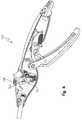
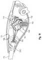
- FIG. 1is an elevated perspective view of an exemplary laparoscopic device in accordance with the instant disclosure.
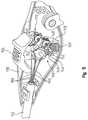
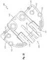
- FIG. 2is an elevated perspective view of the proximal end of the exemplary laparoscopic device of FIG. 1 .
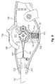
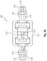
- FIG. 3is an elevated perspective view of the proximal end of the exemplary laparoscopic device of FIG. 2 , without the left side housing.
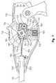
- FIG. 4is a profile view of the proximal end of the exemplary laparoscopic device of FIG. 2 , without the left side housing and without some of the internal components in order to show the axle in a distal portion of a through hole in the repositionable button.
- FIG. 5is an elevated perspective view of a distal portion of the proximal end of the exemplary laparoscopic device of FIG. 2 , without the left side housing and without the clip release wires and the draw wires, and with the pitch and yaw controls in an unlocked position.
- FIG. 6is a profile view of a distal portion of the proximal end of the exemplary laparoscopic device of FIG. 2 , without the left side housing and without the clip release wires and the draw wires, and with the pitch and yaw controls in a locked position.
- FIG. 7is a profile view of a distal portion of the proximal end of the exemplary laparoscopic device of FIG. 2 , without the left side housing and without the clip release wires and the draw wires, and with the pitch and yaw controls in the unlocked position.
- FIG. 8is a profile view of a distal portion of the proximal end of the exemplary laparoscopic device of FIG. 2 , without the left side housing, the clip release wires, the draw wires, and the yaw control.
- FIG. 9is an elevated perspective view of a distal portion of the proximal end of the exemplary laparoscopic device of FIG. 2 , without the left side housing, the clip release wires, the draw wires, and the yaw control.
- FIG. 10is an elevated perspective view of a distal portion of the proximal end of the exemplary laparoscopic device of FIG. 2 , without the left side housing, the clip release wires, the draw wires, and the control button.
- FIG. 11is an end view, from the proximal end, of an exemplary clevis of the exemplary laparoscopic device of FIG. 1 .
- FIG. 12is an end view, from the distal end, of the exemplary clevis of FIG. 11 .
- FIG. 13is a profile view of the exemplary clevis of FIG. 11 .
- FIG. 14is an elevated perspective view of the exemplary clevis of FIG. 11 .
- FIG. 15is an elevated perspective view, from a distal end, of an exemplary dual pivot joint of the exemplary laparoscopic device of FIG. 1 .
- FIG. 16is a profile view of the exemplary dual pivot joint of FIG. 15 .
- FIG. 17is an elevated perspective view, from a proximal end, of the exemplary dual pivot joint of FIG. 15 .
- FIG. 18is a top view of the exemplary dual pivot joint of FIG. 15 .
- FIG. 19is an end view, from the proximal end, of the exemplary dual pivot joint of FIG. 15 .
- FIG. 20is another elevated perspective view, from a distal end, of the exemplary dual pivot joint of FIG. 15 .
- FIG. 21is an elevated perspective view, from a proximal end, of an exemplary yoke of the exemplary laparoscopic device of FIG. 1 .
- FIG. 22is a top view of the exemplary yoke of FIG. 21 .
- FIG. 23is an underneath perspective view, from a lateral side, of the exemplary yoke of FIG. 21 .
- FIG. 24is a distal view of the exemplary yoke of FIG. 21 .
- FIG. 25is a bottom view of the exemplary yoke of FIG. 21 .
- FIG. 26is another underneath perspective view, from the opposite lateral side, of the exemplary yoke of FIG. 21 .
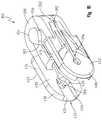
- FIG. 27is an elevated perspective view, from the proximal end, of the exemplary dual pivot joint and yoke mounted to a clip deployment device, where the view shows the both sets of connection wires, the draw wires, and the clip release wires.
- FIG. 28is an elevated perspective view, from the proximal end, of the exemplary yoke mounted to a clip deployment device, where the view shows one set of connection wires, the draw wires, and the clip release wires.
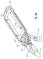
- FIG. 29is an elevated perspective view, from the proximal end, of the exemplary clevis, dual pivot joint, and yoke mounted to a clip deployment device and an occlusion clip, where the yoke is being grasped by a robotic grasper.
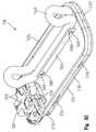
- FIG. 30is an elevated perspective view, from the distal end, of the exemplary yoke mounted to a clip deployment device, where the view is devoid of the draw wires and the clip release wires.
- FIG. 31is an underneath perspective view, from the distal end, of the exemplary yoke mounted to a clip deployment device, where the view is devoid of the draw wires and the clip release wires.
- FIG. 32is an elevated perspective view, from the proximal end, of the exemplary clip deployment device and retention dowels, where the view is devoid of the draw wires and the clip release wires.
- FIG. 33is an elevated perspective view, from the proximal end and lateral side, of the exemplary clevis, dual pivot joint, and yoke mounted to a clip deployment device and an occlusion clip, where the draw wires and the clip release wires are shown.
- FIG. 34is an elevated perspective view, from the proximal end and lateral side, of the exemplary clevis, dual pivot joint, and yoke mounted to a clip deployment device and an occlusion clip, where the draw wires, the clip release wires, and the suture loops are shown.
- FIG. 35is a magnified elevated perspective view showing the attachment between the occlusion clip and the clip deployment device, as well as the interaction of the draw wires and the clip release wires.
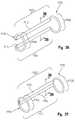
- FIG. 36is a perspective view of an exemplary clamp in an open position that may be used with the exemplary laparoscopic device of FIG. 1 .
- FIG. 37is a perspective view of the exemplary clamp of FIG. 36 in a closed position.
- FIG. 38is a cross-sectional view of the exemplary clamp of FIG. 36 in its open configuration, showing the wire member, rigid tubular members, and the urging members.
- FIG. 39is a cross-sectional view of the exemplary clamp of FIG. 37 in its closed configuration, showing the wire member, rigid tubular members, and the urging members.
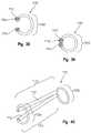
- FIG. 40is a perspective view of the exemplary clamps of FIGS. 36-39 and showing the ability to close in a non-parallel fashion.
- FIG. 41is a perspective view of the first stage of assembly of an alternate embodiment of a clamp, showing a wire member surrounded by rigid tubular members.
- FIG. 42is a perspective view of the second stage of assembly of the clamp of FIG. 41 , in which platens have been added over the rigid tubular members.
- FIG. 43is a perspective view of the claim of FIGS. 41 and 42 , once an outer fabric covering has been disposed over the entire surface of the clamp.
- the exemplary embodiments of the present disclosureare described and illustrated below to encompass surgical equipment and, more specifically, to surgical equipment that may be used in minimally invasive procedures.
- the disclosurealso relates to surgical equipment to facilitate the positioning and deployment of an atrial appendage occlusion device.
- the disclosurerelates to surgical equipment that is adapted to accommodate or work in tandem with flexible endoscopes.
- the embodiments discussed beloware exemplary in nature and may be reconfigured without departing from the scope and spirit of the present disclosure.
- the exemplary embodiments as discussed belowmay include optional steps, methods, and features that one of ordinary skill should recognize as not being a requisite to fall within the scope of the present disclosure.
- an exemplary clip deployment apparatus 100comprises a controller 110 mounted to a proximal portion of a rigid or semi-rigid conduit 112 that is relatively linear.
- the controller 110includes various controls in order to manipulate a repositionable mechanism operatively coupled to an end effector 118 , where the repositionable mechanism is mounted to a distal portion of the conduit 112 .
- the repositionable mechanismis coupled to an end effector comprising a clip deployment device 118 .
- the end effector 118may comprise any number of devices such as, without limitation, forceps, ablation rails, jaws, linear cutters, ablation pens, ablation clamps, illuminated dissectors, and non-illuminated dissectors.
- the exemplary repositionable mechanismincorporates a dual passive mechanism.
- the first passive mechanismis operative to control the pitch (i.e., up and down) of the end effector 118
- the second passive mechanismis operative to control the yaw (i.e., side to side) of the end effector.
- the controller 110is coupled to the conduit 112 in order to manipulate a repositionable mechanism operatively coupled to the end effector 118 .
- the controller 110comprises a right side housing 130 and a left side housing 132 that cooperatively define an internal cavity and corresponding openings to accommodate throughput of certain controls.
- a first of these openingsis a dorsal opening 134 that accommodates throughput of a repositionable button 136 .
- the repositionable button 136may be manipulated vertically to lock and unlock the repositionable mechanisms, as well as forward-to-rearward to lock and unlock the position of the button itself, in order to provide for or constrain lateral and vertical adjustability of the end effector 118 .
- the repositionable button 136comprises a proximal-to-distal arcuate top 138 that includes bumps and a proximal ridge to accommodate the thumb of a user being positioned on top of the button.
- the medial-to-lateral width of the arcuate top 138is generally constant and overlaps a vertical, planar appendage 142 that extends from the underside of the arcuate top.
- This vertical appendage 142has a relatively constant and minimal medial-to-lateral dimension, but includes a proximal-to-lateral dimension that tapers from a maximum where the appendage extends from the arcuate top, to a minimum where the appendage ends.
- Extending through this vertical appendage 142is a U-shaped through hole 144 that is partially occupied by an axle 164 .
- This U-shaped through hole 144allows the button 136 to be vertically repositioned with respect to the axle 164 so that active pressure is required to maintain a depressed button position when the axle is in a distal portion of the through hole.
- the usermay choose to rotate the button with respect to the axle 164 in order to seat the axle in a proximal portion of the through hole 144 , thus effectively locking the button in the depressed position.
- a usersimply rotates or pushes the button proximally to cause the axle 164 into the distal portion of the through hole 144 .
- a pair of tooth receivers 146extend outward in the medial and lateral directions from opposing sides of the appendage.
- the tooth receivers 146each include a series of longitudinal pyramidal shapes 148 that are in parallel and radially arranged in order to define a series of corresponding longitudinal pyramidal cavities 150 .
- a cylindrical projection 152At the medial end of the medial tooth receiver 146 and at the lateral end of the lateral tooth receiver 146 is a cylindrical projection 152 that is received within corresponding vertical, oblong grooves 154 on the interior of the housings 130 , 132 .
- grooves 154inhibit significant medial-to-lateral and proximal-to-distal travel of the tooth receivers 146 as the tooth receivers are vertically repositioned.
- the toothed receivers 146are vertically repositioned in a corresponding vertical manner. In this way, the movement of the toothed receivers 146 is directly attributable to the movement of the button 136 as the toothed receivers are indirectly mounted to the button via the appendage 142 .
- the button 136is biased vertically to its highest vertical position shown in FIG. 6 .
- the housings 130 , 132include parallel walls 158 that cooperate to form medial-to-lateral trench within which at least one spring 160 is seated.
- the spring 160is rated at a sufficient spring force to overcome the weight of the button 136 , appendage 142 , tooth receivers 146 , and cylindrical projections 152 to force the button to its highest vertical position. But the spring force is not so great that it requires too great a force from a user's thumb to depress the button 136 and overcome the bias of the spring 160 .
- An axle 164extends in the medial-to-lateral direction within the interior cavity cooperatively defined by the housings 130 , 132 .
- This axle 164is cylindrical in shape and includes a constant longitudinal diameter, thereby giving the axle a circular circumference.
- the medial and lateral ends of the axle 164are received within corresponding cylindrical cavities (not shown) on the interior of the housings. The depth of these cavities is not so great as to cover the majority of the axle 164 .
- the exposed cylindrical portion of the axle 164is operative to receive a pair of toothed assemblies 168 , 170 that are interposed by the appendage 142 , which itself includes a vertical, oblong orifice (not shown) to accommodate throughput of the axle and vertical travel of the appendage with respect to the axle, which has a fixed orientation.
- the toothed assemblies 168 , 170include a through cylindrical orifice 172 allowing the assemblies to rotate on the outside of the axle.
- the toothed assemblies 168 , 170are identical to each other. Accordingly, a redundant description of the second toothed assembly has been omitted in furtherance of brevity.
- the toothed assemblies 168 , 170include a wheel 176 having circumferentially distributed teeth 178 that are sized to engage a respective tooth receivers 146 and be received within the longitudinal pyramidal cavities 150 when the tooth receivers in a raised vertical position (see FIG. 6 ).
- the spring rate of the spring 160is chosen to allow the tooth receivers 146 to be depressed by forces applied to the toothed assemblies 168 , 170 above a predetermined threshold.
- a high load applied to the end effector in any one directionmay result in repositioning of one or both of the toothed assemblies 168 , 170 , thereby causing a wheel 176 and its teeth 178 to rotate and correspondingly depress against the corresponding tooth receiver 146 , which depresses against the spring 160 to compress the spring, thus allowing one or both wheels to rotate to avoid breaking any of the components.
- the wheel 176has a generally uniform width but for a pair of outgrowths 180 , 182 .
- the first outgrowth 180is generally centered radially with respect to the wheel and partially defines the through orifice 172 that receives the axle 164 .
- This first outgrowth 180is semicircular in shape extends medially from the wheel 176 and includes a corresponding top and bottom arcuate surfaces 184 , 186 that are radially inset with respect to the wheel. These arcuate surfaces 184 , 186 act as camming surfaces for respective connection wires 188 , 190 that extend from the second outgrowth 182 .
- the first outgrowth 180also includes a pair of vertical flanges 194 that extend from the arcuate surfaces 184 , 186 and cooperate with the circumferential ends of the wheels in order to provide medial and lateral guides for the connection wires 188 , 190 so that the connection wires stay therebetween.
- the second outgrowth 182is proximally oriented with respect to the first outgrowth 180 and includes a rectangular profile with a pair of L-shaped walls 192 and floor 196 cooperating to define an internal cavity. An opening (not shown) extends through the floor and into the cavity. This opening receives a fastener (such as a screw) 200 around which the connection wires 188 , 190 are wound and secured in place.
- the fastener 200is also recessed within the cavity so that the L-shaped walls 192 extend laterally beyond the end of the fastener. Accordingly, the connection wires 188 , 190 extending from the fastener are threaded through a gap between the L-shaped walls 192 , with one of the wires being threaded over the top arcuate surface 184 , while the second wire is threaded under the bottom arcuate surface 186 . Thereafter, the wires 188 , 190 extend distally and taper to extend through a respective eyelet opening at the proximal end of the conduit 112 .
- Each of the toothed assemblies 168 , 170is independently rotatably repositionable with respect to one another.
- the first toothed assembly 168is operative provide part of a passive repositionable mechanism in order to control the pitch (i.e., up and down) of the end effector 118
- the second toothed assembly 170is operative to provide part of a passive repositionable mechanism in order to control the yaw (i.e., side to side) of the end effector.
- the spring 160when the button 136 is not depressed, the spring 160 is operative to bias the toothed receivers 146 into engagement with the teeth 178 of the toothed assemblies 168 , 170 , thereby inhibiting rotation of the toothed assemblies around the axle 164 .
- the end effector 118cannot be repositioned in the vertical direction (i.e., affecting pitch) or in the medial-to-lateral direction (i.e., affecting yaw).
- the end effector 118 locked in positionwhen the tooth assemblies 168 , 170 are locked in position (see FIG. 6 ), so too is the end effector 118 locked in position.
- a userwould depress the button 136 .
- the toothed receivers 146are operative to further compress the spring 160 and disengage the toothed assemblies 168 , 170 .
- the longitudinal pyramidal shapes 148 and corresponding longitudinal pyramidal cavities 150no longer engage the teeth 178 of the toothed assemblies 168 , 170 , thereby allowing rotation of the toothed assemblies around the axle 164 .
- connection wires 188 , 190 linking the end effector 118 and the toothed assembliesmay be repositioned, which allows the end effector to be freely repositionable in the vertical direction (i.e., affecting pitch) and in the medial-to-lateral direction (i.e., affecting yaw).
- the userwould discontinue depressing the button 136 to lock in the relative vertical and medial-to-lateral positions.
- the spring 160forces the toothed receivers 146 upward and into engagement with the toothed assemblies 168 , 170 .
- the toothed assemblies 168 , 170include teeth 178 that engage the longitudinal pyramidal shapes 148 of the toothed receivers 146 , the spring 160 will direct the toothed receivers upward and cause the toothed assemblies to possibly rotate slightly about the axle 164 so that the teeth are fully received within the longitudinal pyramidal cavities 150 . If the position of the end effector 118 is such that the teeth 178 are aligned with the longitudinal pyramidal cavities 150 , then the vertical and medial-to-lateral positions will be precisely maintained because of the tension on the connection wires 188 , 190 .
- the vertical and medial-to-lateral positionswill be changed as the toothed assemblies 168 , 170 rotate slightly about the axle 164 so that the teeth are fully received within the longitudinal pyramidal cavities 150 .
- the vertical and medial-to-lateral positionswill be precisely maintained because of the tension on the connection wires 188 , 190 .
- a distal portion of the right side housing 130includes a pair of detents 202 that engage the conduit 112 . These detents 202 inhibit longitudinal movement of the conduit 112 with respect to the controller 110 . Both detents 202 extend in parallel to one another and extend from an interior circumferential surface of the right side housing 130 .
- the right and left side housings 130 , 132cooperate to delineate a handle mechanism port 210 and a proximal port 212 open to the interiors of the respective housings.
- the handle mechanism port 210accommodates throughput of a portion of a handle mechanism 218 that comprises a repositionable lever 220 , a drive plate 222 , a return spring 224 , and a wire retainer 226 .
- the wire retainer 226is concurrently coupled to draw wires 228 and the drive plate 222 so that movement of the lever 220 is operative to open and close an occlusion clip 1160 (compare FIGS. 29 and 34 ), such as during an atrial appendage occlusion clip deployment surgical procedure.
- the repositionable lever 220includes an arcuate, ventral gripping surface that may include a series of convex bumps longitudinally spaced apart to facilitate gripping by a user. Opposite the ventral gripping surface is a corresponding interior surface from which a pair of spaced apart, parallel vertical walls 230 , 232 extend.
- the vertical walls 230 , 232are also connected to one another via a plurality of cross walls 234 .
- the vertical walls 230 , 232each include a distal upstanding loop 238 that provides a through opening in the medial-to-lateral direction to receive a axle 240 extending from the right side housing 130 around which the lever 220 rotates.
- the walls 230 , 232Extending distally from the loop 238 , the walls 230 , 232 include a circular opening extending in the medial-to-lateral direction that receives a pin 244 in order to repositionably mount the drive plate 222 to the lever 220 .
- the exemplary drive plate 222comprises an arcuate, flat plate sized to fit between the walls 230 , 232 of the lever 220 .
- a distal end of the plate 222includes an opening to receive the pin 244 .
- Extending proximally from the openingis an elongated, arcuate opening 246 adapted to receive a dowel 248 extending from the interior of the right side housing 130 .
- the dowel 248is repositioned with respect to the opening 246 as the lever 220 repositions the drive plate 222 .
- the openingis partially defined by a lip 250 that acts to retain the dowel 248 in a static position after the lever 220 is fully closed.
- the proximal end of the drive plate 222includes an orifice 252 that receives a portion of the spring 224 in order to bias the lever 220 to the open position shown in FIG. 3 .
- the opposing end of the spring 224is mounted to a dowel 254 that extends from the interior of the right side housing 220 .
- the controller 110also includes a removable stem 260 that is seated within the proximal port 212 of the housings 130 , 132 .
- the removable stem 260is coupled to one or more clip release wires 292 (in this case, two clip release wires) that act to disconnect an occlusion clip from the clip deployment device 118 .
- the stem 260may be removed from the proximal end of the controller 110 , thereby drawing the release wire(s) proximally and disconnecting the occlusion clip from the clip deployment device 118 .
- the stem 260is secured within the proximal port 212 via a friction fit that may be overcome by the user applying pressure to the stem to move it proximally with respect to the controller 110 . But it is also within the scope of the disclosure to use detents or other affirmative release mechanisms to release the stem 260 from the controller 110 .
- the controller 110is mounted to a rigid or semi-rigid conduit 112 that is relatively linear and has a relatively constant circular cross section.
- the conduit 112is fabricated from stainless steel and includes a proximal circular opening and a distal circular opening.
- the proximal circular openingprovides access between the interior of the conduit 112 and the interior of the controller 110 . More specifically, the hollow interior of the conduit 112 accommodates throughput of the connection wires 188 , 190 and the clip release wires 292 .
- the conduit 112includes a proximal section having a pair of rectangular, arcuate cut-outs providing respective recesses for the detents 202 of the right side housing 130 to occupy and mount the conduit 112 to the housings 130 , 132 .
- conduit 112may be relatively linear but include two additional orifices that accommodate a separate conduit (not shown) adapted to provide a separate avenue for an exploratory tool.
- Exemplary exploratory tools for use with the instant semi-rigid conduitinclude, without limitation, forceps, ablation rails, jaws, linear cutters, ablation pens, ablation clamps, illuminated dissectors, and non-illuminated dissectors.
- the exemplary exploratory toolmay be used in combination with the end effector, which is manipulated by the repositionable mechanism.
- a distal portion of the exemplary repositionable mechanismcomprises a clevis 302 having a partially enclosed proximal section 304 that delineates a cavity 306 receives a distal section of the conduit 112 to mount the clevis to the conduit.
- a clevis 302having a partially enclosed proximal section 304 that delineates a cavity 306 receives a distal section of the conduit 112 to mount the clevis to the conduit.
- On the interior of the cavity 306are four equidistantly, radially spaced apart ribs 308 that extend longitudinally and in parallel to one another.
- the ribs 308operate to decrease the diameter of the cavity 306 so that the ribs contact the exterior, circumferential surface of the conduit 112 to mount the conduit to the clevis 302 via a friction fit.
- Each of the ribs 308terminates distally at a wall 310 extending normal to the longitudinal direction of the ribs.
- the wall 310includes a series of orifices 312 , 314 , 316 that accommodate throughput of the connection wires 188 , 190 and the clip release wires 292 .
- the first orifice 312accommodates throughput of the first connection wire 188
- the second orifice 314accommodates throughput of the clip release wires 292
- the third orifice 316accommodates throughput of the second connection wire 190 .
- the wall 310also bridges the proximal section 304 and a distal section 320 of the clevis 302 .
- Te distal section 320 of the clevis 302includes a pair of distal projections 324 , 326 extending away from the wall 310 to create a ceiling and floor.
- the projections 324 , 326are oriented to provide a gap therebetween extending in proximal-to-distal direction and in a medial-to-lateral direction.
- Each projection 324 , 326includes a mildly convex outer surface 330 that is jointed by a peripheral surface 332 that is rounded to at the distal tip.
- the peripheral surfaces 332are jointed by respective exterior side surfaces 334 .
- Each projection 324 , 326includes a depression 336 that originates at the distal tip of the clevis 302 and extends proximally.
- the bounds of the depression 336are delineated by a planar bottom surface 340 , a horseshoe (i.e., semicircular) peripheral surface 342 , and a planar base surface 344 .
- the arcuate contour of the peripheral surface 342is operative to allow a dual pivot joint to 350 to pivot in a single plane with respect to the clevis 302 .
- the dual pivot joint 350comprises a proximal section 352 having a pair of plateaus 354 that extend in opposite directions from one another.
- Each plateau 354includes a teardrop shaped circumferential surface 356 with the rounded portion of the surface adapted to have an arcuate curvature that approximates the arcuate curvature of the peripheral surface 342 of the clevis 302 .
- the plateaus 354are interposed by a platform 358 having opposed, generally planar parallel surfaces 360 .
- the dual pivot joint 350may pivot with respect to the clevis 302 by the plateaus 354 pivoting or rotating with respect to the peripheral surface 342 , while the planar surfaces 360 contact the planar base surfaces 344 of the clevis to limit significant vertical play between the clevis and dual pivot joint.
- the pointed aspect of each circumferential surface 356cooperates with the straight walls of the peripheral surface 342 of the clevis 302 to provide stops that limit the pivotal motion of the dual pivot joint 350 with respect to the clevis 302 to no more than fifty-five degrees from center (total range of motion of approximately 110 degrees).
- the range of travelmay be increased by increasing the angle of the pointed aspect of the circumferential surfaces.
- the range of travelmay be decreased by decreasing the angle of the pointed aspect of the circumferential surfaces.
- a proximal aspect of the platform 358is rounded and includes two pair of arcuate walls 364 that are spaced apart from one another to create a gap 368 that tapers distally to create a cylindrical through hole 376 extending into the interior of a distal aspect 370 of the dual pivot joint.
- the tapered feature of each gap 368is partially defined by a pair of angled faces 372 that operate to allow the connection wires 188 to be fed in between the walls 364 , through the cylindrical hole 376 and into the interior of the distal aspect, where the wires are ultimately connected to a yoke 380 .
- each gap 368ensures that the connection wires 188 do not become bound up by pivoting action of the dual pivot joint 350 with respect to the clevis 302 . But for the tapered nature of the gap 368 , pivoting action beyond center of the dual pivot joint 350 with respect to the clevis 302 would cause the path of the connection wires 188 to be lengthened, thereby resulting in pivoting of the yoke 380 with respect to the dual pivot joint.
- a centered gap 384Interposing the two pair of arcuate walls 364 and respective gaps 368 is a centered gap 384 that also tapers distally to create a through hole 386 having a rectangular, rounded cross-section that extends into the interior of the distal aspect 370 of the dual pivot joint.
- the tapered feature of this centered gap 384is partially defined by a pair of angled faces 388 that operate to allow the draw wire 228 and clip release wires 292 to be fed in between the walls 364 , through the hole 386 , and into the interior of the distal aspect, where the wires are ultimately fed through a clip deployment frame 520 .
- this gap 384ensures that the draw wire 228 and clip release wires 292 do not become bound up by pivoting action of the dual pivot joint 350 with respect to the clevis 302 . But for the tapered nature of the gap 384 , pivoting action beyond center of the dual pivot joint 350 with respect to the clevis 302 would cause the path of the draw wire 228 and clip release wires 292 to be lengthened, thereby potentially resulting in premature release of the clip 1160 and opening of the clip.
- Adjoining the angled faces 388is an arcuate wall 390 that curves around a lateral edge of the proximal section 352 and extends into the interior of the distal section 370 .
- the arcuate wall 390is inset within the proximal section 352 to create a lateral trench 392 on the right and left sides.
- Each lateral trench 392ends distally proximate a lateral, longitudinal opening 396 extending through right and left side paddles 402 .
- This pair of lateral trenches 390respectively receives one of the connection wires 190 so that the ends of each connection wire extend into the interior of the distal section 370 .
- Each end of the connection wire 190is enlarged to prohibit the end from passing through the longitudinal opening 396 .
- the longitudinal opening 396is sized to allow throughput of the connection wire 190 along the longitudinal length of the connection wire, but is sized to prohibit throughput of the enlarged end of the connection wire.
- tensioncan be applied the connection wires 190 in order to cause the dual pivot joint 350 to pivot with respect to the clevis 302 .
- the dual pivot jointpivots to the right side.
- the dual pivot jointpivots to the left side.
- the right side paddle 402is a mirror image of the left side paddle. Accordingly, for purposes of explanation, only a single paddle will be described.
- Each paddle 402includes a lateral exterior surface 406 that is substantially planar but for a pair of projections 408 that are spaced apart from one another by the longitudinal opening 396 extending therebetween.
- Each projection 408includes a linear aspect 410 that extends in parallel with the longitudinal opening 396 and a curved aspect 412 .
- the curved aspect 412has a curvature that mirrors the arcuate motion of the yoke 380 .
- the paddle 402includes a vertical height extending above and below the proximal section 352 .
- the top and bottom surfaces 414 of the paddle 402are generally planar and are bridged by a curved circumferential surface 418 .
- the lateral or widthwise dimension of the paddle 402is substantially uniform, from proximal to distal, but for an interior depression 420 that is open on the distal end of the paddle and extends proximally to intersect the longitudinal opening 396 .
- the depression 420is partially defined by a planar wall 424 that is perpendicular to a second planar wall 426 with an arcuate transition therebetween.
- a third wall 428is also perpendicular to the planar wall 424 and includes an arcuate profile that corresponds to the arcuate profile of a plateau of the yoke 380 .
- each paddle 402intersects a pair of rectangular projections 432 .
- Each rectangular projection 432includes a distal wall 436 that is arcuate from right to left. The arcuate curvature of the distal wall generally tracks the arcuate profile of a portion of the yoke 380 .
- the yoke 380comprises a hollow box having a roof 440 , a floor, 442 , a right side wall 444 , and a left side wall 446 .
- the front of the boxis open and reveals the interior cavity.
- Extending laterally outward from the right and left side walls 444 , 446are respective right and left wings 448 , 450 .
- Each wing 448 , 450includes a pair of circumferential projections 452 that extend vertically therethrough to protrude above and below the wing.
- the projectionsare sized and spaced apart to facilitate grasping of the yoke 380 by a robotic grasper 456 (see FIG. 29 ).
- a distal portion of the each wing 448 , 450is generally flush with walls defining a distal recess 458 within the respective right and right and left side walls 444 , 446 .
- the distal recessis sized to accommodate partial insertion of the clip deployment frame 520 .
- the right wing 448is laterally widest at its distal end and tapers in a widthwise dimension, bounded by an arcuate peripheral surface 460 .
- the proximal portion of the right wing 448extends proximally beyond the hollow box and includes a planar guide 464 that is parallel to a right side plateau 466 extending from a proximal section 468 of the yoke 380 .
- a hole 470extends through the planar guide 464 and extends into communication with an underneath trench 472 formed into the bottom surface 474 of the right wing. This underneath trench 472 terminates distally at the distal end of the right wing 448 .
- one of the clip deployment wires 292is fed past the proximal section 468 , through the hole 470 , and along this underneath trench 472 to exit and extend distally from the trench.
- the proximal section 468includes right and left side plateaus 466 , 476 that extend in opposite directions from one another.
- Each plateau 466 , 476includes a teardrop shaped circumferential surface 478 with the rounded portion of the surface adapted to have an arcuate curvature that approximates the arcuate curvature of the third wall 428 of the dual pivot joint 350 .
- the plateaus 466 , 476are interposed by a platform. 482 having opposed, generally planar parallel surfaces 484 . Accordingly, the yoke 380 may pivot with respect to the dual pivot joint 350 by the plateaus 466 , 476 pivoting or rotating with respect to the third wall 428 .
- each circumferential surface 478cooperates with the straight walls of the second planar wall 426 of the dual pivot joint 350 to provide stops that limit the pivotal motion of the dual pivot joint with respect to the yoke to no more than fifty-five degrees from center (total range of motion of approximately 110 degrees).
- the range of travelmay be increased by increasing the angle of the pointed aspect of the circumferential surfaces.
- the range of travelmay be decreased by decreasing the angle of the pointed aspect of the circumferential surfaces.
- a proximal aspect of the platform 482is rounded and includes two pair of arcuate, solid walls 486 that are spaced apart from one another to create a gap 488 that tapers distally to create a through hole 490 extending into the interior of the hollow box.
- the tapered feature of this gap 488is partially defined by a pair of angled faces that operate to allow the draw wires 228 to be fed in between the walls 486 , through the hole 490 and fed through the clip deployment frame 520 , where the wires are ultimately connected to an occlusion clip 1160 (see FIG. 30 ).
- the tapered nature of this gap 488ensures that the draw wires 228 do not become bound up by pivoting action of the yoke 380 with respect to the dual pivot joint 350 .
- each connection wire 188is received within the respective grooves so that the distal ends of the connection wires extend into the interior of the hollow box.
- Each end of the connection wires 188is enlarged to prohibit the end from passing through the top and bottom holes 498 , 500 .
- the holes 498 , 500are sized to allow throughput of the connection wires 188 , but are sized to prohibit throughput of the enlarged end of the connection wires.
- tensioncan be applied the connection wires 188 in order to cause the yoke 380 to pivot with respect to the dual pivot joint 350 .
- the yokepivots upward with respect to the dual pivot joint 350 .
- the bottom connection wire 188the yoke pivots downward with respect to the dual pivot joint 350 .
- the left wing 450Adjacent the platform 482 , on the left side, is the left wing 450 .
- the left wing 450is laterally widest at its distal end and tapers in a widthwise dimension, bounded by an arcuate peripheral surface 504 .
- the proximal portion of the left wing 450extends proximally beyond the hollow box and includes a planar guide 506 that is parallel to the left side plateau 476 .
- a hole 508extends through the planar guide 506 and extends into communication with an underneath trench 510 formed into the bottom surface 512 of the left wing. This underneath trench 510 terminates prior to reaching the distal end of the left wing 450 .
- the trench 510terminates and feeds into a distal tunnel 514 that extends through a distal portion of the left wing 450 .
- a second of the clip deployment wires 292is fed past the proximal section 468 , through the hole 508 , along this underneath trench 510 , through the tunnel 514 and exits distally from the tunnel.
- the clip deployment device 118is partially received within the interior of the hollow box.
- the clip deployment device 118includes a rectangular frame 520 having parallel longitudinal sides 524 , 526 that are connected to one another via a distal cross-member 527 with rounded corners therebetween.
- each parallel side 524 , 526includes a substantially planar interior wall 528 and a concave exterior wall 530 , opposite the interior wall.
- the concave nature of the exterior wall 530creates a longitudinal channel, with one exterior channel receiving a first of the clip deployment wires 292 .
- the parallel sides 524 , 526may include one or more through orifices extending through the interior and exterior walls 528 , 530 .
- the proximal end of the rectangular frame 522includes a pair of rounded corners that extend from the parallel sides 524 , 526 .
- Each rounded corner on the proximal endforms part of an S-shaped retainer 540 , 542 that is partially received within the hollow box interior of the yoke 380 .
- both S-shaped retainers 540 , 542comprise a first rounded corner that transitions into a straight segment 546 , which transitions into a semicircular segment 548 .
- the S-shaped retainers 540 , 542are mirror images of one another, except that the one retainer 540 includes an orifice 550 that extends through the interior and exterior surfaces and along the majority of the straight and semicircular segments 546 , 548 .
- two dowels 560are inserted through corresponding holes 562 in the top and bottom surfaces 440 , 442 of the yoke.
- the holes 562are sized to retain the dowels 560 in position.
- the S-shaped retainers 540 , 542are inserted into the interior of the yoke 380 .
- the vertical dimension of the S-shaped retainers 540 , 542is such that the retainers are wedged in between the top and bottom walls 440 , 442 of the yoke 380 .
- the collective lengthwise dimension of the S-shaped retainers 540 , 542is such that the retainers are wedged in between the right and left side walls 444 , 446 . In this manner, even absent the dowels 560 , there is not significant play between the clip deployment device 118 to the yoke 380 in the vertical and lateral directions.
- the dowels 560are inserted through the holes 562 after the semicircular segment 548 of each S-shaped retainers 540 , 542 is positioned to partially outline an imaginary cylinder extending through the holes. This locks the S-shaped retainers 540 , 542 in position with respect to the yoke 380 , thereby mounting the clip deployment device 118 to the yoke.
- the orifice 550 of the one retainer 540provides an egress hole through which a second of the clip deployment wires 292 passes through.
- the second of the clip deployment wires 292extends into the interior of the rectangular frame 522 and passes longitudinally along the exterior of an elongated deployment plate 566 .
- the deployment plate 566includes a pair of orifices 568 near the proximal and distal ends of the plate. As will be discussed in more detail hereafter, the orifices 568 receive suture loops 570 that are captured by the clip deployment wire 292 passing therethrough.
- the orifice 550also provides an egress hole through which the draw wires 228 pass through.
- the draw wires 228are initially routed into the interior of the rectangular frame 522 to pass through an orifice 572 in one of the proximal rounded corners. Both wires 228 extend along the longitudinal channel of one of the parallel sides 524 created by the concave exterior wall 530 .
- One of the wirespasses through a first proximal orifice 576 in the first parallel side 524 , while the second wire continues to extend along the longitudinal channel until reaching a second distal orifice 578 .
- Both wires 228then extend into the interior of the rectangular frame 522 and pass perpendicularly through a second set of orifices 580 of the elongated deployment plate 566 .
- This second set of orifices 580are inset with respect to the pair of orifices 568 near the proximal and distal ends of the plate.
- the wiresare joined and create a closed loop coupled to the deployment plate 566 .
- FIGS. 36-38show one embodiment of a left atrial appendage occlusion clamp 1110 in an open position with spaced apart rigid clamping portions 1102 , 1104 and resilient or elastic urging members 1106 , 1108 at opposite ends of each clamping portion 1102 , 1104 .
- Clamping portions 1102 , 1104may be tubular, and both clamping portions 1102 , 1104 may be at least substantially parallel to each other when arrest, i.e., when they are not being used to clamp tissue.
- Clamping portions 1102 , 1104may also be of substantially equal length or of different length, and each may be of larger outer diameter than the wire that may be used to form each of the urging members 1106 , 1108 .
- the wire forming urging members 1106 , 1108can extend through the hollow interiors of the clamping portions 1102 , 1104 .
- the urging members 1106 , 1108are each shaped as a loop.
- the planes defined by the looped configuration of each of the urging members 1106 , 1108may be substantially parallel to each other and, in turn, substantially perpendicular to each of the clamping portions 1102 , 1104 .
- other angular orientationsare possible as well.
- FIGS. 37-39show the same clamp 1110 of FIGS. 36-38 with the clamping portions 1102 , 1104 in their normally biased together positions. Contact between the clamping portions 1102 , 1104 may occur initially along their entire parallel lengths as shown. Of course, when clamping portions 1102 , 1104 are covered in fabric or other material as later described, contact may occur between the fabric or other material instead.
- FIGS. 36-39only the structure and relative positions of the rigid members 1102 , 1104 and urging members 1106 , 1108 are shown. The final assembly is depicted in FIGS. 40-42 which, although describing a slightly different embodiment, show the general steps in the construction of each embodiment.
- the clamping portions 1102 , 1104may be made from rigid tubes 1112 , 1114 of a rigid metal such as titanium disposed over a wire member 1116 .
- titaniumis used for its compatibility with MRI imaging, its biocompatibility and its galvanic compatibility with the wire member 1116 when the wire member 1116 is formed from superelastic materials such as a nickel titanium alloy.
- This embodiment and the other embodiments disclosed hereinmay use a superelastic material such as a nickel titanium alloy to form the urging members 1106 , 1108 .
- Superelastic propertieswill allow the material to be greatly extended to open the clamping portions 1106 , 1108 of the clamp 1110 without permanently deforming the material.
- the rigid tubular members 1112 , 1114 of this embodimentare mechanically fastened to the underlying wire member 1116 preferably by mechanically swaging the titanium tubes 1112 , 1114 to the wire members 1116 .
- a single, continuous wire memberis shown directed through both clamping portions 1102 , 1104 and urging members 1106 , 1108 , the clamp 1110 of this embodiment may also be made with two or more wires, or with any other suitable components.
- the clamp 1110can also apply force to the anatomical structure in a nonparallel clamping fashion. This allows the clamp 1110 to accommodate non-uniform tissue thickness over the length of the clamping portions 1102 , 1104 .
- the nonparallel clampingcan originate from either side of the clamp 1110 .
- the non-parallel clamping feature of this embodimentallows the clamp 1110 to accommodate a wide range of hollow anatomical structures with varying wall thicknesses throughout its length and breadth.
- trabeculaesome anatomical structures such as atrial appendages of the heart have internal structures called trabeculae, which are non-uniform and very often cause variable thicknesses across one or more of their dimensions.
- Nonuniform clampingtherefore, can be advantageous in this application for this reason or for other reasons.
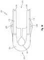
- FIG. 41shows an alternate embodiment of a clamp 1160 including two urging members 1166 , 1168 shaped to resemble a letter “U” instead of the more circular loop configuration of the embodiment of FIGS. 36-39 .
- the U-shaped urging members 1166 , 1168 of clamp 1160may also lie in planes generally parallel to each other and perpendicular to the axes of the clamping portions 1162 , 1164 .
- FIG. 41shows a first stage of assembly of the clamp 1160 , where the rigid tubular members 1163 , 1165 are joined with the superelastic wire member 1161 .
- tubular members 1163 , 1165may not necessarily need to be bonded to wire member 1161 at all.
- rigid tubular members 1163 , 1165could take on many different cross sectional shapes. Cross-sectional shapes such as ovals, triangles or rectangles with rounded edges could be preferable and may eliminate the addition of the load spreading platens 1167 , 1169 shown in FIG.
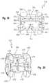
- FIG. 42shows the next step in the assembly of the clamp.
- Load spreading platens 1167 , 1169made of plastic or other biocompatible material such as urethane, may be slipped over the titanium or other suitable material tubing that forms rigid tubular members 1163 , 1165 , to provide a resilient surface 1173 to spread the load out onto a larger surface area, thereby preventing point source loading of the tissue which might otherwise result in cutting of the tissue before it has had a chance to become internally fused.
- the platens 1167 , 1169can be assembled and applied over the rigid tubular members 1163 , 1165 prior to the swaging step or platens 1167 , 1169 can alternatively be manufactured in such a way so as to have a longitudinal split which allows the material to be opened and forced onto the rigid tubular members 1163 , 1165 .
- FIG. 43shows the clamp 1160 after a fabric cover material 1174 made of material such as polyester has been sewn around the clamping portions 1162 , 1164 and urging members 1166 , 1168 .
- a fabric cover material 1174made of material such as polyester has been sewn around the clamping portions 1162 , 1164 and urging members 1166 , 1168 .
- this material or any other similar materialsmay be used as a full or partial covering in any of the disclosed embodiments.
- Such a materialis preferably suitable to engage the tissue of the anatomical structure being clamped as well as that of surrounding areas.
- the material 1174is circular warp knit fabric tube, with a diameter of approximately 4 to 5 mm and made from a combination of 4/100, 2/100 and 1/100 textured polyester.
- the material 1174may also be heat-treated to cause a velour effect.
- the fabric or other material 1174is furthermore sewn or otherwise applied over the urging members 1166 , 1168 .
- fabric pieces 1177may be attached at opposite respective ends of clamping portions 1162 , 1164 to prevent any part of the engaged anatomical structure from escaping the annular occlusion area between the clamping portions 1162 , 1164 .
- fabric pieces 1177act as tissue blocking members or dams at opposite ends of the clamp. This or another tissue blocking feature may also be implemented into any other embodiment. This is desirable as it minimizes the probability of unintentionally leaving any part of the engaged anatomical structure unclamped.
- the material 1177like material 1174 , can also promote tissue in-growth.
Landscapes
- Health & Medical Sciences (AREA)
- Surgery (AREA)
- Life Sciences & Earth Sciences (AREA)
- Heart & Thoracic Surgery (AREA)
- Nuclear Medicine, Radiotherapy & Molecular Imaging (AREA)
- Vascular Medicine (AREA)
- Engineering & Computer Science (AREA)
- Biomedical Technology (AREA)
- Reproductive Health (AREA)
- Medical Informatics (AREA)
- Molecular Biology (AREA)
- Animal Behavior & Ethology (AREA)
- General Health & Medical Sciences (AREA)
- Public Health (AREA)
- Veterinary Medicine (AREA)
- Surgical Instruments (AREA)
Abstract
Description
Claims (18)
Priority Applications (7)
| Application Number | Priority Date | Filing Date | Title |
|---|---|---|---|
| US13/355,169US9282973B2 (en) | 2012-01-20 | 2012-01-20 | Clip deployment tool and associated methods |
| PCT/US2013/022600WO2013110089A1 (en) | 2012-01-20 | 2013-01-22 | Clip deployment tool and associated methods |
| EP13738225.5AEP2804544B1 (en) | 2012-01-20 | 2013-01-22 | Surgical clip deployment tool |
| US15/014,314US10238398B2 (en) | 2012-01-20 | 2016-02-03 | Clip deployment tool and associated methods |
| US16/363,085US20190216465A1 (en) | 2012-01-20 | 2019-03-25 | Clip deployment tool and associated methods |
| US17/381,022US11883037B2 (en) | 2012-01-20 | 2021-07-20 | Clip deployment tool and associated methods |
| US18/410,718US12295587B2 (en) | 2012-01-20 | 2024-01-11 | Clip deployment tool and associated methods |
Applications Claiming Priority (1)
| Application Number | Priority Date | Filing Date | Title |
|---|---|---|---|
| US13/355,169US9282973B2 (en) | 2012-01-20 | 2012-01-20 | Clip deployment tool and associated methods |
Related Child Applications (1)
| Application Number | Title | Priority Date | Filing Date |
|---|---|---|---|
| US15/014,314ContinuationUS10238398B2 (en) | 2012-01-20 | 2016-02-03 | Clip deployment tool and associated methods |
Publications (2)
| Publication Number | Publication Date |
|---|---|
| US20130190777A1 US20130190777A1 (en) | 2013-07-25 |
| US9282973B2true US9282973B2 (en) | 2016-03-15 |
Family
ID=48797821
Family Applications (5)
| Application Number | Title | Priority Date | Filing Date |
|---|---|---|---|
| US13/355,169Active2034-06-08US9282973B2 (en) | 2012-01-20 | 2012-01-20 | Clip deployment tool and associated methods |
| US15/014,314Active2032-09-04US10238398B2 (en) | 2012-01-20 | 2016-02-03 | Clip deployment tool and associated methods |
| US16/363,085AbandonedUS20190216465A1 (en) | 2012-01-20 | 2019-03-25 | Clip deployment tool and associated methods |
| US17/381,022Active2032-06-30US11883037B2 (en) | 2012-01-20 | 2021-07-20 | Clip deployment tool and associated methods |
| US18/410,718ActiveUS12295587B2 (en) | 2012-01-20 | 2024-01-11 | Clip deployment tool and associated methods |
Family Applications After (4)
| Application Number | Title | Priority Date | Filing Date |
|---|---|---|---|
| US15/014,314Active2032-09-04US10238398B2 (en) | 2012-01-20 | 2016-02-03 | Clip deployment tool and associated methods |
| US16/363,085AbandonedUS20190216465A1 (en) | 2012-01-20 | 2019-03-25 | Clip deployment tool and associated methods |
| US17/381,022Active2032-06-30US11883037B2 (en) | 2012-01-20 | 2021-07-20 | Clip deployment tool and associated methods |
| US18/410,718ActiveUS12295587B2 (en) | 2012-01-20 | 2024-01-11 | Clip deployment tool and associated methods |
Country Status (3)
| Country | Link |
|---|---|
| US (5) | US9282973B2 (en) |
| EP (1) | EP2804544B1 (en) |
| WO (1) | WO2013110089A1 (en) |
Cited By (55)
| Publication number | Priority date | Publication date | Assignee | Title |
|---|---|---|---|---|
| US20160022464A1 (en)* | 2001-08-27 | 2016-01-28 | Boston Scientific Scimed, Inc. | Positioning tools and methods for implanting medical devices |
| US20160151072A1 (en)* | 2012-01-20 | 2016-06-02 | Atricure, Inc. | Clip deployment tool and associated methods |
| US10639032B2 (en) | 2017-06-30 | 2020-05-05 | Covidien Lp | Endoscopic surgical clip applier including counter assembly |
| US10653429B2 (en) | 2017-09-13 | 2020-05-19 | Covidien Lp | Endoscopic surgical clip applier |
| US10660723B2 (en) | 2017-06-30 | 2020-05-26 | Covidien Lp | Endoscopic reposable surgical clip applier |
| US10660651B2 (en) | 2016-10-31 | 2020-05-26 | Covidien Lp | Endoscopic reposable surgical clip applier |
| US10675112B2 (en) | 2017-08-07 | 2020-06-09 | Covidien Lp | Endoscopic surgical clip applier including counter assembly |
| US10675043B2 (en) | 2017-05-04 | 2020-06-09 | Covidien Lp | Reposable multi-fire surgical clip applier |
| US10702279B2 (en) | 2015-11-03 | 2020-07-07 | Covidien Lp | Endoscopic surgical clip applier |
| US10702280B2 (en) | 2015-11-10 | 2020-07-07 | Covidien Lp | Endoscopic reposable surgical clip applier |
| US10722236B2 (en) | 2017-12-12 | 2020-07-28 | Covidien Lp | Endoscopic reposable surgical clip applier |
| US10722235B2 (en) | 2017-05-11 | 2020-07-28 | Covidien Lp | Spring-release surgical clip |
| US10743887B2 (en) | 2017-12-13 | 2020-08-18 | Covidien Lp | Reposable multi-fire surgical clip applier |
| US10758245B2 (en) | 2017-09-13 | 2020-09-01 | Covidien Lp | Clip counting mechanism for surgical clip applier |
| US10765431B2 (en) | 2016-01-18 | 2020-09-08 | Covidien Lp | Endoscopic surgical clip applier |
| US10786263B2 (en) | 2017-08-15 | 2020-09-29 | Covidien Lp | Endoscopic reposable surgical clip applier |
| US10786262B2 (en) | 2017-08-09 | 2020-09-29 | Covidien Lp | Endoscopic reposable surgical clip applier |
| US10786273B2 (en) | 2018-07-13 | 2020-09-29 | Covidien Lp | Rotation knob assemblies for handle assemblies |
| US10806463B2 (en) | 2011-11-21 | 2020-10-20 | Covidien Lp | Surgical clip applier |
| US10806464B2 (en) | 2016-08-11 | 2020-10-20 | Covidien Lp | Endoscopic surgical clip applier and clip applying systems |
| US10828036B2 (en) | 2017-11-03 | 2020-11-10 | Covidien Lp | Endoscopic surgical clip applier and handle assemblies for use therewith |
| US10828044B2 (en) | 2015-03-10 | 2020-11-10 | Covidien Lp | Endoscopic reposable surgical clip applier |
| US10835341B2 (en) | 2017-09-12 | 2020-11-17 | Covidien Lp | Endoscopic surgical clip applier and handle assemblies for use therewith |
| US10835260B2 (en) | 2017-09-13 | 2020-11-17 | Covidien Lp | Endoscopic surgical clip applier and handle assemblies for use therewith |
| US10849630B2 (en) | 2017-12-13 | 2020-12-01 | Covidien Lp | Reposable multi-fire surgical clip applier |
| US10905425B2 (en) | 2015-11-10 | 2021-02-02 | Covidien Lp | Endoscopic reposable surgical clip applier |
| US10932791B2 (en) | 2017-11-03 | 2021-03-02 | Covidien Lp | Reposable multi-fire surgical clip applier |
| US10932793B2 (en) | 2016-01-11 | 2021-03-02 | Covidien Lp | Endoscopic reposable surgical clip applier |
| US10932790B2 (en) | 2017-08-08 | 2021-03-02 | Covidien Lp | Geared actuation mechanism and surgical clip applier including the same |
| US10945734B2 (en) | 2017-11-03 | 2021-03-16 | Covidien Lp | Rotation knob assemblies and surgical instruments including the same |
| US10959737B2 (en) | 2017-12-13 | 2021-03-30 | Covidien Lp | Reposable multi-fire surgical clip applier |
| US10993721B2 (en) | 2018-04-25 | 2021-05-04 | Covidien Lp | Surgical clip applier |
| US11026696B2 (en) | 2012-05-31 | 2021-06-08 | Covidien Lp | Endoscopic clip applier |
| US11051828B2 (en) | 2018-08-13 | 2021-07-06 | Covidien Lp | Rotation knob assemblies and surgical instruments including same |
| US11051827B2 (en) | 2018-01-16 | 2021-07-06 | Covidien Lp | Endoscopic surgical instrument and handle assemblies for use therewith |
| US11058432B2 (en) | 2015-01-15 | 2021-07-13 | Covidien Lp | Endoscopic reposable surgical clip applier |
| US11071553B2 (en) | 2016-08-25 | 2021-07-27 | Covidien Lp | Endoscopic surgical clip applier and clip applying systems |
| US11116514B2 (en) | 2017-02-06 | 2021-09-14 | Covidien Lp | Surgical clip applier with user feedback feature |
| US11116513B2 (en) | 2017-11-03 | 2021-09-14 | Covidien Lp | Modular surgical clip cartridge |
| US11147566B2 (en) | 2018-10-01 | 2021-10-19 | Covidien Lp | Endoscopic surgical clip applier |
| US11213299B2 (en) | 2010-02-25 | 2022-01-04 | Covidien Lp | Articulating endoscopic surgical clip applier |
| US11219463B2 (en) | 2018-08-13 | 2022-01-11 | Covidien Lp | Bilateral spring for surgical instruments and surgical instruments including the same |
| US11246601B2 (en) | 2018-08-13 | 2022-02-15 | Covidien Lp | Elongated assemblies for surgical clip appliers and surgical clip appliers incorporating the same |
| US11278267B2 (en) | 2018-08-13 | 2022-03-22 | Covidien Lp | Latch assemblies and surgical instruments including the same |
| US11278287B2 (en) | 2011-12-29 | 2022-03-22 | Covidien Lp | Surgical clip applier with integrated clip counter |
| US11344316B2 (en) | 2018-08-13 | 2022-05-31 | Covidien Lp | Elongated assemblies for surgical clip appliers and surgical clip appliers incorporating the same |
| US11376015B2 (en) | 2017-11-03 | 2022-07-05 | Covidien Lp | Endoscopic surgical clip applier and handle assemblies for use therewith |
| US11510682B2 (en) | 2008-08-25 | 2022-11-29 | Covidien Lp | Surgical clip applier and method of assembly |
| US11524398B2 (en) | 2019-03-19 | 2022-12-13 | Covidien Lp | Gear drive mechanisms for surgical instruments |
| US11717301B2 (en) | 2019-09-25 | 2023-08-08 | Lsi Solutions, Inc. | Minimally invasive occlusion device and methods thereof |
| US11723669B2 (en) | 2020-01-08 | 2023-08-15 | Covidien Lp | Clip applier with clip cartridge interface |
| US11779340B2 (en) | 2020-01-02 | 2023-10-10 | Covidien Lp | Ligation clip loading device |
| US12114866B2 (en) | 2020-03-26 | 2024-10-15 | Covidien Lp | Interoperative clip loading device |
| US12419648B2 (en) | 2022-09-26 | 2025-09-23 | Covidien Lp | Two-part fasteners for surgical clip appliers and surgical clip appliers for deploying the same |
| US12433710B1 (en) | 2024-06-17 | 2025-10-07 | Ohio State Innovation Foundation | Device to restrain opening of an off-the-shelf surgical instrument |
Families Citing this family (16)
| Publication number | Priority date | Publication date | Assignee | Title |
|---|---|---|---|---|
| US9017349B2 (en) | 2010-10-27 | 2015-04-28 | Atricure, Inc. | Appendage clamp deployment assist device |
| US8636754B2 (en) | 2010-11-11 | 2014-01-28 | Atricure, Inc. | Clip applicator |
| RU2559922C1 (en)* | 2011-08-15 | 2015-08-20 | Этрикьюэ Инк. | Surgical device |
| US9901351B2 (en) | 2012-11-21 | 2018-02-27 | Atricure, Inc. | Occlusion clip |
| BR112016011572B1 (en) | 2013-11-21 | 2022-08-16 | Atricure, Inc | OCCLUSION CLAMP |
| US20170014135A1 (en)* | 2015-07-14 | 2017-01-19 | Keith Edward Martin | Surgical tool |
| US10631874B2 (en) | 2015-07-15 | 2020-04-28 | Atricure, Inc. | Surgical tool |
| US10201352B2 (en)* | 2016-08-08 | 2019-02-12 | Atricure, Inc. | Robotic Assisted clip applier |
| CN106137302B (en)* | 2016-08-16 | 2018-10-09 | 北京迈迪顶峰医疗科技有限公司 | Auricle clamp |
| CN106073858B (en) | 2016-08-16 | 2019-03-22 | 北京迈迪顶峰医疗科技有限公司 | Auricle clamp transportation system |
| AU2017353766B2 (en)* | 2016-11-03 | 2019-05-16 | Boston Scientific Scimed, Inc. | User actuated reloadable clip cartridge |
| US11439406B2 (en) | 2017-11-14 | 2022-09-13 | Atricure, Inc. | Clip applier |
| CN113873957B (en) | 2019-03-25 | 2025-06-24 | 拉米纳公司 | Devices and systems for treating the left atrial appendage |
| US12303116B2 (en) | 2020-03-24 | 2025-05-20 | Laminar, Inc. | Devices, systems, and methods for occluding cavities within the body |
| US12426886B2 (en) | 2020-11-23 | 2025-09-30 | Eric William Schneeberger | Atrial appendage excluder |
| CN113813001A (en)* | 2021-09-24 | 2021-12-21 | 深圳市赛诺思医疗科技有限公司 | Auricle clamp |
Citations (153)
| Publication number | Priority date | Publication date | Assignee | Title |
|---|---|---|---|---|
| US2060724A (en) | 1935-01-19 | 1936-11-10 | William B Carroll | Surgical implement |
| US2371978A (en) | 1941-12-13 | 1945-03-20 | Roy G Perham | Clamp for retaining the edges of a wound in apposition |
| US3032039A (en) | 1959-05-26 | 1962-05-01 | Jack O Beaty | Arterial and veinous clamp and clamp applicator |
| US3496932A (en) | 1967-12-22 | 1970-02-24 | Gen Motors Corp | Method and apparatus for substernal cardiac massage |
| US3682180A (en) | 1970-06-08 | 1972-08-08 | Coilform Co Inc | Drain clip for surgical drain |
| US3854482A (en) | 1972-11-22 | 1974-12-17 | Avis Res Inc | Umbilical cord clamp |
| US3856016A (en) | 1972-11-03 | 1974-12-24 | H Davis | Method for mechanically applying an occlusion clip to an anatomical tubular structure |
| US3856018A (en) | 1973-02-26 | 1974-12-24 | P Perisse | Process for ligating sectioned blood vessels |
| US3856017A (en) | 1972-02-24 | 1974-12-24 | A Chancholle | Apparatus for ligating sectioned blood vessels |
| US3954108A (en) | 1972-11-03 | 1976-05-04 | Davis Hugh J | Occlusion clip and instrument for applying same |
| US4226239A (en) | 1978-01-31 | 1980-10-07 | Kli, Inc. | Surgical ligating instrument and method |
| US4274415A (en) | 1976-07-16 | 1981-06-23 | Maruho Co., Ltd. | Surgical clip and its assembly |
| US4493319A (en) | 1981-06-29 | 1985-01-15 | Cabot Medical Corporation | Ring applicator having floating inner tube |
| US4552128A (en) | 1983-12-29 | 1985-11-12 | Haber Terry M | Elastomechanical sphincter |
| US4788966A (en) | 1987-05-14 | 1988-12-06 | Inbae Yoon | Plug for use in a reversible sterilization procedure |
| US4791707A (en) | 1986-08-26 | 1988-12-20 | Tucker Wilson H | Clip applicator, spreadable clips and method for applying the clips |
| US4869268A (en) | 1987-05-14 | 1989-09-26 | Inbae Yoon | Multi-functional instruments and stretchable ligating and occluding devices |
| US4917677A (en) | 1989-03-29 | 1990-04-17 | Mccarthy John A | Surgical clamp assembly and method |
| US4950284A (en) | 1987-11-03 | 1990-08-21 | United States Surgical Corporation | Fascia clip |
| US5026379A (en) | 1989-12-05 | 1991-06-25 | Inbae Yoon | Multi-functional instruments and stretchable ligating and occluding devices |
| US5100416A (en) | 1989-10-17 | 1992-03-31 | Edward Weck Incorporated | Ligating clip applying instrument |
| US5119804A (en) | 1990-11-19 | 1992-06-09 | Anstadt George L | Heart massage apparatus |
| US5171250A (en) | 1987-05-14 | 1992-12-15 | Inbae Yoon | Surgical clips and surgical clip applicator and cutting and transection device |
| US5217030A (en) | 1989-12-05 | 1993-06-08 | Inbae Yoon | Multi-functional instruments and stretchable ligating and occluding devices |
| US5217473A (en) | 1989-12-05 | 1993-06-08 | Inbae Yoon | Multi-functional instruments and stretchable ligating and occluding devices |
| US5258000A (en) | 1991-11-25 | 1993-11-02 | Cook Incorporated | Tissue aperture repair device |
| US5282829A (en) | 1991-08-15 | 1994-02-01 | United States Surgical Corporation | Hollow body implants |
| US5290299A (en) | 1991-12-11 | 1994-03-01 | Ventritex, Inc. | Double jaw apparatus for attaching implanted materials to body tissue |
| US5306234A (en) | 1993-03-23 | 1994-04-26 | Johnson W Dudley | Method for closing an atrial appendage |
| US5309927A (en) | 1992-10-22 | 1994-05-10 | Ethicon, Inc. | Circular stapler tissue retention spring method |
| US5336252A (en) | 1992-06-22 | 1994-08-09 | Cohen Donald M | System and method for implanting cardiac electrical leads |
| US5342373A (en) | 1992-09-14 | 1994-08-30 | Ethicon, Inc. | Sterile clips and instrument for their placement |
| US5366459A (en) | 1987-05-14 | 1994-11-22 | Inbae Yoon | Surgical clip and clip application procedures |
| US5425740A (en) | 1994-05-17 | 1995-06-20 | Hutchinson, Jr.; William B. | Endoscopic hernia repair clip and method |
| US5439156A (en) | 1992-02-07 | 1995-08-08 | Ethicon, Inc. | Surgical anastomosis stapling instrument with flexible support shaft and anvil adjusting mechanism |
| US5452733A (en) | 1993-02-22 | 1995-09-26 | Stanford Surgical Technologies, Inc. | Methods for performing thoracoscopic coronary artery bypass |
| US5540706A (en)* | 1993-01-25 | 1996-07-30 | Aust; Gilbert M. | Surgical instrument |
| US5549628A (en) | 1994-02-10 | 1996-08-27 | Bio-Vascular, Inc. | Soft tissue stapling buttress |
| US5582616A (en) | 1994-08-05 | 1996-12-10 | Origin Medsystems, Inc. | Surgical helical fastener with applicator |
| US5609599A (en) | 1995-07-27 | 1997-03-11 | Levin; John M. | Leak clip |
| US5620452A (en) | 1994-12-22 | 1997-04-15 | Yoon; Inbae | Surgical clip with ductile tissue penetrating members |
| US5643291A (en)* | 1994-09-29 | 1997-07-01 | United States Surgical Corporation | Surgical clip applicator |
| US5665100A (en) | 1989-12-05 | 1997-09-09 | Yoon; Inbae | Multifunctional instrument with interchangeable operating units for performing endoscopic procedures |
| US5667518A (en) | 1995-10-02 | 1997-09-16 | Pannell; William P. | Method and implements for performing a vasectomy |
| US5681330A (en) | 1994-03-02 | 1997-10-28 | Ethicon Endo-Surgery, Inc. | Sterile occlusion fasteners and instrument and method for their placement |
| US5683405A (en) | 1995-08-25 | 1997-11-04 | Research Medical Inc. | Vascular occluder |
| US5728121A (en) | 1996-04-17 | 1998-03-17 | Teleflex Medical, Inc. | Surgical grasper devices |
| WO1998018389A1 (en) | 1996-10-25 | 1998-05-07 | University Of Massachusetts | Surgical vessel clips and methods for closing vessels |
| US5758420A (en) | 1993-10-20 | 1998-06-02 | Florida Hospital Supplies, Inc. | Process of manufacturing an aneurysm clip |
| US5762255A (en) | 1996-02-20 | 1998-06-09 | Richard-Allan Medical Industries, Inc. | Surgical instrument with improvement safety lockout mechanisms |
| US5782397A (en) | 1994-01-04 | 1998-07-21 | Alpha Surgical Technologies, Inc. | Stapling device |
| US5782844A (en) | 1996-03-05 | 1998-07-21 | Inbae Yoon | Suture spring device applicator |
| US5810851A (en) | 1996-03-05 | 1998-09-22 | Yoon; Inbae | Suture spring device |
| US5830221A (en) | 1996-09-20 | 1998-11-03 | United States Surgical Corporation | Coil fastener applier |
| US5833700A (en) | 1995-03-15 | 1998-11-10 | Ethicon Endo-Surgery, Inc. | Sterile occlusion fasteners and instrument and method for their placement |
| US5865791A (en) | 1995-06-07 | 1999-02-02 | E.P. Technologies Inc. | Atrial appendage stasis reduction procedure and devices |
| US5893863A (en) | 1989-12-05 | 1999-04-13 | Yoon; Inbae | Surgical instrument with jaws and movable internal hook member for use thereof |
| US5919202A (en) | 1989-12-05 | 1999-07-06 | Yoon; Inbae | Surgical instrument with jaws and movable internal needle and method for use thereof |
| US5922002A (en) | 1989-12-05 | 1999-07-13 | Yoon; Inbae | Surgical instrument with jaws and movable internal biopsy device and method for use thereof |
| US5922001A (en) | 1989-12-05 | 1999-07-13 | Yoon; Inbae | Surgical instrument with jaws and a movable internal blade member and method for use thereof |
| US5984939A (en) | 1989-12-05 | 1999-11-16 | Yoon; Inbae | Multifunctional grasping instrument with cutting member and operating channel for use in endoscopic and non-endoscopic procedures |
| US5984938A (en) | 1989-12-05 | 1999-11-16 | Yoon; Inbae | Surgical instrument with jaws and movable internal scissors and method for use thereof |
| WO1999062409A1 (en) | 1998-06-03 | 1999-12-09 | Coalescent Surgical, Inc. | Tissue connector apparatus and methods |
| US6042563A (en) | 1998-03-27 | 2000-03-28 | Cardiothoracic Systems, Inc. | Methods and apparatus for occluding a blood vessel |
| US6074418A (en) | 1998-04-20 | 2000-06-13 | St. Jude Medical, Inc. | Driver tool for heart valve prosthesis fasteners |
| US6088889A (en) | 1997-09-03 | 2000-07-18 | Edward Elson | Clamp operable as a hemostasis valve |
| US6096052A (en) | 1998-07-08 | 2000-08-01 | Ovion, Inc. | Occluding device and method of use |
| US6099550A (en) | 1989-12-05 | 2000-08-08 | Yoon; Inbae | Surgical instrument having jaws and an operating channel and method for use thereof |
| US6152144A (en) | 1998-11-06 | 2000-11-28 | Appriva Medical, Inc. | Method and device for left atrial appendage occlusion |
| US6165183A (en) | 1998-07-15 | 2000-12-26 | St. Jude Medical, Inc. | Mitral and tricuspid valve repair |
| US6231561B1 (en) | 1999-09-20 | 2001-05-15 | Appriva Medical, Inc. | Method and apparatus for closing a body lumen |
| WO2001035832A2 (en) | 1999-11-18 | 2001-05-25 | Boston Scientific Limited | Apparatus and method for compressing body tissue |
| US20010005787A1 (en) | 1997-06-27 | 2001-06-28 | Oz Mehmet C. | Method and apparatus for circulatory valve repair |
| US6270516B1 (en) | 1997-06-30 | 2001-08-07 | Eva Corporation | Repair apparatus for use in surgical procedures |
| US6280415B1 (en) | 1999-03-10 | 2001-08-28 | W. Dudley Johnson | Tissue traction device |
| US6299612B1 (en) | 1998-09-02 | 2001-10-09 | Asahi Kogaku Kogyo Kabushiki Kaisha | Wire loop type instrument for endoscope and method of producing the same |
| US6312447B1 (en) | 1999-10-13 | 2001-11-06 | The General Hospital Corporation | Devices and methods for percutaneous mitral valve repair |
| US6330964B1 (en) | 1998-07-10 | 2001-12-18 | General Surgical Innovations, Inc. | Apparatus and method for surgical fastening |
| WO2001097696A1 (en) | 2000-06-19 | 2001-12-27 | Image-Guided Neurologics, Inc. | System and method of minimally-invasive exovascular aneurysm treatment |
| US20020022860A1 (en) | 2000-08-18 | 2002-02-21 | Borillo Thomas E. | Expandable implant devices for filtering blood flow from atrial appendages |
| US20020026214A1 (en) | 1997-06-30 | 2002-02-28 | Tanner Howard M. | Surgical fastener |
| US20020035374A1 (en) | 2000-09-21 | 2002-03-21 | Borillo Thomas E. | Apparatus for implanting devices in atrial appendages |
| US20020049457A1 (en) | 1999-05-20 | 2002-04-25 | Kaplan Aaron V. | Methods and apparatus for transpericardial left atrial appendage closure |
| US6387105B1 (en) | 1995-02-24 | 2002-05-14 | Gifford, Iii Hanson S. | Devices and methods for performing a vascular anastomosis |
| US20020058967A1 (en) | 1998-11-18 | 2002-05-16 | Jervis James E. | Helical fastener and applicator for surgical procedures |
| US20020062130A1 (en) | 1999-11-18 | 2002-05-23 | Jugenheimer Kristen A. | Apparatus and method for compressing body tissue |
| US20020065524A1 (en) | 2000-09-01 | 2002-05-30 | Arnold Miller | Vascular bypass grafting instrument and method |
| US6402765B1 (en) | 2000-06-12 | 2002-06-11 | Niti Alloys Technologies Ltd. | Surgical clip |
| US6416554B1 (en) | 1999-08-24 | 2002-07-09 | Spiration, Inc. | Lung reduction apparatus and method |
| US20020111647A1 (en) | 1999-11-08 | 2002-08-15 | Khairkhahan Alexander K. | Adjustable left atrial appendage occlusion device |
| US20020111641A1 (en) | 2001-01-08 | 2002-08-15 | Incisive Surgical, Inc. | Bioabsorbable surgical clip with engageable expansion structure |
| US6447542B1 (en) | 1998-05-18 | 2002-09-10 | Scimed Life Systems, Inc. | Implantable members for receiving therapeutically useful compositions |
| US20020169377A1 (en) | 2000-04-13 | 2002-11-14 | Khairkhahan Alexander K. | Method and apparatus for accessing the left atrial appendage |
| US6485407B2 (en) | 2000-03-23 | 2002-11-26 | Spiration, Inc. | Tissue resection device, system and method |
| US20020177859A1 (en) | 2000-06-12 | 2002-11-28 | Leonid Monassevitch | Surgical clip applicator device |
| US20020177862A1 (en) | 1999-04-23 | 2002-11-28 | Ernest Aranyi | Second generation coil fastener applier with memory ring |
| US6491701B2 (en) | 1998-12-08 | 2002-12-10 | Intuitive Surgical, Inc. | Mechanical actuator interface system for robotic surgical tools |
| US6491706B1 (en) | 2001-07-10 | 2002-12-10 | Spiration, Inc. | Constriction device including fixation structure |
| US20030009441A1 (en) | 1996-09-20 | 2003-01-09 | Holsten Henry E. | Coil fastener applier and removal method |
| US6506149B2 (en) | 1999-09-07 | 2003-01-14 | Origin Medsystems, Inc. | Organ manipulator having suction member supported with freedom to move relative to its support |
| US6508829B1 (en) | 1999-06-11 | 2003-01-21 | Melvin E. Levinson | Shaped suture clip, appliance and method therefor |
| US20030018362A1 (en) | 2001-06-15 | 2003-01-23 | Chris Fellows | Ablation stent for treating atrial fibrillation |
| US20030023266A1 (en) | 2001-07-19 | 2003-01-30 | Borillo Thomas E. | Individually customized atrial appendage implant device |
| US20030023248A1 (en) | 1998-03-13 | 2003-01-30 | Parodi Juan C. | Systems and methods for applying a suture within a blood vesel lumen |
| US6514265B2 (en) | 1999-03-01 | 2003-02-04 | Coalescent Surgical, Inc. | Tissue connector apparatus with cable release |
| WO2003011150A1 (en) | 2001-07-31 | 2003-02-13 | Research Surgical Pty Ltd | Surgical clamps |
| US20030055422A1 (en) | 1997-05-09 | 2003-03-20 | Lesh Michael D. | Tissue ablation device and method of use |
| US6579304B1 (en) | 1997-02-03 | 2003-06-17 | Applied Medical Resources Corporation | Surgical clamp with improved traction |
| US6578585B1 (en) | 2001-02-21 | 2003-06-17 | Barbara Stachowski | Barrette |
| US6584360B2 (en) | 2000-04-27 | 2003-06-24 | Medtronic Inc. | System and method for assessing transmurality of ablation lesions |
| US6607542B1 (en) | 1998-12-11 | 2003-08-19 | Andrew Michael Wild | Surgical apparatus and method for occluding or encircling a body passageway |
| US6607504B2 (en) | 2001-06-29 | 2003-08-19 | Scimed Life Systems, Inc. | Percutaneous access |
| US20030158464A1 (en) | 2001-12-04 | 2003-08-21 | Estech, Inc. (Endoscopic Technologies, Inc.) | Methods & devices for minimally invasive cardiac surgery for atrial fibrillation |
| US6610074B2 (en) | 2000-02-10 | 2003-08-26 | Albert N. Santilli | Aorta cross clamp assembly |
| US6638297B1 (en)* | 2002-05-30 | 2003-10-28 | Ethicon Endo-Surgery, Inc. | Surgical staple |
| US6645196B1 (en) | 2000-06-16 | 2003-11-11 | Intuitive Surgical, Inc. | Guided tool change |
| US6652515B1 (en) | 1997-07-08 | 2003-11-25 | Atrionix, Inc. | Tissue ablation device assembly and method for electrically isolating a pulmonary vein ostium from an atrial wall |
| WO2003096881A2 (en) | 2002-05-14 | 2003-11-27 | University Of Pittsburgh | Device and method of use for functional isolation of animal or human tissues |
| US6676684B1 (en) | 2001-09-04 | 2004-01-13 | Intuitive Surgical, Inc. | Roll-pitch-roll-yaw surgical tool |
| US20040064138A1 (en) | 2000-10-05 | 2004-04-01 | Grabek James R. | Atrial appendage remodeling device and method |
| US20040073241A1 (en) | 2002-10-11 | 2004-04-15 | Spiration, Inc. | Implantable tissue constriction device and method for suppressing leakage of fluid from resectioned body tissue |
| US6746461B2 (en) | 2000-08-15 | 2004-06-08 | William R. Fry | Low-profile, shape-memory surgical occluder |
| US6770081B1 (en) | 2000-01-07 | 2004-08-03 | Intuitive Surgical, Inc. | In vivo accessories for minimally invasive robotic surgery and methods |
| US20040215216A1 (en) | 2002-07-02 | 2004-10-28 | Jamy Gannoe | Method and device for use in tissue approximation and fixation |
| US6849075B2 (en) | 2001-12-04 | 2005-02-01 | Estech, Inc. | Cardiac ablation devices and methods |
| US20050085808A1 (en) | 2003-10-16 | 2005-04-21 | Nakao Naomi L. | Medical instrument with indented loop and associated method |
| US20050149069A1 (en) | 2001-12-04 | 2005-07-07 | Bertolero Arthur A. | Left atrial appendage devices and methods |
| US20050149068A1 (en) | 2003-12-17 | 2005-07-07 | Mathew Williams | Left atrial appendage exclusion device |
| US20050203561A1 (en) | 2004-03-09 | 2005-09-15 | Palmer Joetta R. | Lighted dissector and method for use |
| US6955643B2 (en) | 2002-06-12 | 2005-10-18 | Boston Scientific Scimed, Inc. | Endoscopic suture instrument |
| US6981628B2 (en)* | 2003-07-09 | 2006-01-03 | Ethicon Endo-Surgery, Inc. | Surgical instrument with a lateral-moving articulation control |
| US20060020271A1 (en) | 2004-06-18 | 2006-01-26 | Stewart Mark T | Methods and devices for occlusion of an atrial appendage |
| US7008401B2 (en) | 1990-02-02 | 2006-03-07 | Boston Scientific Scimed, Inc. | Assemblies for creating compound curves in distal catheter regions |
| EP1600108A3 (en) | 2004-05-26 | 2006-03-22 | IDX Medical, Ltd. | Apparatus and methods for occluding a hollow anatomical structure |
| US20060084974A1 (en) | 2004-10-20 | 2006-04-20 | Salvatore Privitera | Surgical clamp |
| US20060161147A1 (en) | 2005-01-18 | 2006-07-20 | Salvatore Privitera | Method and apparatus for controlling a surgical ablation device |
| US20060161149A1 (en) | 2005-01-18 | 2006-07-20 | Salvatore Privitera | Surgical ablation device |
| US7113831B2 (en) | 2000-04-27 | 2006-09-26 | Atricure, Inc. | Transmural ablation device |
| US7118582B1 (en) | 1996-02-20 | 2006-10-10 | Computer Motion, Inc. | Method and apparatus for performing minimally invasive cardiac procedures |
| WO2007009099A2 (en) | 2005-07-14 | 2007-01-18 | Idx Medical Ltd. | Apparatus and methods for occluding a hollow anatomical structure |
| US20070108252A1 (en)* | 2003-06-17 | 2007-05-17 | Tyco Healthcare Group Lp | Surgical stapling device |
| US20070149988A1 (en) | 2005-12-22 | 2007-06-28 | Michler Robert E | Exclusion of the left atrial appendage |
| US20080033457A1 (en) | 2004-06-18 | 2008-02-07 | Francischelli David E | Methods and devices for occlusion of an atrial appendage |
| US7344543B2 (en) | 2003-07-01 | 2008-03-18 | Medtronic, Inc. | Method and apparatus for epicardial left atrial appendage isolation in patients with atrial fibrillation |
| US20090069823A1 (en) | 2007-09-12 | 2009-03-12 | Foerster Seth A | Implant and delivery system for soft tissue repair |
| US20090253961A1 (en) | 2008-04-02 | 2009-10-08 | Usgi Medical. Inc. | Endoscopic system with torque transmitting sheath |
| US20100004663A1 (en) | 2008-07-07 | 2010-01-07 | Intuitive Surgical, Inc. | Surgical instrument wrist |
| US7644848B2 (en) | 2006-01-31 | 2010-01-12 | Ethicon Endo-Surgery, Inc. | Electronic lockouts and surgical instrument including same |
| US7896895B2 (en)* | 2005-11-23 | 2011-03-01 | Ethicon Endo-Surgery, Inc. | Surgical clip and applier device and method of use |
| US20110152922A1 (en) | 2008-08-12 | 2011-06-23 | Chang Wook Jeong | Tool for minimally invasive surgery and method for using the same |
| US20120035622A1 (en) | 2009-06-23 | 2012-02-09 | Andy Christopher Kiser | Pericardial Devices, Systems and Methods For Occluding An Atrial Appendage |
| US8172870B2 (en)* | 2003-06-09 | 2012-05-08 | Microline Surgical, Inc. | Ligation clip applier |
| US8795325B2 (en)* | 2006-10-05 | 2014-08-05 | Covidien Lp | Handle assembly for articulated endoscopic instruments |
Family Cites Families (10)
| Publication number | Priority date | Publication date | Assignee | Title |
|---|---|---|---|---|
| US10098640B2 (en)* | 2001-12-04 | 2018-10-16 | Atricure, Inc. | Left atrial appendage devices and methods |
| ES2730694T3 (en)* | 2002-10-04 | 2019-11-12 | Covidien Lp | Surgical stapler with universal joint and prior tissue support |
| US7407074B2 (en)* | 2004-07-28 | 2008-08-05 | Ethicon Endo-Surgery, Inc. | Electroactive polymer-based actuation mechanism for multi-fire surgical fastening instrument |
| US7784662B2 (en)* | 2005-02-18 | 2010-08-31 | Ethicon Endo-Surgery, Inc. | Surgical instrument with articulating shaft with single pivot closure and double pivot frame ground |
| US8579176B2 (en)* | 2005-07-26 | 2013-11-12 | Ethicon Endo-Surgery, Inc. | Surgical stapling and cutting device and method for using the device |
| US9393023B2 (en)* | 2009-01-13 | 2016-07-19 | Atricure, Inc. | Apparatus and methods for deploying a clip to occlude an anatomical structure |
| US8403945B2 (en) | 2010-02-25 | 2013-03-26 | Covidien Lp | Articulating endoscopic surgical clip applier |
| US8636754B2 (en)* | 2010-11-11 | 2014-01-28 | Atricure, Inc. | Clip applicator |
| RU2559922C1 (en)* | 2011-08-15 | 2015-08-20 | Этрикьюэ Инк. | Surgical device |
| US9282973B2 (en)* | 2012-01-20 | 2016-03-15 | Atricure, Inc. | Clip deployment tool and associated methods |
- 2012
- 2012-01-20USUS13/355,169patent/US9282973B2/enactiveActive
- 2013
- 2013-01-22EPEP13738225.5Apatent/EP2804544B1/enactiveActive
- 2013-01-22WOPCT/US2013/022600patent/WO2013110089A1/enactiveApplication Filing
- 2016
- 2016-02-03USUS15/014,314patent/US10238398B2/enactiveActive
- 2019
- 2019-03-25USUS16/363,085patent/US20190216465A1/ennot_activeAbandoned
- 2021
- 2021-07-20USUS17/381,022patent/US11883037B2/enactiveActive
- 2024
- 2024-01-11USUS18/410,718patent/US12295587B2/enactiveActive
Patent Citations (191)
| Publication number | Priority date | Publication date | Assignee | Title |
|---|---|---|---|---|
| US2060724A (en) | 1935-01-19 | 1936-11-10 | William B Carroll | Surgical implement |
| US2371978A (en) | 1941-12-13 | 1945-03-20 | Roy G Perham | Clamp for retaining the edges of a wound in apposition |
| US3032039A (en) | 1959-05-26 | 1962-05-01 | Jack O Beaty | Arterial and veinous clamp and clamp applicator |
| US3496932A (en) | 1967-12-22 | 1970-02-24 | Gen Motors Corp | Method and apparatus for substernal cardiac massage |
| US3682180A (en) | 1970-06-08 | 1972-08-08 | Coilform Co Inc | Drain clip for surgical drain |
| US3856017A (en) | 1972-02-24 | 1974-12-24 | A Chancholle | Apparatus for ligating sectioned blood vessels |
| US3856016A (en) | 1972-11-03 | 1974-12-24 | H Davis | Method for mechanically applying an occlusion clip to an anatomical tubular structure |
| US3954108A (en) | 1972-11-03 | 1976-05-04 | Davis Hugh J | Occlusion clip and instrument for applying same |
| US3854482A (en) | 1972-11-22 | 1974-12-17 | Avis Res Inc | Umbilical cord clamp |
| US3856018A (en) | 1973-02-26 | 1974-12-24 | P Perisse | Process for ligating sectioned blood vessels |
| US4274415A (en) | 1976-07-16 | 1981-06-23 | Maruho Co., Ltd. | Surgical clip and its assembly |
| US4226239A (en) | 1978-01-31 | 1980-10-07 | Kli, Inc. | Surgical ligating instrument and method |
| US4493319A (en) | 1981-06-29 | 1985-01-15 | Cabot Medical Corporation | Ring applicator having floating inner tube |
| US4552128A (en) | 1983-12-29 | 1985-11-12 | Haber Terry M | Elastomechanical sphincter |
| US4791707A (en) | 1986-08-26 | 1988-12-20 | Tucker Wilson H | Clip applicator, spreadable clips and method for applying the clips |
| US4788966A (en) | 1987-05-14 | 1988-12-06 | Inbae Yoon | Plug for use in a reversible sterilization procedure |
| US4869268A (en) | 1987-05-14 | 1989-09-26 | Inbae Yoon | Multi-functional instruments and stretchable ligating and occluding devices |
| US5366459A (en) | 1987-05-14 | 1994-11-22 | Inbae Yoon | Surgical clip and clip application procedures |
| US5445167A (en) | 1987-05-14 | 1995-08-29 | Yoon; Inbae | Methods of applying surgical chips and suture tie devices to bodily tissue during endoscopic procedures |
| US5171250A (en) | 1987-05-14 | 1992-12-15 | Inbae Yoon | Surgical clips and surgical clip applicator and cutting and transection device |
| US4950284A (en) | 1987-11-03 | 1990-08-21 | United States Surgical Corporation | Fascia clip |
| US4917677A (en) | 1989-03-29 | 1990-04-17 | Mccarthy John A | Surgical clamp assembly and method |
| US5100416A (en) | 1989-10-17 | 1992-03-31 | Edward Weck Incorporated | Ligating clip applying instrument |
| US5922001A (en) | 1989-12-05 | 1999-07-13 | Yoon; Inbae | Surgical instrument with jaws and a movable internal blade member and method for use thereof |
| US5217473A (en) | 1989-12-05 | 1993-06-08 | Inbae Yoon | Multi-functional instruments and stretchable ligating and occluding devices |
| US5893863A (en) | 1989-12-05 | 1999-04-13 | Yoon; Inbae | Surgical instrument with jaws and movable internal hook member for use thereof |
| US5843121A (en) | 1989-12-05 | 1998-12-01 | Yoon; Inbae | Multi-functional surgical forceps instrument |
| US5919202A (en) | 1989-12-05 | 1999-07-06 | Yoon; Inbae | Surgical instrument with jaws and movable internal needle and method for use thereof |
| US5984939A (en) | 1989-12-05 | 1999-11-16 | Yoon; Inbae | Multifunctional grasping instrument with cutting member and operating channel for use in endoscopic and non-endoscopic procedures |
| US5984938A (en) | 1989-12-05 | 1999-11-16 | Yoon; Inbae | Surgical instrument with jaws and movable internal scissors and method for use thereof |
| US5334209A (en) | 1989-12-05 | 1994-08-02 | Inbae Yoon | Multi-functional instruments and stretchable ligating and occluding devices |
| US6099550A (en) | 1989-12-05 | 2000-08-08 | Yoon; Inbae | Surgical instrument having jaws and an operating channel and method for use thereof |
| US5026379A (en) | 1989-12-05 | 1991-06-25 | Inbae Yoon | Multi-functional instruments and stretchable ligating and occluding devices |
| US5217030A (en) | 1989-12-05 | 1993-06-08 | Inbae Yoon | Multi-functional instruments and stretchable ligating and occluding devices |
| US5922002A (en) | 1989-12-05 | 1999-07-13 | Yoon; Inbae | Surgical instrument with jaws and movable internal biopsy device and method for use thereof |
| US5665100A (en) | 1989-12-05 | 1997-09-09 | Yoon; Inbae | Multifunctional instrument with interchangeable operating units for performing endoscopic procedures |
| US7008401B2 (en) | 1990-02-02 | 2006-03-07 | Boston Scientific Scimed, Inc. | Assemblies for creating compound curves in distal catheter regions |
| US5119804A (en) | 1990-11-19 | 1992-06-09 | Anstadt George L | Heart massage apparatus |
| US5282829A (en) | 1991-08-15 | 1994-02-01 | United States Surgical Corporation | Hollow body implants |
| US5258000A (en) | 1991-11-25 | 1993-11-02 | Cook Incorporated | Tissue aperture repair device |
| US5290299A (en) | 1991-12-11 | 1994-03-01 | Ventritex, Inc. | Double jaw apparatus for attaching implanted materials to body tissue |
| US5439156A (en) | 1992-02-07 | 1995-08-08 | Ethicon, Inc. | Surgical anastomosis stapling instrument with flexible support shaft and anvil adjusting mechanism |
| US5336252A (en) | 1992-06-22 | 1994-08-09 | Cohen Donald M | System and method for implanting cardiac electrical leads |
| US5342373A (en) | 1992-09-14 | 1994-08-30 | Ethicon, Inc. | Sterile clips and instrument for their placement |
| US5309927A (en) | 1992-10-22 | 1994-05-10 | Ethicon, Inc. | Circular stapler tissue retention spring method |
| US5540706A (en)* | 1993-01-25 | 1996-07-30 | Aust; Gilbert M. | Surgical instrument |
| US5452733A (en) | 1993-02-22 | 1995-09-26 | Stanford Surgical Technologies, Inc. | Methods for performing thoracoscopic coronary artery bypass |
| US5306234A (en) | 1993-03-23 | 1994-04-26 | Johnson W Dudley | Method for closing an atrial appendage |
| US5758420A (en) | 1993-10-20 | 1998-06-02 | Florida Hospital Supplies, Inc. | Process of manufacturing an aneurysm clip |
| US5782397A (en) | 1994-01-04 | 1998-07-21 | Alpha Surgical Technologies, Inc. | Stapling device |
| US5549628A (en) | 1994-02-10 | 1996-08-27 | Bio-Vascular, Inc. | Soft tissue stapling buttress |
| US5681330A (en) | 1994-03-02 | 1997-10-28 | Ethicon Endo-Surgery, Inc. | Sterile occlusion fasteners and instrument and method for their placement |
| US5921997A (en)* | 1994-03-02 | 1999-07-13 | Ethicon Endo-Surgery, Inc. | Sterile occlusion fasteners and instrument and method for their placement |
| US5425740A (en) | 1994-05-17 | 1995-06-20 | Hutchinson, Jr.; William B. | Endoscopic hernia repair clip and method |
| US6296656B1 (en) | 1994-08-05 | 2001-10-02 | Origin Medsystems, Inc. | Surgical helical fastener with applicator |
| US5810882A (en) | 1994-08-05 | 1998-09-22 | Origin Medsystems, Inc. | Surgical helical fastener with applicator and method of use |
| US5824008A (en) | 1994-08-05 | 1998-10-20 | Origin Medsystems, Inc. | System for applying fasteners to tissue |
| US5964772A (en) | 1994-08-05 | 1999-10-12 | Origin Medsystems, Inc. | Applicator for attaching fasteners to tissue |
| US20020013605A1 (en) | 1994-08-05 | 2002-01-31 | Lee Bolduc | Surgical helical fastener with applicator |
| US5582616A (en) | 1994-08-05 | 1996-12-10 | Origin Medsystems, Inc. | Surgical helical fastener with applicator |
| US5643291A (en)* | 1994-09-29 | 1997-07-01 | United States Surgical Corporation | Surgical clip applicator |
| US5620452A (en) | 1994-12-22 | 1997-04-15 | Yoon; Inbae | Surgical clip with ductile tissue penetrating members |
| US6387105B1 (en) | 1995-02-24 | 2002-05-14 | Gifford, Iii Hanson S. | Devices and methods for performing a vascular anastomosis |
| US5833700A (en) | 1995-03-15 | 1998-11-10 | Ethicon Endo-Surgery, Inc. | Sterile occlusion fasteners and instrument and method for their placement |
| US5984917A (en) | 1995-06-07 | 1999-11-16 | Ep Technologies, Inc. | Device and method for remote insertion of a closed loop |
| US5865791A (en) | 1995-06-07 | 1999-02-02 | E.P. Technologies Inc. | Atrial appendage stasis reduction procedure and devices |
| US5609599A (en) | 1995-07-27 | 1997-03-11 | Levin; John M. | Leak clip |
| US5683405A (en) | 1995-08-25 | 1997-11-04 | Research Medical Inc. | Vascular occluder |
| US5667518A (en) | 1995-10-02 | 1997-09-16 | Pannell; William P. | Method and implements for performing a vasectomy |
| US7118582B1 (en) | 1996-02-20 | 2006-10-10 | Computer Motion, Inc. | Method and apparatus for performing minimally invasive cardiac procedures |
| US5762255A (en) | 1996-02-20 | 1998-06-09 | Richard-Allan Medical Industries, Inc. | Surgical instrument with improvement safety lockout mechanisms |
| US5810851A (en) | 1996-03-05 | 1998-09-22 | Yoon; Inbae | Suture spring device |
| US5782844A (en) | 1996-03-05 | 1998-07-21 | Inbae Yoon | Suture spring device applicator |
| US5728121A (en) | 1996-04-17 | 1998-03-17 | Teleflex Medical, Inc. | Surgical grasper devices |
| US20030009441A1 (en) | 1996-09-20 | 2003-01-09 | Holsten Henry E. | Coil fastener applier and removal method |
| US5830221A (en) | 1996-09-20 | 1998-11-03 | United States Surgical Corporation | Coil fastener applier |
| WO1998018389A1 (en) | 1996-10-25 | 1998-05-07 | University Of Massachusetts | Surgical vessel clips and methods for closing vessels |
| US6579304B1 (en) | 1997-02-03 | 2003-06-17 | Applied Medical Resources Corporation | Surgical clamp with improved traction |
| US20030055422A1 (en) | 1997-05-09 | 2003-03-20 | Lesh Michael D. | Tissue ablation device and method of use |
| US20010005787A1 (en) | 1997-06-27 | 2001-06-28 | Oz Mehmet C. | Method and apparatus for circulatory valve repair |
| US6270516B1 (en) | 1997-06-30 | 2001-08-07 | Eva Corporation | Repair apparatus for use in surgical procedures |
| US20020026214A1 (en) | 1997-06-30 | 2002-02-28 | Tanner Howard M. | Surgical fastener |
| US6652515B1 (en) | 1997-07-08 | 2003-11-25 | Atrionix, Inc. | Tissue ablation device assembly and method for electrically isolating a pulmonary vein ostium from an atrial wall |
| US6088889A (en) | 1997-09-03 | 2000-07-18 | Edward Elson | Clamp operable as a hemostasis valve |
| US20030023248A1 (en) | 1998-03-13 | 2003-01-30 | Parodi Juan C. | Systems and methods for applying a suture within a blood vesel lumen |
| US6042563A (en) | 1998-03-27 | 2000-03-28 | Cardiothoracic Systems, Inc. | Methods and apparatus for occluding a blood vessel |
| US6074418A (en) | 1998-04-20 | 2000-06-13 | St. Jude Medical, Inc. | Driver tool for heart valve prosthesis fasteners |
| US6447542B1 (en) | 1998-05-18 | 2002-09-10 | Scimed Life Systems, Inc. | Implantable members for receiving therapeutically useful compositions |
| WO1999062409A1 (en) | 1998-06-03 | 1999-12-09 | Coalescent Surgical, Inc. | Tissue connector apparatus and methods |
| US6096052A (en) | 1998-07-08 | 2000-08-01 | Ovion, Inc. | Occluding device and method of use |
| US20020077660A1 (en) | 1998-07-10 | 2002-06-20 | Kayan Helmut L. | Apparatus and method for surgical fastening |
| US6330964B1 (en) | 1998-07-10 | 2001-12-18 | General Surgical Innovations, Inc. | Apparatus and method for surgical fastening |
| US6450391B1 (en) | 1998-07-10 | 2002-09-17 | United States Surgical Corporation | Apparatus and method for surgical fastening |
| US6165183A (en) | 1998-07-15 | 2000-12-26 | St. Jude Medical, Inc. | Mitral and tricuspid valve repair |
| US6299612B1 (en) | 1998-09-02 | 2001-10-09 | Asahi Kogaku Kogyo Kabushiki Kaisha | Wire loop type instrument for endoscope and method of producing the same |
| US6152144A (en) | 1998-11-06 | 2000-11-28 | Appriva Medical, Inc. | Method and device for left atrial appendage occlusion |
| US20020058967A1 (en) | 1998-11-18 | 2002-05-16 | Jervis James E. | Helical fastener and applicator for surgical procedures |
| US6491701B2 (en) | 1998-12-08 | 2002-12-10 | Intuitive Surgical, Inc. | Mechanical actuator interface system for robotic surgical tools |
| US6607542B1 (en) | 1998-12-11 | 2003-08-19 | Andrew Michael Wild | Surgical apparatus and method for occluding or encircling a body passageway |
| US6514265B2 (en) | 1999-03-01 | 2003-02-04 | Coalescent Surgical, Inc. | Tissue connector apparatus with cable release |
| US6280415B1 (en) | 1999-03-10 | 2001-08-28 | W. Dudley Johnson | Tissue traction device |
| US20020177862A1 (en) | 1999-04-23 | 2002-11-28 | Ernest Aranyi | Second generation coil fastener applier with memory ring |
| US20020049457A1 (en) | 1999-05-20 | 2002-04-25 | Kaplan Aaron V. | Methods and apparatus for transpericardial left atrial appendage closure |
| US20020111637A1 (en) | 1999-05-20 | 2002-08-15 | Kaplan Aaron V. | Methods and apparatus for transpericardial left atrial appendage closure |
| US6488689B1 (en) | 1999-05-20 | 2002-12-03 | Aaron V. Kaplan | Methods and apparatus for transpericardial left atrial appendage closure |
| US7318829B2 (en) | 1999-05-20 | 2008-01-15 | Aaron V. Kaplan | Methods and apparatus for transpericardial left atrial appendage closure |
| US20020099390A1 (en) | 1999-05-20 | 2002-07-25 | Kaplan Aaron V. | Methods and apparatus for transpericardial left atrial appendage closure |
| US20020103492A1 (en) | 1999-05-20 | 2002-08-01 | Kaplan Aaron V. | Methods and apparatus for transpericardial left atrial appendage closure |
| US7226458B2 (en) | 1999-05-20 | 2007-06-05 | Aaron V. Kaplan | Methods and apparatus for transpericardial left atrial appendage closure |
| US20080125795A1 (en) | 1999-05-20 | 2008-05-29 | Aaron V. Kaplan | Methods and apparatus for transpericardial left atrial appendage closure |
| US6508829B1 (en) | 1999-06-11 | 2003-01-21 | Melvin E. Levinson | Shaped suture clip, appliance and method therefor |
| US6416554B1 (en) | 1999-08-24 | 2002-07-09 | Spiration, Inc. | Lung reduction apparatus and method |
| US6506149B2 (en) | 1999-09-07 | 2003-01-14 | Origin Medsystems, Inc. | Organ manipulator having suction member supported with freedom to move relative to its support |
| US6436088B2 (en) | 1999-09-20 | 2002-08-20 | Appriva Medical, Inc. | Method and apparatus for closing a subcutaneous tissue opening |
| US6290674B1 (en) | 1999-09-20 | 2001-09-18 | Appriva Medical, Inc. | Method and apparatus for closing intracardiac septal defects |
| US20010039435A1 (en) | 1999-09-20 | 2001-11-08 | Roue Chad C. | Method of closing an opening in a wall of the heart |
| US20010039434A1 (en) | 1999-09-20 | 2001-11-08 | Frazier Andrew G.C. | Method and apparatus for closing a subcutaneous tissue opening |
| US6231561B1 (en) | 1999-09-20 | 2001-05-15 | Appriva Medical, Inc. | Method and apparatus for closing a body lumen |
| US20020026216A1 (en) | 1999-10-13 | 2002-02-28 | Grimes Randall Y. | Devices and methods for percutaneous mitral valve repair |
| US6312447B1 (en) | 1999-10-13 | 2001-11-06 | The General Hospital Corporation | Devices and methods for percutaneous mitral valve repair |
| US20020111647A1 (en) | 1999-11-08 | 2002-08-15 | Khairkhahan Alexander K. | Adjustable left atrial appendage occlusion device |
| US20020032454A1 (en) | 1999-11-18 | 2002-03-14 | Durgin Russell F. | Apparatus and method for compressing body tissue |
| US20020055750A1 (en) | 1999-11-18 | 2002-05-09 | Russell F. Durgin | Apparatus and method for compressing body tissue |
| WO2001035832A2 (en) | 1999-11-18 | 2001-05-25 | Boston Scientific Limited | Apparatus and method for compressing body tissue |
| US20040097982A1 (en) | 1999-11-18 | 2004-05-20 | Jugenheimer Kristin A. | Apparatus and method for compressing body tissue |
| US6849078B2 (en) | 1999-11-18 | 2005-02-01 | Ovesco Endoscopy, Gmbh | Apparatus and method for compressing body tissue |
| US20020062130A1 (en) | 1999-11-18 | 2002-05-23 | Jugenheimer Kristen A. | Apparatus and method for compressing body tissue |
| US6428548B1 (en) | 1999-11-18 | 2002-08-06 | Russell F. Durgin | Apparatus and method for compressing body tissue |
| US6911032B2 (en) | 1999-11-18 | 2005-06-28 | Scimed Life Systems, Inc. | Apparatus and method for compressing body tissue |
| US6770081B1 (en) | 2000-01-07 | 2004-08-03 | Intuitive Surgical, Inc. | In vivo accessories for minimally invasive robotic surgery and methods |
| US6610074B2 (en) | 2000-02-10 | 2003-08-26 | Albert N. Santilli | Aorta cross clamp assembly |
| US6485407B2 (en) | 2000-03-23 | 2002-11-26 | Spiration, Inc. | Tissue resection device, system and method |
| US20020169377A1 (en) | 2000-04-13 | 2002-11-14 | Khairkhahan Alexander K. | Method and apparatus for accessing the left atrial appendage |
| US7113831B2 (en) | 2000-04-27 | 2006-09-26 | Atricure, Inc. | Transmural ablation device |
| US6584360B2 (en) | 2000-04-27 | 2003-06-24 | Medtronic Inc. | System and method for assessing transmurality of ablation lesions |
| US6402765B1 (en) | 2000-06-12 | 2002-06-11 | Niti Alloys Technologies Ltd. | Surgical clip |
| US6896684B2 (en) | 2000-06-12 | 2005-05-24 | Niti Medical Technologies Ltd. | Surgical clip applicator device |
| US20020177859A1 (en) | 2000-06-12 | 2002-11-28 | Leonid Monassevitch | Surgical clip applicator device |
| US6645196B1 (en) | 2000-06-16 | 2003-11-11 | Intuitive Surgical, Inc. | Guided tool change |
| WO2001097696A1 (en) | 2000-06-19 | 2001-12-27 | Image-Guided Neurologics, Inc. | System and method of minimally-invasive exovascular aneurysm treatment |
| US6793664B2 (en) | 2000-06-19 | 2004-09-21 | Image-Guided Neurologics | System and method of minimally-invasive exovascular aneurysm treatment |
| US6746461B2 (en) | 2000-08-15 | 2004-06-08 | William R. Fry | Low-profile, shape-memory surgical occluder |
| US20020022860A1 (en) | 2000-08-18 | 2002-02-21 | Borillo Thomas E. | Expandable implant devices for filtering blood flow from atrial appendages |
| US20020065524A1 (en) | 2000-09-01 | 2002-05-30 | Arnold Miller | Vascular bypass grafting instrument and method |
| US7169164B2 (en) | 2000-09-21 | 2007-01-30 | Atritech, Inc. | Apparatus for implanting devices in atrial appendages |
| US20020035374A1 (en) | 2000-09-21 | 2002-03-21 | Borillo Thomas E. | Apparatus for implanting devices in atrial appendages |
| US20040064138A1 (en) | 2000-10-05 | 2004-04-01 | Grabek James R. | Atrial appendage remodeling device and method |
| US20020111641A1 (en) | 2001-01-08 | 2002-08-15 | Incisive Surgical, Inc. | Bioabsorbable surgical clip with engageable expansion structure |
| US6578585B1 (en) | 2001-02-21 | 2003-06-17 | Barbara Stachowski | Barrette |
| US20030018362A1 (en) | 2001-06-15 | 2003-01-23 | Chris Fellows | Ablation stent for treating atrial fibrillation |
| US6607504B2 (en) | 2001-06-29 | 2003-08-19 | Scimed Life Systems, Inc. | Percutaneous access |
| US6491706B1 (en) | 2001-07-10 | 2002-12-10 | Spiration, Inc. | Constriction device including fixation structure |
| US20030023266A1 (en) | 2001-07-19 | 2003-01-30 | Borillo Thomas E. | Individually customized atrial appendage implant device |
| WO2003011150A1 (en) | 2001-07-31 | 2003-02-13 | Research Surgical Pty Ltd | Surgical clamps |
| US6676684B1 (en) | 2001-09-04 | 2004-01-13 | Intuitive Surgical, Inc. | Roll-pitch-roll-yaw surgical tool |
| US20030158464A1 (en) | 2001-12-04 | 2003-08-21 | Estech, Inc. (Endoscopic Technologies, Inc.) | Methods & devices for minimally invasive cardiac surgery for atrial fibrillation |
| US20050149069A1 (en) | 2001-12-04 | 2005-07-07 | Bertolero Arthur A. | Left atrial appendage devices and methods |
| US6849075B2 (en) | 2001-12-04 | 2005-02-01 | Estech, Inc. | Cardiac ablation devices and methods |
| US20040030335A1 (en) | 2002-05-14 | 2004-02-12 | University Of Pittsburgh | Device and method of use for functional isolation of animal or human tissues |
| WO2003096881A2 (en) | 2002-05-14 | 2003-11-27 | University Of Pittsburgh | Device and method of use for functional isolation of animal or human tissues |
| US6638297B1 (en)* | 2002-05-30 | 2003-10-28 | Ethicon Endo-Surgery, Inc. | Surgical staple |
| US6955643B2 (en) | 2002-06-12 | 2005-10-18 | Boston Scientific Scimed, Inc. | Endoscopic suture instrument |
| US20040215216A1 (en) | 2002-07-02 | 2004-10-28 | Jamy Gannoe | Method and device for use in tissue approximation and fixation |
| US20040073241A1 (en) | 2002-10-11 | 2004-04-15 | Spiration, Inc. | Implantable tissue constriction device and method for suppressing leakage of fluid from resectioned body tissue |
| US8172870B2 (en)* | 2003-06-09 | 2012-05-08 | Microline Surgical, Inc. | Ligation clip applier |
| US7424965B2 (en)* | 2003-06-17 | 2008-09-16 | Tyco Healthcare Group Lp | Surgical stapling device |
| US20070108252A1 (en)* | 2003-06-17 | 2007-05-17 | Tyco Healthcare Group Lp | Surgical stapling device |
| US7344543B2 (en) | 2003-07-01 | 2008-03-18 | Medtronic, Inc. | Method and apparatus for epicardial left atrial appendage isolation in patients with atrial fibrillation |
| US6981628B2 (en)* | 2003-07-09 | 2006-01-03 | Ethicon Endo-Surgery, Inc. | Surgical instrument with a lateral-moving articulation control |
| US20050085808A1 (en) | 2003-10-16 | 2005-04-21 | Nakao Naomi L. | Medical instrument with indented loop and associated method |
| US20050149068A1 (en) | 2003-12-17 | 2005-07-07 | Mathew Williams | Left atrial appendage exclusion device |
| US20050203561A1 (en) | 2004-03-09 | 2005-09-15 | Palmer Joetta R. | Lighted dissector and method for use |
| US7645285B2 (en)* | 2004-05-26 | 2010-01-12 | Idx Medical, Ltd | Apparatus and methods for occluding a hollow anatomical structure |
| EP1600108A3 (en) | 2004-05-26 | 2006-03-22 | IDX Medical, Ltd. | Apparatus and methods for occluding a hollow anatomical structure |
| US20100204716A1 (en) | 2004-06-18 | 2010-08-12 | Stewart Mark T | Methods and devices for occlusion of an atrial appendage |
| US20060020271A1 (en) | 2004-06-18 | 2006-01-26 | Stewart Mark T | Methods and devices for occlusion of an atrial appendage |
| US20080033457A1 (en) | 2004-06-18 | 2008-02-07 | Francischelli David E | Methods and devices for occlusion of an atrial appendage |
| US20060084974A1 (en) | 2004-10-20 | 2006-04-20 | Salvatore Privitera | Surgical clamp |
| US20060161147A1 (en) | 2005-01-18 | 2006-07-20 | Salvatore Privitera | Method and apparatus for controlling a surgical ablation device |
| US20060161149A1 (en) | 2005-01-18 | 2006-07-20 | Salvatore Privitera | Surgical ablation device |
| WO2007009099A2 (en) | 2005-07-14 | 2007-01-18 | Idx Medical Ltd. | Apparatus and methods for occluding a hollow anatomical structure |
| US20090012545A1 (en) | 2005-07-14 | 2009-01-08 | Idx Medical, Ltd. | Apparatus and Methods for Occluding a Hallow Anatomical Structure |
| US7896895B2 (en)* | 2005-11-23 | 2011-03-01 | Ethicon Endo-Surgery, Inc. | Surgical clip and applier device and method of use |
| US20070149988A1 (en) | 2005-12-22 | 2007-06-28 | Michler Robert E | Exclusion of the left atrial appendage |
| US7644848B2 (en) | 2006-01-31 | 2010-01-12 | Ethicon Endo-Surgery, Inc. | Electronic lockouts and surgical instrument including same |
| US8795325B2 (en)* | 2006-10-05 | 2014-08-05 | Covidien Lp | Handle assembly for articulated endoscopic instruments |
| US20090069823A1 (en) | 2007-09-12 | 2009-03-12 | Foerster Seth A | Implant and delivery system for soft tissue repair |
| US20090253961A1 (en) | 2008-04-02 | 2009-10-08 | Usgi Medical. Inc. | Endoscopic system with torque transmitting sheath |
| US20100004663A1 (en) | 2008-07-07 | 2010-01-07 | Intuitive Surgical, Inc. | Surgical instrument wrist |
| US20110152922A1 (en) | 2008-08-12 | 2011-06-23 | Chang Wook Jeong | Tool for minimally invasive surgery and method for using the same |
| US20120035622A1 (en) | 2009-06-23 | 2012-02-09 | Andy Christopher Kiser | Pericardial Devices, Systems and Methods For Occluding An Atrial Appendage |
Non-Patent Citations (51)
| Title |
|---|
| Al-Saady et al, Left atrial appendage: structure, function, and role in thrombo-boembolism, Heart 1999;82:547-555, St. George's Hosp Med School, London UK. |
| Aytac, et al, Intrapericardial aneurysm of the left atrial appendix, J. Cardiovas. Surg., 21, 1980, pp. 509-511, USA. |
| Blackshear, et al, Appendage Obliteration to Reduce Stroke in Cardiac Surgical Patients with Atrial Fibrillation, Ann Thorac Surg 1996;61:755-9, © 1996 The Society of Thoracic Surgeons, Published by Elsevier Science Inc., USA. |
| Blackshear, et al, Thoracoscopic Extracardiac Obliteration of the Left Atrial Appendage for Stroke Risk Reduction in Atrial Fibrillation, JACC, vol. 42, No. 7, 2003, Oct. 1, 2003:1249-52, © 2003 American College of Cardiology Foundation, Published by Elsevier Inc., USA. |
| Burke et al, Improved Surgical Approach to Left Atrial Appendage Aneurysm, J Cardi Surg, 1992, vol. 7, No. 2, pp. 104-107, USA. |
| Coffin, M.D., Laurence H., Use of the Surgical Stapler to Obliterate the Left Atrial Appendage, Surgery, Gynecology & Obsterics, Jun. 1985, vol. 160, pp. 565-566, From Div., of Thoracic and Cardiac Surgery, Univ of Vermont College of Medicine, Burlington, VT. |
| Cohn et al, Right thoracotomy, femorofemoral bypass, and deep hypothermia for re-replacement of the mitral valve, Ann Thorac Surg 1989;48:69-71, © 1989 Society of Thoracic Surgeons, USA. |
| Coselli, et al, Congenital Intrapericardial Aneurysmal Dilatation of the Left Atrial Appendage, Case Reports: The Annals of Thoracic Surgery, vol. 39, No. 5, May 1985, pp. 466-468, From Dept. of Surgery, Baylor College of Medicine, Houston TX. |
| Cox, et al, Five-Year Experience with the Maze Procedure for Atrial Fibrillation, Ann Thorac Surg 1993; 56:814-24, Presented at the Twenty-ninth Annual Meeting of The Society of Thoracic Surgeons, San Antonio, TX, Jan. 25-27, 1993, © 1993 The Society of Thoracic Surgeons, USA. |
| Crystal et al, Left Atrial Appendage Occlusion Study (LAA0S): A randomized clinical trial of left atrial appendage occlusion during routine coronary artery bypass graft surgery for long-term stroke prevention, Am Heart J 2003; 145:174-178, © 2003 Mosby, Inc., USA. |
| Disesa, et al, Ligation of the Left Atrial Appendage Using an Automatic Surgical Stapler, Accepted for publication Jul. 26, 1988, Div. of Cardiac Surgery, Brigham and Women's Hospital, Boston, MA. |
| Fisher et al, Large Gradient Across a Partially Ligated Left Atrial Appendage, J Am Soc Echocardiography, vol. 11, No. 12, pp. 1163-1165, © 1998 American Society of Echocardiography, USA. |
| Fumoto et al, A novel device for left atrial appendage exclusion: The third-generation atrial exclusion device, J Thorac Cardiov Surg 2008;136:1019-27, © 2008 American Association for Thoracic Surgery, USA. |
| Ganeshakrishnan, et al, Congenital Intrapericardial Aneurysm of the Left-Atrial Appendage, Case Report: Thorac. cardiovasc. Surgeon 40 (1992), 382-384, © Georg Thieme Verlag Stuttgart, New York, USA. |
| Garcia-Fernadez et al, Role of left atrial appendage obliteration in stroke reduction in patients with mitral valve prosthesis: A transeophageal echocardiographic study, J Am Coll Cardiol 2003;42:1253-1258, © 2003 American College of Cardioldgy Foundation, USA. |
| Gillinov, et al, Stapled excision of the left atrial appendage, J Thorac Cardiovasc Surg 2005;129:679-80, © 2005 The American Association for Thoracic Surgery, USA. |
| Grundeman et al, Experimental videothoracoscopic cannulation of the left atrial appendix, Surg Endosc (1993) 7:511-513, © 1993 Springer-Verlag New York, Inc., USA. |
| Halperin et al, Obliteration of the Left Atrial Appendage for Prevention of Thromboembolis, J Am Coll of Cardiol, 2003;42:1259-1261, USA. |
| Hoit et al, Altered Left Atrial Compliance After Atrial Appendectomy, AHA Circulation Research, vol. 72, No. 1, Jan. 1993, pp. 167-175, From University of Cincinnati Medical Center, Department of Internal Medicine, Cincinnati, Ohio, USA. |
| Hondo et al, The Role of the Left Atrial Appendage; A Volume Loading Study in Open-chest Dogs, Jpn Heart J, Mar. 1995, pp. 225-234, Japan. |
| Johnson, et al, The left atrial appendage: our most lethal human attachment! Surgical implications, EU J Cardio-thor Surg 17 (2000) 718-722, Presented at the 13th Annual Meeting of the European Association for Cardio-thor Surg 17 (2000) 718-722, Presented at the 13th Annual Meeting of The European Association for Cardio-thoracic Surgery, Glasgow, Scotland, UK, Sep. 5-8, 1999, © 2000 Elsevier Science B.V. |
| Kamohara et al, A novel device for left atrial appendage exclusion, J Thorac Cardiov Surg 2005;130:1639-44, © 2005 American Association for Thoracic Surgery, USA. |
| Kamohara et al, Evaluation of a novel device for left atrial appendage exclusion: The second-generation atrial exclusion device, J Thorac Cardiov Surg 2006;132:340-46, © 2006 American Association for Thoracic Surgery, USA. |
| Kamohara et al, Impact of left atrial appendage exclusion on left atrial function, J Thorac Cardiov Surg 2007;133:174-81, © 2007 American Association for Thoracic Surgery, USA. |
| Katz, et al, Surgical Left Atrial Appendage Ligation is Frequently Incomplete: A Transesophageal Echocardiographic Study, J Am College of Cardiology, vol. 36, No. 2, pp. 468-471, Aug. 2000, © 2000 American College of Cardiology, Published by Elsevier Science, Inc., USA. |
| Kaymaz et al, Location, Size and Morphological Characteristics of Left Atrial Thrombi as Assessed by Echocardiography in Patients with Rheumatic Mitral Valve Disease, Eur. J Echocardiography, vol. 2, Issue 4, Dec. 2001, pp. 270-276, © 2001 The European Society of Cardiology. |
| Landymore, et al, Staple Closure of the Left Atrial Appendage, The Canadian Journal of Surgery, vol. 27, No. 2, Mar. 1984, pp. 144-145, From Victoria General Hospital, Dept. of Surgery,Div. of Cardiovascular Surgery, Halifax, NS. |
| Landymore, M.D., R. W., Stapling of Left Atrial Appendage, To the Editor: , Ann Thorac Surg 1989;47:794, © 1989 The Society of Thoracic Surgeons, USA. |
| Lindsay, M.D., Bruce D., Obliteration of the Left Atrial Appendage: A Concept Worth Testing, AnnThorac Surg 1996;61:515, © 1996 The of Society Thoracic Surgeons, Published by Elsevier Science, Inc.,USA. |
| Lipkin et al, Aneurysmal dilation of left atrial appendage diagnosed by cross sectional echocardiography and surgically removed, Br Heart J 1985; 53:69-71, National Heart Hospital, London, UK. |
| Lynch et al, Recanalization of the Left Atrial Appendage Demonstrated by Transesophageal Echocardiography, Ann Torac Surg, 1997; 63:1774-5, Published by Elsevier Science Inc., © 1997 The Society of Thoracic Surgeons, USA. |
| Mole et al, Desmoid Tumour in Thoractomy Scar 5 Years After Excision of a Left Giant Atrial Appendage Aneurysm in Female with a Family History of Gardner's Syndrome, Thorac Cardiovasc Surg 40 (1991) pp. 300-302, © 1992 Georg Thieme Verlag Stuttgart, New York. |
| Odell, et al, Thoracoscopic Obliteration of the Left Atrial Appendage: Potential for Stroke Reduction?, Ann Thorac Surg 1996;61:565-9, © 1996 The Society of Thoracic Surgeons, Published by Elsevier Science Inc., USA. |
| Omari et al, Effect of right atrial appendectomy on the release of atrial natriuretic hormone, J Thorac Cardiovasc Surg 1991; 102:272-279, USA. |
| Riley, et al, Mitral Valve Repair, CTSNET Experts' Techniques, doc 5729, pp. 1-7, © 2004 Cardiothoracic Surgery Network, USA. |
| Robin et al, Strangulation of the Left Atrial Appendage through a Congenital Partial Pericardial Defect, CHEST, 67:3, Mar. 1975, pp. 354-355, From Dept. of Cariology, Hutzel Hospital Medical Unit, Wayne State University, Detroit, MI, USA. |
| Rosenzweig et al, Thromboembolus from a Ligated Left Atrial Appendage, J Am Soc Echocardiography, vol. 14, pp. 396-398, May 2001, © 2001 American Society of Echocardiography, USA. |
| Salzberg, et al, Left atrial appendage clip occlusion: Early clinical results, J Thorac Cardiov Surg, vol. 139, No. 5, pp. 1269-1274, © 2010 The American Association for Thoracic Surgery, USA. |
| Salzberg, et al, Surgical left atrial appendage occulsion: evaluation of a novel device with magnetic resonance imaging, EU J Cardio-thor Surg 34 (2008) 766-770, © 2008 European Association for Cardio-Thoracic Surgery, Published by Elsevier B.V. |
| Stollberger et al, Leave the left atrial appendage untouched for stroke prevention!, To the Editor:, J Thorac Cardiov Surg, vol. 134, No. 2, Aug. 2007, pp. 549-550, © 2007 American Association for Thoracic Surgery, USA. |
| Stollberger, et al, Is left atrial appendage occlusion useful for prevention of stroke or embolism in atrial fibrillation?, Z Kardiol 91:376-379 (2002), © Steinkopff Verlag 2002, Germany. |
| Stollberger, et al, Stroke Prevention by Means of Left Atrial Appendage Strangulation?, To the Editor:, J Thorac Cardiovasc Surg 2010, p. 732, USA. |
| Stollberger, et. al, Elimination of the Left Atrial Appendage to Prevent Stroke or Embolism?, Opinions/Hypotheses, CHEST/ 124 / 6/ Dec. 2003, pp. 2356-2362, © American College of Chest Physicians, USA. |
| Tabata, et al, Role of Left Atrial Appendage in Left Atrial Reservoir Function as Evaluated by Left Atrial Appendage Clamping During Cardiac Surgery, American Journal of Cardiology, vol. 81, Feb. 1, 1998, pp. 327-332, © 1998 Excerpta Medica, Inc., USA. |
| Thomas, TV, Left atrial appendage and valve replacement, Am Heart Journal, vol. 84, No. 6, Dec. 1972, pp. 838-839, USA. |
| Unknown, Endowrist Instruments and Accessories Catalog, Intuitive Surgical, Sunnyvale, California, Sep. 2005. |
| Unknown, surgical procedure report to track prior art with regards to a minimimally invasive left atrial appendage exclusion, Jan. 1, 2007, USA. |
| Unknown, Transesophageal Echocardiographic Correlates of Thromboembolism in High Risk Patients with Nonvalvular Atrial Fibrillation, The American College of Physicians, Apr. 1998, pp. 639-647, © 1998 American College of Physicians, USA. |
| Veinot et al, Anatomy of the Normal Left Atrial Appendage: A Quantitative Study of Age-Related Changes . . . , ahajournals 1997; 96: 3112-3115, USA. |
| Wakabayashi, MD., Akio, Expanded applications of diagnostic and therapeutic thoracoscopy, J. Thorac Cardiovasc Surg 1991;102:721-3, from Dept. of Surgery, University of Californaia, Irvine, Irvine, CA. |
| Wudel et al, Video-Assisted Epicardial Ablation and Left Atrial Appendage Exclusion for Atrial Fibrillation: Extended Follow-up, Ann Thorac Surg, Aug. 14, 2007, pp. 1-5, © 2007 The Society of Thoracic Surgeons, Published by Elsevier Inc., USA. |
Cited By (66)
| Publication number | Priority date | Publication date | Assignee | Title |
|---|---|---|---|---|
| US9844453B2 (en)* | 2001-08-27 | 2017-12-19 | Boston Scientific Scimed, Inc. | Positioning tools and methods for implanting medical devices |
| US20160022464A1 (en)* | 2001-08-27 | 2016-01-28 | Boston Scientific Scimed, Inc. | Positioning tools and methods for implanting medical devices |
| US11510682B2 (en) | 2008-08-25 | 2022-11-29 | Covidien Lp | Surgical clip applier and method of assembly |
| US11918231B2 (en) | 2010-02-25 | 2024-03-05 | Covidien Lp | Articulating endoscopic surgical clip applier |
| US11213299B2 (en) | 2010-02-25 | 2022-01-04 | Covidien Lp | Articulating endoscopic surgical clip applier |
| US10806463B2 (en) | 2011-11-21 | 2020-10-20 | Covidien Lp | Surgical clip applier |
| US11278287B2 (en) | 2011-12-29 | 2022-03-22 | Covidien Lp | Surgical clip applier with integrated clip counter |
| US12295587B2 (en)* | 2012-01-20 | 2025-05-13 | Atricure, Inc. | Clip deployment tool and associated methods |
| US20160151072A1 (en)* | 2012-01-20 | 2016-06-02 | Atricure, Inc. | Clip deployment tool and associated methods |
| US20210346031A1 (en)* | 2012-01-20 | 2021-11-11 | Atricure, Inc. | Clip deployment tool and associated methods |
| US20240206882A1 (en)* | 2012-01-20 | 2024-06-27 | Atricure, Inc. | Clip deployment tool and associated methods |
| US11883037B2 (en)* | 2012-01-20 | 2024-01-30 | Atricure, Inc. | Clip deployment tool and associated methods |
| US10238398B2 (en)* | 2012-01-20 | 2019-03-26 | Atricure, Inc. | Clip deployment tool and associated methods |
| US11026696B2 (en) | 2012-05-31 | 2021-06-08 | Covidien Lp | Endoscopic clip applier |
| US11058432B2 (en) | 2015-01-15 | 2021-07-13 | Covidien Lp | Endoscopic reposable surgical clip applier |
| US10828044B2 (en) | 2015-03-10 | 2020-11-10 | Covidien Lp | Endoscopic reposable surgical clip applier |
| US10702279B2 (en) | 2015-11-03 | 2020-07-07 | Covidien Lp | Endoscopic surgical clip applier |
| US10905425B2 (en) | 2015-11-10 | 2021-02-02 | Covidien Lp | Endoscopic reposable surgical clip applier |
| US10702280B2 (en) | 2015-11-10 | 2020-07-07 | Covidien Lp | Endoscopic reposable surgical clip applier |
| US10932793B2 (en) | 2016-01-11 | 2021-03-02 | Covidien Lp | Endoscopic reposable surgical clip applier |
| US10765431B2 (en) | 2016-01-18 | 2020-09-08 | Covidien Lp | Endoscopic surgical clip applier |
| US10806464B2 (en) | 2016-08-11 | 2020-10-20 | Covidien Lp | Endoscopic surgical clip applier and clip applying systems |
| US11071553B2 (en) | 2016-08-25 | 2021-07-27 | Covidien Lp | Endoscopic surgical clip applier and clip applying systems |
| US10660651B2 (en) | 2016-10-31 | 2020-05-26 | Covidien Lp | Endoscopic reposable surgical clip applier |
| US11116514B2 (en) | 2017-02-06 | 2021-09-14 | Covidien Lp | Surgical clip applier with user feedback feature |
| US10675043B2 (en) | 2017-05-04 | 2020-06-09 | Covidien Lp | Reposable multi-fire surgical clip applier |
| US11464521B2 (en) | 2017-05-04 | 2022-10-11 | Covidien Lp | Reposable multi-fire surgical clip applier |
| US10722235B2 (en) | 2017-05-11 | 2020-07-28 | Covidien Lp | Spring-release surgical clip |
| US10660723B2 (en) | 2017-06-30 | 2020-05-26 | Covidien Lp | Endoscopic reposable surgical clip applier |
| US10639032B2 (en) | 2017-06-30 | 2020-05-05 | Covidien Lp | Endoscopic surgical clip applier including counter assembly |
| US10675112B2 (en) | 2017-08-07 | 2020-06-09 | Covidien Lp | Endoscopic surgical clip applier including counter assembly |
| US10932790B2 (en) | 2017-08-08 | 2021-03-02 | Covidien Lp | Geared actuation mechanism and surgical clip applier including the same |
| US10786262B2 (en) | 2017-08-09 | 2020-09-29 | Covidien Lp | Endoscopic reposable surgical clip applier |
| US10786263B2 (en) | 2017-08-15 | 2020-09-29 | Covidien Lp | Endoscopic reposable surgical clip applier |
| US10835341B2 (en) | 2017-09-12 | 2020-11-17 | Covidien Lp | Endoscopic surgical clip applier and handle assemblies for use therewith |
| US10835260B2 (en) | 2017-09-13 | 2020-11-17 | Covidien Lp | Endoscopic surgical clip applier and handle assemblies for use therewith |
| US10758245B2 (en) | 2017-09-13 | 2020-09-01 | Covidien Lp | Clip counting mechanism for surgical clip applier |
| US10653429B2 (en) | 2017-09-13 | 2020-05-19 | Covidien Lp | Endoscopic surgical clip applier |
| US11376015B2 (en) | 2017-11-03 | 2022-07-05 | Covidien Lp | Endoscopic surgical clip applier and handle assemblies for use therewith |
| US10945734B2 (en) | 2017-11-03 | 2021-03-16 | Covidien Lp | Rotation knob assemblies and surgical instruments including the same |
| US11116513B2 (en) | 2017-11-03 | 2021-09-14 | Covidien Lp | Modular surgical clip cartridge |
| US10828036B2 (en) | 2017-11-03 | 2020-11-10 | Covidien Lp | Endoscopic surgical clip applier and handle assemblies for use therewith |
| US10932791B2 (en) | 2017-11-03 | 2021-03-02 | Covidien Lp | Reposable multi-fire surgical clip applier |
| US10722236B2 (en) | 2017-12-12 | 2020-07-28 | Covidien Lp | Endoscopic reposable surgical clip applier |
| US10849630B2 (en) | 2017-12-13 | 2020-12-01 | Covidien Lp | Reposable multi-fire surgical clip applier |
| US10743887B2 (en) | 2017-12-13 | 2020-08-18 | Covidien Lp | Reposable multi-fire surgical clip applier |
| US10959737B2 (en) | 2017-12-13 | 2021-03-30 | Covidien Lp | Reposable multi-fire surgical clip applier |
| US11051827B2 (en) | 2018-01-16 | 2021-07-06 | Covidien Lp | Endoscopic surgical instrument and handle assemblies for use therewith |
| US10993721B2 (en) | 2018-04-25 | 2021-05-04 | Covidien Lp | Surgical clip applier |
| US10786273B2 (en) | 2018-07-13 | 2020-09-29 | Covidien Lp | Rotation knob assemblies for handle assemblies |
| US11051828B2 (en) | 2018-08-13 | 2021-07-06 | Covidien Lp | Rotation knob assemblies and surgical instruments including same |
| US11219463B2 (en) | 2018-08-13 | 2022-01-11 | Covidien Lp | Bilateral spring for surgical instruments and surgical instruments including the same |
| US11246601B2 (en) | 2018-08-13 | 2022-02-15 | Covidien Lp | Elongated assemblies for surgical clip appliers and surgical clip appliers incorporating the same |
| US11344316B2 (en) | 2018-08-13 | 2022-05-31 | Covidien Lp | Elongated assemblies for surgical clip appliers and surgical clip appliers incorporating the same |
| US11278267B2 (en) | 2018-08-13 | 2022-03-22 | Covidien Lp | Latch assemblies and surgical instruments including the same |
| US11812972B2 (en) | 2018-10-01 | 2023-11-14 | Covidien Lp | Endoscopic surgical clip applier |
| US11147566B2 (en) | 2018-10-01 | 2021-10-19 | Covidien Lp | Endoscopic surgical clip applier |
| US12303137B2 (en) | 2018-10-01 | 2025-05-20 | Covidien Lp | Endoscopic surgical clip applier |
| US11524398B2 (en) | 2019-03-19 | 2022-12-13 | Covidien Lp | Gear drive mechanisms for surgical instruments |
| US11717301B2 (en) | 2019-09-25 | 2023-08-08 | Lsi Solutions, Inc. | Minimally invasive occlusion device and methods thereof |
| US12364483B2 (en) | 2019-09-25 | 2025-07-22 | Lsi Solutions, Inc. | Minimally invasive occlusion device and methods thereof |
| US11779340B2 (en) | 2020-01-02 | 2023-10-10 | Covidien Lp | Ligation clip loading device |
| US11723669B2 (en) | 2020-01-08 | 2023-08-15 | Covidien Lp | Clip applier with clip cartridge interface |
| US12114866B2 (en) | 2020-03-26 | 2024-10-15 | Covidien Lp | Interoperative clip loading device |
| US12419648B2 (en) | 2022-09-26 | 2025-09-23 | Covidien Lp | Two-part fasteners for surgical clip appliers and surgical clip appliers for deploying the same |
| US12433710B1 (en) | 2024-06-17 | 2025-10-07 | Ohio State Innovation Foundation | Device to restrain opening of an off-the-shelf surgical instrument |
Also Published As
| Publication number | Publication date |
|---|---|
| US20130190777A1 (en) | 2013-07-25 |
| US20160151072A1 (en) | 2016-06-02 |
| EP2804544A1 (en) | 2014-11-26 |
| US10238398B2 (en) | 2019-03-26 |
| US20190216465A1 (en) | 2019-07-18 |
| WO2013110089A1 (en) | 2013-07-25 |
| US20240206882A1 (en) | 2024-06-27 |
| EP2804544A4 (en) | 2015-11-11 |
| US11883037B2 (en) | 2024-01-30 |
| US20210346031A1 (en) | 2021-11-11 |
| EP2804544B1 (en) | 2019-12-18 |
| US12295587B2 (en) | 2025-05-13 |
Similar Documents
| Publication | Publication Date | Title |
|---|---|---|
| US12295587B2 (en) | Clip deployment tool and associated methods | |
| US11406389B2 (en) | Surgical device | |
| US12245770B2 (en) | Surgical tool | |
| US12053185B2 (en) | Surgical tool | |
| HK1233471B (en) | Surgical tool |
Legal Events
| Date | Code | Title | Description |
|---|---|---|---|
| AS | Assignment | Owner name:ATRICURE, INC, OHIO Free format text:ASSIGNMENT OF ASSIGNORS INTEREST;ASSIGNORS:HUGHETT, JAMES DAVID, SR.;MARTIN, KEITH EDWARD;MILLER, KENNETH LANCE;AND OTHERS;SIGNING DATES FROM 20120307 TO 20120309;REEL/FRAME:027862/0269 | |
| AS | Assignment | Owner name:SILICON VALLEY BANK, COLORADO Free format text:SECURITY INTEREST;ASSIGNORS:ATRICURE, INC.;ATRICURE, LLC;ENDOSCOPIC TECHNOLOGIES, LLC;REEL/FRAME:032812/0032 Effective date:20140424 | |
| FEPP | Fee payment procedure | Free format text:PAT HOLDER NO LONGER CLAIMS SMALL ENTITY STATUS, ENTITY STATUS SET TO UNDISCOUNTED (ORIGINAL EVENT CODE: STOL); ENTITY STATUS OF PATENT OWNER: LARGE ENTITY | |
| STCF | Information on status: patent grant | Free format text:PATENTED CASE | |
| AS | Assignment | Owner name:SILICON VALLEY BANK, CALIFORNIA Free format text:SECOND AMENDED AND RESTATED JOINT INTELLECTUAL PROPERTY SECURITY AGREEMENT;ASSIGNORS:ATRICURE, INC.;ATRICURE, LLC;ENDOSCOPIC TECHNOLOGIES, LLC;AND OTHERS;REEL/FRAME:038520/0062 Effective date:20160425 | |
| AS | Assignment | Owner name:SILICON VALLEY BANK, CALIFORNIA Free format text:SECURITY INTEREST;ASSIGNORS:ATRICURE, INC.;ATRICURE, LLC;ENDOSCOPIC TECHNOLOGIES, LLC;AND OTHERS;REEL/FRAME:047951/0496 Effective date:20180223 | |
| MAFP | Maintenance fee payment | Free format text:PAYMENT OF MAINTENANCE FEE, 4TH YEAR, LARGE ENTITY (ORIGINAL EVENT CODE: M1551); ENTITY STATUS OF PATENT OWNER: LARGE ENTITY Year of fee payment:4 | |
| MAFP | Maintenance fee payment | Free format text:PAYMENT OF MAINTENANCE FEE, 8TH YEAR, LARGE ENTITY (ORIGINAL EVENT CODE: M1552); ENTITY STATUS OF PATENT OWNER: LARGE ENTITY Year of fee payment:8 | |
| AS | Assignment | Owner name:SENTREHEART LLC, OHIO Free format text:RELEASE BY SECURED PARTY;ASSIGNOR:SILICON VALLEY BANK, A DIVISION OF FIRST-CITIZENS BANK & TRUST COMPANY;REEL/FRAME:066256/0797 Effective date:20240105 Owner name:NCONTACT SURGICAL, LLC, OHIO Free format text:RELEASE BY SECURED PARTY;ASSIGNOR:SILICON VALLEY BANK, A DIVISION OF FIRST-CITIZENS BANK & TRUST COMPANY;REEL/FRAME:066256/0797 Effective date:20240105 Owner name:ENDOSCOPIC TECHNOLOGIES, LLC, OHIO Free format text:RELEASE BY SECURED PARTY;ASSIGNOR:SILICON VALLEY BANK, A DIVISION OF FIRST-CITIZENS BANK & TRUST COMPANY;REEL/FRAME:066256/0797 Effective date:20240105 Owner name:ATRICURE, LLC, OHIO Free format text:RELEASE BY SECURED PARTY;ASSIGNOR:SILICON VALLEY BANK, A DIVISION OF FIRST-CITIZENS BANK & TRUST COMPANY;REEL/FRAME:066256/0797 Effective date:20240105 Owner name:ATRICURE, INC., OHIO Free format text:RELEASE BY SECURED PARTY;ASSIGNOR:SILICON VALLEY BANK, A DIVISION OF FIRST-CITIZENS BANK & TRUST COMPANY;REEL/FRAME:066256/0797 Effective date:20240105 Owner name:JPMORGAN CHASE BANK, N.A., AS ADMINISTRATIVE AGENT, ILLINOIS Free format text:SECURITY INTEREST;ASSIGNORS:ATRICURE, INC.;ATRICURE, LLC.;REEL/FRAME:066267/0896 Effective date:20240105 |