US9282953B2 - Systems and methods for locating and closing a tissue puncture - Google Patents
Systems and methods for locating and closing a tissue punctureDownload PDFInfo
- Publication number
- US9282953B2 US9282953B2US11/967,979US96797907AUS9282953B2US 9282953 B2US9282953 B2US 9282953B2US 96797907 AUS96797907 AUS 96797907AUS 9282953 B2US9282953 B2US 9282953B2
- Authority
- US
- United States
- Prior art keywords
- expandable portion
- main body
- closure device
- vascular closure
- introducer sheath
- Prior art date
- Legal status (The legal status is an assumption and is not a legal conclusion. Google has not performed a legal analysis and makes no representation as to the accuracy of the status listed.)
- Expired - Fee Related, expires
Links
- 238000000034methodMethods0.000titleabstractdescription42
- 230000002792vascularEffects0.000claimsabstractdescription141
- 239000003566sealing materialSubstances0.000claimsdescription111
- 210000004204blood vesselAnatomy0.000claimsdescription87
- 239000012530fluidSubstances0.000claimsdescription67
- 238000004891communicationMethods0.000claimsdescription19
- 238000007789sealingMethods0.000claimsdescription14
- 239000013536elastomeric materialSubstances0.000claimsdescription5
- 210000001367arteryAnatomy0.000abstractdescription3
- 239000000463materialSubstances0.000description14
- 239000000565sealantSubstances0.000description14
- 230000001070adhesive effectEffects0.000description7
- CURLTUGMZLYLDI-UHFFFAOYSA-NCarbon dioxideChemical compoundO=C=OCURLTUGMZLYLDI-UHFFFAOYSA-N0.000description6
- 102000008186CollagenHuman genes0.000description6
- 108010035532CollagenProteins0.000description6
- 239000000853adhesiveSubstances0.000description6
- 239000008280bloodSubstances0.000description6
- 210000004369bloodAnatomy0.000description6
- 229920001436collagenPolymers0.000description6
- 239000000499gelSubstances0.000description6
- 229920002635polyurethanePolymers0.000description6
- 239000004814polyurethaneSubstances0.000description6
- 238000003780insertionMethods0.000description5
- 230000037431insertionEffects0.000description5
- 229910052751metalInorganic materials0.000description5
- 239000002184metalSubstances0.000description5
- 230000017531blood circulationEffects0.000description4
- 239000007788liquidSubstances0.000description4
- 238000002844meltingMethods0.000description4
- 230000008018meltingEffects0.000description4
- 229910001000nickel titaniumInorganic materials0.000description4
- 239000007787solidSubstances0.000description4
- 125000006850spacer groupChemical group0.000description4
- 108010073385FibrinProteins0.000description3
- 102000009123FibrinHuman genes0.000description3
- BWGVNKXGVNDBDI-UHFFFAOYSA-NFibrin monomerChemical compoundCNC(=O)CNC(=O)CNBWGVNKXGVNDBDI-UHFFFAOYSA-N0.000description3
- 108010049003FibrinogenProteins0.000description3
- 102000008946FibrinogenHuman genes0.000description3
- PEDCQBHIVMGVHV-UHFFFAOYSA-NGlycerineChemical compoundOCC(O)COPEDCQBHIVMGVHV-UHFFFAOYSA-N0.000description3
- FAPWRFPIFSIZLT-UHFFFAOYSA-MSodium chlorideChemical compound[Na+].[Cl-]FAPWRFPIFSIZLT-UHFFFAOYSA-M0.000description3
- 108090000190ThrombinProteins0.000description3
- 210000001124body fluidAnatomy0.000description3
- 239000001569carbon dioxideSubstances0.000description3
- 229910002092carbon dioxideInorganic materials0.000description3
- 229960005188collagenDrugs0.000description3
- 239000003814drugSubstances0.000description3
- 229950003499fibrinDrugs0.000description3
- 229940012952fibrinogenDrugs0.000description3
- RZRNAYUHWVFMIP-HXUWFJFHSA-Nglycerol monolinoleateNatural productsCCCCCCCCC=CCCCCCCCC(=O)OC[C@H](O)CORZRNAYUHWVFMIP-HXUWFJFHSA-N0.000description3
- 239000007943implantSubstances0.000description3
- 238000002347injectionMethods0.000description3
- 239000007924injectionSubstances0.000description3
- 150000002739metalsChemical class0.000description3
- 229920003023plasticPolymers0.000description3
- 239000004033plasticSubstances0.000description3
- 229960004072thrombinDrugs0.000description3
- WECGLUPZRHILCT-GSNKCQISSA-N1-linoleoyl-sn-glycerolChemical compoundCCCCC\C=C/C\C=C/CCCCCCCC(=O)OC[C@@H](O)COWECGLUPZRHILCT-GSNKCQISSA-N0.000description2
- QHZLMUACJMDIAE-UHFFFAOYSA-N1-monopalmitoylglycerolChemical compoundCCCCCCCCCCCCCCCC(=O)OCC(O)COQHZLMUACJMDIAE-UHFFFAOYSA-N0.000description2
- VBICKXHEKHSIBG-UHFFFAOYSA-N1-monostearoylglycerolChemical compoundCCCCCCCCCCCCCCCCCC(=O)OCC(O)COVBICKXHEKHSIBG-UHFFFAOYSA-N0.000description2
- 229920001651CyanoacrylatePolymers0.000description2
- MWCLLHOVUTZFKS-UHFFFAOYSA-NMethyl cyanoacrylateChemical compoundCOC(=O)C(=C)C#NMWCLLHOVUTZFKS-UHFFFAOYSA-N0.000description2
- 208000027418Wounds and injuryDiseases0.000description2
- HZEWFHLRYVTOIW-UHFFFAOYSA-N[Ti].[Ni]Chemical compound[Ti].[Ni]HZEWFHLRYVTOIW-UHFFFAOYSA-N0.000description2
- 239000000654additiveSubstances0.000description2
- OGBUMNBNEWYMNJ-UHFFFAOYSA-NbatilolChemical classCCCCCCCCCCCCCCCCCCOCC(O)COOGBUMNBNEWYMNJ-UHFFFAOYSA-N0.000description2
- 230000015572biosynthetic processEffects0.000description2
- 230000000740bleeding effectEffects0.000description2
- 230000008859changeEffects0.000description2
- 239000002131composite materialSubstances0.000description2
- 230000006378damageEffects0.000description2
- 230000009969flowable effectEffects0.000description2
- 239000006260foamSubstances0.000description2
- 230000006870functionEffects0.000description2
- 208000014674injuryDiseases0.000description2
- -1monooleateChemical compound0.000description2
- HLXZNVUGXRDIFK-UHFFFAOYSA-Nnickel titaniumChemical compound[Ti].[Ti].[Ti].[Ti].[Ti].[Ti].[Ti].[Ti].[Ti].[Ti].[Ti].[Ni].[Ni].[Ni].[Ni].[Ni].[Ni].[Ni].[Ni].[Ni].[Ni].[Ni].[Ni].[Ni].[Ni]HLXZNVUGXRDIFK-UHFFFAOYSA-N0.000description2
- 229920001296polysiloxanePolymers0.000description2
- 230000002035prolonged effectEffects0.000description2
- GGJRAQULURVTAJ-PDBXOOCHSA-Nrac-1-alpha-linolenoylglycerolChemical compoundCC\C=C/C\C=C/C\C=C/CCCCCCCC(=O)OCC(O)COGGJRAQULURVTAJ-PDBXOOCHSA-N0.000description2
- GHBFNMLVSPCDGN-UHFFFAOYSA-Nrac-1-monooctanoylglycerolChemical compoundCCCCCCCC(=O)OCC(O)COGHBFNMLVSPCDGN-UHFFFAOYSA-N0.000description2
- 239000010935stainless steelSubstances0.000description2
- 229910001220stainless steelInorganic materials0.000description2
- 239000000126substanceSubstances0.000description2
- 229940124597therapeutic agentDrugs0.000description2
- 230000000007visual effectEffects0.000description2
- LDVVTQMJQSCDMK-UHFFFAOYSA-N1,3-dihydroxypropan-2-yl formateChemical compoundOCC(CO)OC=OLDVVTQMJQSCDMK-UHFFFAOYSA-N0.000description1
- DCPCOKIYJYGMDN-DOFZRALJSA-N1-arachidonoylglycerolChemical compoundCCCCC\C=C/C\C=C/C\C=C/C\C=C/CCCC(=O)OCC(O)CODCPCOKIYJYGMDN-DOFZRALJSA-N0.000description1
- ARIWANIATODDMH-AWEZNQCLSA-N1-lauroyl-sn-glycerolChemical compoundCCCCCCCCCCCC(=O)OC[C@@H](O)COARIWANIATODDMH-AWEZNQCLSA-N0.000description1
- RZRNAYUHWVFMIP-KTKRTIGZSA-N1-oleoylglycerolChemical compoundCCCCCCCC\C=C/CCCCCCCC(=O)OCC(O)CORZRNAYUHWVFMIP-KTKRTIGZSA-N0.000description1
- RRZWKUGIZRDCPB-UHFFFAOYSA-N2,3-dihydroxypropyl hexanoateChemical compoundCCCCCC(=O)OCC(O)CORRZWKUGIZRDCPB-UHFFFAOYSA-N0.000description1
- 229920001661ChitosanPolymers0.000description1
- JOYRKODLDBILNP-UHFFFAOYSA-NEthyl urethaneChemical compoundCCOC(N)=OJOYRKODLDBILNP-UHFFFAOYSA-N0.000description1
- ARIWANIATODDMH-UHFFFAOYSA-NLauric acid monoglycerideNatural productsCCCCCCCCCCCC(=O)OCC(O)COARIWANIATODDMH-UHFFFAOYSA-N0.000description1
- OVRNDRQMDRJTHS-FMDGEEDCSA-NN-acetyl-beta-D-glucosamineChemical compoundCC(=O)N[C@H]1[C@H](O)O[C@H](CO)[C@@H](O)[C@@H]1OOVRNDRQMDRJTHS-FMDGEEDCSA-N0.000description1
- 208000034530PLAA-associated neurodevelopmental diseaseDiseases0.000description1
- 239000002202Polyethylene glycolSubstances0.000description1
- 239000004372Polyvinyl alcoholSubstances0.000description1
- 239000004830Super GlueSubstances0.000description1
- NIXOWILDQLNWCW-UHFFFAOYSA-Nacrylic acid groupChemical groupC(C=C)(=O)ONIXOWILDQLNWCW-UHFFFAOYSA-N0.000description1
- 230000009471actionEffects0.000description1
- 230000004913activationEffects0.000description1
- 239000003570airSubstances0.000description1
- 229910045601alloyInorganic materials0.000description1
- 239000000956alloySubstances0.000description1
- 238000002399angioplastyMethods0.000description1
- 230000003466anti-cipated effectEffects0.000description1
- 239000003146anticoagulant agentSubstances0.000description1
- 229940127219anticoagulant drugDrugs0.000description1
- 238000005452bendingMethods0.000description1
- 238000005842biochemical reactionMethods0.000description1
- 230000000903blocking effectEffects0.000description1
- 125000004432carbon atomChemical groupC*0.000description1
- 239000012876carrier materialSubstances0.000description1
- 230000035602clottingEffects0.000description1
- 230000008602contractionEffects0.000description1
- 230000001419dependent effectEffects0.000description1
- 230000000881depressing effectEffects0.000description1
- 230000000994depressogenic effectEffects0.000description1
- 229940079593drugDrugs0.000description1
- 230000007831electrophysiologyEffects0.000description1
- 238000002001electrophysiologyMethods0.000description1
- 229920006332epoxy adhesivePolymers0.000description1
- 125000005313fatty acid groupChemical group0.000description1
- 239000000835fiberSubstances0.000description1
- 239000003527fibrinolytic agentSubstances0.000description1
- 210000001035gastrointestinal tractAnatomy0.000description1
- 230000014509gene expressionEffects0.000description1
- YQEMORVAKMFKLG-UHFFFAOYSA-Nglycerine monostearateNatural productsCCCCCCCCCCCCCCCCCC(=O)OC(CO)COYQEMORVAKMFKLG-UHFFFAOYSA-N0.000description1
- SVUQHVRAGMNPLW-UHFFFAOYSA-Nglycerol monostearateNatural productsCCCCCCCCCCCCCCCCC(=O)OCC(O)COSVUQHVRAGMNPLW-UHFFFAOYSA-N0.000description1
- 230000023597hemostasisEffects0.000description1
- 230000002439hemostatic effectEffects0.000description1
- 150000002632lipidsChemical class0.000description1
- 230000007246mechanismEffects0.000description1
- 239000000203mixtureSubstances0.000description1
- 229950006780n-acetylglucosamineDrugs0.000description1
- 230000000704physical effectEffects0.000description1
- 229920001223polyethylene glycolPolymers0.000description1
- 229920000642polymerPolymers0.000description1
- 229920002451polyvinyl alcoholPolymers0.000description1
- 230000008569processEffects0.000description1
- DCBSHORRWZKAKO-UHFFFAOYSA-Nrac-1-monomyristoylglycerolChemical compoundCCCCCCCCCCCCCC(=O)OCC(O)CODCBSHORRWZKAKO-UHFFFAOYSA-N0.000description1
- 238000011084recoveryMethods0.000description1
- 230000004044responseEffects0.000description1
- 229920006395saturated elastomerPolymers0.000description1
- 235000003441saturated fatty acidsNutrition0.000description1
- 150000004671saturated fatty acidsChemical class0.000description1
- 229910001285shape-memory alloyInorganic materials0.000description1
- 239000011780sodium chlorideSubstances0.000description1
- 230000009885systemic effectEffects0.000description1
- 230000001225therapeutic effectEffects0.000description1
- 229960000103thrombolytic agentDrugs0.000description1
- 235000021122unsaturated fatty acidsNutrition0.000description1
- 150000004670unsaturated fatty acidsChemical class0.000description1
- 238000011144upstream manufacturingMethods0.000description1
- 210000001635urinary tractAnatomy0.000description1
Images


Classifications
- A—HUMAN NECESSITIES
- A61—MEDICAL OR VETERINARY SCIENCE; HYGIENE
- A61B—DIAGNOSIS; SURGERY; IDENTIFICATION
- A61B17/00—Surgical instruments, devices or methods
- A61B17/0057—Implements for plugging an opening in the wall of a hollow or tubular organ, e.g. for sealing a vessel puncture or closing a cardiac septal defect
Definitions
- Various medical proceduresinvolve accessing a corporeal vessel or other bodily lumen through a percutaneous sheath.
- Accessing the vesselnecessarily requires the formation of a hole or opening in the vessel wall.
- the holeallows medical equipment such as catheters to be inserted into the vessel so that the physician can perform the desired medical procedure.
- the sheathmust eventually be removed from the vessel and the access hole in the vessel wall must be closed.
- vascular closure deviceshave been developed to close an access hole in a vessel wall more efficiently.
- an access opening in the vessel wallmay be closed by positioning a resorbable sealing plug adjacent to the hole or sandwiching the hole between the sealing plug and an anchor.
- These deviceshave been found to be highly effective, but they may not be suitable for every situation. Also, these devices leave the anchor in the vessel, which may not be desirable in certain situations.
- closure devices utilizing balloonshave been investigated.
- closure devicesmay be used to close an access hole to a blood vessel by inserting the balloon through the opening in the vessel wall, inflating the balloon, pulling the balloon against the inner wall of the vessel, introducing a sealing material to the external side of the hole in the vessel wall, and withdrawing the balloon catheter.
- FIGS. 1 and 2show a vascular closure device 50 inserted into a blood vessel 52 .
- the vascular closure device 50includes a body 54 and a balloon 56 positioned perpendicular to the body 54 .
- the balloon 56is pulled up against the wall 58 , the uppermost tip contacts the wall 58 first.
- increasing amounts of the balloon 56contact the wall 58 until finally the entire balloon 56 is in contact with the wall 58 as shown in FIG. 2 .
- the balloon 56contacts the wall 58 in this way, the balloon 56 often deforms as shown in FIG. 2 resulting in a poor seal between the balloon 56 and the wall 58 of the blood vessel 52 .
- the poor sealmay allow the sealing material to pass through the hole in the blood vessel 52 and into the bloodstream.
- the lack of reliable tactile feedbackhas caused physicians, in some instances, to pull so hard on the balloon 56 that the balloon 56 ruptures or pulls through the hole in the blood vessel 52 .
- the vascular closure devicesmay be used to close a hole in a blood vessel following a medical procedure or injury.
- the vascular closure devicesmay be used to close a hole used to access the vascular system of a patient during a medical procedure such as angioplasty, electrophysiology study, and the like.
- the vascular closure devicesmay also be used to close any hole in a vessel regardless of whether the hole was made intentionally (e.g., vascular access hole used during a medical procedure) or accidentally (e.g., an accident that results in a punctured blood vessel).
- a vascular closure devicemay include a main body and an expandable portion positioned at a distal end of the main body.
- the expandable portion of the vascular closure devicemay be configured to be inserted through the hole and into the vessel.
- the expandable portionmay then be expanded and moved into contact with the inner wall of the vessel to block the hole.
- a sealing materialmay be applied to an area adjacent to the exterior of the hole. In one embodiment, the sealing material may flow over the hole as well as the area adjacent to the exterior of the hole. Once the sealing material is sufficiently in place, the expandable portion may be contracted and removed from the vessel.
- the expandable portionmay be oriented at an oblique angle relative to the main body when the expandable portion is in an expanded configuration. Since the main body is often inserted into the vessel at an oblique angle, this orientation results in the expandable portion being parallel to the inner wall of the vessel. As the expandable portion is pulled into contact with the inner wall, the expandable portion contacts the vessel wall uniformly. The physician is able to tactilely determine when the expandable portion is in contact with the inner wall of the vessel. Also, the expandable portion forms a uniform seal all the way around the hole so that sealing material and the like do not leak into vessel.
- the vascular closure devicemay have any of a number of configurations.
- the expandable portionmay be made from any suitable elastomeric material.
- the expandable portionmay be made, at least in part, from a resilient elastomeric material such as polyurethanes and/or silicone.
- the expandable portionmay be coupled to a cylindrical tube (e.g., hypotube) that is used to direct fluid to the expandable portion.
- the fluidmay be used to selectively expand and contract the expandable portion. Any suitable fluid may be used for this purpose such as saline, carbon dioxide gas, etc.
- the expandable portionmay also be coupled to a tube such as a nitinol hypotube.
- a guidewiremay extend distally from the expandable portion to render the distal end of the vascular closure device atraumatic.
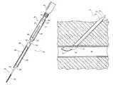
- FIGS. 1 and 2show a conventional vascular closure device that utilizes a balloon to close a hole in a blood vessel.
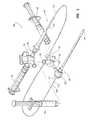
- FIG. 3is an exploded assembly view of one embodiment of an introducer sheath and an associated vascular closure device.
- FIG. 4is a perspective view of the vascular closure device inserted into the introducer sheath.
- FIG. 5is a sectional side elevation view of one embodiment of a patient with the introducer sheath of FIG. 3 positioned within an arteriotomy and the associated vascular closure device extending through the introducer sheath and into a blood vessel.
- FIG. 6is a sectional side elevation view of the patient, introducer sheath, and vascular closure device of FIG. 5 where an expandable portion of the vascular closure device is in an expanded configuration and in contact with the inner wall of the arteriotomy.
- FIG. 7is a sectional side elevation view of another embodiment of the patient, introducer sheath, and vascular closure device of FIG. 6 shown with the introducer sheath connected to a suction apparatus.
- FIG. 8is a sectional side elevation view of another embodiment of the patient, introducer sheath, and the vascular closure device of FIG. 7 shown with the introducer sheath coupled to a sealant source.
- FIG. 9is a sectional side elevation view of another embodiment of the patient, introducer sheath, and the vascular closure device of FIG. 8 with the expandable portion being contracted and being withdrawn through the sealant.
- FIG. 10is a sectional side elevation view of the patient following retraction of the introducer sheath and vascular closure device from the situs of the hole in the blood vessel.
- FIG. 11is a perspective view of one embodiment of a distal end of a main body of the vascular closure device.
- FIG. 12is a perspective view of another embodiment of a distal end of a main body of the vascular closure device where the expandable portion has a tail when the expandable portion is in an expanded configuration.
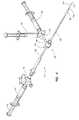
- FIG. 13shows a side view of another embodiment of a vascular closure device.
- FIG. 14shows the vascular closure device from FIG. 13 inserted into a blood vessel.
- FIG. 15shows the vascular closure device from FIG. 13 inserted into the blood vessel with a expandable portion in an expanded configuration and spaced apart from the interior wall of the blood vessel.
- FIG. 16shows the vascular closure device from FIG. 13 with the expandable portion positioned up against the interior wall of the blood vessel.
- FIG. 17shows the vascular closure device from FIG. 13 with the carrier tube and insertion sheath retracted to expose the sealing material to the tissue tract.
- the sealing materialis beginning to change phase and fill in the tissue tract.
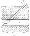
- FIG. 18shows the sealing material as it changes from a liquid/gel to a cubic phase.
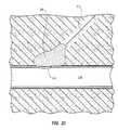
- FIG. 19shows the sealing material deployed adjacent to the hole in the blood vessel after the vascular closure device from FIG. 13 has been removed.
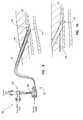
- FIGS. 20-23show another embodiment of the vascular closure device that uses a perforated tube to inject the scaling material into the tissue tract.
- vascular closure devicesA number of embodiments of vascular closure devices are described herein that may be used to close a hole in a blood vessel. It should be appreciated that although the vascular closure devices may be used to close any hole in any animal, the following discussion focuses on vascular closure devices that are used to close a hole in a blood vessel such as an arteriotomy. It should be appreciated, however, that the principles, concepts, and features described herein may apply to numerous other settings and may be used in connection with other uses beyond closing vascular holes (e.g., urinary tract, digestive tract, and the like). Also, it should be appreciated, that the features, advantages, characteristics, etc. of one embodiment may be applied to any other embodiment to form an additional embodiment unless noted otherwise.
- vascular closure devices described hereinmay be used to seal the hole in the blood vessel or arteriotomy following completion of the medical procedure.
- the punctureextends through the patients skin and into the vessel at an oblique angle (e.g., approximately 20° to 45°) relative to the vessel. This makes it possible to insert a device such as a catheter into the vessel without bending the catheter significantly or damaging the blood vessel.
- an introducer sheathextends through the tissue tract and into the blood vessel.
- the introducer sheathallows the medical personnel to quickly and easily insert different medical devices into the vessel without continually reinserting each device through the skin, underlying tissue, and the vessel.
- the introducermay be configured to have a blood flow indicator that provides a visual way for medical personnel to readily determine when the introducer has entered the blood vessel. It should be appreciated, however, that a separate device may be used to locate the blood vessel before the introducer sheath is put into position.
- the sealing materialis injected or forced into the tissue tract area near the hole in the blood vessel.
- the sealing materialmay be configured to melt and flow into the tissue tract.
- Numerous other embodiments of vascular closure devicescan be used that have an expandable portion that can be used to deploy sealing material adjacent to the hole in the blood vessel.
- a vascular closure device 100(alternatively referred to herein as a vascular closure device, vascular puncture closure device, tissue puncture closure device, or internal tissue puncture sealing apparatus) is shown.
- the vascular closure device 100includes an elongated main body or conduit 102 , a fluid dispenser 116 , and a valve assembly 118 .
- the main body or balloon catheter 102has a distal or first end 106 and a proximate or second end 108 .
- the proximate end 108is coupled to the valve assembly 118 , which is in turn coupled to the fluid dispenser 116 .
- a distal tip 112is provided on the distal end 106 of the main body 102 .
- An expandable portion 114(alternatively referred to herein as a balloon or inflatable portion) is also positioned at the distal end 106 of the main body 102 .
- the term “coupled”means the joining of two members directly or indirectly to one another. Such joining may be stationary in nature or movable in nature. Such joining may be achieved with the two members or the two members and any additional intermediate members being integrally formed as a single unitary body with one another or with the two members or the two members and any additional intermediate member being attached to one another. Such joining may be permanent in nature or alternatively may be removable or releasable in nature.
- the configuration of the vascular closure device 100may be altered in any of a number of ways such as by adding additional components, removing components, or rearranging components.
- the valve assembly 118may be integrated into the fluid dispenser 116 so that the resulting device appears to be a single component, but functions as both a fluid dispenser and a valve.
- the valve assembly 118may be eliminated entirely. Numerous other changes may also be made to the vascular closure device 100 .
- the expandable portion 114may be selectively expanded and/or contracted using the fluid from the fluid dispenser 116 .
- the main body 102may include a lumen or passage 104 that extends from the proximate end 108 of the main body 102 to the expandable portion 114 .
- the lumen 104is also in fluid communication with the valve assembly 118 and the fluid dispenser 116 .
- the main body 102may form a conduit that is capable of delivering a fluid from the fluid dispenser 116 to the expandable portion 114 .
- the fluidmay be selectively injected into or suctioned out of the expandable portion 114 to move the expandable portion 114 between an expanded configuration and a contracted configuration.
- the expandable portion 114may be selectively inflated and/or deflated with fluid from the fluid dispenser 116 .
- the valve assembly 118is positioned between the fluid dispenser 116 and the lumen 104 in the main body 102 .
- the valve assembly 118can be used to selectively isolate the lumen 104 from the fluid dispenser 116 . Accordingly, when the valve assembly 118 is open, the fluid dispenser 116 may be used to expand or inflate the expandable portion 114 . Following expansion, the valve assembly 118 may be closed to prevent fluid from flowing back into the fluid dispenser 116 and thus maintain the expandable portion 114 in the expanded configuration.
- valve assembly 118may be omitted and the fluid dispenser 116 may be configured to provide the necessary force (e.g., friction of parts in the fluid dispenser 116 , mechanical lock to hold fluid dispenser 116 in place, and so forth) to prevent the fluid from flowing back from the expandable portion 114 when the fluid dispenser 116 is not being used.
- necessary forcee.g., friction of parts in the fluid dispenser 116 , mechanical lock to hold fluid dispenser 116 in place, and so forth
- the fluid dispenser 116may have any suitable configuration.
- the fluid dispenser 116may include a syringe that is capable of injecting fluid through the lumen 104 and to the expanding portion 114 .
- Other suitable devices or systemsmay also be used as the fluid dispenser 116 .
- the fluid dispenser 116may be used to dispense any type of suitable fluid.
- the fluid provided by the fluid dispenser 116may include standard saline solution or any other suitable liquid.
- the fluidmay include a gas such as carbon dioxide or air. Any fluid that is suitable for medical applications may be used to expand and contract the expandable portion 114 of the vascular closure device 110 .
- the main body 102may have any suitable configuration and may be made of any suitable material.
- the lumen 104may be formed by a tube such as hypotube.
- the hypotubemay include one or more shape memory alloys such as nickel-titanium alloys and the like. In other embodiments, the hypotube may include other materials such as stainless steel and the like.
- the main body 102may also include a guidewire that extends distally from the expandable portion 114 .
- the main body 102may also include multiple lumens to deliver a number of fluids to the distal end 106 .
- the expandable portion 114may be formed from any suitable expandable material.
- the expandable portion 114includes a resilient expandable portion. Suitable examples of such materials include polyurethanes and/or silicones.
- the expandable material used to provide the expandable portion 114may be attached to the main body 102 using any suitable fastening technique or device. For example, the expandable material may be adhered or glued to the main body 102 so that the lumen 104 is in fluid communication with the interior of the expandable portion 114 . Any suitable adhesive may be used for this purpose. Examples of particularly suitable adhesives include cyanoacrylate adhesives (cured with or without a light), acrylic adhesives (cured with or without a light), epoxy adhesives, and the like.
- the expandable materialmay include a urethane balloon available from Advanced Polymers, Salem N.H., as part number 050000030A adhered to nickel-titanium hypotube that is included as part of the main body 102 using any of the following adhesives available from Henkel Corp., Rocky Hill, Conn., as LOCTITE brands 3911 (item number 36536), 3921 (item number 36484), 4011 (item number 18680), or 4061 (item number 18686).
- a primermay be applied before the adhesive.
- a suitable primermay also be obtained from Henkel Corp. as LOCTITE brand 770 (item number 18396).
- the surface of the hypotubemay be etched or roughened in the areas where the adhesive is applied.
- the main body 102 and the expandable portion 114may have any of a number of suitable configurations.
- the expandable portion 114may be integrally formed as part of the main body 102 .
- the expandable portion 114may be injection molded with the remainder of the main body 102 . Numerous other embodiments may also be used to provide the main body 102 and the expandable portion 114 .
- FIGS. 11 and 12various embodiments of the main body 102 are shown with the expandable portion 114 in the expanded configuration.
- the expandable portion 114is positioned at an oblique angle (e.g., about 20° to 40°) relative to the main body 102 .
- the expandable portion 114typically has a shape that is not perfectly round.
- the expandable portion 114can have a shape that is spheroidal, ellipsoidal, or the like.
- the expandable portion 114as being positioned at an oblique angle relative to the main body 102 , is meant to confer the general idea that the side 115 of the expandable portion 114 that is intended to contact the inner surface of the vessel is positioned at an oblique angle prior to or without contacting the inner surface of the vessel (e.g., when the expandable portion 114 is in a rest state).
- the angle between the expandable portion 114 and the main body 102is determined by measuring the angle between the general longitudinal axis 107 of the main body 102 and the side 115 of the expandable portion 114 that is intended to contact the inner surface of the vessel at the location where the axis 107 and the side 115 are the closest to each other ( FIG. 11 ).
- the expandable portion 114may be oriented at an angle of approximately 15° to 55° relative to the main body 102 , approximately 20° to 45° relative to the main body 102 , or, desirably, approximately 25° to 40° relative to the main body 102 .
- the expandable portion 114may be positioned so that the distal tip 112 of the main body 102 extends past the expandable portion 114 .
- the distal tip 112may be atraumatic to facilitate insertion of the distal end 106 into a blood vessel without damaging or harming the blood vessel.
- the distal tip 112may be formed by a guidewire that is coupled to the expandable portion 114 and/or the main body 102 .
- the guidewiremay be surrounded by a spring to make it atraumatic.
- FIG. 11shows another embodiment of the vascular closure device 100 where the expandable portion 114 is positioned on the distal tip 112 of the main body 102 such that the main body 102 terminates at the expandable portion 114 .
- This embodimentmay be advantageous because only the deflated expandable portion 114 needs to be withdrawn through the hole after the access hole is sealed.
- the vascular closure device 100also includes an introducer assembly or sheath 120 .
- the introducer sheath 120includes a valve 130 positioned at a proximal end 126 and an elongated tube or conduit 122 that extends from the valve 130 to a distal end 124 .
- the tube 122has a lumen 142 ( FIG. 5 ) that is receptive of the main body 102 .
- the introducer sheath 120also includes at least one opening or side-port 128 positioned at the proximal end 126 that is in fluid communication with the lumen 142 .
- the valve 130branches to a suction port 132 and a sealing material port 134 . It should be appreciated that in other embodiments the suction port 132 and sealing material port 134 may be one and the same so that the valve 130 does not branch.
- the suction port 132is in fluid communication with a suction source 136 or other evacuator such as, for example, a syringe.
- the sealing material port 134is in fluid communication with a supply of sealing material, such as a syringe 138 that contains the sealing material.
- the valve 130may comprise a translucent three-way valve that moves between a first or closed position where the suction port 132 and the sealing material port 134 are both isolated from the lumen 142 , a second position where the suction port 132 is in fluid communication with the lumen 142 , and a third position where the sealing material port 134 is in fluid communication with the lumen 142 . Details of the valve 130 and the associated suction port 132 and sealing material port 134 are shown in FIGS. 5-9 .
- the main body 102may be inserted into the lumen 142 of the introducer sheath 120 as shown.
- the main body 102is sized so that it does not fill the entire lumen 142 .
- the side-port 128is in fluid communication with the portion of the lumen 142 that is not filled.
- a stopper sleeve or spacer 140is shown disposed over the main body 102 to limit the insertion distance of the main body 102 into the introducer sheath 120 .
- the length of the spacer 140is chosen so that the distal end 106 of the main body 102 extends beyond the distal end 124 of the introducer sheath 120 by a predetermined distance.
- the predetermined distanceis approximately 2.5 cm to 4.0 cm. The distance is chosen to allow the expandable portion 114 of the main body 102 to pass through the introducer sheath 120 and into a blood vessel as discussed in more detail below.
- the spacer 140may comprise a split tube of metal or plastic that can be easily removed as desired.
- the vascular closure device 100is shown with the introducer sheath 120 inserted through a hole 144 in a blood vessel 148 .
- the introducer sheath 120may be used for introducing instruments during the medical procedure as well as to close the hole 144 .
- another introducermay be used during the procedure.
- the introducermay be swapped for the introducer sheath 120 .
- the main body 102may be inserted through the lumen 142 until the expandable portion 114 extends beyond the tip of the distal end 124 of the introducer sheath 120 and into the blood vessel 148 .
- the introducer sheath 120 and main body 102are oriented at an oblique angle relative to the walls of the blood vessel 148 .
- the main body 102 and expandable portion 114when positioned in the lumen 142 , may restrict passage of other devices or objects through the lumen 142 .
- the expandable portion 114may be expanded by opening the valve 118 and depressing the fluid dispenser 116 .
- FIG. 5shows the expandable portion 114 after it has been expanded in the blood vessel 148 .
- the expandable portion 114is positioned at an oblique angle relative to the main body 102 .
- the valve 118may be closed to maintain the expandable portion 114 in an expanded position.
- the main body 102 and the introducer sheath 120are retracted until the expandable portion 114 contacts an inner wall 150 of the blood vessel 148 and seals the internal side of the hole 144 as shown in FIG. 6 .
- the expandable portion 114is positioned so that it is parallel to the inner wall 150 as it moves toward and contacts the inner wall 150 .
- the expandable portion 114forms a good seal over the hole 144 and provides sufficient tactile feedback to allow the medical professional to determine when the expandable portion 114 is in position.
- the vascular closure device 100may include a marking or some other indicia to allow the medical personnel to determine the rotational orientation of the main body 102 . In this way, the medical personnel can reorient the main body 102 and the expandable portion 114 so that it is parallel to the inner wall 150 before moving the expandable portion 114 into contact with the inner wall 150 .
- the side-port valve 130is opened to allow fluid communication between the unfilled space of the lumen 142 and the suction source 136 as shown in FIG. 7 .
- the pressureis lowered in the lumen 142 by withdrawing a stem 152 of the suction source 136 (in this embodiment, a syringe) or by some other suction device.
- a situs 154 of the hole 144is aspirated, removing fluids from the tissue tract 146 via the lumen 142 .
- a surgeon or other medical professionalmay visually inspect the fluid contents evacuated through the translucent valve 130 to assess blood flow through the hole 144 . This allows the medical professional to ensure that the introducer sheath 120 and/or the expandable portion 114 are properly positioned within the blood vessel 148 . A flow of blood may indicate that the expandable portion 114 is not properly sealing the hole 144 .
- the valve 130is toggled to create a fluid communication path between the lumen 142 and the sealing material contained in the syringe 138 or other sealing material supply as shown in FIG. 8 .
- the syringe 138holds a volume of sealing material that is injected into the introducer sheath 120 via the side-port 128 as a stem 156 is depressed.
- the sealantflows through the lumen 142 and into the tissue tract 146 . Further, because the tissue tract 146 has been evacuated and is in a vacuum condition, the sealing material is drawn through the annulus toward the hole 144 .
- the vacuum condition of the situs 154 external to the hole 144causes the sealing material to quickly and efficiently fill all of the voids around the hole 144 and in the tissue tract 146 .
- the syringe 138holds a volume of sealing material sufficient to fill the lumen 142 and therefore the tissue tract 146 .
- the introducer sheath 120is preferably withdrawn with respect to the expandable portion 114 to allow the sealing material to fill the tissue tract 146 . Therefore, in order to facilitate retraction of the introducer sheath 120 , the spacer 140 ( FIG. 4 ) is removed.
- the sealing materialincludes a liquid or gel sealant that includes any of the following thrombin, collagen, fibrin/fibrinogen, cyanoacrylate, polyvinyl alcohol, polyethylene glycol, chitosan, poly-n-acetyl glucosamine, and combinations thereof (e.g., thrombin and collagen, fibrin/fibrinogen and collagen, cyanoacrylate and collagen, or thrombin and fibrin/fibrinogen).
- the sealing materialmay include implants (implant is positioned adjacent to the exterior of the hole 146 using a variety of different techniques).
- Implantsare typically provided as a solid, fiber, compressible foam, or the like while sealants are provided as a liquid, gel, or the like.
- the sealing materialmay operate by mechanically blocking the hole in the vessel, reacting with the blood or other nearby tissue to block the hole, or the like. In some embodiments, the sealing material may not be dependent on a biochemical reaction with blood or other bodily fluids to create a hemostatic seal.
- the gels or foams used according to some aspects of the present inventionmay in some cases be activated or cured by, for example, application of a second fluid, UV light, or other activation mechanisms.
- the expandable portion 114is contracted as shown in FIG. 9 by reopening the valve 118 ( FIG. 4 ).
- the stem 158 ( FIG. 4 ) of the fluid dispenser 116 ( FIG. 4 )may be retracted to ensure fill contraction of the expandable portion 114 .
- the main body 102 and the introduction sheath 120are retracted, with the expandable portion 114 sliding through the sealing material.
- manual pressuremay be applied to the arteriotomy site to counteract any sealing action disruption caused by the act of pulling the expandable portion 114 through the sealing material.
- manual pressureis applied for only a fraction of the time allocated to traditional arteriotomy closures.
- manual pressuremay be applied following retraction of the vascular closure device 100 for only ten minutes or less.
- the sealing materialremains in the tissue tract 146 sealing the arteriotomy 144 as shown in FIG. 10 .
- the vascular closure device 250may be used to deploy sealing material adjacent to and outside of the hole in the blood vessel.
- the sealing materialfunctions to block the hole in the blood vessel and/or the tissue tract to stop the bleeding.
- the sealing materialmay be a lipid based sealing material.
- the sealing materialmay include monoglycerides of saturated and unsaturated fatty acids.
- the sealing materialmay include one or more of such monoglycerides alone or in combination with other materials such as therapeutic agents, additives, and carrier materials.
- the therapeutic agentsmay include drugs or other substances that provide local or systemic therapeutic effect in the body. Additives may be included to alter the physical properties such as the melting point, strength, resiliency, etc. of the sealing material.
- the sealing materialmay comprise a monoglyceride including a fatty acid group having 12 to 22 carbon atoms.
- the sealing materialmay include glycerol monooleate, glycerol monostearate, glycerol monopalmitate, glycerol monolaurate, glycerol monocaproate, glycerol monocaprylate, glycerol monolinoleate, glycerol monolinolenate, glycerol monomyristate, and/or glycerol monoarachidonate.
- Those materials that may be preferable for use as the sealing materialinclude glycerol, monooleate, glycerol monolinoleate, and/or glycerol monolinolenate, in any combination or amount.
- the sealing materialmay melt, gel, or otherwise undergo a phase change when deployed adjacent to the hole in the blood vessel.
- the sealing materialAfter the sealing material has been inserted into the tissue tract, it is heated by the patient's body until it begins to melt or gel.
- the sealing materialmay have a melting point that is no more than 37° C.
- the sealing materialmay have a melting point that is about 27° C. to 37° C., about 30° C. to 37° C., or about 34° C. to 37° C.
- the sealing materialmay flow into the tissue tract toward the hole in the blood vessel.
- the sealing materialmay begin to expand and form a cubic phase due to exposure to bodily fluids.
- the sealing materialmay expand up to 46% of its original size.
- the sealing materialmay also exhibit adhesive properties that help to hold the sealing material in place in the tissue tract.
- the expansion of the sealing material and formation of the cubic phase(the sealing material becomes solid or non-flowable in the cubic phase) may act to hold the sealing material in place over the hole in the blood vessel thereby closing the hole in the blood vessel. It should be appreciated that any of the foregoing sealing materials may also be used with the vascular closure device 110 .
- the vascular closure devices 250facilitates deployment of the sealing material in the tissue tract of the patient.
- the sealing materialblocks the tissue tract and stops the bleeding.
- the sealing materialis bio-absorbable to allow it to be removed by the body's natural processes.
- the sealing materialmay be deployed with and coupled to another bio-absorbable component such as a sealing plug (e.g., collagen plug) or anchor both of which may also be bio-absorbable (e.g., PLA and PGA materials).
- the vascular closure device 250may be configured to not leave any components inside the blood vessel after the closure procedure is over (i.e., an extra-vascular closure device). In this embodiment, the sealing material and any other components left in the patient are outside of the blood vessel.
- the vascular closure device 250may be used to close and/or seal a hole or puncture in a blood vessel such as an arteriotomy.
- the vascular closure device 250has a distal end 264 and a proximal end 265 and includes a handle 251 , a carrier tube or carrier member 252 (which may be referred to as an introducer sheath in some embodiments), sealing material 256 , a stopper 254 , and a vessel locator assembly or vessel locator portion 260 .
- the vessel locator assembly 260includes a central tube 259 that extends through the handle 251 , the carrier tube 252 , the stopper 254 , and the sealing material 256 .
- the vessel locator assembly 260also includes an expandable portion 266 positioned at the distal end 264 of the vascular closure device 250 and a syringe 275 positioned at the proximal end 265 of the vascular closure device 250 .
- the syringe 275is coupled to and in fluid communication with the central tube 259 .
- the handle 251is positioned at the proximal end 265 of the vascular closure device 250 and allows the user to manipulate the various components of the device 250 to facilitate closing the hole in the blood vessel.
- the handle 251includes a first tube 261 having a distal end that is sized to slidably receive the carrier tube 252 and a proximal end that is sized to slidably receive a syringe 275 .
- the first tube 261includes a slot 267 that receives an actuation member, protrusion, or pin 263 that extends outward from the carrier tube 252 .
- the usercan reciprocally move the actuation member 263 proximally and distally in the slot 267 to retract and extend, respectively, the carrier tube 252 . Retracting the carrier tube 252 when the vascular closure device 250 is deployed exposes the sealing material 256 to the tissue tract.
- the syringe 275may be used to selectively expand and/or contract the expandable portion 266 .
- Any suitable fluidmay be used to expand the expandable portion 266 .
- fluidssuch as saline solution, carbon dioxide, or air may be suitable.
- a guide wire and a spring 268may be coupled proximally to the expandable portion 266 .
- the guide wire and the spring 268are configured to be atraumatic to prevent the distal end 264 of the vascular closure device 250 from puncturing or damaging the blood vessel.
- the vascular closure device 250is configured so that when it is inserted into the tissue tract, the expandable portion 266 is positioned inside the blood vessel.
- the expandable portion 266may be configured to move between the contracted configuration shown in FIG. 13 and the expanded configuration shown in FIG. 15 . This allows the expandable portion 266 to be inserted into the blood vessel, expanded, and then moved into contact with the interior wall of the blood vessel adjacent to the hole.
- the expandable portion 266 and the sealing material 256are spaced apart a predetermined distance so that when the expandable portion 266 is positioned against the interior wall of the blood vessel, the sealing material 256 is positioned just outside of the hole in the blood vessel. In the embodiment shown in FIGS.
- the expandable portion 266includes a balloon that may use the same materials and/or otherwise be similar to the balloon described in connection with the expandable portion 114 .
- the expandable portion 266may be positioned at an oblique angle like the expandable portion 114 .
- the central tube 259 and any of the other components of the vessel locator assembly 260may be made of any suitable material such as metal, plastics, or composites. Since the vascular closure device 250 is a medical device, the materials used may also be medical grade (medical grade metals, plastics, or composites). In one embodiment, the central tube 259 may be made of metals such as stainless steel or memory shape metals such as nitinol, and the like.
- the stopper 254is provided to prevent the sealing material 256 from moving proximally as the carrier tube 252 moves proximally. Accordingly, the stopper 254 is positioned just proximal to the sealing material 256 inside the carrier tube 252 and the stopper 254 is coupled to the central tube 259 so that it is fixed in position.
- the vascular closure device 250may be configured to indicate when the expandable portion 266 is in contact with the interior wall of the blood vessel.
- One problem associated with locating the wall of the blood vesselis that the user may be unable to feel when the expandable portion 266 has contacted the wall of the blood vessel. The user may continue to pull on the vascular closure device 250 causing it to distort and bend until it passes through the hole in the blood vessel or the expanded expandable portion 266 may tear through the hole in the wall of the blood vessel causing additional injury to the patient.
- the first tube 261 and the syringe 275are coupled together in a manner that signals to the user when the expanded expandable portion 266 is positioned against the interior wall of the blood vessel.
- the syringe 275is positioned to move lengthwise in the first tube 261 .
- the central tube 259is coupled to the syringe 275 so that when the expandable portion 266 contacts the interior wall of the blood vessel, the tension on the central tube 259 pulls the syringe 275 further into the first tube 261 .
- a spring 271is positioned between the first tube 261 and the syringe 275 to bias the syringe 275 in the proximal direction and resistant the tension exerted by the core wire 270 .
- the spring 271is configured to provide just the right amount of force so that the spring 271 is only compressed, and consequently the syringe 275 moved, when the expandable portion 266 has contacted the interior wall of the blood vessel.
- An indicator pin 298extends outward from the syringe 275 and travels in a slot 273 in the first tube 261 . As the spring 271 is compressed, the indicator pin 298 moves distally in the slot 273 . In operation, the user can pull back on the vascular closure device 250 while watching the indicator pin 298 . When the indicator pin 298 begins to move distally in the slot 273 , the user knows that the expandable portion 266 is positioned against the interior wall of the blood vessel. The indicator pin 298 also prevents the spring 271 from biasing the syringe 275 out the proximal end of the first tube 261 .
- the vascular closure device 250may be configured to emit a beep to alert the user that the expandable portion 266 is positioned against the interior wall of the blood vessel.
- FIGS. 20-23show another embodiment of the vascular closure device 250 .
- the vascular closure device 250includes a perforated tube 292 that is used to dispense the sealing material 256 into the tissue tract.
- the vascular closure device 250may be provided with another syringe coupled to the proximal end of the perforated tube 292 .
- the syringemay be used to inject the sealing material 256 out through the holes 293 in the perforated tube 292 .
- the distal end of the perforated tube 292may be blocked or closed so that the sealing material 256 is forced out the sides of the perforated tube 292 against the walls of the tissue tract instead of down against the hole, which may result in sealing material entering the blood stream.
- the holes 293 in the perforated tube 292may be sized to regulate the flow of the sealing material 256 .
- the holes 293may get larger moving in a distal direction along the perforated tube 292 so that the largest holes 293 are positioned nearest the distal end of the perforated tube 292 .
- This configurationresults in an even amount of sealing material 256 being dispensed along the perforated tube 292 .
- the holes 293may be configured to be the same size or all of the holes 293 may be unique sizes. Numerous configurations are possible.
- the initial stepmay be to exchange the procedural access sheath for the introducer sheath 262 .
- Thisis done by placing a guidewire through the procedural sheath and into the blood vessel 308 .
- the procedural sheathis then withdrawn from the body while holding digital pressure on the blood vessel 308 , upstream from the sheath, and while holding the guidewire in place.
- a closure dilatoris placed within the introducer sheath 262 and the distal tapered end of the closure dilator is back-loaded onto the guidewire.
- the closure dilator and the introducer sheath 262are advanced together distally over the guidewire, through the tissue tract 312 , and into the blood vessel 308 .
- the introducer sheath 262includes a distal side hole (not shown) near the distal end of the introducer sheath 262 .
- the closure dilatoralso includes a distal side hole that is configured to align with the distal side hole in the introducer sheath 262 when the closure dilator is positioned in the introducer sheath 262 .
- the closure dilatoralso has a proximal side hole at the proximal end of the closure dilator that is in fluid communication with the distal side hole of the closure dilator and the closure sheath.
- the distal and proximal side holesmay be fluidly connected by way of a dedicated lumen or bore.
- the distal and proximal side holesmay be fluidly connected by the central lumen of the closure dilator that the guidewire is positioned in.
- the distal and proximal side holes in the introducer sheath 262 and the closure dilatorare provided to allow blood to flash back when the introducer sheath 262 is correctly positioned in the blood vessel 308 .
- the userpulls the introducer sheath 262 in a proximal direction until the blood flow just stops.
- the introducer sheath 262is now placed in the correct position to continue the procedure.
- the next stepis to withdraw the closure dilator and the guidewire while holding the introducer sheath 262 in place.
- the introducer sheath 262is sized to slidably receive the vascular closure device 250 therein.
- the distal ends of the introducer sheath 262 and the carrier tube 252have a tapered shape so that the tip will align with the lengthwise axis of the blood vessel 308 when the introducer sheath 262 is inserted through the tissue tract 312 at an angle of about 20-45 degrees to the vessel axis.
- the vascular closure device 250is introduced into the proximal end of the introducer sheath 262 .
- the vascular closure device 250may be configured to advance until it snaps, locks, or otherwise mates together with the carrier tube 62 . In this position, the distal end 264 of the vascular closure device 250 extends out of the distal end of the introducer sheath 262 and into the blood vessel 308 . It should be noted that the vascular closure device 250 and the introducer sheath 262 may be configured so that when they are coupled together, the distal end 264 extends into the blood vessel 308 a predetermined amount,
- FIG. 14shows the expandable portion 266 in position in the blood vessel 308 .
- the expandable portion 266is expanded using the syringe 275 .
- FIG. 15shows the expandable portion 266 in the expanded configuration.
- the introducer sheath 262 and the vascular closure device 250are drawn away from the patient until the expandable portion 266 contacts the vessel wall at the puncture site as shown in FIG. 16 .
- the introducer sheath 262 and the carrier tube 252are withdrawn to expose the sealing material 256 to the tissue tract 312 .
- the sealing materialbegins to melt as it is heated by the body and flows down toward the hole 310 in the blood vessel 308 as shown in FIG. 17 .
- the expandable portion 266blocks the hole 310 so that the sealing material 256 does not flow into the bloodstream.
- the sealing material 256begins to form a cubic phase upon exposure to bodily fluids such as blood and the like. This causes the sealing material 256 to expand and fill the tissue tract 312 adjacent to the hole 310 in the blood vessel 308 as shown in FIG. 18 .
- the vascular closure device 250may be configured to use a second non-flowable sealing material or anchor along with the sealing material 256 .
- the vascular closure device 250may be configured to deposit a small collagen plug adjacent to the hole 310 to prevent the sealing material 256 from entering the blood vessel 308 .
- the next stepis to contract the expandable portion 266 and withdraw the vessel locator assembly 260 and the remainder of the vascular closure device 250 from the tissue tract 312 .
- the sealing material 256swells or otherwise moves to fill the gap where the vessel locator assembly 260 used to be.
- the hole in the blood vessel 308is now sealed by clotting action and the sealing material 256 positioned in the tissue tract 312 .
- the method of using the vascular closure device 250 shown in FIGS. 20-23is similar to the method of using the vascular closure device 250 shown in FIGS. 14-19 .
- the userinstead of passively allowing the sealing material 256 to melt and fill the tissue tract 312 , the user can inject any desired amount of sealing material 256 into the tissue tract 312 through the perforated tube 292 . This allows for additional sealing material 256 to be deployed. Also, the user may inject sealing material 256 through the perforated tube 292 as the perforated tube 292 is being withdrawn so that the sealing material fills up the entire tissue tract 312 .
- a method of closing a hole in a vessel of a patientcomprises: moving an expandable portion of a vascular closure device through the hole and into the vessel, the vascular closure device including a main body that extends through the hole at an oblique angle relative to the vessel; expanding the expandable portion of the vascular closure device; and moving the expandable portion into contact with an inner wall of the vessel to block the hole, the expandable portion being oriented at least substantially parallel to the inner wall of the vessel shortly before contacting the inner wall.
- the methodmay comprise applying a sealing material to the hole while the expandable portion is in contact with the inner wall of the vessel.
- the sealing materialmay include a sealant.
- the sealantmay be applied using suction.
- the methodmay comprise applying a sealing material to the hole while the expandable portion is in contact with the inner wall of the vessel; contracting the expandable portion; and removing the expandable portion of the vascular closure device from the vessel.
- the methodmay comprise applying manual pressure to the hole after removing the expandable portion of the vascular closure device from the vessel.
- the vesselmay include a blood vessel.
- the expandable portionmay be oriented at an oblique angle relative to the main body shortly before contacting the inner wall.
- the expandable portionmay be made, at least in part, of polyurethane.
- a method of closing a hole in a vessel of a patientcomprises: expanding an expandable portion of a vascular closure device inside the vessel, the expandable portion being oriented at an oblique angle relative to a main shaft of the vascular closure device; and moving the expandable portion into contact with an inner wall of the vessel to block the hole.
- the methodmay comprise applying a sealing material to the hole while the expandable portion is in contact with the inner wall of the vessel.
- the sealing materialmay include a sealant.
- the sealantmay be applied using suction.
- the methodmay comprise applying a sealing material to the hole while the expandable portion is in contact with the inner wall of the vessel; contracting the expandable portion; and removing the expandable portion of the vascular closure device from the vessel.
- the methodmay comprise applying manual pressure to the hole after removing the expandable portion of the vascular closure device from the vessel.
- the vesselmay include a blood vessel such as an artery.
- the expandable portionmay be made, at least in part, of polyurethane.
- the expandable portionmay include a tail.
- the methodmay comprise moving the expandable portion of the vascular closure device through an introducer that extends into the vessel.
- a method of closing a hole in a blood vessel of a patientcomprises: expanding an expandable portion of a vascular closure device inside the blood vessel, the expandable portion being oriented at an oblique angle relative to a main shaft of the vascular closure device; moving the expandable portion into contact with an inner wall of the vessel to block the hole; applying a sealing material to the hole while the expandable portion is in contact with the inner wall of the blood vessel; contracting the expandable portion; and removing the expandable portion of the vascular closure device from the blood vessel.
- the sealing materialmay include a sealant.
- the expandable portionmay include a tail.
- a vascular closure devicecomprises: a main body having a distal end; and an expandable portion positioned at the distal end of the main body, the expandable portion being configured to be inserted into a hole in a vessel of a patient; wherein the expandable portion is oriented at an oblique angle relative to the main body when the expandable portion is in an expanded configuration.
- the main bodymay form a conduit that is in fluid communication with the expandable portion, the expandable portion being selectively expandable with fluid delivered by the conduit.
- the main bodymay include hypotube that forms the conduit.
- the main bodymay include a guidewire.
- the expandable portionmay be attached to the guidewire.
- the guidewiremay include hypotube to deliver fluid to the expandable portion.
- the vascular closure devicemay comprise a conduit to deliver sealant to an area adjacent to the expandable portion.
- the expandable portionmay be positioned adjacent to a distal tip of the main body.
- the expandable portionmay extend outward from a distal tip of the main body.
- the expandable portionmay be oriented at an angle of approximately 20° to 70° relative to the main body when the expandable portion is in the expanded configuration.
- the expandable portionmay be made, at least in part, of polyurethane.
- the expandable portionmay include a tail.
- a vascular closure devicecomprises: a guidewire; and an expandable portion attached to the guidewire; wherein the expandable portion is configured to be inserted into a vessel of a patient through a hole in a wall of the vessel, the vascular closure device being configured to close the hole in the wall of the vessel.
- a vascular closure devicecomprises: a cylindrical tube; and an expandable portion attached to the cylindrical tube; wherein the expandable portion is configured to be inserted into a vessel of a patient through a hole in a wall of the vessel, the vascular closure device being configured to close the hole in the wall of the vessel.
- a vascular closure devicecomprises an expandable portion made at least in part of polyurethane, the expandable portion being configured to be inserted into a vessel of a patient through a hole in a wall of the vessel, the vascular closure device being configured to close the hole in the wall of the vessel.
- an internal tissue puncture sealing apparatuscomprises a first thin, elongated conduit having a first central lumen and first and second ends.
- the first endmay be insertable through the internal tissue puncture and has an inflation segment in fluid communication with the central lumen.
- the first endmay include an expandable member that is selectively inflatable with a fluid via the central lumen.
- the apparatusmay also include a second thin, elongated conduit having a second central lumen receptive of the first thin, elongated conduit.
- the proximal end of the second conduithas at least one valved side-port in fluid communication with a space between the first and second conduits.
- the valved side-portmay include a vacuum communication path and a sealant injection path, which enable aspiration of a tissue puncture site and sealing of the puncture.
- a method of closing a hole in a vessel wallmay include inserting an inflatable device through an introducer that is disposed in the vessel, inflating the inflatable device, sealing the inflatable device against an inner wall of the vessel, reducing the pressure inside of the introducer, injecting a sealant into the introducer, deflating the inflatable device, and removing the inflatable device through the sealant. Following removal of the inflatable device, manual pressure may be applied to the hole for a short period of time to ensure continued hemostasis.
- a specially designed introducermay be swapped with a standard introducer used to facilitate insertion of vascular tools used to perform a vascular procedure prior to inserting the inflatable device.
- the word “or” when used without a preceding “either”shall be interpreted to be inclusive (e.g., “x or y” means one or both x or y).
- the term “and/or”shall also be interpreted to be inclusive (e.g., “x and/or y” means one or both x or y). In situations where “and/or” or “or” are used as a conjunction for a group of three or more items, the group should be interpreted to include one item alone, all of the items together, or any combination or number of the items.
- terms used in the specification and claimssuch as have, having, include, and including should be construed to be synonymous with the terms comprise and comprising.
- a stated range of 1 to 10should be considered to include and provide support for claims that recite any and all subranges or individual values that are between and/or inclusive of the minimum value of 1 and the maximum value of 10; that is, all subranges beginning with a minimum value of 1 or more and ending with a maximum value of 10 or less (e.g., 5.5 to 10, 2.34 to 3.56, and so forth) or any values from 1 to 10 (e.g., 3, 5.8, 9.9994, and so forth).
Landscapes
- Health & Medical Sciences (AREA)
- Surgery (AREA)
- Life Sciences & Earth Sciences (AREA)
- Biomedical Technology (AREA)
- Nuclear Medicine, Radiotherapy & Molecular Imaging (AREA)
- Engineering & Computer Science (AREA)
- Cardiology (AREA)
- Heart & Thoracic Surgery (AREA)
- Medical Informatics (AREA)
- Molecular Biology (AREA)
- Animal Behavior & Ethology (AREA)
- General Health & Medical Sciences (AREA)
- Public Health (AREA)
- Veterinary Medicine (AREA)
- Surgical Instruments (AREA)
Abstract
Description
Claims (21)
Priority Applications (9)
| Application Number | Priority Date | Filing Date | Title |
|---|---|---|---|
| US11/967,979US9282953B2 (en) | 2007-12-31 | 2007-12-31 | Systems and methods for locating and closing a tissue puncture |
| AU2008347098AAU2008347098B2 (en) | 2007-12-31 | 2008-12-22 | Vascular closure device |
| AT08869449TATE553701T1 (en) | 2007-12-31 | 2008-12-22 | SYSTEM FOR LOCALIZING AND CLOSING A TISSUE PUNCTURE |
| JP2010540654AJP5602023B2 (en) | 2007-12-31 | 2008-12-22 | System and method for detecting and sealing tissue perforations |
| CA2707628ACA2707628C (en) | 2007-12-31 | 2008-12-22 | System for and method of locating and closing a tissue puncture |
| ES08869449TES2387053T3 (en) | 2007-12-31 | 2008-12-22 | System to locate and close a tissue puncture |
| PCT/US2008/013967WO2009088441A1 (en) | 2007-12-31 | 2008-12-22 | System for and method of locating and closing a tissue puncture |
| EP08869449AEP2227148B1 (en) | 2007-12-31 | 2008-12-22 | System for locating and closing a tissue puncture |
| CR11543ACR11543A (en) | 2007-12-31 | 2010-06-29 | SYSTEM AND METHOD FOR LOCATING AND CLOSING A TISSUE PUNCTURE |
Applications Claiming Priority (1)
| Application Number | Priority Date | Filing Date | Title |
|---|---|---|---|
| US11/967,979US9282953B2 (en) | 2007-12-31 | 2007-12-31 | Systems and methods for locating and closing a tissue puncture |
Publications (2)
| Publication Number | Publication Date |
|---|---|
| US20090171281A1 US20090171281A1 (en) | 2009-07-02 |
| US9282953B2true US9282953B2 (en) | 2016-03-15 |
Family
ID=40351982
Family Applications (1)
| Application Number | Title | Priority Date | Filing Date |
|---|---|---|---|
| US11/967,979Expired - Fee RelatedUS9282953B2 (en) | 2007-12-31 | 2007-12-31 | Systems and methods for locating and closing a tissue puncture |
Country Status (9)
| Country | Link |
|---|---|
| US (1) | US9282953B2 (en) |
| EP (1) | EP2227148B1 (en) |
| JP (1) | JP5602023B2 (en) |
| AT (1) | ATE553701T1 (en) |
| AU (1) | AU2008347098B2 (en) |
| CA (1) | CA2707628C (en) |
| CR (1) | CR11543A (en) |
| ES (1) | ES2387053T3 (en) |
| WO (1) | WO2009088441A1 (en) |
Cited By (1)
| Publication number | Priority date | Publication date | Assignee | Title |
|---|---|---|---|---|
| US10849615B2 (en)* | 2016-12-15 | 2020-12-01 | Heartstitch, Inc. | Balloon component for locating a suturing device |
Families Citing this family (28)
| Publication number | Priority date | Publication date | Assignee | Title |
|---|---|---|---|---|
| WO2011025528A1 (en)* | 2009-08-31 | 2011-03-03 | St. Jude Medical Puerto Rico Llc | Compressible arteriotomy locator for vascular closure devices and methods |
| US20210186473A1 (en)* | 2010-06-24 | 2021-06-24 | St. Croix Surgical Systems, Llc | Percutaneous wound barrier |
| WO2012148745A1 (en)* | 2011-04-25 | 2012-11-01 | St. Jude Medical Puerto Rico Llc | Distal balloon bond for temporary sealing location device and methods |
| CN107096111A (en)* | 2011-05-26 | 2017-08-29 | 雅培心血管系统有限公司 | The conduit of thin hypotube is cut with stairstepping |
| US10485524B2 (en) | 2011-10-25 | 2019-11-26 | Essential Medical, Inc. | Instrument and methods for surgically closing percutaneous punctures |
| US9757105B2 (en) | 2012-03-23 | 2017-09-12 | Accessclosure, Inc. | Apparatus and methods for sealing a vascular puncture |
| US9757104B2 (en) | 2012-07-19 | 2017-09-12 | Essential Medical, Inc. | Multi-lumen tamper tube |
| US10639019B2 (en) | 2013-03-15 | 2020-05-05 | Arrow International, Inc. | Vascular closure devices and methods of use |
| US10154835B2 (en) | 2013-05-09 | 2018-12-18 | Essential Medical, Inc. | Vascular closure device with conforming plug member |
| EP3858254B1 (en) | 2013-12-23 | 2024-04-24 | Teleflex Life Sciences LLC | Vascular closure device |
| CN205287203U (en) | 2014-09-04 | 2016-06-08 | 雅培心血管系统有限公司 | balloon catheter |
| CN206355424U (en) | 2014-09-04 | 2017-07-28 | 雅培心血管系统有限公司 | Balloon catheter |
| MA40946A (en)* | 2014-11-14 | 2017-09-19 | Access Closure Inc | APPARATUS AND METHODS FOR MAKING A VASCULAR PUNCTURE WATERTIGHT |
| EP4147649A1 (en)* | 2015-02-10 | 2023-03-15 | Teleflex Life Sciences Limited | Closure device for sealing percutaneous opening in a vessel |
| EP4299019A3 (en) | 2015-04-01 | 2024-03-06 | Boston Scientific Scimed, Inc. | Systems for delivery of gel embolics |
| CN106166323A (en) | 2015-05-19 | 2016-11-30 | 雅培心血管系统有限公司 | Balloon catheter |
| EP3095480B1 (en) | 2015-05-19 | 2021-01-13 | Abbott Cardiovascular Systems, Inc. | Catheter having monolithic multilayer distal outer member |
| US10555727B2 (en) | 2015-06-26 | 2020-02-11 | Essential Medical, Inc. | Vascular closure device with removable guide member |
| TR201701264A2 (en)* | 2017-01-27 | 2018-08-27 | Invamed Saglik Ilac Sanayi Ve Ticaret Anonim Sirketi | ANGIOGRAPHY INTERFERENCE CLOSING SYSTEM |
| KR20240150538A (en)* | 2018-01-29 | 2024-10-15 | 액세스클로저, 아이엔씨. | Apparatus and method for sealing a vascular puncture |
| JPWO2019189759A1 (en)* | 2018-03-30 | 2021-04-08 | 日本ゼオン株式会社 | Hemostasis device and hemostatic kit |
| US11766544B2 (en) | 2020-05-01 | 2023-09-26 | Terumo Medical Corporation | Vascular closure device and related methods |
| US11690607B2 (en)* | 2020-05-01 | 2023-07-04 | Terumo Medical Corporation | Vascular closure device and related methods |
| US12390249B2 (en) | 2020-07-31 | 2025-08-19 | Teleflex Life Sciences Llc | Access sheath with valve assembly |
| US12383246B2 (en) | 2020-10-12 | 2025-08-12 | Abbott Cardiovascular Systems, Inc. | Vessel closure device with improved safety and tract hemostasis |
| US20220287698A1 (en)* | 2021-03-10 | 2022-09-15 | St. Croix Surgical Systems, Llc | Percutaneous wound barrier |
| CN118000809A (en)* | 2022-11-10 | 2024-05-10 | 深圳市先健纬康科技有限公司 | A puncture hole closing device |
| CN120501470B (en)* | 2025-07-21 | 2025-09-12 | 四川省医学科学院·四川省人民医院 | Compression hemostat |
Citations (137)
| Publication number | Priority date | Publication date | Assignee | Title |
|---|---|---|---|---|
| US4317445A (en) | 1980-03-31 | 1982-03-02 | Baxter Travenol Laboratories, Inc. | Catheter insertion unit with separate flashback indication for the cannula |
| US4744364A (en) | 1987-02-17 | 1988-05-17 | Intravascular Surgical Instruments, Inc. | Device for sealing percutaneous puncture in a vessel |
| US4890612A (en) | 1987-02-17 | 1990-01-02 | Kensey Nash Corporation | Device for sealing percutaneous puncture in a vessel |
| US5021059A (en) | 1990-05-07 | 1991-06-04 | Kensey Nash Corporation | Plug device with pulley for sealing punctures in tissue and methods of use |
| US5061274A (en) | 1989-12-04 | 1991-10-29 | Kensey Nash Corporation | Plug device for sealing openings and method of use |
| US5108421A (en)* | 1990-10-01 | 1992-04-28 | Quinton Instrument Company | Insertion assembly and method of inserting a vessel plug into the body of a patient |
| US5192302A (en) | 1989-12-04 | 1993-03-09 | Kensey Nash Corporation | Plug devices for sealing punctures and methods of use |
| US5192300A (en) | 1990-10-01 | 1993-03-09 | Quinton Instrument Company | Insertion assembly and method of inserting a vessel plug into the body of a patient |
| US5222974A (en) | 1991-11-08 | 1993-06-29 | Kensey Nash Corporation | Hemostatic puncture closure system and method of use |
| US5282827A (en) | 1991-11-08 | 1994-02-01 | Kensey Nash Corporation | Hemostatic puncture closure system and method of use |
| US5290310A (en) | 1991-10-30 | 1994-03-01 | Howmedica, Inc. | Hemostatic implant introducer |
| US5292332A (en) | 1992-07-27 | 1994-03-08 | Lee Benjamin I | Methods and device for percutanceous sealing of arterial puncture sites |
| US5304184A (en) | 1992-10-19 | 1994-04-19 | Indiana University Foundation | Apparatus and method for positive closure of an internal tissue membrane opening |
| US5306254A (en) | 1992-10-01 | 1994-04-26 | Kensey Nash Corporation | Vessel position locating device and method of use |
| US5312435A (en) | 1993-05-17 | 1994-05-17 | Kensey Nash Corporation | Fail predictable, reinforced anchor for hemostatic puncture closure |
| US5320639A (en) | 1993-03-12 | 1994-06-14 | Meadox Medicals, Inc. | Vascular plug delivery system |
| US5326350A (en) | 1992-05-11 | 1994-07-05 | Li Shu Tung | Soft tissue closure systems |
| US5334216A (en) | 1992-12-10 | 1994-08-02 | Howmedica Inc. | Hemostatic plug |
| US5342393A (en) | 1992-08-27 | 1994-08-30 | Duke University | Method and device for vascular repair |
| US5354271A (en) | 1993-08-05 | 1994-10-11 | Voda Jan K | Vascular sheath |
| US5368601A (en) | 1992-04-30 | 1994-11-29 | Lasersurge, Inc. | Trocar wound closure device |
| US5383897A (en) | 1992-10-19 | 1995-01-24 | Shadyside Hospital | Method and apparatus for closing blood vessel punctures |
| US5383896A (en) | 1993-05-25 | 1995-01-24 | Gershony; Gary | Vascular sealing device |
| US5383899A (en) | 1993-09-28 | 1995-01-24 | Hammerslag; Julius G. | Method of using a surface opening adhesive sealer |
| USRE34866E (en) | 1987-02-17 | 1995-02-21 | Kensey Nash Corporation | Device for sealing percutaneous puncture in a vessel |
| US5391183A (en) | 1990-09-21 | 1995-02-21 | Datascope Investment Corp | Device and method sealing puncture wounds |
| US5403329A (en) | 1992-09-23 | 1995-04-04 | United States Surgical Corporation | Instrument for closing trocar puncture wounds |
| US5403328A (en) | 1992-04-22 | 1995-04-04 | United States Surgical Corporation | Surgical apparatus and method for suturing body tissue |
| US5405354A (en) | 1993-08-06 | 1995-04-11 | Vance Products Inc. | Suture driver |
| US5411520A (en)* | 1991-11-08 | 1995-05-02 | Kensey Nash Corporation | Hemostatic vessel puncture closure system utilizing a plug located within the puncture tract spaced from the vessel, and method of use |
| US5417699A (en) | 1992-12-10 | 1995-05-23 | Perclose Incorporated | Device and method for the percutaneous suturing of a vascular puncture site |
| US5419765A (en)* | 1990-12-27 | 1995-05-30 | Novoste Corporation | Wound treating device and method for treating wounds |
| US5431666A (en) | 1994-02-24 | 1995-07-11 | Lasersurge, Inc. | Surgical suture instrument |
| US5431639A (en)* | 1993-08-12 | 1995-07-11 | Boston Scientific Corporation | Treating wounds caused by medical procedures |
| US5443481A (en) | 1992-07-27 | 1995-08-22 | Lee; Benjamin I. | Methods and device for percutaneous sealing of arterial puncture sites |
| US5462561A (en)* | 1993-08-05 | 1995-10-31 | Voda; Jan K. | Suture device |
| US5486195A (en)* | 1993-07-26 | 1996-01-23 | Myers; Gene | Method and apparatus for arteriotomy closure |
| US5496335A (en) | 1993-08-25 | 1996-03-05 | Inlet Medical, Inc. | Insertable suture passing grasping probe and methodology for using same |
| US5496332A (en) | 1994-10-20 | 1996-03-05 | Cordis Corporation | Wound closure apparatus and method for its use |
| US5507744A (en) | 1992-04-23 | 1996-04-16 | Scimed Life Systems, Inc. | Apparatus and method for sealing vascular punctures |
| US5507758A (en) | 1993-08-25 | 1996-04-16 | Inlet Medical, Inc. | Insertable suture grasping probe guide, and methodology for using same |
| US5527322A (en) | 1993-11-08 | 1996-06-18 | Perclose, Inc. | Device and method for suturing of internal puncture sites |
| US5531759A (en) | 1994-04-29 | 1996-07-02 | Kensey Nash Corporation | System for closing a percutaneous puncture formed by a trocar to prevent tissue at the puncture from herniating |
| US5545178A (en) | 1994-04-29 | 1996-08-13 | Kensey Nash Corporation | System for closing a percutaneous puncture formed by a trocar to prevent tissue at the puncture from herniating |
| US5549633A (en) | 1994-08-24 | 1996-08-27 | Kensey Nash Corporation | Apparatus and methods of use for preventing blood seepage at a percutaneous puncture site |
| US5554106A (en) | 1994-10-13 | 1996-09-10 | Quinton Instrument Company | Hydrocolloid exit site dressing |
| US5593422A (en) | 1989-05-29 | 1997-01-14 | Muijs Van De Moer; Wouter M. | Occlusion assembly for sealing openings in blood vessels and a method for sealing openings in blood vessels |
| US5601603A (en) | 1993-06-16 | 1997-02-11 | White Spot Ag | Use of and process for the introduction of fibrin sealant into a puncture channel |
| US5620461A (en) | 1989-05-29 | 1997-04-15 | Muijs Van De Moer; Wouter M. | Sealing device |
| US5626601A (en) | 1995-10-27 | 1997-05-06 | Gary Gershony | Vascular sealing apparatus and method |
| US5643318A (en) | 1994-03-31 | 1997-07-01 | Boston Scientific Corporation | Vascular plug with vessel locator |
| US5645566A (en) | 1995-09-15 | 1997-07-08 | Sub Q Inc. | Apparatus and method for percutaneous sealing of blood vessel punctures |
| US5649959A (en) | 1995-02-10 | 1997-07-22 | Sherwood Medical Company | Assembly for sealing a puncture in a vessel |
| US5653730A (en) | 1993-09-28 | 1997-08-05 | Hemodynamics, Inc. | Surface opening adhesive sealer |
| US5662681A (en) | 1996-04-23 | 1997-09-02 | Kensey Nash Corporation | Self locking closure for sealing percutaneous punctures |
| US5674231A (en) | 1995-10-20 | 1997-10-07 | United States Surgical Corporation | Apparatus and method for vascular hole closure |
| US5676689A (en) | 1991-11-08 | 1997-10-14 | Kensey Nash Corporation | Hemostatic puncture closure system including vessel location device and method of use |
| US5700277A (en) | 1993-06-04 | 1997-12-23 | Kensey Nash Corporation | Hemostatic vessel puncture closure with filament lock |
| US5725551A (en) | 1993-07-26 | 1998-03-10 | Myers; Gene | Method and apparatus for arteriotomy closure |
| US5728133A (en) | 1996-07-09 | 1998-03-17 | Cardiologics, L.L.C. | Anchoring device and method for sealing percutaneous punctures in vessels |
| US5728122A (en) | 1994-01-18 | 1998-03-17 | Datascope Investment Corp. | Guide wire with releaseable barb anchor |
| US5728134A (en) | 1996-09-17 | 1998-03-17 | Barak; Shlomo | Method and apparatus for hemostasis |
| US5728132A (en) | 1996-04-08 | 1998-03-17 | Tricardia, L.L.C. | Self-sealing vascular access device |
| US5746755A (en) | 1994-06-01 | 1998-05-05 | Perclose, Inc. | Method and device for providing hemostasis at vascular penetration sites |
| US5755727A (en) | 1995-06-02 | 1998-05-26 | Cardiologics L.L.C. | Method device for locating and sealing a blood vessel |
| US5759194A (en) | 1993-09-28 | 1998-06-02 | Hemodynamics, Inc. | Vascular patch applicator |
| US5766206A (en) | 1993-09-03 | 1998-06-16 | Cordis Corporation | Method and device for hemostatic treatment following catheterization |
| US5766183A (en) | 1996-10-21 | 1998-06-16 | Lasersurge, Inc. | Vascular hole closure |
| US5782861A (en) | 1996-12-23 | 1998-07-21 | Sub Q Inc. | Percutaneous hemostasis device |
| US5792173A (en) | 1995-07-10 | 1998-08-11 | Stuart D. Edwards | Wound closure hemostasis device |
| US5810884A (en) | 1996-09-09 | 1998-09-22 | Beth Israel Deaconess Medical Center | Apparatus and method for closing a vascular perforation after percutaneous puncture of a blood vessel in a living subject |
| US5810846A (en) | 1995-08-03 | 1998-09-22 | United States Surgical Corporation | Vascular hole closure |
| US5810810A (en) | 1992-04-23 | 1998-09-22 | Scimed Life Systems, Inc. | Apparatus and method for sealing vascular punctures |
| US5814065A (en) | 1996-02-09 | 1998-09-29 | Cordis Corporation | Suture delivery tool |
| US5820631A (en) | 1996-08-01 | 1998-10-13 | Nr Medical, Inc. | Device and method for suturing tissue adjacent to a blood vessel |
| US5827299A (en) | 1993-08-25 | 1998-10-27 | Inlet Medical, Inc | Insertable suture passing grasping probe and methodology for using same |
| US5843124A (en) | 1993-09-28 | 1998-12-01 | Hemodynamics, Inc. | Surface opening adhesive sealer |
| US5855585A (en) | 1996-06-11 | 1999-01-05 | X-Site, L.L.C. | Device and method for suturing blood vessels and the like |
| US5855559A (en) | 1997-02-14 | 1999-01-05 | Tricardia, Inc. | Hemostatic agent delivery device having built-in pressure sensor |
| US5861005A (en) | 1997-02-11 | 1999-01-19 | X-Site, L.L.C. | Arterial stapling device |
| US5860990A (en) | 1995-08-24 | 1999-01-19 | Nr Medical, Inc. | Method and apparatus for suturing |
| US5868778A (en) | 1995-10-27 | 1999-02-09 | Vascular Solutions, Inc. | Vascular sealing apparatus and method |
| US5868762A (en) | 1997-09-25 | 1999-02-09 | Sub-Q, Inc. | Percutaneous hemostatic suturing device and method |
| US5876411A (en) | 1997-03-11 | 1999-03-02 | X-Site L.L.C. | Device and method for locating and sealing a blood vessel |
| US5902311A (en) | 1995-06-15 | 1999-05-11 | Perclose, Inc. | Low profile intraluminal suturing device and method |
| US5906631A (en) | 1997-12-05 | 1999-05-25 | Surface Genesis, Inc. | Method and device for sealing vascular puncture wounds |
| US5910155A (en) | 1998-06-05 | 1999-06-08 | United States Surgical Corporation | Vascular wound closure system |
| US5919207A (en) | 1998-06-02 | 1999-07-06 | Taheri; Syde A. | Percutaneous arterial closure with staples |
| US5941897A (en) | 1997-05-09 | 1999-08-24 | Myers; Gene E. | Energy activated fibrin plug |
| US5951583A (en) | 1993-05-25 | 1999-09-14 | Vascular Solutions, Inc. | Thrombin and collagen procoagulant and process for making the same |
| US5964782A (en) | 1997-09-18 | 1999-10-12 | Scimed Life Systems, Inc. | Closure device and method |
| US5976161A (en) | 1998-01-07 | 1999-11-02 | University Of New Mexico | Tissue everting apparatus and method |
| US5980539A (en) | 1998-05-06 | 1999-11-09 | X-Site L.L.C. | Device and method for suturing blood vessels and the like |
| US5997555A (en) | 1998-05-01 | 1999-12-07 | X-Site, L.L.C. | Device and method for suturing blood vessels |
| US6007562A (en) | 1994-08-18 | 1999-12-28 | Cap Incorporated | Puncture closure |
| US6017359A (en) | 1993-05-25 | 2000-01-25 | Vascular Solutions, Inc. | Vascular sealing apparatus |
| US6033427A (en) | 1998-01-07 | 2000-03-07 | Lee; Benjamin I. | Method and device for percutaneous sealing of internal puncture sites |
| US6033401A (en) | 1997-03-12 | 2000-03-07 | Advanced Closure Systems, Inc. | Vascular sealing device with microwave antenna |
| US6036721A (en) | 1996-11-16 | 2000-03-14 | Cap Incorporated | Puncture closure |
| US6042601A (en) | 1998-03-18 | 2000-03-28 | United States Surgical Corporation | Apparatus for vascular hole closure |
| US6048357A (en) | 1998-07-09 | 2000-04-11 | X-Site, L.L.C. | Anchoring device and method for sealing punctures in vessels |
| US6048358A (en) | 1998-07-13 | 2000-04-11 | Barak; Shlomo | Method and apparatus for hemostasis following arterial catheterization |
| US6056768A (en)* | 1992-01-07 | 2000-05-02 | Cates; Christopher U. | Blood vessel sealing system |
| US6063085A (en) | 1992-04-23 | 2000-05-16 | Scimed Life Systems, Inc. | Apparatus and method for sealing vascular punctures |
| US6071300A (en) | 1995-09-15 | 2000-06-06 | Sub-Q Inc. | Apparatus and method for percutaneous sealing of blood vessel punctures |
| US6077279A (en) | 1998-05-08 | 2000-06-20 | X-Site L.L.C. | Device and method employing adhesive for sealing blood vessels and the like |
| US6110184A (en) | 1999-08-04 | 2000-08-29 | Weadock; Kevin S. | Introducer with vascular sealing mechanism |
| US6120524A (en) | 1999-02-16 | 2000-09-19 | Taheri; Syde A. | Device for closing an arterial puncture and method |
| US6126675A (en)* | 1999-01-11 | 2000-10-03 | Ethicon, Inc. | Bioabsorbable device and method for sealing vascular punctures |
| US6136010A (en) | 1999-03-04 | 2000-10-24 | Perclose, Inc. | Articulating suturing device and method |
| US6139556A (en) | 1997-10-29 | 2000-10-31 | X-Site, L.L.C. | Device and method for suturing blood vessels and the like |
| US6162192A (en) | 1998-05-01 | 2000-12-19 | Sub Q, Inc. | System and method for facilitating hemostasis of blood vessel punctures with absorbable sponge |
| US6174322B1 (en) | 1997-08-08 | 2001-01-16 | Cardia, Inc. | Occlusion device for the closure of a physical anomaly such as a vascular aperture or an aperture in a septum |
| US6183496B1 (en) | 1998-11-02 | 2001-02-06 | Datascope Investment Corp. | Collapsible hemostatic plug |
| US6193670B1 (en) | 1997-02-14 | 2001-02-27 | Tricardia, Llc | Hemostatic agent delivery device having built-in pressure sensor |
| US6197042B1 (en) | 2000-01-05 | 2001-03-06 | Medical Technology Group, Inc. | Vascular sheath with puncture site closure apparatus and methods of use |
| US6206895B1 (en) | 1999-07-13 | 2001-03-27 | Scion Cardio-Vascular, Inc. | Suture with toggle and delivery system |
| US6231561B1 (en) | 1999-09-20 | 2001-05-15 | Appriva Medical, Inc. | Method and apparatus for closing a body lumen |
| US6245080B1 (en) | 1999-07-13 | 2001-06-12 | Scion Cardio-Vascular, Inc. | Suture with toggle and delivery system |
| US6398796B2 (en) | 1999-07-13 | 2002-06-04 | Scion Cardio-Vascular, Inc. | Suture with toggle and delivery system |
| US6425924B1 (en) | 2000-03-31 | 2002-07-30 | Ethicon, Inc. | Hernia repair prosthesis |
| US6425911B1 (en) | 2001-05-09 | 2002-07-30 | Radi Medical Systems Ab | Positioning device and incision closure device |
| US6508828B1 (en) | 2000-11-03 | 2003-01-21 | Radi Medical Systems Ab | Sealing device and wound closure device |
| US6547806B1 (en) | 2000-02-04 | 2003-04-15 | Ni Ding | Vascular sealing device and method of use |
| US6569185B2 (en) | 2001-02-15 | 2003-05-27 | Scimed Life Systems Inc | Continuous infusion technique for arterial sealing |
| US6596012B2 (en) | 2000-04-19 | 2003-07-22 | Radi Medical Systems Ab | Intra-arterial occluder |
| US6596014B2 (en) | 1999-07-13 | 2003-07-22 | Scion Cardio-Vascular, Inc. | Suture with toggle and method of manufacture therefor |
| US6626918B1 (en)* | 2000-10-06 | 2003-09-30 | Medical Technology Group | Apparatus and methods for positioning a vascular sheath |
| US6682489B2 (en) | 2001-01-12 | 2004-01-27 | Radi Medical Systems Ab | Technique to confirm correct positioning of arterial wall sealing device |
| US6712837B2 (en) | 2001-05-03 | 2004-03-30 | Radi Medical Systems Ab | Guiding tool for wound closure element |
| US6743195B2 (en) | 2001-03-14 | 2004-06-01 | Cardiodex | Balloon method and apparatus for vascular closure following arterial catheterization |
| US6860895B1 (en) | 1999-06-18 | 2005-03-01 | Radi Medical Systems Ab | Tool, a sealing device, a system and a method for closing a wound |
| US20050107826A1 (en) | 2003-08-14 | 2005-05-19 | Zhu Yong H. | Vascular wound closure device and method |
| US20050149117A1 (en) | 2003-12-24 | 2005-07-07 | Farhad Khosravi | Apparatus and methods for delivering sealing materials during a percutaneous procedure to facilitate hemostasis |
| US6929655B2 (en) | 2001-06-15 | 2005-08-16 | Radi Medical Systems Ab | Tamping mechanism |
| US20050228443A1 (en) | 2004-04-09 | 2005-10-13 | Cardiva Medical, Inc. | Device and method for sealing blood vessels |
| US20070156084A1 (en) | 2006-01-04 | 2007-07-05 | St. Jude Medical Puerto Rico B.V. | Balloon insertion apparatus and method of sealing a tissue puncture |
Family Cites Families (3)
| Publication number | Priority date | Publication date | Assignee | Title |
|---|---|---|---|---|
| EP1109498A4 (en)* | 1998-08-04 | 2003-01-08 | Fusion Medical Technologies | Percutaneous tissue track closure assembly and method |
| US6780197B2 (en)* | 2000-01-05 | 2004-08-24 | Integrated Vascular Systems, Inc. | Apparatus and methods for delivering a vascular closure device to a body lumen |
| JP2006141436A (en)* | 2004-11-16 | 2006-06-08 | Mebiol Kk | Percutaneous vascular puncture sealing material and percutaneous vascular puncture sealing device |
- 2007
- 2007-12-31USUS11/967,979patent/US9282953B2/ennot_activeExpired - Fee Related
- 2008
- 2008-12-22ATAT08869449Tpatent/ATE553701T1/enactive
- 2008-12-22CACA2707628Apatent/CA2707628C/ennot_activeExpired - Fee Related
- 2008-12-22ESES08869449Tpatent/ES2387053T3/enactiveActive
- 2008-12-22AUAU2008347098Apatent/AU2008347098B2/ennot_activeCeased
- 2008-12-22EPEP08869449Apatent/EP2227148B1/ennot_activeNot-in-force
- 2008-12-22JPJP2010540654Apatent/JP5602023B2/ennot_activeExpired - Fee Related
- 2008-12-22WOPCT/US2008/013967patent/WO2009088441A1/enactiveApplication Filing
- 2010
- 2010-06-29CRCR11543Apatent/CR11543A/ennot_activeApplication Discontinuation
Patent Citations (160)
| Publication number | Priority date | Publication date | Assignee | Title |
|---|---|---|---|---|
| US4317445A (en) | 1980-03-31 | 1982-03-02 | Baxter Travenol Laboratories, Inc. | Catheter insertion unit with separate flashback indication for the cannula |
| USRE34866E (en) | 1987-02-17 | 1995-02-21 | Kensey Nash Corporation | Device for sealing percutaneous puncture in a vessel |
| US4890612A (en) | 1987-02-17 | 1990-01-02 | Kensey Nash Corporation | Device for sealing percutaneous puncture in a vessel |
| US4744364A (en) | 1987-02-17 | 1988-05-17 | Intravascular Surgical Instruments, Inc. | Device for sealing percutaneous puncture in a vessel |
| US5593422A (en) | 1989-05-29 | 1997-01-14 | Muijs Van De Moer; Wouter M. | Occlusion assembly for sealing openings in blood vessels and a method for sealing openings in blood vessels |
| US5620461A (en) | 1989-05-29 | 1997-04-15 | Muijs Van De Moer; Wouter M. | Sealing device |
| US5061274A (en) | 1989-12-04 | 1991-10-29 | Kensey Nash Corporation | Plug device for sealing openings and method of use |
| US5192302A (en) | 1989-12-04 | 1993-03-09 | Kensey Nash Corporation | Plug devices for sealing punctures and methods of use |
| US5021059A (en) | 1990-05-07 | 1991-06-04 | Kensey Nash Corporation | Plug device with pulley for sealing punctures in tissue and methods of use |
| US5391183A (en) | 1990-09-21 | 1995-02-21 | Datascope Investment Corp | Device and method sealing puncture wounds |
| US5830130A (en) | 1990-09-21 | 1998-11-03 | Datascope Investment Corp. | Device and method for sealing puncture wounds |
| US5741223A (en) | 1990-09-21 | 1998-04-21 | Datascope Investment Corp. | Device and method for sealing puncture wounds |
| US5437631A (en) | 1990-09-21 | 1995-08-01 | Datascope Investment Corp. | Percutaneous introducer set and method for sealing puncture wounds |
| US5725498A (en) | 1990-09-21 | 1998-03-10 | Datascope Investment Corp. | Device and method for sealing puncture wounds |
| US5108421A (en)* | 1990-10-01 | 1992-04-28 | Quinton Instrument Company | Insertion assembly and method of inserting a vessel plug into the body of a patient |
| US5591205A (en) | 1990-10-01 | 1997-01-07 | Quinton Instrument Company | Insertion assembly and method of inserting a vessel plug into the body of a patient |
| US5478352A (en) | 1990-10-01 | 1995-12-26 | Quinton Instrument Company | Insertion assembly and method of inserting a vessel plug into the body of a patient |
| US5275616B1 (en) | 1990-10-01 | 1996-01-23 | Quinton Instr | Insertion assembly and method of inserting a vessel plug into the body of a patient |
| US5716375A (en) | 1990-10-01 | 1998-02-10 | Quinton Instrument Company | Insertion assembly and method of inserting a vessel plug into the body of a patient |
| US5601602A (en) | 1990-10-01 | 1997-02-11 | Quinton Instrument Company | Insertion assembly and method of inserting a vessel plug into the body of a patient |
| US5275616A (en) | 1990-10-01 | 1994-01-04 | Quinton Instrument Company | Insertion assembly and method of inserting a vessel plug into the body of a patient |
| US5192300A (en) | 1990-10-01 | 1993-03-09 | Quinton Instrument Company | Insertion assembly and method of inserting a vessel plug into the body of a patient |
| US5419765A (en)* | 1990-12-27 | 1995-05-30 | Novoste Corporation | Wound treating device and method for treating wounds |
| US5290310A (en) | 1991-10-30 | 1994-03-01 | Howmedica, Inc. | Hemostatic implant introducer |
| US5861004A (en) | 1991-11-08 | 1999-01-19 | Kensey Nash Corporation | Hemostatic puncture closure system including closure locking means and method of use |
| US5676689A (en) | 1991-11-08 | 1997-10-14 | Kensey Nash Corporation | Hemostatic puncture closure system including vessel location device and method of use |
| US6090130A (en) | 1991-11-08 | 2000-07-18 | Kensey Nash Corporation | Hemostatic puncture closure system including blood vessel locator and method of use |
| US5222974A (en) | 1991-11-08 | 1993-06-29 | Kensey Nash Corporation | Hemostatic puncture closure system and method of use |
| US5282827A (en) | 1991-11-08 | 1994-02-01 | Kensey Nash Corporation | Hemostatic puncture closure system and method of use |
| US6007563A (en) | 1991-11-08 | 1999-12-28 | Kensey Nash Corporation | Method of deploying percutaneous puncture closure |
| US5411520A (en)* | 1991-11-08 | 1995-05-02 | Kensey Nash Corporation | Hemostatic vessel puncture closure system utilizing a plug located within the puncture tract spaced from the vessel, and method of use |
| US6045569A (en) | 1991-11-08 | 2000-04-04 | Kensey Nash Corporation | Hemostatic puncture closure system including closure locking means and methods of use |
| US6179863B1 (en) | 1991-11-08 | 2001-01-30 | Kensey Nash Corporation | Hemostatic puncture closure system and method of use |
| US6056768A (en)* | 1992-01-07 | 2000-05-02 | Cates; Christopher U. | Blood vessel sealing system |
| US5403328A (en) | 1992-04-22 | 1995-04-04 | United States Surgical Corporation | Surgical apparatus and method for suturing body tissue |
| US6063085A (en) | 1992-04-23 | 2000-05-16 | Scimed Life Systems, Inc. | Apparatus and method for sealing vascular punctures |
| US5810810A (en) | 1992-04-23 | 1998-09-22 | Scimed Life Systems, Inc. | Apparatus and method for sealing vascular punctures |
| US5507744A (en) | 1992-04-23 | 1996-04-16 | Scimed Life Systems, Inc. | Apparatus and method for sealing vascular punctures |
| US5368601A (en) | 1992-04-30 | 1994-11-29 | Lasersurge, Inc. | Trocar wound closure device |
| US5326350A (en) | 1992-05-11 | 1994-07-05 | Li Shu Tung | Soft tissue closure systems |
| US5571181A (en) | 1992-05-11 | 1996-11-05 | Li; Shu-Tung | Soft tissue closure systems |
| US5292332A (en) | 1992-07-27 | 1994-03-08 | Lee Benjamin I | Methods and device for percutanceous sealing of arterial puncture sites |
| US5443481A (en) | 1992-07-27 | 1995-08-22 | Lee; Benjamin I. | Methods and device for percutaneous sealing of arterial puncture sites |
| US5342393A (en) | 1992-08-27 | 1994-08-30 | Duke University | Method and device for vascular repair |
| US5403329A (en) | 1992-09-23 | 1995-04-04 | United States Surgical Corporation | Instrument for closing trocar puncture wounds |
| US5306254A (en) | 1992-10-01 | 1994-04-26 | Kensey Nash Corporation | Vessel position locating device and method of use |
| US5383897A (en) | 1992-10-19 | 1995-01-24 | Shadyside Hospital | Method and apparatus for closing blood vessel punctures |
| US5304184A (en) | 1992-10-19 | 1994-04-19 | Indiana University Foundation | Apparatus and method for positive closure of an internal tissue membrane opening |
| US5613974A (en) | 1992-12-10 | 1997-03-25 | Perclose, Inc. | Apparatus and method for vascular closure |
| US5334216A (en) | 1992-12-10 | 1994-08-02 | Howmedica Inc. | Hemostatic plug |
| US5417699A (en) | 1992-12-10 | 1995-05-23 | Perclose Incorporated | Device and method for the percutaneous suturing of a vascular puncture site |
| US5320639A (en) | 1993-03-12 | 1994-06-14 | Meadox Medicals, Inc. | Vascular plug delivery system |
| US5312435A (en) | 1993-05-17 | 1994-05-17 | Kensey Nash Corporation | Fail predictable, reinforced anchor for hemostatic puncture closure |
| US6296658B1 (en) | 1993-05-25 | 2001-10-02 | Vascular Solutions, Inc. | Vascular sealing apparatus |
| US5951583A (en) | 1993-05-25 | 1999-09-14 | Vascular Solutions, Inc. | Thrombin and collagen procoagulant and process for making the same |
| US5383896A (en) | 1993-05-25 | 1995-01-24 | Gershony; Gary | Vascular sealing device |
| US5957952A (en)* | 1993-05-25 | 1999-09-28 | Vascular Solutions, Inc. | Vascular sealing device |
| US6017359A (en) | 1993-05-25 | 2000-01-25 | Vascular Solutions, Inc. | Vascular sealing apparatus |
| US5700277A (en) | 1993-06-04 | 1997-12-23 | Kensey Nash Corporation | Hemostatic vessel puncture closure with filament lock |
| US5601603A (en) | 1993-06-16 | 1997-02-11 | White Spot Ag | Use of and process for the introduction of fibrin sealant into a puncture channel |
| US5725551A (en) | 1993-07-26 | 1998-03-10 | Myers; Gene | Method and apparatus for arteriotomy closure |
| US5486195A (en)* | 1993-07-26 | 1996-01-23 | Myers; Gene | Method and apparatus for arteriotomy closure |
| US5462561A (en)* | 1993-08-05 | 1995-10-31 | Voda; Jan K. | Suture device |
| US5354271A (en) | 1993-08-05 | 1994-10-11 | Voda Jan K | Vascular sheath |
| US5405354A (en) | 1993-08-06 | 1995-04-11 | Vance Products Inc. | Suture driver |
| US5431639A (en)* | 1993-08-12 | 1995-07-11 | Boston Scientific Corporation | Treating wounds caused by medical procedures |
| US5507758A (en) | 1993-08-25 | 1996-04-16 | Inlet Medical, Inc. | Insertable suture grasping probe guide, and methodology for using same |
| US5827299A (en) | 1993-08-25 | 1998-10-27 | Inlet Medical, Inc | Insertable suture passing grasping probe and methodology for using same |
| US5496335A (en) | 1993-08-25 | 1996-03-05 | Inlet Medical, Inc. | Insertable suture passing grasping probe and methodology for using same |
| US5766206A (en) | 1993-09-03 | 1998-06-16 | Cordis Corporation | Method and device for hemostatic treatment following catheterization |
| US5843124A (en) | 1993-09-28 | 1998-12-01 | Hemodynamics, Inc. | Surface opening adhesive sealer |
| US5759194A (en) | 1993-09-28 | 1998-06-02 | Hemodynamics, Inc. | Vascular patch applicator |
| US5383899A (en) | 1993-09-28 | 1995-01-24 | Hammerslag; Julius G. | Method of using a surface opening adhesive sealer |
| US5653730A (en) | 1993-09-28 | 1997-08-05 | Hemodynamics, Inc. | Surface opening adhesive sealer |
| US5665106A (en) | 1993-09-28 | 1997-09-09 | Hemodynamics, Inc. | Vascular patch applicator |
| US5527322A (en) | 1993-11-08 | 1996-06-18 | Perclose, Inc. | Device and method for suturing of internal puncture sites |
| US5728122A (en) | 1994-01-18 | 1998-03-17 | Datascope Investment Corp. | Guide wire with releaseable barb anchor |
| US5431666A (en) | 1994-02-24 | 1995-07-11 | Lasersurge, Inc. | Surgical suture instrument |
| US5643318A (en) | 1994-03-31 | 1997-07-01 | Boston Scientific Corporation | Vascular plug with vessel locator |
| US5531759A (en) | 1994-04-29 | 1996-07-02 | Kensey Nash Corporation | System for closing a percutaneous puncture formed by a trocar to prevent tissue at the puncture from herniating |
| US5545178A (en) | 1994-04-29 | 1996-08-13 | Kensey Nash Corporation | System for closing a percutaneous puncture formed by a trocar to prevent tissue at the puncture from herniating |
| US5746755A (en) | 1994-06-01 | 1998-05-05 | Perclose, Inc. | Method and device for providing hemostasis at vascular penetration sites |
| US6007562A (en) | 1994-08-18 | 1999-12-28 | Cap Incorporated | Puncture closure |
| US5681334A (en) | 1994-08-24 | 1997-10-28 | Kensey Nash Corporation | Apparatus and methods of use for preventing blood seepage at a percutaneous puncture site |
| US5549633A (en) | 1994-08-24 | 1996-08-27 | Kensey Nash Corporation | Apparatus and methods of use for preventing blood seepage at a percutaneous puncture site |
| US5554106A (en) | 1994-10-13 | 1996-09-10 | Quinton Instrument Company | Hydrocolloid exit site dressing |
| US5496332A (en) | 1994-10-20 | 1996-03-05 | Cordis Corporation | Wound closure apparatus and method for its use |
| US5649959A (en) | 1995-02-10 | 1997-07-22 | Sherwood Medical Company | Assembly for sealing a puncture in a vessel |
| US5755727A (en) | 1995-06-02 | 1998-05-26 | Cardiologics L.L.C. | Method device for locating and sealing a blood vessel |
| US5853421A (en) | 1995-06-07 | 1998-12-29 | Datascope Investment Corp. | Guide wire with releasable barb anchor |
| US5902311A (en) | 1995-06-15 | 1999-05-11 | Perclose, Inc. | Low profile intraluminal suturing device and method |
| US5792173A (en) | 1995-07-10 | 1998-08-11 | Stuart D. Edwards | Wound closure hemostasis device |
| US5810846A (en) | 1995-08-03 | 1998-09-22 | United States Surgical Corporation | Vascular hole closure |
| US5860990A (en) | 1995-08-24 | 1999-01-19 | Nr Medical, Inc. | Method and apparatus for suturing |
| US6071300A (en) | 1995-09-15 | 2000-06-06 | Sub-Q Inc. | Apparatus and method for percutaneous sealing of blood vessel punctures |
| US5645566A (en) | 1995-09-15 | 1997-07-08 | Sub Q Inc. | Apparatus and method for percutaneous sealing of blood vessel punctures |
| US5674231A (en) | 1995-10-20 | 1997-10-07 | United States Surgical Corporation | Apparatus and method for vascular hole closure |
| US5626601A (en) | 1995-10-27 | 1997-05-06 | Gary Gershony | Vascular sealing apparatus and method |
| US5868778A (en) | 1995-10-27 | 1999-02-09 | Vascular Solutions, Inc. | Vascular sealing apparatus and method |
| US5814065A (en) | 1996-02-09 | 1998-09-29 | Cordis Corporation | Suture delivery tool |
| US5728132A (en) | 1996-04-08 | 1998-03-17 | Tricardia, L.L.C. | Self-sealing vascular access device |
| US5662681A (en) | 1996-04-23 | 1997-09-02 | Kensey Nash Corporation | Self locking closure for sealing percutaneous punctures |
| US5855585A (en) | 1996-06-11 | 1999-01-05 | X-Site, L.L.C. | Device and method for suturing blood vessels and the like |
| US6024747A (en) | 1996-06-11 | 2000-02-15 | X-Site L.L.C. | Device and method for suturing blood vessels and the like |
| US5728133A (en) | 1996-07-09 | 1998-03-17 | Cardiologics, L.L.C. | Anchoring device and method for sealing percutaneous punctures in vessels |
| US5820631A (en) | 1996-08-01 | 1998-10-13 | Nr Medical, Inc. | Device and method for suturing tissue adjacent to a blood vessel |
| US5810884A (en) | 1996-09-09 | 1998-09-22 | Beth Israel Deaconess Medical Center | Apparatus and method for closing a vascular perforation after percutaneous puncture of a blood vessel in a living subject |
| US5728134A (en) | 1996-09-17 | 1998-03-17 | Barak; Shlomo | Method and apparatus for hemostasis |
| US5766183A (en) | 1996-10-21 | 1998-06-16 | Lasersurge, Inc. | Vascular hole closure |
| US6036721A (en) | 1996-11-16 | 2000-03-14 | Cap Incorporated | Puncture closure |
| US5782861A (en) | 1996-12-23 | 1998-07-21 | Sub Q Inc. | Percutaneous hemostasis device |
| US5861005A (en) | 1997-02-11 | 1999-01-19 | X-Site, L.L.C. | Arterial stapling device |
| US5855559A (en) | 1997-02-14 | 1999-01-05 | Tricardia, Inc. | Hemostatic agent delivery device having built-in pressure sensor |
| US6193670B1 (en) | 1997-02-14 | 2001-02-27 | Tricardia, Llc | Hemostatic agent delivery device having built-in pressure sensor |
| US5876411A (en) | 1997-03-11 | 1999-03-02 | X-Site L.L.C. | Device and method for locating and sealing a blood vessel |
| US6033401A (en) | 1997-03-12 | 2000-03-07 | Advanced Closure Systems, Inc. | Vascular sealing device with microwave antenna |
| US5941897A (en) | 1997-05-09 | 1999-08-24 | Myers; Gene E. | Energy activated fibrin plug |
| US6174322B1 (en) | 1997-08-08 | 2001-01-16 | Cardia, Inc. | Occlusion device for the closure of a physical anomaly such as a vascular aperture or an aperture in a septum |
| US5964782A (en) | 1997-09-18 | 1999-10-12 | Scimed Life Systems, Inc. | Closure device and method |
| US5868762A (en) | 1997-09-25 | 1999-02-09 | Sub-Q, Inc. | Percutaneous hemostatic suturing device and method |
| US6139556A (en) | 1997-10-29 | 2000-10-31 | X-Site, L.L.C. | Device and method for suturing blood vessels and the like |
| US5906631A (en) | 1997-12-05 | 1999-05-25 | Surface Genesis, Inc. | Method and device for sealing vascular puncture wounds |
| US6033427A (en) | 1998-01-07 | 2000-03-07 | Lee; Benjamin I. | Method and device for percutaneous sealing of internal puncture sites |
| US5976161A (en) | 1998-01-07 | 1999-11-02 | University Of New Mexico | Tissue everting apparatus and method |
| US6042601A (en) | 1998-03-18 | 2000-03-28 | United States Surgical Corporation | Apparatus for vascular hole closure |
| US6162192A (en) | 1998-05-01 | 2000-12-19 | Sub Q, Inc. | System and method for facilitating hemostasis of blood vessel punctures with absorbable sponge |
| US5997555A (en) | 1998-05-01 | 1999-12-07 | X-Site, L.L.C. | Device and method for suturing blood vessels |
| US5980539A (en) | 1998-05-06 | 1999-11-09 | X-Site L.L.C. | Device and method for suturing blood vessels and the like |
| US6077279A (en) | 1998-05-08 | 2000-06-20 | X-Site L.L.C. | Device and method employing adhesive for sealing blood vessels and the like |
| US5919207A (en) | 1998-06-02 | 1999-07-06 | Taheri; Syde A. | Percutaneous arterial closure with staples |
| US5910155A (en) | 1998-06-05 | 1999-06-08 | United States Surgical Corporation | Vascular wound closure system |
| US6048357A (en) | 1998-07-09 | 2000-04-11 | X-Site, L.L.C. | Anchoring device and method for sealing punctures in vessels |
| US6048358A (en) | 1998-07-13 | 2000-04-11 | Barak; Shlomo | Method and apparatus for hemostasis following arterial catheterization |
| US6183496B1 (en) | 1998-11-02 | 2001-02-06 | Datascope Investment Corp. | Collapsible hemostatic plug |
| US6126675A (en)* | 1999-01-11 | 2000-10-03 | Ethicon, Inc. | Bioabsorbable device and method for sealing vascular punctures |
| US6120524A (en) | 1999-02-16 | 2000-09-19 | Taheri; Syde A. | Device for closing an arterial puncture and method |
| US6136010A (en) | 1999-03-04 | 2000-10-24 | Perclose, Inc. | Articulating suturing device and method |
| US6860895B1 (en) | 1999-06-18 | 2005-03-01 | Radi Medical Systems Ab | Tool, a sealing device, a system and a method for closing a wound |
| US6206895B1 (en) | 1999-07-13 | 2001-03-27 | Scion Cardio-Vascular, Inc. | Suture with toggle and delivery system |
| US6245080B1 (en) | 1999-07-13 | 2001-06-12 | Scion Cardio-Vascular, Inc. | Suture with toggle and delivery system |
| US6398796B2 (en) | 1999-07-13 | 2002-06-04 | Scion Cardio-Vascular, Inc. | Suture with toggle and delivery system |
| US6596014B2 (en) | 1999-07-13 | 2003-07-22 | Scion Cardio-Vascular, Inc. | Suture with toggle and method of manufacture therefor |
| US6110184A (en) | 1999-08-04 | 2000-08-29 | Weadock; Kevin S. | Introducer with vascular sealing mechanism |
| US6231561B1 (en) | 1999-09-20 | 2001-05-15 | Appriva Medical, Inc. | Method and apparatus for closing a body lumen |
| US6197042B1 (en) | 2000-01-05 | 2001-03-06 | Medical Technology Group, Inc. | Vascular sheath with puncture site closure apparatus and methods of use |
| US6547806B1 (en) | 2000-02-04 | 2003-04-15 | Ni Ding | Vascular sealing device and method of use |
| US6425924B1 (en) | 2000-03-31 | 2002-07-30 | Ethicon, Inc. | Hernia repair prosthesis |
| US6596012B2 (en) | 2000-04-19 | 2003-07-22 | Radi Medical Systems Ab | Intra-arterial occluder |
| US6626918B1 (en)* | 2000-10-06 | 2003-09-30 | Medical Technology Group | Apparatus and methods for positioning a vascular sheath |
| US6508828B1 (en) | 2000-11-03 | 2003-01-21 | Radi Medical Systems Ab | Sealing device and wound closure device |
| US6682489B2 (en) | 2001-01-12 | 2004-01-27 | Radi Medical Systems Ab | Technique to confirm correct positioning of arterial wall sealing device |
| US6569185B2 (en) | 2001-02-15 | 2003-05-27 | Scimed Life Systems Inc | Continuous infusion technique for arterial sealing |
| US6743195B2 (en) | 2001-03-14 | 2004-06-01 | Cardiodex | Balloon method and apparatus for vascular closure following arterial catheterization |
| US6712837B2 (en) | 2001-05-03 | 2004-03-30 | Radi Medical Systems Ab | Guiding tool for wound closure element |
| US6425911B1 (en) | 2001-05-09 | 2002-07-30 | Radi Medical Systems Ab | Positioning device and incision closure device |
| US6929655B2 (en) | 2001-06-15 | 2005-08-16 | Radi Medical Systems Ab | Tamping mechanism |
| US20050107826A1 (en) | 2003-08-14 | 2005-05-19 | Zhu Yong H. | Vascular wound closure device and method |
| US20050149117A1 (en) | 2003-12-24 | 2005-07-07 | Farhad Khosravi | Apparatus and methods for delivering sealing materials during a percutaneous procedure to facilitate hemostasis |
| US20050228443A1 (en) | 2004-04-09 | 2005-10-13 | Cardiva Medical, Inc. | Device and method for sealing blood vessels |
| US20070156084A1 (en) | 2006-01-04 | 2007-07-05 | St. Jude Medical Puerto Rico B.V. | Balloon insertion apparatus and method of sealing a tissue puncture |
Non-Patent Citations (1)
| Title |
|---|
| International Search Report, PCT/US2008/013967, Apr. 3, 2009. |
Cited By (1)
| Publication number | Priority date | Publication date | Assignee | Title |
|---|---|---|---|---|
| US10849615B2 (en)* | 2016-12-15 | 2020-12-01 | Heartstitch, Inc. | Balloon component for locating a suturing device |
Also Published As
| Publication number | Publication date |
|---|---|
| CA2707628C (en) | 2015-06-09 |
| WO2009088441A1 (en) | 2009-07-16 |
| EP2227148A1 (en) | 2010-09-15 |
| CR11543A (en) | 2010-09-09 |
| AU2008347098A1 (en) | 2009-07-16 |
| AU2008347098B2 (en) | 2014-10-02 |
| ES2387053T3 (en) | 2012-09-12 |
| JP2011508627A (en) | 2011-03-17 |
| JP5602023B2 (en) | 2014-10-08 |
| ATE553701T1 (en) | 2012-05-15 |
| CA2707628A1 (en) | 2009-07-16 |
| US20090171281A1 (en) | 2009-07-02 |
| EP2227148B1 (en) | 2012-04-18 |
Similar Documents
| Publication | Publication Date | Title |
|---|---|---|
| US9282953B2 (en) | Systems and methods for locating and closing a tissue puncture | |
| US12144495B2 (en) | Apparatus and methods for sealing a vascular puncture | |
| AU2008347096B2 (en) | Vascular closure device and method | |
| US11534150B2 (en) | Apparatus and methods for sealing a vascular puncture | |
| US11707265B2 (en) | Apparatus and methods for sealing a vascular puncture | |
| US11272911B2 (en) | Apparatus and method for sealing a vascular puncture | |
| US8382794B2 (en) | Balloon insertion apparatus and method of sealing a tissue puncture | |
| US12213656B2 (en) | Balloon closure device |
Legal Events
| Date | Code | Title | Description |
|---|---|---|---|
| AS | Assignment | Owner name:ST. JUDE MEDICAL PUERTO RICO B.V., NETHERLANDS Free format text:ASSIGNMENT OF ASSIGNORS INTEREST;ASSIGNORS:PIPENHAGEN, CATHERINE A.;LIM, JYUE BOON;MODELAND, NEIL J.;REEL/FRAME:021258/0292;SIGNING DATES FROM 20080204 TO 20080712 Owner name:ST. JUDE MEDICAL PUERTO RICO B.V., NETHERLANDS Free format text:ASSIGNMENT OF ASSIGNORS INTEREST;ASSIGNORS:PIPENHAGEN, CATHERINE A.;LIM, JYUE BOON;MODELAND, NEIL J.;SIGNING DATES FROM 20080204 TO 20080712;REEL/FRAME:021258/0292 | |
| AS | Assignment | Owner name:ST. JUDE MEDICAL PUERTO RICO LLC, PUERTO RICO Free format text:ACQUISITION;ASSIGNOR:ST. JUDE MEDICAL PUERTO RICO B.V.;REEL/FRAME:022021/0666 Effective date:20071228 | |
| ZAAA | Notice of allowance and fees due | Free format text:ORIGINAL CODE: NOA | |
| ZAAB | Notice of allowance mailed | Free format text:ORIGINAL CODE: MN/=. | |
| STCF | Information on status: patent grant | Free format text:PATENTED CASE | |
| MAFP | Maintenance fee payment | Free format text:PAYMENT OF MAINTENANCE FEE, 4TH YEAR, LARGE ENTITY (ORIGINAL EVENT CODE: M1551); ENTITY STATUS OF PATENT OWNER: LARGE ENTITY Year of fee payment:4 | |
| FEPP | Fee payment procedure | Free format text:MAINTENANCE FEE REMINDER MAILED (ORIGINAL EVENT CODE: REM.); ENTITY STATUS OF PATENT OWNER: LARGE ENTITY | |
| LAPS | Lapse for failure to pay maintenance fees | Free format text:PATENT EXPIRED FOR FAILURE TO PAY MAINTENANCE FEES (ORIGINAL EVENT CODE: EXP.); ENTITY STATUS OF PATENT OWNER: LARGE ENTITY | |
| STCH | Information on status: patent discontinuation | Free format text:PATENT EXPIRED DUE TO NONPAYMENT OF MAINTENANCE FEES UNDER 37 CFR 1.362 | |
| FP | Lapsed due to failure to pay maintenance fee | Effective date:20240315 |