US9282867B2 - Autonomous coverage robot - Google Patents
Autonomous coverage robotDownload PDFInfo
- Publication number
- US9282867B2 US9282867B2US13/729,819US201213729819AUS9282867B2US 9282867 B2US9282867 B2US 9282867B2US 201213729819 AUS201213729819 AUS 201213729819AUS 9282867 B2US9282867 B2US 9282867B2
- Authority
- US
- United States
- Prior art keywords
- robot
- fluid
- cleaning
- floor surface
- orifice
- Prior art date
- Legal status (The legal status is an assumption and is not a legal conclusion. Google has not performed a legal analysis and makes no representation as to the accuracy of the status listed.)
- Active, expires
Links
- 238000004140cleaningMethods0.000claimsabstractdescription180
- 239000012530fluidSubstances0.000claimsabstractdescription169
- 238000004891communicationMethods0.000claimsabstractdescription25
- 239000007788liquidSubstances0.000claimsdescription62
- XLYOFNOQVPJJNP-UHFFFAOYSA-NwaterSubstancesOXLYOFNOQVPJJNP-UHFFFAOYSA-N0.000claimsdescription14
- 230000009471actionEffects0.000claimsdescription8
- 230000005484gravityEffects0.000claimsdescription6
- 239000000725suspensionSubstances0.000claimsdescription5
- 230000007246mechanismEffects0.000claimsdescription4
- 230000000717retained effectEffects0.000claimsdescription4
- 238000012795verificationMethods0.000claimsdescription3
- 238000009826distributionMethods0.000claimsdescription2
- 239000000463materialSubstances0.000claimsdescription2
- 238000000034methodMethods0.000description38
- 239000002699waste materialSubstances0.000description19
- 230000004044responseEffects0.000description10
- 239000000356contaminantSubstances0.000description9
- 238000007664blowingMethods0.000description8
- 238000001514detection methodMethods0.000description8
- 238000005201scrubbingMethods0.000description7
- 238000005108dry cleaningMethods0.000description5
- 230000006399behaviorEffects0.000description4
- 238000003384imaging methodMethods0.000description4
- 230000036961partial effectEffects0.000description4
- 239000011248coating agentSubstances0.000description3
- 238000000576coating methodMethods0.000description3
- 230000002401inhibitory effectEffects0.000description3
- 230000003075superhydrophobic effectEffects0.000description3
- 238000001914filtrationMethods0.000description2
- 239000000203mixtureSubstances0.000description2
- 229920001410MicrofiberPolymers0.000description1
- 238000013019agitationMethods0.000description1
- 230000006835compressionEffects0.000description1
- 238000007906compressionMethods0.000description1
- 230000007423decreaseEffects0.000description1
- 230000008021depositionEffects0.000description1
- 238000013461designMethods0.000description1
- 239000003599detergentSubstances0.000description1
- 238000007598dipping methodMethods0.000description1
- 239000006185dispersionSubstances0.000description1
- 230000001804emulsifying effectEffects0.000description1
- 238000011049fillingMethods0.000description1
- 238000011010flushing procedureMethods0.000description1
- 238000004519manufacturing processMethods0.000description1
- 238000005259measurementMethods0.000description1
- 239000002184metalSubstances0.000description1
- 238000002156mixingMethods0.000description1
- 238000012986modificationMethods0.000description1
- 230000004048modificationEffects0.000description1
- 230000003287optical effectEffects0.000description1
- 230000008447perceptionEffects0.000description1
- 238000004382pottingMethods0.000description1
- 230000008569processEffects0.000description1
- 239000011347resinSubstances0.000description1
- 229920005989resinPolymers0.000description1
- 230000002441reversible effectEffects0.000description1
- 238000007789sealingMethods0.000description1
- 239000000344soapSubstances0.000description1
- 239000007787solidSubstances0.000description1
- 239000007921spraySubstances0.000description1
- 238000005507sprayingMethods0.000description1
- 230000007480spreadingEffects0.000description1
- 238000003892spreadingMethods0.000description1
- 230000000007visual effectEffects0.000description1
Images


Classifications
- A—HUMAN NECESSITIES
- A47—FURNITURE; DOMESTIC ARTICLES OR APPLIANCES; COFFEE MILLS; SPICE MILLS; SUCTION CLEANERS IN GENERAL
- A47L—DOMESTIC WASHING OR CLEANING; SUCTION CLEANERS IN GENERAL
- A47L11/00—Machines for cleaning floors, carpets, furniture, walls, or wall coverings
- A47L11/29—Floor-scrubbing machines characterised by means for taking-up dirty liquid
- A47L11/30—Floor-scrubbing machines characterised by means for taking-up dirty liquid by suction
- A—HUMAN NECESSITIES
- A47—FURNITURE; DOMESTIC ARTICLES OR APPLIANCES; COFFEE MILLS; SPICE MILLS; SUCTION CLEANERS IN GENERAL
- A47L—DOMESTIC WASHING OR CLEANING; SUCTION CLEANERS IN GENERAL
- A47L11/00—Machines for cleaning floors, carpets, furniture, walls, or wall coverings
- A47L11/40—Parts or details of machines not provided for in groups A47L11/02 - A47L11/38, or not restricted to one of these groups, e.g. handles, arrangements of switches, skirts, buffers, levers
- A47L11/4013—Contaminants collecting devices, i.e. hoppers, tanks or the like
- A47L11/4016—Contaminants collecting devices, i.e. hoppers, tanks or the like specially adapted for collecting fluids
- A—HUMAN NECESSITIES
- A47—FURNITURE; DOMESTIC ARTICLES OR APPLIANCES; COFFEE MILLS; SPICE MILLS; SUCTION CLEANERS IN GENERAL
- A47L—DOMESTIC WASHING OR CLEANING; SUCTION CLEANERS IN GENERAL
- A47L11/00—Machines for cleaning floors, carpets, furniture, walls, or wall coverings
- A47L11/40—Parts or details of machines not provided for in groups A47L11/02 - A47L11/38, or not restricted to one of these groups, e.g. handles, arrangements of switches, skirts, buffers, levers
- A47L11/4036—Parts or details of the surface treating tools
- A47L11/4044—Vacuuming or pick-up tools; Squeegees
- A—HUMAN NECESSITIES
- A47—FURNITURE; DOMESTIC ARTICLES OR APPLIANCES; COFFEE MILLS; SPICE MILLS; SUCTION CLEANERS IN GENERAL
- A47L—DOMESTIC WASHING OR CLEANING; SUCTION CLEANERS IN GENERAL
- A47L11/00—Machines for cleaning floors, carpets, furniture, walls, or wall coverings
- A47L11/40—Parts or details of machines not provided for in groups A47L11/02 - A47L11/38, or not restricted to one of these groups, e.g. handles, arrangements of switches, skirts, buffers, levers
- A47L11/408—Means for supplying cleaning or surface treating agents
- A47L11/4083—Liquid supply reservoirs; Preparation of the agents, e.g. mixing devices
- A—HUMAN NECESSITIES
- A47—FURNITURE; DOMESTIC ARTICLES OR APPLIANCES; COFFEE MILLS; SPICE MILLS; SUCTION CLEANERS IN GENERAL
- A47L—DOMESTIC WASHING OR CLEANING; SUCTION CLEANERS IN GENERAL
- A47L11/00—Machines for cleaning floors, carpets, furniture, walls, or wall coverings
- A47L11/40—Parts or details of machines not provided for in groups A47L11/02 - A47L11/38, or not restricted to one of these groups, e.g. handles, arrangements of switches, skirts, buffers, levers
- A47L11/408—Means for supplying cleaning or surface treating agents
- A47L11/4088—Supply pumps; Spraying devices; Supply conduits
- A—HUMAN NECESSITIES
- A47—FURNITURE; DOMESTIC ARTICLES OR APPLIANCES; COFFEE MILLS; SPICE MILLS; SUCTION CLEANERS IN GENERAL
- A47L—DOMESTIC WASHING OR CLEANING; SUCTION CLEANERS IN GENERAL
- A47L2201/00—Robotic cleaning machines, i.e. with automatic control of the travelling movement or the cleaning operation
Definitions
- This disclosurerelates to surface cleaning robots.
- the sponge or mopmay be used as a scrubbing element for scrubbing the floor surface, and especially in areas where contaminants are particularly difficult to remove from the household surface.
- the scrubbing actionserves to agitate the cleaning fluid for mixing with contaminants as well as to apply a friction force for loosening contaminants from the floor surface. Agitation enhances the dissolving and emulsifying action of the cleaning fluid and the friction force helps to break bonds between the surface and contaminants.
- the waste liquidis rinsed from the mop or sponge. This is typically done by dipping the mop or sponge back into the container filled with cleaning fluid.
- the rinsing stepcontaminates the cleaning fluid with waste liquid and the cleaning fluid becomes more contaminated each time the mop or sponge is rinsed. As a result, the effectiveness of the cleaning fluid deteriorates as more of the floor surface area is cleaned.
- Some manual floor cleaning deviceshave a handle with a cleaning fluid supply container supported on the handle and a scrubbing sponge at one end of the handle. These devices include a cleaning fluid dispensing nozzle supported on the handle for spraying cleaning fluid onto the floor. These devices also include a mechanical device for wringing waste liquid out of the scrubbing sponge and into a waste container.
- a mobile surface cleaning robotthat includes a robot body having a forward drive direction, a drive system supporting the robot body above a floor surface for maneuvering the robot across the floor surface, and a robot controller in communication with the drive system.
- the robotalso includes a collection volume supported by the robot body and a cleaning module releasably supported by the robot body and arranged to clean the floor surface.
- the cleaning moduleincludes a first vacuum squeegee having a first duct, a driven roller brush rotatably supported rearward of the first vacuum squeegee, a second vacuum squeegee disposed rearward of the roller brush and having a second duct, and a third duct in fluid communication with the first and second ducts.
- the third ductis connectable to the collection volume at a fluid-tight interface formed by selectively engaging the cartridge with the robot body.
- the robotincludes a liquid applicator supported by the robot body rearward of the second vacuum squeegee, the liquid applicator dispensing fluid on to the floor surface.
- a smearing element arranged to receive fluid dispensed by the liquid applicatormay smear the received fluid onto the floor surface.
- the smearing elementmay define a lumen arranged to receive fluid dispensed by the liquid applicator.
- the smearing elementmay absorb the fluid received inside the lumen for application to the floor surface.
- the fluid retained by the fluid accumulatormay be pressurized for forced distribution through the smearing element. Additionally or alternatively, the fluid retained by the fluid accumulator is gravity fed through the smearing element.
- the smearing elementis defined by a permeable material that draws the fluid from the fluid accumulator to the floor surface.
- the smearing elementis defined by a plurality of bristles extending between the fluid accumulator and the floor surface. The plurality of bristles directs the fluid form the fluid accumulator to the floor surface through capillary action.
- the fluid accumulatormay extend along the length of the smearing element.
- the robotmay include a detent mechanism for selectively engaging and disengaging the cleaning cartridge from the robot body.
- an engagement elementallows selective engagement of the cleaning cartridge with the robot body.
- the engagement elementprovides audible and/or physical verification of successful engagement.
- the robotmay include one or more guide connectors disposed on the cleaning module for releasably securing the cleaning module to the robot body. Each guide connector is receivable by a corresponding receptacle defined by the robot body for guiding and orienting the cleaning module during attachment of the cleaning module to the robot body.
- the cleaning modulemay include a suspension supporting the second vacuum squeegee and biasing the second vacuum squeegee toward the floor surface (e.g., with a downward force of between about 1 Newton and about 5 Newtons).
- the robotmay weigh between about 40 Newtons and about 50 Newtons when the collection volume is empty and between about 50 Newtons and about 60 Newtons when the collection volume is full of water.
- the drive systemcomprises right and left driven wheel modules disposed substantially opposed along a transverse axis defined by the robot body.
- Each wheel modulehas a drive motor coupled to a respective wheel.
- the robot bodymay movable secure each wheel module, which is spring biased downward away from the robot body with a biasing force of about 10 Newtons in a deployed position and about 20 Newtons in a retracted position.
- the drive systemmay include a caster wheel disposed on a forward portion of the robot body. The caster wheel can be arranged to support between 0 and about 10% of the weight of the robot.
- the drive systemincludes right and left non-driven wheels disposed rearward of the right and left driven wheel modules. The right and left non-driven wheels can be arranged to support between 0 and about 10% of the weight of the robot.
- a method of operating a mobile surface cleaning robotincludes blowing air onto a floor surface beneath the robot, lifting substantially dry debris from the floor surface into a first duct, dispensing fluid onto the floor surface, lifting at least one of fluid or wet debris from the floor surface into a second duct, and moving a flow debris from the first duct and a flow of the at least one of fluid or wet debris from the second duct both through a third duct into a collection volume.
- the methodincludes allowing an expansion of air in the collection volume to allow debris to settle into the collection volume.
- the methodmay include evacuating air from the collection volume.
- the methodmay include blowing the air from opposite directions toward the first duct centrally located on the robot.
- the methodmay include dispensing the fluid onto the floor surface rearward of blowing air onto the floor surface and rearward of lifting the substantially dry debris from the floor surface and/or dispensing the fluid onto the floor surface rearward lifting the at least one of fluid or wet debris from the floor surface.
- the methodmay include smearing the dispensed fluid onto the floor surface.
- the methodmay include filtering the evacuated air from the collection bin.
- a mobile surface cleaning robotthat includes a robot body having a forward drive direction and a drive system supporting the robot body above a floor surface for maneuvering the robot across the floor surface.
- the robotalso includes a wet cleaning system supported by the robot body and arranged to clean the floor surface and a robot controller in communication with at least one of the drive system and the cleaning system.
- the cleaning systemincludes a liquid collection volume defining at least one orifice and an anti-spill device in communication with the robot controller.
- the robot controllercauses the anti-spill device to open and close the at least one orifice based on a robot state (e.g., at least one of a drive state, a cleaning state, a servicing state (removal of collection volume), a wheel-drop state, and a tip state).
- a robot statee.g., at least one of a drive state, a cleaning state, a servicing state (removal of collection volume), a wheel-drop state, and a tip state.
- the anti-spill deviceincludes at least one orifice sealer moving between an open position and a closed position for opening and closing the corresponding at least one orifice.
- the anti-spill devicemay include an actuator shaft moving longitudinally through an aperture defined by the liquid collection volume. The actuator shaft causes movement of the at least one orifice sealer between its open and closed positions.
- the anti-spill devicemay include an orifice sealer opener disposed outside of the collection volume.
- the orifice sealer openermay include a rotary motor having a motor shaft, a cam coupled to the motor shaft, and an actuator shaft supported to slide longitudinally and spring biased to abut the cam. Rotation of the cam moves the actuator shaft longitudinally between open and closed positions.
- the actuator shaftmoves into an aperture defined by the liquid collection volume when moving to its open position and moves out of the aperture defined by the liquid collection volume when moving to its closed position.
- the anti-spill deviceincludes an actuator receiver disposed inside the collection volume.
- the actuator receivermay include a receiver shaft supported to slide longitudinally and arranged to receive engagement of the actuator shaft.
- the receiver shaftmoves between open and closed positions and is spring biased toward its closed position.
- a lever armengages the receiver shaft and is attached to the at least one orifice sealer.
- the receiving shaftmoves the lever moving between corresponding open and closed positions.
- removal of the liquid collection volume from the robot bodycauses the actuator shaft to disengage from the spring biased receiver shaft.
- the unengaged receiver shaftmoves to its closed position, moving the lever arm and the at least one orifice sealer to their corresponding closed positions, closing the at least one orifice of the liquid collection volume.
- the robot controllermay issue a command to the anti-spill device to close the at least one orifice of the liquid collection volume when the cleaning system ceases a cleaning operation. Moreover, the robot controller may issue a command to the anti-spill device to open the at least one orifice of the liquid collection volume when the cleaning system executes a cleaning operation. In additional implementations, the robot controller issues a command to the anti-spill device to close the at least one orifice of the liquid collection volume in response to receiving a sensor signal indicating at least one of a wheel drop condition, a cliff detection, and robot removal from the floor surface. Additionally or alternatively, the anti-spill device may close the at least one orifice of the liquid collection volume in response to removal of the collection volume from the robot body.
- Another aspect of the disclosureprovides a method of operating a mobile surface cleaning robot.
- the methodincludes detecting an operating state of the robot and in response to detecting a cleaning state of the robot, moving an orifice sealer of an orifice of a collection volume of the robot to an open position, allowing a flow of fluid through the orifice.
- the methodfurther includes, in response to detecting a non-cleaning state of the robot, moving the orifice sealer to a closed position, preventing any flow of fluid through the orifice.
- the methodincludes detecting the cleaning state by receiving a signal indicating execution of a cleaning operation.
- the methodmay include detecting the non-cleaning state by receiving a signal indicating at least one of cessation of the cleaning operation, a wheel drop condition, a cliff detection, robot removal from a floor surface, or detachment of the collection volume from the robot.
- the non-cleaning statecan be detected by receiving a first signal indicating attachment of the collection volume to the robot in combination with a second signal indicating non-execution of a cleaning operation.
- the methodincludes moving an actuator shaft longitudinally between open and closed positions through an aperture defined by the collection volume.
- the actuator shaftcauses movement of the orifice sealer between its corresponding open and closed positions.
- the methodmay also include rotating a cam that moves the actuator shaft longitudinally between open and closed positions, causing corresponding movement of the orifice sealer between its open and closed positions.
- the methodsometimes includes allowing spring biased movement of the orifice sealer to its close position upon movement of the actuator shaft to its closed position.
- FIG. 1is a perspective view of an exemplary wet surface cleaning robot.
- FIG. 2is a bottom view of the robot shown in FIG. 1 .
- FIG. 3is a partial exploded view of the robot shown in FIG. 1 .
- FIG. 4Ais a section view of the robot shown in FIG. 1 .
- FIG. 4Bis a partial exploded view of the robot shown in FIG. 1 .
- FIG. 5Ais a perspective view of an exemplary liquid volume cartridge and cleaning cartridge for a wet surface cleaning robot.
- FIG. 5Bis a partial exploded view of the liquid volume cartridge and cleaning cartridge shown in FIG. 5A .
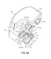
- FIG. 6Ais a section view of an active anti-spill device for a fluid tank of a wet surface cleaning robot.
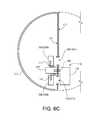
- FIG. 6Bis a schematic top view of an exemplary active anti-spill device having orifice sealers in their closed position.
- FIG. 6Cis a schematic top view of an exemplary active anti-spill device having orifice sealers in their open position.
- FIG. 6Dis a schematic section view of an active anti-spill device for a fluid tank.
- FIG. 6Eis a section view of an active anti-spill device for a fluid tank of a wet surface cleaning robot.
- FIG. 6Fis a top view of an exemplary active anti-spill device having orifice sealers in their open position.
- FIG. 6Gis a top view of an exemplary active anti-spill device having orifice sealers in their closed position.
- FIG. 6His a perspective view of an exemplary liquid cartridge for a wet surface cleaning robot.
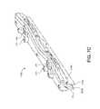
- FIGS. 7A and 7Bare partial section views of the robot shown in FIG. 1 having a smearing element.
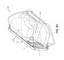
- FIG. 7Cis a perspective view of an exemplary squeegee-fluid applicator module for a wet surface cleaning robot.
- FIG. 7Dis a side view of the squeegee-fluid applicator module shown in FIG. 7C .
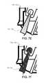
- FIGS. 7E and 7Fare side views of exemplary smearing elements.
- FIG. 8is a schematic view of an exemplary cleaning system for a mobile cleaning robot.
- FIG. 9is schematic view of an exemplary robotic system.
- FIGS. 10 and 11provide exemplary arrangements of operation for methods of operating a mobile surface cleaning robot.
- a mobile autonomous robotcan clean while traversing a surface.
- the robotcan remove wet debris from the surface by agitating the debris and/or wet clean the surface by applying a cleaning liquid to the surface, spreading (e.g., smearing, scrubbing) the cleaning liquid on the surface, and collecting the waste (e.g., substantially all of the cleaning liquid and debris mixed therein) from the surface.
- a robot 100includes a body 110 supported by a drive system 120 that can maneuver the robot 100 across the floor surface 10 based on a drive command having x, y, and ⁇ components, for example.
- the robot body 110has a forward portion 112 and a rearward portion 114 .
- the drive system 120includes right and left driven wheel modules 120 a , 120 b .
- the wheel modules 120 a , 120 bare substantially opposed along a transverse axis X defined by the body 110 and include respective drive motors 122 a , 122 b driving respective wheels 124 a , 124 b .
- the drive motors 122 a , 122 bmay releasably connect to the body 110 (e.g., via fasteners or tool-less connections) with the drive motors 122 a , 122 b optionally positioned substantially over the respective wheels 124 a , 124 b .
- the wheel modules 120 a , 120 bcan be releasably attached to the chassis 110 and forced into engagement with the floor surface 10 by respective springs.
- the robot 100may include a caster wheel 126 disposed to support a forward portion 112 of the robot body 110 .
- the robot body 110supports a power source 102 (e.g., a battery) for powering any electrical components of the robot 100 .
- the wheel modules 120 a , 120 bare movable secured (e.g., rotatably attach) to the robot body 110 and receive spring biasing (e.g., between about 5 and 25 Newtons) that biases the drive wheels 124 a , 124 b downward and away from the robot body 110 .
- spring biasinge.g., between about 5 and 25 Newtons
- the drive wheels 124 a , 124 bmay receive a downward bias about 10 Newtons when moved to a deployed position and about 20 Newtons when moved to a retracted position into the robot body 110 .
- the spring biasingallows the drive wheels to maintain contact and traction with the floor surface 10 while any cleaning elements of the robot 100 contact the floor surface 10 as well.
- the robot 100can move across the floor surface 10 through various combinations of movements relative to three mutually perpendicular axes defined by the body 110 : a transverse axis X, a fore-aft axis Y, and a central vertical axis Z.
- a forward drive direction along the fore-aft axis Yis designated F (sometimes referred to hereinafter as “forward”)
- an aft drive direction along the fore-aft axis Yis designated A (sometimes referred to hereinafter as “rearward”).
- the transverse axis Xextends between a right side R and a left side L of the robot 100 substantially along an axis defined by center points of the wheel modules 120 a , 120 b.
- the robot 100weighs about 40-50 N empty, and 50-60 N when full of water.
- the robot 100may have a center of gravity CG between 0 and 20 mm forward of the transverse axis X (a centerline connecting the drive wheels 124 a , 124 b ).
- the robot 100may rely on having most of its weight over the drive wheels 124 a , 124 b to ensure good traction and mobility on wet surfaces 10 .
- the caster 126 disposed on the forward portion 112 of the robot body 110can support between about 0-10% of the robot's weight.
- the robot 100may include one or more non-driven wheels, such as right and left non-driven wheel 128 a , 128 b rotatably supported by the robot body 110 rearward of the drive wheels 124 a , 124 b for supporting between about 0-10% of the robot's weight and for ensuring the rearward portion 114 of the robot 100 doesn't sit on the ground when accelerating or when water is sloshing around.
- non-driven wheelssuch as right and left non-driven wheel 128 a , 128 b rotatably supported by the robot body 110 rearward of the drive wheels 124 a , 124 b for supporting between about 0-10% of the robot's weight and for ensuring the rearward portion 114 of the robot 100 doesn't sit on the ground when accelerating or when water is sloshing around.
- a forward portion 112 of the body 110carries a bumper 130 , which detects (e.g., via one or more sensors) one or more events in a drive path of the robot 100 , for example, as the wheel modules 120 a , 120 b propel the robot 100 across the floor surface 10 during a cleaning routine.
- the robot 100may respond to events (e.g., obstacles, cliffs, walls) detected by the bumper 130 by controlling the wheel modules 120 a , 120 b to maneuver the robot 100 in response to the event (e.g., away from an obstacle). While some sensors are described herein as being arranged on the bumper, these sensors can be additionally or alternatively arranged at any of various different positions on the robot 100 .
- a user interface 140 disposed on a top portion of the body 110receives one or more user commands and/or displays a status of the robot 100 .
- the user interface 140is in communication with the robot controller 150 carried by the robot 100 such that one or more commands received by the user interface 140 can initiate execution of a cleaning routine by the robot 100 .
- the robot controller 150(executing a control system) may execute behaviors that cause the robot 100 to take an action, such as maneuvering in a wall following manner, a floor scrubbing manner, or changing its direction of travel when an obstacle is detected (e.g., by the bumper sensor system 400 ).
- the robot controller 150can maneuver the robot 100 in any direction across the floor surface 10 by independently controlling the rotational speed and direction of each wheel module 120 a , 120 b .
- the robot controller 150can maneuver the robot 100 in the forward F, reverse (aft) A, right R, and left L directions.
- the robot 100can make repeated alternating right and left turns such that the robot 100 rotates back and forth around the center vertical axis Z (hereinafter referred to as a wiggle motion).
- the wiggle motioncan allow the robot 100 to operate as a scrubber during cleaning operation.
- the wiggle motioncan be used by the robot controller 150 to detect robot stasis.
- the robot controller 150can maneuver the robot 100 to rotate substantially in place such that the robot 100 can maneuver out of a corner or away from an obstacle, for example.
- the robot controller 150may direct the robot 100 over a substantially random (e.g., pseudo-random) path while traversing the floor surface 10 .
- the robot controller 150can be responsive to one or more sensors (e.g., bump, proximity, wall, stasis, and cliff sensors) disposed about the robot 100 .
- the robot controller 150can redirect the wheel modules 120 a , 120 b in response to signals received from the sensors, causing the robot 100 to avoid obstacles and clutter while treating the floor surface 10 . If the robot 100 becomes stuck or entangled during use, the robot controller 150 may direct the wheel modules 120 a , 120 b through a series of escape behaviors so that the robot 100 can escape and resume normal cleaning operations.
- the robot 100includes a cleaning system 160 having a wet cleaning subsystem 200 and/or a dry cleaning subsystem 300 .
- the wet and dry subsystems 200 , 300may operate together or independently. When operating together the two subsystems 200 , 300 share one or more components, such as passageways or a collection bin. In the examples shown, the two subsystems 200 , 300 share one or more components, allowing a lower manufacturing cost and fewer components for servicing.
- the wet cleaning subsystem 200has a liquid volume cartridge 202 disposed on the chassis 110 .
- the liquid volume 202is configured as a removable cartridge received by the chassis 110 .
- the liquid volume cartridge 202includes a supply volume 202 a and a collection volume 202 b , for storing clean fluid and waste fluid, respectively.
- the supply and collection volumesmay be of the same or difference sizes.
- the collection volume 202 bmay be larger than the supply volume 202 a (e.g., by greater than 20%) to accommodate collected debris.
- a useropens a supply port 204 a disposed the supply volume 202 a and pours cleaning fluid into the supply port 204 a in fluid communication with the supply volume 202 a .
- the userthen closes the supply port 204 a (e.g., by tightening a cap over a threaded mouth).
- the usersets the robot 100 on the surface 10 to be cleaned and initiates cleaning by entering one or more commands on the user interface 140 .
- the supply volume 202 a and the collection volume 202 bare configured to maintain a substantially constant center of gravity along the transverse axis X while at least 25% of the total volume of the robot 100 shifts from cleaning liquid in the supply volume 202 a to waste in the collection volume 202 b as cleaning liquid is dispensed from the supply volume 202 a onto the floor surface 10 and then collected as waste with debris in the collection volume 202 b .
- the supply and collection volumes 202 a , 202 bextend along the transverse axis X in substantially equal overlapping extents (e.g., by defining substantially crescent shapes side-by-side).
- all or a portion of the supply volume 202 ais a flexible bladder within the collection volume 202 b and surrounded by the waste collection volume 202 b such that the bladder compresses as cleaning liquid exits the bladder and waste filling the collection volume 202 b takes place of the cleaning liquid that has exited the bladder.
- a systemcan be a self-regulating system which can keep the center of gravity of the robot 100 substantially in place (e.g., over the transverse axis X).
- the bladdercan be full such that the bladder is expanded to substantially fill the collection volume 202 b .
- the volume of the bladderdecreases such that waste entering the collection volume 202 b replaces the displaced cleaning fluid that has exited the flexible bladder.
- the flexible bladderis substantially collapsed within the collection volume 202 b and the collection volume 202 b is substantially full of waste.
- the supply volume 202 a and the collection volume 202 bare defined by substantially crescent or tear drop shaped tanks or compartments arranged side-by-side along the transverse axis X.
- Other configurationsare possible as well, such as stacked compartments (e.g., partially or fully stacked on top of one another), concentric compartments (concentric such that one is inside the other in the lateral direction), interleaved compartments (e.g., interleaved L shapes or fingers in the lateral direction), and so on.
- the robot 100may include a detent mechanism 216 for selectively engaging and disengaging the liquid volume cartridge 202 from the robot body 110 .
- an engagement element 218allows selective engagement of the cleaning cartridge 180 with the robot body 110 .
- the engagement element 218 and/or detentmay provide audible and/or physical verification of successful engagement.
- FIG. 6Adepicts a perspective view of an exemplary liquid volume cartridge 202 having an active anti-spill device 210 that prevents unwanted spillage from the collection volume 202 b of dirty fluid collected from the floor surface 10 when removing the collection volume 202 b from the robot 100 (e.g., for emptying).
- the collection volume 202 bis defined by a collection volume 202 b defining at least one orifice 220 for the flow of fluid into and/or out of the collection volume 202 b .
- the collection volume 202 bmay be removable from the robot 100 , as shown; however, the collection volume 202 b can also be integral with the robot body 110 .
- the anti-spill device 210includes at least one orifice sealer 230 (e.g., a door) that is spring biased to move from an open position that allows fluid to flow through the at least one orifice 220 to a closed position that seals closed the at least one orifice 220 .
- the anti-spill device 210opens the at least one orifice sealer 230 and allows fluid to flow through the at least one orifice 220 .
- the anti-spill device 210causes the at least one orifice sealer 230 to close and seal the at least one orifice 220 , preventing or inhibiting escapement of fluid and/or debris from the collection volume 202 b.
- the collection volume 202 bhas first and second orifices 220 a , 220 b .
- the first orifice 220 ais in fluid communication with a wet vacuum squeegee 206 b and the second orifice 220 b is in fluid communication with an air mover 190 .
- the anti-spill device 210includes first and second orifice sealers 230 a , 230 b configured to cover and seal the first and second orifices 220 a , 220 b , respectively, when the collection volume 202 b is removed from the robot 100 (i.e., in the disengaged position).
- Each orifice sealer 230 , 230 a - bis spring biased to move from an open position to a closed position over a respective orifice 220 , 220 a - b of the collection volume 202 b .
- the orifice sealer(s) 230 , 230 a - bmay be pivotally coupled to an inner surface 221 of the collection volume 202 b adjacent their respective orifices 220 , 220 a - b.
- the example shownillustrates a collection volume 202 b with two orifices 220 , 220 a - b and an anti-spill device 210 with two orifice sealers 230 , 230 a - b that seal both orifices 220 , 220 a - b when the collection volume 202 b is removed from the robot body 110
- the anti-spill device 210may close and seal one or more orifices 220 of the collection volume 202 b using a single orifice sealer 230 .
- the anti-spill device 210includes an orifice opener 240 that moves at least one orifice sealer 230 from the closed position to the open position when the collection volume 202 b is attached to the robot body 110 .
- the orifice opener 240is actuated by an actuator 250 , such as a linear or a rotary actuator.
- the orifice opener actuator 250may be a motor driven linkage system, a solenoid, a lever, etc.
- the orifice opener 240is shown attached to an inner surface 221 of the collection volume 202 b and the orifice opener actuator 250 is shown attached to the an outer surface 223 of the collection volume 202 b ; however, both the orifice opener 240 and the orifice opener actuator 250 may be disposed inside in the collection volume 202 b (e.g., for having the anti-spill device 210 entirely contained within the collection volume 202 b ).
- the orifice opener actuator 250includes a housing 252 that houses and supports a rotary motor 254 having a rotating motor shaft 256 coupled to a cam 258 , which engages and abuts a linear actuator shaft 260 supported to slide longitudinally (i.e., along its longitudinal axis).
- the cam 258rotates about a rotational axis 255 of the rotary motor 254 between an open position and a closed position.
- the cam 258may also have intermediate positions (i.e., for partially open/closed states) as well.
- the actuator shaft 260is supported to slide along its longitudinal axis 261 between corresponding open and closed positions.
- a return spring 264which may be compressed between the actuator housing 252 and a spring catch 262 (e.g., an arm) of the actuator shaft 260 , biases the actuator shaft 260 against the cam 258 . Therefore, as the cam 258 rotates between its open and closed positions, the actuator shaft 260 moves linearly between its corresponding open and closed positions.
- a position sensor 270may detect movement of the cam 258 and/or the actuator shaft 260 between their open and closed positions.
- the position sensor 270includes a first magnetic sensor that detects movement of the cam 258 to its open position and second magnetic sensor that detects movement of the cam 258 to its closed position.
- the position sensor 270includes a magnet attached to the actuator shaft 260 and a magnetic sensor arranged (e.g., parallel to the shaft) to detect movement of the actuator shaft 260 between its open and closed positions.
- the position sensorincludes a magnet attached to the cam 258 and a magnetic sensor arranged (e.g., perpendicular to the axis of rotation of the cam) to detect movement of the cam 258 between its open and closed positions.
- the actuator shaft 260extends from the actuator housing 252 and passes through a shaft hole 224 defined by the collection volume 202 b , which may be sealed about the actuator shaft 260 .
- the actuator shaft 260is received by the orifice opener 240 , which moves the orifice sealer(s) 230 between their open and closed positions.
- the orifice opener 240may include a housing 242 that defines a shaft hole 244 for receiving the actuator shaft 260 .
- the orifice opener housing 242houses and slidably supports a receiver shaft 280 to slide longitudinally (i.e., along its longitudinal axis) and be aligned to receive engagement of the actuator shaft 260 .
- the receiver shaft 280is spring biased toward its closed position.
- a spring 284 compressed between the orifice opener housing 242 and a spring catch 282 (e.g., an arm) of the receiver shaft 280biases the receiver shaft 280 toward its closed position.
- the receiver shaft 280(e.g., an arm thereon) engages a lever arm 246 , which is pivotally supported by the orifice opener housing 242 .
- Each orifice sealer 230is coupled to the lever arm 232 . Movement of the receiver shaft 280 between its open closed positions rotates the lever arm 246 (e.g., via a shaft arm 286 ) as well as the coupled orifice sealer(s) 230 between their open and closed positions, respectively.
- the active anti-spill device 210receives commands for opening and closing the orifice sealer(s) 230 from the robot controller 150 or a dedicated anti-spill controller 290 (e.g., having a computing process and memory), which communicates with the robot controller 150 .
- a dedicated anti-spill controller 290e.g., having a computing process and memory
- the tank orifices 220 of the collection volume 202 bcan be closed.
- the robot controller 150may issue a command to the anti-spill device 210 to move the orifice sealer(s) 230 to its/their closed position.
- the rotary motor 254moves the cam 258 to its closed position (as sensed by the position sensor 270 ), which moves the actuator shaft 260 , receiving shaft 280 , lever arm 246 , and orifice sealer(s) 230 all to their closed positions, causing the orifice sealer(s) 230 to seal over its/their respective orifice(s) 220 , preventing or inhibiting fluid flow therethrough.
- first and second orifice sealer(s) 230 a - bwhen they are in their closed positions, they seal closed the first and second orifices 220 a - b , respectively, preventing the flow of air and fluid therethrough.
- the orifices 220 , 220 a - b of the collection volume 202 bmay be open to allow the flow of air into and out of the collection volume 202 b and dirty fluid into the collection volume 202 b .
- the robot controller 150issues a command to the anti-spill device 210 causing opening of the orifice sealer(s) 230 , 230 a - b , which opens the orifices 220 , 220 a - b .
- the rotary motor 254moves the cam 258 to its open position (as sensed by the position sensor 270 ), which moves the actuator shaft 260 , receiving shaft 280 , lever arm 246 , and orifice sealer(s) 230 , 230 a - b all to their open positions.
- the orifice opener actuator 250With the orifice opener actuator 250 in its open state, the return spring 284 between the orifice opener housing 242 and the spring catch 282 of the receiver shaft 280 is compressed, biasing the receiver shaft 280 for movement to its closed position once it is no longer held in its open position by the actuator shaft 260 .
- the orifices 220 , 220 a - b of collection volume 202 bmay be closed again.
- the robot controller 150may issue a command to the anti-spill device 210 to move the orifice sealer(s) 230 , 230 a - b to its/their closed position again.
- the robot controller 150may issue a command to the anti-spill device 210 to close the orifices 220 , 220 a - b of the collection volume 202 b . If the collection volume 202 b is removable from the robot body 110 and is removed when the tank orifices 220 , 220 a - b are open, the robot controller 150 may receive a signal from a collection volume removal sensor (e.g., contact sensor, switch, proximity sensor, etc.) indicating removal of the collection volume.
- a collection volume removal sensore.g., contact sensor, switch, proximity sensor, etc.
- the robot controller 150may issue a command to the anti-spill device 210 to close the orifices 220 , 220 a - b of the collection volume 202 b .
- the actuator shaft 260slides out of the collection volume 202 b and orifice opener housing 242 , disengaging from the receiver shaft 280 .
- the compressed return spring 284extends, maintaining contact between the actuator shaft 260 and the receiver shaft 280 until the receiver shaft 280 is in the closed position.
- the receiver shaft 280rotates the lever arm 246 , moving the orifice sealer(s) 230 , 230 a - b to their closed positions, closing the tank orifices 220 , 220 a - b .
- the return spring 284presses against the receiver shaft 280 causing compression of the orifice sealer(s) 230 , 230 a - b , via the lever arm 246 , against the inner surface 221 of the collection volume 202 b .
- the orifice sealers 230are shown as pivoting between their open and closed positions, they can also move linearly or along any other path of movement.
- the robot controller 150may stop movement of the robot 100 and provide an alert (e.g., a visual alert or an audible alert) to the user via the user interface 140 .
- the usercan then open a port 166 defined by the collection volume 202 b to remove collected waste therein.
- the liquid volume cartridge 202isolates substantially the entire electrical system of the robot 100 from carried fluid.
- sealingthat can be used to separate electrical components of the robot 100 from the cleaning liquid and/or waste include application of the super-hydrophobic coating or treatment, covers, plastic or resin modules, potting, shrink fit, gaskets, or the like. Any and all elements described herein as a circuit board, PCB, detector, or sensor can be sealed using the super-hydrophobic coating or treatment or any of various different methods.
- electrical components and/or components in intermediate contact with electrical componentscan receive the super-hydrophobic coating or treatment to prevent conveyance of fluid to the electrical components.
- the anti-spill device 210includes at least one orifice sealer 230 , 230 a - b (e.g., a door) that is spring biased (e.g., by a spring 284 ) to move from an open position that allows fluid to flow through the at least one orifice 220 , 220 a - b to a closed position that seals closed the at least one orifice 220 , 220 a - b .
- the anti-spill device 210includes first and second orifice sealers 230 a , 230 b that each pivot at a proximal end 231 between the open and closed positions.
- a frame 212may support the orifice sealers 230 a , 230 b at their proximal ends 231 and optionally engage the springs 284 .
- the frame 212may support a filter 214 and/or be configured to direct liquid away from the port 166 . This can prevent dirty liquid from being sucked out of the collection volume 202 b during operation.
- a protrusion 234(e.g., disposed on the robot body 110 ) opens the orifice sealer 230 , 230 a - b and allows fluid to flow through the corresponding orifice 220 .
- the anti-spill device 210causes the orifice sealer(s) 230 , 230 a - b to close (e.g., via spring bias) and seal the corresponding orifice(s) 220 , 220 a - b , preventing or inhibiting escapement of fluid and/or debris from the collection volume 202 b.
- the liquid volume cartridge 202includes the pump 172 , which may include a snorkel 171 arranged to suck liquid from a top portion of the supply volume 202 a , since the cleanest liquid typically is at the top, while dirt generally settles toward the bottom.
- the pump 172may include a snorkel 171 arranged to suck liquid from a top portion of the supply volume 202 a , since the cleanest liquid typically is at the top, while dirt generally settles toward the bottom.
- the wet cleaning system 160may include a fluid applicator 170 a in fluid communication with the supply volume 202 a and carried by the robot body 110 rearward of the dry cleaning subsystem 300 .
- the fluid applicator 170 aextends along the transverse axis X and dispenses cleaning liquid 12 onto the surface 10 during wet vacuuming rearward of any vacuuming components to allow the dispensed fluid to dwell on the floor surface 10 .
- a vacuum assemblysucks up previously dispensed liquid and debris suspended therein.
- a pump 172forces cleaning liquid through the fluid applicator 170 a and out of a fluid disperser 174 defined by or disposed on the fluid applicator 170 a .
- the fluid disperser 174may be a series of orifices 174 a , as shown in FIGS. 2 , 7 A, and B, spaced substantially equidistantly along the applicator 170 a to produce a substantially uniform spray pattern of cleaning liquid onto the floor surface 10 .
- the fluid disperser 174may be configured as an accumulator 174 b to direct a flow of liquid 12 onto and/or into a smearing element 176 of the fluid applicator 170 a .
- the fluid accumulator 174 bengages with the smearing element 176 to form an accumulator volume 173 in which fluid 12 accumulates.
- the fluid 12is pumped from the supply volume 202 a and delivered to the accumulator 174 b by one or more lumens 177 .
- the accumulator 174 bmay be formed as a clip (e.g., out of sheet metal or plastic) that pinches down on the smearing element 176 .
- the accumulator 174 bhas a sidewall 175 angled downward toward the smearing element 176 at angle of about 45 degrees to increase the contact area between the smearing element 176 and fluid 12 accumulated within the accumulator volume 173 .
- the angled sidewall 175further assists with directing the fluid 12 into the smearing element 176 .
- fluid 12escapes through the smearing element 176 .
- the accumulator 174 btherefore retains pressurized fluid 12 in direct contact with a top portion of the smearing element 176 disposed within the accumulator volume 173 , thereby causing fluid 12 to flow into the smearing element 176 .
- the fluid 12flows through the smearing element for deposition on the floor surface 10 under the force(s) of pressure, gravity and/or capillary action, and the smearing element 176 wicks, absorbs, or accumulates fluid 12 for application onto the floor surface 10 .
- the fluid applicator 170 aincludes a smearing element 176 , such as bristle brush 176 a ( FIG. 7E ) or continuous element 176 b ( FIG. 7F ) (e.g., a sponge or a microfiber cloth) that directs fluid 12 onto the floor surface 12 via capillary action.
- the smearing element 176smears or applies a dispensed fluid 12 on the floor surface 10 . leaving a smooth sheen or film 14 of fluid 12 .
- the smearing element 176may extend along substantially an entire width of the robot 100 (along the X axis) or a portion thereof rearward of the drive wheel modules 120 a , 120 b , an entire length of the fluid applicator 170 a , or only a portion of the fluid applicator 170 a.
- the smearing element 176is arranged (e.g., below the fluid disperser 174 a ) such that the fluid applicator 170 a dispenses fluid 12 forward of and/or onto the smearing element 176 , which absorbs the fluid 12 and smears it onto the floor surface 10 .
- the fluid disperser 174 amay define a lumen 177 (e.g., therethrough or partially therethrough) in fluid communication with the supply volume 202 a , as shown in FIG. 7B .
- the smearing element 176absorbs the fluid 12 and/or allows the fluid 12 to pass to its outer surface 178 for application onto the floor surface 10 .
- the smearing element 176may provide relatively more even fluid dispersion onto the floor surface 10 compared to fluid application directly onto the floor surface 10 alone from the fluid dispenser 174 a .
- the smearing element 176can agitate or scrub the floor surface 10 , as the robot 100 moves over the floor surface 10 .
- the cleaning system 160includes a squeegee-fluid applicator module 170 b , which includes the smearing element 176 , the accumulator 174 b and a wet vacuum squeegee 206 b .
- the robot 100pumps fluid 12 in to the accumulator volume 173 of squeegee-fluid applicator module 170 b through the one or more lumens 177 .
- the fluid 12travels the length of the smearing element 176 within the accumulator volume 173 defined by the accumulator 174 b and the smearing element 176 held therein.
- the accumulator 174 bpinches the bristles together tightly so that the fluid 12 entering the accumulator volume 173 travels along the length of the smearing element 176 rather than immediately flowing between the bristles and onto a surface below the smearing element 176 .
- the accumulator 174 bis filled with fluid 12 , pressure increases within the accumulator 174 b and the fluid 12 therein starts being forced out of the accumulator volume 173 and into the bristles of the smearing element 176 .
- the smearing element 176is uniformly wetted along its length and therefore deposits a smooth sheen of water on the floor, which leads to even cleaning and prevents streaking.
- the smearing element 176is disposed rearward of the wet vacuum squeegee 206 b , with respect to the forward drive direction F, so that fluid dispersed on the floor surface 10 may have a dwell time before being picked up again by the cleaning system 160 , if and when the robot 100 re-traverses that location of the floor surface 10 .
- the squeegee-fluid applicator module 170 bmay define one or more ports for delivering fluid and one or more ports for returning collected debris.
- the squeegee-fluid applicator module 170 bincludes one or more fluid lumens 177 that receive fluid 12 into the accumulator 174 b and one or more vacuum ports 179 for guiding a flow of evacuated fluid and/or debris from the wet vacuum squeegee 206 b out of the squeegee-fluid applicator module 170 b .
- the vacuum port(s) 179connect(s) to a cleaning cartridge 180 .
- the wet vacuum squeegee 206 bmay include first and second squeegee blades 205 a , 205 b arranged to gather or collect dwelled fluid 12 and/or debris therebetween for evacuation off of the floor surface 10 .
- the squeegee blades 205 a , 205 bmay be arranged parallel or non-parallel to one another and to the smearing element 176 .
- the squeegee blades 205 a , 205 bmay be linear, curvilinear, or define some other shape conducive for evacuating fluid 12 and/or debris off of the floor surface 10 .
- the cleaning cartridge 180 carried by the robot 100lifts waste from the floor surface 10 and into the collection volume 202 b of the robot 100 , leaving behind a wet vacuumed floor surface 10 .
- the cleaning cartridge 180includes components of both the wet cleaning subsystem 200 and the dry cleaning subsystem 300 .
- the wet cleaning system 200may include a wet vacuum squeegee 206 b disposed on the cleaning cartridge 180 or the robot body 110 forward of the fluid applicator 170 a and extend from the bottom surface 116 of the robot body 110 to movably contact the floor surface 10 .
- the wet vacuum squeegee 206 bmay be positioned forward or rearward of the wheel modules 120 a , 120 b .
- a rearward positioning of the wet vacuum squeegee 206 bcan reduce rearward tipping of the robot 100 in response to thrust created by the wheel modules 120 a , 120 b propelling the robot 100 in a forward direction.
- the movable contact between the wet vacuum squeegee 206 b and floor surface 10acts to lift waste (e.g., a mixture of cleaning liquid and debris) from the floor surface 10 as the robot 100 is propelled in the forward direction.
- the wet cleaning system 200includes dry and wet vacuum squeegees 206 a , 206 b in fluid communication via ducting 208 with an air mover 190 (e.g., fan) and the collection volume 202 b .
- the air mover 190creates a low pressure region along its fluid communication path including the collection volume 202 b and the vacuum squeegees 206 a , 206 b .
- the air mover 190creates a pressure differential across the vacuum squeegees 206 a , 206 b , resulting in suction of waste from the floor surface 10 and through the dry and wet vacuum squeegees 206 a , 206 b .
- the dry and wet vacuum squeegees 206 a , 206 bare disposed on the cleaning cartridge 180 with the first vacuum squeegee 206 a forward of the second vacuum squeegee 206 b .
- the dry vacuum squeegee 206 ais disposed on forward portion 112 of the robot body 110
- the wet vacuum squeegee 206 bis disposed on rearward portion 114 of the robot body 110 .
- the wet cleaning system 200includes first and second ducts 208 a , 208 b in fluid communication with the dry and wet vacuum squeegees 206 a , 206 b , respectively.
- the two conduits 208 a , 208 bmerge to form a common conduit 208 c that is in fluid communication with the air mover 190 and the collection volume 202 b .
- the dry vacuum squeegee 206 amay include first and second blowers 207 a , 207 b disposed opposite each other and arranged to move debris to first duct 208 a centrally located along the dry vacuum squeegee 206 a .
- a spring biased suspension 209may support the wet vacuum squeegee 206 b and apply a downward force (e.g., between about 1 and 5 Newtons) that ensures contact between the wet vacuum squeegee 206 b and the floor surface 10 without creating excess frictional drag.
- the dry vacuum squeegee 206 a and corresponding duct 208 areceive a flow of primarily dirty air, while the wet vacuum squeegee 206 b and corresponding duct 208 b receive a flow of primarily dirty water.
- the robot 100may include a dry cleaning system 300 having a roller brush 310 (e.g., with bristles and/or beater flaps) extending parallel to the transverse axis X and rotatably supported by the cleaning cartridge 180 (or, alternatively, the robot body 110 ) to contact the floor surface 10 rearward of the dry vacuum squeegee 206 a and forward of the wet vacuum squeegee 206 b of the wet cleaning system 200 .
- the roller brush 310may be driven by a corresponding brush motor 312 or by one of the wheel drive motors 122 a , 122 b (e.g., using a gearbox 314 ).
- the driven roller brush 310agitates debris (and applied fluid) on the floor surface 10 , moving the debris into a suction path of at least one of the vacuum squeegees 206 a , 206 b (e.g., a vacuum or low pressure zone) for evacuation to the collection volume 202 b . Additionally or alternatively, the driven roller brush 310 may move the agitated debris off the floor surface 10 and into a collection bin (not shown) adjacent the roller brush 310 or into one of the ducting 208 . The roller brush 310 may rotate so that the resultant force on the floor 10 pushes the robot 100 forward.
- the cleaning system 160combines wet and dry debris flows into a single common passageway or conduit 208 c in fluid communication with an inlet or orifice 220 b of the collection volume 202 b , allowing the dry, solid debris to be deposited in the same collection volume 202 b as the liquid debris.
- the aircan expand and slow inside the collection volume 202 b which causes the debris to fall out of the flow(s), before sucking the air out of the collection volume 202 b through an outlet or orifice 220 a using the air mover 190 .
- the outlet orifice 220 ais behind a filter 222 , which prevents debris from being sucked into the air mover 190 .
- the orifices 220may have features that prevent water from sloshing out of the collection volume 202 b when the robot accelerates or decelerates.
- the cleaning cartridge 180may releasable connect to the robot body 110 and/or the cleaning system 160 to allow removal by the user to clean any accumulated dirt or debris from within the cleaning cartridge 180 .
- a usercan remove the cleaning cartridge 180 (e.g., by releasing tool-less connectors or fasteners) for rinsing in a sink.
- all of the cleaning head mechanisms and ductingare located within the single removable cleaning cartridge 180 , or cleaning cartridge, which can be removed in its entirety and rinsed out under a sink, making it very easy for the user to clean the dirtiest parts of the robot 100 .
- the removed cleaning cartridge 180 , or cleaning cartridgepresents the dirty water connection to the liquid volume cartridge 202 (also referred to as a tank), and it may be possible to clean the wet cleaning subsystem 200 by pouring water through the ports or orifices 220 , flushing out the system.
- the brush 310 and wet vacuum squeegee 206 bcan be removed from the cleaning cartridge 180 allowing the user to clean those independently as well.
- a latching system 182may allow both easy removal of the cleaning cartridge 180 , or vacuum module, from the robot 100 and easy attachment back onto the robot 100 by guiding the cleaning cartridge 180 for proper location during reassembly.
- the latching system 182may include one or more guide connectors 184 disposed on the cleaning cartridge 180 that are received by and releasably connect to the robot body 110 . Locating receptacles 118 defined by the robot body 110 (or another portion of the robot 100 ) receive the respective guide connectors 184 . When the user releases the guide connector(s) 184 , the cleaning cartridge 180 releases away from the robot body 110 for servicing.
- a latchmay release all of the guide connectors 184 simultaneously.
- the usermay reattach the cleaning cartridge 180 onto the robot by locating the guide connectors 184 in their respective receptacles 118 and pushing the cleaning cartridge 180 onto the robot 100 until secured (e.g., clicking into place with via the latching system 182 ).
- the latching system 182holds the cleaning cartridge 180 firmly against any gaskets and/or conduit connections to form an air-tight and water-tight seal, preventing any leaking therefrom.
- the single common passageway or conduit 208 ctherefore forms a fluid-tight interface with the inlet or orifice 220 b of the collection volume 202 b when the cleaning cartridge 180 mates with the robot body 110 .
- the cleaning cartridge 180may include the rotating brush 310 of the dry cleaning sub-system 300 .
- the gearbox 314 driving the brush 310may be disposed on the cleaning cartridge 180 and provide a geared interface 316 with the brush motor 312 disposed on the robot body 110 .
- the brush motor 312 and electronicsstay on the robot body 110 (away from water rinsing of the vacuum assembly 180 ).
- the guide connectors 184properly orient and locate the gearbox 314 with the brush motor 312 so that the geared interface has properly engaged gears.
- the robot 100may include a sensor system 500 having several different types of sensors which can be used in conjunction with one another to create a perception of the robot's environment sufficient to allow the robot 100 to make intelligent decisions about actions to take in that environment.
- the sensor system 500may include one or more types of sensors supported by the robot body 110 , which may include obstacle detection obstacle avoidance (ODOA) sensors, communication sensors, navigation sensors, etc.
- ODOAobstacle detection obstacle avoidance
- these sensorsmay include, but not limited to, proximity sensors, contact sensors, a camera (e.g., volumetric point cloud imaging, three-dimensional (3D) imaging or depth map sensors, visible light camera and/or infrared camera), sonar, radar.
- the sensor system 500includes ranging sonar sensors, proximity cliff detectors, contact sensors, a laser scanner, and/or an imaging sonar.
- the sensorsneed to be placed such that they have maximum coverage of areas of interest around the robot 100 .
- the sensorsmay need to be placed in such a way that the robot 100 itself causes an absolute minimum of occlusion to the sensors; in essence, the sensors cannot be placed such that they are “blinded” by the robot itself.
- the placement and mounting of the sensorsshould not be intrusive to the rest of the industrial design of the platform. In terms of aesthetics, it can be assumed that a robot with sensors mounted inconspicuously is more “attractive” than otherwise. In terms of utility, sensors should be mounted in a manner so as not to interfere with normal robot operation (snagging on obstacles, etc.).
- the sensor system 500one or more proximity sensors 410 and bump or contact sensor 420 in communication with the robot controller 150 and arranged in one or more zones or portions of the robot 100 (e.g., disposed around a perimeter of the robot body 110 ) for detecting any nearby or intruding obstacles.
- the proximity sensorsmay be converging infrared (IR) emitter-sensor elements, sonar sensors, ultrasonic sensors, and/or imaging sensors (e.g., 3D depth map image sensors) that provide a signal to the controller 150 when an object is within a given range of the robot 100 .
- one or more of the proximity sensors 410can be arranged to detect when the robot 100 has encountered a falling edge of the floor, such as when it encounters a set of stairs.
- a cliff proximity sensor 410 bcan be located at or near the leading end and the trailing end of the robot body 110 .
- the robot controller 150(executing a control system) may execute behaviors that cause the robot 100 to take an action, such as changing its direction of travel, when an edge is detected.
- the bumper 130includes an array of wall proximity sensors 410 a (e.g., 10 wall proximity sensors 410 a ) arranged evenly along a forward perimeter of the bumper 130 and directed outward substantially parallel with the floor surface 10 for detecting nearby walls.
- the bumper sensor system 400also includes one or more cliff proximity sensors 410 b (e.g., four cliff proximity sensors 410 b ) arranged to detect when the robot 100 encounters a falling edge of the floor 10 , such as when it encounters a set of stairs.
- the cliff proximity sensor(s) 410 bcan point downward and be located on a lower portion 132 of the bumper 130 near a leading edge 136 of the bumper 130 and/or in front of one of the drive wheels 124 a , 124 b .
- cliff and/or wall sensingis implemented using infrared (IR) proximity or actual range sensing, using an infrared emitter and an infrared detector angled toward each other so as to have an overlapping emission and detection fields, and hence a detection zone, at a location where a floor should be expected.
- IR proximity sensingcan have a relatively narrow field of view, may depend on surface albedo for reliability, and can have varying range accuracy from surface to surface.
- multiple discrete cliff proximity sensors 410 bcan be placed about the perimeter of the robot 100 to adequately detect cliffs from multiple points on the robot 100 .
- the robot 100includes a navigation system 600 configured to allow the robot 100 to deposit cleaning liquid on a surface and subsequently return to collect the cleaning liquid from the surface through multiple passes.
- the multi-pass configurationallows cleaning liquid to be left on the surface for a longer period of time while the robot 100 travels at a higher rate of speed.
- the navigation system 600allows the robot 100 to return to positions where the cleaning fluid has been deposited on the surface but not yet collected.
- the navigation system 600can maneuver the robot 100 in a pseudo-random pattern across the floor surface 10 such that the robot 100 is likely to return to the portion of the floor surface 10 upon which cleaning fluid has remained.
- the navigation system 600may be a behavior based system stored and/or executed on the robot controller 150 .
- the navigation system 600may communicate with the sensor system 500 to determine and issue drive commands to the drive system 120 .
- FIG. 10provides an exemplary arrangement 1000 of operation for a method of operating a mobile surface cleaning robot 100 .
- the methodincludes detecting 1002 an operating state of the robot 100 and in response to detecting a cleaning state of the robot 100 , moving 1004 an orifice sealer 230 of an orifice 220 of the collection volume 202 b of the robot 100 to an open position, allowing a flow of fluid through the orifice 220 .
- the methodfurther includes, in response to detecting a non-cleaning state of the robot 100 , moving 1006 the orifice sealer 230 to a closed position, preventing any flow of fluid through the orifice 220 .
- the methodincludes detecting the cleaning state by receiving a signal indicating execution of a cleaning operation.
- the methodmay include detecting the non-cleaning state by receiving a signal indicating at least one of cessation of the cleaning operation, a wheel drop condition, a cliff detection (e.g., via a cliff sensor 410 b ), robot removal from a floor surface 10 (e.g., via a cliff sensor 410 b , wheel drop sensor, and/or an inertial measurement unit), or detachment of the collection volume 202 b from the robot 100 .
- a signal indicating execution of a cleaning operationmay include detecting the non-cleaning state by receiving a signal indicating at least one of cessation of the cleaning operation, a wheel drop condition, a cliff detection (e.g., via a cliff sensor 410 b ), robot removal from a floor surface 10 (e.g., via a cliff sensor 410 b , wheel drop sensor, and/or an inertial measurement unit),
- the non-cleaning statecan be detected by receiving a first signal indicating attachment of the collection volume 202 b to the robot 100 in combination with a second signal indicating non-execution of a cleaning operation. This may occur when a user reattaches the collection volume 202 , 202 b after servicing.
- the methodincludes moving an actuator shaft 260 longitudinally between open and closed positions through an aperture 224 defined by the collection volume 202 b .
- the actuator shaft 260causes movement of the orifice sealer 230 between its corresponding open and closed positions.
- the methodmay also include rotating a cam 258 that moves the actuator shaft 260 longitudinally between open and closed positions, causing corresponding movement of the orifice sealer 230 between its open and closed positions.
- the methodsometimes includes allowing spring biased movement of the orifice sealer 230 to its close position upon movement of the actuator shaft 260 to its closed position (or removal of the actuator shaft 260 ).
- FIG. 11provides another exemplary arrangement 1100 of operation for a method of operating a mobile surface cleaning robot 100 .
- the methodincludes blowing 1102 air onto a floor surface 10 beneath the robot 100 , lifting 1104 substantially dry debris from the floor surface 10 into a first duct 208 a , and dispensing 1106 fluid 12 onto the floor surface 10 .
- the methodalso includes lifting 1108 at least one of fluid 12 or wet debris from the floor surface 10 into a second duct 208 b , and moving 1110 a flow debris from the first duct 208 a and a flow of the at least one of fluid 12 or wet debris from the second duct 208 b both through a third duct 208 c into a collection volume 202 b.
- the methodincludes allowing an expansion of air in the collection volume 202 b to allow debris to settle into the collection volume 202 b .
- the methodmay include evacuating air from the collection volume 202 b .
- the methodmay include blowing the air from opposite directions toward the first duct 208 a centrally located on the robot 100 .
- the methodmay include dispensing the fluid 12 onto the floor surface 10 rearward of blowing air onto the floor surface 10 and rearward of lifting the substantially dry debris from the floor surface 10 .
- the methodmay include dispensing the fluid 12 onto the floor surface 10 rearward lifting the at least one of fluid 12 or wet debris from the floor surface 10 .
- the methodmay include smearing the dispensed fluid 12 onto the floor surface 10 .
- the methodmay include filtering the evacuated air from the collection bin 202 b.
Landscapes
- Cleaning Implements For Floors, Carpets, Furniture, Walls, And The Like (AREA)
- Manipulator (AREA)
- Electric Vacuum Cleaner (AREA)
Abstract
Description
Claims (19)
Priority Applications (4)
| Application Number | Priority Date | Filing Date | Title |
|---|---|---|---|
| US13/729,819US9282867B2 (en) | 2012-12-28 | 2012-12-28 | Autonomous coverage robot |
| EP13869085.4AEP2846672B1 (en) | 2012-12-28 | 2013-08-29 | Autonomous coverage robot |
| PCT/US2013/057325WO2014105221A1 (en) | 2012-12-28 | 2013-08-29 | Autonomous coverage robot |
| JP2015512920AJP5928656B2 (en) | 2012-12-28 | 2013-08-29 | Autonomous coverage robot |
Applications Claiming Priority (1)
| Application Number | Priority Date | Filing Date | Title |
|---|---|---|---|
| US13/729,819US9282867B2 (en) | 2012-12-28 | 2012-12-28 | Autonomous coverage robot |
Publications (2)
| Publication Number | Publication Date |
|---|---|
| US20140182627A1 US20140182627A1 (en) | 2014-07-03 |
| US9282867B2true US9282867B2 (en) | 2016-03-15 |
Family
ID=51015745
Family Applications (1)
| Application Number | Title | Priority Date | Filing Date |
|---|---|---|---|
| US13/729,819Active2033-03-27US9282867B2 (en) | 2012-12-28 | 2012-12-28 | Autonomous coverage robot |
Country Status (4)
| Country | Link |
|---|---|
| US (1) | US9282867B2 (en) |
| EP (1) | EP2846672B1 (en) |
| JP (1) | JP5928656B2 (en) |
| WO (1) | WO2014105221A1 (en) |
Cited By (11)
| Publication number | Priority date | Publication date | Assignee | Title |
|---|---|---|---|---|
| US9902477B1 (en) | 2016-11-04 | 2018-02-27 | Aqua Products, Inc. | Drive module for submersible autonomous vehicle |
| US10301837B2 (en) | 2016-11-04 | 2019-05-28 | Aqua Products, Inc. | Drive module for submersible autonomous vehicle |
| US10407931B2 (en) | 2016-09-02 | 2019-09-10 | Aqua Products, Inc. | Modular swimming pool cleaner |
| US20210030232A1 (en)* | 2019-07-31 | 2021-02-04 | Lg Electronics Inc. | Cleaner |
| US20210251452A1 (en)* | 2018-08-07 | 2021-08-19 | Koninklijke Philips N.V. | Wet cleaning device |
| US11219347B2 (en) | 2017-12-22 | 2022-01-11 | Bissell Inc. | Robotic cleaner |
| US11317779B2 (en) | 2017-12-22 | 2022-05-03 | Bissell Inc. | Robotic cleaner with sweeper and rotating dusting pads |
| US11638512B2 (en)* | 2020-04-24 | 2023-05-02 | Lg Electronics Inc. | Robot cleaner |
| USD998922S1 (en)* | 2021-08-23 | 2023-09-12 | Beijing Roborock Technology Co., Ltd. | Water tank for a cleaning robot |
| USD1000741S1 (en)* | 2021-02-10 | 2023-10-03 | Beijing Roborock Technology Co., Ltd. | Water tank for a cleaning robot |
| USD1004742S1 (en)* | 2019-09-05 | 2023-11-14 | Beijing Roborock Technology Co., Ltd. | Water tank |
Families Citing this family (63)
| Publication number | Priority date | Publication date | Assignee | Title |
|---|---|---|---|---|
| KR102021894B1 (en)* | 2012-10-18 | 2019-11-04 | 엘지전자 주식회사 | Method of controlling an automatic cleaner |
| US20140208527A1 (en)* | 2013-01-25 | 2014-07-31 | Ching-Chi Lin | Automatic floor sweeping and mopping device |
| US9988173B2 (en)* | 2013-09-27 | 2018-06-05 | 3M Innovative Properties Company | Method of robot assisted automated decal application on complex three dimensional surfaces |
| EP2912981B1 (en) | 2014-02-28 | 2019-09-04 | Samsung Electronics Co., Ltd. | Autonomous cleaner |
| CA160345S (en)* | 2014-08-01 | 2015-10-06 | Toshiba Kk | Autonomous coverage vacuum cleaner |
| KR101622716B1 (en)* | 2014-09-24 | 2016-05-19 | 엘지전자 주식회사 | Robot cleaner |
| KR101622713B1 (en) | 2014-09-24 | 2016-05-19 | 엘지전자 주식회사 | Robot cleaner |
| CN205493720U (en) | 2014-11-26 | 2016-08-24 | Lg电子株式会社 | Robot cleaner |
| KR101641262B1 (en)* | 2014-12-01 | 2016-07-20 | 엘지전자 주식회사 | Robot cleaner |
| KR102266928B1 (en) | 2014-12-02 | 2021-06-18 | 엘지전자 주식회사 | Mop module and robot cleaner having the same |
| US9757004B2 (en)* | 2015-02-12 | 2017-09-12 | Irobot Corporation | Liquid management for floor-traversing robots |
| USD778515S1 (en)* | 2015-04-23 | 2017-02-07 | Samsung Electronics Co., Ltd. | Robot cleaner |
| USD785261S1 (en)* | 2015-04-23 | 2017-04-25 | Samsung Electronics Co., Ltd. | Robot cleaner |
| USD779750S1 (en)* | 2015-04-23 | 2017-02-21 | Samsung Electronics Co., Ltd. | Robot cleaner |
| DE102015108534A1 (en)* | 2015-05-29 | 2016-12-01 | Vorwerk & Co. Interholding Gmbh | Cleaning device with a cleaning roller |
| CN106419766B (en)* | 2015-08-10 | 2020-06-26 | 科沃斯机器人股份有限公司 | Self-moving cleaning robot |
| KR101692736B1 (en) | 2015-08-24 | 2017-01-04 | 엘지전자 주식회사 | Robot cleaner |
| KR101692737B1 (en)* | 2015-09-23 | 2017-01-04 | 엘지전자 주식회사 | Robot Cleaner |
| RU2710413C1 (en) | 2016-05-20 | 2019-12-26 | ЭлДжи ЭЛЕКТРОНИКС ИНК. | Robot vacuum cleaner |
| WO2017200349A1 (en) | 2016-05-20 | 2017-11-23 | 엘지전자 주식회사 | Robot cleaner |
| US10342405B2 (en) | 2016-05-20 | 2019-07-09 | Lg Electronics Inc. | Autonomous cleaner |
| WO2017200346A1 (en) | 2016-05-20 | 2017-11-23 | 엘지전자 주식회사 | Robot cleaner |
| WO2017200343A1 (en) | 2016-05-20 | 2017-11-23 | 엘지전자 주식회사 | Robot cleaner |
| WO2017200345A1 (en) | 2016-05-20 | 2017-11-23 | 엘지전자 주식회사 | Robot cleaner |
| WO2017200347A1 (en) | 2016-05-20 | 2017-11-23 | 엘지전자 주식회사 | Robot cleaner |
| WO2017200350A1 (en) | 2016-05-20 | 2017-11-23 | 엘지전자 주식회사 | Robot cleaner |
| WO2017200344A1 (en) | 2016-05-20 | 2017-11-23 | 엘지전자 주식회사 | Robot cleaner |
| WO2017200353A1 (en) | 2016-05-20 | 2017-11-23 | 엘지전자 주식회사 | Robot cleaner |
| US10463221B2 (en) | 2016-05-20 | 2019-11-05 | Lg Electronics Inc. | Autonomous cleaner |
| CN108024680B (en) | 2016-08-30 | 2021-01-15 | 深圳市智意科技有限公司 | Sewage tank sealing structure |
| DE102016118650A1 (en)* | 2016-09-30 | 2018-04-05 | Vorwerk & Co. Interholding Gmbh | Self-propelled surface treatment device |
| US10732127B2 (en)* | 2016-10-26 | 2020-08-04 | Pixart Imaging Inc. | Dirtiness level determining system and surface cleaning machine |
| CN207996183U (en)* | 2017-01-17 | 2018-10-23 | 美国iRobot公司 | Mobile clean robot |
| CN208582332U (en)* | 2017-01-26 | 2019-03-08 | 深圳洛克时代科技有限公司 | Intelligent cleaning equipment water tank and intelligent cleaning equipment |
| CN108451447B (en) | 2017-02-17 | 2024-06-04 | 科沃斯机器人股份有限公司 | Cleaning robot |
| CN107307798A (en) | 2017-08-03 | 2017-11-03 | 深圳市银星智能科技股份有限公司 | Mobile robot |
| US12426753B2 (en) | 2017-11-16 | 2025-09-30 | Irobot Corporation | Washable bin for a robot vacuum cleaner |
| USD828529S1 (en)* | 2017-12-21 | 2018-09-11 | Ningbo Zhekai Electric Co., Ltd. | Air purifier |
| US10806314B2 (en) | 2018-01-05 | 2020-10-20 | Irobot Corporation | Wet floorcare robot cleaner tank latch |
| TWI677378B (en)* | 2018-05-30 | 2019-11-21 | 國家中山科學研究院 | Intelligent programmable self-propelled mist waterfall fluid cleaning device |
| JP7135567B2 (en)* | 2018-08-10 | 2022-09-13 | オムロン株式会社 | relay |
| CN109171570B (en)* | 2018-09-10 | 2020-10-23 | 浙江龙力科技股份有限公司 | Sweeping and mopping integrated robot |
| KR102269273B1 (en) | 2019-07-31 | 2021-06-29 | 엘지전자 주식회사 | Robot Cleaner |
| KR102279788B1 (en) | 2019-07-31 | 2021-07-19 | 엘지전자 주식회사 | Robot Cleaner |
| CN112568812A (en)* | 2019-09-29 | 2021-03-30 | 北京石头世纪科技股份有限公司 | Driving wheel module and self-moving robot |
| US20230012561A1 (en)* | 2019-12-20 | 2023-01-19 | Techtronic Cordless Gp | A cleaner head for a cleaning appliance |
| CN111466835A (en)* | 2020-03-31 | 2020-07-31 | 深圳市银星智能科技股份有限公司 | Cleaning robot |
| CN111345748B (en)* | 2020-04-30 | 2025-05-13 | 深圳银星智能集团股份有限公司 | Cleaning Robot |
| US11833978B1 (en) | 2020-09-24 | 2023-12-05 | Apple Inc. | Sensing system with sensor window having a superhydrophobic surface |
| CN112545365A (en)* | 2020-12-24 | 2021-03-26 | 珠海格力电器股份有限公司 | Floating shell, rolling brush mechanism, dust collection assembly, dust collection system and sweeping robot |
| US11612295B2 (en) | 2021-01-04 | 2023-03-28 | Beijing Roborock Technology Co., Ltd. | Autonomous cleaning device |
| CN113693492B (en) | 2021-02-10 | 2022-12-02 | 北京石头创新科技有限公司 | Cleaning robot escaping method and device, medium and electronic equipment |
| CN112971650A (en)* | 2021-03-23 | 2021-06-18 | 深圳市银星智能科技股份有限公司 | Base station and cleaning robot system |
| CN115211761A (en)* | 2021-04-16 | 2022-10-21 | 苏州新清松智能科技有限公司 | Ground cleaning equipment |
| CN114601393B (en)* | 2021-08-16 | 2024-01-23 | 北京石头世纪科技股份有限公司 | Cleaning equipment |
| CN114376472B (en)* | 2021-11-26 | 2023-04-07 | 北京顺造科技有限公司 | Cleaning base and surface cleaning apparatus |
| CN114246513B (en)* | 2022-01-10 | 2023-06-23 | 珠海格力电器股份有限公司 | Cleaning robot |
| CN116919258A (en)* | 2022-04-08 | 2023-10-24 | 北京石头世纪科技股份有限公司 | cleaning robot |
| CN116919256A (en)* | 2022-04-08 | 2023-10-24 | 北京石头世纪科技股份有限公司 | Cleaning robot |
| US12251059B2 (en)* | 2022-08-02 | 2025-03-18 | Irobot Corporation | Mobile cleaning robot suspension |
| JP2024140507A (en)* | 2023-03-28 | 2024-10-10 | パナソニックIpマネジメント株式会社 | Vacuum cleaner |
| USD1083264S1 (en)* | 2023-03-29 | 2025-07-08 | Wzs Technology Holding Inc. | Vacuum cleaner |
| USD1085595S1 (en)* | 2023-08-24 | 2025-07-22 | Guangdong Dadier intelligent robot Co., LTD | Robot vacuum cleaner |
Citations (87)
| Publication number | Priority date | Publication date | Assignee | Title |
|---|---|---|---|---|
| US2930055A (en) | 1957-12-16 | 1960-03-29 | Burke R Fallen | Floor wax dispensing and spreading unit |
| US3638356A (en) | 1970-08-25 | 1972-02-01 | Mattel Inc | Wheel for a toy car |
| US3690559A (en) | 1970-09-16 | 1972-09-12 | Robert H Rudloff | Tractor mounted pavement washer |
| US4044422A (en) | 1976-01-08 | 1977-08-30 | Fmc Corporation | Sweeper pickup hood with air lock |
| US4305234A (en) | 1980-02-04 | 1981-12-15 | Flo-Pac Corporation | Composite brush |
| US4306329A (en) | 1978-12-31 | 1981-12-22 | Nintendo Co., Ltd. | Self-propelled cleaning device with wireless remote-control |
| US4359801A (en) | 1981-05-04 | 1982-11-23 | Tate Jimmy W | Pick-up head for surface cleaning apparatus |
| US4709771A (en) | 1986-04-21 | 1987-12-01 | Tennant Company | Speed and steering control for a floor maintenance machine |
| US4712740A (en) | 1984-03-02 | 1987-12-15 | The Regina Co., Inc. | Venturi spray nozzle for a cleaning device |
| US4756049A (en) | 1985-06-21 | 1988-07-12 | Murata Kaiki Kabushiki Kaisha | Self-propelled cleaning truck |
| US4807327A (en) | 1988-03-24 | 1989-02-28 | Elgin Sweeper Company | Dirt deflector for cleaning heads |
| US4967862A (en) | 1989-03-13 | 1990-11-06 | Transitions Research Corporation | Tether-guided vehicle and method of controlling same |
| US5086535A (en) | 1990-10-22 | 1992-02-11 | Racine Industries, Inc. | Machine and method using graphic data for treating a surface |
| US5127128A (en) | 1989-07-27 | 1992-07-07 | Goldstar Co., Ltd. | Cleaner head |
| US5222786A (en) | 1992-01-10 | 1993-06-29 | Royal Appliance Mfg. Co. | Wheel construction for vacuum cleaner |
| US5279672A (en) | 1992-06-29 | 1994-01-18 | Windsor Industries, Inc. | Automatic controlled cleaning machine |
| US5293955A (en) | 1991-12-30 | 1994-03-15 | Goldstar Co., Ltd. | Obstacle sensing apparatus for a self-propelled cleaning robot |
| US5341540A (en) | 1989-06-07 | 1994-08-30 | Onet, S.A. | Process and autonomous apparatus for the automatic cleaning of ground areas through the performance of programmed tasks |
| US5411716A (en) | 1993-10-05 | 1995-05-02 | Ecolab Inc. | Solid detergent dispenser for floor scrubber machine |
| US5440216A (en) | 1993-06-08 | 1995-08-08 | Samsung Electronics Co., Ltd. | Robot cleaner |
| US5709007A (en) | 1996-06-10 | 1998-01-20 | Chiang; Wayne | Remote control vacuum cleaner |
| US5787545A (en) | 1994-07-04 | 1998-08-04 | Colens; Andre | Automatic machine and device for floor dusting |
| US5815880A (en) | 1995-08-08 | 1998-10-06 | Minolta Co., Ltd. | Cleaning robot |
| US5852847A (en) | 1997-02-21 | 1998-12-29 | Elgin Sweeper Company | High-speed pick-up head for a street sweeper |
| US5884359A (en) | 1995-11-30 | 1999-03-23 | Schwarz Industries, Inc. | Surface cleaning apparatus |
| US5894621A (en) | 1996-03-27 | 1999-04-20 | Minolta Co., Ltd. | Unmanned working vehicle |
| US5940927A (en) | 1996-04-30 | 1999-08-24 | Aktiebolaget Electrolux | Autonomous surface cleaning apparatus |
| US5959424A (en) | 1997-04-11 | 1999-09-28 | Fraunhofer-Gesellschaft Zur Foerderung Der Angewandten Forschung E.V. | Drive device for moving a robot or vehicle on flat, inclined or curved surfaces, particularly of a glass construction and robot with drive device |
| US5998953A (en) | 1997-08-22 | 1999-12-07 | Minolta Co., Ltd. | Control apparatus of mobile that applies fluid on floor |
| US6009594A (en) | 1995-02-18 | 2000-01-04 | Vax Limited | Cleaning head |
| US6076226A (en) | 1997-01-27 | 2000-06-20 | Robert J. Schaap | Controlled self operated vacuum cleaning system |
| US6124694A (en) | 1999-03-18 | 2000-09-26 | Bancroft; Allen J. | Wide area navigation for a robot scrubber |
| US6227946B1 (en) | 1997-09-10 | 2001-05-08 | Speedfam-Ipec Corporation | Robot assisted method of polishing, cleaning and drying workpieces |
| US20010013434A1 (en) | 2000-02-16 | 2001-08-16 | Hopkins Kathleen Garrubba | Adherent Robot |
| US6276378B1 (en) | 1997-08-18 | 2001-08-21 | Tokyo Electron Limited | Apparatus for cleaning both sides of substrate |
| US20020016649A1 (en) | 2000-01-24 | 2002-02-07 | Jones Joseph L. | Robot obstacle detection system |
| US6389329B1 (en) | 1997-11-27 | 2002-05-14 | Andre Colens | Mobile robots and their control system |
| US20020112742A1 (en) | 2000-09-26 | 2002-08-22 | Katia Bredo | Process of cleaning the inner surface of a water-containing vessel |
| US20020120364A1 (en) | 1997-11-27 | 2002-08-29 | Andre Colens | Mobile robots and their control system |
| US6459955B1 (en) | 1999-11-18 | 2002-10-01 | The Procter & Gamble Company | Home cleaning robot |
| US6481515B1 (en) | 2000-05-30 | 2002-11-19 | The Procter & Gamble Company | Autonomous mobile surface treating apparatus |
| US20030019071A1 (en) | 2001-07-30 | 2003-01-30 | Field Bruce F | Cleaner cartridge |
| US20030025472A1 (en) | 2001-06-12 | 2003-02-06 | Jones Joseph L. | Method and system for multi-mode coverage for an autonomous robot |
| US20030108395A1 (en) | 2000-07-19 | 2003-06-12 | Douglas Anthony J | Tool positioning system |
| US6601265B1 (en) | 1998-12-18 | 2003-08-05 | Dyson Limited | Vacuum cleaner |
| US6615434B1 (en) | 1992-06-23 | 2003-09-09 | The Kegel Company, Inc. | Bowling lane cleaning machine and method |
| US6633150B1 (en) | 2000-05-02 | 2003-10-14 | Personal Robotics, Inc. | Apparatus and method for improving traction for a mobile robot |
| US20030192144A1 (en) | 2002-04-16 | 2003-10-16 | Samsung Gwangju Electronics Co., Ltd. | Robot vacuum cleaner with air agitation |
| US20030229421A1 (en) | 2002-05-07 | 2003-12-11 | Royal Appliance Mfg. Co. | Robotic vacuum with removable portable vacuum and semi-automated environment mapping |
| US20040020000A1 (en) | 2000-01-24 | 2004-02-05 | Jones Joseph L. | Robot obstacle detection system |
| US6690134B1 (en) | 2001-01-24 | 2004-02-10 | Irobot Corporation | Method and system for robot localization and confinement |
| US20040049878A1 (en) | 1999-06-08 | 2004-03-18 | Thomas Victor W. | Floor cleaning apparatus |
| US20040049877A1 (en) | 2002-01-03 | 2004-03-18 | Jones Joseph L. | Autonomous floor-cleaning robot |
| US20040187457A1 (en) | 2001-05-28 | 2004-09-30 | Andre Colens | Robotic lawnmower |
| US20040187249A1 (en) | 2002-01-03 | 2004-09-30 | Jones Joseph L. | Autonomous floor-cleaning robot |
| US6810305B2 (en) | 2001-02-16 | 2004-10-26 | The Procter & Gamble Company | Obstruction management system for robots |
| US6810350B2 (en) | 2002-04-29 | 2004-10-26 | Hewlett-Packard Development Company, L.P. | Determination of pharmaceutical expiration date |
| US20050015913A1 (en) | 2003-07-24 | 2005-01-27 | Samsung Gwangju Electronics Co., Ltd. | Robot cleaner having a rotating wet cloth |
| US6848146B2 (en) | 1998-01-09 | 2005-02-01 | Royal Appliance Mfg. Co. | Upright vacuum cleaner with cyclonic airflow |
| US20050029029A1 (en) | 2002-08-30 | 2005-02-10 | Aethon, Inc. | Robotic cart pulling vehicle |
| US6854148B1 (en) | 2000-05-26 | 2005-02-15 | Poolvernguegen | Four-wheel-drive automatic swimming pool cleaner |
| US20050081782A1 (en) | 2003-09-05 | 2005-04-21 | Buckley George W. | Apparatus and method for conditioning a bowling lane using precision delivery injectors |
| US20050091782A1 (en) | 2003-10-30 | 2005-05-05 | Gordon Evan A. | Cleaning machine for cleaning a surface |
| US6941199B1 (en) | 1998-07-20 | 2005-09-06 | The Procter & Gamble Company | Robotic system |
| US20050204717A1 (en) | 1999-06-17 | 2005-09-22 | Andre Colens | Device for automatically picking up objects |
| US20050229340A1 (en) | 2004-02-04 | 2005-10-20 | Sawalski Michael M | Surface treating device with cartridge-based cleaning system |
| US20060150361A1 (en) | 2003-02-14 | 2006-07-13 | Dyson Technology Limited | Autonomous machine |
| US7079923B2 (en) | 2001-09-26 | 2006-07-18 | F Robotics Acquisitions Ltd. | Robotic vacuum cleaner |
| US20060184293A1 (en) | 2005-02-18 | 2006-08-17 | Stephanos Konandreas | Autonomous surface cleaning robot for wet cleaning |
| US20060190146A1 (en)* | 2005-02-18 | 2006-08-24 | Irobot Corporation | Autonomous surface cleaning robot for dry cleaning |
| US20060278161A1 (en) | 2003-09-05 | 2006-12-14 | Burkholder Roy A | Bowling lane conditioning machine |
| US7167775B2 (en) | 2001-09-26 | 2007-01-23 | F Robotics Acquisitions, Ltd. | Robotic vacuum cleaner |
| WO2007028049A2 (en) | 2005-09-02 | 2007-03-08 | Neato Robotics, Inc. | Multi-function robotic device |
| US20070142964A1 (en) | 2004-02-03 | 2007-06-21 | Shai Abramson | Robot docking station and robot for use therewith |
| US20070261193A1 (en) | 2003-09-17 | 2007-11-15 | The Hoover Company | Brush assembly for a cleaning device |
| US7321807B2 (en) | 2002-10-16 | 2008-01-22 | Abb Inc. | Robotic wash cell using recycled pure water |
| US7346428B1 (en) | 2002-11-22 | 2008-03-18 | Bissell Homecare, Inc. | Robotic sweeper cleaner with dusting pad |
| US20080140255A1 (en) | 2005-02-18 | 2008-06-12 | Irobot Corporation | Autonomous surface cleaning robot for wet and dry cleaning |
| US7389156B2 (en) | 2005-02-18 | 2008-06-17 | Irobot Corporation | Autonomous surface cleaning robot for wet and dry cleaning |
| US7388343B2 (en) | 2001-06-12 | 2008-06-17 | Irobot Corporation | Method and system for multi-mode coverage for an autonomous robot |
| US7418762B2 (en) | 2003-03-05 | 2008-09-02 | Hitachi, Ltd. | Self-propelled cleaning device and charger using the same |
| US20080276408A1 (en)* | 2007-05-09 | 2008-11-13 | Irobot Corporation | Autonomous coverage robot |
| US20090183335A1 (en) | 2008-01-17 | 2009-07-23 | Bissell Homecare, Inc. | Vacuum accessory tool |
| US20100037418A1 (en) | 2005-12-02 | 2010-02-18 | Irobot Corporation | Autonomous Coverage Robots |
| US20110004342A1 (en) | 2009-06-11 | 2011-01-06 | S.C. Johnson & Son, Inc. | Trainable Multi-Mode Floor Cleaning Device |
| US20110219565A1 (en) | 2003-09-29 | 2011-09-15 | Electrolux Home Care Products North America a Division of Electrolux Home Care Products, Ltd. | Wet Extractor Floor Brush |
| US8392021B2 (en) | 2005-02-18 | 2013-03-05 | Irobot Corporation | Autonomous surface cleaning robot for wet cleaning |
Family Cites Families (7)
| Publication number | Priority date | Publication date | Assignee | Title |
|---|---|---|---|---|
| JP2000300481A (en)* | 1999-04-19 | 2000-10-31 | Shimada Kogyo Kk | Brush for vacuum cleaner |
| JP2000342496A (en)* | 1999-06-09 | 2000-12-12 | Toyota Autom Loom Works Ltd | Cleaning robot |
| JP4097264B2 (en)* | 2003-06-18 | 2008-06-11 | 株式会社東芝 | Electric vacuum cleaner |
| KR100507928B1 (en)* | 2003-07-24 | 2005-08-17 | 삼성광주전자 주식회사 | Robot cleaner |
| JP2006006464A (en)* | 2004-06-23 | 2006-01-12 | Kenji Jitsuhara | Squeegee |
| JP2006087508A (en)* | 2004-09-21 | 2006-04-06 | Sanyo Electric Co Ltd | Self-propelled cleaner |
| KR101857295B1 (en)* | 2011-12-16 | 2018-05-14 | 엘지전자 주식회사 | Mobile robot cleaner |
- 2012
- 2012-12-28USUS13/729,819patent/US9282867B2/enactiveActive
- 2013
- 2013-08-29WOPCT/US2013/057325patent/WO2014105221A1/enactiveApplication Filing
- 2013-08-29JPJP2015512920Apatent/JP5928656B2/ennot_activeExpired - Fee Related
- 2013-08-29EPEP13869085.4Apatent/EP2846672B1/enactiveActive
Patent Citations (119)
| Publication number | Priority date | Publication date | Assignee | Title |
|---|---|---|---|---|
| US2930055A (en) | 1957-12-16 | 1960-03-29 | Burke R Fallen | Floor wax dispensing and spreading unit |
| US3638356A (en) | 1970-08-25 | 1972-02-01 | Mattel Inc | Wheel for a toy car |
| US3690559A (en) | 1970-09-16 | 1972-09-12 | Robert H Rudloff | Tractor mounted pavement washer |
| US4044422A (en) | 1976-01-08 | 1977-08-30 | Fmc Corporation | Sweeper pickup hood with air lock |
| US4306329A (en) | 1978-12-31 | 1981-12-22 | Nintendo Co., Ltd. | Self-propelled cleaning device with wireless remote-control |
| US4305234A (en) | 1980-02-04 | 1981-12-15 | Flo-Pac Corporation | Composite brush |
| US4359801A (en) | 1981-05-04 | 1982-11-23 | Tate Jimmy W | Pick-up head for surface cleaning apparatus |
| US4712740A (en) | 1984-03-02 | 1987-12-15 | The Regina Co., Inc. | Venturi spray nozzle for a cleaning device |
| US4756049A (en) | 1985-06-21 | 1988-07-12 | Murata Kaiki Kabushiki Kaisha | Self-propelled cleaning truck |
| US4709771A (en) | 1986-04-21 | 1987-12-01 | Tennant Company | Speed and steering control for a floor maintenance machine |
| US4807327A (en) | 1988-03-24 | 1989-02-28 | Elgin Sweeper Company | Dirt deflector for cleaning heads |
| US4967862A (en) | 1989-03-13 | 1990-11-06 | Transitions Research Corporation | Tether-guided vehicle and method of controlling same |
| US5341540A (en) | 1989-06-07 | 1994-08-30 | Onet, S.A. | Process and autonomous apparatus for the automatic cleaning of ground areas through the performance of programmed tasks |
| US5127128A (en) | 1989-07-27 | 1992-07-07 | Goldstar Co., Ltd. | Cleaner head |
| US5086535A (en) | 1990-10-22 | 1992-02-11 | Racine Industries, Inc. | Machine and method using graphic data for treating a surface |
| US5293955A (en) | 1991-12-30 | 1994-03-15 | Goldstar Co., Ltd. | Obstacle sensing apparatus for a self-propelled cleaning robot |
| US5222786A (en) | 1992-01-10 | 1993-06-29 | Royal Appliance Mfg. Co. | Wheel construction for vacuum cleaner |
| US6615434B1 (en) | 1992-06-23 | 2003-09-09 | The Kegel Company, Inc. | Bowling lane cleaning machine and method |
| US5279672A (en) | 1992-06-29 | 1994-01-18 | Windsor Industries, Inc. | Automatic controlled cleaning machine |
| US5440216A (en) | 1993-06-08 | 1995-08-08 | Samsung Electronics Co., Ltd. | Robot cleaner |
| US5411716A (en) | 1993-10-05 | 1995-05-02 | Ecolab Inc. | Solid detergent dispenser for floor scrubber machine |
| US5787545A (en) | 1994-07-04 | 1998-08-04 | Colens; Andre | Automatic machine and device for floor dusting |
| US6009594A (en) | 1995-02-18 | 2000-01-04 | Vax Limited | Cleaning head |
| US5815880A (en) | 1995-08-08 | 1998-10-06 | Minolta Co., Ltd. | Cleaning robot |
| US5884359A (en) | 1995-11-30 | 1999-03-23 | Schwarz Industries, Inc. | Surface cleaning apparatus |
| US5894621A (en) | 1996-03-27 | 1999-04-20 | Minolta Co., Ltd. | Unmanned working vehicle |
| US5940927A (en) | 1996-04-30 | 1999-08-24 | Aktiebolaget Electrolux | Autonomous surface cleaning apparatus |
| US5709007A (en) | 1996-06-10 | 1998-01-20 | Chiang; Wayne | Remote control vacuum cleaner |
| US6076226A (en) | 1997-01-27 | 2000-06-20 | Robert J. Schaap | Controlled self operated vacuum cleaning system |
| US5852847A (en) | 1997-02-21 | 1998-12-29 | Elgin Sweeper Company | High-speed pick-up head for a street sweeper |
| US5959424A (en) | 1997-04-11 | 1999-09-28 | Fraunhofer-Gesellschaft Zur Foerderung Der Angewandten Forschung E.V. | Drive device for moving a robot or vehicle on flat, inclined or curved surfaces, particularly of a glass construction and robot with drive device |
| US6276378B1 (en) | 1997-08-18 | 2001-08-21 | Tokyo Electron Limited | Apparatus for cleaning both sides of substrate |
| US5998953A (en) | 1997-08-22 | 1999-12-07 | Minolta Co., Ltd. | Control apparatus of mobile that applies fluid on floor |
| US6227946B1 (en) | 1997-09-10 | 2001-05-08 | Speedfam-Ipec Corporation | Robot assisted method of polishing, cleaning and drying workpieces |
| US20020120364A1 (en) | 1997-11-27 | 2002-08-29 | Andre Colens | Mobile robots and their control system |
| US6532404B2 (en) | 1997-11-27 | 2003-03-11 | Colens Andre | Mobile robots and their control system |
| US6389329B1 (en) | 1997-11-27 | 2002-05-14 | Andre Colens | Mobile robots and their control system |
| US6848146B2 (en) | 1998-01-09 | 2005-02-01 | Royal Appliance Mfg. Co. | Upright vacuum cleaner with cyclonic airflow |
| US20050091786A1 (en) | 1998-01-09 | 2005-05-05 | Royal Appliance Mfg. Co. | Upright vacuum cleaner with cyclonic airflow |
| US20050055796A1 (en) | 1998-01-09 | 2005-03-17 | Royal Appliance Mfg. Co. | Upright vacuum cleaner with cyclonic airflow |
| US6941199B1 (en) | 1998-07-20 | 2005-09-06 | The Procter & Gamble Company | Robotic system |
| US6601265B1 (en) | 1998-12-18 | 2003-08-05 | Dyson Limited | Vacuum cleaner |
| US6124694A (en) | 1999-03-18 | 2000-09-26 | Bancroft; Allen J. | Wide area navigation for a robot scrubber |
| US20040049878A1 (en) | 1999-06-08 | 2004-03-18 | Thomas Victor W. | Floor cleaning apparatus |
| US20050028316A1 (en) | 1999-06-08 | 2005-02-10 | Thomas Victor W. | Floor cleaning apparatus with control circuitry |
| US20050015915A1 (en) | 1999-06-08 | 2005-01-27 | Thomas Victor W. | Floor cleaning apparatus |
| US20050204717A1 (en) | 1999-06-17 | 2005-09-22 | Andre Colens | Device for automatically picking up objects |
| US6459955B1 (en) | 1999-11-18 | 2002-10-01 | The Procter & Gamble Company | Home cleaning robot |
| US6594844B2 (en) | 2000-01-24 | 2003-07-22 | Irobot Corporation | Robot obstacle detection system |
| US7155308B2 (en) | 2000-01-24 | 2006-12-26 | Irobot Corporation | Robot obstacle detection system |
| US20020016649A1 (en) | 2000-01-24 | 2002-02-07 | Jones Joseph L. | Robot obstacle detection system |
| US20040020000A1 (en) | 2000-01-24 | 2004-02-05 | Jones Joseph L. | Robot obstacle detection system |
| US20010013434A1 (en) | 2000-02-16 | 2001-08-16 | Hopkins Kathleen Garrubba | Adherent Robot |
| US6633150B1 (en) | 2000-05-02 | 2003-10-14 | Personal Robotics, Inc. | Apparatus and method for improving traction for a mobile robot |
| US6854148B1 (en) | 2000-05-26 | 2005-02-15 | Poolvernguegen | Four-wheel-drive automatic swimming pool cleaner |
| US6481515B1 (en) | 2000-05-30 | 2002-11-19 | The Procter & Gamble Company | Autonomous mobile surface treating apparatus |
| US20030108395A1 (en) | 2000-07-19 | 2003-06-12 | Douglas Anthony J | Tool positioning system |
| US20020112742A1 (en) | 2000-09-26 | 2002-08-22 | Katia Bredo | Process of cleaning the inner surface of a water-containing vessel |
| US6690134B1 (en) | 2001-01-24 | 2004-02-10 | Irobot Corporation | Method and system for robot localization and confinement |
| US6781338B2 (en) | 2001-01-24 | 2004-08-24 | Irobot Corporation | Method and system for robot localization and confinement |
| US20050067994A1 (en) | 2001-01-24 | 2005-03-31 | Jones Joseph L. | Method and system for robot localization and confinement |
| US6965209B2 (en) | 2001-01-24 | 2005-11-15 | Irobot Corporation | Method and system for robot localization and confinement |
| US7196487B2 (en) | 2001-01-24 | 2007-03-27 | Irobot Corporation | Method and system for robot localization and confinement |
| US6810305B2 (en) | 2001-02-16 | 2004-10-26 | The Procter & Gamble Company | Obstruction management system for robots |
| US20040187457A1 (en) | 2001-05-28 | 2004-09-30 | Andre Colens | Robotic lawnmower |
| US6809490B2 (en) | 2001-06-12 | 2004-10-26 | Irobot Corporation | Method and system for multi-mode coverage for an autonomous robot |
| US20100049365A1 (en) | 2001-06-12 | 2010-02-25 | Irobot Corporation | Method and System for Multi-Mode Coverage For An Autonomous Robot |
| US7388343B2 (en) | 2001-06-12 | 2008-06-17 | Irobot Corporation | Method and system for multi-mode coverage for an autonomous robot |
| US20040207355A1 (en) | 2001-06-12 | 2004-10-21 | Jones Joseph L. | Method and system for multi-mode coverage for an autonomous robot |
| US7173391B2 (en) | 2001-06-12 | 2007-02-06 | Irobot Corporation | Method and system for multi-mode coverage for an autonomous robot |
| US20030025472A1 (en) | 2001-06-12 | 2003-02-06 | Jones Joseph L. | Method and system for multi-mode coverage for an autonomous robot |
| US20030019071A1 (en) | 2001-07-30 | 2003-01-30 | Field Bruce F | Cleaner cartridge |
| US7167775B2 (en) | 2001-09-26 | 2007-01-23 | F Robotics Acquisitions, Ltd. | Robotic vacuum cleaner |
| US7079923B2 (en) | 2001-09-26 | 2006-07-18 | F Robotics Acquisitions Ltd. | Robotic vacuum cleaner |
| US20040187249A1 (en) | 2002-01-03 | 2004-09-30 | Jones Joseph L. | Autonomous floor-cleaning robot |
| US20100257690A1 (en) | 2002-01-03 | 2010-10-14 | Irobot Corporation | Autonomous floor-cleaning robot |
| US20040049877A1 (en) | 2002-01-03 | 2004-03-18 | Jones Joseph L. | Autonomous floor-cleaning robot |
| US7636982B2 (en) | 2002-01-03 | 2009-12-29 | Irobot Corporation | Autonomous floor cleaning robot |
| US20070266508A1 (en) | 2002-01-03 | 2007-11-22 | Irobot Corporation | Autonomous Floor Cleaning Robot |
| US7448113B2 (en) | 2002-01-03 | 2008-11-11 | Irobert | Autonomous floor cleaning robot |
| US20100263158A1 (en) | 2002-01-03 | 2010-10-21 | Irobot Corporation | Autonomous floor-cleaning robot |
| US7571511B2 (en) | 2002-01-03 | 2009-08-11 | Irobot Corporation | Autonomous floor-cleaning robot |
| US6883201B2 (en) | 2002-01-03 | 2005-04-26 | Irobot Corporation | Autonomous floor-cleaning robot |
| US20080307590A1 (en) | 2002-01-03 | 2008-12-18 | Irobot Corporation | Autonomous Floor-Cleaning Robot |
| US20030192144A1 (en) | 2002-04-16 | 2003-10-16 | Samsung Gwangju Electronics Co., Ltd. | Robot vacuum cleaner with air agitation |
| US7059012B2 (en) | 2002-04-16 | 2006-06-13 | Samsung Gwangju Electronics Co., Ltd. | Robot vacuum cleaner with air agitation |
| US6810350B2 (en) | 2002-04-29 | 2004-10-26 | Hewlett-Packard Development Company, L.P. | Determination of pharmaceutical expiration date |
| US7113847B2 (en) | 2002-05-07 | 2006-09-26 | Royal Appliance Mfg. Co. | Robotic vacuum with removable portable vacuum and semi-automated environment mapping |
| US20030229421A1 (en) | 2002-05-07 | 2003-12-11 | Royal Appliance Mfg. Co. | Robotic vacuum with removable portable vacuum and semi-automated environment mapping |
| US20050029029A1 (en) | 2002-08-30 | 2005-02-10 | Aethon, Inc. | Robotic cart pulling vehicle |
| US7321807B2 (en) | 2002-10-16 | 2008-01-22 | Abb Inc. | Robotic wash cell using recycled pure water |
| US7346428B1 (en) | 2002-11-22 | 2008-03-18 | Bissell Homecare, Inc. | Robotic sweeper cleaner with dusting pad |
| US20060150361A1 (en) | 2003-02-14 | 2006-07-13 | Dyson Technology Limited | Autonomous machine |
| US7418762B2 (en) | 2003-03-05 | 2008-09-02 | Hitachi, Ltd. | Self-propelled cleaning device and charger using the same |
| US20050015913A1 (en) | 2003-07-24 | 2005-01-27 | Samsung Gwangju Electronics Co., Ltd. | Robot cleaner having a rotating wet cloth |
| US7611583B2 (en) | 2003-09-05 | 2009-11-03 | Brunswick Bowling & Billiards Corporation | Apparatus and method for conditioning a bowling lane using precision delivery injectors |
| US20060107894A1 (en) | 2003-09-05 | 2006-05-25 | Buckley George W | Apparatus and method for conditioning a bowling lane using precision delivery injectors |
| US20050081782A1 (en) | 2003-09-05 | 2005-04-21 | Buckley George W. | Apparatus and method for conditioning a bowling lane using precision delivery injectors |
| US7784147B2 (en) | 2003-09-05 | 2010-08-31 | Brunswick Bowling & Billiards Corporation | Bowling lane conditioning machine |
| US20060278161A1 (en) | 2003-09-05 | 2006-12-14 | Burkholder Roy A | Bowling lane conditioning machine |
| US20100006028A1 (en) | 2003-09-05 | 2010-01-14 | Buckley George W | Apparatus and Method for Conditioning a Bowling Lane Using Precision Delivery Injectors |
| US20070261193A1 (en) | 2003-09-17 | 2007-11-15 | The Hoover Company | Brush assembly for a cleaning device |
| US20110219565A1 (en) | 2003-09-29 | 2011-09-15 | Electrolux Home Care Products North America a Division of Electrolux Home Care Products, Ltd. | Wet Extractor Floor Brush |
| US20050091782A1 (en) | 2003-10-30 | 2005-05-05 | Gordon Evan A. | Cleaning machine for cleaning a surface |
| US20070142964A1 (en) | 2004-02-03 | 2007-06-21 | Shai Abramson | Robot docking station and robot for use therewith |
| US20050229340A1 (en) | 2004-02-04 | 2005-10-20 | Sawalski Michael M | Surface treating device with cartridge-based cleaning system |
| US7761954B2 (en) | 2005-02-18 | 2010-07-27 | Irobot Corporation | Autonomous surface cleaning robot for wet and dry cleaning |
| US20060184293A1 (en) | 2005-02-18 | 2006-08-17 | Stephanos Konandreas | Autonomous surface cleaning robot for wet cleaning |
| US20060190146A1 (en)* | 2005-02-18 | 2006-08-24 | Irobot Corporation | Autonomous surface cleaning robot for dry cleaning |
| US20080140255A1 (en) | 2005-02-18 | 2008-06-12 | Irobot Corporation | Autonomous surface cleaning robot for wet and dry cleaning |
| US20080155768A1 (en) | 2005-02-18 | 2008-07-03 | Irobot Corporation | Autonomous surface cleaning robot for wet and dry cleaning |
| US7389156B2 (en) | 2005-02-18 | 2008-06-17 | Irobot Corporation | Autonomous surface cleaning robot for wet and dry cleaning |
| US20120036659A1 (en) | 2005-02-18 | 2012-02-16 | Andrew Ziegler | Autonomous surface cleaning robot for wet and dry cleaning |
| US8392021B2 (en) | 2005-02-18 | 2013-03-05 | Irobot Corporation | Autonomous surface cleaning robot for wet cleaning |
| WO2007028049A2 (en) | 2005-09-02 | 2007-03-08 | Neato Robotics, Inc. | Multi-function robotic device |
| US20100037418A1 (en) | 2005-12-02 | 2010-02-18 | Irobot Corporation | Autonomous Coverage Robots |
| US20080276408A1 (en)* | 2007-05-09 | 2008-11-13 | Irobot Corporation | Autonomous coverage robot |
| US20090183335A1 (en) | 2008-01-17 | 2009-07-23 | Bissell Homecare, Inc. | Vacuum accessory tool |
| US20110004342A1 (en) | 2009-06-11 | 2011-01-06 | S.C. Johnson & Son, Inc. | Trainable Multi-Mode Floor Cleaning Device |
Non-Patent Citations (4)
| Title |
|---|
| European Search Report for related EP Application No. 13869085.4 dated May 4, 2015. |
| International Search Report and Written Opinion of WO Application No. PCT/US2013/057325, dated Nov. 14, 2013. |
| Luo, "Real-Time Area Covering Operations with Obstacle Avoidance for Cleaning Robots," 2002, IEEE, p. 2359-2364. |
| Tribelhorn et al., "Evaluating the Roomba: A Low-Cost, Ubiquitous Platform for Robotics Research and Education," 2007, IEEE, p. 1393-1399. |
Cited By (14)
| Publication number | Priority date | Publication date | Assignee | Title |
|---|---|---|---|---|
| US10407931B2 (en) | 2016-09-02 | 2019-09-10 | Aqua Products, Inc. | Modular swimming pool cleaner |
| US9902477B1 (en) | 2016-11-04 | 2018-02-27 | Aqua Products, Inc. | Drive module for submersible autonomous vehicle |
| US10301837B2 (en) | 2016-11-04 | 2019-05-28 | Aqua Products, Inc. | Drive module for submersible autonomous vehicle |
| US10851557B2 (en) | 2016-11-04 | 2020-12-01 | Zodiac Pool Systems Llc | Drive module for submersible autonomous vehicle |
| US11219347B2 (en) | 2017-12-22 | 2022-01-11 | Bissell Inc. | Robotic cleaner |
| US11317779B2 (en) | 2017-12-22 | 2022-05-03 | Bissell Inc. | Robotic cleaner with sweeper and rotating dusting pads |
| US11641996B2 (en) | 2017-12-22 | 2023-05-09 | Bissell Inc. | Robotic cleaner |
| US12310543B2 (en) | 2017-12-22 | 2025-05-27 | Bissell Inc. | Robotic cleaner with sweeper and rotating dusting pads |
| US20210251452A1 (en)* | 2018-08-07 | 2021-08-19 | Koninklijke Philips N.V. | Wet cleaning device |
| US20210030232A1 (en)* | 2019-07-31 | 2021-02-04 | Lg Electronics Inc. | Cleaner |
| USD1004742S1 (en)* | 2019-09-05 | 2023-11-14 | Beijing Roborock Technology Co., Ltd. | Water tank |
| US11638512B2 (en)* | 2020-04-24 | 2023-05-02 | Lg Electronics Inc. | Robot cleaner |
| USD1000741S1 (en)* | 2021-02-10 | 2023-10-03 | Beijing Roborock Technology Co., Ltd. | Water tank for a cleaning robot |
| USD998922S1 (en)* | 2021-08-23 | 2023-09-12 | Beijing Roborock Technology Co., Ltd. | Water tank for a cleaning robot |
Also Published As
| Publication number | Publication date |
|---|---|
| EP2846672B1 (en) | 2016-07-20 |
| WO2014105221A1 (en) | 2014-07-03 |
| JP2015516281A (en) | 2015-06-11 |
| US20140182627A1 (en) | 2014-07-03 |
| JP5928656B2 (en) | 2016-06-01 |
| EP2846672A1 (en) | 2015-03-18 |
| EP2846672A4 (en) | 2015-06-03 |
Similar Documents
| Publication | Publication Date | Title |
|---|---|---|
| US9282867B2 (en) | Autonomous coverage robot | |
| JP3230196U (en) | Autonomous floor washer with carry handle | |
| US11641996B2 (en) | Robotic cleaner | |
| JP2020199263A (en) | Robotic cleaner | |
| AU2018102050A4 (en) | Robotic cleaner with sweeper and rotating dusting pads | |
| EP3409167B1 (en) | Self-cleaning system and method for extraction cleaners | |
| US20240000283A1 (en) | Docking station for an autonomous floor cleaner | |
| US11617487B2 (en) | Autonomous floor cleaner with moisture warning | |
| US11903541B2 (en) | Autonomous floor cleaner with drive wheel assembly |
Legal Events
| Date | Code | Title | Description |
|---|---|---|---|
| AS | Assignment | Owner name:IROBOT CORPORATION, MASSACHUSETTS Free format text:ASSIGNMENT OF ASSIGNORS INTEREST;ASSIGNORS:WILLIAMS, MARCUS;JOHNSON, JOSEPH M;SWEEZEY, ANDREW S;AND OTHERS;SIGNING DATES FROM 20131029 TO 20140108;REEL/FRAME:031916/0074 | |
| STCF | Information on status: patent grant | Free format text:PATENTED CASE | |
| CC | Certificate of correction | ||
| MAFP | Maintenance fee payment | Free format text:PAYMENT OF MAINTENANCE FEE, 4TH YEAR, LARGE ENTITY (ORIGINAL EVENT CODE: M1551); ENTITY STATUS OF PATENT OWNER: LARGE ENTITY Year of fee payment:4 | |
| AS | Assignment | Owner name:BANK OF AMERICA, N.A., AS ADMINISTRATIVE AGENT, NORTH CAROLINA Free format text:SECURITY INTEREST;ASSIGNOR:IROBOT CORPORATION;REEL/FRAME:061878/0097 Effective date:20221002 | |
| AS | Assignment | Owner name:IROBOT CORPORATION, MASSACHUSETTS Free format text:RELEASE BY SECURED PARTY;ASSIGNOR:BANK OF AMERICA, N.A., AS ADMINISTRATIVE AGENT;REEL/FRAME:064430/0001 Effective date:20230724 | |
| AS | Assignment | Owner name:TCG SENIOR FUNDING L.L.C., AS COLLATERAL AGENT, NEW YORK Free format text:SECURITY INTEREST;ASSIGNOR:IROBOT CORPORATION;REEL/FRAME:064532/0856 Effective date:20230807 | |
| MAFP | Maintenance fee payment | Free format text:PAYMENT OF MAINTENANCE FEE, 8TH YEAR, LARGE ENTITY (ORIGINAL EVENT CODE: M1552); ENTITY STATUS OF PATENT OWNER: LARGE ENTITY Year of fee payment:8 |