US9281716B2 - Generator controller configured for preventing automatic transfer switch from supplying power to the selected load - Google Patents
Generator controller configured for preventing automatic transfer switch from supplying power to the selected loadDownload PDFInfo
- Publication number
- US9281716B2 US9281716B2US13/736,998US201313736998AUS9281716B2US 9281716 B2US9281716 B2US 9281716B2US 201313736998 AUS201313736998 AUS 201313736998AUS 9281716 B2US9281716 B2US 9281716B2
- Authority
- US
- United States
- Prior art keywords
- power
- generator
- management system
- generator controller
- transfer switches
- Prior art date
- Legal status (The legal status is an assumption and is not a legal conclusion. Google has not performed a legal analysis and makes no representation as to the accuracy of the status listed.)
- Active, expires
Links
Images


Classifications
- H—ELECTRICITY
- H02—GENERATION; CONVERSION OR DISTRIBUTION OF ELECTRIC POWER
- H02J—CIRCUIT ARRANGEMENTS OR SYSTEMS FOR SUPPLYING OR DISTRIBUTING ELECTRIC POWER; SYSTEMS FOR STORING ELECTRIC ENERGY
- H02J9/00—Circuit arrangements for emergency or stand-by power supply, e.g. for emergency lighting
- H02J9/04—Circuit arrangements for emergency or stand-by power supply, e.g. for emergency lighting in which the distribution system is disconnected from the normal source and connected to a standby source
- H02J9/06—Circuit arrangements for emergency or stand-by power supply, e.g. for emergency lighting in which the distribution system is disconnected from the normal source and connected to a standby source with automatic change-over, e.g. UPS systems
- G—PHYSICS
- G06—COMPUTING OR CALCULATING; COUNTING
- G06F—ELECTRIC DIGITAL DATA PROCESSING
- G06F1/00—Details not covered by groups G06F3/00 - G06F13/00 and G06F21/00
- G06F1/26—Power supply means, e.g. regulation thereof
- H—ELECTRICITY
- H02—GENERATION; CONVERSION OR DISTRIBUTION OF ELECTRIC POWER
- H02J—CIRCUIT ARRANGEMENTS OR SYSTEMS FOR SUPPLYING OR DISTRIBUTING ELECTRIC POWER; SYSTEMS FOR STORING ELECTRIC ENERGY
- H02J9/00—Circuit arrangements for emergency or stand-by power supply, e.g. for emergency lighting
- H02J9/04—Circuit arrangements for emergency or stand-by power supply, e.g. for emergency lighting in which the distribution system is disconnected from the normal source and connected to a standby source
- H02J9/06—Circuit arrangements for emergency or stand-by power supply, e.g. for emergency lighting in which the distribution system is disconnected from the normal source and connected to a standby source with automatic change-over, e.g. UPS systems
- H02J9/08—Circuit arrangements for emergency or stand-by power supply, e.g. for emergency lighting in which the distribution system is disconnected from the normal source and connected to a standby source with automatic change-over, e.g. UPS systems requiring starting of a prime-mover
- H—ELECTRICITY
- H02—GENERATION; CONVERSION OR DISTRIBUTION OF ELECTRIC POWER
- H02J—CIRCUIT ARRANGEMENTS OR SYSTEMS FOR SUPPLYING OR DISTRIBUTING ELECTRIC POWER; SYSTEMS FOR STORING ELECTRIC ENERGY
- H02J4/00—Circuit arrangements for mains or distribution networks not specified as AC or DC
- Y10T307/391—
- Y10T307/615—
- Y10T307/696—
Definitions
- This disclosurepertains to a power management system that includes a generator controller, and more particularly to a power management system that includes a generator controller which may selectively activate a transfer switch.
- a primary power sourcee.g., utility
- a secondary power sourcee.g., a generator
- One common type of electric generatorincludes an internal combustion engine.
- the internal combustion enginedrives an electrical alternator that produces alternating electricity.
- An automatic transfer switchis typically used to switch from primary power to secondary power when the primary power becomes unavailable.
- the transfer switchtypically detects when primary power has been lost and then sends a signal to start the generator. Once the generator is running and available to provide secondary power, the transfer switch switches the loads over to the generator.
- the transfer switchwhen the transfer switch detects that primary power has been restored, the transfer switch switches the loads back over to primary power. Once the transfer switch switches the loads back over to primary power, the transfer switch sends a stop signal to the generator.
- FIG. 1illustrates an example power management system that includes a generator controller.
- FIG. 2illustrates an example power management system where the transfer switch includes a coil.
- FIG. 3illustrates an example power management system where the power management system includes a transfer switch controller.
- FIG. 4illustrates an example power management system that includes a generator controller and a switching mechanism that is in an off position.
- FIG. 5illustrates an example power management system that includes a generator controller and a transfer switch providing secondary power to an output.
- FIG. 6illustrates an example power management system that includes a generator controller connected with a plurality of transfer switches.
- FIG. 7illustrates an example power management system with a plurality of transfer switches connected with loads that are located within different rooms in a dwelling.
- FIG. 8illustrates an example power management system with a plurality of transfer switches connected with loads that are located within different dwellings.
- FIG. 9is a flow diagram illustrating an example method of controlling a transfer switch.
- FIG. 10is a flow diagram illustrating another example method of controlling a transfer switch.
- FIG. 11is a flow diagram illustrating still another example method of controlling a transfer switch.
- a power management systemmay include a generator controller.
- the generator controllermay (i) operate the generator; and (ii) prohibit a transfer switch from supplying first or second power to an output of the transfer switch.
- the first powermay be primary power (e.g., from a primary power source such as a utility) while the second power may be secondary power (e.g., from a secondary power source such as a generator).
- the second powermay be primary power while the first power may be secondary power, or both the first and second power may secondary power. Therefore, the power management systems may provide flexibility in establishing what types of power (i.e., primary, secondary or neither) are provided to a load that is connected to the transfer switch.
- the power management systemmay include multiple transfer switches connected with the generator controller.
- the generator controllermay be able to selectively activate some (or all) of the transfer switches. Therefore, the generator controller may be able to determine what type of power (i.e., primary, secondary or neither) is provided to the respective loads that are connected to each of the transfer switches.
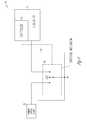
- FIG. 1illustrates an example power management system 10 .
- the power management system 10may include a generator 11 with a generator controller 12 , a transfer switch 13 having an output 14 and a switching mechanism 16 , and a primary power source 15 .
- the power management system 10may include fewer, more, or different components.
- the generator 11may include an internal combustion engine that drives an alternator to generate electrical energy.
- the generator 11may be configured to provide secondary power.
- the generator controller 12may operate the generator 11 , and may control when the generator 11 provides the secondary power.
- the generator 11may be connected with, and may provide secondary power to, a transfer switch 13 .
- the transfer switch 13may additionally be connected with a primary power source 15 .
- the primary power source 15may be configured to provide primary power to the transfer switch 13 .
- the transfer switch 13may include a switching mechanism 16 that may be moved to and between various positions.
- the switching mechanism 16may be positioned in a primary power position, during which primary power from the primary power source 15 may be delivered by the transfer switch 13 to an output 14 of the transfer switch 13 .
- the switching mechanism 16may be positioned in a secondary power position, during which secondary power from the generator 11 may be delivered by the transfer switch 13 to an output 14 of the transfer switch 13 .
- the switching mechanism 16may be positioned in an off position or a no power position, during which neither primary power from the primary power source 15 nor secondary power from the generator 11 may be delivered by the transfer switch 13 to an output 14 of the transfer switch 13 .
- the generator controller 12may be configured to control the transfer switch 13 and prohibit the transfer switch 13 from supplying primary power (e.g., from a primary power source 15 such as a utility) or secondary power from the generator 11 to an output 14 of the transfer switch 13 .
- primary powere.g., from a primary power source 15 such as a utility
- secondary powerfrom the generator 11 to an output 14 of the transfer switch 13 .
- the generator controller 12may be configured to operate a switching mechanism 16 in the transfer switch 13 .
- the generator controller 12may control the position of the switching mechanism 16 which determines whether the transfer switch 13 provides primary power or secondary power to the output 14 .
- the generator controller 12may position the switching mechanism 16 to prohibit the transfer switch 13 from supplying primary power, secondary power, or both to an output 14 of the transfer switch.
- the generator controller 12may control the position of the switching mechanism 16 by sending a signal to the switching mechanism 16 that controls the position of the switching mechanism 16 . It should be noted that any type of switching mechanism 16 that is known now or discovered in the future may be utilized in the transfer switch 13 .
- the generator controller 12may be configured to prevent the switching mechanism 16 from providing secondary power to the output 14 .
- the generator controller 12may set the position of the switching mechanism 16 to a primary power position or an off position when primary power is not available and secondary power is available.
- the generator controller 12may be configured to prohibit a designated transfer switch 13 from supplying secondary power to an output 14 of the transfer switch 13 by ignoring a start signal that is sent to the generator 11 from the transfer switch 13 . Since the generator 11 may not start as a result of the signal from the designated transfer switch 13 , the generator 11 may not provide secondary power to transfer switch 13 .
- FIG. 2shows an example power management system 20 .
- the switching mechanism 16may include a transfer coil 17 .
- the generator controller 12may be configured to control power to the transfer coil 17 .
- the generator controller 12may supply (or interrupt) power to the transfer coil 17 to move (or prevent from moving) the switching mechanism 16 between a primary power position, a secondary power position, and a no power position.
- the generator controller 12may thus control the transfer coil 17 to prevent the switching mechanism 13 from providing primary power or secondary power to the output 14 .
- Other systemsmay include a plurality of transfer coils in order to enable the transfer switch to supply primary power, a secondary power or no power. Some systems may include devices besides transfer coils to move (or prevent from moving) the switching mechanism 16 .
- FIG. 3shows an example power management system 30 , where the transfer switch 13 includes a transfer switch controller 18 .
- the transfer switch controller 18may control an operation of the transfer switch 13 , such as a position of the switching mechanism 16 .
- the generator controller 12may communicate with the transfer switch controller 18 , and may control the transfer switch 13 through the transfer switch controller 18 .
- the generator controller 12may provide a signal to the transfer switch controller 18 to prevent the switching mechanism 13 from providing primary (or secondary) power to the output 14 .
- the generator controller 12may provide a signal to another type of controller to prevent the switching mechanism 16 from providing primary power to the output 14 .
- the determination as to whether the generator controller 12 , the transfer switch controller 18 or another controller provides a signal to the switching mechanism 16may depend in part on the overall design, arrangement and components that are included in the power management system.
- FIG. 4illustrates the power management system 10 where the switching mechanism 16 is in an off position. In the off position, neither the primary power source 15 nor the generator 11 is connected to the output 14 .
- the physical design of the “off” position for the transfer switch 13may depend in part on the type of transfer switch 13 that is utilized in the power management system.
- the switching mechanism 16may be moved to the off position because a facility manager has determined that a user (e.g. a renter) of the primary and secondary power may not have paid fee to be eligible to receive the primary and secondary power.
- the facility managermay determine that a particular building (or room in a building) should not receive primary or secondary power.
- FIG. 5illustrates the power management system 10 where the switching mechanism 16 is in the secondary power position.
- the generator controller 12may override any other logic within the transfer switch 13 and force the switching mechanism 16 to the secondary power position. The generator controller 12 may thus prevent the switching mechanism 13 from providing primary power 15 to the output 14 by moving the switching mechanism 16 to the secondary power position.
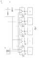
- FIG. 6illustrates an example power management system 60 where the generator controller 12 is connected with a plurality of transfer switches 13 A, 13 B, 13 C, 13 D, 13 E.
- the transfer switches 13 A, 13 B, 13 C, 13 D, 13 Emay include switching mechanisms 16 A, 16 B, 16 C, 16 D, 16 E and outputs 14 A, 14 B, 14 C, 14 D, 14 E connected with different loads L 1 , L 2 , L 3 , L 4 , L 5 .
- the generator 11 and generator controller 12may be connected with any number of transfer switches.
- the generator controller 12may control a position of one or more of the switching mechanisms 16 A, 16 B, 16 C, 16 D, 16 E of the transfer switches 13 A- 13 E.
- the generator controller 12may direct transfer switches 13 A, 13 B, 13 D to provide primary power 15 to loads L 1 , L 2 , L 4 and may direct transfer switches 13 C, 13 E to provide secondary power from generator 11 to loads L 3 , L 5 .
- the generator controller 12may control and position any of the switching mechanisms 16 A, 16 B, 16 C, 16 D, 16 E in any of the primary power position, the secondary power position, or the off position.
- the generator controller 12may, for example, prohibit each of the transfer switches 13 A, 13 B, 13 C, 13 D, 13 E from supplying primary or secondary power to an output 14 A, 14 B, 14 C, 14 D, 14 E of the respective transfer switches 13 A, 13 B, 13 C, 13 D, 13 E.
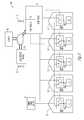
- FIG. 7illustrates an example power management system 70 where the transfer switches 13 A, 13 B, 13 C, 13 D, 13 E provide power to respective loads L 1 , L 2 , L 3 , L 4 , L 5 that are located within different rooms in a dwelling D.
- FIG. 8illustrates an example power management system 80 where the transfer switches 13 A, 13 B, 13 C, 13 D, 13 E provide power to respective loads L 1 , L 2 , L 3 , L 4 , L 5 that are located within different dwellings D 1 , D 2 , D 3 , D 4 , D 5 .
- the loads L 1 , L 2 , L 3 , L 4 , and L 5may be positioned in other rooms, buildings, dwellings, locations inside or outside, or any combination.
- the generator controller 12has directed transfer switches 13 A, 13 B, 13 D to provide primary power to loads L 1 , L 2 , L 4 and directed transfer switches 13 C, 13 E to provide secondary power to loads L 3 , L 5 .
- the generator controller 12may alternatively direct any of the transfer switches 13 A-E to provide any of the primary power, secondary power, or no power to the loads L 1 -L 5 , such as by controlling the position of the switching mechanisms 16 A, 16 B, 16 C, 16 D, 16 E of the transfer switches 13 A- 13 E.
- the generator controller 12may be controlled remotely, such as through a network I, by an electronic device 21 operated by a user U.
- the electronic device 21may send signals to the generator controller 12 to selectively control operation of at least some of the transfer switches 13 A, 13 B, 13 C, 13 D, 13 E.
- the generator controller 12may permit the user U to prohibit selected transfer switches 13 A, 13 B, 13 C, 13 D, 13 E from supplying primary or secondary power to the respective outputs 14 of the selected transfer switches 13 A, 13 B, 13 C, 13 D, 13 E.
- the generator controller 12may receive a signal from an electronic device 21 through the network I to prohibit the selected transfer switches 13 A, 13 B, 13 C, 13 D, 13 E from supplying primary or secondary power to the respective outputs 14 A, 14 B, 14 C, 14 D, 14 E of the selected transfer switches 13 A, 13 B, 13 C, 13 D, 13 E based on a location of the respective loads L 1 , L 2 , L 3 , L 4 , L 5 that are connected to the respective outputs 14 of the transfer switches 13 A, 13 B, 13 C, 13 D, 13 E.
- the generator controller 12may automatically selectively control operation of at least some of the transfer switches 13 A, 13 B, 13 C, 13 D, 13 E based on one or more parameters.
- the parameters by which the generator controller 12 selectively controls operation of the transfer switches 13 A, 13 B, 13 C, 13 D, 13 Emay depend in part on the application where the example power management systems are being utilized.
- FIGS. 7 and 8show where the user U may interact with the generator controller 12 via a display on the generator controller 12 or remotely via a network (e.g., the Internet I) which is connected to the generator controller 12 via server 20 .
- the user Uaccesses the server 20 with an electronic device 21 (e.g., computer, laptop, tablet, phone, etc.). It should be noted that portions of the network may be wired or wireless.
- a landlordmay elect to cut off primary and/or secondary power to a renter based on timely payment of rent that is due to the landlord.
- Another examplemay be that a landlord charges an extra fee for the availability of secondary power to a renter from a generator 11 when there is an interruption in primary power.
- the generator controller 12may automatically determine the position of any of the transfer switches 13 A, 13 B, 13 C, 13 D, 13 E based on a parameter. Parameters that the generator may monitor and use to determine a position of the transfer switches 13 A, 13 B, 13 C, 13 D, 13 E may include a date, season or time of year. For example, the generator controller 12 may automatically prohibit primary or secondary power to a respective output 14 A, 14 B, 14 C, 14 D, 14 E during winter season.
- Other example automatic parameters that the generator controller 12 may monitor and use to determine a position of the transfer switches 13 A, 13 B, 13 C, 13 D, 13 E, and/or automatically prohibit primary and/or secondary power to the respective outputs 14 A, 14 B, 14 C, 14 D, 14 Emay include temperature, ambient noise level, a received utility request, time of day, or weather conditions.
- FIG. 9illustrates an example embodiment of a method 900 of controlling a transfer switch. Part or all of the method 900 may be performed by the generator controller 12 or various other components. Part or all of the method 900 may be implemented as logic, which the generator controller 12 may execute.
- the method 900may include [ 901 ] determining whether power should (or should not) be applied to a load where the load is connected to a transfer switch 13 .
- the method 900may further include [ 902 ] using a generator controller 12 to prohibit the transfer switch 12 from providing primary or secondary power to the load.
- determining whether power should be applied to a loadmay include determining whether a user of the load has paid a fee to receive primary or secondary power (see, e.g., facility manager example described above).
- [ 902 ] using a generator controller 12 to prohibit the transfer switch 13 from providing primary or secondary power to the loadincludes using the generator controller 12 to move a switching mechanism 16 within the transfer switch 13 to (i) prevent providing secondary power to the load; (ii) an off position to prevent providing primary power and secondary power to the load; and/or (iii) prevent providing primary power to the load. It should be noted that the determination as whether to prevent primary and/or secondary power to the load, or move the transfer switch to an off position, may depend in part on the application where the power management system 10 is being utilized.
- determining whether power should be applied to a loadmay include determining whether power should be applied to a plurality of loads L 1 , L 2 , L 3 , L 4 , L 5 where at least some of the loads are connected to respective transfer switches 13 A, 13 B, 13 C, 13 D, 13 E.
- the method 900may further include using the generator controller 12 to prohibit particular transfer switches 13 A, 13 B, 13 C, 13 D, 13 E from providing primary power or secondary power to the loads L 1 , L 2 , L 3 , L 4 , L 5 that are connected to the respective transfer switches 13 A, 13 B, 13 C, 13 D, 13 E.
- FIG. 10is a flow diagram illustrating another example method 1000 of controlling a transfer switch 13 .
- the method 1000may be performed by the generator controller 12 or various other components.
- the method 1000may be implemented as logic, which the generator controller 12 may execute.
- the methodmay include [ 1001 ] detecting an interruption in primary power from a primary power source 15 , and [ 1002 ] gathering parameter information about a load, the load connected with the primary power source 15 and a generator 11 (see, e.g., automatic parameter information discussed above).
- Parameter informationmay be gathered by or using sensors, inputs, information stored in a server, events, or in various other ways.
- the parameter informationmay include information about the load, a power-consuming device connected with the load, or a user of the load.
- the method [ 1000 ]may include [ 1003 ] determining whether the load can receive generator power from the generator 11 based on the parameter information.
- the controller 12may compare the parameter information to one or more thresholds or input the parameter information into one or more decision algorithms or trees, from which the controller 12 may determine whether or not the load can receive power from the generator 11 .
- the controller 12may gather parameter information may include information that the user of the load is not allowed to receive secondary power, and may thus conclude that no generator power may be supplied to the load based on the received parameter information. Other examples are possible.
- the method [ 1000 ]may include [ 1004 ] prohibiting the load from receiving the generator power when the interruption is detected and the determination indicates that the load cannot receive the generator power. Additionally or alternatively, the method [ 1000 ] may include or [ 1005 ] allowing the load to receive generator power when the interruption is detected and the determination indicates that the load can receive the generator power.
- prohibiting the load from receiving the generator powermay include ignoring signals from a transfer switch 13 that indicates when primary power has been interrupted where the transfer switch 13 is connected to the load.
- the parameter informationmay include information about whether the load was eligible to receive the primary power immediately prior to the interruption such that the load cannot receive generator power from the generator when the parameter information indicates that the load was not eligible to receive the primary power immediately prior to the interruption.
- the method [ 1000 ]may include fewer, more, or different blocks. Additionally or alternatively, one or more blocks of the method may be performed in a different order or simultaneously. Other variations are possible.
- FIG. 11is a flow diagram illustrating another example method 1100 of controlling a transfer switch 13 .
- the method 1100may be performed by the controller 12 or various other components.
- the method 1100may be implemented as logic, which the controller 12 may execute.
- the methodmay include [ 1101 ] operating a transfer switch 13 in a normal manner, and [ 1102 ] gathering parameter information and/or user inputs about a load, the load connected with the primary power source 15 and a generator 11 .
- the method [ 1100 ]may further include [ 1103 ] determining whether to interrupt normal transfer switch 13 operation based on the parameter information or user inputs.
- the methodmay include [ 1004 ] overriding normal transfer switch 13 operation when the parameter information or user inputs indicate that the normal transfer switch 13 operation should be interrupted. For example, where the normal transfer switch 13 operation would require the switching mechanism 16 to switch from a primary power position to a secondary power position, and where the parameter information indicates that the user of the load should not receive secondary power, the controller 12 may override the transfer switch 13 operation and control the switching mechanism 16 to stay in the primary power position or move the switching mechanism 16 to an off position. Other variations are possible. If, instead, the normal transfer switch 13 operation should not be interrupted, the method may return to block 1102 , and the parameter information and/or user inputs may continue to be gathered. In some variations, the method [ 1100 ] may include fewer, more, or different blocks. Additionally or alternatively, one or more blocks of the method [ 1100 ] may be performed in a different order or simultaneously. Other variations are possible.
- the example power management systems and methods described hereininclude a generator controller 12 that is configured to prohibit a transfer switch 13 from supplying primary and/or secondary power to an output 14 of the transfer switch 13 . Therefore, the power management systems and methods may provide flexibility in establishing what types of power (i.e., primary, secondary or neither) are provided to a load that is connected to the transfer switch 13 .
- the example power management systems and methods described hereinmay include a generator controller 12 that is configured to prohibit multiple transfer switches 13 A, 13 B, 13 C, 13 D, 13 E from supplying primary and/or secondary power to respective outputs 14 of the transfer switches 13 A, 13 B, 13 C, 13 D, 13 E. Therefore, the generator controller 12 is able to establish what type of power (i.e., primary, secondary or neither) is provided to the respective loads L 1 , L 2 , L 3 , L 4 , L 5 that are connected to the outputs 14 of each of the transfer switches 13 A, 13 B, 13 C, 13 D, 13 E.
- a generator controller 12that is configured to prohibit multiple transfer switches 13 A, 13 B, 13 C, 13 D, 13 E from supplying primary and/or secondary power to respective outputs 14 of the transfer switches 13 A, 13 B, 13 C, 13 D, 13 E. Therefore, the generator controller 12 is able to establish what type of power (i.e., primary, secondary or neither) is provided to the respective loads L 1 , L 2
Landscapes
- Engineering & Computer Science (AREA)
- Power Engineering (AREA)
- Business, Economics & Management (AREA)
- Emergency Management (AREA)
- Theoretical Computer Science (AREA)
- Physics & Mathematics (AREA)
- General Engineering & Computer Science (AREA)
- General Physics & Mathematics (AREA)
- Stand-By Power Supply Arrangements (AREA)
Abstract
Description
Claims (20)
Priority Applications (1)
| Application Number | Priority Date | Filing Date | Title |
|---|---|---|---|
| US13/736,998US9281716B2 (en) | 2011-12-20 | 2013-01-09 | Generator controller configured for preventing automatic transfer switch from supplying power to the selected load |
Applications Claiming Priority (3)
| Application Number | Priority Date | Filing Date | Title |
|---|---|---|---|
| US201161577816P | 2011-12-20 | 2011-12-20 | |
| US13/664,677US9841799B2 (en) | 2011-12-20 | 2012-10-31 | System and method for using a network to control a power management system |
| US13/736,998US9281716B2 (en) | 2011-12-20 | 2013-01-09 | Generator controller configured for preventing automatic transfer switch from supplying power to the selected load |
Related Parent Applications (1)
| Application Number | Title | Priority Date | Filing Date |
|---|---|---|---|
| US13/664,677Continuation-In-PartUS9841799B2 (en) | 2011-12-20 | 2012-10-31 | System and method for using a network to control a power management system |
Publications (2)
| Publication Number | Publication Date |
|---|---|
| US20130154370A1 US20130154370A1 (en) | 2013-06-20 |
| US9281716B2true US9281716B2 (en) | 2016-03-08 |
Family
ID=48609397
Family Applications (1)
| Application Number | Title | Priority Date | Filing Date |
|---|---|---|---|
| US13/736,998Active2033-10-23US9281716B2 (en) | 2011-12-20 | 2013-01-09 | Generator controller configured for preventing automatic transfer switch from supplying power to the selected load |
Country Status (1)
| Country | Link |
|---|---|
| US (1) | US9281716B2 (en) |
Cited By (3)
| Publication number | Priority date | Publication date | Assignee | Title |
|---|---|---|---|---|
| US20160226227A1 (en)* | 2015-01-30 | 2016-08-04 | Dongguan Vanke Building Technique Research Co., Ltd | Heavy-current system and heavy-current distributor used in building |
| US9841799B2 (en) | 2011-12-20 | 2017-12-12 | Kohler Co. | System and method for using a network to control a power management system |
| US10424924B2 (en)* | 2016-05-19 | 2019-09-24 | Consolidated Edison Company Of New York, Inc. | Utility grid generator connection |
Families Citing this family (2)
| Publication number | Priority date | Publication date | Assignee | Title |
|---|---|---|---|---|
| US9727515B2 (en) | 2014-02-19 | 2017-08-08 | Cyber Switching Patents, Llc | Cabinet level controller with asset management |
| US11509165B2 (en)* | 2017-08-24 | 2022-11-22 | Myers Emergency Power Systems Llc | Automatic transfer switch for lighting loads with integral load shedding by dimming control |
Citations (178)
| Publication number | Priority date | Publication date | Assignee | Title |
|---|---|---|---|---|
| US4031406A (en) | 1975-06-16 | 1977-06-21 | Pacific Technology, Inc. | Method and apparatus for controlling electrical loads |
| US4034233A (en) | 1976-07-22 | 1977-07-05 | Pacific Technology | Power monitoring and regulating circuit and method having an analog input representing power rate and a digital output for controlling the on/off states of a plurality of loads |
| US4064485A (en) | 1976-07-22 | 1977-12-20 | Pacific Technology, Inc. | Digital load control circuit and method for power monitoring and limiting system |
| US4099067A (en) | 1975-08-25 | 1978-07-04 | Caterpillar Tractor Co. | Load-shedding control for diesel-electric sets |
| US4639657A (en) | 1984-08-30 | 1987-01-27 | Basler Electric Company | Electrical control apparatus and methods |
| US4701690A (en) | 1985-11-27 | 1987-10-20 | Basler Electric Company | Transfer apparatus, regulating apparatus and methods |
| US4731547A (en) | 1986-12-12 | 1988-03-15 | Caterpillar Inc. | Peak power shaving apparatus and method |
| US4800291A (en) | 1987-03-04 | 1989-01-24 | Basler Electric Company | Electronic circuit for control of a voltage regulator of an electrical generator |
| US4982149A (en)* | 1989-01-11 | 1991-01-01 | Kabushiki Kaisha Toshiba | Electric supply apparatus having means for correcting supply voltage fluctuations |
| US5294879A (en) | 1991-11-01 | 1994-03-15 | Basler Electric Company | Microprocessor-controlled regulator |
| US5414640A (en) | 1991-07-05 | 1995-05-09 | Johnson Service Company | Method and apparatus for adaptive demand limiting electric consumption through load shedding |
| US5422517A (en) | 1993-05-26 | 1995-06-06 | United Technologies Corporation | Control of electric loads during generator failure in a multi-generator system |
| US5604421A (en) | 1994-06-18 | 1997-02-18 | Smiths Industries Public Limited Company | Electrical systems |
| US5640060A (en) | 1995-02-09 | 1997-06-17 | Basler Electric Company | Apparatus for synchronizing frequency and phase of two voltage sources |
| US5684710A (en) | 1995-01-05 | 1997-11-04 | Tecom Inc. | System for measuring electrical power interruptions |
| US5761073A (en) | 1995-02-09 | 1998-06-02 | Basler Electric Company | Programmable apparatus for synchronizing frequency and phase of two voltage sources |
| US5861683A (en) | 1997-05-30 | 1999-01-19 | Eaton Corporation | Panelboard for controlling and monitoring power or energy |
| US5880537A (en) | 1997-01-10 | 1999-03-09 | Caterpillar Inc. | Uninterruptable power supply |
| US6067482A (en)* | 1999-01-08 | 2000-05-23 | Hussmann Corporation | Load shifting control system for commercial refrigeration |
| US6104171A (en) | 1998-11-23 | 2000-08-15 | Caterpillar Inc. | Generator set with redundant bus sensing and automatic generator on-line control |
| US6107927A (en) | 1998-12-10 | 2000-08-22 | Caterpillar Inc. | Generator set controller with integral synchroscope mode |
| US6114775A (en)* | 1997-10-27 | 2000-09-05 | Mando Machinery Corporation | Control system of auxiliary power system for a hybrid electric vehicle |
| US6163088A (en) | 1999-09-30 | 2000-12-19 | Caterpillar Inc. | Method and apparatus for providing standby power from a generator using capacitor supplied voltage |
| US6172432B1 (en)* | 1999-06-18 | 2001-01-09 | Gen-Tran Corporation | Automatic transfer switch |
| US6191500B1 (en) | 1998-11-06 | 2001-02-20 | Kling Lindquist Partnership, Inc. | System and method for providing an uninterruptible power supply to a critical load |
| US20010005894A1 (en) | 1999-12-27 | 2001-06-28 | Masahiro Fukui | Remote power management system of information processing apparatus or the like |
| US20020033020A1 (en)* | 2000-09-21 | 2002-03-21 | Yoshifumi Tonomura | Solar power generation administration system, and solar power generation administration method to provide useful information to user |
| US6362985B1 (en) | 1999-05-27 | 2002-03-26 | Ntt Data Corporation | Power transmission apparatus and method for power transmission |
| US20020079741A1 (en) | 2000-12-22 | 2002-06-27 | Anderson William J. | Automatic transfer switch and engine control |
| US20020111905A1 (en)* | 2001-02-13 | 2002-08-15 | Naoyuki Nagafuchi | Power demand and supply-adjustment system and method |
| US20030023888A1 (en)* | 2001-07-30 | 2003-01-30 | Smith Robert B. | Loadshedding uninterruptible power supply |
| US6531790B2 (en) | 2000-08-01 | 2003-03-11 | Advanced Controls, Inc. | Generator transfer switching system with multiple generator modes |
| US6552888B2 (en) | 2001-01-22 | 2003-04-22 | Pedro J. Weinberger | Safety electrical outlet with logic control circuit |
| US20030075982A1 (en) | 2000-04-11 | 2003-04-24 | Seefeldt William J. | Transfer switch |
| US20030107349A1 (en) | 2000-01-28 | 2003-06-12 | Lawrence Haydock | Ac power generating system |
| US20030157928A1 (en)* | 2002-02-21 | 2003-08-21 | Phillips Marc S. | Systems, methods, and apparatus for efficient transfer of information over wireless data links |
| US6631310B1 (en) | 2000-09-15 | 2003-10-07 | General Electric Company | Wireless engine-generator systems digital assistant |
| US6653821B2 (en) | 2001-06-15 | 2003-11-25 | Generac Power Systems, Inc. | System controller and method for monitoring and controlling a plurality of generator sets |
| US6657416B2 (en) | 2001-06-15 | 2003-12-02 | Generac Power Systems, Inc. | Control system for stand-by electrical generator |
| US6668629B1 (en) | 1999-11-26 | 2003-12-30 | General Electric Company | Methods and apparatus for web-enabled engine-generator systems |
| US6686547B2 (en) | 1999-08-19 | 2004-02-03 | Generac Power Systems, Inc. | Relay for a transfer mechanism which transfers power between a utility source and a stand-by generator |
| US6691065B2 (en) | 2001-02-27 | 2004-02-10 | Hitachi, Ltd. | System foraiding the preparation of operation and maintenance plans for a power generation installation |
| US20040051515A1 (en) | 2002-09-13 | 2004-03-18 | Hiroshi Ikekame | Current measurement technique and current measurement apparatus |
| US20040052044A1 (en)* | 2002-09-17 | 2004-03-18 | Brother Kogyo Kabushiki Kaisha | Foldable display, input device provided with the display and foldable keyboard, and personal computer provided with the input device |
| US20040075343A1 (en) | 2002-09-05 | 2004-04-22 | Paul Wareham | System and method for power load management |
| US20040095237A1 (en)* | 1999-01-09 | 2004-05-20 | Chen Kimball C. | Electronic message delivery system utilizable in the monitoring and control of remote equipment and method of same |
| US6739145B2 (en) | 2000-05-04 | 2004-05-25 | Vasu Tech Limited | Configurable electronic controller |
| US6747368B2 (en) | 2001-08-30 | 2004-06-08 | Harold M. Jarrett, Jr. | Wireless control of power transfer switches for electrical load management |
| US6791208B2 (en) | 2002-12-27 | 2004-09-14 | Mark Pfeiffer | Electrical power controller |
| US6798187B1 (en) | 2001-09-26 | 2004-09-28 | Reliance Controls Corporation | Generator status information display for power transfer switch |
| US20040199297A1 (en)* | 2003-02-27 | 2004-10-07 | Schaper Scott R. | Generator controller |
| US6825578B2 (en) | 2001-01-24 | 2004-11-30 | Joseph Perttu | State machine controlled automatic transfer switch system |
| US20040243525A1 (en)* | 2003-05-07 | 2004-12-02 | Brian Forrester | System and method for disconnecting utility services |
| US20050024905A1 (en)* | 2003-07-29 | 2005-02-03 | Sanyo Electric Co., Ltd. | Uninterruptible power supply device |
| US20050059373A1 (en) | 2003-08-28 | 2005-03-17 | Takahiro Nakamura | Frequency generator and communication system using the same |
| US20050063117A1 (en) | 2002-12-06 | 2005-03-24 | Hitachi, Ltd. | Power supply system |
| US6876103B2 (en) | 2000-12-29 | 2005-04-05 | General Electric Company | Automatic transfer switch systems and controllers |
| US20050072220A1 (en) | 2001-02-19 | 2005-04-07 | Rosemount Analytical Inc. | Generator monitoring, control and efficiency |
| US6882904B1 (en) | 2000-12-29 | 2005-04-19 | Abb Technology Ag | Communication and control network for distributed power resource units |
| US20050099131A1 (en)* | 2001-08-10 | 2005-05-12 | Amarillas Sal G. | Electrical power conservation apparatus and method |
| US20050105399A1 (en) | 2001-04-13 | 2005-05-19 | Strumpf David M. | Appliance having a clock set to universal time |
| US20050116814A1 (en) | 2003-10-24 | 2005-06-02 | Rodgers Barry N. | Intelligent power management control system |
| US20050125519A1 (en) | 2003-11-26 | 2005-06-09 | Allen Yang | Remote network management system |
| US20050128659A1 (en) | 2002-02-14 | 2005-06-16 | Shinji Hibi | Power source switching unit and power source management system comprising it |
| US20050141154A1 (en) | 2003-12-03 | 2005-06-30 | Atwood Industries, Inc. | Power averaging and power load management system |
| US20050216131A1 (en) | 2004-03-24 | 2005-09-29 | Sodemann Wesley C | Residential load power management system |
| US20050268164A1 (en)* | 2004-05-11 | 2005-12-01 | Kentaroh Hara | Power supplying method and apparatus and a system using the same |
| US20060022950A1 (en)* | 2004-07-09 | 2006-02-02 | Qualcomm Incorporated | Multi-function portable electronic device |
| US20060028069A1 (en) | 2004-08-09 | 2006-02-09 | Loucks David G | Retrofit kit for converting a transfer switch to a switch for soft-load transfer, and soft-load power distribution system and method |
| US7015599B2 (en) | 2003-06-27 | 2006-03-21 | Briggs & Stratton Power Products Group, Llc | Backup power management system and method of operating the same |
| US7053497B2 (en) | 2003-02-10 | 2006-05-30 | Briggs & Stratton Power Products Group, Llc | Monitoring system for a generator |
| US20060129798A1 (en) | 2004-11-30 | 2006-06-15 | Allied Generators, Inc. | Stand-by power generator monitoring system |
| US20060146488A1 (en)* | 2005-01-05 | 2006-07-06 | Nokia Corporation | Foldable electronic device and a flexible display device |
| US20060187600A1 (en) | 2005-02-22 | 2006-08-24 | Brown Scott R | Independent automatic shedding branch circuit breaker |
| US20060203814A1 (en) | 2005-03-11 | 2006-09-14 | On-Bright Electronics (Shanghai) Co., Ltd. | System and method for adaptive switching frequency control |
| US7119457B1 (en) | 2003-02-11 | 2006-10-10 | Reliance Controls Corporation | Prioritized actuation system with overload protection for a generator transfer switch |
| US7133787B2 (en) | 2003-02-26 | 2006-11-07 | Sharp Kabushiki Kaisha | Method of managing electric power generator, managing device, electric power generator, communications device, computer program therefor, and managing system for electric power generator |
| US7149605B2 (en) | 2003-06-13 | 2006-12-12 | Battelle Memorial Institute | Electrical power distribution control methods, electrical energy demand monitoring methods, and power management devices |
| US20060284843A1 (en) | 2003-08-05 | 2006-12-21 | Kokusan Denki Co., Tld. | Inverter controlled generator set |
| US7177728B2 (en) | 2003-12-30 | 2007-02-13 | Jay Warren Gardner | System and methods for maintaining power usage within a set allocation |
| US7208850B2 (en) | 2003-09-02 | 2007-04-24 | Generac Power Systems, Inc. | Power strip transfer mechanism |
| US20070094131A1 (en)* | 2005-10-26 | 2007-04-26 | Communications Product Development, Inc. | Bad debt recovery system and method in a prepaid services environment |
| US7218998B1 (en) | 2005-07-11 | 2007-05-15 | Neale Stephen D | System and method for limiting power demand in an energy delivery system |
| US20070120538A1 (en) | 2003-12-03 | 2007-05-31 | Keihin Corporation | Cooperative control apparatus |
| US20070129851A1 (en) | 2005-09-07 | 2007-06-07 | Rossi John F | Method and System for Local Load Control |
| US7230345B2 (en) | 2005-01-12 | 2007-06-12 | Generac Power Systems, Inc. | Method for exercising a stand-by electrical generator |
| US7239045B2 (en) | 2003-12-19 | 2007-07-03 | Eaton Corporation | Power distribution system and control system for same |
| US20070222295A1 (en) | 2002-09-05 | 2007-09-27 | Paul Wareham | System and method for power load management |
| US20070222294A1 (en) | 2004-04-09 | 2007-09-27 | Jirou Tsukida | Underfrequency Load Shedding Protection System |
| US20070241739A1 (en)* | 2004-07-05 | 2007-10-18 | Yasuhiro Uenou | Power Consumption Measuring Device and Power Control System |
| US20070266423A1 (en) | 2003-09-29 | 2007-11-15 | Tehee Stanley W Jr | Various methods and apparatuses to provide remote access to a wind turbine generator system |
| US7336003B2 (en) | 2005-04-05 | 2008-02-26 | Eaton Corporation | Transfer switch and power system including the same |
| US7345456B2 (en) | 2005-01-24 | 2008-03-18 | Basler Electric Company | Power system stabilizer providing excitation limiter functions |
| US7356384B2 (en) | 2004-07-15 | 2008-04-08 | Briggs & Stratton Corporation | Load management system |
| US20080086394A1 (en)* | 2006-06-29 | 2008-04-10 | Carina Technology, Inc. | System and method for controlling a utility meter |
| US20080091626A1 (en)* | 2006-10-17 | 2008-04-17 | Gary Kremen | Systems, methods and financial instruments for renewable energy consumer premises equipment financing |
| US7362696B2 (en) | 2002-10-21 | 2008-04-22 | General Electric Company | Method and apparatus for automatic transfer switch |
| US20080150360A1 (en) | 2006-12-20 | 2008-06-26 | Nortel Networks Limited | System and Method for Providing Power Management in a Sensor Network |
| US20080157593A1 (en) | 2006-12-29 | 2008-07-03 | Cummins Power Generation Ip, Inc. | Management of an electric power generation and storage system |
| US20080157600A1 (en) | 2006-12-29 | 2008-07-03 | Cummins Power Generation Ip, Inc. | Operator interface for an electric power generation system |
| US20080179958A1 (en)* | 2007-01-26 | 2008-07-31 | Eaton Corporation | Automatic Transfer Switch With Monitor Mode and Method Employing the Same |
| US20080211455A1 (en)* | 2005-07-30 | 2008-09-04 | Dong-Young Park | Rechargeable Power Supply, Battery Device, Contactless Charger System And Method For Charging Rechargeable Battery Cell |
| US7460931B2 (en) | 2005-10-07 | 2008-12-02 | Jay Jacobson | Method and system for improving the efficiency and reliability of a power grid |
| US20080313006A1 (en) | 2006-08-24 | 2008-12-18 | Blue Pillar, Inc. | Systems, methods, and devices for managing emergency power supply systems |
| US7489988B2 (en)* | 2003-11-19 | 2009-02-10 | Panasonic Corporation | Generator control system, generating apparatus control method, program and record medium |
| US7521822B2 (en) | 2007-05-07 | 2009-04-21 | Cummins Power Generation Ip, Inc. | Protection techniques for a back-up electric power system |
| US20090108678A1 (en) | 2007-10-31 | 2009-04-30 | Caterpillar Inc. | Power system with method for adding multiple generator sets |
| US20090113874A1 (en) | 2007-11-02 | 2009-05-07 | Caterpillar Inc. | System and method for electrically regenerating a particulate filter assembly of a generator set |
| US20090152951A1 (en) | 2007-12-18 | 2009-06-18 | Caterpillar Inc. | Electric system for providing uninterruptible power |
| US7557544B2 (en) | 2007-04-23 | 2009-07-07 | Cummins Power Generation Ip, Inc. | Zero crossing detection for an electric power generation system |
| US20090179498A1 (en) | 2008-01-14 | 2009-07-16 | Lathrop Todd M | Transfer switch controller providing an alternating current voltage to a generator and transfer switch including the same |
| US20090198386A1 (en) | 2008-01-31 | 2009-08-06 | Basler Electric Company | Digital Excitation Control System Utilizing Swarm Intelligence and An Associated Method of Use |
| US20090195224A1 (en) | 2008-01-31 | 2009-08-06 | Basler Electric Company | Digital Excitation Control System Utilizing Self-Tuning PID Gains and an Associated Method of Use |
| US7573145B2 (en) | 2006-11-16 | 2009-08-11 | Cummins Power Generation Ip, Inc. | Electric power generation system controlled to reduce perception of operational changes |
| US7579712B2 (en) | 2004-03-16 | 2009-08-25 | The Tokyo Electric Power Company | Power system protection system |
| US20090216386A1 (en) | 2008-02-26 | 2009-08-27 | Wedel Francis X | Load shed transfer mechanism and method |
| US7582986B2 (en) | 2004-10-08 | 2009-09-01 | Schweitzer Engineering Laboratories, Inc. | Compensated inverse-time undervoltage load shedding systems |
| US20090240377A1 (en) | 2007-09-19 | 2009-09-24 | Briggs And Stratton Corporation | Power monitoring system |
| US7598623B2 (en) | 2006-12-29 | 2009-10-06 | Cummins Power Generation Ip, Inc. | Distinguishing between different transient conditions for an electric power generation system |
| US7608948B2 (en) | 2006-06-20 | 2009-10-27 | Lutron Electronics Co., Inc. | Touch screen with sensory feedback |
| US7619324B2 (en) | 2007-01-29 | 2009-11-17 | Caterpillar Inc. | Power system with multiple generator sets |
| US20090290270A1 (en) | 2008-05-21 | 2009-11-26 | Honeywell International Inc. | Overload control of an electric power generation system with unknown availability of mechanical power capacity |
| US20100007313A1 (en) | 2007-02-06 | 2010-01-14 | Cummins Generator Technologies Limited | Method and apparatus for controlling excitation |
| US20100019574A1 (en)* | 2008-07-24 | 2010-01-28 | John Baldassarre | Energy management system for auxiliary power source |
| US7656060B2 (en) | 2007-10-31 | 2010-02-02 | Caterpillar Inc. | Power system with method for adding multiple generator sets |
| US20100039077A1 (en) | 2007-02-19 | 2010-02-18 | Cummins Generator Technologies Limited | Load angle measurement and pole slip detection |
| US20100038966A1 (en) | 2008-07-30 | 2010-02-18 | Gen-Tran Corporation | Automatic transfer switch |
| US20100066551A1 (en) | 2008-09-15 | 2010-03-18 | Caterpillar Inc. | Method and apparatus for power generation failure diagnostics |
| US20100094475A1 (en) | 2007-10-14 | 2010-04-15 | Gilbert Masters | Electrical Energy Usage Monitoring System |
| US20100102637A1 (en) | 2008-10-24 | 2010-04-29 | Caterpillar Inc. | Generator set control system |
| US20100109344A1 (en) | 2008-10-30 | 2010-05-06 | Caterpillar Inc. | Power system having transient control |
| US20100114394A1 (en)* | 2004-11-09 | 2010-05-06 | Denso Corporation | Dual type vehicle power-supply apparatus |
| US7715951B2 (en) | 2007-08-28 | 2010-05-11 | Consert, Inc. | System and method for managing consumption of power supplied by an electric utility |
| US20100148588A1 (en) | 2008-12-12 | 2010-06-17 | Caterpillar Inc. | Genset control system implementing engine synchronization |
| US20100156191A1 (en) | 2008-12-18 | 2010-06-24 | Caterpillar Inc. | Generator set control system |
| US20100156117A1 (en) | 2008-12-19 | 2010-06-24 | Caterpillar Inc. | Genset power system having multiple modes of operation |
| US7747355B2 (en) | 2006-11-07 | 2010-06-29 | Potenco, Inc. | Electrical power generator with adaptive coupling |
| US20100179893A1 (en)* | 2009-01-14 | 2010-07-15 | Tonya Marie Burke | System for controlling the charge rate of an electric vehicle battery by a third party, and monitoring, recording, and reporting the power supplied to it. |
| US20100181177A1 (en)* | 2009-01-02 | 2010-07-22 | Young Gordon W | Simple emergency power connection switch |
| US7786616B2 (en) | 2003-02-07 | 2010-08-31 | Cummins Power Generation Inc. | Generator with DC boost and split bus bidirectional DC-to-DC converter for uninterruptible power supply system or for enhanced load pickup |
| US20100225167A1 (en) | 2009-03-06 | 2010-09-09 | Briggs And Stratton Corporation | Power management system and method of operating the same |
| US20100253140A1 (en)* | 2007-11-28 | 2010-10-07 | Toyota Jidosha Kabushiki Kaisha | Power supply controller |
| US20100288326A1 (en)* | 2009-05-18 | 2010-11-18 | Jon Murray Schroeder | Solar home electrification with grid connection |
| US7855871B2 (en) | 2008-03-26 | 2010-12-21 | Siemens Industry, Inc. | Generator ready load center |
| US20110017717A1 (en)* | 2009-07-24 | 2011-01-27 | Lincoln Global, Inc. | Engine driven welding power supplies with two piece shaft |
| WO2011027195A1 (en) | 2009-09-07 | 2011-03-10 | Abb Technology Ltd | Method and system for power management |
| US20110068631A1 (en) | 2008-06-10 | 2011-03-24 | Rolls-Royce Plc | Electrical generator network and a local electrical system |
| US20110109291A1 (en) | 2009-11-11 | 2011-05-12 | Richtek Technology Corp. | Frequency control circuit and method for a non-constant frequency voltage regulator |
| US7948117B2 (en) | 2008-07-21 | 2011-05-24 | Eaton Corporation | Transfer switch controller employing active inductive load control and transfer switch including the same |
| US20110148360A1 (en)* | 2009-12-23 | 2011-06-23 | Eun-Ra Lee | Energy storage system and method of controlling the same |
| US20110173470A1 (en)* | 2010-01-14 | 2011-07-14 | Bao Tran | Minimizing power consumption in computers |
| US20110175450A1 (en)* | 2010-01-18 | 2011-07-21 | David Vicari | Load Control Module For A Generator And Method Of Operation |
| US20110175742A1 (en)* | 2010-01-20 | 2011-07-21 | Lg Electronics Inc. | Refrigerator and control method thereof |
| WO2011085477A1 (en) | 2010-01-13 | 2011-07-21 | Enbala Power Networks Inc. | Ancillary services network apparatus |
| US8009039B2 (en) | 2008-09-18 | 2011-08-30 | Sensormatic Electronics, LLC | EAS power management system |
| US8027180B2 (en) | 2007-10-19 | 2011-09-27 | Kokusan Denki Co., Ltd. | Power generating apparatus |
| US8065050B2 (en) | 2008-04-25 | 2011-11-22 | GM Global Technology Operations LLC | Method and apparatus for detecting an insufficient phase current in a permanent magnet synchronous motor |
| US20110296169A1 (en)* | 2008-09-05 | 2011-12-01 | Charles Graham Palmer | Facilitating secure communication between utility devices |
| US20110291483A1 (en)* | 2010-05-31 | 2011-12-01 | Shimizu Corporation | Electric power system |
| US20110291411A1 (en) | 2010-06-01 | 2011-12-01 | Keith Ronald Folken | Power distribution system having priority load control |
| US20110298286A1 (en) | 2010-06-03 | 2011-12-08 | Briggs & Stratton Corporation | Dynamic load shedding system for a standby generator |
| US20110298285A1 (en) | 2010-06-03 | 2011-12-08 | Briggs & Stratton Corporation | Active load management system |
| US20120090966A1 (en) | 2010-10-18 | 2012-04-19 | Eaton Corporation | Automatic transfer switch with transfer inhibitor |
| US8169755B2 (en) | 2009-05-15 | 2012-05-01 | Mitsubishi Electric Corp. | Power supply system |
| US8205594B2 (en) | 2008-10-29 | 2012-06-26 | Caterpillar Inc. | Genset control system having predictive load management |
| US20120179547A1 (en) | 2011-01-06 | 2012-07-12 | General Electric Company | Added features of hem/heg using gps technology |
| US20120217315A1 (en) | 2011-02-24 | 2012-08-30 | Dane Camden Witbeck | System for controlling temperatures of multiple zones in multiple structures |
| US20120242451A1 (en) | 2011-03-25 | 2012-09-27 | Yasuyuki Tanaka | Generator system monitoring apparatus and computer readable medium |
| US20120256483A1 (en) | 2009-12-17 | 2012-10-11 | Sanyo Electric Co., Ltd. | Electrical charge and discharge system, method of managing a battery and a power generator, and computer-readable recording medium |
| US20130018843A1 (en) | 2011-07-14 | 2013-01-17 | Robert Marten Bultman | Storing data following a power outage and without a proper time source |
| US20130079943A1 (en) | 2011-09-28 | 2013-03-28 | Ii Thomas Francis Darden | Systems and methods for microgrid power generation management with selective disconnect |
| US8417391B1 (en) | 2011-12-15 | 2013-04-09 | Restore Nv | Automated demand response energy management system |
| US20130106190A1 (en)* | 2011-11-01 | 2013-05-02 | Hung-Chieh Lin | Power supply system with automatic transfer function and method of controlling the same |
| US20130147412A1 (en)* | 2011-12-09 | 2013-06-13 | The Boeing Company | Power System Protection |
| US20130158726A1 (en) | 2011-12-20 | 2013-06-20 | Kohler Co. | System and method for using a network to control multiple power management systems |
| US20140001873A1 (en) | 2011-03-15 | 2014-01-02 | Loncin Motor Co., Ltd. | Method and device for controlling internal combustion engine driven generator set to run in parallel |
| US8736090B2 (en)* | 2009-08-12 | 2014-05-27 | Wartsila Finland Oy | Protection arrangement of an electric power system |
| US8942854B2 (en)* | 2011-11-28 | 2015-01-27 | Kohler Co. | System and method for identifying electrical devices in a power management system |
- 2013
- 2013-01-09USUS13/736,998patent/US9281716B2/enactiveActive
Patent Citations (200)
| Publication number | Priority date | Publication date | Assignee | Title |
|---|---|---|---|---|
| US4031406A (en) | 1975-06-16 | 1977-06-21 | Pacific Technology, Inc. | Method and apparatus for controlling electrical loads |
| US4099067A (en) | 1975-08-25 | 1978-07-04 | Caterpillar Tractor Co. | Load-shedding control for diesel-electric sets |
| US4034233A (en) | 1976-07-22 | 1977-07-05 | Pacific Technology | Power monitoring and regulating circuit and method having an analog input representing power rate and a digital output for controlling the on/off states of a plurality of loads |
| US4064485A (en) | 1976-07-22 | 1977-12-20 | Pacific Technology, Inc. | Digital load control circuit and method for power monitoring and limiting system |
| US4639657A (en) | 1984-08-30 | 1987-01-27 | Basler Electric Company | Electrical control apparatus and methods |
| US4701690A (en) | 1985-11-27 | 1987-10-20 | Basler Electric Company | Transfer apparatus, regulating apparatus and methods |
| US4731547A (en) | 1986-12-12 | 1988-03-15 | Caterpillar Inc. | Peak power shaving apparatus and method |
| US4800291A (en) | 1987-03-04 | 1989-01-24 | Basler Electric Company | Electronic circuit for control of a voltage regulator of an electrical generator |
| US4982149A (en)* | 1989-01-11 | 1991-01-01 | Kabushiki Kaisha Toshiba | Electric supply apparatus having means for correcting supply voltage fluctuations |
| US5414640A (en) | 1991-07-05 | 1995-05-09 | Johnson Service Company | Method and apparatus for adaptive demand limiting electric consumption through load shedding |
| US5294879A (en) | 1991-11-01 | 1994-03-15 | Basler Electric Company | Microprocessor-controlled regulator |
| US5422517A (en) | 1993-05-26 | 1995-06-06 | United Technologies Corporation | Control of electric loads during generator failure in a multi-generator system |
| US5604421A (en) | 1994-06-18 | 1997-02-18 | Smiths Industries Public Limited Company | Electrical systems |
| US5684710A (en) | 1995-01-05 | 1997-11-04 | Tecom Inc. | System for measuring electrical power interruptions |
| US5640060A (en) | 1995-02-09 | 1997-06-17 | Basler Electric Company | Apparatus for synchronizing frequency and phase of two voltage sources |
| US5761073A (en) | 1995-02-09 | 1998-06-02 | Basler Electric Company | Programmable apparatus for synchronizing frequency and phase of two voltage sources |
| US5880537A (en) | 1997-01-10 | 1999-03-09 | Caterpillar Inc. | Uninterruptable power supply |
| US5861683A (en) | 1997-05-30 | 1999-01-19 | Eaton Corporation | Panelboard for controlling and monitoring power or energy |
| US6114775A (en)* | 1997-10-27 | 2000-09-05 | Mando Machinery Corporation | Control system of auxiliary power system for a hybrid electric vehicle |
| US6191500B1 (en) | 1998-11-06 | 2001-02-20 | Kling Lindquist Partnership, Inc. | System and method for providing an uninterruptible power supply to a critical load |
| US6104171A (en) | 1998-11-23 | 2000-08-15 | Caterpillar Inc. | Generator set with redundant bus sensing and automatic generator on-line control |
| US6107927A (en) | 1998-12-10 | 2000-08-22 | Caterpillar Inc. | Generator set controller with integral synchroscope mode |
| US6067482A (en)* | 1999-01-08 | 2000-05-23 | Hussmann Corporation | Load shifting control system for commercial refrigeration |
| US20040095237A1 (en)* | 1999-01-09 | 2004-05-20 | Chen Kimball C. | Electronic message delivery system utilizable in the monitoring and control of remote equipment and method of same |
| US6362985B1 (en) | 1999-05-27 | 2002-03-26 | Ntt Data Corporation | Power transmission apparatus and method for power transmission |
| US6172432B1 (en)* | 1999-06-18 | 2001-01-09 | Gen-Tran Corporation | Automatic transfer switch |
| US6686547B2 (en) | 1999-08-19 | 2004-02-03 | Generac Power Systems, Inc. | Relay for a transfer mechanism which transfers power between a utility source and a stand-by generator |
| US6163088A (en) | 1999-09-30 | 2000-12-19 | Caterpillar Inc. | Method and apparatus for providing standby power from a generator using capacitor supplied voltage |
| US6668629B1 (en) | 1999-11-26 | 2003-12-30 | General Electric Company | Methods and apparatus for web-enabled engine-generator systems |
| US20010005894A1 (en) | 1999-12-27 | 2001-06-28 | Masahiro Fukui | Remote power management system of information processing apparatus or the like |
| US6801019B2 (en) | 2000-01-28 | 2004-10-05 | Newage International Limited | AC power generating system |
| US20030107349A1 (en) | 2000-01-28 | 2003-06-12 | Lawrence Haydock | Ac power generating system |
| US20030075982A1 (en) | 2000-04-11 | 2003-04-24 | Seefeldt William J. | Transfer switch |
| US6739145B2 (en) | 2000-05-04 | 2004-05-25 | Vasu Tech Limited | Configurable electronic controller |
| US6531790B2 (en) | 2000-08-01 | 2003-03-11 | Advanced Controls, Inc. | Generator transfer switching system with multiple generator modes |
| US6631310B1 (en) | 2000-09-15 | 2003-10-07 | General Electric Company | Wireless engine-generator systems digital assistant |
| US20020033020A1 (en)* | 2000-09-21 | 2002-03-21 | Yoshifumi Tonomura | Solar power generation administration system, and solar power generation administration method to provide useful information to user |
| US20020079741A1 (en) | 2000-12-22 | 2002-06-27 | Anderson William J. | Automatic transfer switch and engine control |
| US6593670B2 (en) | 2000-12-22 | 2003-07-15 | William J. Anderson | Automatic transfer switch and engine control |
| US6882904B1 (en) | 2000-12-29 | 2005-04-19 | Abb Technology Ag | Communication and control network for distributed power resource units |
| US6876103B2 (en) | 2000-12-29 | 2005-04-05 | General Electric Company | Automatic transfer switch systems and controllers |
| US6552888B2 (en) | 2001-01-22 | 2003-04-22 | Pedro J. Weinberger | Safety electrical outlet with logic control circuit |
| US6825578B2 (en) | 2001-01-24 | 2004-11-30 | Joseph Perttu | State machine controlled automatic transfer switch system |
| US20020111905A1 (en)* | 2001-02-13 | 2002-08-15 | Naoyuki Nagafuchi | Power demand and supply-adjustment system and method |
| US20050188745A1 (en) | 2001-02-19 | 2005-09-01 | Rosemount Analytical Inc. | Generator monitoring, control and efficiency |
| US6983640B1 (en) | 2001-02-19 | 2006-01-10 | Rosemount Analytical Inc. | Generator monitoring, control and efficiency |
| US6912889B2 (en) | 2001-02-19 | 2005-07-05 | Rosemount Analytical Inc. | Generator monitoring, control and efficiency |
| US20050072220A1 (en) | 2001-02-19 | 2005-04-07 | Rosemount Analytical Inc. | Generator monitoring, control and efficiency |
| US6691065B2 (en) | 2001-02-27 | 2004-02-10 | Hitachi, Ltd. | System foraiding the preparation of operation and maintenance plans for a power generation installation |
| US20050105399A1 (en) | 2001-04-13 | 2005-05-19 | Strumpf David M. | Appliance having a clock set to universal time |
| US6657416B2 (en) | 2001-06-15 | 2003-12-02 | Generac Power Systems, Inc. | Control system for stand-by electrical generator |
| US6653821B2 (en) | 2001-06-15 | 2003-11-25 | Generac Power Systems, Inc. | System controller and method for monitoring and controlling a plurality of generator sets |
| US20030023888A1 (en)* | 2001-07-30 | 2003-01-30 | Smith Robert B. | Loadshedding uninterruptible power supply |
| US20050099131A1 (en)* | 2001-08-10 | 2005-05-12 | Amarillas Sal G. | Electrical power conservation apparatus and method |
| US6747368B2 (en) | 2001-08-30 | 2004-06-08 | Harold M. Jarrett, Jr. | Wireless control of power transfer switches for electrical load management |
| US6798187B1 (en) | 2001-09-26 | 2004-09-28 | Reliance Controls Corporation | Generator status information display for power transfer switch |
| US7146256B2 (en) | 2002-02-14 | 2006-12-05 | Yanmar Co., Ltd. | Power source switching unit and power source management system comprising it |
| US20050128659A1 (en) | 2002-02-14 | 2005-06-16 | Shinji Hibi | Power source switching unit and power source management system comprising it |
| US20030157928A1 (en)* | 2002-02-21 | 2003-08-21 | Phillips Marc S. | Systems, methods, and apparatus for efficient transfer of information over wireless data links |
| US20070222295A1 (en) | 2002-09-05 | 2007-09-27 | Paul Wareham | System and method for power load management |
| US20040075343A1 (en) | 2002-09-05 | 2004-04-22 | Paul Wareham | System and method for power load management |
| US6833694B2 (en) | 2002-09-13 | 2004-12-21 | Hitachi, Ltd. | Current measurement technique and current measurement apparatus |
| US20040051515A1 (en) | 2002-09-13 | 2004-03-18 | Hiroshi Ikekame | Current measurement technique and current measurement apparatus |
| US20040052044A1 (en)* | 2002-09-17 | 2004-03-18 | Brother Kogyo Kabushiki Kaisha | Foldable display, input device provided with the display and foldable keyboard, and personal computer provided with the input device |
| US7362696B2 (en) | 2002-10-21 | 2008-04-22 | General Electric Company | Method and apparatus for automatic transfer switch |
| US20050063117A1 (en) | 2002-12-06 | 2005-03-24 | Hitachi, Ltd. | Power supply system |
| US6791208B2 (en) | 2002-12-27 | 2004-09-14 | Mark Pfeiffer | Electrical power controller |
| US7786616B2 (en) | 2003-02-07 | 2010-08-31 | Cummins Power Generation Inc. | Generator with DC boost and split bus bidirectional DC-to-DC converter for uninterruptible power supply system or for enhanced load pickup |
| US7053497B2 (en) | 2003-02-10 | 2006-05-30 | Briggs & Stratton Power Products Group, Llc | Monitoring system for a generator |
| US7119457B1 (en) | 2003-02-11 | 2006-10-10 | Reliance Controls Corporation | Prioritized actuation system with overload protection for a generator transfer switch |
| US7133787B2 (en) | 2003-02-26 | 2006-11-07 | Sharp Kabushiki Kaisha | Method of managing electric power generator, managing device, electric power generator, communications device, computer program therefor, and managing system for electric power generator |
| US20040199297A1 (en)* | 2003-02-27 | 2004-10-07 | Schaper Scott R. | Generator controller |
| US20040243525A1 (en)* | 2003-05-07 | 2004-12-02 | Brian Forrester | System and method for disconnecting utility services |
| US7149605B2 (en) | 2003-06-13 | 2006-12-12 | Battelle Memorial Institute | Electrical power distribution control methods, electrical energy demand monitoring methods, and power management devices |
| US7015599B2 (en) | 2003-06-27 | 2006-03-21 | Briggs & Stratton Power Products Group, Llc | Backup power management system and method of operating the same |
| US20050024905A1 (en)* | 2003-07-29 | 2005-02-03 | Sanyo Electric Co., Ltd. | Uninterruptible power supply device |
| US20060284843A1 (en) | 2003-08-05 | 2006-12-21 | Kokusan Denki Co., Tld. | Inverter controlled generator set |
| US7245036B2 (en) | 2003-08-05 | 2007-07-17 | Kokusan Denki Co., Ltd. | Inverter controlled generator set |
| US20050059373A1 (en) | 2003-08-28 | 2005-03-17 | Takahiro Nakamura | Frequency generator and communication system using the same |
| US7177612B2 (en) | 2003-08-28 | 2007-02-13 | Renesas Technology Corp. | Frequency generator and communication system using the same |
| US7208850B2 (en) | 2003-09-02 | 2007-04-24 | Generac Power Systems, Inc. | Power strip transfer mechanism |
| US20070266423A1 (en) | 2003-09-29 | 2007-11-15 | Tehee Stanley W Jr | Various methods and apparatuses to provide remote access to a wind turbine generator system |
| US20070010916A1 (en) | 2003-10-24 | 2007-01-11 | Rodgers Barry N | Method for adaptively managing a plurality of loads |
| US20050116814A1 (en) | 2003-10-24 | 2005-06-02 | Rodgers Barry N. | Intelligent power management control system |
| US7489988B2 (en)* | 2003-11-19 | 2009-02-10 | Panasonic Corporation | Generator control system, generating apparatus control method, program and record medium |
| US20050125519A1 (en) | 2003-11-26 | 2005-06-09 | Allen Yang | Remote network management system |
| US20050141154A1 (en) | 2003-12-03 | 2005-06-30 | Atwood Industries, Inc. | Power averaging and power load management system |
| US7446425B2 (en) | 2003-12-03 | 2008-11-04 | Keihin Corporation | Cooperative control apparatus |
| US20070120538A1 (en) | 2003-12-03 | 2007-05-31 | Keihin Corporation | Cooperative control apparatus |
| US7239045B2 (en) | 2003-12-19 | 2007-07-03 | Eaton Corporation | Power distribution system and control system for same |
| US7177728B2 (en) | 2003-12-30 | 2007-02-13 | Jay Warren Gardner | System and methods for maintaining power usage within a set allocation |
| US7579712B2 (en) | 2004-03-16 | 2009-08-25 | The Tokyo Electric Power Company | Power system protection system |
| US20050216131A1 (en) | 2004-03-24 | 2005-09-29 | Sodemann Wesley C | Residential load power management system |
| US20070222294A1 (en) | 2004-04-09 | 2007-09-27 | Jirou Tsukida | Underfrequency Load Shedding Protection System |
| US20050268164A1 (en)* | 2004-05-11 | 2005-12-01 | Kentaroh Hara | Power supplying method and apparatus and a system using the same |
| US20070241739A1 (en)* | 2004-07-05 | 2007-10-18 | Yasuhiro Uenou | Power Consumption Measuring Device and Power Control System |
| US20060022950A1 (en)* | 2004-07-09 | 2006-02-02 | Qualcomm Incorporated | Multi-function portable electronic device |
| US7356384B2 (en) | 2004-07-15 | 2008-04-08 | Briggs & Stratton Corporation | Load management system |
| US20060028069A1 (en) | 2004-08-09 | 2006-02-09 | Loucks David G | Retrofit kit for converting a transfer switch to a switch for soft-load transfer, and soft-load power distribution system and method |
| US7582986B2 (en) | 2004-10-08 | 2009-09-01 | Schweitzer Engineering Laboratories, Inc. | Compensated inverse-time undervoltage load shedding systems |
| US20100114394A1 (en)* | 2004-11-09 | 2010-05-06 | Denso Corporation | Dual type vehicle power-supply apparatus |
| US20060129798A1 (en) | 2004-11-30 | 2006-06-15 | Allied Generators, Inc. | Stand-by power generator monitoring system |
| US20060146488A1 (en)* | 2005-01-05 | 2006-07-06 | Nokia Corporation | Foldable electronic device and a flexible display device |
| US7230345B2 (en) | 2005-01-12 | 2007-06-12 | Generac Power Systems, Inc. | Method for exercising a stand-by electrical generator |
| US7345456B2 (en) | 2005-01-24 | 2008-03-18 | Basler Electric Company | Power system stabilizer providing excitation limiter functions |
| US20060187600A1 (en) | 2005-02-22 | 2006-08-24 | Brown Scott R | Independent automatic shedding branch circuit breaker |
| US7274974B2 (en) | 2005-02-22 | 2007-09-25 | Square D Company | Independent automatic shedding branch circuit breaker |
| US7795851B2 (en) | 2005-03-11 | 2010-09-14 | On-Bright Electronics (Shanghai) Co., Ltd. | System and method for adaptive switching frequency control |
| US20060203814A1 (en) | 2005-03-11 | 2006-09-14 | On-Bright Electronics (Shanghai) Co., Ltd. | System and method for adaptive switching frequency control |
| US7336003B2 (en) | 2005-04-05 | 2008-02-26 | Eaton Corporation | Transfer switch and power system including the same |
| US7218998B1 (en) | 2005-07-11 | 2007-05-15 | Neale Stephen D | System and method for limiting power demand in an energy delivery system |
| US20080211455A1 (en)* | 2005-07-30 | 2008-09-04 | Dong-Young Park | Rechargeable Power Supply, Battery Device, Contactless Charger System And Method For Charging Rechargeable Battery Cell |
| US7778737B2 (en) | 2005-09-07 | 2010-08-17 | Comverge, Inc. | Method and system for local load control |
| US20070129851A1 (en) | 2005-09-07 | 2007-06-07 | Rossi John F | Method and System for Local Load Control |
| US7460931B2 (en) | 2005-10-07 | 2008-12-02 | Jay Jacobson | Method and system for improving the efficiency and reliability of a power grid |
| US20070094131A1 (en)* | 2005-10-26 | 2007-04-26 | Communications Product Development, Inc. | Bad debt recovery system and method in a prepaid services environment |
| US7608948B2 (en) | 2006-06-20 | 2009-10-27 | Lutron Electronics Co., Inc. | Touch screen with sensory feedback |
| US8140414B2 (en)* | 2006-06-29 | 2012-03-20 | Carina Technology, Inc. | System and method for controlling a utility meter |
| US20080086394A1 (en)* | 2006-06-29 | 2008-04-10 | Carina Technology, Inc. | System and method for controlling a utility meter |
| US20080313006A1 (en) | 2006-08-24 | 2008-12-18 | Blue Pillar, Inc. | Systems, methods, and devices for managing emergency power supply systems |
| US20080091626A1 (en)* | 2006-10-17 | 2008-04-17 | Gary Kremen | Systems, methods and financial instruments for renewable energy consumer premises equipment financing |
| US7747355B2 (en) | 2006-11-07 | 2010-06-29 | Potenco, Inc. | Electrical power generator with adaptive coupling |
| US7573145B2 (en) | 2006-11-16 | 2009-08-11 | Cummins Power Generation Ip, Inc. | Electric power generation system controlled to reduce perception of operational changes |
| US20080150360A1 (en) | 2006-12-20 | 2008-06-26 | Nortel Networks Limited | System and Method for Providing Power Management in a Sensor Network |
| US20080157600A1 (en) | 2006-12-29 | 2008-07-03 | Cummins Power Generation Ip, Inc. | Operator interface for an electric power generation system |
| US7687929B2 (en) | 2006-12-29 | 2010-03-30 | Cummins Power Generation Ip, Inc. | Electric power generation system with multiple inverters |
| US20080157593A1 (en) | 2006-12-29 | 2008-07-03 | Cummins Power Generation Ip, Inc. | Management of an electric power generation and storage system |
| US7598623B2 (en) | 2006-12-29 | 2009-10-06 | Cummins Power Generation Ip, Inc. | Distinguishing between different transient conditions for an electric power generation system |
| US20080179958A1 (en)* | 2007-01-26 | 2008-07-31 | Eaton Corporation | Automatic Transfer Switch With Monitor Mode and Method Employing the Same |
| US7619324B2 (en) | 2007-01-29 | 2009-11-17 | Caterpillar Inc. | Power system with multiple generator sets |
| US20100007313A1 (en) | 2007-02-06 | 2010-01-14 | Cummins Generator Technologies Limited | Method and apparatus for controlling excitation |
| US20100039077A1 (en) | 2007-02-19 | 2010-02-18 | Cummins Generator Technologies Limited | Load angle measurement and pole slip detection |
| US7557544B2 (en) | 2007-04-23 | 2009-07-07 | Cummins Power Generation Ip, Inc. | Zero crossing detection for an electric power generation system |
| US7521822B2 (en) | 2007-05-07 | 2009-04-21 | Cummins Power Generation Ip, Inc. | Protection techniques for a back-up electric power system |
| US8032233B2 (en) | 2007-08-28 | 2011-10-04 | Consert Inc. | Method and apparatus for actively managing consumption of electric power supplied by an electric utility |
| US7715951B2 (en) | 2007-08-28 | 2010-05-11 | Consert, Inc. | System and method for managing consumption of power supplied by an electric utility |
| US20090240377A1 (en) | 2007-09-19 | 2009-09-24 | Briggs And Stratton Corporation | Power monitoring system |
| US20100094475A1 (en) | 2007-10-14 | 2010-04-15 | Gilbert Masters | Electrical Energy Usage Monitoring System |
| US8027180B2 (en) | 2007-10-19 | 2011-09-27 | Kokusan Denki Co., Ltd. | Power generating apparatus |
| US7656060B2 (en) | 2007-10-31 | 2010-02-02 | Caterpillar Inc. | Power system with method for adding multiple generator sets |
| US20090108678A1 (en) | 2007-10-31 | 2009-04-30 | Caterpillar Inc. | Power system with method for adding multiple generator sets |
| US20090113874A1 (en) | 2007-11-02 | 2009-05-07 | Caterpillar Inc. | System and method for electrically regenerating a particulate filter assembly of a generator set |
| US20100253140A1 (en)* | 2007-11-28 | 2010-10-07 | Toyota Jidosha Kabushiki Kaisha | Power supply controller |
| US20090152951A1 (en) | 2007-12-18 | 2009-06-18 | Caterpillar Inc. | Electric system for providing uninterruptible power |
| US20090179498A1 (en) | 2008-01-14 | 2009-07-16 | Lathrop Todd M | Transfer switch controller providing an alternating current voltage to a generator and transfer switch including the same |
| US20090198386A1 (en) | 2008-01-31 | 2009-08-06 | Basler Electric Company | Digital Excitation Control System Utilizing Swarm Intelligence and An Associated Method of Use |
| US20090195224A1 (en) | 2008-01-31 | 2009-08-06 | Basler Electric Company | Digital Excitation Control System Utilizing Self-Tuning PID Gains and an Associated Method of Use |
| US20090216386A1 (en) | 2008-02-26 | 2009-08-27 | Wedel Francis X | Load shed transfer mechanism and method |
| US7855871B2 (en) | 2008-03-26 | 2010-12-21 | Siemens Industry, Inc. | Generator ready load center |
| US8065050B2 (en) | 2008-04-25 | 2011-11-22 | GM Global Technology Operations LLC | Method and apparatus for detecting an insufficient phase current in a permanent magnet synchronous motor |
| US20090290270A1 (en) | 2008-05-21 | 2009-11-26 | Honeywell International Inc. | Overload control of an electric power generation system with unknown availability of mechanical power capacity |
| US20110068631A1 (en) | 2008-06-10 | 2011-03-24 | Rolls-Royce Plc | Electrical generator network and a local electrical system |
| US7948117B2 (en) | 2008-07-21 | 2011-05-24 | Eaton Corporation | Transfer switch controller employing active inductive load control and transfer switch including the same |
| US20100019574A1 (en)* | 2008-07-24 | 2010-01-28 | John Baldassarre | Energy management system for auxiliary power source |
| US20100038966A1 (en) | 2008-07-30 | 2010-02-18 | Gen-Tran Corporation | Automatic transfer switch |
| US20110296169A1 (en)* | 2008-09-05 | 2011-12-01 | Charles Graham Palmer | Facilitating secure communication between utility devices |
| US20100066551A1 (en) | 2008-09-15 | 2010-03-18 | Caterpillar Inc. | Method and apparatus for power generation failure diagnostics |
| US8009039B2 (en) | 2008-09-18 | 2011-08-30 | Sensormatic Electronics, LLC | EAS power management system |
| US20100102637A1 (en) | 2008-10-24 | 2010-04-29 | Caterpillar Inc. | Generator set control system |
| US8205594B2 (en) | 2008-10-29 | 2012-06-26 | Caterpillar Inc. | Genset control system having predictive load management |
| US20100109344A1 (en) | 2008-10-30 | 2010-05-06 | Caterpillar Inc. | Power system having transient control |
| US20100148588A1 (en) | 2008-12-12 | 2010-06-17 | Caterpillar Inc. | Genset control system implementing engine synchronization |
| US20100156191A1 (en) | 2008-12-18 | 2010-06-24 | Caterpillar Inc. | Generator set control system |
| US8237300B2 (en)* | 2008-12-19 | 2012-08-07 | Caterpillar Inc. | Genset power system having multiple modes of operation |
| US20100156117A1 (en) | 2008-12-19 | 2010-06-24 | Caterpillar Inc. | Genset power system having multiple modes of operation |
| US20100181177A1 (en)* | 2009-01-02 | 2010-07-22 | Young Gordon W | Simple emergency power connection switch |
| US8288890B2 (en)* | 2009-01-02 | 2012-10-16 | Young Gordon W | Simple emergency power connection switch |
| US20100179893A1 (en)* | 2009-01-14 | 2010-07-15 | Tonya Marie Burke | System for controlling the charge rate of an electric vehicle battery by a third party, and monitoring, recording, and reporting the power supplied to it. |
| US20100225167A1 (en) | 2009-03-06 | 2010-09-09 | Briggs And Stratton Corporation | Power management system and method of operating the same |
| US8169755B2 (en) | 2009-05-15 | 2012-05-01 | Mitsubishi Electric Corp. | Power supply system |
| US20100288326A1 (en)* | 2009-05-18 | 2010-11-18 | Jon Murray Schroeder | Solar home electrification with grid connection |
| US20110017717A1 (en)* | 2009-07-24 | 2011-01-27 | Lincoln Global, Inc. | Engine driven welding power supplies with two piece shaft |
| US8736090B2 (en)* | 2009-08-12 | 2014-05-27 | Wartsila Finland Oy | Protection arrangement of an electric power system |
| WO2011027195A1 (en) | 2009-09-07 | 2011-03-10 | Abb Technology Ltd | Method and system for power management |
| US20110109291A1 (en) | 2009-11-11 | 2011-05-12 | Richtek Technology Corp. | Frequency control circuit and method for a non-constant frequency voltage regulator |
| US20120256483A1 (en) | 2009-12-17 | 2012-10-11 | Sanyo Electric Co., Ltd. | Electrical charge and discharge system, method of managing a battery and a power generator, and computer-readable recording medium |
| US20110148360A1 (en)* | 2009-12-23 | 2011-06-23 | Eun-Ra Lee | Energy storage system and method of controlling the same |
| WO2011085477A1 (en) | 2010-01-13 | 2011-07-21 | Enbala Power Networks Inc. | Ancillary services network apparatus |
| US20110173470A1 (en)* | 2010-01-14 | 2011-07-14 | Bao Tran | Minimizing power consumption in computers |
| US20110254370A1 (en) | 2010-01-18 | 2011-10-20 | Greg Wischstadt | Wireless Annunciator For An Electrical Generator |
| US20110175450A1 (en)* | 2010-01-18 | 2011-07-21 | David Vicari | Load Control Module For A Generator And Method Of Operation |
| US20110175742A1 (en)* | 2010-01-20 | 2011-07-21 | Lg Electronics Inc. | Refrigerator and control method thereof |
| US20110291483A1 (en)* | 2010-05-31 | 2011-12-01 | Shimizu Corporation | Electric power system |
| US20110291411A1 (en) | 2010-06-01 | 2011-12-01 | Keith Ronald Folken | Power distribution system having priority load control |
| US20110298285A1 (en) | 2010-06-03 | 2011-12-08 | Briggs & Stratton Corporation | Active load management system |
| US20110298286A1 (en) | 2010-06-03 | 2011-12-08 | Briggs & Stratton Corporation | Dynamic load shedding system for a standby generator |
| US20120090966A1 (en) | 2010-10-18 | 2012-04-19 | Eaton Corporation | Automatic transfer switch with transfer inhibitor |
| US20120179547A1 (en) | 2011-01-06 | 2012-07-12 | General Electric Company | Added features of hem/heg using gps technology |
| US20120217315A1 (en) | 2011-02-24 | 2012-08-30 | Dane Camden Witbeck | System for controlling temperatures of multiple zones in multiple structures |
| US20140001873A1 (en) | 2011-03-15 | 2014-01-02 | Loncin Motor Co., Ltd. | Method and device for controlling internal combustion engine driven generator set to run in parallel |
| US20120242451A1 (en) | 2011-03-25 | 2012-09-27 | Yasuyuki Tanaka | Generator system monitoring apparatus and computer readable medium |
| US20130018843A1 (en) | 2011-07-14 | 2013-01-17 | Robert Marten Bultman | Storing data following a power outage and without a proper time source |
| US20130079943A1 (en) | 2011-09-28 | 2013-03-28 | Ii Thomas Francis Darden | Systems and methods for microgrid power generation management with selective disconnect |
| US20130106190A1 (en)* | 2011-11-01 | 2013-05-02 | Hung-Chieh Lin | Power supply system with automatic transfer function and method of controlling the same |
| US8942854B2 (en)* | 2011-11-28 | 2015-01-27 | Kohler Co. | System and method for identifying electrical devices in a power management system |
| US20130147412A1 (en)* | 2011-12-09 | 2013-06-13 | The Boeing Company | Power System Protection |
| US8417391B1 (en) | 2011-12-15 | 2013-04-09 | Restore Nv | Automated demand response energy management system |
| US20130158726A1 (en) | 2011-12-20 | 2013-06-20 | Kohler Co. | System and method for using a network to control multiple power management systems |
| US20130159738A1 (en) | 2011-12-20 | 2013-06-20 | Kohler Co. | System and method for using a network to control a power management system |
| WO2013096307A1 (en) | 2011-12-20 | 2013-06-27 | Mauk Richard A | System and method for using a network to control a power management system |
Non-Patent Citations (11)
Cited By (4)
| Publication number | Priority date | Publication date | Assignee | Title |
|---|---|---|---|---|
| US9841799B2 (en) | 2011-12-20 | 2017-12-12 | Kohler Co. | System and method for using a network to control a power management system |
| US20160226227A1 (en)* | 2015-01-30 | 2016-08-04 | Dongguan Vanke Building Technique Research Co., Ltd | Heavy-current system and heavy-current distributor used in building |
| US10431966B2 (en)* | 2015-01-30 | 2019-10-01 | Dongguan Vanke Building Technique Research Co., Ltd | Heavy-current system and heavy-current distributor used in building |
| US10424924B2 (en)* | 2016-05-19 | 2019-09-24 | Consolidated Edison Company Of New York, Inc. | Utility grid generator connection |
Also Published As
| Publication number | Publication date |
|---|---|
| US20130154370A1 (en) | 2013-06-20 |
Similar Documents
| Publication | Publication Date | Title |
|---|---|---|
| US20250300491A1 (en) | Intelligent and flexible transfer switches for controlling power to a load output | |
| US9281716B2 (en) | Generator controller configured for preventing automatic transfer switch from supplying power to the selected load | |
| CN107103401B (en) | Method and node for controlling the consumption of electrical energy in an electrical distribution network | |
| US20140067150A1 (en) | Automated demand response gateway | |
| US20120316687A1 (en) | System and Method for Managing Power Consumption | |
| US20100019574A1 (en) | Energy management system for auxiliary power source | |
| US20140111006A1 (en) | Energy management system for auxiliary power source | |
| WO2016021179A1 (en) | Distributed power supply system, station control device, control method, and storage medium in which program is stored | |
| US20090024545A1 (en) | Method and system for measurement and control of individual circuits | |
| US20190122834A1 (en) | Intelligent electrical switch | |
| CN102598469A (en) | Control apparatus, control system, and control method | |
| US20130187462A1 (en) | Active load management system | |
| US20110160874A1 (en) | Control Device and Method for Controlling a Device Connected to an Energy Supply | |
| JP2015112014A (en) | Power control unit, power control system, and power control method | |
| US20140203092A1 (en) | Communicating thermostat recovery algorithm | |
| US20090284072A1 (en) | Method and system for selective electrical backup to a multi-tenant location | |
| KR101167585B1 (en) | In-house network control system and method for smart home | |
| US20210200176A1 (en) | Systems and methods for building energy management during power-loss event | |
| US10833530B2 (en) | Optimal network reconfiguration path searching based on optimization for networks including renewable sources | |
| KR100976333B1 (en) | Power demand control system using power line communication switch and method | |
| CN102385002A (en) | Intelligent electricity meter and electricity using requirement controlling system and method | |
| JP2017055603A (en) | Electric appliance control system and control method | |
| KR20150119742A (en) | Power managing system for energy consumer | |
| CN203823996U (en) | Air conditioning system | |
| US20240426502A1 (en) | Energy management system controller and method |
Legal Events
| Date | Code | Title | Description |
|---|---|---|---|
| AS | Assignment | Owner name:KOHLER CO., WISCONSIN Free format text:ASSIGNMENT OF ASSIGNORS INTEREST;ASSIGNORS:ALBSMEIER, ERIC D.;DORN, DOUGLAS W.;GROSS, WILLIAM HERMAN;AND OTHERS;SIGNING DATES FROM 20121219 TO 20121220;REEL/FRAME:029592/0321 Owner name:KOHLER CO., WISCONSIN Free format text:ASSIGNMENT OF ASSIGNORS INTEREST;ASSIGNOR:HACKBARTH, ANTHONY J.;REEL/FRAME:029592/0302 Effective date:20121220 | |
| STCF | Information on status: patent grant | Free format text:PATENTED CASE | |
| MAFP | Maintenance fee payment | Free format text:PAYMENT OF MAINTENANCE FEE, 4TH YEAR, LARGE ENTITY (ORIGINAL EVENT CODE: M1551); ENTITY STATUS OF PATENT OWNER: LARGE ENTITY Year of fee payment:4 | |
| MAFP | Maintenance fee payment | Free format text:PAYMENT OF MAINTENANCE FEE, 8TH YEAR, LARGE ENTITY (ORIGINAL EVENT CODE: M1552); ENTITY STATUS OF PATENT OWNER: LARGE ENTITY Year of fee payment:8 | |
| AS | Assignment | Owner name:DISCOVERY ENERGY, LLC, WISCONSIN Free format text:ASSIGNMENT OF ASSIGNORS INTEREST;ASSIGNOR:KOHLER CO.;REEL/FRAME:067289/0516 Effective date:20240501 | |
| AS | Assignment | Owner name:BANK OF AMERICA, N.A, AS COLLATERAL AGENT, NORTH CAROLINA Free format text:PATENT SECURITY AGREEMENT (TERM);ASSIGNORS:CURTIS INSTRUMENTS, INC.;DISCOVERY ENERGY, LLC;HEILA TECHNOLOGIES, INC.;REEL/FRAME:067290/0853 Effective date:20240501 | |
| AS | Assignment | Owner name:BANK OF AMERICA, N.A., AS COLLATERAL AGENT, NORTH CAROLINA Free format text:PATENT SECURITY AGREEMENT (ABL);ASSIGNORS:CURTIS INSTRUMENTS, INC.;DISCOVERY ENERGY, LLC;HEILA TECHNOLOGIES, INC.;REEL/FRAME:067306/0903 Effective date:20240501 |