US9281559B2 - Method for directed antenna alignment through augmented reality - Google Patents
Method for directed antenna alignment through augmented realityDownload PDFInfo
- Publication number
- US9281559B2 US9281559B2US13/306,482US201113306482AUS9281559B2US 9281559 B2US9281559 B2US 9281559B2US 201113306482 AUS201113306482 AUS 201113306482AUS 9281559 B2US9281559 B2US 9281559B2
- Authority
- US
- United States
- Prior art keywords
- antenna
- local
- local antenna
- target
- user interface
- Prior art date
- Legal status (The legal status is an assumption and is not a legal conclusion. Google has not performed a legal analysis and makes no representation as to the accuracy of the status listed.)
- Active, expires
Links
- 238000000034methodMethods0.000titledescription25
- 230000003190augmentative effectEffects0.000titledescription2
- 230000005855radiationEffects0.000claimsabstractdescription36
- 238000003384imaging methodMethods0.000claimsdescription17
- 238000004891communicationMethods0.000claimsdescription13
- 230000005540biological transmissionEffects0.000claimsdescription8
- 238000013461designMethods0.000claimsdescription4
- 230000008878couplingEffects0.000claims1
- 238000010168coupling processMethods0.000claims1
- 238000005859coupling reactionMethods0.000claims1
- 230000000007visual effectEffects0.000abstractdescription2
- 238000010859live-cell imagingMethods0.000abstract1
- 238000012545processingMethods0.000description11
- 230000015654memoryEffects0.000description8
- 238000003491arrayMethods0.000description1
- 230000001413cellular effectEffects0.000description1
- 238000013500data storageMethods0.000description1
- 230000001419dependent effectEffects0.000description1
- 238000010586diagramMethods0.000description1
- 230000006870functionEffects0.000description1
- 230000003287optical effectEffects0.000description1
- 230000004044responseEffects0.000description1
- 239000007787solidSubstances0.000description1
- 238000012800visualizationMethods0.000description1
Images


Classifications
- H—ELECTRICITY
- H01—ELECTRIC ELEMENTS
- H01Q—ANTENNAS, i.e. RADIO AERIALS
- H01Q3/00—Arrangements for changing or varying the orientation or the shape of the directional pattern of the waves radiated from an antenna or antenna system
- H01Q3/005—Arrangements for changing or varying the orientation or the shape of the directional pattern of the waves radiated from an antenna or antenna system using remotely controlled antenna positioning or scanning
- G—PHYSICS
- G01—MEASURING; TESTING
- G01S—RADIO DIRECTION-FINDING; RADIO NAVIGATION; DETERMINING DISTANCE OR VELOCITY BY USE OF RADIO WAVES; LOCATING OR PRESENCE-DETECTING BY USE OF THE REFLECTION OR RERADIATION OF RADIO WAVES; ANALOGOUS ARRANGEMENTS USING OTHER WAVES
- G01S19/00—Satellite radio beacon positioning systems; Determining position, velocity or attitude using signals transmitted by such systems
- G01S19/01—Satellite radio beacon positioning systems transmitting time-stamped messages, e.g. GPS [Global Positioning System], GLONASS [Global Orbiting Navigation Satellite System] or GALILEO
- G01S19/13—Receivers
- G01S19/23—Testing, monitoring, correcting or calibrating of receiver elements
Definitions
- the inventionis relevant to the field of antennas, and, in particular, to methods of aligning antennas to a particular target, both in commercial and military settings.
- antennas in the fieldmust be manually aligned. This involves a process of sending a “ping” to the target antenna and listening for a response transmission. This process is repeated until the antenna is positioned where the signal strength of the transmission from the target transmitter is highest.
- the target transmitteris a satellite that is continuously transmitting, such as a satellite used for the transmission of satellite television signals
- the antennais pointed in the general direction of the satellite and its position fine-tuned using a signal strength meter.
- the antennais usually considered to be aligned when pointed in a direction that results in the highest signal strength being received from the target transmitter.
- Auto-pointing antennasare also available, but currently work on the same principle of changing the antenna position until the greatest signal strength is measured for signals received from the target.
- Auto-pointing antenna systemsgenerally tend to be used in larger systems, such as those which are mounted in military or commercial vehicles.
- aligning an antenna to a satelliteinvolves calculating the azimuth (side-to-side) and elevation (up-down) angles of the satellite. Once this information has be determined, the antenna position can be adjusted so that the boresight of the antenna is aligned with the particular satellite.
- the azimuth and elevation angles needed to align the antennaare dependent on the latitude and longitude of the antenna and the particular satellite that the dish needs to point to.
- there are software programs readily availablethat will calculate the azimuth and elevation angles for a particular satellite, given the latitude and longitude of a terrestrial antenna. These software programs can provide a rough azimuth and elevation angle needed for positioning of the antenna. The positioning of the antenna can then be fine-tuned using the signal strength method described above.
- the process for aligning two land-based antennasis similar to the process used for aligning a terrestrial antenna with a satellite.
- the approximate location of the target antennamust be known with respect to the current position of the local antenna being aligned. Because antenna alignment requires line-of-sight, it is often possible to obtain a rough alignment of a terrestrial target antenna by actually sighting the target antenna. The alignment can then be fine-tuned using the signal strength method.
- the inventionconcerns a system for aligning antennae.
- the systemincludes a processor and a positioning system coupled to the processor.
- the processoris programmed for determining a position and an orientation (e.g., azimuth and elevation) of a local antenna.
- a visual displayis coupled to the processor, and the processor is configured for generating a graphical user interface.
- the graphical user interfaceincludes indicia comprising graphical elements which indicate a relative position of the local antenna and a target antenna.
- the indiciaalso include graphical elements that show the axis of the main lobe of the radiation pattern of the local antenna.
- the foregoing arrangementprovides an augmented reality display which can show the direction that a local antenna needs to point to so that is aligned to a target antenna.
- the displaycan show the positions of the local antenna and the target antenna (a satellite or ground-based antenna) with indicia representing the direction of transmissions from that antenna in accordance with a boresight aligned with the main lobe of the local antenna.
- the indiciaare superimposed over a real time view of the terrain in the area in which the local antenna is situated. All that is then required for alignment of the local antenna to the target antenna is to physically move the local antenna to align the graphical elements specifying a boresight of the local antenna with the indicia specifying a position of the target antenna.
- FIG. 1shows the antenna radiation pattern of a typical directional antenna.
- FIG. 2shows the alignment of two ground based antennas.
- FIG. 3shows the alignment of a ground based antenna with a satellite in geosynchronous orbit.
- FIG. 4is a sample display for aligning two ground based antenna.
- FIG. 5is a sample display for aligning a ground based antenna with a satellite in geosynchronous orbit.
- FIG. 6is a flow chart showing the alignment procedure for aligning two ground based antennas.
- FIG. 7is a flow chart showing the procedure for aligning a ground based antenna with a satellite in geosynchronous orbit.
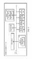
- FIG. 8is a schematic diagram of the hardware platform required for the present invention.
- exemplaryis used herein to mean serving as an example, instance, or illustration. Any aspect or design described herein as “exemplary” is not necessarily to be construed as preferred or advantageous over other aspects or designs. Rather, use of the word exemplary is intended to present concepts in a concrete fashion.
- the term “or”is intended to mean an inclusive “or” rather than an exclusive “or”. That is, unless specified otherwise, or clear from context, “X employs A or B” is intended to mean any of the natural inclusive permutations. That is if, X employs A; X employs B; or X employs both A and B, then “X employs A or B” is satisfied under any of the foregoing instances.
- FIG. 1shows a typical antenna radiation pattern produced by a directional antenna.
- the main lobe 102 of the antenna radiation patternrepresents the axis of maximum gain.
- the objective when aligning antennas and, in particular, two ground based antennas,is to align the boresight or the axis of the main lobe of both the local and the remote antennas.
- This conceptis shown in FIG. 2 .
- FIG. 3where a portable directional antenna is shown being aligned with a satellite in geosynchronous orbit having an antenna 110 .
- the radiation pattern of the satelliteis not shown, it is a similar radiation pattern to the radiation pattern of the directional antenna on the ground.
- FIG. 8An exemplary embodiment of a hardware platform used for implementing the invention is shown in schematic form in FIG. 8 .
- the hardware platformis identified as an antenna alignment unit 800 and consists of a portable computing device equipped with standard components for the storage and execution of one or more computer software applications.
- a computer readable storage mediumsuch as memory 826 , is used for the permanent storage of application instructions 824 and the satellite location database 825 .
- Memory 826is a solid state flash memory, a disk drive or any other suitable data storage device.
- Central processing unit 834executes application instructions 824 and accesses data from other components of the system through a communication channel 810 .
- the antenna alignment unit 800is preferably equipped with a video display 813 and alphanumeric input device 818 , which may be a separate keyboard or a virtual keyboard accessible through video display 813 .
- the antenna alignment unit 800is equipped with several additional components to enable the execution of the application.
- Position sensing hardware 828is provided and configured to detect an azimuth and elevation angle of the local directional antenna to facilitate the antenna alignment process.
- Imaging hardware 830preferably in the form of a video camera, is provided for generating a video source signal suitable for display on the video display 813 .
- the combination of the video camera and the display unitcan provide a view of the surrounding terrain. Necessary graphics and other information is advantageously superimposed on a background image comprising the surrounding terrain, as will be described below.
- the antenna alignment unit 800can be equipped with a GPS receiver 822 for determining the unit's position, in standard latitude and longitude coordinates.
- antenna interface hardware 832is preferably arranged so that the antenna alignment unit can send signals through the local antenna to the remote antenna. Such signals can advantageously include information specifying the GPS coordinates of the local antenna as well as its pointing status, and to receive this same information from the remote antenna.
- the apparatus for implementing the present inventioncan also include a local antenna which is to be aligned.
- antenna alignment unit 800It is not necessary that all components of antenna alignment unit 800 be housed in the same unit or located in the same place.
- position sensing hardware 828must, of necessity, be located on the local antenna or its associated support structure. Such an arrangement facilitates direct sensing of the movement and orientation of the local antenna so that this information can be monitored by the antenna alignment unit 800 as the user moves the antenna during the alignment process.
- imaging hardware 830will also preferably be located on the local antenna or its associated support structure. Such an arrangement can ensure that imaging hardware 830 is positioned to capture images in a direction aligned with the boresight orientation of the local antenna. The captured imagery is thereafter used to provide a view to the user of the actual terrain with respect to the radiation pattern of the antenna.
- the remainder of the components in antenna alignment unit 800may be located remotely from the antenna. For instance, it may be convenient for video display 813 to be located apart from the local antenna so as to facilitate viewing of the display by the user.
- Dedicated hardware implementations of the antenna alignment unit 800can include, but are not limited to, application-specific integrated circuits, programmable logic arrays, and other hardware devices which are constructed to implement the methods described herein.
- Various embodimentsbroadly include a variety of electronic and computer systems. Some embodiments implement functions in two or more specific interconnected hardware modules or devices with related control and data signals communicated between and through the modules, or as portions of an application-specific integrated circuit.
- the exemplary systemis applicable to software, firmware, and hardware implementations.
- the methods described beloware stored as software programs in a computer-readable storage medium and are configured for running on a computer processor.
- software implementationscan include, but are not limited to, distributed processing, component/object distributed processing, parallel processing, virtual machine processing, which can also be constructed to implement the methods described herein.
- While the computer-readable storage medium embodied as memory 826is shown in FIG. 8 to be a single storage medium, the term “computer-readable storage medium” should be taken to include a single medium or multiple media (e.g., a centralized or distributed database, and/or associated caches and servers) that store the one or more sets of instructions.
- the term “computer-readable storage medium”shall also be taken to include any medium that is capable of storing, encoding or carrying a set of instructions for execution by the machine and that cause the machine to perform any one or more of the methodologies of the present disclosure.
- computer-readable mediumshall accordingly be taken to include, but not be limited to, solid-state memories such as a memory card or other package that houses one or more read-only (non-volatile) memories, random access memories, or other re-writable (volatile) memories; magneto-optical or optical medium such as a disk or tape. Accordingly, the disclosure is considered to include a computer-readable medium and to include recognized equivalents and successor media, in which the software implementations herein are stored.
- the first modefacilitates the alignment of the local antenna with a ground based target antenna.
- the antenna alignment unit 800must be provided with information specifying the location of the local antenna and the target to facilitate calculating a relative bearing and elevation to which the local antenna must be adjusted. Therefore, in this embodiment of the invention, the GPS coordinates (latitude and longitude) and pointing status (i.e., which direction the antenna is pointed) of each antenna is transmitted to the other antenna. As the antennae are not aligned at this point, transmission of this information to the other antenna is accomplished via an alternate means of communication, such as WiFi, 3G cellular or any other point-to-point link which does not require transmitting information using the antenna being aligned.
- the second mode of operationis the alignment of the antenna with a satellite in geosynchronous orbit.
- the antenna alignment unit 800would determine the position of its local antenna (e.g., by using a GPS receiver).
- the location of all geosynchronous satellitesis well known and such information can therefore be stored in the satellite database 825 , or input by the operator via the alphanumeric input device 818 .
- application 824is able to calculate the relative bearing and elevation to the satellite.
- the graphical interface 400can be presented on the video display 813 described above in reference to FIG. 8 .
- the graphical interface 400is presented to an operator of the antenna alignment unit 800 when utilizing the ground-to-ground antenna alignment mode.
- the main area 401 of the graphical interfaceshows the representation of the local antenna 412 and a representation of the radiation pattern 414 of the target antenna.
- Radiation pattern 414is meant to indicate the “half power beam” region of the antenna, which, when shown means that the antennas are directly aligned.
- the radiation pattern 414 of the target antennawould look similar to the radiation pattern 416 of local antenna 412 , indicating a full strength signal.
- the indicated radiation patternsare approximations based on the relative positions of the antennae, and any graphic symbol may be used to indicate the approximate power of the antenna.
- a graphic element 416including a pointer 417 which serves as an aid for pointing the local antenna.
- Signal strength meter 410shows the strength of the signal received from the target antenna.
- Location information 402shows the location of the local antenna, including the antenna's name, it's latitude and longitude and its altitude.
- Location information 404shows similar data for the target antenna 404 .
- Alignment aid information 406includes several types of information that are useful to assist the user in aligning the local antenna with the target antenna.
- the alignment aid information 406includes bearing, elevation and distance to the target antenna.
- the alignment aid information 406also includes the current bearing and elevation of the local antenna. As the user moves the local antenna, alignment aid information 406 will change to show the current bearing and elevation information of the local antenna.
- the dotted circles representing the radiation patterns of the respective antennaewill be concentric, with the two crosses representing the boresights of the antennae being on top of each other. As the crosses get closer, the dotted circles 414 and 416 will intersect each other, indicating imminent alignment.
- the intersection of the two patternsmay be highlighted, which will result in a highlighted circular region when the crosses completely overlap, indicating alignment.
- a graphical interface 500that is similar to graphical interface 400 , but configured for the second mode of operation in which the local antenna is being aligned with a satellite in geosynchronous orbit.
- the graphic indicating the location of the target antennahas been replaced with a graphic 514 showing a satellite and its approximate location with respect to the local antenna.
- the graphic representation of the local antenna 512is also changed to indicate the nature of the local antenna. All other information in graphical interface 500 is substantially similar to the information presented in graphical interface 400 .
- the antenna alignment unit 800can be provided with information concerning the type of antenna being used so that the design of the graphic element 412 , 512 corresponds to the actual appearance of the antenna being used in a particular situation.
- the information identifying the particular type of antenna in usecan be manually entered by a user or can be automatically sensed by the antenna alignment unit.
- Techniques for automatically detecting an antennacan include detecting an impedance of the local antenna, or any other unique characteristic associated with the local antenna.
- a live video image of the surrounding terraincan be displayed in the background of the main area 401 or 501 .
- This live videois preferably provided by imaging hardware 530 .
- the resulting graphic interfaces 400 , 500will have the graphic representations of the target antenna and the local antenna superimposed over the live video image of the surrounding terrain.
- imaging hardware 530will be attached to a portion of the local antenna or its support structure so that it captures a video image that is aligned with the axis of the main lobe of the radiation pattern for the local antenna.
- FIG. 6shows the flow of processing of instructions associated with application 824 .
- the processbegins at 602 and continues at step 604 .
- the applicationobtains the coordinates of the local antenna. This step can be performed by manually receiving location data by means of the alpha-numeric input device 818 , but preferably involves utilizing GPS receiver 834 to obtain the GPS coordinates.
- the GPS coordinates and pointing status of the local antennaare transmitted to the target antenna.
- the target antennaresponds by transmitting its GPS coordinates and pointing status back to the local antenna.
- the phrase “pointing status”refers to the current azimuth and elevation angle of the local antenna.
- step 608application 824 calculates the bearing and elevation to the target antenna based on the known GPS coordinates of both the local antenna and the target antenna.
- the graphical interface 400is updated to indicate the relative bearing to the target antenna, and the current bearing information of the local antenna.
- the location information 402 , 404 for the local antenna and the target antennaare displayed as well as the alignment aid information 406 and the signal strength 410 .
- decision point 612as the user moves the local antenna according to the alignment aid information 506 , and with the aid of graphic interface 400 , a check is made to see if the antenna is aligned, and, if not, processing returns to step 608 where a new relative bearing and elevation to the target antenna is calculated.
- the newly calculated informationis displayed at step 610 and the process repeats until the antenna is aligned, at which time processing stops at step 614 .
- FIG. 7shows a flow of processing similar to the processing in FIG. 7 , but for the mode where the local antenna is being aligned to a satellite in geosynchronous orbit.
- the main differenceoccurs at step 706 where, instead of receiving the GPS coordinates of the target antenna (i.e., the satellite) from the satellite itself, those coordinates are retrieved from a database of known coordinates of satellites.
- the processingis substantially similar to the case where the local antenna is being aligned to another ground based antenna.
- the application 824can be run on any suitable hardware platform 800 , including for example a laptop, a smart phone or a tablet computing device.
- video display 813will be located remotely from the local antenna to facilitate viewing the screen as the antenna is rotated.
- the position-sensing hardware 828 and the imaging hardware 830are located physically on the antenna or its associated support structure. This ensures that as the antenna is rotated, the orientation of the antenna in space is detected by the position-sensing hardware such as to allow updating of the display.
Landscapes
- Engineering & Computer Science (AREA)
- Radar, Positioning & Navigation (AREA)
- Remote Sensing (AREA)
- Computer Networks & Wireless Communication (AREA)
- Physics & Mathematics (AREA)
- General Physics & Mathematics (AREA)
- Position Fixing By Use Of Radio Waves (AREA)
Abstract
Description
Claims (20)
Priority Applications (1)
| Application Number | Priority Date | Filing Date | Title |
|---|---|---|---|
| US13/306,482US9281559B2 (en) | 2011-11-29 | 2011-11-29 | Method for directed antenna alignment through augmented reality |
Applications Claiming Priority (1)
| Application Number | Priority Date | Filing Date | Title |
|---|---|---|---|
| US13/306,482US9281559B2 (en) | 2011-11-29 | 2011-11-29 | Method for directed antenna alignment through augmented reality |
Publications (2)
| Publication Number | Publication Date |
|---|---|
| US20130135146A1 US20130135146A1 (en) | 2013-05-30 |
| US9281559B2true US9281559B2 (en) | 2016-03-08 |
Family
ID=48466346
Family Applications (1)
| Application Number | Title | Priority Date | Filing Date |
|---|---|---|---|
| US13/306,482Active2034-07-18US9281559B2 (en) | 2011-11-29 | 2011-11-29 | Method for directed antenna alignment through augmented reality |
Country Status (1)
| Country | Link |
|---|---|
| US (1) | US9281559B2 (en) |
Cited By (11)
| Publication number | Priority date | Publication date | Assignee | Title |
|---|---|---|---|---|
| US9451220B1 (en) | 2014-12-30 | 2016-09-20 | The Directv Group, Inc. | System and method for aligning a multi-satellite receiver antenna |
| US9503177B1 (en)* | 2014-12-30 | 2016-11-22 | The Directv Group, Inc. | Methods and systems for aligning a satellite receiver dish using a smartphone or tablet device |
| US9521378B1 (en) | 2014-12-30 | 2016-12-13 | The Directv Group, Inc. | Remote display of satellite receiver information |
| US20190198969A1 (en)* | 2017-12-26 | 2019-06-27 | Limited Liability Company "Radio Gigabit" | Method for elimination of antenna angular orientation error in point-to-point communication system |
| US11233316B2 (en) | 2016-07-29 | 2022-01-25 | Hewlett-Packard Development Company, L.P. | Wireless virtual reality (VR) devices |
| US20220091808A1 (en)* | 2017-02-08 | 2022-03-24 | Immersive Robotics Pty Ltd | Antenna Control for Mobile Device Communication |
| US20240222861A1 (en)* | 2021-09-13 | 2024-07-04 | Tp-Link Corporation Limited | Antenna module and communication device having the antenna module, and communication system |
| US12058341B1 (en) | 2017-11-21 | 2024-08-06 | Immersive Robotics Pty Ltd. | Frequency component selection for image compression |
| US12096031B2 (en) | 2017-06-05 | 2024-09-17 | Immersive Robotics Pty Ltd. | Method and apparatus for digital content stream compression and decompression |
| US12355984B2 (en) | 2019-10-18 | 2025-07-08 | Immersive Robotics Pty Ltd | Content compression for network transmission |
| US12445192B2 (en)* | 2022-08-19 | 2025-10-14 | Qualcomm Incorporated | Mobile device orientation guidance for satellite-based communications |
Families Citing this family (41)
| Publication number | Priority date | Publication date | Assignee | Title |
|---|---|---|---|---|
| US8836601B2 (en) | 2013-02-04 | 2014-09-16 | Ubiquiti Networks, Inc. | Dual receiver/transmitter radio devices with choke |
| US9634373B2 (en) | 2009-06-04 | 2017-04-25 | Ubiquiti Networks, Inc. | Antenna isolation shrouds and reflectors |
| US9496620B2 (en) | 2013-02-04 | 2016-11-15 | Ubiquiti Networks, Inc. | Radio system for long-range high-speed wireless communication |
| JP6058898B2 (en)* | 2012-02-22 | 2017-01-11 | 株式会社日立国際電気 | Wireless communication apparatus, wireless communication method, and wireless communication system |
| US20160218406A1 (en) | 2013-02-04 | 2016-07-28 | John R. Sanford | Coaxial rf dual-polarized waveguide filter and method |
| US9543635B2 (en) | 2013-02-04 | 2017-01-10 | Ubiquiti Networks, Inc. | Operation of radio devices for long-range high-speed wireless communication |
| WO2015054567A1 (en) | 2013-10-11 | 2015-04-16 | Ubiquiti Networks, Inc. | Wireless radio system optimization by persistent spectrum analysis |
| JP5872594B2 (en)* | 2014-01-08 | 2016-03-01 | 株式会社東芝 | Satellite communication system and antenna adjustment method |
| EP3127187B1 (en) | 2014-04-01 | 2020-11-11 | Ubiquiti Inc. | Antenna assembly |
| US10069580B2 (en) | 2014-06-30 | 2018-09-04 | Ubiquiti Networks, Inc. | Wireless radio device alignment tools and methods |
| WO2016129667A1 (en)* | 2015-02-13 | 2016-08-18 | 日本電信電話株式会社 | Satellite signal reception characteristic estimation apparatus, method thereof, and program thereof |
| US20160240910A1 (en)* | 2015-02-18 | 2016-08-18 | Commscope Technologies Llc | Antenna azimuth alignment monitor |
| US9894536B2 (en)* | 2015-03-10 | 2018-02-13 | Aruba Networks, Inc. | Motion-controlled device for supporting planning, deployment or operation of a wireless network |
| US9966650B2 (en)* | 2015-06-04 | 2018-05-08 | Viasat, Inc. | Antenna with sensors for accurate pointing |
| US10359496B2 (en) | 2015-08-10 | 2019-07-23 | Viasat, Inc. | Satellite antenna with sensor for line-of-sight detection |
| US9781233B2 (en)* | 2015-09-04 | 2017-10-03 | Sunsight Holdings, Llc | Alignment system including remote server for point-to-point alignment of spaced apart first and second antennas and related methods |
| US10355352B2 (en)* | 2015-09-04 | 2019-07-16 | Sunsight Holdings, Llc | Alignment system for point-to-point alignment of spaced apart first and second antennas and related methods |
| CN108353232B (en) | 2015-09-11 | 2020-09-29 | 优倍快公司 | Compact broadcast access point device |
| WO2017096082A1 (en)* | 2015-12-01 | 2017-06-08 | Drexel University | Beam visualization and using augmented reality for control and interaction |
| US10361771B2 (en)* | 2016-01-22 | 2019-07-23 | Viasat, Inc. | Determining an attenuation environment of a satellite communication terminal |
| DE102016213234A1 (en) | 2016-02-12 | 2017-08-31 | Fraunhofer-Gesellschaft zur Förderung der angewandten Forschung e.V. | Device for displaying user information and corresponding method |
| WO2017137626A1 (en) | 2016-02-12 | 2017-08-17 | Fraunhofer-Gesellschaft zur Förderung der angewandten Forschung e.V. | Device for displaying user information and corresponding method |
| KR101824220B1 (en)* | 2016-05-12 | 2018-01-31 | 주식회사 케이엠더블유 | Apparatus for guiding antenna alignment |
| US20170357411A1 (en) | 2016-06-11 | 2017-12-14 | Apple Inc. | User interface for initiating a telephone call |
| US10693571B2 (en)* | 2016-06-20 | 2020-06-23 | Nec Corporation | Image generating apparatus, communication apparatus, antenna adjustment method and image generating method |
| US10116893B1 (en)* | 2017-04-28 | 2018-10-30 | Higher Ground Llc | Selectively controlling a direction of signal transmission using adaptive augmented reality |
| US10267888B2 (en)* | 2017-04-28 | 2019-04-23 | Higher Ground Llc | Pointing an antenna at a signal source using augmented reality |
| US11765114B2 (en) | 2017-05-16 | 2023-09-19 | Apple Inc. | Voice communication method |
| US11475181B2 (en) | 2018-04-05 | 2022-10-18 | Starry, Inc. | System and method for facilitating installation of user nodes in fixed wireless data network |
| US11924708B2 (en) | 2018-12-05 | 2024-03-05 | Sony Group Corporation | Information processing device and information processing method |
| US11076303B2 (en) | 2018-12-18 | 2021-07-27 | Sunsight Holdings, Llc | Antenna alignment tool generating earth browser file and related methods |
| CN119210569B (en)* | 2021-08-06 | 2025-07-22 | 华为技术有限公司 | Transmission control method and related device in satellite communication system |
| US12425511B2 (en) | 2021-08-31 | 2025-09-23 | Apple Inc. | Methods and systems of interfaces for initiating communications using terrestrial and non-terrestrial networks |
| US11693529B2 (en) | 2021-08-31 | 2023-07-04 | Apple Inc. | Methods and interfaces for initiating communications |
| CN113993066B (en)* | 2021-09-15 | 2024-07-12 | 北京电子工程总体研究所 | Multi-directional microwave antenna alignment method and system |
| CN114039677B (en)* | 2022-01-11 | 2022-04-26 | 深圳市永达电子信息股份有限公司 | Automatic alignment method and system for point-to-point wireless communication equipment |
| CN118525458A (en)* | 2022-02-04 | 2024-08-20 | 三菱电机株式会社 | Position estimation device, position estimation method, and program |
| EP4537426A1 (en)* | 2022-06-29 | 2025-04-16 | Viasat, Inc. | Self-installation of phased array antenna using augmented reality |
| US12395237B2 (en) | 2022-07-18 | 2025-08-19 | Qualcomm Incorporated | Assistance data for orienting a mobile device for satellite-based communications |
| US12417596B2 (en) | 2022-09-23 | 2025-09-16 | Apple Inc. | User interfaces for managing live communication sessions |
| WO2024107500A1 (en)* | 2022-11-15 | 2024-05-23 | Qualcomm Incorporated | Feedback associated with alignment of a user equipment antenna with a satellite |
Citations (7)
| Publication number | Priority date | Publication date | Assignee | Title |
|---|---|---|---|---|
| US5390125A (en)* | 1990-02-05 | 1995-02-14 | Caterpillar Inc. | Vehicle position determination system and method |
| US20030025791A1 (en)* | 2001-06-29 | 2003-02-06 | Kenneth Kaylor | Trailer mounted surveillance system |
| US20080258986A1 (en)* | 2007-02-28 | 2008-10-23 | Celite Milbrandt | Antenna array for a hi/lo antenna beam pattern and method of utilization |
| US20080284669A1 (en)* | 2007-05-18 | 2008-11-20 | Matthew Hunton | System and method for remote antenna positioning data acquisition |
| US20090033576A1 (en)* | 2007-08-02 | 2009-02-05 | Embarq Holdings Company, Llc | System and method for re-aligning antennas |
| US7577316B2 (en)* | 2000-10-06 | 2009-08-18 | Vederi, Llc | System and method for creating, storing and utilizing images of a geographic location |
| US20100201571A1 (en)* | 2005-12-28 | 2010-08-12 | The Directv Group, Inc. | Command, control and communications with intelligent antennas |
- 2011
- 2011-11-29USUS13/306,482patent/US9281559B2/enactiveActive
Patent Citations (7)
| Publication number | Priority date | Publication date | Assignee | Title |
|---|---|---|---|---|
| US5390125A (en)* | 1990-02-05 | 1995-02-14 | Caterpillar Inc. | Vehicle position determination system and method |
| US7577316B2 (en)* | 2000-10-06 | 2009-08-18 | Vederi, Llc | System and method for creating, storing and utilizing images of a geographic location |
| US20030025791A1 (en)* | 2001-06-29 | 2003-02-06 | Kenneth Kaylor | Trailer mounted surveillance system |
| US20100201571A1 (en)* | 2005-12-28 | 2010-08-12 | The Directv Group, Inc. | Command, control and communications with intelligent antennas |
| US20080258986A1 (en)* | 2007-02-28 | 2008-10-23 | Celite Milbrandt | Antenna array for a hi/lo antenna beam pattern and method of utilization |
| US20080284669A1 (en)* | 2007-05-18 | 2008-11-20 | Matthew Hunton | System and method for remote antenna positioning data acquisition |
| US20090033576A1 (en)* | 2007-08-02 | 2009-02-05 | Embarq Holdings Company, Llc | System and method for re-aligning antennas |
Non-Patent Citations (5)
| Title |
|---|
| H. Abbott et al., Land-vehicle navigation using GPS, Proceedings of the IEEE, vol. 87(1), p. 145-162, 1999.* |
| Installation Manual DIRECTV Multi-Satellite Dish Antenna with Integrated Triple LNB and Built-in Multi-Switch, DIRECTV, p. 1-12, Apr. 17, 2003.* |
| Output device. (2006). In High definition: A-Z Guide to personal technology. Boston, MA: Houghton Mifflin. Retrieved from http://search.credoreference.com/content/entry/hmhighdef/output-device/0.* |
| SatHunter. Manual [online]. 200-[retrieved on Sep. 15, 2014]. Retrieved from the Internet: .* |
| SatHunter. Manual [online]. 200-[retrieved on Sep. 15, 2014]. Retrieved from the Internet: <URL: http://sathunter.com/index.php>.* |
Cited By (15)
| Publication number | Priority date | Publication date | Assignee | Title |
|---|---|---|---|---|
| US10805580B2 (en) | 2014-12-30 | 2020-10-13 | The Directv Group, Inc. | Remote display of satellite receiver information |
| US9451220B1 (en) | 2014-12-30 | 2016-09-20 | The Directv Group, Inc. | System and method for aligning a multi-satellite receiver antenna |
| US9521378B1 (en) | 2014-12-30 | 2016-12-13 | The Directv Group, Inc. | Remote display of satellite receiver information |
| US9888217B2 (en) | 2014-12-30 | 2018-02-06 | The Directv Group, Inc | Remote display of satellite receiver information |
| US9503177B1 (en)* | 2014-12-30 | 2016-11-22 | The Directv Group, Inc. | Methods and systems for aligning a satellite receiver dish using a smartphone or tablet device |
| US11233316B2 (en) | 2016-07-29 | 2022-01-25 | Hewlett-Packard Development Company, L.P. | Wireless virtual reality (VR) devices |
| US20220091808A1 (en)* | 2017-02-08 | 2022-03-24 | Immersive Robotics Pty Ltd | Antenna Control for Mobile Device Communication |
| US12096031B2 (en) | 2017-06-05 | 2024-09-17 | Immersive Robotics Pty Ltd. | Method and apparatus for digital content stream compression and decompression |
| US12058341B1 (en) | 2017-11-21 | 2024-08-06 | Immersive Robotics Pty Ltd. | Frequency component selection for image compression |
| US10541462B2 (en)* | 2017-12-26 | 2020-01-21 | Limited Liability Company “Radio Gigabit” | Method for elimination of antenna angular orientation error in point-to-point communication system |
| US20190198969A1 (en)* | 2017-12-26 | 2019-06-27 | Limited Liability Company "Radio Gigabit" | Method for elimination of antenna angular orientation error in point-to-point communication system |
| US12355984B2 (en) | 2019-10-18 | 2025-07-08 | Immersive Robotics Pty Ltd | Content compression for network transmission |
| US20240222861A1 (en)* | 2021-09-13 | 2024-07-04 | Tp-Link Corporation Limited | Antenna module and communication device having the antenna module, and communication system |
| US12237583B2 (en)* | 2021-09-13 | 2025-02-25 | Tp-Link Corporation Limited | Antenna module and communication device having the antenna module, and communication system |
| US12445192B2 (en)* | 2022-08-19 | 2025-10-14 | Qualcomm Incorporated | Mobile device orientation guidance for satellite-based communications |
Also Published As
| Publication number | Publication date |
|---|---|
| US20130135146A1 (en) | 2013-05-30 |
Similar Documents
| Publication | Publication Date | Title |
|---|---|---|
| US9281559B2 (en) | Method for directed antenna alignment through augmented reality | |
| US10613231B2 (en) | Portable GNSS survey system | |
| US6807485B1 (en) | Integrated position and direction system with radio communication for updating data | |
| US8717233B2 (en) | Satellite signal multipath mitigation in GNSS devices | |
| EP2573513B1 (en) | A computer implemented method for marking a point of interest in an image and a navigation device | |
| US20160198286A1 (en) | Sensor installation location determination support system and sensor installation location determination support method | |
| US10164723B2 (en) | Adaptive augmented reality satellite acquisition | |
| US9503177B1 (en) | Methods and systems for aligning a satellite receiver dish using a smartphone or tablet device | |
| CN113295174B (en) | Lane-level positioning method, related device, equipment and storage medium | |
| CA2925850C (en) | Target direction determination method and system | |
| US20130203448A1 (en) | Terminal and method for recognizing communication target | |
| WO2024083082A1 (en) | Compass calibration method and apparatus, electronic device and readable storage medium | |
| US10530051B2 (en) | Antenna alignment device and methods for aligning antennas | |
| KR20030010982A (en) | position coordinate data transmission device using navigation system | |
| KR100963680B1 (en) | Coordinate measuring device and method of a remote target | |
| US11143508B2 (en) | Handheld device for calculating locations coordinates for visible but uncharted remote points | |
| JP2010098720A (en) | Device, method and system for constructing and outputting image | |
| CN118259576A (en) | Smart watch, adjusting method and adjusting device | |
| US20190148813A1 (en) | Imaging system and method for accurately directing antennas | |
| KR20130026031A (en) | Apparatas and method for providing automatic location information calibration of a muti-path area in a portable terminal | |
| US11475181B2 (en) | System and method for facilitating installation of user nodes in fixed wireless data network | |
| JP2002236259A (en) | Unattended guide system and unattended guide method for observation object | |
| JP4109684B2 (en) | Mobile station navigation device | |
| EP3358371B1 (en) | Antenna alignment device and methods for aligning antennas | |
| JP3908350B2 (en) | Monitoring device |
Legal Events
| Date | Code | Title | Description |
|---|---|---|---|
| AS | Assignment | Owner name:HARRIS CORPORATION, FLORIDA Free format text:ASSIGNMENT OF ASSIGNORS INTEREST;ASSIGNORS:RANSOM, NATHAN;LEE, MYUNG;REEL/FRAME:027290/0116 Effective date:20111109 | |
| STCF | Information on status: patent grant | Free format text:PATENTED CASE | |
| AS | Assignment | Owner name:HARRIS GLOBAL COMMUNICATIONS, INC., NEW YORK Free format text:CHANGE OF NAME;ASSIGNOR:HARRIS SOLUTIONS NY, INC.;REEL/FRAME:047598/0361 Effective date:20180417 Owner name:HARRIS SOLUTIONS NY, INC., NEW YORK Free format text:ASSIGNMENT OF ASSIGNORS INTEREST;ASSIGNOR:HARRIS CORPORATION;REEL/FRAME:047600/0598 Effective date:20170127 | |
| MAFP | Maintenance fee payment | Free format text:PAYMENT OF MAINTENANCE FEE, 4TH YEAR, LARGE ENTITY (ORIGINAL EVENT CODE: M1551); ENTITY STATUS OF PATENT OWNER: LARGE ENTITY Year of fee payment:4 | |
| MAFP | Maintenance fee payment | Free format text:PAYMENT OF MAINTENANCE FEE, 8TH YEAR, LARGE ENTITY (ORIGINAL EVENT CODE: M1552); ENTITY STATUS OF PATENT OWNER: LARGE ENTITY Year of fee payment:8 |