US9279325B2 - Turbomachine wheel assembly having slotted flanges - Google Patents
Turbomachine wheel assembly having slotted flangesDownload PDFInfo
- Publication number
- US9279325B2 US9279325B2US13/672,253US201213672253AUS9279325B2US 9279325 B2US9279325 B2US 9279325B2US 201213672253 AUS201213672253 AUS 201213672253AUS 9279325 B2US9279325 B2US 9279325B2
- Authority
- US
- United States
- Prior art keywords
- wheel assembly
- fastener
- mechanical fastener
- flange
- wheel
- Prior art date
- Legal status (The legal status is an assumption and is not a legal conclusion. Google has not performed a legal analysis and makes no representation as to the accuracy of the status listed.)
- Active, expires
Links
Images


Classifications
- F—MECHANICAL ENGINEERING; LIGHTING; HEATING; WEAPONS; BLASTING
- F01—MACHINES OR ENGINES IN GENERAL; ENGINE PLANTS IN GENERAL; STEAM ENGINES
- F01D—NON-POSITIVE DISPLACEMENT MACHINES OR ENGINES, e.g. STEAM TURBINES
- F01D5/00—Blades; Blade-carrying members; Heating, heat-insulating, cooling or antivibration means on the blades or the members
- F01D5/02—Blade-carrying members, e.g. rotors
- F01D5/022—Blade-carrying members, e.g. rotors with concentric rows of axial blades
- F—MECHANICAL ENGINEERING; LIGHTING; HEATING; WEAPONS; BLASTING
- F01—MACHINES OR ENGINES IN GENERAL; ENGINE PLANTS IN GENERAL; STEAM ENGINES
- F01D—NON-POSITIVE DISPLACEMENT MACHINES OR ENGINES, e.g. STEAM TURBINES
- F01D5/00—Blades; Blade-carrying members; Heating, heat-insulating, cooling or antivibration means on the blades or the members
- F01D5/02—Blade-carrying members, e.g. rotors
- F01D5/06—Rotors for more than one axial stage, e.g. of drum or multiple disc type; Details thereof, e.g. shafts, shaft connections
- F01D5/066—Connecting means for joining rotor-discs or rotor-elements together, e.g. by a central bolt, by clamps
- F—MECHANICAL ENGINEERING; LIGHTING; HEATING; WEAPONS; BLASTING
- F16—ENGINEERING ELEMENTS AND UNITS; GENERAL MEASURES FOR PRODUCING AND MAINTAINING EFFECTIVE FUNCTIONING OF MACHINES OR INSTALLATIONS; THERMAL INSULATION IN GENERAL
- F16B—DEVICES FOR FASTENING OR SECURING CONSTRUCTIONAL ELEMENTS OR MACHINE PARTS TOGETHER, e.g. NAILS, BOLTS, CIRCLIPS, CLAMPS, CLIPS OR WEDGES; JOINTS OR JOINTING
- F16B39/00—Locking of screws, bolts or nuts
- F16B39/01—Locking of screws, bolts or nuts specially adapted to prevent loosening at extreme temperatures
- B—PERFORMING OPERATIONS; TRANSPORTING
- B23—MACHINE TOOLS; METAL-WORKING NOT OTHERWISE PROVIDED FOR
- B23P—METAL-WORKING NOT OTHERWISE PROVIDED FOR; COMBINED OPERATIONS; UNIVERSAL MACHINE TOOLS
- B23P15/00—Making specific metal objects by operations not covered by a single other subclass or a group in this subclass
- B23P15/006—Making specific metal objects by operations not covered by a single other subclass or a group in this subclass turbine wheels
- Y—GENERAL TAGGING OF NEW TECHNOLOGICAL DEVELOPMENTS; GENERAL TAGGING OF CROSS-SECTIONAL TECHNOLOGIES SPANNING OVER SEVERAL SECTIONS OF THE IPC; TECHNICAL SUBJECTS COVERED BY FORMER USPC CROSS-REFERENCE ART COLLECTIONS [XRACs] AND DIGESTS
- Y10—TECHNICAL SUBJECTS COVERED BY FORMER USPC
- Y10T—TECHNICAL SUBJECTS COVERED BY FORMER US CLASSIFICATION
- Y10T29/00—Metal working
- Y10T29/49—Method of mechanical manufacture
- Y10T29/49481—Wheel making
Definitions
- the subject matter disclosed hereinrelates to the art of turbomachines and, more particularly, to a turbomachine wheel assembly having slotted flanges.
- Gas turbomachinesinclude a compressor portion linked to a turbine portion through a common compressor/turbine shaft and a combustor assembly.
- the compressor portionguides compressed air flow through a number of sequential stages toward the combustor assembly.
- the compressed air flowmixes with a fuel to form a combustible mixture.
- the combustible mixtureis combusted in the combustor assembly to form hot gases.
- the hot gasesare guided to the turbine portion through a transition piece.
- the hot gasesexpand through the turbine portion acting upon turbine blades mounted on wheels to create work that is output, for example, to power a generator, a pump, or to provide power to a vehicle.
- Multiple wheelsare connected to spacers by bolted joints to form a stacked wheel assembly.
- D-nutsare employed at one end of a fastener portion of the bolted joint.
- the D-nutsact upon one another to prevent rotation of the fastener portion while a nut is tightened on an opposing end.
- the D-nutsact upon an outer/inner, flange extensions/arms on the wheel. In such cases, the D-nuts apply an radial force to the outer/inner flange extensions/arms.
- a turbomachine wheel assembly having slotted flangesincludes a turbomachine wheel having a first wheel arm and a second, opposing wheel arm.
- the first wheel armincludes a first flange having a first radially outer surface and the second wheel arm includes a second flange having a second radially outer surface.
- the second flangeincludes a fastener retaining member extending axially outwardly from the second radially outer surface and an opening extending axially through the second flange at the fastener retaining member.
- the fastener retaining memberincludes at least one wall section extending radially inward from the second radial outer surface
- a method of joining a turbomachine spacer to a wheel assemblyincludes installing a mechanical fastener at a fastener retaining member extending axially outwardly from a diametric surface adjacent a radially outer surface of a flange provided on the wheel assembly. Rotation of the mechanical fastener is constrained through an interaction with the fastener retaining member, positioning a spacer adjacent to the wheel assembly. A passage extending through the spacer is aligned with an opening extending through the flange at the fastener retaining member and a mechanical fastener element is positioned through the passage and into the opening. The mechanical fastener element operatively connects with the mechanical fastener.
- FIG. 1is a schematic view of a turbomachine stacked wheel assembly connected in accordance with an exemplary embodiment
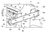
- FIG. 2is a cross-sectional partial perspective view of a bolted joint of the stacked wheel assembly of FIG. 1 ;
- FIG. 3is a partially cut-away perspective view of a mechanical fastener retaining member provided at the bolted joint of FIG. 2 ;
- FIG. 4is a partially exploded view of the bolted joint of FIG. 2 ;
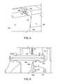
- FIG. 5is a partial perspective view of a mechanical fastener retaining member in accordance with an aspect of the exemplary embodiment
- FIG. 6is a cross-sectional plan view of a bolted joint in accordance with another aspect of an exemplary embodiment.
- FIG. 7is a partial perspective view of the bolted joint of FIG. 6 .
- Turbomachine stage 2includes a spacer 6 operatively connected between a first wheel assembly 10 and a second wheel assembly 12 .
- Spacer 6includes a wheel mounting zone 18 including a first rabbet 20 defining a first wheel surface 21 and a second rabbet 22 defining a second wheel surface 23 .
- a plurality of passages, one of which is indicated at 24extends through spacer 6 at wheel mounting zone 18 .
- First wheel assembly 10includes a turbomachine wheel 34 including a first wheel arm 40 and a second, opposing wheel arm 42 .
- First wheel arm 40includes a first flange 46 and second wheel arm 42 includes a second flange 48 .
- First flange 46includes a first radial outer surface 54 and second flange 48 includes a second radial outer surface 56 .
- the term “radial outer surface”should be understood to describe a surface that projects outwardly from a longitudinal axis “A” of turbomachine stage 2 .
- First flange 46also includes a first plurality of openings, one of which is indicated at 59 and second flange 48 includes a second plurality of openings, one of which is indicated at 61 .
- second flange 48is coupled to spacer 6 . More specifically, second flange 48 is shown to include an inner diametric surface 63 and an outer diametric surface 64 . Outer diametric surface 64 abuts spacer 6 such that openings 61 register with passages 24 .
- turbomachine wheel 34includes a plurality of fastener retaining members, one of which is indicated at 70 in FIG. 3 .
- Fastener retaining members 70are spaced one from another and extend axially outwardly from inner diametric surface 63 forming a plurality of slots (not separately labeled).
- the term “axially outwardly”should be understood that fastener retaining member 70 projects outwardly from second flange 48 along longitudinal axis “A”.
- Fastener retaining member 70includes a first wall section 72 and a second wall section 73 .
- First and second wall sections 72 and 73include corresponding first and second surfaces 75 and 76 that extend generally radially along fastener retaining member 70 .
- First and second wall sections 72 and 73also include corresponding first and second keyways 80 and 82 that extend into respective ones of first and second surfaces 75 and 76 .
- First and second surfaces 75 and 76 and first and second keyways 80 and 82provide an axial retention feature for a mechanical fastener, such as shown at 90 , when assembled in a vertical orientation.
- Mechanical fastener 90takes the form of a D-nut 92 that is sized so as to be positioned between adjacent fastener retaining member 70 .
- D-nut 92includes a key element or wing 95 that extends into first keyways 80 and another keyway (not shown) provided on an adjacent fastener retaining member (also not shown).
- Bolt 101includes a first threaded end 102 and a second threaded end 103 .
- First threaded end 102engages with threads (not separately labeled) provided in D-nut 92 and another mechanical fastener 108 is operatively coupled to the second threaded end 103 .
- the another mechanical fastener 108takes the form of a nut 110 that is provided to secure a wheel arm 112 of second wheel assembly 12 to form a bolted joint. Rotation of D-nut 92 is constrained when nut 110 is rotated or tightened causing an outer flat surface (not separately labeled) of D-nut 92 to abut one of wall sections 72 and 73 .
- the exemplary embodimentsprovide a fastener retaining member that constrains rotation of mechanical fasteners used in a bolted joint of a turbomachine.
- the fastener retaining memberincludes surfaces that interact with a mechanical fastener. In this manner, radial outer forces acting on an outer edge of the flange are reduced or eliminated. Controlling the radial outer forces leads to reduced wheel damage.
- the particular geometry of the fastener retaining elementmay vary.
- FIG. 5illustrates a fastener retaining element 116 having a first wall section 118 and a second wall section (not shown), the first wall section 118 and second wall section include tapered surfaces such as shown at 121 in connection with first wall surface 118 .
- Fastener retaining element 116is also shown to include keyways, one of which is shown at 124 .
- the tapered surfacesfacilitate a more uniform contact between side portions 126 of a D-nut 128 , wall surface 118 , and a wall surface on an adjacent fastener retaining member (not shown).
- a key element 129 on D-nut 128extends into keyway 124 to facilitate axial retention as discussed above. It should also be understood that the fastener retaining element may be employed in many wheel assembly configurations.
- a turbomachine wheel 137includes a wheel arm 140 having a flange 142 with a radial outer surface 144 .
- Flange 142is also shown to include an outer diametric surface 148 and an inner diametric surface 150 .
- Outer diametric surface 148includes a rabbet 152 that includes a spacer support surface 155 .
- Spacer support surface 155supports, at least in part, a spacer 158 .
- a plurality of fastener retaining elements, one of which is indicated at 160is provided on inner diametric surface 150 .
- Each fastener retaining element 160includes first and second keyways, one of which is indicated at 163 .
- Keyways 163are configured to receive a key element or wing 170 formed on a mechanical fastener 176 .
- interaction between key elements 170 and keyways 163provide axial retention of mechanical fastener 176 when installed in a vertical position, while adjacent fastener receiving elements 160 constrain rotation of mechanical fastener 176 to facilitate a connection with a bolt 180 to establish a bolted joint.
Landscapes
- Engineering & Computer Science (AREA)
- General Engineering & Computer Science (AREA)
- Mechanical Engineering (AREA)
- Structures Of Non-Positive Displacement Pumps (AREA)
Abstract
Description
Claims (20)
Priority Applications (1)
| Application Number | Priority Date | Filing Date | Title |
|---|---|---|---|
| US13/672,253US9279325B2 (en) | 2012-11-08 | 2012-11-08 | Turbomachine wheel assembly having slotted flanges |
Applications Claiming Priority (1)
| Application Number | Priority Date | Filing Date | Title |
|---|---|---|---|
| US13/672,253US9279325B2 (en) | 2012-11-08 | 2012-11-08 | Turbomachine wheel assembly having slotted flanges |
Publications (2)
| Publication Number | Publication Date |
|---|---|
| US20140127033A1 US20140127033A1 (en) | 2014-05-08 |
| US9279325B2true US9279325B2 (en) | 2016-03-08 |
Family
ID=50622531
Family Applications (1)
| Application Number | Title | Priority Date | Filing Date |
|---|---|---|---|
| US13/672,253Active2034-11-01US9279325B2 (en) | 2012-11-08 | 2012-11-08 | Turbomachine wheel assembly having slotted flanges |
Country Status (1)
| Country | Link |
|---|---|
| US (1) | US9279325B2 (en) |
Cited By (1)
| Publication number | Priority date | Publication date | Assignee | Title |
|---|---|---|---|---|
| US20250075637A1 (en)* | 2023-08-29 | 2025-03-06 | Rtx Corporation | Fastener assembly for a gas turbine engine |
Families Citing this family (1)
| Publication number | Priority date | Publication date | Assignee | Title |
|---|---|---|---|---|
| US11644071B2 (en)* | 2019-07-08 | 2023-05-09 | Honeywell International Inc. | Rotor drive key assembly |
Citations (104)
| Publication number | Priority date | Publication date | Assignee | Title |
|---|---|---|---|---|
| US3597110A (en)* | 1969-10-23 | 1971-08-03 | Gen Electric | Joint construction |
| US3697130A (en) | 1971-04-20 | 1972-10-10 | American Seating Co | Connector assembly for chairs |
| US3764059A (en) | 1972-10-03 | 1973-10-09 | S Knowles | Stud lock |
| US3779579A (en) | 1972-07-07 | 1973-12-18 | Smith & Co Inc Gordon | Wheel mounting assembly |
| US3789635A (en) | 1972-03-17 | 1974-02-05 | Brunt J Van | Stud lock |
| US3821973A (en) | 1973-08-17 | 1974-07-02 | Nupla Corp | Replaceable hammer tip |
| US3830085A (en) | 1973-03-19 | 1974-08-20 | Emkart Corp | Lock device including stud locking u-shaped keeper |
| US3866524A (en) | 1973-05-11 | 1975-02-18 | Jr Hampton E Forbes | Vehicle window ventilator |
| US3874824A (en) | 1973-10-01 | 1975-04-01 | Avco Corp | Turbomachine rotor assembly |
| US3911548A (en) | 1974-10-02 | 1975-10-14 | Interpace Corp | Method for replacing existing utility pole without disturbing hardware mounted thereon |
| US3941506A (en) | 1974-09-05 | 1976-03-02 | Carrier Corporation | Rotor assembly |
| US3975804A (en) | 1976-01-14 | 1976-08-24 | Dzus Fastener Co., Inc. | Front insert receptacle |
| US4056035A (en) | 1976-08-23 | 1977-11-01 | Benny Centera | Stud lock |
| US4066184A (en) | 1976-07-13 | 1978-01-03 | Conch L.N.G. | Thermal insulation systems |
| US4066372A (en) | 1976-04-05 | 1978-01-03 | Interpace Corporation | Slotted flange connector useable in a method for replacing an existing utility pole without disturbing hardware mounted thereon |
| US4236873A (en) | 1978-09-20 | 1980-12-02 | United Technologies Corporation | Wind turbine blade retention device |
| US4308646A (en) | 1979-05-02 | 1982-01-05 | Dzus Fastener Co., Inc. | Front insert receptacle |
| US4319776A (en) | 1979-05-11 | 1982-03-16 | E. J. Brooks Company | Seal |
| US4414618A (en) | 1982-01-25 | 1983-11-08 | Jacobson Darwin J | Lamp shade adjuster and holder |
| US4538746A (en) | 1983-06-29 | 1985-09-03 | Vending Components, Inc. | Keg-tapping assembly |
| EP0187264A1 (en) | 1984-12-12 | 1986-07-16 | Paul Journee S.A. | Latch with a keyless locking means |
| US4651596A (en) | 1985-09-24 | 1987-03-24 | Eem Rachanski Enterprises, Inc. | Different taper stud remover/installer |
| US4781502A (en) | 1987-10-26 | 1988-11-01 | The United States Of America As Represented By The Secretary Of The Air Force | Anti-rotation locking device for fasteners |
| US4844694A (en)* | 1986-12-03 | 1989-07-04 | Societe Nationale D'etude Et De Construction De Moteurs D'aviation (Snecma) | Fastening spindle and method of assembly for attaching rotor elements of a gas-turbine engine |
| EP0322561A2 (en) | 1987-12-24 | 1989-07-05 | Tecumseh Products Company | Hermetic compressor assembly |
| EP0339663A1 (en) | 1988-04-29 | 1989-11-02 | Chrysler Corporation | Automatic four-speed transmission |
| US4887949A (en)* | 1988-03-30 | 1989-12-19 | United Technologies Corporation | Bolt retention apparatus |
| EP0365394A1 (en) | 1988-10-11 | 1990-04-25 | Robert Tailhades | Additional locking means for a mortise espagnolette |
| EP0376641A1 (en) | 1988-12-27 | 1990-07-04 | E. Marlowe Goble | Ligament anchor system |
| EP0392391A2 (en) | 1989-04-11 | 1990-10-17 | Ford-Werke Aktiengesellschaft | Four speed transaxle for automotive vehicles |
| US4989312A (en) | 1990-02-20 | 1991-02-05 | Maddalena Kris L | Universal wheel puller and lock plate compressor tool |
| US5052891A (en)* | 1990-03-12 | 1991-10-01 | General Motors Corporation | Connection for gas turbine engine rotor elements |
| EP0450495A2 (en) | 1990-04-04 | 1991-10-09 | Nissan Motor Co., Ltd. | Continuously variable traction roller transmission with a hydraulic control system |
| EP0455490A2 (en) | 1990-05-02 | 1991-11-06 | AMSTED Industries Incorporated | Restrained pipe joint |
| EP0463751A1 (en) | 1990-06-25 | 1992-01-02 | The Babcock & Wilcox Company | Locking bolt assembly |
| EP0464316A1 (en) | 1990-06-30 | 1992-01-08 | KABUSHIKI KAISHA KOBE SEIKO SHO also known as Kobe Steel Ltd. | Screw compressor |
| EP0491526A1 (en) | 1990-12-15 | 1992-06-24 | Sanden Corporation | Slant plate type compressor with variable displacement mechanism |
| EP0498552A1 (en) | 1991-01-28 | 1992-08-12 | Sanden Corporation | Slant plate type compressor with variable displacement mechanism |
| EP0499342A2 (en) | 1988-10-25 | 1992-08-19 | Sanden Corporation | Slant plate type compressor |
| EP0526060A2 (en) | 1991-07-22 | 1993-02-03 | General Electric Company | Method for assembling armatures |
| EP0547812A1 (en) | 1991-12-05 | 1993-06-23 | Sanden Corporation | Slant plate type compressor with variable displacement mechanism |
| EP0550218A1 (en) | 1991-12-30 | 1993-07-07 | General Electric Company | Gas turbine combustors |
| EP0556514A2 (en) | 1991-12-23 | 1993-08-25 | General Electric Company | Combined heat shield and retainer for turbine assembly bolt |
| EP0568944A1 (en) | 1992-05-08 | 1993-11-10 | Sanden Corporation | Swash plate type compressor with variable displacement mechanism |
| EP0572202A1 (en) | 1992-05-27 | 1993-12-01 | General Electric Company | Apparatus and methods for reducing fuel/air concentration oscillations in gas turbine combustors |
| EP0614199A1 (en) | 1993-03-01 | 1994-09-07 | AT&T Corp. | Modular transformer structure |
| EP0616111A1 (en) | 1993-03-11 | 1994-09-21 | ROLLS-ROYCE plc | Gas turbine combustion chamber discharge support |
| US5350278A (en)* | 1993-06-28 | 1994-09-27 | The United States Of America As Represented By The Secretary Of The Air Force | Joining means for rotor discs |
| US5388963A (en) | 1993-07-02 | 1995-02-14 | United Technologies Corporation | Flange for high speed rotors |
| EP0639692A1 (en) | 1993-04-26 | 1995-02-22 | United Technologies Corporation | Mechanical damper |
| EP0643225A1 (en) | 1993-09-14 | 1995-03-15 | Sanden Corporation | Hermetic motor driven scroll apparatus having improved lubricating mechanism |
| EP0666423A1 (en) | 1994-01-26 | 1995-08-09 | Coltec Industries Inc | Surge detection system using engine signature |
| EP0672821A1 (en) | 1994-02-09 | 1995-09-20 | ROLLS-ROYCE plc | Air cooled gas turbine aerofoil |
| EP0689782A1 (en) | 1994-06-29 | 1996-01-03 | WANG, Yuan Liang | A wheeled luggage |
| EP0702171A1 (en) | 1994-08-19 | 1996-03-20 | Honda Giken Kogyo Kabushiki Kaisha | Tandem type hydraulic clutch system |
| EP0714645A1 (en) | 1994-12-01 | 1996-06-05 | JOHNSON & JOHNSON PROFESSIONAL Inc. | Modular knee prosthesis |
| US5529509A (en) | 1995-05-12 | 1996-06-25 | Alcoa Fujikura Limited | Interlocking ground terminal |
| US5536144A (en) | 1994-10-13 | 1996-07-16 | General Motors Corporation | Turbocharger turbine wheel and shaft assembly |
| US5537814A (en) | 1994-09-28 | 1996-07-23 | General Electric Company | High pressure gas generator rotor tie rod system for gas turbine engine |
| EP0751596A2 (en) | 1995-06-29 | 1997-01-02 | Flexiform Business Furniture Limited | Improvements in and relating to furniture and other installations |
| EP0820739A2 (en) | 1996-07-23 | 1998-01-28 | Johnson & Johnson Professional, Inc. | Fastening system for a modular knee prosthesis |
| EP0851124A1 (en) | 1996-12-27 | 1998-07-01 | Sanden Corporation | Oldham coupling mechanism of scroll-type fluid displacement apparatus |
| US5796202A (en) | 1997-02-20 | 1998-08-18 | General Electric Co. | Tie bolt and stacked wheel assembly for the rotor of a rotary machine |
| EP0770186B1 (en) | 1994-07-12 | 1998-09-30 | Dzus Fastener Europe Limited | A fastening device |
| EP0876782A1 (en) | 1997-05-07 | 1998-11-11 | William James Holloway Watts | Artist's kit |
| US5927063A (en) | 1997-08-19 | 1999-07-27 | Exxon Chemical Patents Inc. | High efficiency reformed methanol gas turbine power plants |
| US6026521A (en) | 1998-11-23 | 2000-02-22 | Atkins; Gary B. | Two-piece water closet ring |
| DE10007368A1 (en) | 2000-02-18 | 2001-09-06 | Rainer Schoettl | Examination method and appliance for facial bone structure through chewing plane involve height adjustment elements, and press-stud locking sleeves. |
| US6389814B2 (en) | 1995-06-07 | 2002-05-21 | Clean Energy Systems, Inc. | Hydrocarbon combustion power generation system with CO2 sequestration |
| US6427885B1 (en) | 1999-10-20 | 2002-08-06 | Dennis D. Dexel | Spare tire lock and lug wrench placement device |
| US6499957B1 (en)* | 1998-06-27 | 2002-12-31 | Miu Aero Engines Gmbh | Rotor for a turbomachine |
| US6499969B1 (en) | 2000-05-10 | 2002-12-31 | General Motors Corporation | Conically jointed turbocharger rotor |
| US20030068918A1 (en) | 2001-10-06 | 2003-04-10 | Christensson Eddy K.G. | Biomedical patient electrode clasp with automatic stud lock |
| US6641326B2 (en)* | 2001-12-21 | 2003-11-04 | General Electric Company | Removable stud for joining casing flanges |
| US6672630B2 (en)* | 2001-09-20 | 2004-01-06 | Nuovo Pignone Holding S.P.A. | Flange for connection between an axial compressor and high-pressure rotor disc unit in a gas turbine |
| US20040031116A1 (en) | 2002-08-15 | 2004-02-19 | Coleman Lorenzo Jacob | Combination of push broom and house broom |
| EP1424447A1 (en) | 2001-09-04 | 2004-06-02 | Shanghai Meglev Transportation Development Co. Ltd. | A adjustable bearing |
| US20050031731A1 (en) | 2003-06-20 | 2005-02-10 | Manuel Gomes | Quick assembly hot runner nozzle design |
| US6855005B2 (en) | 2001-03-20 | 2005-02-15 | Iusa-Ge, S. De R.L. De C.V. | Double fluke security sealing ring for watt-hour meters |
| US20050076683A1 (en) | 2003-10-10 | 2005-04-14 | An-Hung Chen | Multi-stage motorcycle lock |
| US20050089385A1 (en) | 2003-08-21 | 2005-04-28 | Yen-Tseng Lin | Anti-rotation locking nut and bolt |
| EP1536091A1 (en) | 2003-11-27 | 2005-06-01 | Chen, Meng-Fu | Motorcycle lock with multi-stage locking and unlocking |
| US20050191151A1 (en) | 2004-03-01 | 2005-09-01 | Doug Gethmann | Anti-rotation apparatus for use with threaded components |
| US6945029B2 (en) | 2002-11-15 | 2005-09-20 | Clean Energy Systems, Inc. | Low pollution power generation system with ion transfer membrane air separation |
| EP1083334B1 (en) | 1999-09-09 | 2005-09-28 | Sanyo Electric Co. Ltd | Multistage high pressure compressor |
| US7021063B2 (en) | 2003-03-10 | 2006-04-04 | Clean Energy Systems, Inc. | Reheat heat exchanger power generation systems |
| US20060192385A1 (en) | 2004-02-13 | 2006-08-31 | Breeze-Torca Products, Llc | Slotted pipe clamp with opposed flange engagement loops |
| EP1744034A2 (en) | 1999-09-30 | 2007-01-17 | Mitsubishi Heavy Industries, Ltd. | An arrangement for sealing a steam-cooled gas turbine |
| EP1754860A2 (en) | 2005-08-19 | 2007-02-21 | General Electric Company | Variable stator vane bushing and washers |
| EP1757860A2 (en) | 2005-08-23 | 2007-02-28 | General Electric Company | Trapped vortex cavity afterburner |
| EP1772530A2 (en) | 2005-09-29 | 2007-04-11 | General Electric Company | Platinium containing coating compositions for gas turbine engines |
| US20070101485A1 (en) | 2005-11-07 | 2007-05-10 | Denzin Peter W | Canister flush valve |
| EP1870599A1 (en) | 2005-04-14 | 2007-12-26 | Sanden Corporation | Scroll fluid machine |
| US7316628B2 (en) | 2004-01-13 | 2008-01-08 | The Gates Corporation Ip Law Dept. | Two speed transmission and belt drive system |
| US20080067084A1 (en) | 2005-04-27 | 2008-03-20 | Brent Patterson | Mixing cap and method for use thereof |
| US7360310B2 (en) | 2005-10-05 | 2008-04-22 | General Electric Company | Method for changing removable bearing for a wind turbine generator |
| US7390170B2 (en)* | 2004-04-09 | 2008-06-24 | Snecma | Device for assembling annular flanges together, in particular in a turbomachine |
| US20090057501A1 (en) | 2007-09-03 | 2009-03-05 | Ming Hug Huang | Display exhibition frame |
| US7530254B2 (en) | 2007-01-09 | 2009-05-12 | Siemens Aktiengesellschaft | Bending device for bending in a locking plate of a rotor of a turbine |
| US7774939B1 (en) | 2004-04-16 | 2010-08-17 | Kai U.S.A., Ltd. | Stud-lock knife |
| US20100284767A1 (en) | 2009-05-11 | 2010-11-11 | Shue Larry N | Threadless Nut |
| US7903257B2 (en) | 2002-01-24 | 2011-03-08 | The General Hospital Corporation | Apparatus and method for ranging and noise reduction of low coherence interferometry (LCI) and optical coherence tomography (OCT) signals by parallel detection of spectral bands |
| US20140050563A1 (en)* | 2012-08-17 | 2014-02-20 | General Electric Company | Stacked wheel assembly for a turbine system and method of assembling |
| US8967978B2 (en)* | 2012-07-26 | 2015-03-03 | Pratt & Whitney Canada Corp. | Axial retention for fasteners in fan joint |
- 2012
- 2012-11-08USUS13/672,253patent/US9279325B2/enactiveActive
Patent Citations (121)
| Publication number | Priority date | Publication date | Assignee | Title |
|---|---|---|---|---|
| US3597110A (en)* | 1969-10-23 | 1971-08-03 | Gen Electric | Joint construction |
| US3697130A (en) | 1971-04-20 | 1972-10-10 | American Seating Co | Connector assembly for chairs |
| US3789635A (en) | 1972-03-17 | 1974-02-05 | Brunt J Van | Stud lock |
| US3779579A (en) | 1972-07-07 | 1973-12-18 | Smith & Co Inc Gordon | Wheel mounting assembly |
| US3764059A (en) | 1972-10-03 | 1973-10-09 | S Knowles | Stud lock |
| US3830085A (en) | 1973-03-19 | 1974-08-20 | Emkart Corp | Lock device including stud locking u-shaped keeper |
| US3866524A (en) | 1973-05-11 | 1975-02-18 | Jr Hampton E Forbes | Vehicle window ventilator |
| US3821973A (en) | 1973-08-17 | 1974-07-02 | Nupla Corp | Replaceable hammer tip |
| US3874824A (en) | 1973-10-01 | 1975-04-01 | Avco Corp | Turbomachine rotor assembly |
| US3941506A (en) | 1974-09-05 | 1976-03-02 | Carrier Corporation | Rotor assembly |
| US3911548A (en) | 1974-10-02 | 1975-10-14 | Interpace Corp | Method for replacing existing utility pole without disturbing hardware mounted thereon |
| US3975804A (en) | 1976-01-14 | 1976-08-24 | Dzus Fastener Co., Inc. | Front insert receptacle |
| US4066372A (en) | 1976-04-05 | 1978-01-03 | Interpace Corporation | Slotted flange connector useable in a method for replacing an existing utility pole without disturbing hardware mounted thereon |
| US4066184A (en) | 1976-07-13 | 1978-01-03 | Conch L.N.G. | Thermal insulation systems |
| US4056035A (en) | 1976-08-23 | 1977-11-01 | Benny Centera | Stud lock |
| US4236873A (en) | 1978-09-20 | 1980-12-02 | United Technologies Corporation | Wind turbine blade retention device |
| US4308646A (en) | 1979-05-02 | 1982-01-05 | Dzus Fastener Co., Inc. | Front insert receptacle |
| US4319776A (en) | 1979-05-11 | 1982-03-16 | E. J. Brooks Company | Seal |
| US4414618A (en) | 1982-01-25 | 1983-11-08 | Jacobson Darwin J | Lamp shade adjuster and holder |
| US4538746A (en) | 1983-06-29 | 1985-09-03 | Vending Components, Inc. | Keg-tapping assembly |
| US4716746A (en) | 1984-12-12 | 1988-01-05 | Paul Journee, S.A. | Key operated lock mechanism lockable in the absence of a key |
| EP0187264B1 (en) | 1984-12-12 | 1990-02-07 | Paul Journee S.A. | Latch with a keyless locking means |
| EP0187264A1 (en) | 1984-12-12 | 1986-07-16 | Paul Journee S.A. | Latch with a keyless locking means |
| US4651596A (en) | 1985-09-24 | 1987-03-24 | Eem Rachanski Enterprises, Inc. | Different taper stud remover/installer |
| EP0216354A3 (en) | 1985-09-24 | 1987-11-04 | Eem Rachanski Enterprises, Inc. | Different taper stud remover/installer |
| EP0216354A2 (en) | 1985-09-24 | 1987-04-01 | Eem Rachanski Enterprises, Inc. | Different taper stud remover/installer |
| EP0216354B1 (en) | 1985-09-24 | 1991-07-10 | Eem Rachanski Enterprises, Inc. | Different taper stud remover/installer |
| US4844694A (en)* | 1986-12-03 | 1989-07-04 | Societe Nationale D'etude Et De Construction De Moteurs D'aviation (Snecma) | Fastening spindle and method of assembly for attaching rotor elements of a gas-turbine engine |
| US4781502A (en) | 1987-10-26 | 1988-11-01 | The United States Of America As Represented By The Secretary Of The Air Force | Anti-rotation locking device for fasteners |
| EP0322561A2 (en) | 1987-12-24 | 1989-07-05 | Tecumseh Products Company | Hermetic compressor assembly |
| US4887949A (en)* | 1988-03-30 | 1989-12-19 | United Technologies Corporation | Bolt retention apparatus |
| EP0339663A1 (en) | 1988-04-29 | 1989-11-02 | Chrysler Corporation | Automatic four-speed transmission |
| EP0365394A1 (en) | 1988-10-11 | 1990-04-25 | Robert Tailhades | Additional locking means for a mortise espagnolette |
| EP0499342A2 (en) | 1988-10-25 | 1992-08-19 | Sanden Corporation | Slant plate type compressor |
| EP0499341A2 (en) | 1988-10-25 | 1992-08-19 | Sanden Corporation | Slant plate type compressor |
| EP0499343A2 (en) | 1988-10-25 | 1992-08-19 | Sanden Corporation | Slant plate type compressor |
| EP0376641A1 (en) | 1988-12-27 | 1990-07-04 | E. Marlowe Goble | Ligament anchor system |
| EP0392391A2 (en) | 1989-04-11 | 1990-10-17 | Ford-Werke Aktiengesellschaft | Four speed transaxle for automotive vehicles |
| US4989312A (en) | 1990-02-20 | 1991-02-05 | Maddalena Kris L | Universal wheel puller and lock plate compressor tool |
| US5052891A (en)* | 1990-03-12 | 1991-10-01 | General Motors Corporation | Connection for gas turbine engine rotor elements |
| EP0450495A2 (en) | 1990-04-04 | 1991-10-09 | Nissan Motor Co., Ltd. | Continuously variable traction roller transmission with a hydraulic control system |
| EP0455490A2 (en) | 1990-05-02 | 1991-11-06 | AMSTED Industries Incorporated | Restrained pipe joint |
| EP0463751A1 (en) | 1990-06-25 | 1992-01-02 | The Babcock & Wilcox Company | Locking bolt assembly |
| EP0464316A1 (en) | 1990-06-30 | 1992-01-08 | KABUSHIKI KAISHA KOBE SEIKO SHO also known as Kobe Steel Ltd. | Screw compressor |
| EP0491526A1 (en) | 1990-12-15 | 1992-06-24 | Sanden Corporation | Slant plate type compressor with variable displacement mechanism |
| EP0498552A1 (en) | 1991-01-28 | 1992-08-12 | Sanden Corporation | Slant plate type compressor with variable displacement mechanism |
| EP0526060A2 (en) | 1991-07-22 | 1993-02-03 | General Electric Company | Method for assembling armatures |
| EP0547812A1 (en) | 1991-12-05 | 1993-06-23 | Sanden Corporation | Slant plate type compressor with variable displacement mechanism |
| EP0704601A1 (en) | 1991-12-23 | 1996-04-03 | General Electric Company | Combined heat shield and retainer for turbine assembly bolt |
| EP0556514A2 (en) | 1991-12-23 | 1993-08-25 | General Electric Company | Combined heat shield and retainer for turbine assembly bolt |
| EP0550218A1 (en) | 1991-12-30 | 1993-07-07 | General Electric Company | Gas turbine combustors |
| EP0568944A1 (en) | 1992-05-08 | 1993-11-10 | Sanden Corporation | Swash plate type compressor with variable displacement mechanism |
| EP0572202A1 (en) | 1992-05-27 | 1993-12-01 | General Electric Company | Apparatus and methods for reducing fuel/air concentration oscillations in gas turbine combustors |
| EP0614199A1 (en) | 1993-03-01 | 1994-09-07 | AT&T Corp. | Modular transformer structure |
| EP0616111A1 (en) | 1993-03-11 | 1994-09-21 | ROLLS-ROYCE plc | Gas turbine combustion chamber discharge support |
| EP0639692A1 (en) | 1993-04-26 | 1995-02-22 | United Technologies Corporation | Mechanical damper |
| US5350278A (en)* | 1993-06-28 | 1994-09-27 | The United States Of America As Represented By The Secretary Of The Air Force | Joining means for rotor discs |
| US5388963A (en) | 1993-07-02 | 1995-02-14 | United Technologies Corporation | Flange for high speed rotors |
| EP0643225A1 (en) | 1993-09-14 | 1995-03-15 | Sanden Corporation | Hermetic motor driven scroll apparatus having improved lubricating mechanism |
| EP0666423A1 (en) | 1994-01-26 | 1995-08-09 | Coltec Industries Inc | Surge detection system using engine signature |
| EP0672821A1 (en) | 1994-02-09 | 1995-09-20 | ROLLS-ROYCE plc | Air cooled gas turbine aerofoil |
| EP0689782A1 (en) | 1994-06-29 | 1996-01-03 | WANG, Yuan Liang | A wheeled luggage |
| EP0770186B1 (en) | 1994-07-12 | 1998-09-30 | Dzus Fastener Europe Limited | A fastening device |
| EP0702171A1 (en) | 1994-08-19 | 1996-03-20 | Honda Giken Kogyo Kabushiki Kaisha | Tandem type hydraulic clutch system |
| US5537814A (en) | 1994-09-28 | 1996-07-23 | General Electric Company | High pressure gas generator rotor tie rod system for gas turbine engine |
| US5536144A (en) | 1994-10-13 | 1996-07-16 | General Motors Corporation | Turbocharger turbine wheel and shaft assembly |
| EP0714645A1 (en) | 1994-12-01 | 1996-06-05 | JOHNSON & JOHNSON PROFESSIONAL Inc. | Modular knee prosthesis |
| US5529509A (en) | 1995-05-12 | 1996-06-25 | Alcoa Fujikura Limited | Interlocking ground terminal |
| US7043920B2 (en) | 1995-06-07 | 2006-05-16 | Clean Energy Systems, Inc. | Hydrocarbon combustion power generation system with CO2 sequestration |
| US6598398B2 (en) | 1995-06-07 | 2003-07-29 | Clean Energy Systems, Inc. | Hydrocarbon combustion power generation system with CO2 sequestration |
| US6389814B2 (en) | 1995-06-07 | 2002-05-21 | Clean Energy Systems, Inc. | Hydrocarbon combustion power generation system with CO2 sequestration |
| EP0751596A2 (en) | 1995-06-29 | 1997-01-02 | Flexiform Business Furniture Limited | Improvements in and relating to furniture and other installations |
| EP0820739A2 (en) | 1996-07-23 | 1998-01-28 | Johnson & Johnson Professional, Inc. | Fastening system for a modular knee prosthesis |
| EP0851124A1 (en) | 1996-12-27 | 1998-07-01 | Sanden Corporation | Oldham coupling mechanism of scroll-type fluid displacement apparatus |
| US5796202A (en) | 1997-02-20 | 1998-08-18 | General Electric Co. | Tie bolt and stacked wheel assembly for the rotor of a rotary machine |
| EP0876782A1 (en) | 1997-05-07 | 1998-11-11 | William James Holloway Watts | Artist's kit |
| US5927063A (en) | 1997-08-19 | 1999-07-27 | Exxon Chemical Patents Inc. | High efficiency reformed methanol gas turbine power plants |
| US6499957B1 (en)* | 1998-06-27 | 2002-12-31 | Miu Aero Engines Gmbh | Rotor for a turbomachine |
| US6026521A (en) | 1998-11-23 | 2000-02-22 | Atkins; Gary B. | Two-piece water closet ring |
| EP1083334B1 (en) | 1999-09-09 | 2005-09-28 | Sanyo Electric Co. Ltd | Multistage high pressure compressor |
| EP1744034A2 (en) | 1999-09-30 | 2007-01-17 | Mitsubishi Heavy Industries, Ltd. | An arrangement for sealing a steam-cooled gas turbine |
| US6427885B1 (en) | 1999-10-20 | 2002-08-06 | Dennis D. Dexel | Spare tire lock and lug wrench placement device |
| DE10007368A1 (en) | 2000-02-18 | 2001-09-06 | Rainer Schoettl | Examination method and appliance for facial bone structure through chewing plane involve height adjustment elements, and press-stud locking sleeves. |
| US6499969B1 (en) | 2000-05-10 | 2002-12-31 | General Motors Corporation | Conically jointed turbocharger rotor |
| US6855005B2 (en) | 2001-03-20 | 2005-02-15 | Iusa-Ge, S. De R.L. De C.V. | Double fluke security sealing ring for watt-hour meters |
| EP1424447B1 (en) | 2001-09-04 | 2008-05-14 | Shanghai Meglev Transportation Development Co. Ltd. | Adjustable bearing |
| EP1424447A1 (en) | 2001-09-04 | 2004-06-02 | Shanghai Meglev Transportation Development Co. Ltd. | A adjustable bearing |
| US20040234177A1 (en) | 2001-09-04 | 2004-11-25 | Wu Xiangming | Adjustable bearing |
| US7207721B2 (en) | 2001-09-04 | 2007-04-24 | Shanghai Maglev Transportation Development Co., Ltd. | Adjustable bearing |
| US6672630B2 (en)* | 2001-09-20 | 2004-01-06 | Nuovo Pignone Holding S.P.A. | Flange for connection between an axial compressor and high-pressure rotor disc unit in a gas turbine |
| US6716070B2 (en) | 2001-10-06 | 2004-04-06 | Cardio Connector Corp. | Biomedical patient electrode clasp with automatic stud lock |
| US20030068918A1 (en) | 2001-10-06 | 2003-04-10 | Christensson Eddy K.G. | Biomedical patient electrode clasp with automatic stud lock |
| US6641326B2 (en)* | 2001-12-21 | 2003-11-04 | General Electric Company | Removable stud for joining casing flanges |
| US7903257B2 (en) | 2002-01-24 | 2011-03-08 | The General Hospital Corporation | Apparatus and method for ranging and noise reduction of low coherence interferometry (LCI) and optical coherence tomography (OCT) signals by parallel detection of spectral bands |
| US20040031116A1 (en) | 2002-08-15 | 2004-02-19 | Coleman Lorenzo Jacob | Combination of push broom and house broom |
| US6945029B2 (en) | 2002-11-15 | 2005-09-20 | Clean Energy Systems, Inc. | Low pollution power generation system with ion transfer membrane air separation |
| US7021063B2 (en) | 2003-03-10 | 2006-04-04 | Clean Energy Systems, Inc. | Reheat heat exchanger power generation systems |
| US7275926B2 (en) | 2003-06-20 | 2007-10-02 | Manuel Gomes | Quick assembly hot runner nozzle design |
| US20050031731A1 (en) | 2003-06-20 | 2005-02-10 | Manuel Gomes | Quick assembly hot runner nozzle design |
| US20050089385A1 (en) | 2003-08-21 | 2005-04-28 | Yen-Tseng Lin | Anti-rotation locking nut and bolt |
| US20050076683A1 (en) | 2003-10-10 | 2005-04-14 | An-Hung Chen | Multi-stage motorcycle lock |
| EP1536091A1 (en) | 2003-11-27 | 2005-06-01 | Chen, Meng-Fu | Motorcycle lock with multi-stage locking and unlocking |
| US7316628B2 (en) | 2004-01-13 | 2008-01-08 | The Gates Corporation Ip Law Dept. | Two speed transmission and belt drive system |
| US20060192385A1 (en) | 2004-02-13 | 2006-08-31 | Breeze-Torca Products, Llc | Slotted pipe clamp with opposed flange engagement loops |
| US20050191151A1 (en) | 2004-03-01 | 2005-09-01 | Doug Gethmann | Anti-rotation apparatus for use with threaded components |
| US7390170B2 (en)* | 2004-04-09 | 2008-06-24 | Snecma | Device for assembling annular flanges together, in particular in a turbomachine |
| US7774939B1 (en) | 2004-04-16 | 2010-08-17 | Kai U.S.A., Ltd. | Stud-lock knife |
| EP1870599A1 (en) | 2005-04-14 | 2007-12-26 | Sanden Corporation | Scroll fluid machine |
| US20080067084A1 (en) | 2005-04-27 | 2008-03-20 | Brent Patterson | Mixing cap and method for use thereof |
| EP1754860A2 (en) | 2005-08-19 | 2007-02-21 | General Electric Company | Variable stator vane bushing and washers |
| EP1757860A2 (en) | 2005-08-23 | 2007-02-28 | General Electric Company | Trapped vortex cavity afterburner |
| EP1772530A2 (en) | 2005-09-29 | 2007-04-11 | General Electric Company | Platinium containing coating compositions for gas turbine engines |
| US7360310B2 (en) | 2005-10-05 | 2008-04-22 | General Electric Company | Method for changing removable bearing for a wind turbine generator |
| US7736125B2 (en) | 2005-10-05 | 2010-06-15 | General Electric Company | Removable bearing arrangement for a wind turbine generator |
| US20070101485A1 (en) | 2005-11-07 | 2007-05-10 | Denzin Peter W | Canister flush valve |
| US20080282457A1 (en) | 2005-11-07 | 2008-11-20 | Denzin Peter W | Canister flush valve |
| US7530254B2 (en) | 2007-01-09 | 2009-05-12 | Siemens Aktiengesellschaft | Bending device for bending in a locking plate of a rotor of a turbine |
| US20090057501A1 (en) | 2007-09-03 | 2009-03-05 | Ming Hug Huang | Display exhibition frame |
| US20100284767A1 (en) | 2009-05-11 | 2010-11-11 | Shue Larry N | Threadless Nut |
| US8967978B2 (en)* | 2012-07-26 | 2015-03-03 | Pratt & Whitney Canada Corp. | Axial retention for fasteners in fan joint |
| US20140050563A1 (en)* | 2012-08-17 | 2014-02-20 | General Electric Company | Stacked wheel assembly for a turbine system and method of assembling |
Non-Patent Citations (1)
| Title |
|---|
| Kartik et al., "Stud Hardware With Self-Contained Stud Anti-Rotation Feature and Method of Installing Studs", United States Statutory Invention Registration, Reg. No. H32, Published Mar. 4, 1986, pp. 1-5. |
Cited By (1)
| Publication number | Priority date | Publication date | Assignee | Title |
|---|---|---|---|---|
| US20250075637A1 (en)* | 2023-08-29 | 2025-03-06 | Rtx Corporation | Fastener assembly for a gas turbine engine |
Also Published As
| Publication number | Publication date |
|---|---|
| US20140127033A1 (en) | 2014-05-08 |
Similar Documents
| Publication | Publication Date | Title |
|---|---|---|
| US9284969B2 (en) | Thermal expansion joint connection for sheet metal assembly | |
| US9151178B2 (en) | Bellcrank for a variable vane assembly | |
| JP5221019B2 (en) | Gas turbine engine assembly method and assembly apparatus | |
| JP6232446B2 (en) | Multi-piece frame for turbine exhaust case | |
| US6951112B2 (en) | Methods and apparatus for assembling gas turbine engines | |
| US20150003968A1 (en) | Gas turbine engine with attached nosecone | |
| JP6553068B2 (en) | Annular turbomachine combustion chamber | |
| US9759129B2 (en) | Removable nosecone for a gas turbine engine | |
| CN105308265B (en) | Including be arranged on be shell between axis and rotor combustion gas turbine system shaft device | |
| US9822666B2 (en) | Quad-tab U-washer | |
| US10001029B2 (en) | Bearing locking assemblies and methods of assembling the same | |
| US20160195015A1 (en) | Gas turbine engine nosecone attachment structure | |
| RU2619914C2 (en) | Sector of stator blades, axial turbomachine stator, axial turbomachine | |
| US10167885B2 (en) | Mechanical joint with a flanged retainer | |
| US9279325B2 (en) | Turbomachine wheel assembly having slotted flanges | |
| JP6249499B2 (en) | Multi-piece frame for turbine exhaust case | |
| US10429073B2 (en) | Combustor cap module and retention system therefor | |
| US10100961B2 (en) | Joint assembly and a method of using the same | |
| US20140161593A1 (en) | Turbine engine alignment assembly | |
| US20160047313A1 (en) | Bushing for joining turbomachine components | |
| US20120020775A1 (en) | Flow splitter assembly for steam turbomachine and method | |
| US9133724B2 (en) | Turbomachine component including a cover plate | |
| RU2758177C1 (en) | Turbine impeller and method of fastening the retaining pin for the wire for the turbine impeller | |
| US20050172638A1 (en) | Methods and apparatus for assembling gas turbine engines | |
| GB2395536A (en) | Coupled Casings |
Legal Events
| Date | Code | Title | Description |
|---|---|---|---|
| AS | Assignment | Owner name:GENERAL ELECTRIC COMPANY, NEW YORK Free format text:ASSIGNMENT OF ASSIGNORS INTEREST;ASSIGNORS:NANIVADEKAR, MEELAN RAVINDRA;MISHRA, ANIL;SHANKARA, CHETHAN;REEL/FRAME:029266/0191 Effective date:20121106 | |
| STCF | Information on status: patent grant | Free format text:PATENTED CASE | |
| MAFP | Maintenance fee payment | Free format text:PAYMENT OF MAINTENANCE FEE, 4TH YEAR, LARGE ENTITY (ORIGINAL EVENT CODE: M1551); ENTITY STATUS OF PATENT OWNER: LARGE ENTITY Year of fee payment:4 | |
| MAFP | Maintenance fee payment | Free format text:PAYMENT OF MAINTENANCE FEE, 8TH YEAR, LARGE ENTITY (ORIGINAL EVENT CODE: M1552); ENTITY STATUS OF PATENT OWNER: LARGE ENTITY Year of fee payment:8 | |
| AS | Assignment | Owner name:GE INFRASTRUCTURE TECHNOLOGY LLC, SOUTH CAROLINA Free format text:ASSIGNMENT OF ASSIGNORS INTEREST;ASSIGNOR:GENERAL ELECTRIC COMPANY;REEL/FRAME:065727/0001 Effective date:20231110 |